

Pinnacle Systems Pro Tools M-Powered - 7.4, Pro Tools LE - 7.4, Pro Tools HD - 7.4, Pro Tools - 7.4 Reference Guide
Page 1

Pro Tools
®
Reference Guide
Version 7.4
Page 2

Legal Notices
This guide is copyrighted ©2007 by Digidesign, a division of
Avid Technology, Inc. (hereafter “Digidesign”), with all rights
reserved. Under copyright laws, this guide may not be
duplicated in whole or in part without the written consent of
Digidesign.
003, 003 Rack, 96 I/O, 96i I/O, 192 Digital I/O, 192 I/O,
888|24 I/O, 882|20 I/O, 1622 I/O, 24-Bit ADAT Bridge I/O,
AudioSuite, Avid, Avid DNA, Avid Mojo, Avid Unity, Avid Unity
ISIS, Avid Unity MediaNetwork, Avid Xpress, AVoption,
AVoption|V10, Beat Detective, Bruno, Command|8, Control|24,
D-Command, D-Control, D-Fi, D-fx, D-Show, DAE, Digi 002,
Digi 002 Rack, DigiBase, DigiDelivery, Digidesign, Digidesign
Audio Engine, Digidesign Intelligent Noise Reduction,
Digidesign TDM Bus, DigiDrive, DigiRack, DigiTest,
DigiTranslator, DINR, DV Toolkit, EditPack, Impact, Interplay,
M-Audio, MachineControl, Maxim, Mbox, MediaComposer,
MIDI I/O, MIX, MultiShell, OMF, OMF Interchange, PRE,
ProControl, Pro Tools M-Powered, Pro Tools, Pro Tools|HD,
Pro Tools LE, QuickPunch, Reel Tape, Reso, Reverb One,
ReVibe, RTAS, Smack!, SoundReplacer, Sound Designer II,
Strike, Structure, SYNC HD, SYNC I/O, Synchronic, TL Space,
Velvet, and X-Form are trademarks or registered trademarks of
Digidesign and/or Avid Technology, Inc. All other trademarks
are the property of their respective owners.
Product features, specifications, system requirements, and
availability are subject to change without notice.
PN 9106-56837-00 REV A 08/07
Comments or suggestions regarding our documentation?
email: techpubs@digidesign.com
Page 3

Contents
Part I Introduction
Chapter 1. Welcome to Pro Tools
The Pro Tools Guides
Compatibility Information
About www.digidesign.com
Chapter 2. Pro Tools Concepts
Hard Disk Audio Recording
Pro Tools Nonlinear Editing
The Digidesign Audio Engine
MIDI
. . . . . . . . . . . . . . . . . . . . . . . . . . . . . . . . . . . . . . . . . . . . . . . . . . . . . . . . . . . . . . . . . . 7
Synchronization
Surround
Pro Tools Sessions
Tick-Based and Sample-Based Time
System Resources
DigiBase
. . . . . . . . . . . . . . . . . . . . . . . . . . . . . . . . . . . . . . . . . . . . . . . . . . . . . . . . . 9
. . . . . . . . . . . . . . . . . . . . . . . . . . . . . . . . . . . . . . . . . . . . . . . . . . . . . . . . . . . . . . 9
. . . . . . . . . . . . . . . . . . . . . . . . . . . . . . . . . . . . . . . . . . . . . . . . . . . . . . 10
. . . . . . . . . . . . . . . . . . . . . . . . . . . . . . . . . . . . . . . . . . . . . . . . . . . . . . . 16
. . . . . . . . . . . . . . . . . . . . . . . . . . . . . . . . . . . . . . . . . . . . . . . . . . . . . . . . . . . . . . 18
. . . . . . . . . . . . . . . . . . . . . . . . . . . . . . . . . . . . . . . . . . . . . . . . 3
. . . . . . . . . . . . . . . . . . . . . . . . . . . . . . . . . . . . . . . . . . . . . . . . . . . . . . 3
. . . . . . . . . . . . . . . . . . . . . . . . . . . . . . . . . . . . . . . . . . . . . . . . . . . 4
. . . . . . . . . . . . . . . . . . . . . . . . . . . . . . . . . . . . . . . . . . . . . . . . . 4
. . . . . . . . . . . . . . . . . . . . . . . . . . . . . . . . . . . . . . . . . . . . . . . . . . 5
. . . . . . . . . . . . . . . . . . . . . . . . . . . . . . . . . . . . . . . . . . . . . . . . . . 5
. . . . . . . . . . . . . . . . . . . . . . . . . . . . . . . . . . . . . . . . . . . . . . . . . 5
. . . . . . . . . . . . . . . . . . . . . . . . . . . . . . . . . . . . . . . . . . . . . . . . 6
. . . . . . . . . . . . . . . . . . . . . . . . . . . . . . . . . . . . . . . . . . 15
Chapter 3. Keyboard and Right-Click Mouse Shortcuts
Right-Click Mouse Shortcuts
Global Key Commands
Keyboard Focus
Numeric Keypad Modes
. . . . . . . . . . . . . . . . . . . . . . . . . . . . . . . . . . . . . . . . . . . . . . . . . . . . . . . . 20
. . . . . . . . . . . . . . . . . . . . . . . . . . . . . . . . . . . . . . . . . . . . . . . . 19
. . . . . . . . . . . . . . . . . . . . . . . . . . . . . . . . . . . . . . . . . . . . . . . . . . . 19
. . . . . . . . . . . . . . . . . . . . . . . . . . . . . . . . . . . . . . . . . . . . . . . . . . . 21
. . . . . . . . . . . . . . . . . . . . . . . . . . . . . . 19
Contents
iii
Page 4

Part II System Configuration
Chapter 4. Pro Tools Systems
Pro Tools|HD Systems
Pro Tools LE Systems
Pro Tools M-Powered
DV Toolkit 2 and Music Production Toolkit
Chapter 5. System Setup
Starting Up or Shutting Down Your System
Checking an HD System with DigiTest
Configuring Pro Tools System Settings
Configuring MIDI Setup
Configuring Pro Tools Hardware Settings
System Usage
Chapter 6. I/O Setup
Pro Tools Signal Paths
I/O Setup Dialog Tabs and Controls
Routing Hardware I/O to Pro Tools I/O
Creating New Paths
Editing Paths
Channel Mapping
Valid Paths and Requirements
Working with I/O Settings Files
I/O Setup Options
Mic Preamps
H/W Insert Delay Compensation
. . . . . . . . . . . . . . . . . . . . . . . . . . . . . . . . . . . . . . . . . . . . . . . . . . . . 29
. . . . . . . . . . . . . . . . . . . . . . . . . . . . . . . . . . . . . . . . . . . . . . . . . . . . 31
. . . . . . . . . . . . . . . . . . . . . . . . . . . . . . . . . . . . . . . . . . . . . . . . . . . . . . 33
. . . . . . . . . . . . . . . . . . . . . . . . . . . . . . . . . . . . . . . . . . . . . . . . . . . . . . . . . 49
. . . . . . . . . . . . . . . . . . . . . . . . . . . . . . . . . . . . . . . . . . . . . . . . . . . . . . . . . 51
. . . . . . . . . . . . . . . . . . . . . . . . . . . . . . . . . . . . . . . . . . . . . . . . . . . . . 57
. . . . . . . . . . . . . . . . . . . . . . . . . . . . . . . . . . . . . . . . . . . . . . . . . . . . . . . . . . 58
. . . . . . . . . . . . . . . . . . . . . . . . . . . . . . . . . . . . . . . . . . . . . . . . . . . . . . . 62
. . . . . . . . . . . . . . . . . . . . . . . . . . . . . . . . . . . . . . . . . . . . . . . . . . . . . . . 67
. . . . . . . . . . . . . . . . . . . . . . . . . . . . . . . . . . . . . . . . . . . . . . . . . . . . . . . . . . 69
. . . . . . . . . . . . . . . . . . . . . . . . . . . . . . . . . . . . . . . . . . . . . . . . . . 25
. . . . . . . . . . . . . . . . . . . . . . . . . . . . . . . . . . . . . . . . . . . . . . . . . . . 25
. . . . . . . . . . . . . . . . . . . . . . . . . . . . . . . . . . . . . 31
. . . . . . . . . . . . . . . . . . . . . . . . . . . . . . . . . . . . . 33
. . . . . . . . . . . . . . . . . . . . . . . . . . . . . . . . . . . . . . . . 34
. . . . . . . . . . . . . . . . . . . . . . . . . . . . . . . . . . . . . . . . 34
. . . . . . . . . . . . . . . . . . . . . . . . . . . . . . . . . . . . . . . . . . . . . . . . . . . 43
. . . . . . . . . . . . . . . . . . . . . . . . . . . . . . . . . . . . . . 43
. . . . . . . . . . . . . . . . . . . . . . . . . . . . . . . . . . . . . . . . . . . . . . . . . . . 52
. . . . . . . . . . . . . . . . . . . . . . . . . . . . . . . . . . . . . . . . . . 54
. . . . . . . . . . . . . . . . . . . . . . . . . . . . . . . . . . . . . . . . 56
. . . . . . . . . . . . . . . . . . . . . . . . . . . . . . . . . . . . . . . . . . . . . . 63
. . . . . . . . . . . . . . . . . . . . . . . . . . . . . . . . . . . . . . . . . . . . . 63
. . . . . . . . . . . . . . . . . . . . . . . . . . . . . . . . . . . . . . . . . . . . 70
Chapter 7. Preferences
Global and Local Preferences
Display Preferences
Operation Preferences
Editing Preferences
Mixing Preferences
Processing Preferences
MIDI Preferences
Synchronization Preferences
Pro Tools Reference Guide
iv
. . . . . . . . . . . . . . . . . . . . . . . . . . . . . . . . . . . . . . . . . . . . . . . . . . . . . . . 71
. . . . . . . . . . . . . . . . . . . . . . . . . . . . . . . . . . . . . . . . . . . . . . 72
. . . . . . . . . . . . . . . . . . . . . . . . . . . . . . . . . . . . . . . . . . . . . . . . . . . . . 73
. . . . . . . . . . . . . . . . . . . . . . . . . . . . . . . . . . . . . . . . . . . . . . . . . . . 76
. . . . . . . . . . . . . . . . . . . . . . . . . . . . . . . . . . . . . . . . . . . . . . . . . . . . . 81
. . . . . . . . . . . . . . . . . . . . . . . . . . . . . . . . . . . . . . . . . . . . . . . . . . . . . . 83
. . . . . . . . . . . . . . . . . . . . . . . . . . . . . . . . . . . . . . . . . . . . . . . . . . . 86
. . . . . . . . . . . . . . . . . . . . . . . . . . . . . . . . . . . . . . . . . . . . . . . . . . . . . . . 89
. . . . . . . . . . . . . . . . . . . . . . . . . . . . . . . . . . . . . . . . . . . . . . . 90
Page 5

Part III Sessions & Tracks
Chapter 8. Sessions
Creating a New Session
Session Files and Folders
Opening a Session
Opening Recent Sessions
Saving a Session
Creating Custom Session Templates
Closing a Session
Exiting or Quitting Pro Tools
. . . . . . . . . . . . . . . . . . . . . . . . . . . . . . . . . . . . . . . . . . . . . . . . . . . . . . . . . . 95
. . . . . . . . . . . . . . . . . . . . . . . . . . . . . . . . . . . . . . . . . . . . . . . . . . . 95
. . . . . . . . . . . . . . . . . . . . . . . . . . . . . . . . . . . . . . . . . . . . . . . . . . 96
. . . . . . . . . . . . . . . . . . . . . . . . . . . . . . . . . . . . . . . . . . . . . . . . . . . . . . . 97
. . . . . . . . . . . . . . . . . . . . . . . . . . . . . . . . . . . . . . . . . . . . . . . . . . 99
. . . . . . . . . . . . . . . . . . . . . . . . . . . . . . . . . . . . . . . . . . . . . . . . . . . . . . . 100
. . . . . . . . . . . . . . . . . . . . . . . . . . . . . . . . . . . . . . . . . . . . . . . . . . . . . . 107
. . . . . . . . . . . . . . . . . . . . . . . . . . . . . . . . . . . . . . . . . . . . . . . 107
Chapter 9. Pro Tools Main Windows
Mix Window
Edit Window
Transport Window
DigiBase Browsers
Window Configurations
Menus
Tool Tips
Chapter 10. Tracks
Track Types
Track Channel Strips
Track Controls and Indicators
Edit Window Views
Track Level Meter
Adjusting Track Width
Creating Tracks
Track Views
Track Height
The Track List
Track Name Right-Click Pop-Up Menus
Assigning Audio Inputs and Outputs to Tracks
Track Priority and Voice Assignment
Assigning MIDI Inputs and Outputs to Tracks
Soloing and Muting Tracks
Making Tracks Inactive
Color Coding for Tracks, Regions, Markers, and Groups
. . . . . . . . . . . . . . . . . . . . . . . . . . . . . . . . . . . . . . . . . . . . . . . . . . . . . . . . . . 110
. . . . . . . . . . . . . . . . . . . . . . . . . . . . . . . . . . . . . . . . . . . . . . . . . . . . . . . . . . 110
. . . . . . . . . . . . . . . . . . . . . . . . . . . . . . . . . . . . . . . . . . . . . . . . . . . . . . 116
. . . . . . . . . . . . . . . . . . . . . . . . . . . . . . . . . . . . . . . . . . . . . . . . . . . . . 121
. . . . . . . . . . . . . . . . . . . . . . . . . . . . . . . . . . . . . . . . . . . . . . . . . . 123
. . . . . . . . . . . . . . . . . . . . . . . . . . . . . . . . . . . . . . . . . . . . . . . . . . . . . . . . . . . . . . 130
. . . . . . . . . . . . . . . . . . . . . . . . . . . . . . . . . . . . . . . . . . . . . . . . . . . . . . . . . . . . . 132
. . . . . . . . . . . . . . . . . . . . . . . . . . . . . . . . . . . . . . . . . . . . . . . . . . . . . . . . . . 133
. . . . . . . . . . . . . . . . . . . . . . . . . . . . . . . . . . . . . . . . . . . . . . . . . . . . . . . . . . 133
. . . . . . . . . . . . . . . . . . . . . . . . . . . . . . . . . . . . . . . . . . . . . . . . . . . . 135
. . . . . . . . . . . . . . . . . . . . . . . . . . . . . . . . . . . . . . . . . . . . . . . . . . . . . 140
. . . . . . . . . . . . . . . . . . . . . . . . . . . . . . . . . . . . . . . . . . . . . . . . . . . . . . 142
. . . . . . . . . . . . . . . . . . . . . . . . . . . . . . . . . . . . . . . . . . . . . . . . . . . 143
. . . . . . . . . . . . . . . . . . . . . . . . . . . . . . . . . . . . . . . . . . . . . . . . . . . . . . . . 144
. . . . . . . . . . . . . . . . . . . . . . . . . . . . . . . . . . . . . . . . . . . . . . . . . . . . . . . . . . 149
. . . . . . . . . . . . . . . . . . . . . . . . . . . . . . . . . . . . . . . . . . . . . . . . . . . . . . . . . . 152
. . . . . . . . . . . . . . . . . . . . . . . . . . . . . . . . . . . . . . . . . . . . . . . . . . . . . . . . . 154
. . . . . . . . . . . . . . . . . . . . . . . . . . . . . . . . . . . . . . . . . . . . . . . . 167
. . . . . . . . . . . . . . . . . . . . . . . . . . . . . . . . . . . . . . . . . . . . . . . . . . 171
. . . . . . . . . . . . . . . . . . . . . . . . . . . . . . . . . . . . . . . . . 105
. . . . . . . . . . . . . . . . . . . . . . . . . . . . . . . . . . . . . . . . . . . . 109
. . . . . . . . . . . . . . . . . . . . . . . . . . . . . . . . . . . . . . . . . . . . . . 138
. . . . . . . . . . . . . . . . . . . . . . . . . . . . . . . . . . . . . . . 157
. . . . . . . . . . . . . . . . . . . . . . . . . . . . . . . . . . 158
. . . . . . . . . . . . . . . . . . . . . . . . . . . . . . . . . . . . . . . . . 161
. . . . . . . . . . . . . . . . . . . . . . . . . . . . . . . . . . . 165
. . . . . . . . . . . . . . . . . . . . . . . . . . . . 172
Contents
v
Page 6

Chapter 11. Grouping Tracks
Grouping Tracks
Group Controls
Working with Groups
Setting Group Attributes
Enabling Groups
Grouped Control Offsets
. . . . . . . . . . . . . . . . . . . . . . . . . . . . . . . . . . . . . . . . . . . . . . . . . . . . . . . 175
. . . . . . . . . . . . . . . . . . . . . . . . . . . . . . . . . . . . . . . . . . . . . . . . . . . . . . . . 177
. . . . . . . . . . . . . . . . . . . . . . . . . . . . . . . . . . . . . . . . . . . . . . . . . . . 180
. . . . . . . . . . . . . . . . . . . . . . . . . . . . . . . . . . . . . . . . . . . . . . . . . . . . . . . 187
. . . . . . . . . . . . . . . . . . . . . . . . . . . . . . . . . . . . . . . . . . . . . . . . . 175
. . . . . . . . . . . . . . . . . . . . . . . . . . . . . . . . . . . . . . . . . . . . . . . . . 185
. . . . . . . . . . . . . . . . . . . . . . . . . . . . . . . . . . . . . . . . . . . . . . . . . 188
Chapter 12. The Region List
Region List Pop-Up Menu
Sorting and Searching in the Region List
Selecting Regions in the Region List
Previewing Regions in the Region List
Stereo and Multichannel Regions in the Region List
Naming and Displaying Regions in the Region List
Managing Regions in the Region List
Region Name Right-Click Pop-Up Menus
. . . . . . . . . . . . . . . . . . . . . . . . . . . . . . . . . . . . . . . . . . . . . . . . . . 189
. . . . . . . . . . . . . . . . . . . . . . . . . . . . . . . . . . . . . . . . . . . . . . . . 189
. . . . . . . . . . . . . . . . . . . . . . . . . . . . . . . . . . . . . 191
. . . . . . . . . . . . . . . . . . . . . . . . . . . . . . . . . . . . . . . . 193
. . . . . . . . . . . . . . . . . . . . . . . . . . . . . . . . . . . . . . . 195
. . . . . . . . . . . . . . . . . . . . . . . . . . . . . 195
. . . . . . . . . . . . . . . . . . . . . . . . . . . . . . 196
. . . . . . . . . . . . . . . . . . . . . . . . . . . . . . . . . . . . . . . . 197
. . . . . . . . . . . . . . . . . . . . . . . . . . . . . . . . . . . . . . 199
Chapter 13. DigiBase. . . . . . . . . . . . . . . . . . . . . . . . . . . . . . . . . . . . . . . . . . . . . . . . . . . . . . . . 201
DigiBase Elements . . . . . . . . . . . . . . . . . . . . . . . . . . . . . . . . . . . . . . . . . . . . . . . . . . . . . 201
Performance and Transfer Volumes . . . . . . . . . . . . . . . . . . . . . . . . . . . . . . . . . . . . . . . . . 204
Digidesign Databases . . . . . . . . . . . . . . . . . . . . . . . . . . . . . . . . . . . . . . . . . . . . . . . . . . . 205
Browser Windows and Tools . . . . . . . . . . . . . . . . . . . . . . . . . . . . . . . . . . . . . . . . . . . . . . 206
Indexing DigiBase Databases . . . . . . . . . . . . . . . . . . . . . . . . . . . . . . . . . . . . . . . . . . . . . 210
The Browser Menu . . . . . . . . . . . . . . . . . . . . . . . . . . . . . . . . . . . . . . . . . . . . . . . . . . . . . 211
Browser Panes and Display . . . . . . . . . . . . . . . . . . . . . . . . . . . . . . . . . . . . . . . . . . . . . . . 214
Column Data . . . . . . . . . . . . . . . . . . . . . . . . . . . . . . . . . . . . . . . . . . . . . . . . . . . . . . . . . 215
Selecting Items . . . . . . . . . . . . . . . . . . . . . . . . . . . . . . . . . . . . . . . . . . . . . . . . . . . . . . . 218
Moving, Copying, Duplicating, and Deleting Items . . . . . . . . . . . . . . . . . . . . . . . . . . . . . . . 219
Searching Items . . . . . . . . . . . . . . . . . . . . . . . . . . . . . . . . . . . . . . . . . . . . . . . . . . . . . . . 220
Waveforms . . . . . . . . . . . . . . . . . . . . . . . . . . . . . . . . . . . . . . . . . . . . . . . . . . . . . . . . . . 224
Elastic Audio Analysis . . . . . . . . . . . . . . . . . . . . . . . . . . . . . . . . . . . . . . . . . . . . . . . . . . . 224
Previewing. . . . . . . . . . . . . . . . . . . . . . . . . . . . . . . . . . . . . . . . . . . . . . . . . . . . . . . . . . . 226
Linking and Relinking Files . . . . . . . . . . . . . . . . . . . . . . . . . . . . . . . . . . . . . . . . . . . . . . . 230
Relink Window. . . . . . . . . . . . . . . . . . . . . . . . . . . . . . . . . . . . . . . . . . . . . . . . . . . . . . . . 234
Workspace Browser . . . . . . . . . . . . . . . . . . . . . . . . . . . . . . . . . . . . . . . . . . . . . . . . . . . . 238
Project Browser . . . . . . . . . . . . . . . . . . . . . . . . . . . . . . . . . . . . . . . . . . . . . . . . . . . . . . . 241
DigiBase Pro Catalogs . . . . . . . . . . . . . . . . . . . . . . . . . . . . . . . . . . . . . . . . . . . . . . . . . . 243
Task Window . . . . . . . . . . . . . . . . . . . . . . . . . . . . . . . . . . . . . . . . . . . . . . . . . . . . . . . . . 247
Pro Tools Reference Guide
vi
Page 7

Chapter 14. Importing and Exporting Session Data . . . . . . . . . . . . . . . . . . . . . . . . . . . . . . . . 251
Importing and Exporting to and from a Session . . . . . . . . . . . . . . . . . . . . . . . . . . . . . . . . . 251
Audio Conversion on Import . . . . . . . . . . . . . . . . . . . . . . . . . . . . . . . . . . . . . . . . . . . . . . . 252
Import Options and Preferences . . . . . . . . . . . . . . . . . . . . . . . . . . . . . . . . . . . . . . . . . . . . 254
Importing Files with Drag and Drop. . . . . . . . . . . . . . . . . . . . . . . . . . . . . . . . . . . . . . . . . . 256
Importing Audio Files and Regions Using the Import Audio Command . . . . . . . . . . . . . . . . . 259
Importing Audio from Audio CDs. . . . . . . . . . . . . . . . . . . . . . . . . . . . . . . . . . . . . . . . . . . . 261
Importing ACID and REX Files. . . . . . . . . . . . . . . . . . . . . . . . . . . . . . . . . . . . . . . . . . . . . . 261
Importing Multichannel Audio Files from a Field Recorder. . . . . . . . . . . . . . . . . . . . . . . . . . 263
Exporting Audio. . . . . . . . . . . . . . . . . . . . . . . . . . . . . . . . . . . . . . . . . . . . . . . . . . . . . . . . 263
Importing Session Data . . . . . . . . . . . . . . . . . . . . . . . . . . . . . . . . . . . . . . . . . . . . . . . . . . 266
Importing AAF and OMF Sequences . . . . . . . . . . . . . . . . . . . . . . . . . . . . . . . . . . . . . . . . . 274
Exporting Pro Tools Tracks as AAF or OMFI Sequences . . . . . . . . . . . . . . . . . . . . . . . . . . . . 274
Exporting Sessions as Text . . . . . . . . . . . . . . . . . . . . . . . . . . . . . . . . . . . . . . . . . . . . . . . . 275
Send via DigiDelivery . . . . . . . . . . . . . . . . . . . . . . . . . . . . . . . . . . . . . . . . . . . . . . . . . . . . 276
Importing MIDI Files . . . . . . . . . . . . . . . . . . . . . . . . . . . . . . . . . . . . . . . . . . . . . . . . . . . . 277
Exporting MIDI Files. . . . . . . . . . . . . . . . . . . . . . . . . . . . . . . . . . . . . . . . . . . . . . . . . . . . . 279
Send to Sibelius . . . . . . . . . . . . . . . . . . . . . . . . . . . . . . . . . . . . . . . . . . . . . . . . . . . . . . . 281
Importing and Exporting Region Group Files. . . . . . . . . . . . . . . . . . . . . . . . . . . . . . . . . . . . 282
Chapter 15. File and Session Management and Compatibility . . . . . . . . . . . . . . . . . . . . . . . 285
Audio File Management. . . . . . . . . . . . . . . . . . . . . . . . . . . . . . . . . . . . . . . . . . . . . . . . . . 285
WAV File Compatibility. . . . . . . . . . . . . . . . . . . . . . . . . . . . . . . . . . . . . . . . . . . . . . . . . . . 288
Sharing Sessions Created on Different Computer Platforms . . . . . . . . . . . . . . . . . . . . . . . . 288
Sharing Sessions Created on Different Pro Tools Systems . . . . . . . . . . . . . . . . . . . . . . . . . . 292
Sharing Sessions Created on Different Pro Tools Software Versions . . . . . . . . . . . . . . . . . . . 294
Language Compatibility . . . . . . . . . . . . . . . . . . . . . . . . . . . . . . . . . . . . . . . . . . . . . . . . . . 298
Part IV Playback and Recording
Chapter 16. Playing Back Track Material. . . . . . . . . . . . . . . . . . . . . . . . . . . . . . . . . . . . . . . . 303
Playing Tracks . . . . . . . . . . . . . . . . . . . . . . . . . . . . . . . . . . . . . . . . . . . . . . . . . . . . . . . . 303
Playback Location . . . . . . . . . . . . . . . . . . . . . . . . . . . . . . . . . . . . . . . . . . . . . . . . . . . . . . 304
Setting the Playback Location . . . . . . . . . . . . . . . . . . . . . . . . . . . . . . . . . . . . . . . . . . . . . 306
Scrolling Options . . . . . . . . . . . . . . . . . . . . . . . . . . . . . . . . . . . . . . . . . . . . . . . . . . . . . . . 310
Playing Selections . . . . . . . . . . . . . . . . . . . . . . . . . . . . . . . . . . . . . . . . . . . . . . . . . . . . . . 311
Playing Timeline and Edit Selections with the Playhead . . . . . . . . . . . . . . . . . . . . . . . . . . . 313
Playback Modes . . . . . . . . . . . . . . . . . . . . . . . . . . . . . . . . . . . . . . . . . . . . . . . . . . . . . . . 313
Contents vii
Page 8

Chapter 17. Record Setup . . . . . . . . . . . . . . . . . . . . . . . . . . . . . . . . . . . . . . . . . . . . . . . . . . . . 319
Record Setup Overview . . . . . . . . . . . . . . . . . . . . . . . . . . . . . . . . . . . . . . . . . . . . . . . . . . 319
Configuring Pro Tools Hardware I/O for Recording . . . . . . . . . . . . . . . . . . . . . . . . . . . . . . . 320
Connecting a Sound Source. . . . . . . . . . . . . . . . . . . . . . . . . . . . . . . . . . . . . . . . . . . . . . . 321
Allocating Hard Drive Space for Recording . . . . . . . . . . . . . . . . . . . . . . . . . . . . . . . . . . . . 321
Recording with a Click (Optional) . . . . . . . . . . . . . . . . . . . . . . . . . . . . . . . . . . . . . . . . . . . 322
Setting the Default Meter and Tempo (Optional) . . . . . . . . . . . . . . . . . . . . . . . . . . . . . . . . 325
Record Modes . . . . . . . . . . . . . . . . . . . . . . . . . . . . . . . . . . . . . . . . . . . . . . . . . . . . . . . . 327
Configuring Default Names for Audio Files and Regions (Optional) . . . . . . . . . . . . . . . . . . . 330
Assigning Hardware I/O on a Track . . . . . . . . . . . . . . . . . . . . . . . . . . . . . . . . . . . . . . . . . 332
Record Enabling Tracks. . . . . . . . . . . . . . . . . . . . . . . . . . . . . . . . . . . . . . . . . . . . . . . . . . 333
Recording with Multiple Hard Drives (Optional) . . . . . . . . . . . . . . . . . . . . . . . . . . . . . . . . . 335
Selecting a Record Input Monitoring Mode . . . . . . . . . . . . . . . . . . . . . . . . . . . . . . . . . . . . 338
Setting Monitor Levels for Record and Playback . . . . . . . . . . . . . . . . . . . . . . . . . . . . . . . . 340
Reducing Monitoring Latency. . . . . . . . . . . . . . . . . . . . . . . . . . . . . . . . . . . . . . . . . . . . . . 341
Chapter 18. Audio Recording . . . . . . . . . . . . . . . . . . . . . . . . . . . . . . . . . . . . . . . . . . . . . . . . . 343
Recording an Audio Track . . . . . . . . . . . . . . . . . . . . . . . . . . . . . . . . . . . . . . . . . . . . . . . . 343
Record Shortcuts . . . . . . . . . . . . . . . . . . . . . . . . . . . . . . . . . . . . . . . . . . . . . . . . . . . . . . 346
Record Pause Mode . . . . . . . . . . . . . . . . . . . . . . . . . . . . . . . . . . . . . . . . . . . . . . . . . . . . 346
Recording Additional Takes . . . . . . . . . . . . . . . . . . . . . . . . . . . . . . . . . . . . . . . . . . . . . . . 346
Audio Punch Recording Over a Specified Range . . . . . . . . . . . . . . . . . . . . . . . . . . . . . . . . 349
Loop Recording Audio. . . . . . . . . . . . . . . . . . . . . . . . . . . . . . . . . . . . . . . . . . . . . . . . . . . 350
Auditioning Different Record Takes in the Timeline . . . . . . . . . . . . . . . . . . . . . . . . . . . . . . 351
Setting Punch and Loop Points . . . . . . . . . . . . . . . . . . . . . . . . . . . . . . . . . . . . . . . . . . . . 354
Recording from a Digital Source . . . . . . . . . . . . . . . . . . . . . . . . . . . . . . . . . . . . . . . . . . . 358
Half-Speed Recording . . . . . . . . . . . . . . . . . . . . . . . . . . . . . . . . . . . . . . . . . . . . . . . . . . . 360
Chapter 19. MIDI Recording . . . . . . . . . . . . . . . . . . . . . . . . . . . . . . . . . . . . . . . . . . . . . . . . . . 361
Recording from MIDI Devices . . . . . . . . . . . . . . . . . . . . . . . . . . . . . . . . . . . . . . . . . . . . . 361
Enabling Input Devices . . . . . . . . . . . . . . . . . . . . . . . . . . . . . . . . . . . . . . . . . . . . . . . . . . 362
MIDI Thru . . . . . . . . . . . . . . . . . . . . . . . . . . . . . . . . . . . . . . . . . . . . . . . . . . . . . . . . . . . 363
MIDI Input Filter . . . . . . . . . . . . . . . . . . . . . . . . . . . . . . . . . . . . . . . . . . . . . . . . . . . . . . . 364
Input Quantize . . . . . . . . . . . . . . . . . . . . . . . . . . . . . . . . . . . . . . . . . . . . . . . . . . . . . . . . 364
Wait for Note . . . . . . . . . . . . . . . . . . . . . . . . . . . . . . . . . . . . . . . . . . . . . . . . . . . . . . . . . 364
MIDI Merge/Replace. . . . . . . . . . . . . . . . . . . . . . . . . . . . . . . . . . . . . . . . . . . . . . . . . . . . 365
Configuring MIDI or Instrument Tracks for Recording . . . . . . . . . . . . . . . . . . . . . . . . . . . . . 366
Recording MIDI and Instrument Tracks. . . . . . . . . . . . . . . . . . . . . . . . . . . . . . . . . . . . . . . 368
MIDI Punch Recording Over a Specified Range . . . . . . . . . . . . . . . . . . . . . . . . . . . . . . . . . 370
Loop Recording MIDI . . . . . . . . . . . . . . . . . . . . . . . . . . . . . . . . . . . . . . . . . . . . . . . . . . . 372
MIDI Step Input . . . . . . . . . . . . . . . . . . . . . . . . . . . . . . . . . . . . . . . . . . . . . . . . . . . . . . . 375
Recording System Exclusive Data. . . . . . . . . . . . . . . . . . . . . . . . . . . . . . . . . . . . . . . . . . . 375
Recording Audio from a MIDI Instrument . . . . . . . . . . . . . . . . . . . . . . . . . . . . . . . . . . . . . 377
Pro Tools Reference Guideviii
Page 9

Chapter 20. Advanced Punch Recording. . . . . . . . . . . . . . . . . . . . . . . . . . . . . . . . . . . . . . . . . 379
QuickPunch Audio Recording . . . . . . . . . . . . . . . . . . . . . . . . . . . . . . . . . . . . . . . . . . . . . . 379
TrackPunch Audio Recording . . . . . . . . . . . . . . . . . . . . . . . . . . . . . . . . . . . . . . . . . . . . . . 383
DestructivePunch Audio Recording . . . . . . . . . . . . . . . . . . . . . . . . . . . . . . . . . . . . . . . . . . 392
Part V Editing
Chapter 21. Editing Basics . . . . . . . . . . . . . . . . . . . . . . . . . . . . . . . . . . . . . . . . . . . . . . . . . . . 401
Pro Tools Editing . . . . . . . . . . . . . . . . . . . . . . . . . . . . . . . . . . . . . . . . . . . . . . . . . . . . . . . 401
Track Material. . . . . . . . . . . . . . . . . . . . . . . . . . . . . . . . . . . . . . . . . . . . . . . . . . . . . . . . . 402
Audio Regions and Waveforms. . . . . . . . . . . . . . . . . . . . . . . . . . . . . . . . . . . . . . . . . . . . . 404
MIDI Regions and MIDI Data . . . . . . . . . . . . . . . . . . . . . . . . . . . . . . . . . . . . . . . . . . . . . . 406
Naming Regions . . . . . . . . . . . . . . . . . . . . . . . . . . . . . . . . . . . . . . . . . . . . . . . . . . . . . . . 409
Playlists . . . . . . . . . . . . . . . . . . . . . . . . . . . . . . . . . . . . . . . . . . . . . . . . . . . . . . . . . . . . . 410
Displaying Region Names, Region Times, and Other Data in Playlists. . . . . . . . . . . . . . . . . . 413
Multiple Undo . . . . . . . . . . . . . . . . . . . . . . . . . . . . . . . . . . . . . . . . . . . . . . . . . . . . . . . . . 414
Basic Editing Commands . . . . . . . . . . . . . . . . . . . . . . . . . . . . . . . . . . . . . . . . . . . . . . . . . 416
Editing Across Multiple Tracks . . . . . . . . . . . . . . . . . . . . . . . . . . . . . . . . . . . . . . . . . . . . . 420
Chapter 22. Editing Modes and Tools . . . . . . . . . . . . . . . . . . . . . . . . . . . . . . . . . . . . . . . . . . . 421
Edit Modes . . . . . . . . . . . . . . . . . . . . . . . . . . . . . . . . . . . . . . . . . . . . . . . . . . . . . . . . . . . 421
Edit Tools . . . . . . . . . . . . . . . . . . . . . . . . . . . . . . . . . . . . . . . . . . . . . . . . . . . . . . . . . . . . 424
Using the Zoomer Tools . . . . . . . . . . . . . . . . . . . . . . . . . . . . . . . . . . . . . . . . . . . . . . . . . . 424
Using the Trimmer Tools . . . . . . . . . . . . . . . . . . . . . . . . . . . . . . . . . . . . . . . . . . . . . . . . . 433
Using the Selector Tool . . . . . . . . . . . . . . . . . . . . . . . . . . . . . . . . . . . . . . . . . . . . . . . . . . 438
Using the Grabber Tools. . . . . . . . . . . . . . . . . . . . . . . . . . . . . . . . . . . . . . . . . . . . . . . . . . 438
Using the Smart Tool . . . . . . . . . . . . . . . . . . . . . . . . . . . . . . . . . . . . . . . . . . . . . . . . . . . . 439
Using the Scrubber Tool . . . . . . . . . . . . . . . . . . . . . . . . . . . . . . . . . . . . . . . . . . . . . . . . . . 441
Using the Pencil Tool . . . . . . . . . . . . . . . . . . . . . . . . . . . . . . . . . . . . . . . . . . . . . . . . . . . . 444
Chapter 23. Making Selections . . . . . . . . . . . . . . . . . . . . . . . . . . . . . . . . . . . . . . . . . . . . . . . . 447
Linking or Unlinking Timeline and Edit Selections. . . . . . . . . . . . . . . . . . . . . . . . . . . . . . . . 447
Linking or Unlinking Track and Edit Selections . . . . . . . . . . . . . . . . . . . . . . . . . . . . . . . . . . 448
Selecting Track Material . . . . . . . . . . . . . . . . . . . . . . . . . . . . . . . . . . . . . . . . . . . . . . . . . 449
Timeline Selections . . . . . . . . . . . . . . . . . . . . . . . . . . . . . . . . . . . . . . . . . . . . . . . . . . . . . 458
Auto-Scrolling Tracks in the Mix and Edit Windows . . . . . . . . . . . . . . . . . . . . . . . . . . . . . . . 461
The Universe Window . . . . . . . . . . . . . . . . . . . . . . . . . . . . . . . . . . . . . . . . . . . . . . . . . . . 462
Contents ix
Page 10

Chapter 24. Editing Regions and Selections . . . . . . . . . . . . . . . . . . . . . . . . . . . . . . . . . . . . . 465
Creating New Regions. . . . . . . . . . . . . . . . . . . . . . . . . . . . . . . . . . . . . . . . . . . . . . . . . . . 465
Healing Separated Regions . . . . . . . . . . . . . . . . . . . . . . . . . . . . . . . . . . . . . . . . . . . . . . . 469
Trimming Regions . . . . . . . . . . . . . . . . . . . . . . . . . . . . . . . . . . . . . . . . . . . . . . . . . . . . . 470
Nudging Regions . . . . . . . . . . . . . . . . . . . . . . . . . . . . . . . . . . . . . . . . . . . . . . . . . . . . . . 472
Quantizing Regions to Grid . . . . . . . . . . . . . . . . . . . . . . . . . . . . . . . . . . . . . . . . . . . . . . . 474
Editing Stereo and Multichannel Tracks . . . . . . . . . . . . . . . . . . . . . . . . . . . . . . . . . . . . . . 474
Consolidate Command . . . . . . . . . . . . . . . . . . . . . . . . . . . . . . . . . . . . . . . . . . . . . . . . . . 475
Compacting an Audio File . . . . . . . . . . . . . . . . . . . . . . . . . . . . . . . . . . . . . . . . . . . . . . . . 476
Processing Audio with AudioSuite Plug-ins . . . . . . . . . . . . . . . . . . . . . . . . . . . . . . . . . . . . 477
TCE (Time Compression and Expansion) Edit To Timeline Selection . . . . . . . . . . . . . . . . . . . 477
Chapter 25. Fades and Crossfades. . . . . . . . . . . . . . . . . . . . . . . . . . . . . . . . . . . . . . . . . . . . . 479
Using Fades . . . . . . . . . . . . . . . . . . . . . . . . . . . . . . . . . . . . . . . . . . . . . . . . . . . . . . . . . . 479
Fades Dialog . . . . . . . . . . . . . . . . . . . . . . . . . . . . . . . . . . . . . . . . . . . . . . . . . . . . . . . . . 481
Creating Fades at the Beginnings and Ends of Regions . . . . . . . . . . . . . . . . . . . . . . . . . . . 487
Creating a Crossfade . . . . . . . . . . . . . . . . . . . . . . . . . . . . . . . . . . . . . . . . . . . . . . . . . . . 489
Using AutoFades . . . . . . . . . . . . . . . . . . . . . . . . . . . . . . . . . . . . . . . . . . . . . . . . . . . . . . 490
Creating Fades and Crossfades in Batches . . . . . . . . . . . . . . . . . . . . . . . . . . . . . . . . . . . . 491
Moving and Nudging Fades and Crossfades . . . . . . . . . . . . . . . . . . . . . . . . . . . . . . . . . . . 492
Separating Regions That Include Fades or Crossfades . . . . . . . . . . . . . . . . . . . . . . . . . . . . 495
Trimming Regions That Include Fades or Crossfades . . . . . . . . . . . . . . . . . . . . . . . . . . . . . 496
Fade Boundaries and Shapes in Displayed Automation View . . . . . . . . . . . . . . . . . . . . . . . 496
Chapter 26. Elastic Audio . . . . . . . . . . . . . . . . . . . . . . . . . . . . . . . . . . . . . . . . . . . . . . . . . . . . 497
Example Elastic Audio Workflow . . . . . . . . . . . . . . . . . . . . . . . . . . . . . . . . . . . . . . . . . . . 498
Elastic Audio Tracks . . . . . . . . . . . . . . . . . . . . . . . . . . . . . . . . . . . . . . . . . . . . . . . . . . . . 502
Elastic Audio Analysis . . . . . . . . . . . . . . . . . . . . . . . . . . . . . . . . . . . . . . . . . . . . . . . . . . . 505
Real-Time and Rendered Elastic Audio Processing. . . . . . . . . . . . . . . . . . . . . . . . . . . . . . . 506
Elastic Audio Plug-ins . . . . . . . . . . . . . . . . . . . . . . . . . . . . . . . . . . . . . . . . . . . . . . . . . . . 507
Editing in Warp View. . . . . . . . . . . . . . . . . . . . . . . . . . . . . . . . . . . . . . . . . . . . . . . . . . . . 511
Editing in Analysis View. . . . . . . . . . . . . . . . . . . . . . . . . . . . . . . . . . . . . . . . . . . . . . . . . . 518
Moving Elastic Audio Between Tracks. . . . . . . . . . . . . . . . . . . . . . . . . . . . . . . . . . . . . . . . 521
Elastic Properties . . . . . . . . . . . . . . . . . . . . . . . . . . . . . . . . . . . . . . . . . . . . . . . . . . . . . . 522
AudioSuite Processing and Elastic Audio Regions . . . . . . . . . . . . . . . . . . . . . . . . . . . . . . . 524
Fades and MicroFades . . . . . . . . . . . . . . . . . . . . . . . . . . . . . . . . . . . . . . . . . . . . . . . . . . 525
Elastic Audio Preferences . . . . . . . . . . . . . . . . . . . . . . . . . . . . . . . . . . . . . . . . . . . . . . . . 526
Pro Tools Reference Guidex
Page 11

Chapter 27. MIDI Editing . . . . . . . . . . . . . . . . . . . . . . . . . . . . . . . . . . . . . . . . . . . . . . . . . . . . . 527
Mirrored MIDI Editing. . . . . . . . . . . . . . . . . . . . . . . . . . . . . . . . . . . . . . . . . . . . . . . . . . . . 527
The Pencil Tool . . . . . . . . . . . . . . . . . . . . . . . . . . . . . . . . . . . . . . . . . . . . . . . . . . . . . . . . 528
Custom Note Duration . . . . . . . . . . . . . . . . . . . . . . . . . . . . . . . . . . . . . . . . . . . . . . . . . . . 529
Setting the Grid Value . . . . . . . . . . . . . . . . . . . . . . . . . . . . . . . . . . . . . . . . . . . . . . . . . . . 530
Inserting MIDI Notes . . . . . . . . . . . . . . . . . . . . . . . . . . . . . . . . . . . . . . . . . . . . . . . . . . . . 530
Manually Editing MIDI Notes. . . . . . . . . . . . . . . . . . . . . . . . . . . . . . . . . . . . . . . . . . . . . . . 532
Time Compression/Expansion Trimmer Tool Functionality on MIDI Regions . . . . . . . . . . . . . 537
Continuous Controller Events . . . . . . . . . . . . . . . . . . . . . . . . . . . . . . . . . . . . . . . . . . . . . . 539
Patch Select (Program and Bank Changes) . . . . . . . . . . . . . . . . . . . . . . . . . . . . . . . . . . . . 541
System Exclusive Events . . . . . . . . . . . . . . . . . . . . . . . . . . . . . . . . . . . . . . . . . . . . . . . . . 545
Note and Controller Chasing. . . . . . . . . . . . . . . . . . . . . . . . . . . . . . . . . . . . . . . . . . . . . . . 546
Offsetting MIDI Tracks . . . . . . . . . . . . . . . . . . . . . . . . . . . . . . . . . . . . . . . . . . . . . . . . . . . 547
Stuck Notes . . . . . . . . . . . . . . . . . . . . . . . . . . . . . . . . . . . . . . . . . . . . . . . . . . . . . . . . . . 549
Remove Duplicate Notes . . . . . . . . . . . . . . . . . . . . . . . . . . . . . . . . . . . . . . . . . . . . . . . . . 549
MIDI Real-Time Properties . . . . . . . . . . . . . . . . . . . . . . . . . . . . . . . . . . . . . . . . . . . . . . . . 549
Chapter 28. Event Operations . . . . . . . . . . . . . . . . . . . . . . . . . . . . . . . . . . . . . . . . . . . . . . . . . 557
Event Operations Window . . . . . . . . . . . . . . . . . . . . . . . . . . . . . . . . . . . . . . . . . . . . . . . . 557
Quantize. . . . . . . . . . . . . . . . . . . . . . . . . . . . . . . . . . . . . . . . . . . . . . . . . . . . . . . . . . . . . 558
Restore Performance. . . . . . . . . . . . . . . . . . . . . . . . . . . . . . . . . . . . . . . . . . . . . . . . . . . . 571
Flatten Performance . . . . . . . . . . . . . . . . . . . . . . . . . . . . . . . . . . . . . . . . . . . . . . . . . . . . 572
Change Velocity . . . . . . . . . . . . . . . . . . . . . . . . . . . . . . . . . . . . . . . . . . . . . . . . . . . . . . . 572
Change Duration . . . . . . . . . . . . . . . . . . . . . . . . . . . . . . . . . . . . . . . . . . . . . . . . . . . . . . . 574
Transpose. . . . . . . . . . . . . . . . . . . . . . . . . . . . . . . . . . . . . . . . . . . . . . . . . . . . . . . . . . . . 576
Select/Split Notes . . . . . . . . . . . . . . . . . . . . . . . . . . . . . . . . . . . . . . . . . . . . . . . . . . . . . . 578
Input Quantize . . . . . . . . . . . . . . . . . . . . . . . . . . . . . . . . . . . . . . . . . . . . . . . . . . . . . . . . 580
Step Input . . . . . . . . . . . . . . . . . . . . . . . . . . . . . . . . . . . . . . . . . . . . . . . . . . . . . . . . . . . 581
Chapter 29. MIDI Event List. . . . . . . . . . . . . . . . . . . . . . . . . . . . . . . . . . . . . . . . . . . . . . . . . . . 585
The MIDI Event List . . . . . . . . . . . . . . . . . . . . . . . . . . . . . . . . . . . . . . . . . . . . . . . . . . . . . 585
Inserting Events in the MIDI Event List. . . . . . . . . . . . . . . . . . . . . . . . . . . . . . . . . . . . . . . . 588
Editing Events in the MIDI Event List . . . . . . . . . . . . . . . . . . . . . . . . . . . . . . . . . . . . . . . . . 590
MIDI Event List Options . . . . . . . . . . . . . . . . . . . . . . . . . . . . . . . . . . . . . . . . . . . . . . . . . . 592
Contents xi
Page 12

Part VI Arranging
Chapter 30. Time, Tempo, Meter, and Key . . . . . . . . . . . . . . . . . . . . . . . . . . . . . . . . . . . . . . 595
Timebase Rulers and Conductor Rulers . . . . . . . . . . . . . . . . . . . . . . . . . . . . . . . . . . . . . . 595
Main Time Scale . . . . . . . . . . . . . . . . . . . . . . . . . . . . . . . . . . . . . . . . . . . . . . . . . . . . . . 597
Tick-Based Timing . . . . . . . . . . . . . . . . . . . . . . . . . . . . . . . . . . . . . . . . . . . . . . . . . . . . . 599
Song Start Marker . . . . . . . . . . . . . . . . . . . . . . . . . . . . . . . . . . . . . . . . . . . . . . . . . . . . . 602
Tempo. . . . . . . . . . . . . . . . . . . . . . . . . . . . . . . . . . . . . . . . . . . . . . . . . . . . . . . . . . . . . . 602
Graphic Tempo Editor . . . . . . . . . . . . . . . . . . . . . . . . . . . . . . . . . . . . . . . . . . . . . . . . . . . 607
Changing the Linearity Display Mode . . . . . . . . . . . . . . . . . . . . . . . . . . . . . . . . . . . . . . . . 613
Tempo Operations Window . . . . . . . . . . . . . . . . . . . . . . . . . . . . . . . . . . . . . . . . . . . . . . . 614
Identify Beat Command . . . . . . . . . . . . . . . . . . . . . . . . . . . . . . . . . . . . . . . . . . . . . . . . . 620
Meter Events . . . . . . . . . . . . . . . . . . . . . . . . . . . . . . . . . . . . . . . . . . . . . . . . . . . . . . . . . 623
Time Operations. . . . . . . . . . . . . . . . . . . . . . . . . . . . . . . . . . . . . . . . . . . . . . . . . . . . . . . 626
Renumbering Bars . . . . . . . . . . . . . . . . . . . . . . . . . . . . . . . . . . . . . . . . . . . . . . . . . . . . . 632
Key Signatures. . . . . . . . . . . . . . . . . . . . . . . . . . . . . . . . . . . . . . . . . . . . . . . . . . . . . . . . 632
Chapter 31. Memory Locations. . . . . . . . . . . . . . . . . . . . . . . . . . . . . . . . . . . . . . . . . . . . . . . . 637
Memory Locations and Markers. . . . . . . . . . . . . . . . . . . . . . . . . . . . . . . . . . . . . . . . . . . . 637
Memory Locations Window . . . . . . . . . . . . . . . . . . . . . . . . . . . . . . . . . . . . . . . . . . . . . . . 644
Chapter 32. Arranging Regions. . . . . . . . . . . . . . . . . . . . . . . . . . . . . . . . . . . . . . . . . . . . . . . . 647
Placing Regions in Tracks . . . . . . . . . . . . . . . . . . . . . . . . . . . . . . . . . . . . . . . . . . . . . . . . 647
Replacing Audio Regions . . . . . . . . . . . . . . . . . . . . . . . . . . . . . . . . . . . . . . . . . . . . . . . . 657
Audio Regions from Field Recorders. . . . . . . . . . . . . . . . . . . . . . . . . . . . . . . . . . . . . . . . . 660
Sync Points . . . . . . . . . . . . . . . . . . . . . . . . . . . . . . . . . . . . . . . . . . . . . . . . . . . . . . . . . . 662
Shift Command . . . . . . . . . . . . . . . . . . . . . . . . . . . . . . . . . . . . . . . . . . . . . . . . . . . . . . . 664
Locking Regions. . . . . . . . . . . . . . . . . . . . . . . . . . . . . . . . . . . . . . . . . . . . . . . . . . . . . . . 664
Muting/Unmuting Regions . . . . . . . . . . . . . . . . . . . . . . . . . . . . . . . . . . . . . . . . . . . . . . . 665
Stripping Silence from Regions . . . . . . . . . . . . . . . . . . . . . . . . . . . . . . . . . . . . . . . . . . . . 665
Inserting Silence . . . . . . . . . . . . . . . . . . . . . . . . . . . . . . . . . . . . . . . . . . . . . . . . . . . . . . 668
Duplicating Regions . . . . . . . . . . . . . . . . . . . . . . . . . . . . . . . . . . . . . . . . . . . . . . . . . . . . 669
Repeating Regions . . . . . . . . . . . . . . . . . . . . . . . . . . . . . . . . . . . . . . . . . . . . . . . . . . . . . 669
Chapter 33. Region Loops and Groups . . . . . . . . . . . . . . . . . . . . . . . . . . . . . . . . . . . . . . . . . . 671
Region Looping . . . . . . . . . . . . . . . . . . . . . . . . . . . . . . . . . . . . . . . . . . . . . . . . . . . . . . . 671
Region Groups . . . . . . . . . . . . . . . . . . . . . . . . . . . . . . . . . . . . . . . . . . . . . . . . . . . . . . . . 675
Pro Tools Reference Guidexii
Page 13

Chapter 34. Beat Detective . . . . . . . . . . . . . . . . . . . . . . . . . . . . . . . . . . . . . . . . . . . . . . . . . . . 683
Beat Detective Requirements . . . . . . . . . . . . . . . . . . . . . . . . . . . . . . . . . . . . . . . . . . . . . . 684
The Beat Detective Window . . . . . . . . . . . . . . . . . . . . . . . . . . . . . . . . . . . . . . . . . . . . . . . 685
Beat Detective Modes . . . . . . . . . . . . . . . . . . . . . . . . . . . . . . . . . . . . . . . . . . . . . . . . . . . 685
Defining a Beat Detective Selection . . . . . . . . . . . . . . . . . . . . . . . . . . . . . . . . . . . . . . . . . 686
Beat Detective Analysis . . . . . . . . . . . . . . . . . . . . . . . . . . . . . . . . . . . . . . . . . . . . . . . . . . 687
Calculating Tempo with Beat Detective . . . . . . . . . . . . . . . . . . . . . . . . . . . . . . . . . . . . . . . 688
Generating Beat Triggers . . . . . . . . . . . . . . . . . . . . . . . . . . . . . . . . . . . . . . . . . . . . . . . . . 688
Generating Bar|Beat Markers with Beat Detective . . . . . . . . . . . . . . . . . . . . . . . . . . . . . . . 693
DigiGroove Templates . . . . . . . . . . . . . . . . . . . . . . . . . . . . . . . . . . . . . . . . . . . . . . . . . . . 694
Separating Regions with Beat Detective . . . . . . . . . . . . . . . . . . . . . . . . . . . . . . . . . . . . . . 696
Conforming Regions with Beat Detective . . . . . . . . . . . . . . . . . . . . . . . . . . . . . . . . . . . . . . 698
Edit Smoothing . . . . . . . . . . . . . . . . . . . . . . . . . . . . . . . . . . . . . . . . . . . . . . . . . . . . . . . . 701
Detection (Normal) and Collection Mode . . . . . . . . . . . . . . . . . . . . . . . . . . . . . . . . . . . . . . 702
Part VII Mixing
Chapter 35. Basic Mixing. . . . . . . . . . . . . . . . . . . . . . . . . . . . . . . . . . . . . . . . . . . . . . . . . . . . . 709
Mixing Concepts . . . . . . . . . . . . . . . . . . . . . . . . . . . . . . . . . . . . . . . . . . . . . . . . . . . . . . . 709
Metering and Calibration . . . . . . . . . . . . . . . . . . . . . . . . . . . . . . . . . . . . . . . . . . . . . . . . . 709
Signal Flow by Track Type . . . . . . . . . . . . . . . . . . . . . . . . . . . . . . . . . . . . . . . . . . . . . . . . 710
Inserts . . . . . . . . . . . . . . . . . . . . . . . . . . . . . . . . . . . . . . . . . . . . . . . . . . . . . . . . . . . . . . 718
Views in the Mix and Edit Windows . . . . . . . . . . . . . . . . . . . . . . . . . . . . . . . . . . . . . . . . . . 718
Audio Input and Output Paths. . . . . . . . . . . . . . . . . . . . . . . . . . . . . . . . . . . . . . . . . . . . . . 721
Sends . . . . . . . . . . . . . . . . . . . . . . . . . . . . . . . . . . . . . . . . . . . . . . . . . . . . . . . . . . . . . . 724
Output Windows for Tracks and Sends . . . . . . . . . . . . . . . . . . . . . . . . . . . . . . . . . . . . . . . 730
Signal Routing for Monitoring and Submixing. . . . . . . . . . . . . . . . . . . . . . . . . . . . . . . . . . . 735
Delay Compensation . . . . . . . . . . . . . . . . . . . . . . . . . . . . . . . . . . . . . . . . . . . . . . . . . . . . 741
Dither . . . . . . . . . . . . . . . . . . . . . . . . . . . . . . . . . . . . . . . . . . . . . . . . . . . . . . . . . . . . . . 746
Using an Ethernet Control Surface with Pro Tools . . . . . . . . . . . . . . . . . . . . . . . . . . . . . . . . 748
Using a MIDI Control Surface with Pro Tools. . . . . . . . . . . . . . . . . . . . . . . . . . . . . . . . . . . . 749
Chapter 36. Plug-in and Hardware Inserts . . . . . . . . . . . . . . . . . . . . . . . . . . . . . . . . . . . . . . . 751
Inserting Plug-ins on Tracks . . . . . . . . . . . . . . . . . . . . . . . . . . . . . . . . . . . . . . . . . . . . . . . 756
Plug-in Menu Organization . . . . . . . . . . . . . . . . . . . . . . . . . . . . . . . . . . . . . . . . . . . . . . . . 757
Moving and Duplicating Plug-in and Hardware Inserts. . . . . . . . . . . . . . . . . . . . . . . . . . . . . 760
The Plug-in Window. . . . . . . . . . . . . . . . . . . . . . . . . . . . . . . . . . . . . . . . . . . . . . . . . . . . . 760
Using the Librarian . . . . . . . . . . . . . . . . . . . . . . . . . . . . . . . . . . . . . . . . . . . . . . . . . . . . . 763
Editing Plug-in Controls . . . . . . . . . . . . . . . . . . . . . . . . . . . . . . . . . . . . . . . . . . . . . . . . . . 771
Instrument Plug-ins . . . . . . . . . . . . . . . . . . . . . . . . . . . . . . . . . . . . . . . . . . . . . . . . . . . . . 773
Using Hardware Inserts . . . . . . . . . . . . . . . . . . . . . . . . . . . . . . . . . . . . . . . . . . . . . . . . . . 774
Connecting and Integrating External Devices . . . . . . . . . . . . . . . . . . . . . . . . . . . . . . . . . . . 774
Contents xiii
Page 14

Chapter 37. Automation . . . . . . . . . . . . . . . . . . . . . . . . . . . . . . . . . . . . . . . . . . . . . . . . . . . . . 777
Automation QuickStart . . . . . . . . . . . . . . . . . . . . . . . . . . . . . . . . . . . . . . . . . . . . . . . . . . 777
Automation Playlists. . . . . . . . . . . . . . . . . . . . . . . . . . . . . . . . . . . . . . . . . . . . . . . . . . . . 778
Automation Modes . . . . . . . . . . . . . . . . . . . . . . . . . . . . . . . . . . . . . . . . . . . . . . . . . . . . . 780
Automation Preferences . . . . . . . . . . . . . . . . . . . . . . . . . . . . . . . . . . . . . . . . . . . . . . . . . 784
Viewing Automation . . . . . . . . . . . . . . . . . . . . . . . . . . . . . . . . . . . . . . . . . . . . . . . . . . . . 786
Writing Automation . . . . . . . . . . . . . . . . . . . . . . . . . . . . . . . . . . . . . . . . . . . . . . . . . . . . 788
Enabling and Suspending Automation . . . . . . . . . . . . . . . . . . . . . . . . . . . . . . . . . . . . . . . 797
Deleting Automation. . . . . . . . . . . . . . . . . . . . . . . . . . . . . . . . . . . . . . . . . . . . . . . . . . . . 799
Thinning Automation . . . . . . . . . . . . . . . . . . . . . . . . . . . . . . . . . . . . . . . . . . . . . . . . . . . 800
Drawing Automation. . . . . . . . . . . . . . . . . . . . . . . . . . . . . . . . . . . . . . . . . . . . . . . . . . . . 801
Editing Automation. . . . . . . . . . . . . . . . . . . . . . . . . . . . . . . . . . . . . . . . . . . . . . . . . . . . . 803
Trimming Automation. . . . . . . . . . . . . . . . . . . . . . . . . . . . . . . . . . . . . . . . . . . . . . . . . . . 811
Writing Automation to the Start, End, or All of a Track or Selection . . . . . . . . . . . . . . . . . . . 813
Writing Automation to the Next Breakpoint or to the Punch Point . . . . . . . . . . . . . . . . . . . . 815
Guidelines for “Write To” Commands . . . . . . . . . . . . . . . . . . . . . . . . . . . . . . . . . . . . . . . . 818
Overwriting or Extending Mute Automation . . . . . . . . . . . . . . . . . . . . . . . . . . . . . . . . . . . . 819
Creating Snapshot Automation . . . . . . . . . . . . . . . . . . . . . . . . . . . . . . . . . . . . . . . . . . . . 821
Previewing Automation . . . . . . . . . . . . . . . . . . . . . . . . . . . . . . . . . . . . . . . . . . . . . . . . . . 824
Capturing Automation. . . . . . . . . . . . . . . . . . . . . . . . . . . . . . . . . . . . . . . . . . . . . . . . . . . 826
VCA Master Track Automation . . . . . . . . . . . . . . . . . . . . . . . . . . . . . . . . . . . . . . . . . . . . . 829
Chapter 38. Mixdown . . . . . . . . . . . . . . . . . . . . . . . . . . . . . . . . . . . . . . . . . . . . . . . . . . . . . . . 833
Recording to Tracks . . . . . . . . . . . . . . . . . . . . . . . . . . . . . . . . . . . . . . . . . . . . . . . . . . . . 835
Bounce to Disk. . . . . . . . . . . . . . . . . . . . . . . . . . . . . . . . . . . . . . . . . . . . . . . . . . . . . . . . 836
Bounce Options . . . . . . . . . . . . . . . . . . . . . . . . . . . . . . . . . . . . . . . . . . . . . . . . . . . . . . . 837
Recording a Submix (with Bounce to Disk) . . . . . . . . . . . . . . . . . . . . . . . . . . . . . . . . . . . . 843
Final Mixdown . . . . . . . . . . . . . . . . . . . . . . . . . . . . . . . . . . . . . . . . . . . . . . . . . . . . . . . . 844
Mastering . . . . . . . . . . . . . . . . . . . . . . . . . . . . . . . . . . . . . . . . . . . . . . . . . . . . . . . . . . . 845
Pro Tools Reference Guidexiv
Page 15

Part VIII Video, Sync, Surround
Chapter 39. Pro Tools Setup for Surround (Pro Tools HD Only) . . . . . . . . . . . . . . . . . . . . . . 849
Pro Tools Audio Connections for 5.1 Mixing . . . . . . . . . . . . . . . . . . . . . . . . . . . . . . . . . . . . 849
Configuring Pro Tools for Multichannel Sessions. . . . . . . . . . . . . . . . . . . . . . . . . . . . . . . . . 850
Default I/O Selectors in I/O Setup . . . . . . . . . . . . . . . . . . . . . . . . . . . . . . . . . . . . . . . . . . 853
5.1 Track Layouts, Routing, and Metering . . . . . . . . . . . . . . . . . . . . . . . . . . . . . . . . . . . . . 854
Chapter 40. Multichannel Tracks and Signal Routing (Pro Tools HD Only) . . . . . . . . . . . . . 855
Multichannel Audio Tracks . . . . . . . . . . . . . . . . . . . . . . . . . . . . . . . . . . . . . . . . . . . . . . . . 855
Multichannel Signal Routing. . . . . . . . . . . . . . . . . . . . . . . . . . . . . . . . . . . . . . . . . . . . . . . 858
Paths in Surround Mixes . . . . . . . . . . . . . . . . . . . . . . . . . . . . . . . . . . . . . . . . . . . . . . . . . 861
Example Paths and Signal Routing for a Surround Mix . . . . . . . . . . . . . . . . . . . . . . . . . . . . 863
Chapter 41. Surround Panning and Mixing (Pro Tools HD Only) . . . . . . . . . . . . . . . . . . . . . . 867
Introduction to Pro Tools Surround Panning . . . . . . . . . . . . . . . . . . . . . . . . . . . . . . . . . . . . 867
Output Windows . . . . . . . . . . . . . . . . . . . . . . . . . . . . . . . . . . . . . . . . . . . . . . . . . . . . . . . 868
Standard Controls . . . . . . . . . . . . . . . . . . . . . . . . . . . . . . . . . . . . . . . . . . . . . . . . . . . . . . 869
Surround Panner Controls . . . . . . . . . . . . . . . . . . . . . . . . . . . . . . . . . . . . . . . . . . . . . . . . 870
Panning Modes . . . . . . . . . . . . . . . . . . . . . . . . . . . . . . . . . . . . . . . . . . . . . . . . . . . . . . . . 873
Divergence and Center Percentage . . . . . . . . . . . . . . . . . . . . . . . . . . . . . . . . . . . . . . . . . . 876
LFE Faders in Multichannel Panners . . . . . . . . . . . . . . . . . . . . . . . . . . . . . . . . . . . . . . . . . 878
Pan Playlists. . . . . . . . . . . . . . . . . . . . . . . . . . . . . . . . . . . . . . . . . . . . . . . . . . . . . . . . . . 879
Surround Scope Plug-in . . . . . . . . . . . . . . . . . . . . . . . . . . . . . . . . . . . . . . . . . . . . . . . . . . 879
Chapter 42. Working with Synchronization. . . . . . . . . . . . . . . . . . . . . . . . . . . . . . . . . . . . . . . 881
Pro Tools Synchronization Options . . . . . . . . . . . . . . . . . . . . . . . . . . . . . . . . . . . . . . . . . . 881
Session Setup Window . . . . . . . . . . . . . . . . . . . . . . . . . . . . . . . . . . . . . . . . . . . . . . . . . . 883
Preparing to Work with SMPTE . . . . . . . . . . . . . . . . . . . . . . . . . . . . . . . . . . . . . . . . . . . . . 888
Configuring Pro Tools for SMPTE. . . . . . . . . . . . . . . . . . . . . . . . . . . . . . . . . . . . . . . . . . . . 888
Pull Up and Pull Down . . . . . . . . . . . . . . . . . . . . . . . . . . . . . . . . . . . . . . . . . . . . . . . . . . . 890
Putting Pro Tools Online. . . . . . . . . . . . . . . . . . . . . . . . . . . . . . . . . . . . . . . . . . . . . . . . . . 894
Generating Time Code . . . . . . . . . . . . . . . . . . . . . . . . . . . . . . . . . . . . . . . . . . . . . . . . . . . 895
Using MIDI Machine Control . . . . . . . . . . . . . . . . . . . . . . . . . . . . . . . . . . . . . . . . . . . . . . . 896
Setting Minimum Sync Delay . . . . . . . . . . . . . . . . . . . . . . . . . . . . . . . . . . . . . . . . . . . . . . 899
Setting Pro Tools LTC Source . . . . . . . . . . . . . . . . . . . . . . . . . . . . . . . . . . . . . . . . . . . . . . 900
Remote Track Arming . . . . . . . . . . . . . . . . . . . . . . . . . . . . . . . . . . . . . . . . . . . . . . . . . . . 900
Spotting Regions to SMPTE Frame Locations . . . . . . . . . . . . . . . . . . . . . . . . . . . . . . . . . . . 901
Time Stamping . . . . . . . . . . . . . . . . . . . . . . . . . . . . . . . . . . . . . . . . . . . . . . . . . . . . . . . . 903
Identifying a Synchronization Point . . . . . . . . . . . . . . . . . . . . . . . . . . . . . . . . . . . . . . . . . . 905
Troubleshooting SMPTE Synchronization . . . . . . . . . . . . . . . . . . . . . . . . . . . . . . . . . . . . . . 905
MIDI Beat Clock . . . . . . . . . . . . . . . . . . . . . . . . . . . . . . . . . . . . . . . . . . . . . . . . . . . . . . . 907
Contents xv
Page 16

Chapter 43. Working with Video in Pro Tools . . . . . . . . . . . . . . . . . . . . . . . . . . . . . . . . . . . . 909
Introduction . . . . . . . . . . . . . . . . . . . . . . . . . . . . . . . . . . . . . . . . . . . . . . . . . . . . . . . . . . 909
QuickTime Movies Support in Pro Tools . . . . . . . . . . . . . . . . . . . . . . . . . . . . . . . . . . . . . . 910
Windows Media Video (VC-1 AP Codec) Support in Pro Tools . . . . . . . . . . . . . . . . . . . . . . . 911
Before Starting Your Project . . . . . . . . . . . . . . . . . . . . . . . . . . . . . . . . . . . . . . . . . . . . . . 911
Video Tracks . . . . . . . . . . . . . . . . . . . . . . . . . . . . . . . . . . . . . . . . . . . . . . . . . . . . . . . . . 912
Main Video Track . . . . . . . . . . . . . . . . . . . . . . . . . . . . . . . . . . . . . . . . . . . . . . . . . . . . . . 913
Video Track Controls and Indicators . . . . . . . . . . . . . . . . . . . . . . . . . . . . . . . . . . . . . . . . . 914
Locking Video Tracks . . . . . . . . . . . . . . . . . . . . . . . . . . . . . . . . . . . . . . . . . . . . . . . . . . . 915
Video Engine Rate . . . . . . . . . . . . . . . . . . . . . . . . . . . . . . . . . . . . . . . . . . . . . . . . . . . . . 916
Importing Video into Pro Tools. . . . . . . . . . . . . . . . . . . . . . . . . . . . . . . . . . . . . . . . . . . . . 917
Extracting Audio from QuickTime and Windows Media Video . . . . . . . . . . . . . . . . . . . . . . . 920
Video Regions . . . . . . . . . . . . . . . . . . . . . . . . . . . . . . . . . . . . . . . . . . . . . . . . . . . . . . . . 921
General Video Editing . . . . . . . . . . . . . . . . . . . . . . . . . . . . . . . . . . . . . . . . . . . . . . . . . . . 922
Renaming Video Disk Files . . . . . . . . . . . . . . . . . . . . . . . . . . . . . . . . . . . . . . . . . . . . . . . 924
Video Region Groups . . . . . . . . . . . . . . . . . . . . . . . . . . . . . . . . . . . . . . . . . . . . . . . . . . . 924
Using the Video Window . . . . . . . . . . . . . . . . . . . . . . . . . . . . . . . . . . . . . . . . . . . . . . . . . 925
Browsing Video in the Video Universe Window. . . . . . . . . . . . . . . . . . . . . . . . . . . . . . . . . . 927
Playback of High-Definition QuickTime and Windows Media Video . . . . . . . . . . . . . . . . . . . 928
Playing QuickTime DV Video to an External Monitor Via FireWire. . . . . . . . . . . . . . . . . . . . . 929
Playing Video to an External Monitor Via a Video Card . . . . . . . . . . . . . . . . . . . . . . . . . . . . 931
Bouncing the Video Track to a QuickTime Movie . . . . . . . . . . . . . . . . . . . . . . . . . . . . . . . . 931
Bouncing a Video Track with Windows Media Video to a WIndows Media Movie . . . . . . . . . . 932
Using Pro Tools LE to Import Video from Other Versions of Pro Tools. . . . . . . . . . . . . . . . . . 933
Index . . . . . . . . . . . . . . . . . . . . . . . . . . . . . . . . . . . . . . . . . . . . . . . . . . . . . . . . . . . . . . . . . . . . . 935
Pro Tools Reference Guidexvi
Page 17

Part I: Introduction
1
Page 18

2
Page 19

Chapter 1: Welcome to Pro Tools
Welcome to Pro Tools®! Pro Tools integrates
powerful multitrack digital audio and MIDI
sequencing features, giving you everything you
need to record, arrange, compose, edit, mix, and
master professional quality audio and MIDI for
music, video, film, and multimedia.
The Pro Tools Guides
In addition to any printed guides or documentation included with your system, PDF versions of
the printed guides and many additional
Pro Tools guides and Read Mes are installed automatically during Pro Tools installation to the
Digidesign/Documentation folder.
To view or print PDF guides, you can use Adobe
Reader or Apple Preview (Mac only).
Printed copies of the Pro Tools Reference
Guide and some guides in the Pro Tools
guide set can be purchased separately from
the DigiStore (www.digidesign.com).
Getting Started Guide
The printed Getting Started Guide for your system
includes instructions for installing Pro Tools
and connecting your studio. For Pro Tools LE™
and M-Powered™, these guides also contain specific methods for accomplishing common tasks
(such as recording in a Pro Tools session, importing audio from a CD, and creating an audio
CD from a Pro Tools session).
Guides Accessible in Pro Tools
The main Pro Tools guides are accessible from
the Pro Tools Help menu. These include:
• Pro Tools Reference Guide, which explains
Pro Tools software in detail.
• Pro Tools Menus Guide, which covers all the
Pro Tools on-screen menus.
• DigiRack Plug-ins Guide, which explains how
to use Digidesign
Pro Tools for both real-time and file-based audio processing.
• Pro Tools Shortcuts for your operating system,
which lists keyboard and Right-click shortcuts
for Pro Tools, including those shown in
Pro Tools menus.
®
plug-ins included with
Expanded Systems Guide
(Pro Tools|HD Systems Only)
This printed guide provides instructions for expanding a Pro Tools|HD
tional Digidesign cards and audio interfaces,
with or without an expansion chassis.
®
system with addi-
Additional Digidesign Printed Guides
Digidesign also provides guides with Pro Tools
audio interfaces, dedicated worksurfaces (such
as D-Control™) and control surfaces (such as
Command|8
(such as MIDI I/O™, PRE, and SYNC HD™). Refer to the separate guide provided with each
Digidesign product.
®
), and other Digidesign options
Chapter 1: Welcome to Pro Tools 3
Page 20

Conventions Used in These Guides
The Pro Tools guides use the following conventions to indicate menu choices, keyboard commands, and mouse commands:
:
Convention Action
File > Save Choose Save from the
File menu
Control+N Hold down the Control
key and press the N key
Compatibility Information
Digidesign can only assure compatibility and
provide support for hardware and software it
has tested and approved.
For a list of Digidesign-qualified computers, operating systems, hard drives, and third-party devices, visit the Digidesign website
(www.digidesign.com).
Control-click Hold down the Control
key and click the mouse
button
Right-click Click with the right
mouse button
The following symbols are used to highlight important information:
User Tips are helpful hints for getting the
most from your Pro Tools system.
Important Notices include information that
could affect your Pro Tools session data or
the performance of your Pro Tools system.
Shortcuts show you useful keyboard or
mouse shortcuts.
Cross References point to related sections in
this guide and other Digidesign guides.
Pro Tools M-Powered
About www.digidesign.com
The Digidesign website (www.digidesign.com)
is your best online source for information to
help you get the most out of your Pro Tools system. The following are just a few of the services
and features available.
Product Registration Register your purchase online. See the Digidesign Registration Information Card included with your system for instructions.
Support and Downloads Contact Digidesign
Technical Support or Customer Service; download software updates and the latest online
manuals; browse the Compatibility documents
for system requirements; search the online Answerbase or join the worldwide Pro Tools community on the Digidesign User Conference.
Training and Education Study on your own using
courses available online or find out how you can
learn in a classroom setting at a certified
Pro Tools training center.
References to Pro Tools LE™ in this guide
are usually interchangeable with Pro Tools
M-Powered™, except as noted in the
Pro Tools M-Powered Getting Started
Guide.
Pro Tools Reference Guide4
Products and Developers Learn about Digidesign
products; download demo software or learn
about our Development Partners and their plugins, applications, and hardware.
News and Events Get the latest news from Digidesign or sign up for a Pro Tools demo.
Page 21

Chapter 2: Pro Tools Concepts
This chapter explains some of the principles and
concepts that form the foundation of Pro Tools
operation and functionality.
Hard Disk Audio Recording
Hard disk recording is a nonlinear (or random ac-
cess) medium—you can go immediately to any
spot in a recording without having to rewind or
fast forward.
This differs from tape-based recording, which is
a linear medium—where you need to rewind or
fast forward a tape to hear a particular spot in a
recording. To rearrange or repeat material in a
linear system, you need to re-record it, or cut
and splice it.
Nonlinear systems have several advantages. You
can easily rearrange or repeat parts of a recording by making the hard disk read parts of the recording in a different order and/or multiple
times. In addition, this re-arrangement is non-
destructive, meaning that the original recorded
material is not altered.
Pro Tools Nonlinear Editing
Pro Tools is a nonlinear recording editing system that lets you rearrange and mix recorded
material nondestructively. Nonlinear editing
simply means that you can cut, copy, paste,
move, delete, trim, and otherwise rearrange any
audio, MIDI, or video in the Pro Tools Edit window.
Nonlinear editing provides significant advantages over dubbing (re-recording), and cutting
and splicing magnetic tape. It gives you the
greatest possible flexibility for editing and arranging, and it is all nondestructive and “undoable.” Additionally, with nonlinear editing in
Pro Tools, you will never introduce any degradation of audio fidelity like you would with
tape.
Chapter 2: Pro Tools Concepts 5
Page 22

The Digidesign Audio Engine
The Digidesign Audio Engine (DAE) is Digidesign’s real-time operating system for digital
audio recording, playback, and processing.
When you install Pro Tools, DAE is automatically installed on your system.
In the same way that a computer’s operating
system provides the foundation for programs
that run on the computer, DAE provides the
foundation for much of the hard disk recording,
digital signal processing, and mix automation
required by Pro Tools and other products from
Digidesign and its Development Partners.
The DAE Playback Buffer Size determines the
amount of memory DAE allocates to manage
disk buffers. The DAE Playback Buffer Size can
be changed in the Playback Engine dialog.
For information on configuring the DAE
Playback Buffer Size, see “DAE Playback
Buffer Size” on page 40.
Pro Tools LE uses host (CPU) processing to provide audio track recording, playback, mixing,
and effects processing. Both Pro Tools LE and
Pro Tools HD use host processing to run RTAS
(Real-Time AudioSuite) plug-ins for effects processing. Performance is determined by your system and its Playback Engine settings.
The Playback Engine dialog lets you set a hardware buffer size and allocate a percentage of
CPU resources for these tasks.
®
Playback Engine Dialog
Pro Tools lets you adjust the performance of
your system by changing system settings that affect its capacity for processing, playback, and recording. These system settings are available in
the Playback Engine dialog (Setup > Playback
Engine).
Pro Tools takes advantage of your computer’s
host processor for certain tasks and optional
host-based DSP processing.
Pro Tools Reference Guide6
Playback Engine dialog for Pro Tools|HD system
On Pro Tools|HD systems, you can select the
number of voices and voiceable tracks for your
system and its sessions. Voice count choices are
based on how much DSP processing you want to
allocate for voicing.
On Pro Tools|HD systems, the Playback Engine
dialog is also where you assign dedicated DSP resources for Delay Compensation.
For more information, see “Configuring
Pro Tools System Settings” on page 34. See
also “System Resources” on page 16.
Page 23

MIDI
MIDI (Musical Instrument Digital Interface) is a
communication protocol for musical instruments. This industry standard enables connections between a variety of devices from different
manufacturers. Examples of MIDI-compatible
equipment include synthesizers, sound modules, drum machines, MIDI patch bays, effects
processors, MIDI interfaces, MIDI control surfaces, and MIDI sequencers.
MIDI devices are equipped with 5-pin DIN connectors, labeled as either IN, OUT, or THRU. The
MIDI OUT port transmits messages. The MIDI
IN port receives messages. The MIDI THRU outputs whatever is received from the IN port. MIDI
devices are connected with MIDI cables that are
available at most music stores.
USB and FireWire-compatible MIDI devices
send and receive MIDI messages to and from the
computer over USB or FireWire.
passes input
instrument sound. For example, bass on
channel 1, piano on channel 2, and drums on
channel 10. Similar to a multitrack tape recorder, a MIDI sequencer can record complex arrangements—even using only a single multitimbral keyboard.
MIDI Terms
The following are some basic MIDI terms:
MIDI Instrument A hardware MIDI device or software instrument (such as an instrument plugin).
MIDI Interface Hardware that lets computers
connect to and communicate with MIDI devices.
MIDI Device Any physical MIDI keyboard,
sound module, effects device, or other equipment that can send or receive MIDI information.
MIDI Controller Any MIDI device that transmits
MIDI performance data. These include MIDI
keyboards, MIDI guitar controllers, MIDI wind
controllers, and others. Controllers transmit
MIDI from their MIDI OUT ports.
MIDI signal flow
Not all devices will have all three MIDI
ports (IN, OUT, and THRU).
The MIDI protocol provides 16 channels of
MIDI per port. A single MIDI cable can transmit
a separate set of messages for each of the 16
channels. These 16 channels can correspond to
separate MIDI devices or to multiple channels
within a single device (if the device is multi-
timbral). Each channel can control a different
MIDI Control Surface Any device (such as the
Digidesign Command|8), which uses a MIDI
connection to send control messages to a software program, but is not generally used to
record MIDI information.
Multitimbral The ability of one MIDI device to
play several different instrument sounds (such
as piano, bass, and drums) simultaneously on
separate MIDI channels. This makes it possible
for a single multitimbral MIDI instrument to
play back entire arrangements.
Chapter 2: Pro Tools Concepts 7
Page 24

MIDI Port A physical MIDI port on a MIDI interface or a virtual MIDI port created in software.
There are separate ports for MIDI In and Out.
Physical MIDI ports connect to external MIDI
devices using MIDI cables. Virtual MIDI ports
connect software (see also Virtual MIDI Nodes).
MIDI Channel Up to 16 channels of MIDI performance data can be transmitted on a single MIDI
cable. The channel number separates the different messages so your sound sources can receive
the right ones.
Program Change Event A MIDI command that
tells a sound source which of its sounds (or
sound patches) to use. The MIDI protocol lets
you choose from a range of 128 patches.
Bank Select Message Many devices have more
than 128 patches, which are arranged in banks.
The Bank Select Message is a MIDI command
that specifies the bank of patches from which to
choose.
Local Control A controller setting found on most
MIDI keyboards that lets them play their own
sound source. Disabling “local control” ensures
that a device’s internal sound source is only
played by external MIDI messages (such as those
sent from Pro Tools when MIDI in Pro Tools is
routed to the MIDI keyboard). When using
Pro Tools, “local control” should usually be disabled. When “local control” is off, your keyboard still transmits data to its MIDI OUT port.
Continuous Controller Events MIDI instructions
that allow real-time changes to notes that are
currently sounding. These include pitch bend,
modulation, volume, pan, and many others.
System Exclusive Data MIDI data commonly
used for sending and retrieving patch parameter
information for storage purposes.
Virtual MIDI Nodes When using MIDI with instrument plug-ins in Pro Tools, virtual MIDI
nodes are created. These nodes act like MIDI
ports and provide software MIDI connections
between Pro Tools and other MIDI software,
such as instrument plug-ins. For example, when
you insert Propellerhead’s Reason as a ReWire
client on a track, the various MIDI inputs to Reason become available to Pro Tools MIDI and Instrument track MIDI outputs.
Common MIDI Misconceptions
MIDI is not audio, and by itself makes no sound.
MIDI is control information only. It is like the
piano roll for a player piano; it provides control
information for what note to play when, for
how long, at what volume, and what sound (instrument). For example, when you strike a key
on a MIDI keyboard, it sends a message to a
MIDI instrument to play that particular note at
that particular velocity using the selected sound
(instrument). This could be its internal tone
generator (like a synthesizer or sampler), another external MIDI instrument, or an instrument plug-in within Pro Tools. In order to play
and hear a MIDI recording, you must have a
MIDI instrument. Audio from an external MIDI
instrument can be sent to an external mixer or
monitored through your Pro Tools audio interface (using either an Instrument track or Auxiliary track).
If you are using an external MIDI instrument, it
must be connected to MIDI ports that are recognized by your computer. These ports can be on a
Pro Tools interface that has MIDI ports (such as
an Mbox 2) or some other MIDI interface (such
as a Digidesign MIDI I/O).
Pro Tools Reference Guide8
Page 25

Signal paths for external MIDI instruments
To actually hear an external MIDI instrument,
you need to connect its audio outputs to a mixing console or connect it to one of the audio inputs of your Pro Tools audio interface.
Just as each Pro Tools system has unique hardware features, each MIDI device has its own features (and limitations) as to the number of
voices and instruments it can play at one time.
Consult the device’s documentation for information on its capabilities.
outputs time code or MIDI Beat Clock and another device synchronizes to or follows that
time code or MIDI Beat Clock so that they work
together according to the same clock source.
Pro Tools can be synchronized to other devices
(or other devices can be synchronized to
Pro Tools) using SMPTE/EBU time code or MIDI
Time Code.
For more information on different
SMPTE/EBU formats, and other concepts
related to time code, refer to the Pro Tools
Sync & Surround Concepts Guide.
Surround
Surround sound simply means having one or
more speakers with discrete audio signals (channels) placed behind the listener in addition to
the typical stereo pair.
MIDI In Pro Tools
Pro Tools provides MIDI sequencing capabilities. You can record, enter, edit, and playback
MIDI data on Pro Tools tracks and in the MIDI
Event List. MIDI data in Pro Tools can be anything from MIDI note data (note number,
on/off, velocity) to System Exclusive (Sysex)
messages. MIDI data can be recorded or played
back from both external MIDI devices with a
MIDI interface (like the Digidesign MIDI I/O or
Mbox 2) and other MIDI software (such as instrument plug-ins and ReWire client applications).
Synchronization
When you are working with multiple timebased systems, such as Pro Tools and an external
deck, you want both systems to be synchronized. Synchronization is where one system
There are multiple types of surround formats in
use (from three-channel LCR to 7.1, which has 8
channels).
The most common surround format is 5.1,
which refers to having 5 speakers and a subwoofer (the “.1”). 5.1 is used in movie theaters
and home entertainment systems. Additionally,
most DVDs are mixed to 5.1. The standard
speaker placement for 5.1 for surround monitoring is stereo left and right speakers, and an additional center speaker in front, two more stereo
left and right speakers in the rear, and the subwoofer on the side.
Only Pro Tools HD supports mixing in surround
formats. In Pro Tools, each surround format is
considered to be a Pro Tools greater-than-stereo
multichannel format.
For information on fundamental surround
concepts, see the Pro Tools Sync & Surround
Concepts Guide.
Chapter 2: Pro Tools Concepts 9
Page 26

Pro Tools Sessions
When you start a project in Pro Tools, you create
a session. Some basic elements of sessions are explained in this section.
Session File
A session file is the document that Pro Tools cre-
ates when you choose File > New Session and
configure a new session. Pro Tools can open
only one session file at a time. The session file is
named with a .ptf (Pro Tools file) extension. Session files contain maps of all elements associated with a project, including audio files, MIDI
data, and all your edit and mix information. It is
important to realize that a Pro Tools session file
does not contain any media files (audio or
video). Instead, it references audio, video, MIDI,
and other files. You can make changes to a session and save those changes in a new session
file. This lets you create multiple versions of a
session or back up your editing and mixing
work.
Although there are different session file icons,
the session files may be opened by the other
types of Pro Tools system software (with certain
restrictions). See “Opening a Session” on
page 97.
When a session is transferred to a different
Pro Tools system, its session file icon
changes to the icon type of the destination
system.
Tracks
Pro Tools tracks are where audio, MIDI, video,
and automation data are recorded and edited.
Pro Tools tracks also provide audio channels for
routing internal busses, and physical inputs and
outputs for audio and MIDI.
Pro Tools provides mulitple types of tracks: audio, Auxiliary Input, Master Fader, VCA Master,
MIDI, Instrument, and video.
There are different session file icons for each
type of Pro Tools system software.
Pro Tools HD
Session file icons
Pro Tools Reference Guide10
Pro Tools LE
Pro Tools M-Powered
Audio track in the Edit window (stereo track shown)
MIDI track in the Edit window
Video track in Frames View
Page 27

Audio, MIDI, Instrument, and video track data
can be edited into regions or repeated in different locations to create loops, re-arrange sections
or entire songs, or to assemble tracks using material from multiple takes.
Auxiliary Input tracks can route internal audio
busses or physical inputs to internal busses or
physical outputs. Auxiliary Inputs are typically
used for audio effects busses, audio throughput
(monitoring), and submixing.
Master Fader tracks provide controls for physical
audio output channels, including the volume
level of your mix, panning, and plug-in inserts.
VCA Master tracks (Pro Tools HD only) provide
control of tracks in a Mix Group that has been
assigned to the VCA Master.
Video tracks support QuickTime movies (all
Pro Tools systems) and VC-1 video files (Windows Vista only). Additionally, Avid video is
supported on Pro Tools LE or Pro Tools HD with
an Avid video peripheral, or Pro Tools LE with
DV Toolkit 2 software. An individual video track
can play back only one type of video at a time.
Audio, Auxiliary Input, Master Fader, VCA Master (Pro Tools HD only), and Instrument tracks
can be mono, stereo, or multichannel
(Pro Tools HD only). When creating a new
track, select from the list of channel formats
supported by your system.
Media Files
Pro Tools sessions create, import, export, and
reference media files. Media files are audio,
MIDI, and video files. Audio and video media
files are stored separately from the Pro Tools session file. MIDI data is stored in the session file.
Audio Files
When you record audio into a Pro Tools session,
audio files are created.
Audio file icons
Audio files for each session are stored in a folder
named “Audio Files.” Audio files are listed in the
Pro Tools Region List and can appear in an audio track. A section of an audio file can be defined as a region. See “Regions” on page 12.
MIDI Files
When you record or enter MIDI into a Pro Tools
session, all MIDI data is stored in the Pro Tools
session file. You can import and export MIDI
files to and from Pro Tools sessions, but MIDI recorded or otherwise created in a Pro Tools session does not automatically create new MIDI
files.
Video Files
When you record or import video into a
Pro Tools session, all video data is stored as the
corresponding video file type (such as QuickTime). Video files can be created in (or copied
to) the Video Files folder in the session folder.
However, in most cases, Pro Tools references
video files that have been captured by another
application, such as Avid Media Composer.
Chapter 2: Pro Tools Concepts 11
Page 28

Regions
Audio region
MIDI region
Video region (Frames View)
A region is a segment of audio, MIDI, or video
data. A region could be a drum loop, a guitar riff,
a verse of a song, a recording take, a sound effect, some dialog, or an entire sound file. Regions are especially useful for arranging audio
and MIDI. A region can also have associated automation data. In Pro Tools, regions are created
from audio files or MIDI data, and can be arranged in audio and MIDI track playlists. Regions can also be grouped (a region of regions)
and looped (repeated).
Playlist
Playlist selector pop-up menu
Region group (Mixed audio and MIDI multitrack region
group)
Pro Tools Reference Guide12
A playlist is a sequence of regions arranged on an
audio, MIDI, or video track. Tracks have edit
playlists and automation playlists.
On audio tracks, an edit playlist tells the hard
disk which audio regions to play in what order.
For example, you can have separate audio regions for a song introduction, the first verse, the
first chorus, and so on. You can also use the
same audio region to access the same piece of
audio multiple times at different locations and
not use additional disk space. Different versions
of the same original audio can be used in different places and have different effects applied. On
MIDI and Instrument tracks, edit playlists can
store multiple MIDI sequences (or performances) on a track.
Page 29

A playlist can be made up of a single region or
many separate regions. It can be made up of
similar elements, such as regions from several
different takes of a solo, or dissimilar elements,
such as several sound effects.
You can create any number of alternate edit
playlists for a track. This lets you assemble different versions of performances or edits on a single track and choose between them from a popup menu on the track.
Each track also has a single set of automation
playlists, for volume, pan, mute, and each automation-enabled control for the insert and send
assignments on that track.
Channel
The term channel is used to describe several related components of a Pro Tools system. The
first example of channel refers to a physical input or output of your Pro Tools system. For example, a 96 I/O audio interface provides up to
16 channels of input and output to a
Pro Tools|HD system, while an Mbox 2 audio interface provides up to four inputs and two outputs.
The second use of the term channel refers to a
channel strip in the Pro Tools Mix window.
Each track in a Pro Tools session has a corresponding channel strip in the Mix window.
Audio and MIDI channel strips have similar
controls, but those controls have slightly different effects. For example, audio, Auxiliary Input,
and Instrument track channel strip faders control the output gain to the mix bus for that
channel, while MIDI channel strip faders send
MIDI volume data (MIDI controller 7) to the selected MIDI instrument.
Channel strip in the Mix window (audio track)
The term MIDI channel also describes a
separate aspect of MIDI operation. See
“MIDI” on page 7.
Chapter 2: Pro Tools Concepts 13
Page 30

Signal Routing
Signal Routing Options
Pro Tools provides software-based mixing and
signal routing controls for audio and MIDI.
These controls are located in the Mix window.
Some of these controls can also be accessed from
the Edit window.
A common audio signal routing task is to submix multiple tracks to a single channel strip
(such as an Auxiliary Input) for shared processing and level control. The following example
shows three audio tracks submixed to a stereo
Auxiliary Input.
Stereo
Inserts
Sends
Outputs to
stereo bus
path
plug-in
Input from
stereo bus
path
Output to
stereo output
path
Signal routing options include the following:
Track Input and Output (I/O) Controls The most
basic type of signal routing is track input and
output. A track needs to have an assigned input
path to record audio, and an assigned output
path in order to be audible through a hardware
output. Signals can also be routed to or from
other tracks in Pro Tools (or hardware inputs
and outputs) using internal busses.
Auxiliary Input and Master Fader Tracks Auxiliary Inputs can be used as returns, submixers,
and bus masters. Master Fader tracks are used as
bus and output master level controls. Both Auxiliary Input and Master Fader tracks can have
plug-in and hardware inserts.
MIDI Tracks MIDI tracks are generally used for
routing MIDI from internal or external sources
to external MIDI devices. MIDI data can also be
routed to plug-ins on Auxiliary Inputs or Instrument tracks.
Instrument Tracks Instrument tracks are the primary way to route MIDI to an instrument plugin and then route the plug-in’s sound to outputs, sends and busses, or other inserts. Instrument tracks can also be used to route audio inputs to other busses, sends, or outputs, as well as
to send MIDI to external devices.
Audio tracks
Submixing to an Auxiliary Input
Pro Tools Reference Guide14
Auxiliary
Input track
Sends Sends route audio from tracks to hardware outputs, or to internal busses that are in
turn routed to other tracks within Pro Tools.
Master Fader and VCA Master tracks do not have
sends.
Plug-in and Hardware Inserts Plug-in processing
occurs completely within the Pro Tools system.
Hardware inserts use audio interface inputs and
outputs, for traditional insert routing to and
from external effects and other devices.
Page 31

Instrument Plug-ins Instrument Plug-ins are different from processing plug-ins in that they generate audio rather than process the audio signal
from a track’s audio input or from hard disk. Instrument plug-ins are typically played by MIDI.
Paths Paths are any routing option in Pro Tools,
including internal or external inputs, outputs,
busses, and inserts. Pro Tools lets you name
these paths, and these path names appear in the
Audio Input and Output Path selectors and
other menus. See Chapter 6, “I/O Setup” for
more information.
Mixing Formats Sessions can include combinations of mono, stereo, and greater-than-stereo
multichannel format tracks, busses, inputs, outputs, and inserts. Greater-than-stereo multichannel formats are supported on Pro Tools|HD
systems only.
Grouping and VCA Tracks Tracks can be grouped
together for mixing so that their relative mixing
settings are maintained when changing any one
of the mix settings for any track in the group
(that is, changing the volume of one track affects all the other tracks in the group as well).
VCA tracks (Pro Tools HD only) provide a single
track to control the relative mix settings for all
tracks within the selected group.
Tick-Based and Sample-Based Time
Pro Tools uses both tick-based time and samplebased time. Sample-based time is actual time in
minutes and seconds. Samples of audio exist as a
fraction of real time. For example, the sample
rate of CDs is 44.1 kHz, that is to say there are
44,100 samples per second. Tick-based time on
the other hand is measured in bars and beats,
not minutes and seconds. The difference is that
the number of bars and beats in actual time is
variable depending on changes in tempo (how
many beats per minute). For example, a single
bar can last 5 seconds or 2 seconds depending
on how slow or fast the tempo is.
Pro Tools lets you set any track timebase to either sample-based or tick-based. You can also
scale the Timeline to be viewed as tick-based or
sample-based.
Audio in Pro Tools is sample-based by default.
This means that if an audio region is located at a
particular sample location, it will not move
from that location if the tempo changes in the
session—though its bar and beat location will
change.
MIDI data in Pro Tools is tick-based by default.
This means that if a MIDI region is located at a
particular bar and beat location, it will not move
from that location if the tempo changes in the
session—though its sample location will
change.
You can select whether a track is sample-based
or tick-based when it is created, or change timebases later.
Sample-Based Audio and MIDI
With a sample-based audio track, all regions in
the track have an absolute location on the Timeline. Regions stay fixed to the sample time, regardless of where tempo or meter changes occur
in a session.
If you make a MIDI track sample-based, all MIDI
events in the track have an absolute location on
the Timeline. MIDI events stay fixed to the sample time, regardless of where tempo or meter
changes occur in a session.
Chapter 2: Pro Tools Concepts 15
Page 32

Tick-Based Audio and MIDI
Tick-based audio is fixed to Bars|Beats, and
moves relative to the sample Timeline when
tempo and meter changes occur. However,
MIDI events and tick-based audio respond differently to tempo changes in respect to duration. MIDI note events change length when
tempo or meter is adjusted, while audio regions
do not (unless Elastic Audio is enabled). With
Elastic Audio not enabled on an audio track,
meter and tempo changes affect only the start
point (or sync point) for each audio region in a
tick-based track. If Elastic Audio is enabled on
an audio track, tempo changes apply Elastic Audio processing, which results in changing the
duration of the audio region.
Elastic Audio
Elastic Audio is real-time or rendered Time
Compression and Expansion (TCE) of audio.
Tick-based Elastic Audio tracks actually change
the location of samples according to changes in
tempo. The audio stretches or compresses to
match changes in tempo.
Pro Tools Elastic Audio uses exceptionally highquality transient detection algorithms, beat and
tempo analysis, and real-time or rendered TCE
processing algorithms. Elastic Audio lets you
quickly and easily tempo conform and beat
match audio to the session’s Tempo ruler. It also
provides an unprecedented degree of control
over transient detection and TCE processing on
an event-by-event basis.
With Elastic Audio, Pro Tools analyzes entire audio files for transient “events.” For example, an
event can be a drum hit, a sung note, or chord
played by a guitar. These detected events can
then serve as control points for “warping” the
audio. Pro Tools can warp (TCE) audio events
automatically, such as automatically conform-
ing audio to the session tempo or quantizing audio events, or you can warp audio manually using the standard editing tools in the new Warp
Track View.
Elastic Audio is useful in several common workflows: working with loops, correcting performances, remixing, sound design and special effects, and film music and post production.
System Resources
Track count, plug-in processing, signal path and
routing options, and voice availability are ultimately limited by the combined resources available from the host computer, and from your
Pro Tools hardware.
Pro Tools provides several ways to manage and
conserve resources to maximize the performance of your system. As you begin working
with Pro Tools sessions and tracks, you can take
advantage of the following features to extend
the effectiveness of your available DSP and
other resources:
Pro Tools lets you adjust the performance of
your system by changing system settings that affect its capacity for processing, playback, and recording. See “Configuring Pro Tools System
Settings” on page 34.
In order to free up needed DSP resources,
Pro Tools allows for certain items (such as tracks
and inserts) to be manually made inactive. Inactive elements are viewable, editable, and retained within the session. See “Active and
Inactive Items” on page 17.
All Pro Tools systems provide flexible voice
options for audio tracks, to help maximize use
of available voices in your system. For more information on voice management and options,
see “Voice Borrowing” on page 164.
Pro Tools Reference Guide16
Page 33

Active and Inactive Items
Pro Tools lets you make certain items (such as
tracks and inserts) inactive, in order to free up
DSP resources and mixer connections.
Items in Pro Tools that can be made inactive (or
active) include the following:
• Audio, Auxiliary Input, Master Fader,
VCA Master, and Instrument tracks
• Track Inputs and Outputs
• Sends
• Side-chain inputs
• Plug-ins
• Hardware inserts
• Paths (session-wide)
MIDI tracks cannot be made inactive.
In addition to manually setting Active and Inactive modes, Pro Tools automatically makes
items inactive if there are insufficient or unavailable resources.
Tracks When a track is made inactive, its voices
become available for another track. Mono inactive tracks free up one voice; stereo and multichannel tracks free up one voice per channel.
Additionally, when an audio, Auxiliary Input,
Instrument, or Master Fader track is made inactive, its plug-ins, inserts, sends, and I/O assignments become inactive, and the associated DSP
used is freed up for use elsewhere in the session.
Display of Inactive Items
When items are inactive, their names appear in
italics, and their background becomes dark gray.
When a track is inactive, the entire channel strip
is grayed out.
Active Inactive plug-in
When active, items are fully engaged and operational.
When inactive, items are silent and off, although
most associated controls can still be adjusted.
Different inactive items affect available system
resources in specific ways, as follows:
Plug-ins When a plug-in is inactive on a track, its
DSP is made available for other plug-ins and
processing. Plug-in assignments can be made inactive manually, or automatically (see “Automatic and Manual Inactive Mode” on page 18).
Paths and Path Assignments When a path or
path assignment is inactive, its mixer resources
are made available for other signal routing purposes in the session. Paths and assignments can
be made inactive manually, or automatically
(see “Automatic and Manual Inactive Mode” on
page 18).
Inactive track
Active and inactive plug-ins, sends, and tracks
Chapter 2: Pro Tools Concepts 17
Page 34

Automatic and Manual Inactive Mode
Active and Inactive modes are powerful options
for session transfer and system resource management. Pro Tools provides automatic and
manual Inactive mode switching. You can manually make items inactive (or active) to selectively manage system resources while editing
and mixing.
You can apply Active or Inactive modes to all or
all selected tracks using standard Pro Tools modifiers (Alt and Alt+Shift in Windows, Option and
Option+Shift on the Mac).
Side-chain inputs support direct active and inactive switching, but do not follow switching all
or all selected side-chain inputs.
Automatically Inactive Items
When opening a session, it is possible that not
all signal paths, plug-ins, or audio interfaces
used in the session will be available as defined
on the current system. When opening a session,
sufficient voices may also be unavailable if the
session was created on a different Pro Tools system type (for example, opening a session created on a Pro Tools HD system on a Pro Tools LE
system).
Whenever this occurs, the session will open as it
was last saved. All items that are unavailable, or
cannot be loaded due to insufficient resources,
are made inactive.
Manual Inactive Switching
You can manually apply Active or Inactive
modes to manage system resources. By making
an item inactive, its associated resources are
made available elsewhere in the session.
The following are basic instructions for manually making items inactive. Throughout the
Pro Tools Reference Guide, instructions are provided whenever an item can be made inactive.
DigiBase
DigiBase is a database management tool for
Pro Tools. DigiBase expands upon basic
Pro Tools search and import capabilities by providing powerful tools to manage your data both
inside and outside of your sessions, on any hard
drive connected to the system.
A database is a way of organizing data such that
it can easily be searched, sorted, managed, and
utilized. Your checkbook is an example of a database file. For every check you write, you enter
a new record. That record contains information
about the check, such as when you wrote it, to
whom you wrote it, and for what amount. This
information is written in specific columns, or
fields. Everything you need to know (the check’s
metadata) is there, even though the check itself
is not.
DigiBase browsers let you search, sort, and
mange these databases by volume or catalog
(DigiBase Pro only). Use DigiBase browsers not
only to organize your Pro Tools sessions and
media files (audio, MIDI, and video), but also to
audition and import by drag and drop.
To toggle an item active or inactive:
Control-Start-click (Windows) or Command-
Control-click (Mac) the item.
Pro Tools Reference Guide18
For more information about DigiBase, see
“DigiBase” on page 201.
Page 35

Chapter 3: Keyboard and Right-Click Mouse Shortcuts
This chapter provides an overview of Pro Tools
mouse and keyboard shortcuts.
A PDF listing of all shortcuts is available in
Pro Tools. Choose Help > Shortcuts.
Right-Click Mouse Shortcuts
Pro Tools provides Right-click shortcuts for
choosing various Pro Tools commands and
menus with any Right-click capable mouse.
For a complete list of Right-click shortcuts,
see the Shortcuts Guide.
Global Key Commands
This section covers keyboard shortcuts that apply to many functions in Pro Tools.
For a complete list of keyboard shortcuts,
see the Shortcuts Guide.
Track Functions
Pro Tools provides keyboard shortcuts for the
following track functions:
• Changing Automation mode
• Enabling playlists
• Adding plug-ins
• Record enabling, soloing, and muting
tracks
• Record safing and solo safing tracks
• Assigning inputs, outputs, and sends
• Toggling volume/peak/delay display
• Clearing meters
• Changing track heights
Command Windows Mac
Apply action to all
channel strips/tracks
Apply action to
selected channel
strips/tracks
Alt+
action
Alt+
Shift+
action
Option+
action
Option+
Shift+
action
Chapter 3: Keyboard and Right-Click Mouse Shortcuts 19
Page 36

List and Parameter Selection
There are three types of Keyboard Focus:
Pro Tools provides keyboard shortcuts for the
following items:
• Selection of tracks in Track List
• Enabling of groups in Group List
• Automation Enable window parameters
• Setting Memory Location parameters
Command Windows Mac
Toggle item and set
all others to same
new state
Toggle item and set
all others to opposite state
Alt-click item Option-click
item
Control-click
item
Commandclick item
Controls and Editing Tools
Pro Tools provides keyboard shortcuts for moving plug-in controls, faders and sliders, the
Scrubber, and automation data.
Command Windows Mac
Fine adjustment
of sliders,
knobs, and
breakpoints
Hold Control
while clicking the item
Hold Command
while clicking
the item
Commands Keyboard Focus When selected, this
provides a wide range of single key shortcuts
from the QWERTY keyboard for editing and
playing.
With Commands Keyboard Focus disabled, you
can still access any of its key shortcuts by pressing the Start key (Windows) or Control (Mac)
along with the key.
For a complete list of Commands Keyboard
Focus shortcuts, see the Shortcuts Guide.
Region List Keyboard Focus When selected, audio regions, MIDI regions, and Region Groups
can be located and selected in the Region List by
typing the first few letters of the region’s name.
Group List Keyboard Focus When selected, Mix
and Edit Groups can be enabled or disabled by
typing the Group ID letter (in either the Mix or
Edit window).
Commands Keyboard Focus
(in the Edit Window bar)
Region List
Keyboard Focus
Keyboard Focus
The Keyboard Focus in Pro Tools determines
how the alpha keys function. Depending on
which Keyboard Focus is enabled, you can use
the keys on your QWERTY (alpha) keyboard to
select regions in the Region List, enable or disable groups, or perform an edit or play command.
You can only enable one of the three Keyboard
Focus modes at a time. Enabling a Keyboard Focus will disable the one previously enabled.
Pro Tools Reference Guide20
Group List
Keyboard Focus
Keyboard Focus buttons
Page 37

To set the Keyboard Focus, do one of the following:
Click the a–z button for the focus you want to
enable.
– or –
While pressing Control+Alt (Windows) or
Command+Option (Mac), press one of the following keys: 1 (Commands), 2 (Region List), or
3 (Group List).
Although multiple plug-in windows can
have a keyboard focus enabled, only the
front-most window receives any keyboard
input.
Shuttle Lock Modes
With either Shuttle Lock mode (Classic or Transport) you can use the numeric keypad to shuttle
forward or backwards at specific speeds.
• 5 is normal speed.
• 6–9 provide increasingly faster fast-forward
speeds.
• 1–4 provide progressively faster rewind
speeds (4 is the slowest rewind Shuttle Lock
speed, 1 is the fastest).
• Press 0 to stop Shuttle Lock, then press the
number to resume Shuttle Lock speed.
• Press Escape or Spacebar to exit Shuttle
Lock mode.
Numeric Keypad Modes
The Operation preference for Numeric Keypad
mode determines how the numeric keypad
functions for Transport.
There are two Shuttle Lock modes (Classic and
Transport), and one Shuttle mode.
No matter which Numeric Keypad mode is selected, you can always use the numeric keypad
to select and enter values in the Event Edit Area,
Edit Selection indicators, Main and Sub
Counters, and Transport fields.
To set the Numeric Keypad Mode:
1 Choose Setup > Preferences and click the Op-
eration tab.
2 In the Transport section, select a Numeric Key-
pad mode (Classic, Transport, or Shuttle).
3 Click OK.
For more information on each mode, see
“Numeric Keypad Mode” on page 77.
Custom Shuttle Lock Speed
(Pro Tools HD and Pro Tools LE with
DV Toolkit 2 Only)
The highest fast-forward Shuttle Lock speed
(key 9) can be customized.
For information, see “Custom Shuttle Lock
Speed” on page 443.
Classic Mode
This mode emulates the way Pro Tools worked
in versions lower than 5.0. With the Numeric
Keypad mode set to Classic, you can:
• Play up to two tracks of audio in Shuttle
Lock mode. Press the Start key (Windows)
or Control (Mac), followed by 1–9 for different play speeds.
• Press Plus or Minus to reverse direction.
• Press 0 to stop Shuttle Lock, then press the
number to resume Shuttle Lock speed.
• Press Escape or Spacebar to exit Shuttle
Lock mode.
• Recall Memory Locations by typing the
Memory Location, followed by a Period (.).
Chapter 3: Keyboard and Right-Click Mouse Shortcuts 21
Page 38

Transport Mode
This mode allows you to set a number of record
and play functions, and also operate the Transport from the numeric keypad.
:
Function Key
Click on/off 7
Countoff on/off 8
MIDI Merge/Replace mode 9
Loop Playback mode on/off 4
Loop Record mode on/off 5
QuickPunch mode on/off 6
Rewind 1
Fast Forward 2
Record enable 3
Play/Stop 0
With the Numeric Keypad mode set to Transport, you can also:
• Play up to two tracks of audio in Shuttle
Lock mode. Press the Start key (Windows)
or Control (Mac), followed by 1–9 for different play speeds.
• Press Plus or Minus to reverse direction.
• Press 0 to stop Shuttle Lock, then press the
number to resume Shuttle Lock speed.
• Press Escape or Spacebar to exit Shuttle
Lock mode.
• Recall Memory Locations by typing Period
(.), the Memory Location number, and Period (.) again.
Shuttle Mode
(Pro Tools HD Only)
Pro Tools offers another form of shuttling, different from that of the two Shuttle Lock modes.
With the Numeric Keypad mode set to Shuttle,
playback of the current Edit selection is triggered by pressing and holding the keys on the
numeric keypad—playback stops once the keys
are released. Various playback speeds are available in both forward and reverse. In this mode,
pre- and post-roll are ignored.
:
Playback Speeds Key
1x Forward 6
1x Rewind 4
4x Forward 9
4x Rewind 7
1/4x Forward 3
1/4x Rewind 1
1/2x Forward 5+6
1/2x Rewind 5+4
2x Forward 8+9
2x Rewind 8+7
1/16x Forward 2+3
1/16x Rewind 2+1
Loop Selection (1x) 0
With the Numeric Keypad mode set to Shuttle,
you can also:
• Recall Memory Locations by typing Period (.),
the Memory Location number, and Period (.)
again.
Shuttle Lock modes are not available when
the Numeric Keypad mode is set to Shuttle.
Pro Tools Reference Guide22
Page 39

Part II: System Configuration
23
Page 40

24
Page 41

Chapter 4: Pro Tools Systems
There are three types of Pro Tools systems:
Pro Tools|HD These systems include
Pro Tools HD
tem hardware.
Pro Tools LE These systems include Pro Tools LE
software for 003, 003 Rack, Digi 002
Digi 002 Rack
Mbox 2 Mini, or Mbox hardware.
Pro Tools M-Powered These systems include
Pro Tools M-Powered software for Digidesignqualified M-Audio
References to Pro Tools LE in this guide are
usually interchangeable with Pro Tools MPowered, except as noted in the Pro Tools
M-Powered Getting Started Guide.
®
software for Pro Tools|HD sys-
®
™
, Mbox® 2, Mbox 2 Pro,
®
interfaces.
,
Optional Systems
Pro Tools|HD Systems
Pro Tools|HD systems are available in the configurations shown on page 26. Each system requires at least one Digidesign audio interface
(sold separately). Pro Tools|HD systems can be
expanded by adding Pro Tools|HD system cards
to increase track count, add to the amount of
possible plug-in and mixer processing, and connect additional audio interfaces.
Pro Tools system performance depends on
factors such as computer processor speed,
amount of system memory, and hard drive
performance. Contact your Digidesign
dealer or visit the Digidesign website
(www.digidesign.com) for the latest system
requirements and compatibility information.
Pro Tools LE with DV Toolkit 2 Pro Tools LE systems that have been upgraded with the
DV Toolkit
Pro Tools LE or M-Powered with Music Production
Toolkit Pro Tools LE or M-Powered systems that
have been upgraded with the Music Production
Toolkit software option.
™
2 software option.
Chapter 4: Pro Tools Systems 25
Page 42

Pro Tools|HD Systems
Expanded Pro Tools|HD Systems
Pro Tools|HD 1
Includes:
• Accel Core (for PCIe) or HD Core (for PCI)
card
• Pro Tools HD software
Pro Tools|HD 2 Accel
Includes:
• Accel Core (for PCIe) or HD Core (for PCI)
card
• HD Accel card
• Pro Tools HD software
Pro Tools|HD 3 Accel
Includes:
• Accel Core (for PCIe) or HD Core (for PCI)
card
• Two HD Accel cards
• Pro Tools HD software
Pro Tools|HD 2
Includes:
• HD Core card
• HD Process card
• Pro Tools HD software
Pro Tools|HD 3
Includes:
• HD Core card
• Two HD Process cards
• Pro Tools HD software
Any Pro Tools|HD system can be expanded by
adding additional HD Process or HD Accel cards.
For more information, see the Expanded Systems
Guide.
HD Accel and HD Process cards can be used
in the same system. For more information,
refer to the Pro Tools|HD Getting Started
Guide.
Supported Audio Interfaces
(Pro Tools|HD Systems Only)
The following audio interfaces are compatible
with Pro Tools|HD systems:
• 192 I/O™
• 192 Digital I/O™
• 96 I/O™
• 96i I/O™
Pro Tools|HD systems require the use of at
least one 192 I/O, 192 Digital I/O, 96 I/O,
or 96i I/O.
The following “Legacy” Digidesign audio interfaces are supported with Pro Tools|HD systems:
• 888|24 I/O™ and 882|20 I/O™
• 1622 I/O™
• 24-bit ADAT Bridge I/O™
“Legacy” I/Os (such as 888|24 I/O) require
the use of at least one 192 I/O, 192 Digital
I/O, 96 I/O, or 96i I/O.
Pro Tools Reference Guide26
Page 43

Pro Tools|HD System Playback, Recording and Voice Limits
The following table lists the audio playback, recording, and voiceable track limits of each type of
Pro Tools|HD system. Playback and recording voices refer to the number of unique simultaneous
playback and record tracks on your system. Total voiceable tracks refers to the maximum number of
audio tracks that can share the available voices on your system. (Mono tracks take up one voice. Stereo and multichannel tracks take up one voice per channel.) Voice limits are dependent on the session sample rate and the number of DSP chips dedicated to the system’s Playback Engine.
Pro Tools|HD systems can open sessions with up to 256 audio tracks, but any audio tracks beyond
that system’s voiceable track limit will be automatically set to Voice Off.
Table 5. Pro Tools|HD system audio playback, recording and voice limits
Playback
Sample
Core System Type
Pro Tools|HD 1 44.1/48 96 96 112
Pro Tools|HD Accel 2,
Pro Tools|HD Accel 3
Pro Tools|HD 2,
Pro Tools|HD 3,
or any expanded Pro Tools|HD system
Rate
(kHz)
88.2/96 48 48 48
176.4/192 18 (for PCIe)
44.1/48 192 192 224
88.2/96 96 96 120
176.4/192 36 36 36
44.1/48 128 128 224
88.2/96 64 64 80
176.4/192 24 24 24
Voices
(Mono Tracks of
Simultaneous
Playback)
12 (for PCI)
Recording
Voices
(Mono Tracks of
Simultaneous
Recording)
18 (for PCIe)
12 (for PCI)
Total
Voiceable
Tracks
18
(for PCIe)
12
(for PCI)
Pro Tools|HD systems provide up to 160 Auxiliary Input tracks and a total of 128 internal mix busses.
These systems also provide up to 5 inserts and 10 sends per track (depending on the DSP capacity of
your system). Pro Tools|HD systems also support up to 128 Instrument tracks, 256 MIDI tracks, 128
VCA tracks, and multiple video tracks.
Chapter 4: Pro Tools Systems 27
Page 44

Audio Interfaces for Pro Tools|HD Systems
Table 6 lists the input and output capabilities of the various audio interfaces for Pro Tools|HD systems.
Table 6. Pro Tools|HD system audio interface channel capabilities
Interface Type
192 I/O 16 in/16 out 44.1, 48, 88.2,
192 Digital I/O 16 in/16 out 44.1, 48, 88.2,
96 I/O 16 in/16 out 44.1, 48, 88.2, 9624-bit 24-bit 24-bit
96i I/O 16 in/2 out 44.1, 48, 88.2, 9624-bit 24-bit 24-bit
888|24 I/O 8 in/8 out 44.1, 48 24-bit 24-bit (or
882|20 I/O 8 in/8 out 44.1, 48 20-bit 20-bit 24-bit
1622 I/O 16 in/2 out 44.1, 48 20-bit 24-bit 24-bit
24-bit ADAT
Bridge I/O
Number of I/O
Channels
16 in/16 out 44.1, 48 None 24-bit 24-bit
Sample Rates
(kHz)
96, 176.4, 192
96, 176.4, 192
A/D
Conversion
24-bit 24-bit 24-bit
None None 24-bit
D/A
Conversion
20-bit, on
older I/O)
Digital I/O
24-bit
You can expand your Pro Tools|HD system by adding Pro Tools|HD cards to your computer, either directly in the computer or using an expansion chassis. Expanding your Pro Tools system will provide
an increased track count, add to the amount of possible plug-in and mixer processing, and let you
connect additional audio interfaces. For more information, see the Expanded Systems Guide.
“Legacy” I/Os (such as 888|24 I/O) require the use of at least one 192 I/O, 192 Digital I/O, 96 I/O,
or 96i I/O.
Pro Tools Reference Guide28
Page 45

Pro Tools LE Systems
Pro Tools LE-based systems are available in the
following configurations:
Mbox 2
An Mbox 2 system includes:
• Pro Tools LE software
• Mbox 2 audio and MIDI interface
003
A 003 system includes:
• Pro Tools LE software
• 003 audio and MIDI interface, with control
surface
003 Rack
A 003 Rack system includes:
• Pro Tools LE software
• 003 audio and MIDI interface
Digi 002
A Digi 002 system includes:
• Pro Tools LE software
• Digi 002 audio and MIDI interface, with
control surface
Digi 002 Rack
A Digi 002 Rack system includes:
• Pro Tools LE software
• Digi 002 audio and MIDI interface
Mbox 2 Mini
An Mbox 2 system includes:
• Pro Tools LE software
• Mbox 2 Mini audio interface
Mbox
An Mbox system includes:
• Pro Tools LE software
• Mbox audio interface
Processing Capacity
The total processing capacity of a
Pro Tools LE system depends on the processing power of your computer. Contact
your Digidesign dealer or visit Digidesign’s
website (www.digidesign.com) for the latest
system requirements and compatibility information.
Mbox 2 Pro
An Mbox 2 system includes:
• Pro Tools LE software
• Mbox 2 Pro audio and MIDI interface
Chapter 4: Pro Tools Systems 29
Page 46

Pro Tools LE System Capabilities
Table 7 lists the playback, recording, and input and output capabilities of each Pro Tools LE system.
Mono tracks of simultaneous playback refers to the number of unique simultaneous playback and
record tracks on your system. Total voiceable tracks refers to the maximum number of audio tracks
that can share the available voices on your system. (Mono tracks take up a single audio track, while
stereo tracks take up two tracks.) If you open a Pro Tools session created on a Pro Tools|HD system
containing more than the number of tracks supported on the LE-based system, audio tracks beyond
the LE system’s voiceable track limit will be automatically set to inactive.
Table 7. Pro Tools LE system audio playback, recording, and channel capabilities
System
Type
003,
003 Rack,
Digi 002,
or
Digi 002
Rack
Mbox 2
Pro
Mbox 2 or
Mbox
Mbox 2
Mini
Mono Tracks of
Simultaneous
Playback
32 128 up to 18 in/18 out
32 128 up to 6 in/8 out
32 128 up to 2 in/2 out 24-bit 24-bit 24-bit
32 128 up to 2 in/2 out 24-bit 24-bit N/A
Total
Voiceable
Tracks
Number of I/O
Channels
(48 kHz or lower)
up to 10 in/10 out
(88.2 or 96 kHz)
(48 kHz or lower)
up to 4 in/6 out
(88.2 or 96 kHz)
A/D
Conversion
24-bit 24-bit 24-bit
24-bit 24-bit 24-bit
D/A
Conversion
Digital
I/O
Pro Tools LE systems provide up to 128 Auxiliary Input tracks, a total of 32 internal mix busses, and
up to 5 inserts and 10 sends per track (depending on your computer’s processing capacity). In addition, Pro Tools LE systems support up to 32 Instrument tracks and 256 MIDI tracks. Pro Tools LE also
supports a single QuickTime video track.
For details on transferring session material between Pro Tools|HD and Pro Tools LE systems, see
“Sharing Sessions Created on Different Pro Tools Systems” on page 292.
Pro Tools Reference Guide30
Page 47

Pro Tools M-Powered
A Pro Tools M-Powered system includes:
• Pro Tools M-Powered software
• Digidesign-qualified M-Audio interface (not
supplied with M-Powered software)
For more information on track priority and
voice assignment, see “Voice Assignment
with Toolkit Options” on page 163.
Support for Up to 24 QuickPunch Tracks
References to Pro Tools LE in this guide are
usually interchangeable with Pro Tools
M-Powered, except as noted in the
Pro Tools M-Powered Getting Started
Guide.
For the most current list of Digidesign-qualified M-Audio interfaces, visit the Digidesign website (www.digidesign.com)
.
DV Toolkit 2 and Music Production Toolkit
In addition to all the regular capabilities provided with Pro Tools LE and Pro Tools M-Powered, Pro Tools LE systems equipped with
DV Toolkit 2 and Pro Tools LE and M-Powered
systems equipped with Music Production Toolkit provide expanded capabilities.
Support for 48 Mono or Stereo Tracks
Pro Tools LE systems with the DV Toolkit 2 option and Pro Tools LE or M-Powered systems
with the Music Production Toolkit option let
you play or record up to 48 simultaneous stereo
or mono tracks. These higher track counts may
require additional drives and faster Digidesignqualified computers.
Visit the Digidesign website for more information (www.digidesign.com).
With DV Toolkit 2 or Music Production Toolkit,
up to 24 mono or stereo audio tracks can be simultaneously recorded with QuickPunch.
The combination of audio tracks and
QuickPunch tracks cannot be greater
than 48.
DV Toolkit 2 Capabilitites
(Pro Tools LE Only)
Pro Tools LE Features
DV Toolkit 2 enables the following features for
working with audio, film, video, or digital video
in Pro Tools LE:
• Session and track features:
• Up to 48 audio tracks of simultaneous playback or recording, mono or stereo
• Multiple video tracks, with multiple video
playlists and multiple QuickTime movies
per track.
• Ability to use QuickPunch on up to 24
tracks
• Import Session Data options (Destination
Track Names, Time Code Mapping, Find
Matching Tracks, Session Data to Import,
Track Playlist)
• MP3 export option (for bounce recording
or exporting a region as an MP3 file)
• DigiBase Pro (including support for Catalog
browsers and the ability to search on multiple criteria simultaneously in DigiBase
browsers)
Chapter 4: Pro Tools Systems 31
Page 48

• Editing features:
• Universe window
• Continuous Scroll
• Scrub Trim tool
• Replace Region command
• TCE Edit to Timeline Selection command
• Selection of alternate field recorder audio
channels in the Pro Tools Timeline
• Expanding alternate field recorder audio
channels to new tracks
• Mixing and Automation features:
• Snapshot automation for writing or trimming automation data
• Glide Automation commands
• Time code and synchronization features:
• Timebase rulers (Time Code and
Feet+Frames)
• Time Code Rate selector
• Feet+Frame Rate selector
• Current Time Code Position command
• Current Feet+Frames Position command
• Use Subframes option
• Audio Rate Pull Up and Pull Down
• Video Rate Pull Up and Pull Down
Additional Software
DV Toolkit 2 includes additional software for
working with audio or digital video in Pro Tools:
DINR™ (Digidesign Intelligent Noise Reduction™)
LE Plug-in For reducing noise in audio.
DigiTranslator
changing audio and video files, and sequences
with other AAF and OMFI-compatible applications.
TL Space Native
applying convolution reverb to your audio.
™
2.0 Software Option For ex-
™
Convolution Reverb Plug-in For
VocALign Project Plug-in from Synchro Arts Software For automatically adjusting the timing of
one audio signal to match another.
Music Production Toolkit
(Pro Tools LE and Pro Tools M-Powered Only)
Pro Tools Features
Music Production Toolkit enables the following
features in Pro Tools LE and M-Powered:
• Session and track features:
• Up to 48 audio tracks of simultaneous playback or recording, mono or stereo
• Ability to use QuickPunch on up to 24
tracks
• MP3 export option (for bounce recording
or exporting a region as an MP3 file)
• Beat Detective features:
• Ability to apply Beat Detective across multiple tracks
• Collection Mode
Additional Software
Music Production Toolkit includes additional
software for working with Pro Tools:
™
DINR
(Digidesign Intelligent Noise Reduction™)
LE Plug-in For reducing noise in audio.
Hybrid RTAS Synthesizer Plug-in For use as a vir-
tual instrument in your Pro Tools sessions.
™
Smack!
compression to your audio.
SoundReplacer™ Plug-in For replacing one
sound in a track with another (such as replacing
only the snares in your drum track with a different one-hit sample)
TL Space Native
applying convolution reverb to your audio.
LE Compressor Plug-in For applying
™
Convolution Reverb Plug-in For
Pro Tools Reference Guide32
Page 49

Chapter 5: System Setup
7 Do one of the following, depending on your
Starting Up or Shutting Down Your System
To ensure that the components of your
Pro Tools system communicate properly with
each other, you need to start them in a particular order.
Start up your Pro Tools system in this order:
1 Make sure all your equipment (including your
computer) is off.
2 Lower the volume of all output devices in
your system.
3 For Pro Tools|HD systems with an expansion
chassis, turn on the chassis.
4 Turn on any external hard drives. Wait ap-
proximately ten seconds for them to spin up to
speed.
5 Turn on any worksurfaces (such as
D-Command) or control surfaces (such as
Command|8).
6 Turn on any MIDI interfaces, MIDI devices, or
synchronization peripherals.
Pro Tools system:
• For Pro Tools|HD systems, with the volume
of all output devices lowered, turn on your
Pro Tools Legacy I/O (such as an 888|24 I/O
or 882|20 I/O) first, then your Pro Tools|HD
audio interfaces (such as 96 I/O). Wait at
least fifteen seconds for your system hardware to initialize.
– or –
• For Pro Tools LE and M-Powered systems
that use hardware requiring external power
(such as 003), turn on the hardware.
8 Turn on your computer.
9 Launch Pro Tools or any third-party audio or
MIDI applications.
Shut down your Pro Tools system in this order:
1 Quit Pro Tools and any other running applica-
tions.
To quit Pro Tools, choose File > Exit (Windows) or Pro Tools > Quit (Mac).
2 Turn off or lower the volume of all output de-
vices in your system.
3 Turn off your computer.
Chapter 5: System Setup 33
Page 50

4 Do one of the following depending on your
Pro Tools system:
• For Pro Tools|HD systems, turn off your
Pro Tools audio interfaces.
– or –
• For Pro Tools LE and M-Powered systems
that use hardware requiring external power
(such as 003), turn off the hardware.
5 For Pro Tools|HD systems with an expansion
chassis, turn off the chassis.
Checking an HD System with DigiTest
Before you use Pro Tools, you may want to run
the DigiTest diagnostic application to ensure
that all Pro Tools|HD cards in the system are recognized, installed in the proper order, and have
valid TDM FlexCable connections. See the HD
Getting Started Guide for more information.
6 Turn off any MIDI interfaces, MIDI devices, or
synchronization peripherals.
7 Turn off any worksurfaces (such as
D-Command) or control surfaces (such as
Command|8).
8 Turn off any external hard drives.
Configuring Pro Tools System
Settings
Pro Tools lets you adjust the performance of
your system by changing system settings that affect its capacity for processing, playback, and recording. These system settings are available in
the Playback Engine dialog (Setup > Playback
Engine).
In most cases, the default settings for your system provide optimum performance, but you
may want to adjust them to accommodate large
or processing-intensive Pro Tools sessions.
Pro Tools Reference Guide34
Page 51

Hardware Buffer Size
The Hardware Buffer Size (H/W Buffer Size) controls the size of the buffer used to handle host
processing tasks such as Real-Time AudioSuite™
(RTAS) plug-ins.
• Lower Hardware Buffer Size settings are useful
for improving latency issues in certain recording situations or for improving certain system
performance problems.
• On all Pro Tools systems, lower settings reduce RTAS MIDI-to-audio latency (such as
when playing an RTAS virtual instrument
live and monitoring the instrument’s output). Lower settings can also improve
screen response or the accuracy of plug-in
and mute automation data.
• On Pro Tools LE systems, lower settings reduce all input-to-output monitoring latency on any record-armed tracks or
Auxiliary Inputs with live inputs.
• On Pro Tools HD systems, lower settings reduce monitoring latency that occurs on
tracks that have one or more RTAS plug-ins.
Lower settings can also improve the accuracy of MIDI track timing on systems that
do not use a MIDI interface that supports
time stamping (such as MIDI I/O). Tracks
using MIDI virtual instruments that do not
support time stamping will also have better
MIDI track timing with lower settings.
Higher Hardware Buffer Size settings are use-
ful for sessions that are using more RTAS plugins for playback. These settings allow for more
audio processing. They can also be useful to reduce errors on machines that require a higher
buffer size.
To change the Hardware Buffer Size:
1 Choose Setup > Playback Engine.
2 From the H/W Buffer Size pop-up menu, select
the audio buffer size, in samples.
Playback Engine dialog for Pro Tools|HD system
3 Click OK.
Chapter 5: System Setup 35
Page 52

RTAS Processors
The RTAS Processors setting determines the
number of processors in your computer allocated for RTAS (Real-Time AudioSuite) plug-in
processing.
With computers that have multiple processors,
or that feature multi-core processing or hyperthreading, this setting lets you enable multiprocessor support for RTAS plug-ins. Used in combination with the CPU Usage Limit setting, the
RTAS Processors setting lets you control the way
RTAS processing and other Pro Tools tasks are
handled by the system. For example:
• For sessions with large numbers of RTAS plugins, you can allocate 2 or more processors to
RTAS processing and set a high CPU Usage
Limit.
• For sessions with few RTAS plug-ins, you can
allocate fewer processors to RTAS and set a low
CPU Usage Limit to leave more CPU resources
available for automation accuracy, screen response, and video.
• Increase these settings to accommodate TDM
to RTAS plug-in conversion. Conversely, decrease these settings if you are only using
TDM plug-ins or are converting RTAS plug-ins
to TDM. TDM/RTAS conversion can be desirable during recording, depending on latency,
voicing needs, and record-monitoring capabilities of the specific TDM and RTAS plug-ins.
• Depending on the importance of video and
overall screen response, and on the density of
automation being employed, try different
combinations of RTAS Processing and CPU
Usage Limit settings to achieve the best results. For example, to improve screen response in a medium-sized session using a
moderate number of RTAS plug-ins, try reducing the number of RTAS plug-ins, but keep the
CPU Usage Limit set to the maximum (99%)
on a single processor system.
To set the number of RTAS Processors:
1 Choose Setup > Playback Engine.
2 From the RTAS Processing pop-up menu, se-
lect the number of available processors you
want to allocate. The number of processors
available varies depending on how many processors are available on your computer:
• Choose 1 Processor to limit RTAS processing to one CPU in the system.
• Choose 2 Processors to enable load balancing across two available processors.
• On systems running four or more processors, choose the desired number of RTAS
processors as needed.
3 Click OK.
System Usage Window and RTAS Processing
The System Usage window displays the combined amount of RTAS processing occurring on
all enabled processors with a single indicator, regardless of how many processors are available in
the system. If the System Usage Window shows
that you are at the limit of available resources,
increase the number of RTAS processors and adjust the CPU Usage Limit setting. (For more information, see “System Usage” on page 49.)
Pro Tools Reference Guide36
Page 53

CPU Usage Limit
The CPU Usage Limit controls the percentage of
CPU resources allocated to Pro Tools host processing tasks. Used in combination with the
RTAS Processors setting, the CPU Usage Limit
setting lets you control the way Pro Tools tasks
are carried out by the system.
Lower CPU Usage Limit settings limit the ef-
fect of Pro Tools processing on other CPU-intensive tasks, such as screen redraws, and are useful
when you are experiencing slow system response, or when running other applications at
the same time as Pro Tools.
Higher CPU Usage Limit settings allocate
more processing power to Pro Tools, and are
useful for playing back large sessions or using
more RTAS plug-ins.
The maximum available CPU Usage Limit depends on the number of processors in your computer and on the number of processors you
specify for RTAS processing. This value can
range from 85 percent for single-processor computers (except for 003, 003 Rack, Digi 002, and
Digi 002 Rack, which have a limit of 99 percent), and 99 percent for multiprocessor computers (which dedicate one entire processor to
Pro Tools).
On multiprocessor computers, the maximum
CPU Usage Limit is reduced when you use all
your processors (as selected in the RTAS Processing pop-up menu). For example, on dual-processors, the limit will be 90%. On four-processor
computers, the limit will be 95%.
To change the CPU Usage Limit:
1 Choose Setup > Playback Engine.
2 From the CPU Usage Limit pop-up menu, se-
lect the percentage of CPU processing you want
to allocate to Pro Tools.
3 Click OK.
RTAS Engine (RTAS Error Suppression)
The RTAS Engine options determine RTAS error
reporting during playback and recording. This is
especially useful when working with instrument
plug-ins.
On Pro Tools|HD systems, there is a single RTAS
Engine option. On Pro Tools LE systems, there
are two options.
You should only enable RTAS error suppression
if you are experiencing frequent RTAS errors
that are interrupting your creative workflow.
When RTAS error suppression is enabled, you
can experience a degradation of audio quality.
However, this may be acceptable in order to
avoid interrupting playback and recording
when working with instrument plug-ins. Be sure
to disable RTAS error suppression when you
need to ensure the highest possible audio quality, such as for a final mix.
Increasing the CPU Usage Limit may slow
down screen responses on slower computers.
Chapter 5: System Setup 37
Page 54

To enable RTAS error suppression:
1 Choose Setup > Playback Engine.
Playback Engine dialog, Mbox 2
2 Select Ignore Errors During Playback/Record.
3 If available, you can also select Minimize Ad-
ditional I/O Latency.
4 Click OK.
Size, or at least 128 samples (whichever is
greater). If you are on an older, slower computer, you may want to disable this option to
avoid adverse performance.
This option is only available if the Ignore Errors
During Playback/Record option is enabled and
the Pro Tools system you are using requires additional buffering for RTAS error suppression, as
follows:
• Windows:
• Mbox 2 Pro
• Digidesign-qualified M-Audio interfaces
with Pro Tools M-Powered
• Mac OS X:
• 003 and 003 Rack
• Mbox
• Mbox 2
• Mbox 2 Mini
• Mbox 2 Pro
• Digi 002 and 002 Rack
• All Pro Tools M-Powered systems
RTAS Error Suppression Options
Ignore Errors During Playback/Record When en-
abled, Pro Tools continues to play and record
even if the RTAS processing requirements exceed the selected CPU Usage Limit. This can result in pops and clicks in the audio, but does not
stop the transport.
Minimize Additional I/O Latency (Pro Tools LE
Only) When enabled, any additional latency due
to suppressing RTAS errors during playback and
record is minimized to 128 samples. Suppressing
RTAS errors requires at least 128 samples of additional buffering on some systems. If this option is disabled, the buffer is half the H/W Buffer
Pro Tools Reference Guide38
Number of Voices
(Pro Tools HD Only)
On Pro Tools|HD systems, the Number of Voices
setting lets you control the number of available
voices and how those voices are allocated to
DSPs in your system. For example, the default
number of voices on a Pro Tools|HD 1 system is
48 voices, using one DSP (at sample rates of
44.1 kHz or 48 kHz).
Changing the number of voices affects
DSP usage, the total number of voiceable tracks,
and overall system performance.
Page 55

Depending on the session sample rate and the
number of Pro Tools|HD cards in your system,
there are different choices for voice count. For
voice limits on different Pro Tools|HD systems,
see “Pro Tools|HD System Playback, Recording
and Voice Limits” on page 27.
To change the Number of Voices and DSP to
allocate for voicing:
1 Choose Setup > Playback Engine.
2 Select the number of voices and DSPs to allo-
cate for voicing by selecting a value from the
Number of Voices pop-up menu as follows:
• Select minimum voice numbers if you are
using high-bandwidth PCI or PCIe cards
(such as video capture cards) along with
your Digidesign cards. These settings place
the lightest processing load on each allocated DSP chip, but generally require more
DSP chips be dedicated to voicing and mixing (leaving fewer available for plug-ins).
• Select medium voice numbers when your
Digidesign cards are in an expansion chassis, or when you are using other PCI or PCIe
cards along with Digidesign cards. These
settings generally provide an optimum balance between number of chips needed for
voicing, and the processing load placed on
each.
• Select higher voice numbers when your
Pro Tools|HD cards are the only PCI or PCIe
cards in your computer, or when you are
using an expansion chassis to run higher
track counts (such as 64 tracks at 96 kHz)
and you want more voices per DSP (such as
16 voices per DSP at 96 kHz). These settings
use fewer DSP chips for mixing (leaving
more available for plug-ins) but place the
highest processing load on each.
Number of Voices menu (HD Accel-equipped system)
3 Click OK.
Default Sample Rate (Playback Engine
Dialog)
(Pro Tools HD Only)
The Sample Rate setting in the Playback Engine
dialog determines the default sample rate when
you create a new session. This setting is available
only when there is no session open. Otherwise,
the current session sample rate is displayed, but
cannot be changed.
The Sample Rate setting can affect the
number of available voices.
You can change the sample rate when creating a new Pro Tools session by selecting a
different sample rate in the New Session dialog. (
See “Creating a New Session” on
page 95.)
Sample Rate in the Hardware dialog, as long
as no session is open.
To make a copy of a session with a new sample rate, use Save Copy In.
You can also change the default
Chapter 5: System Setup 39
Page 56

To change the default Sample Rate in the
Playback Engine:
1 With no session open, choose Setup > Play-
back Engine.
2 Select the sample rate from the Sample Rate
pop-up menu.
3 Click OK.
Delay Compensation Engine
(Pro Tools HD Only)
The Delay Compensation Engine determines
how much DSP resources are dedicated for
Pro Tools Delay Compensation, which manages
DSP delays in the Pro Tools mixer.
Within a session, you can choose to enable or
disable Delay Compensation (Options > Delay
Compensation).
For more information, see “Delay Compensation” on page 741.
To configure the Delay Compensation Engine:
1 Choose Setup > Playback Engine.
2 From the Delay Compensation Engine pop-up
menu, select a Delay Compensation setting.
3 Click OK.
Delay Compensation Settings
There are three settings in the Playback Engine
dialog to dedicate DSP resources for Delay Compensation:
None Allocates no DSP resources for Delay Compensation.
Short Allocates minimum DSP resources of Delay Compensation for each channel. This is the
most efficient setting for Pro Tools|HD Accel
systems.
For sessions with only a few plug-ins that do not
induce too much DSP-based delay, this setting
should be sufficient.
Long Allocates maximum DSP resources for Delay Compensation for each mixer channel.
For sessions with a lot of plug-ins resulting in a
large amount of DSP-induced delay, select this
setting.
DAE Playback Buffer Size
The DAE Playback Buffer Size determines the
amount of memory DAE allocates for disk buffers. In addition to levels, the DAE Playback
Buffer Size shows values in milliseconds, which
indicates the amount of audio buffered when
the system reads from disk.
The optimum DAE Playback Buffer Size for most
disk operations is 1500 msec (Level 2).
• DAE Playback Buffer Size settings lower than
1500 msec (Level 2) may improve playback and
recording initiation speed. However, a lower setting may make it difficult to play or record
tracks reliably with sessions containing a large
number of tracks or a high density of edits, or
with systems that have slower or heavily fragmented hard drives.
• DAE Playback Buffer Size settings higher than
1500 msec (Level 2) allow higher track count,
higher density of edits in a session, or the use of
slower hard drives. However, a higher setting
may increase the time lag when starting playback or recording, or cause a longer audible time
lag while editing during playback.
Using a larger DAE Playback Buffer Size
leaves less system memory for other tasks.
The default setting of 1500 msec (Level 2) is
recommended unless you are encountering
-9073 (“Disk too slow or fragmented”)
errors.
Pro Tools Reference Guide40
Page 57

To change the DAE Playback Buffer Size:
1 Choose Setup > Playback Engine.
2 From the DAE Playback Buffer pop-up menu,
select a buffer size. Memory requirements for
each setting are shown at the bottom of the
Playback Engine dialog.
Playback Buffer Size menu in the Playback Engine
dialog
3 Click OK.
4 If Pro Tools needs more system memory for
the DAE Playback Buffer, it will prompt you to
restart your computer.
• A Cache Size of Large improves performance
when using Elastic Audio features, but it also decreases the amount of memory available for
other system tasks, such as RTAS processing.
Using a larger Cache Size leaves less system
memory for other tasks. The default setting
of Normal is recommended unless you are
encountering -9500 (“Cache too small”)
errors.
To change the Cache Size:
1 Choose Setup > Playback Engine.
2 From the Cache Size pop-up menu, select a
disk cache size.
Cache Size
The Cache Size determines the amount of memory DAE allocates to pre-buffer audio for playback and looping when using Elastic Audio.
• A Cache Size setting of Minimum reduces the
amount of system memory used for disk operations and frees up memory for other system
tasks. However, performance when using Elastic
Audio features may decrease.
Normal is the optimum Cache Size for most
sessions.
Cache Size menu in the Playback Engine dialog
3 Click OK.
Chapter 5: System Setup 41
Page 58

System Memory Allocation
(Pro Tools HD Only)
When you start your computer, Pro Tools automatically reserves a portion of system memory
for the DAE Playback Buffer. This reserved memory is unavailable to other applications, even if
Pro Tools is not running.
You can set Pro Tools to reserve only the minimum amount of required memory, so that more
system memory is available to other applications.
To minimize system memory allocation:
1 Choose Setup > Playback Engine.
2 Select the “Minimize System Memory Alloca-
tion” option.
3 Click OK.
4 Do one of the following:
• On Windows systems, restart your computer.
– or –
• On Mac systems, if prompted, enter your
password, then restart your computer.
The optimum Plug-in Streaming Buffer Size for
most sessions is 250 ms (Level 2).
• Plug-in Streaming Buffer Size settings lower
than 250 msec (Level 2) reduce the amount of
system memory used for sample playback and
frees up memory for other system tasks. However, reliability of sample playback may decrease.
• Plug-in Streaming Buffer Size settings higher
than 250 msec (Level 2) improve the reliability
of sample playback, but they also decrease the
amount of memory available for other system
tasks, such as RTAS processing.
Using a larger Plug-in Streaming Buffer Size
leaves less system memory for other tasks.
The default setting of 250 ms (Level 2) is
recommended unless you are experiencing
problems with the reliability of streaming
playback from disk.
To change the Plug-in Streaming Buffer Size:
1 Choose Setup > Playback Engine.
2 From the Plug-in Streaming Buffer Size pop-up
menu, select a buffer size.
Plug-in Streaming Buffer Size
(Structure Plug-in Only)
This setting appears in the Playback Engine dialog only if the Structure Professional Sampling
Workstation plug-in is installed on your system.
The Plug-in Streaming Buffer Size determines
the amount of memory DAE allocates for
streaming playback from disk with the Structure
plug-in. This setting only affects playback if disk
streaming is activated in Structure’s plug-in controls (see the Structure Plug-in Guide for more information).
Pro Tools Reference Guide42
Plug-in Streaming Buffer Size menu in the Playback
Engine dialog
3 Click OK.
Page 59

Optimizing the Plug-in Streaming Buffer
Size
(Structure Plug-in Only)
This option appears in the Playback Engine dialog only if the Structure Professional Sampling
Workstation plug-in is installed on your system.
This option is useful when you are playing samples from the same drive that contains audio for
the current session. When this option is selected, Pro Tools automatically optimizes the
size of the Plug-in Streaming Buffer to facilitate
disk access from both Pro Tools and Structure.
The Plug-in Streaming Buffer Size pop-up menu
is unavailable when this option is selected.
To set Pro Tools to automatically optimize the
Plug-in Streaming Buffer Size:
1 Choose Setup > Playback Engine.
2 Select the “Optimize for Streaming Content
on Audio Drives” option.
Configuring Pro Tools
Hardware Settings
Pro Tools lets you configure the signal routing,
digital I/O format, default sample rate, clock
source, and other hardware-based settings depending on your system configuration.
These system settings are available in the Hardware Setup dialog (Setup > Hardware).
Configuring Default Sample Rate
Setting in Hardware Setup Dialog
The Sample Rate setting determines the default
sample rate when you create a new session. This
setting is available only when there is no session
open. Otherwise, the current session sample rate
is displayed, but cannot be changed.
On Pro Tools LE, you can only change the default sample rate in the Hardware Setup dialog
3 Click OK.
Configuring MIDI Setup
If you plan to use any MIDI devices with
Pro Tools, you need to configure your MIDI
setup: MIDI Studio Setup (Windows) or Audio
MIDI Setup (Mac).
See your Getting Started Guide for information on configuring MIDI on Windows and
Mac systems.
On Pro Tools HD, you can change the default
Sample Rate in the Hardware Setup dialog, or in
the Playback Engine dialog.
On Pro Tools HD, the Sample Rate setting
can affect the number of available voices.
You can change the sample rate when creating a new Pro Tools session by selecting a
different sample rate in the New Session dialog.
To change the default Sample Rate in the
Hardware Setup dialog:
1 Choose Setup > Hardware Setup.
2 Select the sample rate from the Sample Rate
pop-up menu.
3 Click OK.
Chapter 5: System Setup 43
Page 60

Configuring Clock Source
The Pro Tools Hardware Setup dialog lets you select the Clock Source for the system.
Changes made to Clock Source in the Session
Setup window will be reflected in the Hardware Setup window and vice versa.
Internal If you are recording an analog signal directly into Pro Tools, you will usually use the
Pro Tools Internal clock source.
Configuring Digital Format and
Hardware Routing
The Hardware Setup dialog includes additional
settings for configuring the digital format and
hardware routing for your system’s audio interfaces.
The following section outlines the configuration of a Pro Tools|HD system with one or more
Pro Tools|HD interfaces (with one or more Legacy interfaces attached).
External If you are transferring material into
Pro Tools from an external digital device, or if
you utilize a common house clock signal, you
will synchronize Pro Tools to that digital device
or common signal.
Depending on your audio interface, external options can include AES/EBU [Encl], S/PDIF, Optical [Encl], AES/EBU 1–8, TDIF, ADAT, and Word
Clock. For details, refer to the guide for your audio interface.
To select the Clock Source:
1 Choose Setup > Hardware.
2 Choose the clock source from the Clock
Source pop-up menu.
3 Click OK.
Your digital input device must be connected
and powered on for Pro Tools to synchronize to it. If your input device is not powered
on, leave the Clock Source set to Internal.
To configure a Pro Tools LE or M-Powered
system, refer to the Getting Started Guide
that came with your system.
Example: Configuring
Pro Tools|HD Hardware Settings
On Pro Tools|HD systems, you configure Hardware settings for each audio interface connected
to your system. For example, Pro Tools|HD systems can have 192 I/O, 192 Digital I/O, 96 I/O,
or 96i I/O audio interfaces connected to
HD Core and HD Accel or HD Process cards in
the system. The 192 I/O, 192 Digital I/O, and
96 I/O can have additional interfaces attached
(including older Digidesign audio interfaces—
Legacy I/Os—such as the 888|24 I/O, 882|20 I/O
or 1622 I/O). For more information, see
Chapter 4, “Pro Tools Systems.”
Configuring Audio Interfaces
The Main page of the Hardware Setup dialog is
where you define which physical inputs and
outputs on your audio interface are routed to
available inputs and outputs in Pro Tools. You
Pro Tools Reference Guide44
Page 61

can think of this window as a patchbay that allows you to route any of the inputs or outputs
on your Pro Tools|HD audio interfaces to channel assignments in the Pro Tools mixer.
Hardware Setup dialog for 192 I/O, Main page
The Main page also provides controls for defining whether Expansion Port or Legacy Port peripherals are active.
Additional pages are available to configure other
controls for each audio interface (such as setting
operating levels). For details, refer to the Getting
Started Guide for your system, or to the guide for
your audio interface.
Identify audio interface connections at any
time by selecting the interface name in the
Peripherals list, then clicking Identify. All
the LEDs on the interface front panel illuminate.
To configure Pro Tools|HD audio interfaces:
1 Choose Setup > Hardware.
2 From the Peripherals list, select the Digidesign
audio interface connected to the first card in
your system. This will be the interface at the top
of the list.
3 Click the Main tab.
4 From the Clock Source pop-up menu, select
the appropriate clock source for the system.
In many cases, you will use Internal. The other
choices are for resolving Pro Tools to external
clock sources. Depending on your audio interface, Clock Source options can include:
AES/EBU [Encl], S/PDIF, Optical [Encl], AES/EBU
1–8, TDIF, ADAT, and Word Clock (optional
Word Clock rates are available when operating
at higher sample rates).
5 If you want to send clock output to other de-
vices attached to the audio interface, select the
appropriate output from the Ext. Clock Output
pop-up menu.
If the Legacy I/O Port is enabled (and not the
Expansion I/O Port) then the Ext. Clock Output
automatically switches to Slave Clock (256x
sample rate). To reset the Ext. Clock Output to
Word Clock, change the Port Settings back to
Expansion I/O, then select the Legacy I/O in the
Peripherals list, and set it to No Interface in the
Interface pop-up menu. (The 96i I/O does not
support Legacy I/O.)
6 Select which digital I/O port on your audio in-
terface enclosure is active under Digital Format.
Choices include: AES/EBU, S/PDIF, and Optical
(S/PDIF). Selecting Optical (S/PDIF) resets the
Optical I/O port (which is, by default, eight
channels of ADAT I/O) to two channels of
S/PDIF Optical I/O. (The 96i I/O supports stereo
S/PDIF RCA digital input and output only.) For
more information about Pro Tools|HD enclosure
and card ports, refer to the guide for your audio
interface.
7 For S/PDIF compatibility with Tascam DA-30
DAT recorders select the Tascam option under
S/PDIF Format.
8 For the 96 I/O and 96i I/O, click the Meters
pop-up menu and select whether to meter the
input or output signal.
Chapter 5: System Setup 45
Page 62

9 From the Input and Output pop-up menus, se-
lect the physical ports (such as Analog 1–2 or
Optical 1–2), that will be routed to the corresponding Pro Tools input and output channels
(such as Ch 1–2 or Ch 3–4), listed on the left side
of the Main page. (This feature is not available
with the 96i I/O.)
Inputs and outputs of similar format are differentiated in the input and output channel popup menus. For example, the AES/EBU inputs
and outputs in the 192 I/O enclosure are listed
as AES/EBU [Encl], while the AES/EBU inputs
and outputs on the factory-installed Digital I/O
card are listed (in pairs) as AES/EBU 1–2,
AES/EBU 3–4, AES/EBU 5–6, and AES/EBU 7–8.
For 192 I/Os equipped with the optional
Digital I/O Card, the additional AES/EBU I/O
ports on the optional card are listed as AES/EBU
9–10, AES/EBU 11–12, AES/EBU 13–14, and
AES/EBU 15–16.
10 Click other tabs (such as Analog In and Ana-
log Out) for additional configuration options
specific to the audio interface. These include:
• On the 96 I/O, configuring the operating
levels of analog inputs and outputs (+4 dBu
or –10 dBV).
• On the 96i I/O, configuring the operating
levels of analog inputs and outputs (+4 dBu
or –10 dBV).
• On the 192 I/O analog input, setting the
input connector and Soft Limit
• On the 192 I/O, configuring the two sets of
trims for analog inputs and outputs.
• On the 192 I/O and 192 Digital I/O, configuring real-time Sample Rate Conversion for
digital inputs.
• On the 192 I/O and 192 I/O Digital, configuring inputs and outputs on any optional
A/D card, D/A card, or Digital I/O cards installed in the unit.
Refer to your peripheral’s guide for configuration details and restrictions. For example,
the Optical 1–8 channels (on the 192 I/O
enclosure) will not be available at session
sample rates of 88.2 kHz or higher, while
the ports on the 192 I/O Digital I/O card
will still be available.
Pro Tools Reference Guide46
For more information on Hardware Setup
controls for each Pro Tools|HD audio interface, refer to the Pro Tools|HD Getting
Started Guide or the guide for that audio interface.
11 Repeat the above steps for each additional
Pro Tools|HD audio interface.
Use the Up and Down Arrow keys to scroll
though peripherals in the Peripherals list.
12 Repeat the above steps for any Legacy I/Os
connected to the Pro Tools|HD audio interfaces
in your system. Before you can configure a Legacy I/O, it must first be initialized in Hardware
Setup.
13 Click OK.
Page 63

Initializing MIX-Series Legacy I/Os
Before you can configure a Legacy I/O on a
Pro Tools|HD system, it must first be initialized
in Hardware Setup.
To initialize a Legacy I/O on a Pro Tools|HD
system:
1 Start up your Pro Tools system. See “Starting
Up or Shutting Down Your System” on page 33.
Before turning on your Legacy I/O, make
sure to lower the volume of your output devices. Very loud digital noise may be emitted before the Legacy I/O is initialized.
2 From the Peripherals list, choose the primary
audio interface (the Pro Tools|HD interface to
which your Legacy I/O is connected).
3 In the Main page of the Hardware Setup dia-
log, select the Legacy I/O option under Port Settings.
4 In the Peripherals list, “No Interface” is listed
twice, directly below the primary audio interface. Click the first “No Interface.” An Interface
pop-up menu appears in the Hardware Setup dialog, listing supported I/O choices.
5 From the Interface pop-up menu, select the
type of Legacy I/O you connected. The Main
page updates with controls that can be configured.
After you select the type of Legacy I/O, the Main
page updates with controls that can be configured. If your Legacy interface does not appear,
check connections and repeat from step 1,
above. See also “Offline Peripherals” on page 47.
6 Repeat the above steps for each additional
Legacy I/O.
For information on Hardware Setup controls
for each Legacy I/O, refer to the guide for that
interface.
To remove a Legacy I/O:
1 Lower the volume of your output devices.
2 Turn off your Legacy I/O.
3 Choose Setup > Hardware in Pro Tools.
4 In the Main Page of the Hardware Setup dia-
log, select the Expansion I/O option under Port
Settings.
5 In the Peripherals list, select the name of a
Legacy interface.
6 From the Interface pop-up menu, choose “No
Interface.”
7 Repeat the above steps for each additional
Legacy I/O.
Offline Peripherals
When a Legacy I/O and Pro Tools|HD peripheral
are connected to your primary Pro Tools|HD peripheral, only one can be online at a time. An
offline peripheral is indicated by brackets in the
Peripherals list of the Hardware Setup dialog.
For example, if you have a 96 I/O and an 882|20
connected to a 192 I/O, and the 96 I/O is offline, it will appear in the Peripherals list as
“[96 I/O].”
Peripherals will also go offline if the audio interface or card to which they are attached is made
inactive.
Chapter 5: System Setup 47
Page 64

Configuring I/O Setup
The I/O Setup dialog provides a graphical representation of the signal routing for each connected audio interface, with controls to route
physical ports on the audio interface to
Pro Tools inputs and outputs. These controls
mirror the routing controls found in the Hardware Setup dialog—changes made to physical
routing in one dialog are always reflected in the
other.
The I/O Setup dialog lets you label and map
Pro Tools input, output, insert, and bus signal
paths. The I/O Setup dialog also provides important audition, meter, and surround settings. For
more information, see Chapter 6, “I/O Setup.”
Routing a Pro Tools Output Pair to
Multiple Destinations
Pro Tools channel pairs can be routed to multiple outputs on an audio interface through the
Hardware Setup dialog.
For example, if you assign both Analog 1–2 and
Analog 3–4 interface outputs to Pro Tools Output pair 1–2, when you send a signal to
Pro Tools Output pair 1–2, that signal will be
routed simultaneously to both pairs of output
ports on your audio interface.
This lets you send the same signal (such as a stereo pair, a stem mix, or a multichannel mix) to
multiple destinations (such as multiple mastering devices).
To route a Pro Tools output channel pair to
multiple audio interface output ports:
1 Choose Setup > Hardware.
2 From the Peripherals list, select an interface.
3 Click the Main tab.
4 Select an output port pair from an Output
pop-up menu.
5 Start-click (Windows) or Control-click (Mac)
the same pop-up menu a second time to choose
an additional output port pair.
The output name updates with a plus sign (“+”)
before it to indicate that multiple output ports
are selected. In the pop-up menu, each physical
port pair assigned to that Pro Tools output pair
is indicated by a check mark.
Hardware Setup dialog for 96 I/O (Main page)
6 Repeat the above steps to select additional
output destinations. The only limit to output
choices is the number of outputs available in
your system.
Pro Tools output pairs can also be routed to
multiple audio interface outputs in the
I/O Setup dialog. For more information, see
“Routing Hardware I/O to Pro Tools I/O” on
page 56.
Pro Tools Reference Guide48
Page 65

System Usage
About Processing Bandwidth
Meters in the System Usage window indicate
how much of your system’s processing power is
being used in processing audio, and when writing and playing back automation.
Pro Tools HD, LE, and M-Powered have four
common system activity meters:
PCI Displays the amount of PCI bus activity.
CPU (RTAS) Displays the amount of CPU pro-
cessing activity for RTAS processing.
CPU (Elastic) Displays the amount of processing
activity for Real-Time Elastic Audio processing.
Disk Displays the amount of hard disk processing activity.
System activity meters
TDM Time Slots Used Displays the total number
of TDM Time Slots available and the number of
TDM Time Slots currently used.
DSP Usage (Accel Core, HD Core, HD Accel, and
HD Process) Displays the percentage of how
much of each DSP chip on each Pro Tools|HD
card is currently being used for mixer configurations and TDM plug-ins.
System activity meters
TDM Voices Allocated
TDM Time Slot Used
DSP usage
System Usage window (Pro Tools LE shown)
As these meters approach their limits, native
processing and recording, or playback of automation data can be affected. If CPU or PCI Activity are high, a system error may occur. If Disk
Activity is high, Pro Tools may miss playback of
some automation data during particularly dense
periods of activity, such as while using the
Bounce to Disk command.
With Pro Tools HD, there are additional meters:
TDM Voices Allocated Displays the total number
of TDM voices that can be allocated and the
number of voices currently allocated. This includes all voices whether they are allocated explicitly or dynamically, as well as any voices
used for routing RTAS processing.
System Usage window (Pro Tools HD shown)
To monitor the usage of resources during a
Pro Tools session:
Choose Window > System Usage.
To reduce processing load, do one of the following:
Reduce the density of automation in places
where it shows the most activity. For details, see
“Thinning Automation” on page 800.
– or –
Turn off meters in Sends View, if enabled (by
disabling Show Meters in Sends View in the Display Preferences page). For details, see “Individual Send Views and Meters” on page 727.
Chapter 5: System Setup 49
Page 66

System Usage Views
(Pro Tools HD Only)
With Pro Tools HD, there are five different System Usage Views: Small, Large, Detailed, Gas
Gauge, and Activity Only. The Detailed and Gas
Gauge formats show the percentage of each DSP
chip in use.
To change the System Usage View:
Choose View > System Usage, and one of the
System Usage View formats (such as Small).
For information on using different views to
monitor DSP usage, see the Pro Tools|HD
Getting Started Guide.
Pro Tools Reference Guide50
Page 67

Chapter 6: I/O Setup
The I/O Setup dialog (or I/O Setup) provides
tools to label, format, and map Pro Tools input,
output, insert, or bus signal paths for each session. With Pro Tools HD, Digidesign PRE (Mic
Preamp) signal paths are supported and you can
also configure Delay Compensation for hardware inserts.
Path Name column
Expand/collapse paths
Active/Inactive
Status
Path Type tabs
Path Format selector
The I/O Setup dialog includes a graphical representation of the signal routing for internal bussing, and for each connected audio interface.
I/O Setup controls let you route physical ports
on the audio interface to Pro Tools inputs and
outputs. These controls mirror the routing controls found in the Hardware Setup dialog—
changes made to physical routing in one dialog
are always reflected in the other.
Interface Name label
Input and Output
selectors
Channel Grid
Path tools
Figure 1. I/O Setup dialog on a Pro Tools|HD system with a 96 I/O
Options
Chapter 6: I/O Setup 51
Page 68

Opening the I/O Setup Dialog
Navigating in the I/O Setup Dialog
The I/O Setup dialog can be opened from the application window (with a session closed), or
from within a session (when a session is open).
To open the I/O Setup dialog:
1 Make sure your audio interfaces are enabled
and configured properly in the Hardware Setup.
See “Configuring Pro Tools Hardware Settings”
on page 43.
2 Choose Setup > I/O.
Closing the I/O Setup Dialog
To close the I/O Setup dialog and save changes:
Click OK.
When you click OK, Pro Tools checks several
settings for routing validity (to prevent feedback
loops). If there are any overlapping or invalid
settings, you will be required to correct them before the I/O Setup dialog will close. For more information, see “Valid Paths and Requirements”
on page 63.
To close the I/O Setup dialog without saving
changes:
Click Cancel.
Resizing the I/O Setup Dialog
To resize the I/O Setup dialog, do one of the
following:
On Windows, drag any corner of the window.
– or –
To scroll left or right in the I/O Setup dialog:
Press Alt+Page Up/Down (Windows) or Op-
tion+Page Up/Down (Mac).
Pro Tools Signal Paths
A signal path is a logical grouping of multiple
inputs, outputs or busses that has a single name
and (channel) format. The I/O Setup dialog lets
you define and name paths according to the
needs of each project.
Main Paths and Sub-Paths
Paths in Pro Tools tracks and I/O Setup include
main paths and sub-paths.
Main Paths Main paths are logical groupings of
inputs, inserts, busses, or outputs. For example,
a master stereo output path will include both its
left and right channels.
Sub-Paths A sub-path represents a signal path
within a main path. For example, a default stereo output path consists of two mono sub-paths,
left and right. Mono tracks and sends can be
routed to either mono sub-path of the stereo
output path.
It is especially useful to define and name
sub-paths for complex mixing setups, such
as a 5.1 Surround mix.
On Mac, drag the lower-right corner of the
window.
Pro Tools Reference Guide52
Page 69

Paths in Session Tracks
In sessions, audio is routed using the track Input, Output, Insert, Plug-in, and Send selectors.
These selectors let you assign tracks to hardware
inputs and outputs, internal busses, and other
Pro Tools signal paths.
Path Configurations and I/O
Settings
Each Pro Tools session retains its path configurations as I/O Settings.
Each Pro Tools system can have a different path
configuration, determined by:
• Whether it is a Pro Tools|HD, Pro Tools LE,
or Pro Tools M-Powered system
• On Pro Tools|HD systems, the number and
types of audio interfaces
• On Pro Tools|HD systems, the installed
Mixer plug-in (Stereo or Surround)
Stereo main path
mono sub-paths
Main and sub-paths in a session track
Paths comprise the lists of available signal routing choices in track Input, Output, Insert and
Send selectors.
Paths in the I/O Setup Dialog
The signal routing path choices available in a
session are defined in the I/O Setup dialog. For
more information, see “I/O Setup Dialog Tabs
and Controls” on page 54.
Stereo main path
Mono sub-paths
The I/O Settings saved with the session are
loaded automatically when the session is
opened. Unavailable items (including hardware,
paths, or required resources) remain in the session as inactive items (see “Making Paths Active
or Inactive” on page 61).
When you create a new session, you can specify
which I/O Settings to use (for example, the “Last
Used” settings, or one of any custom I/O Settings files).
You can save and import I/O Settings files
in the I/O Setup dialog (see “Importing and
Exporting I/O Settings Files” on page 64).
Default I/O Settings
A default I/O Settings file is installed automatically by Pro Tools, so you have a set of default
paths that will get you started, without the need
to configure the I/O Setup dialog. These paths
are available in session tracks and are reflected
in the I/O Setup dialog. You can customize your
I/O Setup configuration at any time, according
to the needs of each project (see “I/O Setup Dialog Tabs and Controls” on page 54).
Main and sub-paths in I/O Setup
Chapter 6: I/O Setup 53
Page 70

Default Settings Files
The default Stereo settings file is available on all
Pro Tools systems, and provides stereo main
paths, each with its own mono sub-paths.
Multichannel settings files are available on
Pro Tools|HD systems. These settings provide
specialized path definitions for surround mixing. See “Configuring Pro Tools for Multichannel Sessions” on page 850.
Mic Preamps (Pro Tools HD Only) Map Digidesign PRE™ outputs to an audio interface’s inputs to establish communication between
Pro Tools and PRE.
H/W Insert Delay (Pro Tools HD Only) Set the
amount of Delay Compensation (in milliseconds) for each external device. These times will
be used by the Delay Compensation Engine to
time align input paths when the hardware insert
is in use and Delay Compensation is enabled.
Default Path Names
Default names for input, output, and insert
paths are based on the type of system (such as
specific Pro Tools LE systems) or type and number of interfaces (Pro Tools|HD systems) you are
using.
I/O Setup Dialog Tabs and Controls
Path Type Tabs
The I/O Setup dialog provides tabs to open pages
for configuring the following I/O Settings:
Input Configure input signal path names, formats, and source channel (analog or digital audio interface).
Output Configure output signal path names, formats, and destination (audio interface channel
or internal send bus).
Insert Configure insert signal path names, formats, and destination (audio interface channels).
Bus Configure bus signal path names and formats.
To open an I/O Setup page:
Click the corresponding tab at the top of the
I/O Setup dialog.
I/O Setup Dialog Signal Path Controls
Depending on the I/O Setup page, the I/O Setup
dialog can provide the following controls in its
graphical section for configuring signal routing
paths:
Input and Output Selectors Let you select the
physical ports on your audio interface to route
to Pro Tools inputs and outputs. Ports are selectable in channel pairs. Available ports for each
displayed interface are based on Hardware Setup
settings; for example, if the AES/EBU inputs and
outputs of an interface are enabled in Hardware
Setup, they are available for routing in I/O
Setup. The functionality provided with the Input and Output selector is the same as that provided on the Main page of the Hardware Setup
dialog.
Path Name Column Shows paths that are available for selection, including the name of each
defined path. Path names can be renamed.
Expand/Collapse Triangle Shows or hides the
sub-paths associated with a main path.
Pro Tools Reference Guide54
Page 71

Active/Inactive Status Box Shows and changes
the active/inactive status of each path.
Path Format Selector Shows and selects the
type/format (such as Mono, Stereo, Quad, or
5.1) of each defined path (greater-than-stereo
multichannel formats are supported with
Pro Tools|HD systems only).
Channel Grid Maps paths to specific interfaces
and channels.
I/O Setup Dialog Buttons, Menus, and Selectors
Depending on the I/O Setup page, the I/O Setup
dialog can provide the following buttons,
menus, and selectors for configuring signal routing:
New Path Button Lets you create a new path on
signal path pages for Input, Output, Insert, Bus,
or Mic Preamp (Pro Tools HD only).
New Sub-Path Button Lets you create a new subpath on signal path pages for Input, Output, Insert, Bus, or Mic Preamp (Pro Tools HD only).
Delete Path Button Lets you delete any selected
path or sub-path on signal path pages for Input,
Output, Insert, Bus, or Mic Preamp (Pro Tools
HD only).
5.1 Default Path Order Selector (Pro Tools HD
Only) Lets you select the default track layout you
want Pro Tools to follow when creating and
mapping 5.1-format main or sub-paths in the
I/O Setup dialog.
Import Settings Button Lets you import an I/O
settings file to reconfigure I/O Setup.
Default Button Resets a path type to its default
path configuration, depending on which interface you are using and how your Hardware
Setup window is configured.
Compensation for Input Delays After Record Pass
(Input Page, Pro Tools HD Only) Provides auto-
matic compensation for any analog or digital input delay. Enable this option for all recording
situations. When recording from a digital
source, both the Compensation for Input Delays
After Record Pass and the Compensation for
Output Delays After Record Pass options must
be enabled.
Compensation for Output Delays After Record
Pass (Output Page, Pro Tools HD Only) Provides
automatic compensation for any analog or digital output delay. Enable this option for overdubbing recording situations. Disable this option
when working with video. When recording
from a digital source, both the Compensation
for Input Delays After Record Pass and the Compensation for Output Delays After Record Pass
options must be enabled.
Show Last Saved Setup Appears in the I/O Setup
dialog in certain session transfer situations. For
details on this feature, see “Show Last Saved
Setup and Show Current Setup” on page 66.
Pop-Up Menu Selectors I/O Options Provide selectors with pop-up menus to set paths or orders. The Output and Bus pages provide a Controller Meter Path selector. The Output page also
provides selectors for Audition Paths (Region
List previewing), New Track Default Output, Default Path Order, AFL/PFL Path (Pro Tools HD
only), and AFL/PFL Mutes (Pro Tools HD only).
See “I/O Setup Options” on page 67.
Export Settings Button Lets you save I/O settings as a file that can be imported into other
sessions.
Cancel Button Closes the I/O Setup dialog without saving changes
OK Button Closes the I/O Setup dialog and save
changes.
Chapter 6: I/O Setup 55
Page 72

Routing Hardware I/O to Pro Tools I/O
The I/O Setup dialog lets you define which
physical ports on your I/O peripheral are routed
to available inputs and outputs in Pro Tools. Use
the Input and Output selectors in the I/O Setup
dialog to serve as a patchbay to route any of the
physical inputs or outputs to your Pro Tools
mixer.
4 From the pop-up menu, select a physical port
pair (such as Analog 1–2), to route to a Pro Tools
channel pair (such as A 1–2) in the Path Name
column on the left.
5 Repeat the above step for additional channel
pairs.
6 Click OK to save changes and close the I/O
Setup dialog.
Routing a Pro Tools Output Pair to
Multiple Destinations
Pro Tools channel pairs can be routed to multiple outputs on an audio interface through the
I/O Setup dialog. For example, if you assign both
Analog 1–2 and Analog 3–4 interface outputs to
Pro Tools Output pair 1–2, when you send a signal to Pro Tools Outputs 1–2, that signal will be
routed simultaneously to both pairs of output
ports on your audio interface.
This lets you send the same signal (such as a stereo pair, a stem mix, or a multichannel mix) to
multiple destinations (such as multiple mastering devices).
I/O Channel selector pop-up menu
To configure I/O routing in I/O Setup:
1 Choose Setup > I/O.
2 Click the Input or Output tab to display the
corresponding path type.
3 Click the Input or Output selector for the first
interface channel pair, located below the first
audio interface icon.
Pro Tools Reference Guide56
The only limit to output choices is the number
of outputs available in your system.
0utput path assignments cannot overlap.
See “Valid Paths and Requirements” on
page 63 for details.
Pro Tools outputs pairs can also be routed to
multiple audio interface outputs in the Hardware Setup dialog. For information, see “Routing a Pro Tools Output Pair to Multiple Destinations” on page 48.
Page 73

To route a Pro Tools output channel pair to
multiple audio interface output ports:
1 Choose Setup > I/O.
2 Click the Output tab.
3 Click the Output selector for an interface
channel pair, just below an audio interface icon.
4 From the pop-up menu, select a physical port
pair (such as Analog 1–2) to route to the corresponding Pro Tools channel pair (such as A 1–2)
in the Path Name column on the left.
5 Start-click (Windows) or Control-click (Mac)
the same Output selector and select an additional output pair from the same pop-up menu.
The output name updates with a plus sign (“+”)
before it to indicate that multiple output ports
are selected. In the pop-up menu, each physical
port pair assigned to that Pro Tools output pair
is indicated by a check mark.
6 Repeat the above steps to select additional
output destinations.
7 Click OK to save changes and close the I/O
Setup dialog.
Creating New Paths
The I/O Setup dialog lets you create new main
path and sub-paths with custom names, format,
and mapping. Custom path names appear in a
session’s track Input, Output, Insert, and Bus selectors.
To create a new path:
1 Choose Setup > I/O.
2 Click the Input, Output, Insert, or Bus tab to
display the corresponding path type.
3 Do one of the following:
• Click New Path, or press Control+N (Windows) or Command+N (Mac).
– or –
• Select a main path and click New Sub-Path.
4 Double-click in the Name field and enter a
name for the path.
5 Press Tab to set the new path name and move
to the next path’s Name Field, or press Enter
(Windows) or Return (Mac) to set the new path
name.
6 Choose a format from the Path Format selec-
tor (mono, stereo, or multichannel).
Path Format selector (Pro Tools HD shown)
Chapter 6: I/O Setup 57
Page 74

7 Map the path to a specific audio interface, or
bus channel in the Grid column. See “Channel
Mapping” on page 62
8 Repeat the previous steps to configure all path
types (Input, Output, Insert, or Bus).
9 Click OK to save changes and close the I/O
Setup dialog. If there are any overlapping or
identically named paths, you will be instructed
to correct them before the I/O Setup dialog will
close. For more information, see “Valid Paths
and Requirements” on page 63.
Multichannel paths and mixing are explained in Chapter 39, “Pro Tools Setup for
Surround (Pro Tools HD Only).”
Editing Paths
The I/O Setup dialog lets you edit or customize
signal path definitions.
Paths can be:
• Restored to default configurations
• Renamed, for easier identification after
changing or renaming audio interfaces
• Selected and reordered to change menu order in track selectors
• Selected and deleted
• Remapped to or from different sources or
destinations
• Deactivated (or reactivated) to manage unavailable or unnecessary I/O resources
In addition, you can import and export your
I/O Setup configurations as I/O Settings files, as
well as set default path parameters. See “Working with I/O Settings Files” on page 63.
The following table lists the available path attributes for each path type.
Path options by type
Path Type Path Options (Attributes)
Input Names, formats, and source
channel (analog or digital audio
interface)
Output Names, formats, and destination
(audio interface output channel or
internal send bus)
Insert Names, formats and destination
(audio interface channels)
Bus Names and formats
Path interface names can also be renamed and
configured as defaults, which can be restored.
Restoring Default Paths and Path Names
You can set an I/O Setup path type to its default
path configuration at any time. When restoring
the default path, Pro Tools does the following:
• Creates new default paths up to the capacity
of your system’s available audio interfaces and
resources.
• Resets selected path names to matching or
corresponding paths in the current I/O Setup
configuration. For example, if you replace an
audio interface on a Pro Tools|HD system, you
can use the Default switch to update your
I/O Setup definitions with the new hardware
configuration.
If there are matching paths available with the
new system configuration, existing paths will be
updated to include new audio interfaces
(Pro Tools|HD systems).
Pro Tools Reference Guide58
Page 75

To restore default paths and path names:
1 Choose Setup > I/O.
2 Click the Input, Output, Insert, or Bus tab to
display the corresponding path type.
3 Click Default.
To make all of your busses available in sessions
that support a lower number of mix busses:
1 Open the I/O Setup dialog.
2 Click the Bus tab in the upper left.
3 Click Default.
Pro Tools creates all possible stereo main paths.
Mono sub-paths are also auto-created for every
stereo main path. These default path names appear in a session’s track Audio Input and Output
Path selectors.
Default stereo output paths
With Pro Tools|HD systems, to optimize
DSP resources, it is best to create mono subpaths for Outputs and Busses, rather than
mono main paths.
4 Click OK to save changes and close the I/O
Setup dialog.
Resetting Mix Busses
(Pro Tools HD Only)
Pro Tools HD 7.x and Pro Tools TDM 6.9 support up to 128 mix busses. However, lower versions of Pro Tools TDM and Pro Tools LE provide only up to 64 or 32 mix busses respectively.
When you open a session that was created with
Pro Tools LE or a lower version of Pro Tools
TDM on a current version of Pro Tools HD, only
the number of busses supported on the original
system are initially available. You can reset the
number of available busses to match your
Pro Tools HD system’s full capabilities.
Setting busses to the default setting will rename all busses to their default name.
4 Click OK to save changes and close the I/O
Setup dialog.
Renaming Path Names
Path names can be customized in the I/O Setup
dialog.
I/O paths can also be renamed directly from
the Edit or Mix window by Right-clicking
the Input or Output selector and choosing
Rename.
To rename a path in the I/O Setup dialog:
1 Double-click the path name.
2 Enter a new path name.
3 Click OK to save changes and close the I/O
Setup dialog.
Renaming Interface Names
Audio interface names can be customized in the
I/O Setup dialog. With Pro Tools HD only, the
I/O Setup dialog then bases default Input and
Output path names on the custom names.
Chapter 6: I/O Setup 59
Page 76

To rename an audio interface in the I/O Setup
dialog:
1 Double-click the label above an interface.
Interface Name label
Interface Names
2 Enter a new interface name.
3 Click OK to save changes and close the I/O
Setup dialog.
Selecting Paths
To select a range of paths:
1 Click the path name.
2 Shift-click an additional path name.
All paths that occur between the first path name
selected and the additional path name will also
be selected.
To select or deselect noncontiguous paths, do one
of the following:
Control-click (Windows) or Command-click
(Mac) path names that are unhighlighted to select them.
– or –
Control-click (Windows) or Command-click
(Mac) path names that are highlighted to deselect them.
Individual and multiple paths can be selected in
the I/O Setup dialog Path Name column. Selected paths and sub-paths can be reordered
higher or lower in the Path Name column to
change their menu order in track Input, Output,
Insert, and Bus selectors. Paths can also be deleted. Sub-paths follow their main paths when
they are moved in the I/O Setup dialog.
To select a main path or sub-path:
Click the path name.
Selecting paths in the I/O Setup dialog
To select all paths and sub-paths:
Alt-click (Windows) or Option-click (Mac)
any path name that is unhighlighted.
To deselect all paths and sub-paths:
Alt-click (Windows) or Option-click (Mac)
any path name that is highlighted.
Reordering Paths
Selected paths and sub-paths can be reordered
higher or lower in the Path Name column to
change their menu order in track Input, Output,
Insert, and Bus selectors.
To reorder paths in the I/O Setup dialog and Track
Selectors:
1 Drag one or more selected path names up or
down.
2 Click OK to save changes and close the I/O
Setup dialog.
Pro Tools Reference Guide60
Page 77

Deleting Paths
Path definitions can be deleted from the current
session to reflect changes to your hardware
setup, or to clean up track selector menus by removing unwanted or unnecessary path definitions. After deleting a path, any tracks or send
assignments to that path are reset to No Output.
To delete a main path or sub-path:
1 In the I/O Setup dialog, select the path you
want to delete.
Tracks can also be made active or inactive. For
information, see “Making Track Inputs and Outputs Inactive from the Edit or Mix Window” on
page 160.
To globally activate or deactivate a path:
1 Choose Setup > I/O.
2 Select a path type using the tabs at the top of
the window.
3 Set the Active/Inactive control for the path.
2 Click Delete Path.
3 Click OK to save changes and close the I/O
Setup dialog.
To delete all paths:
1 Alt-click (Windows) or Option-click (Mac) any
path name.
2 Click Delete Path.
3 Click OK to save changes and close the I/O
Setup dialog.
Making Paths Active or Inactive
Pro Tools paths can be Active (on) or Inactive
(off, or unavailable). Paths can be globally activated or deactivated in the I/O Setup dialog.
Making a signal path inactive will turn off the
signal path on any and all tracks currently assigned to it.
Pro Tools also sets unavailable paths to inactive.
Paths can be unavailable when hardware or
other system resources are unavailable, such as
when opening a session saved on a different system.
Active
Inactive
Active and inactive path settings in I/O Setup
Inactive tracks that were assigned to the path
display in italics in the track path selectors.
Active and inactive paths in a track Output Path
selector
4 Click OK to save changes and close the I/O
Setup dialog.
Display of Active and Inactive Paths in I/O
Setup
Unhighlighted (Italics) Indicates the path is inac-
tive.
Highlighted (Non-Italics) Indicates the path is active.
Highlighted (Italics) Indicates the path is active,
but there are not enough system resources available.
Chapter 6: I/O Setup 61
Page 78

Channel Mapping
Paths must be mapped to a specific audio interface, or bus channels in the Grid. Paths can be
mapped when they are created, and remapped
at any time.
To map channels:
1 Select a main path or sub-path.
2 In the row for the selected path, click in the
Grid column under an audio interface and
channel.
cause some multichannel mixing formats use
unique track layouts, Pro Tools lets you set the
default format in the I/O Setup dialog (see “I/O
Setup Options” on page 67).
Customized Output paths for a 5.1 mix
Remapping Channels
Mapping channels
Other channels for the path type, if any, fill to
the right. For example, when mapping a new
stereo path, clicking in the path row under output channel 1 fills both channel 1 and 2 (left to
1, right to 2).
To remap channels in a path, see “Remapping Channels” on page 62.
3 Click OK to save changes and close the I/O
Setup dialog.
If there are any overlapping or invalid settings,
you will be required to correct them before the
I/O Setup dialog will close. For more information, see “Valid Paths and Requirements” on
page 63.
Channel Mapping and Surround Mixer
(Pro Tools HD Only)
When mapping multichannel paths, the left
channel (L) is mapped first to the clicked Grid
box, and remaining channels fill immediately to
the right according to the default path order. Be-
You can move the individual assignments to different channels, to reorder the path’s definition
(for example, changing a multichannel map to
L-R-C-LF-LS-RS).
To remap channels in a path:
Drag the channel to the new location in the
Grid. Other channel assignments will move
(shuffle) to accommodate dragged channels.
Channel Shuffling
Moving a signal from right to left results in a
shuffle of other signals after the new destination
channel. Moving a signal from left to right shuffles any and all signals after the new destination
channel and leaves the previous channel empty.
Changing a path’s format erases any current channel mapping.
Pro Tools Reference Guide62
Page 79

Sub-Paths Follow Main Paths
When a main path is remapped, its sub-paths (if
any) will remap automatically to maintain consistent routing. For example, remapping a stereo
path to different hardware outputs results in
any of its sub-paths moving with it.
Working with I/O Settings Files
I/O Settings can be managed when transferring
sessions, and when developing I/O Setup configurations over the course of multiple sessions
and projects.
Valid Paths and Requirements
While configuring the I/O Setup dialog, certain
rules apply for path definition and channel
mapping. All paths must be valid before the
I/O Setup configuration can be applied.
Though it is possible to set up invalid mappings
in the Channel Grid, Pro Tools will not accept
an I/O Setup configuration unless all paths meet
the path definition and channel mapping requirements, as follows:
Minimum Path Definitions All paths must have a
name, be of a specific format, and have a valid
I/O mapping.
Overlapping Channels and Valid Paths Channel
mapping follows certain rules regarding overlapping paths.
• There can be no partial or complete overlaps between any two main Output paths,
any two Insert paths, or any two main Bus
paths.
• A newly-created Output or Bus path must
either be completely independent of other
maps (not mapped to any other available
I/O interface/channels), or it must be a subpath completely contained within a larger
path (for example, an LCR sub-path within
a larger 5.1 path).
• Output and Insert paths can overlap in I/O
Setup, but only one or the other can be
used at any given time in a session. (Inputs,
however, can be routed to multiple tracks.)
I/O Settings Files
When creating a new session, you can set the
session’s I/O Setup configuration by selecting an
available I/O Settings file. I/O Settings can also
be imported before or after you open a session.
The following types of I/O Settings are available:
Last Used The most recent (or last used)
I/O Setup configuration is saved as a Last Used
settings file. See “Last Used I/O Settings” on
page 64 for more information.
Factory I/O Settings The Pro Tools Installer provides settings files for factory I/O setups for stereo and surround (Pro Tools HD only). See “Audio Interfaces and Session Transfer” on page 65
for more information.
Custom I/O Settings The current I/O Setup configuration can be edited and saved as a custom
I/O Setting using the Export command in the
I/O Setup dialog. See “Importing and Exporting
I/O Settings Files” on page 64.
Default I/O Settings at First Launch
The first time you launch Pro Tools and create a
session, you can choose default Stereo Mix or
Surround Mix settings, depending on your system and installation choices. See “Audio Interfaces and Session Transfer” on page 65.
Chapter 6: I/O Setup 63
Page 80

Importing and Expor ting I/O Settings Files
You can export and import I/O Setup configurations as I/O Settings files. This lets you save settings for different projects, import settings for
reconfiguring I/O Setup, and manage path definitions and signal routing setups.
Exporting I/O Settings
To export and save an I/O Setup configuration as
a custom I/O Settings file:
1 Update I/O Setup settings (see “I/O Setup Dia-
log Tabs and Controls” on page 54).
2 Click Export Settings.
3 Name and save the settings file.
To start sessions with a blank or empty
I/O Setup dialog, you can create and export
an I/O Settings file in which all definitions
have been deleted.
Importing I/O Settings
I/O Settings can be imported before or after you
open a session.
When you import I/O Settings, you can choose
to delete any unused path definitions before importing the new paths, or leave unused path definitions intact and add the new paths to the current I/O Setup configuration.
You can also import I/O path and assignment names, as well as other session data,
from a different session by using the Import
Session Data command (see “Import Session Data Dialog” on page 267).
To import I/O Settings:
1 Click Import Settings in the I/O Setup dialog.
2 Select an I/O settings file in the Import Set-
tings dialog and click Import.
3 A dialog appears asking whether you want to
delete existing paths. Do one of the following:
• Click Yes to remove any unused paths and
add the imported paths to the current I/O
Setup configuration. Any I/O assignments
and automation data associated with the
unused paths are also deleted.
– or –
• Click No to add the imported paths to the
current I/O Setup configuration.
If the import results in overlapping paths, the
new paths will appear in the I/O Setup dialog as
Inactive. See “Making Paths Active or Inactive”
on page 61.
After importing I/O Settings, you can then reassign path routing definitions in the I/O Setup dialog by remapping, renaming, and deleting
paths. See “Creating New Paths” on page 57.
Last Used I/O Settings
If any changes are made to the I/O Setup dialog,
these changes are saved to the Last Used settings
file when the I/O Setup dialog is closed (by clicking OK).
Changes to I/O Setup are saved along with the
current session (if one is open). Custom I/O Settings files will not contain recent changes unless
you export an updated settings file.
The Last Used setting is available as a choice
when creating a session or when importing I/O
Settings in the I/O Setup dialog.
Pro Tools Reference Guide64
Page 81

Factory I/O Settings
Pro Tools provides I/O Settings files for Stereo
and Surround mixing. These files provide generic main and sub-path definitions for either
mixing format.
Factory I/O Settings are available as a choice
when creating a session or when importing I/O
Settings in the I/O Setup dialog.
Audio Interfaces and Session Transfer
Pro Tools sessions store the type and order of au-
dio interfaces connected and active when the
session was last saved. When opening a session
on a system with different audio interfaces, the
I/O Setup may need to update.
Unavailable I/O
Stereo Mix Settings File
The Stereo Mix settings file consists of all possible stereo and mono paths for your session.
Using the “Stereo Mix” settings file has the
same effect as clicking Default for every individual tab in I/O Settings. See “Creating
New Paths” on page 57 for details.
Specifically, the Stereo Mix settings file creates
the maximum number paths of each type, as determined by the available system’s I/O Setup
and hardware configuration.
Surround Mix Settings File (Pro Tools HD Only)
The Surround Mix provides additional, surround-specific Output and Bus settings files. See
“Surround Mix Settings Files” on page 851 for
more information.
Custom I/O Settings
Custom I/O Settings files can be created by
changing I/O Setup controls and then exporting
the I/O Setup configuration (see “Exporting I/O
Settings” on page 64). Custom I/O settings are
available as a choice when creating a session or
when importing I/O Settings in the I/O Setup dialog.
When opening a session, Pro Tools checks to see
if the hardware configuration has changed since
the session was last saved. If the current hardware configuration differs from that saved in the
session, paths associated with the unavailable
I/O are made inactive.
Remapping
Remapping occurs when a session’s original
I/O Setup does not match that of the current
system and session paths are remapped to current hardware.
Systems of equivalent I/O capability are
remapped directly. For example, a session
tracked to a Pro Tools|HD system through two
192 I/O audio interfaces would include 32 input
paths spread across the two 16-channel interfaces. The session is taken to a second Pro Tools
system that has a 96 I/O audio interface (a 16channel I/O unit) and a 1622 I/O (with its 16 analog inputs) connected to its Legacy Port. When
the session is first opened on the second system,
Pro Tools will map the 32 input paths to the inputs of the two interfaces.
Chapter 6: I/O Setup 65
Page 82

When hardware is unavailable to a session being
opened, assignments can either be replaced using the remap option, or opened as Inactive.
Any tracks left assigned to an unavailable path
will not be audible. This can be beneficial, however, when you want to reassign tracks into your
system’s mix one at a time.
Opening Older Sessions Saved in Direct Outputs Mode
Direct Outputs mode, as found in older versions
of Pro Tools, has been replaced by the default
mono sub-paths available through all valid I/O
in the I/O Setup dialog.
See “Making Paths Active or Inactive” on
page 61 for more information.
Show Last Saved Setup and Show Current
Setup
When a session is opened that contains path
definitions for unavailable I/O interfaces, the
I/O Setup dialog lists those paths in italics.
The Show Last Saved Setup button displays the
audio interfaces used in the original session.
This temporary display lets you check the last
saved I/O configuration for reference while configuring the session for your system.
Once a session has been opened with unavailable I/O retained, you can then reassign tracks
to available I/O paths.
To redefine the paths, see “Editing Paths”
on page 58.
The Default switch creates main Output paths
with appropriate mono sub-paths. These subpaths provide discrete monophonic routing.
When a session is opened that was saved in Direct Outputs mode, Pro Tools maps all the output assignments to equivalent mono sub-paths
(as available).
To convert a session so that it emulates Direct
Outputs mode, use the Auto Assign Ascending
Outputs feature, as follows:
To auto assign track outputs for Direct Outputs:
1 Make sure that all tracks you want to assign
are visible (hidden tracks will not be affected).
2 Select the tracks you want to assign.
3 Control-Alt-click (Windows) or Command-
Option-click (Mac) the Output selector of the
left-most track and assign it to the sub-path for
Output #1. All visible tracks will be auto-assigned to unique mono sub-path outputs in ascending order.
You can identify audio interface connections at any time by selecting the interface
name in the Peripherals list of the Hardware
Setup dialog, then clicking Identify. All the
LEDs on the interface front panel will illuminate.
Pro Tools Reference Guide66
Page 83

I/O Setup Options
Pro Tools systems have additional I/O Setup features. These include default signal routing for
metering and auditioning, and default track layout for multichannel mix formats.
Controller Meter Path
(D-Control, D-Command, and ProControl Only)
The Controller Meter Path selector determines
the path displayed across the Output meters of
D-Control, D-Command
trol surfaces. For more details, refer to your control surface documentation.
This selector is available in the Output and Bus
pages of I/O Setup.
Audition Paths
You can specify the output path through which
files and regions are auditioned in the Region
List or in DigiBase browsers.
®
, or ProControl con-
Audition Paths Main Menu The main menu consists of all path format choices available on the
current system (Mono and Stereo on all systems,
and LCR and greater on Pro Tools|HD systems).
Audition Paths Submenus Each path format
choice has a submenu listing Output paths of
that given format. (The mono submenu lists
Output paths of any format.)
To configure an Audition Path:
Select a path from the Audition Paths menu or
submenus.
To audition regions in the Region List:
Alt-click (Windows) or Option-click (Mac) the
region in the list.
Auditioning Discrete Signals in Multichannel
Items
In the Region List, multichannel regions are auditioned through the current Audition Path. Signals can be auditioned “in-place,” or through all
outputs, as described below.
Using the Default Audition Path
When you audition a file or region in the Region
List, Pro Tools routes the audio output through
the Audition Path. Pro Tools assigns a default
Audition Path to the first available main Output
path of the corresponding format. You can also
select a different Audition Path in the I/O Setup
dialog.
On Pro Tools|HD systems with more than
one audio interface, you can only select the
first audio interface as an audition path.
Configuring Audition Paths
You can specify the monitoring outputs for Region List auditioning using the Audition Paths
menu.
Audition In-Place
When auditioning a mono component of a
mono component region, the mono region can
be played from the corresponding channel of its
parent mono component region. This playback
method is called audition in-place.
To audition in-place:
1 In the Region List, make sure the stereo or
multichannel region is in expanded view (showing .L, .R, and other component channels).
2 Alt-click (Windows) or Option-click (Mac) the
region for the channel you want to audition.
Chapter 6: I/O Setup 67
Page 84

Audition to All Outputs
When auditioning a mono component of a
mono component region, the region can be
routed equally to all outputs of the parent region’s Audition Path.
To audition through all channels of the main
audition path:
Shift-Alt-click (Windows) or Shift-Option-
click (Mac) on the signal in the Region List.
New Track Default Output Path
You can specify the default output path assignment for new tracks, in each available format.
To select the AFL/PFL Path output:
1 Choose Setup > I/O.
2 Click the Output tab to display the Output
page.
If you do not see the AFL/PFL Path selector,
check that you have installed the Surround
Mixer in the Plug-ins (Used) folder. For information on switching Mixer plug-ins, see
the Pro Tools|HD Getting Started Guide.
3 Select a path from the AFL/PFL Path selector.
Selecting None as the AFL/PFL Path disables
AFL and PFL Solo modes. When None is selected, AFL and PFL cannot be used.
The New Track Default Output can be set to
bus paths, as well as output paths.
The New Track Default Output selector is available in the Output page of I/O Setup dialog
only.
To specify a default output for new tracks in the
I/O Setup dialog:
Click the New Track Default Output selector
and select a format and Output.
AFL/PFL Path
(Pro Tools HD Only)
Tracks soloed in AFL (After Fader Listen) or PFL
(Pre Fader Listen) Solo mode are routed to the
current AFL/PFL Path, as set with the AFL/PFL
Path selector.
This selector is available in the Output page of
I/O Setup dialog only.
See “Solo Modes” on page 168 for more information on using AFL or PFL Solo modes.
4 Click OK to close the I/O Setup dialog.
Setting AFL or PFL Path Levels
You can set a separate master AFL/PFL Path level
for all AFL solos and all PFL solos.
Tracks do not need to be soloed to have the
master AFL/PFL Path level adjusted.
To set the AFL/PFL Path level for AFL or PFL solos:
1 Choose Options > Solo Mode, and select a
Solo mode, as follows:
• If you want to set the level for AFL solos, select AFL.
– or –
• If you want to set the level for PFL solos, select PFL.
2 In the Mix or Edit window, Control-click
(Windows) or Command-click (Mac) a Solo button on any track.
3 Adjust the AFL/PFL Path fader.
Pro Tools Reference Guide68
Page 85

4 Click on the new fader position (or press Esc)
to close the fader display.
To set the AFL/PFL Path level to 0 dB, Control-Start-click (Windows) or Control-Command-click (Mac) any Solo button.
AFL/PFL Mutes (Output Path) Selector
(Systems without a D-Control or D-Command
Control Surface)
If you are not using a D-Control or D-Command
worksurface, your regular Pro Tools output path
can be muted when you send a signal to the
AFL/PFL Path. The muted path is set with the
AFL/PFL Mutes (Output Path) selector.
See “Solo Modes” on page 168 for more information on selecting and using AFL or
PFL Solo modes.
To set which output path is muted when tracks are
soloed in AFL or PFL Solo mode:
1 Choose Setup > I/O.
2 Click the Output tab to display the Output
page.
3 Select a path from the AFL/PFL Mutes (Output
Path) selector.
4 Click OK to close the I/O Setup dialog.
Default Path Order
(Pro Tools HD Only)
The Default Path Order selector lets you select
the default track layout you want Pro Tools to
follow when creating and mapping 5.1-format
main or sub-paths in the I/O Setup dialog.
This selector is available in the Output page of
I/O Setup dialog only.
This setting does not affect existing path definitions or metering—it only specifies channel
mapping in new 5.1-format paths.
To choose a Default Path Order:
Select the channel mapping from the Default
Path Order menu.
Default Path Order selector
For more information about multichannel
mixing, see Chapter 39, “Pro Tools Setup
for Surround (Pro Tools HD Only).”
Mic Preamps
(Digidesign PRE with Pro Tools HD Only)
On the Mic Preamps page of the I/O Setup dialog, signal paths for one or more Digidesign PRE
multi-purpose microphone preamplifiers can be
mapped to Pro Tools HD audio interfaces. Refer
to the PRE Guide for more information.
Chapter 6: I/O Setup 69
Page 86

H/W Insert Delay Compensation
(Pro Tools HD Only)
To compensate for the delay (latency) of any external hardware devices (such as an effects unit)
used in your session, you can set the amount of
Delay Compensation (in milliseconds) for each
external device. These times will be used by the
Delay Compensation Engine to time-align input
paths when the hardware insert is in use and Delay Compensation is enabled.
Insert offset delay field
To set an insert delay offset:
Enter a value, in milliseconds, in the field cor-
responding with the input where the hardware
insert is connected.
If you do not know your hardware’s insert delay,
see “Determining Your Hardware’s Insert Delay”
on page 70.
Determining Your Hardware’s Insert
Delay
You can check the documentation for your external hardware to see if it identifies the hardware latency, or you can use the following procedure in Pro Tools to determine the latency for
hardware inserts.
To determine your hardware’s insert delay, do one
of the following:
1 Change your session’s Main Time Scale to
Min:Sec.
2 Create two tracks.
3 Route the tracks as follows: Route the output
of track 1 to the device’s inputs, then route the
input of track 2 to the device’s outputs.
4 Place a short tone (or other sound with a de-
finitive beginning) on track 1.
5 Record enable track 2 and press Record Enable
and Play in the Transport window to play back
the audio in track 1 and record it to track 2.
6 After recording, zoom in and measure the dif-
ference between where the audio starts in track
1 and track 2. The difference is the value you
would enter as your hardware’s insert delay offset.
Insert delay offsets only have an effect when
the I/O is used for hardware inserts.
Pro Tools Reference Guide70
Page 87

Chapter 7: Preferences
The settings in the Preferences dialog define
how Pro Tools features work by default. This dialog can be opened from the application window (with a session closed), or from within a
session (when a session is open).
The Preferences dialog has several tabbed pages
in which you can specify your preferred settings
for various types of session parameters. Each
Preferences page is covered in detail in this
chapter.
To change Pro Tools preferences:
1 Choose Setup > Preferences.
2 Click the tab for the page that has preferences
you want to change.
3 Change preferences as desired.
4 Click OK to save changes and close the win-
dow.
Figure 2. Pro Tools Preferences dialog on a Pro Tools|HD system (Display Preferences page shown)
Chapter 7: Preferences 71
Page 88

Global and Local Preferences
Pro Tools preferences are either global (systemwide) or local (for the current session only).
Global (System-Wide) Preferences
Global preferences are applied to all sessions.
These preferences become the default preferences for any existing sessions that you subsequently open or any new sessions that are created.
Local (Current Session) Preferences
Local preferences are applied to the current session (if one is open). Local preferences are not
applied to older sessions that are subsequently
opened.
Preferences and New Sessions
New sessions use global preference settings, plus
the most recent local preference settings. The
most recent local settings refer to the last open
session (unless subsequent changes were made
in the Preference dialog from the application
window).
Local (Current Session) Preferences List
All Preferences are global, except for the following, which are local:
• Display Preferences
• Edit Window Default Length
• Always Display Marker Colors
• Default Track Color Coding options
• Default Region Color Coding options
• Operation Preferences
• Custom Shuttle Lock Speed
• Back/Forward Amount (Pro Tools HD only)
• QuickTime Playback Priority options
• PEC/Direct Style Input Monitoring
(Pro Tools HD only)
• DestructivePunch File Length (Pro Tools
HD only)
• Editing Preferences
• None
• Mixing Preferences
• Coalesce Trim Automation Options
(Pro Tools HD only)
• Processing Preferences
• Convert Imported “WAV” Files To
AES31/BroadcastWave
• MIDI Preferences
• Play MIDI Notes When Editing
• Display Events as Modified by Real-Time
Properties
• Automatically Create Click Track in New
Sessions
• Default Thru Instrument
• Pencil Tool Resolution When Drawing
Controller Data
• Delay for External Devices Options
(Pro Tools HD only)
• Synchronization Preferences
• None
Pro Tools Reference Guide72
Page 89

Display Preferences
Basics Section
view data for a session has become corrupted, or
if you import audio files which have no overview data into a session, make sure this preference is enabled for the session, save and close
the session, then reopen it. Pro Tools will recreate any overviews for the session when it opens.
Track Position Numbers Stay with Hidden
Tracks When selected, tracks keep their track
numbers even when hidden. When not selected, numbers are only assigned to tracks that
are shown. In this case, shown tracks are then
numbered sequentially, and hidden tracks are
not numbered.
Tool Tips Display Options
Function Configures Tool Tips to show the basic
function of the item.
Draw Grids in Edit Window Adds grid lines to the
Edit window. Grid line resolution is based on
the zoom level of the Edit window.
Draw Waveforms Rectified Displays audio waveform data in rectified view. In this view, audio
waveforms are displayed so that their positive
and negative waveform excursions (the portions
that fall above and below the center line) are
summed together and viewed as a single positive-value signal. This view allows more waveform detail to be seen in either normal or reduced track height views. It can be particularly
useful when editing volume automation data,
since it depicts waveform levels as starting at the
bottom of the track.
Recompute Invalid Overviews Prompts Pro Tools
to look for missing or corrupted overview data
(the data used to create waveform displays)
when it opens sessions. If Pro Tools finds that
overview data is missing or corrupted, it will recreate one or more overviews for the session.
This may take some time if there are many
tracks in the session. If you suspect that over-
Details Configures Tool Tips to show the complete name of an abbreviated name or item
(such as a track name). Details view can also
show the hidden or abbreviated value of parameters, as well as input and output assignments.
Edit Window Default Length
This preference sets a default length for the Edit
window in hours, minutes, seconds, and frames
(Pro Tools HD or Pro Tools LE with DV Toolkit 2
only). This is useful if you want to assemble a
session of a particular length or leave extra room
to expand the Edit window’s work area in your
session. The maximum length is 12 hours and
25 seconds at 48 kHz, and proportionally less at
higher sampling rates. For best scrollbar sensitivity, set the length to slightly longer (a minute
or more) than the total session or song length.
“Organize Plug-in Menus By” Options
These option customize how plug-in menus are
organized in the Insert selector or Plug-in selector.
Chapter 7: Preferences 73
Page 90

Flat List Organizes plug-ins in a single list, in alphabetical order.
Category Organizes plug-ins by process category
(such as EQ, Dynamics, and Delay), with individual plug-ins listed in the category submenus.
Plug-ins that do not fit into a standard category
(such as the DigiRack Signal Generator), or
third-party plug-ins that have not had a category designated by their developers, appear in
the Other category. Plug-ins can appear in more
than one category.
Manufacturer Organizes plug-ins by their manufacturer (such as Digidesign, Eventide, Line 6,
and McDSP), with individual plug-ins listed in
the manufacturer submenus. Plug-ins that do
not have a Manufacturer defined will appear in
the “Other” manufacturer folder.
Most Digidesign-distributed third-party plug-ins
will be grouped under Digidesign when Manufacturer view is enabled.
Category and Manufacturer Organizes plug-ins
in two levels of menus. The top menus display
plug-ins by process category (such as EQ, Dynamics, and Delay), with individual plug-ins
listed in the category submenus. The bottom
menus display plug-ins by manufacturer (such
as Digidesign, Eventide, Line 6, or McDSP), with
individual plug-ins listed in the manufacturer
submenus.
Meters Section
Peak Hold Options
These options determine how long the peak indicators on track meters stay lit after a peak is
detected.
3 Second Peak Hold When selected, track meters
display the last peak level for three seconds.
Infinite Peak Hold When selected, track meters
display the last peak level until you click them
to clear them.
No Peak Hold When selected, track meters do
not hold the peak level.
Clip Indication Options
These options determine how long the clip indicators on plug-in, send, and track meters stay lit
after a clip is detected.
3 Second Clip Hold When selected, meters display the last clip indication for three seconds.
Infinite Clip Hold When selected, meters display
the last clip indications until you click them to
clear them.
No Clip Hold When selected, meters do not hold
the clip indication.
Show Meters in Sends View
Language Options
Language Sets the language to use in the
Pro Tools application, independently of what
language version of Windows is used.
Default Automatic Naming to English Causes automatically named session elements in a session
to be named in English even when working with
the Pro Tools application set to another language.
Pro Tools Reference Guide74
When the Sends View is displaying individual
send controls, you can select this option to
show send level meters. Deselecting this option
can help speed up screen redraws and processing.
Page 91

Color Coding
Default Region Color Coding Options
Always Display Marker Colors Lets you choose to
view Marker colors in the Markers ruler, regardless of the settings you choose for Default Region Color Coding.
Default Track Color Coding Options
These color coding options determine the default color coding assignment for tracks in the
Edit and Mix windows. Choices are:
None Turns off color assignment for tracks.
Tracks and MIDI Channels Assigns a color to
each track in the Mix or Edit window according
to its voice assignment or MIDI channel assignment.
Tracks and MIDI Devices Assigns a color to each
track in the Mix or Edit window according to its
voice assignment or MIDI device assignment.
Groups Assigns a color to each track according to
its Group ID. If groups are suspended using the
Suspend Groups command, the tracks color bars
are not shown.
Track Type Assigns a color to each track according to its type (audio, MIDI, Instrument, Auxiliary or Master Fader).
These color coding options determine the default color coding assignment for tracks, Marker
Locations, and regions residing in the track
playlist and Region List. Choices are:
None Turns off color assignment for regions. Regions are drawn with black waveform or MIDI
notes on a light gray background.
Tracks and MIDI Channels Assigns a color to
each region in the Edit window according to its
voice or MIDI channel assignment.
Tracks and MIDI Devices Assigns a color to each
region in the Edit window according to its voice
assignment or MIDI device assignment.
Groups Assigns a color to each region according
to the Group ID of its track. If groups are suspended using the Suspend Groups command,
all regions display black waveforms or MIDI
notes on a light gray background.
Track Color Assigns a region color based on the
color assigned to the track.
Marker Locations Assigns a unique color to each
marker area in the Marker ruler, including the
area preceding the first marker.
Region List Color Assigns a color to each region
based on its color in the Region List.
Chapter 7: Preferences 75
Page 92
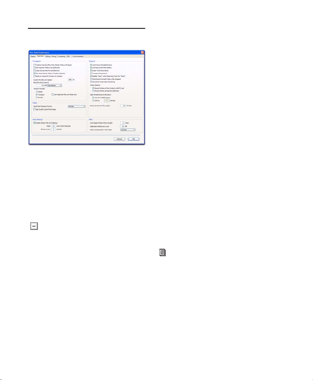
Operation Preferences
Transport Section
Timeline Insertion/Play Start Marker Follows
Playback When selected, the Timeline Insertion
and the Play Start Marker both move to the
point in the Timeline where playback stops.
When deselected, the Timeline Insertion and
Play Start Marker do not follow playback, but return to the point in time where playback began.
Press Start+N (Windows) or Control+N
(Mac) to toggle the Timeline Insertion/Play
Start Marker Follows Playback preference
on and off.
Edit Insertion Follows Scrub/Shuttle When selected, the edit cursor automatically locates to
the point where scrubbing stops.
Audio During Fast Forward/Rewind When selected, audio is audible during fast forward or rewind.
Play Start Marker Follows Timeline
Selection When enabled, the Play Start Marker
snaps to the Timeline Selection Start Marker
when you move the Timeline Selection, draw a
new Timeline Selection, or adjust the Timeline
Selection Start. When disabled, the Play Start
Marker doesn’t move with the Timeline selection.
Reserve Voices for Preview in Context (Pro Tools
HD Only) When enabled, Pro Tools reserve the
appropriate number of voices for preview in
context (previewing audio files in DigiBase during session playback). The number of available
voices is reduced by the channel width of the selected Audition Paths on the Output page of the
I/O Setup window. For example, if the number
of playback voices is set to 48 in the Playback
Engine, and you have a stereo audition path selected in the I/O Setup, only 46 voices will be
available for tracks. If you have a 5.1 audition
path, only 42 voices will be available. When this
option is disabled, you will not be able to preview in context if there are not enough available
voices.
Custom Shuttle Lock Speed Sets the highest fastforward Shuttle Lock speed (key 9) for Shuttle
Lock modes (Classic or Transport). The range for
this setting is 50–800%.
For more information, see “Custom Shuttle
Lock Speed” on page 443.
Back/Forward Amount Sets the default length of
Back, Back and Play, Forward and Forward and
Play. The timebase of the Back/Forward Amount
settings follows the Main Time Scale by default,
or you can deselect Follow Main Time Scale and
select another timebase format: Bars:Beats,
Min:Sec, Time Code, Feet+Frames, or Samples.
Pro Tools Reference Guide76
Page 93

Numeric Keypad Mode
Numeric Keypad mode determines how the numeric keypad functions. You can always use the
numeric keypad to select and enter values in the
Event Edit Area, Edit Selection indicators, Main
and Sub Counters, and Transport fields.
Classic Selects a Shuttle Lock mode that emulates the way Pro Tools worked in versions lower
than 5.0. With the Numeric Keypad mode set to
Classic, you can play up to two tracks of audio in
Shuttle Lock mode. Press the Start key (Windows) or Control (Mac), followed by 0–9 for different play speeds. Press Plus (+) or Minus (–) to
reverse direction. Recall Memory Locations by
typing the Memory Location number, followed
by Period (.).
To customize the highest fast-forward Shuttle Lock speed, see “Custom Shuttle Lock
Speed” on page 443.
playback speeds are available in both forward
and reverse. You can also recall Memory Locations by typing Period (.), the Memory Location
number, and Period (.) again.
Use Separate Play and Stop Keys
When enabled, this option lets you start playback with the Enter key and stop playback with
the 0 key on the numeric keypad. This is useful
for quickly starting and stopping playback when
auditioning loop transitions. Use Separate Play
and Stop Keys is only available in Transport Numeric Keypad mode.
When this option is enabled, it overrides using the Enter key to add Memory Location
markers. Instead, press Period (.) and then
Enter on the numeric keypad to add a Memory Location marker.
Video Section
Transport Selects a Shuttle Lock mode that lets
you set a number of record and play functions,
and also operate the Transport from the numeric keypad. With the Numeric Keypad mode
set to Transport, you can play up to two tracks of
audio in Shuttle Lock mode. Press the Start key
(Windows) or Control (Mac), followed by 0–9
for different play speeds. Press Plus (+) or Minus
(–) to reverse direction. Recall Memory Locations by typing Period (.), the Memory Location
number, and Period (.) again.
To customize the highest fast-forward Shuttle Lock speed, see “Custom Shuttle Lock
Speed” on page 443.
Shuttle (Pro Tools HD Only) Selects a type of
shuttling different from that of Shuttle Lock
mode. With the Numeric Keypad mode set to
Shuttle, playback is triggered by pressing and
holding the keys on the numeric keypad—playback stops once the keys are released. Various
QuickTime Playback Priority Options
Normal This is the default setting for QuickTime
Movie Playback Priority. It gives no extra priority to movie playback over other screen update
tasks such as metering, moving faders, and so
on. In most cases you should use this setting.
Medium This setting gives QuickTime movie
playback a higher priority relative to other
Pro Tools screen update tasks. Use this setting if
you experience inconsistent QuickTime movie
playback with the Normal setting.
Highest This setting gives QuickTime movie
playback highest priority. In this mode,
Pro Tools disables screen activity and requires
you to use the Spacebar to stop playback. Use
this setting if you require uninterrupted QuickTime movie playback.
Chapter 7: Preferences 77
Page 94

High Quality QuickTime Image
Auto Backup Section
When enabled, Pro Tools decompresses both
fields of each interlaced frame of QuickTime
video. When viewing a QuickTime movie in the
Pro Tools Video window, select this option to
display the movie at the highest possible resolution. Deselecting this option can help improve
performance if your system experiences problems playing back a session with QuickTime
video.
Avid Video Errors Stop Playback
(Pro Tools HD with Avid Video Engine Only)
When selected, Pro Tools automatically stops
playback of audio and video if a single frame of
video is dropped.
When not selected, Pro Tools continues playback of audio even if frames are dropped. In
most cases, video playback will recover within a
few frames and continue playing audio and
video in sync.
Avid Video NTSC Has Setup (NTSC-J)
(Pro Tools HD with Avid Video Engine Only)
Enable Session File Auto Backup When selected,
Pro Tools automatically saves backups of your
Pro Tools session file while you work. Backups
are saved to in the Session Files Backup folder in
your session folder.
Keep specifies the total number of incremental
backups that are kept.
Backup Every Specifies how often the session is
saved.
Record Section
Latch Record Enable Buttons When selected,
multiple audio tracks can be record-enabled.
When not selected, multiple audio tracks cannot be record-enabled. Record-enabling an audio track takes other audio tracks out of recordenabled mode.
Link Record and Play Faders When selected,
Pro Tools does not remember separate fader levels for tracks when they are record-enabled, allowing you to maintain the same monitoring
level for tracks during recording and playback.
This preference lets you adjust the level of NTSC
video black output between 7.5 IRE (standard)
or 0 IRE. When this option is selected, output
level is 0 IRE.
Pro Tools Reference Guide78
Audio Track RecordLock (Pro Tools HD
Only) This option configures Pro Tools tracks to
either emulate a digital dubber, or to maintain
legacy behavior for track record status.
• When selected, the record-enabled audio
tracks remain record-enabled when playback or recording stops.
• When not selected, record-enabled audio
tracks are taken out of record enable when
Pro Tools is stopped. This prevents tracks
from remaining armed from pass to pass,
emulating track record behavior of a digital
dubber.
Page 95

Transport RecordLock (Pro Tools HD Only) This
option lets the Transport Record (the Record
button in the Transport controls) be configured
to either emulate a digital dubber, or to maintain legacy behavior for the Transport master
Record.
• When selected, the Transport Record remains armed when playback or recording
stops. This saves having to re-arm the
Transport between takes, emulating digital
dubber behavior.
• When not selected, the Transport Record
disarms when Pro Tools is manually
stopped or stops due to a loss of time code.
This replicates standard Pro Tools recording behavior.
The Transport RecordLock preference is automatically disabled and grayed out when Destructive record mode is enabled.
Disable “Input” When Disarming Track (In “Stop”)
(Pro Tools HD Only) For flexibility, TrackInput
monitoring can be customized to remain selected regardless of track record status, or to automatically switch to Auto Input monitoring after a recording pass. This lets you optimize
monitoring for a typical dubbing workflow (in
which you might want tracks to remain in Input
Only mode until explicitly switched to Auto Input monitoring) or a typical music tracking
workflow (in which leaving a track in Input
Only monitoring mode after recording can result in accidental double-monitoring).
• When selected, taking an audio track out of
record enable (any mode) takes it out of Input Only mode, regardless of the global
monitor mode, and switches it to monitor
audio from disk only.
• When not selected, audio tracks remain in
Input Only monitoring mode until explicitly switched to Auto Input monitoring.
Mute Record-Armed Tracks While Stopped
(Pro Tools HD Only) This setting determines
monitor status of record-armed tracks.
• When selected, Pro Tools mutes all recordenabled tracks when the transport is
stopped. Input can still be monitored while
stopped using the TrackInput Monitor button.
• When not selected, Pro Tools does not
mute audio input on record-enabled tracks
when the transport is stopped.
PEC/Direct Style Input Monitoring (Pro Tools HD
Only) This option changes the way the Track-
Input monitoring mode is indicated on-screen
(and on supported control surfaces) to emulate
“PEC” (playback) and “Direct” (input/bus) indication on some large format consoles.
• When not selected, the TrackInput button
shows the letter “I.” The button remains
gray to indicate Auto Input mode and
lights green to indicate Input Only mode.
• When selected, the TrackInput button remains gray and shows the letter “D” to indicated Input Only mode (“Direct”); it
lights green and shows the letter “P” to indicate Auto Input mode (“Pec” or playback).
Online Options
Record Online at Time Code (or ADAT)
Lock When selected, online recording begins as
soon as Pro Tools receives and locks to incoming time code.
Record Online at Insertion/Selection When selected, online recording begins at the edit cursor
location. Recording continues until Pro Tools
stops receiving time code. If you make a selection, Pro Tools records online for the length of
the selection.
Chapter 7: Preferences 79
Page 96

Open Ended Record Allocation
This preference determines how much of your
available hard drive space is allocated for recording.
Use All Available Space When selected, the
drive’s entire available space is allocated. Generally, this is a good setting for recording longer
takes, as it provides the maximum amount of
drive space. Additionally, when recording multiple tracks, the files are spread across your drive.
This can sometimes slow down the recording
process for hard drives that use certain file systems, including HFS+ and NTFS.
Limit To Sets the maximum allowable recording
duration for one take. This can help reduce the
time it takes to begin recording by allocating
only a portion of your hard drive. The number
of minutes specified is allocated for each recordenabled track. You may want to experiment
with this number to achieve the recording performance you want.
If you do not regularly record longer takes, set a
smaller length (such as a low multiple of the
song’s total length).
DestructivePunch File Length (Pro Tools HD
Only)
Misc (Miscellaneous) Section
(Pro Tools HD Only)
Auto Region Fade In/Out Length Sets a default
length for fade-ins and fade-outs automatically
applied to region boundaries. Using automatic
fade-ins and fade-outs saves you the trouble of
editing to zero-crossings or creating numerous
rendered fades in order to eliminate clicks or
pops in playback. Autofades are not written to
disk. Value range is from 0–10 ms for the Auto
Region Fade In/Out Length. A value of zero
means that no auto-fading will occur. The Auto
Fade value is saved with the session, and is automatically applied to all free-standing region
boundaries until you change it.
Calibration Reference Level Sets a default calibration reference level in dB when Pro Tools is
in Calibration mode. For audio interfaces that
have trims (such as the 192 I/O), see the interface’s guide for calibration instructions.
Delay Compensation Time Mode This option lets
you choose whether information in the Delay
Manager is displayed in milliseconds or samples. This option is only available when Delay
Compensation is enabled (Options > Delay
Compensation).
This preference sets the duration of consolidated audio files when preparing tracks for
DestructivePunch mode. The default value for
this setting is 25 minutes.
Pro Tools Reference Guide80
Page 97

Editing Preferences
Regions Section
Region List Selection Follows Edit
Selection When selected, selecting a region in a
track also selects it in the Region List.
The following preferences determine which regions, or takes, appear in this list:
Includes Take Region Names That Match Track
Names When selected, only regions that share
the same root name with the track and playlist
appear in the Matches Right-click submenu or
the Alternates pop-up menu.
Includes Take Region Lengths That Match When
selected, only regions that match the length of
the current selection appear in the Matches
Right-click submenu or the Alternates pop-up
menu.
“Separate Region” Operates On All Related
Takes When selected, editing a region with the
Separate Region command also affects all other
related takes (recording passes) with the same
User Time Stamp. This option helps you compare different sections from a group of related
takes.
Edit Selection Follows Region List
Selection When selected, selecting a region in
the Region List causes Pro Tools to highlight
that region’s occurrence in a track.
Auto-Name Separated Regions When selected,
Pro Tools automatically names newly separated
regions by appending a number to the region’s
name.
“Matching Start Time” Takes List
When you Right-click, Control-click (Windows), or Command-click (Mac) a region in a
track, Pro Tools displays a list of regions (either
in the Matches Right-click submenu or the Alternates pop-up menu) whose time stamp
matches the current Cursor location.
Memory Locations Section
Auto-Name Memory Locations When
Playing When selected, Pro Tools gives new
Memory Locations default names based on their
time location in the session. The time units currently chosen in the View menu determine the
units for the names.
Recall Memory Location at Original Track When
selected, Memory Locations that recall a selection also recall the track in which the selection
was made.
Tracks Section
New Tracks Default To Tick Timebase When selected, all new tracks default to ticks. When deselected, audio, Auxiliary Input, Master Fader,
and VCA (Pro Tools HD only) tracks default to
samples.
Chapter 7: Preferences 81
Page 98

Fades Section
Crossfade Preview Pre-Roll This option specifies
the amount of pre-roll to be added when you are
auditioning crossfades in the Fades dialog.
Remove Range Selection After Zooming
In When selected, the current Edit selection col-
lapses into an insertion point after zoom toggling in. Zoom toggling back out reverts to the
previous selection.
Crossfade Preview Post-Roll This option specifies the amount of post-roll to be added when
you are auditioning crossfades in the Fades dialog.
QuickPunch/TrackPunch Crossfade Length Specifies a default length for crossfades created by
QuickPunch or TrackPunch (Pro Tools HD only)
recordings. Crossfades occur before the punch
in and after the punch out.
Preserve Fades when Editing This option preserves fade-ins and fade outs, and converts separated crossfades into corresponding fade-ins
and fade-outs.
Default Fade Settings
Fade In Selects the default envelope shape for
fade-ins.
Fade Out Selects the default envelope shape for
fade-outs.
Crossfade Selects the default envelope shape for
crossfades.
REX Selects the default envelope shape for fades
and crossfades between regions (“slices”) in imported REX files.
Track Height Selects Last Used, Medium, Large,
Extreme, or Fit To Window for the Zoom Toggle
Track Height.
Track View Selects Waveform/Notes,
Warp/Notes, Last Used, or No Change for the
Zoom Toggle Track View.
Separate Grid Settings When Zoomed In When
selected, this option retains the same (current)
grid setting when zoom toggling in or out.
When this option is deselected, the grid setting
stored with Zoom toggle is recalled when zoom
toggling in.
Zoom Toggle Follows Edit Selection When selected, zoom toggle automatically follows the
current Edit selection. When disabled, changing
the Edit selection has no affect on the currently
toggled-in track.
Levels of Undo
This preference sets the maximum number of
actions that can be undone with the multiple
undo feature. Setting this to a lower number can
speed up the performance of slower computers.
Pro Tools supports up to 32 Levels of Undo.
Zoom Toggle Section
Vertical Zoom Selects either Selection or Last
Used for the Zoom Toggle Vertical Zoom.
Horizontal Zoom Selects either Selection or Last
Used for the Zoom Toggle Horizontal Zoom.
Pro Tools Reference Guide82
Page 99

Mixing Preferences
Setup Section
Sends Default to –INF When selected, the initial
fader level of newly-created sends is set to –∞
(no audible signal level). When not selected, the
initial fader level of newly-created sends is set to
0 dB.
Use Absolute Pan Linking (Pro Tools HD
Only) This option affects behavior of grouped
pan controls.
• When selected, grouped pan controls do
not maintain relative offsets when any of
the grouped pan controls is adjusted. All
grouped pan controls snap to the absolute
value of the adjusted control.
• When not selected, grouped pan controls
maintain relative offsets when any of the
linked controls is adjusted.
Default EQ
This preference lets you choose any installed EQ
plug-in as the default, which makes it available
for quick assignment, both on-screen and on
ICON worksurfaces (Pro Tools HD only). Onscreen, the plug-in appears at the top of the Insert selector pop-up menu. On ICON worksurfaces, the plug-in appears first in the list of
menu choices on the rotary encoders.
Default Dynamics
Send Pans Default to Follow Main Pan When se-
lected, newly created sends have Follow Main
Pan turned on, so the Send Pan controls follow
the pan controls of the track. When not selected, newly created sends have Follow Main
Pan turned off.
Link Mix and Edit Group Enables When selected,
this option links enabling and disabling of Mix
and Edit Groups. For example, enabling Group
A in the Mix Window automatically enables
Group A in the Edit window.
This preference lets you choose any installed
Dynamics plug-in as the default, which makes it
available for quick assignment, both on-screen
and on ICON worksurfaces (Pro Tools HD only).
On-screen, the plug-in appears at the top of the
Insert selector pop-up menu. On ICON worksurfaces, the plug-in appears first in the list of
menu choices on the rotary encoders.
Chapter 7: Preferences 83
Page 100

Controllers
Automation Section
Edit Window Follows Bank Selection If you are
using a supported control surface with
Pro Tools, this option scrolls the Edit window to
display the selected bank of tracks when you
switch banks on the control surface, ensuring
that the current bank is viewable on-screen.
Mix Window Follows Bank Selection If you are
using a supported control surface with
Pro Tools, this option scrolls the Mix window to
display the selected bank of tracks when you
switch banks on the control surface, ensuring
that the current bank is viewable on-screen.
“Scroll to Track” Banks Controllers When using
a control surface (such as D-Control or ProControl) you can select this option to bank control surface faders to a numbered track when using the Track > Scroll to Track command.
Always Fill Channel Strips When Banking If you
are using an ICON worksurface (Pro Tools HD
only), or other supported Digidesign control
surface, you can select this option to maximize
the number of channels displayed when banking. This setting optimizes the Bank commands
to prevent the display of a small number of
channels at the extremes of the surface.
Touch Timeout If you are writing automation in
Touch mode and you stop moving a non-touch
sensitive fader or encoder, Pro Tools continues
to write automation for the Touch Timeout
value.
After the Touch Timeout period, writing of automation stops and the automation data returns
to its previous automation value at the rate specified in the AutoMatch Time setting.
Smooth and Thin Data After Pass When selected, Pro Tools automatically smooths and
then applies the specified amount of thinning
to the automation data created in an automation pass.
Degree of Thinning Specifies the amount of thinning performed on automation data when you
using the Thin Automation command, or if you
have selected the Smooth and Thin Data After
Pass option.
Plug-in Controls Default to Auto-Enabled When
selected, all applicable controls of newly added
plug-ins are enabled for automation. When not
selected, the controls of newly added plug-ins
must be manually enabled for automation.
Suppress Automation “Write To” Warnings
(Pro Tools HD Only) When selected, Pro Tools
suppresses the warnings that appear after invoking any of the Write Automation To Start, Selection, End, or Punch commands and then stopping the transport.
Latching Behavior for Switch Controls in
“Touch” This option determines the behavior of
switch-type controls (such as mute or plug-in
bypass) when writing automation in Touch
mode.
• When selected, controls in Touch mode
will latch in their current state. If an existing breakpoint is encountered, writing of
automation stops. If the transport is
stopped while writing, the control will
AutoMatch to the underlying value.
• When not selected, controls in Touch
mode will not latch.
Pro Tools Reference Guide84
 Loading...