

Page 1

Getting Started
with MIX
Version 5.1.3 on Macintosh
Version 5.3.1 on Windows
Digidesign
2001 Junipero Serra Boulevard
Daly City, CA 94014-3886 USA
tel: 650·731·6300
fax: 650·731·6399
Technical Support (USA)
tel: 650·731·6100
fax: 650·731·6384
Product Information (USA)
tel: 650·731·6102
tel: 800·333·2137
International Offices
Visit the Digidesign Web site
for contact information
Web Site
www.digidesign.com
Page 2

Copyright
This guide is copyrighted ©2002 by Digidesign, a division of
Avid Technology, Inc. (hereafter “Digidesign”), with all rights
reserved. Under copyright laws, this guide may not be
duplicated in whole or in part without the written consent of
Digidesign.
DIGIDESIGN, AVID and PRO TOOLS are trademarks or
registered trademarks of Digidesign and/or Avid Technology,
Inc. All other trademarks are the property of their respective
owners.
All features and specifications subject to change without
notice.
PN 932710142-00 REV A 06/02
Page 3

contents
Chapter 1. Introduction
Pro Tools TDM Systems
System Requirements
Digidesign Registration
About the Pro Tools Guides
. . . . . . . . . . . . . . . . . . . . . . . . . . . . . . . . . . . . . . . . . . . . . . . . . . . . . . 1
. . . . . . . . . . . . . . . . . . . . . . . . . . . . . . . . . . . . . . . . . . . . . . . . . . . . 1
. . . . . . . . . . . . . . . . . . . . . . . . . . . . . . . . . . . . . . . . . . . . . . . . . . . . . 3
. . . . . . . . . . . . . . . . . . . . . . . . . . . . . . . . . . . . . . . . . . . . . . . . . . . . 5
. . . . . . . . . . . . . . . . . . . . . . . . . . . . . . . . . . . . . . . . . . . . . . . . . 6
Chapter 2. Macintosh Configuration
Installing Pro Tools Hardware
Installing Pro Tools Software
Checking Your TDM System and Launching Pro Tools
Configuring Pro Tools
. . . . . . . . . . . . . . . . . . . . . . . . . . . . . . . . . . . . . . . . . . . . . . . . . . . . . 17
. . . . . . . . . . . . . . . . . . . . . . . . . . . . . . . . . . . . . . . . . . . . . . . . 7
. . . . . . . . . . . . . . . . . . . . . . . . . . . . . . . . . . . . . . . . . . . . . . . 11
Chapter 3. Windows Configuration
Installing Pro Tools
Upgrading to Windows 2000 with IBM IntelliStation E Pro Model 6846
Configuring Your Computer
Installing Pro Tools Hardware
Installing Pro Tools Software
Checking Your TDM System and Launching Pro Tools
Launching Pro Tools the First Time
Configuring Pro Tools
. . . . . . . . . . . . . . . . . . . . . . . . . . . . . . . . . . . . . . . . . . . . . . . . . . . . . . 21
. . . . . . . . . . . . . . . . . . . . . . . . . . . . . . . . . . . . . . . . . . . . . . . . 22
. . . . . . . . . . . . . . . . . . . . . . . . . . . . . . . . . . . . . . . . . . . . . . . 25
. . . . . . . . . . . . . . . . . . . . . . . . . . . . . . . . . . . . . . . . . . . . . . . 29
. . . . . . . . . . . . . . . . . . . . . . . . . . . . . . . . . . . . . . . . . . . . . . . . . . . . . 34
. . . . . . . . . . . . . . . . . . . . . . . . . . . . . . . . . . . . . . . . . . . 7
. . . . . . . . . . . . . . . . . . . . . . . . . . . . . . 15
. . . . . . . . . . . . . . . . . . . . . . . . . . . . . . . . . . . . . . . . . . . 21
. . . . . . . . . . . . . . . . . 21
. . . . . . . . . . . . . . . . . . . . . . . . . . . . . . 31
. . . . . . . . . . . . . . . . . . . . . . . . . . . . . . . . . . . . . . . . . . . 33
Contents
iii
Page 4

Chapter 4. Connecting Your Studio
Setting Up Your Studio
Example Studio Setup with a Mixing Console
Example Studio Setup without a Mixing Console
Connecting Equipment with Digital Audio Ins and Outs
Connecting Effects Units
Connecting MIDI Devices
Connecting SMPTE Synchronization Devices
. . . . . . . . . . . . . . . . . . . . . . . . . . . . . . . . . . . . . . . . . . . . . . . . . . . 39
. . . . . . . . . . . . . . . . . . . . . . . . . . . . . . . . . . . . . . . . . . . . . . . . . . 42
. . . . . . . . . . . . . . . . . . . . . . . . . . . . . . . . . . . . . . . . . . . . . . . . . . 43
. . . . . . . . . . . . . . . . . . . . . . . . . . . . . . . . . . . . . . . . . . 39
. . . . . . . . . . . . . . . . . . . . . . . . . . . . . . . . . . . 40
. . . . . . . . . . . . . . . . . . . . . . . . . . . . . . . . . 41
. . . . . . . . . . . . . . . . . . . . . . . . . . . . 42
. . . . . . . . . . . . . . . . . . . . . . . . . . . . . . . . . . . . 44
Chapter 5. Working with Pro Tools
Session Basics
Transport Controls
Navigating
Tracks
. . . . . . . . . . . . . . . . . . . . . . . . . . . . . . . . . . . . . . . . . . . . . . . . . . . . . . . . . . . . . . . 52
Regions Lists
Importing Audio
Basic Recording
Editing
. . . . . . . . . . . . . . . . . . . . . . . . . . . . . . . . . . . . . . . . . . . . . . . . . . . . . . . . . . . . . . . 60
Mixing
. . . . . . . . . . . . . . . . . . . . . . . . . . . . . . . . . . . . . . . . . . . . . . . . . . . . . . . . . . . . . . . 63
. . . . . . . . . . . . . . . . . . . . . . . . . . . . . . . . . . . . . . . . . . . . . . . . . . . . . . . . . 47
. . . . . . . . . . . . . . . . . . . . . . . . . . . . . . . . . . . . . . . . . . . . . . . . . . . . . . 51
. . . . . . . . . . . . . . . . . . . . . . . . . . . . . . . . . . . . . . . . . . . . . . . . . . . . . . . . . . . . 52
. . . . . . . . . . . . . . . . . . . . . . . . . . . . . . . . . . . . . . . . . . . . . . . . . . . . . . . . . . 56
. . . . . . . . . . . . . . . . . . . . . . . . . . . . . . . . . . . . . . . . . . . . . . . . . . . . . . . . 56
. . . . . . . . . . . . . . . . . . . . . . . . . . . . . . . . . . . . . . . . . . . . . . . . . . . . . . . . 57
. . . . . . . . . . . . . . . . . . . . . . . . . . . . . . . . . . . . . . . . . . . 47
Appendix A. Connecting SCSI Drives
SCSI Requirements
Connecting SCSI Drives
Quick Formatting a SCSI Drives
General Hard Drive Maintenance Information
Using Macintosh Drives on Windows Systems
Appendix B. DigiTest Error Codes
. . . . . . . . . . . . . . . . . . . . . . . . . . . . . . . . . . . . . . . . . . . . . . . . . . . . . . 69
. . . . . . . . . . . . . . . . . . . . . . . . . . . . . . . . . . . . . . . . . . . . . . . . . . . 71
. . . . . . . . . . . . . . . . . . . . . . . . . . . . . . . . . . . . . . . . . . . . . 71
. . . . . . . . . . . . . . . . . . . . . . . . . . . . . . . . . . . . . . . . . . . . 77
. . . . . . . . . . . . . . . . . . . . . . . . . . . . . . . . . . . . . . . . . 69
. . . . . . . . . . . . . . . . . . . . . . . . . . . . . . . . . . . 73
. . . . . . . . . . . . . . . . . . . . . . . . . . . . . . . . . . . 75
Appendix C. Configuring OMS (Macintosh Only)
Appendix D. Digidesign Control Panel (Macintosh Only)
Getting Started with MIX
iv
. . . . . . . . . . . . . . . . . . . . . . . . . . . . . . . 79
. . . . . . . . . . . . . . . . . . . . . . . 83
Page 5

Appendix E. Digidesign WaveDriver (Windows Only)
Introduction
Installing the WaveDriver
How to Change WaveDriver Settings
Installing DigiGain
Removing DigiGain
How to Use DigiGain
. . . . . . . . . . . . . . . . . . . . . . . . . . . . . . . . . . . . . . . . . . . . . . . . . . . . . . . . . . . 85
. . . . . . . . . . . . . . . . . . . . . . . . . . . . . . . . . . . . . . . . . . . . . . . . . . 85
. . . . . . . . . . . . . . . . . . . . . . . . . . . . . . . . . . . . . . . . . . 87
. . . . . . . . . . . . . . . . . . . . . . . . . . . . . . . . . . . . . . . . . . . . . . . . . . . . . . . 90
. . . . . . . . . . . . . . . . . . . . . . . . . . . . . . . . . . . . . . . . . . . . . . . . . . . . . . 90
. . . . . . . . . . . . . . . . . . . . . . . . . . . . . . . . . . . . . . . . . . . . . . . . . . . . . 91
. . . . . . . . . . . . . . . . . . . . . . . . . . . . 85
Index
. . . . . . . . . . . . . . . . . . . . . . . . . . . . . . . . . . . . . . . . . . . . . . . . . . . . . . . . . . . . . . . . . . . . . 93
Contents
v
Page 6

Getting Started with MIX
vi
Page 7

chapter 1
Introduction
Welcome to Pro Tools|24 MIX!
Pro Tools|24 MIX and Pro Tools|24 audio cards
and interfaces, together with Pro Tools software
version 5.1.3 for Macintosh or 5.3.1 for Windows, provide 24-bit hard disk recording, editing, processing, mixing, and I/O capabilities to
Pro Tools. This guide tells you how to install
Pro Tools|24 MIX and Pro Tools|24 hardware
and Pro Tools version 5.1.3 software on Macintosh and Pro Tools version 5.3.1 software on
Windows platforms. System and installation
tests are provided, as well as a chapter covering
the basics of working with Pro Tools (designed
for anyone who is new to Pro Tools).
Pro Tools TDM Systems
Pro Tools 5.1.3 for Macintosh and Pro Tools
5.3.1 for Windows support the following systems:
Pro Tools|24 MIX
A core system includes:
• MIX Core card
• Pro Tools software
• Digidesign audio interface
(sold separately)
MIXplus
A MIXplus system includes:
• MIX Core card
• MIX Farm card
• Pro Tools software
• Digidesign audio interface
(sold separately)
3
MIX
A MIX3 system includes
• MIX Core card
• Two MIX Farm cards
• Pro Tools software
• Digidesign audio interface
(sold separately)
All Pro Tools|24 MIX systems provide:
• Up to 64 tracks of recording and playback of
24-bit and 16-bit audio files
• TDM digital mixing and DSP plug-in environment
• Non-linear, random-access editing and mix
automation
• MIDI recording, playback and editing
Chapter 1: Introduction
1
Page 8

Pro Tools|24
A core system includes:
• d24 Audio card
• DSP Farm card
• Pro Tools software
• Digidesign audio interface
(sold separately)
A core Pro Tools|24 system provides:
• Up to 32 tracks of recording and playback of
24-bit and 16-bit audio files
• TDM digital mixing and DSP plug-in environment
• Non-linear, random-access editing and mix
automation
• MIDI recording, playback and editing
Audio Interfaces
1622 I/O
◆
Analog: 1/4" TRS (balanced or unbalanced)
connectors. Inputs are variable from +4 dBu to
–10 dBV; outputs are selectable between +4 dBu
or –10 dBV
◆
Digital: RCA (S/PDIF) connectors
Digidesign 24-Bit ADAT Bridge I/O and the Original ADAT Bridge I/O
◆
Analog: 1/4" TRS (balanced) connectors, +4
dBu or –10 dBV
Digital: XLR (AES/EBU) or RCA (S/PDIF) con-
◆
nectors
Optical: Two pairs of EIAJ fiber optic connec-
◆
tors
MIX systems do not support HD-series audio interfaces (such as the 96 I/O and the
192 I/O.
To record and play audio you must have one of
the following Digidesign audio interfaces:
888|24 I/O
Analog: XLR (balanced or unbalanced) con-
◆
nectors, +4 dBu or –10 dBV
◆
Digital: XLR (AES/EBU) or RCA (S/PDIF) con-
nectors
882|20 I/O
◆
Analog: 1/4" TRS (balanced or unbalanced)
connectors, +4 dBu or –10 dBV
◆
Digital: RCA (S/PDIF) connectors
Getting Started with MIX
2
Pro Tools|24 MIX and Pro Tools|24 systems also support some older Digidesign audio interfaces, such as the 888 I/O and
882 I/O.
Page 9

System Requirements
The CPU, hard disk, monitoring, and MIDI requirements for Pro Tools differ depending on
your system configuration and computer platform (Macintosh or Windows). The requirements for each configuration are listed below.
Compatibility Information
• Three unused adjacent PCI slots for
Pro Tools|24 MIX
• For higher track counts, 1 unused PCI card
slot for a Digidesign-approved SCSI HBA.
• For expanded systems, the expansion chassis card takes the place of the Pro Tools card
in the PCI slot and the Pro Tools card is
placed in the chassis
• Apple System software version 9.1 or later
3
systems
Digidesign can only assure compatibility and
provide support for hardware and software it
has tested and approved. For a list of Digidesignqualified computers, operating systems, and
third-party devices, refer to the latest compatibility information on the Digidesign Web site:
www.digidesign.com
Computer Requirements
Macintosh
• A Digidesign-qualified Power Macintosh computer with:
• Minimum 256 MB RAM (Pro Tools application “Preferred” memory allocation set to
70 MB and DAE “Preferred” memory allocation set to 60 MB); virtual memory is not
supported
• Additional RAM is highly recommended if
you plan to use other applications concurrently with Pro Tools
• One unused PCI slot for Pro Tools|24 MIX
systems
• Two unused adjacent PCI slots for
Pro Tools|24 MIXplus systems and
Pro Tools|24 systems
Mac OS X is not supported.
• System Utility software (included with
Pro Tools):
• OMS (Open Music System) software version 2.3.8 or later
• Apple QuickTime System Extension version 4.1.2 or later
• ATTO ExpressPro-Tools version 2.3.2 or
later
• Color monitor required, minimum resolution
of 1024 x 768
• A Digidesign-qualified floppy drive, along
with the appropriate driver software (included
on the Pro Tools Installer CD-ROM) is required to authorize some plug-ins
The maximum number of Pro Tools|24 and
Pro Tools|24 MIX cards supported in an expansion chassis is seven. However, there
may be further restrictions depending on
your operating system and the specific
model of your expansion chassis. For more
information, visit the Digidesign Web site
at:
www.digidesign.com
Chapter 1: Introduction
3
Page 10

Windows
• A Digidesign-qualified, single processor
Pentium III, or Pentium 4-based (highly recommended) computer:
• Minimum 256 MB RAM (required for 64voice performance)
• Additional RAM is highly recommended if
you plan to use other audio or MIDI applications concurrently with Pro Tools
• One unused PCI slot for Pro Tools|24 MIX
systems
• Two unused adjacent PCI slots for
Pro Tools|24 MIXplus systems and
Pro Tools|24 systems
• Three unused adjacent PCI slots for
Pro Tools|24 MIX
• For higher track counts, 1 unused PCI card
slot for a Digidesign-approved SCSI HBA.
• For expanded systems, the expansion chassis card takes the place of the Pro Tools card
in the PCI slot and the Pro Tools card is
placed in the chassis
• VIA Apollo Pro133 chipset (for Pentium III)
or
Intel 860 or 850 chipset (for Pentium 4)
• Award BIOS
• A CD-ROM drive
• An AGP display card is strongly recommended
• Windows 2000 Professional Edition with
Service Pack 2 or higher
• QuickTime 5 for Windows 2000
• Color monitor required, minimum resolution
of 1024 x 768
• Additional RAM is highly recommended if
you plan to use other applications concurrently with Pro Tools
3
systems
Hard Drive Requirements
Macintosh
For audio recording and storage, all Pro Tools
TDM systems require one or more Digidesignqualified FireWire drives or SCSI drives attached
to a qualified PCI SCSI HBA card.
To provide full 64-track, 24-bit, 48 kHz performance, a TDM system must include at least two
Digidesign-qualified FireWire hard drives or
SCSI hard drives attached to a qualified SCSI
HBA (host bus adapter) card.
For 64-track sessions that have substantial edit
densities (such as one edit every third of a second across 64 voices) or large amounts of crossfades, up to four FireWire or SCSI drives may be
required, allocated with 16 tracks per drive and
two drives per SCSI channel.
Dedicated internal IDE/ATA drives can provide
32-track performance to all TDM systems.
Refer to the Digidesign Web site for compatible
hard drives and SCSI HBA cards:
www.digidesign.com
Older Power Macintosh Computers
Power Macintosh 9500 and 9600 computers
have two SCSI busses: an internal fast SCSI bus
and an external narrow SCSI bus. On these machines, sessions with higher track counts and
high edit density require a SCSI HBA card. For
optimum performance without a SCSI HBA
card, use the internal fast SCSI bus.
For higher track counts on Power Macintosh
9500, 9600, and Beige G3 computers,
avoid using the external narrow SCSI drive.
Getting Started with MIX
4
Page 11

Windows
MIDI Requirements
For optimal audio recording and storage with
your Pro Tools TDM system, use one or more
Digidesign-qualified FireWire drives or SCSI
drives attached to a qualified PCI SCSI HBA card
or qualified built-in SCSI HBA connector on the
motherboard. Drives should be initialized with
Windows Disk Manager as NTFS or FAT32.
For optimal disk priming, set the cluster size
to 32k using Windows Disk Manager or
Partition Magic.
To provide full 64-track, 24-bit, 48 kHz performance, a TDM system must include at least two
Digidesign-qualified FireWire or SCSI hard
drives attached to a qualified SCSI HBA (host
bus adapter) card.
For 64-track sessions that have substantial edit
densities (such as one edit every third of a second across 64 voices) or large amounts of crossfades, up to four FireWire or SCSI drives may be
required, allocated with 16 tracks per drive and
two drives per SCSI channel.
For best 64-track, 24-bit performance, use 4
hard drives, with audio files distributed
among them.
Both USB and serial MIDI interfaces work effectively with Pro Tools.
PCI-based serial expanders do not work with serial MIDI interfaces on Macintosh systems. Serial MIDI interfaces require a qualified modemto-serial port adapter. Refer to the Digidesign
compatibility page for supported adapters:
www.digidesign.com
Digidesign Registration
Make sure to complete and return the registration card included with your Pro Tools TDM system. Registered users are entitled to one year of
free technical support, and will receive periodic
software updates and upgrade notices.
Pro Tools TDM systems can record and playback
up to 32 tracks using ATA 100 (or higher) drives.
Pro Tools TDM cannot record to or playback
from the system drive.
Refer to the Digidesign Web site for compatible
hard drives and SCSI HBA cards:
www.digidesign.com
Chapter 1: Introduction
5
Page 12

About the Pro Tools Guides
The following symbols are used to highlight important information:
PDF versions of many Pro Tools guides are installed automatically with Pro Tools, several of
which can be easily accessed from the Help
menu in Pro Tools. Additional documentation,
including important ReadMe files, can be found
in Digidesign/Pro Tools/Release Notes & Documentation. To read the guide online, or print it,
you must install
Pro Tools Installer CD).
Acrobat Reader
(included on the
Conventions Used in This Guide
Digidesign guides use the following conventions to indicate menu choices and key commands:
Convention Action
File > Save
Session
Control+N While pressing the Control key,
Option-click While pressing the Option key,
Choose Save Session from the
File menu
press the N key
click the mouse button
User Tips are helpful hints for getting the
most from your system.
Important Notices include information that
could affect your data or the performance of
your system.
Shortcuts show you useful keyboard or
mouse shortcuts.
Cross References point to related sections in
other Digidesign guides.
Right-click
(Windows)
Getting Started with MIX
6
Click with the right mouse button
Page 13

chapter 2
Macintosh Configuration
To configure your Pro Tools|24 MIX or
Pro Tools|24 system for Macintosh, you will
need to install Pro Tools hardware and software,
verify your TDM system, then launch Pro Tools.
Installing Pro Tools Hardware
Pro Tools TDM Cards
The number of Pro Tools TDM cards will differ
depending on your system configuration. Card
components for each configuration are listed
below.
If you are using an Expansion Chassis to
add additional cards to your system, refer to
the
Expanded Systems Guide included with
your Pro Tools system.
Pro Tools|24 and Pro Tools|24 MIX
Hardware
Pro Tools|24 and Pro Tools|24 MIX hardware
comes in the following configurations:
Pro Tools|24 MIX
card and a 5-node TDM ribbon cable for connecting to other optional TDM-equipped cards.
Pro Tools|24 MIXplus
a MIX Farm card, and a 5-node TDM ribbon cable for connecting the MIX Core to the MIX
Farm and other optional TDM-equipped cards.
Includes a single MIX Core
Includes a MIX Core card,
Pro Tools|24 MIX3
two MIX Farm cards, and a 5-node TDM ribbon
cable for connecting the MIX Core to the MIX
Farm and other optional TDM-equipped cards.
Pro Tools|24
Farm card, and a 5-node TDM ribbon cable for
connecting them.
Includes a MIX Core card,
Includes a d24 audio card, a DSP
The MIX Core Card
The MIX Core card provides 24-bit, 64-track, 16channel I/O, direct-to-disk recording and playback to your Pro Tools 24 MIX system, as well as
DSP power for its mixing and processing capabilities.
audio interface
port
DigiSerial port
MIX Core card
This card includes a connector for attaching a
single 888|24 I/O, 882|20 I/O, 1622 I/O, 24-Bit
ADAT Bridge I/O, or the original ADAT
Bridge I/O audio interface. If you purchase the
optional 16-channel peripheral cable adapter,
you can attach two 8-channel audio interfaces.
Chapter 2: Macintosh Configuration
7
Page 14

The Digi-Serial port is for connecting a Digidesign Universal Slave Driver (USD), or a 9-pin device for use with the Pro Tools MachineControl
option.
The MIX Farm Card
The MIX Farm card provides more DSP power
for mixing, processing, and DSP software such
as the DigiRack plug-ins included with
Pro Tools. It also provides a connector for attaching a single 888|24 I/O, 882|20 I/O, or
1622 I/O, 24-Bit ADAT Bridge I/O, or the original ADAT Bridge I/O audio interface. If you purchase the optional 16-channel peripheral cable
adapter, you can attach two 8-channel audio interfaces. The DigiSerial port is for connecting a
Digidesign Universal Slave Driver (USD), or a 9pin device for use with the Pro Tools MachineControl option.
audio interface
port
DigiSerial port
MIX Farm card
The d24 Audio Card
The d24 audio card provides 24-bit, 32-track, 16channel I/O, direct-to-disk recording and playback capabilities to your Pro Tools 24 system. It
also provides a connector for attaching a single
888/24 I/O, 882/20 I/O, or 1622 I/O Audio Interface. If you purchase the optional 16-channel
peripheral cable adapter, you can attach two 8-
channel audio interfaces. The DigiSerial port is
for connecting an optional Digidesign Universal
Slave Driver, or a 9-pin device for use with the
Pro Tools MachineControl option.
audio interface
port
DigiSerial port
d24 card
The DSP Farm
The DSP Farm provides the power for the
Pro Tools 24 system’s mixing and processing capabilities. It powers DSP software such as the DigiRack plug-ins included with Pro Tools. It also
provides a connector for attaching an 8-channel
audio interface.
audio interface
port
DSP Farm card
The 1622 I/O Audio Interface is not supported by the DSP Farm. It must be connected to a MIX Core, MIX Farm, or d24
card. Only one 1622 I/O can be connected
to any of these cards. The optional 16channel peripheral cable adapter is not supported by the 1622 I/O.
Getting Started with MIX
8
Page 15

The TDM Ribbon Cable
The TDM ribbon cable is used to connect multiple cards in your Pro Tools system so they can
share data along the TDM bus.
TDM Ribbon Cable
A 5-node cable comes with your system. If you
plan to use your system with an expansion chassis, you can order a TDM cable with more nodes
from your Digidesign dealer.
Installing the Pro Tools Cards
Install the Pro Tools cards:
1
Turn off your computer and any peripherals.
Leave your computer’s power cable plugged in
so the computer is grounded.
2
Open the computer case. The illustrations in
this section show a Blue & White Macintosh G3
and a Macintosh 9600 computer. Even if you are
using a different model, the installation should
be similar. For additional details on installing a
PCI card in your computer, refer to the computer’s documentation.
4
Install the MIX Core or d24 card (clock master
with primary audio interface) in the lowest
numbered slot in your computer.
Installing a Pro Tools card in a Macintosh G3
Before handling any card, discharge any
static electricity that may be on your clothes
or body by touching a grounded metal surface, such as the power supply case inside
your computer.
3
Remove the metal access port cover behind
the expansion slot you want to use by removing
the screw (if present) and sliding the cover out
from the access port.
Installing a Pro Tools card in a Macintosh 9600
5
Install the remaining Digidesign cards in suc-
cessive slots.
Pro Tools cards must be installed in a specific order that is dependent on the slot numbering of
the model of Macintosh you are using.
Chapter 2: Macintosh Configuration
9
Page 16

Group similar cards together (for example, put
all MIX Farm cards next to each other).
6
If installing a SCSI HBA card, install it in the
highest numbered remaining slot.
Check Digidesign’s Compatibility Documents for a list of Digidesign approved computers and supported SCSI driver versions:
www.digidesign.com
For 9500 and 9600 computers, the SCSI HBA
should reside before the video card.
Connect all TDM cards with the TDM ribbon cable:
1
Connect the first node of the cable to the first
TDM card. Make sure the TDM cable is facing
the right direction—align the white triangles on
the cable plug with the triangle on the card.
4
Secure the cards in place with the slot access
port screws you removed earlier and close your
computer.
Connecting Audio Interfaces
Pro Tools provides you with a choice of the
888|24 I/O, 882|20 I/O, 1622 I/O, 24-Bit ADAT
Bridge I/O, or the original ADAT Bridge I/O interfaces. These devices supply the inputs and
outputs for your system.
MIX systems do not support HD-series audio interfaces (such as the 96 I/O and the
192 I/O.
Pro Tools|24 MIX and Pro Tools|24 systems also support some older Digidesign audio interfaces: the 888 I/O and 882 I/O.
For instructions on connecting a 24-Bit
ADAT Bridge I/O, or the original ADAT
Bridge I/O, see the ADAT Bridge I/O Installation Guide.
Attaching the TDM ribbon cable to MIX Core and
MIX Farm cards
2
Push down gently but firmly until the node is
fully connected to the card. When the plug is
properly seated, the two tabs on the side of the
cable’s TDM connector will click shut. To detach
the ribbon cable, squeeze the tabs on the TDM
connector inward.
3
Attach the remaining nodes on the TDM cable
to subsequent cards.
It is OK to have ribbon connectors that go
unused. They should reside after the last
TDM card.
Getting Started with MIX
10
Connect the Pro Tools audio interfaces:
1 Connect the primary audio interface to the
primary MIX Core or d24 card with the provided interface cable. The primary audio interface functions as the clock master.
2 Connect additional audio interfaces to subse-
quent Digidesign audio cards.
If you are connecting both 888|24 and 882|20 or
1622 I/O Audio Interfaces to your system, for
best system performance, connect the 888|24 to
your MIX Core or d24 card, followed by any additional 888|24 interfaces to the next highestpriority cards (MIX Farm cards). Then connect
the 882|20 or 1622 I/O interfaces to subsequent
cards.
Page 17

You can use Digidesign’s 16-channel peripheral
cable adapter (optional) to connect two 8-channel audio interfaces to a single MIX Core, d24,
or MIX Farm card.
to Audio
Interface
cable
to Audio
Interface
cable
to Pro Tools card
Optional 16-channel peripheral cable adapter
3 If using multiple audio interfaces, connect the
Slave Clock Out of the primary interface to the
Slave Clock In of the second interface with the
provided BNC cable. Connect the Slave Clock
Out of the second interface to the Slave Clock In
of the next audio interface (and so forth).
78563412785634125/6
ANALOG OUTPUT ANALOG INPUT AES/EBU OUTPUT AES/EBU INPUT
78563412785634125/6
ANALOG OUTPUT ANALOG INPUT AES/EBU OUTPUT AES/EBU INPUT
1234567812345678
1234567812345678
7/8
7/8
ANALOG OUTPUTSANALOG INPUTS
ANALOG OUTPUTSANALOG INPUTS
OUT
OUT
1/2
3/4
1/2
3/4
IN
IN
SLAVE CLOCK
IN
SLAVE CLOCKINS/PDIF
COMPUTER
5/6
1/2
7/8
3/4
S/PDIFINS/PDIF
SLAVE CLOCKINSLAVE CLOCK
OUT
OUT
COMPUTER
5/6
1/2
7/8
3/4
S/PDIFINS/PDIF
SLAVE CLOCKINSLAVE CLOCK
OUT
OUT
IN
COMPUTER
OUT
S/PDIF
COMPUTER
OUT
Connecting multiple audio interfaces together
Installing Pro Tools Software
The complete Pro Tools software installation
process includes:
• Preparing your Apple System software for
Pro Tools
• Installing Pro Tools software
• Installing OMS
After software installation is completed, the first
time you launch Pro Tools you will be prompted
to enter your Pro Tools authorization code and
configure hardware. Instructions for this begin
in “Checking Your TDM System and Launching
Pro Tools” on page 15.
If you haven’t already installed Pro Tools
hardware, do so now. See “Installing
Pro Tools Hardware” on page 7 for instructions.
Apple System Software Settings
To ensure optimum performance with
Pro Tools, configure the Apple System software
with the following settings for OS 9.1 or later.
Mac OS X is not supported.
To configure the Apple System software for
optimum Pro Tools use:
1 In the Memory Control Panel do the follow-
ing:
• Set the Disk Cache to a Custom Setting of
512 K.
• Set Virtual Memory to Off.
• Set the Ram Disk to Off.
2 In the Energy Saver Control Panel, set the “in-
active” time to Never.
Chapter 2: Macintosh Configuration 11
Page 18

3 In the Appearance Control Panel do the fol-
lowing:
• Click the Fonts tab and set the Large System
Font to Chicago. In addition, deselect
“Smooth all fonts on screen.”
• Click the Sound tab and select None from the
Sound Track pop-up menu.
4 In the Extensions Manager Control Panel do
the following:
• Choose Mac OS 9.1 Base (or Mac OS 9.2 Base,
Mac OS 9.2.1, or Mac OS 9.2.2) from the Selected Set pop-up menu. This is done to avoid
any potential extensions conflicts.
• Click Restart to restart your computer.
To install Pro Tools software:
1 Locate the Pro Tools Installer CD for Macin-
tosh and place it in your CD-ROM drive. Locate
and double-click the file named “Install
Pro Tools.”
2 Select the hard drive on which to install
Pro Tools from the Install Location pop-up
menu. For maximum reliability, install
Pro Tools on your startup drive.
DigiTranslator Enables the exchange of audio
and video files, and sequences between
OMFI-compatible applications and Pro Tools.
For more information on DigiTranslator,
see the DigiTranslator Guide.
Procrastinator Add this item if you have a
Pro Tools|24 MIX system and one or more DSP
Farm cards and you want to use the Procrastina-
™
tor
extended delay plug-in. This is useful if you
plan to open old sessions that use the Procrastinator Plug-In. (Do not select this item if you
have a Pro Tools|24 system—Procrastinator is
automatically installed for you.)
Machine Control Users Guide Install this document if you also use Digidesign’s MachineControl option for Pro Tools.
5 After selecting from the above options, click
Install.
6 Select an initial set of Pro Tools Preferences.
These Preference “sets” have been pre-configured to include some of the more popular settings for post production, audio, and audio with
MIDI. After selecting a setting, click Continue.
3 Select the appropriate installer for your
Digidesign hardware: Pro Tools|24 MIX, or
Pro Tools|24.
4 Several optional items are listed directly below
the main installation choices. To install any of
these items, select them from the list:
Digidesign Control Panel Add this item if you
want to use your Digidesign hardware with
Sound Manager-compatible applications. For
more information, see Appendix D, “Digidesign
Control Panel (Macintosh Only).”
Getting Started with MIX12
Selecting a Pro Tools Preference
Preference settings can be customized at any
time in Pro Tools. See the Pro Tools Reference
Guide for more information about Preferences.
Page 19

7 For Pro Tools|24 MIX systems, you are
prompted to install the Surround Mixer plug-in.
This plug-in is required for mixing, mastering,
and monitoring in surround. Select Yes to install
Surround Mixer, or No for stereo, then click
Continue.
Installing Surround Mixer
8 If you installed Surround Mixer in the previ-
ous step, the Installer prompts you to select a
Surround Monitor Format. Select Standard
Pro Tools if your monitoring is configured for
Film Format, or select ProControl for DTS Format, then click Install.
Allocating Additional Memory to Pro Tools and DAE
Digidesign strongly recommends allocating additional RAM to both the Pro Tools and DAE applications.
To allocate additional memory to Pro Tools:
1 If Pro Tools is currently running, Quit
Pro Tools.
2 In the Finder, choose About This Computer
from the Apple menu.
3 If you have 3 megabytes or more of memory
available (as indicated in the Largest Unused
Block portion of this window), go to step 4. If
you have less than 3 megabytes of free memory
(3,000k), stop here: Do not allocate additional
memory to Pro Tools unless you install additional RAM in your computer.
4 Locate the Pro Tools application on your hard
drive, select it, and choose Get Info from the
Finder’s File menu.
5 Choose Memory from the Show pop-up
menu.
Selecting a Surround Monitor Format
9 When installation is complete, click Restart
(to restart your computer), then install OMS.
6 Enter the desired amount of memory above the
minimum requirement in the Preferred Size field.
For example, if the Preferred Size field currently
says “30410k” and you wish to allocate an additional 60 megabytes of memory (1 megabyte
equals 1024 kilobytes), enter “90410” into the
Preferred Size field.
7 Close the Get Info dialog.
The next time you start Pro Tools, it will use this
new memory allocation.
Chapter 2: Macintosh Configuration 13
Page 20

To allocate additional memory to DAE:
1 Start Pro Tools so that DAE can calculate its
basic memory allocation.
2 Go to the Finder and choose About This Com-
puter from the Apple menu.
3 If you have 3 megabytes or more of memory
available (as indicated in the Largest Unused
Block portion of this window), go to step 4. If
you have less than 3 megabytes of free memory
(3,000k), stop here: Do not allocate additional
memory to DAE unless you install additional
RAM in your computer.
4 Quit Pro Tools.
5 Open the DAE folder inside your System
Folder, select DAE, and choose Get Info from the
Finder’s File menu.
6 Choose Memory from the Show menu.
7 Enter the desired amount of memory above the
minimum requirement in the Preferred Size field.
For example, if the Preferred Size field currently
says “30410k” and you wish to allocate an additional 30 megabytes of memory (1 megabyte
equals 1024 kilobytes), enter “60410” into the
Preferred Size field.
Installing OMS
To use Pro Tools you must first install and configure the Open Music System (OMS). OMS,
which is included on the Pro Tools Installer CD,
has the following capabilities:
• Keeps track of which MIDI devices you are us-
ing, how they are connected, and which
patches they are using
• Enables MIDI hardware to communicate with
your music applications
• Provides timing services and inter-application
communication
OMS stores a description of your MIDI studio in
Studio Setup documents, which are edited in the
OMS Setup application. Once OMS is configured,
your music applications know which MIDI devices you are using by referencing the current
Studio Setup document.
To install OMS:
1 Insert the Pro Tools Installer CD in your CD-
ROM drive.
2 Open the OMS Installer folder and double-
click the Installer.
8 Close the Get Info dialog.
The next time you start Pro Tools, DAE will use
this new memory allocation.
Getting Started with MIX14
3 At the Install window, select the Easy Install
option, and set the Install Location to your Startup hard drive. Click Install.
4 Follow the on-screen installation instructions.
5 When the installation is complete, restart
your Macintosh.
If you are a first-time OMS user, see
Appendix C, “Configuring OMS (Macintosh Only)” for more information.
Page 21

Checking Your TDM System
and Launching Pro Tools
We strongly urge you to launch the DigiTest diagnostics application before your initial launch
to Pro Tools. Doing so ensures that you have all
cards recognized in the system, in the proper order, and with valid TDM ribbon cable connections.
DigiTest is located in the Digidesign Utilities
folder (see “Running DigiTest” on page 15).
When DigiTest has completed, restart your computer, then launch Pro Tools for the first time.
5 Turn on any MIDI interfaces and devices, or
synchronization peripherals.
6 Turn on your Pro Tools audio interfaces (such
as 888|24 I/O). On power up, the status LEDs
will flash. Wait at least fifteen seconds for the
audio interface to initialize, and the status LEDs
to stop blinking and stay lit.
If you launch Pro Tools without turning on your
audio interfaces, you will be prompted to turn
them on. Allow fifteen seconds for audio interfaces to power-up and the status LEDs to stop
blinking and stay lit, before clicking OK.
7 Turn on your computer.
You should also run DigiTest after making
any changes to your hardware setup (such
as adding or removing cards, adding or removing audio interfaces, adding or removing synchronization cables, and so on) to
verify that your system is correctly configured and functioning properly. After running DigiTest, restart your computer.
Starting Up Your System
Whenever you start your system, you must turn
on all of your system components in a specific
order.
Start your Pro Tools System in this order:
1 Make sure all your equipment (including your
CPU) is off.
2 For TDM systems with an expansion chassis,
turn on the expansion chassis.
3 Turn on external hard drives, if any. Wait ap-
proximately ten seconds for them to spin up to
speed.
Running DigiTest
Run the DigiTest diagnostics application to
identify TDM cards and verify that they are correctly installed and working.
DigiTest is included on the Pro Tools Installer
CD and installed with Pro Tools. DigiTest resides in the Digidesign Utilities folder located on
your hard drive, under Digidesign/Pro Tools/Pro
Tools Utilities.
Before you run DigiTest, lower the volume
of your monitoring system and all output
devices. Additionally, be sure to remove
your headphones. Very loud digital noise
may be emitted during the test.
To run DigiTest:
1 From the Digidesign Utilities folder, double-
click the DigiTest application program. DigiTest
opens and lists the supported cards it finds in
your system in their corresponding slot location.
4 Lower the volume of all output devices, then
turn on your Pro Tools audio interfaces.
Chapter 2: Macintosh Configuration 15
Page 22

If you have several TDM cards and connected
MIX-series I/Os, it may take awhile for the main
DigiTest screen to appear. This is due to the test
scanning for all cards and I/Os connected to the
system.
DigiTest window
If a supported card is installed and not listed,
check card seating and TDM FlexCable connection. Close DigiTest, power down your system,
and reinstall the cards (see “Installing the
Pro Tools Cards” on page 9). After power up, begin DigiTest again.
4 From the DigiTest window, click Run.
If you haven’t done so already, turn down
your speakers before running DigiTest. Additionally, be sure to remove your headphones.
DigiTest begins by checking the arrangement of
your cards. If cards are installed in the correct
order, DigiTest will automatically continue with
the next step and check card functionality.
If cards are not installed in the proper order,
DigiTest will stop, inform you that the system is
misconfigured, and display error codes in the
status box of each card identified as being misconfigured.
The more cards in your system, the longer the
test will take. Furthermore, the more I/Os connected to the system, the longer it takes.
For descriptions of error codes, refer to
Appendix B, “DigiTest Error Codes.” For test details, click the Info button to the right of the reported error, then click Failures in the pop-up
window and change Failures to Detailed.
Refer to the Digidesign Web site for compatibility information:
www.digidesign.com/compato/
2 From the SlotArrangement menu, select your
computer. The number of computer card slots
updates in the main window to reflect your
computer model.
When you select a computer type, a second window also opens and displays the lowest slot in
your computer.
3 If using an expansion chassis, select it from
the SlotArrangement menu.The number of Expansion Chassis card slots updates in the main
window to reflect your chassis type.
Getting Started with MIX16
Make sure you quit and power down your system, before reconfiguring your cards.
5 After checking card arrangement, DigiTest
checks card functionality. The Status box for
each tested card will indicate Passed or Failed.
DigiTest only reports valid test results for
slots which contain Digidesign cards.
Page 23

6 If all the Digidesign cards pass, quit DigiTest
and restart your computer.
– or –
If any cards fail, you can review test details by
clicking the Info button for the corresponding
card and slot. Following review, you will need to
quit DigiTest, power down your system, and reinstall your cards. Verify proper card seating and
TDM ribbon cable connection. (See “Installing
Pro Tools Hardware” on page 7.)
If a card continues to fail DigiTest, contact
Digidesign Technical Support:
tel: 650·731·6100
fax: 650·731·6384
The authorization code is located on the inside
cover of this guide. Again, be sure to include any
spaces in the authorization code.
Congratulations! Pro Tools is launched. When
Pro Tools is launched for the first time only the
menus will appear. To see Edit and Mix windows, a new session must be created. But before
you begin working with Pro Tools, you should
get acquainted with Pro Tools system settings,
described in the following section.
Configuring Pro Tools
Configuring the Playback Engine
Launching Pro Tools the First Time
Validate Pro Tools Software
When launching Pro Tools the first time, you
are prompted to enter an authorization code to
validate your software.
To validate Pro Tools software:
1 Double-click the Pro Tools application in the
Pro Tools folder inside the Digidesign folder.
2 If OMS was not previously configured, you
will be prompted to configure a New Studio
Setup. For specific steps, see Appendix C, “Configuring OMS (Macintosh Only).”
3 Enter the authorization code in the dialog
when prompted, making sure to observe any
spaces, then click Validate.
Authorization code validation for Pro Tools
The Playback Engine sets the voice count (and
voiceable tracks) for your system, and its sessions. Additionally, it lets you customize various
System Usage parameters (such as buffers and
CPU Usage).
To configure the Playback Engine:
1 Choose Setups > Playback Engine.
Playback Engine dialog for Pro Tools TDM system
Selecting Setups > Playback Engine when a
Pro Tools session is currently open will automatically save, close, and reopen the session.
Chapter 2: Macintosh Configuration 17
Page 24

2 From the H/W Buffer Size pop-up, select the
audio buffer size, in samples, for host processing
tasks such as Real-Time AudioSuite (RTAS) plugin processing. The default setting is 512 samples. Select a higher setting if you need more
buffer time for RTAS, TDM, and Direct Connect
applications.
3 From the CPU Usage Limit pop-up, select the
maximum percentage of CPU resources to allocate to host processing tasks. The default setting
is 40%. Select a higher setting if you need more
host processing power for RTAS, TDM, and Direct Connect applications.
Increasing the CPU Usage Limit may slow
down screen responses.
4 From the Playback Engine area, select the
amount of voices (and voiceable tracks), for
your sessions. The default number of voices on a
Pro Tools|24 MIX system is 32 voices (at the default 48 kHz sample rate).
Changing the number of voices, along with
sample rate, affects DSP usage and your
system performance. Please read the following carefully.
Depending on the current sample rate, and the
number of MIX Core and Farm cards in your system, you will have different choices available.
For example, each MIX card allows you to use
one or two of its DSPs per card for voicing.
Most DSP amounts support three levels of voice
numbers:
• Select higher voice numbers when your
cards are in your machine, and you aren’t
running extra PCI cards which may conflict with Digidesign cards. You should also
select higher voice numbers when using a
chassis to run higher track counts at higher
sample rates (such as 64 tracks at 48 kHz)
and you want more voices.
• Select medium voice numbers when running cards in an expansion chassis, or
when using other PCI cards along with
Digidesign cards.
• Select minimum voice numbers if you are
running high bandwidth PCI cards (such as
video capture).
For voice limits on different MIX systems, refer
to the Pro Tools Reference Guide.
5 From the Sample Rate pop-up, select the ses-
sion sample rate.
Session sample rate can always be set in the
Create a New Session dialog. (See the
Pro Tools Reference Guide.)
6 Click OK, when finished.
Getting Started with MIX18
Page 25

Configuring the DAE Playback Buffer
The DAE Playback Buffer Size determines the
amount of memory allocated within DAE to
manage disk buffers, which affects system performance.
Though DAE automatically selects the optimal
playback buffer size for your system, you may
want to adjust this parameter to modify your
system’s performance:
◆ Allocating a larger buffer size can sometimes
allow for a higher density of edits. This can be
useful if you experience system performance
problems in sessions with a large number of edits in rapid succession. However, choosing a
larger buffer size can cause a time lag to occur
before playback or recording begins. It can also
cause a time lag to occur when you are editing
during playback.
◆ Allocating a smaller buffer size can sometimes
improve playback/recording initiation speed.
This can be useful if you are experiencing a time
lag when you initiate playback/recording. However, choosing a smaller buffer size can make it
difficult for slower hard drives to play or record
tracks reliably.
To Configure the DAE Playback Buffer Size:
1 Launch DAE. If Pro Tools is already running,
switch to the DAE application.
2 Choose File > Set Playback Buffer Size.
DAE Playback Buffer Size dialog
3 Select the desired playback buffer size.
4 Click OK.
Chapter 2: Macintosh Configuration 19
Page 26

Configuring Hardware Setup
Configuring I/O Setup
The Pro Tools Hardware Setup dialog (Setups >
Hardware) provides the same Interface Options
as the Playback Engine dialog. Clicking the
Other Options button will open a dialog specific
to the audio interface (for example the Other
Options dialog for the 882|20 I/O provides controls for the Output Line Level, Input Line Level,
and S\PDIF Compatibility).
The I/O Setup dialog lets you label and map
Pro Tools input, output, insert, and bus signal
paths. The I/O Setup dialog provides a graphical
representation of the signal routing for each
connected audio interface. Each I/O attached to
your system is displayed, with controls to route
physical ports to Pro Tools inputs and outputs.
If you have a Sample Cell card installed in your
TDM system, you can also configure its routings
with Pro Tools in the I/O Setup dialog.
Pro Tools ships with default I/O Setup settings
that will get you started. You only need to go to
I/O Setup if you want to remap or rename the
default I/O paths.
To configure I/O routing in I/O Setup:
1 Choose Setups > I/O Setups in Pro Tools.
2 Map and name paths as desired.
3 If necessary, redefine formats for I/O channels
of any peripherals.
Hardware Setup dialog for 882|20 I/O
For more information on Hardware Setup
parameters for each I/O, refer to the peripheral’s
guide (for example the Digidesign
882|20 I/O Audio Interface Installation
Guide).
Getting Started with MIX20
I/O Setup dialog for 882|20 I/O, Output page
Refer to the Pro Tools Reference Guide for
more information on setting up I/O paths.
Page 27

chapter 3
Windows Configuration
To configure your Pro Tools|24 MIX or
Pro Tools|24 system for Windows, you will need
to install Pro Tools hardware and software, verify your TDM system, then launch Pro Tools.
Installing Pro Tools
The complete Pro Tools software installation
process includes:
• Upgrading to Windows 2000 Professional Edition
• Configuring your computer
• Installing Pro Tools hardware
• Installing Pro Tools software
After hardware and software installation is completed, the first time you launch Pro Tools you
will be prompted to enter your Pro Tools authorization code and configure hardware.
Upgrading to Windows 2000 with IBM IntelliStation E Pro Model 6846
If you are using IBM’s IntelliStation E Pro Model
6946 and downgraded from Windows 2000 to
Windows NT (to be compatible with Pro Tools
5.0.1), you will need to recover Windows 2000
(to be compatible with Pro Tools 5.3.1).
Make sure you back up important files before recovering Windows 2000.
To recover Windows 2000:
1 If you have an IDE boot drive, you must dis-
able “Onboard SCSI” in your BIOS before starting the recovery process, as follows:
• Access “Devices and I/O Ports.”
• Set “Onboard SCSI” to disabled.
When you have completed the following recovery steps fully, you can re-enable “Onboard
SCSI.”
2 Start or restart your computer.
3 Press F11 during the message, “To start the
IBM product recovery program, press F11.” This
message appears briefly, so you will need to be
quick. If you miss it, allow the E Pro to boot into
Windows and restart again.
4 Select Full Recovery of Windows 2000 in the
“IBM Product Recovery Program.”
Chapter 3: Windows Configuration 21
Page 28

5 Follow the on-screen instructions. You will be
warned that the recovery process will erase everything on that drive. The recovery process
takes about 40 minutes.
6 You now have Windows 2000. Proceed to con-
figuring your computer.
Configuring Your Computer
To ensure optimum performance with
Pro Tools, configure your computer before installing the Pro Tools software.
Configuring Your BIOS
BIOS (Basic Input/Output System) parameters
vary depending on the make and model of the
computer. Refer to the documentation that
came with your computer for more details.
Different BIOS manufacturers often use different names to describe the same system function.
Some manufacturers do not provide a particular
configuration option at all. Consequently, the
names and options that appear in your computer’s BIOS may differ from those described in
this guide.
Before you make any changes to your computer’s system settings, make a backup copy
of your Registry (where many of these essential settings are stored). By doing so, you
will be able to restore your system’s original
settings in case of trouble. See your Windows User’s Guide for details.
If your computer does not provide the BIOS
configuration options included in this section, or if you do not feel comfortable
changing system parameters or deleting
drivers, consult with a Windows system administrator, or your computer dealer or
manufacturer for assistance.
There are five parts to configuring your computer :
1 Configuring your BIOS
2 Configuring your SCSI BIOS
3 Installing the SCSI drivers
4 Setting Application Response
5 Disable Driver Signing warning
To modify your computer’s BIOS:
1 Start or restart your computer.
2 During power up, enter BIOS Setup by press-
ing the appropriate key on your computer keyboard. On most computers, this is F1, F2, or the
Delete key. Refer to the documentation that
came with your computer.
3 Disable PCI Parity, if present.
4 Enable SCSI support, if your computer is
equipped with built-in SCSI hardware. SCSI support parameters are typically found on the Devices & I/O Options page of the BIOS setup
utility. If you do not have built-in SCSI hardware
and using a SCSI host adapter card instead, you
do not need to set this setting.
5 Disable Power Management, if present.
6 Enable PCI Dynamic Bursting, if present.
7 Enable PCI Master 0 WS Write, if present.
8 Disable PCI Delay Transaction, if present.
9 Disable PCI#2 Access #1 Retry, if present.
10 Save settings.
Getting Started with MIX22
Page 29

11 Exit BIOS setup and restart your computer.
Flashing the SCSI ROM
These BIOS settings are not applicable to
the Compaq Evo W8000 and the IBM Intellistation M Pro 6850.
Configuring Your SCSI BIOS
In addition to configuring your BIOS, you must
also modify the settings of your built-in SCSI
hardware or SCSI adapter card. This allows SCSI
hard drives to work properly with Pro Tools.
This procedure varies on different computers.
Consult your computer’s User Guide.
To modify your computer’s SCSI BIOS:
1 Start your computer. If your computer is al-
ready on, restart it.
2 During power up, when the text message re-
garding the SCSI BIOS appears, press the key
combination listed on the screen to enter the
SCSI BIOS. The SCSI BIOS setup utility appears.
3 Consult your SCSI host bus adapter’s User
Guide to set the following parameters:
• Maximum Sync Transfer Rate parameter to
20 MB/sec for each SCSI ID and SCSI channel connected to your audio drives.
• If you are using an ATTO HBA, change the
PCI Burst Size to 32 Bytes.
• If you are using an Adaptec HBA, enable
the Host Adapter BIOS option.
4 Save these settings.
5 Exit SCSI BIOS setup and restart your com-
puter.
When booting your computer, you will see what
version of the ATTO SCSI BIOS is installed on
the ROM of the SCSI card. If it is not version
1.66, you will need to flash the SCSI ROM with
the ATTO SCSI BIOS 1.66. After you have updated the ATTO SCSI BIOS to 1.66, you will need
to update the drivers to version 1.66 as well.
Flashing the ROM on the SCSI card using the ATTO
SCSI BIOS:
1 Insert a High Density PC formatted floppy
disk.
2 Copy the DOS folder from the ATTO folder on
the Pro Tools Installer CD-ROM to the floppy
disk.
3 Shut Down your computer.
4 Disconnect any hard drives connected to the
SCSI card.
5 Boot your computer with the floppy disk in
the floppy drive.
6 Press Ctrl+Z when prompted.
7 Press Enter.
8 Select Adapter Menu.
9 Select Update Flash ROM.
10 Press Enter twice.
The SCSI ROM will be updated. This may take a
few minutes.
11 Select Configure Adapter Channels.
12 Set Host Adapter BIOS to Disabled.
13 Press the Esc key twice.
14 Select Save Parameters and Exit, and press
Enter.
Chapter 3: Windows Configuration 23
Page 30

Installing the Adaptec SCSI Drivers
Pro Tools requires the use of SCSI host adapters
and SCSI drives. For Pro Tools to run at maximum efficiency with these devices, install the
Digidesign approved SCSI driver (ATTO or
Adaptec, depending on the card you are using).
Check Digidesign’s Compatibility Documents for a list of Digidesign approved computers and supported SCSI driver versions:
www.digidesign.com
The full name of the Adaptec drivers for the IBM
M Pro is:
■ Adaptec
AHA290/291/294x/394x/4944/AIC78xx
If you need to install the Adaptec driver, consult
the driver manufacturer’s documentation.
The full name of the ATTO driver is:
■ ATTO ExpressPCI
Installing the ATTO SCSI Drivers
To install the Windows device driver:
1 Start up your computer. Note the version of
the ATTO SCSI BIOS when booting. If it is not
version 1.66, you will need to flash you SCSI
ROM before continuing (see “Flashing the SCSI
ROM” on page 23).
2 Insert the Pro Tools Installer CD-ROM.
3 Launch the System Control Panel.
4 Select the Hardware tab.
5 Click Device Manager.
6 Select SCSI and RAID controllers.
7 Double-click the Symbios Logic PCI SCSI
Adapter.
9 Click Update Driver and click Next.
10 Select “Search for a suitable driver for my de-
vice” and click Next.
11 Select “Specify a location” and click Next.
12 Click Browse and navigate to the ATTO
folder on the Pro Tools Installer CD-ROM.
13 Select EXPRESS.INF and click Open.
14 Click OK.
15 Select Install one of the other drivers and
click Next.
16 Select ExpressPCI Adapter and click Next.
17 Click Finish.
18 Click Close.
19 If you have a dual-channel SCSI card, repeat
steps 7–18 for the second channel.
20 Click OK.
Setting Application Response
The final step in configuring your computer is
setting your system’s Application Response parameter.
To configure Application Response:
1 From the Start Menu, choose Settings > Con-
trol Panel.
2 Double-click on System.
3 Click the Advanced tab.
4 Click Performance Options.
5 Under Application Response select Back-
ground Services.
6 Click OK, twice.
8 Select the Driver tab.
Getting Started with MIX24
Page 31

Disable Driver Signing Warning
Before you begin to physically install your
Pro Tools cards, temporarily disable the Driver
Signing warning option. This expedites and automates much of the installation process. If you
do not temporarily disable the warning, warning messages (that you are installing an unsigned driver) appear after each DSP chip during
the detecting Pro Tools phase of installation.
To disable the warning option:
1 Turn on your computer.
2 Right-click the My Computer icon located on
your Windows desktop.
Installing Pro Tools Hardware
Pro Tools TDM Cards
The number of Pro Tools TDM cards will differ
depending on your system configuration. Card
components for each configuration are listed
below.
If you are using an Expansion Chassis to
add additional cards to your system, refer to
the
Expanded Systems Guide included with
your Pro Tools system.
Pro Tools MIX-Series Hardware
3 Choose Properties.
4 Select the Hardware Tab.
5 In the Device Manager section of the dialog
box that appears, click the Driver Signing button.
6 In Driver Signing Options, select “Ignore – In-
stall All Files Regardless Of File Signature.”
7 Click OK twice.
8 Turn your computer off.
9 Proceed with physically installing your
Pro Tools cards.
Disable Virus-Protection Software
If you are using virus-protection software, turn
it off or remove it and restart your computer.
Avoid running virus-protection software while
using Pro Tools since it adversely affects system
performance.
Pro Tools MIX-series hardware comes in three
configurations:
Pro Tools 24 MIX Includes a single MIX Core
card and a 5-node TDM ribbon cable for connecting to other optional TDM-equipped cards.
Pro Tools 24 MIXplus Includes a MIX Core card,
a MIX Farm card, and a 5-node TDM ribbon cable for connecting the MIX Core to the MIX
Farm and other optional TDM-equipped cards.
Pro Tools MIX
MIX Farm cards, and a 5-node TDM ribbon cable for connecting the MIX Core to the MIX
Farm cards and other optional TDM-equipped
cards.
3
Includes a MIX Core card, two
Chapter 3: Windows Configuration 25
Page 32

The MIX Core Card
The MIX Core card provides 24-bit, 64-track, 16channel I/O, direct-to-disk recording and playback to your Pro Tool MIX-series system, as well
as DSP power for its mixing and processing capabilities.
terfaces. The DigiSerial port is for connecting a
Digidesign Universal Slave Driver, or a 9-pin device for use with the Pro Tools MachineControl
option.
audio interface
port
audio interface port
audio interface
DigiSerial
port
port
DigiSerial port
MIX Core card
This card includes a connector for attaching a
single 888|24 I/O, 882|20 I/O, 1622 I/O, 24-Bit
ADAT Bridge I/O, or the original ADAT
Bridge I/O audio interface. If you purchase the
optional 16-channel peripheral cable adapter,
you can attach two 8-channel audio interfaces.
The Digi-Serial port is for connecting a Digidesign Universal Slave Driver (USD), or a 9-pin device for use with the Pro Tools MachineControl
option.
If you are using more than one MIX Core
card in your system, the last MIX Core card
will function as the master. Consequently,
the primary audio interface must be connected to the last MIX Core card rather
than the first.
The MIX Farm Card
The MIX Farm card provides more DSP power
for mixing, processing, and DSP software such
as the DigiRack plug-ins included with
Pro Tools. It also provides a connector for attaching a single 888|24 I/O, 882|20 I/O,
1622 I/O, 24-Bit ADAT Bridge I/O, or the original ADAT Bridge I/O audio interface. If you purchase the optional 16-channel peripheral cable
adapter, you can attach two 8-channel audio in-
DigiSerial
audio interface
port
port
DigiSerial port
MIX Farm card
The d24 Audio Card
The d24 audio card provides 24-bit, 32-track, 16channel I/O, direct-to-disk recording and playback capabilities to your Pro Tools 24 system. It
also provides a connector for attaching a single
888/24 I/O, 882/20 I/O, 1622 I/O, 24-Bit ADAT
Bridge I/O, or the original ADAT Bridge I/O audio interface. If you purchase the optional 16channel peripheral cable adapter, you can attach two 8-channel audio interfaces. The DigiSerial port is for connecting an optional Digidesign Universal Slave Driver, or a 9-pin device for
use with the Pro Tools MachineControl option.
audio interface
port
DigiSerial port
d24 card
Getting Started with MIX26
Page 33

The DSP Farm
Installing Pro Tools Cards
The DSP Farm provides the power for the
Pro Tools 24 system’s mixing and processing capabilities. It powers DSP software such as the DigiRack plug-ins included with Pro Tools. It also
provides a connector for attaching an 8-channel
audio interface.
audio interface
port
DSP Farm card
The 1622 I/O Audio Interface is not supported by the DSP Farm. It must be connected to a MIX Core, MIX Farm, or d24
card. Only one 1622 I/O can be connected
to any of these cards. The optional 16channel peripheral cable adapter is not supported by the 1622 I/O.
The TDM Ribbon Cable
The TDM ribbon cable is used to connect multiple cards in your Pro Tools system so they can
share data along the TDM bus.
To install Pro Tools cards:
1 Turn off your computer and any peripherals.
Leave your computer’s power cable plugged in
so the computer is grounded.
2 Open the computer case. For additional de-
tails on installing a card in your computer, refer
to its User’s Guide.
Before handling any card, discharge any
static electricity from your clothes or body
by touching a grounded metal surface, such
as the power supply case inside your computer.
3 Remove the metal access port cover behind
the expansion slot you want to use by removing
the screw (if present) and sliding the cover out
from the access port.
4 If installing a SCSI HBA card, install it in the
lowest or highest PCI slot in your computer.
5 Install the MIX Core or d24 card (clock master
with primary audio interface) in the next available slot.
6 Install the remaining TDM cards in slots adja-
cent to the MIX Core or d24 card.
Group similar cards together (put all MIX Farm
cards next to each other, for example).
TDM Ribbon Cable
A 5-node cable comes with your system. If you
plan to use your system with an expansion chassis, you can order a TDM cable with more nodes
from your Digidesign dealer.
7 If installing a SCSI HBA card, install it in the
highest numbered remaining slot.
Chapter 3: Windows Configuration 27
Page 34

Connect all TDM cards with the TDM ribbon cable:
1 Connect the first node of the cable to the first
TDM card. Make sure the TDM cable is facing
the right direction—align the white triangles on
the cable plug with the triangle on the card.
Attaching the TDM ribbon cable to MIX Core and
MIX Farm cards
Connecting Audio Interfaces
Pro Tools provides you with a choice of the
888|24 I/O, 882|20 I/O, 1622 I/O, 24-Bit ADAT
Bridge I/O, or the original ADAT Bridge I/O audio interfaces. These devices supply the inputs
and outputs for your system.
MIX systems do not support HD-series audio interfaces (such as the 96 I/O and the
192 I/O.
Pro Tools|24 MIX and Pro Tools|24 systems also support some older Digidesign audio interfaces: the 888 I/O and 882 I/O.
2 Push down gently but firmly until the node is
fully connected to the card. When the plug is
properly seated, the two tabs on the side of the
cable’s TDM connector click shut. To detach the
ribbon cable, squeeze the tabs on the TDM connector inward.
3 Attach the remaining nodes on the TDM cable
to subsequent cards.
It is OK to have ribbon connectors that go
unused. They should reside after the last
TDM card.
4 Secure the cards in place with the slot access
port screws you removed earlier and close your
computer.
The IBM Intellistation M Pro 6850 may not
boot after updating the BIOS or changing
the order of Pro Tools cards. Should this
problem occur, remove all plug and play
cards and you will be able to boot Windows, then shut down and re-install the
cards. You should now be able to boot Windows.
For instructions on connecting a 24-Bit
ADAT Bridge I/O or the original ADAT
Bridge I/O, see the ADAT Bridge I/O Installation Guide.
Connect the Pro Tools audio interfaces:
1 Connect the primary audio interface to the
Mix Core or d24 card with the provided interface cable. The primary audio interface functions as the clock master.
2 Connect additional audio interfaces to subse-
quent Digidesign audio cards.
If you are connecting both 888|24 and 882|20 or
1622 I/O Audio Interfaces to your system, for
best system performance, connect the 888|24 to
the Mix Core or d24 card, followed by any additional 888|24 interfaces to the next highest-priority cards. Then connect the 882|20 or
1622 I/O interfaces to subsequent cards.
Getting Started with MIX28
Page 35

You can use Digidesign’s 16-channel peripheral
cable adapter (optional) to connect two 8-channel audio interfaces to a single MIX Core, d24,
or MIX Farm card.
to Audio
Interface
cable
to Audio
Interface
cable
to Pro Tools
to Pro Tools card
card
Installing Pro Tools Software
To install Pro Tools software:
1 Turn on your computer.
2 Start up Windows, logging in with Adminis-
trator privileges. If you do not have Administrator privileges or do not know how to set them
up, see your Windows User’s Guide.
3 Wait for the Found New Hardware Wizard di-
alog to appear and leave it open.
Optional 16-channel peripheral cable adapter
3 If using multiple audio interfaces, connect the
Slave Clock Out of the primary interface to the
Slave Clock In of the second interface with the
provided BNC cable. Connect the Slave Clock
Out of the second interface to the Slave Clock In
of the next audio interface (and so forth).
78563412785634125/6
ANALOG OUTPUT ANALOG INPUT AES/EBU OUTPUT AES/EBU INPUT
78563412785634125/6
ANALOG OUTPUT ANALOG INPUT AES/EBU OUTPUT AES/EBU INPUT
1234567812345678
1234567812345678
7/8
7/8
ANALOG OUTPUTSANALOG INPUTS
ANALOG OUTPUTSANALOG INPUTS
OUT
OUT
1/2
3/4
1/2
3/4
IN
IN
SLAVE CLOCK
IN
SLAVE CLOCKINS/PDIF
COMPUTER
5/6
1/2
7/8
3/4
S/PDIFINS/PDIF
SLAVE CLOCKINSLAVE CLOCK
OUT
OUT
COMPUTER
5/6
1/2
7/8
3/4
S/PDIFINS/PDIF
SLAVE CLOCKINSLAVE CLOCK
OUT
OUT
IN
COMPUTER
OUT
S/PDIF
COMPUTER
OUT
Connecting multiple audio interfaces together
4 Place the Pro Tools Installer CD-ROM for Win-
dows in your CD-ROM drive. Locate (in the
Pro Tools Installer folder) and double-click the
blue icon named “Setup.”
5 Click Next.
6 Click OK to accept the License Agreement.
7 Select the hard drive on which to install
Pro Tools from the Install pop-up menu. For
maximum reliability, install Pro Tools on your
startup drive. Click Next.
8 Select Pro Tools|24 MIX or Pro Tools|24 for the
Digidesign Audio Hardware installation. Click
Next.
Selecting Pro Tools|24 MIX or Pro Tools|24 installation
Chapter 3: Windows Configuration 29
Page 36
9 We recommend you choose the Typical Install
option. However, if you Custom Install, the next
window will ask you to choose the options you
want to install. To install any of these items, select them from the following list:
Program Files This component contains the
Pro Tools executable and all support DLLs.
Plug-Ins This component contains the core plugins. These files are required by Pro Tools.
Controllers This component contains the
Pro Tools Control Surface Personalities.
Documentation This component contains
Pro Tools documentation and release notes.
System Files This component contains Digidesign System Files. These files are required by
Pro Tools.
Pro Tools Utilities This component contains the
DigiTest utility and calibration test tones.
Codecs This component contains the Pro Tools
Audio Codecs: MP3, RealAudio, and Windows
Media.
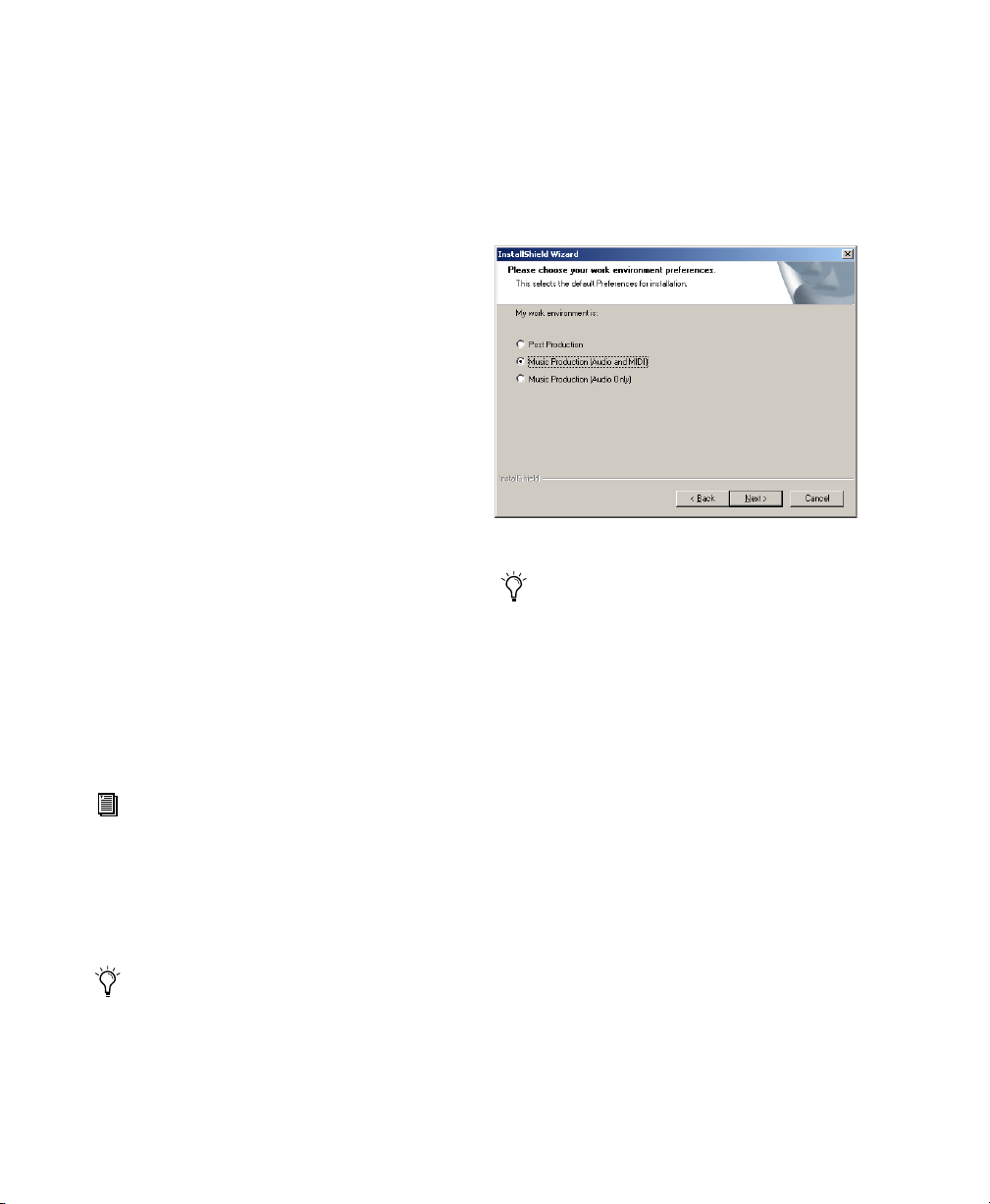
11 Select a “work environment.” This is an ini-
tial set of Pro Tools Preferences. These Preference “sets” have been pre-configured to include
some of the more popular settings for post production, audio, and audio with MIDI. Click
Next.
Selecting a Pro Tools Work Environment
Preference settings can be customized at any
time in Pro Tools. See the
ence Guide
for more information about Pref-
Pro Tools Refer-
erences.
DigiTranslator Enables the exchange of audio
and video files, and sequences between
OMFI-compatible applications and Pro Tools.
For more information on DigiTranslator,
see the DigiTranslator Guide.
Answerbase This component contains standalone Pro Tools multi-lingual information databases. Note that these files require approximately 37 MB of disk space.
MacOpener is included on the Pro Tools installer CD-ROM disk and requires a separate installation process.
10 Click Next.
Getting Started with MIX30
Page 37
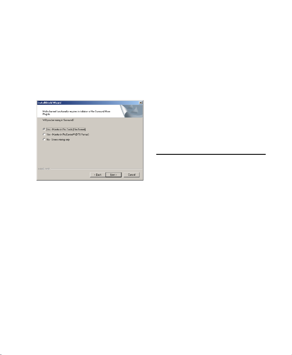
12 Select whether to install the Surround Mixer
plug-in. This plug-in is required for mixing,
mastering, and monitoring in surround. For Surround systems, select Yes – Monitoring Pro Tools
Film Format if your monitoring is configured for
Film Format, or select Yes – Monitoring in ProControl (DTS Format) if using a ProControl dedicated controller. Select No – Stereo mixing only,
if your monitoring is configured for Stereo. After
making a selection, click Next.
Installing QuickTime
QuickTime 5 is required for Pro Tools. Install
the latest version of QuickTime for Windows
(available on the Pro Tools TDM 5.3.1 CD-ROM
or from www.apple.com). Be sure to install the
“Recommended” install of QuickTime or
Pro Tools will not handle QuickTime video correctly.
Using MIDI
Pro Tools in Windows uses your Multimedia
Setup to configure MIDI devices and their properties. Refer to your device’s installation and usage documentation to properly configure the
device.
Checking Your TDM System
and Launching Pro Tools
Selecting a Pro Tools Surround Mixer
13 Wait for the installer to finish installing all
software components, drivers, and PACE System
files before proceeding to the next step.
14 If QuickTime is not already installed, you
will be prompted to install the “Recommended”
QuickTime installer option now (see “Installing
QuickTime” on page 31). Follow the on-screen
instructions to complete the QuickTime installation process.
15 When installation is complete, click Finish to
restart your computer.
If you do not follow the steps above or if you
cancel any of the steps, your computer may not
recognize your Pro Tools cards and you may receive the error message, “Cannot Create DAE
Deck.” To resolve this error message, see “Cannot Create DAE Deck Or Error Number 4” on
page 33.
Before you launch Pro Tools, run the DigiTest diagnostics application located in the Digidesign
Utilities folder (see “Running DigiTest” on
page 32). DigiTest finds your cards and confirms
that they are correctly installed and working.
When DigiTest has completed and you have rebooted your computer, launch Pro Tools for the
first time.
Starting Up Your System
Whenever you start your system, you must turn
on all of your system components in a specific
order.
Start your Pro Tools System in this order:
1 Make sure all your equipment (including your
CPU) is off.
2 For TDM systems with an expansion chassis,
turn on the expansion chassis.
Chapter 3: Windows Configuration 31
Page 38

3 Turn on external hard drives, if any. Wait ap-
proximately ten seconds for them to spin up to
speed.
4 Lower the volume of all output devices, then
turn on your Pro Tools audio interfaces.
5 Turn on any MIDI interfaces and devices, or
synchronization peripherals.
6 Turn on your Pro Tools audio interfaces (such
as 888|24 I/O). On power up, the status LEDs
will flash. Wait at least fifteen seconds for the
audio interface to initialize, and the status LEDs
to stop blinking and stay lit.
If you launch Pro Tools without turning on your
audio interfaces, you will be prompted to turn
them on. Allow fifteen seconds for audio interfaces to power-up and the status LEDs to stop
blinking and stay lit, before clicking OK.
7 Turn on your computer.
Running DigiTest
Run the DigiTest diagnostics application to
identify TDM cards and verify that they are correctly installed and working.
DigiTest is included on the Pro Tools Installer CD and installed with Pro Tools.
DigiTest resides in the Digidesign Utilities
folder located in your hard drive, in the subdirectory Digidesign/Pro Tools/Pro Tools
Utilities.
Before you run DigiTest, lower the volume
of all output devices. Very loud digital noise
may be emitted during the test.
To run DigiTest:
1 Turn off Pro Tools.
2 Go to Start > Programs > Digidesign >
Pro Tools > DigiTest.
3 Test cards.
• To test only one Digidesign card in your system, click the button that corresponds to this
card.
• To test all Digidesign cards at once, press the
“Test All Cards” button.
4 When prompted, recycle power on all
Pro Tools peripherals. Press Continue.
5 Check the “Test I/O Box.”
LEDs on your digital interfaces may light up
during this test. This is normal. Continue to
test.
6 Exit DigiTest by clicking on the “close” box on
the top right hand corner of the application
window.
7 Reboot your computer.
Errors and Undetected Cards
Complete the steps below if:
■ There is a problem with a component in your
system and an error message has been displayed
to the right of the corresponding card’s button
in DigiTest.
– or –
■ A supported card is installed but not automat-
ically detected during DigiTest.
If a supported card is installed and is not
automatically detected:
1 Close DigiTest.
2 Power down your system.
3 Reinstall the cards (see “Installing Pro Tools
Cards” on page 27).
4 Check the card seating.
5 Check the TDM ribbon cable connection.
Getting Started with MIX32
Page 39

6 Power up.
7 Begin DigiTest again.
For descriptions of all error codes, refer to
Appendix B, “DigiTest Error Codes.” For test details, click the Info button to the right of the reported error, then click Failures in the pop-up
window and change Failures to Detailed.
If a card continues to fail DigiTest, contact
Digidesign Technical Support:
tel: 650·731·6100
Congratulations! Pro Tools is launched. When
Pro Tools is launched for the first time only the
menus will appear. To see Edit and Mix windows, a new session must be created. But before
you begin working with Pro Tools, you should
get acquainted with Pro Tools system settings
(see “Configuring Pro Tools” on page 34).
Cannot Create DAE Deck Or Error Number 4
Your computer may not recognize your
Pro Tools cards if you did not correctly follow all
of the hardware and software installation steps.
Launching Pro Tools the First
Time
Validate Pro Tools Software
When launching Pro Tools the first time, you
are prompted to enter an authorization code to
validate your software.
To validate Pro Tools software:
1 Double-click the Pro Tools application in the
Pro Tools folder inside the Digidesign folder.
2 Enter the authorization code in the dialog
when prompted, making sure to observe any
spaces, then click Validate.
Authorization code validation for Pro Tools
The authorization code is located on the inside
cover of this guide.
If you receive error message number 4 or “Cannot Create DAE Deck,” when you launch
Pro Tools, complete the instructions below.
To correct a “Cannot Create DAE Deck” error:
1 Turn your computer off.
2 Confirm that all your Pro Tools cards are
seated correctly and cables are tightly fastened.
3 Start your computer and launch Pro Tools. If
the error does not re-appear, you do not need to
continue with these steps.
4 With your computer on, right-click the My
Computer icon (located on your Widows desktop).
5 Choose Properties > Hardware > Device Man-
ager.
6 Expand the Sound, Video and Game Control-
lers list.
7 In Multimedia Devices, you should see an “!”
icon next to each Pro Tools DSP chips that is not
properly installed.
8 Select one of these “!” icons and press Delete.
Click OK in the Confirm Device Remove dialog.
Chapter 3: Windows Configuration 33
Page 40

9 Repeat the previous step for each of these “!”
icons, until they are all removed. Then, click
OK.
10 You are ready to install your Pro Tools cards.
See “Installing Pro Tools Hardware” on page 25.
Configuring Pro Tools
3 From the CPU Usage Limit pop-up, select the
maximum percentage of CPU resources to allocate to host processing tasks. The default setting
is 40%. Select a higher setting if you need more
host processing power for RTAS, TDM, and Direct Connect applications.
Increasing the CPU Usage Limit may slow
down screen responses.
Configuring the Playback Engine
The Playback Engine sets the voice count (and
voiceable tracks) for your system, and it’s sessions. Additionally, it lets you customize various
System Usage parameters (such as buffers, CPU
Usage).
To configure the Playback Engine:
1 Choose Setups > Playback Engine.
Playback Engine dialog for Pro Tools TDM system
2 From the H/W Buffer Size pop-up, select the
audio buffer size, in samples, for host processing
tasks such as Real-Time AudioSuite (RTAS) plugin processing. The default setting is 512 samples. Select a higher setting if you need more
buffer time for RTAS, TDM, and Direct Connect
applications.
4 From the Number of Voices pop-up, select the
amount of voices (and voiceable tracks), for
your sessions. The default number of voices on a
Pro Tools|24 MIX system is 32 voices.
Changing the number of voices affects DSP
usage and your system performance. Please
read the following carefully.
Depending on the number of MIX Core, MIX
Farm, and DSP Farm cards in your system, you
will have different choices available. For example, each MIX card allows you to use one or two
of its DSPs per card for voicing.
Most DSP amounts support two levels of voice
numbers:
• Select higher voice numbers when your
cards are in your machine. You should also
select higher voice numbers when using a
chassis to run higher track counts at higher
sample rates (such as 64 tracks) and you
want more voices (such as 32 voices per
DSP).
• Select minimum voice numbers when running cards in an expansion chassis, using
other PCI cards along with Digidesign
cards, or if you are running high bandwidth PCI cards (such as video capture).
For voice limits on different MIX systems, refer
to the Pro Tools Reference Guide.
5 Set DAE Playback Buffer Size.
6 Click OK, when finished.
Getting Started with MIX34
Page 41

DAE Playback Buffer Size
The DAE Playback Buffer Size determines the
amount of memory allocated within DAE to
manage disk buffers, which affects system performance.
Though DAE automatically selects the optimal
playback buffer size for your system, you may
want to adjust this parameter to modify your
system’s performance:
◆ Allocating a larger buffer size can sometimes
allow for a higher density of edits. This can be
useful if you experience system performance
problems in sessions with a large number of edits in rapid succession. However, choosing a
larger buffer size can cause a time lag to occur
before playback or recording begins. It can also
cause a time lag to occur when you are editing
during playback.
◆ Allocating a smaller buffer size can sometimes
improve playback/recording initiation speed.
This can be useful if you are experiencing a time
lag when you initiate playback/recording. However, choosing a smaller buffer size can make it
difficult for slower hard drives to play or record
tracks reliably.
Configuring Hardware Setup
(Audio Interfaces)
Pro Tools MIX peripherals support 8 channels of
simultaneous I/O. The peripherals support multiple formats (such as analog, AES/EBU, and so
on).
Hardware Setup dialog for 888|24 I/O
The Hardware Setup dialog provides controls for
hardware Sample Rate, Clock Source, and operating levels. This dialog will display different
controls depending on the audio interface selected in the Interface pop-up menu.
To properly configure connected peripherals for
use with Pro Tools, you must select the peripheral, then set the parameters for the selected peripheral—repeating this for each peripheral in
your system.
Use the Up and Down Arrow keys to scroll
though each peripheral.
To validate audio interfaces with the Identify
button:
1 Choose Setups > Hardware in Pro Tools.
2 From the Peripherals list, select the Digidesign
audio interface connected to the first card in
your MIX system. This will be the interface at
the top of the list.
3 If “no interface” appears in the Peripherals
list, use the Interface pop-up menu to manually
identify the audio interface.
Chapter 3: Windows Configuration 35
Page 42

4 Click on the Identify button, located in the
lower left corner of the Hardware Setup dialog,
to illuminate all the LEDs on the front panel of
the audio interface. If the LEDs do not light,
make sure the interface is selected in the Peripherals list, and that it is powered on. If the LEDs
continue to not light, review hardware installation and run DigiTest again.
5 Repeat the above steps for additional audio in-
terfaces.
To configure audio interfaces:
1 Choose Setups > Hardware in Pro Tools.
2 From the Peripherals list, select the Digidesign
audio interface connected to the first card in
your MIX system. This will be the interface at
the top of the list.
3 From the Clock Source pop-up menu, select
the appropriate clock source for the system. In
most cases, you will use Internal. The other
choices are for resolving Pro Tools to external
clock sources. Depending on your audio interface, Clock Source options can include:
AES/EBU, S/PDIF, Optical, AES/EBU 1–8, and
Word clock.
4 From the Clock Source pop-up menu, select
the appropriate clock source for devices attached to your I/O.
5 Configure controls specific to your MIX I/O.
6 For additional MIX-series I/Os, choose the I/O
in the Peripherals list, and repeat the above
steps.
Configuring 888|24 I/O Controls
To configure controls specific to an 888|24 I/O:
■ With the 888|24 I/O selected in the Peripher-
als list, you can configure the following options:
• Channel pairs can be set to Analog or Digital.
• You can set the sensitivity of the Output
Meter Levels.
• You can set Peak Hold to Off or Normal.
• You can turn off or enable DAC Muting.
Hardware Setup dialog for 888|24 I/O
Configuring 882|20 I/O Controls
To configure controls specific to an 882|20 I/O:
■ With the 882|20 I/O selected in the Peripher-
als list, you can configure the following options:
• You can set your Input and Output levels
by selecting Reference Level +4 dBu or
–10 dBV.
• Channels 1 and 2 can be set to Analog or
Digital.
• You can set the S/PDIF Format for Tascam
DA-30 or Other.
Getting Started with MIX36
Page 43

Hardware Setup dialog for 882|20 I/O
Configuring 1622 I/O Controls
To configure controls specific to an 1622 I/O:
■ With the 1622 I/O selected in the Peripherals
list, you can configure the following options:
• You can set your Input levels by using
channel fader controls with a Reference
Level range of +4 dBu to –10 dBV.
• You can set your Output levels by selecting
Reference Level +4 dBu or –10 dBV.
• Channels 1 and 2 can be set to Analog or
Digital.
• You can set the S/PDIF Format for Tascam
DA-30 or Other.
Configuring I/O Setup
The I/O Setup dialog provides a graphical representation of the Hardware Setup. Each I/O attached to your system is displayed, with controls to route physical ports to Pro Tools inputs
and outputs. The I/O Setup dialog also lets you
label and map Pro Tools input, output, insert,
and bus signal paths.
I/O Setup dialog with a single 888|24 I/O
Pro Tools ships with default I/O Setup settings
that will get you started. You only need to go to
I/O Setup if you want to remap or rename the
default I/O paths.
Hardware Setup dialog for 1622 I/O
Configuring ADAT Bridge I/O Controls
For information on configuring the Hardware
Settings for the 24-Bit ADAT Bridge I/O or the
original ADAT Bridge I/O, please refer to the
ADAT Bridge I/O Guide.
To configure I/O routing in I/O Setup:
1 Choose Setups > I/O Setups in Pro Tools.
2 Map and name paths as desired.
3 If necessary, redefine formats for I/O channels
of any peripherals.
Refer to the Pro Tools Reference Guide for
more information on setting up I/O paths.
Chapter 3: Windows Configuration 37
Page 44

Getting Started with MIX38
Page 45

chapter 4
Connecting Your Studio
This chapter provides general information on
connecting Pro Tools to your system, including
digital equipment, effects units, MIDI gear, and
SMPTE synchronization devices.
Refer to the 888|24 I/O Guide, the 882|20 I/O
Guide, the 1622 I/O Guide, or the ADAT
Bridge I/O Guide for specific details regarding:
• Front and back panel connectors and indicators
• Technical specifications
Setting Up Your Studio
The following diagrams provide general suggestions for connecting studio gear to your system.
Figure 1 illustrates a typical studio setup, with
an 888|24 I/O connected to a mixing console,
effects and other equipment.
The 888|24 I/O analog audio connectors
are balanced XLRs with pin 2 wired hot
(or “+”), pin 3 cold (or “–”), and pin 1
ground.
If you are connecting a balanced system, pin
1 and shield should be connected at the input only (not at the output). This will prevent ground loops between the shield and
pin 1 conductor.
If you are connecting an unbalanced signal
to the 888|24 I/O inputs or outputs, connect
only pin 2 to the “+” signal, and pins 1 and
3 to ground at all inputs only.
Figure 2 illustrates a setup without a mixer,
where effects and monitoring gear are connected directly to an 882|20 I/O.
Chapter 4: Connecting Your Studio 39
Page 46

Example Studio Setup with a Mixing Console
1
3
T
U
2
P
5
N
I
G
O
L
A
N
A
4
7
6
1
8
3
T
U
P
T
2
U
5
O
G
O
L
A
N
A
4
7
6
8
Analog
Inputs 5-8
Analog
Audio
Outputs 5-8
/
1
P
T
6
U
/
5
O
U
B
E
/
S
E
A
/
3
8
/
7
Audio
Digital Inputs/Outputs
Channel 1-2
To DAT Recorder
1
r
e
t
u
p
m
o
C
2
r
e
t
u
p
m
o
C
e
d
2
o
/
1
M
H
e
C
d
8
o
M
T
U
4
D
P
/
S
N
I
H
U
C
P
6
/
4
N
5
I
x
2
U
B
E
/
S
E
4
A
/
3
2
8
/
T
7
K
C
O
L
C
E
V
A
L
S
K
T
C
U
O
O
L
C
E
V
A
L
S
N
I
F
I
D
P
/
S
F
I
T
U
O
Digital Inputs/Outputs
Channel 3-4
To Digital Effects Devices
DAT Recorder
Effects Devices
Tape Returns
or Inputs 1-4
Instruments
Connected to Console
Outputs 1-4
Figure 1. Typical studio configuration using an 888|24 I/O
Channel
Digital Effects Devices
Power Amp
and Speakers
Getting Started with MIX40
Page 47

Example Studio Setup without a Mixing Console
Mic Preamp,
Direct Box, Synth, etc.
Analog
Audio
Inputs 1-2
INPUTS
G
ALO
AN
2345678
1
Analog
Audio
Outputs 1-2
TS
UTPU
O
G
ALO
AN
123456
Analog
Audio
Inputs/Outputs
3-8
78
IN
T
U
O
LO
VE C
SLA
Power Amp
and Speakers
S/PDIF Digital Input/Output
To DAT Recorder
COMPUTER
IN
T
U
O
IF
D
/P
S
K
C
DAT Recorder
Effects Devices
Figure 2. Typical studio configuration without a mixer using an 882|20 I/O
Chapter 4: Connecting Your Studio 41
Page 48

Connecting Equipment with Digital Audio Ins and Outs
Because the 888|24 I/O, 882|20 I/O, 1622 I/O,
and 24-Bit ADAT Bridge I/O feature digital inputs and outputs, Pro Tools allows you to digitally record to or from a digital device such as a
DAT recorder. The 888|24 I/O and 24-Bit ADAT
Bridge I/O provide both AES/EBU and S/PDIF
digital audio input and output. The 882|20 I/O
and 1622 I/O provide S/PDIF digital audio input
and output.
If you plan to use a DAT player, CD recorder, or
other digital input and output device with your
Pro Tools system, be sure the external device
supports either the AES/EBU or S/PDIF format.
Your interface’s AES/EBU inputs and outputs
should only be connected to another AES/EBU
device. Likewise, its S/PDIF inputs and outputs
should only be connected to another S/PDIF device.
To connect your Pro Tools system to a DAT
recorder:
1 Connect the digital output (AES/EBU or
S/PDIF) of the audio interface to the digital input (AES/EBU or S/PDIF) of the DAT deck. Audio
channels 1 and 2 will be sent out of these outputs.
2 Connect the digital output (AES/EBU or
S/PDIF) of the DAT to the digital input (AES/EBU
or S/PDIF) of the audio interface. The DAT recorder will be routed to Pro Tools inputs 1 and 2.
For information on using an ADAT with
Pro Tools, see the ADAT Bridge I/O Guide.
Connecting Effects Units
The 888|24 I/O, 882|20 I/O, 1622 I/O, and 24Bit ADAT Bridge I/O audio interfaces allow you
to connect effects units to your system by using
any analog or digital inputs and outputs as Auxiliary Inputs and Outputs for effects sends and
returns. Once an effects unit is attached this
way, you can send a variable amount of a track’s
output to the effects unit using a send fader in
Pro Tools.
Five separate send controls on each Pro Tools
track allow you to route audio to any of the
available outputs connected to your system or
through any of the 32-internal busses in the
Pro Tools TDM Mixer. Outputs can be returned
to mono or stereo Auxiliary Inputs for automated mixing or processing.
When you are using an effect in this send-type
of configuration, make sure the unit’s internal
mix or balance between direct (unprocessed)
and wet (effected) signal is set so that only the
processed signal is returned to Pro Tools. On
most effect units, a balance setting of 100%
(completely wet) is the appropriate setting.
If you’ve been using an effects unit in an instrument setup, such as a guitar effects rack, you’ll
probably find the balance to be below 50%. If
the unit has separate dry and effect level knobs,
turn dry level control off. If you don’t do this,
the dry, unprocessed signal will be present in an
effect’s output along with the desired processed
sound, and you’ll have trouble accurately controlling the effect balance in your final mix.
Getting Started with MIX42
Page 49

Connecting Effects Units Digitally
To use your audio interface’s inputs and outputs
as effects sends & returns to a digital effects device, set your interface to Internal mode (unless
it is already synchronized to an external clock
source such as a DAT deck). You should then set
your digital effects devices to accept an external
digital clock so that they will synchronize themselves to Pro Tools. In the Pro Tools Hardware
Setup dialog, set the input of the channel pair to
which you have connected the digital effects device to Digital, and set the Sync Mode to Internal.
Connecting MIDI Devices
Macintosh
By adding a Macintosh-compatible MIDI interface to your system, you can take advantage of
all the MIDI features of Pro Tools, including recording and editing tracks, syncing to MIDI
Time Code or MIDI beat clock (this requires an
appropriate MIDI interface) and the use of MIDI
Controllers.
For information on configuring a MIDI control surface for use with Pro Tools, see the
Pro Tools MIDI Control Surfaces Guide.
To connect MIDI devices to your system:
1 Connect the MIDI interface to your computer
according to the MIDI interface’s documentation.
On 9600, 9500, and Beige G3 Power Macintosh computers, connect the MIDI interface to the modem port. MIDI timing data
output through the modem port is more accurate than that output through the printer
port.
2 Install any MIDI driver software required by
the MIDI interface. (Once you have installed
your MIDI interface hardware and software,
confirm that it is working properly using the
procedure given in the interface’s documentation.)
3 Connect the MIDI OUT of your MIDI device
or controller to the MIDI IN of your MIDI interface.
4 Connect the MIDI IN of your MIDI device or
controller to the MIDI OUT of your MIDI interface.
See Appendix C, “Configuring OMS (Macintosh Only)” for information on configuring OMS (Open Music System) software,
which is required for Pro Tools and MIDI
on the Macintosh.
Windows
By adding a Windows 2000-compatible MIDI interface to your system, you can take advantage
of all the MIDI features of Pro Tools, including
recording and editing tracks, syncing to MIDI
Time Code or MIDI beat clock (this requires an
appropriate MIDI interface) and the use of MIDI
Controllers.
For information on configuring a MIDI control surface for use with Pro Tools, see the
Pro Tools MIDI Control Surfaces Guide.
To connect MIDI devices to your system:
1 Connect the MIDI interface to your computer
according to the MIDI interface’s documentation.
Chapter 4: Connecting Your Studio 43
Page 50

2 Install any MIDI driver and/or controller soft-
ware required by the MIDI interface. (When
your MIDI interface hardware and software is installed, confirm that it is working properly. To
do so, use the procedure provided with the interface’s documentation.)
3 Connect the MIDI OUT of your MIDI device
or controller to the MIDI IN of your MIDI interface.
For fairly short pieces of audio program material, SMPTE Trigger is acceptable, especially if
the sync master has a fairly stable transport or is
resolved to house sync or a black burst generator. In this case, the master transport and
Pro Tools will probably not drift very far apart in
such a short period of time.
Trigger Sync for Audio Post Applications
(recommended for short duration audio regions)
4 Connect the MIDI IN of your MIDI device or
controller to the MIDI OUT of your MIDI interface.
Connecting SMPTE Synchronization Devices
If you intend to synchronize Pro Tools to external devices with SMPTE using MIDI Time Code,
your system must be connected properly. This
section provides setup suggestions for synchronizing Pro Tools to audio or video tape. For details on SMPTE and synchronization, see the
Pro Tools Reference Guide.
Pro Tools and Synchronization
Pro Tools supports a type of SMPTE synchronization known as SMPTE Trigger through the use
of SMPTE-to-MIDI Time Code converters. This
type of synchronization allows Pro Tools to
chase and start (or stop) playback and recording
while slaved to other systems. With SMPTE Trigger alone, once playback or recording starts,
there is no further synchronization, and
Pro Tools will play back at a rate determined by
the internal clock of the audio interface or selected external clock source.
Video Tape Recorder
VITC Video out
OR
SMPTE
LTC and VITC to MIDI Time
Code Convertor
Composite
Video out
RGB Monitor
MIDI Time
Code out
MIDI Interface
to computer
Computer
Computer
Monitor
Synchronization setup using SMPTE Trigger alone
On the other hand, if the audio piece is several
minutes long, or if the sync master has an unstable transport (as in the case of a low quality recording deck striped with SMPTE, for example),
SMPTE Trigger alone is probably not an acceptable solution, since the two systems may drift
apart noticeably over the duration of the source
material.
A better alternative is to use Digidesign’s
SYNC I/O or Universal Slave Driver (USD).
Getting Started with MIX44
Page 51
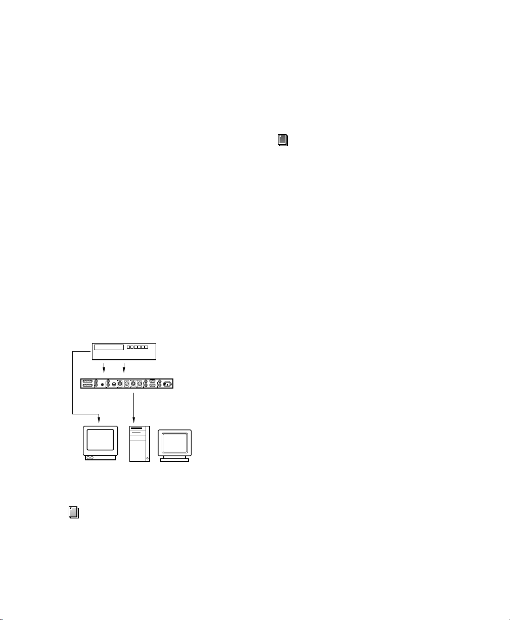
The Digidesign Universal Slave Driver
The Universal Slave Driver (USD) is a multi-purpose synchronization peripheral that provides
virtually all of the functions and connections
needed to achieve synchronization to a variety
of devices.
The USD allows synchronization of Pro Tools to
Linear Time Code (LTC), VITC, and BiPhase/Tach while resolving to a video house reference or other word clock signals. It supports
all major industry-standard clocks and formats
and can also act as a standalone MIDI Time
Code (MTC) or VITC reader/generator.
In addition, the Universal Slave Driver offers extremely fast lockup, near-sample accurate synchronization, and an exceptionally low-jitter
clock. These features provide professional performance and maximum audio fidelity under a
wide range of synchronization conditions.
LTC or VITC-locked Sync for music/audio applications
with Digidesign’s Universal Slave Driver
(for resolving to LTC or VITC)
SYNC I/O
The SYNC I/O can be used with
Pro Tools|24 MIX and Pro Tools|24 systems, as
an alternative to the USD. When used with
Pro Tools|24 MIX and Pro Tools|24 systems, the
SYNC I/O emulates the USD.
For information on using the SYNC I/O, see
the SYNC I/O Guide.
Video Tape Recorder
SMPTE
BI-PHASE / TACH / GPI
PC SERIAL
Composite
Video out
VIDEO REF
RGB Monitor
OR
IN
L
T
C
OUT
I
N
MAC SERIAL
VIDEO
MTC OUT
VITC Video out
L
A
T
E
C
S
O
I
U
N
T
A
IN
IN
E
S
9-PIN IN / ACC
O
OUT
OUT
U
T
SUPER CLOCK (256X)
WORD CLOCK
9-PIN OUT
serial output
direct to
MIX or d24 card's
DigiSerial port
85-264VAC, 47-63HZ, 115 W
Computer Computer
Digidesign Universal Slave Driver
Monitor
Synchronization setup using a USD
For information on using the Digidesign
Universal Slave Driver, see the Digidesign
Universal Slave Driver Guide.
Chapter 4: Connecting Your Studio 45
Page 52

Getting Started with MIX46
Page 53
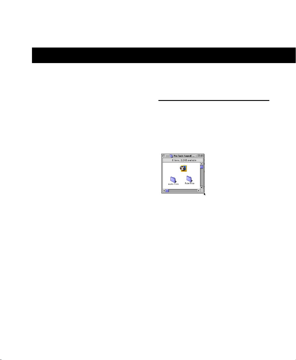
chapter 5
Working with Pro Tools
This chapter takes you on a guided tour of
Pro Tools, introducing its main windows and
features. Also included is a step-by-step overview of basic audio recording (see “Basic Recording” on page 57).
How to Use This Chapter
If you are new to Pro Tools, read this chapter for
an overview of how to get started learning to
record, edit, automate, and mix using
Pro Tools|24 MIX.
All of the features described in this chapter are
explained fully in the Pro Tools Reference Guide.
Refer to that guide, using its index, to find additional information on all Pro Tools features.
Session Basics
Pro Tools projects are created and saved as sessions. Sessions store all tracks, audio, MIDI, and
other session information. Audio and fade files
are stored in folders within the session folder.
Session folder, containing the session file and its Audio
Files and Fade Files folders
Pro Tools remembers audio interface configuration and other system settings and applies them
to all new sessions.
Chapter 5: Working with Pro Tools 47
Page 54
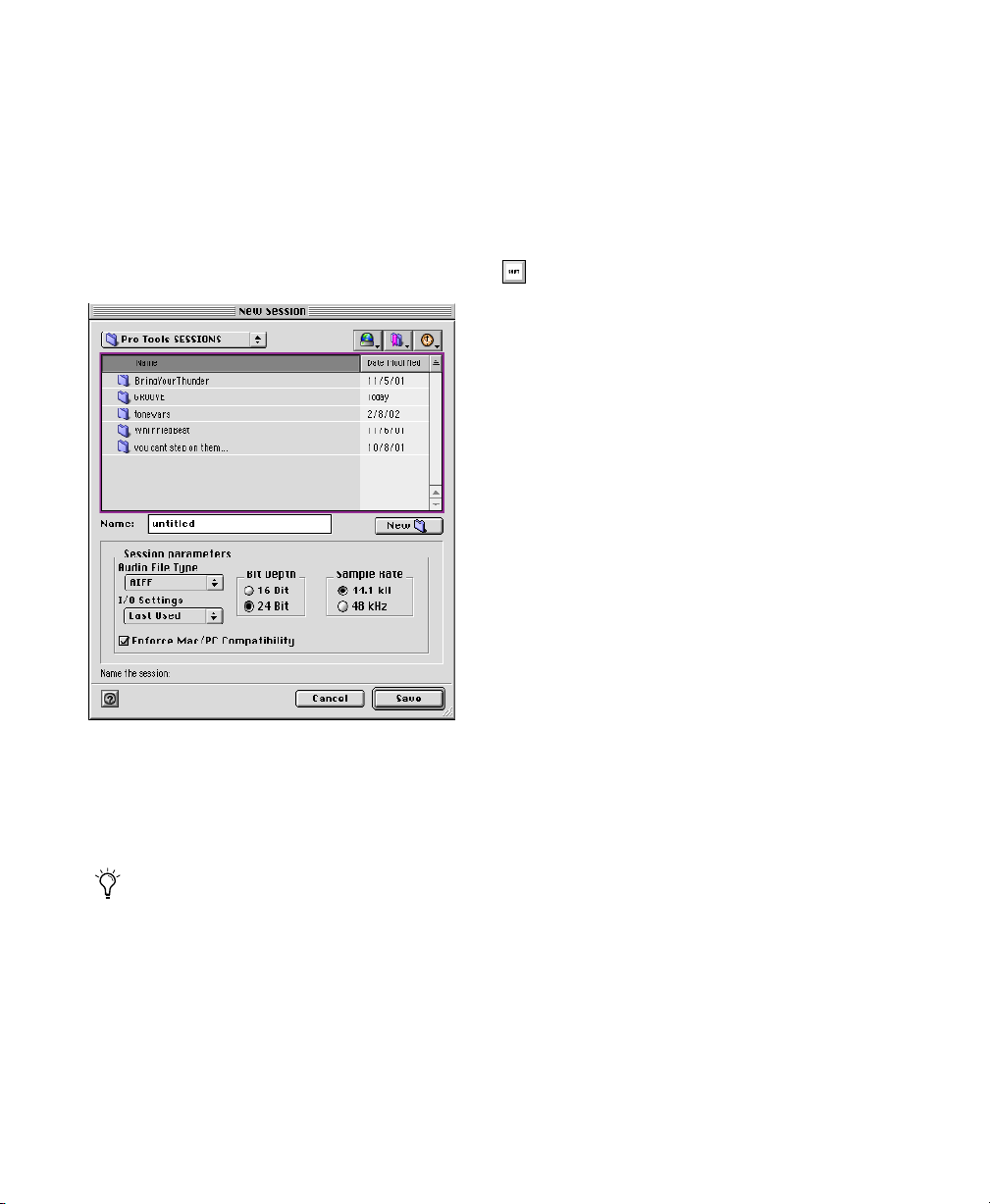
Starting a Session
Main Windows
The basic steps to set up a new session are:
1 Launch Pro Tools.
2 Choose File > New Session.
3 In the New Session dialog, set sample rate, bit
depth, and other options for the new session.
New Session dialog
4 Select where you want to save your session. If
using external hard drives with your Pro Tools
system, make sure you select the appropriate
drive in the New Session dialog.
The Mix, Edit, and Transport windows are the
main Pro Tools work areas (see Figure 3 on
page 49). You can show (or hide) any of these
windows by choosing show (or hide) commands
in the Windows menu.
Use Command+”=” on Macintosh, or
Ctrl+”=” on Windows, to quickly switch
between the Edit and Mix windows.
Mix Window Displays the Pro Tools mixer, with
its familiar fader strip controls for track level,
pan, solo, mute, and signal routing.
Edit Window Displays tracks in the session along
the Timeline, for editing of audio, MIDI, and automation data.
Transport Provides standard transport controls
for Play, Stop, Rewind, Fast-Forward, Pause, and
Record. The Transport window can also show
Counter and MIDI Control displays.
Session Setup Provides status display for important Pro Tools session settings, including sample and frame rate, clock source, and file format.
Also includes the Current Time Code counter,
and controls for clock reference, positional reference, and other time code features for the
Digidesign Universal Slave Driver (USD).
Enable Enforce Mac/PC Compatibility to
ensure cross-platform compatibility for your
new session.
5 Type a name for your session.
6 Choose Save. The new session opens its Mix,
Edit, and Transport windows (see Figure 3 on
page 49).
Getting Started with MIX48
Page 55

Timebase
Rulers
Tracks
Edit window
Mix window
Regions
Lists
Transport
Figure 3. Main session windows (Macintosh shown)
Session Settings
Pro Tools provides several different Timebase
Rulers to select the timebase for your session.
Timebase Rulers, displayed along the top of the
Edit window, include Bars:Beats, Minutes:Seconds, Time Code, Feet.Frames, and Samples.
The current Timebase determines the format of
your main counters, and provides the basis for
the Edit window Grid.
For post production, select either Time Code or
Feet.Frames as your session Timebase in the Rulers view.
To select a Timebase Ruler:
■ Click the circle next to the displays at the top
left side of the Edit window (labeled Bars:Beats,
Time Code, Min.:Sec, and so on).
Tracks
Session Setup
Tempo
You can set a session tempo using the MIDI
tempo controls in the expanded Transport window, or using the Tempo ruler.
To define your session tempo:
■ Click in the Tempo field in the Transport win-
dow, and type in the desired tempo.
To tap in a session tempo:
1 Choose Display > Transport Window Shows >
MIDI Controls.
2 In the Transport MIDI controls, turn off the
Conductor to enable Manual Tempo mode.
3 Use the mouse to click on the Tap button.
Chapter 5: Working with Pro Tools 49
Page 56
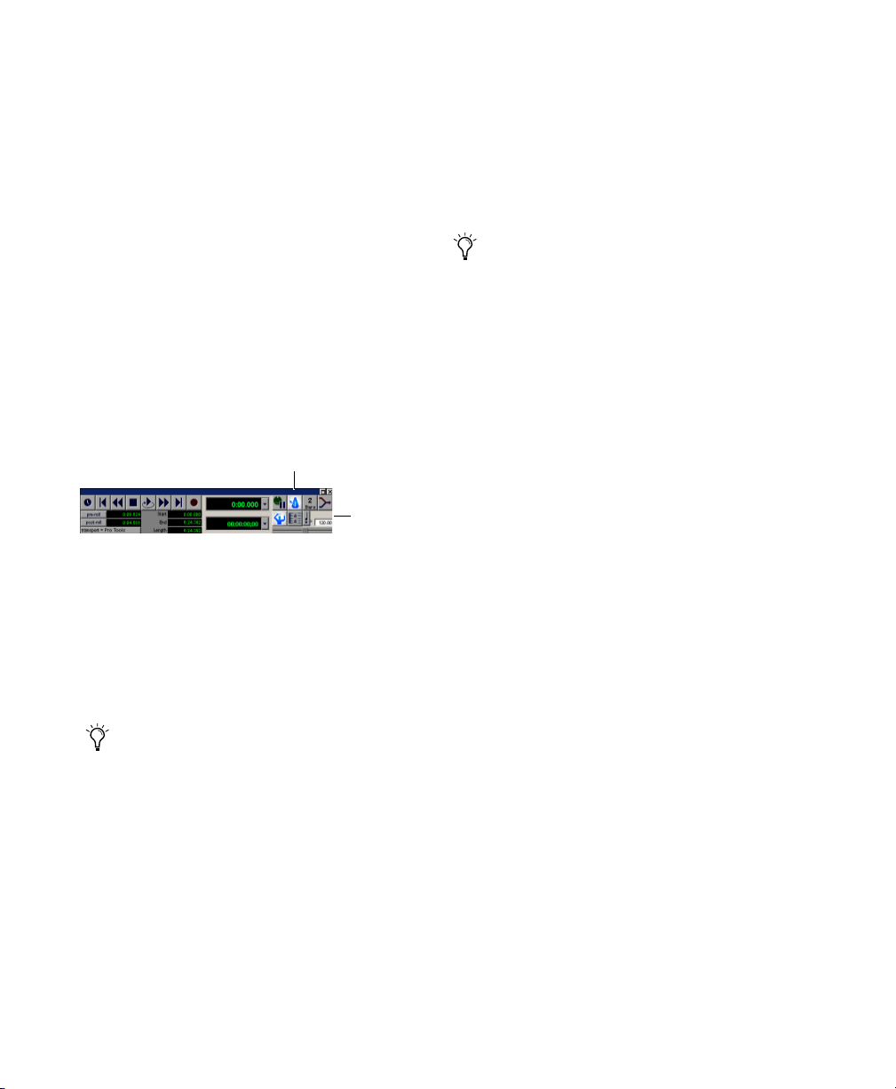
Click and Metronome
Pro Tools provides its own MIDI Click options.
This feature can be turned on and off using the
Metronome icon in the Transport window, and
is configured from the MIDI Click Options dialog.
Saving Sessions
As you build a session by adding tracks, changing session parameters, and so forth, you will
want to save your work. Pro Tools provides
three ways to save sessions, with each providing
a different set of options.
To configure and enable the Pro Tools click:
1 Choose MIDI > Click Options.
2 Configure the click parameters as needed for
your MIDI sound source in the Click/Countoff
Options dialog.
3 During recording or playback, you can turn
the Click on or off using the Click switch in the
Transport window, MIDI Controls display.
Metronome
Tempo
Controls
Transport window, displaying Click and Tempo Controls
Frame Rate and Other Synchronization Settings
To set session frame rate or other synchronization
settings:
1 Choose Windows > Show Session Setup.
2 Set parameters as desired.
If you are using an Ethernet or MIDI control
surface, or an external synchronization peripheral, choose Setups > Peripherals, then
select MIDI Controllers or Ethernet Controllers, as appropriate, and enable each device.
For more information, refer to the guide for
your control surface or the MIDI Control
Surfaces Guide.
Saving sessions is most often performed for
data security, archiving, and in preparation
for transferring projects. In addition, session
files can be saved in order to perform sample
rate conversion, or even to create session
templates. Session templates are Pro Tools
sessions that have tracks, routing, plug-ins,
or any other parameters predefined. See the
Pro Tools Reference Guide for more information about how to create and use session
templates.
To save a session:
■ Choose File > Save Session, Save Session As, or
Save Session Copy In.
Save Session Saves the currently open session as
is, leaving it open to continue working.
Save Session As Creates a duplicate session file
with the name you choose. It does not create a
new Audio Files or Fade Files folder. This can be
useful if you want to experiment with different
arrangements in the session without affecting
the original session.
Save Session Copy In Only saves the files that
you are using in the current session. This can be
useful for creating a final copy of the session
that does not include audio files or fades you are
no longer using.
Getting Started with MIX50
Page 57
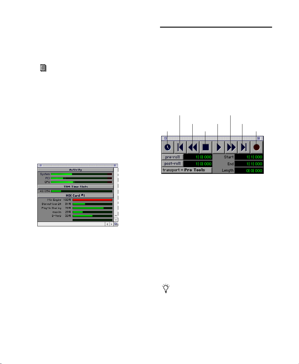
System Resources and Settings
You can customize many Pro Tools system settings in the Playback Engine dialog to optimize
system performance.
For information on configuring the Playback Engine on Macintosh, see “Configuring Pro Tools” on page 17.
For information on configuring the Playback Engine on Windows, see “Configuring
Pro Tools” on page 34.
System Usage Window
Displays information on CPU and DSP performance. The System Usage window is especially
useful for monitoring your system’s performance when using RTAS or TDM plug-ins.
Transport Controls
The Transport window provides all Pro Tools
transport commands. There are different available transport controls that can be displayed or
hidden by selecting or deselecting them in the
Transport Window Shows sub-menu.
To show the Transport window:
■ Choose Window > Show Transport Window.
Return To Zero
Rewind
Online
Transport window
Stop
To configure the Transport window:
■ Choose Display > Transport Window Shows
and select the desired view options.
Play
Fast Forward
Go to End
Record
Meters in the System Usage window (TDM shown)
To view system resources and usage:
■ Choose Windows > Show System Usage.
In standard view, the Transport window provides Play, Stop, and other standard transport
controls. The Expanded Transport window provides pre- and post-roll, start, end, and length
indicators for Timeline selection, as well as the
Transport Master selector. The Transport window can also display the following MIDI Controls: Wait for Note, Click, Countoff, MIDI
Merge, Conductor, Meter, and Tempo.
Pro Tools starts playing from the location of
the cursor, or from the beginning of the current selection. The current setting of the
Link Edit/Timeline command in the Operations menu also affects playback. See the
Pro Tools Reference Guide for more information.
Chapter 5: Working with Pro Tools 51
Page 58

Navigating
Pro Tools provides many ways to navigate in a
session, including using the mouse or entering a
location into one of the counters.
To go to a stored memory location:
■ Press the Decimal key on the numeric keypad,
followed by the marker number, followed by the
Decimal key.
To navigate to a location in the Edit window:
■ Click at the desired location with the insert
bar.
Click in a track, or on a Timebase ruler
Navigating in the Edit window
To navigate using the counters:
■ Click in the Main counter and enter the de-
sired location using your computer keyboard.
Click and enter a location into either counter
Navigating in the Counter
Memory Locations
Memory locations provide another way to navigate within sessions.
To define a memory location:
■ Press the Enter key on the numeric keypad
while stopped or during playback. The New
Memory Location window appears, in which
you can define a marker, store a selection, or
store any combination of the other available settings. These settings include track height, group
enables, pre- and post-roll values, and track
Show/Hide. Choose settings for the marker and
click OK.
Tracks
Pro Tools lets you create audio and MIDI tracks
as needed, for audio and MIDI recording, submixing, routing, automating, and editing.
Pro Tools provides four types of tracks: Audio
Tracks, Auxiliary Inputs, Master Faders, and
MIDI Tracks. Audio Tracks, Auxiliary Inputs,
and Master Faders can be mono, stereo, or any
of the supported multichannel formats for surround mixing.
Audio Tracks Record and play back audio to and
from hard disk, monitor audio input when
record-enabled, and edit audio regions.
Auxiliary Inputs Audio mixer channels, used for
input, routing, and submixing.
Master Faders Provide master channel controls
and options for any Output or Bus path.
MIDI Tracks Record, play back, and edit MIDI
data.
To create a new track:
1 Choose File > New Tracks.
New Track dialog
Getting Started with MIX52
Page 59

2 Specify the number of tracks, track type (Au-
dio Track, Aux Input, Master Fader, or MIDI
Track), and mono, stereo, or any of the supported multichannel formats for surround mixing (except for MIDI).
3 Click Create.
Tracks in the Mix window
Audio, Auxiliary Input, Master Fader, and MIDI
tracks appear as vertical channel strips in the
Mix window. Track type is indicated by the
Track Type icons, just below the faders.
Audio Tracks
All audio tracks—whether audio (disk) tracks,
Auxiliary Inputs, or Master Faders—share many
identical controls. Figure 4 on page 54 shows
the Channel controls found in the Mix window
for a stereo audio or Auxiliary Input track. Master Fader tracks do not provide all the controls of
an audio track, such as Sends, Pan, or Record Enable, Mute and Solo buttons.
MIDI Tracks
MIDI tracks provide track level, solo, and mute,
in addition to MIDI input, output, channel, and
program (patch) controls. MIDI volume, mute,
and pan can also be automated using Pro Tools
automation features (see “Mix Automation” on
page 66 for more information).
Adjusting the Volume and Panning of a Track
To adjust the volume of a track:
■ Click the Volume fader on the channel strip of
an audio or MIDI track and move it up or down
to increase or decrease volume.
Audio
Aux
Input
Tracks in the Mix window
Master
Fader
MIDI
To adjust panning of a track:
■ Click the Pan slider on the channel strip of an
audio or MIDI track and drag it to the left or
right to pan the track left or right in the mix.
Chapter 5: Working with Pro Tools 53
Page 60

Record
Solo
Group enable
Inserts
Sends
Input
Output
Volume
Pan
Automation mode
Voice Selector
Mute button
Pan slider
Open Output window
Volume fader
Figure 4. Stereo audio track in the Mix window
Clipping indicator
(lights red)
Level meters (stereo)
Track name
Tracks in the Edit Window
In the Edit window, tracks are displayed horizontally along the Timeline. The area in which
audio appears for each track is the Playlist.
Timeline
Rulers View
Audio Track
Timeline Rulers and a stereo Audio track in the Edit
window
Audio, Auxiliary Input, Master Fader, and MIDI
tracks can be automated. (See “Mix Automation” on page 66 for more information.)
Getting Started with MIX54
Page 61

Viewing and Zooming
When viewing tracks in the Edit window, you
can adjust the height of tracks as well as zoom in
vertically and horizontally using the Track
Height selector and Zoom tools.
Zoom buttons
Zoom presets
Zoom and Track Height tools in the Edit window
Track Height Selector
Zoomer
To zoom in or out, incrementally:
■ Click the appropriate Zoom button.
• Left Arrow (Horizontal Zoom Out)
• Right Arrow (Horizontal Zoom In)
• Waveform and MIDI buttons, to increase or
decrease vertical zoom of the appropriate
track type (audio, or MIDI)
Pro Tools also provides five Zoom preset buttons. You can use these to immediately return to
established zoom levels (you can define the
magnification level for each preset, on a sessionby-session basis).
To use a stored Zoom preset:
■ Click the appropriate Zoom preset switch 1–5.
To store a new Zoom preset definition:
■ Command-click a Zoom preset number to
store the current horizontal and vertical Zoom
to that preset.
To change track height:
■ Click the Track Height Selector, and select a
view size for the track.
You can apply many commands, including
changing the track height selection, to more
than just a single track. Hold down the Option key (Macintosh) or Alt key (Windows)
while performing the operation to apply it to
all tracks; or hold down both the Shift and
Option keys (Macintosh) or Shift and Alt
keys (Windows) while performing the operation to apply it to all selected tracks.
To Zoom in on any area of a track in the Edit
window:
1 Click to select the Zoomer.
2 Click or drag with the Zoomer to zoom in hor-
izontally for a track or Ruler.
Using Memory Locations for Zoom Control
Pro Tools Memory Locations let you store many
attributes with each marker or memory location, including Track Height and Zoom Settings.
By creating Memory Locations that are neither
Markers or Selections, but have Track Height,
Zoom Settings, or other options enabled, you
can use Memory Locations to zoom in and out
using just the numeric keypad.
Chapter 5: Working with Pro Tools 55
Page 62

Regions Lists
Importing Audio
All regions that are recorded, imported, or created by editing appear in the Audio and MIDI
Regions Lists. Regions can be dragged from either list to tracks and arranged in any order. Regions can also be auditioned from the Regions
List by Option-clicking (Macintosh) or Alt-clicking (Windows) them. The Regions List pop-up
menus provide several useful features for managing regions and files (such as, Sorting, Import
Audio, Clear Selected, Rename Selected, Export
Selected As Files, and so on).
Drag to resize width of
Regions Lists
Click to hide
Regions Lists
Audio and MIDI Regions Lists
Click for pop-up menus
Drag to resize
height of Regions
Lists
For information on the Regions List, refer to
the Pro Tools Reference Guide.
Pro Tools lets you import existing audio files
from disk, as well as import tracks from an audio
CD (Macintosh only), into the Regions List or
directly to new tracks. This is very useful if you
are working with sample libraries or you have
audio files you’ve already recorded to disk that
you want to use in a new session.
Selected Region
in a track and in the Regions List
Selected audio region on a track and in the Regions List
To import audio files or regions from disk:
■ Use File > Import Audio to Track to import
files and regions to separate audio tracks (they
will also appear as regions in the Audio Regions
List).
– or –
Use Import Audio from the Audio Regions List
to import files and regions to only the Audio Regions List.
To import a CD audio track (Macintosh Only):
1 Insert the audio CD into your CD-ROM drive.
2 Choose Movie > Import Audio From Other
Movie.
3 Locate and select the audio track to be im-
ported, then click Convert.
Getting Started with MIX56
Page 63

4 When the Save dialog appears, click the Op-
tions button.
5 In the Options dialog, select the sample rate,
bit resolution, and stereo format.
6 At the bottom of the Options dialog, set the
range of the audio track to be imported by adjusting the Start and End times, then click OK.
7 To audition a selected file or region before you
import it, use the Play and Stop buttons.
8 Specify the destination folder for the selected
converted audio file and click Save. Pro Tools
imports the CD audio track as a QuickTime
movie and writes it to your hard drive.
9 When the Track Import window appears, click
OK.
Pro Tools converts the audio track to your session’s sample rate and bit resolution and imports the selected audio tracks into the Audio
Regions List. From there you can drag the regions to existing tracks.
2 Create a new track to record on by choosing
File > New Track. Select 1 Mono Audio Track and
click Create.
3 In the Mix window, find the track I/O con-
trols. If it is not already visible, select Display >
Mix Window Shows > I/O View. The I/O View is
located below the sends and above the solo and
mute buttons.
4 Click the Input button of the new track.
5 From the pop-up menu, select the input you
want recorded. For example, specify A 1 if your
audio source is plugged into analog input 1. The
menu displays the names of the inputs defined
in the I/O Setup dialog (see “Configuring I/O
Setup” on page 20 for Macintosh and “Configuring I/O Setup” on page 37 for Windows).
Basic Recording
This section describes how to record audio and
MIDI tracks in Pro Tools.
Routing Audio to a Track
To route audio to a track:
1 Verify the connections to your instruments.
Refer to the guide for your audio interface for
more information about setting up your studio.
Routing an input to a mono track
Setting Levels
Adjust the level of the input at the source (instrument, mic pre-amp, or mixer) to set
Pro Tools recording levels. The key to setting
proper input levels is to get a signal as loud as
possible without creating digital clipping. Signals that get close to the top of the meter in
Pro Tools use more of the full bit range (the 24
bits that make up each audio sample). The more
Chapter 5: Working with Pro Tools 57
Page 64

you are able to maximize this bit range, the better the sound quality will be—by setting optimum levels, you will get the least possible noise
and distortion.
Watch out for digital clipping. Clipping occurs when you feed a signal to an audio device that is louder than the circuitry can accept. The result is distortion. Digital
clipping is harsh, and usually not something you want to hear at all, so watch
those meters!
Increasing gain raises the noise floor. Make
sure that the device you have connected is
outputting as strong a signal as possible
without distorting.
Recording an Audio Track
To record an audio track:
1 Record-enable the desired track, assign its in-
put, and set the input levels appropriately.
2 In the Transport window (Windows > Show
Transport), click Return To Zero to ensure that
you are starting from the beginning of the session. You can also record according to a selection or from the cursor location in the Edit
window.
3 Click Record in the Transport window to en-
able recording.
4 Click Play or press the Spacebar to record on
all record-enabled tracks.
5 Start playing your instrument.
To play back a recorded track:
1 Disable the track’s Record-enable button.
2 Click Play in the Transport window or press
the Spacebar to start playback.
3 Click Stop in the Transport window or press
the Spacebar to stop playback.
Recording To and From Digital Devices
The 882|20 I/O and the 1622 I/O provide S/PDIF
(RCA) connectors for digital input and output.
The 888|24 I/O also provides AES/EBU (XLR)
connectors in addition to S/PDIF. The ADAT
Bridge I/O adds optical input and output so that
you can digitally transfer as many as eight tracks
at a time to or from an ADAT.
For information on recording to and from
ADAT, see the ADAT Bridge I/O Guide.
Setting Digital Format and Clock Source
Before recording from a digital source, make
sure you have enabled the appropriate Sync
Mode (Macintosh) or Clock Source (Windows),
and Digital Format in either the Playback Engine or Hardware Setup dialog. For example, if
you want to record from a DAT machine connected to your S/PDIF RCA inputs on an
888|24 I/O, select S/PDIF from the Sync Mode
(Macintosh) or Clock Source (Windows) pop-up
menu. If using multiple audio interfaces, be sure
to configure the appropriate one in either the
Playback Engine or Hardware Setup dialog.
6 Click Stop in the Transport window or press
the Spacebar when you are done recording.
Getting Started with MIX58
Page 65
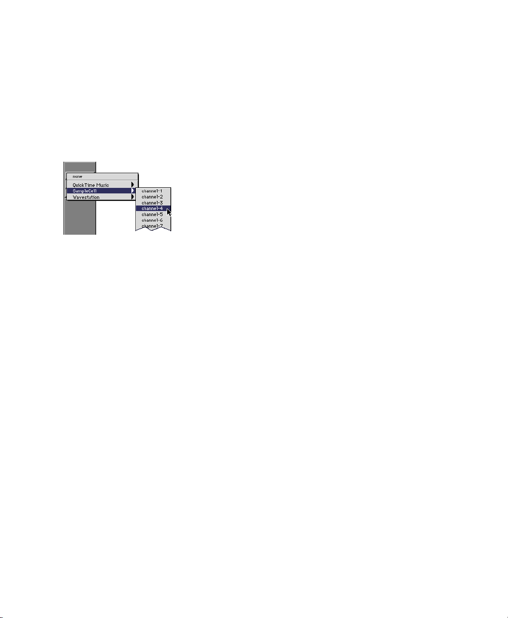
Recording MIDI
To configure a new MIDI track for recording:
1 Choose File > New Track and specify 1 MIDI
Track, then click Create.
2 In the Mix window, click on the track’s MIDI
Device/Channel Selector and assign a device
and channel from the pop-up menu.
MIDI Device Channel Selector
3 If you want, you can assign a default program
change to the track by clicking on the Program
button in the Mix window and making the necessary selections for program and bank select,
and then click Done. Default program changes
are sent when playing a track.
4 In the Mix Window, record-enable the MIDI
track.
5 Make sure MIDI > MIDI Thru is selected, then
play some notes on your MIDI controller. The
MIDI instrument assigned to the track should
sound, and the track’s meters should register
MIDI activity.
3 Click Record in the Transport window.
4 Click Play in the Transport window or press
the Spacebar to begin recording.
– or –
If using Wait for Note, the Play, Record, and
Wait for Note buttons flash. Recording begins
when the first MIDI event is received.
– or –
If using Countoff, click Play. The Record and
Play buttons flash during the Countoff—after
which, recording begins.
5 Play your MIDI instrument.
6 When you have finished recording, click Stop
in the Transport window, or press the Spacebar.
The newly recorded MIDI data appears as a MIDI
region on the track in the Edit window, as well
as in the MIDI Regions List.
To play back the recorded MIDI track:
1 Disable record-enable on the MIDI track to
take it out of Record-Ready mode.
2 In the Transport window, click Return To Zero.
3 Click Play in the Transport window to begin
playback. The recorded MIDI data plays back
through the track’s assigned instrument and
channel.
To record the new MIDI track:
1 Verify that the MIDI track you want to record
to is record-enabled and receiving MIDI.
2 In the Transport window, click Return To Zero
to ensure that recording starts from the beginning of the track. You can also record according
to a selection or from the cursor location in the
Edit window.
Chapter 5: Working with Pro Tools 59
Page 66

Monitoring MIDI Instruments Without a Mixer
Create an Auxiliary Input to monitor your MIDI
instrument. Auxiliary Inputs function as inputs
for both internally bussed signals and external
audio sources.
To configure an Auxiliary Input for MIDI
monitoring:
1 Connect the MIDI instrument’s audio output
to the appropriate inputs on your audio interface.
2 Choose File > New Track and specify 1 mono
or stereo Auxiliary Input track, then click Create.
3 Click the Input selector of the Auxiliary Input
channel and choose the input to which your
MIDI instrument is connected.
4 Click the Output selector of the Auxiliary In-
put channel and choose an output.
5 Adjust the level of the Auxiliary Input with its
volume fader.
Audio and MIDI editing are typically used to:
• Fix or replace mistakes.
• Re-arrange songs and projects.
• Clean up track timing and rhythm by aligning
hits to Grid values like bars and beats, time
code, or other timebases.
• Create final tracks using selections from multiple takes (also known as a comp track, or
compilation).
Edit Modes
Pro Tools has four Edit modes: Shuffle, Spot,
Slip, and Grid. The Edit mode is selected by
clicking the desired button in the upper left of
the Edit window.
Edit mode buttons
You can also use F1 (Shuffle), F2 (Slip), F3
(Spot), and F4 (Grid) to set the Edit mode.
Editing
Pro Tools provides many tools for editing audio
and MIDI tracks. Editing is done primarily in the
Edit window. The Edit window toolbar provides
Edit mode and Edit Tool selectors.
Edit Modes
Edit modes and tools (Grid mode, SmartTool enabled)
Getting Started with MIX60
Edit Tools
The Edit mode affects the movement and placement of audio and MIDI regions (and individual
MIDI notes), how commands like Copy and
Paste function, and also how the various edit
tools (Trimmer, Selector, Grabber, and Pencil)
work.
For detailed descriptions of Edit mode, see
the Pro Tools Reference Guide.
Edit Tools
Pro Tools has seven Edit tools: Zoomer, Trimmer, Selector, Grabber, Scrubber, Pencil, and
Smart Tool. Select the desired Edit tool by clicking it in the tool bar along the top of the Edit
Page 67

window. The Trimmer, Grabber, and Pencil tools
have multiple modes. Click and select the desired mode from a pop-up menu for these Edit
tools.
ginning of the region, and there is some extra
audio at the end of the region, you can use the
Trimmer tool in Slip mode to shorten the beginning and end of the region as desired.
Trimmer
Zoomer
Edit tools in Edit window
Selector
Smart Tool
Grabber
Scrubber
Pencil
Use the Esc key to toggle through the Edit
tools.
For detailed descriptions of the Edit Tools,
see the Pro Tools Reference Guide.
Editing Regions
Edit tools are used to edit regions in the Edit
window. A region is a piece of audio or MIDI
data that can also have associated automation
data. A region could be a loop, a guitar riff, a
verse of a song, a sound effect, a piece of dialog,
or an entire sound file. In Pro Tools, regions are
created from audio or MIDI files, and can be arranged in audio and MIDI track play-lists.
Audio region on a track
To trim an audio region:
1 Select Slip mode.
2 Select the Trimmer tool.
3 Move the cursor near the beginning of the au-
dio region (notice the cursor changes to a “[”).
Trimming the beginning of a region
4 Click at the beginning of the region and drag
right to shorten the region.
5 Move the cursor near the end of the audio re-
gion (notice the cursor changes to a “]”).
Audio region
Trimming Regions
The following example demonstrates how you
might trim a region to exclude unwanted audio.
After having recorded an audio track (for example, a guitar solo), you will have an audio region
on that track. If there is some silence at the be-
Trimming the end of a region
6 Click at the end of the region and drag left to
shorten the region.
The trimmed region
Chapter 5: Working with Pro Tools 61
Page 68
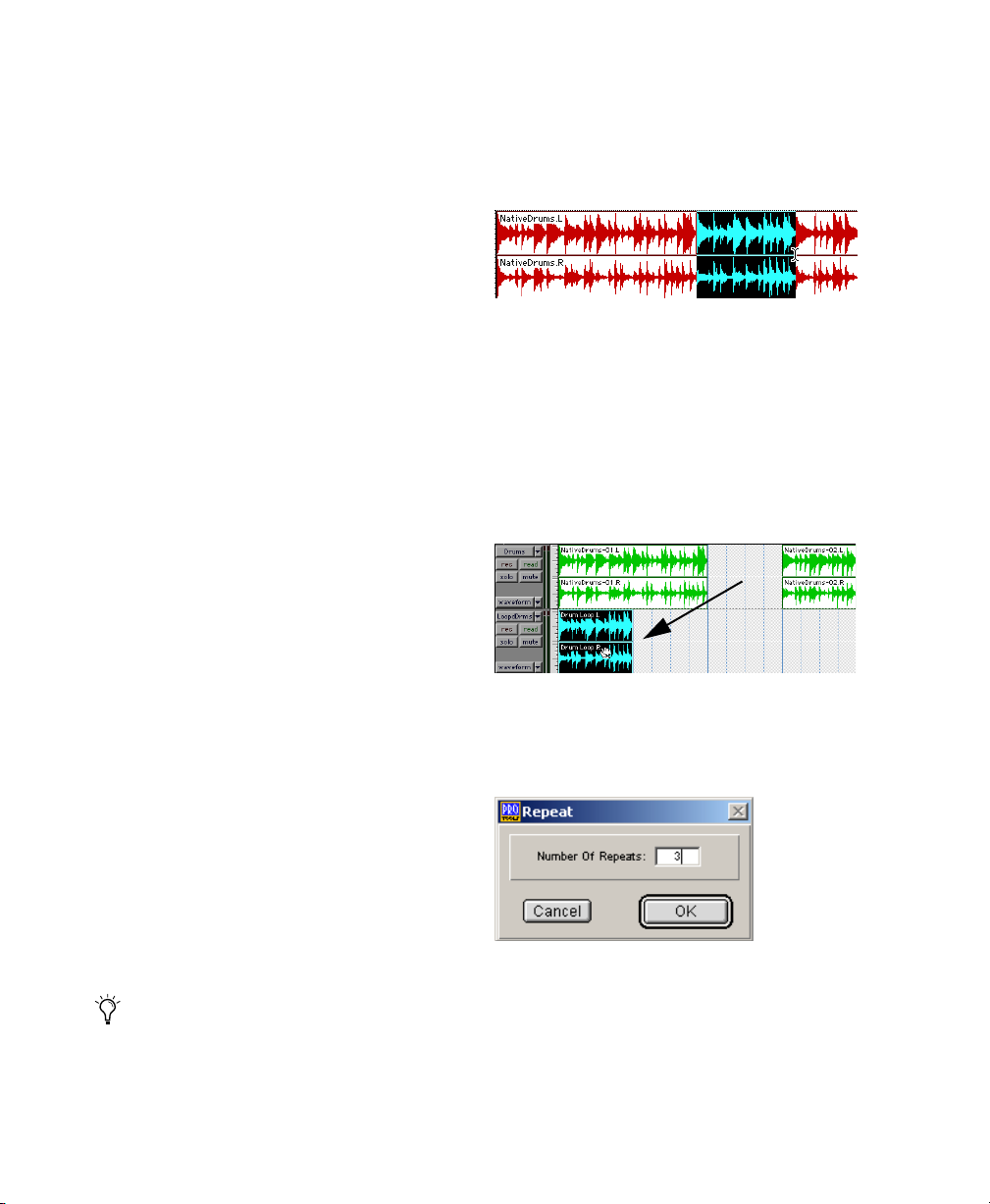
You can also lengthen a region using the trimmer tool if there is audio data beyond the current boundaries of a region. If trimming the region’s beginning, click and drag to the left; if
trimming the region’s end, click and drag to the
right.
Arranging Regions
5 Select the Selector tool.
6 Click and drag on the waveform with the Se-
lector to make the desired selection. Note that
the selection snaps to the grid.
There are many ways to edit and arrange regions; the following example demonstrates how
you might create and arrange a drum loop to
compose a rhythm track.
To create and arrange a rhythm sequence:
There are many ways to edit and arrange regions; the following example demonstrates how
you might create and arrange a drum loop to
compose a rhythm track.
To create and arrange a rhythm sequence:
1 Specify the session meter (MIDI > Change
Meter) and tempo (MIDI > Change Tempo).
2 Select Grid mode.
3 Prepare to record using a MIDI click (see
“Click and Metronome” on page 50)
4 Record a drum track (see “Recording an Audio
Track” on page 58) keeping in mind that you
want to use only the best bar (measure). Your recording should fit the grid at the specified
tempo and meter.
– or –
Making a selection in Grid mode
7 Create a new audio track (File > New Track).
8 From the Grabber pop-up, select the Separa-
tion Grabber tool.
9 With the Separation Grabber tool, click and
drag the selection to the beginning of the new
audio track. A new region will be created and appear at the beginning of the new track.
Dragging a selection with the Separation Grabber tool
to a track
10 With the new region still selected, choose
Edit > Repeat.
Import an existing audio file, such as a drum
loop from a sample library, and place it on an
audio track (see “Importing Audio” on page 56).
If you do not know the tempo of an audio region, you can use the Identify Beat command and then calculate the tempo from
the selection.
Getting Started with MIX62
Repeat dialog
11 In the Repeat dialog, enter the desired num-
ber of repeats, and then click OK.
Page 69
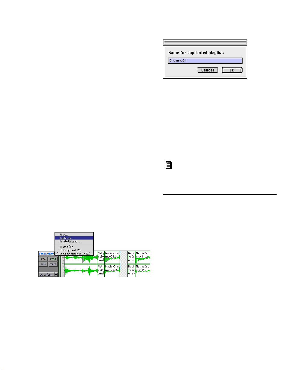
You now have a new rhythm track with a
“looped” (repeated) phrase. You can use these
editing tools to do much more advanced and involved editing of regions. For example, you
could separate beats or “hits” into individual regions and rearrange them in Grid mode as a way
of coming up with new and interesting
rhythms.
Playlists and Non-Destructive Editing
Playlists let you create and retrieve multiple versions of track edits. A playlist can be a complete
take, an overdub, or an arrangement of selections from multiple takes. You can duplicate
playlists to save edits in their current state, then
continue making additional edits to the new
playlist knowing you can always go back to the
previous version. The following example demonstrates how you can use playlists to create different versions of track edits.
To create multiple playlists for editing:
1 Start with a track on which you want to try
different edits.
2 From the Playlist Selector pop-up menu,
choose Duplicate.
Duplicating a playlist
3 Name the duplicated playlist and click OK.
4 Make your first series of edits as desired.
5 Return to the original playlist by selecting it
from the Playlist Selector pop-up menu.
6 Repeat steps 2–5 as desired.
In this fashion, you can try out different edits of
a track, and switch back and forth for comparison until you come up with the best version,
while maintaining the original playlist.
For detailed information about editing in
Pro Tools, see the Editing and MIDI Editing
chapters of the Pro Tools Reference Guide.
Mixing
Pro Tools provides many familiar channel strip
controls for setting track level, pan, solo, and
mute (see Figure 4 on page 54). You can also automate your mix or use a control surface to
“play” your mix in real-time. Once you have finished preparing your mix, you will probably
want to mixdown to a stereo recording. For example, you can record your mix to an external
analog or digital deck (such as a cassette or
DAT), or you can “bounce” your mix to a stereo
file so you can burn it to CD.
Mixer and I/O controls for signal routing can be
shown in both the Mix and Edit windows. Mixing is done primarily in the Mix window.
Chapter 5: Working with Pro Tools 63
Page 70

To view the Mix window:
■ Select Windows > Show Mix.
Use Command+”=” on Macintosh, or
Ctrl+”=” on Windows, to quickly switch
between the Edit and Mix windows.
Using Channel Strip Controls
Volume Increase or decrease the track level by
clicking the Volume fader and dragging it up or
down.
Pan Pan a track left or right in the mix by clicking the Pan slider and dragging it left or right.
Solo Solo a track (muting all other tracks) by
clicking the Solo button.
Creating a Send
Pro Tools provides up to five sends per audio
track. A send can be mono or stereo, routing to
an output or one of 64 internal bus paths (as
configured in Setups > I/O Setup).
When you are submixing for reverb, delay, and
similar effects processing, use sends to achieve
traditional send/return bussing. You can use a
real-time plug-in (see “Plug-Ins” on page 66) or
a hardware I/O insert (see “Connecting Effects
Units” on page 42) as a shared resource for all
tracks included in a submix. The wet/dry balance in the mix can be controlled using the
track faders (dry level) and Auxiliary Input fader
(effect return, or wet, level).
Mute Mute a track by clicking the Mute button.
Basic Signal Routing
Signal routing is accomplished by assigning
track inputs and outputs. Audio track inputs can
be from any hardware input. Once recorded, an
audio track’s input is its audio file on disk. Auxiliary Track inputs can be any hardware input or
internal mix bus. For all types of audio tracks,
outputs can be routed to any hardware output
or internal bus send.
Together, these signal routing features let you
set up virtually any mixer architecture needed
for your projects, including submixing, sends
and returns for effects processing, and multichannel mixing for surround.
To assign a send on a track:
1 Make sure Sends View is enabled in the Mix
window (Display > Mix Window Shows > I/O
View).
2 Click the Sends button on an audio track and
choose a path from the pop-up menu.
Assigning a send to a mono bus path
Getting Started with MIX64
Page 71
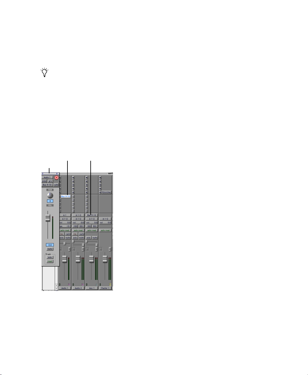
3 Set the output level of the send. You can set
the send level to zero by Option-clicking (Macintosh) or Alt-clicking (Windows) the send
fader. When you create a new send, its output
level is automatically set to –∞.
You can configure the default level for new
sends to be off or at unity gain (0) by enabling or disabling the Sends Default To
“–INF” option under the Operation tab in
Setups > Preferences.
Creating a Return
Auxiliary Input tracks can be created to act as return channels for busses, as well as for inputs
from hardware sources.
Send Aux Input
to bus 9–10 input from bus 9–10
Send window
To assign a return:
1 Choose File > New Track and specify 1 mono
or stereo Auxiliary Input track, then click Create.
2 Click the Input Selector of the Auxiliary Input
track and set it to the bus path you assigned to
the sends on the source tracks.
3 Click the Output Selector of the Auxiliary In-
put track and choose an output path (your main
mix, or other output).
Master Faders
Master Faders are provided, to be used as output
and bus masters. Master Faders can be used for
master level, solo, mute, and insert assignment
(plug-ins or hardware inserts) of any mono, stereo, or multichannel Output or Bus path. It is
recommended that you use a dithering plug-in
on a Master Fader when you are mastering your
final mix (see “Dithering” on page 68).
The available choices for inputs, outputs, and
busses are configured in the I/O Setup window.
For more information on the I/O Setup window,
see the Pro Tools Reference Guide.
Audio and Auxiliary Input tracks configured for a send
and return
To create a Master Fader:
1 Choose File > New Track and specify 1 mono,
stereo, or multichannel Master Fader track, then
click Create.
2 In the Mix window, click the Master Fader’s
Output Selector and choose the output path
that you want to control. You can choose either
audio interface outputs or internal busses. If the
Master Fader is a stereo fader, you can control
the level of a pair of outputs.
Chapter 5: Working with Pro Tools 65
Page 72
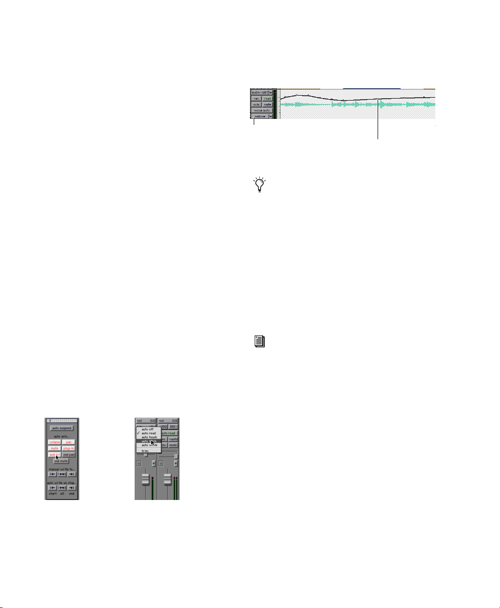
To use Master Faders as a master volume control
for all tracks in a session:
1 Choose File > New Track and specify 1 stereo
Master Fader track, then click Create.
2 Set the outputs of all audio tracks in the ses-
sion to outputs 1–2 and set the panning of each
track.
3 Set the output of the Master Fader to your
main output path (outputs 1–2).
Once recorded, automation can be re-recorded,
or displayed and edited graphically in the Edit
window.
Track View set to Volume
Volume breakpoint automation
Volume automation in a track in the Edit window
Mix Automation
Mix automation lets you record, or automate,
changes to track and send levels, mutes, pan,
and plug-in parameters. MIDI tracks provide
track level, pan, and mute automation only.
The basic steps for automation recording are:
1 In the Automation Enable window, enable an
automation type (volume, pan, mute, send level,
send pan, send mute, or any plug-in automation).
2 Select an automation mode for the tracks to be
automated (Write, Touch, Latch, or Trim mode).
3 Begin playback and begin automation record-
ing, adjusting faders and other controls as desired. Pro Tools remembers all moves performed
on enabled parameters.
Pro Tools also provides Automation Safe
mode for protecting plug–in automation
from being overwritten, as well as many Automation Preferences to fine-tune performance. See the
Pro Tools Reference Guide.
Mixing with a Control Surface
Rather than mixing with a mouse—adjusting
one fader at a time—you might find using a
MIDI or ethernet control surface (such as
Pro Control) for mixing to be much more effective.
For more information on using Pro Control,
see the Pro Control
Guide.
For more information on using MIDI control surfaces, see the MIDI Control Surface
Guide.
Plug-Ins
Pro Tools comes with a complete set of DigiRack
plug-ins, and many more are available from
Digidesign and our Development Partners. Plugins provide EQ, dynamics, delays and many
other types of effects processing.
Enabling automation (left) and setting a track
Automation mode (right)
Getting Started with MIX66
Plug-ins function either in real-time or in nonreal-time. TDM and RTAS plug-ins are non-destructive effects, which are inserted on tracks to
process audio in real-time—just like an external,
Page 73
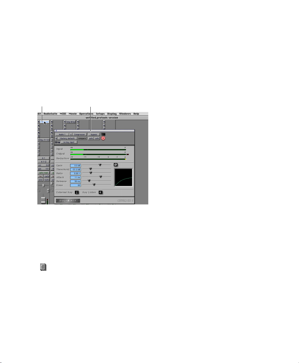
hardware processor (during playback). AudioSuite plug-ins, on the other hand, are destructive effects that process audio files on disk in
non-real-time.
Real-time plug-ins are assigned to tracks from
the Inserts view in the Mix or Edit windows.
Once assigned to a track, plug-ins appear in the
track’s Inserts view, and can be opened by clicking on the Insert button.
Plug-InInsert button
Compressor plug-in
To insert a real-time plug-in on a track:
1 Make sure the Inserts View is shown in the
Mix or Edit window.
2 Click the Insert Selector on the track and se-
lect the plug-in that you want to use.
Bounce to Disk
The Bounce to Disk command lets you write a final mix to disk, create a new loop, print effects,
or bounce any submix. Once you have
“bounced” your final mix to disk, you can use
another program (such as MasterList CD) to
burn the resulting file to Compact Disc.
When you bounce a track to disk, the bounced
mix includes the following:
Audible Tracks All audible tracks are included in
the bounce. Any muted tracks do not appear in
the bounce. If you solo a track or region, only
the soloed elements appear in the bounced mix.
Automation All read-enabled automation is
played back and incorporated in the bounced
mix.
Inserts and Sends All active inserts, including
real-time plug-ins and hardware inserts, are applied to the bounced mix.
Selection or Track Length If you make a selection in a track, the bounced mix will be the
length of the selection. If there is no selection in
any track, the bounce will be the length of the
longest audible track in the session.
Time Stamp Information Bounced material is automatically time stamped so that you can drag it
into a track and place it at the same location as
the original material.
For more information about plug-ins, see
the DigiRack Plug-Ins Guide, the Digidesign Plug-Ins Guide, and the Plug-Ins chapter of the Pro Tools Reference Guide.
To Bounce to Disk:
1 Choose File > Bounce to Disk.
2 Select any mono, stereo, or multichannel out-
put or bus path as the source for the bounce.
3 Select the File Type (such as AIFF), Format
(such as mono or stereo), Resolution (such as 16bit), and Sample Rate (such as 44.1 kHz).
4 Click Bounce.
Chapter 5: Working with Pro Tools 67
Page 74

Dithering
You should use a dithering plug-in when mastering to a 16-bit file with the Bounce To Disk
command, or when mastering to an external device that records at 16-bit. If you use Bounce to
Disk, it is important to understand that the
Bounce to Disk process does not apply dither. To
dither a bounce file, you should insert one of
the included Digidesign Dither plug-ins, or another dithering plug-in, on a Master Fader assigned to the bounce source path. Master Faders
are often preferable to Auxiliary Inputs because
Master Fader inserts are post-fader (better for
dithering).
For more information on using dither, see
the
Pro Tools Reference Guide.
Getting Started with MIX68
Page 75

appendix a
Connecting SCSI Drives
SCSI hard drives function as the recommended
recording media for Pro Tools TDM systems; it is
there that Pro Tools sessions and audio files are
kept.
Although Pro Tools will let you record to your
system drive, this is generally not recommended. Performance for recording and playback on system drives is worse than on non-system drives, resulting in lower track counts and
fewer plug-ins.
SCSI Requirements
High-Performance SCSI Drives and SCSI Host Bus Adapters
For 64-track, 24-bit, at 44.1 or 48 kHz performance, a TDM system must include at least
three Digidesign-qualified SCSI hard drives attached to a qualified SCSI HBA (host bus
adapter) card.
SCSI hard drives offer several advantages over
ATA/IDE drives. First, SCSI drives can be external and therefore provide portable audio storage
that is easily moved between systems. Second,
SCSI drives offer better performance when recording to large numbers of tracks; attempting
to record to a large number of audio tracks with
an ATA/IDE drive results in a short delay before
recording begins.
For 64-track sessions that have substantial edit
densities (such as one edit every third of a second across 64 voices) or large amounts of crossfades, up to four SCSI drives may be required, allocated with 24 tracks per drive and two drives
per SCSI channel.
SCSI drives must provide a data transfer rate of
at least 9 MB per second of sustained throughput.
Refer to the Digidesign Web site for compatible
hard drives and HBA cards:
www.digidesign.com/compato/
Software RAID is not supported for audio
drives.
Appendix A: Connecting SCSI Drives 69
Page 76

SCSI Cables
Disk Space for Audio Tracks
Use shorter SCSI cables to improve reliability.
Table 1 provides guidelines for maximum cable
lengths according to SCSI type.
In the following table, the maximum cable
length includes all cables used in the chain, not
just point-to-point connections.
Table 1: Maximum cable length and number of drives
supported according to SCSI type
SCSI type and
transfer rate
Fast SCSI
10 MB/sec
Wide SCSI
20 MB/sec
Ultra SCSI
20 MB/sec
(8-bit narrow)
Ultra SCSI
40 MB/sec
(16-bit wide)
Ultra SCSI
20 MB/sec
(8-bit narrow)
Ultra SCSI
40 MB/sec
(16-bit wide)
Ultra2 SCSI
Low Voltage Differential (LVD)
80 MB/sec
maximum
cable length
3 meters 8
3 meters 16
3 meters 5
3 meters 5
1.5 meters 6–8
1.5 meters 6–8
1.2 meters 16
maximum #
of drives
A single mono audio track recorded at 24-bit resolution at a CD-fidelity sampling rate of
44.1 kHz requires about 7.5 MB of hard drive
space per minute. The same track recorded at
16-bit resolution requires about 5 MB per
minute. Stereo tracks require about twice as
much hard drive space.
Using these guidelines:
• 64 mono tracks of 44.1/48 kHz, 24-bit audio
takes up about 500 MB of hard drive space per
minute.
• 64 mono tracks of 44.1/48 kHz, 16-bit audio
takes up about 350 MB of hard drive space per
minute.
Distribute Audio Across Multiple Drives
For best recording and playback performance,
don’t record and play back all audio files in a
session from the same drive. Instead, use
Pro Tools Disk Allocation features to distribute
audio files between multiple drives. See the
Pro Tools Reference Guide for details.
Separate Video and Audio Files
If you are working with QuickTime, movie files
must reside on a different SCSI bus than audio
files. If audio files reside on disks connected to a
SCSI HBA card, video data should reside on
drives connected to a different SCSI bus.
Dual-Channel SCSI HBA Cards
If you use a dual-channel SCSI HBA card, equally
allocate audio files to drives connected to each
of the two busses on the card for optimal performance.
If using video files, make sure to put your video
files on one bus and audio files on the other bus.
Getting Started with MIX70
Page 77

Connecting SCSI Drives
To connect an external SCSI drive:
1 Turn off power to both the computer and the
hard drive.
2 Attach a SCSI cable from the SCSI port of the
hard drive to the SCSI port of the SCSI HBA card
or computer depending on your system’s SCSI
requirements.
3 Secure the cable’s connectors to the hard drive
and computer. Loose cables can cause data loss.
4 Connect additional drives by daisy-chaining
from one drive to another. Keep cable lengths to
a minimum (see Table 1).
5 Verify that the last SCSI device connected is
properly terminated. (See “SCSI Termination”
on page 71.)
6 Attach power cables to the hard drives.
to SCSI accelerator card
Connecting an external SCSI hard drive
SCSI Termination
Your computer’s SCSI chain must be properly
terminated or your system will not function correctly. Only the last device on the chain should
be terminated using the termination type recommended by the hard drive manufacturer.
The drive should use either an external terminator plug or have its internal terminators enabled. If you are using a terminator plug, Digidesign recommends that you purchase and use an
active terminator.
Do not enable internal termination and install an external terminator plug on the
same drive. This will cause SCSI errors. See
your hard drive’s documentation for information regarding which type of termination
it uses.
SCSI accelerator card
to SCSI hard drive
Connecting a SCSI cable to a SCSI HBA card
Quick Formatting a SCSI Drives
Macintosh Requirements
On Macintosh systems, SCSI hard drives used
for audio recording on TDM systems must be
formatted (or initialized) for either the HFS or
HFS+ file system. Drive partitions of up to
2 terabytes (2000 gigabytes) can be used.
Appendix A: Connecting SCSI Drives 71
Page 78

TDM systems require that you use the ExpressPro-Tools software from ATTO (included
with Pro Tools) for all drive formatting and partitioning; only one disk utility should be used
for all drives in a system.
Windows Requirements
SCSI hard drives used for audio recording on
TDM systems must be formatted for the FAT32,
or NTFS files system. Under Windows 2000,
NTFS drive partition sizes are only bound by the
physical size of the drive, whereas FAT32 drive
partitions have a limit of 32 GB.
The following restrictions apply:
• The drive letter cannot be A: or B:.
• It must be a normal fixed hard drive (the function GetDriveType must return
DRIVE_FIXED).
• The file system must be FAT32, NTFS, or HFS
(w/ MacOpener installed).
• The user must be logged in as administrator
• The drive must have valid signature.
• DAE is not compatible with Windows 2000
dynamic disks. Only basic disks work with
Pro Tools on Windows 2000. Note that the
Windows 2000 Disk Administrator in some
cases makes new disks dynamic by default.
Use the revert to basic disk option to change
this.
• Stripe sets are currently not supported.
TDM Windows systems require that you use Microsoft Windows Disk Administration software
for drive formatting and partitioning. Use only
one disk utility for all drives in a system.
Pro Tools for Windows 2000 allows you to
connect Macintosh-formatted hard drives
and play sessions created on Pro Tools for
Macintosh when using MacOpener from
DataViz. An installer for the demo version
of MacOpener is included as an installation
option for Pro Tools.
Initializing a Macintosh Drive
To initialize a new drive:
1 Turn on your hard drives, computer, and any
other peripherals.
2 Use ATTO’s ExpressPro-Tools software version
2.3.2 to initialize and partition any new hard
drives.
Refer to the
ExpressPro-Tools User’s Manual.
If you have existing FWB-formatted drives,
don’t install the ExpressPro-Tools extension; this can cause a conflict. This extension is not required to use the ExpressProTools software (to format new drives).
Formatting a Windows Drive
To format a new drive:
1 Turn on your hard drives, computer, and any
other peripherals.
2 Use Microsoft’s Disk Management software,
located in the Administrative Tools control
panel under Computer Management > Storage.
Refer to your Microsoft Windows manual or
Windows help for information on how to use
the Disk Management software.
Getting Started with MIX72
Page 79

General Hard Drive Maintenance Information
If using Macintosh drives on Windows systems, refer to“Using Macintosh Drives on
Windows Systems” on page 75.
Formatting Drives
There are two different types of formatting:
high-level formatting and low-level formatting.
Digidesign does not recommend low-level
formatting.
High-Level Formatting (Initialization)
High-level formatting, or initializing a drive replaces the drive’s directory, volume partition
map and drivers. Information about the drive is
created and drivers that communicate this information to the host CPU are installed. The
drive itself is not erased, nor is verification performed.
When is High-Level Formatting Necessary?
Low-Level (Physical) Formatting
Low-level formatting means completely erasing
the hard drive and rewriting each sector address
on the drive. In low-level formatting, the sector
and track addresses, error-correction codes, and
other details are written on the platters of the
hard drive in the form of a magnetic pattern. A
low-level format permanently erases all data on
the drive.
When is Low-Level Formatting Necessary?
Virtually all hard drives come pre-formatted
from the manufacturer. Low-level formatting is
generally unnecessary except in rare circumstances. They are:
◆ If you want to change the Block Size of the
drive. This is not recommended by Digidesign.
Digidesign systems only recognize 512-byte
blocks.
◆ If you want to perform permanent deletion of
data.
◆ If you want to clean a drive that is being mi-
grated from one operating system to another
(for instance, from UNIX to Macintosh).
It is generally necessary to high-level format a
hard drive in one of the following cases:
◆ If a new drive is being prepared for use on a
computer for the first time and the drive is not
already high-level formatted.
◆ If you suspect that the directories containing
the drive’s information have become corrupted.
◆ If a drive is being changed from one platform
to another. For example if you are switching
from a Macintosh to a Windows-based system,
or from a Windows to a Macintosh-based system, the drive must be high-level re-formatted
for the new operating system.
Should you decide low-level formatting is necessary, keep in mind that it can take up to three
hours or more (depending on the size of the
drive). Avoid power interruptions and computer
bus resets during the format operation or permanent damage to the drive could occur. In addition, leave the drive powered on for at least 30
minutes prior to formatting so that the drive has
time to make any necessary thermal adjustments or recalibrations.
Appendix A: Connecting SCSI Drives 73
Page 80

Partitioning Drives
Avoiding File Fragmentation
Partitioning divides a physical drive into multiple, unique volumes, almost as if you were creating virtual hard drives. Partitioning is usually
performed when the drive is high-level formatted (Macintosh) or initialized (Windows).
Mac OS 7.6.1 and above allows drives
larger than 4096 MB to be seen as whole
volumes. Drives must be initialized with
ExpressPro-Tools (or another utility) that
recognizes the 2 terabyte limit. Single files
cannot exceed 2048 MB in size.
Windows 2000 allows drives formatted
with the NTFS or FAT32 file systems to be
seen as whole volumes. Single Pro Tools audio files cannot exceed 2048 MB in size.
Seek Times on Partitioned Drives
Seek times are actually faster on partitioned
drives (assuming that reads and writes are performed on a single partition), since the heads
only have to seek within the partition boundaries, rather than the whole capacity of the
drive.
In addition, smaller partitions perform faster
than larger partitions. However, this comes at
the expense of contiguous storage space. When
you partition a drive, you will need to find the
compromise that best suits your performance
and storage requirements.
Avoid distributing audio files within a session over different partitions on the same
drive since this will adversely affect drive
performance.
For maximum recording and playback efficiency, data should be written to your hard
drive in a contiguous fashion—minimizing the
seek requirements to play back the data. Unfortunately, your computer can’t always store the
sound files in this way and must write to disk
wherever it can find space.
In multitrack recording, audio tracks are written
in discrete files, spaced evenly across the disk.
While fragmentation of individual files may be
zero, the tracks may be far enough apart that
playback will still be very seek-intensive. Also,
the remaining free space on the disk will be discontiguous, increasing the likelihood of file
fragmentation on subsequent record passes.
Increased fragmentation increases the chance of
disk errors, which can interfere with playback of
audio, and result in performance errors.
On Windows, fragmentation is less likely to
occur on drives formatted with higher cluster sizes (such as 32k, which is strongly recommended for optimal performance with
Pro Tools). On Windows 2000, use Windows Disk Administrator to format FAT32,
and use Partition Magic to format NTFS.
On Macintosh, if Norton Utilities is used, it
must be Norton Utilities v4.0 or later to ensure compatibility with HFS+ drives.
Optimizing (Defragmenting) Drives
To prevent fragmentation, you can optimize
your drive, which rearranges your files into a
contiguous format. Most optimizing software
lets you run a check on a drive to find out the
percentage of fragmentation. If your drive
shows moderate to heavy fragmentation, you
should consider optimizing it.
Getting Started with MIX74
Page 81

If you use your system for intensive editing, or if
you frequently delete audio or fade files from
your hard drive, you may need to optimize your
drives on a weekly basis, or even every few days,
since it doesn’t take long for even a large hard
drive to become fragmented.
On Windows 2000, it is not possible to defragment NTFS formatted drives that have
a cluster size larger than or equal to 4k.
This is not an issue with FAT32 formatted
hard drives.
Backing Up Data Before Optimizing
Installing the MacOpener Utility
To Install MacOpener:
1 Quit Pro Tools if it is open.
2 Locate the macopener executable (.exe) file on
the Pro Tools Installer CD-ROM and doubleclick it to launch the installer.
3 Follow the on-screen instructions to install
MacOpener.
4 When installation is complete, restart your
computer.
Since your files will be rewritten by the optimization process, always make a backup copy of
the data on your hard drive before you optimize
it. You should also use a hard drive utility to
find and repair any problems before optimizing
data. If there is any damage to your hard drive's
directories prior to optimizing, serious data loss
may result.
Using Macintosh Drives on Windows Systems
Pro Tools for Windows lets you record and play
back sessions directly from a Macintosh-formatted (HFS or HFS+) drive connected to a Windows
system. This functionality requires that all Macintosh session and audio files be stored on Macintosh-formatted drives.
To mount HFS or HFS+ drives on a Windows system, you must use the MacOpener
utility by DataViz. An installer for the demo version of MacOpener is included as an installation
option for Pro Tools.
™
software
Enabling the MacOpener Driver
When you are finished installing MacOpener,
the MacOpener driver must be enabled to
mount HFS and HFS+ drives.
To enable the settings on the MacOpener Driver:
1 Choose Start > Programs > MacOpener >
MacOpener Driver Preferences.
2 Under Driver Settings, select Enable Mac-
Opener Driver.
3 Under Extension Mapping, select Do not add
the PC extension to the Mac file name.
Mounting HFS Drives
If the MacOpener utility is installed and enabled, no additional steps are required to mount
HFS drives. They appear as normal system drives
after you connect them and restart your computer.
For details on sharing sessions between
Macintosh and Windows systems, see the
Pro Tools Reference Guide.
Appendix A: Connecting SCSI Drives 75
Page 82

Formatting and Maintaining HFS and HFS+ Drives
Although you can use MacOpener to format HFS
and HFS+ drives from a Windows machine, it is
not recommended for use with Pro Tools. We
recommend that you connect the drives to a
Macintosh computer (if possible) and use the
ExpressPro-Tools software from ATTO (included
on the Mac Pro Tools CD-ROM).
Getting Started with MIX76
Page 83
appendix b
DigiTest Error Codes
DigiTest Error Codes
Code Description
Err3 Cards from different Pro Tools
systems are incorrectly mixed.
Err4 Cards marked with this error are
installed in the wrong order.
Err5 Too many cards of this type are
installed in the system. Refer to
the Digidesign Web site for compatibility information:
www.digidesign.com/compato/
Err6 A card is installed in a reserve
slot. For example, a Digidesign
card is installed in the slot
reserved for the Expansion Chassis Host Interface card.
Err1010 Too many MIX Core cards
installed. The maximum number
of MIX Core cards allowed is 7.
Err1011 Too many MIX Farm cards
installed. The maximum number
of MIX Farm cards allowed is 7.
Err1012 Too many total MIX cards
installed. The maximum number
of total MIX cards allowed is 7.
DigiTest Error Codes
Code Description
Err1022 Too many total d24 cards
installed. The maximum number
of total d24 cards allowed is 2.
Err1220 SCSI Accelerator card is installed
in the wrong slot.
Err1221 Expansion Chassis Host Interface
card is installed in the wrong slot.
Err1301 A Core card is not installed. At
least one Cord card is needed.
Err1310 A DSP Farm card is not installed.
At least one DSP Farm card is
needed.
Err1020 Too many d24 Core cards
installed. The maximum number
of d24 Core cards allowed is 2.
Err1021 Too many MIX I/O cards installed.
The maximum number of MIX I/O
cards allowed is 2.
Appendix B: DigiTest Error Codes 77
Page 84

Getting Started with MIX78
Page 85
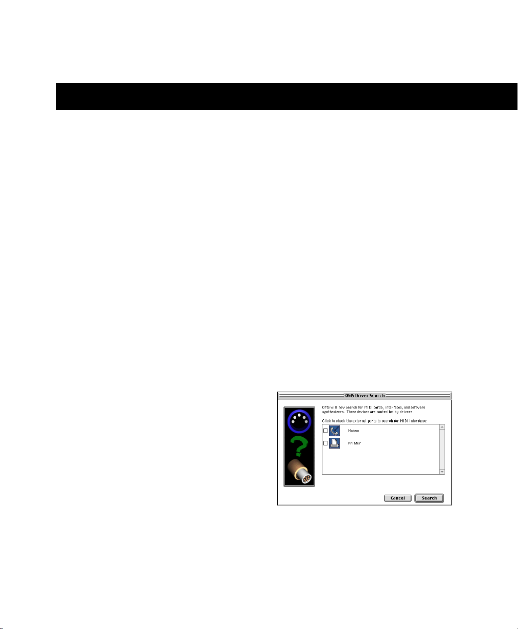
appendix c
Configuring OMS (Macintosh Only)
Open Music System (OMS), which is included
on the Pro Tools Installer CD, has the following
capabilities:
• Keeps track of which MIDI devices you are using, how they are connected, and which
patches they are using
• Enables MIDI hardware to communicate with
your music applications
• Provides timing services and inter-application
communication
OMS stores a description of your MIDI studio in
Studio Setup documents, which are edited in the
OMS Setup application. Once OMS is configured,
your music applications know which MIDI devices you are using by referencing the current
Studio Setup document.
The following sections provide basic instructions for configuring OMS. For more detailed information, refer to the online OMS Guide installed with Pro Tools.
Configuring a New Studio Setup
(First-Time OMS Users Only)
Before configuring OMS, make sure your MIDI
interfaces and devices are connected according
to the manufacture’s instructions and turned
on.
To configure a New Studio Setup in OMS:
1 Launch the OMS Setup application. If OMS
has not yet been configured, you’ll be prompted
to configure a New Studio Setup. Click OK.
2 Select whether your MIDI interface is con-
nected to the Modem or Printer port. If using a
USB or PCI-based MIDI interface, leave both
ports unchecked. Click Search.
Ports for OMS Driver Search
Appendix C: Configuring OMS (Macintosh Only) 79
Page 86
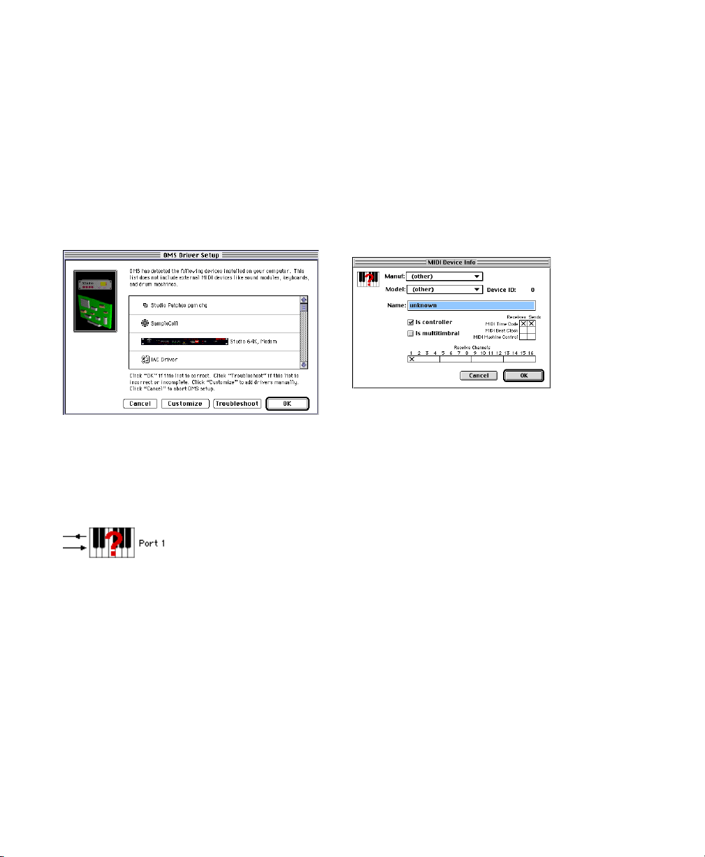
OMS searches for and displays any detected
MIDI interfaces, MIDI cards, and OMS drivers. If
your interface is not detected, click Troubleshoot. Once your interface is detected, you are
prompted to search for MIDI instruments connected to your interface.
3 Click OK to search for MIDI devices connected
to your MIDI interface. To be detected, the device must be turned on and have both of its
MIDI ports connected to your MIDI interface.
Defining MIDI Devices in OMS
To define a MIDI device in OMS Setup:
1 Double-click the device’s icon in the Studio
Setup window.
2 In the MIDI Device Info dialog, select the
Manufacture and Model for the device from the
pop-up menus. If the device is not listed, leave
the Model set to “other” and enter a name for
the device.
Defining a MIDI device
OMS Driver Setup
OMS searches for and displays any detected
MIDI devices. Some older instruments, as well as
some newer ones, may not be recognized by the
OMS auto-detection routines.
Undefined OMS device
Devices not recognized by OMS appear with a
red question mark and are named based on the
interface or port to which they are connected.
These devices can be defined as necessary within
the OMS Setup application (see “Defining MIDI
Devices in OMS” on page 80).
4 Click OK to save your Studio Setup document.
Getting Started with MIX80
3 Select the receiving channel for the device. If
receiving multiple channels, select the option
for “Is Multitimbral.”
4 If you will record from the device in Pro Tools,
select the option for “Is Controller.” If the device will be a source or destination for MIDI
Time Code, Beat Clock, or MMC, select the appropriate option.
5 Click Ok.
Page 87
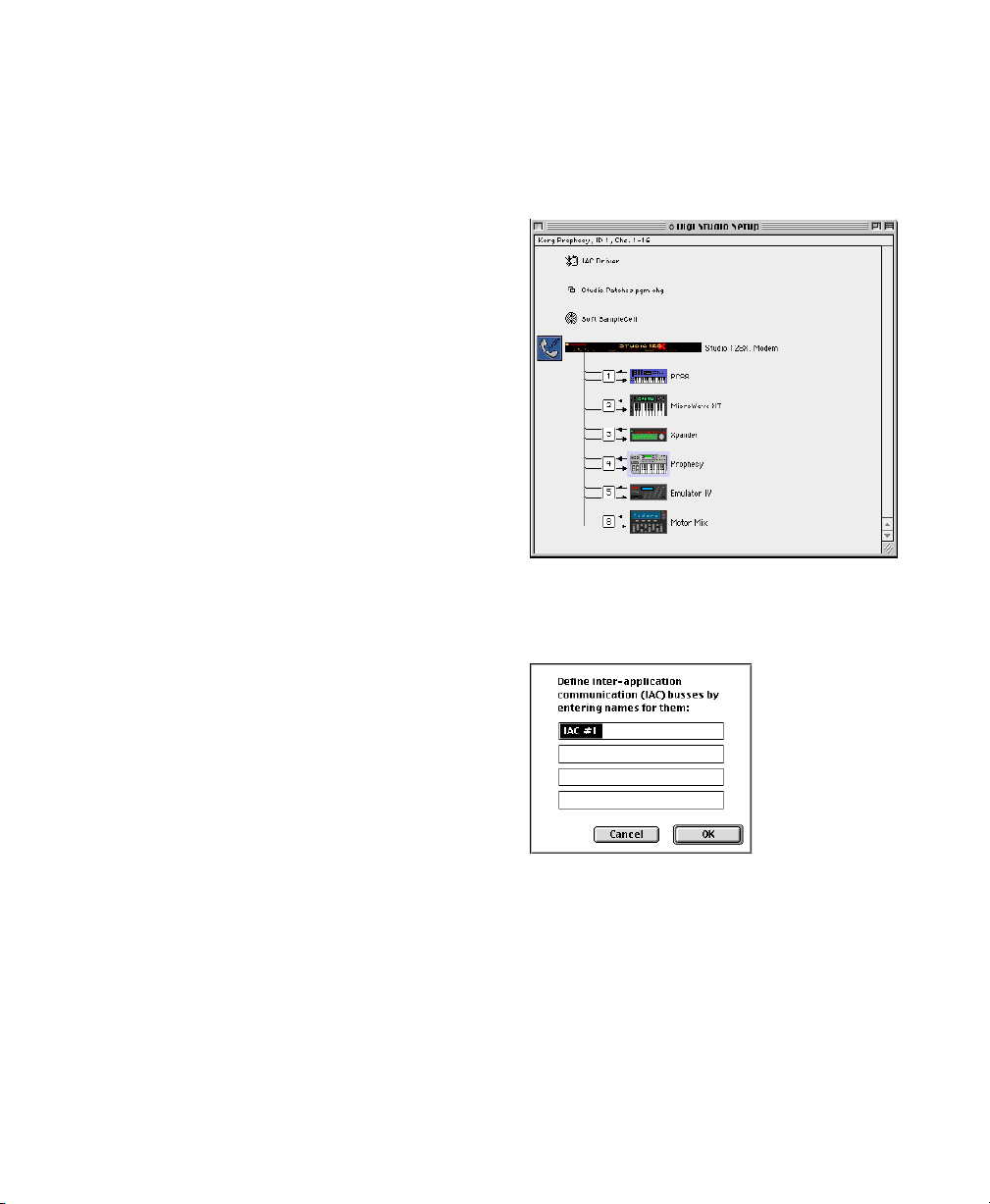
Disabling SerialDMA in OMS
Pro Tools requires that you deselect the “Use
Apple SerialDMA Driver When Available” option in OMS Setup. If you do not disable this option, problems will occur with MIDI and synchronization functions in Pro Tools.
To disable SerialDMA in OMS:
1 Double-click the OMS Setup application.
2 Choose Edit > Preferences.
3 Deselect “Use Apple SerialDMA Driver When
Available,” and click OK.
4 Quit OMS Setup
Machine Control and the IAC Driver
To edit the IAC driver’s name:
1 Double-click the OMS Setup application.
2 In the Studio Setup window, double-click the
IAC driver.
If you are planning to use MIDI Machine Control (MMC) for Pro Tools synchronization with
other MMC-capable devices or applications, you
must rename the OMS IAC Driver and remove
the infinity symbol (“∞”) from its name. If you
do not do this, MMC will not function properly.
Studio Setup window with IAC Driver
3 Rename “∞ IAC bus #1” to “MMC” and click
OK.
Renaming the IAC Driver
4 Quit OMS Setup.
Appendix C: Configuring OMS (Macintosh Only) 81
Page 88

Getting Started with MIX82
Page 89

appendix d
Digidesign Control Panel (Macintosh Only)
The Digidesign Control Panel should be installed if you are planning to use your Digidesign hardware with Apple Sound Manager-compatible applications.
Digidesign Control Panel
To configure the Digidesign Control Panel:
1 From the Apple menu, choose Control Panels
> Digidesign.
Digidesign Control Panel
2 Click the Setup Hardware button in the
Digidesign Control Panel. The Hardware Setup
dialog will open.
3 Configure the Hardware Setup dialog as de-
sired. The Other Options dialog will vary according to your primary audio interface.
To use your Digidesign hardware with Apple Sound
Manager:
1 Choose Apple menu > Control Panels >
Sound.
2 Select the Output tab.
3 Select Digidesign.
Apple Sound Control Panel
It is recommend that you turn the Alert Volume control all the way down under the
Alerts tab.
Appendix D: Digidesign Control Panel (Macintosh Only) 83
Page 90

Getting Started with MIX84
Page 91

appendix e
Digidesign WaveDriver (Windows Only)
effect on recording or playback in Pro Tools or
Introduction
The Digidesign WaveDriver is a two-channel,
multimedia sound driver for Digidesign's TDM
systems. This WaveDriver allows third-party audio applications to record and/or play through
channels 1–2 of the first peripheral connected to
your d24 or Mix Core card. It is compatible with
Windows 2000 (Service Pack 1 and Service
Pack 2).
Check the Digidesign Web site
(www.digidesign.com) for the latest thirdparty drivers for Pro Tools hardware, as
well as current known issues.
Recording and playback of 16-bit audio are supported at sample rates of 48 kHz and 44.1 kHz.
Other word lengths and sample rates are available through the Microsoft Sound Mapper.
Also included is the DigiGain volume control
application. DigiGain allows control over the
WaveDriver's master output volume, and input
and record monitoring levels. DigiGain has no
any other application that communicates with
Digidesign hardware using Digidesign
Direct I/O.
WaveDriver is not multi-client. Only one
application at a time can use the
WaveDriver. Be sure to disable the Windows system sounds. It is also recommended that you install a separate sound
card for third-party soft-synthesizer and
samplers, games, or multi-client audio
work.
Installing the WaveDriver
Before installing the driver please make sure of
the following:
Pro Tools hardware and software must be properly installed and functional prior to installing the
Digidesign WaveDriver
The WaveDriver shares several files with
Pro Tools. These shared files are installed with
Pro Tools, not the WaveDriver. After installing
Pro Tools, restart Windows. Your audio interface
must be connected and turned on to successfully install the Digidesign WaveDriver.
Appendix E: Digidesign WaveDriver (Windows Only) 85
Page 92

Disable System sounds before installing the
WaveDriver
Remove previously installed Digidesign
WaveDrivers
Digidesign recommends disabling all system
sounds. Users may encounter problems when
system sounds are associated with Empty Recycle Bin, Select, Open Program, and Close Program and other Windows events. In addition,
disabling the Windows Start and Exit Windows
sounds helps prevent possible speaker damage.
The Digidesign WaveDrivers default to 0 dB
when installed. Remember to turn down your
monitoring levels before reboot after the
WaveDrivers are installed.
With the WaveDrivers set for 0dB, your audio interface will output the system sounds
at >110dB!
To disable system sounds:
1 From the Start menu, choose Settings > Con-
trol Panel > Sounds.
2 To disable all system sounds, under the
Scheme pull-down menu select No Sounds.
– or –
To disable specific system sounds, scroll down
the list of Events and select the one you want to
disable such as Start Windows. In the Name
drop down list, select None.
3 Click Apply, then OK.
4 Restart Windows.
You should also disable Internet Explorer’s
sounds for the same reasons.
If you have previously installed an earlier version of the WaveDriver, you must completely
remove it before installing this new driver. For
more information, see “Removing the
WaveDriver” on page 87.
Installation Instructions
To install the Digidesign WaveDriver:
1 Install Pro Tools.
2 Launch any Pro Tools session to verify that
Pro Tools is working correctly.
3 Quit Pro Tools and restart your computer.
4 From the Start menu, choose Settings > Con-
trol Panel.
5 Click on Add/Remove Hardware.
6 Click on Next.
7 Select “Add/Troubleshoot a device.” Wait
while Windows searches for devices.
8 Select “Add a new device” and click on Next.
9 Select “No, I want to select the hardware from
a list” and click Next.
10 Select “Sound, video and game controllers”
and click Next.
11 Click “Have Disk...”
12 Browse to the location of the driver, select
the “oemsetup.inf” file, and click “Ok.”
13 Click Next.
14 If “Digital Signature” warning dialog ap-
pears, click Yes.
15 Click Next.
Getting Started with MIX86
Page 93

16 If message appears which states “The file ‘di-
rectio.dll’ on Digidesign WaveDriver is needed.”
Browse to the location of the driver, select the
“directio.dll” file, and click OK.
The Digidesign WaveDriver Settings dialog will
automatically open.
17 Click on the Advanced button to open the
I/O Setup dialog. (See How to Change
WaveDriver Settings below for more information about these dialogs.)
18 Click on the A: No Interface tab.
19 Select the Peripheral Type for the peripheral
you have connected to your d24 or Mix card.
The WaveDriver may only be used with the
first peripheral connected to your master/core card. If your d24 or Mix Core card is
connected to two peripherals using an optional
Digidesign 16-channel peripheral ca-
ble adapter
, select the Peripheral Type for
the peripheral connected to “A.” If you have
multiple Pro Tools cards connected to multiple peripherals, select the Peripheral type
for the “A” peripheral connected to your
d24 or MIX Core card. Use the Identify
checkbox in the I/O Setup dialog to verify
which peripheral you are configuring for use
with the WaveDriver.
20 Make any other desired settings in the I/O
Setup dialog.
21 Click OK to close the I/O Setup dialog.
22 Click OK to close the WaveDriver Settings di-
alog.
23 Restart Windows when prompted.
Removing the WaveDriver
To remove the WaveDriver:
1 From the Start menu, choose Settings > Con-
trol Panel.
2 Click the “Add/Remove Hardware” Icon.
3 Click Next.
4 Select “Uninstalled/Unplug a device” and
click Next.
5 Select “Uninstall a device” and click Next.
6 Select “Digidesign WaveDriver” from the list
and click Next.
7 Select “Yes, I want to uninstall this device”
and click Next.
8 Click Finish.
If you wish to return Pro Tools to its original, pre-WaveDriver, state you must completely uninstall Pro Tools using the
“Add/Remove Software” control panel, then
reinstall Pro Tools. For detailed installation
instructions, see Chapter 3, “Windows
Configuration.”
How to Change WaveDriver Settings
To change settings for the WaveDriver:
1 From the Start menu, choose Settings > Con-
trol Panel.
2 Double-click the “System” icon.
3 Click the Hardware tab.
4 Click the Device Manager button.
5 Expand the “sound, video, and game control-
lers” section.
Appendix E: Digidesign WaveDriver (Windows Only) 87
Page 94

6 Double-click the “Digidesign WaveDriver.”
7 Select the Properties tab.
8 Expand “Audio Devices.”
9 Double click “Digidesign WaveDriver.”
10 In the Digidesign WaveDriver Properties dia-
log, click the Settings button.
11 You should now see the WaveDriver Settings
Dialog (see Figure 5 on page 88).
WaveDriver Settings Dialog
Figure 5. Digidesign WaveDriver Settings dialog
The Digidesign WaveDriver Settings dialog cannot be accessed under the following circumstances:
• When running Pro Tools with the Active in
Background option enabled.
• When running Pro Tools and the Convert and
Import dialog is open.
• When playing or recording in another audio
application.
• When using another audio application such
as Acid or Cakewalk that has an option to
keep the WaveDriver “open” even when you
are not playing or recording. (You must close
the audio application before you can open the
WaveDriver Settings dialog.)
Buffer Size Control
When you play a file from a client audio application, the client application divides the file
into little chunks (buffers) and sends each of
these to the WaveDriver. The WaveDriver copies the client applications buffers to the d24 or
MIX system’s own buffers in a double-buffering
scheme. The Buffer Size control in this dialog allows you to set the size of each of the two buffers
the WaveDriver uses on the d24 or MIX Core
card. You may choose from the following buffer
sizes:
• 128 samples (default)
• 256 samples
• 512 samples
• 1024 samples
Small buffers have the advantage of low latency
in the record monitor path. (Latency is the time
delay between a signal entering the audio inputs
and leaving the outputs during recording.)
Larger buffers have the advantage of making audio dropouts during playback and recording less
likely. In some audio applications, notably
Sound Forge, performing various tasks such as
maximizing or minimizing windows will interrupt the WaveDriver and create glitches in the
audio. Choosing Medium or Large buffers can
help alleviate this problem.
Pressing the OK button will cause settings to be
saved in the registry when you shut down or reboot Windows. Pressing Cancel restores settings
to what they were before this dialog was
opened. The OK and Cancel buttons in this dialog have no effect on whether settings are saved
or restored in the I/O Setup and Other Options
dialogs.
Getting Started with MIX88
Page 95

I/O Setup Dialog
Click the Advanced button in the WaveDriver
Settings to open the I/O Setup dialog:
Figure 6. I/O Setup dialog
A: No Interface tab
Peripheral Type
Please choose the (“A”) peripheral you have
connected to your d24 or MIX Core card.
Sample Rate
Available sample rates are 48000 Hz and
44100 Hz. You do not need to change the sample rate in this dialog before playing or recording a file with a new sample rate. If you are playing a file, it will automatically play back at the
correct sample rate. If you are recording a new
file, simply choose the desired sample rate using
the audio application's Preferences or Record
Options dialog.
Sync Mode
Sync mode may be set to Internal or Digital and
is Internal by default.
Digital Format
If your peripheral is an 888|24 I/O or an 888 I/O,
this control may be set to AES/EBU or S/PDIF
and is AES/EBU by default. If your peripheral is
an 882|20 I/O, an 882 I/O, or a 1622 I/O, this
control will be set to S/PDIF and will be grayed
out.
Ch 1–2 (Format)
This control may be set to Analog or Digital. It
determines whether the WaveDriver plays and
records through your peripheral's analog or digital I/O. The WaveDriver can only play and
record through channels 1–2 of your selected
peripheral.
Identify Check Box
This control enables you to verify which peripheral you are configuring for use with the
WaveDriver. Checking this box causes all the
meters on the connected peripheral to light up.
Appendix E: Digidesign WaveDriver (Windows Only) 89
Page 96

Other Options Button and Recalibrate Button
Before installing DigiGain
The behavior of these buttons depends on the
peripherals you have connected. Refer to the
documentation for your specific audio interface.
B: No Interface tab
If you have two peripherals connected to your
d24 or MIC Core card, you may select and configure the “B” peripheral using the controls under this tab. These settings will only be relevant
to Pro Tools, and not the WaveDriver. For more
detail, see “Installing the WaveDriver” on
page 85.
Card Info tab
Bus, Slot Number
These controls display card specific PCI bus information and should not be altered.
Installing DigiGain
DigiGain is an optional volume control applet
that allows you to control the master output of
your Digidesign audio interface as well as control the monitoring input levels of the
WaveDriver independently from your thirdparty audio application. By default, the master
level is set to 0 dB.
The WaveDriver must be installed before installing DigiGain. If you did not install the
WaveDriver or reboot the computer after installing the WaveDriver, do so now.
Installation Instructions
To install DigiGain:
1 Insert the Pro Tools Installer CD.
2 Locate DigiGain.exe on the CD, and copy to
the Desktop.
Removing DigiGain
To remove DigiGain:
1 Delete (move to Recycle Bin) DigiGain.exe
from the Desktop.
2 Empty the Recycle Bin.
DigiGain is not available as a volume control on
the Windows task bar. As a result, the following
settings will be disabled in the Multimedia control panel under the Audio tab: “Show volume
control on the taskbar,” the playback volume
control, and the recording volume control will
all be disabled.
Getting Started with MIX90
Page 97
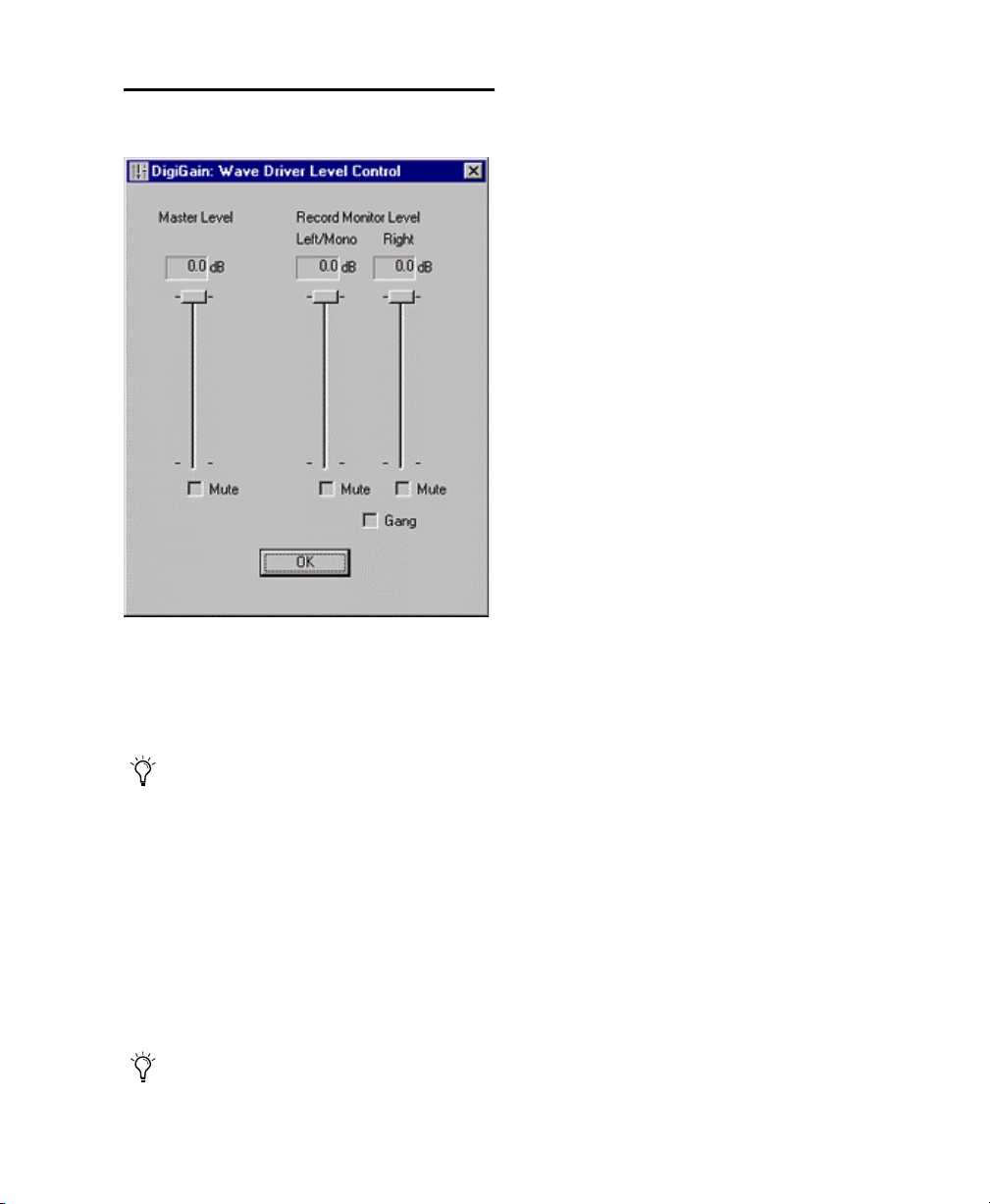
How to Use DigiGain
Figure 7. DigiGain WaveDriver Level Control
Record Monitor Mute
The Mute buttons under the Record Monitor
Level sliders individually mute the left and right
recording streams.
Gang
The Gang button groups the left and right
Record Monitor Level sliders and Mute buttons.
OK Button
Clicking on the OK button saves the volume settings. Volume settings are stored in a registry
key. This allows you to maintain the same volume level upon the next reboot or startup of the
system.
Master Level
This slider adjusts the output volume of channels 1–2 on your Digidesign audio interface.
During recording, this does not affect the
audio data being recorded.
Master Mute
The master mute option is enabled, output of
channels 1–2 of your audio interface will be
muted.
Record Monitor Level
These sliders adjust the output monitoring level
of the left and right recording channels.
As with the Master Level slider, these sliders
do not affect the audio data being recorded.
Appendix E: Digidesign WaveDriver (Windows Only) 91
Page 98

Getting Started with MIX92
Page 99

index
Numerics
1622 I/O 10, 28
connections & levels 2
Windows configuration 37
16-channel peripheral cable adapter 11, 29
882|20 I/O 10, 28
connections & levels 2
Windows configuration 36
888|24 I/O 10, 28
connections & levels 2
Windows configuration 36
A
ADAT Bridge I/O 10
connections & levels 2
adding
Master Fader tracks 65
adjusting track volume 53
Apple Sound Manager
using Digidesign hardware 83
Apple System software settings 11
application response
Windows configuration 24
arranging regions 62
assign a send 64
assigning a return
return
assigning on a track 65
ATTO
Macintosh configuration 72
Windows configuration 24
Audio Interface
cable 10, 28
connecting to Pro Tools|24 MIX systems 10,
28
primary 10, 28
requirements 2
Audio Regions List 56
Audio track 53
authorization code
Macintosh 17
Windows 33
B
backing up data 75
BIOS
Windows configuration 22
Bounce to Disk 67
dithering 68
C
cable length of SCSI drives 70
cannot create DAE deck 33
Channel Strip controls
Mute 64
Pan 64
Solo 64
Volume 64
clock master 9, 10, 27, 28
compatibility information for Pro Tools 3
computer requirements 3
configuring OMS 79
configuring the Digidesign Control Panel 83
connecting
effects units 42
external SCSI drive 71
SMPTE synchronization devices 44
studio 39
CPU requirements 3
creating a new track 52
creating playlists 63
Index 93
Page 100

D
d24 card 8, 26
DAE memory allocation 14
DAT recorder
connecting to Pro Tools 42
Digidesign Control Panel 83
configuring 83
Digidesign Control Panel install option 12
DigiGain 90
installing 90
removing 90
using 91
DigiSerial port 8, 26
DigiTest
error codes 77
Macintosh configuration 15
Windows configuration 32
DigiTranslator installation option 12
disabling Windows system sounds 86
disk space for audio tracks 70
dithering 68
DSP Farm 8, 27
E
Edit mode buttons 60
Edit modes 60
Edit Tools 60
editing regions 61
effects units, connecting to Pro Tools 42
error codes
DigiTest 77
error message number 4 33
expansion chassis
Macintosh configuration 7
Windows configuration 25
F
Flashing SCSI ROM 23
formatting a Windows hard drive 72
formatting hard drives
high-level 73
low-level 73
fragmentation 74
H
hard drives
maintenance 73
optimizing 74
requirements 4
hardware installation
Macintosh configuration 7
Windows configuration 25
Hardware Setup
Macintosh configuration 20
Windows configuration 35
HFS Drives, formatting 76
high-level formatting 73, 75
I
I/O Setup
Macintosh configuration 20
Windows configuration 37
IAC Driver 81
Import Audio From Other Movie command 56
importing audio 56
from CD (Macintosh) 56
from disk 56
Infinity symbol
removing from IAC Bus name 81
initializing a Macintosh drive 72
inserting a plug-in on a track 67
Installer CD 12
Windows configuration 29
installing
Pro Tools cards 9, 27
installing DigiGain 90
installing Pro Tools software
Macintosh configuration 11
Windows configuration 21
installing Surround Mixer
Macintosh configuration 13
Windows configuration 31
installing WaveDriver 86
L
low-level formatting 73
G
G3 computer requirements 4
Getting Started with MIX94
 Loading...