

Page 1
Digidesign® Plug-ins
Version 7.4
Page 2

Legal Notices
This guide is copyrighted ©2007 by Digidesign, a division of
Avid Technology, Inc. (hereafter “Digidesign”), with all rights
reserved. Under copyright laws, this guide may not be
duplicated in whole or in part without the written consent of
Digidesign.
003, 003 Rack, 96 I/O, 96i I/O, 192 Digital I/O, 192 I/O,
888|24 I/O, 882|20 I/O, 1622 I/O, 24-Bit ADAT Bridge I/O,
AudioSuite, Avid, Avid DNA, Avid Mojo, Avid Unity, Avid Unity
ISIS, Avid Unity MediaNetwork, Avid Xpress, AVoption,
AVoption|V10, Beat Detective, Bruno, Command|8, Control|24,
D-Command, D-Control, D-Fi, D-fx, D-Show, DAE, Digi 002,
Digi 002 Rack, DigiBase, DigiDelivery, Digidesign, Digidesign
Audio Engine, Digidesign Intelligent Noise Reduction,
Digidesign TDM Bus, DigiDrive, DigiRack, DigiTest,
DigiTranslator, DINR, DV Toolkit, EditPack, Impact, Interplay,
M-Audio, MachineControl, Maxim, Mbox, MediaComposer,
MIDI I/O, MIX, MultiShell, OMF, OMF Interchange, PRE,
ProControl, Pro Tools M-Powered, Pro Tools, Pro Tools|HD,
Pro Tools LE, QuickPunch, Reel Tape, Reso, Reverb One,
ReVibe, RTAS, Smack!, SoundReplacer, Sound Designer II,
Strike, Structure, SYNC HD, SYNC I/O, Synchronic, TL Space,
Velvet, and X-Form are trademarks or registered trademarks of
Digidesign and/or Avid Technology, Inc. All other trademarks
are the property of their respective owners.
Product features, specifications, system requirements, and
availability are subject to change without notice.
PN 9329-56817-00 REV A 07/07
Comments or suggestions regarding our documentation?
email: techpubs@digidesign.com
Page 3

contents
Chapter 1. Introduction . . . . . . . . . . . . . . . . . . . . . . . . . . . . . . . . . . . . . . . . . . . . . . . . . . . . . . 1
Contents of the Boxed Version of Your Plug-in . . . . . . . . . . . . . . . . . . . . . . . . . . . . . . . . . . . . 1
System Requirements . . . . . . . . . . . . . . . . . . . . . . . . . . . . . . . . . . . . . . . . . . . . . . . . . . . . . 2
Registering Your Plug-ins . . . . . . . . . . . . . . . . . . . . . . . . . . . . . . . . . . . . . . . . . . . . . . . . . . . 2
Working with Plug-ins . . . . . . . . . . . . . . . . . . . . . . . . . . . . . . . . . . . . . . . . . . . . . . . . . . . . . 2
Conventions Used in This Guide . . . . . . . . . . . . . . . . . . . . . . . . . . . . . . . . . . . . . . . . . . . . . . 3
About www.digidesign.com . . . . . . . . . . . . . . . . . . . . . . . . . . . . . . . . . . . . . . . . . . . . . . . . . 3
Chapter 2. Installation . . . . . . . . . . . . . . . . . . . . . . . . . . . . . . . . . . . . . . . . . . . . . . . . . . . . . . . 5
Installing Plug-ins . . . . . . . . . . . . . . . . . . . . . . . . . . . . . . . . . . . . . . . . . . . . . . . . . . . . . . . . 5
Authorizing Plug-ins. . . . . . . . . . . . . . . . . . . . . . . . . . . . . . . . . . . . . . . . . . . . . . . . . . . . . . . 6
Uninstalling Plug-ins . . . . . . . . . . . . . . . . . . . . . . . . . . . . . . . . . . . . . . . . . . . . . . . . . . . . . . 7
Chapter 3. Adjusting Plug-in Controls. . . . . . . . . . . . . . . . . . . . . . . . . . . . . . . . . . . . . . . . . . 9
Adjusting Plug-in Controls . . . . . . . . . . . . . . . . . . . . . . . . . . . . . . . . . . . . . . . . . . . . . . . . . . 9
Chapter 4. Bruno and Reso . . . . . . . . . . . . . . . . . . . . . . . . . . . . . . . . . . . . . . . . . . . . . . . . . . 11
DSP Requirements . . . . . . . . . . . . . . . . . . . . . . . . . . . . . . . . . . . . . . . . . . . . . . . . . . . . . . 12
Inserting Bruno/Reso onto an Audio Track. . . . . . . . . . . . . . . . . . . . . . . . . . . . . . . . . . . . . . 12
Playing Bruno/Reso. . . . . . . . . . . . . . . . . . . . . . . . . . . . . . . . . . . . . . . . . . . . . . . . . . . . . . 13
Using an External Key Input for Side-Chain Processing . . . . . . . . . . . . . . . . . . . . . . . . . . . . . 14
Bruno Controls . . . . . . . . . . . . . . . . . . . . . . . . . . . . . . . . . . . . . . . . . . . . . . . . . . . . . . . . . 15
Reso Controls . . . . . . . . . . . . . . . . . . . . . . . . . . . . . . . . . . . . . . . . . . . . . . . . . . . . . . . . . . 20
Contents iii
Page 4

Chapter 5. D-Fi. . . . . . . . . . . . . . . . . . . . . . . . . . . . . . . . . . . . . . . . . . . . . . . . . . . . . . . . . . . . . 27
Lo-Fi . . . . . . . . . . . . . . . . . . . . . . . . . . . . . . . . . . . . . . . . . . . . . . . . . . . . . . . . . . . . . . . . 28
Sci-Fi. . . . . . . . . . . . . . . . . . . . . . . . . . . . . . . . . . . . . . . . . . . . . . . . . . . . . . . . . . . . . . . . 30
Recti-Fi . . . . . . . . . . . . . . . . . . . . . . . . . . . . . . . . . . . . . . . . . . . . . . . . . . . . . . . . . . . . . . 32
Vari-Fi . . . . . . . . . . . . . . . . . . . . . . . . . . . . . . . . . . . . . . . . . . . . . . . . . . . . . . . . . . . . . . . 34
D-Fi Demo Session . . . . . . . . . . . . . . . . . . . . . . . . . . . . . . . . . . . . . . . . . . . . . . . . . . . . . . 35
Chapter 6. DINR . . . . . . . . . . . . . . . . . . . . . . . . . . . . . . . . . . . . . . . . . . . . . . . . . . . . . . . . . . . 39
Broadband Noise Reduction . . . . . . . . . . . . . . . . . . . . . . . . . . . . . . . . . . . . . . . . . . . . . . . 39
Broadband Noise Reduction Controls . . . . . . . . . . . . . . . . . . . . . . . . . . . . . . . . . . . . . . . . . 41
Using Broadband Noise Reduction . . . . . . . . . . . . . . . . . . . . . . . . . . . . . . . . . . . . . . . . . . . 45
Using BNR AudioSuite. . . . . . . . . . . . . . . . . . . . . . . . . . . . . . . . . . . . . . . . . . . . . . . . . . . . 48
Chapter 7. Impact . . . . . . . . . . . . . . . . . . . . . . . . . . . . . . . . . . . . . . . . . . . . . . . . . . . . . . . . . . 51
Impact Parameters. . . . . . . . . . . . . . . . . . . . . . . . . . . . . . . . . . . . . . . . . . . . . . . . . . . . . . 52
Using a Key Input for External Side-Chain Processing . . . . . . . . . . . . . . . . . . . . . . . . . . . . . . 55
Chapter 8. Maxim . . . . . . . . . . . . . . . . . . . . . . . . . . . . . . . . . . . . . . . . . . . . . . . . . . . . . . . . . . 57
About Peak Limiting . . . . . . . . . . . . . . . . . . . . . . . . . . . . . . . . . . . . . . . . . . . . . . . . . . . . . 58
Maxim Controls and Meters. . . . . . . . . . . . . . . . . . . . . . . . . . . . . . . . . . . . . . . . . . . . . . . . 59
Using Maxim . . . . . . . . . . . . . . . . . . . . . . . . . . . . . . . . . . . . . . . . . . . . . . . . . . . . . . . . . . 62
Chapter 9. Reverb One. . . . . . . . . . . . . . . . . . . . . . . . . . . . . . . . . . . . . . . . . . . . . . . . . . . . . . 63
A Reverb Overview . . . . . . . . . . . . . . . . . . . . . . . . . . . . . . . . . . . . . . . . . . . . . . . . . . . . . . 63
Reverb One Controls . . . . . . . . . . . . . . . . . . . . . . . . . . . . . . . . . . . . . . . . . . . . . . . . . . . . . 64
Chapter 10. ReVibe . . . . . . . . . . . . . . . . . . . . . . . . . . . . . . . . . . . . . . . . . . . . . . . . . . . . . . . . 73
Reverberation Concepts . . . . . . . . . . . . . . . . . . . . . . . . . . . . . . . . . . . . . . . . . . . . . . . . . . 74
Using ReVibe . . . . . . . . . . . . . . . . . . . . . . . . . . . . . . . . . . . . . . . . . . . . . . . . . . . . . . . . . . 75
Adjusting ReVibe Parameters . . . . . . . . . . . . . . . . . . . . . . . . . . . . . . . . . . . . . . . . . . . . . . 76
ReVibe Controls . . . . . . . . . . . . . . . . . . . . . . . . . . . . . . . . . . . . . . . . . . . . . . . . . . . . . . . . 77
ReVibe Room Types . . . . . . . . . . . . . . . . . . . . . . . . . . . . . . . . . . . . . . . . . . . . . . . . . . . . . 89
Digidesign Plug-ins Guideiv
Page 5

Chapter 11. Smack! . . . . . . . . . . . . . . . . . . . . . . . . . . . . . . . . . . . . . . . . . . . . . . . . . . . . . . . . 93
Using the Smack! Compressor/Limiter . . . . . . . . . . . . . . . . . . . . . . . . . . . . . . . . . . . . . . . . 94
Smack! Parameters. . . . . . . . . . . . . . . . . . . . . . . . . . . . . . . . . . . . . . . . . . . . . . . . . . . . . . 95
Using the Side-Chain Input in Smack! . . . . . . . . . . . . . . . . . . . . . . . . . . . . . . . . . . . . . . . . . 99
Chapter 12. SoundReplacer . . . . . . . . . . . . . . . . . . . . . . . . . . . . . . . . . . . . . . . . . . . . . . . . 101
Audio Replacement Techniques . . . . . . . . . . . . . . . . . . . . . . . . . . . . . . . . . . . . . . . . . . . . 101
SoundReplacer Controls. . . . . . . . . . . . . . . . . . . . . . . . . . . . . . . . . . . . . . . . . . . . . . . . . . 102
Using SoundReplacer. . . . . . . . . . . . . . . . . . . . . . . . . . . . . . . . . . . . . . . . . . . . . . . . . . . . 106
Getting Optimum Results with SoundReplacer . . . . . . . . . . . . . . . . . . . . . . . . . . . . . . . . . . 107
Using the Audio Files Folder for Frequently Used Replacement Files. . . . . . . . . . . . . . . . . . . 109
Chapter 13. X-Form Plug-in Parameters . . . . . . . . . . . . . . . . . . . . . . . . . . . . . . . . . . . . . . 111
X-Form . . . . . . . . . . . . . . . . . . . . . . . . . . . . . . . . . . . . . . . . . . . . . . . . . . . . . . . . . . . . . . 111
Appendix A. DSP Requirements for TDM Plug-ins . . . . . . . . . . . . . . . . . . . . . . . . . . . . . 119
DSP Requirements . . . . . . . . . . . . . . . . . . . . . . . . . . . . . . . . . . . . . . . . . . . . . . . . . . . . . 120
Appendix B. DSP Delays Incurred by TDM Plug-ins . . . . . . . . . . . . . . . . . . . . . . . . . . . . 125
Index . . . . . . . . . . . . . . . . . . . . . . . . . . . . . . . . . . . . . . . . . . . . . . . . . . . . . . . . . . . . . . . . . . . . 127
Contents v
Page 6

Digidesign Plug-ins Guidevi
Page 7

chapter 1
Introduction
Digidesign® plug-ins provide a comprehensive
set of digital signal processing tools for professional audio production.
Contents of the Boxed Version of Your Plug-in
This guide explains the use of each of the plugins currently available from Digidesign.
These plug-ins include:
•Bruno
• D-Fi™ creative sound design plug-ins
• DINR™ intelligent noise reduction
•Impact™
•Maxim™
• Reverb One™
• ReVibe™
•Smack!™
• SoundReplacer™
• X-Form™ high-quality time compression
®
ment plug-in
and expansion plug-in
References to Pro Tools LE™ in this guide
are usually interchangeable with Pro Tools
M-Powered™, except as noted in the
Pro Tools M-Powered Getting Started
Guide.
®
& Reso
cross-synthesis plug-ins
peak limiter/sound maximizer
drum and sound replace-
Boxed versions of plug-ins contains the following components:
• Installation disc
• One of the following authorization cards for
authorizing plug-ins with an iLok USB Smart
Key (not supplied):
• Activation Card with an Activation Code
– or –
•License Card
Chapter 1: Introduction 1
Page 8

System Requirements
Registering Your Plug-ins
To use Digidesign plug-ins, you need the following:
• An iLok USB Smart Key
• An iLok.com account for managing iLok licenses
• One of the following:
• A Digidesign-qualified Pro Tools|HD
tem or Pro Tools LE system.
• A Digidesign-qualified Pro Tools system
and a third-party software application that
supports the Digidesign TDM, RTAS
AudioSuite™ plug-in standards.
• A qualified Avid
Avid Xpress DV, or Avid DNA
dioSuite only)
• A Digidesign-qualified VENUE system
(TDM only)
• DVD drive for Installation disc (boxed version
of plug-in only)
• Internet access for software activation and
registration purposes
For complete system requirements visit the Digidesign website (www.digidesign.com).
®
Xpress®,
®
sys-
®
, or
®
system (Au-
Compatibility Information
Digidesign can only assure compatibility and
provide support for hardware and software it has
tested and approved.
If you purchased a download version of a plugin from the Digi-Store (www.digidesign.com),
you were automatically registered.
If you purchased a boxed version of a plug-in,
you will be automatically registered when you
authorize your plug-in (see “Authorizing Plugins” on page 6).
Registered users receive periodic software update and upgrade notices.
Please refer to the Digidesign website
(www.digidesign.com) for information on technical support.
Working with Plug-ins
Besides the information provided in this guide,
refer to the DigiRack Plug-ins Guide for general
information on working with plug-ins, including:
• Inserting Plug-ins on Tracks
• Clip Indicators
• The Plug-in Window
• Adjusting Parameters
• Automating Plug-ins
• Using the Librarian
For a list of Digidesign-qualified computers,
operating systems, hard drives, and third-party
devices, visit the Digidesign website
(www.digidesign.com).
Digidesign Plug-ins Guide2
Page 9
Conventions Used in This Guide
All Digidesign guides use the following conventions to indicate menu choices and key commands:
:
Convention Action
File > Save Choose Save from the
File menu
Control+N Hold down the Control
Control-click Hold down the Control
Right-click Click with the right
The following symbols are used to highlight important information:
User Tips are helpful hints for getting the
most from your Pro Tools system.
Important Notices include information that
could affect your Pro Tools session data or
the performance of your Pro Tools system.
key and press the N key
key and click the mouse
button
mouse button
About www.digidesign.com
The Digidesign website (www.digidesign.com) is
your best online source for information to help
you get the most out of your Pro Tools system.
The following are just a few of the services and
features available.
Product Registration Register your purchase online.
Support and Downloads Contact Digidesign
Technical Support or Customer Service; download software updates and the latest online
manuals; browse the Compatibility documents
for system requirements; search the online Answerbase or join the worldwide Pro Tools community on the Digidesign User Conference.
Training and Education Study on your own using
courses available online or find out how you can
learn in a classroom setting at a certified
Pro Tools training center.
Products and Developers Learn about Digidesign
products; download demo software or learn
about our Development Partners and their plugins, applications, and hardware.
News and Events Get the latest news from
Digidesign or sign up for a Pro Tools demo.
Shortcuts show you useful keyboard or
mouse shortcuts.
Cross References point to related sections in
this guide and other Digidesign guides.
To learn more about these and other resources
available from Digidesign, visit the Digidesign
website (www.digidesign.com).
Chapter 1: Introduction 3
Page 10

Digidesign Plug-ins Guide4
Page 11

chapter 2
Installation
Installing Plug-ins
Installers for your plug-ins can be downloaded
from the DigiStore (www.digidesign.com) or
can be found on the plug-in installer disc (included with boxed versions of plug-ins).
An installer may also be available on a Pro Tools
installer disc or on a software bundle installer
disc.
Installation steps are essentially the same, regardless of the package, system, or bundle.
Updating Older Plug-ins
Because the Digidesign Plug-in installers contain the latest versions of the Digidesign plugins, use them to update any plug-ins you already
own.
Be sure to use the most recent versions of
Digidesign plug-ins available from the
Digidesign website (www.digidesign.com).
Installation
To install a plug-in:
1 Do one of the following:
• Download the installer for your computer
platform from the Digidesign website
(www.digidesign.com). After downloading,
make sure the installer is uncompressed
(.ZIP on Windows or .SIT on Mac).
– or –
• Insert the Installer disc into your computer.
2 Double-click the plug-in installer application.
3 Follow the on-screen instructions to complete
the installation.
4 When installation is complete, click Finish
(Windows) or Quit (Mac).
When you open Pro Tools, you are prompted to
authorize your new plug-in.
Chapter 2: Installation 5
Page 12
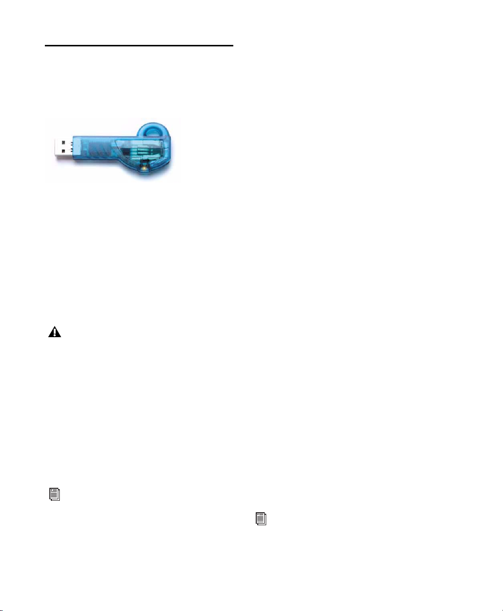
Authorizing Plug-ins
Digidesign plug-ins are authorized using the
iLok USB Smart Key (iLok), manufactured by
PACE Anti-Piracy, Inc.
iLok USB Smart Key
The iLok is similar to a dongle, but unlike a dongle, it is designed to securely authorize multiple
software applications from a variety of software
developers.
This key can hold over 100 licenses for all of
your iLok-enabled software. Once an iLok is authorized for a given piece of software, you can
use the iLok to authorize that software on any
computer.
The iLok USB Smart Key is not supplied
with your plug-in or software option. You
can use the one included with certain
Pro Tools systems (such as Pro Tools|HDseries systems), or purchase one separately.
Authorizing Download Versions of Plug-ins
If you purchased a download version of a plugin from the DigiStore (www.digidesign.com),
authorize the plug-in by downloading licenses
from iLok.com to an iLok.
See the
iLok Usage Guide for details, or visit
the iLok website (www.iLok.com).
Authorizing Boxed Versions of Plug-ins
If you purchased a boxed version of a plug-in, it
comes with either an Activation Code (on the
included Activation Card) or an iLok License
card:
• To authorize plug-ins using an Activation
Code, see “Authorizing Plug-ins Using an Activation Code” on page 6.
• To authorize plug-ins using an iLok License
Card, see “Authorizing Plug-ins Using a License Card” on page 7.
Authorizing Plug-ins Using an Activation Code
To authorize a plug-in using an Activation Code:
1 If you do not have an existing iLok.com ac-
count, visit www.iLok.com and sign up for an
iLok.com account.
2 Transfer the license for your plug-in to your
iLok.com account by doing the following:
• Visit http://secure.digidesign.com/
activation.
• Input your Activation Code (listed on your
Activation Card) and your iLok.com User
ID. Your iLok.com User ID is the name you
create for your iLok.com account.
3 Transfer the licenses from your iLok.com ac-
count to your iLok USB Smart Key by doing the
following:
• Insert the iLok into an available USB port
on your computer.
• Go to www.iLok.com and log in.
• Follow the on-screen instructions for transferring your licences to your iLok.
For information about iLok technology and
licenses, see the electronic PDF of the iLok
Usage Guide.
Digidesign Plug-ins Guide6
Page 13

4 Launch Pro Tools.
5 If you have any installed unauthorized plug-
ins or software options, you are prompted to authorize them. Follow the on-screen instructions
to complete the authorization process.
Authorizing Plug-ins Using a License Card
License Cards are specific to each plug-in or software option. You will receive the appropriate License Cards for the plug-ins that you purchase.
License Cards have a small punch-out plastic
chip called a GSM cutout.
The authorization steps in this section must be
repeated for purchased plug-in.
For additional information about iLok technology and authorizations, see the electronic PDF of the iLok Usage Guide.
To authorize a plug-in using a License Card:
1 Insert the iLok into an available USB port on
your computer.
2 Launch Pro Tools. You are prompted to autho-
rize any installed unauthorized plug-ins or software options.
If you are already using a demo version of
the plug-in or software option, launch
Pro Tools before you insert the iLok, then insert the iLok into any available USB port
when prompted by Pro Tools.
3 Follow the on-screen instructions until you
are prompted to insert the License Card into the
iLok.
4 Separate the GSM cutout from the larger pro-
tective card by pulling it up and out with your
thumb. Do not force the cutout down with your
finger.
5 Insert the GSM cutout into the iLok. Visually
verify that the metal portion of the cutout
makes contact with the iLok’s metal card reader.
iLok with License Card
6 Follow the on-screen instructions to complete
the authorization process for each plug-in.
7 After the authorization has completed, re-
move the GSM cutout from the iLok. (If you
have to remove the iLok from the computer to
remove the cutout, be sure to re-insert the iLok
in any available USB port on your computer
when you are finished.)
Uninstalling Plug-ins
If you need to uninstall a plug-in from your system, follow the instructions below for your
computer platform.
Windows Vista
To remove a plug-in:
1 Choose > Control Panel.
2 Under Programs, click “Uninstall a Program.
3 Select the plug-in from the list of installed ap-
plications.
4 Click Uninstall.
5 Follow the on-screen instructions to remove
the plug-in.
Chapter 2: Installation 7
Page 14

Windows XP
Mac OS X
To remove a plug-in:
1 Choose Start Control Panel.
2 Double-click Add or Remove Programs.
3 Select the plug-in from the list of installed ap-
plications.
4 Click the Remove button.
5 Follow the on-screen instructions to remove
the plug-in.
To remove a plug-in:
1 Locate and open the Plug-ins folder on your
Startup drive (Library/Application Support/
Digidesign/Plug-ins).
2 Do one of the following:
• Drag the plug-in to the Trash and empty
the Trash.
– or –
• Drag the plug-in to the Plug-ins (Unused)
folder.
Digidesign Plug-ins Guide8
Page 15

chapter 3
Adjusting Plug-in Controls
Adjusting Plug-in Controls
You can adjust plug-in controls by dragging the
control’s slider or knob, or by typing a value
into the control’s text box. Additionally, some
plug-ins have switches that can be enabled by
clicking on them.
To adjust a plug-in control:
1 Begin audio playback so that you can hear the
control changes in real time.
2 Adjust the controls of the plug-in for the effect
you want. Refer to “Adjusting Controls Using a
Mouse” on page 9 and “Editing Parameters Using a Computer Keyboard” on page 10.
Closing the plug-in will save the most recent
changes.
Adjusting Controls Using a Mouse
You can adjust rotary controls by dragging horizontally or vertically. Parameter values increase
as you drag upward or to the right, and decrease
as you drag downward or to the left.
Keyboard Shortcuts
For finer adjustments, Control-drag (Win-
dows) or Command-drag (Mac) the control.
To return a control to its default value, Alt-
click (Windows) or Option-click (Mac) the control.
Chapter 3: Adjusting Plug-in Controls 9
Page 16

Editing Parameters Using a Computer Keyboard
Editing Parameters Using a Scroll Wheel
Some controls have text boxes that display the
current value of the parameter. You can edit the
numeric value of a parameter with your computer keyboard.
If multiple Plug-in windows are open, Tab and
keyboard entry remain focused on the plug-in
that is the target window.
To change control values with a computer
keyboard:
1 Click the text box corresponding to the con-
trol that you want to adjust.
2 Change the value.
• To increase a value, press the Up Arrow on
your keyboard. To decrease a value, press
the Down Arrow on your keyboard.
– or –
• Type the value.
In fields that support values in kilohertz,
typing “k” after a number value will multiply the value by 1,000. For example, type
“8k” to enter a value of 8,000.
Some controls have text boxes that display the
current value of the parameter. You can edit the
numeric value of a parameter using a scroll
wheel.
To change control values using a scroll wheel:
1 Click the text box corresponding to the con-
trol that you want to adjust.
2 To increase a value, scroll up with the scroll
wheel. To decrease a value, scroll down with the
scroll wheel.
Toggling Switches
To toggle a switch:
Click the switch on-screen.
3 Do one of the following:
• Press Enter on the numeric keyboard to input the value and remain in keyboard editing mode.
– or –
• Press Enter on the alpha keyboard (Windows) or Return (Mac) to enter the value
and leave keyboard editing mode.
To move forward through the different control fields, press the Tab key. To move backward, press Shift+Tab.
Digidesign Plug-ins Guide10
Page 17

chapter 4
Bruno and Reso
Bruno and Reso are a pair of TDM plug-ins that
process audio using a sound generation technique known as cross-synthesis.
Cross-synthesis generates complex sound textures by using an audio track as a tone source
then applying a variety of synthesizer-type effects to that tone source.
Bruno and Reso each use a different sound generation method:
Bruno uses time-slicing, a technique whereby
timbres are extracted from the source audio during playback and crossfaded together. This
crossfading between signals can create a rhythmic pulse in the sound as the timbre changes.
Reso uses a resonator, which adds harmonic
overtones to the source audio through a short
signal delay line with a feedback loop.
In both cases, the processed sound can then be
played in real time or sequenced using the MIDI
recording and playback capabilities of Pro Tools.
Maximum Voices with HD Accel Card
Bruno and Reso on Pro Tools|HD systems
equipped with an HD Accel card offer up to 62
voices of polyphony at the maximum voice setting (at 44.1 kHz and 48 kHz).
Bruno features include:
• Time-slice tone generation with adjustable
crossfade
• Polyphony: Up to 62 voices of polyphony
(on Pro Tools|HD Accel systems)
• Multi-voice detuning
• Editable ADSR envelope generator
•Portamento
• Velocity-sensitive gain and detuning
• Time-slice switching using envelope triggering or MIDI beat clock
• Voice-stacking
• Side-chain input for control using an external audio source
• Supports sample rates up to 192 kHz
• Online help
Chapter 4: Bruno and Reso 11
Page 18

Reso features include:
• Harmonic resonance generation
• Up to 62 voices of polyphony (on
Pro Tools|HD Accel systems)
• Multi-voice detuning
• Resonant low-pass filter
• Editable ADSR envelope generator
•Portamento
• Velocity-sensitive resonance, damping,
gain, and detuning
• Harmonic switching using envelope triggering or MIDI beat clock
• Voice-stacking
• Side-chain input for control using an external audio source
• Supports sample rates up to 192 kHz
• Online help
DSP Requirements
Bruno and Reso each require one full DSP chip
on a Pro Tools|HD card.
DSP and Voice Polyphony
The maximum number of Bruno/Reso voices
available per DSP chip depends on the sample
rate of the session and the type of DSP cards in
your system.
HD Core and HD Process On Pro Tools|HD systems not equipped with an HD Accel card,
Bruno and Reso provide a maximum of 24
voices of polyphony. Polyphony is reduced by
half for sessions at 88.2 kHz and 96 kHz (up to
14 voices).
Inserting Bruno/Reso onto an Audio Track
To use Bruno/Reso in a Pro Tools session, you
must add it to a track as an insert. Once
Bruno/Reso is inserted on the track, you can adjust its controls to get the effect that you want,
then play the plug-in using the on-screen keyboard, an external MIDI controller, or an Instrument track.
To add Bruno/Reso as a track Insert:
1 Click the Insert selector on the desired track
and select Bruno or Reso.
2 Click Play on the Pro Tools Transport to start
audio playback.
3 Play Bruno/Reso with the on-screen keyboard
or by MIDI control. See “Playing Bruno/Reso”
on page 13.
4 Adjust Bruno/Reso controls to get the effect
you want.
HD Accel On Pro Tools|HD systems equipped
with an HD Accel card, Bruno and Reso provide
up to 62 voices at their maximum setting. The
62-voice versions of Bruno and Reso require one
entire DSP chip on an HD Accel card. Polyphony is reduced by half for sessions at 88.2 kHz
and 96 kHz.
Digidesign Plug-ins Guide12
Page 19

Playing Bruno/Reso
To generate sound, Bruno/Reso must be played
during audio playback. You can play
Bruno/Reso in two ways:
In real time, using either the on-screen key-
board or an external MIDI controller.
– or –
Using MIDI
Using the On-Screen Keyboard
The simplest way to play Bruno/Reso is to use its
on-screen keyboard. You can click one note at a
time or use keyboard latch to hold multiple
notes.
Notes played with the on-screen keyboard are
triggered at a MIDI velocity of 92.
To play Bruno/Reso with the on-screen keyboard:
1 Open the plug-in window for Bruno/Reso.
2 Click Play on the Pro Tools Transport to start
audio playback.
3 Click the on-screen keyboard. Bruno/Reso will
only produce sound while audio plays on the
source track.
To latch keys on the on-screen keyboard:
1 Click the Latch bar, then click multiple keys.
Chords can be played in this way.
2 To turn off a latched key, click it a second
time.
Using MIDI
You can play Bruno/Reso live using a MIDI keyboard controller. You can also use the MIDI keyboard controller to record your performance on
an Instrument track or a MIDI track routed to
Bruno/Reso for playback.
To configure Bruno/Reso for MIDI input:
1 Insert Bruno/Reso on an audio track.
2 Choose Track > New and specify 1 new Instru-
ment or MIDI track, then click Create. Create a
separate Instrument or MIDI track for each
Bruno/Reso plug-in you use.
3 Click the track’s MIDI Output selector and
choose Bruno or Reso.
If you are using multiple Bruno/Reso plug-ins,
they will all appear in this pop-up. Route the Instrument or MIDI track to the correct one.
4 Record-enable the Instrument or MIDI track.
5 Test your MIDI connection by playing notes
on your MIDI keyboard. The corresponding
notes should highlight on Bruno/Reso’s onscreen keyboard.
To play Bruno/Reso with a MIDI controller:
1 Start audio playback.
2 Play your MIDI keyboard while audio plays.
Bruno/Reso only produces sound during audio
playback on the source track.
3 To turn off key latching entirely, click the
Latch bar a second time.
Saving a Bruno or Reso setting while keys
are latched also saves the latched keys.
Chapter 4: Bruno and Reso 13
Page 20
Using MIDI Playback
You can also play Bruno/Reso using a Pro Tools
Instrument or MIDI track. Use a separate Instrument or MIDI track for each Bruno/Reso plug-in.
To play Bruno/Reso using an Instrument or MIDI
track:
1 Insert Bruno or Reso on an audio track.
2 Click the Instrument or MIDI track’s MIDI
Output selector and choose Bruno or Reso. If
you are using multiple Bruno or Reso plug-ins,
they will all appear in this pop-up. Route the Instrument or MIDI track to the correct one.
3 Start Pro Tools playback.
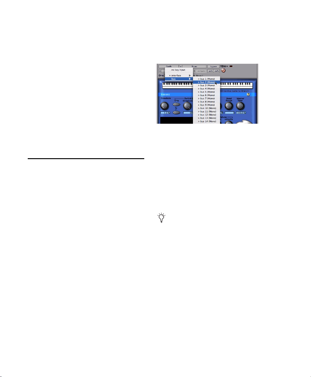
To use a key input for side-chain processing:
1 Click the Key Input selector and choose the
input or bus with the audio you want to use to
trigger the plug-in.
Selecting a Key Input
2 Click the Key Input button (the button with
the key icon above it) to activate external sidechain processing.
Using an External Key Input for Side-Chain Processing
Bruno and Reso feature side-chain processing
capabilities. Side-chain processing lets you trigger certain controls from a separate reference
track or external audio source. The source used
for triggering is referred to as the key input.
You can use this capability to control the rate at
which Bruno performs sample switching or Reso
toggles its harmonics back and forth using the
dynamics of another signal (the key input).
Typically, a rhythm track such as a drum kit is
used to trigger these controls and create rhythmic timbral changes that match the groove of
the key input.
3 Begin playback. The plug-in uses the input or
bus that you chose as a side-chain input to trigger the effect.
4 To hear the audio source you have selected to
control side-chain input, click the Key Listen
button (the button below the Ear icon).
Remember to disable Key Listen to resume
normal plug-in monitoring.
5 Adjust other controls to create the desired ef-
fect.
Digidesign Plug-ins Guide14
Page 21
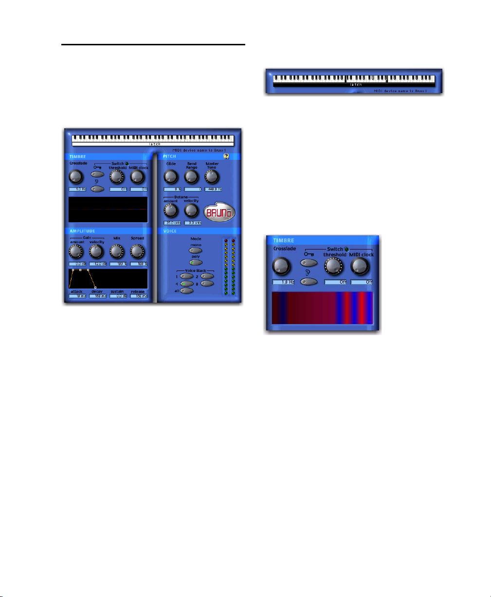
Bruno Controls
Bruno uses time-slicing for tone generation, extracting timbres from the audio track during
playback and cross-fading them together at a
user-selectable rate.
Bruno
This crossfading can create a rhythmic pulse in
the sound as the timbre changes. This makes
Bruno ideal for creating tonal effects with a continuously shifting timbre—similar to the wave
sequencing found on synthesizers such as the
PPG, Prophet VS, Korg Wavestation, and Waldorf XT.
By carefully choosing the type of source audio,
the crossfade length, and the type of switching,
you can create unique and complex sound textures.
On-Screen Keyboard
The on-screen keyboard
The simplest way to play Bruno is to use its onscreen keyboard. You can click one note at a
time or use keyboard latch to hold multiple
notes.
Notes played with the on-screen keyboard are
triggered at a MIDI velocity of 92.
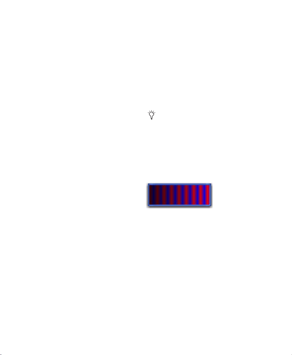
Timbre Controls
Timbre controls
Crossfade
Crossfade sets the rate at which Bruno extracts
timbres from the source audio and crossfades
from one time slice to the next. The range of this
control is from 2 to 40 Hz (cycles per second) in
a 44.1 kHz or 48 kHz session, and from 4 to 40
Hz in a 96 kHz session.
The higher the crossfade frequency, the smaller
the time slice, and the faster Bruno moves between slices. A higher frequency crossfade
would retain more characteristics of the original
audio source and would have a pulsed or wavesequenced feel.
Chapter 4: Bruno and Reso 15
Page 22
The lower the crossfade frequency, the larger the
time slice, and the slower Bruno moves between
slices. A lower frequency crossfade would have
fewer characteristics of the original source and a
more rounded or gradually evolving sound.
Switch
Switch causes Bruno to switch directly between
time-sliced samples without crossfading them.
This adds a distinct rhythmic pulse to the timbral changes.
used, the dynamics of the key input signal will
trigger switching. Threshold-based switching
can be used at the same time as Key Input-based
switching.
MIDI Clock Triggers switching in sync with a
MIDI Beat Clock signal. This creates a very regular, highly rhythmic wave sequencing effect
that is ideal for sessions arranged around MIDI
beat clock. This control can be set to quarter,
eighth, or sixteenth notes, or dotted triplet values of the same.
Switching can be controlled by triggering (using
the dynamics of the source audio or an external
key input) or by MIDI clock.
External Key Enables switching from a separate
reference track or external audio source. The
so urce use d for tri ggeri ng is r ef err ed to a s the key
input and is selected using the Side-chain Input
pop-up. You can assign either an audio input
channel or a TDM bus channel.
Typically, a drum track is used as a key input so
that switching occurs according to a definite
rhythmic pattern.
Key Listen When enabled, Key Listen monitors
the source of the key input. It is often useful to
do this in order to fine tune Bruno’s settings to
the key input. See “Using an External Key Input
for Side-Chain Processing” on page 14.
Threshold Sets the level in decibels above which
switching occurs. When the audio input level
rises above the Threshold level, Bruno will
switch directly to a new time-slice. The range of
this control is from a low of –48 dB (maximum
switching) to a high of 0.0 dB (no switching). If
no key input is used, the dynamics of the source
audio will trigger switching. If a key input is
For quick numeric entry of MIDI beat clock
values, type “4,” “8,” or “16” for quarter
notes, eight notes, or sixteenth notes. Add
“t” for triplets, or “d” for dotted note values.
Typing “4t” for example, enters a quarter
note triplet value. Typing “16d” enters a
dotted sixteenth note value.
Timbrometer
Timbrometer
This multicolor waveform display shows the
amplitude and duration of the audio signal generated by Bruno as well as the frequency of timbral changes and whether they are crossfaded or
switched.
Red and blue waveform segments indicate timbral changes that are crossfaded. Green waveform segments indicate timbral changes that are
hard switched.
Digidesign Plug-ins Guide16
Page 23
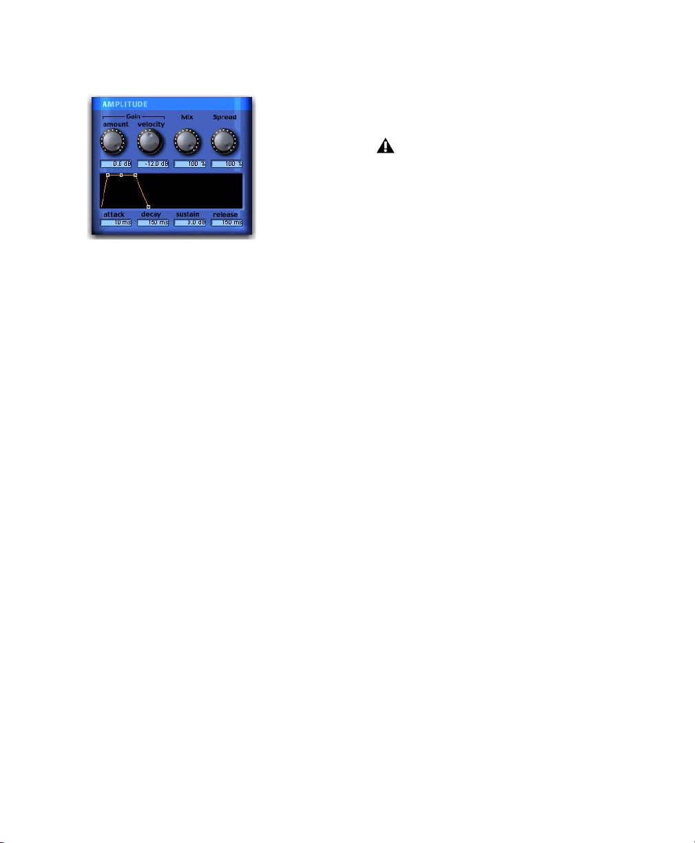
Amplitude Controls
Conversely, if Gain Velocity is set to 0.0 dB,
Bruno’s volume will not change no matter how
hard or soft you strike a key on your MIDI controller.
Gain Velocity only has an effect when you
play Bruno with a velocity-sensitive MIDI
controller.
Mix
Amplitude controls
Gain Amount
Gain Amount attenuates output level gain.
Since some of Bruno’s controls can cause extreme changes in signal level, this is particularly
useful for preventing clipping and achieving
unity gain with the original signal level. This
control is adjustable from a low of –96 dB (no
gain) to a high of 0.0 dB (maximum gain).
Gain Velocity
Gain Velocity sets the velocity sensitivity of the
Gain Amount control. This gives you touch-sensitive control over Bruno’s volume using a MIDI
keyboard.
This control is adjustable from a low of –24 dB
(maximum velocity sensitivity) to a high of
0.0 dB (no velocity sensitivity).
If you set Gain Velocity to –24 dB, a soft strike
on a key will reduce gain up to –24 dB. A hard
strike will have a maximum output level equal
to the current dB setting of the Gain Amount
control.
Mix adjusts the mix of the processed audio with
the original, unprocessed audio.
Spread
When Bruno is used in stereo, the Spread control can be used to pan multiple voices within
the stereo field. This control is adjustable from
0% (no stereo spread) to 100% (maximum stereo
spread).
Voice stacking has a direct effect on stereo
Spread. For example, setting Voice Stack to 1
and Spread to 100% will randomly pan each
note played. Setting Voice Stack to 4 and Spread
to 100%, will pan two of the four voices hard
left, and two voices hard right.
ADSR Envelope Generator
The ADSR (attack, decay, sustain, release) Envelope Generator controls Bruno’s amplitude envelope. This amplitude envelope is applied to a
sound each time a note is struck.
The four envelope elements can be adjusted by
dragging the appropriate breakpoint, or by typing in a numeric value.
Attack Controls the amount of time in milliseconds that the sound takes to rise from zero amplitude to its full level. The longer the attack, the
more time it takes for the sound to reach maximum volume after the a note is struck. This control is adjustable from 0.0 to 5000 milliseconds.
Chapter 4: Bruno and Reso 17
Page 24
Decay Controls the amount of time in milliseconds that the sound takes to fall from its peak
Attack level to the Sustain level. This control is
adjustable from 0.0 ms to 5000 ms.
Sustain Level Controls the amplitude level in dB
that is reached after the decay time has elapsed.
The amplitude level stays constant as long as a
MIDI note remains depressed. This control is adjustable from –96 dB (no sustain) to 0.0 dB
(maximum sustain).
Release Controls the amount of time in milliseconds that the sound takes to fall from the
Sustain level to zero amplitude after a note is released. This control is adjustable from 0.0 ms to
5000 ms.
Bend Range
Bend Range sets the maximum interval of pitch
bend that can be applied to Bruno with a MIDI
controller’s pitch bend wheel. This control is adjustable from 0 semitones (no bend) to 12 semitones (1 octave).
Master Tune
Master Tune can be used to tune the pitch of
Bruno’s output to another instrument. By default, this control is set to 440.0 Hz It can be adjusted from a low of 430.0 Hz to a high of
450.0 Hz.
Detune Amount
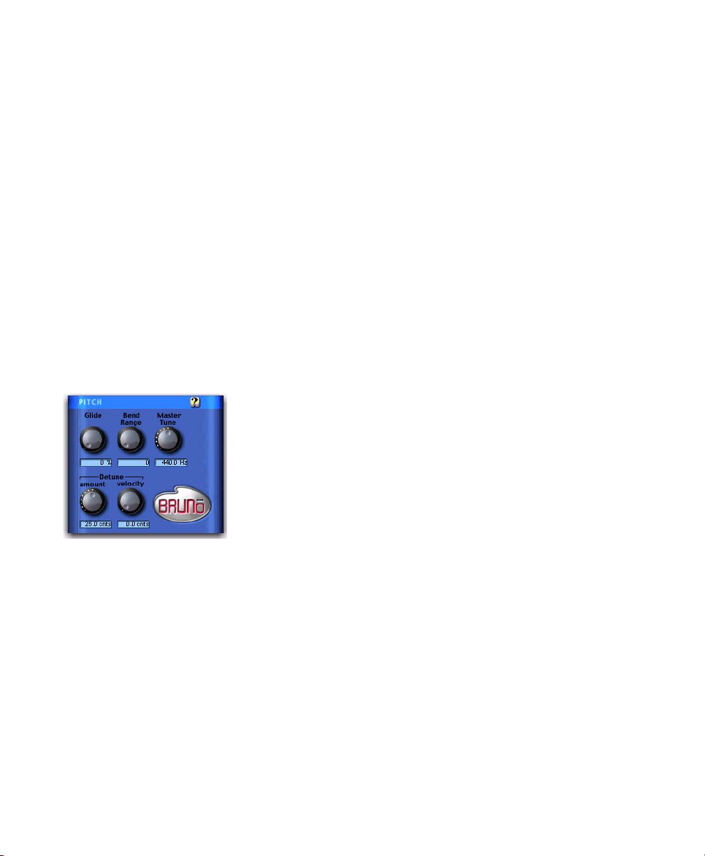
Pitch Controls
Pitch controls
Glide
Glide, also known as portamento, determines the
amount of time it takes for a pitch to glide from
the current note to the next note played. This effect is commonly found on synthesizers.
Glide is adjustable from a low of 0.0% (no glide)
to a high of 100% (maximum glide). A setting of
100% will take the longest time to travel from
the current note to the next note played. The effect is also dependent on the interval (distance
of pitch) between the two notes: The larger the
interval, the more noticeable the effect.
Detuning is a common sound-thickening technique used on synthesizers and many effects devices. Bruno’s Detune Amount control sets the
maximum amount of pitch detuning that occurs when multiple voices are stacked together
using Voice Stacking. Using a combination of
voice stacking and detuning, you can create timbres that are exceptionally fat.
Voices can be detuned up to 50.0 cents. (One
cent is equal to 1/100th of a semitone.)
Detune Velocity
Detune Velocity controls how MIDI key velocity
affects voice detuning. This gives you velocitysensitive control over voice detuning when you
play Bruno with a MIDI keyboard.
This control is adjustable from a low of 0.0 cents
(no velocity-sensitive detuning) to a high of
50.0 cents (maximum velocity-sensitive detuning).
Digidesign Plug-ins Guide18
Page 25
If Detune Velocity is set to 0.0 cents, detuning
will not change no matter how hard you strike a
key on your MIDI controller. Conversely, if you
set Detune Velocity to 50.0 cents, a hard strike
will detune voices a maximum of 50.0 cents (in
addition to the detuning specified with the Detune Amount control).
Detune Velocity has an effect only when
you play Bruno with a velocity-sensitive
MIDI controller.
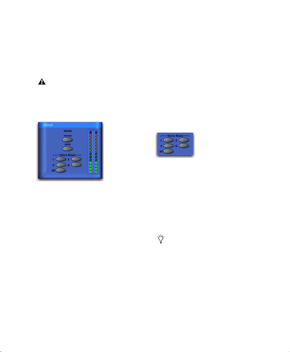
Voice Controls
Voice controls
These controls set Bruno’s voice polyphony and
allocation.
Mode
Mono (Monophonic)
In this mode, Bruno responds monophonically,
producing a single note even if more than one is
played simultaneously (though multiple voices
can be stacked on the same note using the Voice
Stacking control). Monophonic mode gives
voice priority to the most recently played note.
Poly (Polyphonic)
In this mode, Bruno responds polyphonically,
producing as many notes as are played simultaneously (up to 62 on Pro Tools|HD Accel systems). The number of notes that can be played
simultaneously depends on the Voice Stacking
setting chosen. A voice stack setting of 1, for example, allows up to 62 individual notes simultaneously. A voice stack setting of All allows only
one note at a time, but will stack all 62 voices on
that note, producing an extremely fat sound.
Voi ce Sta ck
Voice Stack selects the number of voices that are
used, or stacked when you play a single note. The
number of voices that you choose to stack will
directly affect polyphony. Selecting a larger
number of stacked voices will reduce the number of notes that you can play simultaneously.
Voice Stack
The sample rate of your session also affects polyphony. For example, in a 96 kHz session,
Bruno can simultaneously play up to:
• 32 notes in a 1-voice stack
• 16 notes in a 2-voice stack
• 4 notes in a 4-voice stack
• 2 notes in an 8-voice stack
• 1 note in an 12-voice (All) stack
The 62-voice Bruno requires an HD Accel
card.
In a 44.1 kHz or 48 kHz session on a
Pro Tools|HD system not equipped with an
HD Accel card, Bruno can simultaneously play
up to:
• 24 notes in a 1-voice stack
• 12 notes in a 2-voice stack
• 6 notes in a 4-voice stack
• 3 notes in an 8-voice stack
• 1 note in a 24-voice (All) stack
Chapter 4: Bruno and Reso 19
Page 26
Voice counts for Bruno for 44.1 kHz and 48 kHz
sessions are the same on Pro Tools|HD-series systems not equipped with an HD Accel card.
If all available voices are being used, playing an
additional note will replace the first note played
in the chord.
Online Help
Online help
On-Screen Keyboard
On-screen keyboard
The simplest way to play Reso is to use its onscreen keyboard. You can click one note at a
time or use keyboard latch to hold multiple
notes.
Notes played with the on-screen keyboard are
triggered at a MIDI velocity of 92.
To use online help, click the name of any control or parameter and an explanation will appear. Clicking the Online Help button itself provides more details on using this feature.
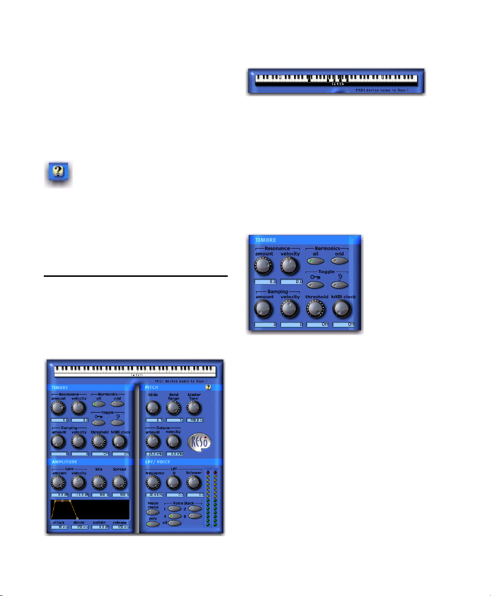
Reso Controls
Reso synthesizes new harmonic overtones from
the source audio signal, creating harmonically
rich timbres with a metallic, synthesizer-like
character.
Timbre Controls
Timbre controls
Resonance Amount
Resonance Amount controls the intensity of
harmonic overtones produced by the Resonator.
Increasing the Resonance Amount will increase
the overall harmonic content of the sound
while increasing the sustained portions of the
generated harmonics.
The frequency content of the input signal
largely determines what harmonics are generated by the resonator. For this reason, the character of the resonance will change according to
the type of audio that you process.
Reso
Digidesign Plug-ins Guide20
Page 27
Resonance Velocity
Damping Velocity
Resonance Velocity increases or decreases resonance according to how hard a MIDI key is
struck and how much resonance is initially specified with the Resonance Amount control.
Resonance Velocity is adjustable from a low of
–10 to a high of +10. With positive values, the
harder the key is struck, the more resonance is
applied. With negative values, the harder the
key is struck, the less resonance is applied.
The effectiveness of this control depends on the
Resonance Amount setting. For example, if Resonance Amount is set to 0, setting the Resonance Velocity to a negative value will have no
effect, since there is no resonance to remove.
Similarly, if the Resonance Amount control is
set to 10, setting Resonance Velocity to +10 will
have no effect since the resonance is already at
its maximum.
For optimum effect, set the Resonance Amount
to a middle value, then set Resonance Velocity
accordingly for the desired effect.
Resonance Velocity has an effect only when
you play Reso with a velocity-sensitive
MIDI controller.
Damping Amount
Damping causes the high-frequency harmonics
of a sound to decay more rapidly than the low
frequency harmonics. It lets you control the
brightness of the signal generated by Reso's Resonator and is particularly useful for creating
harp or plucked string-like textures.
The range of this control is from 0 (no damping)
to 10 (maximum damping). The greater the
amount of damping, the faster the high-frequency harmonics in the audio will decay and
the duller it will sound.
Damping Velocity increases or decreases damping according to how hard a MIDI key is struck
and how much damping is initially specified
with the Damping Amount control.
Damping Velocity is adjustable from a low of
–10 to a high of +10. With positive values, the
harder the key is struck, the more damping is applied. With negative values, the harder the key is
struck, the less damping is applied (which simulates the behavior of many real instruments).
The effectiveness of this control depends on the
Damping Amount setting. For example, if
Damping Amount is set to zero, setting the
Damping Velocity to a negative value will have
no effect, since there is no damping to remove.
Similarly, if the Damping Amount control is set
to 10, setting Damping Velocity to +10 will have
no effect since damping is already at its maximum.
For optimum effect, set the Damping Amount to
a middle value, then set Damping Velocity accordingly for the desired effect.
Damping Velocity only has an effect when
you play Reso with a velocity-sensitive
MIDI keyboard controller.
Harmonics
The resonator adds harmonic overtones to the
source audio signal that are integer multiples of
the fundamental frequency of the signal. The
Harmonics control selects between all of these
harmonics, or just the odd-numbered intervals.
Your choice will affect the timbre of the sound.
All Adds all of the harmonic overtones generated by the resonator. In synthesizer parlance,
this produces a somewhat buzzier, sawtooth
wave-like timbre.
Chapter 4: Bruno and Reso 21
Page 28

Odd Adds only the odd-numbered harmonic
overtones generated by the resonator. In synthesizer parlance, this produces a somewhat more
hollow, square wave-like timbre.
Tog gle
Reso can automatically toggle between the All
and Odd harmonics settings, producing a rhythmic pulse in the timbre.
Harmonic toggling can be controlled either by
triggering (using the dynamics of the source audio itself, or those of an external key input) or by
MIDI Beat Clock.
External Key Toggles the harmonics from a separate reference track or an external audio source.
The source used for toggling is referred to as the
key input and is selected using the Side-chain Input pop-up. You can assign either an audio input channel or a TDM bus channel.
Typically, a drum track is used as a key input so
that toggling occurs according to a definite
rhythmic pattern.
MIDI Clock Triggers toggling in sync with a
MIDI Beat Clock signal. This creates a very regular, highly rhythmic wave sequencing effect
that is ideal for sessions arranged around MIDI
beat clock. This control can be set to quarter,
eighth, or sixteenth notes, or dotted triplet values of the same.
For quick numeric entry of MIDI beat clock
values, type “4,” “8,” or “16” for quarter
notes, eight notes, or sixteenth notes. Add
“t” for triplets, or “d” for dotted note values.
Typing “4t” for example, enters a quarter
note triplet value. Typing “16d” enters a
dotted sixteenth note value.
Amplitude Controls
Key Listen When enabled, monitors the source
of the key input. It is useful to do this to fine
tune Reso’s settings to the key input.
See “Using an External Key Input for SideChain Processing” on page 14.
Threshold Sets the level in decibels above which
toggling occurs. When the audio input level
rises above the Threshold level, Reso will toggle
its harmonics setting. The range of this control
is from a low of –48 dB (maximum toggling) to a
high of 0.0 dB (no toggling). If no key input is
used, the dynamics of the source audio will trigger toggling. If a key input is used, the dynamics
of the key input signal will trigger toggling.
Threshold-based switching can be used at the
same time as Key Input-based switching.
Digidesign Plug-ins Guide22
Amplitude controls
Gain Amount
Gain Amount attenuates output level gain.
Since resonation can cause extreme changes in
signal level, this is particularly useful for preventing clipping and achieving unity gain with
the original signal level. This control is adjustable from a low of –96 dB (no gain) to a high of
0.0 dB (maximum gain).
Page 29

Gain Velocity
ADSR Envelope Generator
Gain Velocity sets the velocity sensitivity of the
Gain Amount control. This gives you touch-sensitive control over Reso’s volume using a MIDI
keyboard.
This control is adjustable from a low of –24 dB
(maximum velocity sensitivity) to a high of
0.0 dB (no velocity sensitivity).
If you set Gain Velocity to –24 dB, a soft strike
on a key will reduce gain up to –24 dB. A hard
strike will have a maximum output level equal
to the current dB setting of the Gain Amount
control.
Conversely, if Gain Velocity is set to 0.0 dB,
Reso’s volume will not change no matter how
hard or soft you strike a key on your MIDI controller).
Gain Velocity only has an effect when you
play Reso with a velocity-sensitive MIDI
keyboard controller.
Mix
Mix adjusts the mix of the processed audio with
the original, unprocessed audio.
Spread
When Reso is used in stereo, the Spread control
can be used to pan multiple Reso voices within
the stereo field. This control is adjustable from
0% (no stereo spread) to 100% (maximum stereo
spread).
The ADSR (attack, decay, sustain, release) Envelope Generator controls Reso’s amplitude envelope. This amplitude envelope is applied to a
sound each time a note is struck.
The four envelope elements can be adjusted by
dragging the appropriate breakpoint, or by typing in a numeric value.
Attack Controls the amount of time in milliseconds that the sound takes to rise from zero amplitude to its full level. The longer the attack, the
more time it takes for the sound to reach maximum volume after the a note is struck. This control is adjustable from 0.0 to 5000 milliseconds.
Decay Controls the amount of time in milliseconds that the sound takes to fall from its peak
Attack level to the Sustain level. This control is
adjustable from 0.0 ms to 5000 ms.
Sustain Level Controls the amplitude level in dB
that is reached after the decay time has elapsed.
The amplitude level stays constant as long as a
MIDI note remains depressed. This control is adjustable from –96 dB (no sustain) to 0.0 dB
(maximum sustain).
Release Controls the amount of time in milliseconds that the sound takes to fall from the
Sustain level to zero amplitude after a note is released. This control is adjustable from 0.0 ms to
5000 ms.
Voice stacking affects stereo Spread. For example, setting Voice Stack to 1 and Spread to 100%
will alternately pan each note played right and
left. Setting Voice Stack to 4 and Spread to
100%, will pan two of the five voices hard left,
and two voices hard right.
Chapter 4: Bruno and Reso 23
Page 30
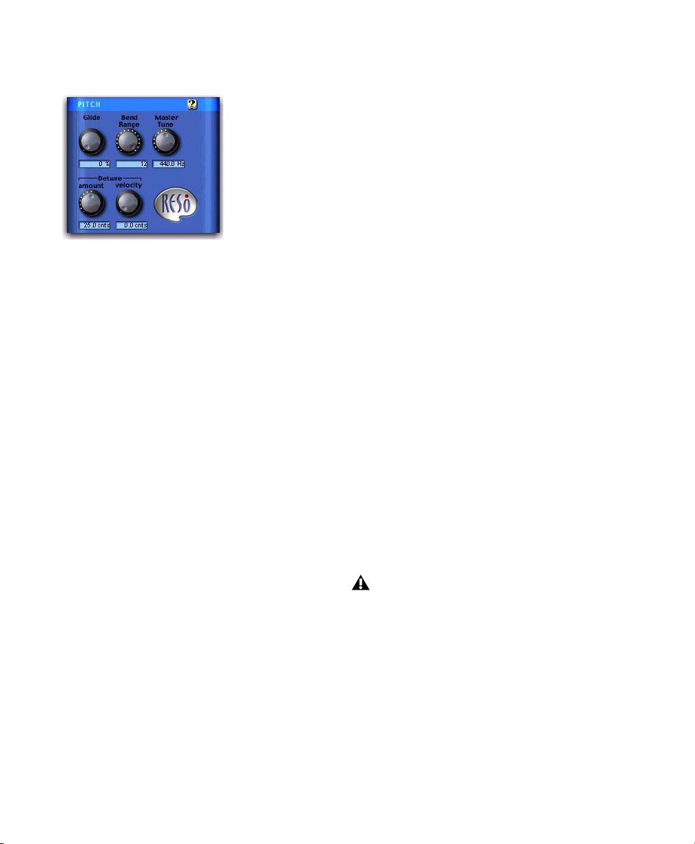
Pitch Controls
Detune Amount
Detuning is a common sound-thickening technique used on synthesizers and many effects devices. Reso’s Detune Amount control lets you set
the maximum amount of pitch detuning that
occurs when multiple voices are stacked together using Voice Stacking. Using a combination of voice stacking and detuning, you can
create timbres that are exceptionally fat.
Pitch controls
Glide
Glide, also known as portamento, determines the
amount of time it takes for a pitch to glide from
the current note to the next note played. This effect is commonly used on synthesizers.
Glide is adjustable from a low of 0.0% (no glide)
to a high of 100% (maximum glide). A setting of
100% will take the longest time to travel from
the current note to the next note played. The effect is also dependant on the interval (distance
of pitch) between the two notes: The larger the
interval, the more noticeable the effect.
Bend Range
Bend Range sets the maximum interval of pitch
bend that can be applied to Reso with a MIDI
controller’s pitch bend wheel. This control is adjustable from 0 semitones (no bend) to 12 semitones (1 octave).
Voices can be detuned up to 50.0 cents. (One
cent is equal to 1/100th of a semitone.)
Detune Velocity
Detune Velocity controls how MIDI key velocity
affects voice detuning. This gives you touch-sensitive control over voice detuning when you
play Reso with a MIDI keyboard.
This control is adjustable from a low of 0.0 cents
(no velocity-sensitive detuning) to a high of
50.0 cents (maximum velocity-sensitive detuning).
If Detune Velocity is set to 0.0 cents, detuning
will not change no matter how hard or soft you
strike a key on your MIDI controller. Conversely, if you set Detune Velocity to 50.0 cents,
a hard strike will detune voices a maximum of
50.0 cents.
Detune Velocity only has an effect when
you play Reso with a velocity-sensitive
MIDI keyboard controller.
Master Tune
Master Tune can be used to tune the pitch of
Reso’s output to another instrument. By default,
this control is set to 440.0 Hz It can be adjusted
from a low of 430.0 Hz to a high of 450.0 Hz.
Digidesign Plug-ins Guide24
Page 31

LPF/Voice Controls
LPF and Voice controls
LPF (Low-Pass Filter)
Reso’s Low-Pass Filter is a single resonant filter
that is applied to all of Reso’s voices.
Frequency
The Frequency control sets the cutoff frequency
of the Low-Pass Filter in Hertz. All frequencies
above the selected cutoff frequency will be attenuated.
The range of this control is from 20 Hz to
20 kHz.
Follower
The Follower is an envelope follower that lets
the filter cutoff frequency dynamically follow
the amplitude of the source audio signal.
The range of this control is from a low of –10 to
a high of +10. With positive values, the louder
the source audio, the higher the cutoff frequency and the wider the filter will open for a
brighter sound. With negative values, the louder
the source audio, the lower the cutoff frequency
and the more the filter will close for a duller
sound.
The effectiveness of the Follower depends on
the filter’s Frequency setting. For example, setting the Follower to +10 and selecting a low Frequency setting will sweep the filter wide on loud
passages. However, if the cutoff frequency is at
its maximum, setting the Follower to +10 will
not sweep the filter at all since it is already completely open.
When used with high Q settings and a relatively
low cutoff frequency, the Follower can be used
to produce an automatic wah-wah-type effect.
Q
Sometimes referred to as resonance on synthesizers, Q adjusts the height of the resonant peak
that occurs at the filter’s cutoff frequency.
Increasing the Q increases the volume of frequencies near the filter’s cutoff frequency (suppressing the more remote frequencies) and adds
a nasal quality to the audio. High Q settings let
you create wah-wah type effects, particularly
when the filter is swept with the Follower.
The range of this control is from 0 to 10.
Mono (Monophonic)
In this mode, Reso responds monophonically,
producing a single note even if more than one is
played simultaneously (though multiple voices
can be stacked on the same note using the Voice
Stacking control). Monophonic mode gives
voice priority to the most recently played note.
Chapter 4: Bruno and Reso 25
Page 32

Poly (Polyphonic)
In this mode, Reso responds polyphonically,
producing as many notes as are played simultaneously (up to 62 on Pro Tools|HD Accel systems). The number of notes that can be played
simultaneously depends on the Voice Stacking
setting chosen. A voice stack setting of 1, for example, allows up to 62 individual notes simultaneously. A voice stack setting of All allows only
one note at a time, but will stack all 62 voices on
that note, producing an extremely fat sound.
Polyphony will be reduced by half at
96 kHz.
In a 44.1 kHz or 48 kHz session on Pro Tools|HD
systems not equipped with an HD Accel card,
the standard Reso module can simultaneously
play up to:
• 28 notes in a 1-voice stack
• 14 notes in a 2-voice stack
• 7 notes in a 4-voice stack
• 3 notes in an 8-voice stack
• 1 note in a 28-voice (All) stack
If all available voices are being used, playing an
additional note will replace the first note played
in the chord.
Voi ce Sta ck
Voice Stack selects the number of voices that are
used, or stacked when you play a single note. The
number of voices that you choose to stack will
directly affect polyphony. Selecting a larger
number of stacked voices will reduce the number of notes that you can play simultaneously.
The sample rate of your session will also affect
polyphony.
Voice Stack
In a 96 kHz session, Reso on Pro Tools|HD Accel
systems can simultaneously play up to:
• 32 notes in a 1-voice stack
• 16 notes in a 2-voice stack
• 4 notes in a 4-voice stack
• 2 notes in an 8-voice stack
• 1 note in an 14-voice (All) stack
Online Help
Online help
To use online help, click the name of any control or parameter and an explanation will appear. Clicking the Online Help button itself provides more details on using this feature.
Digidesign Plug-ins Guide26
Page 33

chapter 5
D-Fi
D-Fi consists of four separate plug-ins for TDM,
RTAS, and AudioSuite. D-Fi plug-ins form a
unique sound design tool kit for processing and
deconstructing audio in several retro and synthesis-oriented ways.
Lo-Fi
Lo-Fi provides retro and down-processing effects, including:
• Bit-rate reduction
• Sample rate reduction
• Soft clipping distortion and saturation
• Anti-aliasing filter
• Variable amplitude noise generator
Lo-Fi can be used as either a real-time TDM or
RTAS plug-in or as a non-real-time AudioSuite
plug-in.
The multichannel TDM version of the Lo-Fi
plug-in is not supported at 192 kHz, use the
multi-mono TDM or RTAS version instead.
Sci-Fi
Sci-Fi provides analog synthesizer-type effects,
including:
• Ring modulation
• Frequency modulation
• Variable-frequency, positive and negative
resonator
• Modulation control by LFO, envelope follower, sample-and-hold, or trigger-andhold
Sci-Fi can be used as either a real-time TDM or
RTAS plug-in or as a non-real-time AudioSuite
plug-in.
The multichannel TDM version of the
Sci-Fi plug-in is not supported at 192 kHz.
Use the multi-mono TDM or RTAS version
instead.
Chapter 5: D-Fi 27
Page 34

Recti-Fi
Purposely Degrading Audio
Recti-Fi provides additive harmonic processing
effects through waveform rectification, and includes:
• Subharmonic synthesizer
• Full wave rectifier
• Pre-filter for adjusting effect frequency
• Post-filter for smoothing generated waveforms
Recti-Fi can be used as either a real-time TDM or
RTAS plug-in or as a non-real-time AudioSuite
plug-in.
Vari-Fi
Vari-Fi provides a pitch-change effect similar to
a tape deck or record turntable speeding up from
or slowing down to a complete stop. Features include:
• Speed up from a complete stop to normal
speed
• Slow down to a complete stop from normal
speed
Contemporary music styles, especially hip-hop,
make extensive use of retro instruments and
processors such as vintage drum machines, samplers, and analog synthesizers. The low bit-rate
resolutions and analog “grunge” of these devices are an essential and much-desired part of
their sonic signatures. That is why Digidesign
created D-Fi.
The D-Fi suite of plug-ins combines the best of
these instruments of the past with the flexibility
and reliability of the Pro Tools audio production
system. The result is a set of sound design tools
that let you create these retro sounds without
the trouble and expense of resampling audio
through 8-bit samplers or processing it through
analog synthesizers.
Lo-Fi
Lo-Fi down-processes audio by reducing its sample rate and bit resolution. It is ideal for emulating the grungy quality of 8-bit samplers.
Vari-Fi is an AudioSuite plug-in only.
Digidesign Plug-ins Guide28
Lo-Fi
Page 35

Lo-Fi Controls
Sample Rate
The Sample Rate slider adjusts an audio file’s
playback sample rate in fixed intervals from
700 Hz to 33 kHz in sessions with sample rates
of 44.1 kHz, 88.2 kHz, or 176.4 kHz; and from
731 Hz to 36 kHz in sessions with sample rates
of 48 kHz, 96 kHz, or 192 kHz. Reducing the
sample rate of an audio file has the effect of degrading its audio quality. The lower the sample
rate, the grungier the audio quality.
The maximum value of the Sample Rate control
is Off (which effectively means bypass).
The range of the Sample Rate control is
slightly different at different session sample
rates because Lo-Fi’s subsampling is calculated by integer ratios of the session sample
rate.
Anti-Alias Filter
The Anti-Alias filter works in conjunction with
the Sample Rate control. As you reduce the sample rate, aliasing artifacts are produced in the audio. These produce a characteristically dirty
sound. Lo-Fi’s anti-alias filter has a default setting of 100%, automatically removing all aliasing artifacts as the sample rate is lowered.
This control is adjustable from 0% to 100%, letting you add precisely the amount of aliasing
you want back into the mix. This slider only has
an effect if you have reduced the sample rate
with the Sample Rate control.
Sample Size
The Sample Size slider controls the bit resolution of the audio. Like sample rate, bit resolution affects audio quality and clarity. The lower
the bit resolution, the grungier the quality. The
range of this control is from 24 bits to 2 bits.
Quantization
Lo-Fi applies quantization to impose the selected bit size on the target audio signal. The
type of quantization performed can also affect
the character of an audio signal. Lo-Fi provides
you with a choice of linear or adaptive quantization.
Linear Linear quantization abruptly cuts off
sample data bits in an effort to fit the audio into
the selected bit resolution. This imparts a characteristically raunchy sound to the audio that
becomes more pronounced as the sample size is
reduced. At extreme low bit-resolution settings,
linear quantization will actually cause abrupt
cut-offs in the signal itself, similar to gating.
Thus, linear resolution can be used creatively to
add random percussive, rhythmic effects to the
audio signal when it falls to lower levels, and a
grungy quality as the audio reaches mid-levels.
Adaptive Adaptive quantization reduces bit
depth by adapting to changes in level by tracking and shifting the amplitude range of the signal. This shifting causes the signal to fit into the
lower bit range. The result is a higher apparent
bit resolution with a raunchiness that differs
from the harsher quantization scheme used in
linear resolution.
Noise Generator
The Noise slider mixes a percentage of pseudowhite noise into the audio signal. Noise is useful
for adding grit into a signal, especially when you
are processing percussive sounds. This noise is
shaped by the envelope of the input signal. The
range of this control is from 0 to 100%. When
noise is set to 100%, the original signal and the
noise are equal in level.
Chapter 5: D-Fi 29
Page 36

Distortion/Saturation
The Distortion and Saturation sliders provide
signal clipping control. The Distortion slider determines the amount of gain applied and lets
clipping occur in a smooth, rounded manner.
The Saturation slider determines the amount of
saturation added to the signal. This simulates
the effect of tube saturation with a roll-off of
high frequencies.
Fans of Spinal Tap will be pleased to know that
the Distortion and Saturation controls can be set
to eleven for maximum effect.
Sci-Fi Controls
Input Level
Input Level attenuates signal input level to the
Sci-Fi processor. Since some of Sci-Fi’s controls
(such as the Resonator) can cause extreme
changes in signal level, the Input Level is particularly useful for achieving unity gain with the
original signal level. The range of this control is
from –12dB to 0dB.
Effect Type
Sci-Fi provides four different types of effects:
Output Meter
The Output Meter indicates the output level of
the processed signal. Note that this meter indicates the output level of the signal—not the input level. If this meter clips, the signal may have
clipped on input before it reached Lo-Fi. Monitor your send or insert signal levels closely to
prevent this from happening.
Sci-Fi
Sci-Fi is designed to mock-synthesize audio by
adding effects such as ring modulation, resonation, and sample & hold, that are typically
found on older, modular analog synthesizers.
Sci-Fi is ideal for adding a synth edge to a track.
Sci-Fi
Ring Mod The Ring Modulator modulates the
signal amplitude with a carrier frequency, producing harmonic sidebands that are the sum
and difference of the frequencies of the two signals. The carrier frequency is supplied by Sci-Fi
itself. The modulation frequency is determined
by the Effect Frequency control. Ring modulation adds a characteristic hard-edged, metallic
sound to audio.
Freak Mod Freak Mod is a frequency modulation
processor that modulates the signal frequency
with a carrier frequency, producing harmonic
sidebands that are the sum and difference of the
input signal frequency and whole number multiples of the carrier frequency. Frequency modulation produces many more sideband frequencies than ring modulation and an even wilder
metallic characteristic. The Effect Frequency determines the modulation frequency of the Freak
Mod effect.
Resonator+ and Resonator– Resonator+ and Resonator– add a resonant frequency tone to the
audio signal. This frequency is determined by
the Effect Frequency. The difference between
these two modules is that Resonator– reverses
the phase (polarity) of the effect, producing a
Digidesign Plug-ins Guide30
Page 37

hollower sound than Resonator+. The Resonator
can be used to produce metallic and flanging effects that emulate the sound of classic analog
flangers.
Effect Amount
Effect Amount controls the mix of the processed
sound with the original signal. The range of this
control is from 0–100%.
Effect Frequency
Effect Frequency controls the modulation frequency of the ring modulator and resonators.
The frequency range is dependent on the effect
type. For the Ring Modulator, the frequency
range of this control is from 0 Hz to 22.05 kHz.
For Freak Mod, the frequency range is from 0 Hz
to 22.05 kHz. For Resonator+, the frequency
range is from 344 to 11.025 kHz. For Resonator–,
the frequency range is from 172 Hz to 5.5 kHz.
You can also enter a frequency value using keyboard note entry.
To use keyboard note entry:
1 Windows-click (Windows) or Control-click
(Mac) the Effect Frequency slider to display the
pop-up keyboard.
2 Select the note on the keyboard that you want
for the Effect Frequency.
Modulation Type
Modulation Type determines the type of modulation applied to the frequency of the selected
effect. Depending on the type of modulation
you select here, the sliders below it will change
to provide the appropriate type of modulation
controls. If the Mod Amount is set to 0%, no dynamic modulation is applied to the audio signal.
The Effect Frequency slider then becomes the
primary control for modifying the sound.
LFO Produces a low-frequency triangle wave as a
modulation source. The rate and amplitude of
the triangle wave are determined by the Mod
Rate and Mod Amount controls, respectively.
Envelope Follower Causes the selected effect to
dynamically track the input signal by varying
with the amplitude envelope of the audio signal. As the signal gets louder, more modulation
occurs. This can be used to produce a very good
automatic wah-wah-type effect. When you select the Envelope Follower, the Mod Amount
slider changes to a Mod Slewing control. Slewing provides you with the ability to smooth out
extreme dynamic changes in your modulation
source. This provides a smoother, more continuous modulation effect. The more slewing you
add, the more gradual the changes in modulation will be.
Sample+Hold Periodically samples a random
pseudo-noise signal and applies it to the effect
frequency. Sample and hold modulation produces a characteristic random stair-step modulation. The sampling rate and the amplitude are
determined by the Mod Rate and Mod Amount
controls, respectively.
Sci-Fi Keyboard Note Entry
Trigger+Hold Trigger and Hold modulation is
similar to Sample and Hold modulation, with
one significant difference: If the input signal
falls below the threshold set with the Mod
Threshold control, modulation will not occur.
Chapter 5: D-Fi 31
Page 38

This provides interesting rhythmic effects,
where modulation occurs primarily on signal
peaks. Modulation will occur in a periodic, yet
random way that varies directly with peaks in
the audio material. Think of this type of modulation as having the best elements of both Sample and Hold and the Envelope Follower.
Mod Amount and Mod Rate
These two sliders control the amplitude and frequency of the modulating signal. The modulation amount ranges from 0% to 100%. The modulation rate, when LFO or Sample and Hold are
selected, ranges from 0.1 Hz to 20 Hz.
Recti-Fi
Recti-Fi provides additive synthesis effects
through waveform rectification. Recti-Fi multiplies the harmonic content of an audio track
and adds subharmonic or superharmonic tones.
If you select Trigger and Hold as a modulation
type, the Mod Rate slider changes to a Mod
Threshold slider, which is adjustable from
–95 dB to 0 dB. It determines the level above
which modulation occurs with the Trigger and
Hold function.
If you select Envelope Follower as a modulation
type, the Mod Rate slider changes to a Mod
Slewing slider, which is adjustable from 0% to
100%.
Output Meter
The Output Meter indicates the output level of
the processed signal. Note that this meter indicates the output level of the signal—not the input level. If this meter clips, the signal may have
clipped on input before it reached Sci-Fi. Monitor your send or insert signal levels closely to
prevent this from happening.
Recti-Fi
Recti-Fi Controls
Pre-Filter
The Pre-Filter filters out high frequencies in an
audio signal prior to rectification. This is desirable because the rectification process can cause
instability in waveform output—particularly in
the case of high-frequency audio signals. Filtering out these higher frequencies prior to rectification can improve waveform stability and the
quality of the rectification effect. If you wish to
create classic subharmonic synthesis effects, set
the Pre-Filter and Post-Filter to a relatively low
frequency, such as 250 Hz.
The range of the Pre-Filter is from 43 Hz to
21 kHz, with a maximum value of Thru (which
effectively means bypass).
Digidesign Plug-ins Guide32
Page 39

Normal waveform
Rectification
Positive Rectification
This rectifies the waveform so that its phase is
100% positive. The audible effect is a doubling
of the audio signal’s frequency.
Positive rectification
Negative Rectification
Alternating Rectification
This alternates between rectifying the phase of
the first negative waveform excursion to positive, then the next positive excursion to negative, and so on, throughout the waveform. The
audible effect is a halving of the audio signal’s
frequency, creating a subharmonic tone.
Alternating rectification
Alt-Max Rectification
This alternates between holding the maximum
value of the first positive excursion through the
negative excursion period, switching to rectify
the next positive excursion, and holding its
peak negative value until the next zero crossing.
The audible effect is a halving of the audio signal’s frequency, and creating a subharmonic
tone with a hollow, square wave-like timbre.
This rectifies the waveform so that its phase is
100% negative. The audible effect is a doubling
of the audio signal’s frequency.
Negative rectification
Alt-Max rectification
Chapter 5: D-Fi 33
Page 40

Gain
Gain lets you adjust signal level before the audio
reaches the Post-Filter. This is particularly useful
for restoring unity gain if you have used the PreFilter to cut off high frequencies prior to rectification. The range of this control is from –18dB
to +18dB.
Post-Filter
Waveform rectification, particularly alternating
rectification, typically produces a great number
of harmonics. The Post Filter lets you remove
harmonics above the cutoff frequency and
smooth out the sound. This Post-Filter is useful
for filtering audio that contains subharmonics.
To create classic subharmonic synthesis effects,
set the Pre-Filter and Post-Filter to a relatively
low frequency.
The range of the Post-Filter is 43 Hz to 21 kHz,
with a maximum value of Thru (which effectively means bypass).
Mix
Mix adjusts the mix of the rectified waveform
with the original, unprocessed waveform.
Output Meter
The Output Meter indicates the output level of
the processed signal. Note that this meter indicates the output level of the signal—not the input level. If this meter clips, the signal may have
clipped on input before it reached Recti-Fi. Monitor your send or insert signal levels closely to
prevent this from happening.
Vari-F i
(AudioSuite Only)
Vari-Fi is an AudioSuite-only plug-in that provides a pitch-change effect similar to a tape deck
or record turntable speeding up from or slowing
down to a complete stop. Vari-Fi preserves the
original duration of the audio selection.
Vari-F i
Vari-Fi Controls
Speed Up
Speed Up applies a pitch-change effect to the selected audio, similar to a tape recorder or record
turntable speeding up from a complete stop.
The effect doesn’t change the duration of the
audio selection.
Slow Down
Slow Down applies a pitch-change effect to the
selected audio, similar to a tape recorder or
record turntable slowing down to a complete
stop. The effect doesn’t change the duration of
the audio selection.
Digidesign Plug-ins Guide34
Page 41

D-Fi Demo Session
D-Fi includes a demo session that illustrates
some of the effects you can produce with Lo-Fi,
Sci-Fi, and Recti-Fi.
The D-Fi demo session contains drum, bass, and
guitar loops. Memory locations let you quickly
locate a particular loop and apply different D-Fi
effects.
Before you begin:
1 Open the demo session.
2 Choose Windows > Show Memory Locations.
Hi-Hat Loop
1 Click memory location #1, “Hat Loop.”
2 Click the Sci-Fi insert on the Master Fader to
display Sci-Fi.
3 Press the Spacebar to audition the Hi-Hat
loop. Since the Bypass button is enabled, you
will hear the loop without Sci-Fi processing.
4 Press the Spacebar to stop the Hi-Hat loop.
5 Choose “Res-1/4 note Trig. & Hold.”
6 Deselect the Bypass button to hear the effect.
7 Press the Spacebar to audition the Hi-Hat
loop.
Sci-Fi Examples
The following examples demonstrate Sci-Fi. Follow the instructions in each section below to
hear useful applications for this plug-in.
Choosing a Sci-Fi setting
8 Listen to the effect. Note how Trigger and
Hold is used to cause modulation to follow the
amplitude. This provides a much more interesting type of modulation than standard envelope
following.
9 Adjust the Mod Threshold to vary the modu-
lation on 1/4 note accents.
10 Choose “Res. –16 note Trig & Hold.” This set-
ting demonstrates a similar type of modulation
that occurs on 16th notes.
11 Choose “Wah Res-LFO Faux Flange.” This
setting demonstrates a basic flanging-type effect. Try changing the Rate control and switching to the Resonator+. Experiment with the Mod
Type for interesting effects.
Chapter 5: D-Fi 35
Page 42

Drum Kit Loop
1 Click memory location #2, “Drum Kit Loop.”
2 Select Bypass to hear the Drum Kit loop with-
out Sci-Fi processing.
Lo-Fi Examples
The examples that follow demonstrate Lo-Fi.
Follow the instructions in each section below to
hear useful applications for this plug-in.
3 Choose “Ring Mod Trig & Hold Kit.”
4 Deselect Bypass to hear the effect.
5 Press the Spacebar to audition the Drum Kit
loop. This setting uses ring modulation, and
trigger and hold for modulation that changes
only on audio peaks.
6 Choose “Res-Env. Follower.” This setting dem-
onstrates the use of the Envelope Follower to
create resonant flanging that modulates and
matches the dynamics of the source audio.
7 Choose “Freq. Mod Env. F. Kit.” This setting
demonstrates frequency modulation.
8 Experiment with the other settings.
9 Finally, click memory location #4,
“Bass/Drums Loop.” Try each of the Sci-Fi settings with this loop.
Wah Guitar Loop
1 Click memory location #3, “Wah Guitar
Loop.”
2 Select Bypass to hear this loop without Sci-Fi
processing.
3 Choose “Freq Mod Env. Follower Wah.”
4 Deselect Bypass to hear the effect.
5 Press the Spacebar to audition this loop.
6 Try each of the Sci-Fi settings with this loop.
Before you begin:
1 Open the demo session.
2 Choose Windows > Show Memory Locations.
3 Select Bypass in the Sci-Fi Plug-in window to
take it out of the mix.
4 Click the Lo-Fi insert on the master fader to
display Lo-Fi.
Choosing a Lo-Fi setting
Slam Kit Loop
1 Open the Lo-Fi Plug-in window.
2 Click memory location #7, “Slam Kit Loop.”
3 Select Bypass to hear the loop without Lo-Fi
processing.
4 Press the Spacebar to audition the loop.
5 Deselect Bypass to hear the effect.
6 Try each Lo-Fi setting with this loop.
Digidesign Plug-ins Guide36
Page 43

The loop has a hip-hop feel, and demonstrates
how Lo-Fi can be used to create textures with
hard percussive elements.
Drum Kit Loop
1 Click memory location #2, “Drum Kit Loop.”
2 Choose “Lo-rate Distorto Kit.”
3 Experiment with the Sample Rate, Saturation,
and Distortion controls to vary the results.
This loop demonstrates how Lo-Fi can be used to
create grungy drums.
Bass Only
1 Click memory location #6, “Bass Only.”
2 Choose “Bass Dirty Amp.”
3 Use the Bypass button to compare the sound
of the processed and unprocessed bass.
This setting simulates a gritty bass amp with
limited high-end. Adjust the Saturation and Distortion controls to experiment with the distortion effect.
Recti-Fi Examples
The examples that follow demonstrate Recti-Fi.
Follow the instructions in each section below to
hear useful applications for this plug-in.
Before you begin:
1 Open the demo session.
2 Choose Windows > Show Memory Locations.
3 Select Bypass in the Sci-Fi Plug-in window to
take it out of the mix.
4 In the Mix window, select Recti-Fi in the place
of Lo-Fi on the Master Fader.
4 Choose “Trash Bass.”
This setting demonstrates an unusual distortion
effect. Experiment with bit depth to hear how it
affects audio quality.
5 Choose “Ring Moddy Bass.”
This setting demonstrates extreme Lo-Fi processing.
Choosing a Recti-Fi setting
Sub Octave Bass
1 Click memory location #6, “Bass Only.”
2 Choose “Sub Octave Bass.”
In this setting, the Pre-Filter and Post-Filter are
optimized for octave-doubling beneath the bass.
Sub-Oct. Heavy Bass
Choose “Sub-Oct. Heavy Bass.”
This setting uses Alt-Max rectification to provide
more bottom end. Try experimenting with the
Mix control and other controls.
Chapter 5: D-Fi 37
Page 44

Drum Kit Loop
1 Click memory location #2, “Drum Kit Loop.”
Wah Guita r
1 Click memory location #3, “Wah Guitar.”
2 Choose “Sub Kit.”
3 Compare the sound of the processed and un-
processed audio using the Bypass button.
This setting demonstrates how to use sub-octave
rectification to enhance low frequencies.
Hat Loop
1 Click memory location #1, “Hat Loop.”
2 Choose “Noise Hat.”
3 Compare the sound of the processed and un-
processed audio using the Bypass button.
This setting demonstrates how Recti-Fi can produce a periodic noise version of the hi-hat signal
that varies with the original audio.
4 Adjust the Mix control to hear the signal fully
wet.
5 Adjust the Pre-Filter during playback and lis-
ten to the results. Automating changes in the
Pre-Filter frequency can produce useful effects.
2 Choose “Up Octave Wah.”
3 Play the audio.
This setting produces a signal that is an octave
higher than the original and adds some interesting audio artifacts.
4 Experiment with the Mix control, Pre-Filter,
and Post-Filter then listen to the results.
Slam Kit Loop
1 Click memory location #7, “Slam Kit Loop.”
2 Choose “Trasho Kit.”
3 Play the audio.
This setting illustrates the use of Recti-Fi as a basic sound modifier for percussive sounds.
Digidesign Plug-ins Guide38
Page 45

chapter 6
DINR
Digidesign Intelligent Noise Reduction™
(DINR) provides Broadband Noise Reduction
(BNR).
Provides broadband and narrowband noise reduction for suppressing such unwanted elements as tape hiss, air conditioner rumble, and
microphone preamp noise. BNR is available as a
real-time TDM plug-in, and as an AudioSuite
plug-in.
DINR LE (available with Pro Tools LE with
DV Toolkit™ 2 and Pro Tools LE or Pro Tools
M-Powered with Music Production Toolkit only)
provides RTAS and AudioSuite versions of the
BNR.
The TDM version of Broadband Noise Reduction is not supported at sample rates
above 96 kHz. The AudioSuite version of
Broadband Noise Reduction supports
192 kHz.
Broadband Noise Reduction
The Broadband Noise Reduction module (BNR)
removes many types of broadband and narrowband noise from audio material. It is best suited
to reducing noise whose overall character
doesn’t change very much: tape hiss, air conditioner rumble, and microphone preamp noise.
In cases where recorded material contains several types of noise, the audio can be processed
repeatedly according to the specific types of
noise.
BNR TDM
Chapter 6: DINR 39
Page 46

How Broadband Noise Reduction Works
The Broadband Noise Reduction module uses a
proprietary technique called Dynamic Audio Sig-
nal Modeling
from the digital audio file. Noise is removed
with multiple downward expanders that linearly decrease the gain of a signal as its level
falls.
™
to intelligently subtract the noise
The Contour Line
Once the signal level has fallen below the specified Contour Line (which represents BNR’s
threshold), the downward expanders are activated and decrease the gain of the signal as its
level falls. Over five hundred individual downward expanders are used linearly across the audio spectrum to reduce the effects of unwanted
noise.
Creating a Noise Signature
The first step in performing broadband noise reduction is to create what is called a noise signa-
ture by selecting and analyzing an example of
the noise within the source material. Using this
noise signature, a noise contour line is created
which is used to define the thresholds for the
downward expanders that will perform the
broadband noise reduction. The noise contour
represents an editable division between the
noise and non-noise audio signals.
At the same time, DINR also creates a model of
what the non-noise audio signal looks like.
DINR then attempts to pull apart these two
models, separating the bad from the good—the
noise from the desired audio. The noise portion
can then be reduced or eliminated.
The noise reduction itself is achieved through
the use of multiple downward expanders. The
threshold of these expanders is set so that the
noise signal will fall below them and be decreased while the desired audio signal will remain above them, untouched.
Psychoacoustic Effects of Noise Reduction
One of the psychoacoustic effects associated
with broadband noise reduction is that listeners
often perceive the loss of noise as a loss of high
frequencies. This occurs because the noise in the
higher frequency ranges fools the ear into thinking the original signal has a great deal of energy
in that range. Consequently, when the noise is
removed it feels as if there has been a loss of
high-frequency signal. DINR’s High-Shelf EQ is
useful for compensating for this effect. See
“High-Shelf EQ” on page 43.
Limitations of Noise Reduction
It is important to understand that there is a certain amount of trade-off inherent in any type of
noise reduction system. Implementing noise reduction means that you have to choose the best
balance between the following three things:
The amount of noise removed from the signal
The amount of signal removed from the signal
The number of artifacts added to the signal
Digidesign Plug-ins Guide40
Page 47

DINR gives you a considerable amount of control over the above three elements, and lets you
maximize noise reduction while minimizing signal loss and artifact generation. However, as
powerful as it is, DINR does have limitations. In
particular, there are two instances in which
DINR may not yield significant results:
Cases in which the noise components of the
audio are so prominent that they obscure the actual signal components of the audio.
Cases in which the noise amplitude of a 24-bit
file is less than –96 dB. DINR is not designed to
recognize noise that is lower than this level.
Broadband Noise Reduction Controls
The following section describes the Broadband
Noise Reduction controls and their use.
Spectral Graph
The Spectral Graph Displays the noise signature
and the editable noise Contour Line. The Spectral Graph’s horizontal axis shows frequency,
which is displayed in Hertz, from 0 Hz to onehalf the current audio file’s sample rate. The
Spectral Graph’s vertical axis shows amplitude,
which is displayed in dB, from 0 dB to –144 dB
(below full-scale output of the audio).
The Noise Signature The jagged line is a graph of
noise. This is called a noise signature. It is created when you use the Learn button in the
Broadband Noise Reduction window. Once you
have the noise signature of an audio file, you
will be able to begin removing the noise by generating and editing a threshold or Contour Line
(covered next) between the noise and the desired audio signal.
Contour Line
The Contour Line The line with a series of square
breakpoints is called the noise contour line. The
Contour Line is an editable envelope which represents the division between the noise and the
non-noise signal in the current audio file. The
Contour Line is created by clicking the Fit or AutoFit button in the Broadband Noise Reduction
window after you have learned a section of
noise. By moving this envelope up or down, or
by moving the individual breakpoints, you can
modify which signals are removed and which
remain.
The noise modeling process treats audio below
the line as mostly noise, and audio above the
line as mostly signal. Therefore, the higher you
move the Contour Line upwards, the more audio is removed. To maximize noise reduction
and minimize signal loss, the Contour Line
should be above any noise components, but below any signal components.
To fine-tune the broadband noise reduction,
move breakpoints at different locations along
this line to find out which segments remove the
noise most efficiently. Editing the Contour Line
Chapter 6: DINR 41
Page 48

to follow the noise signature as closely as possible will also help maximize noise reduction and
minimize signal loss. See “Editing the Contour
Line” on page 47.
NR Amount, Response, Release, and Smoothing
Noise Reduction Amount Controls how much
the noise signal is reduced. It is calibrated in
decibels. A setting of 0 dB specifies no noise reduction. Increasing negative amounts specify
more noise reduction. The default value is 0 dB.
In many cases, as much as 20–30 dB of noise reduction can be used to good effect. However, because higher amounts of noise reduction can
generate unwanted audio artifacts, you may
want to avoid setting the NR Amount slider to
its maximum value.
Response Adjusts how quickly the downward
expanders and noise reduction process responds
to the overall changes in the noise in milliseconds. Depending on the character of the noise,
different settings of this control will produce
varying amounts of artifacts in the signal, as the
modeling process attempts to track the noise
signal faster or slower.
The Response speed ranges from 0 ms to 116 ms.
A setting of 116 ms (slow) specifies that the
modeling process should not attempt to track
very fast changes in the noise character. A setting of 0 ms (fast) specifies that the modeling
process should attempt to follow every change
in the noise character very closely.
A faster setting can yield more noise removal,
but it may generate more artifacts. This is similar
to how a noise gate produces chatter when attempting to track highly dynamic material. A
slower setting will allow slightly less noise removal, but will generate much fewer artifacts.
Release Use in conjunction with the Response
slider. It controls how quickly DINR reduces the
amount of noise reduction when the amount of
noise present in the audio diminishes. Release
times range from 0 ms to 116 ms. Like the Response control, a faster setting can yield more
noise removal, but it may also generate artifacts.
You may want to avoid setting this control to its
slowest position, since it will cause the noise
tracking to slow to the point that the other controls seem to have no effect.
Smoothing Controls the rate at which noise reduction occurs once the threshold is crossed. It
lets you reduce the audibility of any artifacts
generated in the modeling process, at the expense of noise reduction accuracy. This is done
by limiting the rate of change of the Response
and Release controls to the specified Smoothing
setting. As soon as the frequency threshold is
reached, the full NR amount value is immediately applied according to Response and Release
settings. When the frequency threshold is
reached, DINR will ramp to the NR Amount
level. Settings range from 0 to 100%. A setting of
0% specifies no smoothing. A setting of 100%
specifies maximum smoothing.
Digidesign Plug-ins Guide42
Page 49

High-Shelf EQ
The High-Shelf EQ (Hi Shelf) is a noiseless filter
that can be applied after noise reduction has
been performed in order to compensate for a
perceived loss of high-frequency content. It is
unique because it operates only on the signal,
not on any remaining noise. The Freq slider controls the center frequency of the filter. Values
range from 20 Hz to 22 kHz.
High-Shelf EQ
The Gain slider controls the gain of the filter.
Values range from –12 dB to +6 dB. The HighShelf EQ can be enabled and disabled by clicking
the Enable button.
You can also use the High-Shelf EQ to reduce the
amount of high frequencies in a signal. This is
particularly useful if you are working with older
recordings that are band-limited, since the highfrequency content in these is probably made up
of noise and not signal.
Learn
Learn
Clicking the Learn button creates a noise signature based on the audio segment currently selected on screen. There are two Learn modes:
Learn First Audio mode and Learn Last Audio
mode.
Learn First Audio Mode Learn First Audio mode
is the default Learn mode. It is designed for use
with audio that has an identifiable noise-only
section that you can locate and pre-select. To
use this mode, locate and select the noise-only
portion of the audio, click the Learn button,
start playback, and BNR will build a noise signature based on the first 16 milliseconds of audio
playback. First Audio Learn mode can be
thought of as a trigger-learn mode, since noise
capturing is triggered by the first audio that
DINR receives.
Learn Last Audio Mode Learn Last Audio mode is
designed to let you locate and identify a segment of noise on-the-fly as you listen to audio
playback. In this mode, you first Alt-click (Windows) or Option-click (Mac) the Learn button,
then initiate audio playback. When you hear
the portion of audio that contains the noise you
want to identify and remove, click the Learn
button a second time. BNR will build a noise signature based on the last 16 milliseconds of audio playback. The Spectral Graph displays data
in real-time in Learn Last Audio mode.
Fit
Fit
The Fit button computes a noise Contour Line
with approximately 30 breakpoints to fit the
shape of the current noise signature. The Contour Line can then be edited to more closely fit
the noise signature or to reduce specific frequency bands by dragging, adding or deleting
breakpoints.
Pressing the Up Arrow or Down Arrow keys on
your computer keyboard lets you raise or lower
the entire Contour Line, or a selected portion of
the Contour Line. The Left/Right arrows lets you
move a selection left or right. To select a portion
of the Contour Line with multiple breakpoints,
Control-drag (Windows) or Command-drag
(Mac) to highlight the desired area.
Chapter 6: DINR 43
Page 50

After you use the Fit function, BNR will automatically boost the entire Contour Line 6 dB
above the noise signature so that all noise components of the audio file are below the Contour
Line. You may want to adjust the Contour Line
downwards as needed to modify the character of
the noise reduction.
Super Fit
Super Fit
The Super Fit button creates a noise Contour
Line consisting of over five hundred breakpoints
in order to follow the shape of the noise signature more precisely.
Scroll Left/Right
Scroll Left/Right
These buttons scroll the Spectral Graph to the
left or right, respectively.
To scroll the Spectral Graph (Mac only), use
Control-Option-Left Arrow or Control-Option-Right Arrow.
Zoom Out/In
Zoom Out/In
Auto Fit
Auto F it
The Auto Fit function is designed to generate a
noise curve for audio that lacks a noise-only portion for DINR to learn. Clicking Auto Fit computes this generic noise curve based on the
points contained within the currently selected
audio, then fits the Contour Line to it. To use
the Auto Fit function, you must first make a selection in the Spectral Graph by Control-dragging (Windows) or Command-dragging (Mac).
If the selected audio has both noise and desired
sound components, you can generate an approximate noise-only Contour Line by selecting
a frequency range that appears to be mostly
noise, then pressing the auto fit button. You can
then edit the resulting noise Contour Line to optimize the noise reduction.
Clicking on these buttons zooms in or out of the
Spectral Graph. This lets you view and edit the
noise contour with greater precision. If you have
selected a breakpoint or breakpoints, press
Alt+Start+Plus (Windows) or Control+Option+Plus (Mac) to zoom the beginning of the
selection to the center of the screen. Press
Alt+Start+Minus (Windows) or Control+Option+Minus (Mac) to zoom back out.
Move Breakpoints Up/Down/Left/Right
Move Breakpoints Up/Down/Left/Right
These arrows behave differently depending on
whether or not there is a selection of points
along the Contour Line.
No Selection: When there is no selection, the Up
and Down arrows move the entire Contour Line
up or down by 1 dB, respectively, and the Left
and Right arrows scroll the display left and right.
Digidesign Plug-ins Guide44
Page 51

With a Selection: Clicking these buttons moves
a selected breakpoint or breakpoints up, down,
right, or left. If there is currently a selection in
the Spectral Graph, clicking the left and right arrow buttons will move the selected breakpoints
left or right. The Up and Down arrows will move
the selected breakpoints up or down, respectively. Alt-Start key-clicking (Windows) or Control-Option-clicking (Mac) the Arrow keys on
your computer keyboard performs the same
function.
Undo
Undo
Clicking the Undo button undoes the last edit to
the Spectral Graph Display. The Undo button
does not undo changes made to slider positions.
Using Broadband Noise Reduction
Before you start using BNR, take a moment to
think about the nature of the noise in your session and where it’s located: Is it on a single track,
or several tracks? Is it a single type of noise, or
several different types? The answers to these
questions will affect how you use BNR.
If there is a single type of broadband noise on a
single track, insert the BNR plug-in onto the
track. Solo the track to make it easier hear as you
remove the noise. If a single track contains different types of noise, you may need to use more
than one DINR insert to remove the other types
of noise. If multiple tracks contain the same
noise, you may want to bus them all to an Auxiliary Input so you can use a single DINR plug-in
insert. This will minimize the amount of DSP
you use.
To use Broadband Noise Reduction:
1 From the Insert pop-up on the track with the
noise, select BNR. The Broadband Noise Reduction window appears.
2 In the Edit window, select the noisiest portion
of the track—ideally, a segment with as little of
the desired signal as possible. This will make it
easier for BNR to accurately model the noise. If
the track contains a segment comprised of noise
only, select that portion.
3 Do one of the following:
• Start audio playback, and in the Broadband
Noise Reduction window, click the Learn
button. BNR samples the first 16 milliseconds of the selected audio and creates its
noise signature.
– or –
• Locate and identify noise on the fly, during
playback, using BNR’s Learn Last Audio
mode. To do this, Alt-click (Windows) or
Option-click (Mac) the Learn button. Begin
playback, and when you hear the segment
that you want DINR to sample as noise,
click Learn a second time. BNR will build a
noise signature based on the 16 milliseconds of audio immediately preceding the
second click.
4 Click Fit. BNR will fit a Contour Line to the
noise signature just created. If you want to create a Contour Line that follows the noise signature even more precisely, click the Super Fit
button. A Contour Line with five hundred
breakpoints is created.
5 To audition the effects of the noise reduction
interactively, in the Edit window, select a portion of audio containing the noise. Then select
Loop Playback from Pro Tools’ Options menu
and press the Spacebar to begin looped audio
playback.
Chapter 6: DINR 45
Page 52

6 Adjust the NR amount slider to reduce the
noise by the desired amount. To compare the
audio with and without noise reduction, click
the Bypass button.
7 To fine-tune the effects of the noise reduction,
adjust the Response, Release, and Smoothing
sliders to achieve optimal results.
8 To further increase noise reduction, edit the
Contour Line. The quickest way to do this is to
move the entire Contour Line upwards. In the
Spectral Graph, Control-drag (Windows) or
Command-drag (Mac) to select the entire waveform range. Then click the Move Breakpoint Up
button. The higher you move the Contour Line
above the noise signature, the more noise is removed. See “Editing the Contour Line” on
page 47.
9 If you feel that some of high end frequencies
of the audio have been lost due to the noise reduction process, try using the High-Shelf EQ to
compensate. To do this, click BNR’s Hi Shelf button and adjust the frequency and gain sliders
until you are satisfied with the results.
If you are happy with the results of the noise reduction, use the Settings and Librarian menus to
save the settings so that you can use them again
in similar sessions.
To enable Learn Last Audio mode, Alt-click
(Windows) or Option-click (Mac) the Learn
button. This button flashes red when armed
for Learn Last Audio mode. When you hear
the target noise, click
Learn a second time.
Performing Noise Reduction on Audio that Lacks a Noise-Only Portion
Ideally, audio that you want to perform noise reduction on will have a noise-only portion at the
beginning or end of the recording that DINR
can analyze and learn. Unfortunately this is not
always the case, and in many recordings some
amount of signal is always mixed with the noise.
Obviously, analyzing such audio will produce a
noise signature that is based partially on signal.
Luckily, DINR has provisions for cases such as
this, and this is where the Auto Fit feature comes
in.
If your audio file lacks a noise-only portion for
DINR to analyze, you can still obtain reasonable
results by selecting and learning a segment of
audio that has a relatively low amount of signal
and a high amount of noise (as in a quiet passage). By then selecting a frequency range of the
noise signature and using the Auto Fit function
to generate a generic noise curve, you can recompute the Contour Line based on this selection.
Some editing of the newly generated Contour
Line will probably be necessary to yield optimum results, since it is not based entirely on
noise from your audio file. See “Editing the Contour Line” on page 47.
Digidesign Plug-ins Guide46
Page 53

To generate a Contour Line for audio that lacks a
noise-only portion:
1 In the Edit window, select a segment of audio
with a relatively low amount of signal and a
high amount of noise.
2 Click the Inserts pop-up on the track with the
noise and select BNR. The Broadband Noise Reduction window appears.
Editing the Contour Line
One of the most effective ways to fine-tune the
effects of broadband noise reduction is to edit
the Contour Line. The Contour Line treats audio
below the line as mostly noise, and audio above
the line as mostly signal. Therefore, the higher
your move the Contour Line upwards, the more
audio is removed.
3 Click the Learn button to create a preliminary
noise signature.
4 Click the Fit button to fit a Contour Line to it.
5 In BNR’s Spectral Graph, Control-drag (Win-
dows) or Command-drag (Mac) to make a selection. Select points where the high-frequency
noise components are most evident. In general,
the flatter areas of the Spectral Graph, are better,
since they represent quieter areas where there is
probably less signal and more noise.
6 Click the Auto Fit button. DINR computes a
generic noise curve and corresponding Contour
Line based on your selection. If you want to remove the selection in the Spectral Graph Display, Control-click (Windows) or Commandclick (Mac) once.
7 Follow the steps given in the previous section
removing the noise using the NR Amount slider
and other controls.
8 Since the Contour Line is not based entirely
on noise from your audio file, you may also
want to edit its envelope in order to fine-tune
the noise reduction. See “Editing the Contour
Line” on page 47.
To maximize noise reduction and minimize signal loss, the Contour Line should be above any
noise components, but below any signal components. To fine-tune the broadband noise reduction, try moving individual breakpoints at different locations along this line to find out which
segments remove the noise most efficiently. For
more dramatic results, try moving the entire
Contour Line upwards. One drawback of the latter technique is that it will typically remove a
considerable amount of signal along with the
noise.
Remember that high-frequency noise components are typically more evident in the flatter,
lower amplitude areas of the Spectral Graph. Try
editing the Contour Line in these areas first.
To hear the changes you make to the Contour Line
in real time:
1 Select the target audio in Pro Tools’ Edit win-
dow. Make sure the selection is at least a second
or two in length. If the selection is too short,
you won’t be able to loop playback.
2 Select Options > Loop Playback.
3 Begin playback.
Noise components on the Spectral Graph
Chapter 6: DINR 47
Page 54

To edit the Contour Line:
1 To move a breakpoint, click directly on it and
drag it to the desired position. Moving a breakpoint higher increases noise reduction at that
range. Moving a breakpoint lower decreases
noise reduction at that range.
Dragging a breakpoint
2 To move multiple breakpoints, Control-drag
(Windows) or Command-drag (Mac) to select
the desired breakpoints. Click the appropriate
Move Breakpoint button (below the Spectral
Graph) to move the selected breakpoints in 1 dB
increments. Control-Shift-drag (Windows) or
Command-Shift-drag (Mac) to extend your selection.
4 To create a new breakpoint, click on the Con-
tour Line.
5 To delete a breakpoint, Alt-click (Windows) or
Option-click (Mac) the breakpoint. As long as
you click and hold the mouse, you will delete all
breakpoints that the cursor passes over.
Using BNR AudioSuite
BNR AudioSuite is identical to the real-time version of BNR, with the addition of two features to
enhance the noise reduction process. These features are:
Audition Lets you listen specifically to the noise
portion being removed from the target material.
This makes it easier to fine-tune noise reduction
settings to maximize noise reduction and minimize signal loss.
Post-Processing Applies post-processing to the
audio file to help remove undesirable artifacts
that are a result of noise reduction.
Moving selected breakpoints
3 To move the entire Contour Line, Control-
drag (Windows) or Command-drag (Mac) to select the entire range. Click the appropriate Move
Breakpoint button (below the Spectral Graph) to
move the selected breakpoints in 1 dB increments. The higher you move the Contour Line
above the noise signature, the more noise is removed.
Digidesign Plug-ins Guide48
To enable either of these features, click the corresponding button. To disable them, click again.
BNR AudioSuite
Page 55

To process a region with the BNR AudioSuite
plug-in:
1 Select the desired regions in the target tracks
or the Audio Regions List. Only tracks and regions that are selected will be processed.
2 From the Pro Tools AudioSuite menu, choose
BNR.
3 Click Learn to capture the noise signature of
the selected material. If you have selected more
than one track or region, BNR will build the
noise signature based on the first selected track
or region when used in Mono mode, or the first
two selected track or region when used in Stereo
mode.
4 Click Fit or Super Fit to create a Contour Line
that matches the noise signature.
5 Click Preview to begin playback of the selected
material.
6 Adjust BNR controls and fine-tune the noise
reduction using the techniques explained above
(See “Using Broadband Noise Reduction” on
page 45.)
7 To hear the noise components that are being
removed, click Audition. Adjusting BNR’s controls while toggling this on and off will let you
fine-tune the noise reduction. It also lets you
hear exactly how much signal is being removed
with the noise, and adjust your controls accordingly.
8 If unwanted artifacts are generated by the
noise reduction process, click Post-processing.
For best results, set the Response and Release
controls to zero.
To begin AudioSuite processing:
1 Adjust the AudioSuite File controls. These set-
tings will determine how the file is processed
and what effect the processing will have on the
original regions. Here are some guidelines:
Decide where the selected region should be
processed:
• To process the selected region only in the
track in which it appears, choose Playlist
from the Selection Reference pop-up.
– or –
• To process the selected region in the Audio
Regions List only, choose Region List from
this pop-up.
Decide if you want to update every occurrence
of the selection region:
• To process and update every occurrence of
the selected region throughout your session, enable the Use In Playlist button (and
also choose Region List from the Selection
Reference pop-up).
– or –
• If you do not want to update every occurrence of the selected region, disable the Use
In Playlist button.
If you have selected multiple regions for pro-
cessing and want to create a new file that connects and consolidates all of these regions
together, choose Create Continuous File from
the File mode pop-up menu.
BNR AudioSuite does not allow destructive
processing, so the Overwrite Files option is
not available in the File mode pop-up
menu.
2 From the Destination Track pop-up, choose
the destination for the replacement audio.
3 Click Process.
Chapter 6: DINR 49
Page 56

Digidesign Plug-ins Guide50
Page 57

chapter 7
Impact
Impact is a high-quality compressor plug-in that
provides critical control over the dynamic range
of audio signals. Impact is a real-time TDM plugin with the look and sound of a mixing console’s stereo-bus compressor.
Impact provides support for 192 kHz,
176.4 kHz, 96 kHz, 88.2 kHz, 48 kHz, and
44.1 kHz sessions.
Impact provides support for mono, stereo, and
all Pro Tools-supported multichannel audio formats.
Impact requires one or more HD Accel
cards.
Using the Impact Compressor
Compressors reduce the dynamic range of audio
signals that exceed a user-selectable threshold
by a specific amount. This is accomplished by
reducing output levels as input levels increase
above the threshold.
The amount of output level reduction that Impact applies as input levels increase is referred to
as the compression ratio. This parameter is adjust-
able in discrete increments. If you set the compression ratio to 2 (a ratio of 2:1), for each 2 dB
that the signal exceeds the threshold, the output
will increase only by 1 dB. With a setting of 4 (a
ratio of 4:1), an 8 dB increase in input will produce only a 2 dB increase in output.
Impact plug-in
Chapter 7: Impact 51
Page 58

Side-Chain Processing
Attack
Compressors generally use the detected amplitude of their input signal as a control source.
However, you can also use other signals, such as
a separate reference track or an external audio
signal as a control source. This is known as side-
chain processing.
Side-chain processing lets you control Impact
compression using an independent audio signal
(typically, another Pro Tools track). In this way
you can compress the audio of one track using
the dynamics of a different audio track.
The reference track or external audio source
used for triggering side-chain processing is referred to as the Key Input.
See “Using a Key Input for External SideChain Processing” on page 55 for instructions on setting up and using a key input.
Impact Parameters
Ratio
Ratio sets the compression ratio. If the ratio is
set to 2:1 for example, it will compress changes
in signals above the threshold by one half. This
control provides four fixed compression ratios,
2:1, 4:1, 10:1, and 20:1. Selecting 2:1 applies
very light compression; selecting 20:1 applies
heavy compression, bordering on limiting.
Attack sets the compressor attack time. To use
compression most effectively, the attack time
should be set so that signals exceed the threshold level long enough to cause an increase in the
average level. This helps ensure that gain reduction does not decrease the overall volume. The
range of this control is from 0.1 ms to 30.0 ms.
Attack
Threshold
Threshold sets the decibel level that a signal
must exceed for Impact to begin applying compression. Signals that exceed the Threshold will
be compressed by the amount of gain reduction
set with the Ratio control. Signals that are below
the Threshold will be unaffected. The range of
the Threshold control is from –70 dB to –0 dB. A
setting of –0 dB is equivalent to no compression.
Threshold
Ratio
Digidesign Plug-ins Guide52
Page 59

Release
Release controls the length of time it takes for
the compressor to be fully deactivated after the
input signal drops below the threshold level. In
general, this setting should be longer than the
attack time and long enough that if signal levels
repeatedly rise above the threshold, they cause
gain reduction only once. If the release time is
too long, a loud segment of audio material could
cause gain reduction to persist through a lowvolume segment (if one follows). Setting this
control to its maximum value, Auto, selects a release time that is program dependent, based on
the audio being processed. The range of this
control is from 20 milliseconds to 2.5 seconds.
Make-Up
Applying large amounts of Make-Up gain
will boost the level of any noise or hiss
present in audio material, making it more
audible.
External On/Off
External On/Off enables and disables side-chain
processing. With side-chain processing you can
trigger compression from a separate reference
track or external audio source. The source used
for triggering side-chain processing is referred to
as the Key Input.
Release
Make-Up
Make-Up adjusts the overall output gain. Because large amounts of compression can restrict
dynamic range, the Make-Up control is useful
for compensating for heavily compressed signals and making up the resulting difference in
level. When Impact is used on stereo or multichannel tracks, the Make-Up control determines
master output levels for all channels. The range
of this control is from 0 dB of attenuation to
+40 dB of gain.
See “Using a Key Input for External SideChain Processing” on page 55 for instructions on setting up and using a key input.
External On/Off
Chapter 7: Impact 53
Page 60

Listen On/Off
click here to toggle
between input and
output meters
clip indicator
Key Listen On/Off enables and disables auditioning of the Key Input (the reference track or
external audio source used for triggering sidechain processing). This is useful for fine-tuning
Impact’s compression settings to the Key Input.
Output meters (5.1 surround format shown)
Listen On/Off
Gain Reduction Meter
The Gain Reduction meter is an analog-style
meter that indicates the amount of gain reduction in dB. The range of this meter is from 0 dB
to 40 dB. The gain reduction meter displays the
amount of gain reduction linearly from 0–20 db,
and non-linearly from 20–40 dB.
Gain Reduction meter
Input/Output Meters
The Input/Output meters indicate input and
output signal levels in dB. When Impact is used
in mono or stereo, both input and output
meters are displayed. When Impact is used in a
multichannel format, only output meters are
displayed by default. You can toggle the meter
display to show only input meters by clicking
the blue-green rectangle at the lower right of the
meter display.
A red clip indicator appears at the top of each
meter. Clicking a clip indicator clears it. Altclicking (Windows) or Option-clicking (Mac)
clears the clip indicators on all channels.
Input/Output meters (mono shown)
Input/Output meters (stereo shown)
Digidesign Plug-ins Guide54
Page 61

Using a Key Input for External Side-Chain Processing
Impact provides side-chain processing capabilities. Side-chain processing lets you control Impact compression using an independent audio
signal (typically, another Pro Tools track). In
this way you can compress the audio of one
track using the dynamics of a different audio
track.
A typical use for side-chain processing is to control the dynamics of one audio signal using the
dynamics of another signal (referred to as the
Key Input). For example, you could use a lead
vocal track to trigger compression of a background vocal track so that their dynamics
match.
To use a Key Input signal for side-chain
processing:
1 Click the Send button and select a bus path for
the audio track or Auxiliary Input you want to
use as the side-chain signal.
2 From Impact’s Key Input menu, select the in-
put or bus path carrying the audio you want to
use as the side-chain signal to trigger Impact
compression. The Key Input source must be
monophonic.
Selecting a Key Input
3 To activate external side-chain processing,
click Ext.
4 Begin playback. Impact uses the input or bus
that you selected as a Key Input to trigger its effect.
5 If you want to hear the audio source you have
selected as the side-chain input, click Listen. (To
stop listening to the side-chain input, click Listen again.)
Remember to disable Listen to resume normal plug-in monitoring.
6 Adjust Impact’s Threshold parameter to fine-
tune Key Input triggering.
7 Adjust other parameters to achieve the desired
effect.
Chapter 7: Impact 55
Page 62

Digidesign Plug-ins Guide56
Page 63

chapter 8
Maxim
Maxim is a unique and powerful peak-limiting
and sound maximizing plug-in provided in
TDM, RTAS, and AudioSuite formats. Maxim is
ideal for critical mastering applications, as well
as standard peak-limiting tasks.
Maxim offers several critical advantages over
traditional hardware-based limiters. Most significantly, Maxim takes full advantage of the random-access nature of disk-based recording to
anticipate peaks in audio material and preserve
their attack transients when performing reduction.
This makes Maxim more transparent than conventional limiters, since it preserves the character of the original audio signal without clipping
peaks or introducing distortion.
The multichannel TDM version of Maxim
is not supported at 192 kHz. Use the multimono TDM or RTAS version instead.
Maxim features include:
“Perfect attack-limiting” through look-ahead
analysis accurately preserves transient attacks
and the character of original program material.
A full-color histogram plots input dB history
during playback and provides visual feedback
for setting threshold level.
A user-adjustable ceiling lets material be level-
optimized for recording.
Dither for noise shaping during the final mix-
down.
• Online Help (accessed by clicking a control
name) provides descriptions of each control.
Maxim
Chapter 8: Maxim 57
Page 64

About Peak Limiting
Peak limiting is an important element of audio
production. It is the process of preventing signal
peaks in audio material from clipping by limiting their dynamic range to an absolute, user-selectable ceiling and not letting them exceed this
ceiling.
Limiters let you select a threshold in decibels. If
an audio signal peak exceeds this threshold,
gain reduction is applied, and the audio is attenuated by a user-selectable amount.
Limiting has two main uses in the audio production cycle:
• Adjusting the dynamic range of an entire final
mixdown for premastering purposes
• Adjusting the dynamic range of individual instruments for creative purposes
Limiting a Mixdown
The purpose of applying limiting during final
mixdown is to flatten any large peaks remaining
in the audio material to have a higher average
signal level in the final mix. By flattening peaks
that would otherwise clip, it is possible to increase the overall level of the rest of the mix.
This results in higher average audio levels, potentially better signal to noise ratio, and a
smoother mix.
Limiting Individual Instruments
The primary purpose of applying limiting to individual instruments is to alter their dynamic
range in subtle or not-so-subtle ways. A common application of this type of limiting is to
modify the character of drums. Many engineers
do this by applying heavy limiting to flatten the
snap of the attack portion of a drum hit. By adjusting the release time of the limiter it is possible to bring up room tone contained in the decay portion of the drum sound.
In some cases, this type of limiting can actually
change a drum’s character from a very dry
sound to a relatively wet sound if there is
enough room tone present. This method is not
without its drawbacks, however, since it can also
bring noise levels up in the source audio if
present.
Digidesign Plug-ins Guide58
Page 65

How Maxim Differs From Conventional Limiters
Maxim is superior to conventional limiters in
several ways. Unlike traditional limiters, Maxim
has the ability to anticipate signal peaks and respond instantaneously with a true zero attack
time.
Maxim does this by buffering audio with a 1024sample delay while looking ahead and analyzing
audio material on disk before applying limiting.
Maxim can then instantly apply limiting before
a peak builds up. The result is extremely transparent limiting that faithfully preserves the attack transients and retains the overall character
of the original unprocessed signal.
In addition, Maxim provides a histogram, that
displays the distribution of waveform peaks in
the audio signal. This provides a convenient visual reference for comparing the density of
waveform peaks at different decibel levels and
choosing how much limiting to apply to the
material.
The TDM version of Maxim introduces
1028 samples of delay at 48 kHz into any
processed signal. The RTAS version of
Maxim introduces 1024 samples of delay.
These delays will increase proportionally at
higher sample rates. To preserve phase synchronicity between multiple audio sources
when Maxim is only applied to one of these
sources, use Delay Compensation, or the
DigiRack Time Adjuster plug-in to compensate.
Maxim Controls and Meters
Maxim features the following controls and indicators:
Input Level Meter
This meter displays the amplitude of input signals prior to limiting. Unlike conventional
meters, Maxim’s input meter displays the top
24 dB of dynamic range of audio signals, which
is where limiting is typically performed. This
provides you with much greater metering resolution within this range so that you can work
with greater precision.
Histogram
The histogram displays the distribution of waveform peaks in the audio signal. This graph is
based on audio playback. If you select and play a
short loop, the histogram is based on that data.
If you select and play a longer section, the histogram is based on that. Maxim holds peak data
until you click the histogram to clear it.
The histogram provides a visual reference for
comparing the density of waveform peaks at different decibel levels. You can then base limiting
decisions on this data.
The X axis of the histogram shows the number
of waveform peaks occurring at specific dB levels. The Y axis shows the specific dB level at
which these peaks occur. The more waveform
peaks that occur at a specific dB level, the longer
the X-axis line. If there appears to be a pronounced spike at a certain dB level (4 dB for example), it means that there are a relatively large
number of waveform peaks occurring at that
level. You can then use this information to decide how much limiting to apply to the signal.
Chapter 8: Maxim 59
Page 66

By dragging the Threshold slider downwards,
dB level
of
waveform
peaks
density of waveform
peaks at each level
you can visually adjust the level at which limiting will occur. Maxim displays the affected
range in orange.
Histogram
Threshold Slider
This slider sets the threshold level for limiting.
Signals that exceed this level will be limited. Signals below it will be unaffected. Limited signal
peaks are attenuated to match the threshold
level, so the value that you set here will determine the amount of reduction applied.
Output Meter
This meter displays the amplitude of the output
signal. The value that appears here represents
the processed signal after the threshold, ceiling,
and mixing settings have been applied.
Attenuation Meter
This meter displays the amount of gain reduction being applied over the course of playback,
with the maximum peak displayed in the numeric readout at the bottom of the meter. For
example, if the numerical display at the bottom
of the Attenuation meter displays a value of
4 dB, it means that 4 dB of limiting has occurred. Since this is a peak-hold readout, you
can temporarily walk away from a session during playback and still know the maximum gain
reduction value when you come back. To clear
the numeric readout, click it with the mouse.
Release Slider
This slider sets how long it takes for Maxim to
ease off of its attenuation after the input signal
drops below the threshold level. Because Maxim
has an attack time of zero milliseconds, the release slider has a very noticeable effect on the
character of limiting. In general, if you are using
heavy limiting, you should use proportionally
longer release times in order to avoid pumping
that may occur when Maxim is forced to jump
back and forth between limited and unlimited
signal levels. Lengthening the release time has
the effect of smoothing out these changes in
level by introducing a lag in the ramp-up or
ramp-down time of attenuation. Use short release times on material with peaks that are relatively few in number and that do not occur in
close proximity to each other. The Release control has a default value of 1 millisecond.
Ceiling Slider
This slider determines the maximum output
level. After limiting is performed you can use
this slider to adjust the final output gain. The
value that you set here will be the absolute ceiling level for limited peaks.
Digidesign Plug-ins Guide60
Page 67

Mix Slider
Link button
This slider sets the ratio of dry signal to limited
signal. In general, if you are applying Maxim to
a main output mix, you will probably want to
set this control to 100% wet. If you are applying
heavy limiting to an individual track or element
in a mix to modify its character, this control is
particularly useful since it lets you add precisely
the desired amount of the processed effect to the
original signal.
Link Button
When depressed, this button (located between
the Threshold and Ceiling numeric readouts)
links the Threshold and Ceiling controls. These
two sliders will then move proportionally together. As you lower the Threshold control, the
Ceiling control is lowered as well. When these
controls are linked you can conveniently compare the effect of limiting at unity gain by clicking the Bypass button.
Link button
Dither Button
When selected, this applies dither. Dither is a
form of randomized noise used to minimize
quantization artifacts in digital audio systems.
Quantization artifacts are most audible when
the audio signal is near the low end of its dynamic range, such as during a quiet passage or
fade-out.
Applying dither helps reduce quantization noise
that can occur when you are mixing from a 24bit TDM environment to a 16-bit destination,
su ch as C D-R or DA T. I f you are usi ng Maxim on
a Master Fader during mixdown, Maxim’s builtin dither function saves you the trouble and DSP
resources of having to use a separate Dither
plug-in.
If Dither is disabled, the Noise Shaping and Bit
Resolution controls will have no effect.
Noise Shaping
When selected, this applies noise-shaped dither.
Noise shaping biases the dither noise to less audible high frequencies so that it is not as readily
perceived by the ear. Dither must be enabled in
order to use Noise Shaping.
Bit Resolution Button
These buttons select dither bit resolution. In
general, set this control to the maximum bit resolution of your destination media.
16-bit is recommended for output to digital
devices such as DAT recorders and CD recorders
since they have a maximum resolution of 16bits.
18-bit is recommended for output to analog
devices if you are using an 888 I/O or 882 I/O
Audio Interface since the 18-bit setting lets you
obtain the maximum quality available from the
18-bit digital-to-analog converters of these devices.
20-bit is recommended for output to digital
devices that support a full 20-bit recording data
path. Use this setting for output to analog devices using an 882|20 I/O Audio Interface. It is
also recommended for use with digital effects
devices that support 20-bit input and output,
since it provides for a lower noise floor and
greater dynamic range when mixing 20-bit signals directly into the TDM environment.
Chapter 8: Maxim 61
Page 68

Using Maxim
Following are suggestions for using Maxim most
effectively.
In general, a value of 0.5 dB or so is a good maximum ceiling. Don’t set the ceiling to zero, since
the digital-to-analog convertors on some DATs
and CD players will clip at or slightly below
zero.
To use Maxim:
1 Insert Maxim on the desired track.
2 Select the portion of the track containing the
most prominent audio peaks.
3 Loop playback and look at the data displayed
by the histogram and attenuator meter.
4 Select the Link button to link the Threshold
and Ceiling controls. You can then adjust these
controls together proportionally and, using the
Bypass button, compare the audio with and
without limiting.
5 Adjust the Threshold downwards until you
hear and see limiting occur, then bring the
Threshold back up slightly until you have
roughly the amount of limiting you want.
6 Periodically click and clear the attenuation
meter to check attenuation. In general, applying
2 dB to 4 dB of attenuation to occasional peaks
in pop-oriented material is appropriate.
7 Use the Bypass button to compare the pro-
cessed and unprocessed sound and to check if
the results are acceptable.
8 Avoid pumping effects with heavier limiting
by setting the Release slider to longer values.
9 When you get the effect you want, deselect
the Link button and raise the output level with
the Ceiling slider to maximize signal levels without clipping.
If you are using Maxim on an output mix
that will be faded out, enable the dithering
options you want to improve the signal performance of the material as it fades to lower
amplitudes.
Maxim and Mastering
If you intend to deliver audio material as a 24bit audio file on disk for professional mastering,
be aware that many mastering engineers prefer
material delivered without dither or level optimization.
Mastering engineers typically want to receive
audio material as undisturbed as possible in order to have leeway to adjust the level of the material relative to other material on a CD. In such
cases, it is advisable to apply only the limiting
that you find creatively appropriate—adding a
little punch to certain instruments in the mix,
for example.
However, if you intend to output the material to
DAT or CD-R, use appropriate limiting and add
dither. Doing so will optimize the dynamic
range and preserve the activity of the lower, or
least significant bits in the audio signal,
smoothly dithering them into the 16-bit output.
Digidesign Plug-ins Guide62
Page 69

chapter 9
Reverb One
Reverb One is a world-class reverb processing
TDM plug-in. It provides a level of sonic quality
and reverb-shaping control previously found
only on the most advanced hardware reverberation units.
A set of unique, easy-to-use audio shaping tools
lets you customize reverb character and ambience to create natural-sounding halls, vintage
plates, or virtually any type of reverberant space
you can imagine.
A Reverb Overview
Digital reverberation processing can simulate
the complex natural reflections and echoes that
occur after a sound has been produced, imparting a sense of space and depth—the signature of
an acoustic environment. When you use a reverberation plug-in such as Reverb One, you are artificially creating a sound space with a specific
acoustic character.
Reverb One features include:
•Editable Reverb EQ graph
• Editable Reverb Color graph
• Reverb Contour graph
• Dynamic control of reverb decay
• Chorusing
• Early reflection presets
• Extensive library of reverb presets
• Supports 44.1 khz, 48 kHz, 88.2 kHz, and
96 kHz processing.
For sessions with a sample rate greater
than 96 kHz, Reverb One will downsample
and upsample accordingly.
This character can be melded with audio material, with the end result being an adjustable mix
of the original dry source and the reverberant
wet signal. Reverberation can take relatively lifeless mono source material and create a stereo
acoustic environment that gives the source a
perceived weight and depth in a mix.
Creating Unique Sounds
In addition, digital signal processing can be used
creatively to produce reverberation characteristics that do not exist in nature. There are no
rules that need to be followed to produce interesting treatments. Experimentation can often
produce striking new sounds.
Chapter 9: Reverb One 63
Page 70

Acoustic Environments
When you hear live sound in an acoustic environment, you generally hear much more than
just the direct sound from the source. In fact,
sound in an anechoic chamber, devoid of an
acoustic space’s character, can sound harsh and
unnatural.
Each real-world acoustical environment, from a
closet to a cathedral, has its own unique acoustical character or sonic signature. When the reflections and reverberation produced by a space
combine with the source sound, we say that the
space is excited by the source. Depending on the
acoustic environment, this could produce the
warm sonic characteristics we associate with reverberation, or it could produce echoes or other
unusual sonic characteristics.
Reverb Character
The character of a reverberation depends on a
number of things. These include proximity to
the sound source, the shape of the space, the absorptivity of the construction material, and the
position of the listener.
The loudness of later reflections combined with
a large pre-delay can contribute to the perception of largeness of an acoustical space. Early reflections are followed by reverberation and repetitive reflections and attenuation of the
original sound reflected from walls, ceilings,
floors, and other objects. This sound provides a
sense of depth or size.
Reverb One provides control over these reverberation elements so that extremely naturalsounding reverb effects can be created and applied in the Pro Tools mix environment.
Reverb One Controls
Reverb One has a variety of controls for producing a wide range of reverb effects. Controls can
be adjusted by dragging their sliders or typing
values directly in their text boxes.
Reflected Sound
In a typical concert hall, sound reaches the listener shortly after it is produced. The original direct sound is followed by reflections from the
ceiling or walls. Reflections that arrive within 50
to 80 milliseconds of the direct sound are called
early reflections. Subsequent reflections are called
late reverberation. Early reflections provide a
sense of depth and strengthen the perception of
loudness and clarity. The delay time between
the arrival of the direct sound and the beginning
of early reflections is called the pre-delay.
Digidesign Plug-ins Guide64
Reverb One
Editing Graph Values
In addition to the standard slider controls, the
Reverb EQ and Reverb Color graph settings can
be adjusted by dragging elements of the graph
display.
To cut or boost a particular band:
Drag a yellow breakpoint up or down.
Page 71

To adjust frequency or crossover:
HF Cut/HF Damp
Band Cut/Boost
Frequency/CrossoverFrequency/Crossover Frequency/Crossover
Drag a triangular slider right or left.
To adjust high-frequency cut or damp:
Drag the yellow dot right or left.
Adjusting graph controls
Dynamics Controls
The Dynamics section has controls for adjusting
Reverb One’s response to changes in input signal level.
Dynamics can be used to modify a reverb’s decay character, making it sound more natural, or
conversely, more unnatural, depending on the
desired effect.
Typically, dynamics are used to give a reverb a
shorter decay time when the input signal is
above the threshold, and a longer decay time
when the input level drops below the threshold.
This produces a longer, more lush reverb tail
and greater ambience between pauses in the
source audio, and a shorter, clearer reverb tail in
sections without pauses.
Master Mix Controls
The Master Mix section has controls for adjusting the relative levels of the source signal and
the reverb effect, and also the width of the reverb effect in the stereo field.
Master Mix section
Wet/Dr y Adjusts the mix between the dry, unprocessed signal and the reverb effect.
Stereo Width Controls the width of the reverb in
the stereo field. A setting of 0% produces a
mono reverb. A setting of 100% produces maximum spread in the stereo field.
100% Wet Toggles the Wet/Dry control between
100% wet and the current setting.
For example, on a vocal track, use Dynamics to
make the reverb effect tight, clear, and intelligible during busy sections of the vocal (where the
signal is above the Threshold setting), and then
“bloom” or lengthen at the end of a phrase
(where the signal falls below the threshold).
Similarly, Dynamics can be used on drum tracks
to mimic classic gated reverb effects by causing
the decay time to cut off quickly when the input
level is below the threshold.
To hear examples of decay dynamics, load
one of the Dynamics presets with the Librarian.
Dynamics section
Chapter 9: Reverb One 65
Page 72

Decay Ratio Controls the ratio by which reverb
time is increased when a signal is above or below
the Threshold level. Dynamics behavior differs
when the Decay Ratio is set above or below 1. A
ratio setting of greater than 1 increases reverb
time when the signal is above the threshold. A
ratio setting of less than 1 increases a reverb’s
time when the signal is below the threshold.
For example, if Decay Ratio is set to 4, the reverb
ti me is incre ased by a fa ctor of 4 when t he si gnal
is above the threshold level. If the ratio is 0.25,
reverb time is increased by a factor of 4 when the
signal is below the Threshold level.
Threshold Sets the input level above or below
which reverb decay time will be modified.
Chorus Controls
The Chorus section has controls for setting the
depth and rate of chorusing applied to a reverb
tail. Chorusing thickens and animates sounds
by adding a delayed, pitch-modulated copy of
an audio signal to itself.
Depth Controls the amplitude of the sine wave
generated by the LFO (low frequency oscillator)
and the intensity of the chorusing. The higher
the setting, the more intense the modulation.
Rate Controls pitch modulation frequency. The
higher the setting, the more rapid the chorusing. Setting the Rate above 20 Hz can cause frequency modulation to occur. This will add sideband harmonics and change the reverb’s tone
color, producing some very interesting special
effects.
Reverb Controls
The Reverb section has controls for the various
reverb tail elements, including level, time, attack, spread, size, diffusion, and pre-delay.
These determine the overall character of the reverb.
Chorusing produces a more ethereal or spacey
reverb character. It is often used for creative effect rather than to simulate a realistic acoustic
environment.
To hear examples of reverb tail chorusing,
load one of the Chorus presets with the Librarian.
Chorus section
Digidesign Plug-ins Guide66
Reverb section
Level Controls the output level of the reverb tail.
When set to 0%, the reverb effect consists entirely of the early reflections (if enabled).
Time Controls the rate at which the reverberation decays after the original direct signal stops.
The value of the Time setting is affected by the
Size setting. You should adjust the reverb Size
Page 73

setting before adjusting the Time setting. If you
set Time to its maximum value, infinite reverberation is produced. The HF Damping and Reverb Color controls also affect reverb Time.
Attack Attack determines the contour of the reverberation envelope. At low Attack settings, reverberation builds explosively, and decays
quickly. As Attack value is increased, reverberation builds up more slowly and sustains for the
length of time determined by the Spread setting.
When Attack is set to 50%, the reverberation envelope emulates a large concert hall (provided
the Spread and Size controls are set high
enough).
Spread Controls the rate at which reverberation
builds up. Spread works in conjunctions with
the Attack control to determine the initial contour and overall ambience of the reverberation
envelope.
Low Spread settings result in a rapid onset of reverberation at the beginning of the envelope.
Higher settings lengthen both the attack and
buildup stages of the initial reverb contour.
Size Determines the rate of diffusion buildup
and acts as a master control for Time and Spread
within the reverberant space.
Size values are given in meters and can be used
to approximate the size of the acoustic space
you want to simulate. When considering size,
keep in mind that the size of a reverberant space
in meters is roughly equal to its longest dimension.
Diffusion Controls the degree to which initial
echo density increases over time. High Diffusion
settings result in high initial buildup of echo
density. Low Diffusion settings cause low initial
buildup.
After the initial echo buildup, Diffusion continues to change by interacting with the Size control and affecting the overall reverb density. Use
high Diffusion settings to enhance percussion.
Use low or moderate settings for clearer, more
natural-sounding vocals and mixes.
Pre-Delay Determines the amount of time that
elapses between the original audio event and
the onset of reverberation. Under natural conditions, the amount of Pre-delay depends on the
size and construction of the acoustic space, and
the relative position of the sound source and the
listener. Pre-delay attempts to duplicate this
phenomenon and is used to create a sense of distance and volume within an acoustic space.
Long Pre-Delay settings place the reverberant
field behind rather than on top of the original
audio signal.
For an interesting musical effect, set the PreDelay time to a beat interval such as 1/8,
1/16, or 1/32 notes.
Early Reflection Controls
The Early Reflections section has controls for
the various early reflection elements, including
ER setting, level, spread, and delay.
Calculating Early Reflections
A particular reflection within a reverberant field
is usually categorized as an early reflection. Early
reflections are usually calculated by measuring
the reflection paths from source to listener.
Early reflections typically reach the listener
within 80 milliseconds of the initial audio
event, depending on the proximity of reflecting
surfaces.
Chapter 9: Reverb One 67
Page 74

Simulating Early Reflections
Different physical environments have different
early reflection signatures that our ears and
brain use to pinpoint location information.
These reflections influence our perception of the
size of a space and where an audio source sits
within it. Changing early reflection characteristics changes the perceived location of the reflecting surfaces surrounding the audio source.
This is commonly accomplished in digital reverberation simulations by using multiple delay
taps at different levels that occur in different positions in the stereo spectrum (through panning). Long reverberation generally occurs after
early reflections dissipate.
Reverb One provides a variety of early reflections models. These let you quickly choose a basic acoustic environment, then tailor other reverb characteristics to meet your precise needs.
Early Reflections section
ER Settings Selects an early reflection preset.
These range from realistic rooms to unusual reflective effects. The last five presets (Plate, Build,
Spread, Slapback and Echo) feature a nonlinear
response.
Early reflection presets include:
• Room: Simulates the center of a small room
without many reflections.
• Club: Simulates a small, clear, natural-sounding club ambience.
• Stage: Simulates a stage in a medium-sized
hall.
• Theater: Simulates a bright, medium- sized
hall.
• Garage: Simulates an underground parking
garage.
• Studio: Simulates a large, live, empty room.
• Hall: Places the sound in the middle of a hall
with reflective, hard, bright walls.
• Soft: Simulates the space and ambience of a
large concert hall.
• Church: Simulates a medium-sized space with
natural, clear-sounding reflections.
• Cathedral: Simulates a large space with long,
smooth reflections.
• Arena: Simulates a big, natural-sounding
empty space.
• Plate: Simulates a hard, bright reflection. Use
the Spread control to adjust plate size.
• Build: A nonlinear series of reflections
• Spread: Simulates a wide indoor space with
highly reflective walls.
• Slapback: Simulates a large space with a longdelayed reflection.
• Echo: Simulates a large space with hard, unnatural echoes. Good for dense reverb.
Level Controls the output level of the early reflections. Turning the Early Reflections Level
slider completely off produces a reverb made entirely of reverb tail.
Digidesign Plug-ins Guide68
Page 75

Spread Globally adjusts the delay characteristics
High-Frequency Cut
Band Out/Boost
Low Frequency slider
High-Frequency slider
of the early reflections, moving them closer together or farther apart. Use Spread to vary the
size and character of an early reflection preset.
Setting the Plate preset to a Spread value of 50%,
for example, will change the reverb from a large,
smooth plate to a small, tight plate.
Delay Master Determines the amount of time
that elapses between the original audio event
and the onset of early reflections.
Early Reflect On Toggles early reflections on or
off. When early reflections are off, the reverb
consists entirely of reverb tail.
Reverb Graphs
The reverb graphs display information about the
tonal spectrum and envelope contour of the reverb. The Reverb EQ and Reverb Color graphs
provide graphic editing tools for shaping the
harmonic spectrum of the reverb.
Reverb EQ
You can use this 3-band equalizer to shape the
tonal spectrum of the reverb. The EQ is post-reverb and affects both the reverb tail and the
early reflections.
Frequency Sliders Sets the frequency boundaries
between the low, mid, and high band ranges of
the EQ.
The low frequency slider (60.0 Hz–22.5 kHz)
sets the frequency boundary between low and
mid cut/boost points in the EQ.
The high-frequency slider (64.0 Hz–24.0 kHz)
sets the frequency boundary between the mid
and high cut/boost points in the EQ.
Band Breakpoints Control cut and boost values
for the low, mid, and high frequencies of the
EQ. To cut a frequency band, drag a breakpoint
downward. To boost, drag upward. The adjustable range is from –24.0 dB to 12.0 dB.
HF Cut Breakpoint Sets the frequency above
which a 6 dB/octave low pass filter attenuates
the processed signal. It removes both early reflections and reverb tails, affecting the overall
high-frequency content of the reverb. Use the
HF Cut control to roll off high frequencies and
create more natural-sounding reverberation.
The adjustable range is from 120.0 Hz to
24.0 kHz.
Reverb Color
You can use the Reverb Color graph to shape the
tonal spectrum of the reverb by controlling the
decay times of the different frequency bands.
Low and high crossover points define the cut
and boost points of three frequency ranges.
Reverb EQ graph
For best results, set crossover points at least two
octaves higher than the frequency you want to
boost or cut. For example, to boost a signal at
100 Hz, set the crossover to 400 Hz.
Chapter 9: Reverb One 69
Page 76

Set the crossover to 500 Hz to boost low fre-
High-Frequency Cut
Band Cut/Boost
Low Crossover
High Crossover
quencies most effectively. Set it to 1.5 kHz to cut
low frequencies most effectively.
Reverb Color graph
Crossover Sliders Sets the frequency boundaries
between the low, mid, and high frequency
ranges of the reverberation filter.
The low-frequency slider sets the crossover frequency between low and mid frequencies in the
reverberation filter. The adjustable range is from
60.0 Hz to 22.5 kHz.
tings, high frequencies decay more quickly than
low frequencies, simulating the effect of air absorption in a hall. The adjustable range is from
120.0 Hz to 24.0 kHz.
Reverb Contour
The Reverb Contour graph displays the envelope of the reverb, as determined by the early reflections and reverb tail.
Reverb Contour graph
ER and RC Buttons Toggles the display mode.
Selecting ER (early reflections) displays early reflections data in the graph. Selecting RC (reverb
contour) displays the initial reverberation envelope in the graph. Early Reflections and Reverb
Contour can be displayed simultaneously.
The high-frequency slider sets the crossover frequency between mid and high frequencies in
the reverberation filter. The adjustable range is
from 64.0 Hz to 24.0 kHz.
Band Breakpoints Controls cut and boost ratios
for the decay times of the low, mid, and highfrequency bands of the reverberation filter. To
cut a frequency band, drag a breakpoint downward. To boost, drag it upward. The adjustable
range is from 1:8 to 8:1.
HF Damp Breakpoint Sets the frequency above
which sounds decay at a progressively faster
rate. This determines the decay characteristic of
the high-frequency components of the reverb.
HF Damp works in conjunction with HF Cut to
shape the overall high -frequency contour of the
reverb. HF Damp filters the entire reverb with
the exception of the early reflections. At low set-
Digidesign Plug-ins Guide70
Other Controls
In addition to its reverb-shaping controls, Reverb One also features online help and level metering.
Online Help
To use online help, click the name of any control or parameter and an explanation will appear. Clicking the Online Help button itself provides further details on using this feature.
Online help button
Page 77

Input Level Meters
Input meters indicate the input levels of the dry
audio source signal. Output meters indicate the
output levels of the processed signal.
An internal clipping LED will light if the reverb
is overloaded. This can occur even when the input levels are relatively low if there is excessive
feedback in the delay portion of the reverb. To
clear the Clip LED, click it.
Reverb One meters
Chapter 9: Reverb One 71
Page 78

Digidesign Plug-ins Guide72
Page 79

chapter 10
ReVibe
ReVibe provides studio-quality reverb and
acoustic environment modeling for mono, stereo, and greater-than-stereo multichannel audio
formats. Revibe offers extensive control over reverb characteristics, and a diverse array of room
reflection and coloration presets.
ReVibe makes it possible to model extremely realistic acoustic spaces and place audio elements
within them in a Pro Tools mix.
ReVibe requires one or more HD Accel
cards.
ReVibe plug-in
Chapter 10: ReVibe 73
Page 80

Reverberation Concepts
Digital reverberation processing can simulate
the complex natural reflections and echoes that
occur after a sound has been produced, imparting a sense of space and depth—the signature of
an acoustic environment. When you use a reverberation plug-in such as ReVibe, you are artificially creating a sound space with a specific
acoustic character.
This character can be melded with audio material, with the end result being an adjustable mix
of the original dry source and the reverberant
wet signal. You can use reverberation to enhance relatively lifeless mono source material
with a stereo acoustic environment that gives
the source audio a perceived weight and depth
in a mix.
Reverb Character
Reverb character depends on many factors including the shape of the space, the reflectivity of
the construction material, the proximity of reflective elements to the sound source, and the
position of the listener.
Reflected Sound
In a typical concert hall, sound reaches the listener shortly after it is produced. The original direct sound is followed by reflections from the
ceiling or walls. These discrete reflections,
which usually arrive within 100 milliseconds of
the direct sound, are called early reflections. The
subsequent, and more diffuse reflections, are
called the reverb tail. The delay time between the
arrival of the direct sound and the beginning of
the reflected sounds is called the pre-delay.
Acoustic Environments
When you hear live sound in an acoustic environment, you generally hear much more than
just the direct sound from the source. In fact,
sound in an anechoic chamber, devoid of an
acoustic space’s character, can sound harsh and
unnatural.
Each real-world acoustical environment, from a
closet to a cathedral, has its own unique acoustical character or sonic signature. When the reflections and reverberation produced by a space
combine with the source sound, the space is said
to be excited by the source. Depending on the
acoustic environment, this could produce the
warm sonic characteristics associated with reverberation, or it could produce echoes or other unusual sonic characteristics.
Digidesign Plug-ins Guide74
The loudness and panning of early reflections
combined with the length of the pre-delay can
contribute to the perception of size of an acoustical space.
ReVibe also uses Room Coloration to accurately
model acoustic spaces and effects. Room Coloration is a complex filter process, similar to EQ,
that models the frequency shape of each room
or effect.
ReVibe provides control over these reverb elements so that extremely natural-sounding reverb effects can be created and applied in the
Pro Tools mix environment.
ReVibe can also be used to produce reverb characteristics that do not exist in nature. There are
no rules that you need to follow to produce interesting treatments. Experimentation can often
produce striking results.
Page 81

Using ReVibe
ReVibe supports 44.1 kHz, 48 kHz, 88.2 kHz, and 96 kHz sessions. ReVibe works with mono and stereo formats, and LCR, LCRS, quad, 5.0, and 5.1 greater-than-stereo multichannel formats.
In general, when working with stereo and greater-than-stereo tracks, use the multichannel version of
ReVibe.
Revibe supports the following combinations of track types and plug-in insert formats:
Table 11. Supported multichannel formats for ReVibe
Track Plug–in Insert Format
Mono Stereo L C R L C R S Quad 5.0 5.1
Mono
Stereo
L C R
L C R S
Quad
5.0
5.1
•••••••
••••••
•••••
•
•
•
•
Chapter 10: ReVibe 75
Page 82

Adjusting ReVibe Parameters
Editing Slider Controls with a Mouse
You can adjust slider controls with a mouse by
dragging horizontally. Parameter values increase as you drag to the right, and decrease as
you drag to the left.
Some sliders (such as the Diffusion slider) are bi-
polar, meaning that their zero position is in the
center of the slider’s range. Dragging to the right
of center creates a positive parameter value;
dragging to the left of center generates a negative parameter value.
Editing Graph Parameters with a Mouse
You can adjust parameters on the Decay Color &
EQ graph with a mouse by dragging the appropriate dot on the graph.
To cut or boost a particular EQ band:
Drag a control dot up or down.
To adjust EQ frequency crossover:
Drag the control dot right or left.
Setting the EQ crossover frequency
To adjust high frequency rear cut:
Drag the control dot right or left.
Setting the rear cut frequency
Editing Parameters with a Computer Keyboard
Cutting or boosting an EQ frequency band
Digidesign Plug-ins Guide76
Each control has a corresponding parameter text
field that displays the current value of the parameter. You can edit the numeric value of a parameter with your computer keyboard.
Page 83

To change control values with a computer
Switch LED
(on)
keyboard:
1 Click on the parameter text that you want to
edit.
ReVibe Controls
Master Mix Section
2 Change the value by doing one of the follow-
ing.
• To increase a value, press the Up Arrow on
your keyboard. To decrease a value, press
the Down Arrow on your keyboard.
– or –
• Type the desired value.
For parameters with values in kilohertz, typing “k” after a number value will multiply
the value by 1000. For example, type “8k”
to enter a value of 8000.
3 Do one of the following:
• Press Enter on the numeric keyboard to input the value and remain in keyboard editing mode.
– or –
• Press Enter on the alpha keyboard (Windows) or Return (Mac) to enter the value
and leave keyboard editing mode.
To move from a selected parameter to the
next parameter, press the Tab key. To move
backward, press Shift+Tab.
The Master Mix section has controls for adjusting the relative levels of the source signal and
the reverb effect.
Master Mix controls
Wet/Dr y Control
Wet/Dry adjusts the mix between the dry, unprocessed signal and the reverb effect. If you insert the ReVibe plug-in directly onto an audio
track, settings from 30% to 60% are a good starting point for experimenting with this parameter. The range of this control is from 0% to
100%.
You can also achieve a 100% wet mix by
clicking the 100% Wet Mix button.
Enabling Switches
To enable a switch, click on the switch (the
round LED indicator next to each switch name).
Switch LEDs illuminate when enabled.
Early Reflection switch LED
Chapter 10: ReVibe 77
Page 84

Stereo Width Control
Chorus Section
Stereo Width controls the stereo field spread of
the front reverb channels. A setting of 0% produces a mono reverb, but leaves the panning of
the original source signal unaffected. A setting
of 100% produces a hard panned stereo image.
Stereo Width control
Settings above 100% use phase inversion to create an even wider stereo effect. The Stereo Width
slider displays red above the 100% mark to remind you that a phase effect is being used to
widen the stereo field.
The range of this control is from 0% to 150%.
The default setting is 100%.
The Stereo Width control does not affect the
reverberation effect coming through the rear
channels. If you want to produce a strictly
mono reverb, be sure to set the Rear Reverb
parameter (Levels section) to
–INF dB.
100% Wet Mix Button
This button toggles the Wet/Dry control between 100% wet and the current setting. A
100% wet mix contains only the reverb effect
with none of the direct signal. This setting can
be useful when using pre-fader sends to achieve
send/return bussing. The wet/dry balance in the
mix can be controlled using the track faders for
the dry signal, and the Auxiliary input fader for
the effect return.
The Chorus section has controls for adjusting
the depth and rate of chorusing applied to the
reverb tail. Chorusing thickens and animates
sounds and produces a more ethereal reverb
character. It is often used for creative effects
rather than to simulate a realistic acoustic environment.
Chorus controls
Depth Control
Depth controls the amplitude of the sine wave
generated by the LFO (low frequency oscillator)
and the intensity of the chorusing. The higher
the setting, the more intense the modulation.
The range of this control is from 0% to 100%.
Rate Control
Rate controls the frequency of the LFO. The
higher the setting, the more rapid the chorusing. The range of this control is from 0.1 Hz to
30.0 Hz.
Setting the Rate above 20 Hz can cause frequency modulation to occur. This will add sideband harmonics and change the reverb’s tone
color, producing interesting effects. Typical settings are between 0.2 Hz and 1.0 Hz.
Digidesign Plug-ins Guide78
Page 85

Chorus On/Off Button
Pre-Delay Link
button
Level Control
This button toggles the chorus effect on or off.
Chorus on/off button
Early Reflection Section
Different physical environments have different
early reflection signatures that our ears and
brain use to pinpoint location information in
physical space. These reflections influence our
perception of the size of a space and where an
audio source sits within it.
Changing early reflection characteristics
changes the perceived location of the reflecting
surfaces surrounding the audio source. In general, the reverb tail continues after early reflections dissipate.
ReVibe room presets use multiple delay taps at
different levels, different times, and in different
positions in the multichannel environment
(through 360° panning) to create extremely realistic sounding environments.
The Early Reflect section has controls for adjusting the various early reflection elements, including level, spread, and pre-delay.
Level controls the output level of the early reflections. Setting the Level slider to –INF (minus
infinity) eliminates the early reflections from
the reverb effect. The range of this control is
from –INF to 6.0 dB.
Spread Control
Spread globally adjusts the delay characteristics
of the early reflections, moving the individual
delay taps closer together or farther apart. Use
Spread to vary the size and character of an early
reflection preset. The range of this control is
from –100% to 100%.
At 0%, the early reflections are set to their optimum value for the room preset. Typical spread
values range between –25% and 25%.
Setting Spread to 100% produces very
widely spaced early reflections that may
sound unnatural. At –100% the early reflections have no spread at all, and are heard as
a single reflection.
Pre-Delay Control
The Pre-Delay control in the Early Reflect section determines the amount of time that elapses
between the onset of the dry signal and the first
early reflection delay tap. Some Room Types,
such as those that produce slapback effects, have
additional built-in pre-delay. The range of this
control is from –300.0 ms to 300.0 ms.
Early Reflect section
Negative Pre-Delay times imply that some early
reflection delay taps should sound before the
original dry signal. Since this is not possible, any
of the delay taps that would sound before the
dry signal are not used and do not sound.
Chapter 10: ReVibe 79
Page 86

When Pre-Delay Link is enabled, negative early
Rear Level Link
button
reflection Pre-Delay times can be used to make
the early reflections start before the reverb tail, if
desired.
Pre-Delay Link Button
The Pre-Delay Link button tog gle s lin king of th e
Early Reflection Pre-Delay control and the Reverb Pre-Delay control. When linked, the Early
Reflection Pre-Delay is offset by the Reverb PreDelay amount, so that the total delay for the
early reflections is the sum of the Early Reflection Pre-Delay and the Reverb Pre-Delay.
ER On/Off Button
This button toggles early reflections on or off.
When early reflections are off, the reverb effect
consists entirely of reverb tail.
ER On/Off button
Levels Section
The Levels section has controls for adjusting
source input and ReVibe output levels. ReVibe
provides individual output level controls for
front, center, rear reverb, and rear early reflections.
Levels controls
In stereo and greater-than-stereo formats where
there is no center channel or where there are no
rear channels, the center and rear level controls
can be used to augment the reverb sound. Reverb and early reflections that would be heard
either from the center channel or from the rear
channels can be mixed into the front left and
right channels.
Input Control
Input adjusts the level of the source input to prevent internal clipping. The range of this control
is from –24.0 dB to 0.0 dB. Lowering the Input
control does not change the levels shown on the
input side of the Input/Output meter, which
shows the level of the signal before the Input
control.
Digidesign Plug-ins Guide80
Page 87

Fro nt Control
click here to toggle
Rear ER Control
Front controls the output level of the front left
and right outputs. Front is also the main level
control for stereo. The range of this control is
from –INF (minus infinity) to 0.0 dB.
Center Control
Center controls the output level of the center
channel outputs of multichannel formats that
have a center channel (such as LCR or 5.1).
When ReVibe is used in a multichannel format
that has no center channel (such as stereo or
quad), the Center level control adjusts a phantom center channel signal that is center-panned
to the front left and right outputs.
The range of this control is from –INF (minus infinity) to 0.0 dB.
Rear Reverb Control
Rear Reverb controls the output level of the rear
outputs of multichannel formats that have rear
channels (such as quad or 5.1).
Rear ER controls the output level of early reflections in the rear outputs. The range of this control is from –INF (minus infinity) to 0.0 dB.
The Rear ER control has no effect when the
early reflections are turned off with the ER
On/Off button.
Rear Level Link Button
The Rear Level Link button toggles linking of
the Rear Reverb and Rear ER controls on or off.
The Rear Reverb and the Rear ER controls are
linked by default. When linked, the Rear ER and
Rear Reverb controls move in tandem when either is adjusted. When unlinked, the Rear ER
and the Rear Reverb controls can be adjusted independently.
Rear Level Link button
When ReVibe is used in a multichannel format
that has no rear channels (such as a stereo or
LCR) the Rear level control instead adjusts rear
channel signals hard-panned to the front left
and right outputs.
The range of this control is from –INF (minus infinity) to 0.0 dB.
Room Type Section
The controls in the Room Type section let you
select a Room Type, which models early reflection characteristics for specific types of rooms or
effects devices. Each Room Type also incorporates a complex room coloration EQ, which
models the general frequency response of various rooms and effects devices.
Chapter 10: ReVibe 81
Page 88

Choosing a new Room Type changes the early
Room Type Number
Room Type Category pop-up
Room Type Name pop-up
Preset Next and
Previous buttons
reflections and room coloration EQ only. All of
the other ReVibe parameters and setting remain
unchanged. To create a preset that includes all
parameters, use the Settings Librarian.
For more information on saving and importing plug-in settings using the Setting
Librarian, see the Digidesign Plug-ins
Guide.
Room Type display and controls
The Room Type display shows the Room Type
Category, Room Type Name, Room Type Number and the Next and Previous browse buttons.
Room Type Number Field
The Room Type Number field displays the Room type number for the current Room Type.
Next and Previous Buttons
Click the Next or Previous buttons to choose the
next or previous Room Type.
Room Coloration Section
The Room Coloration controls work in conjunction with the selected Room Type. Coloration
takes the characteristic resonant frequencies or
EQ traits of the room and allows you to apply
this spectral shape to the reverb.
In addition to letting you adjust the overall
sound of the room, the high-frequency and lowfrequency components are split to allow you to
emphasize or de-emphasize the low and high
frequency response of the room.
Room Type Category Menu
Clicking on the Room Type Category pop-up
menu lets you select one of the 14 Room Type
categories, and selects the first Room Type preset in that category.
Room Type Name Menu
Click the Room Type Name pop-up menu to select from a list of all available Room Type presets.
See “ReVibe Room Types” on page 89 for a
list of room presets.
Digidesign Plug-ins Guide82
Room Coloration controls
Coloration Control
Coloration adjusts how much of the EQ characteristics of the selected Room Type are applied to
the original signal. The range of this control is
from 0% to 200%. A setting of 100% provides
the optimum coloration for the room type. Settings above 100% will tend to produce extreme
and unnatural coloration.
Page 89

HF Color Control
Type Menu
HF Color adds or subtracts additional high frequency coloration, or relative brightness, to the
acoustic model of the room. The range of this
control is from –50.0% to 50.0%.
LF Color Control
LF Color adds or subtracts additional low frequency coloration, or relative darkness, to the
acoustic model of the room. The range of this
control is from –50.0% to 50.0%.
Reverb Section
The Reverb section has controls for the various
reverb tail elements, including type, level, time,
size, spread, attack time, attack shape, rear
shape, diffusion, and pre-delay. These determine the overall character of the reverb tail.
Type is a pop-up menu that sets the type of reverb tail. There are nine basic reverb types, plus
the Automatic type. Selecting the Automatic reverb type will select the type of reverb tail that is
stored with the currently selected room type.
The reverb types are:
• Automatic selects the reverb tail type stored
with the room type.
• Natural is an average reverb tail type with
no extreme characteristics.
• Smooth is optimized for large rooms.
• Fast Attack can be useful for plate reverbs.
• Dense is similar to smooth, and can also be
good for a plate reverb.
• Tight is good for small to medium rooms.
• Sparse 1 produces sparse early reflections
with a high diffusion buildup.
• Sparse 2 can be useful for a spring reverb.
• Wide is a generic large reverb.
• Small is optimized for small rooms.
Level Control
Reverb Controls
Level controls the output level of the reverb tail.
When set to –INF (minus infinity) no reverb tail
is heard, and the reverb effect consists entirely
of the early reflections (if enabled). The range of
this control is from –INF to 6.0 dB.
Time Control
Time controls how long the reverberation continues after the original source signal stops. The
range of this control is from 100.0 ms to Inf (infinity). Setting Time to its maximum value will
produce infinite reverberation.
Chapter 10: ReVibe 83
Page 90

Pre-Delay Control
Attack Shape Control
The Pre-Delay control in the Reverb section sets
the amount of time that elapses between signal
input and the onset of the reverb tail.
Under natural conditions, the amount of pre-delay depends on the size and construction of the
acoustic space and the relative position of the
sound source and the listener. Pre-delay attempts to duplicate this phenomenon and is
used to create a sense of distance and volume
within an acoustic space. Extremely long pre-delay settings produce effects that are unnatural
but sonically interesting.
The range of this control is from 0.0 ms to
300.0 ms.
Diffusion Control
Diffusion controls the rate that the sound density of the reverb tail increases over time. The
control ranges between –50% and 50%. At 0%,
diffusion is set to an optimal preset value. Positive Diffusion settings create a longer initial
buildup of echo density. At negative settings,
the buildup of echo density is slower than at the
optimal preset value.
Attack Time Control
Attack Shape determines the contour of the attack portion of the reverberation envelope. At
0%, there is no buildup contour, and the reverb
tail begins at its peak level. At a high Attack
Shape setting the reverb tail begins at a relatively low initial level and ramps up to the peak
reverb level. The range of this control is from 0%
to 100%.
Rear Shape Control
Rear Shape adjusts the envelope of the reverb in
the rear channels to control the length of the attack time. This gives more reverb presence and a
longer reverb bloom in the rear channels. The
range of this control is from 0% to 100%.
Size Control
The Size control adjusts the apparent size of the
reverberant space from small to large. Set the
Size control to approximate the size of the
acoustic space you want to simulate. Size values
are given in meters. The range of this control is
from 2.0 m to 60.0 m (though relative size will
change based on the current Room Type).
Larger settings of the Size parameter increase
both the Time and Spread parameters.
Attack Time adjusts the length of time between
the start of the reverb tail and its peak level. Settings are Short, Medium, or Long.
Digidesign Plug-ins Guide84
When specifying reverb size, keep in mind
that the size of a reverberant space in meters
is approximately equal to its longest dimension. In general, halls range from 25 m to
50 m; large to medium rooms range from
15 m to 30 m; and small rooms range from
5 m to 20 m. Similarly, a Room Size setting
of 20m corresponds roughly to a 4x8 plate.
Page 91

Spread Control
Spread controls the rate at which reverberation
builds up. Spread works in conjunction with the
Attack Shape control to determine the initial
contour and overall ambience of the reverberation envelope.
Each control point (dot) on the graph has corresponding parameter text fields above the display
that show the current parameter values. You can
edit the numeric value of a parameter with your
computer keyboard. (See “Editing Parameters
with a Computer Keyboard” on page 76.)
At low Spread settings there is a rapid onset of
reverb at the beginning of the reverberation envelope. Higher settings lengthen both the attack
and buildup of the initial reverb contour. The
range of this control is from 0% to 100%.
Decay Color & EQ Section
The Decay Color and EQ section provides an editable graphic display of reverb decay color parameters and EQ parameters. Click the EQ button to toggle the display to show EQ parameters.
Click the Color button to toggle the display to
show Color parameters. To edit a parameter on
the graph, drag the appropriate dot.
Decay Color Section
You can use the controls in the Decay Color section to shape the tonal spectrum of the reverb
by adjusting the decay times of the low and high
frequency ranges. Low and high crossover
points define the cut and boost points of three
frequency ranges.
For best results, set crossover points at least one
octave higher than the frequency you want to
boost or cut. To boost a signal at 200 Hz, for example, set the crossover to 400 Hz.
Low Frequency Crossover Control
Low Frequency Crossover sets the crossover frequency at which transitions from low frequencies to mid frequencies take place in the reverberation filter. The range of this control is from
50.0 Hz to 1.5 kHz.
Low Frequency Crossover control
Decay Color & EQ display
Chapter 10: ReVibe 85
Page 92

Low Frequency Ratio Control
Decay EQ Section
Low Frequency Ratio sets cut or boost ratios for
the decay times of the low and mid frequency
bands of the reverberation filter. The range of
this control is between 1:16.0 and 4.0:1.
Low Frequency Ratio control
High Frequency Crossover Control
High Frequency Crossover sets the crossover frequency at which transitions from mid frequencies to high frequencies take place in the reverberation filter. The range of this control is from
1.5 kHz to 20.0 kHz.
High Frequency Crossover control
High Frequency Ratio Control
High Frequency Ratio sets cut or boost ratios for
the decay times of the mid and high frequency
bands of the reverberation filter. The range of
this control is between 1:16.0 and 4.0:1.
Low Frequency Control
Low Frequency sets the frequency boundary between low and mid cut or boost points in the reverb EQ. The range of this control is from
50.0 Hz to 1.5 kHz.
Low Frequency control
Low Gain Control
Low Gain sets cut and boost values for the low
and mid frequencies of the reverb decay EQ. The
range of this control is from –24.0 dB to 12.0 dB.
Low Gain control
High Frequency Control
High Frequency sets the frequency boundary between mid and high cut or boost points in the
reverb EQ. The range of this control is from
1.5 kHz to 20.0 kHz.
High Frequency Ratio control
Digidesign Plug-ins Guide86
High Frequency control
Page 93

High Gain Control
Early reflections
Front reverb
Rear reverb
High Gain sets cut and boost values for the mid
and high frequencies of the reverb decay EQ.
The range of this control is from –24.0 dB to
12.0 dB.
High Gain control
High Frequency Rear Cut Control
High Frequency Rear Cut rolls off additional
high frequencies in the rear channels of the
early reflections and reverb tail. The application
of this filter is distinct from the application of
Decay Color and Decay EQ. The range of this
control is from 250.0 Hz to 20.0 kHz.
High Frequency Rear Cut control
Online Help Button
Click the name of any control and information
about that control will appear. Clicking the Online Help button provides additional details on
using this feature.
Online Help
Contour Display
The Contour display shows the current reverb
shape and early reflections as a two-dimensional
graph. Both front and rear reverb tail shapes and
early reflections can be viewed at the same time.
Buttons below the display allow you to select
the type of data being displayed.
Contour display
ER Button
The ER (early reflections) button toggles display
of early reflections on or off within the Contour
display. When the ER button is illuminated,
early reflections data is displayed. When the ER
button is not illuminated, early reflections data
is not displayed. Both early reflections and reverb contour data can be displayed simultaneously.
Chapter 10: ReVibe 87
Page 94

RC Button
internal clip indicator
channel clip indicator
Input/Output Meter
The RC (reverb contour) button toggles display
of the reverb contours for both the front and
rear channels on or off within the Contour display. When the RC button is illuminated, the reverberation envelopes are displayed. When the
RC button is not illuminated, the reverberation
envelopes are not displayed. Both early reflections and reverb contour data can be displayed
simultaneously.
Front Button
The Front button toggles display of the front
channel reverb contour and the front channel
early reflections on or off within the Contour
display. When the Front button is illuminated,
the initial reverberation envelope and early reflections for the front channels are displayed.
When the Front button is not illuminated, they
are not displayed.
Rear Button
The Rear button toggles display of the rear channel reverb contour and the rear channel early reflections on or off within the Contour display.
When the Rear button is illuminated, the initial
reverberation envelope and early reflections for
the rear channels are displayed. When the Rear
button is not illuminated, they are not displayed.
The Input/Output meter indicates the input signal and the ReVibe output. The range of this
meter is from 0dB to –60dB. The number of input/output meters that operate simultaneously
ranges from a single meter for mono input and
output, up to five input/output meters for 5.0
and 5.1 multichannel processing. The meters
that operate depend on the channel format of
the track on which the plug-in is inserted.
Input/Output Meter
Clip indicators
A red channel clip indicator appears at the top
of each meter, and an internal clip meter appears above the meter display itself. The clip indicator lights when the signal level exceeds
0 dB, and stays lit until the user clears it. Clicking a meter’s clip indicator will clear that meter.
Digidesign Plug-ins Guide88
It is possible to clip internally even when input
levels are relatively low. This can occur because
a digital reverb is essentially a series of filters and
delays. Feedback within the signal paths can
cause buildup of the reverb signal, which can
cause the level to increase and overload (similar
to a delay line with a high level of feedback).
Page 95

ReVibe Room Types
Revibe comes with over 200 built-in Room Type
presets in 14 Room Type categories. These Room
Type presets contain complex early reflections
and room coloration characteristics that define
the sound of the space. The Room Type categories and their presets are as follows:
Studios
Large Natural Studio 1
Large Natural Studio 2
Large Live Room 1
Large Live Room 2
Large Dense Studio 1
Large Dense Studio 2
Medium Natural Studio 1
Medium Natural Studio 2
Medium Natural Studio 3
Medium Natural Studio 4
Medium Live Room 1
Medium Live Room 2
Medium Dense Studio 1
Medium Dense Studio 2
Small Natural Studio 1
Small Natural Studio 2
Small Natural Studio 3
Small Natural Studio 4
Small Natural Studio 5
Small Dense Studio 1
Small Dense Studio 2
Vocal Booth 1
Vocal Booth 2
Vocal Booth 3
Vocal Booth 4
Rooms
Large Bright Room 1
Large Bright Room 2
Large Neutral Room 1
Large Neutral Room 2
Large Dark Room 1
Large Dark Room 2
Large Boomy Room
Medium Bright Room 1
Medium Bright Room 2
Medium Bright Room 3
Medium Neutral Room 1
Medium Neutral Room 2
Medium Neutral Room 3
Medium Dark Room 1
Medium Dark Room 2
Medium Dark Room 3
Small Bright Room 1
Small Bright Room 2
Small Bright Room 3
Small Neutral Room 1
Small Neutral Room 2
Small Neutral Room 3
Small Dark Room 1
Small Dark Room 2
Small Boomy Room
Chapter 10: ReVibe 89
Page 96

Halls
Large Natural Hall 1
Large Natural Hall 2
Large Natural Hall 3
Large Natural Hall 4
Large Natural Hall 5
Large Natural Hall 6
Large Dense Hall
Large Sparse Hall
Medium Natural Hall 1
Medium Natural Hall 2
Medium Natural Hall 3
Medium Natural Hall 4
Medium Dense Hall
Small Natural Hall 1
Small Natural Hall 2
Cathedrals
Natural Cathedral 1
Natural Cathedral 2
Natural Cathedral 3
Dense Cathedral 1
Dense Cathedral 2
Slap Cathedral
Plates
Large Natural Plate
Large Bright Plate
Large Synthetic Plate
Medium Natural Plate
Medium Bright Plate
Small Natural Plate
Small Bright Plate
Theaters
Large Theater 1
Large Theater 2
Medium Theater 1
Medium Theater 2
Small Theater 1
Small Theater 2
Churches
Large Natural Church 1
Large Natural Church 2
Large Dense Church
Large Slap Church
Medium Natural Church 1
Medium Natural Church 2
Medium Dense Church
Small Natural Church 1
Small Natural Church 2
Springs
Guitar Amp Spring 1
Guitar Amp Spring 2
Guitar Amp Spring 3
Guitar Amp Spring 4
Guitar Amp Spring 5
Guitar Amp Spring 6
Studio Spring 1
Studio Spring 2
Studio Spring 3
Studio Spring 4
Dense Spring 1
Dense Spring 2
Resonant Spring
Funky Spring 1
Funky Spring 2
Funky Spring 3
Funky Spring 4
Digidesign Plug-ins Guide90
Page 97

Chambers
Large Chamber 1
Large Chamber 2
Large Chamber 3
Large Chamber 4
Large Chamber 5
Large Chamber 6
Medium Chamber 1
Medium Chamber 2
Medium Chamber 3
Medium Chamber 4
Medium Chamber 5
Small Chamber 1
Small Chamber 2
Small Chamber 3
Small Chamber 4
Ambience
Large Ambience 1
Large Ambience 2
Large Ambience 3
Large Ambience 4
Medium Ambience 1
Medium Ambience 2
Medium Ambience 3
Medium Ambience 4
Medium Ambience 5
Small Ambience 1
Small Ambience 2
Small Ambience 3
Very Small Ambience
Film and Post
Medium Kitchen
Small Kitchen
Bathroom 1
Bathroom 2
Bathroom 3
Bathroom 4
Bathroom 5
Shower Stall
Hallway
Closet
Classroom 1
Classroom 2
Large Concrete Room
Medium Concrete Room
Locker Room
Muffled Room
Very Small Room 1
Very Small Room 2
Very Small Room 3
Car 1
Car 2
Car 3
Car 4
Car 5
Phone Booth
Metal Garbage Can
Drain Pipe
Tin Can
Chapter 10: ReVibe 91
Page 98

Large Spaces
Parking Garage 1
Parking Garage 2
Parking Garage 3
War ehous e 1
War ehous e 2
Stairwell 1
Stairwell 2
Stairwell 3
Stairwell 4
Stairwell 5
Gymnasium
Auditorium
Indoor Arena
Stadium 1
Stadium 2
Tunnel
Vintage Digital
Large Hall Digital
Medium Hall Digital
Large Room Digital
Medium Room Digital
Small Room Digital
Effects
Mono Slapback 1
Mono Slapback 2
Mono Slapback 3
Wide Slapback 1
Wide Slapback 2
Wide Slapback 3
Multi Slapback 1
Multi Slapback 2
Multi Slapback 3
Multi Slapback 4
Spread Slapback 1
Spread Slapback 2
Mono Echo 1
Mono Echo 2
Mono Echo 3
Wide Echo 1
Wide Echo 2
Multi Echo 1
Multi Echo 2
Prism
Prism Reverse
Inverse Long
Inverse Medium
Inverse Short
Stereo Enhance 1
Stereo Enhance 2
Stereo Enhance 3
Digidesign Plug-ins Guide92
Page 99

chapter 11
Smack!
The Smack! compressor/limiter plug-in has the
following features:
• Three modes of compression:
• Norm mode emulates FET compressors,
which can have faster attack and release
times than electro-optical compressors.
This mode lets you fine-tune compression
precisely by adjusting the attack, release,
and ratio controls.
• Warm mode is based on Norm mode, but
has release characteristics more like those
of electro-optical limiters.
• Opto mode emulates classic electro-optical
limiters, which tend to have gentler attack
and release characteristics than FET compressors. The attack, release and ratio controls are not adjustable in this mode.
• “Key Input” side-chain processing, which lets
you trigger compression using the dynamics
of another signal.
• Side-Chain EQ filter, which lets you tailor the
compression to be frequency-sensitive.
• High-pass filter, which lets you remove
“thumps” or “pops” from your audio.
• Distortion control, which lets you add different types of subtle harmonic distortion to the
output signal.
Smack! has no control to directly adjust the
threshold level (the level that an input signal must exceed to trigger compression). The
amount of compression will vary with the
input signal, which is adjustable by the Input control.
Chapter 11: Smack! 93
Page 100

Smack! Plug-in (TDM version shown)
Using the Smack! Compressor/Limiter
In general, when working with stereo and
greater-than-stereo tracks, use the multichannel
version of Smack!.
Smack! supports 44.1 kHz, 48 kHz, 88.2 kHz,
96 kHz, 176.4 kHz and 192 kHz sample rates. It
works with mono, stereo, and greater-than-stereo multichannel formats up to 7.1.
Sample rates of 176.4 and 192 kHz with
the TDM version of Smack! require an HD
Accel card, and only work with mono, stereo, and greater-than-stereo multichannel
formats up to 7.0. These higher sample
rates are not supported by HD Core and HD
Process cards
Digidesign Plug-ins Guide94
Multi-mono plug-ins, such as dynamicsbased or reverb plug-ins, may not function
as you expect. Use the multichannel version
of a multi-mono plug-in when available.
The TDM version of Smack! introduces 5 samples of delay. The RTAS version of Smack! introduces 1 sample of delay. For more information,
see Appendix B, “DSP Delays Incurred by TDM
Plug-ins.”
 Loading...