


Avid® DS
System Setup Guide

Legal Notices
Product specifications are subject to change without notice and do not represent a commitment on the part of Avid Technology,
Inc.
The software described in this document is furnished under a license agreement. You can obtain a copy of that license by
visiting Avid's Web site at www.avid.com. The terms of that license are also available in the product in the same directory as
the software. The software may not be reverse assembled and may be used or copied only in accordance with the terms of the
license agreement. It is against the law to copy the software on any medium except as specifically allowed in the license
agreement.
This document is protected under copyright law. An authorized licensee of Avid DS may reproduce this publication for the
licensee’s own use in learning how to use the software. This document may not be reproduced or distributed, in whole or in
part, for commercial purposes, such as selling copies of this document or providing support or educational services to others.
This document is supplied as a guide for [product name]. Reasonable care has been taken in preparing the information it
contains. However, this document may contain omissions, technical inaccuracies, or typographical errors. Avid Technology,
Inc. does not accept responsibility of any kind for customers’ losses due to the use of this document. Product specifications
are subject to change without notice.
Copyright © 2009 Avid Technology, Inc. and its licensors. All rights reserved.
The following disclaimer is required by Paradigm Matrix:
Portions of this software licensed from Paradigm Matrix.
The following disclaimer is required by Ray Sauers Associates, Inc.:
“Install-It” is licensed from Ray Sauers Associates, Inc. End-User is prohibited from taking any action to derive a source code
equivalent of “Install-It,” including by reverse assembly or reverse compilation, Ray Sauers Associates, Inc. shall in no event be
liable for any damages resulting from reseller’s failure to perform reseller’s obligation; or any damages arising from use or
operation of reseller’s products or the software; or any other damages, including but not limited to, incidental, direct, indirect,
special or consequential Damages including lost profits, or damages resulting from loss of use or inability to use reseller’s
products or the software for any reason including copyright or patent infringement, or lost data, even if Ray Sauers Associates
has been advised, knew or should have known of the possibility of such damages.
The following disclaimer is required by Videomedia, Inc.:
“Videomedia, Inc. makes no warranties whatsoever, either express or implied, regarding this product, including warranties with
respect to its merchantability or its fitness for any particular purpose.”
“This software contains V-LAN ver. 3.0 Command Protocols which communicate with V-LAN ver. 3.0 products developed by
Videomedia, Inc. and V-LAN ver. 3.0 compatible products developed by third parties under license from Videomedia, Inc. Use
of this software will allow “frame accurate” editing control of applicable videotape recorder decks, videodisc recorders/players
and the like.”
The following disclaimer is required by Altura Software, Inc. for the use of its Mac2Win software and Sample
Source Code:
©1993–1998 Altura Software, Inc.
The following disclaimer is required by Interplay Entertainment Corp.:
The “Interplay” name is used with the permission of Interplay Entertainment Corp., which bears no responsibility for Avid
products.
This product includes portions of the Alloy Look & Feel software from Incors GmbH.
This product includes software developed by the Apache Software Foundation (http://www.apache.org/).
© DevelopMentor
This product may include the JCifs library, for which the following notice applies:
JCifs © Copyright 2004, The JCIFS Project, is licensed under LGPL (http://jcifs.samba.org/). See the LGPL.txt file in the Third
Party Software directory on the installation CD.
Avid Interplay contains components licensed from LavanTech. These components may only be used as part of and in
connection with Avid Interplay.
2

Legal Notices
Attn. Government User(s). Restricted Rights Legend
U.S. GOVERNMENT RESTRICTED RIGHTS. This Software and its documentation are “commercial computer software” or
“commercial computer software documentation.” In the event that such Software or documentation is acquired by or on behalf
of a unit or agency of the U.S. Government, all rights with respect to this Software and documentation are subject to the terms
of the License Agreement, pursuant to FAR §12.212(a) and/or DFARS §227.7202-1(a), as applicable.
Trademarks
003, 192 Digital I/O, 192XD I/O, 888 I/O, AirPlay, AirSPACE, AirSPACE HD, AirSpeed, ALEX, Alienbrain, AniMatte,
AudioMarket, AudioPages, AudioSuite, AudioVision, AutoSync, Avid, Avid Advanced Response, Avid DNA, Avid DNxcel,
Avid DNxHD, AVIDdrive, Avid DS Assist Station, Avid EditStar, Avid Learning Excellerator, Avid Liquid,
Avid Liquid Chrome Xe, Avid MEDIArray, Avid Mojo, AvidNet, AvidNetwork, Avid NewStar, Avid Remote Response,
AVIDstripe, Avid Unity, Avid Unity ISIS, Avid VideoRAID, Avid Xpress, AVoption, AVX, Beauty Without The Bandwidth, Boom,
C|24, CaptureManager, ChromaCurve, ChromaWheel, Command|24, Conectiv, CountDown, DAE, Dazzle,
Dazzle Digital Video Creator, Deko, DekoCast, D-Fi, D-fx, DigiDelivery, Digidesign, Digidesign Audio Engine,
Digidesign Intelligent Noise Reduction, DigiDrive, DigiLink, DigiMeter, DigiSerial, DigiStudio, DigiStudio Control,
Digital Nonlinear Accelerator, DigiTranslator, DINR, DNxchange, do more, DVD Complete, D-Verb, Eleven, Equinox,
EveryPhase, ExpertRender, Fastbreak, Fast Track, FieldPak, Film Composer, FilmScribe, Flexevent, FluidMotion, FXDeko,
G7, G-Rack, HD Core, HD Process, HDPack, HYBRID, HyperControl, HyperSPACE, HyperSPACE HDCAM, IllusionFX,
Image Independence, iNEWS, iNEWS Assign, iNEWS ControlAir, Instantwrite, Instinct,
Intelli-sat Broadcasting Recording Manager, Intelli-Sat, InterFX, Interplay, inTONE, Intraframe, iS9, iS18, iS23, iS36, ISIS,
IsoSync, KeyRig, KeyStudio, LaunchPad, LeaderPlus, Lightning, ListSync, Lo-Fi, Magic Mask, Make Anything Hollywood,
make manage move | media, Marquee, M-Audio, M-Audio Micro, Maxim, Mbox, MCXpress, Media Browse, Media Composer,
MediaDock, MediaDock Shuttle, Media Fusion, Media Illusion, MediaLog, Media Reader, Media Recorder, MEDIArray,
MediaShare, MediaStream, Media Suite, Meridien, MetaFuze, MetaSync, MicroTrack, Midiman, MissionControl, Mix Rack,
MixLab, Moviebox, Moviestar, NaturalMatch, Nearchive, NetReview, NewsCutter, Nitris, NRV-10 interFX, Octane, OMF,
OMF Interchange, OMM, OnDVD, Open Media Framework, Open Media Management, Palladium, Pinnacle,
Pinnacle DistanTV, Pinnacle Geniebox, Pinnacle HomeMusic, Pinnacle MediaSuite, Pinnacle Mobile Media, Pinnacle Studio,
Pinnacle Studio MovieBoard, Pinnacle Systems, ProEncode, ProServices, ProSessions, Pro Tools, QuietDrive, Recti-Fi,
Reel Tape Delay, Reel Tape Flanger, Reel Tape Saturation, RetroLoop, rS9, rS18, Salesview, Sci-Fi, Scorch, Scorefitter,
ScriptSync, SecureProductionEnvironment, Session, Show Center, Sibelius, SIDON, Soft SampleCell, Soft-Clip Limiter,
Sound Designer II, SPACE, SPACEShift, SpectraGraph, SpectraMatte, Sputnik, Starplay, SteadyGlide, Streamfactory,
Streamgenie, StreamRAID, Strike, Structure, Studiophile, SubCap, Sundance Digital, Sundance, Symphony, SYNC HD,
SynchroScience, SynchroScope, Syntax, TDM FlexCable, Thunder, Titan, Titansync, TL Aggro, TL AutoPan, TL Drum Rehab,
TL Everyphase, TL Fauxlder, TL In Tune, TL MasterMeter, TL Metro, TL Space, TL Utilities, Torq, Torq Xponent, Transfuser,
Trigger Finger, Trillium Lane Labs, TruTouch, UnityRAID, Vari-Fi, Velvet, Venom, VideoRAID, Video Slave Driver, VideoSPACE,
VideoSpin, Vortx, Xdeck, X-Form, Xmon, Xponent, and X-Session are either registered trademarks or trademarks of Avid
Technology, Inc. in the United States and/or other countries.
Adobe and Photoshop are either registered trademarks or trademarks of Adobe Systems Incorporated in the United States
and/or other countries. Apple and Macintosh are trademarks of Apple Computer, Inc., registered in the U.S. and other
countries. Windows is either a registered trademark or trademark of Microsoft Corporation in the United States and/or other
countries. All other trademarks contained herein are the property of their respective owners.
GOT FOOTAGE?
Editors — Filmmakers — Special Effects Artists — Game Developers — Animators — Educators — Broadcasters — Content
creators of every genre — Just finished an incredible project and want to share it with the world?
Send us your reels and we may use your footage in our show reel or demo!*
For a copy of our release and Avid’s mailing address, go to www.avid.com/footage.
*Note: Avid cannot guarantee the use of materials submitted.
Avid DS System Setup Guide • 0130-30044-02 Rev A • January 2010
3

4

Contents
Legal Notices . . . . . . . . . . . . . . . . . . . . . . . . . . . . . . . . . . . . . . . . . . . . . . . . . . . . . . . 2
Using This Guide 7
Symbols and Conventions . . . . . . . . . . . . . . . . . . . . . . . . . . . . . . . . . . . . . . . . . . . . . 7
If You Need Help. . . . . . . . . . . . . . . . . . . . . . . . . . . . . . . . . . . . . . . . . . . . . . . . . . . . . 8
Avid Training Services . . . . . . . . . . . . . . . . . . . . . . . . . . . . . . . . . . . . . . . . . . . . . . . . 8
Avid DS System Setup. . . . . . . . . . . . . . . . . . . . . . . . . . . . . . . . . . . . . . . . . 9
Site Planning . . . . . . . . . . . . . . . . . . . . . . . . . . . . . . . . . . . . . . . . . . . . . . . . . . . . . . . . 9
Environmental Requirements . . . . . . . . . . . . . . . . . . . . . . . . . . . . . . . . . . . . . . . . 9
Electrical Requirements . . . . . . . . . . . . . . . . . . . . . . . . . . . . . . . . . . . . . . . . . . . 10
Rack Mounting the I/O Breakout Box . . . . . . . . . . . . . . . . . . . . . . . . . . . . . . . . . . . . 10
Equipment Environmental and Safety Guidelines . . . . . . . . . . . . . . . . . . . . . . . 10
Securing the I/O Breakout Box in a Rack. . . . . . . . . . . . . . . . . . . . . . . . . . . . . . 11
I/O Breakout Box Overview. . . . . . . . . . . . . . . . . . . . . . . . . . . . . . . . . . . . . . . . . . . . 12
Dual-Link Card Connections . . . . . . . . . . . . . . . . . . . . . . . . . . . . . . . . . . . . . . . 12
Keyboard, Mouse, and Graphics Tablet Connections. . . . . . . . . . . . . . . . . . . . . . . . 14
Monitor Connections . . . . . . . . . . . . . . . . . . . . . . . . . . . . . . . . . . . . . . . . . . . . . . . . . 14
Local Storage Systems . . . . . . . . . . . . . . . . . . . . . . . . . . . . . . . . . . . . . . . . . . . . . . . 14
Avid Unity Shared Storage Connections. . . . . . . . . . . . . . . . . . . . . . . . . . . . . . . . . . 15
Video Deck Connections. . . . . . . . . . . . . . . . . . . . . . . . . . . . . . . . . . . . . . . . . . . . . . 15
Video Connections . . . . . . . . . . . . . . . . . . . . . . . . . . . . . . . . . . . . . . . . . . . . . . . 16
Audio Connections . . . . . . . . . . . . . . . . . . . . . . . . . . . . . . . . . . . . . . . . . . . . . . . 16
External Monitor Connections . . . . . . . . . . . . . . . . . . . . . . . . . . . . . . . . . . . . . . 16
Reference Signals . . . . . . . . . . . . . . . . . . . . . . . . . . . . . . . . . . . . . . . . . . . . . . . 17
Connecting to the Deck Control . . . . . . . . . . . . . . . . . . . . . . . . . . . . . . . . . . . . . 19
Serial and MIDI Port Device Connections. . . . . . . . . . . . . . . . . . . . . . . . . . . . . . . . . 20
USB and Serial Connections . . . . . . . . . . . . . . . . . . . . . . . . . . . . . . . . . . . . . . . 20
Connecting the USB-to-MIDI Converter . . . . . . . . . . . . . . . . . . . . . . . . . . . . . . . 20
Connecting JL Cooper Fader Controllers . . . . . . . . . . . . . . . . . . . . . . . . . . . . . . . . . 21
Index 25
5

6

Using This Guide
Congratulations on your purchase of an Avid® DS system. You can use your system to create
broadcast-quality output incorporating every possible production element from full-speed,
high-resolution footage, multimedia artwork and animation, to computer-generated effects
and titling.
This guide is intended for system administrators who are involved in setting up the hardware
required for the successful operation of the Avid DS system.
The material in this document applies to the Windows
The documentation describes the features and hardware of all models. Therefore, your
n
system might not contain certain features and hardware that are covered in the
documentation.
Symbols and Conventions
Avid documentation uses the following symbols and conventions:
Symbol or Convention Meaning or Action
®
operating system.
n
c
> This symbol indicates menu commands (and subcommands) in the
Bold font Bold font is primarily used in task instructions to identify user interface
Italic font Italic font is used to emphasize certain words and to indicate variables.
A note provides important related information, reminders,
recommendations, and strong suggestions.
A caution means that a specific action you take could cause harm to
your computer or cause you to lose data.
order you select them. For example, File > Import means to open the
File menu and then select the Import command.
This symbol indicates a single-step procedure. Multiple arrows in a list
indicate that you perform one of the actions listed.
items and keyboard sequences.

If You Need Help
If you are having trouble using Avid DS:
1. Retry the action, carefully following the instructions given for that task in this guide. It
is especially important to check each step of your workflow.
2. Check the latest information that might have become available after the documentation
was published:
t If release notes are available, they ship with the application.
t If ReadMe files are available, they are supplied on your Avid DS Software and
Drivers DVD, the Avid DS application folder, or online.
Always check online for the most up-to-date release notes or ReadMe because the
online version is updated whenever new information becomes available. To vi ew
these online versions go to www.avid.com/readme.
3. Check the documentation that came with your Avid DS system or your hardware for
maintenance or hardware-related issues.
4. Visit the online Knowledge Base at www.avid.com/onlinesupport. Online services are
available 24 hours per day, 7 days per week. Search this online Knowledge Base to find
answers, to view error messages, to access troubleshooting tips, to download updates,
and to read or join online message-board discussions.
Avid Training Services
Avid makes lifelong learning, career advancement, and personal development easy and
convenient. Avid understands that the knowledge you need to differentiate yourself is always
changing, and Avid continually updates course content and offers new training delivery
methods that accommodate your pressured and competitive work environment.
To learn about Avid's new online learning environment, Avid Learning Excellerator™
(ALEX), visit http://learn.avid.com.
For information on courses/schedules, training centers, certifications, courseware, and
books, please visit www.avid.com/training or call Avid Sales at 800-949-AVID
(800-949-2843).
8

4 Avid DS System Setup
This Avid DS System Setup Guide is designed for system administrators, site planners,
computer technicians or other qualified professionals who will be doing or planning the
physical setup and connections for an Avid DS system. This guide only deals with the
hardware/physical aspects of an Avid DS environment. Users should refer to the Avid DS
Installation guide for information pertaining to the software setup and to the ReadMe for a
list of supported platforms. In addition to the ReadMe, please refer to the configuration
guide for your workstation for additional information on system configuration.
Site Planning
For instructions on setting up the computer hardware, see the setup documentation provided
with the workstation. For a rackmount workstation, you must install the computer into a
standard rack before connecting the hardware.
Environmental Requirements
Site Planning
The site you choose for your Avid DS system should meet the following environmental
requirements:
• Clean and dust free.
• Free from significant temperature or humidity changes.
• Sturdy, level, and not subject to vibration.
• Away from radio frequency emissions, high-traffic, or high-noise areas.
• Adequate space in front of and behind the system’s components, so you can connect
cables and provide service. This also allows adequate airflow for cooling.
• A minimum clearance of 3.0 inches (7.6 cm) for the side and back panels of the desk
side base unit.
• A table (or other surface) at least 60.0 inches wide by 48.0 inches deep
(152.4 cm × 121.9 cm) for the editing work area.
9

4 Avid DS System Setup
Electrical Requirements
Your site should meet the following electrical requirements:
• Adequate power outlets for each workstation component, so you do not need extension
cords.
• At least three 15-amp circuits available for the workstation, I/O breakout box and the
Avid storage system (more if you use extra accessories.)
• Away from major electrical equipment such as motors, air conditioners, or elevators.
• Free from static electrical buildup.
• An uninterrupted power supply (UPS) to protect your workstation from sudden power
surges or losses and to prevent any resulting loss of work.
Plug only your equipment into the power strip. Do not plug in other devices such as lights or
n
printers.
Rack Mounting the I/O Breakout Box
This section provides the information for mounting the I/O breakout box in a 19.0-inch
(48.3-cm) National Electrical Manufacturers Association (NEMA) or Electronics Industries
Association (EIA) rack. Avid recommends that you mount the I/O breakout box in a rack
before you connect any cables.
If you need to rack mount the HP workstation, a rack-mount kit is available from HP
n
together with the installation instructions.
Equipment Environmental and Safety Guidelines
When you install the I/O breakout box on a rack, take the following precautions:
• Elevated Operating Ambient Temperature: The operating ambient temperature of the
rack environment might be greater than the room ambient temperature when you install
the unit in a closed or multiunit rack assembly. Therefore, consider installing the
equipment compatible with the manufacturer’s maximum ambient temperature of 104°F
(40°C).
• Reduced Airflow: Do not compromise the amount of airflow required for safe operation
of the equipment.
• Mechanical Loading: Avoid a hazardous condition due to an uneven mechanical
loading.
10

• Circuit Overloading: When connecting the equipment to the supply circuit, consider the
Screws
Front mounting rail
effect that overloading of circuits might have on overcurrent protection and supply
wiring. Use appropriate equipment nameplate ratings.
• Reliable Earthing: Maintain reliable earthing of rack-mounted equipment. Give
particular attention to supply connections other than direct connections to the branch
circuit, such as the use of power strips.
Securing the I/O Breakout Box in a Rack
Four rack-mount screws secure the I/O breakout box to the front mounting rails of the rack.
If your rack has threaded holes, use the proper rack screws for your rack. If your rack does
not have threaded holes, attach the rack-nut clips included with the I/O breakout box as
previously described.
To secure the I/O breakout box into the rack.
1. From the front of the rack, position the I/O breakout box flush against the front
mounting rails.
Rack Mounting the I/O Breakout Box
2. Align the holes in the I/O breakout box with the holes in the front mounting rail. From
the front of the rack enclosure, insert the screws through the I/O breakout box and front
mounting rail, and tighten.
11
4 Avid DS System Setup
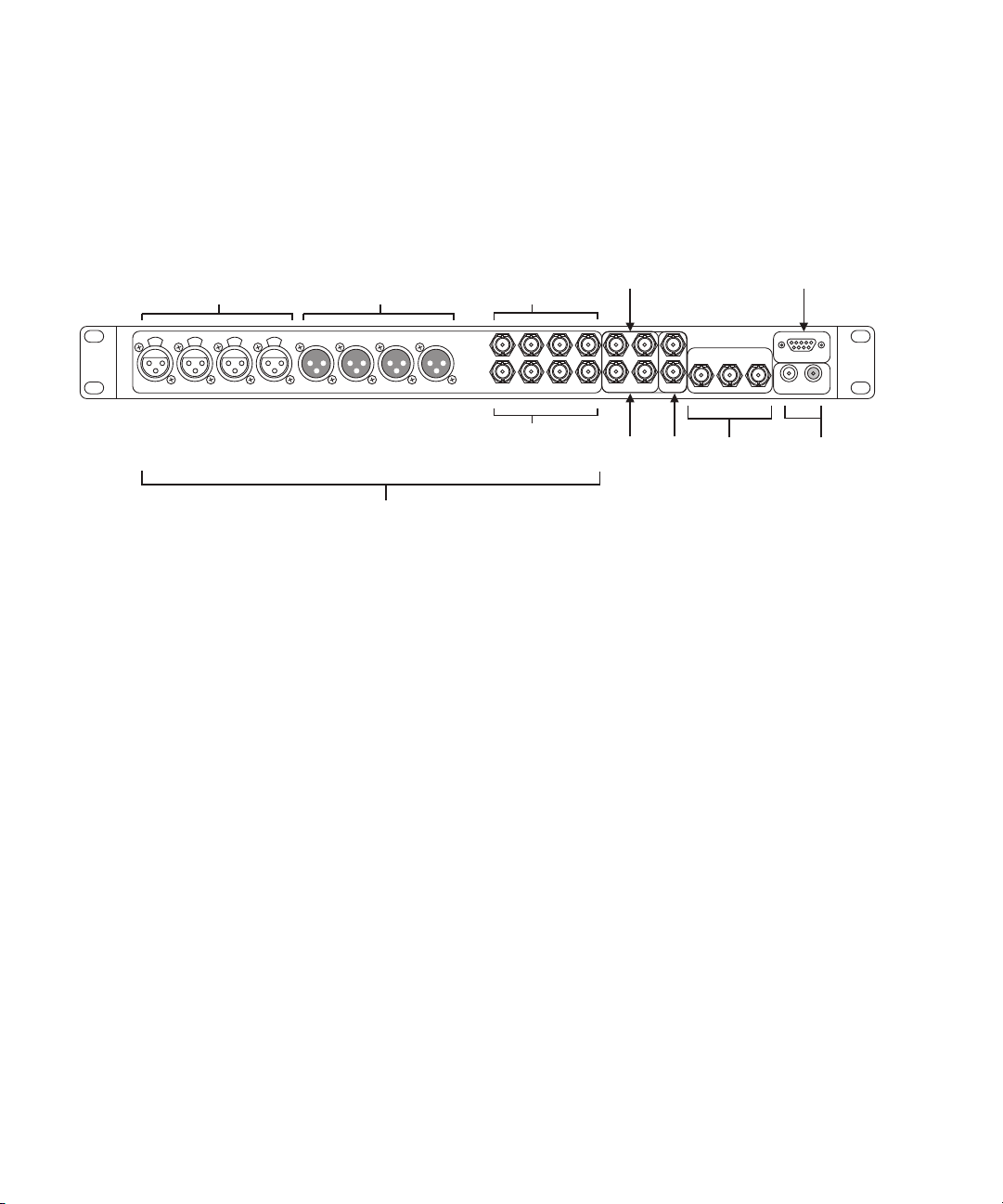
I/O Breakout Box Overview
The I/O breakout box provides a simplified method for connection with only two cables. It
includes BNC connectors:
AES/EBU Audio In
Channels 1 through 8
All AES/EBU audio connectors have two channels
AES/EBU Audio Out
Channels 1 through 8
per connector
Dual-Link Card Connections
The dual-link card comes standard with every Avid DS. It provides the necessary dual-link
input and output channels for high-resolution sources like HDCAM SR and used for capture,
conform, finishing and mastering in high-resolution workflows.
Existing customers can purchase the dual-link card.
n
AES/EBU Audio In
Channels 1 through 8
AES/EBU Audio Out
Channels 1 through 8
Serial
Digital
In
Serial
Digital
Out
External
Reference
(loop)
Component
Composite
Video Output
R5422
Machine
Control
Analog Audio
Output
12
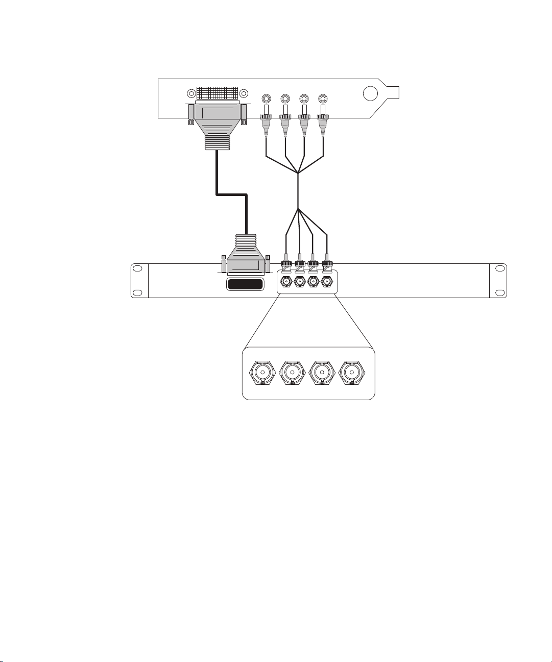
CONNECT TO HOST
SDI In 1/A
In 2/B
Out 1/A
Out 2/B
Mini-BNC cable
HD interconnect cable
Dual-link HD SDI card (Slot 4 on the HP-xw8600)
I/O breakout box (rear view)
I/O Breakout Box Overview
Connect the mini-BNC cable to the corresponding in and out connectors on the I/O breakout
box and the HD SDI dual-link card.
Note that 1/A connectors carry the HD SDI signal, while 2/B connectors carry the SD SDI.
When working with RGB 4:4:4 sequences, both dual-link connectors carry the HD SDI
signal.
The following is a description of the uses of each connector:
• SDI In 1/A and SDI In 2/B: used for capture.
• SDI Out In 1/A and SDI Out 2/B: used for either monitoring or output to tape.
13

4 Avid DS System Setup
Keyboard, Mouse, and Graphics Tablet Connections
The keyboard and mouse come with attached cables for connecting them to the back panel
of your workstation. The Wacom graphic tablet comes with a USB cable.
Avid recommends using extension cables no more than 6 feet (1.83 meters) long for your
keyboard and mouse.
On a rack-mounted workstation, the keyboard port is on the bottom when viewing the back of
n
the workstation base unit and the mouse is to the top.
Monitor Connections
Your workstation comes with one 30-inch monitor, which connects to the NVIDIA graphics
card. For the location of the NVIDIA graphics card refer to the Configuration guidelines for
your workstation.
On a rack-mounted workstation, you can see the graphics card on the left when viewing the
n
back of the workstation base unit.
Each monitor comes with a video cable and a power cord. For information concerning
monitor connections, please refer to the configuration guidelines for your workstation. For
information specific to the graphics card and monitors, see the documentation provided by
the manufacturer.
Whenever possible, the connection from the graphics card to the monitor should be done
n
without an adapter and using the monitor’s native connection.
The driver for the graphics card should be installed on your system, but it is also located on
the Avid DS Software and Drivers DVD. Unique video property settings and system BIOS
are used. For more information consult your Avid representative.
If you find that you are experiencing poor performance, refer to the NVIDIA application
n
content on the Avid DS DVD for required NVIDIA configuration for optimal performance.
Local Storage Systems
Avid DS editing may systems support the Avid MediaDock Ultra320 and Avid VideoRAID
as a local storage system. Local storage connects to the SCSI channels or SAS ports at the
rear of the workstation. You must stripe the drives to provide the needed throughput.
14

Avid Unity Shared Storage Connections
Avid typically supports newer drives as they become available. For the latest list of
n
supported drives, see your Avid sales representative.
The connections at the rear of the workstation are HD 68-pin connectors. If you plan to use
SCSI devices for standalone storage, you must order the cables separately. Normally, the
workstations will not have onboard SCSI controllers. Instead, it uses an Atto UL4D or
UL5D SCSI card with dual-SCSI connectors.
The maximum length of the external SCSI cables must not exceed 16 feet (5 meters). If
connecting two MediaDock Ultra320 enclosures (one enclosure on each SCSI channel), you
can use a 16-foot (5-meter) SCSI cable on each SCSI channel.
For installation procedures and instructions on switching between single-bus and dual-bus
n
modes, see the documentation that ships with the Avid MediaDock Ultra320.
The procedures for formatting and striping media drives depend on the type of storage you
n
use. To format and stripe media drives, see the appropriate storage guide.
If you wish to change your storage, you must first remove the storage location in the Avid
n
Media Indexer before physically removing the storage.
Avid Unity Shared Storage Connections
Avid Unity provides shared storage and networking solutions for sharing media between
multiple workstations. Please refer to the configuration guidelines for your workstation for
the required installation location of the controller card.
Setup and installation instructions for the Avid Unity components ship with the Avid Unity
hardware. For information on installing the Avid Unity network board driver, see the
Avid Unity documentation.
For information on installing and configuring the Avid SAS Storage, also known as the Avid
VideoRAID SR, see the Avid VideoRAID documentation.
Video Deck Connections
You can configure your cables in several ways depending on your camera, video deck, and
client monitor. The audio and video output signals are available to each output connector at
the same time. Avid DS does not include industry-standard video cables. The following
sections describe several possible connections:
You can control this equipment remotely with the serial connection on the workstation (see
“Video Deck Connections” on page 15).
15

4 Avid DS System Setup
Serial
Digital
In
Serial
Digital
Out
AES/EBU Audio In
Channels 1 through 8
AES/EBU Audio In
Channels 1 through 8
AES/EBU Audio Out
Channels 1 through 8
AES/EBU Audio Out
Channels 1 through 8
Video Connections
You can connect HD VTRs and video monitors to your workstation using the Serial Digital
(SD) In and Serial Digital Out connectors.
• You use SDI In 1/A and SDI In 2/B for capture.
• You use SDI Out In 1/A and SDI Out 2/B for either monitoring or output to tape.
Audio Connections
Avid DS uses 8 XLR connectors to carry the audio signal, in AES3 (AES/EBU) format, in
and out of the system. Alternatively, you can use the BNC connectors as shown here. The
selection you make depends on the type of deck you use.
External Monitor Connections
You can connect to an external monitor or hardware that outputs the video to a projector.
16
You can use the following connectors:
Component
Composite
Video Output
•Pr\R\C Out
• Y\G\CBVS Out
• Pb\B\Y Out
Avid DS currently supports 2 component signal formats for monitoring: YPbPr and RGB.
The BNC labeled CBVS also allows composite monitoring.
Reference Signals
Whenever you use more than one video or audio device in your video editing environment,
you must have a separate synchronization signal connected to each device. A sync generator
or reference signal provides a composite signal that locks all the devices (video and audio) to
the main video signal. If the devices are not in sync a monitor might show rolling, tearing, or
incorrect colors in the picture whenever you send video between devices.
Video Deck Connections
To ensure proper sync for your configuration, see the documentation that ships with each of
n
your video devices.
c
Sync Topology
Avid applications require that the VTR and the Avid DS hardware be genlocked to the
same timing source when capturing or outputting a digital cut.
When you sync analog and digital video/audio devices, Avid recommends you feed every
component with a separate black-burst or tri-level sync signal in a star pattern. Avoid
looping the reference signal by terminating any unused loop out with a 75 ohm terminator.
The following illustration shows a typical sync topology:
17
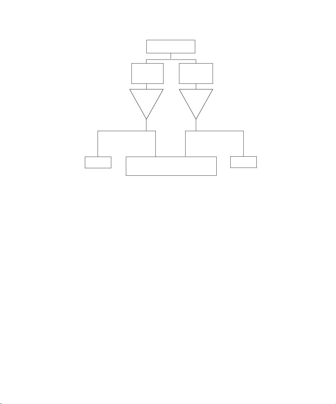
4 Avid DS System Setup
Master reference
signal
To analog
Reference In
SD VTR
NTSC/PAL
black-burst
generator
Video
Distr.
Amp
To SD Sync
Avid DS
Tri-level sync
generator
Video
Distr.
Amp
To HD Tri-level
Sync
To HD
Reference In
HD VTR
You also need to verify the following to ensure correct topology:
• Distance between distribution amplifier (DA): If your DA feeds multiple devices
situated far apart, the stability and strength of the signal it sends is crucial.
• Quality of the devices: A good DA in a star pattern topology is necessary to ensure that
the system properly references very device. You can use an analog video distribution
amplifier to distribute a tri-level sync signal.
• Analog video routing switchers: Avid DS has separate inputs for the SD and HD sync.
Consider using an analog routing switcher to select between the various tri-level sync
signals.
Tri-level Sync and Black Burst Sync
You typically use tri-level sync to synchronize your HD video devices. Tri-level sync
functions similarly to black-burst video in that it maintains the reference synchronizing
information from the facility’s master generator.
You must use a synchronization signal to synchronize your VTR and the DS video
subsystem for all the HD formats supported by Avid DS.
When using SD video, you must connect a black burst or reference signal.
18

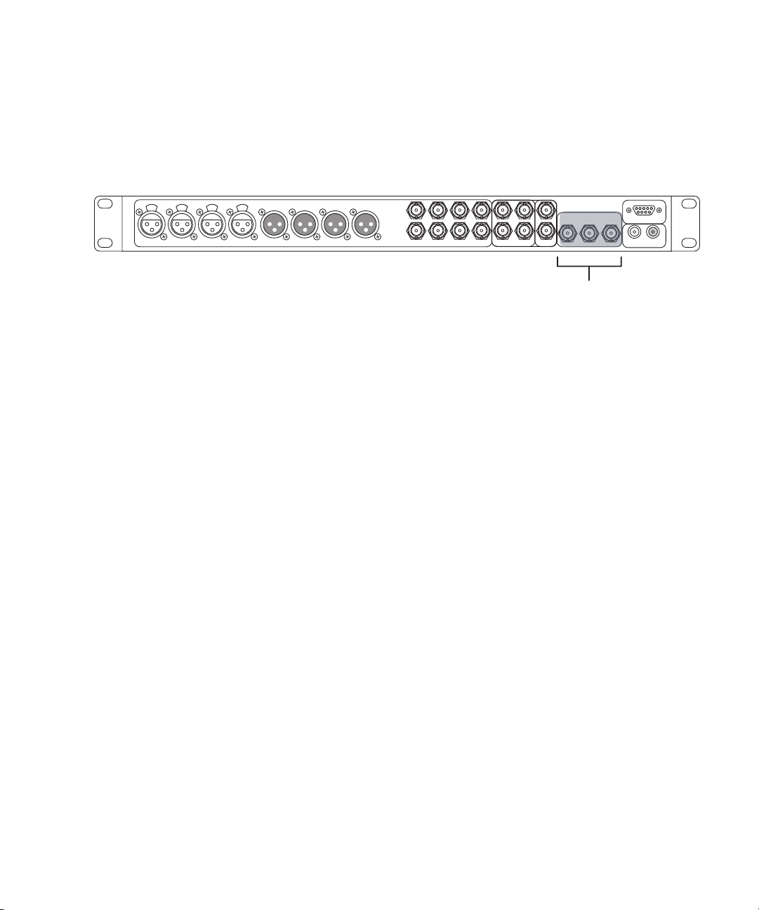
The Reference Signal
External
Reference
(loop)
The I/O breakout box uses the last BNC connector to provide reference signal to the video
card.
Either the black burst signal or tri-level synchronization signal can send a signal to the video
card. Note that if the card does not receive a valid reference signal — for example, a 50Hz
black burst when working in a 1080i 50 sequence — it defaults to free-run mode, also called
internal synchronization. You must have a valid external synchronization signal for any
accurate output to tape and playback operation. The system might experience audio drift or
the loss of audio/video synchronization for invalid synchronization signals. During capture,
the hardware synchronizes to the incoming video signal.
Video Deck Connections
Like most video equipment, the I/O breakout box can synchronize properly with a black
burst signal when working in the following sequence formats:
• 1080i 50 and 59.94 field per second in either color space
• 1080p 25 and 29.97 frames per second in either color space
Other HD formats require a tri-level synchronization signal.
Connecting to the Deck Control
Avid DS does not use the RS-422 machine control connector on the I/O breakout box. You
can control a single deck by using an RS-232 to RS-422 serial adapter. The adapter converts
an RS-232 signal to an RS-422 signal to control a VTR from the Avid DS workstation. An
optional RS-232 to RS-422 serial adapter kit is available through Avid.
The adapters include two diagnostic LEDs (power and data). The power LED glows steadily
when the adapter receives adequate power through the serial port. The data LED flashes
whenever data is transmitted or received. This helps you confirm that the serial port is active.
The optional serial adapter kit contains the following:
• An RS-232 to RS-422 serial adapter
• Two serial cables with 9-pin male connectors at both ends
19

4 Avid DS System Setup
RS-422 connection Serial Adapter RS-232 connection
To Avid DS Workstation To video deck
To connect a single deck to your system:
1. Locate the serial adapter kit.
2. Attach one end of a 9-pin cable to the end of the serial adapter labeled RS-232.
3. Attach the other end of the 9-pin cable to the serial port on the workstation or to the
serial connector of the USB-to-serial adapter.
4. Attach one end of another 9-pin cable to the end of the serial adapter labeled RS-422.
5. Attach the other end of the 9-pin cable to the remote serial port of the video deck.
Place the deck in Remote mode before attempting to control the deck using the software. See
n
the documentation provided with your deck.
Serial and MIDI Port Device Connections
Avid systems support the connection of two different MIDI fader controllers and a
JL Cooper Media Control Station3 (MCS3) jog/shuttle wheel. The fader controllers and the
mixer connect to the MIDISPORT™ 2x2 USB-to-MIDI converter attached to the USB ports.
The two fader controllers are the JL Cooper FaderMaster Pro and the JL Cooper
MCS-3800X. Avid supports recording automation gain using the MIDI features of the
mixer.
USB and Serial Connections
Windows systems typically have 2 or more USB connections and one serial connection. If
you need more than one serial connection, Avid recommends using a USB-to-serial adapter.
See the documentation that comes with the device.
Connecting the USB-to-MIDI Converter
When using a JL Cooper controller, you must install a USB-to-MIDI converter. If you use
the EDIROL UM-1, you must install the latest version of the EDIROL UM-1 driver first
before using it.
20

Connecting JL Cooper Fader Controllers
Avid DS System
USB-to-MIDI Converter
Audio Device
MIDI IN
MIDI OUT
MIDI OUT
Port
MIDI IN
Port
Advanced
ON
OFF
The following diagram shows how to connect the USB-to-MIDI converter to your computer
and audio device.
To connect the USB-to-MIDI converter to your computer and audio device:
1. Switch the Advanced mode on the USB-to-MIDI converter to ON.
2. Connect the USB cable of the USB-to-MIDI converter to a USB port on the computer or
to a USB hub.
3. If you want to use this audio device to play music from your computer, connect the
MIDI OUT cable to the MIDI IN port of your audio device.
4. If you want to use this audio device to transmit data into your computer, connect the
MIDI IN cable to the MIDI OUT port of your audio device.
Connecting JL Cooper Fader Controllers
Your Avid DS system supports the FaderMaster Pro and the MCS-3800X fader controllers.
Both of the fader controllers connect to a USB-to-MIDI converter that connects to a USB
port on the system.
The Avid DS system supports the JL Cooper MCS-3800 media command station. For more
n
details, see the Avid DS Support Center web site.
There are two major differences between the MCS-3800X and the FaderMaster Pro:
• The MCS-3800X has a four-position switchpack (not available on the FaderMaster Pro).
• The MCS-3800X and the FaderMaster Pro locate the MIDI IN and MIDI OUT in
opposite positions.
The following diagram illustrates the JL Cooper MCS-3800K Fader Controller cabling.
21

4 Avid DS System Setup
Power
9VDC
MIDI In MIDI Out
Switch In Switch Out
+
_
In B
Out B
Out A
MIDI cable
MIDI IN
MIDI OUT
USB-to-MIDI converter
(rear)
MIDI cable to In A
IN A
IN A IN B
OUT A OUT B
USB/
MIDI
Thru
USB
Button (In position)
USB-to-MIDI converter
(front)
CTS 206-4
ON
MIDI cable
1 2 3 4
EXPANDER
SELECT
POWER
ON
MIDI OUT MIDI IN
In B
Out A
MIDI cable to In A
Out B
Button (In position)
IN A IN B
OUT A OUT B
IN A
USB-to-MIDI converter
(front)
USB/
MIDI
Thru
USB
The following diagram illustrates the JL Cooper FaderMaster Pro Fader Controller cabling.
22

Connecting JL Cooper Fader Controllers
To connect the fader controllers:
1. Quit any open applications.
2. Shut down the Avid DS workstation.
3. Make sure you connect your USB-to-MIDI converter to the USB port (see “Connecting
the USB-to-MIDI Converter” on page 20).
4. If you plan to cable the MCS-3800X, set switch 4 to the ON (down) position. The
switch is upside down on the MCS-3800X.
5. Locate two MIDI cables with 5-pin DIN connectors.
You can use the In A and Out A connector pair or the In B and Out B connector pair on the
n
rear of the USB-to-MIDI converter. Make sure you select the corresponding port when
configuring the device using the Controller Settings dialog box on Avid DS.
6. Plug one end of the first MIDI cable into the In A connector of the USB-to-MIDI
converter, and the other end of the cable into the MIDI OUT connector of the fader
controller.
7. Plug one end of the second MIDI cable into the Out A connector of the USB-to-MIDI
converter, and the other end of the cable into the MIDI IN connector of the fader
controller.
8. Make sure the button on the front of the USB-to-MIDI converter is pushed in.
Refer to External Controller Setup on the Avid DS Support site or Using an External
n
Controller in the Avid DS Help for information on interfacing with the Avid DS software.
23

4 Avid DS System Setup
24

Index
Index
A
Avid Unity
Fibre Channel board
Avid Unity ISIS
Avid Unity MediaNetwork 15
15
B
Black burst
reference described
18
C
Cables
serial control
Computer monitors, connecting
Connecting
video decks
Connecting hardware
computer monitors
keyboard
monitors
peripheral devices
video devices
connecting hardware
External monitor
Connectors
I/O breakout box
Controlling a deck 19
19
15
14
14
14
15
16, 16
16
12
D
Devices
peripheral, connecting
15
E
Environmental requirements 9
External monitor, connecting
16
14
F
Fader controller
connecting JL Cooper
21
G
Graphics card 14
H
Hardware 14
monitors, connecting
HD SDI card
connecting
12
14
I
I/O breakout box
Connectors
front panel
installing in rack
12
12
11
J
JL Cooper fader controllers
connecting
21
M
MCS-3000X fader controller, connecting 21
Media network
MediaDock Ultra320
connection
Monitors
connecting
15
14
14
N
Network
Avid Unity
15
25

Index
O
Optional serial adapter kit 19
P
Peripherals devices 15
Planning, site 9
electrical requirements
environmental requirements
10
R
Rack-mount
securing the I/O breakout box in
Requirements
electrical
environmental
RS-232 to RS-422 serial adapter
9
10
9
S
SCSI storage systems 14
Serial control
controlling a video deck
Site planning Requirements
environmental
Site planning requirements
electrical
sync
17
house
topology
System requirements
electrical
environmental 9
site planning
9
10
17
10
9
19
9
9
19
11
Video devices, connecting
16, 16
U
Unity
See Avid Unity
USB-to-MIDI converter
V
Video deck
controlling 19
26
20
 Loading...