

Page 1

Avid® DekoCast™ Products
User’s Guide
Page 2

Copyright and Disclaimer
Product specifications are subject to change without notice and do not represent a commitment on the part of
Avid Technology, Inc.
This product is subject to the terms and conditions of a software license agreement provided with the software. The product
may only be used in accordance with the license agreemen.
Avid products or portions thereof are protected by one or more of the following United States Patents: 5,267,351; 5,309,528;
5,355,450; 5,396,594; 5,440,348; 5,467,288; 5,513,375; 5,528,310; 5,557,423; 5,577,190; 5,584,006; 5,640,601; 5,644,364;
5,654,737; 5,724,605; 5,726,717; 5,745,637; 5,752,029; 5,754,851; 5,799,150; 5,812,216; 5,828,678; 5,842,014; 5,852,435;
5,986,584; 5,999,406; 6,038,573; 6,061,758; 6,069,668; 6,141,007; 6,211,869; 6,532,043; 6,546,190; 6,596,031; 6,636,869;
6,747,705; 6,763,523; 6,766,357; 6,813,622; 6,847,373; 7,081,900; RE40,107; 7,403,561; 7,433,519; 7,671,871; D352,278;
D372,478; D373,778; D392,267; D392,268; D392,269; D395,291; D396,853; D398,912. Other patents are pending.
Avid products or portions thereof are protected by one or more of the following European Patents: 0506870; 0635188;
0674414; 0752174; 1111910; 1629675. Other patents are pending.
This document is protected under copyright law. An authorized licensee of Avid DekoCast may reproduce this publication for
the licensee’s own use in learning how to use the software. This document may not be reproduced or distributed, in whole or in
part, for commercial purposes, such as selling copies of this document or providing support or educational services to others.
This document is supplied as a guide for Avid DekoCast. Reasonable care has been taken in preparing the information it
contains. However, this document may contain omissions, technical inaccuracies, or typographical errors. Avid Technology,
Inc. does not accept responsibility of any kind for customers’ losses due to the use of this document. Product specifications
are subject to change without notice.
Copyright © 2010 Avid Technology, Inc. and its licensors. All rights reserved. Printed in USA.
The following disclaimer is required by Apple Computer, Inc.:
APPLE COMPUTER, INC. MAKES NO WARRANTIES WHATSOEVER, EITHER EXPRESS OR IMPLIED, REGARDING
THIS PRODUCT, INCLUDING WARRANTIES WITH RESPECT TO ITS MERCHANTABILITY OR ITS FITNESS FOR ANY
PARTICULAR PURPOSE. THE EXCLUSION OF IMPLIED WARRANTIES IS NOT PERMITTED BY SOME STATES. THE
ABOVE EXCLUSION MAY NOT APPLY TO YOU. THIS WARRANTY PROVIDES YOU WITH SPECIFIC LEGAL RIGHTS.
THERE MAY BE OTHER RIGHTS THAT YOU MAY HAVE WHICH VARY FROM STATE TO STATE.
The following disclaimer is required by Sam Leffler and Silicon Graphics, Inc. for the use of their TIFF library:
Copyright © 1988–1997 Sam Leffler
Copyright © 1991–1997 Silicon Graphics, Inc.
Permission to use, copy, modify, distribute, and sell this software [i.e., the TIFF library] and its documentation for any purpose
is hereby granted without fee, provided that (i) the above copyright notices and this permission notice appear in all copies of
the software and related documentation, and (ii) the names of Sam Leffler and Silicon Graphics may not be used in any
advertising or publicity relating to the software without the specific, prior written permission of Sam Leffler and Silicon
Graphics.
THE SOFTWARE IS PROVIDED “AS-IS” AND WITHOUT WARRANTY OF ANY KIND, EXPRESS, IMPLIED OR
OTHERWISE, INCLUDING WITHOUT LIMITATION, ANY WARRANTY OF MERCHANTABILITY OR FITNESS FOR A
PARTICULAR PURPOSE.
IN NO EVENT SHALL SAM LEFFLER OR SILICON GRAPHICS BE LIABLE FOR ANY SPECIAL, INCIDENTAL, INDIRECT
OR CONSEQUENTIAL DAMAGES OF ANY KIND, OR ANY DAMAGES WHATSOEVER RESULTING FROM LOSS OF USE,
DATA OR PROFITS, WHETHER OR NOT ADVISED OF THE POSSIBILITY OF DAMAGE, AND ON ANY THEORY OF
LIABILITY, ARISING OUT OF OR IN CONNECTION WITH THE USE OR PERFORMANCE OF THIS SOFTWARE.
The following disclaimer is required by the Independent JPEG Group:
This software is based in part on the work of the Independent JPEG Group.
The following disclaimer is required by Paradigm Matrix:
Portions of this software licensed from Paradigm Matrix.
2
Page 3

The following disclaimer is required by Ray Sauers Associates, Inc.:
“Install-It” is licensed from Ray Sauers Associates, Inc. End-User is prohibited from taking any action to derive a source code
equivalent of “Install-It,” including by reverse assembly or reverse compilation, Ray Sauers Associates, Inc. shall in no event be
liable for any damages resulting from reseller’s failure to perform reseller’s obligation; or any damages arising from use or
operation of reseller’s products or the software; or any other damages, including but not limited to, incidental, direct, indirect,
special or consequential Damages including lost profits, or damages resulting from loss of use or inability to use reseller’s
products or the software for any reason including copyright or patent infringement, or lost data, even if Ray Sauers Associates
has been advised, knew or should have known of the possibility of such damages.
The following disclaimer is required by Videomedia, Inc.:
“Videomedia, Inc. makes no warranties whatsoever, either express or implied, regarding this product, including warranties with
respect to its merchantability or its fitness for any particular purpose.”
“This software contains V-LAN ver. 3.0 Command Protocols which communicate with V-LAN ver. 3.0 products developed by
Videomedia, Inc. and V-LAN ver. 3.0 compatible products developed by third parties under license from Videomedia, Inc. Use
of this software will allow “frame accurate” editing control of applicable videotape recorder decks, videodisc recorders/players
and the like.”
The following disclaimer is required by Altura Software, Inc. for the use of its Mac2Win software and Sample
Source Code:
©1993–1998 Altura Software, Inc.
The following disclaimer is required by Ultimatte Corporation:
Certain real-time compositing capabilities are provided under a license of such technology from Ultimatte Corporation and are
subject to copyright protection.
The following disclaimer is required by 3Prong.com Inc.:
Certain waveform and vector monitoring capabilities are provided under a license from 3Prong.com Inc.
Attn. Government User(s). Restricted Rights Legend
U.S. GOVERNMENT RESTRICTED RIGHTS. This Software and its documentation are “commercial computer software” or
“commercial computer software documentation.” In the event that such Software or documentation is acquired by or on behalf
of a unit or agency of the U.S. Government, all rights with respect to this Software and documentation are subject to the terms
of the License Agreement, pursuant to FAR §12.212(a) and/or DFARS §227.7202-1(a), as applicable.
Trademarks
Trademarks
003, 192 Digital I/O, 192XD I/O, 888 I/O, AirPlay, AirSPACE, AirSPACE HD, AirSpeed, ALEX, Alienbrain, AniMatte,
AudioMarket, AudioPages, AudioSuite, AudioVision, AutoSync, Avid, Avid Advanced Response, Avid DNA, Avid DNxcel,
Avid DNxHD, AVIDdrive, Avid DS Assist Station, Avid EditStar, Avid Learning Excellerator, Avid Liquid,
Avid Liquid Chrome Xe, Avid MEDIArray, Avid Mojo, AvidNet, AvidNetwork, Avid NewStar, Avid Remote Response,
AVIDstripe, Avid Unity, Avid Unity ISIS, Avid VideoRAID, Avid Xpress, AVoption, AVX, Beauty Without The Bandwidth, Boom,
C|24, CaptureManager, ChromaCurve, ChromaWheel, Command|24, Conectiv, CountDown, DAE, Dazzle,
Dazzle Digital Video Creator, Deko, DekoCast, D-Fi, D-fx, DigiDelivery, Digidesign, Digidesign Audio Engine,
Digidesign Intelligent Noise Reduction, DigiDrive, DigiLink, DigiMeter, DigiSerial, DigiStudio, DigiStudio Control,
Digital Nonlinear Accelerator, DigiTranslator, DINR, DNxchange, do more, DVD Complete, D-Verb, Eleven, Equinox,
EveryPhase, ExpertRender, Fastbreak, Fast Track, FieldPak, Film Composer, FilmScribe, Flexevent, FluidMotion, FXDeko,
G7, G-Rack, HD Core, HD Process, HDPack, HYBRID, HyperControl, HyperSPACE, HyperSPACE HDCAM, IllusionFX,
Image Independence, iNEWS, iNEWS Assign, iNEWS ControlAir, Instantwrite, Instinct,
Intelli-sat Broadcasting Recording Manager, Intelli-Sat, InterFX, Interplay, inTONE, Intraframe, iS9, iS18, iS23, iS36, ISIS,
IsoSync, KeyRig, KeyStudio, LaunchPad, LeaderPlus, Lightning, ListSync, Lo-Fi, Magic Mask, Make Anything Hollywood,
make manage move | media, Marquee, M-Audio, M-Audio Micro, Maxim, Mbox, MCXpress, Media Browse, Media Composer,
MediaDock, MediaDock Shuttle, Media Fusion, Media Illusion, MediaLog, Media Reader, Media Recorder, MEDIArray,
MediaShare, MediaStream, Media Suite, Meridien, MetaFuze, MetaSync, MicroTrack, Midiman, MissionControl, Mix Rack,
MixLab, Moviebox, Moviestar, NaturalMatch, Nearchive, NetReview, NewsCutter, Nitris, NRV-10 interFX, Octane, OMF,
OMF Interchange, OMM, OnDVD, Open Media Framework, Open Media Management, Palladium, Pinnacle,
Pinnacle DistanTV, Pinnacle Geniebox, Pinnacle HomeMusic, Pinnacle MediaSuite, Pinnacle Mobile Media, Pinnacle Studio,
Pinnacle Studio MovieBoard, Pinnacle Systems, ProEncode, ProServices, ProSessions, Pro Tools, QuietDrive, Recti-Fi,
Reel Tape Delay, Reel Tape Flanger, Reel Tape Saturation, RetroLoop, rS9, rS18, Salesview, Sci-Fi, Scorch, Scorefitter,
ScriptSync, SecureProductionEnvironment, Session, Show Center, Sibelius, SIDON, Soft SampleCell, Soft-Clip Limiter,
Sound Designer II, SPACE, SPACEShift, SpectraGraph, SpectraMatte, Sputnik, Starplay, SteadyGlide, Streamfactory,
Streamgenie, StreamRAID, Strike, Structure, Studiophile, SubCap, Sundance Digital, Sundance, Symphony, SYNC HD,
3
Page 4

SynchroScience, SynchroScope, Syntax, TDM FlexCable, Thunder, Titan, Titansync, TL Aggro, TL AutoPan, TL Drum Rehab,
TL Everyphase, TL Fauxlder, TL In Tune, TL MasterMeter, TL Metro, TL Space, TL Utilities, Torq, Torq Xponent, Transfuser,
Trigger Finger, Trillium Lane Labs, TruTouch, UnityRAID, Vari-Fi, Velvet, Venom, VideoRAID, Video Slave Driver, VideoSPACE,
VideoSpin, Vortx, Xdeck, X-Form, Xmon, Xponent, and X-Session are either registered trademarks or trademarks of Avid
Technology, Inc. in the United States and/or other countries.
Adobe and Photoshop are either registered trademarks or trademarks of Adobe Systems Incorporated in the
United States and/or other countries. Apple and Macintosh are trademarks of Apple Computer, Inc., registered
in the U.S. and other countries. Windows is either a registered trademark or trademark of Microsoft
Corporation in the United States and/or other countries.
iNEWS, iNEWS ControlAir, and Media Browse are either registered trademarks or trademarks of iNews, LLC.
All other trademarks contained herein are the property of their respective owners.
GOT FOOTAGE?
Editors — Filmmakers — Special Effects Artists — Game Developers — Animators — Educators — Broadcasters — Content
creators of every genre — Just finished an incredible project and want to share it with the world?
Send us your reels and we may use your footage in our show reel or demo!*
For a copy of our release and Avid’s mailing address, go to www.avid.com/footage.
*Note: Avid cannot guarantee the use of materials submitted.
Avid DekoCast Products User Guide • 0130-07809-01 Rev B • April 2010
4
Page 5

Contents
Symbols and Conventions . . . . . . . . . . . . . . . . . . . . . . . . . . . . . . . . . . . . . . . . . . . . 18
If You Need Help. . . . . . . . . . . . . . . . . . . . . . . . . . . . . . . . . . . . . . . . . . . . . . . . . . . . 19
Accessing the Online Library . . . . . . . . . . . . . . . . . . . . . . . . . . . . . . . . . . . . . . . . . . 19
How to Order Documentation . . . . . . . . . . . . . . . . . . . . . . . . . . . . . . . . . . . . . . . . . . 20
Avid Training Services . . . . . . . . . . . . . . . . . . . . . . . . . . . . . . . . . . . . . . . . . . . . . . . 20
Chapter 1 Getting Started . . . . . . . . . . . . . . . . . . . . . . . . . . . . . . . . . . . . . . . . . . . . . . 21
Why Use DekoCast?. . . . . . . . . . . . . . . . . . . . . . . . . . . . . . . . . . . . . . . . . . . . . . . . . 22
DekoCast Products and Applications . . . . . . . . . . . . . . . . . . . . . . . . . . . . . . . . . . . . 23
DekoCast Workflow. . . . . . . . . . . . . . . . . . . . . . . . . . . . . . . . . . . . . . . . . . . . . . . . . . 25
Controlling DekoCast On-Air Video Output. . . . . . . . . . . . . . . . . . . . . . . . . . . . . . . . 26
Before You Begin . . . . . . . . . . . . . . . . . . . . . . . . . . . . . . . . . . . . . . . . . . . . . . . . . . . 27
Starting and Closing DekoCast Applications. . . . . . . . . . . . . . . . . . . . . . . . . . . . . . . 27
Switching Between Video Formats . . . . . . . . . . . . . . . . . . . . . . . . . . . . . . . . . . . . . . 29
Configuring Your DekoCast System . . . . . . . . . . . . . . . . . . . . . . . . . . . . . . . . . . . . . 29
Basic Components . . . . . . . . . . . . . . . . . . . . . . . . . . . . . . . . . . . . . . . . . . . . . . . . . . 30
DekoCast Main Window. . . . . . . . . . . . . . . . . . . . . . . . . . . . . . . . . . . . . . . . . . . 30
Scenes . . . . . . . . . . . . . . . . . . . . . . . . . . . . . . . . . . . . . . . . . . . . . . . . . . . . . . . . 31
Objects . . . . . . . . . . . . . . . . . . . . . . . . . . . . . . . . . . . . . . . . . . . . . . . . . . . . . . . . 31
Scene Tree. . . . . . . . . . . . . . . . . . . . . . . . . . . . . . . . . . . . . . . . . . . . . . . . . . . . . 32
Object Editors. . . . . . . . . . . . . . . . . . . . . . . . . . . . . . . . . . . . . . . . . . . . . . . . . . . 33
Actions and the Timeline Editor . . . . . . . . . . . . . . . . . . . . . . . . . . . . . . . . . . . . . 34
Performance Tab . . . . . . . . . . . . . . . . . . . . . . . . . . . . . . . . . . . . . . . . . . . . . . . . 34
Parameters Tab . . . . . . . . . . . . . . . . . . . . . . . . . . . . . . . . . . . . . . . . . . . . . . . . . 35
Log Pane . . . . . . . . . . . . . . . . . . . . . . . . . . . . . . . . . . . . . . . . . . . . . . . . . . . . . . 36
Adjusting the DekoCast Window . . . . . . . . . . . . . . . . . . . . . . . . . . . . . . . . . . . . 36
Online Help. . . . . . . . . . . . . . . . . . . . . . . . . . . . . . . . . . . . . . . . . . . . . . . . . . . . . 37
Understanding Files and File Types . . . . . . . . . . . . . . . . . . . . . . . . . . . . . . . . . . . . . 37
Page 6

Setting Up Directories . . . . . . . . . . . . . . . . . . . . . . . . . . . . . . . . . . . . . . . . . . . . 37
Scene Files . . . . . . . . . . . . . . . . . . . . . . . . . . . . . . . . . . . . . . . . . . . . . . . . . . . . 40
Supported File Formats. . . . . . . . . . . . . . . . . . . . . . . . . . . . . . . . . . . . . . . . . . . 41
Copying Files. . . . . . . . . . . . . . . . . . . . . . . . . . . . . . . . . . . . . . . . . . . . . . . . . . . 42
Viewing Information About Your DekoCast System. . . . . . . . . . . . . . . . . . . . . . . . . 44
Quick Start: Fading a Graphic On and Off . . . . . . . . . . . . . . . . . . . . . . . . . . . . . . . . 45
Before You Begin . . . . . . . . . . . . . . . . . . . . . . . . . . . . . . . . . . . . . . . . . . . . . . . 45
Creating a Scene. . . . . . . . . . . . . . . . . . . . . . . . . . . . . . . . . . . . . . . . . . . . . . . . 46
Adding Objects . . . . . . . . . . . . . . . . . . . . . . . . . . . . . . . . . . . . . . . . . . . . . . . . . 47
Adding Actions . . . . . . . . . . . . . . . . . . . . . . . . . . . . . . . . . . . . . . . . . . . . . . . . . 51
Playing the Scene in DekoCast Central . . . . . . . . . . . . . . . . . . . . . . . . . . . . . . 55
Using the Sample Scenes and Media . . . . . . . . . . . . . . . . . . . . . . . . . . . . . . . . . . . 57
Chapter 2 Working with Scenes and Objects . . . . . . . . . . . . . . . . . . . . . . . . . . . . . . 59
Scenes Pane and Toolbar . . . . . . . . . . . . . . . . . . . . . . . . . . . . . . . . . . . . . . . . . . . . 59
Creating a New Scene . . . . . . . . . . . . . . . . . . . . . . . . . . . . . . . . . . . . . . . . . . . . . . . 61
Renaming and Saving a Scene . . . . . . . . . . . . . . . . . . . . . . . . . . . . . . . . . . . . . . . . 62
Opening an Existing Scene . . . . . . . . . . . . . . . . . . . . . . . . . . . . . . . . . . . . . . . . . . . 63
Working with Objects . . . . . . . . . . . . . . . . . . . . . . . . . . . . . . . . . . . . . . . . . . . . . . . . 64
Adding Objects to the Scene Tree . . . . . . . . . . . . . . . . . . . . . . . . . . . . . . . . . . 64
Objects Overview . . . . . . . . . . . . . . . . . . . . . . . . . . . . . . . . . . . . . . . . . . . . . . . 66
Renaming Objects. . . . . . . . . . . . . . . . . . . . . . . . . . . . . . . . . . . . . . . . . . . . . . . 69
Working with the Scene Tree . . . . . . . . . . . . . . . . . . . . . . . . . . . . . . . . . . . . . . . . . . 70
Expanding or Collapsing a Branch . . . . . . . . . . . . . . . . . . . . . . . . . . . . . . . . . . 70
Deleting Objects . . . . . . . . . . . . . . . . . . . . . . . . . . . . . . . . . . . . . . . . . . . . . . . . 71
Inserting a Scene within a Scene Tree . . . . . . . . . . . . . . . . . . . . . . . . . . . . . . . 71
How Objects Are Composited . . . . . . . . . . . . . . . . . . . . . . . . . . . . . . . . . . . . . . 72
Understanding Grouped Objects. . . . . . . . . . . . . . . . . . . . . . . . . . . . . . . . . . . . 73
Rearranging Objects in the Scene Tree . . . . . . . . . . . . . . . . . . . . . . . . . . . . . . 73
Understanding Parent-Child Relationships . . . . . . . . . . . . . . . . . . . . . . . . . . . . 74
Selecting Scenes for Output. . . . . . . . . . . . . . . . . . . . . . . . . . . . . . . . . . . . . . . . . . . 75
Multiple Scenes and Stacking Order . . . . . . . . . . . . . . . . . . . . . . . . . . . . . . . . . . . . 76
Chapter 3 Editing Objects in the Scene. . . . . . . . . . . . . . . . . . . . . . . . . . . . . . . . . . . 79
Using an Object Editor . . . . . . . . . . . . . . . . . . . . . . . . . . . . . . . . . . . . . . . . . . . . . . . 80
6
Page 7

Editing Video Out Objects. . . . . . . . . . . . . . . . . . . . . . . . . . . . . . . . . . . . . . . . . . . . . 81
Setting Background Color and Opacity . . . . . . . . . . . . . . . . . . . . . . . . . . . . . . . 81
Selecting a Custom Background Color . . . . . . . . . . . . . . . . . . . . . . . . . . . . . . . 82
Editing Video In Objects . . . . . . . . . . . . . . . . . . . . . . . . . . . . . . . . . . . . . . . . . . . . . . 84
Selecting a Video Input Port. . . . . . . . . . . . . . . . . . . . . . . . . . . . . . . . . . . . . . . . 84
Changing the Opacity of a Video Input Object . . . . . . . . . . . . . . . . . . . . . . . . . . 85
Using the Target and Position Tabs . . . . . . . . . . . . . . . . . . . . . . . . . . . . . . . . . . . . . 86
Arranging Objects for Video Output . . . . . . . . . . . . . . . . . . . . . . . . . . . . . . . . . . 86
Using Screen Coordinates . . . . . . . . . . . . . . . . . . . . . . . . . . . . . . . . . . . . . . . . . 87
Using Thumbwheel Controls . . . . . . . . . . . . . . . . . . . . . . . . . . . . . . . . . . . . . . . 88
Using the Target Tab . . . . . . . . . . . . . . . . . . . . . . . . . . . . . . . . . . . . . . . . . . . . . 89
Defining a Target Rectangle . . . . . . . . . . . . . . . . . . . . . . . . . . . . . . . . . . . . 89
Scaling an Object in Relation to Its Target Rectangle. . . . . . . . . . . . . . . . . 91
Using The Position Tab . . . . . . . . . . . . . . . . . . . . . . . . . . . . . . . . . . . . . . . . . . . 95
Changing an Object’s Position and Scale . . . . . . . . . . . . . . . . . . . . . . . . . . 95
Cropping an Object . . . . . . . . . . . . . . . . . . . . . . . . . . . . . . . . . . . . . . . . . . . 96
Designing Your Layout. . . . . . . . . . . . . . . . . . . . . . . . . . . . . . . . . . . . . . . . . . . . 96
Guidelines for Using Target Rectangles . . . . . . . . . . . . . . . . . . . . . . . . . . . 97
Suggestions for Preparing Your Layout. . . . . . . . . . . . . . . . . . . . . . . . . . . . 99
Transferring a Layout to a Scene . . . . . . . . . . . . . . . . . . . . . . . . . . . . . . . 100
Example: Defining a Target Rectangle for Video In . . . . . . . . . . . . . . . . . 100
Using the Levels and Mixer Tabs . . . . . . . . . . . . . . . . . . . . . . . . . . . . . . . . . . . . . . 103
Using the Levels Tab . . . . . . . . . . . . . . . . . . . . . . . . . . . . . . . . . . . . . . . . . . . . 103
Using the Mixer Tab . . . . . . . . . . . . . . . . . . . . . . . . . . . . . . . . . . . . . . . . . . . . . 105
Understanding Color Coding in the Levels and Mixing Tabs . . . . . . . . . . . . . . 106
Working with Deko Objects . . . . . . . . . . . . . . . . . . . . . . . . . . . . . . . . . . . . . . . . . . . 108
Adding a Deko Object to a Scene . . . . . . . . . . . . . . . . . . . . . . . . . . . . . . . . . . 109
Example: Deko Object with Ten Text Layers . . . . . . . . . . . . . . . . . . . . . . 112
Guidelines for Adding Deko Objects . . . . . . . . . . . . . . . . . . . . . . . . . . . . . 113
Editing and Updating Deko Objects . . . . . . . . . . . . . . . . . . . . . . . . . . . . . . . . . 114
Naming Layers in PostDeko Lite . . . . . . . . . . . . . . . . . . . . . . . . . . . . . . . . . . . 114
Positioning and Sizing a Deko Object . . . . . . . . . . . . . . . . . . . . . . . . . . . . . . . 115
Adjusting Opacity . . . . . . . . . . . . . . . . . . . . . . . . . . . . . . . . . . . . . . . . . . . . . . . 116
7
Page 8

Working with Text . . . . . . . . . . . . . . . . . . . . . . . . . . . . . . . . . . . . . . . . . . . . . . 116
Using the Text Override Option . . . . . . . . . . . . . . . . . . . . . . . . . . . . . . . . 117
Using the Contents Tab . . . . . . . . . . . . . . . . . . . . . . . . . . . . . . . . . . . . . . 119
Using Text Files . . . . . . . . . . . . . . . . . . . . . . . . . . . . . . . . . . . . . . . . . . . . 121
Displaying Crawls and Rolls . . . . . . . . . . . . . . . . . . . . . . . . . . . . . . . . . . . 123
Transition Options for Deko Object Text . . . . . . . . . . . . . . . . . . . . . . . . . 125
Looping Options for Deko Object Text . . . . . . . . . . . . . . . . . . . . . . . . . . . 127
Managing Text Display . . . . . . . . . . . . . . . . . . . . . . . . . . . . . . . . . . . . . . . 128
Using Embedded Tags with Deko Object Text. . . . . . . . . . . . . . . . . . . . . 128
Displaying Clocks . . . . . . . . . . . . . . . . . . . . . . . . . . . . . . . . . . . . . . . . . . . . . . 131
Displaying a Time-of-Day Clock . . . . . . . . . . . . . . . . . . . . . . . . . . . . . . . . 131
Displaying a Count-Up or Count-Down Timer . . . . . . . . . . . . . . . . . . . . . 133
Deko Object Clock Formats . . . . . . . . . . . . . . . . . . . . . . . . . . . . . . . . . . . 133
Displaying Temperature . . . . . . . . . . . . . . . . . . . . . . . . . . . . . . . . . . . . . . . . . 136
Playing Back Audio . . . . . . . . . . . . . . . . . . . . . . . . . . . . . . . . . . . . . . . . . . . . . . . . 136
Capturing Audio . . . . . . . . . . . . . . . . . . . . . . . . . . . . . . . . . . . . . . . . . . . . . . . . . . . 138
Playing Back Clips . . . . . . . . . . . . . . . . . . . . . . . . . . . . . . . . . . . . . . . . . . . . . . . . . 140
Understanding Clip Playback . . . . . . . . . . . . . . . . . . . . . . . . . . . . . . . . . . . . . 141
Managing Clip Playback . . . . . . . . . . . . . . . . . . . . . . . . . . . . . . . . . . . . . . . . . 143
Clip Playback File and Compression Formats. . . . . . . . . . . . . . . . . . . . . . . . . 143
Adding and Defining a Clip Playback Object. . . . . . . . . . . . . . . . . . . . . . . . . . 144
Clip Playback Object Options . . . . . . . . . . . . . . . . . . . . . . . . . . . . . . . . . . . . . 147
Playing and Looping Clips. . . . . . . . . . . . . . . . . . . . . . . . . . . . . . . . . . . . . . . . 148
Transcoding SD Clips to MPEG-2 MXF I-Frame. . . . . . . . . . . . . . . . . . . . . . . 149
Suggested Workflow for Transcoding. . . . . . . . . . . . . . . . . . . . . . . . . . . . 151
Transcoding Clips Through the Transcode Application . . . . . . . . . . . . . . 152
Transcoding By Dragging Clips to the Transcode Icon . . . . . . . . . . . . . . 158
Transcoding Clips By Using a Watch Folder . . . . . . . . . . . . . . . . . . . . . . 159
Transcoding Through a Default Watch Folder . . . . . . . . . . . . . . . . . . . . . 160
Transcoding Through a Custom Watch Folder. . . . . . . . . . . . . . . . . . . . . 161
Transcoding Clips When a Scene Opens. . . . . . . . . . . . . . . . . . . . . . . . . 163
Capturing Clips. . . . . . . . . . . . . . . . . . . . . . . . . . . . . . . . . . . . . . . . . . . . . . . . . . . . 165
Setting Up Clip Capture (Corsica Systems) . . . . . . . . . . . . . . . . . . . . . . . . . . 166
8
Page 9

Setting Up Clip Capture (TARGA Systems). . . . . . . . . . . . . . . . . . . . . . . . . . . 168
Capturing a Clip . . . . . . . . . . . . . . . . . . . . . . . . . . . . . . . . . . . . . . . . . . . . . . . . 172
Creating Cel Animations . . . . . . . . . . . . . . . . . . . . . . . . . . . . . . . . . . . . . . . . . . . . . 173
Rules for Creating Cel Animations . . . . . . . . . . . . . . . . . . . . . . . . . . . . . . . . . . 173
Defining the Source File for a Cel Animation . . . . . . . . . . . . . . . . . . . . . . . . . . 175
Controlling Appearance . . . . . . . . . . . . . . . . . . . . . . . . . . . . . . . . . . . . . . . . . . 176
Controlling Playback Behavior Within the Scene . . . . . . . . . . . . . . . . . . . . . . . 177
Controlling Cel Animation Playback Through Commands. . . . . . . . . . . . . 177
Controlling Cel Animation Updates . . . . . . . . . . . . . . . . . . . . . . . . . . . . . . 179
Displaying Individual Frames . . . . . . . . . . . . . . . . . . . . . . . . . . . . . . . . . . . . . . 181
Using Group Objects. . . . . . . . . . . . . . . . . . . . . . . . . . . . . . . . . . . . . . . . . . . . . . . . 181
Adding a Group Object. . . . . . . . . . . . . . . . . . . . . . . . . . . . . . . . . . . . . . . . . . . 183
Setting the Opacity and Softness for a Group . . . . . . . . . . . . . . . . . . . . . . . . . 183
Setting the Compositing Style for a Group. . . . . . . . . . . . . . . . . . . . . . . . . . . . 184
Capturing Video Images (Frame Grab). . . . . . . . . . . . . . . . . . . . . . . . . . . . . . . . . . 186
Working with VBI Objects . . . . . . . . . . . . . . . . . . . . . . . . . . . . . . . . . . . . . . . . . . . . 188
How VBI Objects Work. . . . . . . . . . . . . . . . . . . . . . . . . . . . . . . . . . . . . . . . . . . 189
Data Types. . . . . . . . . . . . . . . . . . . . . . . . . . . . . . . . . . . . . . . . . . . . . . . . . . . . 190
Field Identifier Strings. . . . . . . . . . . . . . . . . . . . . . . . . . . . . . . . . . . . . . . . . . . . 191
Creating Crawls. . . . . . . . . . . . . . . . . . . . . . . . . . . . . . . . . . . . . . . . . . . . . . . . . . . . 192
Creating Crawl Text Using the Crawl Object . . . . . . . . . . . . . . . . . . . . . . . . . . 193
Creating a Roll . . . . . . . . . . . . . . . . . . . . . . . . . . . . . . . . . . . . . . . . . . . . . . . . . 195
Controlling the Crawl Display . . . . . . . . . . . . . . . . . . . . . . . . . . . . . . . . . . . . . . 196
Changing Crawl Text . . . . . . . . . . . . . . . . . . . . . . . . . . . . . . . . . . . . . . . . . . . . 197
Using a Text File for a Crawl . . . . . . . . . . . . . . . . . . . . . . . . . . . . . . . . . . . . . . 199
Controlling the Crawl Text Display . . . . . . . . . . . . . . . . . . . . . . . . . . . . . . . . . . 200
Changing the Appearance of Crawl Text . . . . . . . . . . . . . . . . . . . . . . . . . . . . . 201
Setting the Crawl Object Rectangle and Position. . . . . . . . . . . . . . . . . . . . . . . 204
Adding Non-Text Objects to Crawl Text. . . . . . . . . . . . . . . . . . . . . . . . . . . . . . 205
Adding Non-Text Objects as Linked Files . . . . . . . . . . . . . . . . . . . . . . . . . 206
Controlling the Position of Non-Text Objects in a Crawl . . . . . . . . . . . . . . 208
Deleting and Replacing Rules . . . . . . . . . . . . . . . . . . . . . . . . . . . . . . . . . . 209
Example: Inserting Objects into a Crawl . . . . . . . . . . . . . . . . . . . . . . . . . . 210
9
Page 10

Example: Applying a Parameter Value to an Inserted Object . . . . . . . . . 212
Using an Inserted Object to Trigger an Action . . . . . . . . . . . . . . . . . . . . . 214
Inserting Objects by Using Crawl Object Tags . . . . . . . . . . . . . . . . . . . . . 215
Adding Non-Text Objects as Custom Typefaces . . . . . . . . . . . . . . . . . . . 216
Adding Plug-in Objects. . . . . . . . . . . . . . . . . . . . . . . . . . . . . . . . . . . . . . . . . . . . . . 217
Working with Charts and Graphs . . . . . . . . . . . . . . . . . . . . . . . . . . . . . . 219
Accessing the Chart Designer . . . . . . . . . . . . . . . . . . . . . . . . . . . . . . . . . . . . . . . . 220
Basic Procedure for Creating Charts . . . . . . . . . . . . . . . . . . . . . . . . . . . . . . . . . . . 222
Creating a Series. . . . . . . . . . . . . . . . . . . . . . . . . . . . . . . . . . . . . . . . . . . . . . . 222
Configuring Chart Settings . . . . . . . . . . . . . . . . . . . . . . . . . . . . . . . . . . . . . . . 224
(Optional) Assigning Interactivity for the Mouse . . . . . . . . . . . . . . . . . . . . . . . 225
Assigning Data to a Series . . . . . . . . . . . . . . . . . . . . . . . . . . . . . . . . . . . . . . . 227
Working with Advanced Controls . . . . . . . . . . . . . . . . . . . . . . . . . . . . . . . . . . . . . . 229
Using Series Controls . . . . . . . . . . . . . . . . . . . . . . . . . . . . . . . . . . . . . . . . . . . 229
Setting the Series Attributes . . . . . . . . . . . . . . . . . . . . . . . . . . . . . . . . . . . 230
Setting the Series Data Labels . . . . . . . . . . . . . . . . . . . . . . . . . . . . . . . . . 233
Setting the Series Data Points . . . . . . . . . . . . . . . . . . . . . . . . . . . . . . . . . 236
Setting the Series Legend . . . . . . . . . . . . . . . . . . . . . . . . . . . . . . . . . . . . 237
Setting the Series Markers . . . . . . . . . . . . . . . . . . . . . . . . . . . . . . . . . . . . 238
Modifying the Series List . . . . . . . . . . . . . . . . . . . . . . . . . . . . . . . . . . . . . 239
Using Axes Controls . . . . . . . . . . . . . . . . . . . . . . . . . . . . . . . . . . . . . . . . . . . . 240
Setting the Axes Appearance . . . . . . . . . . . . . . . . . . . . . . . . . . . . . . . . . . 241
Setting the Axes ConstLines . . . . . . . . . . . . . . . . . . . . . . . . . . . . . . . . . . 242
Setting the Axes Gridlines . . . . . . . . . . . . . . . . . . . . . . . . . . . . . . . . . . . . 244
Setting the Axes Labels . . . . . . . . . . . . . . . . . . . . . . . . . . . . . . . . . . . . . . 245
Setting the Axes Paging . . . . . . . . . . . . . . . . . . . . . . . . . . . . . . . . . . . . . . 246
Setting the Axes Position . . . . . . . . . . . . . . . . . . . . . . . . . . . . . . . . . . . . . 248
Setting the Axes Stripes . . . . . . . . . . . . . . . . . . . . . . . . . . . . . . . . . . . . . . 249
Setting the Axes Ticks . . . . . . . . . . . . . . . . . . . . . . . . . . . . . . . . . . . . . . . 251
Setting the Axes Title . . . . . . . . . . . . . . . . . . . . . . . . . . . . . . . . . . . . . . . . 252
Using Background Controls. . . . . . . . . . . . . . . . . . . . . . . . . . . . . . . . . . . . . . . 254
Setting the Background Appearance . . . . . . . . . . . . . . . . . . . . . . . . . . . . 254
Setting the Basic Frame Background. . . . . . . . . . . . . . . . . . . . . . . . . . . . 256
10
Page 11

Setting the Image Frame Background. . . . . . . . . . . . . . . . . . . . . . . . . . . . 257
Using Labels Controls . . . . . . . . . . . . . . . . . . . . . . . . . . . . . . . . . . . . . . . . . . . 260
Setting the Label Appearance . . . . . . . . . . . . . . . . . . . . . . . . . . . . . . . . . . 260
Setting the Label Format . . . . . . . . . . . . . . . . . . . . . . . . . . . . . . . . . . . . . . 262
Setting the Label Position . . . . . . . . . . . . . . . . . . . . . . . . . . . . . . . . . . . . . 263
Creating the Label List. . . . . . . . . . . . . . . . . . . . . . . . . . . . . . . . . . . . . . . . 265
Using Legend Controls. . . . . . . . . . . . . . . . . . . . . . . . . . . . . . . . . . . . . . . . . . . 266
Setting the Legend Appearance . . . . . . . . . . . . . . . . . . . . . . . . . . . . . . . . 266
Setting the Legend Layout. . . . . . . . . . . . . . . . . . . . . . . . . . . . . . . . . . . . . 267
Setting the Legend Marks . . . . . . . . . . . . . . . . . . . . . . . . . . . . . . . . . . . . . 269
Setting the Legend Position. . . . . . . . . . . . . . . . . . . . . . . . . . . . . . . . . . . . 270
Setting the Legend Titles. . . . . . . . . . . . . . . . . . . . . . . . . . . . . . . . . . . . . . 272
Using Walls Controls . . . . . . . . . . . . . . . . . . . . . . . . . . . . . . . . . . . . . . . . . . . . 273
Setting the Wall Appearance. . . . . . . . . . . . . . . . . . . . . . . . . . . . . . . . . . . 273
Setting the Wall Size . . . . . . . . . . . . . . . . . . . . . . . . . . . . . . . . . . . . . . . . . 275
Using Watermarks Controls . . . . . . . . . . . . . . . . . . . . . . . . . . . . . . . . . . . . . . . 276
Setting the Watermark Appearance . . . . . . . . . . . . . . . . . . . . . . . . . . . . . 276
Setting the Basic Frame Watermarks . . . . . . . . . . . . . . . . . . . . . . . . . . . . 278
Setting the Watermark Position. . . . . . . . . . . . . . . . . . . . . . . . . . . . . . . . . 279
Creating the Watermark List . . . . . . . . . . . . . . . . . . . . . . . . . . . . . . . . . . . 281
Using Lighting Controls . . . . . . . . . . . . . . . . . . . . . . . . . . . . . . . . . . . . . . . . . . 282
Setting the Lighting Appearance . . . . . . . . . . . . . . . . . . . . . . . . . . . . . . . . 282
Setting the Lighting Attenuation. . . . . . . . . . . . . . . . . . . . . . . . . . . . . . . . . 284
Setting the Lighting Attributes . . . . . . . . . . . . . . . . . . . . . . . . . . . . . . . . . . 285
Setting the Lighting Direction. . . . . . . . . . . . . . . . . . . . . . . . . . . . . . . . . . . 286
Setting the Lighting Position . . . . . . . . . . . . . . . . . . . . . . . . . . . . . . . . . . . 287
Creating the Lighting Source List . . . . . . . . . . . . . . . . . . . . . . . . . . . . . . . 288
Using View Controls. . . . . . . . . . . . . . . . . . . . . . . . . . . . . . . . . . . . . . . . . . . . . 289
Setting the Global Setup View. . . . . . . . . . . . . . . . . . . . . . . . . . . . . . . . . . 289
Setting the View Margins. . . . . . . . . . . . . . . . . . . . . . . . . . . . . . . . . . . . . . 290
Setting the View Projection . . . . . . . . . . . . . . . . . . . . . . . . . . . . . . . . . . . . 291
Setting the View Size. . . . . . . . . . . . . . . . . . . . . . . . . . . . . . . . . . . . . . . . . 292
Setting the Text Size . . . . . . . . . . . . . . . . . . . . . . . . . . . . . . . . . . . . . . . . . 293
11
Page 12

Template Configuration Controls. . . . . . . . . . . . . . . . . . . . . . . . . . . . . . . . . . . 294
Configuring Your Templates. . . . . . . . . . . . . . . . . . . . . . . . . . . . . . . . . . . 295
Chapter 5 Adding Actions to a Scene . . . . . . . . . . . . . . . . . . . . . . . . . . . . . . . . . . . 297
Understanding Actions . . . . . . . . . . . . . . . . . . . . . . . . . . . . . . . . . . . . . . . . . . . . . . 297
Using the Timeline Editor . . . . . . . . . . . . . . . . . . . . . . . . . . . . . . . . . . . . . . . . . . . . 299
Creating Actions. . . . . . . . . . . . . . . . . . . . . . . . . . . . . . . . . . . . . . . . . . . . . . . . . . . 300
Adding an Action to the Action List . . . . . . . . . . . . . . . . . . . . . . . . . . . . . . . . . 301
Working in Animate Mode . . . . . . . . . . . . . . . . . . . . . . . . . . . . . . . . . . . . . . . . 303
Adding Action Parameters. . . . . . . . . . . . . . . . . . . . . . . . . . . . . . . . . . . . . . . . 304
Adding Parameters from the Parameters Tab. . . . . . . . . . . . . . . . . . . . . . . . . 306
Understanding Keyframes and the Timeline Graph . . . . . . . . . . . . . . . . . . . . 307
Adjusting Timing in the Timeline Bar Editor. . . . . . . . . . . . . . . . . . . . . . . . . . . 308
Creating Trigger Actions . . . . . . . . . . . . . . . . . . . . . . . . . . . . . . . . . . . . . . . . . 309
Creating Actions Over Time . . . . . . . . . . . . . . . . . . . . . . . . . . . . . . . . . . . . . . 311
Creating Actions with Defined Beginning and Ending Parameters. . . . . . 312
Creating Time Capture Actions . . . . . . . . . . . . . . . . . . . . . . . . . . . . . . . . 314
Adding a Capture Keyframe . . . . . . . . . . . . . . . . . . . . . . . . . . . . . . . . . . . 315
Preserving Passive Parameters for Scenes with Multiple Actions . . . . . . . . . 316
Reordering Parameters in the List. . . . . . . . . . . . . . . . . . . . . . . . . . . . . . . . . . 317
Playing Actions. . . . . . . . . . . . . . . . . . . . . . . . . . . . . . . . . . . . . . . . . . . . . . . . . . . . 317
Editing Actions . . . . . . . . . . . . . . . . . . . . . . . . . . . . . . . . . . . . . . . . . . . . . . . . . . . . 318
Copying and Pasting Actions . . . . . . . . . . . . . . . . . . . . . . . . . . . . . . . . . . . . . 318
Copying and Pasting Parameters . . . . . . . . . . . . . . . . . . . . . . . . . . . . . . . . . . 319
Detaching and Attaching Parameters . . . . . . . . . . . . . . . . . . . . . . . . . . . . . . . 320
Replacing One Parameter with Another . . . . . . . . . . . . . . . . . . . . . . . . . . . . . 320
Editing Curves and Keyframes in the Timeline Graph. . . . . . . . . . . . . . . . . . . 321
Editing the Motion Curve . . . . . . . . . . . . . . . . . . . . . . . . . . . . . . . . . . . . . 321
Selecting a Keyframe . . . . . . . . . . . . . . . . . . . . . . . . . . . . . . . . . . . . . . . . 325
Adding or Deleting a Keyframe. . . . . . . . . . . . . . . . . . . . . . . . . . . . . . . . . 325
Adjusting the Timing or Value of a Keyframe . . . . . . . . . . . . . . . . . . . . . . 326
Editing the Value of a Keyframe . . . . . . . . . . . . . . . . . . . . . . . . . . . . . . . . 326
Creating Actions Check List . . . . . . . . . . . . . . . . . . . . . . . . . . . . . . . . . . . . . . . . . . 327
Creating Sample Actions . . . . . . . . . . . . . . . . . . . . . . . . . . . . . . . . . . . . . . . . . . . . 330
12
Page 13

Example 1: Squeeze and Tease . . . . . . . . . . . . . . . . . . . . . . . . . . . . . . . . . . . 330
Example 2: Unsqueeze . . . . . . . . . . . . . . . . . . . . . . . . . . . . . . . . . . . . . . . . . . 331
Example 3: Crossfade (Dissolve). . . . . . . . . . . . . . . . . . . . . . . . . . . . . . . . . . . 332
Example 4: Lower-Third Reveal. . . . . . . . . . . . . . . . . . . . . . . . . . . . . . . . . . . . 333
Chapter 6 Working with Parameters . . . . . . . . . . . . . . . . . . . . . . . . . . . . . . . . . . . . 335
Using the Parameters Tab . . . . . . . . . . . . . . . . . . . . . . . . . . . . . . . . . . . . . . . . . . . 336
Searching for a Parameter Value . . . . . . . . . . . . . . . . . . . . . . . . . . . . . . . . . . . . . . 337
Editing a Parameter Value . . . . . . . . . . . . . . . . . . . . . . . . . . . . . . . . . . . . . . . . . . . 338
Creating User Parameters . . . . . . . . . . . . . . . . . . . . . . . . . . . . . . . . . . . . . . . . . . . 340
Creating an Action that Triggers Another Action. . . . . . . . . . . . . . . . . . . . . . . . . . . 340
Replacing a Parameter with Results of a Database Query. . . . . . . . . . . . . . . . . . . 343
Chapter 7 Using DekoCast Central . . . . . . . . . . . . . . . . . . . . . . . . . . . . . . . . . . . . . 351
Understanding DekoCast Central . . . . . . . . . . . . . . . . . . . . . . . . . . . . . . . . . . . . . . 352
Working with DekoCast Central . . . . . . . . . . . . . . . . . . . . . . . . . . . . . . . . . . . . . . . 354
Configuring DekoCast Central for Automation . . . . . . . . . . . . . . . . . . . . . . . . . . . . 355
Configuring Data Streams . . . . . . . . . . . . . . . . . . . . . . . . . . . . . . . . . . . . . . . . 355
Configuring GPIs . . . . . . . . . . . . . . . . . . . . . . . . . . . . . . . . . . . . . . . . . . . . . . . 358
Configuring Local GPIs (Local RS-232 COM Port) . . . . . . . . . . . . . . . . . . 359
Configuring External GPIs (RS-232 GPI Box). . . . . . . . . . . . . . . . . . . . . . 360
Logging DekoCast Central Events . . . . . . . . . . . . . . . . . . . . . . . . . . . . . . . . . . 360
Automation Control Interface . . . . . . . . . . . . . . . . . . . . . . . . . . . . . . . . . . . . . . . . . 361
Viewing DekoCast Central Resources . . . . . . . . . . . . . . . . . . . . . . . . . . . . . . . 362
Using the Asset Viewer Utility . . . . . . . . . . . . . . . . . . . . . . . . . . . . . . . . . . . . . 363
Viewing Automation Notes . . . . . . . . . . . . . . . . . . . . . . . . . . . . . . . . . . . . . . . . 363
Ports for Automation Control . . . . . . . . . . . . . . . . . . . . . . . . . . . . . . . . . . . . . . 363
Triple i Command Formats. . . . . . . . . . . . . . . . . . . . . . . . . . . . . . . . . . . . . . . . 364
The M Command. . . . . . . . . . . . . . . . . . . . . . . . . . . . . . . . . . . . . . . . . . . . 364
The W Command . . . . . . . . . . . . . . . . . . . . . . . . . . . . . . . . . . . . . . . . . . . 364
The Y Command . . . . . . . . . . . . . . . . . . . . . . . . . . . . . . . . . . . . . . . . . . . . 366
Using Command Queues. . . . . . . . . . . . . . . . . . . . . . . . . . . . . . . . . . . . . . . . . 367
Defining House IDs . . . . . . . . . . . . . . . . . . . . . . . . . . . . . . . . . . . . . . . . . . . . . . . . . 370
Playing Multiple Actions . . . . . . . . . . . . . . . . . . . . . . . . . . . . . . . . . . . . . . . . . . 371
House ID Files . . . . . . . . . . . . . . . . . . . . . . . . . . . . . . . . . . . . . . . . . . . . . . . . . 372
13
Page 14

Overriding Object Parameter Values. . . . . . . . . . . . . . . . . . . . . . . . . . . . . . . . 372
Working with the Playback Controller. . . . . . . . . . . . . . . . . . . . . . . . . . . . . . . . . . . 374
Playing Events. . . . . . . . . . . . . . . . . . . . . . . . . . . . . . . . . . . . . . . . . . . . . . . . . 377
Copying Today’s Playlist to Tomorrow’s List. . . . . . . . . . . . . . . . . . . . . . . . . . 378
Working with the Graphical User Interface. . . . . . . . . . . . . . . . . . . . . . . . . . . . . . . 378
Setting the Size of Action Buttons . . . . . . . . . . . . . . . . . . . . . . . . . . . . . . . . . . 379
Setting Up Scenes in the GUI . . . . . . . . . . . . . . . . . . . . . . . . . . . . . . . . . . . . . 380
Working with Actions in the GUI . . . . . . . . . . . . . . . . . . . . . . . . . . . . . . . . . . . 381
Prestarting, Starting, and Exiting Actions . . . . . . . . . . . . . . . . . . . . . . . . . 382
Changing a Deko Object’s Text Value. . . . . . . . . . . . . . . . . . . . . . . . . . . . . . . 382
DekoCast Central Utilities . . . . . . . . . . . . . . . . . . . . . . . . . . . . . . . . . . . . . . . . . . . 383
Using the Sequencer Control Utility. . . . . . . . . . . . . . . . . . . . . . . . . . . . . . . . . 383
Using the Deko Page Recall Utility . . . . . . . . . . . . . . . . . . . . . . . . . . . . . . . . . 385
Using the Temperature Probe Interface Utility . . . . . . . . . . . . . . . . . . . . . . . . 386
Configuring the DGH Temperature Probe . . . . . . . . . . . . . . . . . . . . . . . . 387
Configuring the Sensatronics Temperature Probe . . . . . . . . . . . . . . . . . . 390
Using the Aut File Sequencer Utility . . . . . . . . . . . . . . . . . . . . . . . . . . . . . . . . 393
Using the Emergency Alert System Interface. . . . . . . . . . . . . . . . . . . . . . . . . . . . . 395
Creating an EAS Scene . . . . . . . . . . . . . . . . . . . . . . . . . . . . . . . . . . . . . . . . . 395
Starting and Configuring the EAS Interface. . . . . . . . . . . . . . . . . . . . . . . . . . . 396
Chapter 8 Using Sequence to Play Back Actions. . . . . . . . . . . . . . . . . . . . . . . . . . 401
Starting Sequence . . . . . . . . . . . . . . . . . . . . . . . . . . . . . . . . . . . . . . . . . . . . . . . . . 402
Creating a Sequence . . . . . . . . . . . . . . . . . . . . . . . . . . . . . . . . . . . . . . . . . . . . . . . 403
Editing Sequence Items . . . . . . . . . . . . . . . . . . . . . . . . . . . . . . . . . . . . . . . . . . . . . 407
Editing a Sequence List . . . . . . . . . . . . . . . . . . . . . . . . . . . . . . . . . . . . . . . . . . . . . 407
Deleting and Replacing Items . . . . . . . . . . . . . . . . . . . . . . . . . . . . . . . . . . . . . 407
Copying and Pasting Sequence Items . . . . . . . . . . . . . . . . . . . . . . . . . . . . . . 408
Changing an Action’s Timing . . . . . . . . . . . . . . . . . . . . . . . . . . . . . . . . . . . . . . . . . 408
Controlling Playback. . . . . . . . . . . . . . . . . . . . . . . . . . . . . . . . . . . . . . . . . . . . . . . . 409
Editing Action Parameters . . . . . . . . . . . . . . . . . . . . . . . . . . . . . . . . . . . . . . . . . . . 411
Using the Sequence Toolbar . . . . . . . . . . . . . . . . . . . . . . . . . . . . . . . . . . . . . . . . . 412
Appendix A Configuring DekoCast . . . . . . . . . . . . . . . . . . . . . . . . . . . . . . . . . . . . . . . 415
Opening the Preferences Dialog Box. . . . . . . . . . . . . . . . . . . . . . . . . . . . . . . . . . . 415
14
Page 15

Video Hardware Options. . . . . . . . . . . . . . . . . . . . . . . . . . . . . . . . . . . . . . . . . . . . . 416
Video Format Settings . . . . . . . . . . . . . . . . . . . . . . . . . . . . . . . . . . . . . . . . . . . 417
Video Standard and Aspect Ratio Options . . . . . . . . . . . . . . . . . . . . . . . . 417
Dolby-E Passthrough Option. . . . . . . . . . . . . . . . . . . . . . . . . . . . . . . . . . . 418
Encode/Decode Option . . . . . . . . . . . . . . . . . . . . . . . . . . . . . . . . . . . . . . . 418
Hardware Configuration Settings . . . . . . . . . . . . . . . . . . . . . . . . . . . . . . . . . . . 419
Video Output Configuration Settings . . . . . . . . . . . . . . . . . . . . . . . . . . . . . 420
Audio Output Configuration Settings . . . . . . . . . . . . . . . . . . . . . . . . . . . . . 421
VBI Source and Extra Lines . . . . . . . . . . . . . . . . . . . . . . . . . . . . . . . . . . . 422
Horizontal Delay . . . . . . . . . . . . . . . . . . . . . . . . . . . . . . . . . . . . . . . . . . . . 423
Video Input Configuration . . . . . . . . . . . . . . . . . . . . . . . . . . . . . . . . . . . . . 423
Audio Source Configuration. . . . . . . . . . . . . . . . . . . . . . . . . . . . . . . . . . . . 424
Shape Input and Output . . . . . . . . . . . . . . . . . . . . . . . . . . . . . . . . . . . . . . 425
XML Configuration . . . . . . . . . . . . . . . . . . . . . . . . . . . . . . . . . . . . . . . . . . . . . . . . . 427
Application Options . . . . . . . . . . . . . . . . . . . . . . . . . . . . . . . . . . . . . . . . . . . . . . . . . 428
Output Frame Coordinates . . . . . . . . . . . . . . . . . . . . . . . . . . . . . . . . . . . . . . . . . . . 429
Transcode and Scene Options . . . . . . . . . . . . . . . . . . . . . . . . . . . . . . . . . . . . . . . . 430
Appendix B DekoCast Tips . . . . . . . . . . . . . . . . . . . . . . . . . . . . . . . . . . . . . . . . . . . . . 435
Index . . . . . . . . . . . . . . . . . . . . . . . . . . . . . . . . . . . . . . . . . . . . . . . . . . . . . 439
15
Page 16

16
Page 17

Using This Guide
Congratulations on your purchase of the Avid® DekoCast™ application. Avid DekoCast
provides broadcasters with a wide range of on-air edge applications including channel
branding, in-program promotions and advertising, sophisticated credit sequences, and
weather and other data-driven alerts. The Avid DekoCast family consists of the Avid
DekoCast and Avid DekoCast Authoring Station systems, which are available as either
standard definition (SD), high definition (HD), or hybrid (SD/HD) models.The following
applications are included with all DekoCast and DekoCast Authoring systems: Avid
DekoCast, Avid PostDeko Lite, Avid Sequence, and Avid DekoCast Central.
This guide provides task-oriented instructions, conceptual information, and reference
material for using the features of the DekoCast family of products. This guide is intended for
all DekoCast users who develop, manage, and control edge applications in a broadcast
environment. The audience includes artists who create edge graphics, operators who control
video output, and video engineers who configure the DekoCast system.
®
The DekoCast products are installed and run on the Microsoft
system. This guide assumes that you have a basic working knowledge of Windows XP.
This documentation describes the features and hardware of all models. Therefore, your
n
system might not contain certain features and hardware covered in the documentation.
Windows® XP operation
If you are reading a black-and-white hardcopy printout of this document, you will find it
n
useful to view the color images in the online PDF version of this document, which is
available in the Online Library for your application.
Page 18

Symbols and Conventions
Avid documentation uses the following symbols and conventions:
Symbol or Convention Meaning or Action
n
c
> This symbol indicates menu commands (and
t
Italic font Italic font is used to emphasize certain words and to
Courier Bold font
Ctrl+key or mouse action Press and hold the first key while you press the last
A note provides important related information,
reminders, recommendations, and strong suggestions.
A caution means that a specific action you take could
cause harm to your computer or cause you to lose data.
subcommands) in the order you select them. For
example, File > Import means to open the File menu
and then select the Import command.
This symbol indicates a single-step procedure.
Multiple arrows in a list indicate that you perform one
of the actions listed.
indicate variables.
Courier Bold font identifies text that you type.
key or perform the mouse action, for example,
Ctrl+drag.
18
Page 19

If You Need Help
If you are having trouble using Avid DekoCast:
1. Retry the action, carefully following the instructions given for that task in this guide. It
is especially important to check each step of your workflow.
2. Check for the latest information that might have become available after the
documentation was published.
- A ReadMe file is supplied on your Avid application CD as a PDF document
(ReadMe.pdf).
- The latest version is available online on the Avid Knowledge Base. To view the
online version, select ReadMe from the Help menu or visit the Knowledge Base at
www.avid.com/readme
If You Need Help
c
You should always check online for the most up-to-date release notes or ReadMe
because the online version is updated whenever new information becomes available.
3. Check the documentation that came with your Avid application or your hardware for
maintenance or hardware-related issues.
4. Visit the online Knowledge Base at www.avid.com/onlinesupport. Online services are
available 24 hours per day, 7 days per week. Search this online Knowledge Base to find
answers, to view error messages, to access troubleshooting tips, to download updates,
and to read or join online message-board discussions.
Accessing the Online Library
The Avid DekoCast Online Library CD-ROM contains all the product documentation in
PDF format.
You need Adobe® Reader® to view the documentation online. You can download the latest
n
version from the Adobe web site www.adobe.com.
To access the online library from the Online Library CD-ROM:
1. Insert the Online Library CD-ROM into the drive.
2. If the opening screen of the library does not open automatically, double-click the
appropriate CD drive letter. If necessary, double-click the Mainmenu file.
19
Page 20

How to Order Documentation
To order additional copies of this documentation from within the United States, call Avid
Sales at 800-949-AVID (800-949-2843). If you are placing an order from outside the United
States, contact your local Avid representative.
Avid Training Services
Avid makes lifelong learning, career advancement, and personal development easy and
convenient. Avid understands that the knowledge you need to differentiate yourself is always
changing, and Avid continually updates course content and offers new training delivery
methods that accommodate your pressured and competitive work environment.
To learn about Avid's new online learning environment, Avid Learning Excellerator
(ALEX), visit http://learn.avid.com.
For information on courses/schedules, training centers, certifications, courseware, and
books, please visit www.avid.com/training or call Avid Sales at 800-949-AVID
(800-949-2843).
™
20
Page 21

Chapter 1
1 Getting Started
Avid DekoCast combines real-time video, graphics, effects, and audio capabilities into a
single system that you can operate manually from Master Control or integrate with any
traffic or automation system. The following sections provide basic information about
DekoCast and its components:
• Why Use DekoCast?
• DekoCast Products and Applications
• DekoCast Workflow
• Controlling DekoCast On-Air Video Output
• Before You Begin
• Starting and Closing DekoCast Applications
• Switching Between Video Formats
• Configuring Your DekoCast System
• Basic Components
• Understanding Files and File Types
• Viewing Information About Your DekoCast System
• Quick Start: Fading a Graphic On and Off
• Using the Sample Scenes and Media
Page 22
1 Getting Started
Why Use DekoCast?
DekoCast provides you with tools that you can use for channel branding, in-program
promotions and advertising, sophisticated credit sequences, and data-driven alerts such as
weather and school closings. DekoCast combines a comprehensive set of real-time
capabilities — including character generator (CG), video, graphics, effects, and audio —
into a single system that you can integrate with any traffic or automation system. DekoCast
generates real-time Deko graphics layers, including multi-row crawls, rolls, still images, and
animated text. DekoCast can also capture and play back independent video clips. DekoCast's
audio capture, playback, and mixing system can mix audio stored with video clips, in
addition to audio files such as sound effects and brand music stored on DekoCast.
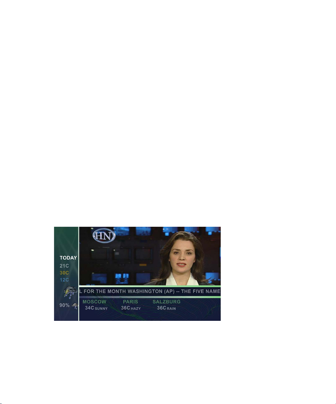
For example, DekoCast lets you create a layout that modifies the studio camera input of a
news anchor with the following additions:
• Crop the anchor video and add a moving background.
• At the bottom of the screen, add a national headline news crawl.
• Add stock quotes and RSS data feeds.
• Add a weather or traffic report graphic that is a looping cel animation or a static graphic.
• Include a time-of-day stamp that loops through each time zone of the region.
22
The following illustration shows an example of a DekoCast layout.
DekoCast makes the design of your layout more flexible by letting you associate objects
with defined areas of the video output frame called target rectangles. When confined to a
target rectangle, objects always display in the same position on the video output, which
allows you to develop one scene for both standard- and high-definition output.
Page 23

DekoCast Products and Applications
Layout with target
rectangles
The following illustration shows the target rectangles used to create the layout in the
preceding example.
For more information, see “Arranging Objects for Video Output” on page 86.
DekoCast Products and Applications
The Avid DekoCast family consists of Avid DekoCast and the Avid DekoCast Authoring
Station. These products are available in three models:
• DekoCast SD (standard definition)
The current version of DekoCast SD ships with the Corsica video board. Older SD
®
systems were shipped with the TARGA
board. There are differences between these
two models. For example, Corsica-based systems use MPEG-2 MXF I-Frame as the
native file format for clip capture and playback, while TARGA-based systems use either
DV 25, MPEG-2 LongGOP, or MPEG-2 I-Frame. Where appropriate, these differences
are described in this guide.Where appropriate, these differences are described in these
Help topics.
• DekoCast HD (high definition)
The current version of DekoCast HD ships with the Corsica video board. Older HD
versions were also shipped with the Corsica board. There is no functional difference
between these models.
• DekoCast SD/HD (hybrid)
DekoCast SD/HD systems allow you to work in either standard definition or high
definition. This model ships with the Corsica video board. For more information, see
“Switching Between Video Formats” on page 29.
23
Page 24

1 Getting Started
Artists can develop on-air edge graphics using either DekoCast or the DekoCast Authoring
Station. The Authoring Station is a fully featured DekoCast system designed for creating
and previewing content, but is not intended for on-air use. (Authoring Station video output is
watermarked.) For information on moving projects from one system to another, see
“Copying Files” on page 42.
The user interface for the DekoCast and DekoCast Authoring Station applications are
n
identical.
Two options are available for DekoCast:
• The Clip Player is an option that provides multi-stream clip playback and storage for
clips. See “Playing Back Clips” on page 140.
• The Cel Animation Player is an option that lets a DekoCast system import and cycle
through a series of numbered image files for animated playout. See “Creating Cel
Animations” on page 173.
The following applications are included with all DekoCast and DekoCast Authoring
systems:
• Avid PostDeko Lite
PostDeko Lite is a full-color video-character generator provided as a graphics creation
tool for DekoCast. Although PostDeko Lite does not support features found in on-air
Deko
of the power of Deko 3000 for building text and graphic layers. Graphic files built in
PostDeko Lite (.dko files) can be used seamlessly in other Deko products (and files built
in Deko products can be used in PostDeko Lite).
®
systems, such as motions, cel animations, effects, and sequences, it does have all
24
PostDeko Lite controls the default directories for the Deko graphics files used by
DekoCast (see “Setting Up Directories” on page 37). For information about using
PostDeko Lite to create content for DekoCast, see the Avid Deko Products User’s Guide,
which is included with your DekoCast documentation.
• Avid DekoCast Central
You can use DekoCast Central as a standalone playout application or in conjunction
with a station’s automation system to control playout of a scene on the on-air DekoCast
system. For more information, see “Using DekoCast Central” on page 351.
• Avid Sequence
The Sequence application controls the playback and timing of actions in scenes without
using or modifying original scenes or actions. For more information, see “Using
Sequence to Play Back Actions” on page 401.
Page 25

DekoCast Workflow
How you integrate DekoCast into your workflow depends on the requirements of your
facility. Here is one typical workflow for creating DekoCast scenes and controlling video
output:
1. Create or otherwise obtain the content for DekoCast source files.
Content includes graphics, animations, clips, and audio. Artists create graphics content
for DekoCast using Deko, PostDeko Lite, or other image-editing applications. You must
use Deko files (.dko) if the text information is to be updated with automation or text
files. Crawls are usually linked to a Deko graphic that contains a text layer. Cel
animations, clips, and audio files are typically created in other programs and linked
within DekoCast.
2. Using an offline DekoCast or DekoCast Authoring Station, assemble a scene, which is
the basic file for DekoCast output.
3. Transfer all of the scene files to the local disk of the on-air DekoCast system. Ensure
that all of the files, file names, and the complete paths for scenes are the same on both
DekoCast systems.
All DekoCast systems in a workflow must be configured to use the same drive structure.
Use drive D for elements, scenes, and graphics that are static images. Use drive E for
clips and audio files. You can save cel animation source files in a directory on either
drive D or E.
DekoCast Workflow
Always copy the DekoCast source files to the on-air DekoCast system’s local disk. A network
n
failure that prevents a DekoCast system’s access to files stored over a network might
interrupt on-air broadcasting.
4. Use DekoCast Central to play the DekoCast scene to air.
25
Page 26
1 Getting Started
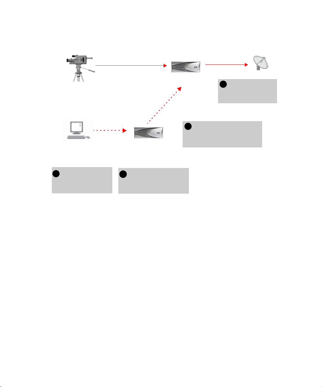
33
Transfer files from the offline
to the on-air system. Make
sure the systems have
matching drive configurations.
2
Use the offline DekoCast
to create a scene and add
graphics to video.
Studio feed
(router)
Video In A
On-air DekoCast system
Use DekoCast
Central to play out
to air
Offline DekoCast
or DekoCast
Authoring Station
PostDeko Lite or other
graphics creation system
1
4
Video Out A
Transfer source
images to the offline
DekoCast system.
The following illustration shows a possible configuration and workflow.
Controlling DekoCast On-Air Video Output
26
There are several ways to control the DekoCast on-air video output:
• Use DekoCast Central, which you can control through a graphical-user interface (GUI)
or by General Purpose Interface (GPI) and Triple i automation. Automation control can
be through RS-232 (COM 1 or COM 2) or RS-422 (COM 3 or COM 4). For more
information, see “Using DekoCast Central” on page 351.
• Use XML to control DekoCast. This involves a user-written or third-party application
that sends XML commands through either a serial connection (COM port) or a network
socket. If you have such an application, specify the COM port or network port used to
send XML commands. For more information, see “XML Configuration” on page 427.
• Use a custom Application Programming Interface (API) developed by third-party
developers. For COM control, use the application API. For serial control, use the Byte
Stream Command Interface (BCI). See the Rocket Engine API documentation and the
Rocket Engine BCI documentation, which are available on the Avid Customer Service
Knowledge Base (www.avid.com/onlinesupport).
Page 27

Before You Begin
• Use the Avid Sequence application to set up a series of actions from scenes whose
playout can be controlled by GPIs. For more information, see “Using Sequence to Play
Back Actions” on page 401.
c
Before running DekoCast on air, close all applications not directly related to on-air
play to conserve resources. If DekoCast is on air, do not use the DekoCast authoring
interface. DekoCast must be offline to preview or add scenes. Close DekoCast before
running DekoCast Central on air.
Before You Begin
Before you start DekoCast, set up your system and install the DekoCast product applications
as described in the Avid On-Air Graphics Setup and Configuration Guide.
Make sure that all DekoCast systems in a workflow are configured to use the same drive
structure. Use drive D for elements, scenes, and graphics that are static images. Use drive E
for clips and audio files. You can save cel animation source files in a folder on either drive D
or drive E. For more information, see “Setting Up Directories” on page 37.
DekoCast operates with Serial Digital Interface (SDI) video. To have video input, your
system needs to be connected to an SDI input device such as a router.
DekoCast does not display any output on your Windows desktop. To view work in progress,
attach a video output monitor to your DekoCast system. Always set your video output
monitor to the underscan setting to prevent peripheral material from being present in the
video output that displays on this monitor.
c
Installing any third-party software on your DekoCast that has not been explicitly
recommended by Avid could void your support agreement. Never install third-party
software without first consulting both the third party and Avid Technology, Broadcast
Support.
Starting and Closing DekoCast Applications
After installation, there are five Avid desktop shortcuts on your desktop: DekoCast,
PostDeko Lite, Sequence, DekoCast Central, and Transcode. Double-click a shortcut to open
its application.
See the Avid On-Air Graphics Setup and Configuration Guide for complete instructions on
n
using the physical components of your system.
27
Page 28

1 Getting Started
To start the DekoCast application:
1. Set the two switches for the dual power supply at the rear of the unit to the On position.
2. Turn on the DekoCast system by pressing the On button on the front of the unit.
3. Log on to Windows XP Professional.
4. Do one of the following:
t Double-click the DekoCast shortcut on the desktop.
t Click the Start button and select All Programs > DekoCast > DekoCast.
The DekoCast main window opens.
If you have a DekoCast SD/HD hybrid system, see “Switching Between Video Formats” on
n
page 29.
To exit the DekoCast application, do one of the following:
t From the menu bar, select File > Exit.
t Click the close button in the main DekoCast window.
When you exit DekoCast, you are prompted to save each scene that you have changed,
one scene at a time.
To start PostDeko Lite, Sequence, DekoCast Central, or Transcode, do one of the
following:
t Double-click the shortcut on the desktop.
t Click the Start button and select All Programs > PostDekoLite > PostDekoLite.
t Click the Start button, select All Programs > DekoCast, and select the appropriate
application.
You can run DekoCast and the other applications simultaneously. Press Alt + Tab to switch
between open applications.
• For information on using PostDeko Lite, see the Avid Deko Products User’s Guide or
the Avid Deko Help.
• For information on using Transcode, see “Transcoding SD Clips to MPEG-2 MXF
I-Frame” on page 149.
• For information on using Sequence, see “Using Sequence to Play Back Actions” on
page 401.
• For information on using DekoCast Central, see “Using DekoCast Central” on
page 351.
28
Page 29

Switching Between Video Formats
If you have a DekoCast SD/HD hybrid system, you can switch from an SD format to an HD
format, or from an HD format to an SD format. For example, you can work in an NTSC
project, and then switch to a 1080i/59.94 HD project.
For more information about available formats, see “Video Hardware Options” on page 416.
To switch from one video format to another:
1. Select Options > Preferences.
2. Click the Video Hardware Options tab.
3. In the Video Format section, select the desired format from the Standard list.
4. If necessary, select the appropriate aspect ratio (4 x 3 or 16 x 9).
5. Click OK.
6. If you are switching from HD to SD, or SD to HD, follow the screen prompts to restart
the application.
Restarting the application is not required when switching between NTSC and PAL or
between HD formats.
Switching Between Video Formats
Configuring Your DekoCast System
Before using your DekoCast system, you need to configure DekoCast for your particular
installation. Configuration includes defining input and output channels and other hardware
settings. For complete information, see “Configuring DekoCast” on page 415.
A DekoCast system has two video input ports. By default, a DekoCast system is configured
for one video input, but you can configure it to have two video inputs, or to have one video
input and one key input.
A DekoCast system is configured by default with one video output. A second video output
port exists that can be configured as a key channel. A DekoCast system is usually installed
downstream of the switcher. When a DekoCast system is installed upstream as a keying
device into the switcher, it must be configured with Output A as the video fill and Output B
as the key signal. Use the Video Hardware Options tab in the Options dialog box to
configure DekoCast’s input and output ports. See “Hardware Configuration Settings” on
page 419.
TARGA-based SD systems support 16-bit audio. Corsica-based SD systems support 20-bit
audio, and Corsica-based HD systems support 24-bit audio.
29
Page 30
1 Getting Started
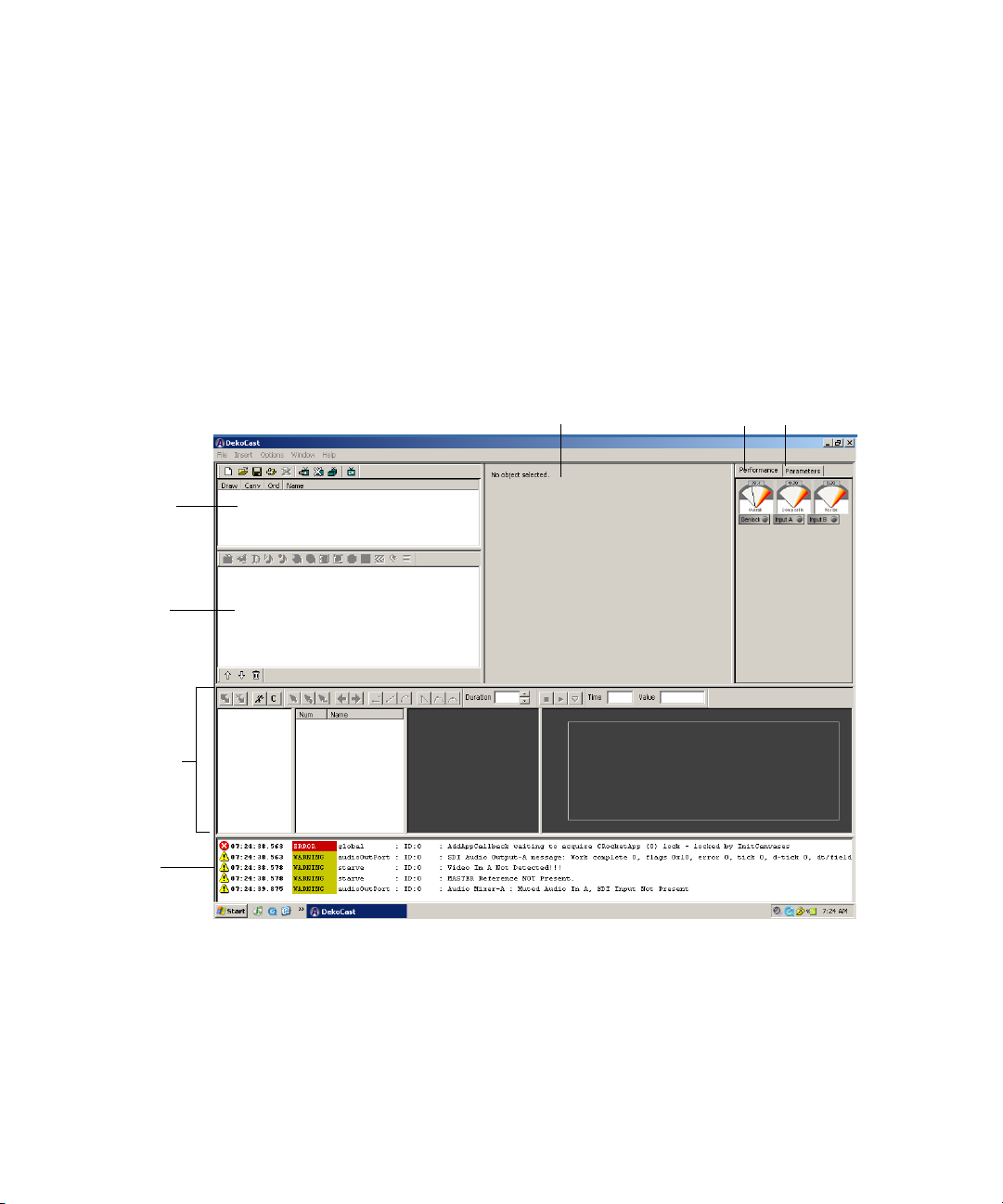
Performance tab
Log pane
Scenes pane
Object pane
Timeline editor
Object Editor pane Parameters tab
Basic Components
This section presents an overview of the most important components of DekoCast. For an
example of how to use these component to build and play out a scene, see “Quick Start:
Fading a Graphic On and Off” on page 45.
DekoCast Main Window
After you start the DekoCast application, the DekoCast main window opens with a set of
empty panes. This window provides the interface for developing DekoCast projects.
30
The major areas (or panes) of the window are the Scenes pane, the Object pane (where the
Scene Tree is displayed), the Object Editor pane, the Timeline editor, and the Log pane. You
can resize each of these panes to suit your current working style by selecting a border of a
pane and dragging it to another position.
Page 31

Scenes
Scenes Pane
Objects in a
Scene tree
Objects Pane
Basic Components
The main organizing tool for creating DekoCast projects is the scene. A scene consists of a
set of objects that you assemble and animate through actions and save as a scene file. The
DekoCast system composites one or more scene files for on-air broadcast.
Scenes are displayed in the Scenes pane.
The Scenes pane includes a toolbar and a shortcut menu that you access by right-clicking the
pane. For more information, see “Working with Scenes and Objects” on page 59.
Objects
Objects are the “actors” that you explicitly add to a scene to perform a task. An object can
represent live video, video clips, audio clips, Deko graphics (either the entire graphic or
selected layers), charts, and cel animations (bugs). When you add an object, it appears in the
Scene Tree in the Objects pane.
You can control an object’s appearance and behavior by changing its properties, such as
scale, position, and opacity (see “Object Editors” on page 33).
31
Page 32

1 Getting Started
Objects
in a
Scene
tree
Objects Pane
Avid does not recommend accessing linked files over a network due to performance
n
variability.
The Objects pane includes a toolbar and a shortcut menu that you access by right-clicking
the pane. For more information, see “Editing Objects in the Scene” on page 79.
The content that you assemble in DekoCast to create projects is developed outside of
DekoCast using PostDeko Lite or third-party graphics applications. For example, a graphic
artist might use Adobe
graphic.You can then use PostDekoLite to create a finished graphic that combines the image
with text, including text that you update in DekoCast through text files or object parameters.
An artist might use Adobe After Effects
animation object or a video clip to be linked to a clip object. You can use Digidesign
Pro Tools
You link source files to objects through file selections you make in the object editor. For
information about supported file types, see “Supported File Formats” on page 41.
Scene Tree
Objects in the Scene Tree are organized hierarchically in a tree structure. The position of an
object in the tree determines the order in which the application draws it for video output. The
application composites the objects in the Scene Tree object-by-object, from the top of the
tree downward, and displays them as video output. The lowest object in the tree is processed
last (and appears in front of all other objects). For more information, see “How Objects Are
Composited” on page 72.
®
Photoshop® to create a static image file to use in a Deko
®
to create audio clips.
®
to create a series of images to be linked to a cel
®
32
Page 33

According to how you arrange objects within the tree hierarchy, objects can function as
Object editor for Cel Animation object (Bug)
Linked file
Tabs
independent objects, as parent objects with child objects, or as child objects under the
control of a parent object. Individual objects that are combined into a group object are child
objects of the group. Groups can be nested within other groups. See “Using Group Objects”
on page 181.
Object Editors
When you select an object, its object editor displays to the right of the Scene Tree. Each
object type has its own editor. Using the editor, you link an object, such as a Deko graphic or
clip, to its source file on your hard drive. The editor also allows you to configure parameters,
which control the object’s behavior, such as its position on video output, scale, opacity, and
playback commands. Each object type has its own set of parameters. Select each tab in an
object editor to view the controls that you can set for that object.
Basic Components
For more information, see “Editing Objects in the Scene” on page 79.
33
Page 34

1 Getting Started
Action list Action Parameter list Timeline Bar editor
Timeline graph
Keyframes
Actions and the Timeline Editor
Scenes are animated through actions, which are recorded changes in object parameters over
time, such as an object’s position, size, and opacity. Actions can turn clips on and off, start
and stop cel animations (bugs), and squeeze back a video input frame. Any parameter value
that can be changed is a potential action, and an action can control multiple parameters. You
can define any number of actions for a scene. Actions allow you to control multiple
parameters simultaneously in a user-definable order.
The Timeline editor has four sections: the Action list, the Action Parameter list, the Timeline
Bar editor, and the Timeline graph. The Timeline editor includes a toolbar. The Action list
and Action Parameter list include shortcut menus that you access by right-clicking within
the list.
You animate actions using the keyframe-based Timeline graph. You can set the parameters
for an action to occur at beginning and ending points (keyframes) on the Timeline graph. You
can also add keyframes and set parameters at any other point on the Timeline graph.
For more information, see “Adding Actions to a Scene” on page 297.
Performance Tab
The Performance tab gives you an overview of the state of the application’s current
processing through a set of three meters (one set for each installed video board).
• The Overall meter measures total system performance.
• The Composite meter measures layer-by-layer compositing of objects in the Scene Tree.
• The Resize meter measures the amount of resources DekoCast utilizes as it resizes an
object, such as the resizing required to create a squeeze-back.
34
Page 35

Basic Components
Green = Source available
Parameters tab showing
Opacity parameters in a scene
Deko Object editor with Opacity parameter
While the application processes your work, pay attention to the meters. Video processing
resources have been exceeded when the meters enter the red zone. As you develop scenes,
Avid recommends not exceeding 80 percent on any meter. Otherwise, you might be
exceeding the system’s processing capability, which could compromise your output.
Lights below the meters indicate whether a source is present for Genlock, Input A and B, or
Audio A and B. A green light means that the source is available. If the light is not green, the
source is not available.
The Performance tab and the Parameters tab share the same pane in the upper-right corner of
the DekoCast window. Click the Performance tab to bring the tab to the front.
Parameters Tab
The Parameters tab consolidates the scene’s parameter data. It lists parameters and their
values for the currently selected scene, the objects within that scene, and installed video
boards. You can search for parameters, change their values, and even define your user
parameters to expedite scene creation. For information on how to use the Parameters tab, see
“Working with Parameters” on page 335.
35
Page 36

1 Getting Started
The Performance tab and the Parameters tab share the same pane in the upper-right corner of
the DekoCast window. Click the Parameters tab to bring the tab to the front.
c
After you are finished using the Parameters tab, click the Performance tab. Keeping
the Parameters tab displayed might slow down updating of the user interface for a
large scene.
Log Pane
System-generated information about DekoCast’s activity displays in the Log pane of the
DekoCast window. You can set the severity level of the information to be recorded in this
log. In certain cases, DekoCast might generate many warnings that are insignificant.
To restrict logging messages:
1. Select Options > Preferences.
2. Change the minimum logging severity level from Warning to Severe.
For more information, see “Application Options” on page 428.
To hide the Log pane, click the lower border of the Timeline Editor window and drag it over
n
the log pane.
Adjusting the DekoCast Window
You can adjust the DekoCast window for your current tasks. For example, if you are working
exclusively in the Timeline editor, you might increase its size and reduce the size of other
panes. You can adjust and save up to three custom window layouts (Layout 1, 2, and 3).
Layouts persist after you exit the application.
To save a custom layout:
1. Open the layout you want to save by selecting Window > Layout x.
2. Resize the DekoCast main window’s panes as you desire.
The layout is associated with the currently selected layout (1, 2, or 3) and remains the
same until you change it.
36
Page 37

To switch to a different layout:
t Select Window > Layout x.
To return all layouts to their default configuration:
t Select Window > Reset to Default.
Online Help
DekoCast includes online Help. The Help is a searchable, hypertext version of this guide, the
Avid DekoCast Products User’s Guide.
To view online Help for DekoCast:
1. Do one of the following:
t Select Help > DekoCast Help.
t Press F1.
2. Use the Contents, Search, or Index tab to find the information you need.
For complete information on using Help, including options for Search, see “Using Help” in
the DekoCast Help.
Understanding Files and File Types
Understanding Files and File Types
This section describes the application’s file types and file-naming conventions. It also covers
steps to take when copying files from one DekoCast system to another. When you transfer
files from an Authoring Station to an on-air DekoCast system, all of the scene’s source files
must be copied to the local disk of the on-air DekoCast system.
Setting Up Directories
The DekoCast system includes two physical drives. As shipped, one drive has two partitions:
C: System and D: Graphics. The other drive has a single partition: E: Clips. These partitions
function as drives.
Avid recommends that you organize your files in directories and save them to the following
drives:
• Drive C: All applications.
• Drive D: DekoCast projects and all static components and elements.
• Drive E: All clips and audio files.
You can save cel animation source files in a directory on either drive D or drive E.
n
37
Page 38

1 Getting Started
You need to make sure PostDeko Lite and DekoCast use the same directories. If the
applications are on different machines, the paths need to match. The default directories that
you set in PostDeko Lite are used by DekoCast to process Deko graphics and all components
of Deko graphics. The PostDeko Lite application defines the default directories in DekoCast
for these kinds of files:
• Graphics and automation
• Styles, preset styles, and shaders
•Macros
• Custom typeface files
Avid recommends that you use the same directory for all types of Deko files and their
n
components. If you use many custom typefaces, you might want to set up a separate
directory for custom typefaces.
To set the default directories in PostDeko Lite:
1. Start PostDeko Lite.
2. Select Options > Preferences.
3. Click the Paths tab.
In the current directory text box, type the complete path for the directory, such as
D:\Dekographics or D:\News. This is the directory where this file type is automatically
saved.
If you need to set up a directory for custom typefaces, do not use a space or an underscore in
n
the name. Use the same custom typefaces directory for all projects at the same location.
38
Page 39

Understanding Files and File Types
Search path
Current directory
If DekoCast fails to find a graphic by searching the path listed in the Current Directory,
it searches the paths listed in the Search Path.
4. In the Search Path text box, type one or more additional paths where DekoCast can
search for the file. Type the complete path and include semicolons to separate multiple
search paths; for example: D:\Deko; E:\DekoBugs.
If DekoCast opens a file from the search path, that search path becomes the Current
Directory.
5. To save changes, select Options > Save Settings Now.
6. Click OK.
If a graphic does not appear in the scene, make sure the graphic and its components are
n
saved in the default directories. Open the graphic in PostDeko Lite and check where it is
saved.
If a scene opens with a letter where you expected to see an image, check the Custom
Typefaces path.
39
Page 40

1 Getting Started
Scene Files
A scene file is saved with all its objects, links to files associated with objects, and animated
actions in the DKX file format.
Prior to DekoCast 4.0, DekoCast scene files were binary files with the DKC format.
Although you can open these older files, you must save them in the DKX format to take
advantage of DekoCast’s newest features. By default, DekoCast saves DKC files as DKX
files but does not modify the previous DKC file.
When prompted to delete the DKC version of the file, click Yes. Avid recommends that you
delete DKC versions of files that were saved as DKX files to avoid having two versions of
the same file.
After you have upgraded a scene to the newer format, the scene is not compatible with
n
earlier versions.
If you open a scene that references files that the application cannot find, it prompts you to
search or browse for them. After you select a folder, the application searches this folder for
any other missing scene files.
c
If your facility has more than one DekoCast or DekoCast Authoring station, Avid
recommends that you upgrade all units to DekoCast 4.0 simultaneously. Also upgrade
all scenes to the DKX format in all online and offline directories.
DekoCast Central supports DKX and the older DKC format.
40
Page 41

Understanding Files and File Types
Supported File Formats
DekoCast supports specific file formats for specific objects. You can view the supported file
formats for an object after you click the Browse button to navigate to a file. Supported file
formats are listed in the Select File dialog box’s “Files of type” menu. The supported source
file formats for objects are listed in the following table.
Supported File Formats
Object Type Supported Formats Requirements
Clip Capture and Clip Playback
SD video clip files
(TARGA
Clip Capture and Clip Playback
SD and HD video clip files
(Corsica systems)
®
systems)
AVI, DV, and DIF
MXF
MXF MPEG-2 4:2:0
DV 25 compression
DV 25
MPEG-2 4:2:0
MPEG-2 4:2:2
I-Frame or IBP compression
MPEG-2 4:2:2 (playback only)
I-Frame compression
You can convert clips to
n
these supported formats
with the Transcode feature
(see “Transcoding SD
Clips to MPEG-2 MXF
I-Frame” on page 149).
Clip Capture and Clip Playback
Key video clip files Same as for Clip Playback video objects
Audio Capture and Playback:
Audio files WAV
AVI (playback only)
Cel animation Usually a series of TGA or TIF files. Other
supported formats are AVI, BMP, DIB, G
(Avid Thunder format), GIF, JPG, PCD,
PCT, PSD, and SGI.
48khz, 16-bit stereo
41
Page 42

1 Getting Started
Supported File Formats (Continued)
Object Type Supported Formats Requirements
Deko DKO, AUT, and ATX
Key: Deko and PostDeko Lite accept static
images with key from other graphics
applications in the following formats: TIF,
TGA, PICT, and PSD.
Full-screen image formats (no key): JPG,
BMP, PCD, G (Avid Thunder format),
PCS, WMF, DIB, RLE, PCT, and PNG. To
use these formats, open the file in
PostDeko Lite and save it as a Deko
(*.dko) graphic.
Text Data TXT, AUT, and ATX
Frame Grab TGA
Copying Files
42
You can develop DekoCast scenes using a different DekoCast system than the one that plays
scenes on air. In this case, ensure that all of the scene’s source files have been copied to the
local disk of the on-air DekoCast system. The file names and complete path for scenes
should be the same on the authoring system and the on-air system.
You need to update all of the asset files on all DekoCast systems. Be aware, however, that
one asset type—the Deko graphic—might contain many related files. The PostDeko Lite
application provides a way for you to copy all of the components of a Deko graphic, as long
as all components reside in the same directory.
If you have a Deko graphic in a scene that
uses textures, macros, and custom typefaces, you must copy all reference, source, or
component files, such as source texture files and source text files (TXT), and save them on
the alternate DekoCast system with the identical directory structures and file names.
Page 43

Understanding Files and File Types
To copy all the components of a Deko graphic from PostDeko Lite:
1. Open PostDeko Lite and select Files > Copy File.
To copy the contents of a folder, select Files > Copy Directories.
n
2. In the Source pane, click Add and select one or more Deko graphics.
3. In the Target pane, click Select and navigate to the Target directory where you want the
files copied.
43
Page 44

1 Getting Started
4. Select the options that you want:
- Select “Append full source path” if you want the source folder structure recreated in
the target directory.
- Select “Copy related files” to copy all files that are associated with the graphic.
- Select an overwrite option.
5. Click Copy to copy all the components of a Deko graphic to the target directory.
TrueType fonts are not included in the Copy File feature. In PostDeko Lite, select
n
File > Information, and open the graphic. A macro window opens that displays which
TrueType fonts are used. You need to copy these fonts manually.
Alternatively, you can examine a Deko graphic layer-by-layer in PostDeko Lite to determine
its components and manually copy those components.
Viewing Information About Your DekoCast System
To view information about your DekoCast system:
t Select Help > About DekoCast.
44
The “Enabled Options” line indicates which options are installed on your system. The Clip
Player and Cel Animation Player are optional features and must be purchased for DekoCast
systems (see “DekoCast Products and Applications” on page 23).
The HASP ID number is the number of your application key (dongle).
Page 45

Quick Start: Fading a Graphic On and Off
The System Information pane indicates how much CPU memory is installed, how much
space is available on drive C, and the largest amount of contiguous video memory (free
chunk of memory, in megabytes) available on the video board.
To view your system’s configuration settings:
t Select Options > Preferences.
If necessary, ask your video engineer to select the correct video format and other
settings, as described in “Configuring DekoCast” on page 415.
Quick Start: Fading a Graphic On and Off
This section takes you step-by-step through the process of creating a simple scene. You’ll be
adding two objects to your scene:
• A Video In object for a studio feed
• A Deko object linked to a Deko graphic
You’ll also be creating two actions:
• Fading a graphic on
• Fading a graphic off
A typical application of this type of scene is displaying a station ID.
Before You Begin
This example requires a graphic that has already been created in a graphics program such as
PostDeko Lite. An ideal graphic would be a station logo that appears a corner of the screen,
but if necessary you can use any type of image.
This scene also requires a video input into your DekoCast system for the Video In object,
such as a studio feed. If you don’t have access to a studio feed, the background appears
black.
New DekoCast systems are supplied with sample scenes and media. See “Using the Sample
n
Scenes and Media” on page 57.
45
Page 46

1 Getting Started
New button
Draw box
Video Out
object
Creating a Scene
Start by creating a scene, which is the basic file for DekoCast output. For information about
scenes, see “Working with Scenes and Objects” on page 59.
To create a new scene:
1. Do one of the following:
t Select File > New.
t Click the New button in the toolbar.
A new, untitled scene appears in the Scene Pane. Notice the draw box and the Video Out
object, which are added by default.
The draw box is selected (checked) by default. If the draw box is selected, your scene
can be played out through your Video Out channel. The Video Out object enables all
other objects in the scene to play out. There is only one Video Out object in a scene. The
Video Out object is the top of your Object Tree.
2. Do one of the following:
t Select File > Save.
t Click the Save icon.
3. Navigate to a folder, type a name for your scene (for example, MyScene), and click
Save.
46
Page 47

Quick Start: Fading a Graphic On and Off
Video In
icon
Object
tree
Object editor and
Name field
The scene is saved as MyScene.dkx. The extension .dkx indicates a DekoCast scene file.
c
DekoCast does not include an Undo, so save early and save often.
Adding Objects
Now that you’ve created a scene, you can add objects to it. In this example, you will add a
Video In object (a studio feed) and a Deko object (a graphic). For more information about
objects, see “Editing Objects in the Scene” on page 79.
To add objects to your scene:
1. Click the Video Out object that appears in the Object Tree to select it.
2. Click the Video In icon to add a Video In object to the Object Tree.
Notice that the Video In object appears indented from the Video Out object, which
indicates that it is a child of the Video Out object. This relationship is required so that
the Video In object plays out to air.
47
Page 48

1 Getting Started
Deko
object
Object editor and
Name field
Browse button
If video is physically connected to an input on your DekoCast system, it should now be
playing full screen through DekoCast to the Video Out channel and should be displayed
on your video output monitor. It does not appear on your computer monitor.
3. Select the Video In object.
The object editor now displays parameters for the Video In object. There are multiple
tabs that organize the types of parameters.
4. Select the Name field at the top of the object editor and type “Studio Feed.”
It’s a good idea to always name objects in a meaningful way.
5. Select the Video Out object.
6. Click the Deko object icon in the toolbar.
DekoCast adds the Deko object to the Object Tree. The object editor now reflects
parameters for a Deko object.
7. In the object editor, rename the Deko object “Static Deko Graphic.”
48
8. In the object editor, click the Browse button and navigate to the graphic file you want to
add to a scene.
This graphic could be a static station ID that was created in PostDeko Lite or in Deko.
See “Before You Begin” on page 45.
Page 49

9. Click Open.
Linked
file
Selected
layer list
The Deko object is now linked to the Deko graphic.
Quick Start: Fading a Graphic On and Off
You should see the graphic on your video output monitor, on top of the video feed. The
following illustration is an example of a station ID on top of a video feed.
If you are using a full-screen graphic without an alpha channel, the graphic might
n
completely cover the video feed. You can crop the graphic as described in the next step.
49
Page 50

1 Getting Started
Cropping
parameter
labels
Notice that Entire Graphic is selected in the Selected Layer list of the Deko object
editor. If a graphic is created with layers, you can select individual layers, which results
in more efficient processing. Processing an entire screen of pixels can take a lot of
system resources, so in this example you can save processing power by cropping.
10. If necessary, click the Position tab of the Deko object editor and use the Cropping
controls to remove the unused part of the graphic.
Use the thumbwheels or type a number so that you remove blank parts of the graphic
while keeping the image itself visible.
The controls are based on an X/Y grid, with dimensions based on the video format. For
example, in NTSC, the full screen width is 720 pixels, so a Left crop of 360 crops off
everything from the middle of the screen to the left edge. To return to the default setting,
click the parameter label.
11. (Option) If you want to change the position or scale of the graphic, use the Position and
Scale controls.
12. Select the Deko object (named Static Deko Graphic) in the Scene Tree.
50
Page 51

13. In the object editor, click the Deko tab and locate the Opacity parameter.
Opacity
parameter
Create Action
button
Animate
Mode button
You’ll be creating an action for this parameter. Drag the arrow back and forth between 0 (no
opacity) and 1 (completely opaque) to view how this parameter changes the graphic.
Adding Actions
Now that you have your objects, you need to animate them by adding actions to the scene. In
this example, you will create two actions in the Timeline editor. For more information about
actions, see “Adding Actions to a Scene” on page 297.
Quick Start: Fading a Graphic On and Off
To add actions to your scene:
1. Add an action by clicking the Create Action button on the Timeline editor toolbar.
A new action appears in the Actions List.
2. Rename the action Fade ON by pressing F2 or right-clicking and selecting Rename.
Now that you’ve created an action, associate it with an object and change the
parameters. You do this by entering Animate mode.
51
Page 52

1 Getting Started
Animate Mode
button selected
Duration: 2
seconds
Timeline graph: Scrub
bar at 0 seconds
3. Click the Animate Mode button on the Timeline editor toolbar.
The icon on the Animate Mode button resembles a running man. When the Animate
Mode button is selected (depressed), you are in Animate mode.
Animate mode creates keyframes for every parameter that you select while you are in this
mode. The time value (the time when the keyframe plays in the action) is determined by the
placement of the Scrub bar. The Scrub bar defaults to the first keyframe with all new actions.
c
52
Keep the Animate Mode button selected only when necessary. Any parameters you
click or select are recorded in Animate mode.
4. In the Timeline graph, make sure the scrub bar is all the way to the left (0 seconds).
Positioning the scrub bar at 0 seconds lets you create a keyframe at the beginning of the
action. The Duration box shows that the action is 2 seconds long. This duration is also
shown on the X axis of the Timeline graph.
Page 53

Quick Start: Fading a Graphic On and Off
Opacity parameter in the
Action Parameter list.
5. Select the Static Deko Graphic object. In the object editor, drag the Opacity slider all the
way to the left, or type 0.00 in the object editor’s Opacity field.
With Opacity set to 0, the graphic is not visible. Notice how the parameter is added to
the Action Parameter list. The name of the parameter is the object name plus the type
of parameter.
6. Create a final keyframe by dragging the scrub bar all the way to the right and setting the
Opacity level at 1.00 (drag the slider all the way to the right or type 1.00).
You now have a complete action that fades the graphic on. Select the parameter in the
Action Parameter list to view a graphical representation of the action: a graphic
changing from not visible to completely visible over 2 seconds.
If more than one parameter appears in your Action Parameter list, you accidently created
n
parameters by clicking in the object editor. Delete all but the Opacity parameter by
right-clicking the parameter and selecting Delete.
53
Page 54

1 Getting Started
7. Preview the action by selecting the Action in the Action list and pressing the space bar.
You should see the graphic fade up in the video output monitor.
Now create another action that fades down the graphic. Remember that you’re still in
Animate mode (the Animate Mode button is selected), so be careful to click or select
only the parameters you want to record. If you create an extra parameter, you can always
delete it.
8. To create a new action, click the Create Action button.
9. Rename the second action Fade OFF.
10. In the Timeline graph, make sure the Scrub bar is all the way to the left (0 seconds, the
default). Drag the Opacity slider to 1 (100% opacity), or type 100 in the Opacity field, or
click the Opacity label to reset it to the default (1). The graphic should be completely
visible on your video output.
11. Create a final keyframe by dragging the scrub bar all the way to the right and setting the
Opacity level at 0 (drag the slider all the way to the left or type 0).
You now have two complete actions: one that fades the graphic on and one that fades the
graphic off.
54
12. Preview the Fade OFF action.
13. Click the Animate Mode button to leave Animate mode.
Remember to deselect the Animate Mode button after creating parameters for an action.
14. Save the scene.
Page 55

Playing the Scene in DekoCast Central
Preset Scene button
You can use DekoCast Central to play the actions. For more information about playout and
DekoCast Central, see “Using DekoCast Central” on page 351. These instructions describe
the basics of playing actions in the Graphical User Interface (GUI).
To load a scene and play an action:
1. Do one of the following:
t Double-click the DekoCast Central desktop icon.
t Click the Start button and select All Programs > DekoCast > DekoCast Central.
The DekoCast Central application opens. The following illustration shows the GUI.
Quick Start: Fading a Graphic On and Off
2. If the GUI is not displayed, select View > Graphical User Interface.
55
Page 56

1 Getting Started
Scene buttons
3. Assign your scene to a Preset Scene button by doing one of the following:
- Right-click the Preset Scene button and select Assign Scene from the menu.
- Select Preset Scenes > Assign Scene.
4. In the Assign DekoCast Scene files dialog box, navigate to the scene you created.
5. Click Open.
The scene is listed on the Scene button you selected.
6. Click the Scene button.
The button turns red and a button is displayed for each action in the scene.
56
Page 57

Using the Sample Scenes and Media
7. Click the Fade ON button to play the action, then left-click the Fade OFF button.
You’ve now completed the Quick Start. The following chapters provide detailed conceptual
information and step-by-step instructions for using DekoCast.
Using the Sample Scenes and Media
New DekoCast systems are shipped with sample scenes and media in the following
locations:
• D:\DekoCast4.0\Finance (graphics, scenes, text files)
• E:\DekoCast_Media (audio, cel animations, clips)
If your system includes this material, you can use it explore the capabilities of DekoCast. If
you are new to DekoCast, consider completing the Quick Start before using the sample
material. As you learn more about DekoCast, you can use the sample material to understand
how particular features can be implemented.
57
Page 58

1 Getting Started
Several versions of the sample scene are included with the installed material. Select the
video format that is appropriate for your system.
To play a sample scene:
1. Select File > Open or click the Open button and navigate to the following folder:
D:\DekoCast4.0\Finance
2. Select a scene in the appropriate video format (for example,
Test_PowerFinance_1080i5994.dkx).
3. In the Scene pane, check the Draw box.
Because of the way the scene is created, you need to play an action to see the
components of the scene.
4. In the Actions pane, double-click the “On” action.
The scene should resemble the following illustration. If your system is configured for a
video input, the video appears in the upper left area.
58
5. Explore the various objects in the scene tree and how they appear in the scene.
6. To stop the action, double-click “Off.”
Page 59

Chapter 2
Scenes toolbar
New scene
Saved scene with
Draw box
selected for video
output.
2 Working with Scenes and Objects
A scene consists of objects, such as passthrough video, Avid Deko graphics, animated logos,
and internal video clips that you organize in a Scene Tree. You then animate the objects by
creating actions that modify the object’s parameters.
The following topics provide basic information about how to work with scenes and objects:
• Scenes Pane and Toolbar
• Creating a New Scene
• Renaming and Saving a Scene
• Opening an Existing Scene
• Working with Objects
• Working with the Scene Tree
• Selecting Scenes for Output
• Multiple Scenes and Stacking Order
Scenes Pane and Toolbar
The Scenes pane is the area of the DekoCast window in which you organize DekoCast
scenes for a project. As you create new scenes and open existing ones, they are listed in the
Scenes pane.
Page 60

2 Working with Scenes and Objects
New
Open
Save
Save As
Close
Show Scene
Change Scene
Order
Hide Scene
Exclusive Show Scene
Scenes are listed in the Scenes pane by name. A new scene is named UntitledAPI (API
stands for Application Program Interface) and numbered according to the number of scenes
you have added during the DekoCast session. You can rename a scene only when you save it.
The Scenes pane includes four columns:
• Draw: The Draw box determines if a scene is played to video output. See “Selecting
Scenes for Output” on page 75.
• Canv (Canvas): The Canvas number indicates which video board is being used for
processing. Currently shipping systems include only one video board.
• Ord (Order): The Order number determines the order in which multiple scenes are
processed. See “Multiple Scenes and Stacking Order” on page 76.
• Name: The default filename or the complete file path for a saved scene.
The Scenes pane has its own toolbar and shortcut menu.
60
The New Scene, Open Scene, Save Scene, Save As Scene, and Close Scene tools have
equivalent commands in the main File menu. The Show Scene, Hide Scene, Change Scene
Order, and Exclusive Show Scene tools can be accessed only through their toolbar buttons.
To display a brief description of a tool, move the mouse pointer over its button without
n
clicking.
The shortcut menu commands are New (Insert), Open (Ctrl+O), Close (Del), and Save
(Ctrl+S). Select a scene in the Scenes pane and right-click it to display this menu.
Scenes that you have created using the DekoCast application appear in the Scenes pane in
black typeface. The Scenes pane also contains scenes that are open in DekoCast Central.
These names are italicized and in blue typeface.
Scenes created through another program, such as a program developed using the Application
Programming Interface (API), also appear in blue italics. If you modify scenes not created in
DekoCast, save them with another name using the Save As command before closing the
Page 61

scene to avoid changing the original scene file. When you rename a scene, DekoCast
New
scene with
Draw box
selected
for video
output.
Video Out
object
Video Out object editor
considers it created in DekoCast, and when you reopen it, the renamed scene appears in the
list in black typeface
Creating a New Scene
To create a new scene, do one of the following:
t Select File > New.
t Click the New icon in the Scene Pane toolbar.
Creating a New Scene
After DekoCast creates a new scene, the following changes appear in the DekoCast window:
• A new, untitled scene is added to the Scenes pane. Scenes that you add during a
DekoCast session are named sequentially. New scenes that you add to the Scene Tree
are always selected to be drawn to video output (the scene’s Draw box is selected).
• A Video Out object is added to the Object pane. When you create a scene, it
automatically has video output associated with it.
Video output is required if the result of your DekoCast scene is to be output to a monitor
or played to air. DekoCast draws changes you make to this scene in real-time and can
display them on a video output monitor.
• The Video Out object editor is displayed. Object editors allow you to control an object’s
parameters. The Video Out object editor lets you select the port and adjust the video
frame’s background color and opacity.
61
Page 62

2 Working with Scenes and Objects
For more information about the Video Out object editor, see “Editing Video Out Objects” on
page 81.
When creating scenes, pay attention to the Performance meters in the upper-right corner of
n
the DekoCast window (see “Performance Tab” on page 34). Video processing resources
have been exceeded when the meters enter the red zone. As you develop scenes, try not to
exceed 80 percent on any of the meters. See “DekoCast Tips” on page 435 for suggestions
on the most efficient use of system resources.
Renaming and Saving a Scene
To rename a scene, you need to save it with a new name.
To rename a scene:
1. Do one of the following:
t Select File > Save As.
t Click the Save As button.
The Save As dialog box opens.
2. Navigate to the directory where you want to save the scene, type a new name, and click
Save.
62
c
By default, DekoCast scene files are saved as DKX files in the directory in which you last
opened or saved a scene.
To save a scene:
1. Select File > Save.
If the scene has not yet been saved, the Save As dialog box opens.
2. Navigate to the directory where you want to save the scene, type a name, and click Save.
Save your work frequently to avoid losing any part of your project. DekoCast does not
have an autosave feature or an undo function.
To close a DekoCast scene:
1. Select the scene.
2. Do one of the following:
t Select File > Close.
t Click the Close button on the Scenes Pane toolbar.
You are prompted to save any changes.
Page 63

Although you can modify scenes created in other applications (their names appear in the
New scene
Saved scene with
Draw box
selected for video
output.
n
Scenes list in italics and blue typeface), you must save them with another file name using the
Save As command. See “Scenes Pane and Toolbar” on page 59.
Opening an Existing Scene
A scene always opens in the state in which it was last saved or closed.
An existing scene file that you open is not automatically enabled. After adding an existing
scene to the Scenes pane, select its Draw box to have DekoCast draw the scene to video
output.
Opening an Existing Scene
DekoCast scenes are saved as DKX files. Although you can open older DKC files, you must
save them in the DKX format to take advantage of DekoCast’s newest features. DekoCast
automatically adds the .dkx extension when you attempt to save an older DKC file. When
prompted to delete the DKC version of the file, click Yes.
Avid recommends that you delete DKC versions of files that were saved as DKX files to avoid
n
having two versions of the same file.
To open an existing scene:
1. Do one of the following:
t Select File > Open.
t Click the Open icon on the Scenes Pane toolbar.
2. Navigate to the file you want to open and click Open.
The scene is added to the Scenes pane.
63
Page 64

2 Working with Scenes and Objects
Objects in a
Scene Tree
Object editor
Object
toolbar
Working with Objects
A scene can have any number of objects. Depending on how you arrange objects within the
tree hierarchy, objects can function as independent objects, parent or group objects with
child objects, or child objects under the control of a parent or group object. The arrangement
of objects in a scene is called a Scene Tree.
The following topics describe how to add objects to a Scene Tree and provide basic
information about objects. Additional information about the Scene Tree is provided in
“Working with the Scene Tree” on page 70.
Adding Objects to the Scene Tree
A new scene always begins with a Video Out object. When you create a scene, a Video Out
object labeled Video Out 1 is automatically added to the Scene Tree. As you build your
scene, you add other objects to the Scene Tree.
64
Page 65

Working with Objects
Video Out
Video In
Deko
Object
Text Data
Crawl
VBI
Object
Plug-in
Cel
Animation
Group
Frame
Grab
Clip
Capture
Clip
Playback
Audio
Playback
Audio
Capture
Chart
Newly added objects are placed as the last object in the Scene Tree list unless you select an
object in the Scene Tree before adding an object. In this case, the new object is placed
directly below the selected object. In this way the new object becomes a child of the parent
object.
To add an object to the Scene Tree:
1. If you want to add an object as a child, select the parent object.
For example, select the Video Out object before adding a Video In object. Some objects
cannot be added as children. See “Understanding Parent-Child Relationships” on
page 74.
2. Do one of the following:
t Select the object from the Insert menu.
t Click the object’s icon in the Object toolbar.
n
n
To display a brief description of a tool, hold the cursor over its button without clicking.
When you add an object to the Scene Tree, the application assigns it a default name,
ending in a number, starting at 1. You should rename objects appropriately as described
in “” on page 66.
If you are adding a Deko object, you need to decide which method to use: adding it from the
Insert menu or adding it from the Object toolbar. The method you choose determines the
characteristics of the Deko object. For more information, see “Adding a Deko Object to a
Scene” on page 109.
65
Page 66

2 Working with Scenes and Objects
Objects Overview
This topic provides a brief description of each of the application objects. Detailed
information about working with an object are provided in “Editing Objects in the Scene” on
page 79. A specific cross-reference is provided for each of the objects.
Object Icon Object Name Description
Video Out A Video Out object makes a composite of objects placed
Video In A Video In object takes live video from a physical input port
beneath it in the Scene Tree and sends the result to a video
output port. Everything that is placed below a Video Out object
is layered as a single SDI video signal (with encoded audio).
If you delete the Video Out object, its child objects remain in
the Scene Tree but cannot can be drawn to output. See “Editing
Video Out Objects” on page 79.
and passes it to Video Out. It also patches and mixes the
embedded audio present at the input port. Your system should
have its Video Input port connected to a device with an SDI
feed such as a router. Although you can add multiple Video In
objects to the Scene Tree, video input functioning is
determined by the number of actual video input ports that the
system supports.
You must explicitly add a Video In object to the Scene Tree.
Using the Video In object editor, you can position, crop,
change the opacity, and scale the Video In signal. The
application also provides level and routing controls for audio
embedded in the video. See “Editing Video In Objects” on
page 83.
66
Page 67

Object Icon Object Name Description
Deko Deko objects include text and graphic elements generated in
PostDeko Lite or other applications. These graphics can have
borders, drop shadows, extrusions, kerning and leading, and
textures. The Deko object’s editor allows you to control cuts
and dissolves between text fields, and to roll and crawl text
fields.
You can import a Deko graphic object as an entire Deko
graphic (the layers are flattened into a single layer), a single
layer, or instruct the application to create a separate Deko
object for each layer in the graphic.
The text displayed in a Deko object can be changed at any
time, independent of other scene elements. You can edit Deko
objects within a scene by opening their files in PostDeko Lite
and saving them with the same file name. See “Working with
Deko Objects” on page 110.
Working with Objects
Audio Playback
The application recognizes WAV and AVI files as source
files for Audio Playback objects. After you select an
audio file, it plays back from the system’s hard drive.
Playback controls allow you to queue, play, and stop the
audio file, either manually or through actions that you
define in the Timeline Editor. See “Playing Back Audio”
on page 136.
Audio Capture The Audio Capture object records audio and saves it to files in
the WAV format. See “Capturing Audio” on page 137.
Clip Playback Clip Playback (available with the Clip Player option)
With the Clip Playback object, you can use internally stored
video clips with associated key files in much the same way as
Video In. See “Playing Back Clips” on page 139.
Clip Capture The Clip Capture object encodes video and writes the encoded
stream with audio to the hard disk. After you record clips, you
can play them back using the Clip Player. See “Capturing
Clips” on page 161.
67
Page 68

2 Working with Scenes and Objects
Object Icon Object Name Description
Cel Animation Cel Animation (available with the Cel Animation Player
Group Group objects are collections of other objects. By grouping
option)
A Cel Animation object, sometimes called a bug, consists of a
series of similar images, each with a slightly different
orientation. When played back in rapid succession, these
images create the illusion of motion. The application reads the
first file in the series and continues loading files until it
encounters a break in the numbering sequence.
Because of the amount of video processing resources required
to process a cel animation, smaller cel animations are
preferable to larger ones. Pay attention to the Performance
meters when working with cel animations. See “Creating Cel
Animations” on page 169 and “DekoCast Tips” on page 429.
objects, you can set parameters and actions that affect the
entire group and continue to work with each object separately.
For example: A scene includes text that crawls over a banner
and a logo. With the Group object selected, add three Deko
objects to the group—one for the banner layer, one for the text
layer, and one for the logo graphic layer. Then you can assign
the Group object a position, opacity, and actions that affect all
three Deko objects. See “Using Group Objects” on page 177.
68
Frame Grab The Frame Grab object can capture one or more images from a
video source and saves each image, or frame, as a TARGA
(TGA) file. See “Capturing Video Images (Frame Grab)” on
page 183.
VBI The VBI (Vertical Blanking Interval) object extracts timecode
and closed-caption data, making it available to API clients to
trigger events based on time codes or command streams
contained in closed-caption data. See “Working with VBI
Objects” on page 186.
You need to include a VBI object in your scene only if
n
your installation has a special program that can use this
data.
Crawl A Crawl object moves a continuous stream of text, cel
animations, or clips from one side of the output frame to the
other, or for a roll, from the bottom to the top of the output
frame. A crawl object can also include audio playback. See
“Creating Crawls” on page 190.
Page 69

Object Icon Object Name Description
Renaming Objects
Working with Objects
Plug-Ins These are special utilities provided by Avid and third parties
that add functionality to the application. See “Adding Plug-in
Objects” on page 217.
Text Data A Text Data object, which is automatically added when you
add a Crawl object, can read plain text, AUT, and ATX files to
drive crawls. This object includes rules that you set to
determine how non-text objects are inserted between lines of
text in crawls. Source text files can include programming tags
to control how DekoCast formats the text and how non-text
objects are inserted between lines of text. See “Creating
Crawls” on page 190.
Do not add Text Data as a separate object.
n
Chart Chart objects are charts that are created by using the Chart
Designer.
See “Working with Charts and Graphs” on page 219.
When you add an object to the Scene Tree, the application assigns it a default name that ends
in a number. For example, a new scene always begins with a Video Out object, which the
application adds automatically as the first item in the Scene Tree. The first Video Out object
you add after launching the application is labeled Video Out 1. Every time you create a new
scene in the session, the number is incremented by one. To avoid being confused by a scene
that begins with an object named Video Out 4 or Video Out 7, specify an appropriate name
for each object.
An object’s name should reflect its object type and be as specific as possible. For example, if
you are adding multiple Crawl objects, the first might be lower third crawl and the second
coming_up_next. When working with a multiple-layer Deko graphic, your naming scheme
might be as follows: bar yellow L3, bar thin white, bkg photo, crawl text, headline text, and
image for OTS. Assign descriptive names for audio files and clips, such as jungle audio,
purple swirl clip, or purple clip for L3.
To rename an object in the Scene Tree:
t Edit the name in the object editor’s Name text box.
The name you use is a descriptive name for your organizational purposes only, and can
contain any characters.
When editing a text box, press the Esc key if you need to cancel your changes.
n
69
Page 70

2 Working with Scenes and Objects
Delete
Branch
expanded with
children visible
Branch
collapsed
To better distinguish between objects and groups in Action parameters, use lower-case
n
letters for object names and capital letters for group names.
Working with the Scene Tree
The following topics describe how to build and use the Scene Tree as part of your scene.
Expanding or Collapsing a Branch
Adding objects as children of a parent object creates a child-parent branch in the Scene Tree.
Objects in the Scene Tree that are preceded by a plus or minus sign can be expanded or
collapsed. Collapsing a branch you are not working with provides a better view of other
objects in the Scene Tree.
70
To expand a branch:
t Click the plus sign (+).
All children of the parent object are displayed.
To collapse a branch:
t Click the minus sign (–).
Only the parent object is visible.
Page 71

Deleting Objects
To delete an object from the Scene Tree:
t Select it and click the Trash icon at the bottom of the Object pane.
Deleting a collapsed parent object deletes all of its child objects. Deleting a Group
object deletes all of the children within the group. If you delete a Video Out object,
every child object associated with it no longer appears in the video output.
Inserting a Scene within a Scene Tree
If you have created scenes that you want to combine into a single scene, you can insert the
scenes into an existing scene.
To insert a DekoCast scene:
1. Select the location in the Scene Tree for the new scene.
If the scene to be inserted does not have a Video Out object at the top of its own Scene
Tree hierarchy, it is inserted in the current scene under the currently selected object.
Otherwise, it is inserted as a separate scene at the bottom of the Scene Tree.
2. Select Insert > Scene.
Working with the Scene Tree
The Open dialog box opens.
3. Select an existing DekoCast scene file (.dkx).
4. Click Open.
An entire DekoCast scene, including objects, along with their parameters, hierarchical
order, and actions, is added to the Scene Tree in the selected location.
71
Page 72

2 Working with Scenes and Objects
Objects are
composited from
the top of a Scene
Tree downwa rd .
The object at the
bottom of the tree
appears on top in
the video output
How Objects Are Composited
DekoCast composites the objects in the Scene Tree object-by-object, from the top of the tree
downward, with the last object appearing on top in the video output. This last object has
priority in the Scene Tree. When positioning objects in the Scene Tree, visualize how the
application prioritizes each object and how one object affects all other objects.
The following illustration shows a Scene Tree with various objects arranged in priority
order, with the object at the bottom of the tree appearing on top in the video output.
n
n
72
The position of objects in the Scene Tree determines how the objects are displayed in the
video output. When a Video In object (Router In), which is full-frame, is placed below the
Video Out object, it completely fills the video output. Therefore, any image in the Video Out
object is completely covered and cannot be viewed. Then, because a full-frame Clip
Playback object (Background) has a higher priority, it completely obscures the Video In
object. For at least part of both objects to be visible simultaneously, you must position, scale,
crop, or make transparent the topmost object in the Scene Tree.
The Position tab in the object editor provides controls for cropping visible objects. A visible
object is an object that is drawn to video output.
In this example, a Cel Animation object (Bug) is the topmost object and has the highest
priority. When the application composites the scene, the bug overlays all of the other objects,
but covers only a small part of the video output in the upper-left corner—not the full frame.
How the application prioritizes objects becomes apparent when you add objects to a Scene
Tree and observe the results on a video output monitor.
You can bring a Deko graphic into the application with layers or flattened to one layer.
When you add the Deko object to a Scene Tree, the application composites a Deko graphic
layer the same as it does any other layer.
Page 73

Understanding Grouped Objects
Group objects are
composited from the top
of a group downward
Group object (parent)
Last child in Group (In a
Wipe this object obscures
child objects above it.)
First child in Group
Objects that you organize into groups within the Scene Tree are composited from the top of
the group downward. This processing order works the same way for objects in groups as it
does for objects in a Scene Tree. The last object in a group, which appears at the bottom of
the group, appears on top of the other objects in the video output.
Groups have parental status while objects under the control of a group are its children.
Grouping enables you to set parameters for a set of objects as if they were a single object,
but you must consider how the application layers each of the group’s component objects.
Working with the Scene Tree
Rearranging Objects in the Scene Tree
Information about working with Group objects is provided in “Using Group Objects” on
page 181.
You might need to rearrange the priority of objects in the Scene Tree to produce the desired
video output. The bottom object in a Scene Tree or group appears on top of those above it in
the video output.
To rearrange objects in the Scene Tree, do one of the following:
t Right-click an object in the Scene Tree and select Copy. Position the cursor in another
location, right-click, and select Paste. If you want to delete the object you copied, select
the object and click the Trash icon.
t Select a child object and drag it to another parent object. You can also select a group
object and drag it (and its children) onto a Group object, which then becomes its parent.
73
Page 74

2 Working with Scenes and Objects
Move
object
up
Move
object
down
t Select the object and click the Up or Down Arrow buttons at the bottom of the Scenes
pane window.
You can move objects (or groups) to other positions in the tree hierarchy and place them as
children of parent objects as long as the object is capable of serving in that role. If it is not, a
message informs you that the object cannot be a parent or child for the specified object and
you are not allowed to insert it.
Understanding Parent-Child Relationships
A scene’s objects are organized hierarchically in the Scene Tree. Within the tree, an object
might be a separate object, a parent object with children, or the child of a parent object. The
application prevents you from setting up parent-child relationships that are not allowed.
The following rules apply to parent-child relationships in the Scene Tree:
• A Video Out object is the parent object for all other play-to-air objects in the Scene
Tree. It is required for video output of its child objects. Any object other than objects
that record input must be a child of a Video Out object in order to be displayed.
• The objects that record input — Video Out, Clip Capture, Audio Capture, and Frame
Grab — are root objects and can have no parents.
• Only Video Out, Group, Crawl, and Text Data objects can have children.
• If you delete a collapsed parent object in the Scene Tree, all of its children are also
deleted.
• Groups have parental status while objects under the control of a group are its children.
74
Page 75

Opacity levels for child objects are determined by their parent’s opacity level. For
Draw box
selected
Show Scene
Hide Scene
Exclusive Show Scene
example, if a child object has 50 percent opacity and its parent has 50 percent opacity,
then the child object’s opacity is 25 percent (half that of its parent).
Selecting Scenes for Output
Several DekoCast scenes can be open simultaneously, and some, all, or none of them can be
active on the outputs simultaneously. Scenes whose Draw boxes are selected (checked) are
active. When you add a new scene, its Draw box is selected automatically.
Selecting Scenes for Output
To select a scene for video output:
t Select the scene’s Draw box.
To remove a scene from video output:
t Deselect the scene’s Draw box.
You can also use the Show Scene and Hide Scene tools in the Scene toolbar to select and
n
remove scenes.
To set one scene as the exclusive scene for output:
t Select the scene and click the Exclusive Show Scene tool in the Scene toolbar. The
selected scene is selected for drawing and the others are removed from output (and
deselected).
The Exclusive Show Scene tool switches between being active and inactive. When it is
active, only one scene (the last one you checked) is active. Click the tool again to allow
multiple scenes to be selected as active scenes for output.
75
Page 76

2 Working with Scenes and Objects
Processed first
Processed last
(highest priority)
Change Scene Order
Multiple Scenes and Stacking Order
DekoCast gives you the option of using a single scene or multiple scenes.
A typical project consists of a single scene. If you work with multiple scenes, be aware that
n
each scene is independent. You cannot control one scene from another scene without using
an API program developed for that purpose.
The Order (shown in the Ord column) refers to the stack order for video processing and
video output. The stacking order is important only if your project contains multiple scenes,
and then only when the video output for a scene overlays another scene.
When DekoCast processes multiple scenes, it places scenes in a buffer queue and draws
them according to their assigned stack number, beginning with the highest number and
ending with the lowest number. For example, for scenes assigned stack number 1, 2, and 3,
the scene assigned as stack number 3 (the highest number) is placed first in the queue for
processing. The scene assigned stack number 2 is placed directly behind stack number 3 in
the queue and is processed next. The scene assigned stack number 1 (the lowest number) is
placed last in the queue, following the other two scenes. This final scene, which has the
highest priority, appears on top in the video output.
The following illustration shows this stacking order and priority.
To display objects in scenes that overlay other scenes, turn off the Background of the Video
Out object for all scenes except the scene with the highest order number (see “Editing Video
Out Objects” on page 81.
If you have multiple scenes for output, you must set the stack order for each scene.
n
Otherwise DekoCast draws the scenes in a random order and then outputs the drawn scene
to video.
76
Page 77

To set the stack order for a scene:
1. Select the scene in the list.
2. Click the Change Scene Order tool on the Scenes toolbar.
3. Enter the new number, and click OK.
Multiple Scenes and Stacking Order
c
Scenes stacked in the queue might consume resources even if they are inactive. For
example, if a clip associated with an inactive scene in the stack is running, the codec is
in use and not available to the active scene as it is being drawn to video output. When
working with multiple scenes, consider how all scenes interact. Try to ensure that
active scenes have sufficient resources.
77
Page 78

2 Working with Scenes and Objects
78
Page 79

Chapter 3
3 Editing Objects in the Scene
Each object type has an object editor that allows you to view and edit its properties, which
are called parameters. Actions that you create using the Timeline editor reflect changes
made to an object’s parameters.
The following topics describe how to edit objects in the scene:
• Using an Object Editor
• Editing Video Out Objects
• Editing Video In Objects
• Using the Target and Position Tabs
• Using the Levels and Mixer Tabs
• Working with Deko Objects
• Playing Back Audio
• Capturing Audio
• Playing Back Clips
• Capturing Clips
• Creating Cel Animations
• Using Group Objects
• Capturing Video Images (Frame Grab)
• Working with VBI Objects
• Creating Crawls
• Adding Plug-in Objects
• Working with Charts and Graphs
Page 80

3 Editing Objects in the Scene
Video
Out
object
Video Out Object editor
Using an Object Editor
Each object is associated with an editor, as shown in the following illustration. The object’s
editor opens whenever you select an object in a Scene Tree or add an object to it. The
following illustration shows the Video Out object and the Video Out Object editor.
80
An object editor includes settings, filenames, and other properties that define the object.
These properties are referred to as an object’s parameters. You animate an object by creating
actions that control the object’s parameters, as described in “Adding Actions to a Scene” on
page 297.
You can also use the Parameters tab to modify parameters. See “Working with Parameters”
n
on page 335.
Page 81

Editing Video Out Objects
Video Out
button
When you create a new scene, the Video Out object is added as the first object in the Scene
Tree. A DekoCast system has one video output. You can, however, set up a second video
output for a key signal. When a DekoCast system is installed upstream as a keying device
into the switcher, it must be configured with Output A as the video fill and Output B as the
key signal.
Use the Video Hardware Options tab in the Options dialog box to configure DekoCast’s
n
input and output ports. See “Video Hardware Options” on page 416.
To specify a video output port:
t Select a port from the Video Output Port menu:
- For video only, select Video Out A.
- For key signal only, select Video Out B.
Editing Video Out Objects
The Video Out editor also allows you to control the opacity, color, and transparency of areas
of the video frame that are not covered by objects.
Setting Background Color and Opacity
You can select a color for the background of a scene. This is useful if you do not have
Video In input into your device and need to view an object that includes black, such as a
black banner of a Deko object. Because the default background is black, the black banner
will be invisible unless you have video coming in or the Background turned on. You can turn
the Background on, change it to a color other than black, and use it for testing. A
Background matte set to a color is not recommended for use on air.
81
Page 82

3 Editing Objects in the Scene
When the Background is set to On, the color of the background behind the objects in a scene
is controlled by the Red, Green, and Blue sliders on the Video Output object editor. If the
system is configured with a key output, then the value of the key signal is controlled by the
Alpha slider. A typical scene has a single Video Out object.
On a Corsica-based system, the Red, Green, and Blue background colors are multiplied by
n
the value of the Alpha slider to determine the background color. You need to set a value for
the alpha even if the video output is not configured for key.
Any Video Out objects lower in the bottom-to-top compositing order are obscured by the
Background. This situation might occur if you are combining multiple scenes (see “Multiple
Scenes and Stacking Order” on page 76.
When the Background is set to Off, the Red, Green, Blue, and Alpha sliders have no effect,
and the background is black.
To set the background color and opacity:
1. In the Background section of the Video Out object editor, select On.
2. Click a color slider and drag it to change the selected color from full transparency (0.00)
to full opacity (1.00).
Any background color you select is displayed in the adjacent color rectangle.
To preview the output on a Corsica based system, drag the Alpha slider to a value other
than 0.
3. (Option) Click and drag other color sliders to blend the background color.
If Red, Green, and Blue are set to 1.00, the background is white. If set to 0.00, the
background is black. If Red and Green are set to 1.00 and Blue is set to 0.00, the
background is yellow. The individual values for Red, Green, and Blue can vary from
0.00 to 1.00.
To set the value of the key signal:
t Adjust the Alpha slider.
Selecting a Custom Background Color
You can use the color palette to select a custom color for the background opacity.
Custom Colors are remembered within your current session only.
n
82
Page 83

To select a custom color:
Color chip
Color Spectrum
Value Spectrum
Luminance slider
Drag the pointer
to change hue
1. In the Video Out object editor, click the color rectangle.
The color palette opens.
Editing Video Out Objects
2. Do one of the following:
t Select one of the color chips
t Click a hue in the Color Spectrum.
t Drag the pointer in the Color Spectrum.
3. To change the color’s value (relative darkness or lightness), select and drag the
Luminance slider.
4. Click OK.
When Luminance is set to 0, which is black, dragging the Luminance Slider upward displays
n
lighter colors.
To modify a value using the keyboard:
t Edit the values for the Hue, Sat (Saturation), Lum (Luminance), or Red, Green, and
Blue text boxes and click OK.
To add a new color for this session only:
t Adjust the color using the Color Spectrum and Value Spectrum controls, then click Add
to Custom Colors and click OK.
Your currently selected color is displayed in the Color/Solid area.
83
Page 84

3 Editing Objects in the Scene
Video In
button
Editing Video In Objects
The Video In object editor allows you to select the video input port, set the opacity of the
video input, and define video input key information.
The Video In object editor has the following tabs: Video, Position, Target, Levels, and
Mixer. Only the Video tab is unique to the Video In object.
The Target and Position tabs, which enable you to position and size objects for video output,
are the same for all objects that the application draws to video output. All audio-related
objects share the Levels and Mixer tabs. For instructions on using the Position and Target
tabs, see “Using the Target and Position Tabs” on page 86. For instructions on using the
Levels and Mixer tabs, see “Using the Levels and Mixer Tabs” on page 103.
When the scene is used upstream from a switcher, do not add a Video Input object to the
n
Scene Tree. The Video Input key is a full-raster key that prevents objects underneath the
Video Input object from being drawn to output.
Selecting a Video Input Port
A DekoCast system has two video input ports. By default, a system is configured for one
video input, in the Video Hardware Options tab (see “Video Hardware Options” on
page 416). You can configure it to have two video inputs (such as a facility feed and video
from a server), or to have one video input and one key input. Use the Video Hardware
Options tab to configure the DekoCast system’s input ports. To use two video inputs, you
need to add two Video In objects to the Scene Tree and select a different port for each.
84
Page 85

To select a video input port:
t In the Video Input object editor, select a port from the Video Input Port menu:
- For video input only, select Video In A.
- For a second video input, or for a key input, select Video In B.
You might need to author and transfer a scene to a different system in which Input B has
been enabled and set as key, even though your system is not configured for video key input.
In this case, you can select an option while authoring a scene so that the your system
discards the video input key information. Deselect this option before you transfer the scene.
To have the application discard key information while authoring:
t Select the Ignore Key option.
To add the key information before transferring:
t Deselect the Ignore Key option.
Changing the Opacity of a Video Input Object
Editing Video In Objects
c
You might want to set the opacity of a Video Input object, for example, when creating an
action to fade in the video.
To change the opacity of a video input object:
t In the Video Input object editor, drag the Opacity slider to vary the Video In object’s
opacity from full transparency (0.00) to full opacity (1.00).
As of the DekoCast 4.0 release, you have to explicitly add a Video In object to the Scene
Tre e.
85
Page 86

3 Editing Objects in the Scene
News Anchor
(Video In object)
Movie Credits
(Clip object)
Using the Target and Position Tabs
The Target and Position tabs are common to most visible objects, that is, objects the
application draws to video output. These objects include Video In, Deko, Clip Playback, Cel
Animation, and Group.
The Target and Position tabs are related, but have different functions. These functions are
described in the following topics:
• “Arranging Objects for Video Output” on page 86
• “Using Screen Coordinates” on page 87
• “Using Thumbwheel Controls” on page 88
• “Using the Target Tab” on page 89
• “Using The Position Tab” on page 95
• “Designing Your Layout” on page 96
Arranging Objects for Video Output
By default, DekoCast aligns the top-left corner of most visible objects with the top-left
corner (0,0) of the video output frame. (The exception is the Crawl object, which by default
is placed in the lower portion of the video output.) You can change this default behavior by
using the Position and Target tabs in the object editor to position objects anywhere on the
video output frame.
86
Use of the Position and Target tabs is optional. If you do not apply either tab, the entire
n
object is displayed as normal size and placed in its default location.
Avid recommends that you use the Target tab to arrange objects for video output. By using
the Target tab, you can associate an object with a defined area of the video frame called a
target rectangle. For example, to have movie credits play alongside local news teasers,
define a target rectangle for a Clip object (movie credits) on one side of the output frame and
define a target rectangle for the source Video In object (news feed) on the other side.
Page 87

Using the Target and Position Tabs
The purpose of using target rectangles is to create scenes in an aspect ratio that is
video-resolution independent. By using target rectangles to scale and align elements in a
scene, you can create a scene in 16:9 SD and it will be ready to air from a 16:9 HD system.
If you use the Position tab to scale and align elements in a scene, you must recreate the scene
for playing out at a different video resolution.
Using target rectangles does not allow scenes built in one aspect ratio to work in another.
n
For example, a 16:9 SD scene converts well to a 16:9 HD scene, but a 4:3 SD scene does not
convert well to a 16:9 HD scene.
For information about creating target rectangles, see “Using the Target Tab” on page 89. For
examples of how to use target rectangles in a page layout, see “Designing Your Layout” on
page 96.
If you link a Deko object to one or more layers in a graphic, and you want to control a
n
layer’s position with a target rectangle, you must select Layer as the Layout option in the
Deko object editor. See “Guidelines for Adding Deko Objects” on page 113.
Another advantage to using target rectangles is that you can prevent overlapping objects,
because the objects are confined to the corresponding target rectangles.
Both the Target tab and the Position tab allow you to scale an object and to change its default
position for video output. However, you can crop an image only in the Position tab. The
application applies parameters set by the Position tab to an object after it applies any
parameters set by the Target tab. After defining a target rectangle for an object, you can use
the Position tab to fine-tune the scale and position of the entire target rectangle, and crop it.
Scenes that are built with only Position parameters are still valid, and you can continue to
n
build scenes using only the Position tab. If you import scene files with only Position
parameters, you can either use these parameters or define new target rectangles.
Using Screen Coordinates
Both the Position tab and the Target tab use the X- and Y- coordinates of the screen. When
you place an object using Position tab parameters, you use X- and Y- coordinates to identify
the object’s position on the video output. However, when you place an object using Target
tab parameters, you use the coordinates to identify the target rectangle’s position. Then the
object’s position on video output is defined in relation to its target rectangle’s top, bottom,
left, and right coordinates.
The default coordinates used by both tabs are determined by the video standard. For
example, the X-coordinates for Standard Definition NTSC range from left (0) to right (720),
and the Y-coordinates range from top (0) to bottom (487).
87
Page 88

3 Editing Objects in the Scene
0,0
Default point of origin
0,720
0,487
Type a value in text box and
press Enter.
Click the text label
to return to the
default value.
Select and drag
thumbwheel.
By default, screen coordinates are set with 0, 0 as the top left corner. To revise these
n
coordinates, select Options > Preferences and click the Coordinates tab. See “Output Frame
Coordinates” on page 429.
Using Thumbwheel Controls
The Target and Position tabs have thumbwheel controls that use screen coordinates to
determine position. You select and drag to define values for an object or a target rectangle.
This example shows the thumbwheel controls for defining a target rectangle.
88
Use the thumbwheels in the following ways:
• To make coarse adjustments, hold down the Shift key while dragging a thumbwheel to
the right or left. To make fine adjustments, hold down the Ctrl key while dragging.
• Type an integer or decimal number in the text box to the right of a thumbwheel and
press Enter.
• To revert to a thumbwheel’s default value, click the text description to the left of the
thumbwheel. For example, to return to the default target rectangle parameters (full
screen), click the text that reads Left, Top, Right, or Bottom.
• To revert to the default target rectangle full-screen coordinates, click the Reset button.
Page 89

You can disable rounding to whole pixels through the App Options tab. Select Preferences >
0,0
The entire output
frame is the default
target rectangle
A defined target
rectangle is a
subdivision of the
output frame
Default point of origin
n
Options and click the App Options tab. See “Application Options” on page 428.
Using the Target Tab
Visible objects are objects that the application draws to video output, such as the Deko, Clip
Playback, and Cel Animation objects. A visible object’s editor includes a Target tab, which
enables you to define the location and size of an object’s target rectangle. You then specify
how the object is to be placed on the video output in relation to its target rectangle.
The purpose of using target rectangles is to create scenes in an aspect ratio that is
video-resolution independent. See “Arranging Objects for Video Output” on page 86.
Use of an object’s Target tab is optional. If you do not want to define a rectangular area of
n
the video frame for an object, select Disable in the Target tab.
Defining a Target Rectangle
The application places most visible objects in the upper-left corner of the video output,
where the X and Y coordinates are 0,0. Using a target rectangle lets you specify how the
object is to be placed on the video output in relation to the target rectangle. The following
illustration shows the default target rectangle and a smaller target rectangle you could define.
Using the Target and Position Tabs
To practice using a target rectangle, add a visible object such as Video In or a Deko object to
n
the Scene Tree and work with its Target tab while reading these instructions.
89
Page 90

3 Editing Objects in the Scene
Reset button
Coordinates of target
rectangle
Locked
option
Autoscale
option
To define a target rectangle for a visible object in a scene:
1. Select the object’s Target tab in the object editor.
90
2. Make sure the Disable option is not selected if you want to define a target rectangle.
3. Select and drag the Left, Top, Right, and Bottom thumbwheels to define the position of
the target rectangle on the video output, or enter coordinate values that define it.
As you change target rectangle coordinates, the current positions display in real time in
the upper right of the tab. You can always click the Reset button to return to the default
target rectangle value, which is full screen.
For information on using the thumbwheels, see “Using Thumbwheel Controls” on
page 88.
4. (Option) Select and drag the X and Y Position thumbwheel controls to move the center
of the rectangle to the right and left on the X-axis, or up and down on the Y-axis.
5. (Option) Select and drag the Width and Height thumbwheels to resize the target
rectangle.
You cannot change the Width and Height of a target rectangle whose Autoscale option is set
n
to None, which means that the target rectangle is to always maintain its original size.
Page 91

6. To maintain a desired aspect ratio between width and height, select the Locked option.
7. Set the Autoscale parameters that tell the application how to place the object in relation
to the target rectangle:
- None: Maintains the object’s original size while being aligned horizontally and
vertically in respect to the target rectangle. If you select None, you must also select
the horizontal and vertical alignment for the target rectangle.
- Fit: Stretches the object to fill the entire rectangle. (The object’s aspect ratio is lost.)
- Preserve: Maintains the object’s aspect ratio in respect to its the target rectangle:
inside (minimum), outside (maximum), horizontally, or vertically.
See the diagrams for these three parameters in the next topic.
Scaling an Object in Relation to Its Target Rectangle
The following diagrams show the placement of objects in relation to target rectangles when
you select None, Fit, or Preserve as the Autoscale option.
Using the Target and Position Tabs
91
Page 92

3 Editing Objects in the Scene
Object
Horizontal Alignment: Left
Vertical Alignment: Top
Object maintains size and is
aligned in left, top of target.
Object maintains size and is
aligned at right, center of target.
Object maintains size and is
aligned at center in the center
of the target.
Horizontal Alignment: Right
Vertical Alignment: Center
Horizontal Alignment: Center
Vertical Alignment: Center
Autoscale: None
Target Rectangle of Any Size
None
The None Autoscale option maintains the original size of an object and lets you choose how
to align it in its target rectangle:
• Select Left, Right, or Center as its Align Horizontal option.
• Select Top, Bottom, or Center as its Align Vertical option.
92
Page 93

Using the Target and Position Tabs
Object
Object stretched to fully
cover Target Rectangle
Target Rectangle of Any Size
Autoscale: FIt
Fit
The Fit Autoscale option maps the object entirely onto the target rectangle without
preserving the aspect ratio of the object. The object is stretched to fully fill the target
rectangle, regardless of the size of the object.
Preserve
The Preserve Autoscale option resizes the object without changing its aspect ratio. When
you select Preserve, specify where the object is to be placed in relation to the target rectangle
by selecting one of four Autoscale options:
• Minimum: Maps the object onto a destination that is completely contained by the target
rectangle.
• Maximum: Maps the object onto a destination that completely covers the target
rectangle.
• Horizontal: Maps the object’s left and right edges onto the target rectangle’s left and
right edges, scaling the object vertically to preserve the aspect ratio.
• Vertical: Maps the object’s top and bottom edges onto the target rectangle’s top and
bottom edges, scaling the object horizontally to preserve the aspect ratio.
93
Page 94

3 Editing Objects in the Scene
Target Rectangle of Any Size
Object
Preserve Minimum:
Horizontal Alignment: Center
Vertical Alignment:
Not Applicable (N/A)
Object scaled to fit inside of
target. Aspect ratio maintained.
Centered.
Autoscale Preserve: Minimum and Maximum Options
Preserve Minimum:
Horizontal Alignment: Left
Vertical Alignment: N/A
Object scaled to fit inside of
target. Aspect ratio maintained.
Left alignment.
Preserve Maximum:
Horizontal Alignment: N/A
Vertical Alignment: Top
Object scaled to cover target.
Aspect ratio maintained.
Top alignment.
Preserve Maximum:
Horizontal Alignment: N/A
Vertical Alignment: Center
Object scaled to cover target.
Aspect ratio maintained.
Center alignment.
Target Rectangle
Target Rectangle
After you select a Preserve Autoscale option, you can align the object vertically and
horizontally in relation to the target rectangle, if appropriate.
94
Page 95

Using The Position Tab
X,Y coordinates
Position and
Scale
thumbwheels
Scale values
Using the Position tab, you can change an object’s position to any area of the video output,
scale it relative to its normal size, and crop it. Setting cropping parameters enables you to
control the visible region on which the application draws the object to video output.
When you change an object’s position using the Position tab (as opposed to using the Target
n
tab), the scene that contains the object might not appear the same at different video
resolutions. See “Arranging Objects for Video Output” on page 86.
Using the Target and Position Tabs
The application applies parameters set by the Position tab to an object after it applies any
parameters set by the Target tab. After defining a target rectangle for an object, you can use
the Position tab to fine-tune the scale and position of the entire target rectangle, and crop it.
Changing an Object’s Position and Scale
To change the position of the object:
t In the object editor, select and drag the X or Y thumbwheel to the right or left until the
desired new position is displayed in the text box to the right of the thumbwheel. This
position is relative to the left and right X coordinates and to the top and bottom Y
coordinates.
95
Page 96

3 Editing Objects in the Scene
To change the scale of the object:
t Select and drag one of the following thumbwheels to scale the object:
-Scale
-X Scale
-Y Scale
Drag the thumbwheel to the right or left to attain the desired scale; the value is relative
to a scale of 1, which represents the object’s normal size.
A positive number greater than 1 enlarges the object and a positive number less than 1
reduces its size.
For more information about using thumbwheels, see “Using Screen Coordinates” on
page 87.
Cropping an Object
When you scale a video frame to less than 100 percent, you might see extraneous video or
black around the edges of that frame. The Cropping thumbwheels allow you to eliminate
edges by trimming the top, bottom, and sides of the frame.
To set cropping parameters:
t In the object editor, click and drag the Left, Right, Top, and Bottom thumbwheels until
the desired cropping of the object is obtained.
The controls display a positive number (greater than 0) as you trim towards the center of
the object.
If working with a Deko object that uses the Entire Graphic or is a Background, crop it so
n
that only the desired area is rendered.
Designing Your Layout
Before creating your scene, plan what you want your scene to accomplish and how you want
it to look. Your goal is to design the layout that viewers see on their television screens, which
translates in the application to how objects display on video output. As part of your design
process:
• Consider the object tools that you have to develop a scene. Only visible objects, that is,
objects that the application draws to output, such as Deko, Clip Playback, Cel
Animation, and Video In objects, have object editors with the Position and Target tabs.
The Target tab controls parameters that define the target rectangle.
96
Page 97

Objects that the application does not draw to video output, such as the Frame Grab, have no
n
need to be positioned or placed in target rectangles on the output frame. If an object does
not have Position and Target tabs in its object editor, it is not a visible object.
• How do you want to subdivide the screen into rectangles? For example, you might place
video-in feed in the center, a logo in the upper-right corner, and crawl text scrolling in
the lower third. Each of these divisions is associated with a visible object.
• How do you want to place the object in relation to the rectangle? For example, an object
can be aligned in the exact center of a rectangle while maintaining its aspect ratio, or
stretched to fill the rectangle without keeping its aspect ratio.
• Will the rectangle change dynamically? If you plan to apply an action to create a
squeeze-back, what are the object’s beginning and ending positions? Actions you create
using target rectangles are also independent of resolution and video standard.
Guidelines for Using Target Rectangles
When working with target rectangles, consider the following guidelines:
• When you add a visible object to the Scene Tree, the application displays it in a default
position on the video output. You can do one of the following:
- Leave the object in its default position.
Using the Target and Position Tabs
- Reposition it using the Position tab (not recommended if you want the same scene
to play out at different video resolutions).
- Set up a target rectangle to control where and how the object appears on video
output using the Target tab.
• A target rectangle is associated with a visible object. It does not exist as a rectangle
independent of its object.
• If you link a Deko object to one or more layers in a graphic, and you want to control
their positions with target rectangles, you must select Layer as the Layout option in the
Deko object editor. See “Adding a Deko Object to a Scene” on page 109.
• Group objects can also have target rectangles that apply to the group.
• Only visible objects can have target rectangles. Only object editors for visible objects
have a Target tab.
• The default target rectangle is full screen.
• Each of the four sides (left, top, right, bottom) of the target rectangle is a parameter of
the object.
• If you select Disable in the Target tab, the object has no target rectangle. You can
reposition the object using its Position tab.
97
Page 98

3 Editing Objects in the Scene
• An object is positioned with respect to its target rectangle according to which option
(None, Fit, or Preserve) you select from the Target tab’s Autoscale menu.
- None. The object can maintain its original size (no change = None) while being
aligned horizontally and vertically in respect to the target rectangle. If you select
None, you must also select the horizontal and vertical alignment of the object to the
target rectangle.
- Fit. The object can be stretched to fit the entire rectangle. (The object’s aspect ratio
is lost.)
To better view an object target rectangle’s region on video output, add a background color to
n
the Video Out object, then apply the Fit Autoscale option.
- Preserve. The object can be made to preserve its aspect ratio in respect to its target
rectangle. There are four possible Preserve Autoscale options: Min, Max,
Horizontal, and Vertical.
Select whether the application is to contain the object within the target rectangle
(the Minimum option) while maintaining the object’s aspect ratio, or scale the
object so that it covers the target rectangle (the Maximum option while maintaining
the object’s aspect ratio). The object can be placed within the rectangle horizontally
or vertically. After you assign the Autoscale placement, you can align the object
horizontally (top, bottom, center) and vertically (top, bottom, and center) as
appropriate.
98
See “Scaling an Object in Relation to Its Target Rectangle” on page 91 for diagrams of each
n
Autoscale option.
• A target rectangle has no visible borders. To “see” an object’s target rectangle, set its
Autoscale option to Fit, which causes the object to dynamically fill the rectangle as you
adjust the thumbwheel controls. Observe how the object stretches to fill the target
rectangle and does not maintain its aspect ratio.
• When you define a target rectangle for a group, all of the child objects are encompassed
by it.
Page 99

Suggestions for Preparing Your Layout
News Clip
Object
Logo Cel
Animation Object
News Crawl
Object
News Anchor Video
In Object
Squeeze - End
Rectangle
Squeeze - Start
Rectangle
Sample of a Video Output Frame Segmented Into Target Rectangles for Objects
For a simple layout, such as placing a Cel Animation object in the lower-right corner,
designing “on the fly” using the Target tab is sufficient. For a more complex layout that
requires rectangles of a set size, you might use Deko layers to block out rectangles as you
want them to appear on the video output frame. Keep in mind that each rectangle is
associated with a specific object. A target rectangle has no border lines—its size changes as
you adjust the object’s thumbwheel controls. If you design your layout using a drawing
program, you can open it within the application and use it as a template for “tracing”
rectangles. To make it easier to transfer your layout, assign a different color to each
rectangle.
If you do not use a template file, add a Video Out background color to gauge the rectangle’s
n
boundaries (see “Editing Video Out Objects” on page 81). You can also set the Autoscale
option to Fit to have the object completely fill the rectangle as you adjust it using the
thumbwheel controls.
Using the Target and Position Tabs
You might find it helpful to create a template file in a drawing program other than PostDeko
Lite. In this case, the rectangles must have the same dimensions as you want them to have in
the video output frame. In the drawing program, save the file as a BMP file and link to it as a
Cel Animation object. Be aware that this is not a real Cel Animation object, but a
workaround to use a file created in another drawing program as a template. You have to
delete this Cel Animation object (or clear its file name) before saving the scene. For more
information, see “Defining the Source File for a Cel Animation” on page 175.
99
Page 100

3 Editing Objects in the Scene
Transferring a Layout to a Scene
If you use a graphics tool to design a layout to use as a template, you need to transfer it to a
scene.
To transfer a layout to a scene:
1. Create a new scene.
2. If you created a layout template as a file in PostDeko Lite, add a Deko object and link it
to the file.
If you created a layout in a different graphics program, import it into PostDeko Lite, export
n
it as a .dko file, and link it to a Deko object. You can also import the file directly as a Cel
Animation object (see “Suggestions for Preparing Your Layout” on page 99).
The template file’s rectangular divisions display on the video output. This object’s only
purpose is for layout design. Delete this object after you have finished using it as a
template.
3. Add a visible object to the Scene Tree, such as a Clip Playback, Deko object, or Cel
Animation object.
4. Select the Target tab in the object’s editor, which opens to the right of the Scene Tree.
If you select Disable in the Target tab, a target rectangle cannot be defined.
n
5. (Option) As a means to “see” the target rectangle as you adjust the thumbwheel
controls, set the Autoscale option to Fit.
The Fit option stretches the object to the borders of the rectangle, making it easier to see
the area you are defining. Unless you want the object to fill the rectangle in your actual
scene, however, you need to select one of the other Autoscale options after you have
specified the left, top, right, and bottom coordinates of the target rectangle.
6. Define the target rectangle for the object using its Target tab. See “Example: Defining a
Target Rectangle for Video In” on page 100. Also see, “Using the Target Tab” on
page 89.
7. Add additional visible objects and define their target rectangles.
8. After deleting any object used only for tracing purposes, save the scene.
Example: Defining a Target Rectangle for Video In
In this example, you will define a target rectangle for a Video In feed. You want the target
rectangle to fill the right half of the screen. You want the Video In object to keep its aspect
ratio while filling the width of the target rectangle and aligning with the top of the target
rectangle.
100
 Loading...