

Page 1

DEKOCAST
Technical Reference And Service Guide
Pinnacle® Systems, Inc.
280 N. Bernardo Avenue
Mountain View, CA 94043
July 2004
Copyright© 2004 Pinnacle® Systems, Inc.
P/N 322100119
Rev. A
Page 2

Preface
This manual is a technical reference for the DekoCast workstations. A technical overview for the workstations are
provided, as well as information on troubleshooting a workstation and replacing software and hardware components
within a workstation.
This manual is intended for the person who sets up and uses the DekoCast workstation, and the Pinnacle Systems
Customer Support Engineer who provides technical support for the workstations over the phone.
Important: This manual references only newer DekoCast systems that were shipped after July 2004 and includes the
model numbers listed below:
• Model: 322202000 -- DekoCast
If the model number of your DekoCast system does not appear in the list above, please refer to the Quick Install
document that was provided on the Application CD with the original shipment of your system.
Trademarks
All brand or product names mentioned her e in are used for identification purposes only and may be trademarks or
registered trademarks of their respective companies.
DekoCast Technical Reference And Service Guide
Copyright © 2004 Pinnacle Systems, Inc.
All Rights Reserved.
Reproduction, adaptation, or translation of this document without pri or written permissio n is prohibited, except as
allowed under copyright laws.
Printed in the United States.
Note: The information in this document is subject to change without notice or obligation.
Pinnacle Systems Part #322100119
Revision A
15 July 2004
JML
2 DekoCast Technical Reference And Service Guide
Page 3

Official Notices And Warranties
Software License Agreement
IMPORTANT—READ CAREFULLY: This Software License Agreement is a legal agreement
between You and Pinnacle (or its suppliers). This System contains certain Pinnacle computer
software (“Software”), associated media, printed materials, and electronic documentation. By
using the Software, You agree to be bound by the terms of this Software License Agreement. If
You do not agree to the terms of this Software License Agreement, Pinnacle is unwilling to
license the Software to You. In such case, You may not use or copy the Software. This system
also contains certain third party software, which is provided to You upon the condition that You
agree to the terms outlined in the third party software licenses included with the materials shipped
with the System.
License: Pinnacle grants to You a nonexclusive, personal, perpetual, nontransferable, limited license
to use the installed Software exclusively on hardware on which Pinnacle has loaded the Software, or
other hardware on which Pinnacle has authorized it to be loaded, but solely in connection with the
operation of Your internal business, and not for the benefit of any third party. Such Software may
only be enabled by Pinnacle or its authorized agent. Pinnacle and its licensors retain all right, title and
interest in and to all Software, but title to the media on which the Software is delivered is transferred
to You.
Restrictions: The Software is copyrighted and may contain material that is protected by patent, trade
secret or other laws pertaining to proprietary rights. You may not copy the Software, except that it
may make a single copy for archival purposes. You may not modify the Software or permit or assist
any third party in doing so. You may not decompile, reverse engineer, disassemble, or otherwise
reduce the Software to source code or other human-readable form, or attempt or permit any third party
to do so. Any violation of this Software license shall be a material breach and shall immediately entitle Pinnacle to exercise any remedy that may exist at law or in equity.
Copyright: All title and copyrights in the Software (and any copies thereof) and the accompanying
printed materials are owned by Pinnacle. All rights not specifically granted under this Software
License Agreement are reserved by Pinnacle.
Limited Warranty: Pinnacle warrants that (a) the Software will perform substantially in accordance
with the published specifications for a period of one year
hardware will be free from defects in materials and workmanship under normal use and service for a
period of one year
This warranty will not apply to repair or replacement necessitated by accident, disaster, improper or
inadequate maintenance, customer or customer-supplied interfacing or machines, unauthorized modifications or repairs, improper electrical current, misuse, abuse or improper installation. This warranty
is personal to You and may not be assigned or transferred. Pinnacle does not warrant that the Software will operate error-free.
THE LIMITED WARRANTY SET FORTH HEREIN IS THE ONLY WARRANTY, EXPRESS,
IMPLIED OR STATUTORY THAT PINNACLE MAKES WITH RESPECT TO THE PRODUCTS.
ALL IMPLIED WARRANTIES, INCLUDING, BUT NOT LIMITED TO, THE IMPLIED WARRANTIES OF MERCHANTABILITY, FITNESS FOR A PARTICULAR PURPOSE AND NONINFRINGEMENT, ARE DISCLAIMED.
from the date of receipt.
from the date of receipt and (b) any Pinnacle
DekoCast Technical Reference And Service Guide
3
Page 4

Official Notices And Warranties
Limitation of Liability
PINNACLE SHALL NOT BE LIABLE FOR INDIRECT, SPECIAL, INCIDENTAL, OR
CONSEQUENTIAL DAMAGES; FOR DAMAGES THAT DIRECTLY OR INDIRECTLY
ARISE FROM YOUR USE OF, OR INABILITY TO USE, THE SYSTEM; FOR
COMMERCIAL LOSS OF ANY KIND; FOR THE PROCUREMENT OF SUBSTITUTE
GOODS--WHETHER ARISING IN TORT, CONTRACT OR ANY OTHER LEGAL THEORY,
EVEN IF PINNACLE HAS BEEN ADVISED OF THE POSSIBILITY OF SUCH DAMAGES.
IN ANY EVENT, PINNACLE’S LIABILITY SHALL BE LIMITED TO THE AMOUNT
ACTUALLY PAID BY YOU FOR THE SYSTEM GIVING RISE TO ANY SUCH DAMAGE.
THIS LIMITATION IS INTENDED TO LIMIT PINNACLE’S LIABILITY AND SHALL
APPLY NOTWITHSTANDING ANY FAILURE OF ESSENTIAL PURPOSE OF ANY
LIMITED REMEDY.
4
DekoCast Technical Reference And Service Guide
Page 5

Table of Contents
OFFICIAL NOTICES AND WARRANTIES . . . . . . . . . . . . . . . . . . . . . . . . . . . . . . . . . . . . . . . . . . . . 3
Software License Agreement . . . . . . . . . . . . . . . . . . . . . . . . . . . . . . . . . . . . . . . . . . . . . . . . . 3
Limitation of Liability . . . . . . . . . . . . . . . . . . . . . . . . . . . . . . . . . . . . . . . . . . . . . . . . . . . . . . 4
CHAPTER 1: INTRODUCTION TO DEKOCAST . . . . . . . . . . . . . . . . . . . . . . . . . . . . . . . . . . . . . . . 7
Contents . . . . . . . . . . . . . . . . . . . . . . . . . . . . . . . . . . . . . . . . . . . . . . . . . . . . . . . . . . . . . . . . . . . 7
Introduction . . . . . . . . . . . . . . . . . . . . . . . . . . . . . . . . . . . . . . . . . . . . . . . . . . . . . . . . . . . . . . . 8
Using This Manual . . . . . . . . . . . . . . . . . . . . . . . . . . . . . . . . . . . . . . . . . . . . . . . . . . . . . . . . . 8
CHAPTER 2: DEKOCAST SYSTEM OVERVIEW . . . . . . . . . . . . . . . . . . . . . . . . . . . . . . . . . . . . . . 9
Contents . . . . . . . . . . . . . . . . . . . . . . . . . . . . . . . . . . . . . . . . . . . . . . . . . . . . . . . . . . . . . . . . . . . 9
Hardware Configuration . . . . . . . . . . . . . . . . . . . . . . . . . . . . . . . . . . . . . . . . . . . . . . . . . . . . 10
TARGA 3200 Board . . . . . . . . . . . . . . . . . . . . . . . . . . . . . . . . . . . . . . . . . . . . . . . . . . . . . . . . . . . . . . . . . . . . 10
Daria Bypass Board . . . . . . . . . . . . . . . . . . . . . . . . . . . . . . . . . . . . . . . . . . . . . . . . . . . . . . . . . . . . . . . . . . . . 10
RS-422 Board . . . . . . . . . . . . . . . . . . . . . . . . . . . . . . . . . . . . . . . . . . . . . . . . . . . . . . . . . . . . . . . . . . . . . . . . . 10
Signal Flow . . . . . . . . . . . . . . . . . . . . . . . . . . . . . . . . . . . . . . . . . . . . . . . . . . . . . . . . . . . . . . 11
Workstation Front Panel . . . . . . . . . . . . . . . . . . . . . . . . . . . . . . . . . . . . . . . . . . . . . . . . . . . . 12
Workstation Back Panel . . . . . . . . . . . . . . . . . . . . . . . . . . . . . . . . . . . . . . . . . . . . . . . . . . . . 13
CHAPTER 3: INSTALLATION AND SETUP . . . . . . . . . . . . . . . . . . . . . . . . . . . . . . . . . . . . . . . . . . 15
Contents . . . . . . . . . . . . . . . . . . . . . . . . . . . . . . . . . . . . . . . . . . . . . . . . . . . . . . . . . . . . . . . . . . 15
Unpacking . . . . . . . . . . . . . . . . . . . . . . . . . . . . . . . . . . . . . . . . . . . . . . . . . . . . . . . . . . . . . . . 16
DekoCast Workstation Initial Setup . . . . . . . . . . . . . . . . . . . . . . . . . . . . . . . . . . . . . . . . . . . 17
Repacking A DekoCast Workstation . . . . . . . . . . . . . . . . . . . . . . . . . . . . . . . . . . . . . . . . . . . . . . . . . . . . . . . 20
DekoCast GPI Input Connections . . . . . . . . . . . . . . . . . . . . . . . . . . . . . . . . . . . . . . . . . . . . . 21
DekoCast RS-422 Automation Control . . . . . . . . . . . . . . . . . . . . . . . . . . . . . . . . . . . . . . . . 22
Daria Board Signal Flow . . . . . . . . . . . . . . . . . . . . . . . . . . . . . . . . . . . . . . . . . . . . . . . . . . . 23
Over-Ride Switch Pinouts . . . . . . . . . . . . . . . . . . . . . . . . . . . . . . . . . . . . . . . . . . . . . . . . . . . . . . . . . . . . . . . 24
Network Configuration . . . . . . . . . . . . . . . . . . . . . . . . . . . . . . . . . . . . . . . . . . . . . . . . . . . . . 24
C
HAPTER 4: TROUBLESHOOTING . . . . . . . . . . . . . . . . . . . . . . . . . . . . . . . . . . . . . . . . . . . . . . . 25
Contents . . . . . . . . . . . . . . . . . . . . . . . . . . . . . . . . . . . . . . . . . . . . . . . . . . . . . . . . . . . . . . . . . . 25
I/O Diagnostic Utility . . . . . . . . . . . . . . . . . . . . . . . . . . . . . . . . . . . . . . . . . . . . . . . . . . . . . . 26
Modes Of Operation . . . . . . . . . . . . . . . . . . . . . . . . . . . . . . . . . . . . . . . . . . . . . . . . . . . . . . . . . . . . . . . . . . . . 26
Setup Before Testing . . . . . . . . . . . . . . . . . . . . . . . . . . . . . . . . . . . . . . . . . . . . . . . . . . . . . . . . . . . . . . . . . . . 26
Automatic Test Procedure . . . . . . . . . . . . . . . . . . . . . . . . . . . . . . . . . . . . . . . . . . . . . . . . . . . . . . . . . . . . . . . 27
Manual Test Procedure . . . . . . . . . . . . . . . . . . . . . . . . . . . . . . . . . . . . . . . . . . . . . . . . . . . . . . . . . . . . . . . . . 32
Deko Manifest Utility . . . . . . . . . . . . . . . . . . . . . . . . . . . . . . . . . . . . . . . . . . . . . . . . . . . . . . 37
Deko Manifest Test Procedure . . . . . . . . . . . . . . . . . . . . . . . . . . . . . . . . . . . . . . . . . . . . . . . . . . . . . . . . . . . . 37
Interpreting Deko Manifest Test Results . . . . . . . . . . . . . . . . . . . . . . . . . . . . . . . . . . . . . . . . . . . . . . . . . . . . 40
CHAPTER 5: SYSTEM MAINTENANCE . . . . . . . . . . . . . . . . . . . . . . . . . . . . . . . . . . . . . . . . . . . . 43
Contents . . . . . . . . . . . . . . . . . . . . . . . . . . . . . . . . . . . . . . . . . . . . . . . . . . . . . . . . . . . . . . . . . . 43
Replacing Workstation Components . . . . . . . . . . . . . . . . . . . . . . . . . . . . . . . . . . . . . . . . . . 44
Replacing A TARGA Card . . . . . . . . . . . . . . . . . . . . . . . . . . . . . . . . . . . . . . . . . . . . . . . . . . . . . . . . . . . . . . . 45
DekoCast Technical Reference And Service Guide 5
Page 6

Table Of Contents
Replacing The Daria Bypass Card . . . . . . . . . . . . . . . . . . . . . . . . . . . . . . . . . . . . . . . . . . . . . . . . . . . . . . . . 50
Replacing The RS-422 Card . . . . . . . . . . . . . . . . . . . . . . . . . . . . . . . . . . . . . . . . . . . . . . . . . . . . . . . . . . . . . 53
Replacing The SVGA Card . . . . . . . . . . . . . . . . . . . . . . . . . . . . . . . . . . . . . . . . . . . . . . . . . . . . . . . . . . . . . . 56
Replacing A Hard Drive . . . . . . . . . . . . . . . . . . . . . . . . . . . . . . . . . . . . . . . . . . . . . . . . . . . . . . . . . . . . . . . . . 58
Replacing A Power Supply . . . . . . . . . . . . . . . . . . . . . . . . . . . . . . . . . . . . . . . . . . . . . . . . . . . . . . . . . . . . . . . 61
Replacing The Fan . . . . . . . . . . . . . . . . . . . . . . . . . . . . . . . . . . . . . . . . . . . . . . . . . . . . . . . . . . . . . . . . . . . . . 63
Replacing The DVD/CD Drive And/Or Floppy Drive . . . . . . . . . . . . . . . . . . . . . . . . . . . . . . . . . . . . . . . . . . 66
System Recovery Procedures . . . . . . . . . . . . . . . . . . . . . . . . . . . . . . . . . . . . . . . . . . . . . . . . 71
You Have The Software Disks Supplied By Pinnacle Systems . . . . . . . . . . . . . . . . . . . . . . . . . . . . . . . . . . . . 71
Configuring A Restored DekoCast OS . . . . . . . . . . . . . . . . . . . . . . . . . . . . . . . . . . . . . . . . . . . . . . . . . . . . . . 73
Installing The DekoCast Software . . . . . . . . . . . . . . . . . . . . . . . . . . . . . . . . . . . . . . . . . . . . . . . . . . . . . . . . . 79
Installing The Daria Bypass Card Software . . . . . . . . . . . . . . . . . . . . . . . . . . . . . . . . . . . . . . . . . . . . . . . . . 80
Recreating A DekoCast Drive Image Restore DVD . . . . . . . . . . . . . . . . . . . . . . . . . . . . . . . . . . . . . . . . . . . 81
Configuring A New “System” Hard Drive . . . . . . . . . . . . . . . . . . . . . . . . . . . . . . . . . . . . . . 87
Configuring A New “Media” Hard Drive . . . . . . . . . . . . . . . . . . . . . . . . . . . . . . . . . . . . . . 93
APPENDIX A: PINNACLE SYSTEMS CUSTOMER SUPPORT . . . . . . . . . . . . . . . . . . . . . . . . . . . . 99
About Deko Support . . . . . . . . . . . . . . . . . . . . . . . . . . . . . . . . . . . . . . . . . . . . . . . . . . . . . . . . . 99
Troubleshooting Questionnaire . . . . . . . . . . . . . . . . . . . . . . . . . . . . . . . . . . . . . . . . . . . . . . 99
Contacting Pinnacle Systems . . . . . . . . . . . . . . . . . . . . . . . . . . . . . . . . . . . . . . . . . . . . . . . . 99
Upgrade Information on the Internet . . . . . . . . . . . . . . . . . . . . . . . . . . . . . . . . . . . . . . . . . 100
APPENDIX B: USING SHAPED AND UNSHAPED KEYING . . . . . . . . . . . . . . . . . . . . . . . . . . . . . 101
About Shaped And Unshaped Keying . . . . . . . . . . . . . . . . . . . . . . . . . . . . . . . . . . . . . . . . . . 101
Shaped vs. Unshaped Compositing . . . . . . . . . . . . . . . . . . . . . . . . . . . . . . . . . . . . . . . . . . 101
Shaped . . . . . . . . . . . . . . . . . . . . . . . . . . . . . . . . . . . . . . . . . . . . . . . . . . . . . . . . . . . . . . . . . . . . . . . . . . . . . 101
Unshaped . . . . . . . . . . . . . . . . . . . . . . . . . . . . . . . . . . . . . . . . . . . . . . . . . . . . . . . . . . . . . . . . . . . . . . . . . . . 102
Mathematical Equations . . . . . . . . . . . . . . . . . . . . . . . . . . . . . . . . . . . . . . . . . . . . . . . . . . . . . . . . . . . . . . . 102
Comparison Matrix . . . . . . . . . . . . . . . . . . . . . . . . . . . . . . . . . . . . . . . . . . . . . . . . . . . . . . . . . . . . . . . . . . . 103
APPENDIX C: DEKOCAST TECHNICAL SPECIFICATIONS . . . . . . . . . . . . . . . . . . . . . . . . . . . . 105
Technical Specifications . . . . . . . . . . . . . . . . . . . . . . . . . . . . . . . . . . . . . . . . . . . . . . . . . . . . 105
DekoCast Base Configuration . . . . . . . . . . . . . . . . . . . . . . . . . . . . . . . . . . . . . . . . . . . . . . 105
6 DekoCast Technical Reference And Service Guide
Page 7

Chapter 1: Introduction To DekoCast
Contents
This Chapter provides an introduction to the DekoCast Workstation Technical Reference and
Service Guide. A brief description of all of the Chapters and Appendices that can be found in this
document is also described in this section.
This Chapter contains the following sections:
• Introduction
• Using This Manual
DekoCast Technical Reference And Service Guide
7
Page 8

Chapter 1: Introduction To DekoCast
Introduction
DekoCast is an advanced, cost-effective solution for a wide range of master control, channel
branding and localization applications. From weather alerts to coming attractions, DekoCast
handles video, audio, clips and graphics all in one box. DekoCast is a turnkey combination of
real-time character generator, video and audio clip player, audio mixer and router, multi channel
DVE and advanced keying engine. It is the complete solution for automated squeeze and crawl,
squeeze and tease, credit sequences, and other broadcast combinations of re-scaled and positioned
video with real-time playback of clips, graphics, and effects.
This document provides detailed technical information about the DekoCast workstations. It is
meant to be used for initial setup and installation as well as a reference guide for system
maintenance and troubleshooting.
The DekoCast is configured to be a single channel system. This configuration type is described in
“Chapter 2: DekoCast System Overview.”
Important: This manual references only newer DekoCast systems that were shipped after July 2004 and
includes the model numbers listed below:
• Model: 322202000 -- DekoCast Single Channel System
If the model number of your DekoCast system does not appear in the list above, please refer to the Quick
Install document that was provided on the Application CD with the original shipment of your system
Using This Manual
Here is a quick overview of this manual’s Chapters and Appendices
• Chapter 1: Introduction To DekoCast -- Provides an overview of this manual.
• Chapter 2: DekoCast System Overview -- Provides a basic overview of the DekoCast system. The
hardware and channel configuration a DekoCast workstation can have are detailed here.
• Chapter 3: Installation And Set Up -- Explains how to set up a DekoCast workstation after it has
been initially received. This includes installing the hard drives, attaching peripheral devices, testing
the workstation, DekoCast software setup, and control and network connections.
• Chapter 4: Troubleshooting -- This Chapter describes how to use the I/O Diagnostic Utility, and the
Deko Manifest Utility. These two software utilities are provided within the DekoCast workstation
system software as a means to quickly and easily troubleshoot a workstation.
• Chapter 5: System Maintenance -- This Chapter details how to remove and replace various Deko-
Cast workstation components, and the methods for system recovery.
• Appendix A: Pinnacle Systems Customer Support -- Information about additional Deko resources,
a troubleshooting questionnaire, and regional worldwide e-mail and internet contact information is
included here.
• Appendix B: Using Shaped and Unshaped Keying -- An explanation about the methodology and
differences between shaped and unshaped keying when combining video an d key elements is given
here.
• Appendix C: DekoCast Technical Specifications -- Gives the technical specifications for the Deko-
Cast. Specifications for the DekoCast base configuration and ClipDeko option can be found here.
8
DekoCast Technical Reference And Service Guide
Page 9

Chapter 2: DekoCast System Overview
Contents
This Chapter provides a basic overview of the DekoCast system. The hardware configuration and
channel configuration for a typical DekoCast workstation is discussed and also detailed via
illustrations. The inputs and outputs on the front and back panel of the DekoCast workstation are
also described.
This Chapter contains the following sections:
• Hardware Configuration
• Signal Flow
• DekoCast Workstation Front Panel
• DekoCast Workstation Back Panel
DekoCast Technical Reference And Service Guide
9
Page 10

Chapter 2: DekoCast System Overview
Hardware Configuration
The DekoCast workstation is built with a high performance motherboard configuration that is
driven by powerful plug-in cards that manage the video and graphics data that flows through the
system. Each DekoCast workstation is also equipped with a state of the art graphics card that
processes all of the real-time graphic effects that are created in a Deko application. The primary
plug-in cards in a DekoCast workstation are as follows:
• TARGA 3200 Board
• Daria Bypass Board
• RS-422 Board
TARGA 3200 Board
The main Input/Output (I/O) module in the DekoCast system is Pinnacle’s TARGA 3200 plug-in
card. The TARGA 3200 board is an advanced real-time video and audio processing engine that
manages all of the I/O and graphics functions in a DekoCast. A single TARGA 3200 card is
installed on a DekoCast system. It is the TARGA 3200 card that provides the channel output for a
DekoCast system.
Daria Bypass Board
The Daria Bypass card enables DekoCast to pass the SDI Input through to the SDI output of the
system when the system is powered off or not functioning. It serves as a failover mechanism to
assure that valid video is output from the DekoCast even when any portion of the DekoCast
hardware or software malfunctions. The board can be set up so that its bypass functionality will
run automatically, or an optional over-ride switch (not included from the factory) can be installed
to manually force the DekoCast workstation into bypass mode at will. Information on the DB9
connector pinouts used to control the Daria board by a passive bypass switch, and the signal flow
of the TARGA 3200 to Daria, can be found in the “Daria Board Signal Flow” section within
“Chapter 3: Installation And Setup.”
RS-422 Board
A RS-422 plug-in card, which provides two industry standard RS-422 ports to the DekoCast
workstation for automation control, is factory installed on each DekoCast workstation. Additional
information can be found in the “DekoCast RS-422 Automation Control” section within “Chapter
3: Installation And Setup.”
10
DekoCast Technical Reference And Service Guide
Page 11
Chapter 2: DekoCast System Overview
V
Signal Flow
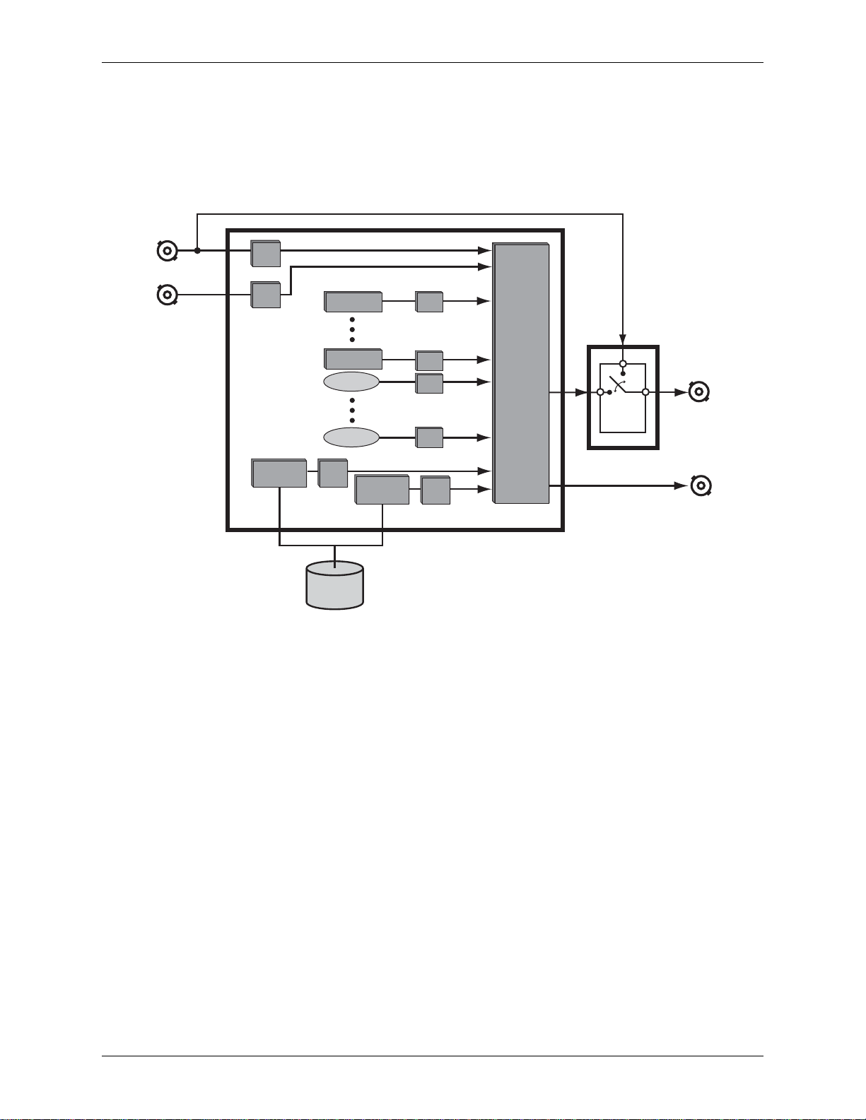
The main hardware processing engine of the DekoCast is the TARGA3200 board. All I/O, clip
processing, effects output, and keying is processed on the TARGA 3200 board. An illustration
that is representative of the signal flow for the DekoCast system is shown in Figure 2-1.
Video
Input
DVE
Deko CG
CAP
CAP
DVE
Internal
Objexs Processing
Clip
CODEC
DVEDeko CG
DVE
DVE
DVE
DVE
Keyer
Bypass
Relay
Daria Board
Video
Output
Key
Output
ideo/Key
Input
DVE
TARGA
3200
Board
Clip
CODEC
Clip Storage
Figure 2-1: DekoCast Signal Flow
Note: For DekoCast systems, the Clip option may or may not be installed. (It depends on how the system was
ordered.)
DekoCast Technical Reference And Service Guide
11
Page 12
Chapter 2: DekoCast System Overview
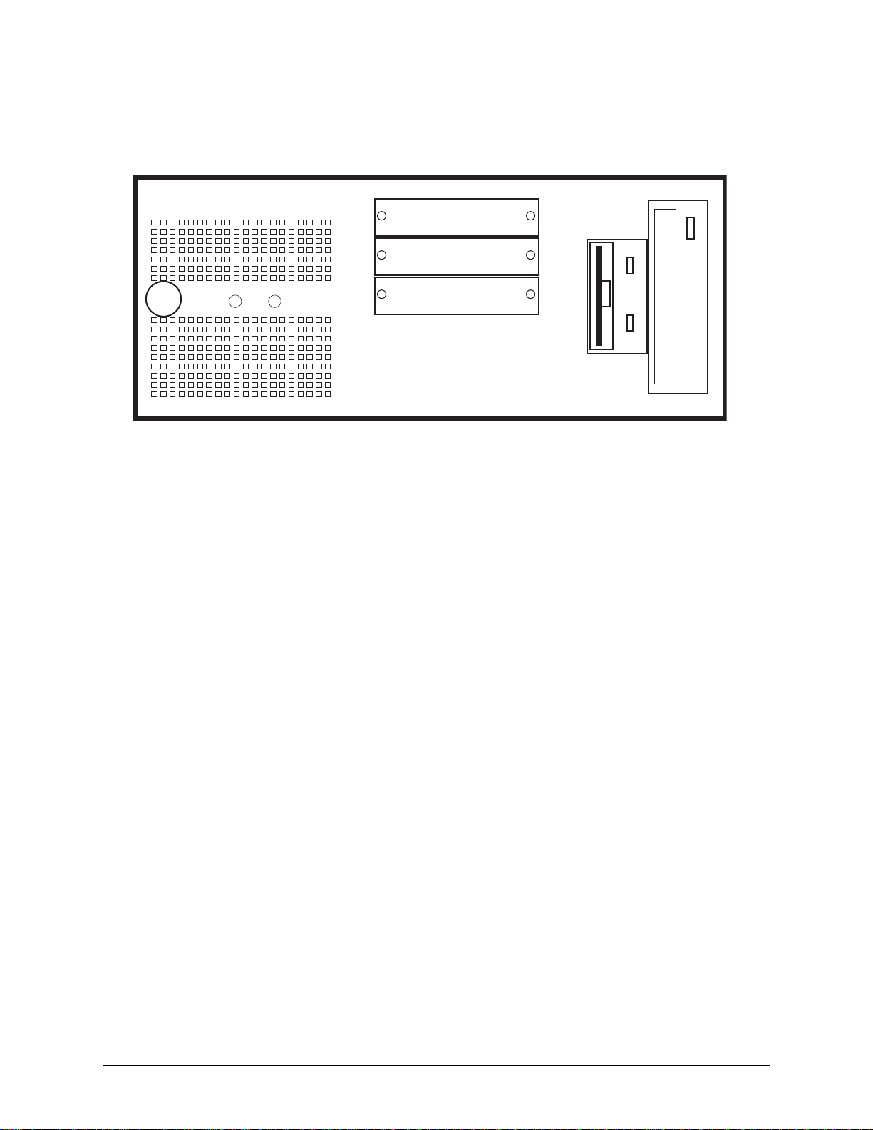
Workstation Front Panel
Figure 2-2 shows the front of the DekoCast workstation with the front cover removed.
DVD CD-ROM
SYSTEMSYSTEM
Floppy Drive
MEDIAMEDIA
USB
Power
On/Off
LED LED
Not Used
USB
Figure 2-2: Front Panel of DekoCast workstation (front panel cover removed)
The DekoCast workstations contain a floppy disk drive and a DVD/CD-ROM drive. The right
front panel has openings for inserting floppy disks and DVDs or CDs. To power on the machine,
first turn on the Power Supply switches on the back of a unit, then press the Power On/Off button
on the left side of the front panel. To power off the machine, first close all applications and shut
down the Windows operating system. Then turn of f the Power Supply switches on the back of the
machine. When a machine is powered On, the power light stays lit. A green light flashes
whenever the hard drive accesses data.
12
DekoCast Technical Reference And Service Guide
Page 13
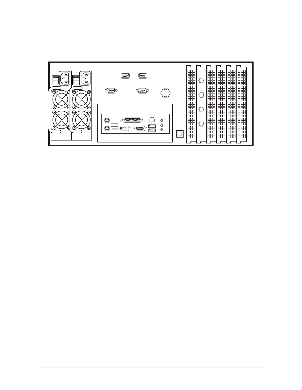
Workst ation Back Panel
Figure 2-3 shows the back of the DekoCast workstation.
Chapter 2: DekoCast System Overview
REDUNDANT POWER SUPPLIES
MOUSE
KEYBRD
SVGA
USB
RS422A RS422A
MANUAL
BYPASS
PARALLEL
SERIAL
UNUSED
NETWORK
USB
REFERENCE
ALARM
SILENCE
VIDEO
IN
VIDEO
OUT
KEY
IN
KEY
OUT
Figure 2-3: Back Panel of DekoCast workstation
The DekoCast workstation back panel (Figure 2-3) has two power supplies on the left, and AGP
and PCI card ventilation covers on the right. BNC connector plates for each TARGA 3200 board
in the workstation also double as ventilation covers. The cables from the TARGA 3200 cards are
fastened to the inside BNCs of the connector plates, which is labeled on the corresponding BNCs
on the outside the connection plates for each connection.
Each DekoCast workstation includes a pair of redundant hot-swappable Power Supplies. In the
event that one of the Power Supplies fails, the other will automatically take over to assure
continued operation of the workstation. A replacement Power Supply can be installed without
disrupting operation.
Important: Pinnacle Systems highly recommends that you purchase at least one spare Power Supply to
use in the event of a Power Supply failure. Contact Pinnacle Systems Customer Support (refer to
Appendix A) for ordering information.
Turn on the Power Supply switches before pressing the Power On/Off switch on the front panel.
When the power supplies are running, the Power LED on each power supply is green. When a
power supply is turned off or is not operational, the LED for that power supply is not lit. If a
power supply is not operational and the Power On/Off switch on the front panel is turned On, an
alarm will sound for the workstation. The workstation alarm can be turned off by pressing the
Alarm Silence button. Instructions for replacing a power supply can be found in Chapter 5:
System Maintenance.
The upper-middle part of the back panel contains the SVGA interface and the Genlock Reference
Input, which is internally connected to the TARGA 3200 board(s).
The recessed lower-middle panel has connectors for a keyboard and mouse, four available USB
ports, one parallel port, one serial port, and one LAN connector.
Important: A dongle which is necessary for the DekoCast software program to run is installed on the
parallel port. Do not remove the dongle.
DekoCast Technical Reference And Service Guide
13
Page 14

Chapter 2: DekoCast System Overview
14
DekoCast Technical Reference And Service Guide
Page 15

Chapter 3: Installation And Setup
Contents
This Chapter describes how to set up a DekoCast workstation after it has been initially received.
Information on installing the hard drives, attaching peripheral devices, testing the workstation,
DekoCast hardware settings software setup, and GPI control and network connections.
This Chapter contains the following sections:
• Unpacking
• DekoCast Workstation Initial Setup
• DekoCast Hardware Settings Window
• DekoCast GPI Input Connections
• DekoCast RS-422 Automation Control
• Daria Board Signal Flow
• Network Configuration
DekoCast Technical Reference And Service Guide
15
Page 16

Chapter 3: Installation And Setup
Unpacking
Please check to make sure that the following items have been included in the DekoCast packages
that were shipped:
-- Software CDs and DVDs
• DekoCast Software Application CD
• DekoCast Restore Image DVD
• Deko Fonts CD
• Instant CD/DVD Software CD
• Windows 2000 CD
These CD's are critical for the proper support of a DekoCast system. Please put them in a safe
location to insure timely support in the event that system maintenance is necessary. Misplacing
any of these CD's may result in a delay in servicing your DekoCast system.
-- Documents
• DekoCast Release Notes
• DekoCast Quick Install Guide
• Product Registration Card
Please read the Release Notes for important information about your new DekoCast System.
Also, take the time to fill out the Product Registration Card and return it to Pinnacle Systems.
Your filling out and sending the registration card enables Pinnacle Systems to inform you of any
important updates for your DekoCast system.
-- Hardware Components
• Main DekoCast Chassis
• System Drive (packed in separate box)
• Media Drive (packed in separate box)
• DekoCast Front Panel Cover
• Standard Mouse
• Standard Keyboard
• Two AC Power Cords (USA)
• Two AC Power Cords (International)
Note: Only two of the supplied power cords will be necessary for the DekoCast workstation. The type used is
dependent on the type of power outlet used in the facility where the DekoCast workstation will be located.
16
DekoCast Technical Reference And Service Guide
Page 17
Chapter 3: Installation And Setup
DekoCast Workstation Initial Setup
Before installing the DekoCast in your rack, the system should be put together, powered up, and
tested via a diagnostic test that comes pre-installed on the system. The steps for initially setting up
the workstation, powering it up, and testing it are as follows:
1. Visually inspect the hardwar e c omponents listed in the “Unpacking” section on the previous page to make sure that none of them were damaged during shipment
If you received a hardware component that was damaged, contact Pinnacle Systems
Customer Support. Contact information can be found in Appendix A of this document.
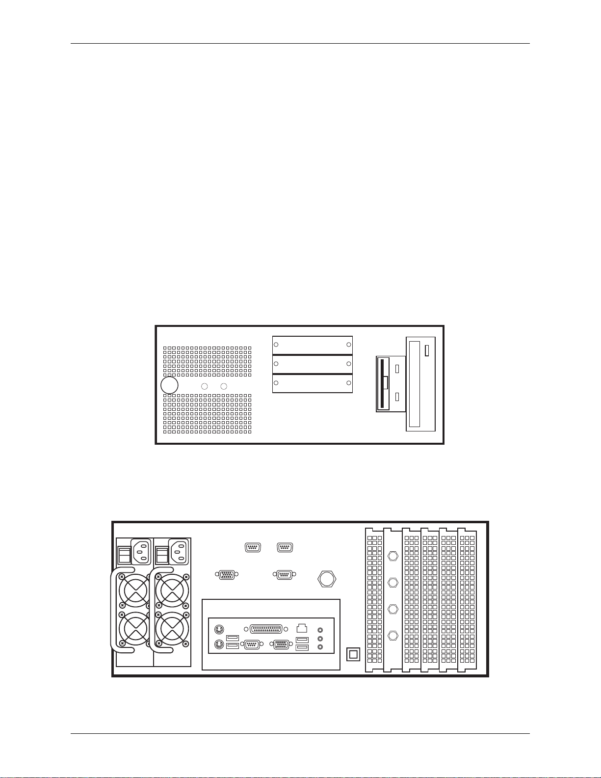
2. Insert the System hard drive and Media hard drive into their respective drive bays on
the front panel of the DekoCast workstation. Refer to Figure 3-1.
When placing a hard drive into its respective bay, align the drive so that it will properly slide
into the drive bay. Then push the drive so that it completely slides into the bay. This will
connect the drive to its connectors at the back of the bay. Use a screwdriver to completely
tighten the two thumbscrews. To insure that the connection stays intact, tighten the
thumbscrews as much as possible with the screwdriver.
DVD CD-ROM
Power
On/Off
LED LED
SYSTEMSYSTEM
MEDIAMEDIA
Not Used
Floppy Drive
USB
USB
Figure 3-1: Front Panel of DekoCast Workstation (front panel cover removed)
3. Attach the mouse and keyboard to the back panel of the workstation.
The mouse and keyboard connections on the workstation are shown in Figure 3-2.
REDUNDANT POWER SUPPLIES
SVGA
RS422A RS422A
MANUAL
BYPASS
REFERENCE
VIDEO
IN
VIDEO
OUT
MOUSE
USB
KEYBRD
Figure 3-2: Back Panel of the DekoCast Workstation
DekoCast Technical Reference And Service Guide
SERIAL
PARALLEL
UNUSED
NETWORK
USB
ALARM
SILENCE
KEY
KEY
OUT
IN
17
Page 18

Chapter 3: Installation And Setup
4. Attach the front panel cover (supplied) to the front of the DekoCast workstation.
The panel cover is the large plastic front panel cover that has the word DekoCast in red
lettering.
5. Connect a monitor (not supplied) to the DekoCast workstation.
The monitor attaches to the SVGA connector on the back of the DekoCast Workstation.
Refer to Figure 3-2.
6. Connect both AC Power Cords (supplied) the DekoCast workstation.
The AC power cords connect to both Power Supplies located at the back of the workstation.
Refer to Figure 3-2. Use the power cords appropriate for the electrical voltage range used by
the electrical outlet.
7. Turn on the monitor, and then power up the DekoCast workstation.
The workstation is power up by first pushing the Power Supply switches where the AC
Power Cords are connected to “On.” Then push the On/Off button located on the front panel
of the workstation to power up the workstation. When the operating system boots up, the
DekoCast background is displayed on the monitor.
8. Run the automatic mode of the I/O Diagnostic Utility to insure that the TARGA card is
functioning within the workstation.
For the TARGA card to be tested, the SDI channels for that card must be set to loop back.
This is done by taking two BNC cables (75 ohm) and connecting the Input/Output of each
channel as shown in Figure 3-3. The TARGA card BNC connectors are located on the back
panel of the workstation. The cable connection on the card for the test should be: Video Out
to Video In, and Key Out to Key In. Refer to Figure 3-3.
VIDEO IN
VIDEO OUT
KEY IN
KEY OUT
Figure 3-3: Loop Back Connections on each SDI Channel
Running the I/O Diagnostic Utility on a T ARGA card in a DekoCast workstation is a two step
process. First the “Fail Safe Test” software application program for the Daria Bypass Card
must be started. Once the “Fail Safe Test” application is running, the I/O Diagnostic Utility
program can be started and performed.
18
DekoCast Technical Reference And Service Guide
Page 19

Chapter 3: Installation And Setup
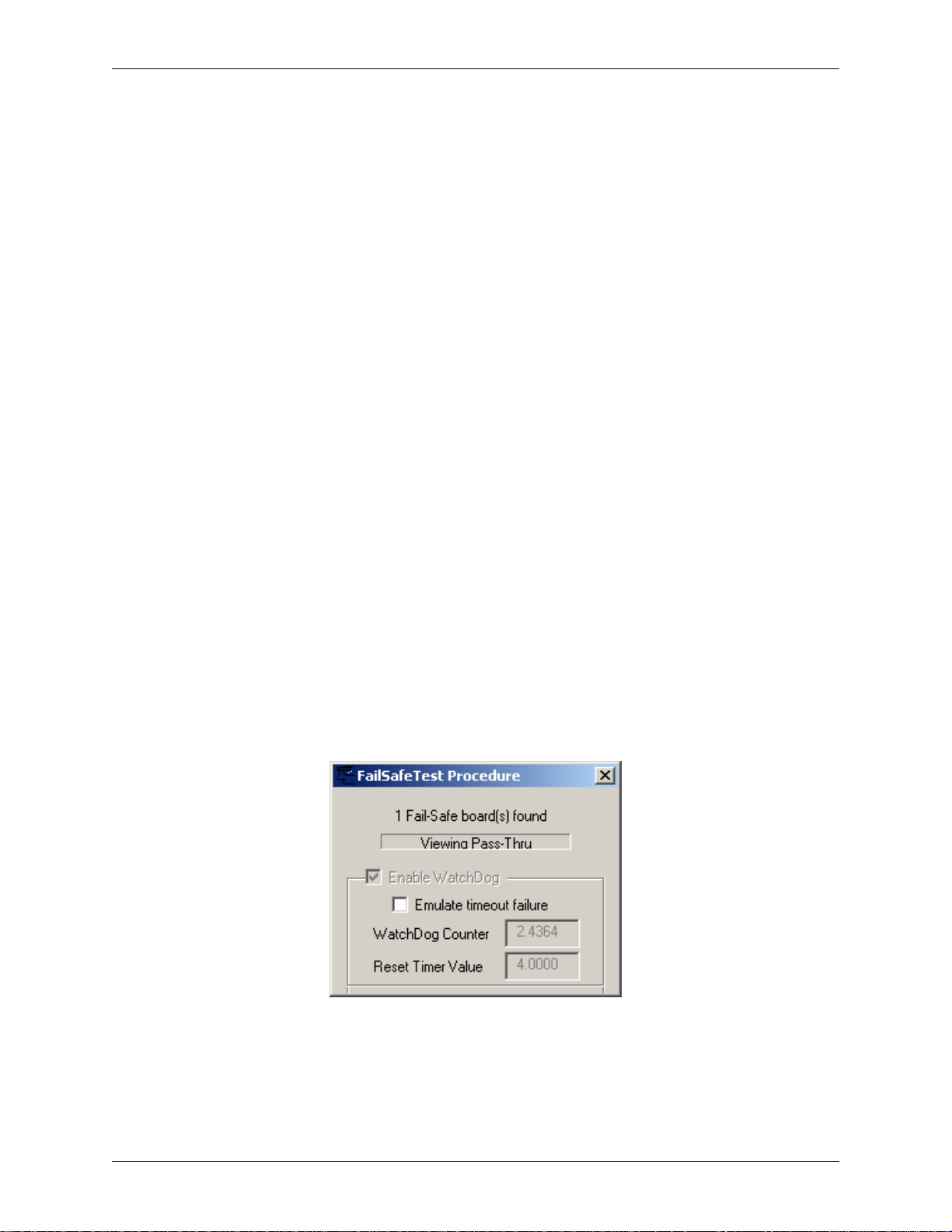
To start the “Fail Safe Test” application, navigate the following path within Windows:
Start menu >> Programs >>Pinnacle Systems >> Daria Passthrough
Then click the program “DariaPassthrough Test Procedure” to open it. Refer to Figure 3-4.
Figure 3-4: Daria Fail Safe Test
Important: Make sure that the “Emulate timeout failure” box is unchecked.
To start the I/O Diagnostic Utility application, navigate the following path to the Diagnostic
software program within Windows:
C:\ >> Program Files >> Pinnacle Systems >> TARGA Tester
Then click the program “I-O Diagnostic” to open it. Refer to Figure 3-5.
Figure 3-5: I/O Diagnostic Utility
Use the pull-down selection box on the upper left-hand side of the I/O Diagnostic window to
select “Board 1.” If you are facing the back panel of the workstation and looking at the
BNCs, then TARGA Board 1 would be the row of BNC’s on the far left. Then click the
“Start Full Test” button on the I/O Diagnostic window to run the automatic mode of the test.
If nothing fails on the test, the channel tested is fine.
A more detailed explanation of the I/O Diagnostic Utility program can be found in “Chapter
4: Troubleshooting” of this manual.
DekoCast Technical Reference And Service Guide
19
Page 20

Chapter 3: Installation And Setup
9. If the workstation is to be rack mounted or moved to another location, disconnect all of
the components and rack mount the workstation chassis.
Each DekoCast workstation chassis is designed so that industry standard rails can be
connected for rack mounting purposes. Each workstation will fit on 19-inch standard
instrument racks.
10. Make any other connections to the workstation that are necessary for the working
environment.
Other connections would include Genlock Reference, Video Input/Output BNCs, RS-422
automation, network cable, etc.
Note: The Audio connections (Speakers, Mic) on the back of the DekoCast chassis (refer to Figure 3-2) are
disabled at the factory and should not be used.
Repacking A DekoCast Workstation
When repacking your DekoCast system for shipment, please be sure to first remove the System
and Media drives and properly pack them with the system. This will protect the drives from
damage during shipment.
20
DekoCast Technical Reference And Service Guide
Page 21
Chapter 3: Installation And Setup
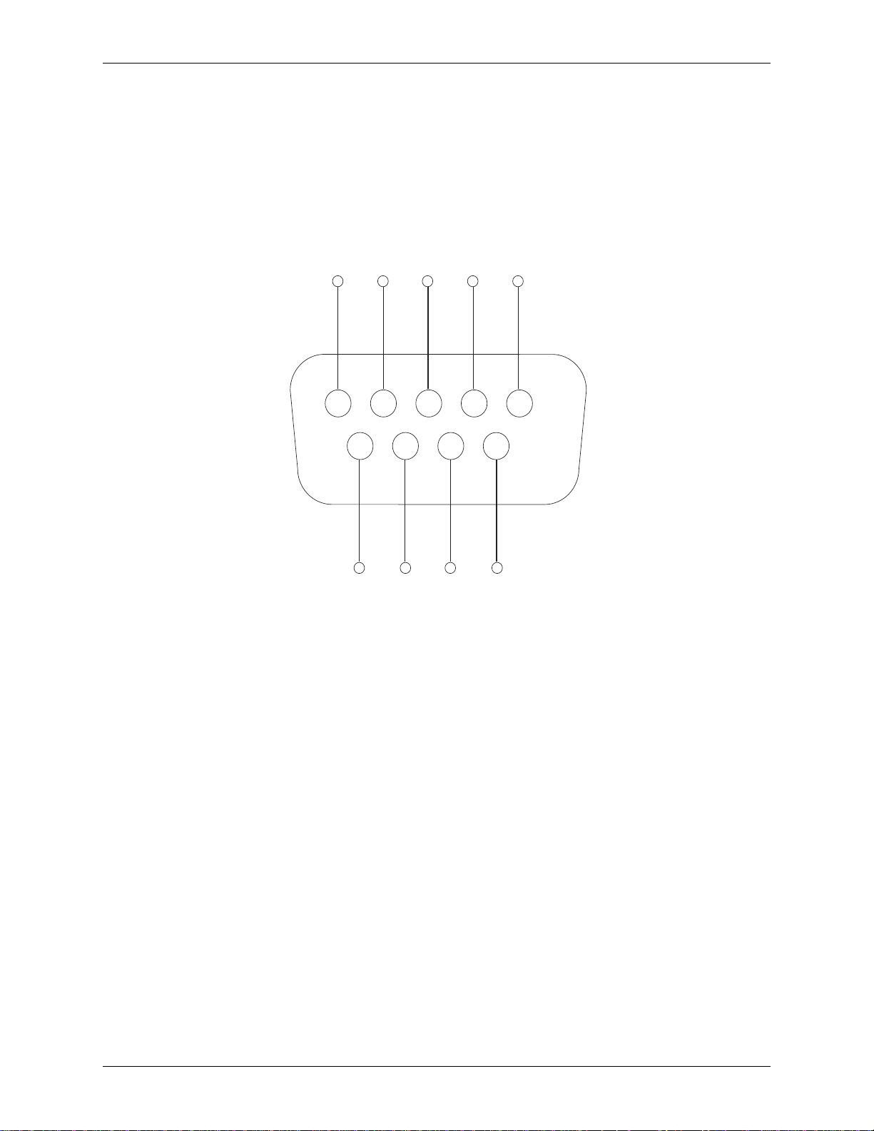
DekoCast GPI Input Connections
GPI’ s (General Purpos e Interface) can be us ed to interf ace DekoCa st with peripheral devices that
are capable of sending and receiving GPI pulses. A GPI Input can be selected from the Deko
Sequencer to trigger through a graphics sequence manually . For details on how to use GPIs within
the Deko application, refer to the “DekoCastCentral Guide” provided with your system.
The RS-232 port on the back of your DekoCast system can be repurposed to provide a pair of GPI
inputs. The diagram in Figure 3-7 below shows the pin connections on the RS-232 port that are
used as GPI’s.
12345
6789
Pin 6
Figure 3-6: DekoCast RS-232 Port Pinout
GPI_2
Pin 7
GPI_1
Pin 8
Pins 7 and 8 of the RS-232 connector are mapped to GPI-1 and Pins 6 and 7 are mapped to GPI-2
and can be used to detect a GPI from a standard contact closure (such as a GPI output from a
switcher). These GPI inputs can be selected from the DekoCast Central application to trigger
various events within the DekoCast system. Refer to the User documentation that can be found on
your DekoCast Software Application CD.
If you need more than 2 GPI inputs for your DekoCast, two external boxes are available from
Burst Electronics to provide up to 10 GPI inputs. The specific model numbers and ordering
information is listed as follows:
Model Number Description Ordering Information
GPI-10 RS-232 to GPI Converter, 10 GPI Inputs Must Specify “Pinnacle Firmware” when ordering
GPI-10K RS-232 to GPI Converter, 10 GPI Inputs Must Specify “Pinnacle Firmware” when ordering
(Includes built in Keypad)
For more information, refer to the Burst Electronics website at: www.burstelectronics.com
DekoCast Technical Reference And Service Guide
21
Page 22
Chapter 3: Installation And Setup
d)
R
d)
T
)
G
DekoCast RS-422 Automation Control
Your DekoCast system comes equipped with two industry standard RS-422 ports that can be used
for connecting to an automation system or for other control applications. These ports are labeled
as RS-422A and RS-422B on the back of the DekoCast chassis. Refer to Figure 3-2.
The pinouts for the RS-422 ports for automation control are shown in Figure 3-8.
Chassis
GND RX-
TX+
NC NC
12345
6789
GND
X- Receive (Negative End) NC (No Connect_Not Use
X+ Transmit (Positive End) RX+ Receive (Positive End
ND Ground
RX+ NC
TX-
TX- Transmit (Negative En
Figure 3-7: RS-422 Port Pinouts for Automation Control
These RS-422 ports will appear as standard COM3 (RS-422A) and COM4 (RS-422B) ports that
can be selected from the DekoCast Central Application or from a custom application that is
written for your DekoCast. Please refer to the DekoCast User documentation provided on the
application CD for more information.
22
DekoCast Technical Reference And Service Guide
Page 23
Chapter 3: Installation And Setup
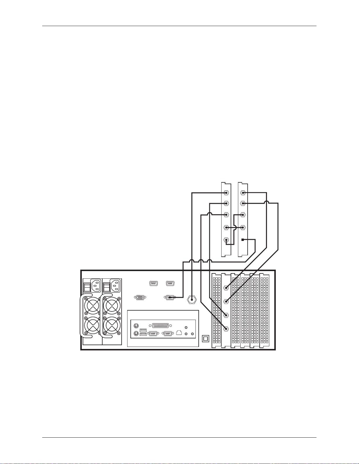
Daria Board Signal Flow
The Daria Bypass Card provides a passive bypass relay to the video signal being provided to and
from the TARGA card. That is, the Daria card operates in pass through mode where it passes an
incoming video signal to the TARGA card, and receives an outgoing video from the TARGA
card. The Daria Bypass Card will provide a continuous video signal for the following three
conditions:
1. Loss of power
2. Software lock-up
3. Over-Ride activation (available only if an over-ride switch is installed)
Important: The key output is not affected by the Daria Bypass Card, and therefore not protected from
the above three conditions.
A diagram showing how the TARGA and Daria Bypass Card are connected and thus the signal
flow for video signal protection to occur is shown in Figure 3-9.
TARGA
Inside Of Workstation Chassis
REF
DARIA
IN A
IN B
OUT A
REDUNDANT POWER SUPPLIES
SVGA
MOUSE
KEYBRD
RS422A RS422A
USB
SERIAL
PARALLEL
MANUAL
BYPASS
SERIAL
NETWORK
REFERENCE
SPEAKERS
OUT B
OUT A
VIDEO
VIDEO
ALARM
SILENCE
MIC
IN A
OUT
KEY
KEY
OUT
IN B
OUT B
OVER
RIDE
IN
IN
Figure 3-8: Signal Flow Connections Between TARGA and Daria Bypass Card within DekoCast Workstation
V ideo In and Video Out on a DekoCast system is always active. With that in mind, refer to Figure
3-9 above. The Video connections on the back of the DekoCast workstation are connected
directly to the Daria card. Thus, a video input signal coming into the “VIDEO IN” on the back of
the DekoCast workstation is routed to Daria “IN A.” The signal is then passed within the Daria
Bypass Card to Daria “OUT B” which in turn routes the signal into the TARGA card at TARGA
“IN A.”
DekoCast Technical Reference And Service Guide
23
Page 24

Chapter 3: Installation And Setup
A video output signal from the TARGA card comes out of TARGA “OUT A” and goes into the
Daria Bypass Card at Daria “IN B.” The signal is then passed within the Daria Bypass Card to
Daria “Out A” and sent to “Video Out” on the back of the workstation
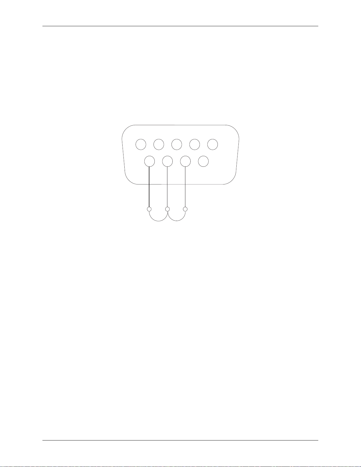
Over-Ride Switch Pinouts
Pins 1 and 2 on a DB9 connector are used to force the Daria bypass board into fail-over mode
(video input hardwired to the output). Refer to Figure 3-10. A simple contact closure will trigger
the bypass mode.
12345
6789
Figure 3-9: Pinouts on a DB9 Connector
Network Configuration
Contact the IT System Administrator at the facility where the DekoCast workstation is to be
installed to obtain detailed information about how to configure your system for the Network.
The following guidelines are outlined for the IT department to use to protect your DekoCast
system from virus infection. While it is understood that all of these guidelines may not be
practical, following them will provide the best level of protection against system infection.
1. NEVER share a folder or drive to “Everyone” with full-access.
2. ALWAYS assign a local Administrator password on every machine. Not assigning a local
Administrator password can introduce a serious security risk.
3. Do not store files with a .exe extension in directories with write permissions.
4. If possible, keep all Pinnacle Live Production equipment on a separate network that is isolated from other machines in the facility.
5. Disallow Internet access on any Pinnacle Live Production machines that do not require it.
6. Do not install anti-virus software on any of the Pinnacle supplied hardware components that
are used on-air.
7. Install and run anti-virus software on all PC components that are not used for on-air play out.
This includes Pinnacle products such as DekoCast Authoring Station, PostDeko, DekoMOS
Clients, Lightning Browse, and Thunder Browse.
24
Note: Please refer to the “Virus Protection Recommendations for Pinnacle Systems Live Production
Products” white paper for additional guidelines on how to protect your Deko system from virus infection.
This and other White Paper and Application Notes can be found on Pinnacle’s website at
www.pinnaclesys.com
DekoCast Technical Reference And Service Guide
Page 25

Chapter 4: Troubleshooting
Contents
This Chapter describes how to use software utilities provided with each DekoCast Workstation
system software as a means to quickly and easily troubleshoot the workstation. Troubleshooting
tips are also provided. Performing these procedures will help streamline the process of getting
your DekoCast Workstation up and running again.
This Chapter contains the following sections:
• I/O Diagnostic Utility
• Deko Manifest Utility
DekoCast Technical Reference And Service Guide
25
Page 26

Chapter 4: Troubleshooting
I/O Diagnostic Utility
The Input/Output (I/O) Diagnostic software test utility provides a range of tests if you, or Pinnacle
Systems Customer Support, suspect that there is a problem with the TARGA 3200 card in a
DekoCast Workstation. The procedures described for performing the I/O Diagnostic should be
perform before contacting Customer Support. If a TARGA card is the problem, downtime is kept
to a minimum since the problem is quickly identified.
Problems that may lead one to run the I/O Diagnostic Utility are as follows:
• No picture being output from the workstation
• Video looks bad or rolls continuously (no genlock)
• Effects of clips stutter
• Video capture and playback not working
• Audio is scrambled
Modes Of Operation
The I/O Diagnostic test can be used in two different modes: automatic or manual. The automatic
testing runs a list of tests until either an error is detected, or until all the tests are successfully
completed. In most instances, the automatic test mode is used. Manual testing allows you to
select a test individually from the list of tests and run it. You can run each test individually by
manual selection if directed to do so by Pinnacle Systems Customer Support.
Setup Before Testing
The setup procedures given below for automatic and manual test modes should be perform before
running the I/O Diagnostic test.
Setup for automatic test mode:
For a TARGA card to be tested, the SDI channels must be set for loop back. This is done by
taking two BNC cables (75 ohm) and connecting a TARGA card that is to be tested to itself. The
cable connection on the card should be: Video Out to Video In, and Key Out to Key In. Refer to
Figure 4-1.
VIDEO IN
VIDEO OUT
KEY IN
KEY OUT
26
Figure 4-1: Loop Back Connections on a TARGA Card
DekoCast Technical Reference And Service Guide
Page 27
Chapter 4: Troubleshooting
Setup for manual test mode:
If the NTSC Genlock or PAL Genlock test is to be done, then an input black burst signal must be
connected to the REF input connector on the back of the DekoCast chassis. An input NTSC
signal source must be used for the NTSC Genlock test. An input PAL signal source must be used
for the PAL Genlock test.
If manual testing of the SDI channels is to be done, the SDI channel to be tested must be set for
loop back. Refer to “Setup for automatic test mode” above and Figure 4-1. Channel 1 is Video
Out (Out A) to Video In (In A). Channel 2 is Key Out (Out B) to Key In (In B).
Automatic Test Procedure
The following steps should be performed for automatic testing of T ARGA card within a DekoCast
Workstation by way of the I/O Diagnostic Utility test:
1. Turn on the DekoCast Workstation.
Only the Windows OS should be running. If any other programs are running on the
workstation, then you should exit out of those programs.
Important: If your workstation is corrupted to the point where it will not boot up when turned on,
contact Pinnacle Systems Technical Support. Contact information can be found in Appendix A.
2. Start the Daria Fail Safe Test software program.
The “Fail Safe Test” software application program for the Daria Bypass Card must be
started before the I/O Diagnostic software test for the TARGA can be run. Once the “Fail
Safe Test” application is running, the I/O Diagnostic Utility program can be started and
performed.
To start the “Fail Safe Test” application, navigate the following path within Windows:
Start menu >> Programs >>Pinnacle Systems >> Daria Passthrough
Then click the program “DariaPassthrough Test Procedure” to open it. Refer to Figure 4-2.
Figure 4-2: Daria Fail Safe Test
Important: Make sure that the “Emulate timeout failure” box is unchecked.
DekoCast Technical Reference And Service Guide
27
Page 28
Chapter 4: Troubleshooting
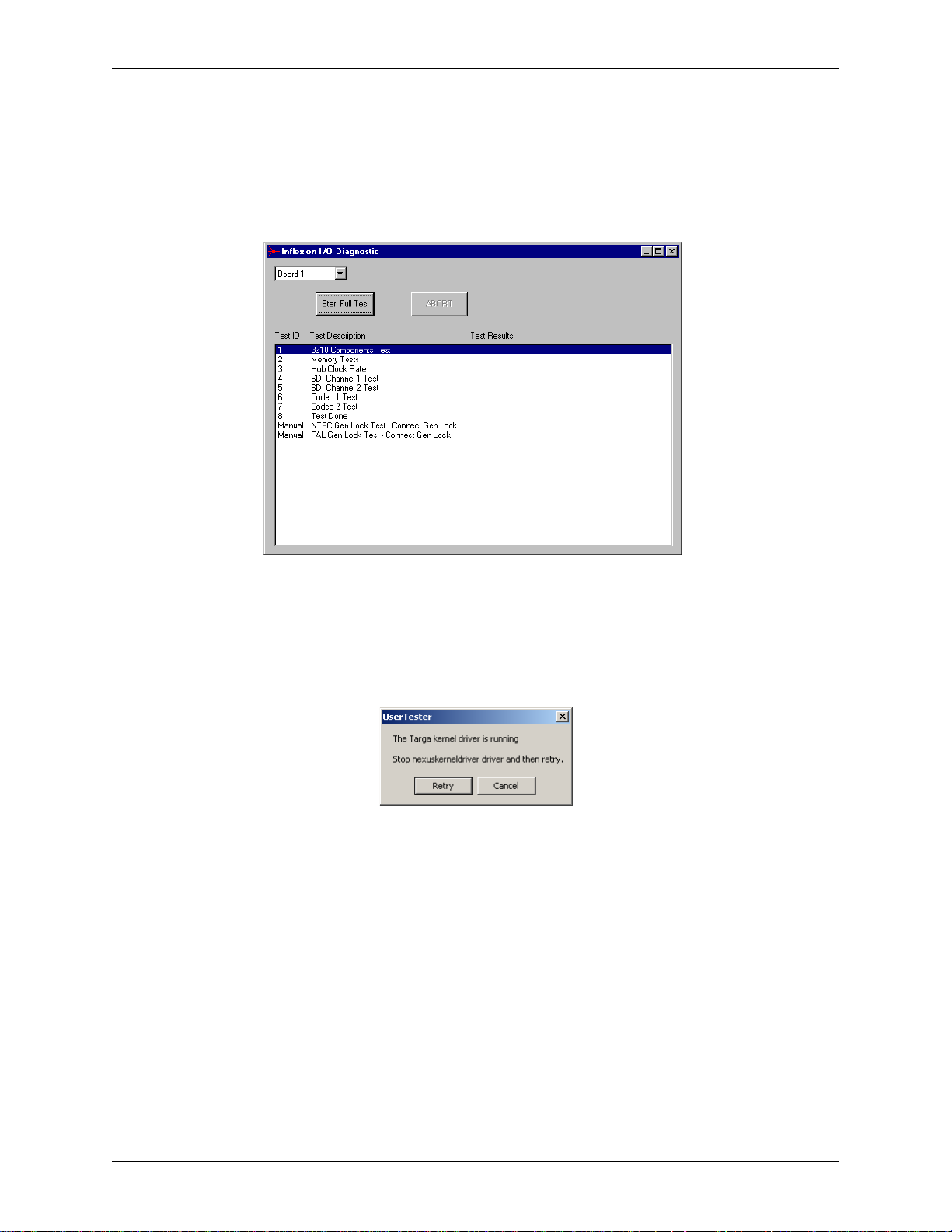
3. Start the I/O Diagnostic software program.
T o start the I/O Diagnos tic Utility application, navigate the following path to the Diagnostic
software program within Windows:
C:\ >> Program Files >> Pinnacle Systems >> TARGA Tester
Then click the program “I-O Diagnostic” to open it. Refer to Figure 4-3.
Figure 4-3: Initial start up screen of I/O Diagnostic Test
Note: Depending on the model of the TARGA card in your system, the “3210” indication may appear as a
different number.
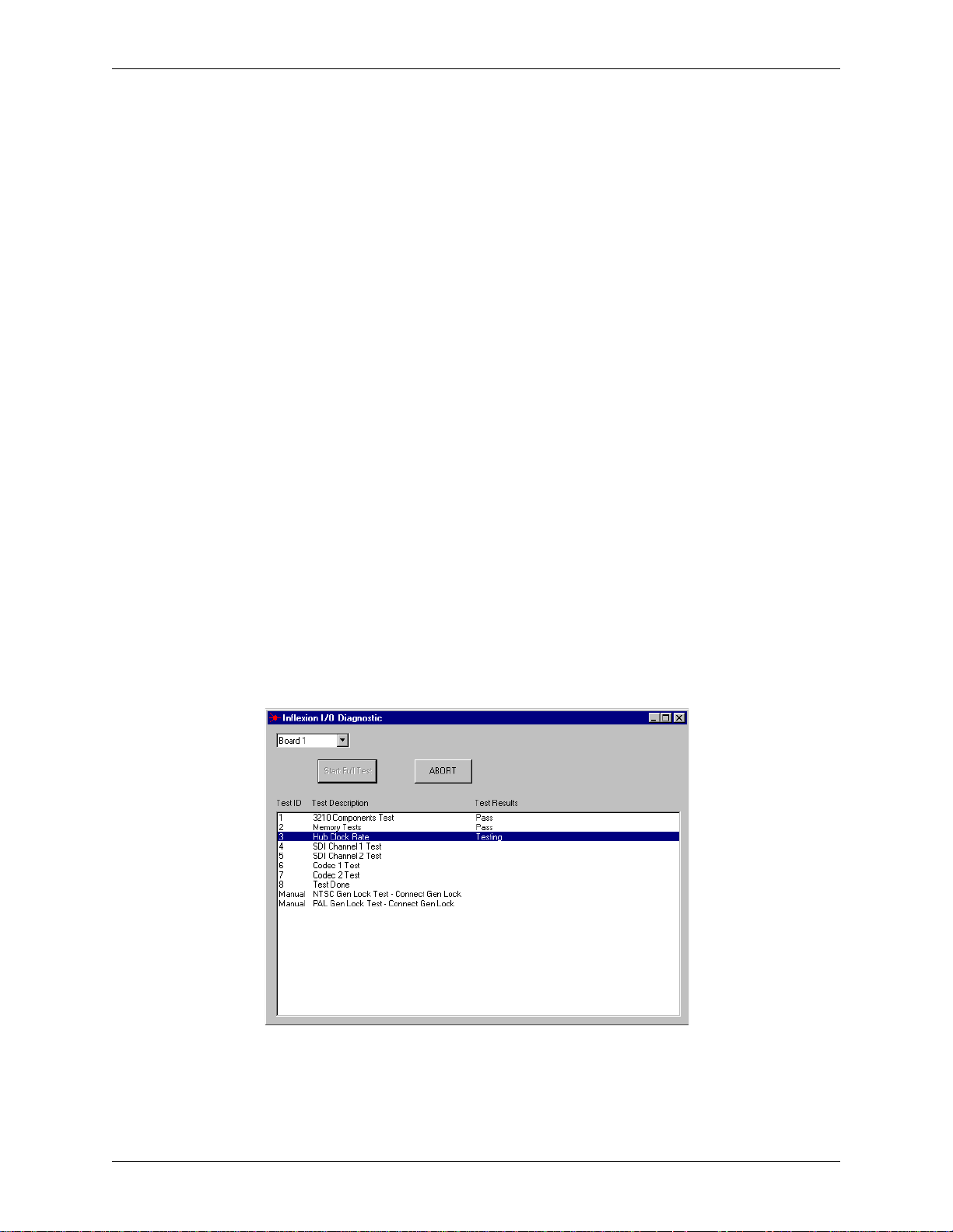
Important: If the dialog shown in Figure 4-4 is displayed, then either the Deko program is also
running, or some other program is running that interferes with the I/O Diagnostic.
Figure 4-4: TARGA kernel driver interference dialog
Quit all other programs and restart the workstation. Repeat Step 2 so that only the I/O Diagnostic
program is running.
4. Select the channel that is to be tested.
There is a pull-down selection box on the upper left-hand side of the I/O Diagnostic
window. The default selection in the pull down is Board 1 (i.e., first channel). Refer to
Figure 4-3. The selection and identification of a board is as follows:
• Board 1 -- This is the TARGA card, which is essentially the channel. If you are facing the back
panel of the workstation and looking into the TARGA card bay area, then Board 1 would be the
T ARGA card on the far left. If the workstation top is lifted off, the TARGA card would be seated
right next to the Serial 422 card. (Refer to Figure 5-1 within the “Replacing Workstation Components” section of Chapter 5 for the TARGA card location)
28
DekoCast Technical Reference And Service Guide
Page 29
Chapter 4: Troubleshooting
• Board 2 -- This pull down selection is not used with a DekoCast workstation because DekoCast
only uses one TARGA card.
• Board 3 -- This pull down selection is not used with a DekoCast workstation because DekoCast
only uses one TARGA card.
• Board 4 -- This pull down selection is not used with a DekoCast workstation because DekoCast
only uses one TARGA card.
Important: Loop back must be set up on the TARGA card channel before running the test. Refer to
the “Setup Before Testing” section above for automatic testing procedures.
5. Click the “Start Full Test” button on the I/O Diagnostic window.
Brief descriptions of the tests are as follows:
• 3210 Components Test -- This test checks that the various components on the TARGA card are
functioning in a normal manner.
Note: Depending on the model of the TARGA card in your system, the “3210” indication may appear as a
different number.
• Memory Tests -- This test performs extensive memory testing on the TARGA card.
• Hub Clock Rate -- This is a test to check that the TARGA’s “clock” locks to the oscillator.
• SDI Channel Tests -- This test loops a signal out of the SDI portion of a channel and checks that
the signal comes back into the card exactly the same.
• Codec Tests -- This test checks the encoding and decoding ability of a Codec by putting a fixed
image through the Codec.
When the “Start Full Test” button is clicked, the automatic testing sequence for the channel
(i.e., board) selected in the pull down will begin. The automatic test takes about 3 minutes
to complete. An example of automatic testing in progress is shown in Figure 4-5.
Figure 4-5: I/O Diagnostic automatic test in progress
DekoCast Technical Reference And Service Guide
29
Page 30
Chapter 4: Troubleshooting
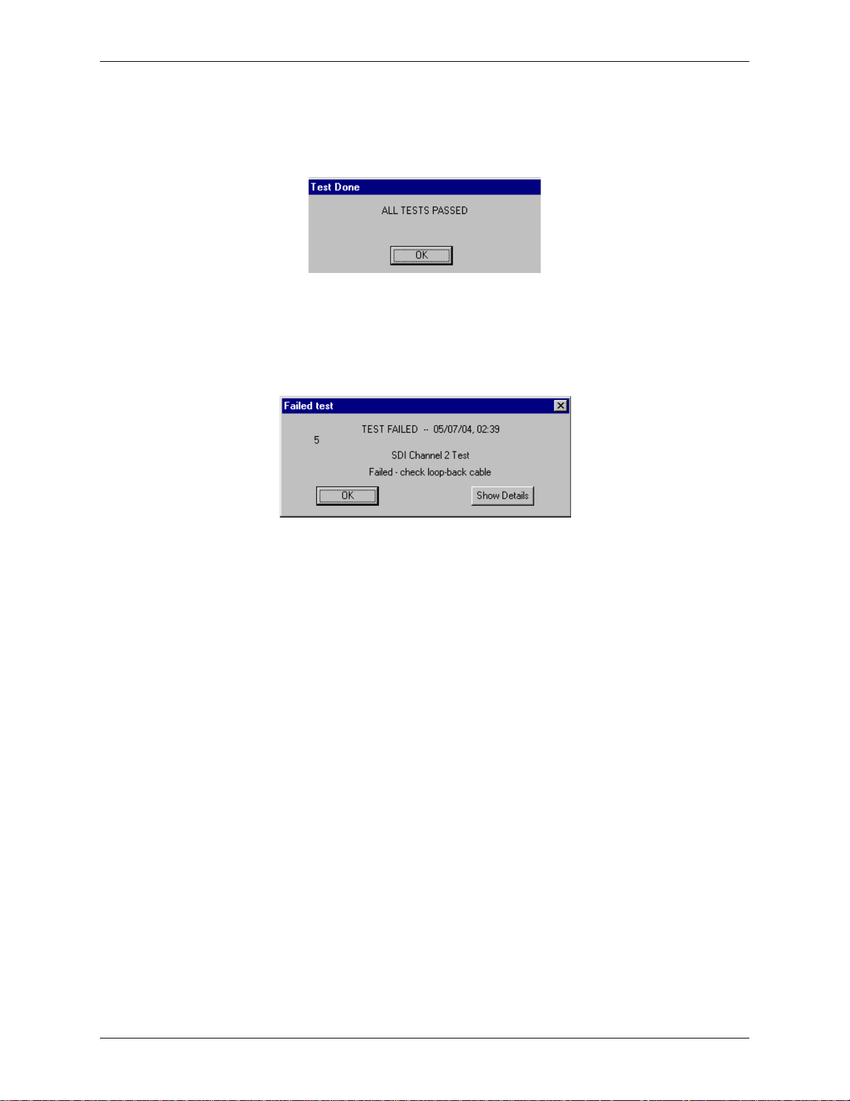
If all automatic tests pass:
If automatic testing completes successfully, a dialog stating that the tests are done and all test
passed will be displayed. Click the “OK” button within the dialog. Refer to Figure 4-6.
Figure 4-6: Dialog shown when all automatic tests pass
If an automatic test fails:
The automatic testing sequence will stop at the point that a test fails, and the dialog shown in
Figure 4-7 will be displayed.
Figure 4-7: Dialog shown when an automatic test fails
Details about a test that fails can be viewed by clicking the “Show Details” button on the Failed
Test dialog. If it was one of the SDI Channel tests that failed, check that the loop through cables
are connected properly to the TARGA card. (Refer to the “Setup Before Testing” section above
for automatic testing setup procedures.)
Perform the following steps if a test fails:
1. After viewing the details, click “OK” on the dialog and repeat the automatic test.
Make sure that the TARGA card is properly seated, and loop through cables are secure and
properly connected before repeating the automatic test sequence.
Important: Power down the workstation before removing the cover to make sure that the TARGA
card is properly seated in its PCI slot.
2. If the test fails again, click “OK” on the Failed Test dialog and save results.
Results can be saved by right clicking on the blue title bar or red icon (upper left-hand
corner) of the I/O Diagnostic window and selecting “Save Results.” Refer to Figure 4-8.
30
DekoCast Technical Reference And Service Guide
Page 31

Chapter 4: Troubleshooting
Figure 4-8: Selecting “Save Results” for I/O Diagnostic window
When saved results is selected, the window shown in Figure 4-9 will be displayed.
Figure 4-9: Save Results Window
3. Type a Filename in the Filename area and a brief description of the problem.
When typing a filename for the Save Results file, make sure to use an extension such as .txt
(an example would be: testfailed.txt as a filename). If you know thew TARGA card’ s serial
number, include when typing a brief description of the problem.
Important: When typing a brief description of the problem do no use the <Enter> key on your
keyboard. The <Enter> key will cause the Save Results window to unexpectedly close.
4. Click the “Save” button.
The Save Results file will be saved in the same folder where the I-O Diagnostic test is
located on the DekoCast Workstation. Pinnacle Systems Technical Support may request
that you send this file to them. An example of a saved T est Results file is shown in Figure 4-
10.
DekoCast Technical Reference And Service Guide
31
Page 32

Chapter 4: Troubleshooting
Figure 4-10: Example of a saved Test Results file
5. Contact Pinnacle Systems Technical Support.
Pinnacle Systems Technical Support will provide you instructions on the procedure to
obtain a replacement TARGA card. Contact information can be found in “Appendix A:
Pinnacle Systems Technical Support.”
Manual Test Procedure
The following steps should be performed for manual testing of the TARGA card within a
DekoCast Workstation by way of the I/O Diagnostic Utility test:
1. Turn on the DekoCast Workstation.
Only the Windows OS should be running. If any other programs are running on the
workstation, then you should exit out of those programs.
Important: If your workstation is corrupted to the point where it will not boot up when turned on,
contact Pinnacle Systems Technical Support. Contact information can be found in Appendix A.
2. Start the Daria Fail Safe Test software program.
The “Fail Safe Test” software application program for the Daria Bypass Card must be
started before the I/O Diagnostic software test for the TARGA can be run. Once the “Fail
Safe Test” application is running, the I/O Diagnostic Utility program can be started and
performed.
To start the “Fail Safe Test” application, navigate the following path within Windows:
Start menu >> Programs >>Pinnacle Systems >> Daria Passthrough
Then click the program “DariaPassthrough Test Procedure” to open it. Refer to Figure 4-11.
32
Figure 4-11: Daria Fail Safe Test
Important: Make sure that the “Emulate timeout failure” box is unchecked.
DekoCast Technical Reference And Service Guide
Page 33

Chapter 4: Troubleshooting
3. Start the I/O Diagnostic software program.
Navigate the following path to the I/O Diagnostic software program:
Start >> Programs >> DekoCast >> Diagnostic Tools
Then click the program “I-O Diagnostic” to open it. A window similar to that shown in
Figure 4-12 should be displayed.
Figure 4-12: Initial start up screen of I/O Diagnostic Test
Note: Depending on the model of the TARGA card in your system, the “3210” indication may appear as a
different number.
Important: If the dialog shown in Figure 4-13 is displayed, then either the Deko program is also
running, or some other program is running that interferes with the I/O Diagnostic.
Figure 4-13: TARGA kernel driver interference dialog
Quit all other programs and restart the workstation. Repeat Step 2 so that only the I/O Diagnostic
program is running.
4. Select the channel that is to be tested.
There is a pull-down selection box on the upper left-hand side of the I/O Diagnostic
window. The default selection in the pull down is Board 1 (i.e., first channel). Refer to
Figure 4-12. The selection and identification of the TARGA is as follows:
• Board 1 -- This is the TARGA card, which is essentially the channel. If you are facing the back
panel of the workstation and looking into the TARGA card bay area, then Board 1 would be the
T ARGA card on the far left. If the workstation top is lifted off, the TARGA card would be seated
right next to the RS- 422 card. (Refer to Figure 5-1 within the “Replacing Workstation Components” section of Chapter 5 for the TARGA card location)
• Board 2 -- This pull down selection is not used with a DekoCast workstation because DekoCast
only uses one TARGA card
DekoCast Technical Reference And Service Guide
33
Page 34

Chapter 4: Troubleshooting
• Board 3 -- This pull down selection is not used with a DekoCast workstation because DekoCast
only uses one TARGA card.
• Board 4 -- This pull down selection is not used with a DekoCast workstation because DekoCast
only uses one TARGA card.
5. Double click the test name that is to be run.
A single test can be performed by left-double clicking the name of the test. An example of
the manual testing window is shown in Figure 4-14.
Figure 4-14: I/O Diagnostic manual testing window
Brief descriptions of the tests are as follows:
• 3210 Components Test -- This test checks that the various components on the TARGA card are
functioning in a normal manner.
Note: Depending on the model of the TARGA card in your system, the “3210” indication may appear as a
different number.
• Memory Tests -- This test performs extensive memory testing on the TARGA card.
• Hub Clock Rate -- This is a test to check that the TARGA’s “clock” locks to the oscillator.
• SDI Channel Tests -- This test loops a signal out of the SDI portion of a channel and checks that
the signal comes back into the card exactly the same.
Important: Loop back must be set up on the TARGA card before running the test. Refer to the
“Setup Before Testing” section above.
• Codec Tests -- This test checks the encoding and decoding ability of a Codec by putting a fixed
image through the Codec.
• Genlock T ests -- The NTSC and the PAL genlock tests both use a black burst or composite signal
as input source to Reference (REF) on the TARGA card. Either test locks the TARGA’s output
to the reference, and then tests to check if it is really locked to the reference output. The test then
checks that unlocking can occur. You must reboot after performing a Genlock test
Important: An input black burst or composite input signal must be connected to the REF 1
connector on the back panel of the workstation if a genlock test is to be done. The input signal
format (i.e., NTSC or PAL) must match the format listed in the test name description.
.
34
DekoCast Technical Reference And Service Guide
Page 35

Chapter 4: Troubleshooting
If manual tests pass:
When a manual test is done, a Pass/Fail message will be displayed in a column to the right of the
test name. Refer to Figure 4-14.
If a manual tests fails:
When a manual test is done, a Pass/Fail message will be displayed in a column to the right of the
test name. Details about a test that fails can be viewed by clicking on the test name with a single
left mouse click which will highlight the test name and test result. Once highlighted, right double
click on the highlighted name for a dialog detailing the failure. If it was one of the SDI Channel
tests that failed, check that the loop through cables are connected properly to the TARGA card
being tested. If a genlock tests failed, check the signal input on the Reference. (Refer to the
“Setup Before Testing” section above for manual testing setup procedures.)
Perform the following steps if a test fails
1. Repeat the manual test.
Make sure that the TARGA card is properly seated, and loop through cables are secure and
properly connected before repeating the manual test.
Important: Power down the workstation before removing the cover to make sure that the TARGA
card is properly seated in its PCI slot.
2. If the test fails again, save the results.
Results can be saved by right clicking on the blue title bar or red icon (upper left-hand
corner) of the I/O Diagnostic window and selecting “Save Results.” Refer to Figure 4-15.
Figure 4-15: Selecting “Save Results” for a manual test failure
When saved results is selected, the window shown in Figure 4-16 will be displayed.
DekoCast Technical Reference And Service Guide
35
Page 36

Chapter 4: Troubleshooting
Figure 4-16: Save Results Window
3. Type a Filename in the Filename area and a brief description of the problem.
When typing a filename for the Save Results file, make sure to use an extension such as .txt
(an example would be: testfailed.txt as a filename). If you know thew TARGA card’ s serial
number, include when typing a brief description of the problem.
Important: When typing a brief description of the problem do no use the <Enter> key on your
keyboard. The <Enter> key will cause the Save Results window to unexpectedly close.
4. Click the “Save” button.
The Save Results file will be saved in the same folder where the I-O Diagnostic test is
located on the DekoCast Workstation. Pinnacle Systems Technical Support may request
that you send this file to them. An example of a saved T est Results file is shown in Figure 4-
17.
Figure 4-17: Example of a saved Test Results file
5. Contact Pinnacle Systems Technical Support.
Pinnacle Systems Technical Support will provide you instructions on the procedure to
obtain a replacement TARGA card. Contact information can be found in “Appendix A:
Pinnacle Systems Technical Support.”
36
DekoCast Technical Reference And Service Guide
Page 37
Chapter 4: Troubleshooting
Deko Manifest Utility
The Deko Manifest test provides a view of the of software components within the DekoCast
workstation. This test compares the registered software components with the official record of a
software release and looks for mismatches. This is useful in identifying workstation software
components that may have become corrupt, or software that may be incompatible with DekoCast
software. This test is also useful in identifying configuration problems that may have occurred in
a DekoCast workstation.
Important: This is a test that should only be used with Pinnacle Systems Customer Support supervision.
Customer Support personnel will be able to properly analyze the results of this test, and then determine the
steps necessary to solve the problem being experienced with the workstation.
Deko Manifest Test Procedure
The following steps should be followed to performed the Deko Manifest Utility test:
1. Turn on the DekoCast Workstation.
Only the Windows OS should be running. If any other programs are running on the
workstation, then you should exit out of those programs.
Important: If your workstation is corrupted to the point where it will not boot up when turned on,
contact Pinnacle Systems Technical Support. Contact information can be found in Appendix A.
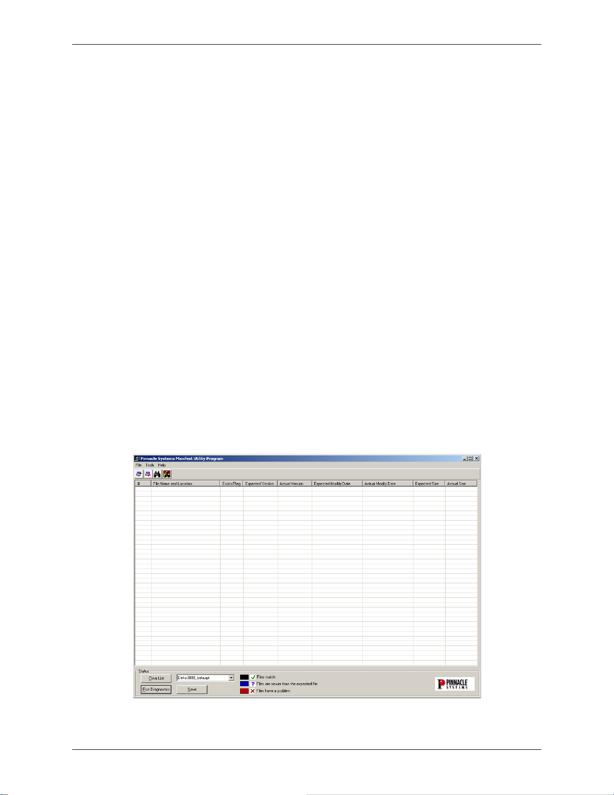
2. Start the Deko Manifest Utility software program.
Navigate the following path to the Deko Manifest software program:
Start >> Programs >> DekoCast >> Diagnostic Tools
Then click the program “DekoManifestUtility” to open it. A Window similar to that shown in
Figure 4-18 should be displayed.
Figure 4-18: Initial start-up screen of Manifest Utility Test
DekoCast Technical Reference And Service Guide
37
Page 38

Chapter 4: Troubleshooting
3. Select the set of software components that are to be tested.
From the pull down on the bottom part of the Manifest Utility start-up screen, select the set
of software components that are to be selected. Refer to Figure 4-19. The choices are
“DekoCast” and “Manifest.”
• DekoCast -- This choice will compare the DekoCast software programs on the workstation being
tested to the official record of the Pinnacle Systems release for the DekoCast software.
• Manifest -- This choice will compare the software programs on the workstation being tested to
the official record of the Pinnacle Systems release for the software.
Figure 4-19: Software components selection for Manifest Utility test
4. Click the “Run Diagnostics” button on the Manifest Utility program window.
Clicking the “Run Diagnostics program will cause the comparison test for the selected
workstation components to be made. For the DekoCast components, a window similar to
that shown in Figure 4-20 will be displayed.
Figure 4-20: Example results from Manifest Utility program
A window similar to that shown in Figure 4-20 will be displayed if the test is run for the
software components.
38
DekoCast Technical Reference And Service Guide
Page 39

Chapter 4: Troubleshooting
5. Save the results of the test.
Pinnacle Systems Customer Support will either ask to be sent a copy of the file, or go over
the results of the test with you over the phone. Therefore save the results of the test by
clicking the “Save” button on the Manifest Utility program window to capture the window
and save the results. When the “Save” button is clicked, a “Save File As...” window similar
to that shown in Figure 4-21 will be displayed.
Figure 4-21: Example File Save As Window
From the “Save in” pull down at the top upper left of the File Save As window, select the
location that the result of the Deko Manifest test will be saved. Refer to Figure 4-22.
Figure 4-22: Selecting saved location for test results
The file will be saved as an Internet Explorer.html file in the location that you indicated.
DekoCast Technical Reference And Service Guide
39
Page 40

Chapter 4: Troubleshooting
6. Click the “Clear List” button to test the other set of software components listed in the
Deko Manifest screen pull-down list.
Click on the “Clear List” button to refresh the Manifest Utility window so that it looks
similar to what is shown in Figure 4-23.
Figure 4-23: Manifest Utility window refreshed with “Clear List” button
7. Select the other set of software components listed in the Deko Manifest screen pulldown list.
From the pull down on the bottom part of the Manifest Utility start-up screen, select the
other set of software components (i.e., the one not previously tested). Refer to Figure 4-19.
Your choice will either be “DekoCast” or Manifest.
8. Perform Steps 4 and 5 listed above to complete testing.
Once the second set of file components file has been tested and saved, Deko Manifest
Utility testing is completed. Follow the instructions given to you by Pinnacle Systems
Customer Support in order to get the saved files to them.
Interpreting Deko Manifest Test Results
The Deko Manifest Utility test compares the registered software components on the workstation
being tested with the official record of a software release. Files that match are indicated with a
green check mark and normal black text. Files that are newer on the workstation than what the
official release record shows are indicated with a blue “?” and blue text. Files that have a problem
are indicated with a red “x” and red text. Refer to Figure 4-24.
40
DekoCast Technical Reference And Service Guide
Page 41

Chapter 4: Troubleshooting
Figure 4-24: Example Deko Manifest results with possible problems
Important: It does not necessarily mean that the DekoCast workstation being tested is malfunctioning
just because the results of a Deko Manifest test may have blue or red files indicated. In fact, some
workstations are suppose to have files indicated this way. This is why it is absolutely imperative that a
Pinnacle Systems Customer Support representative interprets the test results and recommends to you how
to proceed. This is also why the Internet Explorer .html file of the Deko Manifest results saved in the
procedures above must be sent to Customer Support. Contact information can be found in “Appendix A:
Pinnacle Systems Technical Support.”
DekoCast Technical Reference And Service Guide
41
Page 42

Chapter 4: Troubleshooting
42
DekoCast Technical Reference And Service Guide
Page 43

Chapter 5: System Maintenance
Contents
This Chapter describes how to remove and replace components diagnosed to have failed in the
DekoCast Workstation. System recovery procedures are also given for cases when the entire
DekoCast operating system must be replace on or restored onto a DekoCast workstation. Please
note that DekoCast Workstation components should only be replaced if you are directed to do so
by a Pinnacle Customer Support representative.
This Chapter contains the following sections:
• Replacing Workstation Components
• System Recovery Procedures
• Configuring A New “System” Hard Drive
• Configuring A New “Media” Hard Drive
DekoCast Technical Reference And Service Guide
43
Page 44

Chapter 5: System Maintenance
Replacing Workstation Components
Only the components inside of a DekoCast Workstation that are listed below are considered user
replaceable by non-Pinnacle Systems personnel:
• TARGA Card(s)
• Daria Bypass Card
• RS-422 Card
• SVGA Card
•Hard Drives
• Power Supply
•Fan
• DVD/CD Drive And Floppy Drive
The physical location of each component listed above for a DekoCast Workstation is shown in
Figure 5-1.
Fan
Hard Drives
Floppy Drive
CD-ROM Drive
TARGA Cards
Daria Bypass Card
RS-422 Card
SVGA Card
Workstation
Support Brace
Power Supplies
Figure 5-1: Replaceable components within a DekoCast Workstation
Any components not listed above that needs to be replaced within a DekoCast W orkstation should
only be replaced by a qualified Pinnacle Systems service engineer.
44
DekoCast Technical Reference And Service Guide
Page 45

Chapter 5: System Maintenance
Replacing A TARGA Card
Important: Remove a TARGA card only if directed to do so by a Pinnacle Systems Customer Support
representative.
There is one TARGA card within a DekoCast Workstation. Usually, it is the I/O Diagnostic
application (refer to Chapter 4: Troubleshooting) that confirms the TARGA card needs to be
replaced. Refer to Figure 5-1 for the TARGA card location, and Figure 5-2 for TARGA card
identification.
Figure 5-2: TARGA Card
1. Shut down the computer and turn off the monitor.
Shut down the computer by going to the Start menu and selecting Shut Down (Start menu
>> Shut Down). Turn off the monitor after you are sure the computer has powered down.
Important: Do not attempt to open the computer while the computer is turned on. If you think the
computer is in sleep mode press the power button in front of the computer to wake it, and then shut
down the computer.
2. Remove all cables from the back of the computer, and let the computer cool down.
Unplugging the power cord and cables helps to ensure that no power is running on the
motherboard, which reduces the risk of damage to your equipment. W ait 5 minutes to allow
the computer’s internal components to cool.
3. Discharge static electricity that you may have on your clothes or body.
Use the Anti-Static Wrist Strap that is provided with your new TARGA card. Also, touch
the metal part of the power supply to discharge any static electric charge that you might be
carrying.
4. Remove the top cover from the computer.
Use a Phillips-head (+) screwdriver to remove the screws attaching the top cover to the
computer. Then remove the cover from the computer.
DekoCast Technical Reference And Service Guide
45
Page 46
Chapter 5: System Maintenance
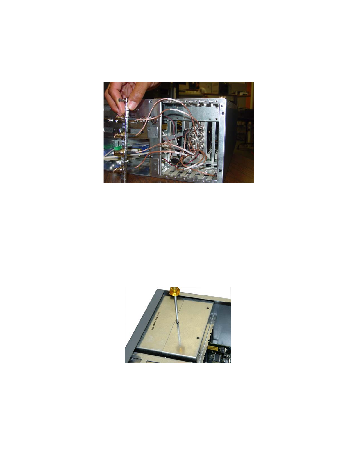
5. Remove all of the PCI slot back-panel access plates at the rear of the computer.
Unscrew the two spring screws that hold each plate in place, and then pry each plate from
the back of the computer. Note that internal BNC cables run from the back of the
workstation’s back-panel access plate for the TARGA card. Refer to Figure 5-3.
Figure 5-3: BNC I/O Connection Plate with internal BNC cables
Remove from the TARGA card the BNC cables coming from the workstation’s back-panel
access plate for the TARGA card.
6. Remove all remaining BNC cables from the TARGA card.
Remove all of the remaining BNC cables from the TARGA card (including the REF BNC
cable if it is used).
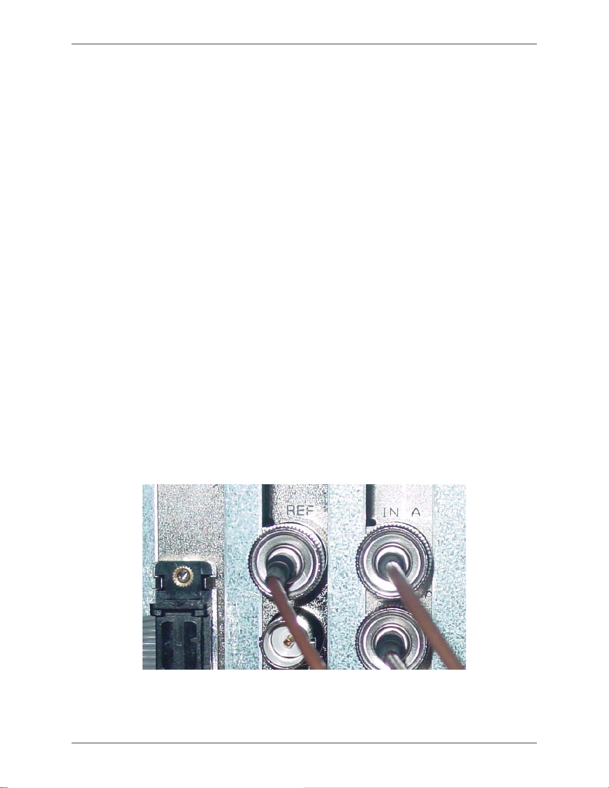
7. Remove the Fan Cover.
Refer to Figure 5-4. Unscrew the 3 retaining screws on top of the fan housing that holds the
fan’s cover in place. Then remove the fan cover and put it aside.
Figure 5-4: Fan Cover Retaining Screws
8. Remove the Workstation Support Brace.
The Workstation Support Brace lies across the workstation just above the TARGA card and
other workstation cards. Refer to Figure 5-1. There are two screws on each end of the brace
that must be unscrewed so that the support brace can be removed from the workstation.
46
DekoCast Technical Reference And Service Guide
Page 47
Chapter 5: System Maintenance
9. Remove retaining screw and pull the TARGA card from the PCI slot.
Unscrew the retaining screw that secures the TARGA card’s bracket in place. Save the
screw because it will be used with the new card. Firmly lift the TARGA card from its slot
by pulling upwards while using a gentle lengthwise rocking motion, and set the card aside.
10. Remove the new TARGA card from its antistatic bag.
Make sure you are grounded via the antistatic wrist strap. Handle the card by its edges and
by its metal bracket, and avoid touching the connector pins on the bottom of the card. If a
black handle is connected to the TARGA card, remove the handle so that the card looks
similar to that shown in Figure 5-2.
11. Insert the new TARGA card into the expansion slot.
Note: The same expansion slot that the damaged card was pulled from should be used.
With the bracket toward the open access port, align the connector on the bottom of the
card directly over the slot. Then push down and gently rock the card lengthwise until the
card is firmly seated. When pushed into the slot the TARGA card may catch as if it were
in place, so gently continue to exert pressure until it “seats” again. The gold slot
connectors on the card are barely visible when the card is completely installed.
Important: Don’t over force the card. If there is hard resistance, remove the card and try again.
12. Secure the TARGA card’s bracket with retaining screw.
Use the card retaining screw that was removed earlier to secure the TARGA card’s bracket
in place.
13. Attach the REF 1 internal BNC cable to the REF BNC connector on the TARGA
card.
Refer to Figure 5-5. Push the BNC cable grip onto the card’s BNC connector. The BNC
cable grip should then be turned clockwise to lock it onto the card’s BNC connector.
Figure 5-5: REF 1 internal cable connected to TARGA card
Note: All REF BNC’s are the same.
DekoCast Technical Reference And Service Guide
47
Page 48
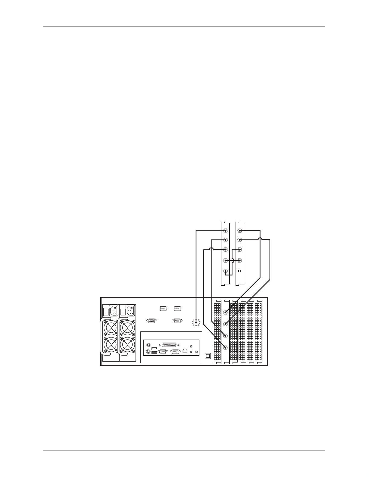
Chapter 5: System Maintenance
14. Attach all other internal BNC cables to the TARGA card.
The internal BNC connections to the TARGA card from the workstation’s back-panel
BNC I/O access plate for the TARGA card, and from the Daria Bypass Card, are as
follows:
Back-Panel I/O BNC Access Plate to TARGA:
• KEY IN to TARGA IN B
• KEY OUT to TARGA OUT B
Daria Bypass Card to TARGA:
• Daria OUT B to TARGA IN A
• Daria IN B to TARGA OUT A
The internal BNC connections from the workstations’s back-panel BNC I/O access plate
for the TARGA card to the Daria Bypass Card are as follows:
Back-Panel I/O BNC Access Plate to Daria:
• VIDEO IN to Daria IN A
• VIDEO OUT to Daria OUT A
A visual representation of the BNC connections is shown in Figure 5-6.
DARIA
Inside Of Workstation Chassis
REDUNDANT POWER SUPPLIES
SVGA
MOUSE
KEYBRD
RS422A RS422A
USB
SERIAL
PARALLEL
MANUAL
BYPASS
SERIAL
NETWORK
REFERENCE
SPEAKERS
ALARM
SILENCE
MIC
Figure 5-6: BNC Connections for TARGA and Daria Bypass Cards
TARGA
REF
IN B
OUT B
IN A
OUT A
VIDEO
IN
VIDEO
OUT
KEY
IN
KEY
OUT
IN A
OUT A
IN B
OUT B
OVER
RIDE
15. Attach all of the PCI slot back-panel access plates to the workstation.
Push each workstation PCI slot back-panel access plate into place on the computer’s
frame, and tighten the two spring screws of each plate to fasten. Then connect all of the
external BNC cables to the front of the BNC I/O Connection Plate. Make sure that the
external BNC cables that connect to the BNC I/O access plate for the TARGA card are
firmly in place.
48
DekoCast Technical Reference And Service Guide
Page 49

Chapter 5: System Maintenance
16. Attach the Fan Cover and Workstation Support Brace.
Place the Fan Cover on top of the fan housing and screw the cover back into place with the
three cover screws previously removed. Put the Workstation Support Brace back in place
just above the TARGA card(s) and other cards. Refer to Figure 5-1. Screw the brace into
place at both ends with its previously removed screws.
17. Attach all other cables and power up the computer.
Connect power cord, monitor cable, and any other communication cables that you
removed previously, and then power up the computer.
18. If necessary, set the termination switch on the TARGA Card.
The termination switch on the TARGA card is located near the top edge of the card close
to the card’s retainer bracket. Refer to Figure 5-7.
Figure 5-7: Termination switch on two TARGA cards
Some systems require the termination switch on the TARGA card to be “On,” others
“Off.” Termination is activated “On” if the switch is set away from the retainer bracket so
that the switch’s green LED light is lit (i.e., On).
Important: The TARGA card termination switch must be set to “On” in a DekoCast workstation.
19. Run the I/O Diagnostic Test to ensure the new card is functional.
The I/O Diagnostic T est application should be used to check the functionality of the newly
installed TARGA card. Refer to “Chapter 4: Tr oubleshooting” for instructions on locating
and using the Diagnostic Test software program.
Important: If the newly installed T ARGA card fails when tested, check all of the connections and
retest. If the card fails again, contact Pinnacle Customer Support. Refer to Appendix A for contact
information.
20. Place the computer’s cover back on the computer.
Use a Phillips-head (+) screwdriver to reattach the screws securing the top cover to the
computer.
21. Return the damaged TARGA Card to Pinnacle Systems.
Place the damaged TARGA card into the antistatic bag that the replacement card was
pulled from, and send the damaged card to Pinnacle Systems per the instructions given by
Pinnacle Support.
DekoCast Technical Reference And Service Guide
49
Page 50

Chapter 5: System Maintenance
Replacing The Daria Bypass Card
Important: Remove the Daria Bypass Card only if directed to do so by a Pinnacle Systems Customer
Support representative.
There is one Daria Bypass Card within a DekoCast W orkstation. Refer to Figure 5-1 for the Daria
Bypass Card location, and Figure 5-8 for Daria Bypass Card identification.
Figure 5-8: Daria Bypass Card
1. Shut down the computer and turn off the monitor.
Shut down the computer by going to the Start menu and selecting Shut Down (Start menu
>> Shut Down). Turn off the monitor after you are sure the computer has powered down.
Important: Do not attempt to open the computer while the computer is turned on. If you think the
computer is in sleep mode press the power button in front of the computer to wake it, and then shut
down the computer.
2. Remove all cables from the back of the computer, and let the computer cool down.
Unplugging the power cord and cables helps to ensure that no power is running on the
motherboard, which reduces the risk of damage to your equipment. W ait 5 minutes to allow
the computer’s internal components to cool.
3. Discharge static electricity that you may have on your clothes or body.
Use the Anti-Static Wrist Strap that is provided with your new Daria Bypass Card. Also,
touch the metal part of the power supply to discharge any static electric charge that you
might be carrying.
4. Remove the top cover from the computer.
Use a Phillips-head (+) screwdriver to remove the screws attaching the top cover to the
computer. Then remove the cover from the computer.
5. Except for the BNC back-panel access plate, remove all the other PCI slot back-panel
access plates at the rear of the computer.
Unscrew the two spring screws that hold each plate in place, and then pry each plate from
the back of the computer. Note that internal BNC cables run from the back of the BNC
back-panel access plate to the Daria Bypass Card. Refer to Figure 5-9.
50
DekoCast Technical Reference And Service Guide
Page 51

Chapter 5: System Maintenance
Figure 5-9: View of BNC cables connected to Daria Bypass Card
6. Remove all the BNC cables from the Daria Bypass Card.
Disconnect the four BNC cables from the Daria Bypass Card. Each BNC cable “grip” must
be turned counter-clockwise to loosen. Once loosened, a BNC can be pulled from the
Daria’s BNC connector.
7. If the Over-Ride socket on the Daria has a plug in it, remove the plug.
The Over-Ride socket is located at the bottom of the Daria’s card mounting bracket. If an
over-ride switch has been installed on the workstation, remove the plug for the switch from
the Daria Bypass Card.
8. Remove the Workstation Support Brace.
The Workstation Support Brace lies across the workstation just above the Daria Bypass
Card and other workstation cards. Refer to Figure 5-1. There are two screws on each end of
the brace that must be unscrewed so that the support brace can be removed from the
workstation.
9. Remove retaining screw and pull the Daria Bypass Card from the PCI slot.
Unscrew the retaining screw that secures the Daria Bypass Card’ s bracket in place. Save the
screw because it will be used with the new card. Firmly lift the Daria Bypass Card from its
slot by pulling upwards while using a gentle lengthwise rocking motion, and set the card
aside.
10. Remove the new Daria Bypass Card from its antistatic bag.
Make sure you are grounded via the antistatic wrist strap. Handle the card by its edges and
by its metal bracket, and avoid touching the connector pins on the bottom of the card.
11. Insert the new Daria Bypass Card into the expansion slot.
Note: The same expansion slot that the damaged card was pulled from should be used.
With the bracket toward the open access port, align the connector on the bottom of the
card directly over the slot. Then push down and gently rock the card lengthwise until the
card is firmly seated. .
Important: Don’t over force the card. If there is hard resistance, remove the card and try again.
DekoCast Technical Reference And Service Guide
51
Page 52

Chapter 5: System Maintenance
12. Secure the Daria Bypass Card’s bracket with retaining screw.
Use the card retaining screw that was removed earlier to secure the bracket in place.
13. Attach all four internal BNC cables to the Daria Bypass Card.
The internal BNC connections to the Daria Bypass Card from the workstation’s backpanel BNC
I/O access plate, and from the Daria Bypass Card, are as follows:
Back-Panel I/O BNC Access Plate to Daria:
• VIDEO IN to Daria IN A
• VIDEO OUT to Daria OUT A
Daria Bypass Card to TARGA:
• TARGA IN A to Daria OUT B
• TARGA OUT A to Daria IN B
Refer to Figure 5-6 for a visual representation of the BNC connections.
14. If an Over-Ride switch is installed on the workstation, connect the plug into the
socket on the Daria Bypass Card.
The Over-Ride socket is located at the bottom of the Daria’s card mounting bracket.
15. Attach all of the PCI slot back-panel access plates to the workstation.
Push each workstation PCI slot back-panel access plate into place on the computer’s
frame, and tighten the two spring screws of each plate to fasten. Then connect all of the
external BNC cables to the front of the BNC I/O Connection Plate. Make sure that the
external BNC cables that connect to the BNC I/O access plate are firmly in place.
16. Attach the Workstation Support Brace.
Put the W orkstation Support Brace back in place just above the cards. Refer to Figure 5-1.
Screw the brace into place at both ends with its previously removed screws.
17. Attach all other cables and power up the computer.
Connect power cord, monitor cable, and any other communication cables that you
removed previously, and then power up the computer.
18. Place the computer’s cover back on the computer.
Use a Phillips-head (+) screwdriver to reattach the screws securing the top cover to the
computer.
19. Return the damaged Daria Bypass Card to Pinnacle Systems.
52
Place the damaged Daria Bypass Card into the antistatic bag that the replacement card was
pulled from, and send the damaged card to Pinnacle Systems per the instructions given by
Pinnacle Support.
DekoCast Technical Reference And Service Guide
Page 53

Chapter 5: System Maintenance
Replacing The RS-422 Card
Important: Remove the RS-422 card only if directed to do so by a Pinnacle Systems Customer Support
representative.
There is one RS-422 card within a DekoCast Workstation. Refer to Figure 5-1 for the RS-422
card location, and Figure 5-10 for Daria Bypass Card identification.
Figure 5-10: RS-422 Card
1. Shut down the computer and turn off the monitor.
Shut down the computer by going to the Start menu and selecting Shut Down (Start menu
>> Shut Down). Turn off the monitor after you are sure the computer has powered down.
Important: Do not attempt to open the computer while the computer is turned on. If you think the
computer is in sleep mode press the power button in front of the computer to wake it, and then shut
down the computer.
2. Remove all cables from the back of the computer, and let the computer cool down.
Unplugging the power cord and cables helps to ensure that no power is running on the
motherboard, which reduces the risk of damage to your equipment. W ait 5 minutes to allow
the computer’s internal components to cool.
3. Discharge static electricity that you may have on your clothes or body.
Use the Anti-Static Wr ist Strap that is provided with your new RS-422 card. Also, touch the
metal part of the power supply to discharge any static electric charge that you might be
carrying.
4. Remove the top cover from the computer.
Use a Phillips-head (+) screwdriver to remove the screws attaching the top cover to the
computer. Then remove the cover from the computer.
5. Except for the BNC back-panel access plate, remove all the other PCI slot back-panel
access plates at the rear of the computer.
Unscrew the two spring screws that hold each plate in place, and then pry each plate from
the back of the computer. Note that internal ribbon cables run from the back panel of the
workstation chassis to the RS-422 card. Refer to Figure 5-11.
DekoCast Technical Reference And Service Guide
53
Page 54

Chapter 5: System Maintenance
Figure 5-11: View of ribbon cables connected to RS-422 card
6. Remove the ribbon cables from the RS-422 card.
Disconnect the two ribbon cables from the RS-422 card.
7. Remove the Workstation Support Brace.
The Workstation Support Brace lies across the workstation just above the RS-422 card and
other workstation cards. Refer to Figure 5-1. There are two screws on each end of the brace
that must be unscrewed so that the support brace can be removed from the workstation.
8. Remove retaining screw and pull the RS-422 card from the PCI slot.
Unscrew the retaining screw that secures the RS-422 card’ s bracket in place. Save the screw
because it will be used with the new card. Firmly lift the RS-422 card from its slot by
pulling upwards while using a gentle lengthwise rocking motion, and set the card aside.
9. Remove the new RS-422 card from its antistatic bag.
Make sure you are grounded via the antistatic wrist strap. Handle the card by its edges and
by its metal bracket, and avoid touching the connector pins on the bottom of the card.
10. Insert the new RS-422 card into the expansion slot.
Note: The same expansion slot that the damaged card was pulled from should be used.
With the bracket toward the open access port, align the connector on the bottom of the
card directly over the slot. Then push down and gently rock the card lengthwise until the
card is firmly seated. .
Important: Don’t over force the card. If there is hard resistance, remove the card and try again.
11. Secure the RS-422 card’s bracket with retaining screw.
Use the card retaining screw that was removed earlier to secure the bracket in place.
54
DekoCast Technical Reference And Service Guide
Page 55

Chapter 5: System Maintenance
12. Attach the two internal ribbon cables to the RS-422 card.
The internal ribbon connections to the RS-422 card from the workstation’ s back-panel RS422 connections are as follows:
• Workstation Back-Panel RS-422A ribbon to bottom connector on RS-422 Card
• Workstation Back-Panel RS-422B ribbon to top connector on RS-422 Card
Note: The easiest way to tell which ribbon cable is which is to insert your fingers inside the back-panel
chassis to the RS-422B connector, and then trace the ribbon cable with your fingers.
13. Attach the PCI slot back-panel access plates to the workstation.
Push each workstation PCI slot back-panel access plate into place on the computer’s
frame, and tighten the two spring screws of each plate to fasten. Then connect all of the
external BNC cables to the front of the BNC I/O Connection Plate.
14. Attach the Workstation Support Brace.
Put the W orkstation Support Brace back in place just above the cards. Refer to Figure 5-1.
Screw the brace into place at both ends with its previously removed screws.
15. Attach all other cables and power up the computer.
Connect power cord, monitor cable, and any other communication cables that you
removed previously, and then power up the computer.
16. Place the computer’s cover back on the computer.
Use a Phillips-head (+) screwdriver to reattach the screws securing the top cover to the
computer.
17. Return the damaged RS-422 Card to Pinnacle Systems.
Place the damaged Daria Bypass Card into the antistatic bag that the replacement card was
pulled from, and send the damaged card to Pinnacle Systems per the instructions given by
Pinnacle Support.
DekoCast Technical Reference And Service Guide
55
Page 56

Chapter 5: System Maintenance
Replacing The SVGA Card
Important: Remove a SVGA card only if directed to do so by a Pinnacle Systems Customer Support
representative.
The SVGA card is installed in the AGP slot on the motherboard. The AGP slot is brown in color;
the PCI slots are ivory in color. Refer to Figure 5-1 for the SVGA card location, and Figure 5-12
for SVGA card identification.
Figure 5-12: SVGA Card
Note: The workstation SVGA card may differ slightly from what is shown in Figure 5-12.
1. Shut down the computer and turn off the monitor.
Shut down the computer by going to the Start menu and selecting Shut Down (Start menu
>> Shut Down). Turn off the monitor after you are sure the computer has powered down.
Important: Do not attempt to open the computer while the computer is turned on. If you think the
computer is in sleep mode press the power button in front of the computer to wake it, and then shut
down the computer.
2. Remove all cables from the back of the computer, and let the computer cool down.
Unplugging the power cord and cables helps to ensure that no power is running on the
motherboard, which reduces the risk of damage to your equipment. Be sure to disconnect
the monitor’s VGA cable (Figure 5-13).
56
Figure 5-13: Monitor cable connected to SVGA card.
DekoCast Technical Reference And Service Guide
Page 57

Chapter 5: System Maintenance
3. Discharge static electricity that you may have on your clothes or body.
Use the Anti-Static Wrist Strap that is provided with your DekoCast Workstation. Also,
touch the metal part of the power supply to discharge any static electric charge that you
might be carrying.
4. Remove the top cover from the computer.
Use a Phillips-head (+) screwdriver to remove the screws attaching the top cover to the
computer. Then remove the cover from the computer.
5. Remove the Workstation Support Brace.
The Workstation Support Brace lies across the workstation just above the TARGA card(s)
and other workstation cards. Refer to Figure 5-1. There are two screws on each end of the
brace that must be unscrewed so that the brace can be removed from the workstation.
6. Remove SVGA card’s retaining screws and pull the card from the AGP slot.
Unscrew the retaining screws that secures the SVGA card’s bracket in place. Save the
screws because they will be used with the new card. There may be a retention clip built into
the AGP slot (towards the end). If so you must push it aside, then firmly lift the SVGA card
from its slot by pulling upwards while using a gentle lengthwise rocking motion.
Note: If there is a tie wrap binding the wiring, you may have to remove (i.e., cut) the tie wrap.
7. Remove the new SVGA card from its antistatic bag.
Make sure you are grounded via the antistatic wrist strap. Handle the card by its edges and
by its metal bracket, and avoid touching the connector pins on the bottom of the card.
8. Insert the new SVGA card into the AGP slot.
With the bracket toward the open access port, align the connector on the bottom of the card
directly over the slot. Then push down and gently rock the card lengthwise until the card is
firmly seated.
Important: Don’t over force the card. If there is hard resistance, remove the card and try again.
9. Attach the Workstation Support Brace.
Put the Workstation Support Brace back in place just above the TARGA card(s) and other
cards. Refer to Figure 5-1. Screw the brace into place at both ends with its previously
removed screws.
10. Attach all other cables to the computer.
Connect power cord, SVGA monitor cable, and any other communication cables that you
previously removed.
11. Turn on the monitor and power up the computer
You should see video displayed on the VGA monitor.
Important: If video is not displayed on the VGA monitor, check all of the connections. If is still
not displayed, contact Pinnacle Customer Support. Refer to Appendix A for contact information.
DekoCast Technical Reference And Service Guide
57
Page 58

Chapter 5: System Maintenance
12. Place the computer’s cover back on the computer.
Use a Phillips-head (+) screwdriver to reattach the screws securing the top cover to the
computer.
13. Return the damaged SVGA Card to Pinnacle Systems.
Place the damaged SVGA card into the antistatic bag that the replacement card was pulled
from, and send the damaged card to Pinnacle Systems per the instructions given by
Pinnacle Support.
Replacing A Hard Drive
Important: Remove a Hard Drive only if directed to do so by a Pinnacle Systems Customer Support
representative.
The Hard Drives are accessed from the front panel of a DekoCast Workstation if it becomes
necessary to install a replacement. Refer to Figure 5-14.
Figure 5-14: Workstation Front Panel (with panel cover removed)
Refer to Figure 5-15 for Hard Drive identification.
Figure 5-15: DekoCast Workstation Hard Drive
1. Shut down the computer and turn off the monitor.
Shut down the computer by going to the Start menu and selecting Shut Down (Start menu
>> Shut Down). Turn off the monitor after you are sure the computer has powered down.
Important: Do not attempt to open the computer while the computer is turned on. If you think the
computer is in sleep mode press the power button in front of the computer to wake it, and then shut
down the computer.
58
DekoCast Technical Reference And Service Guide
Page 59

Chapter 5: System Maintenance
2. Discharge static electricity that you may have on your clothes or body.
Use the Anti-Static Wrist Strap that is provided with your DekoCast Workstation. Also,
touch the metal part of the power supply to discharge any static electric charge that you
might be carrying.
3. Loosen the captive thumbscrews of the damaged drive.
Use a screwdriver if necessary to completely loosen the two thumbscrews. The screws are
“captive” meaning that they can be loosened but not removed from the front bay panel.
4. Pull the Hard Drive out from its drive bay.
Grab the two thumbscrews and pull to slide the Hard Drive out from the drive bay . Refer to
Figure 5-16.
Figure 5-16: Hard drive out from drive bay.
Continue to pull on the Hard Drive until it is completely removed from its drive bay. Refer
to Figure 5-17. Set the damaged Hard Drive aside.
Figure 5-17: View of empty hard drive bay
DekoCast Technical Reference And Service Guide
59
Page 60

Chapter 5: System Maintenance
5. Remove the new Hard Drive from its antistatic bag.
Make sure you are grounded via the antistatic wrist strap. Handle the new Hard Drive as
much as possible by its front bay panel.
6. Push the new Hard Drive all the way into the drive bay.
Align the Hard Drive so that it will properly slide into the drive bay, and then push the Hard
Drive so that it completely slides into the drive bay. This will connect the Hard Drive to its
connectors at the back of the bay. Refer to Figure 5-16. The Hard Drive’s front bay panel
should be flush with the front panel of the DekoCast Workstation.
7. Tighten the captive thumbscrews of the new drive.
Use a screwdriver if necessary to completely tighten the two thumbscrews.
8. Turn on the monitor and power up the computer
You should see video displayed on the VGA monitor.
Important: If an “Operating system not found” message is displayed on the monitor, the captive
thumbscrews for the new drive may not be tighten enough. Use a screwdriver to tighten the screws
as much as possible, and then power down and power up the workstation.
Important: If video is not displayed on the VGA monitor, check all of the connections. If is still not
displayed, contact Pinnacle Customer Support. Refer to Appendix A for contact information.
9. Configure the new hard drive.
Refer to either “Configuring A New System Hard Drive” or “Configuring A New Media
Hard Drive” in this Chapter for information on configuring the new Hard Drive just
installed.
10. Place backup files from damaged hard drive onto the new hard drive.
Refer to “System Recovery Procedures” in this Chapter for information on placing the
files backed up from the damaged Hard Drive onto the new Hard Drive just installed.
Important: If there is no backup of the damaged Hard Drive, co ntact Pinnacle Cust omer Support .
Refer to Appendix A for contact information.
11. Return the damaged Hard Drive to Pinnacle Systems.
Place the damaged Hard Drive into the antistatic bag that the replacement drive was pulled
from, and send the damaged drive to Pinnacle Systems per the instructions given by
Pinnacle Support.
60
DekoCast Technical Reference And Service Guide
Page 61

Chapter 5: System Maintenance
Replacing A Power Supply
Important: Remove a Power Supply only if directed to do so by a Pinnacle Systems Customer Support
representative.
The DekoCast Workstation uses a dual Power Supply configuration. This redundancy with the
power supplies is so if one Power Supply should fail the other will keep the workstation from
abruptly powering down. When a DekoCast Workstation Power Supply unit starts to
malfunction, the LED on the unit will dim and eventually turn off. A Workstation Power Supply
unit is shown in Figure 5-18.
Figure 5-18: Power Supply
The Power Supplies are accessed from the back of a DekoCast Workstation if it becomes
necessary to install a replacement. A Power Supply can be replaced “hot.” That is, a Power
Supply can be replaced while the DekoCast is powered up (i.e., turned on and running).
1. Switch damaged Power Supply to off position and unplug it.
Make sure the switch of the Power Supply to be removed is in the off (i.e., “0”) position, and
its power cord is removed. Refer to Figure 5-19.
Figure 5-19: Power Supply ready to be removed.
DekoCast Technical Reference And Service Guide
Locking
Latches
61
Page 62
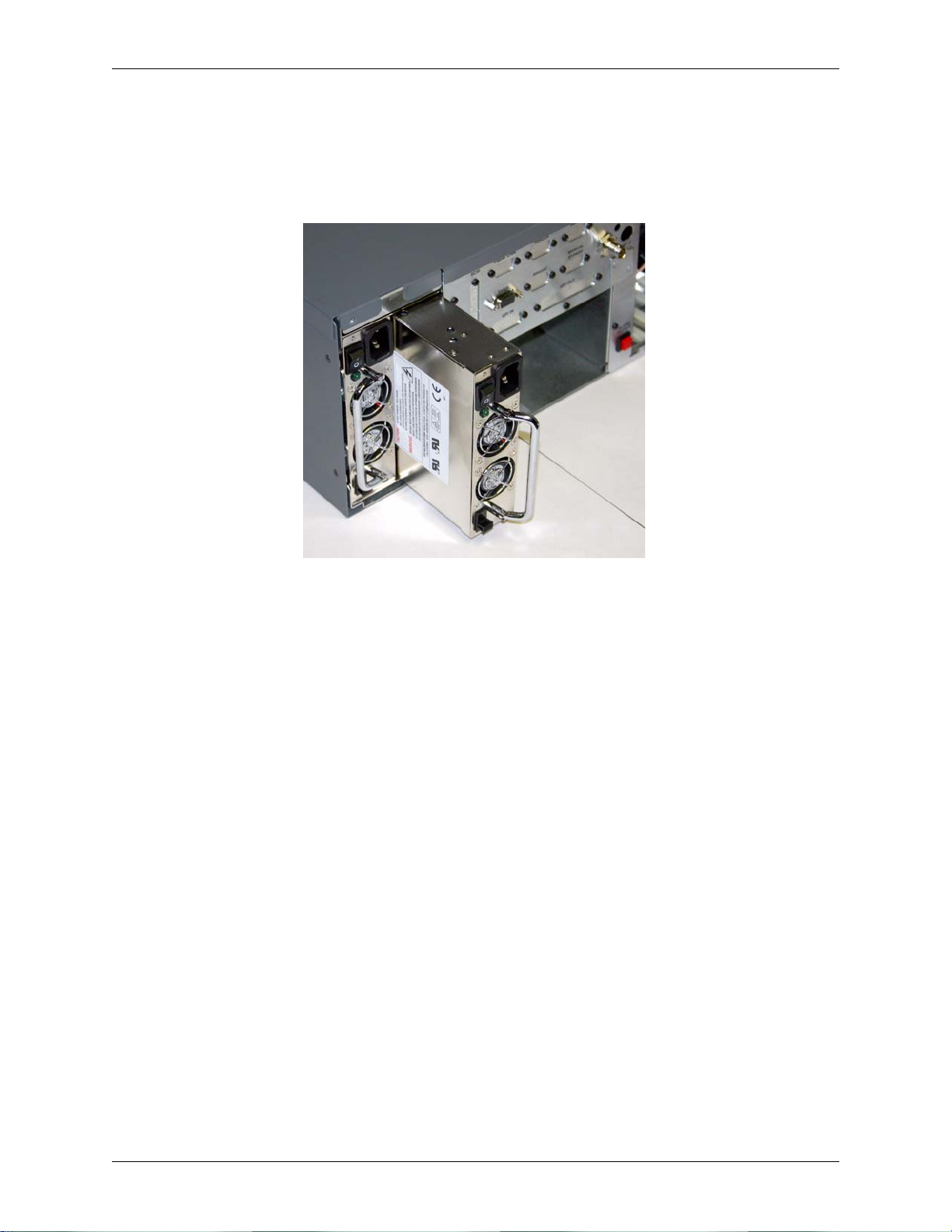
Chapter 5: System Maintenance
2. Release locking latch and pull the Power Supply from the DekoCast Workstation.
Slide the locking latch (see Figure 5-19) switch up to release the lock. Then grab the Power
Supply unit’s handle and pull the Power Supply straight out from the workstation. Refer to
Figure 5-20. Set the damaged unit aside.
Figure 5-20: Hard drive out from drive bay.
3. Remove the new Power Supply from its antistatic bag.
Handle the new Power Supply with care.
4. Push the new Power Supply all the way into the drive bay.
Align the Power Supply so that it will properly slide into its bay, slide the locking latch up,
and then push the Power Supply so that it completely slides into the bay. This will connect
the Power Supply to its connectors at the back of the bay . Make sure the locking latch slides
down to lock the Power Supply into place.
5. Plug in power cord and switch Power Supply to On.
When the Power Supply is switched to the On (i.e., “1”) position, its LED should light.
Important: If the LED on the unit does not light, check both ends of the unit’s power cord and also
make sure the workstation is turned on as well. If the LED still does not light and you are sure the
unit is receiving power and the workstation is on, contact Pinnacle Customer Support. Refer to
Appendix A for contact information.
6. Return the damaged Power Supply to Pinnacle Systems.
Place the damaged Power Supply into the antistatic bag that the replacement unit was pulled
from, and send the damaged unit to Pinnacle Systems per the instructions given by Pinnacle
Support.
62
DekoCast Technical Reference And Service Guide
Page 63

Chapter 5: System Maintenance
Replacing The Fan
Important: Remove the Fan in a DekoCast W orkstation only if directed to do so by a Pinnacle Systems
Customer Support representative.
The Fan assembly is located at the front of a DekoCast Workstation next to the Hard Drives
(opposite side from DVD/CD and Floppy drive). Specifically , the Fan assembly is located directly
in front of the T ARGA card(s). The primary function of the Fan is to help regulate the temperature
of the TARGA card(s). Refer to Figure 5-1 for the Fan assembly location, and Figure 5-21 for
Fan identification.
Figure 5-21: DekoCast Workstation Fan
1. Shut down the computer and turn off the monitor.
Shut down the computer by going to the Start menu and selecting Shut Down (Start menu
>> Shut Down). Turn off the monitor after you are sure the computer has powered down.
Important: Do not attempt to open the computer while the computer is turned on. If you think the
computer is in sleep mode press the power button in front of the computer to wake it, and then shut
down the computer.
2. Remove all cables from the back of the computer, and let the computer cool down.
Unplugging the power cord and cables helps to ensure that no power is running on the
motherboard, which reduces the risk of damage to your equipment. W ait 5 minutes to allow
the computer’s internal components to cool.
3. Discharge static electricity that you may have on your clothes or body.
Use the Anti-Static Wrist Strap that is provided with your DekoCast Workstation. Also,
touch the metal part of the power supply to discharge any static electric charge that you
might be carrying.
4. Remove the top cover from the computer.
Use a Phillips-head (+) screwdriver to remove the screws attaching the top cover to the
computer. Then remove the cover from the computer.
5. Remove the Workstation Support Brace, Fan Cover, and TARGA card(s).
Because the TARGA card(s) block the Fan Box screw access holes for the Fan, the TARGA
card(s) must be removed from their slot(s). The Workstation Support Brace and Fan Cover
must be removed as well. Refer to the “Replacing A TARGA Card” section previously
discussed in this Chapter for instructions on removing the Workstation Support Brace, Fan
Cover, and TARGA card(s).
DekoCast Technical Reference And Service Guide
63
Page 64

Chapter 5: System Maintenance
6. Disconnect the Fan’s power connector.
Disconnect the Fan’s power connector. Refer to Figure 5-22. If there is a tie binding the
Fan’s power connector wiring to other wiring in the workstation, cut the tie and remove it.
The wiring and connector for the Fan will come out of the workstation with the Fan when
the Fan is lifted from the Fan Box.
Figure 5-22: Workstation Fan Connector
7. Remove the 4 screws that secure the Fan within the Fan Box.
There are access holes in the Fan Box that provide access to the fan retaining screws. Refer
to Figure 5-23. Use a screw driver to loosen or remove each screw so that the Fan can be
lifted out the top of the Fan Box.
Note: A magnetic screwdriver may be needed to more easily remove the fan screws.
Figure 5-23: Access Holes To Fan Retaining Screws
8. Lift the Fan out of the workstation Fan Box.
Once the 4 screws are no longer securing the fan in place, the fan can be lifted straight out
from the top of the Fan Box. There is an opening inside the Fan Box from which the Fan’s
wiring and power connector can be pulled through in order to completely remove the Fan
from the workstation.
64
DekoCast Technical Reference And Service Guide
Page 65

Chapter 5: System Maintenance
9. Insert the new Fan’s power connector and wiring into the workstation.
Place the new Fan’s wiring and power connector into the Fan Box and snake it through the
opening at the bottom of the box so that both are inside of the workstation chassis.
10. Insert new Fan into the workstation Fan Box and secure in place.
Place the new Fan into the Fan Box and secure it in place with the 4 screws that were
previously removed. Refer to Figure 5-23. A magnetic screwdriver or turning the
workstation up on its end may be necessary in order to align the screws to the screw holes.
11. Connect the Fan’s power connector.
Connect the Fan’s power connector so that power will be supplied to the Fan when the
workstation is powered up
12. Reinsert the TARGA cards into their slots, and reconnect their BNC cables.
Refer to “Replacing A TARGA Card” section previously discussed in this Chapter.
13. Attach the Fan Cover and Workstation Support Brace.
Place the Fan Cover on top of the fan housing and screw the cover back into place with the
three cover screws previously removed. Put the Workstation Support Brace back in place
just above the TARGA card(s) and other cards. Refer to Figure 5-1. Screw the brace into
place at both ends with its previously removed screws.
14. Attach all other cables to the computer.
Connect power cord and any other communication cables that you previously removed
from the DekoCast Workstation.
15. Turn on the monitor and power up the computer
You should see video displayed on the VGA monitor, and the new Fan should be working.
Important: If video is not displayed on the VGA monitor or if the new Fan is not working, then
check all of the connections. If video is still not displayed or if the Fan still is not working, then
contact Pinnacle Customer Support. Refer to Appendix A for contact information.
16. Place the computer’s cover back on the computer.
Use a Phillips-head (+) screwdriver to reattach the screws securing the top cover to the
computer.
17. Return the damaged Fan to Pinnacle Systems.
Send the damaged Fan to Pinnacle Systems per the instructions given by Pinnacle
Support.
DekoCast Technical Reference And Service Guide
65
Page 66

Chapter 5: System Maintenance
Replacing The DVD/CD Drive And/Or Floppy Drive
Important: Remove the DVD/CD Drive or Floppy Drive only if directed to do so by a Pinnacle
Systems Customer Support representative.
The DVD/CD and Floppy Drive assembly is located at the front of a DekoCast Workstation next
to the Hard Drives (opposite side from Fan). Refer to Figure 5-1 for the DVD/CD and Floppy
Drive assembly location, and Figure 5-24 for DVD/CD and Floppy Drive assembly identification.
Figure 5-24: DVD/CD and Floppy Drive Assembly
1. Shut down the computer and turn off the monitor.
Shut down the computer by going to the Start menu and selecting Shut Down (Start menu
>> Shut Down). Turn off the monitor after you are sure the computer has powered down.
Important: Do not attempt to open the computer while the computer is turned on. If you think the
computer is in sleep mode press the power button in front of the computer to wake it, and then shut
down the computer.
2. Remove all cables from the back of the computer, and let the computer cool down.
Unplugging the power cord and cables helps to ensure that no power is running on the
motherboard, which reduces the risk of damage to your equipment. W ait 5 minutes to allow
the computer’s internal components to cool.
3. Discharge static electricity that you may have on your clothes or body.
Use the Anti-Static Wrist Strap that is provided with your DekoCast Workstation. Also,
touch the metal part of the power supply to discharge any static electric charge that you
might be carrying.
4. Remove the top cover from the computer.
Use a Phillips-head (+) screwdriver to remove the screws attaching the top cover to the
computer. Then remove the cover from the computer.
66
DekoCast Technical Reference And Service Guide
Page 67

Chapter 5: System Maintenance
5. Disconnect the 2 thick-wired USB connectors on motherboard that come from the
DVD/CD and Floppy Drive assembly.
Grasp each connector for the two USB wires and pull each from the motherboard. Refer to
Figure 5-25.
Figure 5-25: Dual-wired USB connector on motherboard
6. Disconnect the power connector and ribbon cable from back of the DVD/CD Drive.
Pull the longer motherboard ribbon connector and then the power connector from the back
of the DVD/CD Drive. Refer to Figure 5-26.
Figure 5-26: Motherboard ribbon and power cables connected to DVD/CD and Floppy Drive
7. Disconnect the power connector and ribbon cable from back of the Floppy Drive.
Pull the other (i.e., shorter) motherboard ribbon connector and then the power connector
from the back of the Floppy Drive. Refer to Figure 5-26.
8. Remove the 4 screws from front panel that secures the DVD/CD Floppy Assembly.
There is one front panel screw at each edge DVD /D Floppy assembly (for a total of 4
screws) that holds the assembly to the front panel of the workstation. Remove these 4
screws and set them aside.
DekoCast Technical Reference And Service Guide
67
Page 68

Chapter 5: System Maintenance
9. Push the DVD/CD Floppy Assembly from the back to slide it out of the workstation.
Push the assembly from its back, and then grab its front to slide it out of the workstation.
Take care that the dual-wire USB cable does not snag or pull other connected wires loose
when the assembly is being removed. Refer to Figure 5-27.
Figure 5-27: Removal of DVD/CD and Floppy Drive
10. If the DVD/CD Drive is to be replaced, remove the screws securing the DVD/CD
Drive in the DVD/CD Floppy housing assembly.
There are 2 screws on the top side of the housing and 2 screws on the bottom side of the
housing that keeps the DVD/CD Drive in place. Refer to Figure 5-28. Remove the
screws.
Figure 5-28: Bottom of DVD/CD Floppy housing assembly
1 1. If the Floppy Drive is to be replaced, remove the screws securing the Floppy Drive in
the DVD/CD Floppy housing assembly.
There are 4 screws on the top of the housing and 4 screws on the bottom of the housing
that keeps the Floppy Drive in place. Refer to Figure 5-28. Remove the screws.
12. Remove the malfunctioning drive from the housing assembly, and replace with the
new DVD/CD or Floppy drive.
Once the malfunctioning DVD/CD or Floppy drive’s securing screws have been removed
from the housing assembly, the drive can simply be pushed out of the front of the housing
68
DekoCast Technical Reference And Service Guide
Page 69

Chapter 5: System Maintenance
assembly. The new replacement drive can then be pushed into the front of the assembly
until it is in place. Refer to Figure 5-29.
Figure 5-29: Inserting DVD/CD Floppy housing assembly back into workstation
13. Put the screws that were removed back into the housing assembly.
Align the screw holes, and secure the new drive to the housing assembly with the screws
that were previously removed.
14. Connect the power connector and ribbon cable into the back of the Floppy Drive.
Connect the shorter motherboard ribbon connector and then the power connector to the
back of the Floppy Drive. Refer to Figure 5-26.
15. Connect the power connector and ribbon cable to the back of the DVD/CD Drive.
Connect the longer motherboard ribbon connector and then the power connector to the
back of the DVD/CD Drive. Refer to Figure 5-26.
16. Connect the 2 thick-wired USB connectors to the motherboard that come from the
DVD/CD and Floppy Drive assembly.
Dress the two USB wires under the TARGA board. Then connect each connector to the
pins shown in Figure 30.
Important: The red wires go toward the PCI slots and the rear panel. The black wires are toward
the fan. Refer to Figure 5-30.
Figure 5-30: Dual-wired USB connector on motherboard
DekoCast Technical Reference And Service Guide
69
Page 70

Chapter 5: System Maintenance
17. Attach all other cables to the computer.
Connect power cord and any other communication cables that you previously removed
from the DekoCast Workstation.
18. Power up the computer
You should see video displayed on the VGA monitor.
Important: If the DVD/CD or Floppy Drive LED light comes on and stays on, then the drive’s
ribbon cable has been connected upside down. If such is the case, shut down the workstation and
reattach the offending ribbon cable. If video is not displayed on the VGA monitor, then check all
of the connections. If video is still not displayed, then contact Pinnacle Customer Support. Refer
to Appendix A for contact information.
19. Place the computer’s cover back on the computer.
Use a Phillips-head (+) screwdriver to reattach the screws securing the top cover to the
computer.
20. Return the damaged DVD/CD Drive or Floppy Drive to Pinnacle Systems.
Send the damaged DVD/CD Drive or Floppy Drive to Pinnacle Systems per the
instructions given by Pinnacle Support.
70
DekoCast Technical Reference And Service Guide
Page 71

Chapter 5: System Maintenance
System Recovery Procedures
There may be instances when something happens and the DekoCast operating system (OS)
software (or Deko program software) gets so corrupted that the quickest and easiest fix is to wipe
out the OS and then restore it onto the workstation. There may be other instances where a
Pinnacle Systems Customer Support representative instructs you to replace the DekoCast OS and
Deko program software. In instances such as these, replacing the DekoCast system and program
software restores the workstation to the state it was in when it was initially shipped.
Note: The DekoCast program software must always be re-installed on the wo rkstation after the OS has been
restored.
Important: Because of instances such as the ones pointed out above, Pinnacle Systems always
recommends that you periodically back up your system and media (clip) drives.
Follow one of the criteria below that describes your situation:
-- If you have a DekoCast “Drive Image Restore DVD” and a DekoCast “Software CD” (both
ship with DekoCast workstations) stored in a place where you can find them per the
instructions given in “Chapter 2: Installation And Setup,” then proceed to the section “You
Have The Software Disks supplied By Pinnacle Systems” below. You will be able to
completely restore your workstation in about 20 minutes.
-- If you don’t have the DekoCast “Drive Image Restore DVD,” but you do have the DekoCast
Software CD, then proceed to the section called “Recreating A DekoCast Drive Image
Restore DVD” below. Pinnacle Systems has provided a way for you to create the “Drive
Image Restore DVD” that is needed from the DekoCast Workstation.
-- If you can’t find the DekoCast “Software CD,” then contact Pinnacle Systems Customer
Support to obtain the software. Contact information for Pinnacle Systems Customer Support
can be found in “Appendix A: Pinnacle Systems Customer Support.”
Important: If your system can’t boot back or if you have misplaced your Drive Image Restore
DVD, then contact Pinnacle Systems Customer Support.
You Have The Software Disks Supplied By Pinnacle Systems
Perform the following steps to restore a DekoCast OS:
Important: This process will permanently delete all of the material on your C: Drive. Be sure to
back up all important material on your C: Drive before proceeding with this process.
1. Enter the BIOS setup of the workstation.
If the workstation has been turned off, power it up. Enter the BIOS program by rebooting
the workstation, and then at the beginning of the start-up procedure press and momentarily
hold down the <F2> key on the keyboard. This is done when you see the words “Press
<F2> for Setup” on the monitor, or when you see the three keyboard “Lock” LEDs (top
right-hand corner of the keyboard) flash on the keyboard.
DekoCast Technical Reference And Service Guide
71
Page 72

Chapter 5: System Maintenance
2. Insert the “Drive Image Restore DVD” into the DVD/CD-ROM drive.
3. From within the BIOS display, check that the boot order for the drives is as follows:
Boot Menu
Silent Boot [Disabled]
Intel(R) Rapid BIOS Boot [Enabled]
PXE Boot to LAN [Disabled]
USB Boot [Disabled]
Boot Device Priority
1st Boot Device [1st Floppy Drive]
2nd Boot Device [3M-TEAC DV-W58G]
3rd Boot Device [PM-ST380013AS]
Hard Disk Drives Submenu
1st Drive [PM-ST380013AS]
2nd Boot Device [SM-ST3160023AS]
Important: The Har d Disk Drives Submenu must be in the o rder specified above. If not, yo ur Media
(i.e., Clip) drive will be overwritten and not the System drive.
Use the arrow keys to get to the Boot menu. If it is necessary to correct the order of the
drives, change the order of the drives per the instructions given on the screen. When you’re
done, be sure to Save and Exit the BIOS program.
4. Reboot the workstation (it may automatically reboot coming out of the BIOS).
You will see a prompt “Restoring will overwrite your system partition. Are you sure?
Important: This process will permanently delete all of the material on your C: Drive. Be sure to
back up all important material on your C: Drive before proceeding with this process.
Select “Yes.” The Drive Image Restore program will take approximately 6 minutes to
complete. After the program has finished, the root directory for Drive A (shown as A:\>)
will be displayed.
5. Remove the “Drive Image Restore DVD” from the DVD drive and reboot the workstation.
A welcome screen will appear after the reboot.
6. A prompt will be displayed stating “The Product ID You Entered Is Not Valid.”
Click “OK” until the prompt is no longer displayed.
7. Enter the 25 characters that make up the product key number for the workstation.
The alpha-numeric characters that make the product key can be found on the front panel of
the workstation. If the DekoCast front panel cover is on the front of the workstation,
remove the panel cover. The product key sticker is glued onto the front panel of the
workstation. Type the product key onto the boxes displayed on the screen, then click
“Next.” A screen prompting for the name of the computer should appear.
72
DekoCast Technical Reference And Service Guide
Page 73

Chapter 5: System Maintenance
8. Enter a name for the computer and click “Next.”
Only the characters A-Z, the numbers 0-9, and hyphens can be used. If the workstation is
connected to a network, the name given to the machine (and the description if one is given)
will appear on the network. When “Ok” is clicked, the Administrator password screen will
appear.
9. Select the Network Settings for the workstation.
The choices are “Typical Settings” and Custom Settings.” For most situations, the “Typical
Settings” selection will fulfill most needs. Contact your System Administrator if you’re not
sure which to choose for the workstation.
10. Do not enter an Administrator password. Click “Next.”
A screen asking for the name of the workstation users will appear.
11. Select the “Workstation Computer Domain” for the workstation and click “Next.”
Contact your System Administrator if you’re not sure if the workstation is to be part of a
domain. After “Next” is clicked, the software will load and the system will reboot.
12. Click “Next” on the initial screen of the Network Identification Wizard program.
The “Network Identification Wizard” program automatically launches after the system
reboots. After next is clicked a “Users Of This Computer” screen will appear .
13. Click “Next” on the “Users Of This Computer” screen.
Use the default settings. Do not type in a password for the password field.
14. Click “Finish” to complete the software restore.
The DekoCast background screen will appear. The operating system has been restored on
the workstation, but will need to be configured. Refer to “Configuring A Restored OS”
below.
Configuring A Restored DekoCast OS
The steps for configuring a restored DekoCast OS are as follows:
1. For now, click “Cancel” to each “Found New Hardware Wizards” pop-up window.
The pop ups will occur a number of times for the workstation.
2. If necessary, change the desktop to a resolution of 1024x768 with 32-bit color.
This is done by navigating the following path: Right click on desktop >> Properties >>Settings
tab Clicking the Settings tab will then show a window similar to that shown in Figure 5-31.
DekoCast Technical Reference And Service Guide
73
Page 74

Chapter 5: System Maintenance
Figure 5-31: Display Properties window
Use the slider to adjust the screen resolution and bit depth to 1024x768 with 32-bit color.
Then click “Ok” and then “Yes” to keep the new resolution and color depth.
3. Change the DVD/CD-ROM Drive and Hard Drives’ letter designations.
The designations for the drives should be changed as follows:
-- Drive Disk 0 System partition should have a designation of (C:)
-- Drive Disk 0 Graphics partition should have a designation of (D:)
-- Drive Disk 1 Clips partition should have a designation of (E:)
-- Drive DVD/CD-ROM 0 should have a designation of (F:)
Check the hard drive letter designations by right clicking on “My Computer” and select
“Manage.” A window similar to that in Figure 5-32 will be displayed.
74
Figure 5-32: Initial Computer Management Window
DekoCast Technical Reference And Service Guide
Page 75
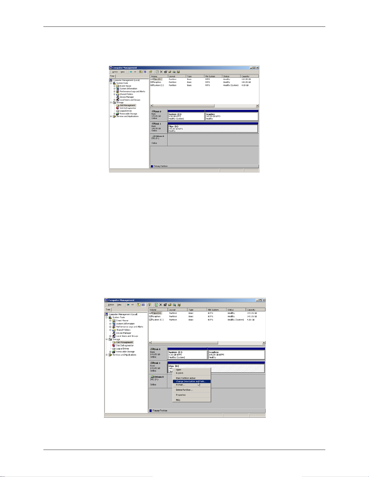
Chapter 5: System Maintenance
In the left pane (see Figure 5-32) click the “Disk Management.” A screen similar to that
shown in Figure 5-33 will be displayed. If necessary, expand the window’s size.
Figure 5-33: Computer Management window with Disk Management selected.
If the drive letter designations are as follows, go to Step 5:
-- Drive Disk 0 System equals (C:)
-- Drive Disk 0 Graphics equals (D:)
-- Drive Disk 1 Clips equals (E:)
-- Drive DVD/CD-ROM 0 equals (F:)
If the designation letters do not match what is listed above, an example of the procedure for
changing drive letters is as follows:
Right click on the drive word Clips (D:) and select “Change Drive Letters and Paths...” from
the pop-up window. Refer to Figure 5-34.
Figure 5-34: Change Drive Letters and Paths being selected
DekoCast Technical Reference And Service Guide
75
Page 76

Chapter 5: System Maintenance
Select “Edit...” from the “Change Drive Letters and Paths... window.” Refer to
Figure 5-35.
Figure 5-35: Change Drive Letters and Paths window
From the pull down select “H” as the new drive designation to be assigned to Clips and then
click “Ok.” Refer to Figure 5-36.
Figure 5-36: H designation selected for Clips Drive
Select “Yes” to confirm that the drive designation is to be assigned. Refer to Figure 5-37.
Figure 5-37: Confirmation of drive designation
Right click on the partition word Graphics (E:) and select “Change Drive Letters and
Paths...” from the pop-up window. Refer to Figure 5-38.
76
Figure 5-38: Change Drive Letters and Paths being selected
DekoCast Technical Reference And Service Guide
Page 77

Chapter 5: System Maintenance
Select “Change...” from the “Change Drive Letters and Paths... window.” Refer to
Figure 5-39.
Figure 5-39: Change Drive Letters and Paths window
From the pull down select “D” as the new drive designation to be assigned to Graphics and
then click “Ok.” Refer to Figure 5-40.
Figure 5-40: D designation selected for Graphics
Select “Yes” to confirm that the drive designation is to be assigned. Refer to Figure 5-41.
Figure 5-41: Confirmation of drive designation
Right click on the partition word Clips (H:) and select “Change Drive Letters and Paths...”
from the pop-up window. Refer to Figure 5-42.
Figure 5-42: Change Drive Letters and Paths being selected
DekoCast Technical Reference And Service Guide
77
Page 78

Chapter 5: System Maintenance
Select “Edit...” from the “Change Drive Letters and Paths... window.” Refer to
Figure 5-43.
Figure 5-43: Change Drive Letters and Paths window
From the pull down select “E” as the new drive designation to be assigned to Clips and then
click “Ok.” Refer to Figure 5-44.
Figure 5-44: E designation selected for Clips Drive
Select “Yes” to confirm that the drive designation is to be assigned. Refer to Figure 5-45.
Figure 5-45: Confirmation of drive designation
Repeat the process for any remaining partitions that need to be changed. Make sure the
partition designations are the same as those shown in Figure 5-46 below.
Important: When completed, your designations should match those shown in Figure 5-46.
Figure 5-46: The correct drive designations for a DekoCast workstation
Important: Disk 0 and Disk 1 should show as “Basic” and not “Dynamic.” Refer to Figure 5-46. If
one or the other shows as “Dynamic,” then right click the disk icon and choose “Convert To Basic.”
78
DekoCast Technical Reference And Service Guide
Page 79

Chapter 5: System Maintenance
4. Configuration for DekoCast OS is Complete.
Close the Computer Management window. The last part of the process is to install the
DekoCast program software. Refer to the “Installing The DekoCast Software” section
below.
Installing The DekoCast Software
The steps for installing the DekoCast program software are as follows:
1. Exit all Windows programs and reboot the DekoCast.
2. Insert the DekoCast Software CD into DVD/CD-ROM drive, and then click “Next” on
the W elcome s creen.
The CD will automatically run and start the installation when the software CD is inserted
into the DVD/CD-ROM drive.
Note: If the installation does not automatically run, you can use My Computer or Explorer to navigate to the
CD. In the CD's root directory, double-click on the file SETUP.EXE.
3. Accept the license agreement.
Click to check the “Yes, I accept” radio button.
4. Proceed with the software installation process.
The installation screens that are displayed are for the most part self-explanatory. In most
instances, use the default. The process is as follows:
-- The DekoCast Installer will remove some older “CODI” drivers if the older drivers are
3.5.1 or earlier. This may take several minutes. Select “Yes, I want to reboot my
computer now” and then click the “Finish” button when you are prompted to do so.
Your DekoCast system will then reboot.
Important: After the DekoCast system reboots, you may see some “Found New Hardware
Wizard” dialog boxes. Be sure to cancel out of each of these dialog boxes. The DekoCast
Installer will automatically resume.
-- The installer will then install the new “CODI” drivers. This may take several minutes.
-- The installer will then install PostDeko Lite and the DekoCast Application software.
Accept all of the defaults as presented. Then select “Yes, I want to reboot my
computer now” and click the “Finish” button when you are prompted to do so. Your
DekoCast system will then reboot. The installation process is complete at this point.
Important: If you have any problems with the installation process or the new version of software
contact Pinnacle Customer Support. Refer to Appendix A for contact information.
DekoCast Technical Reference And Service Guide
79
Page 80

Chapter 5: System Maintenance
Installing The Daria Bypass Card Software
On some DekoCast workstations it may become necessary to install the Daria Bypass Card
software. An easy check to see if the software is installed on a workstation is to navigate the
following path within Windows: St art menu >> Programs >> Pinnacle Systems >> Daria Pass through.
If “Daria Pass through” is not shown, then the Daria Bypass Card software needs to be installed
on the system.
The steps for installing the Daria Bypass Card utility software are as follows:
1. On the application CD, browse to the F:\Resources\DariaPassthrough\Driver folder and run the
setup.exe file.
2. Accept all the default selections. At the end ensure that “No, I want to reboot my computer
later” is checked and click the “Finish” button when you are prompted to do so.
3. On the application CD, browse to the F:\Resources\DariaPassthrough\Tester folder and run the
setup.exe file.
4. Accept all the default selections. At the end ensure that “Yes, I want to reboot my computer
now” is checked and click the “Finish” button when you are prompted to do so.
80
DekoCast Technical Reference And Service Guide
Page 81

Chapter 5: System Maintenance
Recreating A DekoCast Drive Image Restore DVD
Note: The Drive Image Restore DVD created in this process will only restore the operating system and supporting
utilities for the DekoCast. The actual DekoCast program is installed from the Deko Software CD.
Pinnacle Systems has provided a way that you can create a DekoCast “Drive Image Restore
DVD” in case the one originally sent with a DekoCast workstation can’t be found. To do this, you
will need a blank DVD of one of the following formats:
• DVD +R
• DVD +RW
Important: The DVD/CD-ROM drive on the DekoCast workstation will not properly burn a DVD that
has a format of -R or -RW.
Perform the following steps to recreate a Deko 300 Drive Image Restore DVD:
1. Power up the workstation and insert a blank DVD into the DVD/CD-ROM drive.
If necessary, close the Drive F window if it is displayed since nothing is on the DVD at this
time.
2. Start the software program named “Instant CD+DVD” on the workstation.
Navigate the following path to the Instant CD+DVD software program:
Start >> Programs >>Instant CD+DVD
Then click the program file “Instant CD+DVD” to open it. A window similar to that shown
in Figure 5-47 should be displayed.
Figure 5-47: Initial start up window of Instant CD+DVD
3. Click “Data Disk.” Refer to Figure 5-47.
Once Data Disk is clicked a New project window will be displayed similar to that shown in
Figure 5-48 with a New Project window displayed.
DekoCast Technical Reference And Service Guide
81
Page 82

Chapter 5: System Maintenance
Figure 5-48: New Project Dialog
4. Click “Cancel” for the New Project dialog.
Click the “Cancel” button. Refer to Figure 5-48.
5. Click the “New Project” menu icon.
A “New Disc Project” window similar to that shown in Figure 5-49 will be displayed.
Figure 5-49: New Disc Project window
6. Click the “Advanced Projects” box.
Click to check mark the “Advanced Projects” box. Refer to Figure 5-49.
7. Select “Raw / ISO Data.”
Click to highlight “Raw/ISO data” and then click “Next.” Refer to Figure 5-50.
82
DekoCast Technical Reference And Service Guide
Page 83

Chapter 5: System Maintenance
Figure 5-50: Raw/ISO Data selected
8. Browse to the Track1.iso file on Drive E (Clips drive) within the System Restore folder.
Once you have browsed to the Track1.iso file click “Next.” Refer to Figure 5-51.
Figure 5-51: Browsing to Track1.iso file
9. Select “Close This Wizard” and click “Finished.”
Refer to Figure 5-52.
Figure 5-52: Close This Wizard selected
DekoCast Technical Reference And Service Guide
83
Page 84

Chapter 5: System Maintenance
10. Click to highlight the word “Raw,” and then click “Properties” in the icon menu.
Raw is a file name under “Disc Projects” in the Projects Pane. Refer to Figure 5-53.
Figure 5-53: Clicking Raw file within Disc Projects subdirectory
Once the “Properties” menu icon is clicked, a window showing of the “Properties Of
Raw” will be displayed. Refer to Figure 5-54.
Figure 5-54: Properties Of Raw window displayed
11. From the pull down for “Disk Type” select “DVD.”
Select DVD as the Disc Type that is in the DVD/CD-ROM drive, and then click “Ok.”
Refer to Figure 5-54.
12. Click “Write” in the icon menu.
Refer to Figure 5-55. “Write” in the icon menu is represented by a red ball.
84
DekoCast Technical Reference And Service Guide
Page 85

Chapter 5: System Maintenance
Figure 5-55: Clicking Write in the icon menus
When “Write” in the icon menu is clicked a “write Disc Project” window will be
displayed. Refer to Figure 5-56. The drive image of the DekoCast operating system is
now ready to be copied to the DVD.
Figure 5-56: Write Disc Project window displayed
13. Click the “Write” button in the “Write Disk Project” dialog.
Click the “Write” button to begin writing the DekoCast operating system to the DVD.
Refer to Figure 5-56.
Once the “Write” button is click, a window indicating the progress of the data being
written onto the DVD will be displayed. Refer to Figure 5-57.
DekoCast Technical Reference And Service Guide
85
Page 86
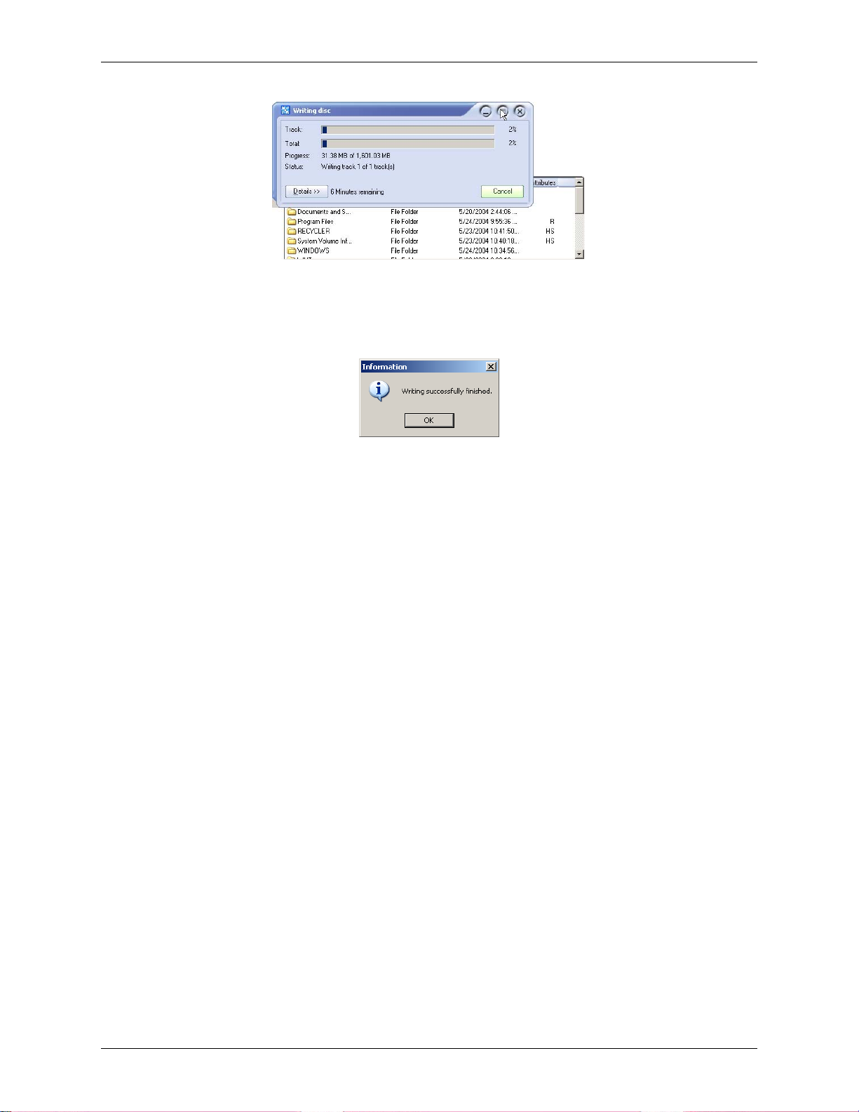
Chapter 5: System Maintenance
Figure 5-57: Progress indication of data being written to DVD
14. When “Writing Successfully Finished” (Figure 5-58) is displayed, the DVD can be
removed.
Figure 5-58: Successful creation of DekoCast Drive Image Restore DVD
15. Quit the Instant CD+DVD software program.
The DekoCast “Drive Image Restore DVD” you just created can now be used to restore
the DekoCast operating system. Refer to the section “You Have The Software DVDs
Supplied By Pinnacle Systems” above for instructions on restoring the DekoCast
operating system and restoring the Deko software program.
86
DekoCast Technical Reference And Service Guide
Page 87

Chapter 5: System Maintenance
Configuring A New “System” Hard Drive
If for whatever reason your “System” hard drive needed to be replaced, and you have receive a
new “System” hard drive from Pinnacle Systems Customer Support, the new “System” hard drive
will need to be configured. Perform the following steps to configure a new “System” hard drive
received from Pinnacle:
Important: Remove the “Media” hard drive before proceeding with this procedure to keep
from inadvertently over writing the content of the drive.
1. Insert the new replacement “System” hard drive into the workstation.
Refer to the “DekoCast Workstation Initial Setup” section in “Chapter 3: Installation And
Setup.”
2. Enter the BIOS setup of the workstation.
If the workstation has been turned off, power it up. Enter the BIOS program by rebooting
the workstation, and then at the beginning of the start-up procedure press and momentarily
hold down the <F2> key on the keyboard. This is done when you see the words “Press
<F2> for Setup” on the monitor, or when you see the three keyboard “Lock” LEDs (top
right-hand corner of the keyboard) flash on the keyboard.
3. Insert the “Drive Image Restore DVD” into the DVD/CD-ROM drive.
4. From within the BIOS display, check that the boot order for the drives is as follows:
Boot Menu
Silent Boot [Disabled]
Intel(R) Rapid BIOS Boot [Enabled]
PXE Boot to LAN [Disabled]
USB Boot [Disabled]
Boot Device Priority
1st Boot Device [1st Floppy Drive]
2nd Boot Device [3M-TEAC DV-W58G]
3rd Boot Device [PM-ST380013AS]
Hard Disk Drives Submenu
1st Drive [PM-ST380013AS]
2nd Boot Device [SM-ST3160023AS]
Important: The Hard Disk Drives Submenu must be in the order specified above. If not, your
Media (i.e., Clip) drive will be overwritten and not the System drive.
Use the arrow keys to get to the Boot menu. If it is necessary to correct the order of the
drives, change the order of the drives per the instructions given on the screen. When you’re
done, be sure to Save and Exit the BIOS program.
DekoCast Technical Reference And Service Guide
87
Page 88

Chapter 5: System Maintenance
5. Reboot the workstation (it may automatically reboot coming out of the BIOS).
You will see a prompt “Restoring will overwrite your system partition. Are you sure?
Select “Yes.” The Drive Image Restore program will take approximately 6 minutes to
complete. After the program has finished, the root directory for Drive A (shown as A:\>)
will be displayed.
6. Remove the “Drive Image Restore DVD” from the DVD drive and reboot the worksta-
tion.
A welcome screen will appear after the reboot.
7. A prompt will be displayed stating “The Product ID You Entered Is Not Valid.”
Click “OK” until the prompt is no longer displayed.
8. Enter the 25 characters that make up the product key number for the workstation.
The alpha-numeric characters that make the product key can be found on the front panel of
the workstation. If the DekoCast front panel cover is on the front of the workstation,
remove the panel cover. The product key sticker is glued onto the front panel of the
workstation. Type the product key onto the boxes displayed on the screen, then click
“Next.” A screen prompting for the name of the computer should appear.
9. Enter a name for the computer and click “Next.”
Only the characters A-Z, the numbers 0-9, and hyphens can be used. If the workstation is
connected to a network, then name given to the machine (and the description if one is given)
will appear on the network. When “Ok” is clicked, the Administrator password screen will
appear.
10.Select the Network Settings for the workstation.
The choices are “Typical Settings” and Custom Settings.” For most situations, the “Typical
Settings” selection will fulfill most needs. Contact your System Administration if you’re
not sure which to choose for the workstation.
11. Do not enter an Administrator password. Click “Next.”
A screen asking for the name of the workstation users will appear.
12. Select the “Workstation Computer Domain” for the workstation and click “Next.”
Contact your System Administration if you’re not sure if the workstation is to be part of a
domain. After “Next” is clicked, the software will load and the system will reboot.
13. Click “Next” on the initial screen of the Network Identification Wizard program.
The “Network Identification Wizard” program automatically launches after the system
reboots. After next is clicked a “Users Of This Computer” screen will appear .
14. Click “Next” on the “Users Of This Computer” screen.
Use the default settings. Do not type in a password for the password field.
88
DekoCast Technical Reference And Service Guide
Page 89

Chapter 5: System Maintenance
15. Click “Finish” to complete the software restore.
The DekoCast background screen will appear.
16. For now, click “Cancel” to each “Found New Hardware Wizards” pop-up window.
The pop ups will occur a number of times for the workstation.
17. If necessary, change the desktop to a resolution of 1024x768 with 32-bit color.
This is done by navigating the following path: Right click on desktop >> Properties
>>Settings tab Clicking the Settings tab will then show a window similar to that shown in Figure
5-59.
Figure 5-59: Display Properties window
Use the slider to adjust the screen resolution and bit depth to 1024x768 with 32-bit color.
Then click “Ok” and then “Yes” to keep the new resolution and color depth.
18. Right clicking on “My Computer” and select “Manage.”
A window similar to that in Figure 5-60 will be displayed.
Figure 5-60: Computer Management Window
DekoCast Technical Reference And Service Guide
89
Page 90

Chapter 5: System Maintenance
19. Right click on the unallocated black area for Disk 0 and select “Create Partition.”
Refer to Figure 5-61.
Figure 5-61: Select “Create Partition” for Drive 1.
20. The “Create Partition Wizard” will appear. Click “Next.”
Refer to Figure 5-62.
Figure 5-62: Partition Wizard Window
21. Select “Primary” as the partition type and click “Next.”
Refer to Figure 5-63.
Figure 5-63: Select Primary as the type
90
DekoCast Technical Reference And Service Guide
Page 91

Chapter 5: System Maintenance
22. Use the maximum disk space for the partition size. Click “Next.”
Refer to Figure 5-64.
Figure 5-64: Maximum disk size selected
23. Assign “D” as the drive letter. Click “Next.”
Refer to Figure 5-65.
Figure 5-65: Drive letter designation
24. The “Volume label” name must be Graphics, and the box for “Perform a Quick Format” must be check marked.
Make sure you spell the word Graphics correctly . If any other name is used here, the drive
will not work. Refer to Figure 5-66. Click the “Perform a Quick Format” box to place a
check mark there. Click “Next” to continue.
Figure 5-66: Partition format designations
DekoCast Technical Reference And Service Guide
91
Page 92

Chapter 5: System Maintenance
25. Click “Finished.”
Refer to Figure 5-67.
The drive will format. When formatting is complete, the drive partitioning for the
workstation should look as shown in Figure 5-68.
Figure 5-67: Successful completion Of Create Partition Wizard
Figure 5-68: Successful formatting of drive
26. Place any material you previously backed up from your old “System” (Graphics D:)
hard drive to the new “System” (Graphics D:) hard drive.
92
DekoCast Technical Reference And Service Guide
Page 93

Chapter 5: System Maintenance
Configuring A New “Media” Hard Drive
If for whatever reason your “Media” hard drive needed to be replaced, and you have receive a
new “Media” hard drive from Pinnacle Systems Customer Support, the new “Media” hard drive
will need to be configured. Perform the following steps to configure a new “Media” hard drive
received from Pinnacle:
1. Insert the new replacement “Media” hard drive into the workstation.
Refer to the “DekoCast Workstation Initial Setup” section in “Chapter 3: Installation And
Setup.”
2. Enter the BIOS setup of the workstation.
If the workstation has been turned off, power it up. Enter the BIOS program by rebooting
the workstation, and then at the beginning of the start-up procedure press and momentarily
hold down the <F2> key on the keyboard. This is done when you see the words “Press
<F2> for Setup” on the monitor, or when you see the three keyboard “Lock” LEDs (top
right-hand corner of the keyboard) flash on the keyboard.
3. From within the BIOS display, check that the boot order for the drives is as follows:
Boot Menu
Silent Boot [Disabled]
Intel(R) Rapid BIOS Boot [Enabled]
PXE Boot to LAN [Disabled]
USB Boot [Disabled]
Boot Device Priority
1st Boot Device [1st Floppy Drive]
2nd Boot Device [3M-TEAC DV-W58G]
3rd Boot Device [PM-ST380013AS]
Hard Disk Drives Submenu
1st Drive [PM-ST380013AS]
2nd Boot Device [SM-ST3160023AS]
Use the arrow keys to get to the Boot menu. If it is necessary to correct the order of the
drives, change the order of the drives per the instructions given on the screen.
4. If you corrected the order of the drives, be sure to Save and Exit the BIOS program.
The Windows desktop should be displayed.
5. Right clicking on “My Computer” and select “Manage.”
A window similar to that in Figure 5-69 will be displayed.
DekoCast Technical Reference And Service Guide
93
Page 94

Chapter 5: System Maintenance
Figure 5-69: Computer Management Window
6. Right click on the unallocated black area for Disk 1 and select “Write Signature.”
Refer to Figure 5-70.
Figure 5-70: Select “Write Signature” for Drive 1.
7. Check that Disk 1 is check marked for a signature to be written.
Click the “Disk 1” box to place a check mark there. Click “Next” to continue.
Figure 5-71: Partition format designations
8. Right click on the unallocated black area for Disk 1 and select “Create Partition.”
Refer to Figure 5-72.
94
DekoCast Technical Reference And Service Guide
Page 95

Figure 5-72: Select “Create Partition” for Drive 1.
9. The “Create Partition Wizard” will appear. Click “Next.”
Refer to Figure 5-73.
Chapter 5: System Maintenance
Figure 5-73: Partition Wizard Window
10. Select “Primary” as the partition type and click “Next.”
Refer to Figure 5-74.
Figure 5-74: Select Primary as the type
DekoCast Technical Reference And Service Guide
95
Page 96

Chapter 5: System Maintenance
11. Use the maximum disk space for the partition size. Click “Next.”
Refer to Figure 5-75.
Figure 5-75: Maximum disk size selected
12. Assign “E” as the drive letter. Click “Next.”
Refer to Figure 5-76.
Figure 5-76: Drive letter designation
13. The “Volume label” name must be Clips, and the box for “Perform a Quick Format”
must be check marked.
Make sure you spell the word Clips correctly. If any other name is used here, the drive
will not work. Refer to Figure 5-77. Click the “Perform a Quick Format” box to place a
check mark there. Click “Next” to continue.
Figure 5-77: Partition format designations
96
DekoCast Technical Reference And Service Guide
Page 97

Chapter 5: System Maintenance
14. Click “Finished.”
Refer to Figure 5-78.
Figure 5-78: Successful completion Of Create Partition Wizard
The drive will format. When formatting is complete, the drive partitioning for the
workstation should look as shown in Figure 5-79.
Figure 5-79: Successful formatting of drive
15. Place any material you previously backed up fr om your old “Media” (Clips E:) hard
drive to the new “Media” (Clips E:) hard drive.
DekoCast Technical Reference And Service Guide
97
Page 98

Chapter 5: System Maintenance
98
DekoCast Technical Reference And Service Guide
Page 99

Appendix A: Pinnacle Systems Customer Support
About Deko Support
Additional resources are available online. FAQs, public web boards, and late-breaking
documentation are posted at the Pinnacle Systems web site for Deko products. Use the following
link address:
http://www.pinnaclesys.com/support
Answers to all of the problems you encounter may not be found here, but what is there can help
stimulate new thoughts and ideas about the source of the problem.
Troubleshooting Questionnaire
Before contacting Pinnacle Systems Customer Support, please complete the Troubleshooting
Questionnaire below and have the answers ready before you contact us.
1. What is the product model and software version number?
2. Can you reproduce the problem consistently or is the problem intermittent?
3. What version of the operating system are you using?
4. When did the problem start? Has the product ever worked? What was the last thing
changed or added to the system?
5. What is the exact wording of any error messages you have received?
6. Are you using the product as it was intended or recommended to be used?
7. Does the issue disappear if you boot the system with all third-party devices removed?
8. What have you done to try to resolve the issue yourself?
Once you know the answers to the questions listed above, you should contact Pinnacle Systems
Customer Support for additional help.
Contacting Pinnacle Systems
Request support from Pinnacle Systems via E-mail or the web. Please be sure to include your
name, phone number, and the serial number of the DekoCast workstation with your request. The
appropriate member of the Pinnacle Systems support team will respond to your request. Support
by region is as follows:
Important: Please keep this manual at a place where it can readily be found. When you are contacted by
Pinnacle Systems Customer Support, you made need this document for troublesho oting and maintenance
of your system while on the phone with the Support Engineer.
Broadcast Support Americas and Canada
E-mail: broadcast-support@pinnaclesys.com
Web Support: http://www.pinnaclesys.com/support/contact
DekoCast Technical Reference And Service Guide
99
Page 100

Appendix A: Pinnacle Systems Customer Support
Broadcast Support Europe
E-mail: broadcast-support-uk@pinnaclesys.com
Web Support: http://www.pinnaclesys.com/support/contact
Broadcast Support South Asia
E-mail: pacrim-support@pinnaclesys.com
Web Support: http://www.pinnaclesys.com/support/contact
Supports Regions: Taiwan, India, Pakistan, Bangladesh, Sri Lanka, Australia, New Zealand,
Thailand, Viet Nam, Philippines, Brunei, Singapore, Malaysia, Indonesia
Broadcast Support Beijing
E-mail: broadcast-support-cn@pinnaclesys.com
Web Support: http://www.pinnaclesys.com/support/contact
Supports Regions: China, Hong Kong, Korea
Broadcast Support Japan
E-mail broadcast@pinnaclesys.co.jp
Web Support: www.pinnaclesys.co.jp
Upgrade Information on the Internet
For the latest information on Pinnacle Systems products, visit the Pinnacle Systems web site at:
http://www.pinnaclesys.com/support
100
DekoCast Technical Reference And Service Guide
 Loading...