

Page 1

Avid® Color Correction
User’s Guide
make manage move | media
™
Avid
®
Page 2

Copyright and Disclaimer
Product specifications are subject to change without notice and do not represent a commitment on the part
of Avid Technology, Inc.
The software described in this document is furnished under a license agreement. You can obtain a copy of
that license by visiting Avid's Web site at www.avid.com. The terms of that license are also available in the
product in the same directory as the software. The software may not be reverse assembled and may be
used or copied only in accordance with the terms of the license agreement. It is against the law to copy the
software on any medium except as specifically allowed in the license agreement. Avid products or portions
thereof are protected by one or more of the following United States patents: 4,746,994; 4,970,663;
5,045,940; 5,267,351; 5,309,528; 5,355,450; 5,396,594; 5,440,348; 5,452,378; 5,467,288; 5,513,375;
5,528,310; 5,557,423; 5,568,275; 5,577,190; 5,583,496; 5,584,006; 5,627,765; 5,640,601; 5,644,364;
5,654,737; 5,715,018; 5,719,570; 5,724,605; 5,726,717; 5,729,673; 5,745,637; 5,752,029; 5,754,851;
5,799,150; 5,812,216; 5,828,678; 5,842,014; 5,852,435; 5,905,841; 5,929,836; 5,930,445; 5,946,445;
5,987,501; 5,999,406; 6,016,152; 6,018,337; 6,023,531; 6,038,573; 6,058,236; 6,061,758; 6,091,778;
6,105,083; 6,118,444; 6,128,001; 6,134,607; 6,137,919; 6,141,007; 6,141,691; 6,198,477; 6,201,531;
6,211,869; 6,223,211; 6,249,280; 6,269,195; 6,317,158; 6,317,515; 6,330,369; 6,351,557; 6,353,862;
6,357,047; 6,392,710; 6,404,435; 6,407,775; 6,417,891; 6,426,778; 6,477,271; 6,489,969; 6,512,522;
6,532,043; 6,546,190; 6,552,731; 6,553,142; 6,570,624; 6,571,255; 6,583,824; 6,596,031; 6,618,547;
6,636,869; 6,665,450; 6,678,461; 6,687,407; D352,278; D372,478; D373,778; D392,267; D392,268;
D392,269; D395,291; D396,853; D398,912. Other patents are pending.
No part of this document may be reproduced or transmitted in any form or by any means, electronic or
mechanical, including photocopying and recording, for any purpose without the express written permission
of Avid Technology, Inc.
Copyright © 2004 Avid Technology, Inc. and its licensors. All rights reserved. Printed in USA.
The following disclaimer is required by Apple Computer, Inc.
APPLE COMPUTER, INC. MAKES NO WARRANTIES WHATSOEVER, EITHER EXPRESS OR IMPLIED,
REGARDING THIS PRODUCT, INCLUDING WARRANTIES WITH RESPECT TO ITS
MERCHANTABILITY OR ITS FITNESS FOR ANY PARTICULAR PURPOSE. THE EXCLUSION OF
IMPLIED WARRANTIES IS NOT PERMITTED BY SOME STATES. THE ABOVE EXCLUSION MAY NOT
APPLY TO YOU. THIS WARRANTY PROVIDES YOU WITH SPECIFIC LEGAL RIGHTS. THERE MAY BE
OTHER RIGHTS THAT YOU MAY HAVE WHICH VARY FROM STATE TO STATE.
The following disclaimer is required by Sam Leffler and Silicon Graphics, Inc. for the use of
their TIFF library:
Copyright © 1988–1997 Sam Leffler
Copyright © 1991–1997 Silicon Graphics, Inc.
Permission to use, copy, modify, distribute, and sell this software [i.e., the TIFF library] and its
documentation for any purpose is hereby granted without fee, provided that (i) the above copyright notices
and this permission notice appear in all copies of the software and related documentation, and (ii) the
names of Sam Leffler and Silicon Graphics may not be used in any advertising or publicity relating to the
software without the specific, prior written permission of Sam Leffler and Silicon Graphics.
THE SOFTWARE IS PROVIDED “AS-IS” AND WITHOUT WARRANTY OF ANY KIND, EXPRESS,
IMPLIED OR OTHERWISE, INCLUDING WITHOUT LIMITATION, ANY WARRANTY OF
MERCHANTABILITY OR FITNESS FOR A PARTICULAR PURPOSE.
IN NO EVENT SHALL SAM LEFFLER OR SILICON GRAPHICS BE LIABLE FOR ANY SPECIAL,
INCIDENTAL, INDIRECT OR CONSEQUENTIAL DAMAGES OF ANY KIND, OR ANY DAMAGES
WHATSOEVER RESULTING FROM LOSS OF USE, DATA OR PROFITS, WHETHER OR NOT ADVISED
OF THE POSSIBILITY OF DAMAGE, AND ON ANY THEORY OF LIABILITY, ARISING OUT OF OR IN
CONNECTION WITH THE USE OR PERFORMANCE OF THIS SOFTWARE.
The following disclaimer is required by the Independent JPEG Group:
Portions of this software are based on work of the Independent JPEG Group.
The following disclaimer is required by Paradigm Matrix:
Portions of this software licensed from Paradigm Matrix.
2
Page 3

The following disclaimer is required by Ray Sauers Associates, Inc.:
“Install-It” is licensed from Ray Sauers Associates, Inc. End-User is prohibited from taking any action to
derive a source code equivalent of “Install-It,” including by reverse assembly or reverse compilation, Ray
Sauers Associates, Inc. shall in no event be liable for any damages resulting from reseller’s failure to
perform reseller’s obligation; or any damages arising from use or operation of reseller’s products or the
software; or any other damages, including but not limited to, incidental, direct, indirect, special or
consequential Damages including lost profits, or damages resulting from loss of use or inability to use
reseller’s products or the software for any reason including copyright or patent infringement, or lost data,
even if Ray Sauers Associates has been advised, knew or should have known of the possibility of such
damages.
The following disclaimer is required by Videomedia, Inc.:
“Videomedia, Inc. makes no warranties whatsoever, either express or implied, regarding this product,
including warranties with respect to its merchantability or its fitness for any particular purpose.”
“This software contains V-LAN ver. 3.0 Command Protocols which communicate with V-LAN ver. 3.0
products developed by Videomedia, Inc. and V-LAN ver. 3.0 compatible products developed by third parties
under license from Videomedia, Inc. Use of this software will allow “frame accurate” editing control of
applicable videotape recorder decks, videodisc recorders/players and the like.”
The following disclaimer is required by Altura Software, Inc. for the use of its Mac2Win
software and Sample Source Code:
©1993–1998 Altura Software, Inc.
The following disclaimer is required by Ultimatte Corporation:
Certain real-time compositing capabilities are provided under a license of such technology from Ultimatte
Corporation and are subject to copyright protection.
The following disclaimer is required by 3Prong.com Inc.:
Certain waveform and vector monitoring capabilities are provided under a license from 3Prong.com Inc.
Attn. Government User(s). Restricted Rights Legend
U.S. GOVERNMENT RESTRICTED RIGHTS. This Software and its documentation are “commercial
computer software” or “commercial computer software documentation.” In the event that such Software or
documentation is acquired by or on behalf of a unit or agency of the U.S. Government, all rights with
respect to this Software and documentation are subject to the terms of the License Agreement, pursuant to
FAR §12.212(a) and/or DFARS §227.7202-1(a), as applicable.
Trademarks
888 I/O, Adrenaline, AirPlay, AirSPACE, AirSPACE HD, AniMatte, AudioSuite, AudioVision, AutoSync, Avid,
Avid DNA, AVIDdrive, AVIDdrive Towers, Avid Mojo, AvidNet, AvidNetwork, AVIDstripe, Avid Unity,
Avid Xpress, AVoption, AVX, CamCutter, ChromaCurve, ChromaWheel, DAE, D-Fi, D-fx, Digidesign,
Digidesign Audio Engine, Digidesign Intelligent Noise Reduction, DigiDrive, Digital Nonlinear Accelerator,
DigiTranslator, DINR, D-Verb, Equinox, ExpertRender, FieldPak, Film Composer, FilmScribe, FluidMotion,
HIIP, HyperSPACE, HyperSPACE HDCAM, IllusionFX, Image Independence, Intraframe, iS9, iS18, iS23,
iS36, Lo-Fi, Magic Mask, make manage move | media, Marquee, Matador, Maxim, MCXpress,
Media Composer, MediaDock, MediaDock Shuttle, Media Fusion, Media Illusion, MediaLog,
Media Reader, Media Recorder, MEDIArray, MediaShare, Meridien, MetaSync, NaturalMatch, Nearchive,
NetReview, NewsCutter, Nitris, OMF, OMF Interchange, OMM, Open Media Framework,
Open Media Management, ProEncode, Pro Tools, QuietDrive, Recti-Fi, RetroLoop, rS9, rS18, Sci-Fi,
Softimage, Sound Designer II, SPACE, SPACEShift, Symphony, the Avid|DS logo, Trilligent, UnityRAID,
Vari-Fi, Video Slave Driver, VideoSPACE, and Xdeck are either registered trademarks or trademarks of
Avid Technology, Inc. in the United States and/or other countries.
iNEWS, iNEWS ControlAir, and Media Browse are trademarks of iNews, LLC.
Adobe and Photoshop are either registered trademarks or trademarks of Adobe Systems Incorporated in
the United States and/or other countries. Apple, Macintosh, and Mac OS are trademarks of Apple
Computer, Inc., registered in the U.S. and other countries. Windows is either a registered trademark or
trademark of Microsoft Corporation in the United States and/or other countries. All other trademarks
contained herein are the property of their respective owners.
All other trademarks contained herein are the property of their respective owners.
3
Page 4

Footage
Arri — Courtesy of Arri/Fauer — John Fauer, Inc.
Bell South “Anticipation” — Courtesy of Two Headed Monster — Tucker/Wayne Atlanta/GMS.
Canyonlands — Courtesy of the National Park Service/Department of the Interior.
Eco Challenge British Columbia — Courtesy of Eco Challenge Lifestyles, Inc., All Rights Reserved.
Eco Challenge Morocco — Courtesy of Discovery Communications, Inc.
It’s Shuttletime — Courtesy of BCP & Canadian Airlines.
Nestlé Coffee Crisp — Courtesy of MacLaren McCann Canada.
Saturn “Calvin Egg” — Courtesy of Cossette Communications.
“Tigers: Tracking a Legend” — Courtesy of www.wildlifeworlds.com, Carol Amore, Executive Producer.
Windhorse — Courtesy of Paul Wagner Productions.
GOT FOOTAGE?
Editors — Filmmakers — Special Effects Artists — Game Developers — Animators — Educators —
Broadcasters — Content creators of every genre — Just finished an incredible project and want to
share it with the world?
Send us your reels and we may use your footage in our show reel or demo!*
For a copy of our release and Avid’s mailing address, go to www.avid.com/footage.
*Note: Avid cannot guarantee the use of materials submitted.
Avid Color Correction User’s Guide • 0130-06113-01 • June 2004
4
Page 5

Contents
Using This Guide. . . . . . . . . . . . . . . . . . . . . . . . . . . . . . . . . . . . . . . 11
About This Guide . . . . . . . . . . . . . . . . . . . . . . . . . . . . . . . . . . . . . . . . . . . . . 12
Symbols and Conventions . . . . . . . . . . . . . . . . . . . . . . . . . . . . . . . . . . . . . . 13
If You Need Help. . . . . . . . . . . . . . . . . . . . . . . . . . . . . . . . . . . . . . . . . . . . . . 14
If You Have Documentation Comments . . . . . . . . . . . . . . . . . . . . . . . . . . . . 14
How to Order Documentation . . . . . . . . . . . . . . . . . . . . . . . . . . . . . . . . . . . . 15
Avid Educational Services. . . . . . . . . . . . . . . . . . . . . . . . . . . . . . . . . . . . . . . 15
Chapter 1 Introducing Avid Color Correction . . . . . . . . . . . . . . . . . . . . . . . . 17
Understanding Avid Color Correction . . . . . . . . . . . . . . . . . . . . . . . . . . . . . . 17
Applying and Viewing Color Corrections . . . . . . . . . . . . . . . . . . . . . . . . 18
Automatic and Manual Color Corrections. . . . . . . . . . . . . . . . . . . . . . . . 18
The Color Correction Effect . . . . . . . . . . . . . . . . . . . . . . . . . . . . . . . . . . 19
Understanding Color Correction Groups . . . . . . . . . . . . . . . . . . . . . . . . 19
Other Color Adjustment Tools. . . . . . . . . . . . . . . . . . . . . . . . . . . . . . . . . . . . 20
Chapter 2 Understanding Color Correction Mode . . . . . . . . . . . . . . . . . . . . . 21
Entering and Exiting Color Correction Mode. . . . . . . . . . . . . . . . . . . . . . . . . 21
Overview of the Color Correction Mode Toolset . . . . . . . . . . . . . . . . . . . . . . 23
The Composer Window in Color Correction Mode . . . . . . . . . . . . . . . . . . . . 23
Activating Monitors . . . . . . . . . . . . . . . . . . . . . . . . . . . . . . . . . . . . . . . . . 24
Displaying Tracking Information . . . . . . . . . . . . . . . . . . . . . . . . . . . . . . . 25
Displaying Images in Monitors . . . . . . . . . . . . . . . . . . . . . . . . . . . . . . . . 25
Understanding Default Monitor Display. . . . . . . . . . . . . . . . . . . . . . 25
Configuring Image Display in Monitors . . . . . . . . . . . . . . . . . . . . . . 26
Splitting the Image Display in Monitors . . . . . . . . . . . . . . . . . . . . . . 28
5
Page 6

Hiding the Video in Monitors. . . . . . . . . . . . . . . . . . . . . . . . . . . . . . 30
Displaying 16:9 Video in Monitors . . . . . . . . . . . . . . . . . . . . . . . . . 30
Using the Composer Window Buttons. . . . . . . . . . . . . . . . . . . . . . . . . . 31
Using the Play Loop Button in Color Correction Mode . . . . . . . . . . . . . 32
The Client Monitor in Color Correction Mode. . . . . . . . . . . . . . . . . . . . . . . . 33
The Color Correction Tool . . . . . . . . . . . . . . . . . . . . . . . . . . . . . . . . . . . . . . 34
Working with the Group and Subdividing Tabs . . . . . . . . . . . . . . . . . . . 34
Displaying a Group Tab . . . . . . . . . . . . . . . . . . . . . . . . . . . . . . . . . 35
Displaying an HSL Subdividing Tab . . . . . . . . . . . . . . . . . . . . . . . . 35
Understanding Interaction Between Color Correction Groups . . . . . . . 36
Working with the Enable Buttons. . . . . . . . . . . . . . . . . . . . . . . . . . . . . . 37
Turning Controls On or Off . . . . . . . . . . . . . . . . . . . . . . . . . . . . . . . 37
Resetting Controls . . . . . . . . . . . . . . . . . . . . . . . . . . . . . . . . . . . . . 38
Understanding Interaction Between Enable Buttons . . . . . . . . . . . 38
Using the Color Correction Tool Buttons. . . . . . . . . . . . . . . . . . . . . . . . 39
Customizing Color Correction Mode Settings . . . . . . . . . . . . . . . . . . . . 40
Adding Comments to Color Correction Effects . . . . . . . . . . . . . . . . . . . 41
Working with Color Correction Effect Templates . . . . . . . . . . . . . . . . . . . . . 43
Understanding How Color Correction Effect Templates Save Settings. 44
Saving a Color Correction Effect Template to a Bin . . . . . . . . . . . . . . . 44
Saving a Color Correction Effect Template to a Bucket . . . . . . . . . . . . 45
Applying Color Correction Effect Templates . . . . . . . . . . . . . . . . . . . . . 46
Working with Color Correction Effect Templates in the Effect Palette. . 48
Chapter 3 Performing Color Corrections . . . . . . . . . . . . . . . . . . . . . . . . . . . . 51
General Workflow for Making Color Corrections . . . . . . . . . . . . . . . . . . . . . 51
Using Automatic Color Corrections . . . . . . . . . . . . . . . . . . . . . . . . . . . . . . . 53
Understanding Automatic Color Correction. . . . . . . . . . . . . . . . . . . . . . 53
Adjusting Contrast and Balance Automatically . . . . . . . . . . . . . . . . . . . 54
Using the Remove Color Cast Buttons . . . . . . . . . . . . . . . . . . . . . . . . . 56
Considerations When Using Automatic Color Correction . . . . . . . . . . . 58
6
Page 7

Using the Color Match Control . . . . . . . . . . . . . . . . . . . . . . . . . . . . . . . . . . . 59
Making a Correction with the Color Match Control. . . . . . . . . . . . . . . . . 60
Selecting Match Type Options . . . . . . . . . . . . . . . . . . . . . . . . . . . . . . . . 62
Understanding NaturalMatch . . . . . . . . . . . . . . . . . . . . . . . . . . . . . . . . . 64
Color Match Example Using NaturalMatch . . . . . . . . . . . . . . . . . . . . . . 64
Saving Custom Colors to a Bin . . . . . . . . . . . . . . . . . . . . . . . . . . . . . . . 66
Getting RGB Information Using the Color Match Control. . . . . . . . . . . . 67
The HSL (Hue, Saturation, Luminance) Group . . . . . . . . . . . . . . . . . . . . . . . 67
Working with the Controls Tab . . . . . . . . . . . . . . . . . . . . . . . . . . . . . . . . 68
Making Corrections Using the Controls Tab . . . . . . . . . . . . . . . . . . 68
Using the HSL Sliders . . . . . . . . . . . . . . . . . . . . . . . . . . . . . . . . . . . 69
Controls Tab Controls . . . . . . . . . . . . . . . . . . . . . . . . . . . . . . . . . . . 70
Working with the Hue Offsets Tab . . . . . . . . . . . . . . . . . . . . . . . . . . . . . 71
Understanding the ChromaWheel Controls. . . . . . . . . . . . . . . . . . . 72
Making Corrections Using the Hue Offsets Tab . . . . . . . . . . . . . . . 74
Using the ChromaWheel Crosshair Pointers. . . . . . . . . . . . . . . . . . 75
The Curves Group. . . . . . . . . . . . . . . . . . . . . . . . . . . . . . . . . . . . . . . . . . . . . 76
Understanding ChromaCurve Graphs . . . . . . . . . . . . . . . . . . . . . . . . . . 77
Making Corrections Using the Curves Tab. . . . . . . . . . . . . . . . . . . . . . . 79
Adjusting ChromaCurve Graphs . . . . . . . . . . . . . . . . . . . . . . . . . . . . . . 79
ChromaCurve Graphs and the Color Match Control . . . . . . . . . . . . . . . 82
Examples of ChromaCurve Graph Adjustments . . . . . . . . . . . . . . . . . . 84
Working with the Waveform Monitors and Vectorscope Monitor. . . . . . . . . . 91
Displaying a Waveform Monitor or Vectorscope Monitor . . . . . . . . . . . . 91
Using the Waveform and Vectorscope Information . . . . . . . . . . . . . . . . 99
Applying Color Corrections to an Entire Sequence. . . . . . . . . . . . . . . . . . . 101
7
Page 8

Using Color Correction Effects in the Effect Palette. . . . . . . . . . . . . . . . . . 102
Performing Automatic Color Corrections from the Effect Palette . . . . 102
Selecting AutoCorrect Options . . . . . . . . . . . . . . . . . . . . . . . . . . . 102
Applying Automatic Color Corrections from the Effect Palette . . . 104
Working with the Color Correction Effect. . . . . . . . . . . . . . . . . . . . . . . 106
Chapter 4 Color Correction Techniques . . . . . . . . . . . . . . . . . . . . . . . . . . . . 107
Guiding Principles for Color Correction . . . . . . . . . . . . . . . . . . . . . . . . . . . 107
Goals of Color Correction: Restoration and Adaptation . . . . . . . . . . . 108
Restoring the Original Look . . . . . . . . . . . . . . . . . . . . . . . . . . . . . 108
Adapting the Original Look . . . . . . . . . . . . . . . . . . . . . . . . . . . . . . 109
Stages of Color Correction . . . . . . . . . . . . . . . . . . . . . . . . . . . . . . . . . 109
Correcting Tonal Range . . . . . . . . . . . . . . . . . . . . . . . . . . . . . . . . 110
Neutralizing Color . . . . . . . . . . . . . . . . . . . . . . . . . . . . . . . . . . . . . 111
Achieving Shot-to-Shot Consistency . . . . . . . . . . . . . . . . . . . . . . 113
Achieving a Final Look . . . . . . . . . . . . . . . . . . . . . . . . . . . . . . . . . 113
Examples of Color Correction Problems . . . . . . . . . . . . . . . . . . . . . . . . . . 114
Example 1 . . . . . . . . . . . . . . . . . . . . . . . . . . . . . . . . . . . . . . . . . . . . . . 114
Example 2 . . . . . . . . . . . . . . . . . . . . . . . . . . . . . . . . . . . . . . . . . . . . . . 118
Chapter 5 Safe Colors. . . . . . . . . . . . . . . . . . . . . . . . . . . . . . . . . . . . . . . . . . . 123
Overview of Safe Color Limits . . . . . . . . . . . . . . . . . . . . . . . . . . . . . . . . . . 123
Setting Safe Color Limits . . . . . . . . . . . . . . . . . . . . . . . . . . . . . . . . . . . . . . 124
Understanding the Graphical View of Safe Color Settings. . . . . . . . . . . . . 126
Understanding Safe Color Warnings . . . . . . . . . . . . . . . . . . . . . . . . . . . . . 128
Safe Color Warnings in the Monitors. . . . . . . . . . . . . . . . . . . . . . . . . . 129
Safe Color Warnings in the Color Match Control. . . . . . . . . . . . . . . . . 131
Making Adjustments to Achieve Safe Color Values . . . . . . . . . . . . . . 131
Safe Color Limits with Waveform and Vectorscope Information . . . . . . . . 133
Index . . . . . . . . . . . . . . . . . . . . . . . . . . . . . . . . . . . . . . . . . . . . . . . . 137
8
Page 9

Tables
Source Menu Commands . . . . . . . . . . . . . . . . . . . . . . . . . . . . . . . . . . . . . . . 27
Composer Window Buttons. . . . . . . . . . . . . . . . . . . . . . . . . . . . . . . . . . . . . . 32
Correction Mode Settings Feature Tab Options . . . . . . . . . . . . . . . . . . . . . . 41
Automatic Contrast and Balance Buttons . . . . . . . . . . . . . . . . . . . . . . . . . . . 55
Match Type Options . . . . . . . . . . . . . . . . . . . . . . . . . . . . . . . . . . . . . . . . . . . 62
Controls Tab Controls . . . . . . . . . . . . . . . . . . . . . . . . . . . . . . . . . . . . . . . . . . 70
Hue Offsets Tab Controls . . . . . . . . . . . . . . . . . . . . . . . . . . . . . . . . . . . . . . . 75
Hue Offsets ChromaWheel Crosshair Pointers. . . . . . . . . . . . . . . . . . . . . . . 76
Waveform and Vectorscope Commands . . . . . . . . . . . . . . . . . . . . . . . . . . . 92
AutoCorrect Options . . . . . . . . . . . . . . . . . . . . . . . . . . . . . . . . . . . . . . . . . . 104
Safe Color Settings Options . . . . . . . . . . . . . . . . . . . . . . . . . . . . . . . . . . . . 125
Safe Color Warning Indicators . . . . . . . . . . . . . . . . . . . . . . . . . . . . . . . . . . 129
Safe Color Limits in Waveform Displays . . . . . . . . . . . . . . . . . . . . . . . . . . . 134
9
Page 10

10
Page 11

Using This Guide
This guide provides information on the color correction features of your Avid®
system. Using these features, you can easily make adjustments to color that
will improve the appearance of the video material in your projects.
If your project workflow normally includes traditional color correction,
your system’s color correction tools can reduce or even eliminate the need
for such procedures. If your workflow has not allowed for extensive color
correction in the past, your system’s color correction tools can make
possible a new level of color-finishing quality.
n
The documentation describes the features and hardware of all models.
Therefore, your system might not contain certain features and hardware that
are covered in the documentation.
This guide is intended for all Avid Color Correction users, from beginning
to advanced.
Unless noted otherwise, the material in this document applies to the
Windows XP and Mac OS X operating systems.The majority of screen shots
in this document were captured on a Windows XP system, but the information
applies to both Windows XP and Mac OS X systems. Where differences exist,
both Windows XP and Mac OS X screen shots are shown.
Page 12

Using This Guide
About This Guide
This guide is designed to provide you with all the information you need to
make precise color adjustments using your Avid system, including
complete explanations of all the color correction tools. The guide leads you
through all color correction procedures with task-oriented instructions.
Many examples of color correction techniques and typical color correction
problems help you understand what to look for when you are correcting
color in a sequence. Thorough cross-references to other parts of your Avid
documentation make it easy for you to find additional information.
n
If you are reading a black-and-white hardcopy printout of this document, you
will find it useful to view the color images in the Help or in the online version
of this document on the online publications CD-ROM.
The Contents lists all topics included in the book. They are presented with
the following overall structure:
• Chapter 1 provides a general introduction to Avid Color Correction and
summarizes all the other color adjustment tools.
• Chapter 2 describes the Color Correction mode display in detail and
explains how to control, customize, and move around in Color
Correction mode.
• Chapter 3 provides step-by-step instructions for all the color
adjustment operations you can perform using the Color Correction
tool, together with conceptual information and examples to help you
understand the differences between the various color correction
controls.
• Chapter 4 provides guidelines for approaching the task of color
correction, examples of typical color correction problems, and
discussions of how to solve those problems using your system’s color
correction tools. This chapter is especially useful as an introduction to
color correction for Avid users who have little prior experience making
color adjustments.
12
• Chapter 5 explains the Safe Color warning function of your Avid
system.
•The Index helps you quickly locate specific topics.
Page 13

Symbols and Conventions
Avid documentation uses the following symbols and conventions:
Symbol or Convention Meaning or Action
Symbols and Conventions
n
c
w
> This symbol indicates menu commands (and
t
k
Margin tips
(Windows), (Windows only),
(Macintosh), or (Macintosh
only)
A note provides important related information,
reminders, recommendations, and strong suggestions.
A caution means that a specific action you take could
cause harm to your computer or cause you to lose data.
A warning describes an action that could cause you
physical harm. Follow the guidelines in this document
or on the unit itself when handling electrical
equipment.
subcommands) in the order you select them. For
example, File > Import means to open the File menu
and then select the Import command.
This symbol indicates a single-step procedure.
Multiple arrows in a list indicate that you perform one
of the actions listed.
This symbol represents the Apple or Command key.
Press and hold the Command key and another key to
perform a keyboard shortcut.
In the margin, you will find tips that help you perform
tasks more easily and efficiently.
This text indicates that the information applies only to
the specified operating system, either Windows XP or
Macintosh OS X.
Italic font Italic font is used to emphasize certain words and to
indicate variables.
Courier Bold font
Ctrl+key or mouse action
k+key or mouse action
Courier Bold font identifies text that you type.
Press and hold the first key while you press the last
key or perform the mouse action. For example,
k+Option+C or Ctrl+drag.
13
Page 14

Using This Guide
If You Need Help
If you are having trouble using Avid Color Correction:
1. Retry the action, carefully following the instructions given for that task in
this guide. It is especially important to check each step of your workflow.
2. Check for the latest information that might have become available after
the documentation was published in one of two locations:
- If release notes are available, they ship with your application.
- If ReadMe files are available, they are supplied in your Avid
application folder. ReadMe files are also available from Help.
n
Release notes and ReadMe files are also available on the Avid Knowledge
Center.
3. Check the documentation that came with your Avid application or your
hardware for maintenance or hardware-related issues.
4. Visit the online Knowledge Center at www.avid.com/support. Online
services are available 24 hours per day, 7 days per week. Search this
online Knowledge Center to find answers, to view error messages, to
access troubleshooting tips, to download updates, and to read/join online
message-board discussions.
5. For Technical Support, please call 800-800-AVID (800-800-2843).
For Broadcast On-Air Sites and Call Letter Stations, call
800-NEWSDNG (800-639-7364).
If You Have Documentation Comments
We’d appreciate any comments or suggestions you may have about this
document or any other piece of documentation. Please restrict your comments
to documentation issues.
Please e-mail your documentation comments to:
14
TechPubs@avid.com
Include the title of the document, its part number, and the specific section you
are commenting on in all correspondence.
Page 15

How to Order Documentation
To order additional copies of this documentation from within the
United States, call Avid Sales at 800-949-AVID (800-949-2843). If you are
placing an order from outside the United States, contact your local
Avid representative.
Avid Educational Services
For information on courses/schedules, training centers, certifications,
courseware, and books, please visit www.avid.com/training or call Avid Sales
at 800-949-AVID (800-949-2843).
How to Order Documentation
15
Page 16

Using This Guide
16
Page 17

Chapter 1
Introducing Avid Color Correction
Your Avid application includes Avid Color Correction, a comprehensive set of
tools for correcting and adjusting colors. These tools have easy-to-use controls
that can be mastered quickly by film and video editors.
This chapter provides a conceptual introduction to Avid Color Correction.
This chapter also summarizes the other color adjustment features available in
your Avid application and tells you where to find more information about
them.
• Understanding Avid Color Correction
• Other Color Adjustment Tools
n
A more complete Color Correction tool is available for Avid Symphony™. If
you have an Avid Symphony system, see the Avid Symphony Color Correction
User's Guide.
Understanding Avid Color Correction
Avid Color Correction lets you perform color corrections on individual
segments in a sequence or on multiple segments at the same time. You perform
most color correction tasks in Color Correction mode, a distinct toolset that
displays the Color Correction tool and a Composer window specially
reconfigured for color correction work. The Color Correction tool includes
several types of color correction controls, so you can select the ones that are
best for your project and working methods.
Page 18

Chapter 1 Introducing Avid Color Correction
When you use Color Correction mode, having a basic understanding of how
your application applies color corrections is helpful. The following sections
explain these basic concepts.
For an introduction to color correction techniques and illustrated examples of
typical color corrections, see Chapter 4.
Applying and Viewing Color Corrections
Avid Color Correction works with video material once it has been edited into a
sequence. You make color adjustments in Color Correction mode by selecting
segments within a sequence and then altering their color values. The system
applies a Color Correction effect to each segment that you correct in a
sequence and you can view the correction as you play back the sequence,
within the normal limits for effects playback for your application.
Your ability to preview color correction effects in real-time in the Composer
monitor or in a Client monitor depends on the model of your Avid application,
your hardware configuration, and the complexity of the sequence to which you
have applied the color correction effects. As with other effects, you might need
to render at least some of your color correction effects before you can export
your sequence or perform a digital cut. For more information, see the
information on previewing, playing, and rendering in the effects guide for your
application or in the Help.
The color corrections that you make with Avid Color Correction do not cause
any permanent change to clips in bins or to their associated media files. If you
make a color adjustment to a clip in one sequence, that adjustment does not
apply to the same clip in a different sequence.
Automatic and Manual Color Corrections
Avid Color Correction lets you make corrections both automatically and
manually. Automatic corrections are easy to learn, quick to implement, and
can remove common color problems in the great majority of images. Manual
corrections require more skill and practice but allow you more precise control
over the final look of your images and give you a greater range of creative
possibilities.
18
Page 19

When you make automatic corrections, Avid Color Correction calculates and
then makes the adjustments needed to improve a particular aspect of an image,
for example its color balance. Some automatic corrections involve no input
from you beyond the click of a single button; others allow you to assist Avid
Color Correction in its calculations by identifying targets in an image with an
eyedropper, for example, an area that should be white. When you make
manual corrections, you make the adjustments that change the look of the
image yourself using controls such as sliders and color wheels.
The Color Correction Effect
The Color Correction effect appears in the Image category of the Effect
Palette. Because your system automatically applies a Color Correction effect
in the Timeline when you make a correction in Color Correction mode, you
apply the Color Correction effect directly from the Effect Palette only for a
small number of special purposes.
You apply the Color Correction effect from the Effect Palette if you want to
apply a single color correction to multiple segments in a sequence. You also
apply the Color Correction effect from the Effect Palette if you want to apply
multiple automatic color corrections to one or more segments in a sequence in
accordance with the settings you have established in the AutoCorrect tab of
the Correction Mode Settings dialog box. For more information, see “Using
Color Correction Effects in the Effect Palette” on page 102.
Understanding Avid Color Correction
Once you render a Color Correction effect, you can move the sequence to a
system without color correction and the rendered correction will play
successfully. In a system without color correction capability, a Color
Correction effect is an unknown effect. The effect icon appears blank in the
Timeline, and you cannot make any adjustments to it.
Understanding Color Correction Groups
Avid Color Correction provides two groups of color correction controls, the
HSL (Hue, Saturation, Luminance) group and the Curves group.
You can make both automatic and manual adjustments using one or both
groups of controls. If you make adjustments in both groups, you can turn
either group on or off independently to control which adjustments are active.
When you view the sequence or render the Color Correction effect, your
application applies the adjustments from the active groups to create the final
19
Page 20

Chapter 1 Introducing Avid Color Correction
appearance. For more information on the interaction between the two groups,
see “Understanding Interaction Between Color Correction Groups” on
page 36.
Each group uses a different kind of control for making adjustments. The HSL
group provides controls for adjusting attributes such as hue, saturation, gain,
and gamma. The Curves group allows you to manipulate points on a graph that
control the relationship between input and output color.
For more information on the color correction groups, see “Working with the
Group and Subdividing Tabs” on page 34.
Other Color Adjustment Tools
In addition to the work you can do with Avid Color Correction, you can
correct and adjust colors at various stages of your project using several other
tools. Some of these tools are described in this guide; others are described in
other parts of the documentation for your system. The following is a summary
of these tools with the locations of detailed information about them.
20
• In some circumstances, when you capture your video input, you can make
initial adjustments to the color of incoming video using the Video Input
tool. For more information, see the chapter “Preparing to Capture Media”
in the input and output guide or the user’s guide for your system or the
Help.
• You can create keyframeable color effects on individual segments in a
sequence using the Color Effect. For more information, see the chapter
“2D Reference” in the effects reference guide for your system or the Help.
• You can make many adjustments to color within other 2D and 3D effects,
including color control for keys and border colors. For more information,
see the effects guide for your system or the Help.
You can set safe limits for the colors that appear in your project and ask the
system to warn you when those limits are exceeded. For more information, see
Chapter 5.
Page 21

Chapter 2
Understanding Color Correction Mode
As it does with other modes (such as Trim mode and Effect mode), your Avid
system changes the screen display to provide a specialized interface for Color
Correction mode. This interface includes the Color Correction tool itself
(containing the controls for adjusting color), and a reconfigured Composer
monitor that allows you to view several segments in your sequence side-byside. This chapter describes the features of Color Correction mode and
explains how to control and customize them.
• Entering and Exiting Color Correction Mode
• Overview of the Color Correction Mode Toolset
• The Composer Window in Color Correction Mode
• The Client Monitor in Color Correction Mode
• The Color Correction Tool
• Working with Color Correction Effect Templates
Entering and Exiting Color Correction Mode
To enter Color Correction mode, do one of the following:
t Select Toolset > Color Correction.
t Press Shift+F8.
t Click the Color Correction button.
The Color Correction toolset appears.
Page 22
Chapter 2 Understanding Color Correction Mode
22
n
n
If you are reading a black-and-white hardcopy printout of this document, you
will find it useful to view the color images in the Help or in the online version
of this document on the online publications CD-ROM.
In some Avid applications, the Color Correction button appears by default
below the Timeline. In others it does not appear in the default button layout,
but you can map it from the CC tab of the Command palette to the keyboard or
to any button location that can be remapped. For more information, see
“Using the Command Palette” in the chapter “Using Basic Tools” in the
user’s guide or the editing guide for your system or the Help.
To exit Color Correction mode and return to another mode:
t Make a selection from the Toolset menu.
The system replaces the Color Correction toolset with the toolset for the
mode you selected.
Page 23

Overview of the Color Correction Mode Toolset
Overview of the Color Correction Mode Toolset
The toolset for Color Correction mode includes three windows in addition to
Project and Bin windows:
• The Composer window, a three-monitor view
For more information, see “The Composer Window in Color Correction
Mode” on page 23.
• The Color Correction tool
For more information, see “The Color Correction Tool” on page 34.
• The Timeline, resized to accommodate the other elements of the color
correction toolset
Avid Color Correction also allows you to display several kinds of image
information in the Client monitor. For more information, see “The Client
Monitor in Color Correction Mode” on page 33.
The following sections describe the organization of these elements and explain
how to navigate in them and how to customize them for your project needs.
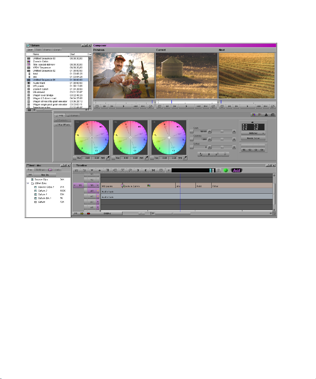
The Composer Window in Color Correction Mode
The Composer window in Color Correction mode is a three-monitor view.
This allows you to view material from three segments at once, making it easy
to compare material on a shot-by-shot basis. This three-monitor view shares
many of the features of the monitors in other modes but also includes several
features specific to Color Correction mode.
The following illustration shows the features of the Composer window in
Color Correction mode.
23
Page 24
Chapter 2 Understanding Color Correction Mode
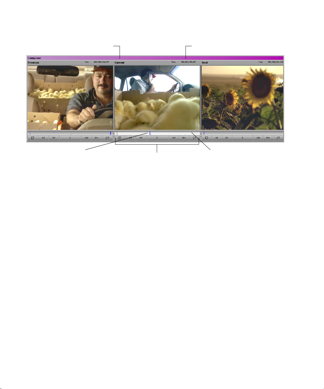
S
f
ource menu
By default, the monitors show (from left to right) the first frame of the
previous segment, the first frame of the current segment, and the first frame of
the next segment.
Activating Monitors
Composer Window buttons
Tracking In
Position barPosition indicator
ormation Display menu
24
Only one of the monitors is active at any one time. The position bar is
highlighted in the active monitor, and the image from the active monitor is
displayed in the Client monitor.
To activate a monitor:
t Click anywhere in the monitor’s image area, in the position bar, or on the
n
Tracking Information Display menu.
When you click one of the Composer Window buttons below a monitor, the
system activates that monitor and performs the action associated with the
button.
Page 25

Displaying Tracking Information
The Composer Window monitors in Color Correction mode have the same
options for displaying tracking information that are available in other modes.
To display tracking information in a Color Correction mode monitor:
t Select Tracking Information Display > format.
By default, the Tracking Information Display menu shows no information
until you select a tracking format.
For more information on tracking information display, see the chapter
“Viewing and Marking Footage” in the user’s guide or the editing guide for
your system or the Help.
Displaying Images in Monitors
The default Composer window for Color Correction mode is a three-monitor
view that shows images from three adjacent segments in the Timeline. You can
customize the monitor view to show images from other parts of the sequence,
to show specific images in a split-screen display, to hide the video, or to
display wide-screen (16:9) video. You can also customize a monitor to show
waveform or vectorscope information for the current segment.
The Composer Window in Color Correction Mode
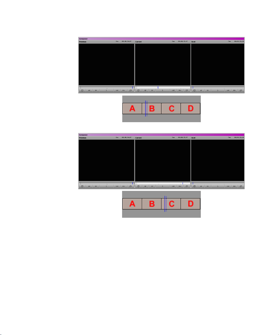
Understanding Default Monitor Display
By default, the center monitor shows the current segment (the segment the
position indicator is on in the Timeline). The left monitor shows the previous
segment (the segment before the current segment), and the right monitor
shows the next segment (the segment after the current segment).
When you move in the sequence by clicking a Composer Window button or by
moving the position indicator to a new segment in the Timeline, all three
monitors update to maintain the same relationship between displayed
segments.
The following illustrations show the default monitor display behavior.
25
Page 26
Chapter 2 Understanding Color Correction Mode
Example 1
The position indicator
is on segment B in the
Timeline. The three
monitors display
segments A, B, and C.
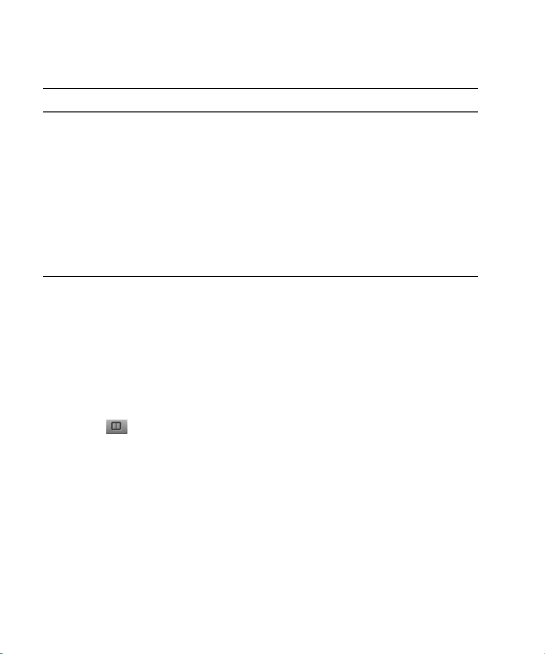
Example 2
The position indicator
has moved to segment
C. All three monitors
have updated so they
now display segments
B, C, and D.
ABC
BCD
Configuring Image Display in Monitors
You can configure each monitor to display those segments that are most useful
for making comparisons in your project.
To configure the display in a monitor:
t Click the monitor’s Source menu, and select one of the commands
described in the following table.
26
Page 27

The Composer Window in Color Correction Mode
Source Menu Commands
Command Description
Empty Displays no image (black).
Entire Sequence Makes the entire sequence available in the monitor. This is useful when you want to
compare shots from many different places in a sequence. For example, you can
display the current segment and the next segment in two monitors for immediate
shot-to-shot comparison and display the entire sequence in the third monitor so that
you can quickly navigate to any other part of the sequence you want to view. When
you change the current segment, the entire sequence updates to that segment.
You can use the Play Loop button in the Command palette to play the whole
n
sequence in the active monitor even if the monitor is not set to Entire
Sequence. For more information, see “Using the Play Loop Button in Color
Correction Mode” on page 32.
Reference Locks the current frame (the frame the position indicator is on) in the monitor. When
the other monitors update as you navigate in the Timeline, this frame continues to
display as a reference. This is useful if you want to use a specific place in your
sequence as a reference against which to compare all other shots, for example, a
segment that contains optimal skin tones.
To lock the current frame as a reference:
t Right-click (Windows) or Ctrl+Shift+click (Macintosh) in the Composer
window or the Color Correction tool, and select Reference Current.
Current Displays the current segment. This option is not available in the Source menu if
another monitor is already set to Current.
Previous Displays the segment immediately before the current segment.
Next Displays the segment immediately after the current segment.
Second Previous Displays the segment two segments before the current segment (the segment the
position indicator is on in the Timeline).
Second Next Displays the segment two segments after the current segment.
27
Page 28
Chapter 2 Understanding Color Correction Mode
Source Menu Commands (Continued)
Command Description
Waveform and
Vectorscope commands
• Quad Display
• RGB Histogram
•RGB Parade
• Vectorscope
• Y Waveform
•YC Waveform
• YCbCr Histogram
•YCbCr Parade
These commands configure the monitor as a Waveform monitor or Vectorscope
monitor. The system displays the information for the currently active monitor. For
more information, see “Working with the Waveform Monitors and Vectorscope
Monitor” on page 91.
Splitting the Image Display in Monitors
You can configure a monitor so it splits the screen to show the image before
and after the current color correction adjustments are applied.
n
The Dual Split display does not appear on the Client monitor.
To display uncorrected and corrected images in a split screen
(Dual Split):
28
t Click the Dual Split button for the monitor you want to display the split
screen.
The split-screen display appears in the monitor.
Page 29
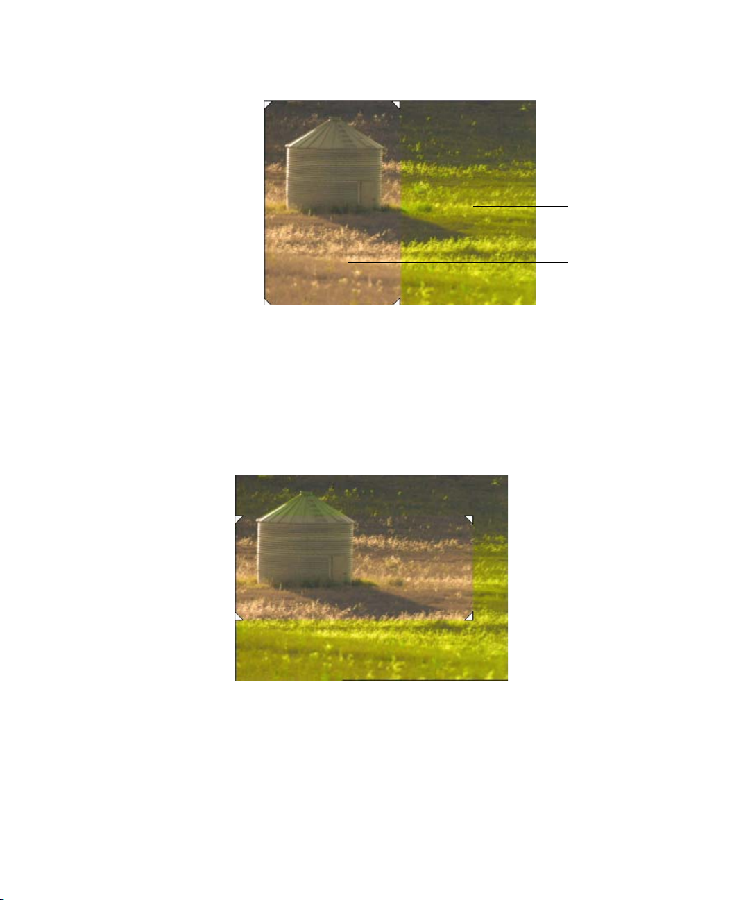
The Composer Window in Color Correction Mode
Image with currently
active corrections
applied
Uncorrected image
n
n
If you are reading a black-and-white hardcopy printout of this document, you
will find it useful to view the color images in the Help or in the online version
of this document on the online publications CD-ROM.
The uncorrected image appears on the left and the image with currently active
corrections applied appears on the right. You can resize the box that contains
the split-screen image by dragging its triangular handles in the monitor.
Triangular handle for
adjusting size of
uncorrected image
You can map the Dual Split button from the Command palette to the keyboard.
You can then switch Dual Split on and off with a single keystroke. For more
information, see “Using the Command Palette” in the chapter “Using Basic
Tools” in the user’s guide or the editing guide for your system or the Help.
29
Page 30

Chapter 2 Understanding Color Correction Mode
To cancel the Dual Split display:
t Click the Dual Split button for the monitor that contains the Dual Split
display.
The monitor returns to a single-image view.
Hiding the Video in Monitors
You can hide the video image area of the monitors at any time. When the video
is hidden, you see only the Source and Tracking Information Display menus
and the position bars for the monitors. The other parts of the Color Correction
toolset expand to fill the remainder of your screen. This might be a preferable
setting if you can perform your color correction tasks using only the Client
monitor to view your image.
To hide the video in the monitors:
t Right-click (Windows) or Ctrl+Shift+click (Macintosh) in the Composer
window, and select Hide Video.
When the video is hidden, a check mark appears beside the Hide Video
command.
To display the video again:
t Right-click (Windows) or Ctrl+Shift+click (Macintosh) in the Composer
window, and select Hide Video.
When the video is visible, there is no check mark beside the Hide Video
command.
Displaying 16:9 Video in Monitors
You can display wide-screen 16:9 video as well as standard format 4:3 video
in the monitors. However, you must switch to or from 16:9 display while in
editing mode and then select Color Correction mode. The 16:9 Video option is
unavailable in the shortcut menu when you are in Color Correction mode.
To display 16:9 video in the monitors:
t In editing mode, right-click (Windows) or Ctrl+Shift+click (Macintosh) in
the Composer window, and select 16:9 Video.
For information on selecting editing mode, see the section on customizing
the Composer window in the chapter “Viewing and Marking Footage” in
the user’s guide or the editing guide for your system or the Help.
30
Page 31

When the monitors are set to display 16:9 video, a check mark appears
beside the 16:9 Video command.
To display standard format 4:3 video again:
t In editing mode, right-click (Windows) or Ctrl+Shift+click (Macintosh) in
the Composer window, and select 16:9 Video.
When the monitors are set to display 4:3 video, there is no check mark
beside the 16:9 Video command.
Using the Composer Window Buttons
The buttons in the following illustration are available for each monitor in the
Composer window when you are using Color Correction mode. You can use
these buttons to play footage, move around in your sequence, display a splitscreen view, and remove effects.
The Composer Window in Color Correction Mode
n
All these buttons are available in the Command palette and can be mapped
from the Command palette to the keyboard using the procedure described in
“Using the Command Palette” in the chapter “Using Basic Tools” in the user’s
guide or the editing guide for your system or the Help.
You cannot map other buttons to the Composer Window button locations of the
Color Correction toolset.
The following table describes these buttons in detail and indicates their
location within the Command palette.
31
Page 32

Chapter 2 Understanding Color Correction Mode
Composer Window Buttons
Button Description
Command
Palette Tab
Dual Split Splits the screen in the monitor to show the image
before and after the current Color Correction settings
are applied. For more information, see “Splitting the
Image Display in Monitors” on page 28.
The Dual Split display does not appear in the
n
Client monitor.
Go to Previous Shot Moves the position indicator to the first frame of the
previous shot in the topmost selected video track.
Go to Next Shot Moves the position indicator to the first frame of the
next shot in the topmost selected video track.
Play Plays the material in the monitor from the current
position of the position indicator to the end of the
segment. If Sequence is selected in the Source menu,
clicking this button plays the material from the current
position of the position bar to the end of the sequence.
Clicking the button again stops play.
Go to Previous
Uncorrected Shot
Go to Next
Uncorrected Shot
Moves the position indicator to the first frame of the
last segment before the current segment in the topmost
selected video track that has not been color corrected.
Moves the position bar to the first frame of the first
segment after the current segment in the topmost
selected video track that has not been color corrected.
Other
Move
Move
Play
CC
CC
Remove Effect Removes the color correction on the current segment. FX
Using the Play Loop Button in Color Correction Mode
The Play Loop button has a specialized function in Color Correction mode.
The Play Loop button does not appear in the Composer window but does
control the playback of material in the Composer window. You can access the
Play Loop button from the Play tab of the Command palette or from the
keyboard if it has been mapped to a keyboard location.
32
Page 33

The Client Monitor in Color Correction Mode
When you click the Play Loop button, the system plays the whole sequence in
the active monitor, starting from the current position of the position indicator.
Playback is not limited to the current segment alone, regardless of the Source
menu command selected for the monitor. This is useful whenever you want to
view the whole sequence quickly without switching monitors or making a new
Source menu choice.
The Client Monitor in Color Correction Mode
The Client monitor can be an important tool for color correction since it allows
you to see your corrections as they will appear when output and displayed on a
television screen. Your system’s Edit monitor does not have exactly the same
color and luminance display characteristics as a television monitor.
n
With some Avid systems, to use a Client monitor requires that you select the
“High Performance (more simultaneous effects)” option in the Video Display
Settings dialog box. For information about the Video Display Settings dialog
box, see the effects guide for your system or the Help. For more information on
connecting a Client monitor, see the Help.
When you are using Color Correction mode, the Client monitor displays the
image that is in the currently active monitor in the Composer window. By
switching from one monitor to another in the Composer window, you can
quickly compare whichever three images are currently displayed in the
monitors. For more information on switching between monitors, see
“Activating Monitors” on page 24.
Some systems support Dual Split display in the Client monitor. For those
systems, when you select Dual Split for the active monitor, the split-screen
display also appears in the Client monitor. This allows you to compare
uncorrected and corrected versions of the same segment within the Client
monitor. If you right-click (Windows) or Ctrl+Shift+click (Macintosh) the
Color Correction tool, and select Dual Split with Reference, the split-screen
display allows you to compare a shot with the current reference shot within the
Client monitor. For more information on using dual-split options, see
“Splitting the Image Display in Monitors” on page 28.
33
Page 34

Chapter 2 Understanding Color Correction Mode
n
If the Dual Split display does not appear in the Client monitor, your system
might not support this feature. If it does, make sure that Show Graphics on
Client Display is selected in the Interface Settings dialog box. See the user’s
guide or the editing guide for your system or the Help.
The Color Correction Tool
In Color Correction mode, you make adjustments in color using the Color
Correction tool.
The following illustration shows the Color Correction tool in its default
configuration.
Group tabs
Enable buttons
Color Match control. For more information, see
“Using the Color Match Control” on page 59.
Color Correction
Tool buttons
Subdividing tabs
Color Correction bucketsColor adjustment sliders
Working with the Group and Subdividing Tabs
The Color Correction tool contains two group tabs, the HSL (Hue, Saturation,
Luminance) group tab and the Curves group tab.
HSL group tab Curves group tab
HSL group
subdividing tabs
34
Page 35

Within the HSL group are two tabs on the left side of the tool that subdivide
the controls for that group. The Curves group has no subdividing tabs. For
more information, see “Understanding Color Correction Groups” on page 19.
Displaying a Group Tab
To display a color correction group tab:
t Click the tab in the area containing the group name.
The Color Correction Tool
n
n
Displaying an HSL Subdividing Tab
Do not click the Enable button when you want to display a color correction
group tab.
The tab is highlighted and moves to the front, and the specific controls for
that tab appear.
You can switch between the group tabs using the Page Down key or the Page
Up key.
For detailed information on adjusting color using the controls within the color
correction groups, see Chapter 3.
To display an HSL subdividing tab:
1. Click the HSL group tab in the area containing the group name.
2. Click the subdividing tab in the area that contains the subdivision name.
Click in this area of a tab to display the tab.
Do not click the Enable button.
The subdividing tab is highlighted and moves to the front, and the specific
controls for that tab appear.
35
Page 36

Chapter 2 Understanding Color Correction Mode
Understanding Interaction Between Color Correction Groups
Understanding how the color correction groups work together is important.
Adjustments made in each group are applied cumulatively to the current
segment and its related material. If you make an adjustment in one group and
then go on to make another adjustment in a different group, the image will
show the cumulative effect of both adjustments.
This behavior provides you with a great deal of flexibility. For example, if you
are unhappy with some of your adjustments, you can disable the group that
contains those adjustments or reset its controls to default settings without
disrupting other adjustments. The following illustration shows an example of
this kind of control over color correction groups.
Enable button for
HSL tab is turned on.
The Green and Blue ChromaCurve graphs are adjusted, but the Curves tab is turned off. The Curves tab
adjustments are not currently applied to the segment. Adjustments made in the HSL tab are applied to the
segment because the HSL tab is turned on, even though the HSL controls are not currently visible.
Enable button for Curves
tab is turned off.
For more information on enabling, disabling, and resetting the groups, see
“Working with the Enable Buttons” on page 37.
n
If you make adjustments in both groups, keep in mind how the cumulative
adjustments will affect the final image. Adjustments might accumulate, or
cancel each other out, in ways that you do not want. Keep each stage of your
correction distinct, and do not duplicate the same adjustment in both groups.
36
Page 37

Working with the Enable Buttons
In the Color Correction tool, each group tab, subdividing tab, and individual
control has an Enable button. These buttons provide an immediate visual guide
to the status of the controls while you are making corrections. They also allow
you to turn controls on and off in various combinations and quickly reset
controls to their default values.
The Color Correction Tool
n
Turning Controls On or Off
Adjustments to the Gain, Gamma, and Setup controls in the Hue Offsets
subtab of the HSL tab enable both the Hue Offsets and the Controls subtabs.
This behavior is not consistent with the normal interaction between Enable
buttons but is necessary to ensure that color corrections will conform correctly
if you move your project to Avid Symphony. To turn off adjustments to the
Gain, Gamma, and Setup controls you must disable the controls individually
by clicking one or more of their Enable buttons, or you must disable the entire
HSL tab by clicking the HSL tab Enable button.
To turn off adjustments to the Gain, Gamma, and Setup controls you must
disable the entire HSL tab. However, you can reset the Gain, Gamma, and
Setup controls
To turn a control or tabbed group of controls on, do one of the following:
t Click the Enable button for the control or tabbed group of controls.
t Adjust any individual control that is linked to the Enable button.
The Enable button changes to pink, and the control or tabbed group of
controls becomes active. The system includes the adjustments in that
control or group of controls when calculating the corrected color.
To turn a control or tab off:
t Click the Enable button for the control or tab.
The Enable button changes to gray.
37
Page 38

Chapter 2 Understanding Color Correction Mode
Resetting Controls
To reset a control or a tabbed group of controls to its default values:
1. Display the control or group of controls you want to reset.
2. Alt+click (Windows) or Option+click (Macintosh) the Enable button for
that control or group of controls.
The Enable button changes to gray, and all controls linked to that button
return to their default values.
n
Understanding Interaction Between Enable Buttons
You cannot reset controls not currently displayed. If you Alt+click (Windows)
or Option+click (Macintosh) the Enable button for a tab whose controls are
not currently displayed, you display the controls but do not reset them.
Alt+click (Windows) or Option+click (Macintosh) the button again to reset the
controls.
The Enable buttons are linked in a hierarchical relationship that mirrors the
relationship of the tabs themselves. When you change the status of an Enable
button, the change can affect several levels of the hierarchy.
When you Alt+click (Windows) or Option+click (Macintosh) an Enable
button to reset controls, you automatically reset all controls at a lower level in
the hierarchy. For example, if you Alt+click (Windows) or Option+click
(Macintosh) the Enable button for the Red ChromaCurve
Curves tab, only that one control is reset to its default value. However, if you
Alt+click (Windows) or Option+click (Macintosh) the Enable button for the
Curves tab, all the controls in the Curves tab will reset to their default values.
When you turn an Enable button off, the system stops including controls
below that button in the hierarchy when it calculates the corrected color for the
segment. Individual controls below that button retain their values and can be
reactivated at any time. Their Enable buttons remain pink.
™
graph in the
38
Page 39

The Curves tab Enable button is turned off, so none of the adjustments in the Curves tab
are applied to the correction. Individual controls inside the tab retain their values and can
be reactivated by clicking the Curves tab Enable button again.
Using the Color Correction Tool Buttons
The Color Correction Tool
Color Correction
Effect Template
button
In addition to the Enable buttons, and specific control buttons within groups,
the Color Correction tool has a group of buttons on the right side that control
several important operations.
Comments button
Correction Mode
Settings button
Safe Color
Settings button
Use these buttons to:
• Create Color Correction effect templates.
For more information, see “Working with Color Correction Effect
Templates” on page 43.
• Customize the operation of Avid Color Correction.
For more information, see “Customizing Color Correction Mode
Settings” on page 40.
39
Page 40

Chapter 2 Understanding Color Correction Mode
• Set Safe Color limits.
For more information, see Chapter 5.
• Add comments to color-corrected segments.
For more information, see “Adding Comments to Color Correction
Effects” on page 41.
Customizing Color Correction Mode Settings
You can customize the appearance and behavior of Color Correction mode by
selecting options in the Correction Mode Settings dialog box.
To customize Color Correction mode:
1. Do one of the following:
t In the Color Correction tool, click the Correction Mode Settings
button.
t In the Project window, click the Settings tab, and then double-click
Correction.
The Correction Mode Settings dialog box opens.
40
2. Click the tab that contains the options you want.
-The Features tab controls several aspects of the appearance and
behavior of Color Correction mode. The following table describes the
options available in the Features tab of the Correction Mode Settings
dialog box.
-The AutoCorrect tab contains pop-up menus for defining which
automatic color corrections are made when you apply the Color
Correction effect from the Effect Palette. For information on the
options available in the AutoCorrect tab of the Correction Mode
Settings dialog box, see “Selecting AutoCorrect Options” on
page 102.
3. Select the options you want.
4. Click OK.
Page 41

The Color Correction Tool
Correction Mode Settings
Feature Tab Options
Option Description
Saved Color Labels Select an item from the pop-up menu to control how custom colors are named in
bins. For information on saving custom colors, see “Saving Custom Colors to a Bin”
on page 66.
• None When selected, the system does not supply a name.
• RGB When selected, the system uses the 8-bit values for the red, green, and blue
components as the name.
• Name When selected, the system uses the name from the standard HTML color scheme
that most closely matches the color you are saving.
• Name and RGB When selected, the system uses both the Name and the RGB information as the
name. This is the default option.
Eyedropper 3 x 3
Averaging
Show Eyedropper Info When this option is selected, the numerical RGB values appear on the color
Eyedropper Picks from
Anywhere in Application
When this option is selected, the system calculates the color value to pick by
averaging the values of a 3 x 3 sample of pixels centered on the eyedropper’s
position. This is often useful for picking up a color accurately by sight because it
compensates for shifts in color value from one pixel to another. When this option is
deselected, the system selects the color value of the exact pixel at the eyedropper’s
position.
swatches in the Color Match controls.
When this option is selected, the eyedropper can pick a color from anywhere within
the Avid application, for example the swatch for a custom color in a bin.
Adding Comments to Color Correction Effects
You can add comments to color-corrected segments to assist you in your work.
For example, you might want to briefly note the type of adjustment you made
to a segment or to make notes during a preliminary correction pass of ideas for
adjustments to be done later during a final pass.
The Comments button indicates whether a comment is present on a segment.
If the position indicator is on a segment that has a comment, the icon on the
Comments button is yellow.
41
Page 42
Chapter 2 Understanding Color Correction Mode
If the position indicator is on a segment that has no comment, the icon on the
Comments button is not yellow.
To add a comment to a segment:
1. If you are not already in Color Correction mode, do one of the following:
t Select Toolset > Color Correction.
t Press Shift+F8.
2. Move the position indicator to the segment to which you want to add a
comment.
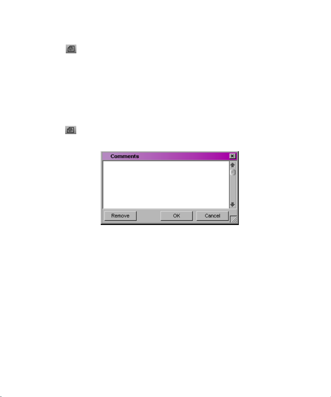
3. In the Color Correction tool, click the Comments button.
The Comments dialog box opens.
42
4. Type your comment in the text window, and click OK.
To remove a comment:
1. If you are not already in Color Correction mode, do one of the following:
t Select Toolset > Color Correction.
t Press Shift+F8.
2. Move the position indicator to the segment from which you want to
remove the comment.
3. In the Color Correction tool, click the Comments button.
The Comments dialog box opens.
4. Click Remove.
Page 43

Working with Color Correction Effect Templates
To view or edit a comment in the Comments dialog box:
1. If you are not already in Color Correction mode, do one of the following:
t Select Toolset > Color Correction.
t Press Shift+F8.
2. Move the position indicator to the segment for which you want to view the
comment.
3. In the Color Correction tool, click the Comments button.
The Comments dialog box opens and displays the text of the comment.
4. (Option) To edit the comment, click in the text window and make your
edits using standard word processing procedures.
Working with Color Correction Effect Templates
Avid Color Correction offers the following versions of Color Correction effect
templates:
• The Color Correction buckets provide an easily accessible location within
the Color Correction tool for the short-term storage of Color Correction
effect templates.
• The Color Correction Effect Template button allows you to create a
template for any color correction and save it to a bin in the same way that
you save other kinds of effect templates. The Save Correction button in
the CC tab of the Command palette performs the same function.
Like templates for other effects, Color Correction effect templates save all the
adjustment values for a color correction so you can apply those values quickly
to another segment. You can apply all the values at once by dragging the
template into the monitor containing the current segment, or you can apply the
values for the controls in a single tab in the Color Correction tool by dragging
the template onto the tab that contains the group of controls you want to
change.
You can also apply a Color Correction effect template to multiple segments at
once by selecting the segments and then double-clicking the effect template
icon in the bin or in the Effect Palette. To do this, you must be in editing or
Effects mode.
43
Page 44

Chapter 2 Understanding Color Correction Mode
n
You can also save custom colors to bins. For more information, see “Using the
Color Match Control” on page 59.
Understanding How Color Correction Effect Templates Save Settings
When you create a Color Correction effect template, the system saves all the
Color Correction settings for the segment. The system remembers both the
values set for each control and the status of each Enable button.
Templates saved to a bin or a bucket do not update when you make new
adjustments to the segment. To save new adjustments, you must save a new
template to a bin or a bucket.
n
You can specify which settings you apply in a template by dragging the
template to the active tab in the Color Correction tool. This changes only
those settings contained within that tab. Using this method, you can, for
example, apply settings one tab at a time without applying any other settings
that might also be saved in a template.
Saving a Color Correction Effect Template to a Bin
You can save a Color Correction effect template to a bin using either the Color
Correction Effect Template button in the Color Correction tool or the Save
Correction button in the CC tab of the Command palette.
44
Color correction templates saved to a bin are saved permanently, unlike
templates saved to a bucket, which are not saved beyond the current working
session.
To save a Color Correction effect template to a bin:
1. If you are not already in Color Correction mode, do one of the following:
t Select Toolset > Color Correction.
t Press Shift+F8.
2. Make sure that the position indicator is in the segment that contains the
settings you want to save.
3. Do one of the following:
t Click the Color Correction Effect Template button, press and hold the
mouse button, and then drag the effect icon to a bin.
Page 45

Working with Color Correction Effect Templates
t With Active Palette selected in the Command palette, click the Save
Correction button in the CC tab.
t If the Save Correction button is mapped to a key, press that key.
Effect icons for open
bins are also displayed
in the Effect Palette.
A new effect template appears in the bin, containing all the color
correction adjustment values for the segment. The new effect template is
identified in the bin by its effect icon. By default, the system names the
template using the clip name of the segment.
4. (Option) To rename the template, click the template name and type a new
name.
Saving a Color Correction Effect Template to a Bucket
The Color Correction tool provides four buckets, located below the Color
Match control, that you can use to save Color Correction effect templates for
the duration of a working session. You can then apply the template quickly to
any segment. The buckets are labeled C1 through C4.
n
You can map any of the Color Correction buckets from the CC tab in the
Command palette to the keyboard, for example, to a function key, using the
standard procedures for mapping buttons described in the chapter “Using
Basic Tools” in the user’s guide or the editing guide for your system or the
Help.
The following illustration shows the Color Correction buckets.
45
Page 46

Chapter 2 Understanding Color Correction Mode
To save a Color Correction effect template in a bucket:
1. If you are not already in Color Correction mode, do one of the following:
t Select Toolset > Color Correction.
t Press Shift+F8.
2. Make sure that the position indicator is in the segment that contains the
adjustment values you want to save.
3. Alt+click (Windows) or Option+click (Macintosh) the bucket in which
you want to save the template.
Select a bucket from the range C1 to C4. Empty buckets have a blank icon
holder above them. If you Alt+click (Windows) or Option+click
(Macintosh) a bucket that already contains a template, you overwrite the
previous template with the new adjustment values.
Icon holders
Buckets
The values are saved as a template and a Color Correction icon appears in
the icon holder above the Color Correction bucket.
n
Color Correction effect templates saved to buckets do not remain from one
session to another. When you end your session, the system deletes the
templates. You can save an effect template in a bucket permanently by clicking
the Color Correction icon in the icon holder, and dragging it to a bin.
Applying Color Correction Effect Templates
For help, see “Entering
and Exiting Color
Correction Mode” on
page 21.
n
46
To apply all adjustment values in a Color Correction effect template to the
current segment, do one of the following in Color Correction mode:
t Click the effect icon for the template in the bin, the Effect Palette, or the
Color Correction bucket icon holder, and drag it to the monitor containing
the current segment.
For tips on working with templates in the Effect Palette, see “Saving a Color
Correction Effect Template to a Bin” on page 44.
Page 47

Working with Color Correction Effect Templates
t Select the template in the bin or the Effect Palette, and then press Enter
(Windows) or Return (Macintosh).
t Click the appropriate Color Correction bucket (for example, C1).
t If you have mapped the Color Correction bucket to the keyboard, press the
appropriate key.
The system applies all the Color Correction adjustments in the template to
the segment that is the current location of the position indicator.
To apply adjustment values from a Color Correction effect template
selectively to a single tab of color correction controls:
1. In the Color Correction tool, click the tab to which you want to apply the
template.
2. Click the effect icon for the template in the bin, the Effect Palette, or the
Color Correction bucket icon holder, drag it to the tab, and drop it
anywhere in the tab.
The controls in that tab update to reflect the values in the template. Other
color correction controls are not affected.
n
n
If you apply template settings to a subdividing tab in the HSL group, the image
in the monitor does not reflect those settings until you enable the HSL group
tab.
If you apply a saved Color Correction effect template to a segment that
already has a color correction, you overwrite the existing correction. The
existing Color Correction settings are lost. Make sure you want to replace the
existing correction before you apply a saved Color Correction effect template
to a clip that already has a correction. You can use the Undo command to
undo the effect of a Color Correction effect template. However, once the Undo
command is no longer available, you cannot recover the original Color
Correction settings.
To apply all adjustment values in a Color Correction effect template to
multiple segments:
1. In editing or Effect mode, select the segment to which you want to apply
the Color Correction effect template.
For more information, see “Applying an Effect to Multiple Segments” in
the chapter “Basics of Effects Editing” in the effects guide for your Avid
application.
2. Open the bin that contains the Color Correction effect template.
47
Page 48

Chapter 2 Understanding Color Correction Mode
3. Double-click the Color Correction effect template icon in the bin or in the
Effect Palette.
The application applies the Color Correction effect template to each of the
selected segments.
Working with Color Correction Effect Templates in the Effect Palette
The following list of reminders and suggestions can help you work quickly
when you are using saved Color Correction effect templates in the Effect
Palette.
• Press Ctrl+8 (Windows) or k+8 (Macintosh) to open the Effect Palette or
to make the Effect Palette active.
The Effect Palette becomes inactive whenever you perform an action in
another area of the interface (for example, when you move the position
indicator in the Timeline). Pressing Ctrl+8 (Windows) or k+8
(Macintosh) is a quick keyboard method for reactivating the Effect
Palette. The Effect Palette must be active before you can use it to apply a
Color Correction effect template.
• Use the Tab key to make one side or the other of the Effect Palette active.
48
For example, if the effect categories list on the left side of the Effect
Palette is active, press the Tab key to activate the list of templates on the
right side. Press the Tab key again to activate the effect categories list.
Clicking a specific item in either list also activates that side of the Effect
Palette.
• To display a group of effect templates in the Effect Palette, select the bin
or the color-corrected sequence that contains the templates in the effect
categories list on the left side of the palette.
• Use the Up Arrow and Down Arrow keys to move through the active list.
For example, you can quickly move from the most recent correction to the
third most recent in the list by pressing the Down Arrow key twice.
• The Effect Palette remembers the currently selected item in the list of
corrections even when it becomes inactive or is closed.
For example, if you have the most recent correction in the list selected and
then leave the Effect Palette to perform another operation or close the
Effect Palette, that correction will be the selected correction when you
reactivate or reopen the Effect Palette.
Page 49

Working with Color Correction Effect Templates
This makes it easy to apply the same template successively to a number of
segments, especially if you have navigation buttons such as Fast Forward,
Rewind, Go to Next Uncorrected Shot, and Go to Previous Uncorrected
Shot mapped to the keyboard. Once you have the template you want
selected in the Effect Palette, you simply navigate to another segment,
press Ctrl+8 (Windows) or k+8 (Macintosh) to activate the Effect
Palette, and then press Enter (Windows) or Return (Macintosh) to apply
the template.
49
Page 50

Chapter 2 Understanding Color Correction Mode
50
Page 51

Chapter 3
Performing Color Corrections
This chapter describes procedures for making color corrections and provides a
complete explanation of all the controls in the Color Correction tool.
• General Workflow for Making Color Corrections
• Using Automatic Color Corrections
• Using the Color Match Control
• The HSL (Hue, Saturation, Luminance) Group
• The Curves Group
• Working with the Waveform Monitors and Vectorscope Monitor
• Applying Color Corrections to an Entire Sequence
• Using Color Correction Effects in the Effect Palette
General Workflow for Making Color Corrections
Avid Color Correction gives you a great deal of flexibility when you make
color corrections. The exact workflow that you employ will depend on your
individual methods, your degree of familiarity with the color correction
controls, and the requirements of your project. However, the basic steps to take
when making a correction will be similar for all users.
The following procedure outlines a typical color correction operation. You can
adapt the exact order in which steps are performed or repeated to conform to
your particular needs.
Page 52

Chapter 3 Performing Color Corrections
To color correct a sequence:
1. In editing mode, load the sequence.
2. Do one of the following:
t Select Toolset > Color Correction.
t Press Shift+F8.
The Color Correction toolset appears.
3. (Option) If necessary, configure the toolset and adjust Correction Mode
Settings to suit the requirements of your project and editing style. For
more information, see Chapter 2.
4. Preview the material in the sequence to develop a sense of the kinds of
corrections that are needed and the approach you will use to make them.
For example, you might look for a shot that you would like to use as a
reference for your adjustments and lock that shot in one of the monitors.
For general guidance on what to look for when previewing material, see
Chapter 4.
n
You might prefer to preview extensively and plan your corrections in advance.
If you have more color correcting experience, you might prefer to work by
moving back and forth frequently between making corrections and assessing
the material on which they are working.
5. Make sure that the Record Track button for the track on which you want to
make corrections is the topmost selected button in the Track Selector
panel in the Timeline.
You can color correct any number of tracks, including nested tracks by
stepping into the nest. However, you can correct only one track at a time.
Color correction is applied to the topmost selected track in a sequence.
6. Use the Composer Window buttons or the position indicator in the
Timeline to move to a segment you want to correct.
7. Click the appropriate tabs in the Color Correction tool to display the
controls you want to use to make the correction.
52
Page 53

8. Use the automatic color correction features or adjust the color correction
controls manually until you are satisfied with the correction.
Remember that you can repeat steps 7 and 8 to make successive
adjustments using several different groups of controls and to selectively
turn them on and off while you assess their effect on the segment. You can
use the Dual Split button in the monitors to view corrected and
uncorrected images side by side.
9. (Option) Add a comment for the correction.
10. Repeat steps 5 through 9 for each segment you want to correct.
11. When you are satisfied with the corrections throughout the sequence,
make a selection from the Toolset menu to exit Color Correction mode
and return to other editing operations.
Using Automatic Color Corrections
Both color correction groups include buttons that allow you to make automatic
color corrections to correct contrast problems, balance color, or remove color
casts by identifying areas of an image that should be color neutral.
Using Automatic Color Corrections
You can also apply up to three automatic color corrections in a single
operation by selecting options in the AutoCorrect tab of the Correction Mode
Settings dialog box and applying the Color Correction effect from the Effect
Palette to one or more segments in a sequence. For more information, see
“Using Color Correction Effects in the Effect Palette” on page 102.
The Color Match control also corrects automatically by adjusting an image so
that a poor color value matches a better one. You select the colors on which
you want Color Match to operate using an eyedropper. For more information,
see “Using the Color Match Control” on page 59.
Understanding Automatic Color Correction
Automatic color correction simplifies the work of correcting common color
problems in video images. When you use one of the automatic color
corrections, Avid Color Correction analyzes the existing color characteristics
of an image and makes adjustments to color correction controls that usually
eliminate or at least significantly reduce a specific color problem.
53
Page 54

Chapter 3 Performing Color Corrections
You will often want to begin your color correction work by using automatic
color corrections, especially if you do not have time for detailed manual
adjustments, if you only need to correct basic color problems such as color
casts, or if you lack experience with the manual controls in the Color
Correction tool.
Since automatic color correction adjusts controls in the Color Correction tool
just as you would when making manual corrections, you are always free to
make additional adjustments manually if you need to fine-tune the correction.
Also, automatic color corrections can help you learn how to recognize color
problems in images and what kinds of adjustments you might make to correct
images manually. For example, if the Auto Balance automatic correction in the
Hue Offsets subdividing tab adjusts an image by adding yellow in the
ChromaWheels, then the analysis of that image revealed a blue color cast.
Automatic color corrections operate within normal limits for legal video
levels. For example, an automatic color correction will not make an
adjustment that takes a significant area of an image beyond legal luminance
levels.
Adjusting Contrast and Balance Automatically
You can adjust the contrast and balance the color automatically for an image
simply by clicking buttons. An automatic contrast adjustment expands the
tonal range of the image, which usually improves sharpness and detail. An
automatic balance adjustment evens out the influence of the different color
channels in the image, which usually greatly reduces or even eliminates any
color cast.
Automatic contrast and balance buttons appear in the Color Correction tool in
the following locations:
• The Hue Offsets subdividing tab of the HSL tab, as shown in the
following illustration:
Auto White button
Auto Balance button
Auto Black button
54
Auto Contrast button
Page 55

Using Automatic Color Corrections
• The Curves tab, as shown in the following illustration:
Auto Contrast button
Auto Balance button
To make an automatic contrast or balance adjustment:
1. If you have not already done so:
a. Move the position indicator to the segment you want to correct.
b. Click the Color Correction group tab or subdividing tab that contains
the automatic correction button you want to use.
2. Click the appropriate automatic correction button.
The system analyzes the currently selected frame in the segment and
adjusts the appropriate color correction controls. The following table lists
the available contrast and balance buttons and describes their function.
Automatic Contrast and Balance Buttons
Location in Color
Button
Auto Balance HSL tab, Hue Offsets
Auto Black HSL tab, Hue Offsets
Auto Contrast HSL tab, Hue Offsets
Auto White HSL tab, Hue Offsets
Auto Balance Curves tab Makes adjustments to the Red, Green, and Blue curves to balance the
Correction Tool Description
Makes adjustments to the three ChromaWheels to balance the colors
subdividing tab
subdividing tab
subdividing tab
subdividing tab
in the image. This eliminates any color cast for most images.
Makes an adjustment to the Setup slider control that makes the darkest
areas of the image as dark as possible.
Makes adjustments to the Gain and Setup slider controls to maximize
the tonal range in the image. The brightest areas of the image are made
as bright as possible and the darkest areas of the image are made as
dark as possible.
Makes an adjustment to the Gain slider control that makes the
brightest areas of the image as bright as possible.
colors in the image. This eliminates any color cast for most images.
55
Page 56

Chapter 3 Performing Color Corrections
Automatic Contrast and Balance Buttons
Location in Color
Button
Auto Contrast Curves tab Makes an adjustment to the Master curve to maximize the tonal range
Correction Tool Description
in the image. The brightest areas of the image and made as bright as
possible and the darkest areas of the image are made as dark as
possible.
Using the Remove Color Cast Buttons
You can remove a color cast automatically by clicking a Remove Color Cast
button and using an eyedropper to identify an area in your image that you want
to be color neutral (white, black, or a shade of gray). Avid Color Correction
analyzes the current color characteristics of the area you have selected and
then adjusts color correction controls to make that area color neutral.
Remove Color Cast buttons provide more precise control over color cast
removal than Auto Balance buttons because their adjustments are limited
either by luminance range or by the impact that they have on existing curve
graphs. However, Remove Color Cast buttons are only useful when you are
working with an image that has areas that should be color neutral.
56
Remove Color Cast buttons appear in the Color Correction tool in the
following locations:
• Below each of the three ChromaWheels in the Hue Offsets subdividing
tab of the HSL tab, as shown in the following illustration:
Remove Color Cast button
• In the Curves tab, as shown in the following illustration:
Remove Color Cast button
Page 57

Using Automatic Color Corrections
Each ChromaWheel Remove Color Cast button is associated with the wheel
above it. Adjustments are made only to that wheel; only the parts of the image
that fall within the luminance range controlled by that wheel are changed. You
choose which ChromaWheel to adjust based on the luminance level of the area
you want to identify, as follows:
• To make white or light gray areas of an image color neutral and remove a
cast throughout the lightest part of the image, use the Remove Color Cast
button below the Highlights ChromaWheel.
• To make mid-gray areas of an image color neutral and remove a cast
throughout the midtones of the image, use the Remove Color Cast button
below the Midtones ChromaWheel.
• To make black or dark gray areas of an image color neutral and remove a
cast throughout the darkest parts of the image, use the Remove Color Cast
button below the Shadows ChromaWheel.
The Curves tab Remove Color Cast button works by adding a point to each of
the Red, Green, and Blue curves that makes the area you identify with the
eyedropper color neutral. You can use the Curves tab Remove Color Cast
button repeatedly to identify multiple areas that you want to be color neutral.
Each new use adds another point to each of the three curves. (You can add new
points up to the 16 point limit, although once several points are distributed
along the curve, further points are unlikely to improve the image
significantly).
The effect of each added point on the image as a whole varies depending on
the shape of the entire curve. In general, each new point affects the image most
in areas with similar luminance values to the area you identify with the
eyedropper, and affects the image least in areas with very different luminance
values.
To use a Remove Color Cast button:
1. If you have not already done so, move the position indicator to the
segment you want to correct.
2. Do one of the following:
t Click the Remove Color Cast button below a ChromaWheel in the
Hue Offsets subdividing tab of the HSL tab.
t Click the Remove Color Cast button in the Curves tab.
The button appears highlighted.
57
Page 58

Chapter 3 Performing Color Corrections
3. Drag the pointer into the image.
The pointer changes to an eyedropper.
4. Continue to drag the eyedropper until it is over the part of the image you
want to become color neutral, and then release the mouse button.
Avid Color Correction analyzes the part of the image you have identified
and adjusts the controls to remove the color cast.
Considerations When Using Automatic Color Correction
Although automatic color corrections are much simpler to learn and perform
than manual corrections, practice and experience will still improve your ability
to correct a range of images with different color characteristics. If one set of
automatic corrections does not produce good results, remove it and try a
different combination. Remember also that some images with extreme color
characteristics might require manual correction in addition to or instead of
automatic correction.
The following tips and suggestions will help you to achieve the best possible
results when using automatic color correction:
58
• The Auto Contrast correction is most useful for images that should have
both areas of strong highlight (white or close to white) and areas of strong
shadow (black or close to black). If you make an Auto Contrast correction
on an image that should not have such a full tonal range (many close-ups
fall into this category), the correction might introduce too much contrast.
When an image requires strong highlights but not strong shadows (or the
reverse), you can use the Auto White or the Auto Black button to set the
white or black point without making the overall range of tones too
extreme.
• When you perform both an Auto Contrast and an Auto Balance
correction, the order in which you perform these two operations affects
the final quality of the correction. In most cases, you will achieve the best
results for most images by doing the following:
- In the Hue Offsets subdividing tab of the HSL tab, use Auto Contrast
first, and then use Auto Balance
- In the Curves tab, use Auto Balance first, and then use Auto Contrast
• There is usually no gain in performing an automatic correction more than
once on the same image, even if the second correction would be made in a
different group from the first. For example, once you have performed an
Page 59

Using the Color Match Control
Auto Balance in the Curves tab, you will not usually see any improvement
in the color balance of the image if you perform a second Auto Balance
either in the Curves tab or in the Hue Offsets subdividing tab of the HSL
tab.
• If an Auto Contrast and Auto Balance combination has improved an
image but some color cast remains, you can often fine-tune the correction
using one or more of the Remove Color Cast buttons.
• Automatic corrections you make in the Hue Offsets subdividing tab of the
HSL tab and those you make in the Curves tab do not produce identical
results for most images (and might produce markedly different results for
some images). This is because the methods for calculating the corrections
are different and because the controls that are being adjusted operate
differently. Automatic corrections in the Curves tab often work well for
correcting basic problems caused by incorrect camera color balancing.
Automatic corrections in the Hue Offsets subdividing tab of the HSL tab
are often better for more extreme problems such as bad lighting
conditions. However, there are no rules that cover all situations. If
automatic correction in one color correction group does not yield good
results, remove it and try a correction in the other group.
Using the Color Match Control
Both Color Correction groups include a Color Match control. This control
allows you to quickly make a correction by selecting input and output colors
from your images, from the Windows Color dialog box, or from the
Macintosh
in Application” option in the Correction Mode Settings dialog box, you can
also select colors from any other location within your Avid application, such
as a custom color swatch saved in a bin.
When you use the Color Match control, the system replaces the input color
value with the output color value and adjusts all the other color values in the
image proportionally. The system also automatically adjusts the other controls
in the group to reflect the change. You can set the combination of color
channels or components the system uses to determine the match by making
menu selections.
For example, if you want to replace the blue sky tone in one image with that in
another to match the two shots, you can use the Color Match control to pick
the two colors and automate the color adjustment.
®
Color Picker. If you select the “Eyedropper Picks from Anywhere
59
Page 60

Chapter 3 Performing Color Corrections
When you are working in the Curves group, the Color Match control also
™
includes the NaturalMatch
feature. NaturalMatch allows you to replace the
hue values in an image with new output values without distorting the
saturation and luminance values in the image.
You can also Alt+drag (Windows) or Option+drag (Macintosh) colors to a bin
and save them as custom colors. You can then click a custom color and drag it
into the Color Match control at any time, or, if you have the “Eyedropper Picks
from Anywhere in Application” option selected, you can select a custom color
from its swatch in the bin using the eyedropper.
The following illustration shows the Color Match control.
Input color
swatch
Match Type
button
Output color
swatch
Match Color
button
Making a Correction with the Color Match Control
For complete
information on the
Correction Mode
Settings dialog box, see
“Customizing Color
Correction Mode
Settings” on page 40.
60
To make a correction using the Color Match control:
1. In the Color Correction tool, click the tab that includes the Color Match
control with which you want to work.
For help, see “Entering and Exiting Color Correction Mode” on page 21.
2. (Option) If necessary, select either of the following options in the
Correction Mode Settings dialog box:
- Eyedropper 3 x 3 Averaging
When you select “Eyedropper 3 x 3 Averaging,” the system calculates
the color value to pick by averaging the values of a 3 x 3 sample of
pixels centered on the eyedropper’s position. This is often useful for
picking up a color accurately by sight because it compensates for
shifts in color value from one pixel to another. When this option is
deselected, the system selects the color value of the exact pixel at the
eyedropper’s position.
Page 61

Using the Color Match Control
- Eyedropper Picks from Anywhere in Application
When you select “Eyedropper Picks from Anywhere in Application,”
you can pick colors from anywhere in the application using the Color
Match eyedroppers. For example, you can pick a target color for a
Color Match correction, such as a desirable skin tone, from the
swatch that appears beside a custom color saved in a bin or from one
of the ChromaWheels.
3. Select the input color (the color to be replaced):
a. Move the pointer over the input color swatch.
The pointer changes to an eyedropper.
b. Press and hold the mouse button, and then drag the eyedropper to the
area of the image in the monitor from which you want to select an
input value.
The input color swatch in the Color Match control updates as you
move the pointer in the image.
c. Release the mouse button to complete the selection.
The input color appears in the input color swatch.
n
If the “Eyedropper Picks from Anywhere in Application” option is selected in
the Correction Mode Settings dialog box, you can select an input color from
another location in your Avid application using the eyedropper. Also, you can
pick from the Windows Color dialog box or the Macintosh Color Picker by
double-clicking the input color swatch. However, you will usually want to
select your input color from the current segment.
4. Select the output color:
a. Move the pointer over the output color swatch.
The pointer changes to an eyedropper.
b. Press and hold the mouse button, and then drag the eyedropper to the
area of the image in the monitor from which you want to select an
output value.
The output color swatch in the Color Match control updates as you
move the pointer in the image.
c. Release the mouse button to complete the selection.
The output color appears in the output color swatch.
61
Page 62

Chapter 3 Performing Color Corrections
n
Your output color will usually be selected from an image other than the current
segment, such as the next segment or a reference frame. If the “Eyedropper
Picks from Anywhere in Application” option is selected in the Correction
Mode Settings dialog box, you can select an input color from another location
in your Avid application, such as a custom color swatch in a bin, using the
eyedropper. You can also double-click the output color swatch and select a
color from the Windows Color dialog box or the Macintosh Color Picker.
These alternatives are useful for selecting a saved “ideal” replacement color
such as a completely neutral gray or an optimal skin tone. For more
information on using the Windows Color dialog box or the Macintosh Color
Picker, see “Using the Windows Color Dialog Box” or “Using the Macintosh
Color Picker” in the chapter “Customizing Effects in Effect Mode” in the
effects guide for your system or the Help.
5. Click the Match Type button, and select a Match Type to determine the
exact nature of the match the system makes.
The options available in the Match Type pop-up menu depend on the
group in which you are working. For more information on Match Type
options, see “Selecting Match Type Options” on page 62.
6. Click the Match Color button to make the correction.
The system adjusts the current segment and resets the group controls to
reflect the adjustment. The corrected image displays in the monitor that
contains the current segment.
Selecting Match Type Options
The options available in the Match Type pop-up menu reflect the way in which
color is handled in the group in which you are working. The following table
describes the options available in the Match Type pop-up menu.
Match Type Options
Group Description
HSL (Controls tab)
• H + S + L The system matches based on the hue, saturation, and luminance of the color selected
in the output color swatch.
• Hue The system matches based on only the hue of the color selected in the output color
swatch.
62
Page 63

Using the Color Match Control
Match Type Options (Continued)
Group Description
• Saturation The system matches based on only the saturation of the color selected in the output
color swatch.
• Luminance The system matches based on only the luminance of the color selected in the output
color swatch.
HSL (Hue Offsets tab)
• Highlights The system matches based on both the hue and the saturation across the highlights
portion of the tonal range.
• Midtones The system matches based on both the hue and the saturation across the midtones
portion of the tonal range.
• Shadows The system matches based on both the hue and the saturation across the shadows
portion of the tonal range.
Curves
• Master The system matches based on the luminance of the color selected in the output color
swatch.
• R + G + B The system matches based on the values of all three color channels of the color
selected in the output color swatch.
• NaturalMatch Switches the NaturalMatch feature on and off. Choose NaturalMatch to select or
deselect the NaturalMatch feature.
When this command is selected, all the match types in the Curves group use the
NaturalMatch feature when making a correction and match types appear in the Color
Match control with the extension (Nat). For more information on NaturalMatch, see
“Understanding NaturalMatch” on page 64.
63
Page 64

Chapter 3 Performing Color Corrections
Understanding NaturalMatch
In many situations when you are correcting on a shot-to-shot basis, color
matching is complicated by differences in lighting between one shot and
another. For example, you might want to match the skin tone in Shot A, which
is in shadow, with that in Shot B, which is brightly lit. To achieve a naturallooking correction, you need to replace the hue of Shot A while preserving
luminance and saturation characteristics that suggest shadow.
NaturalMatch solves this problem by making calculations that compensate for
the luminance and saturation qualities of the original image when making the
correction. The correction that is made when you use NaturalMatch adopts the
new hue value, preserves the original luminance value, and adjusts the
saturation value in relation to the other values. NaturalMatch allows you to use
the quick correction method offered by the Color Match control even when
images show significant differences in lighting.
Color Match Example Using NaturalMatch
The following illustrations show an example of the use of the Color Match
control and the NaturalMatch feature to correct color from shot to shot.
64
n
If you are reading a black-and-white hardcopy printout of this document, you
will find it useful to view the color images in the Help or in the online version
of this document on the online publications CD-ROM.
Page 65

Uncorrected Image
This original image is very gray and shows poor
skin tones. The RGB values for a point in the
center of the man’s forehead are R:61, G:62, B:66
— an almost completely neutral gray.
Reference Image
This image shows much better color
characteristics, including good skin tones and a
better color for the canvas of the tent. If we want to
present these two shots next to one another in a
sequence, we will almost certainly want to make
their color characteristics match better. One way to
do this is with the Color Match control. If we use
the center of the forehead in the first image as an
input value and the center of the forehead in this
reference image (R:110, G:70, B:56) as an output
value, and then make a color match using
NaturalMatch to automatically generate
ChromaCurve graph adjustments for all three color
channels, we can quickly match the skin tones in
the weak image to those in the better one.
Using the Color Match Control
Corrected Image
Though this image would benefit from further
correction (particularly to improve the contrast
ratio), it is improved dramatically as a result of the
color match. The skin tones and the color of the
tent in the background now match the reference
image well.
65
Page 66

Chapter 3 Performing Color Corrections
Saving Custom Colors to a Bin
You can save a color that you have selected in the Color Match control as an
item in a bin. For example, you might want to save a skin tone that you want to
match throughout your sequence. You can then load that color back into the
Color Match control whenever you need to make a match based on that color.
To save a color to a bin:
1. In the Color Match control, Alt+click (Windows) or Option+click
(Macintosh) the swatch that contains the color you want to save, and press
and hold the mouse button.
The pointer changes to a hand, and a rectangular outline appears.
2. Drag the rectangular outline to a bin, and release the mouse button.
The color appears in the bin as a rectangular color swatch icon. The
system assigns the color a name based on the current Saved Color Labels
settings in the Correction Mode Settings dialog box. For more
information, see “Customizing Color Correction Mode Settings” on
page 40.
66
3. (Option) If you want to rename the custom color, click the existing name
in the bin and type a new name.
To load a custom color into the Color Match control, do one of the
following:
t Click the color icon in the bin, and drag it to the appropriate color swatch
in the Color Match control.
Page 67

The HSL (Hue, Saturation, Luminance) Group
t If the “Eyedropper Picks from Anywhere in Application” option is
selected in the Correction Mode Settings dialog box, select the saved color
from its swatch in the bin using the Color Match eyedropper.
Getting RGB Information Using the Color Match Control
By default, the color swatches in the Color Match control display the RGB
values for the selected color. This makes the Color Match control useful as an
information palette to check the exact RGB value of a sample area in your
image.
For example, if you have an area in your image that you know should appear
white, you can sample that area using the Color Match eyedropper and check
how far its RGB values depart from a true white. If the values are R:231,
G:217, B:229, then you know that a little green needs to be added to achieve
white. (In other words, the image has a magenta cast.) If you want this area in
the image to be exactly reference white (R,G,B:235), you know that you also
need to adjust the white point slightly to increase the RGB values.
The HSL (Hue, Saturation, Luminance) Group
The HSL (Hue, Saturation, Luminance) group provides controls that allow
you to alter attributes such as hue, saturation, gain, and gamma. These controls
resemble those found in the Video Input tool and in the Color Effect, and,
therefore, HSL is the group in the Color Correction tool that will be most
familiar to experienced Avid editors.
The HSL group also allows you to specify an offset for the hue of an image, a
control that is especially useful for correcting a color cast. For example, when
an object in an image that should be a neutral gray appears tinged with a color,
you can use the offset adjustment to restore the correct gray color. You can
make Hue Offset adjustments in three different luminance ranges —
highlights, midtones, and shadows — allowing you more precise control over
color cast corrections.
You can invert both the chrominance and luminance values in an image with a
single click. You can also set clipping values for both the High and Low ends
of the luminance range.
67
Page 68

Chapter 3 Performing Color Corrections
The HSL controls are capable of correcting a wide range of problems. If you
are comfortable working with the HSL group and gain some experience using
it, you might be able to make most of your common corrections without
needing to use the Curves group. For some kinds of adjustments, however, you
might find the curve graph controls in the Curves group more suitable. In
particular, remember that the Auto Contrast and Auto Balance automatic
corrections buttons in the Curves group might
Working with the Controls Tab
The Controls tab of the HSL group includes sliders for making adjustments to
hue, saturation, and luminance values. It also includes the Color Match control
for making hue, saturation, and luminance adjustments automatically, based
on selected input and output color values. For information on the Color Match
control, see “Using the Color Match Control” on page 59.
The following illustration shows the Controls tab.
Making Corrections Using the Controls Tab
To make a correction using the Controls tab:
1. If you have not already done so:
a. Move the position indicator to the segment you want to correct.
b. Click the HSL tab.
c. On the left side of the Color Correction tool, click the Controls
subdividing tab.
2. Make your adjustments by doing one of the following:
t Adjust one or more of the individual sliders or buttons. For more
information, see “Using the HSL Sliders” on page 69 and “Controls
Tab Controls” on page 70.
68
Page 69

Using the HSL Sliders
Enable button
The HSL (Hue, Saturation, Luminance) Group
t Use the Color Match control to make a correction by selecting input
and output colors. For more information, see “Using the Color Match
Control” on page 59.
The following illustration shows the components of the HSL controls.
Direction buttons
n
Text box
To adjust the HSL sliders, do one of the following:
Slider
t Type a value in the text box, and then press Enter (Windows) or Return
(Macintosh).
t Click the slider, and drag it to a new value.
t Click one of the direction buttons to change the value in small increments.
t Click one of the direction buttons, and press and hold the mouse button to
change the value quickly over a large range.
You can “nudge” the numerical value of a control up or down by small
increments. To do this, click in the text box, and then press the Up Arrow key to
increase the value or the Down Arrow key to decrease the value.
Each slider has an Enable button that you can click to turn that slider on or off
or Alt+click (Windows) or Option+click (Macintosh) to reset the slider to its
default value. For more information, see “Working with the Enable Buttons”
on page 37.
69
Page 70

Chapter 3 Performing Color Corrections
Controls Tab Controls
The following table describes the individual controls available in the Controls
tab of the HSL tab.
Controls Tab Controls
Control Description
Hue Shifts the hues in the image around the color wheel. Values range from –180 to 180,
where 0 is the default and causes no change in the image. A value of 120 shifts red to
blue, and a value of –120 shifts red to green.
Saturation Specifies the amount or intensity of color. Values range from 0 to 200, where 100
represents no change to the image, 0 represents complete desaturation (monochrome
image), and 200 represents maximum saturation.
Brightness Adjusts the luminance of the image by shifting the luminance value of every pixel
by the value set in the control. Values range from –100 to 100, where –100 subtracts
100 from the 8-bit luminance value of every pixel, and 100 adds 100 to the 8-bit
luminance value of every pixel.
The effect of the Brightness control is very similar to that of the Setup control (on
the Hue Offsets tab). One important difference, however, is that the Brightness
control interacts with the Contrast control, while the Setup control interacts with the
Gain and Gamma controls. If you have made a Contrast adjustment, it is better to
adjust luminance further using the Brightness slider. If you have made an adjustment
using the Gain or Gamma controls, it is better to adjust luminance further using the
Setup control.
70
Page 71

The HSL (Hue, Saturation, Luminance) Group
Controls Tab Controls (Continued)
Control Description
Contrast Increases or decreases the amount of contrast in the image. Values range from –100
to 100, where –100 represents no contrast (all pixels mapped to neutral gray) and
100 represents maximum contrast.
Clip Low
Clip High
Invert Chroma Replaces the color value of every pixel in the image with the opposite color value on
Invert Luma Reverses the brightness level of every pixel in the image. Dark areas become light,
Sets the Low clip and the High clip for the image. All pixels with the Low clip value
or less are clipped to black; all pixels with the High clip value or more are clipped to
white. The default settings for these controls are 16 and 235 on an 8-bit scale,
representing the normal broadcast values for black and white.
the color wheel. This is the equivalent of setting the Hue control to 180 or –180.
and light areas become dark.
Working with the Hue Offsets Tab
The Hue Offsets subdividing tab of the HSL group includes the following
controls:
™
• Three ChromaWheel
values at the same time by dragging in color wheels, by entering values in
linked text boxes, or by using the Remove Color Cast buttons. Each
ChromaWheel controls a distinct luminance range — Shadows, Midtones,
and Highlights. These controls are especially well-suited for correcting
color casts in images. For more information, see “Understanding the
ChromaWheel Controls” on page 72 and “Using the Remove Color Cast
Buttons” on page 56.
controls that allow you to adjust hue and saturation
• Slider controls for adjusting Gain, Gamma, and Setup. These sliders offer
one of the best ways to control the tonal range of your images. For more
information, see “Hue Offsets Tab Controls” on page 75.
• Four automatic color correction buttons that adjust the Gain and Setup
sliders or the ChromaWheels automatically based on an analysis of the
color characteristics of the active frame. For more information, see
“Adjusting Contrast and Balance Automatically” on page 54.
• The Color Match control, which you can use to automatically make a hue
offset adjustment based on input and output colors. For information on the
Color Match control, see “Using the Color Match Control” on page 59.
71
Page 72

Chapter 3 Performing Color Corrections
n
Since the Hue Offsets ChromaWheel controls provide an adjustment method
that is similar to the physical controllers on traditional color correction
equipment, experienced colorists might choose to use them as their preferred
controls for many color adjustments.
The following illustration shows the Hue Offsets tab.
ChromaWheel
Midtones
ChromaWheel
Highlights
ChromaWheel
Understanding the ChromaWheel Controls
The ChromaWheel controls in the Hue Offsets tab show outlines that resemble
the design of a vectorscope monitor, overlaid on full-color depictions that
show the color represented by each area of the wheel. Each ChromaWheel is a
circular graph that represents hue and saturation values. Hue values are
mapped around the circumference of the wheel, with colors in the same
positions that they occupy on a vectorscope. Red is at the 0° point on the
wheel, and cyan is at the 180° point.
Color Match controlShadows
72
As you move around the wheel counterclockwise from red to cyan, you move
through positive degree values. For example, green is at +120°. As you move
around the wheel clockwise from red to cyan, you move through negative
degree values. For example, blue is at –120°.
Saturation values are mapped along the radius of the wheel. The center point
of the wheel represents zero saturation (neutral gray); the edge of the wheel
represents maximum saturation. As you move out from the center of the
wheel, you shift from less to more saturation. Saturation values are measured
on a scale from 0 (zero saturation) to 100 (maximum saturation).
Page 73

The HSL (Hue, Saturation, Luminance) Group
By picking a specific point on the wheel, you select an exact combination of
hue and color intensity to add to your image. You can select a gray with a
slight yellow tinge near the center of the wheel, for example, or an intensely
saturated blue at the outer edge.
Hue changes as
you move around
the wheel.
n
n
Saturation increases from
the center of the wheel
toward the edge.
The ChromaWheel control
shows the degree values
for measuring hue.
If you are reading a black-and-white hardcopy printout of this document, you
will find it useful to view the color images in the Help or in the online version
of this document on the online publications CD-ROM.
When you use the ChromaWheel controls to correct a color cast, you use a
basic principle of color theory: you can cancel out one color in an image by
adding an equal amount of the opposite color on the wheel. For example, to
remove a red cast, add some cyan. To remove a yellow cast, add some blue.
You do not even need to remember which colors are opposite when you have
the ChromaWheel as a control. Simply add some color from the opposite side
of the wheel from the color you want to remove, and then fine-tune your
adjustment until you are satisfied with the result.
The Hue Offsets ChromaWheel controls are designed to create a familiar
environment for users by duplicating the general appearance of a vectorscope
monitor. Their representation of hue and saturation values, as described
above, does not exactly match the calibration of a true vectorscope monitor.
73
Page 74

Chapter 3 Performing Color Corrections
Making Corrections Using the Hue Offsets Tab
To make a correction using the Hue Offsets tab:
1. If you have not already done so:
a. Move the position indicator to the segment you want to correct.
b. Click the HSL tab.
c. Click the Hue Offsets subdividing tab.
2. Make your adjustments by doing one or more of the following:
t Click one or more of the automatic color correction buttons. For more
information, see “Adjusting Contrast and Balance Automatically” on
page 54.
t Use one or more of Remove Color Cast buttons below the
ChromaWheels. For more information, see “Using the Remove Color
Cast Buttons” on page 56.
t Use the Color Match control to calculate an offset automatically,
based on input and output colors. For more information, see “Using
the Color Match Control” on page 59.
74
n
t Move the crosshair pointer on the appropriate ChromaWheel control.
For more information, see “Using the ChromaWheel Crosshair
Pointers” on page 75.
As you move the pointer in the wheel, the Hue and Amount text boxes
update to display numerical values for the adjustment.
t Type values in the Hue and Amount text boxes for the appropriate
ChromaWheel control to set the offset you want. You must press
Enter (Windows) or Return (Macintosh) after typing a value for it to
take effect.
Hue values range from –180° to 180° where 0° is the position of red
on the wheel. Amount values range from 0 to 100. When you change
the Hue and Amount values, the pointer on the ChromaWheel control
updates to represent the adjustment.
You can “nudge” the numerical value of a control up or down by small
increments. To do this, click in the text box, and then press the Up Arrow key to
increase the value or the Down Arrow key to decrease the value.
Page 75

The HSL (Hue, Saturation, Luminance) Group
t Adjust one or more of the Gain, Gamma, and Setup controls. For
more information, see “Using the HSL Sliders” on page 69 and the
following table.
3. Fine-tune your adjustments until you are satisfied with the result.
Remember that you can make adjustments on more than one
ChromaWheel control and turn them on and off individually to assess
their effect on the image.
Hue Offsets Tab Controls
Control Description
Gain Adjusts the gain or white point for the image. Values range from 0 to 200, where 100
represents the unchanged image.
The main difference between Brightness (on the Controls tab) and Gain is that
Brightness adjusts by adding to the 8-bit luminance value of every pixel, while Gain
makes an adjustment based on a percentage of the original luminance.
Gamma Adjusts the midpoint of the luminance range. Values range from 0.1 to 10, where 1
represents the unchanged image. Lowering the value darkens the midtones and brings
the image closer to black. Raising the value lightens the midtones and brings the
image closer to white.
Setup Adjusts the setup or black point for the image. Values range from –255 to 255, where
0 represents the unchanged image (no offset).
The effect of the Setup control is very similar to that of the Brightness control (on the
Controls tab). One important difference, however, is that the Setup control interacts
with the Gain and Gamma controls, while the Brightness control interacts with the
Contrast control. If you have made an adjustment using the Gain or Gamma controls,
it is better to adjust luminance further using the Setup control. If you have made a
Contrast adjustment, it is better to adjust luminance further using the Brightness
slider.
Using the ChromaWheel Crosshair Pointers
Each ChromaWheel control contains a crosshair pointer that identifies the
currently selected point on the wheel. Each pointer has a distinctive
appearance to help you distinguish them from one another. The following
table shows the three pointers.
75
Page 76

Chapter 3 Performing Color Corrections
Hue Offsets ChromaWheel Crosshair Pointers
ChromaWheel Type Pointer
Shadows
Midtones
Highlights
To move the crosshair pointer in a ChromaWheel control:
1. Click anywhere in the wheel, and press and hold the mouse button.
The standard mouse pointer disappears, and the crosshair pointer is
dynamically linked to the mouse.
2. Drag the crosshair pointer around in the wheel until you are satisfied with
the adjustment, and then release the mouse button.
n
For more precise control over the movement of the crosshair pointer in the
central area of the wheel, press and hold the Shift key while performing the
actions in this procedure.
The Curves Group
The Curves group includes the following controls:
• Four ChromaCurve graphs, which allow you to control color and
luminance by placing up to sixteen control points on a graph and then
adjusting the points. For more information on ChromaCurve graphs and
how they operate, see “Understanding ChromaCurve Graphs” on page 77.
• Three automatic color correction buttons that adjust one or more of the
ChromaCurve graphs automatically to correct problems of contrast or
color balance. For more information, see “Adjusting Contrast and Balance
Automatically” on page 54 and “Using the Remove Color Cast Buttons”
on page 56.
76
Page 77

• The Color Match control, which allows you to automatically add or
modify a control point to the curves, based on selected input and output
colors. For more information on the Color Match control, see “Using the
Color Match Control” on page 59 and “ChromaCurve Graphs and the
Color Match Control” on page 82.
The following illustration shows the Curves tab.
Understanding ChromaCurve Graphs
The Curves Group
Color Match controlChromaCurve graphs
A ChromaCurve graph shows the relationship of input values (on the
horizontal axis) to output values (on the vertical axis). A background grid
indicates the quartile points on each axis to assist you when you are reading
the graph and making adjustments.
The following illustration shows the Red ChromaCurve graph.
77
Page 78

Chapter 3 Performing Color Corrections
The default curve (before you make any adjustments) is an ascending 45°
straight line, since input and output values are the same across the entire range.
The control points for the two ends of the curve are set by the system, but you
can change their location.
If you make an adjustment that moves part of the line below the 45
make the output values for that part of the image lower than the input values. If
you make an adjustment that moves part of the line above the 45
make the output values for that part of the image higher than the input values.
If you make an extreme adjustment to a curve so that it becomes a horizontal
line, you are converting all input values to the same output value. For example,
in the following illustration, all input values are mapped to an output value of
128. When this adjustment is made across all three color channels, the result is
a uniform, midgray image.
°
angle, you
°
angle, you
78
When you make less extreme adjustments, the result is a true curve, since the
graph updates by calculating a curve based on the values of the control points
and their positions with respect to one another.
In each of the Red, Green, and Blue ChromaCurve graphs, the color of the
background indicates what color in the image is adjusted if you created a curve
through that part of the graph. The upper left corner of the graph is the color of
the graph name (red, green, blue) and represents complete saturation in that
color. The lower right corner of the graph is the complementary color (cyan,
purple, yellow). The upper right corner is white and the lower left corner is
black.
Page 79

The Master ChromaCurve graph controls overall luminance in the image. The
grayscale tone of its background indicates the luminance range that is affected
by that part of the graph but does not directly indicate the result of an
adjustment. Adjustments that result in parts of the graph being above the
°
default 45
angle make those areas of the image brighter. Adjustments that
result in parts of the graph being below the default 45
of the image darker.
For examples showing how various curves affect an image, see “Examples of
ChromaCurve Graph Adjustments” on page 84.
Making Corrections Using the Curves Tab
To make corrections using the Curves tab:
1. If you have not already done so:
a. Move the position indicator to the segment you want to correct.
b. Click the Curves tab.
2. Do one of the following:
The Curves Group
°
angle make those areas
t Use one or more of the automatic color correction buttons to adjust
the ChromaCurve graphs. For more information, see “Adjusting
Contrast and Balance Automatically” on page 54 and “Using the
Remove Color Cast Buttons” on page 56.
t Use the Color Match control to adjust the ChromaCurve graphs. For
more information, see “Using the Color Match Control” on page 59.
t Adjust the ChromaCurve graphs manually, either by clicking and
dragging to add and move control points or by entering values in the
Input and Output text boxes, until you are satisfied with the results.
For more information, see “Adjusting ChromaCurve Graphs” on
page 79.
Adjusting ChromaCurve Graphs
You can have sixteen control points in a Curves tab ChromaCurve graph.
Graphs must always have at least two control points. Avid Color Correction
sets default control points such that input and output values are the same
across the entire range of colors.
79
Page 80

Chapter 3 Performing Color Corrections
To add a control point:
t Click the curve line in the graph at the point where you want the new point
to appear.
A new control point appears with a circle around it to indicate that it is the
active control point.
To select a control point:
t Click the control point you want to select.
New control point
80
A circle appears around the control point to indicate that it is the active
control point.
Active control point
Inactive control point
To move a control point, do one of the following:
t Click the control point, press and hold the mouse button, and drag the
control point to the location on the graph where you want to place the
point.
The curve updates as you drag the control point.
t Type input and output values for the position of the control point in the
Input and Output text boxes below the ChromaCurve graph. You must
press Enter (Windows) or Return (Macintosh) after typing a value for it to
take effect.
Page 81

The Curves Group
n
You can “nudge” the numerical value of a control up or down by small
increments. To do this, click in the text box, and then press the Up Arrow key to
increase the value or the Down Arrow key to decrease the value.
Control point at 100 on the
input (horizontal) axis, 69 on
the output (vertical) axis
Input text box Output text box
To delete a control point:
1. Click the control point to activate it.
A circle appears around the control point.
n
2. Make sure the pointer is over the ChromaCurve graph that contains the
control point you want to delete.
3. Press the Delete key.
A curve is defined by at least two control points. If you have only two control
points set in a ChromaCurve graph, you cannot delete one.
To anchor a portion of the curve so it does not move when you are
making other adjustments:
1. Place two control points at either end of the portion of the curve you want
to anchor.
2. Place a third control point very close to the point that separates the portion
of the curve you want to anchor from the portion of the curve you want to
adjust.
3. Place a fourth control point on the portion of the curve you want to adjust.
81
Page 82

Chapter 3 Performing Color Corrections
Third control point.
The curve will adjust
around this point but will
not move between the
first two points.
First two control points
define the portion of the
curve you want to
anchor.
Now when you drag the new control point to adjust the curve, the portion
of the curve between the first two control points will not move.
Fourth control point. Drag this point to
adjust the upper portion of the curve.
Adjusted portion
of the curve
Anchored
portion of the
curve
ChromaCurve Graphs and the Color Match Control
When you use the Color Match control in the Curves tab, a gray crosshair
marker appears in each appropriate ChromaCurve graph to mark the
intersection of the input value as defined by the input color swatch in the Color
Match control and the output value as defined by the output color swatch in
the Color Match control.
82
Page 83

The Curves Group
When you click the Match Color button, the system adds a new control point
and updates the ChromaCurve graphs to reflect the color match. If you are not
using NaturalMatch or if the ChromaCurve graphs have not received any
previous adjustment, the new control point appears at the location of the
crosshair marker. If you are using NaturalMatch or if the ChromaCurve graphs
have already received some adjustment, the system makes a more complex
calculation to reflect the input saturation and luminance values or to take
earlier ChromaCurve graph adjustments into account. In these cases, the new
control point does not appear at the location of the crosshair marker.
The following illustrations show this behavior both before and after you click
the Match Color button.
The crosshair marker on the Green
ChromaCurve graph represents
the values for Green in the color
swatches — Input 131, Output 105.
Since R+G+B is selected as the
Match Type, similar crosshair
markers appear on the Red and
Blue ChromaCurve graphs.
83
Page 84

Chapter 3 Performing Color Corrections
Examples of ChromaCurve Graph Adjustments
When you click the Match Color
button, the system creates a new
control point and updates the curve
to reflect the color match. In this
illustration, NaturalMatch is
selected and the calculation is not
complicated by other control points,
so the new control point is created
at the exact location of the
crosshair marker. The Green input
and output values as shown in the
color swatches now appear in the
Input and Output text boxes below
the graph.
84
n
n
The following illustrations show a series of simple adjustments made to an
image using the Red ChromaCurve graph in the Curves tab. By comparing the
results of these adjustments, you will learn how curves can be used to control
color across different parts of the brightness range.
In each adjustment example, the new corrected image and the curve used to
produce it are shown together with one other image from the series for the
purpose of comparison.
In each example, the color of the background behind the control point
represents the color change to the image. In the first example, creating a curve
through the darker cyan area causes reds to be reduced in the darker parts of
the image. In the second example, creating a curve through the lighter cyan
area causes reds to be reduced in the lighter areas of the image.
If you are reading a black-and-white hardcopy printout of this document, you
will find it useful to view the color images in the Help or in the online version
of this document on the online publications CD-ROM.
Page 85

Uncorrected Image
Adjustment 1
The Curves Group
Adjustment 1. Red is reduced primarily in the shadows range (the lower part
of the curve). Notice how much of the red tone is lost from the background
grass, the shirt, and the lower red signpost, which loses much of its detail. The
higher red signpost is relatively less desaturated, however, and some of the
reddish tinge is retained in the cloud highlights in the top right.
85
Page 86

Chapter 3 Performing Color Corrections
Adjust
1
ment
Adjustment 2
Adjustment 2. Red is reduced primarily in the highlights range (the upper part
of the curve). The differences between this adjustment and adjustment 1 are
most apparent in the lower signpost, which retains more redness and detail,
and in the background, where the crop in the lower right retains more red
tones, but the cloud highlights in the top right have lost their red tinge.
86
Page 87

Adjustment 2
Adjustment 3
The Curves Group
Adjustment 3. Red is reduced more evenly across the entire luminance range
but with the largest change in the midtones. Though the differences between
this adjustment and adjustment 2 are subtle, the strong midtone reduction in
red is most noticeable in the skin tones, which appear more gray than in either
adjustment 1 or adjustment 2. However, adjustment 3 retains both some detail
in the lower signpost and some of the reddish highlights in the clouds.
87
Page 88

Chapter 3 Performing Color Corrections
Adjustment 3
Adjustment 4
88
Adjustment 4. Red is boosted relatively evenly across the entire luminance
range but with the largest change in the midtones. Here the difference from
adjustment 3 is obvious throughout the image. The most extreme differences
appear in the midtone range, for example, in the hands.
Page 89

Adjustment 4
Adjustment 5
The Curves Group
Adjustment 5. Red is boosted primarily in the highlights range. Here the most
noticeable difference can be seen in the crop in the background. In adjustment
4, where red has been boosted more in the lower ranges, the crop looks more
orange. In adjustment 5, where red has been boosted very little in the shadows
range, the crop looks more yellow-green.
89
Page 90

Chapter 3 Performing Color Corrections
Adjustment 5
Adjustment 6
90
Adjustment 6. In the final adjustment, red is boosted primarily in the shadows
range. In comparison with adjustment 5, there is much more of a red or orange
tinge in the darker parts of the image (for example the crop in the lower right
and the lower part of the shirt). Highlights in the clouds, however, have much
less of a red tinge.
Page 91

Working with the Waveform Monitors and Vectorscope Monitor
Working with the Waveform Monitors and
Vectorscope Monitor
The waveform and vectorscope commands, found in the Source menu,
configure the monitor to graphically display color information about your
sequence. Avid Color Correction displays the information for the currently
active monitor.
A waveform indicates the brightness of the image. The higher the green trace
goes on the scale, the brighter that part of the image is.
Waveform monitors display all the information for the current field or frame
overlaid in the waveform. That is, each left-to-right trace in the waveform
represents one scan line. If you see a bright object on the left side of the image,
you will see its peak on the left side of the waveform. A bright object in the
top left of the image produces the same waveform if it is in the bottom left of
the image.
Displaying a Waveform Monitor or Vectorscope Monitor
To display a Waveform monitor or Vectorscope monitor:
1. Click in the monitor for which you want to display color information.
The monitor becomes the active monitor.
2. In one of the other monitors, click the Source menu and select a waveform
or vectorscope command.
The monitor displays the selected waveform or vectorscope information.
For more information, see “Using the Waveform and Vectorscope
Information” on page 99.
The following table describes each command.
91
Page 92

Chapter 3 Performing Color Corrections
Waveform and Vectorscope Commands
Command Descripton
Quad Display Displays the following waveform and vectorscope information in a single monitor
(clockwise from the top left corner):
• YC Waveform
• Vectorscope
• RGB Histogram
•RGB Parade
92
For information on each display, see its individual entry in this table.
Page 93

Working with the Waveform Monitors and Vectorscope Monitor
Waveform and Vectorscope Commands (Continued)
Command Descripton
RGB Histogram Displays a graph showing which RGB values in the image appear most frequently. The
darkest values of red, green, and blue in the image appear as peaks on the left of the graph,
and the brightest values appear as peaks on the right. The height of a peak indicates the
number of pixels of that value. The width of a peak indicates how many pixels in the image
have similar values.
For example, if the blue histogram has many tall peaks at the left side, it shows that the
image has many pixels with low blue values. However, those same pixels might appear in the
image as many different colors, since they might have any red and green values.
For information on using the RGB Histogram display, see “Using the Waveform and
Vectorscope Information” on page 99.
93
Page 94

Chapter 3 Performing Color Corrections
Waveform and Vectorscope Commands (Continued)
Command Descripton
RGB Parade Displays waveforms of the RGB (red, green, and blue) components side by side. Since video
cameras capture in RGB, this display helps to show camera problems. It is also used for
general reference to the three primary colors.
RGB signals are used together to create all other colors. A white area in the image appears as
peaks in all three waveforms at the same relative location. A high red level does not mean a
red image, unless the green and blue levels are low.
RGB Parade incorporates any safe color limits you have set. The system displays RGB
values in white when the values fall outside the RGB Gamut limits. For more information on
color limits, see “Safe Color Limits with Waveform and Vectorscope Information” on
page 133.
94
For information on using the RGB Parade display, see “Using the Waveform and
Vectorscope Information” on page 99.
Page 95

Working with the Waveform Monitors and Vectorscope Monitor
Waveform and Vectorscope Commands (Continued)
Command Descripton
Vectorscope Displays chroma information without luma information as a circular graph where the center
represents no chroma and chroma increases as the trace moves away from the center.
All white, black, and gray parts of the image appear at the center. Areas with more saturation
appear further out from the center. Images with an overall color cast produce a vectorscope
trace that is generally off-center. Colors created by various positive and negative
combinations of Cb and Cr appear around the circle.
Small squares mark the location of standard color bar vectors. Inner squares represent the
proper values for 75% color bars, and outer squares represent 100% color bars.
For information on using the Vectorscope display, see “Using the Waveform and
Vectorscope Information” on page 99.
95
Page 96

Chapter 3 Performing Color Corrections
Waveform and Vectorscope Commands (Continued)
Command Descripton
Y Waveform Displays a Waveform monitor with luma information. Luma is the brightness of an image
without regard to color.
The scale on the left is a digital level scale using a 256-step (eight-bit) range; 16 is the level
for black, and 235 is the level for white.
The scale on the right shows the amount of white in the image as a percentage; 0% represents
black, and 100% represents white.
Parts of an image can have values outside the 0% to 100% range. The digital video standard
allows for headroom and footroom so you can correct a mistake in level in the
postproduction process. The minimum is digital 0 or –8%, and the maximum is digital 255
or 108%.
Some external software or hardware processing can clip a signal that is outside the
n
0% to 100% range.
Y Waveform incorporates any safe color limits you have set. The system displays Luma
values in white when the values fall outside the Luminance limits. For more information on
color limits, see “Safe Color Limits with Waveform and Vectorscope Information” on
page 133.
96
For information on using the Y Waveform display, see “Using the Waveform and
Vectorscope Information” on page 99.
Page 97

Working with the Waveform Monitors and Vectorscope Monitor
Waveform and Vectorscope Commands (Continued)
Command Descripton
YC Waveform Displays composite video information. Composite video has the C (chroma) waveform,
which is derived from Cb and Cr components, riding on the Y (luma) waveform. The Y trace
is green and the C waveform is a cyan (blue-green) envelope around the green trace. Because
the C signal of composite video has equal positive and negative energy, the cyan bands are at
an equal distance above (Y+C) and below (Y-C) the green waveform.
The left side of the YC Waveform shows a scale marked either for NTSC or PAL, depending
on your project.
NTSC black is 7.5 IRE (except in Japan), and NTSC white is 100 IRE.
PAL black is 0 millivolts (mV), and PAL white is 700 mV.
This tool does not display actual composite video output. It is an accurate software
n
model of a perfect encoder. If you convert your material to composite form, you will
see similar results.
The scale on the right shows the amount of white in the image as a percentage; 0% represents
black, and 100% represents white.
Composite video values above or below these limits are indicated by a red edge on the
display. In addition, YC Waveform incorporates any safe color limits you have set. The
system displays Composite values in yellow and Luma values in white when the values fall
outside the safe color limits. For more information on color limits, see “Safe Color Limits
with Waveform and Vectorscope Information” on page 133.
For information on using the YC Waveform display, see “Using the Waveform and
Vectorscope Information” on page 99.
97
Page 98

Chapter 3 Performing Color Corrections
Waveform and Vectorscope Commands (Continued)
Command Descripton
YCbCr Histogram Displays a graph showing which YCbCr values in the image appear most frequently. The
height of a peak indicates the number of pixels of that value. The width of a peak indicates
how many pixels in the image have similar values.
The upper bar of the histogram represents Y values. The darkest values are on the left and the
brightest values on the right. An image with good contrast will show a good spread of values
from darkest to lightest.
An image with a great variety of colors appears as a wide spread in the Cb and Cr
histograms. If they extend too far from the center, there is too much saturation.
98
For information on using the YCbCr Histogram display, see “Using the Waveform and
Vectorscope Information” on page 99.
Page 99

Working with the Waveform Monitors and Vectorscope Monitor
Waveform and Vectorscope Commands (Continued)
Command Descripton
YCbCr Parade Displays waveforms of Y, Cb, and Cr side by side. The Y in YCbCr is the same luma shown
in the Y Waveform. In this display, the Y waveform is shown in white on the left side.
Cb and Cr are color difference signals that represent just the color information of a signal
with the luma removed. Cb and Cr values can be negative or positive. For images that are
black and white, Cb and Cr are zero. You would see a flat white line halfway up the two right
bands. As they increase, Cb and Cr are shown in the colors representing those vectors. The
more the values increase, the more saturated the colors used to display them. Positive Cb is
represented by blue hues, and negative Cb is represented by yellow hues. Positive Cr is
represented by red hues, and negative Cr is represented by cyan hues.
If the Cb or Cr waveforms are not centered, the cause might be a color cast to the image.
For information on using the YCbCr Parade display, see “Using the Waveform and
Vectorscope Information” on page 99.
Using the Waveform and Vectorscope Information
Some of the ways you can use the waveform and vectorscope information
include:
• Align levels of sources using test patterns. If you capture some color bars
from your source footage, you can measure them and set the color
correction needed to restore the video levels to the way the program was
created. Import the Test Patterns from the SupportingFiles folder of your
Avid system to become familiar with the proper Waveform, Parade, and
99
Page 100

Chapter 3 Performing Color Corrections
Vectorscope readings. Histograms are not as useful on test patterns. For
example, with 75% color bars, the Y+C envelope for the yellow and cyan
bars should match the 100% white level.
• Identify problems with source video. Typical problems include:
- Color levels too high or too low. See “Safe Color Limits with
Waveform and Vectorscope Information” on page 133.
- Missing channels in YCbCr or RGB, indicating an equipment
problem or a damaged cable.
- Clipping in YCbCr, RGB, or YC channels. The trace appears chopped
at a certain level. If this appears at a level below the maximum, it
occurred before the footage was captured.
- Images imported at the wrong level settings. If you import images at
RGB levels of 0–255 that you should have imported at 601 levels of
16–235, the images will lack contrast. If the images have too much
contrast, with levels exceeding the 0% and 100% markings, the
opposite is likely.
With experience, you will learn how to read not only test patterns but actual
content on the instruments. This facility will allow you to:
100
n
• Match scene brightness across a cut in Y Waveform.
• Put your flesh tones along a certain hue axis in the vectorscope.
• Watch the spread of the Y histogram to identify a good contrast range
without clipping.
• Watch the top of the YC Waveform to make sure you do not have too
much bright chroma.
• Fix white balance and black balance problems by identifying and
centering those vectorscope traces.
These instruments are showing you the values of only one frame or field at a
time. Move around in the clip to find the most extreme levels or those most
representative of the scene.
You can also use the information in the Waveform monitors and Vectorscope
monitor to monitor safe color limits. See “Safe Color Limits with Waveform
and Vectorscope Information” on page 133.
 Loading...