

Page 1

Avid® MediaStream™ Server 8000NS
Site Preparation, Installation, and
Reference Guide
for MediaStream Network Storage System
make manage move | media
™
Avid
®
Page 2

Copyright and Disclaimer
Product specifications are subject to change without notice and do not represent a commitment on the part of
Avid Technology, Inc.
The software described in this document is furnished under a license agreement. You can obtain a copy of that license by
visiting Avid's Web site at www.avid.com. The terms of that license are also available in the product in the same directory as
the software. The software may not be reverse assembled and may be used or copied only in accordance with the terms of the
license agreement. It is against the law to copy the software on any medium except as specifically allowed in the license
agreement.
This document is protected under copyright law. An authorized licensee of Avid MediaStream may reproduce this publication
for the licensee’s own use in learning how to use the software. This document may not be reproduced or distributed, in whole
or in part, for commercial purposes, such as selling copies of this document or providing support or educational services to
others. This document is supplied as a guide for Avid MediaStream . Reasonable care has been taken in preparing the
information it contains. However, this document may contain omissions, technical inaccuracies, or typographical errors. Avid
Technology, Inc. does not accept responsibility of any kind for customers’ losses due to the use of this document. Product
specifications are subject to change without notice.
Copyright © 2006 Avid Technology, Inc. and its licensors. All rights reserved. Printed in USA.
The following disclaimer is required by Sam Leffler and Silicon Graphics, Inc. for the use of their TIFF library:
Copyright © 1988–1997 Sam Leffler
Copyright © 1991–1997 Silicon Graphics, Inc.
Permission to use, copy, modify, distribute, and sell this software [i.e., the TIFF library] and its documentation for any purpose
is hereby granted without fee, provided that (i) the above copyright notices and this permission notice appear in all copies of
the software and related documentation, and (ii) the names of Sam Leffler and Silicon Graphics may not be used in any
advertising or publicity relating to the software without the specific, prior written permission of Sam Leffler and Silicon
Graphics.
THE SOFTWARE IS PROVIDED “AS-IS” AND WITHOUT WARRANTY OF ANY KIND, EXPRESS, IMPLIED OR
OTHERWISE, INCLUDING WITHOUT LIMITATION, ANY WARRANTY OF MERCHANTABILITY OR FITNESS FOR A
PARTICULAR PURPOSE.
IN NO EVENT SHALL SAM LEFFLER OR SILICON GRAPHICS BE LIABLE FOR ANY SPECIAL, INCIDENTAL, INDIRECT
OR CONSEQUENTIAL DAMAGES OF ANY KIND, OR ANY DAMAGES WHATSOEVER RESULTING FROM LOSS OF USE,
DATA OR PROFITS, WHETHER OR NOT ADVISED OF THE POSSIBILITY OF DAMAGE, AND ON ANY THEORY OF
LIABILITY, ARISING OUT OF OR IN CONNECTION WITH THE USE OR PERFORMANCE OF THIS SOFTWARE.
The following disclaimer is required by the Independent JPEG Group:
Portions of this software are based on the work of the Independent JPEG Group.
This Software may contain components licensed under the following conditions:
Copyright © 1989 The Regents of the University of California. All rights reserved.
Redistribution and use in source and binary forms are permitted provided that the above copyright notice and this paragraph
are duplicated in all such forms and that any documentation, advertising materials, and other materials related to such
distribution and use acknowledge that the software was developed by the University of California, Berkeley. The name of the
University may not be used to endorse or promote products derived from this software without specific prior written
permission. THIS SOFTWARE IS PROVIDED ``AS IS'' AND WITHOUT ANY EXPRESS OR IMPLIED WARRANTIES,
INCLUDING, WITHOUT LIMITATION, THE IMPLIED WARRANTIES OF MERCHANTABILITY AND FITNESS FOR A
PARTICULAR PURPOSE.
Copyright © 1989, 1991 by Jef Poskanzer.
Permission to use, copy, modify, and distribute this software and its documentation for any purpose and without fee is hereby
granted, provided that the above copyright notice appear in all copies and that both that copyright notice and this permission
notice appear in supporting documentation. This software is provided "as is" without express or implied warranty.
Copyright 1995, Trinity College Computing Center. Written by David Chappell.
Permission to use, copy, modify, and distribute this software and its documentation for any purpose and without fee is hereby
granted, provided that the above copyright notice appear in all copies and that both that copyright notice and this permission
notice appear in supporting documentation. This software is provided "as is" without express or implied warranty.
Copyright 1996 Daniel Dardailler.
2
Page 3

Permission to use, copy, modify, distribute, and sell this software for any purpose is hereby granted without fee, provided that
the above copyright notice appear in all copies and that both that copyright notice and this permission notice appear in
supporting documentation, and that the name of Daniel Dardailler not be used in advertising or publicity pertaining to
distribution of the software without specific, written prior permission. Daniel Dardailler makes no representations about the
suitability of this software for any purpose. It is provided "as is" without express or implied warranty.
Modifications Copyright 1999 Matt Koss, under the same license as above.
Copyright © 1991 by AT&T.
Permission to use, copy, modify, and distribute this software for any purpose without fee is hereby granted, provided that this
entire notice is included in all copies of any software which is or includes a copy or modification of this software and in all
copies of the supporting documentation for such software.
THIS SOFTWARE IS BEING PROVIDED "AS IS", WITHOUT ANY EXPRESS OR IMPLIED WARRANTY. IN PARTICULAR,
NEITHER THE AUTHOR NOR AT&T MAKES ANY REPRESENTATION OR WARRANTY OF ANY KIND CONCERNING THE
MERCHANTABILITY OF THIS SOFTWARE OR ITS FITNESS FOR ANY PARTICULAR PURPOSE.
This product includes software developed by the University of California, Berkeley and its contributors.
The following disclaimer is required by Paradigm Matrix:
Portions of this software licensed from Paradigm Matrix.
The following disclaimer is required by Ray Sauers Associates, Inc.:
“Install-It” is licensed from Ray Sauers Associates, Inc. End-User is prohibited from taking any action to derive a source code
equivalent of “Install-It,” including by reverse assembly or reverse compilation, Ray Sauers Associates, Inc. shall in no event be
liable for any damages resulting from reseller’s failure to perform reseller’s obligation; or any damages arising from use or
operation of reseller’s products or the software; or any other damages, including but not limited to, incidental, direct, indirect,
special or consequential Damages including lost profits, or damages resulting from loss of use or inability to use reseller’s
products or the software for any reason including copyright or patent infringement, or lost data, even if Ray Sauers Associates
has been advised, knew or should have known of the possibility of such damages.
The following disclaimer is required by Videomedia, Inc.:
“Videomedia, Inc. makes no warranties whatsoever, either express or implied, regarding this product, including warranties with
respect to its merchantability or its fitness for any particular purpose.”
“This software contains V-LAN ver. 3.0 Command Protocols which communicate with V-LAN ver. 3.0 products developed by
Videomedia, Inc. and V-LAN ver. 3.0 compatible products developed by third parties under license from Videomedia, Inc. Use
of this software will allow “frame accurate” editing control of applicable videotape recorder decks, videodisc recorders/players
and the like.”
The following disclaimer is required by Altura Software, Inc. for the use of its Mac2Win software and Sample
Source Code:
©1993–1998 Altura Software, Inc.
The following disclaimer is required by 3Prong.com Inc.:
Certain waveform and vector monitoring capabilities are provided under a license from 3Prong.com Inc.
The following disclaimer is required by Interplay Entertainment Corp.:
The “Interplay” name is used with the permission of Interplay Entertainment Corp., which bears no responsibility for Avid
products.
This product includes portions of the Alloy Look & Feel software from Incors GmbH.
This product includes software developed by the Apache Software Foundation (http://www.apache.org/
© DevelopMentor
).
This product may include the JCifs library, for which the following notice applies:
JCifs © Copyright 2004, The JCIFS Project, is licensed under LGPL (http://jcifs.samba.org/). See the LGPL.txt file in the Third
Party Software directory on the installation CD.
Avid Interplay contains components licensed from LavanTech. These components may only be used as part of and in
connection with Avid Interplay.
Attn. Government User(s). Restricted Rights Legend
3
Page 4

U.S. GOVERNMENT RESTRICTED RIGHTS. This Software and its documentation are “commercial computer software” or
“commercial computer software documentation.” In the event that such Software or documentation is acquired by or on behalf
of a unit or agency of the U.S. Government, all rights with respect to this Software and documentation are subject to the terms
of the License Agreement, pursuant to FAR §12.212(a) and/or DFARS §227.7202-1(a), as applicable.
Trademarks
888 I/O, Adrenaline, AirPlay, AirSPACE, AirSPACE HD, AirSpeed, AniMatte, AudioSuite, AudioVision, AutoSync, Avid,
Avid DNA, Avid DNxcel, Avid DNxHD, AVIDdrive, AVIDdrive Towers, Avid DS Assist Station, Avid ISIS,
Avid Learning Excellerator, Avid Liquid, Avid Mojo, AvidNet, AvidNetwork, Avid Remote Response, AVIDstripe, Avid Unity,
Avid Unity ISIS, Avid Xpress, AVoption, AVX, CamCutter, ChromaCurve, ChromaWheel, DAE, Dazzle, Deko, DekoCast, D-Fi,
D-fx, DigiDelivery, Digidesign, Digidesign Audio Engine, Digidesign Intelligent Noise Reduction, DigiDrive,
Digital Nonlinear Accelerator, DigiTranslator, DINR, DNxchange, do more, D-Verb, Equinox, ExpertRender, Face Robot,
FieldPak, Film Composer, FilmScribe, FluidMotion, HIIP, HyperSPACE, HyperSPACE HDCAM, IllusionFX,
Image Independence, iNEWS, iNEWS ControlAir, Instinct, Interplay, Intraframe, iS9, iS18, iS23, iS36, LaunchPad, Lightning,
Lo-Fi, Magic Mask, make manage move | media, Marquee, Matador, Maxim, MCXpress, Media Browse, Media Composer,
MediaDock, MediaDock Shuttle, Media Fusion, Media Illusion, MediaLog, Media Reader, Media Recorder, MEDIArray,
MediaShare, MediaStream, Meridien, MetaSync, MissionControl, NaturalMatch, Nearchive, NetReview, NewsCutter, Nitris,
OMF, OMF Interchange, OMM, Open Media Framework, Open Media Management, PCTV, Pinnacle MediaSuite,
Pinnacle Studio, Pinnacle Systems, ProEncode, Pro Tools, QuietDrive, Recti-Fi, RetroLoop, rS9, rS18, Sci-Fi, ScriptSync,
SecureProductionEnvironment, Show Center, Softimage, Sound Designer II, SPACE, SPACEShift, SpectraGraph,
SpectraMatte, SteadyGlide, Symphony, TARGA, Thunder, Trilligent, UnityRAID, Vari-Fi, Video RAID, Video Slave Driver,
VideoSPACE, and Xdeck are either registered trademarks or trademarks of Avid Technology, Inc. in the United States and/or
other countries.
Windows is either a registered trademark or trademark of Microsoft Corporation in the United States and/or other coutnries. All
other trademarks contained herein are the property of their respective owners.
Avid MediaStream 8000NS Site Preparation, Installation, and Reference Guide
• 0130-07711-01 Rev A• October 2006
4
Page 5

Contents
Official Notices and Warranties . . . . . . . . . . . . . . . . . . . . . . . . . . . . . . . . 19
Software License Agreement . . . . . . . . . . . . . . . . . . . . . . . . . . . . . . . . . . . . . . . . . . 19
Limitation of Liability . . . . . . . . . . . . . . . . . . . . . . . . . . . . . . . . . . . . . . . . . . . . . . . . . 20
Using This Guide . . . . . . . . . . . . . . . . . . . . . . . . . . . . . . . . . . . . . . . . . . . . 21
Symbols and Conventions . . . . . . . . . . . . . . . . . . . . . . . . . . . . . . . . . . . . . . . . . . . . 21
If You Need Help. . . . . . . . . . . . . . . . . . . . . . . . . . . . . . . . . . . . . . . . . . . . . . . . . . . . 22
Accessing the Online Library . . . . . . . . . . . . . . . . . . . . . . . . . . . . . . . . . . . . . . . . . . 22
How to Order Documentation . . . . . . . . . . . . . . . . . . . . . . . . . . . . . . . . . . . . . . . . . . 23
Avid Training Services . . . . . . . . . . . . . . . . . . . . . . . . . . . . . . . . . . . . . . . . . . . . . . . 23
Chapter 1 Introduction . . . . . . . . . . . . . . . . . . . . . . . . . . . . . . . . . . . . . . . . . . . . . . . . 25
Overview . . . . . . . . . . . . . . . . . . . . . . . . . . . . . . . . . . . . . . . . . . . . . . . . . . . . . . . . . . 25
Major Components . . . . . . . . . . . . . . . . . . . . . . . . . . . . . . . . . . . . . . . . . . . . . . . . . . 26
Networked Storage File System. . . . . . . . . . . . . . . . . . . . . . . . . . . . . . . . . . . . . 26
MSS 8000 Server Nodes . . . . . . . . . . . . . . . . . . . . . . . . . . . . . . . . . . . . . . . . . . 27
VME Bus . . . . . . . . . . . . . . . . . . . . . . . . . . . . . . . . . . . . . . . . . . . . . . . . . . . . . . 28
LynxOS™ Operating System . . . . . . . . . . . . . . . . . . . . . . . . . . . . . . . . . . . . . . . 28
AMS . . . . . . . . . . . . . . . . . . . . . . . . . . . . . . . . . . . . . . . . . . . . . . . . . . . . . . . . . . 28
Palladium Store 1000. . . . . . . . . . . . . . . . . . . . . . . . . . . . . . . . . . . . . . . . . . . . . 29
MSS Networked Storage System Features . . . . . . . . . . . . . . . . . . . . . . . . . . . . . . . 29
File System Redundancy . . . . . . . . . . . . . . . . . . . . . . . . . . . . . . . . . . . . . . . . . . 29
Video Data Path Redundancy . . . . . . . . . . . . . . . . . . . . . . . . . . . . . . . . . . . 30
MSS Networked Storage System Configuration . . . . . . . . . . . . . . . . . . . . . . . . . . . . 31
Adding Video Server Nodes and Channels. . . . . . . . . . . . . . . . . . . . . . . . . 31
Adding Arrays to the System. . . . . . . . . . . . . . . . . . . . . . . . . . . . . . . . . . . . 32
The MSi Host PC . . . . . . . . . . . . . . . . . . . . . . . . . . . . . . . . . . . . . . . . . . . . . . . . 32
MediaStream Interface (MSi) . . . . . . . . . . . . . . . . . . . . . . . . . . . . . . . . . . . . . . . 33
Simple Network Management Protocol (SNMP) . . . . . . . . . . . . . . . . . . . . . . . . 34
Chapter 2 System Components . . . . . . . . . . . . . . . . . . . . . . . . . . . . . . . . . . . . . . . . . 35
MSS 8000 Server Nodes . . . . . . . . . . . . . . . . . . . . . . . . . . . . . . . . . . . . . . . . . . . . . 35
5
Page 6

System Controller. . . . . . . . . . . . . . . . . . . . . . . . . . . . . . . . . . . . . . . . . . . . . . . . . . . 37
Encoders . . . . . . . . . . . . . . . . . . . . . . . . . . . . . . . . . . . . . . . . . . . . . . . . . . . . . . 38
File System Controller . . . . . . . . . . . . . . . . . . . . . . . . . . . . . . . . . . . . . . . . . . . . . . . 41
Palladium Store 1000. . . . . . . . . . . . . . . . . . . . . . . . . . . . . . . . . . . . . . . . . . . . . . . . 42
VLAN Switches. . . . . . . . . . . . . . . . . . . . . . . . . . . . . . . . . . . . . . . . . . . . . . . . . . . . . 44
Fibre Channel Switches . . . . . . . . . . . . . . . . . . . . . . . . . . . . . . . . . . . . . . . . . . . . . . 45
MSi PC . . . . . . . . . . . . . . . . . . . . . . . . . . . . . . . . . . . . . . . . . . . . . . . . . . . . . . . . . . . 46
Simple Network Management Protocol (SNMP) . . . . . . . . . . . . . . . . . . . . . . . . . . . 48
ConnectPlus 1000 NS Gateway PC. . . . . . . . . . . . . . . . . . . . . . . . . . . . . . . . . . . . . 49
Chapter 3 VLAN Topology . . . . . . . . . . . . . . . . . . . . . . . . . . . . . . . . . . . . . . . . . . . . . 51
VLAN Topology . . . . . . . . . . . . . . . . . . . . . . . . . . . . . . . . . . . . . . . . . . . . . . . . . . . . 51
Hosts File . . . . . . . . . . . . . . . . . . . . . . . . . . . . . . . . . . . . . . . . . . . . . . . . . . . . . . . . . 52
Aliases. . . . . . . . . . . . . . . . . . . . . . . . . . . . . . . . . . . . . . . . . . . . . . . . . . . . . . . . 52
VLAN Topology Diagram. . . . . . . . . . . . . . . . . . . . . . . . . . . . . . . . . . . . . . . . . . 54
Networked Storage System I/P Addressing Scheme. . . . . . . . . . . . . . . . . . . . . . . . 56
Subnet Mask . . . . . . . . . . . . . . . . . . . . . . . . . . . . . . . . . . . . . . . . . . . . . . . . . . . 57
Hosts Table and Addressing . . . . . . . . . . . . . . . . . . . . . . . . . . . . . . . . . . . . . . . 57
File System Controllers (FSCs) . . . . . . . . . . . . . . . . . . . . . . . . . . . . . . . . . 58
MSi PCs . . . . . . . . . . . . . . . . . . . . . . . . . . . . . . . . . . . . . . . . . . . . . . . . . . . 59
Gateways . . . . . . . . . . . . . . . . . . . . . . . . . . . . . . . . . . . . . . . . . . . . . . . . . . 60
Fibre Channel Switches . . . . . . . . . . . . . . . . . . . . . . . . . . . . . . . . . . . . . . . 61
Routers . . . . . . . . . . . . . . . . . . . . . . . . . . . . . . . . . . . . . . . . . . . . . . . . . . . . 61
Chapter 4 Preparation and Installation . . . . . . . . . . . . . . . . . . . . . . . . . . . . . . . . . . . 63
Floor Load Limit . . . . . . . . . . . . . . . . . . . . . . . . . . . . . . . . . . . . . . . . . . . . . 64
Vibration . . . . . . . . . . . . . . . . . . . . . . . . . . . . . . . . . . . . . . . . . . . . . . . . . . . 65
Heat Dissipation . . . . . . . . . . . . . . . . . . . . . . . . . . . . . . . . . . . . . . . . . . . . . 65
Environmental Considerations . . . . . . . . . . . . . . . . . . . . . . . . . . . . . . . . . . . . . . . . . 65
Temperature and Humidity . . . . . . . . . . . . . . . . . . . . . . . . . . . . . . . . . . . . . . . . 65
Electromagnetic Interference . . . . . . . . . . . . . . . . . . . . . . . . . . . . . . . . . . . . . . 66
Electrostatic Discharge . . . . . . . . . . . . . . . . . . . . . . . . . . . . . . . . . . . . . . . . . . . 66
Receiving Server Components. . . . . . . . . . . . . . . . . . . . . . . . . . . . . . . . . . . . . . . . . 67
Inspecting the Contents of the Shipment . . . . . . . . . . . . . . . . . . . . . . . . . . 69
Claims Procedure Guidelines. . . . . . . . . . . . . . . . . . . . . . . . . . . . . . . . . . . 69
6
Page 7

Server Repacking Guidelines . . . . . . . . . . . . . . . . . . . . . . . . . . . . . . . . . . . 70
Technical Assistance. . . . . . . . . . . . . . . . . . . . . . . . . . . . . . . . . . . . . . . . . . 70
Installing the MSS Networked Storage System . . . . . . . . . . . . . . . . . . . . . . . . . . . . 70
EIA Racks . . . . . . . . . . . . . . . . . . . . . . . . . . . . . . . . . . . . . . . . . . . . . . . . . . 74
Placing Supports . . . . . . . . . . . . . . . . . . . . . . . . . . . . . . . . . . . . . . . . . . . . . 74
Adjusting Supports . . . . . . . . . . . . . . . . . . . . . . . . . . . . . . . . . . . . . . . . . . . 76
Racking the Storage Array . . . . . . . . . . . . . . . . . . . . . . . . . . . . . . . . . . . . . . . . . 77
Racking the Server. . . . . . . . . . . . . . . . . . . . . . . . . . . . . . . . . . . . . . . . . . . . . . . 77
Mounting the Audio Interface Panel . . . . . . . . . . . . . . . . . . . . . . . . . . . . . . . . . . 79
Install the Monitor . . . . . . . . . . . . . . . . . . . . . . . . . . . . . . . . . . . . . . . . . . . . 80
Racking the FSCs and VLAN Switches . . . . . . . . . . . . . . . . . . . . . . . . . . . . . . . 81
Chapter 5 Connecting System Components. . . . . . . . . . . . . . . . . . . . . . . . . . . . . . . 83
Connecting Video . . . . . . . . . . . . . . . . . . . . . . . . . . . . . . . . . . . . . . . . . . . . . . . . . . . 84
Video Input . . . . . . . . . . . . . . . . . . . . . . . . . . . . . . . . . . . . . . . . . . . . . . . . . . . . . 85
Video Output . . . . . . . . . . . . . . . . . . . . . . . . . . . . . . . . . . . . . . . . . . . . . . . . . . . 86
Serial Digital Output. . . . . . . . . . . . . . . . . . . . . . . . . . . . . . . . . . . . . . . . . . . 86
Analog Output . . . . . . . . . . . . . . . . . . . . . . . . . . . . . . . . . . . . . . . . . . . . . . . . . . 86
Connecting Genlock (Black Burst) . . . . . . . . . . . . . . . . . . . . . . . . . . . . . . . . . . . 87
Connecting Audio . . . . . . . . . . . . . . . . . . . . . . . . . . . . . . . . . . . . . . . . . . . . . . . . . . . 87
Audio Interface Panel Options . . . . . . . . . . . . . . . . . . . . . . . . . . . . . . . . . . . . . . 88
BNC Input Audio Module . . . . . . . . . . . . . . . . . . . . . . . . . . . . . . . . . . . . . . . . . . 90
XLR Output Audio Module. . . . . . . . . . . . . . . . . . . . . . . . . . . . . . . . . . . . . . 90
BNC Output Audio Module . . . . . . . . . . . . . . . . . . . . . . . . . . . . . . . . . . . . . 91
BNC Output Audio Module . . . . . . . . . . . . . . . . . . . . . . . . . . . . . . . . . . . . . 92
Six-channel and 8-Channel Audio Module . . . . . . . . . . . . . . . . . . . . . . . . . 93
System Connections . . . . . . . . . . . . . . . . . . . . . . . . . . . . . . . . . . . . . . . . . . . . . . . . . 94
Connect the FSCs to VLAN Switches . . . . . . . . . . . . . . . . . . . . . . . . . . . . . . . . 96
FSC 40 . . . . . . . . . . . . . . . . . . . . . . . . . . . . . . . . . . . . . . . . . . . . . . . . . . . . 96
FSC 100 . . . . . . . . . . . . . . . . . . . . . . . . . . . . . . . . . . . . . . . . . . . . . . . . . . . 97
Connect the MSi PC to the VLAN Switches. . . . . . . . . . . . . . . . . . . . . . . . . . . . 99
Connect the ConnectPlus 1000 Gateway PC to the VLAN Switches. . . . . . . . 100
Keyboard, Video and Mouse Connections. . . . . . . . . . . . . . . . . . . . . . . . . . . . 100
KVM Switch Connections . . . . . . . . . . . . . . . . . . . . . . . . . . . . . . . . . . . . . 101
7
Page 8

Up-Conversion Connection . . . . . . . . . . . . . . . . . . . . . . . . . . . . . . . . . . . . . . . 103
Down-Conversion Connection. . . . . . . . . . . . . . . . . . . . . . . . . . . . . . . . . . . . . 104
Other MSi PC Connections . . . . . . . . . . . . . . . . . . . . . . . . . . . . . . . . . . . . . . . 105
Connecting Power . . . . . . . . . . . . . . . . . . . . . . . . . . . . . . . . . . . . . . . . . . 110
UPS Power Requirements . . . . . . . . . . . . . . . . . . . . . . . . . . . . . . . . . . . . 111
Frequency. . . . . . . . . . . . . . . . . . . . . . . . . . . . . . . . . . . . . . . . . . . . . . . . . 111
Power Line Transients . . . . . . . . . . . . . . . . . . . . . . . . . . . . . . . . . . . . . . . 112
Circuit Wiring . . . . . . . . . . . . . . . . . . . . . . . . . . . . . . . . . . . . . . . . . . . . . . 112
Lightening Protection . . . . . . . . . . . . . . . . . . . . . . . . . . . . . . . . . . . . . . . . 112
Chapter 6 MediaStream Interface (MSi) . . . . . . . . . . . . . . . . . . . . . . . . . . . . . . . . . . 113
MSi Control Panel . . . . . . . . . . . . . . . . . . . . . . . . . . . . . . . . . . . . . . . . . . . . . . . . . 114
Configuring the Control Panel . . . . . . . . . . . . . . . . . . . . . . . . . . . . . . . . . . . . . 114
Adding a New Group . . . . . . . . . . . . . . . . . . . . . . . . . . . . . . . . . . . . . . . . 115
Adding a New Server Node. . . . . . . . . . . . . . . . . . . . . . . . . . . . . . . . . . . . . . . 115
Changing the Control Panel View. . . . . . . . . . . . . . . . . . . . . . . . . . . . . . . 116
Starting the MSi Application . . . . . . . . . . . . . . . . . . . . . . . . . . . . . . . . . . . . . . . . . . 116
Msi PC and Server Node Communication . . . . . . . . . . . . . . . . . . . . . . . . 117
MPEG Input Card Configuration. . . . . . . . . . . . . . . . . . . . . . . . . . . . . . . . 123
Recording . . . . . . . . . . . . . . . . . . . . . . . . . . . . . . . . . . . . . . . . . . . . . . . . . 125
Playing Clips. . . . . . . . . . . . . . . . . . . . . . . . . . . . . . . . . . . . . . . . . . . . . . . 127
The Disk Management Window . . . . . . . . . . . . . . . . . . . . . . . . . . . . . . . . 131
System Status Window . . . . . . . . . . . . . . . . . . . . . . . . . . . . . . . . . . . . . . . . . . . . . 133
FSC Enclosure . . . . . . . . . . . . . . . . . . . . . . . . . . . . . . . . . . . . . . . . . . . . . . . . 135
System Administration . . . . . . . . . . . . . . . . . . . . . . . . . . . . . . . . . . . . . . . . . . . . . . 136
Telnet from the Console Port . . . . . . . . . . . . . . . . . . . . . . . . . . . . . . . . . . . . . 136
Opening Additional Telnet Sessions . . . . . . . . . . . . . . . . . . . . . . . . . . . . . . . . 137
Shutting Down and Restarting Individual Server Nodes. . . . . . . . . . . . . . 137
Server Shutdown . . . . . . . . . . . . . . . . . . . . . . . . . . . . . . . . . . . . . . . . . . . 138
Server Startup . . . . . . . . . . . . . . . . . . . . . . . . . . . . . . . . . . . . . . . . . . . . . 138
Server Reboot . . . . . . . . . . . . . . . . . . . . . . . . . . . . . . . . . . . . . . . . . . . . . 138
Telnet to File System Controller . . . . . . . . . . . . . . . . . . . . . . . . . . . . . . . . . . . 139
Powering Up a MSS Networked Storage System . . . . . . . . . . . . . . . . . . . . . . . . . 140
Controlled System Shudown . . . . . . . . . . . . . . . . . . . . . . . . . . . . . . . . . . . . . . 142
8
Page 9

Chapter 7 Introduction to System Administration . . . . . . . . . . . . . . . . . . . . . . . . . 143
Logging On to the Server . . . . . . . . . . . . . . . . . . . . . . . . . . . . . . . . . . . . . . . . . . . . 143
UNIX Commands . . . . . . . . . . . . . . . . . . . . . . . . . . . . . . . . . . . . . . . . . . . . . . . . . . 144
Command Syntax. . . . . . . . . . . . . . . . . . . . . . . . . . . . . . . . . . . . . . . . . . . . . . . 144
Basic UNIX Commands . . . . . . . . . . . . . . . . . . . . . . . . . . . . . . . . . . . . . . . . . . 144
Change Directories . . . . . . . . . . . . . . . . . . . . . . . . . . . . . . . . . . . . . . . . . . 145
Where Am I? Command . . . . . . . . . . . . . . . . . . . . . . . . . . . . . . . . . . . . . . 145
List Command . . . . . . . . . . . . . . . . . . . . . . . . . . . . . . . . . . . . . . . . . . . . . . 145
Make a Directory . . . . . . . . . . . . . . . . . . . . . . . . . . . . . . . . . . . . . . . . . . . . 146
Remove a Directory. . . . . . . . . . . . . . . . . . . . . . . . . . . . . . . . . . . . . . . . . . 146
Copy Command. . . . . . . . . . . . . . . . . . . . . . . . . . . . . . . . . . . . . . . . . . . . . 146
Move File. . . . . . . . . . . . . . . . . . . . . . . . . . . . . . . . . . . . . . . . . . . . . . . . . . 146
Remove Files. . . . . . . . . . . . . . . . . . . . . . . . . . . . . . . . . . . . . . . . . . . . . . . 147
More Command. . . . . . . . . . . . . . . . . . . . . . . . . . . . . . . . . . . . . . . . . . . . . 147
The vi Editor . . . . . . . . . . . . . . . . . . . . . . . . . . . . . . . . . . . . . . . . . . . . . . . 147
Command Mode vs. Text Entry Mode. . . . . . . . . . . . . . . . . . . . . . . . . . . . 148
Saving a File and Quitting . . . . . . . . . . . . . . . . . . . . . . . . . . . . . . . . . . . . . 148
Introduction to FSC Administration . . . . . . . . . . . . . . . . . . . . . . . . . . . . . . . . . . . . . 149
fsc_start . . . . . . . . . . . . . . . . . . . . . . . . . . . . . . . . . . . . . . . . . . . . . . . . . . . . . . 149
Running fsc_start . . . . . . . . . . . . . . . . . . . . . . . . . . . . . . . . . . . . . . . . . . . . . . . 149
fsc_status . . . . . . . . . . . . . . . . . . . . . . . . . . . . . . . . . . . . . . . . . . . . . . . . . . . . . 151
FSC Status Report Details . . . . . . . . . . . . . . . . . . . . . . . . . . . . . . . . . . . . . . . . 153
Hostname . . . . . . . . . . . . . . . . . . . . . . . . . . . . . . . . . . . . . . . . . . . . . . . . . 153
IP Address. . . . . . . . . . . . . . . . . . . . . . . . . . . . . . . . . . . . . . . . . . . . . . . . . 153
Applications . . . . . . . . . . . . . . . . . . . . . . . . . . . . . . . . . . . . . . . . . . . . . . . . 153
Database . . . . . . . . . . . . . . . . . . . . . . . . . . . . . . . . . . . . . . . . . . . . . . . . . . 153
SanService . . . . . . . . . . . . . . . . . . . . . . . . . . . . . . . . . . . . . . . . . . . . . . . . 154
Watchdog . . . . . . . . . . . . . . . . . . . . . . . . . . . . . . . . . . . . . . . . . . . . . . . . . 154
fsc_stop . . . . . . . . . . . . . . . . . . . . . . . . . . . . . . . . . . . . . . . . . . . . . . . . . . . 154
Introduction to Server Node Configuration . . . . . . . . . . . . . . . . . . . . . . . . . . . . . . . 155
/bvs Directory. . . . . . . . . . . . . . . . . . . . . . . . . . . . . . . . . . . . . . . . . . . . . . . 155
/etc Directory . . . . . . . . . . . . . . . . . . . . . . . . . . . . . . . . . . . . . . . . . . . . . . . . . . 155
Configuration Checks. . . . . . . . . . . . . . . . . . . . . . . . . . . . . . . . . . . . . . . . . . . . 156
9
Page 10

Startup Server Node. . . . . . . . . . . . . . . . . . . . . . . . . . . . . . . . . . . . . . . . . 156
Verify Hosts File . . . . . . . . . . . . . . . . . . . . . . . . . . . . . . . . . . . . . . . . . . . . 156
Verify Configuration of Site Files . . . . . . . . . . . . . . . . . . . . . . . . . . . . . . . 157
Verify bvsrc File . . . . . . . . . . . . . . . . . . . . . . . . . . . . . . . . . . . . . . . . . . . . 158
Running edit_bvsrc. . . . . . . . . . . . . . . . . . . . . . . . . . . . . . . . . . . . . . . . . . 160
Saving Site Files . . . . . . . . . . . . . . . . . . . . . . . . . . . . . . . . . . . . . . . . . . . . . . . 164
Saving Sitefiles to CD Disc. . . . . . . . . . . . . . . . . . . . . . . . . . . . . . . . . . . . 166
Chapter 8 Palladium Store 1000 Administration. . . . . . . . . . . . . . . . . . . . . . . . . . . 167
Palladium Store 1000 Storage System . . . . . . . . . . . . . . . . . . . . . . . . . . . . . . . . . 167
Using MSi to Monitor the Storage Arrays. . . . . . . . . . . . . . . . . . . . . . . . . . . . . . . . 168
Disk Array Dialog Box . . . . . . . . . . . . . . . . . . . . . . . . . . . . . . . . . . . . . . . . . . . 169
Disk Dialog Box . . . . . . . . . . . . . . . . . . . . . . . . . . . . . . . . . . . . . . . . . . . . . . . . 171
Rebuilding Failed Disks. . . . . . . . . . . . . . . . . . . . . . . . . . . . . . . . . . . . . . . . . . 172
Formatting an Array . . . . . . . . . . . . . . . . . . . . . . . . . . . . . . . . . . . . . . . . . 172
Creating a File System . . . . . . . . . . . . . . . . . . . . . . . . . . . . . . . . . . . . . . . 172
Adding Arrays . . . . . . . . . . . . . . . . . . . . . . . . . . . . . . . . . . . . . . . . . . . . . . 172
SNMP Configuration. . . . . . . . . . . . . . . . . . . . . . . . . . . . . . . . . . . . . . . . . . . . . . . . 173
Running snmp_config . . . . . . . . . . . . . . . . . . . . . . . . . . . . . . . . . . . . . . . . . . . 173
Array Services Utility . . . . . . . . . . . . . . . . . . . . . . . . . . . . . . . . . . . . . . . . . . . . . . . 183
Disk Errors and Drive Failures. . . . . . . . . . . . . . . . . . . . . . . . . . . . . . . . . . . . . 186
Current Firmware Revision . . . . . . . . . . . . . . . . . . . . . . . . . . . . . . . . . . . . . . . 187
Array Capacity . . . . . . . . . . . . . . . . . . . . . . . . . . . . . . . . . . . . . . . . . . . . . 188
Configuration . . . . . . . . . . . . . . . . . . . . . . . . . . . . . . . . . . . . . . . . . . . . . . 190
Setting Configuration on a Networked Storage System . . . . . . . . . . . . . . 190
Chapter 9 Hardware Removal and Replacement (Server Nodes and Storage System)
193
Field Replaceable Units (FRUs). . . . . . . . . . . . . . . . . . . . . . . . . . . . . . . . . . . . . . . 193
MSS 8000 Server (8000). . . . . . . . . . . . . . . . . . . . . . . . . . . . . . . . . . . . . . . . . 193
Palladium Store 1000. . . . . . . . . . . . . . . . . . . . . . . . . . . . . . . . . . . . . . . . . . . . . . . 194
File System Controller . . . . . . . . . . . . . . . . . . . . . . . . . . . . . . . . . . . . . . . . . . . . . . 194
MediaStream Server . . . . . . . . . . . . . . . . . . . . . . . . . . . . . . . . . . . . . . . . . . . . . . . 194
Boot Disk Replacement. . . . . . . . . . . . . . . . . . . . . . . . . . . . . . . . . . . . . . . . . . 194
Restore the Site Files . . . . . . . . . . . . . . . . . . . . . . . . . . . . . . . . . . . . . . . . . . . 198
10
Page 11

Replacing the Boot Disk and the System Controller . . . . . . . . . . . . . . . . . . . . 198
TFTP Startup. . . . . . . . . . . . . . . . . . . . . . . . . . . . . . . . . . . . . . . . . . . . . . . 199
PMON Upgrade . . . . . . . . . . . . . . . . . . . . . . . . . . . . . . . . . . . . . . . . . . . . . . . . 201
Replacing or Adding Decoder/Encoder Boards . . . . . . . . . . . . . . . . . . . . . . . . . . . 204
Identifying a Faulty Decoder. . . . . . . . . . . . . . . . . . . . . . . . . . . . . . . . . . . . . . . 205
Removing a Decoder . . . . . . . . . . . . . . . . . . . . . . . . . . . . . . . . . . . . . . . . . . . . 205
Adding a New Decoder . . . . . . . . . . . . . . . . . . . . . . . . . . . . . . . . . . . . . . . . . . 206
Setting the Address . . . . . . . . . . . . . . . . . . . . . . . . . . . . . . . . . . . . . . . . . . 206
Dip Switch Settings . . . . . . . . . . . . . . . . . . . . . . . . . . . . . . . . . . . . . . . . . . 206
Setting the Hardware Address. . . . . . . . . . . . . . . . . . . . . . . . . . . . . . . . . . 207
Installing a Decoder Board . . . . . . . . . . . . . . . . . . . . . . . . . . . . . . . . . . . . 208
Configure MSi to Include New Channels . . . . . . . . . . . . . . . . . . . . . . . . . . . . . 213
Identifying a Faulty Encoder. . . . . . . . . . . . . . . . . . . . . . . . . . . . . . . . . . . . . . . 214
Removing and Replacing an Encoder . . . . . . . . . . . . . . . . . . . . . . . . . . . . . . . 214
Encoder Address Dip Switch Settings. . . . . . . . . . . . . . . . . . . . . . . . . . . . 215
Adding Encoder Boards . . . . . . . . . . . . . . . . . . . . . . . . . . . . . . . . . . . . . . . . . . 216
Encoder Installation. . . . . . . . . . . . . . . . . . . . . . . . . . . . . . . . . . . . . . . . . . 216
Software Configuration . . . . . . . . . . . . . . . . . . . . . . . . . . . . . . . . . . . . . . . 217
Server Fan Tray Replacement . . . . . . . . . . . . . . . . . . . . . . . . . . . . . . . . . . . . . 219
Lantronix Module Replacement . . . . . . . . . . . . . . . . . . . . . . . . . . . . . . . . . . . . . . . 220
Lantronix Setup . . . . . . . . . . . . . . . . . . . . . . . . . . . . . . . . . . . . . . . . . . . . . . . . 222
Lantronix Troubleshooting . . . . . . . . . . . . . . . . . . . . . . . . . . . . . . . . . . . . . . . . 223
Telnet Logon . . . . . . . . . . . . . . . . . . . . . . . . . . . . . . . . . . . . . . . . . . . . . . . 223
HyperTerminal Logon . . . . . . . . . . . . . . . . . . . . . . . . . . . . . . . . . . . . . . . . 225
Manual Configuration of the Lantronix . . . . . . . . . . . . . . . . . . . . . . . . . . . . . . . 228
Verifying CPU I/O Connections. . . . . . . . . . . . . . . . . . . . . . . . . . . . . . . . . . . . . . . . 229
Server Power Supply Replacement . . . . . . . . . . . . . . . . . . . . . . . . . . . . . . . . . 231
Adding a Server Node. . . . . . . . . . . . . . . . . . . . . . . . . . . . . . . . . . . . . . . . . . . . . . . 232
Install the Server Node. . . . . . . . . . . . . . . . . . . . . . . . . . . . . . . . . . . . . . . . . . . 233
Connect RS-232 Cable to Server Node and MSi PC . . . . . . . . . . . . . . . . 233
Disconnect VLAN Network Connections . . . . . . . . . . . . . . . . . . . . . . . . . . 234
Start a HyperTerminal Session on the Server Node . . . . . . . . . . . . . . . . . . . . 235
System Controller Board . . . . . . . . . . . . . . . . . . . . . . . . . . . . . . . . . . . . . . . . . . . . . 235
11
Page 12

Palladium Store 1000. . . . . . . . . . . . . . . . . . . . . . . . . . . . . . . . . . . . . . . . . . . . . . . 239
Control Panel. . . . . . . . . . . . . . . . . . . . . . . . . . . . . . . . . . . . . . . . . . . . . . . . . . 239
Hot Swappable Components. . . . . . . . . . . . . . . . . . . . . . . . . . . . . . . . . . . . . . 240
Replacing a Drive . . . . . . . . . . . . . . . . . . . . . . . . . . . . . . . . . . . . . . . . . . . . . . 241
Replacing the Fan Module . . . . . . . . . . . . . . . . . . . . . . . . . . . . . . . . . . . . . . . 243
Replacing the Power Supply . . . . . . . . . . . . . . . . . . . . . . . . . . . . . . . . . . . . . . 244
Replacing a Bridge Module . . . . . . . . . . . . . . . . . . . . . . . . . . . . . . . . . . . . . . . 245
Removing a Controller. . . . . . . . . . . . . . . . . . . . . . . . . . . . . . . . . . . . . . . . . . . 246
Adding Disk Sets . . . . . . . . . . . . . . . . . . . . . . . . . . . . . . . . . . . . . . . . . . . . . . . 247
File System Controller . . . . . . . . . . . . . . . . . . . . . . . . . . . . . . . . . . . . . . . . . . . . . . 247
Power Supplies . . . . . . . . . . . . . . . . . . . . . . . . . . . . . . . . . . . . . . . . . . . . . . . . 247
Chapter 10 CLI and Server Node Calibration . . . . . . . . . . . . . . . . . . . . . . . . . . . . . . 249
Port Selection . . . . . . . . . . . . . . . . . . . . . . . . . . . . . . . . . . . . . . . . . . . . . . . . . 250
Encoder Ports . . . . . . . . . . . . . . . . . . . . . . . . . . . . . . . . . . . . . . . . . . . . . . . . . 250
Decoder Ports. . . . . . . . . . . . . . . . . . . . . . . . . . . . . . . . . . . . . . . . . . . . . . 250
Open Port . . . . . . . . . . . . . . . . . . . . . . . . . . . . . . . . . . . . . . . . . . . . . . . . . . . . 250
Select Port. . . . . . . . . . . . . . . . . . . . . . . . . . . . . . . . . . . . . . . . . . . . . . . . . . . . 251
Record. . . . . . . . . . . . . . . . . . . . . . . . . . . . . . . . . . . . . . . . . . . . . . . . . . . . . . . 251
Auto Stop. . . . . . . . . . . . . . . . . . . . . . . . . . . . . . . . . . . . . . . . . . . . . . . . . . . . . 251
Recording a File . . . . . . . . . . . . . . . . . . . . . . . . . . . . . . . . . . . . . . . . . . . . . . . 251
Playing a File. . . . . . . . . . . . . . . . . . . . . . . . . . . . . . . . . . . . . . . . . . . . . . . . . . 252
CLI Command Summary . . . . . . . . . . . . . . . . . . . . . . . . . . . . . . . . . . . . . . . . . . . . 253
Basic Commands . . . . . . . . . . . . . . . . . . . . . . . . . . . . . . . . . . . . . . . . . . . . . . 253
Server Calibration. . . . . . . . . . . . . . . . . . . . . . . . . . . . . . . . . . . . . . . . . . . . . . . . . . 254
Audio Level Indicator. . . . . . . . . . . . . . . . . . . . . . . . . . . . . . . . . . . . . . . . . . . . 255
Recording Test Video . . . . . . . . . . . . . . . . . . . . . . . . . . . . . . . . . . . . . . . . . . . 255
4:2:2 Decoder Adjustments . . . . . . . . . . . . . . . . . . . . . . . . . . . . . . . . . . . . . . . 256
Adjusting Video Output. . . . . . . . . . . . . . . . . . . . . . . . . . . . . . . . . . . . . . . 256
Adjusting Audio Output. . . . . . . . . . . . . . . . . . . . . . . . . . . . . . . . . . . . . . . 257
Horizontal Line Timing. . . . . . . . . . . . . . . . . . . . . . . . . . . . . . . . . . . . . . . . . . . 258
Calibration Setup . . . . . . . . . . . . . . . . . . . . . . . . . . . . . . . . . . . . . . . . . . . 258
Subcarrier Phase (Colorburst Phase) . . . . . . . . . . . . . . . . . . . . . . . . . . . . . . . 262
12
Page 13

Chapter 11 Software Recovery and Upgrade . . . . . . . . . . . . . . . . . . . . . . . . . . . . . . 267
Software Version Numbers . . . . . . . . . . . . . . . . . . . . . . . . . . . . . . . . . . . . . . . . . . . 268
Software Release Version . . . . . . . . . . . . . . . . . . . . . . . . . . . . . . . . . . . . . . . . 268
MSi Software Backup and Recovery. . . . . . . . . . . . . . . . . . . . . . . . . . . . . . . . . . . . 269
Backing Up MSi Files . . . . . . . . . . . . . . . . . . . . . . . . . . . . . . . . . . . . . . . . . . . . 269
Restoring the MSi Files . . . . . . . . . . . . . . . . . . . . . . . . . . . . . . . . . . . . . . . . . . 270
MSi System Recovery . . . . . . . . . . . . . . . . . . . . . . . . . . . . . . . . . . . . . . . . . . . 271
MSi Software Upgrade . . . . . . . . . . . . . . . . . . . . . . . . . . . . . . . . . . . . . . . . . . . 273
Run Configuration Utility for MSi . . . . . . . . . . . . . . . . . . . . . . . . . . . . . . . . 274
Configuring Network Settings for MSi . . . . . . . . . . . . . . . . . . . . . . . . . . . . 276
Set the Virus Protection Program to Run Automatically . . . . . . . . . . . . . . 278
FSC System Recovery . . . . . . . . . . . . . . . . . . . . . . . . . . . . . . . . . . . . . . . . . . . . . . 280
FSC Software Upgrade . . . . . . . . . . . . . . . . . . . . . . . . . . . . . . . . . . . . . . . . . . 283
Preparation for FSC Upgrade . . . . . . . . . . . . . . . . . . . . . . . . . . . . . . . . . . 283
FSC Status Checks . . . . . . . . . . . . . . . . . . . . . . . . . . . . . . . . . . . . . . . . . . 284
Video Files Status Check . . . . . . . . . . . . . . . . . . . . . . . . . . . . . . . . . . . . . . . . . 284
FSC Status Check . . . . . . . . . . . . . . . . . . . . . . . . . . . . . . . . . . . . . . . . . . . . . . 285
Installing or Upgrading the FSC Software . . . . . . . . . . . . . . . . . . . . . . . . . . . . 285
Installing or Upgrading MSS 8000 Server Software . . . . . . . . . . . . . . . . . . . . . . . . 286
Open Telnet Session . . . . . . . . . . . . . . . . . . . . . . . . . . . . . . . . . . . . . . . . . . . . 286
Setting Up Logging of Telnet Session . . . . . . . . . . . . . . . . . . . . . . . . . . . . . . . 286
Backing Up Site Files . . . . . . . . . . . . . . . . . . . . . . . . . . . . . . . . . . . . . . . . . . . . 287
Upgrading the Server Software . . . . . . . . . . . . . . . . . . . . . . . . . . . . . . . . . . . . 288
Restore the Site Files. . . . . . . . . . . . . . . . . . . . . . . . . . . . . . . . . . . . . . . . . . . . 288
Chapter 12 VLAN and Fibre Channel Switch Configuration . . . . . . . . . . . . . . . . . . 289
Before You Begin . . . . . . . . . . . . . . . . . . . . . . . . . . . . . . . . . . . . . . . . . . . 289
HP Procurve Switch Configuration. . . . . . . . . . . . . . . . . . . . . . . . . . . . . . . . . . 290
Check Switch Status . . . . . . . . . . . . . . . . . . . . . . . . . . . . . . . . . . . . . . . . . 290
Copy the Files to C:\Temp. . . . . . . . . . . . . . . . . . . . . . . . . . . . . . . . . . . . . 290
Set Up a HyperTerminal Session on the PC . . . . . . . . . . . . . . . . . . . . . . . 291
HP Procurve Firmware Download . . . . . . . . . . . . . . . . . . . . . . . . . . . . . . . 293
Downloading the Configuration Files. . . . . . . . . . . . . . . . . . . . . . . . . . . . . 297
Check the LAN Settings Configuration . . . . . . . . . . . . . . . . . . . . . . . . . . . 298
13
Page 14

VLAN IP Configuration Table . . . . . . . . . . . . . . . . . . . . . . . . . . . . . . . . . . 300
Gadzoox Capellix Switch Configuration . . . . . . . . . . . . . . . . . . . . . . . . . . . . . 301
Verify Fibre Channel Switch Status . . . . . . . . . . . . . . . . . . . . . . . . . . . . . 301
Prepare System for Download . . . . . . . . . . . . . . . . . . . . . . . . . . . . . . . . . 302
Setup HyperTerminal Session on the PC. . . . . . . . . . . . . . . . . . . . . . . . . 303
Set Up the TFTP Program . . . . . . . . . . . . . . . . . . . . . . . . . . . . . . . . . . . . 305
Set Up Ethernet Connection. . . . . . . . . . . . . . . . . . . . . . . . . . . . . . . . . . . 306
Set Up the Capellix for Download. . . . . . . . . . . . . . . . . . . . . . . . . . . . . . . 306
Download Firmware . . . . . . . . . . . . . . . . . . . . . . . . . . . . . . . . . . . . . . . . . 308
Downloading the Configuration Files . . . . . . . . . . . . . . . . . . . . . . . . . . . . 309
Brocade SilkWorm Switch Configuration. . . . . . . . . . . . . . . . . . . . . . . . . . . . . 311
IP Address . . . . . . . . . . . . . . . . . . . . . . . . . . . . . . . . . . . . . . . . . . . . . . . . 312
Firmware Revision . . . . . . . . . . . . . . . . . . . . . . . . . . . . . . . . . . . . . . . . . . 312
Configuration . . . . . . . . . . . . . . . . . . . . . . . . . . . . . . . . . . . . . . . . . . . . . . 312
Chapter 13 Troubleshooting Resources . . . . . . . . . . . . . . . . . . . . . . . . . . . . . . . . . . 315
Support Resources. . . . . . . . . . . . . . . . . . . . . . . . . . . . . . . . . . . . . . . . . . . . . . . . . 316
Using FTP . . . . . . . . . . . . . . . . . . . . . . . . . . . . . . . . . . . . . . . . . . . . . . . . . . . . 316
Copying Files with FTP. . . . . . . . . . . . . . . . . . . . . . . . . . . . . . . . . . . . . . . 317
Logging Telnet Sessions . . . . . . . . . . . . . . . . . . . . . . . . . . . . . . . . . . . . . . . . . 319
File Redirection . . . . . . . . . . . . . . . . . . . . . . . . . . . . . . . . . . . . . . . . . . . . . . . . 320
Error Log Files. . . . . . . . . . . . . . . . . . . . . . . . . . . . . . . . . . . . . . . . . . . . . . . . . 320
syslog.txt. . . . . . . . . . . . . . . . . . . . . . . . . . . . . . . . . . . . . . . . . . . . . . . . . . 320
solmsg.out . . . . . . . . . . . . . . . . . . . . . . . . . . . . . . . . . . . . . . . . . . . . . . . . 321
Sending Logs to Avid MediaStream Support. . . . . . . . . . . . . . . . . . . . . . . . . . 321
Useful Troubleshooting Commands . . . . . . . . . . . . . . . . . . . . . . . . . . . . . . . . 321
fsc_status . . . . . . . . . . . . . . . . . . . . . . . . . . . . . . . . . . . . . . . . . . . . . . . . . 321
fsc_copy . . . . . . . . . . . . . . . . . . . . . . . . . . . . . . . . . . . . . . . . . . . . . . . . . . 323
fs_ls . . . . . . . . . . . . . . . . . . . . . . . . . . . . . . . . . . . . . . . . . . . . . . . . . . . . . 323
fs_util . . . . . . . . . . . . . . . . . . . . . . . . . . . . . . . . . . . . . . . . . . . . . . . . . . . . 324
fs_dump_meta . . . . . . . . . . . . . . . . . . . . . . . . . . . . . . . . . . . . . . . . . . . . . 325
fsc_revisions. . . . . . . . . . . . . . . . . . . . . . . . . . . . . . . . . . . . . . . . . . . . . . . 325
checkLan . . . . . . . . . . . . . . . . . . . . . . . . . . . . . . . . . . . . . . . . . . . . . . . . . 325
Troubleshooting Database Problems . . . . . . . . . . . . . . . . . . . . . . . . . . . . . . . 327
14
Page 15

Log Files. . . . . . . . . . . . . . . . . . . . . . . . . . . . . . . . . . . . . . . . . . . . . . . . . . . . . . 328
syslog File . . . . . . . . . . . . . . . . . . . . . . . . . . . . . . . . . . . . . . . . . . . . . . . . . 328
eLog File . . . . . . . . . . . . . . . . . . . . . . . . . . . . . . . . . . . . . . . . . . . . . . . . . . 329
Clearing the eLog File . . . . . . . . . . . . . . . . . . . . . . . . . . . . . . . . . . . . . . . . 329
UNIX Commands . . . . . . . . . . . . . . . . . . . . . . . . . . . . . . . . . . . . . . . . . . . . . . . 329
revisions . . . . . . . . . . . . . . . . . . . . . . . . . . . . . . . . . . . . . . . . . . . . . . . . . . 329
mdsutil . . . . . . . . . . . . . . . . . . . . . . . . . . . . . . . . . . . . . . . . . . . . . . . . . . . . 330
vmescan . . . . . . . . . . . . . . . . . . . . . . . . . . . . . . . . . . . . . . . . . . . . . . . . . . 331
hostname. . . . . . . . . . . . . . . . . . . . . . . . . . . . . . . . . . . . . . . . . . . . . . . . . . 332
sand_state –s . . . . . . . . . . . . . . . . . . . . . . . . . . . . . . . . . . . . . . . . . . . . . . 332
san_checkLan . . . . . . . . . . . . . . . . . . . . . . . . . . . . . . . . . . . . . . . . . . . . . . 334
Tools for ConnectPlus NS Gateway PC Administration . . . . . . . . . . . . . . . . . . . . . 335
FSC.log . . . . . . . . . . . . . . . . . . . . . . . . . . . . . . . . . . . . . . . . . . . . . . . . . . . 335
Server.log . . . . . . . . . . . . . . . . . . . . . . . . . . . . . . . . . . . . . . . . . . . . . . . . . 336
Appendix A MSS 8000 Bandwidth Tables. . . . . . . . . . . . . . . . . . . . . . . . . . . . . . . . . . 337
System Channel Bandwidth . . . . . . . . . . . . . . . . . . . . . . . . . . . . . . . . . . . . . . . . . . 338
Disk System Bandwidth . . . . . . . . . . . . . . . . . . . . . . . . . . . . . . . . . . . . . . . . . . . . . 340
Appendix B Cables and Connectors. . . . . . . . . . . . . . . . . . . . . . . . . . . . . . . . . . . . . . 343
RS-422 Connectors and Cables . . . . . . . . . . . . . . . . . . . . . . . . . . . . . . . . . . . . . . . 343
RJ45 to DB9 Cable Diagram. . . . . . . . . . . . . . . . . . . . . . . . . . . . . . . . . . . . . . . . . . 344
Serial Y-Cable to Automation Remote Control and Converter . . . . . . . . . . . . . 345
AAES/EBU Audio Connectors and Cables . . . . . . . . . . . . . . . . . . . . . . . . . . . . . . . 346
Where to Obtain the Connector . . . . . . . . . . . . . . . . . . . . . . . . . . . . . . . . . . . . 347
Where to Obtain the Cable. . . . . . . . . . . . . . . . . . . . . . . . . . . . . . . . . . . . . . . . 347
Where to Obtain the Connectors . . . . . . . . . . . . . . . . . . . . . . . . . . . . . . . . . . . 351
Where to Obtain the Cable. . . . . . . . . . . . . . . . . . . . . . . . . . . . . . . . . . . . . . . . 351
Fibre Channel over Copper Cables . . . . . . . . . . . . . . . . . . . . . . . . . . . . . . . . . 351
Where to Obtain the Cable . . . . . . . . . . . . . . . . . . . . . . . . . . . . . . . . . . . . 351
Appendix C Network Block Diagrams. . . . . . . . . . . . . . . . . . . . . . . . . . . . . . . . . . . . . 353
Appendix D Legacy FSC and MSi Front & Back Panels . . . . . . . . . . . . . . . . . . . . . . 359
File System Controllers . . . . . . . . . . . . . . . . . . . . . . . . . . . . . . . . . . . . . . . . . . 359
Appendix E Specifications. . . . . . . . . . . . . . . . . . . . . . . . . . . . . . . . . . . . . . . . . . . . . . 363
MS Server 8000NS . . . . . . . . . . . . . . . . . . . . . . . . . . . . . . . . . . . . . . . . . . . . . . . . . 363
15
Page 16

Video . . . . . . . . . . . . . . . . . . . . . . . . . . . . . . . . . . . . . . . . . . . . . . . . . . . . . . . . 363
Audio . . . . . . . . . . . . . . . . . . . . . . . . . . . . . . . . . . . . . . . . . . . . . . . . . . . . . . . . 363
Control. . . . . . . . . . . . . . . . . . . . . . . . . . . . . . . . . . . . . . . . . . . . . . . . . . . . . . . 364
Vertical Blanking Interval. . . . . . . . . . . . . . . . . . . . . . . . . . . . . . . . . . . . . . . . . 364
Preserved Video Signal Lines . . . . . . . . . . . . . . . . . . . . . . . . . . . . . . . . . . . . . 364
Environmental . . . . . . . . . . . . . . . . . . . . . . . . . . . . . . . . . . . . . . . . . . . . . . . . . 364
Temperature . . . . . . . . . . . . . . . . . . . . . . . . . . . . . . . . . . . . . . . . . . . . . . . 364
Humidity . . . . . . . . . . . . . . . . . . . . . . . . . . . . . . . . . . . . . . . . . . . . . . . . . . 365
Altitude . . . . . . . . . . . . . . . . . . . . . . . . . . . . . . . . . . . . . . . . . . . . . . . . . . . 365
EMC . . . . . . . . . . . . . . . . . . . . . . . . . . . . . . . . . . . . . . . . . . . . . . . . . . . . . 365
Safety . . . . . . . . . . . . . . . . . . . . . . . . . . . . . . . . . . . . . . . . . . . . . . . . . . . . . . . . . . . 365
Component Specifications . . . . . . . . . . . . . . . . . . . . . . . . . . . . . . . . . . . . . . . . . . . 365
Appendix F Regulatory and Safety Notices . . . . . . . . . . . . . . . . . . . . . . . . . . . . . . . . 369
Warnings and Cautions . . . . . . . . . . . . . . . . . . . . . . . . . . . . . . . . . . . . . . . . . . . . . 369
FCC Notice. . . . . . . . . . . . . . . . . . . . . . . . . . . . . . . . . . . . . . . . . . . . . . . . . . . . . . . 369
Canadian ICES-003 . . . . . . . . . . . . . . . . . . . . . . . . . . . . . . . . . . . . . . . . . . . . . . . . 370
Canadian EMC Notice of Compliance. . . . . . . . . . . . . . . . . . . . . . . . . . . . . . . 370
European Union Notice . . . . . . . . . . . . . . . . . . . . . . . . . . . . . . . . . . . . . . . . . . . . . 370
Disposal of Waste Equipment by Users in the European Union . . . . . . . . . . . . . . 372
Australia and New Zealand EMC Regulations . . . . . . . . . . . . . . . . . . . . . . . . . . . . 372
Taiwan EMC Regulations. . . . . . . . . . . . . . . . . . . . . . . . . . . . . . . . . . . . . . . . . . . . 373
Power Supply Cord Notice . . . . . . . . . . . . . . . . . . . . . . . . . . . . . . . . . . . . . . . 373
English . . . . . . . . . . . . . . . . . . . . . . . . . . . . . . . . . . . . . . . . . . . . . . . . . . . 373
German. . . . . . . . . . . . . . . . . . . . . . . . . . . . . . . . . . . . . . . . . . . . . . . . . . . 373
French . . . . . . . . . . . . . . . . . . . . . . . . . . . . . . . . . . . . . . . . . . . . . . . . . . . 373
Lithium Battery Notice . . . . . . . . . . . . . . . . . . . . . . . . . . . . . . . . . . . . . . . . . . . . . . 373
English . . . . . . . . . . . . . . . . . . . . . . . . . . . . . . . . . . . . . . . . . . . . . . . . . . . 373
German. . . . . . . . . . . . . . . . . . . . . . . . . . . . . . . . . . . . . . . . . . . . . . . . . . . 374
French . . . . . . . . . . . . . . . . . . . . . . . . . . . . . . . . . . . . . . . . . . . . . . . . . . . 374
English . . . . . . . . . . . . . . . . . . . . . . . . . . . . . . . . . . . . . . . . . . . . . . . . . . . 374
French . . . . . . . . . . . . . . . . . . . . . . . . . . . . . . . . . . . . . . . . . . . . . . . . . . . 374
German. . . . . . . . . . . . . . . . . . . . . . . . . . . . . . . . . . . . . . . . . . . . . . . . . . . 374
English . . . . . . . . . . . . . . . . . . . . . . . . . . . . . . . . . . . . . . . . . . . . . . . . . . . 374
16
Page 17

French . . . . . . . . . . . . . . . . . . . . . . . . . . . . . . . . . . . . . . . . . . . . . . . . . . . . 374
German . . . . . . . . . . . . . . . . . . . . . . . . . . . . . . . . . . . . . . . . . . . . . . . . . . . 375
English. . . . . . . . . . . . . . . . . . . . . . . . . . . . . . . . . . . . . . . . . . . . . . . . . . . . 375
French: . . . . . . . . . . . . . . . . . . . . . . . . . . . . . . . . . . . . . . . . . . . . . . . . . . . 375
German:. . . . . . . . . . . . . . . . . . . . . . . . . . . . . . . . . . . . . . . . . . . . . . . . . . . 376
Index . . . . . . . . . . . . . . . . . . . . . . . . . . . . . . . . . . . . . . . . . . . . . . . . . . . . . 377
17
Page 18

18
Page 19

Official Notices and Warranties
Software License Agreement
IMPORTANT-READ CAREFULLY: This Software License Agreement is a legal agreement
between You and Avid (or its suppliers). This System contains certain Avid MediaStream
computer software (“Software”), associated media, printed materials, and electronic
documentation. By using the Software, You agree to be bound by the terms of this Software
License Agreement. If You do not agree to the terms of this Software License Agreement,
Avid is unwilling to license the Software to You. In such case, You may not use or copy the
Software. This system also contains certain third party software, which is provided to You
upon the condition that You agree to the terms outlined in the third party software licenses
included with the materials shipped with the System.
License: Avid grants to You a nonexclusive, personal, perpetual, nontransferable, limited
license to use the installed Software exclusively on hardware on which Avid has loaded the
Software, or other hardware on which Avid has authorized it to be loaded, but solely in
connection with the operation of Your internal business, and not for the benefit of any third
party. If the contract, purchase order or invoice specifies the number of licenses granted or
seats or channels authorized, You may only use the specified number of copies of the
Software or specified number of channels or seats and must obtain additional licenses from
Avid for use of any additional copies, seats or channels. Such Software may only be enabled
by Avid or its authorized agent. Avid and its licensors retain all right, title and interest in and
to all Software, but title to the media on which the Software is delivered is transferred to
Yo u .
Restrictions: The Software is copyrighted and may contain material that is protected by
patent, trade secret or other laws pertaining to proprietary rights. You may not copy the
Software, except that it may make a single copy for archival purposes. You may not modify
the Software or permit or assist any third party in doing so. You may not decompile, reverse
engineer, disassemble, or otherwise reduce the Software to source code or other human-
Page 20

Official Notices and Warranties
readable form, or attempt or permit any third party to do so. Any violation of this Software
license shall be a material breach and shall immediately entitle Avid MediaStream Supportto
exercise any remedy that may exist at law or in equity.
Copyright: All title and copyrights in the Software (and any copies thereof) and the
accompanying printed materials are owned by Pinnacle. All rights not specifically granted
under this Software License Agreement are reserved by Pinnacle.
Limited Warranty: Avid MediaStream warrants that (a) the Software will perform
substantially in accordance with the published specifications for a period of one year
the date of receipt and (b) any Avid MediaStream hardware will be free from defects in
materials and workmanship under normal use and service for a period of one year
date of receipt. This warranty will not apply to repair or replacement necessitated by
accident, disaster, improper or inadequate maintenance, customer or customer-supplied
interfacing or machines, unauthorized modifications or repairs, improper electrical current,
misuse, abuse or improper installation. This warranty is personal to You and may not be
assigned or transferred. Avid MediaStream does not warrant that the Software will operate
error-free.
THE LIMITED WARRANTY SET FORTH HEREIN IS THE ONLY WARRANTY,
EXPRESS, IMPLIED OR STATUTORY THAT Avid MediaStream MAKES WITH
RESPECT TO THE PRODUCTS. ALL IMPLIED WARRANTIES, INCLUDING, BUT
NOT LIMITED TO, THE IMPLIED WARRANTIES OF MERCHANTABILITY, FITNESS
FOR A PARTICULAR PURPOSE AND NONINFRINGEMENT, ARE DISCLAIMED.
from
from the
Limitation of Liability
Avid MediaStream SHALL NOT BE LIABLE FOR INDIRECT, SPECIAL, INCIDENTAL,
OR CONSEQUENTIAL DAMAGES; FOR DAMAGES THAT DIRECTLY OR
INDIRECTLY ARISE FROM YOUR USE OF, OR INABILITY TO USE, THE SYSTEM;
FOR COMMERCIAL LOSS OF ANY KIND; FOR THE PROCUREMENT OF
SUBSTITUTE GOODS--WHETHER ARISING IN TORT, CONTRACT OR ANY OTHER
LEGAL THEORY, EVEN IF AVID MEDIASTREAM HAS BEEN ADVISED OF THE
POSSIBILITY OF SUCH DAMAGES. IN ANY EVENT, PINNACLE'S LIABILITY
SHALL BE LIMITED TO THE AMOUNT ACTUALLY PAID BY YOU FOR THE
SYSTEM GIVING RISE TO ANY SUCH DAMAGE. THIS LIMITATION IS INTENDED
TO LIMIT PINNACLE'S LIABILITY AND SHALL APPLY NOTWITHSTANDING ANY
FAILURE OF ESSENTIAL PURPOSE OF ANY LIMITED REMEDY.
20
Page 21

Using This Guide
Congratulations on your purchase of an Avid MediaStream products. This guide contains
site preparation, installation tasks as well as reference information.
Unless noted otherwise, the material in this document applies to the Windows XP.
n
The documentation describes the features and hardware of all models. Therefore, your
system might not contain certain features and hardware that are covered in the
documentation.
Symbols and Conventions
Avid documentation uses the following symbols and conventions:
Symbol or Convention Meaning or Action
n
c
w
> This symbol indicates menu commands (and subcommands) in the
t
A note provides important related information, reminders,
recommendations, and strong suggestions.
A caution means that a specific action you take could cause harm to
your computer or cause you to lose data.
A warning describes an action that could cause you physical harm.
Follow the guidelines in this document or on the unit itself when
handling electrical equipment.
order you select them. For example, File > Import means to open the
File menu and then select the Import command.
This symbol indicates a single-step procedure. Multiple arrows in a
list indicate that you perform one of the actions listed.
(Windows), (Windows only),
(Macintosh), or (Macintosh
only)
Italic font Italic font is used to emphasize certain words and to indicate variables.
Courier Bold font
This text indicates that the information applies only to the specified
operating system, either Windows XP or Macintosh OS X.
Courier Bold font identifies text that you type.
Page 22

Using This Guide
Symbol or Convention Meaning or Action
Ctrl+key or mouse action Press and hold the first key while you press the last key or perform the
If You Need Help
If you are having trouble using your MediaStream products:
1. Retry the action, carefully following the instructions given for that task in this guide. It
is especially important to check each step of your workflow.
2. Check for the latest information that might have become available after the
documentation was published:
- If the latest information for your Avid product is provided as printed release notes,
they ship with your application and are also available online.
- You should always check online for the most up-to-date release notes or
ReadMe because the online version is updated whenever new information
becomes available. To view these online versions, select ReadMe from the Help
menu. or visit the Knowledge Base at www.avid.com/readme.
mouse action. For example, Ctrl+drag.
3. Check the documentation that came with your Avid application or your hardware for
maintenance or hardware-related issues.
4. Visit the online Knowledge Base at www.avid.com/onlinesupport. Online services are
available 24 hours per day, 7 days per week. Search this online Knowledge Base to find
answers, to view error messages, to access troubleshooting tips, to download updates,
and to read or join online message-board discussions.
Accessing the Online Library
The Online Library for your Avid editing application contains all the product documentation
in PDF format, including a Master Glossary of all specialized terminology used in the
documentation for Avid products.
Most Avid online libraries also include multimedia content such as tutorials and feature
presentations. This multimedia content is an excellent first resource for learning how to use
your application or for helping you understand a particular feature or workflow.
The Online Library for your Avid editing application is installed along with the application
itself.
22
Page 23

How to Order Documentation
n
You will need Adobe® Reader® to view the PDF documentation online. You can download
the latest version from the Adobe web site.
To access the Online Library, do one of the following:
t From your Avid editing application, select Help > Online Library.
t From the Windows desktop, select Start > Programs > Avid > [Avid editing application]
Online Library.
t Browse to the Online Library folder, and then double-click the MainMenu file.
The Online Library folder is in the same location as the application itself, for example:
C:\Program Files\Avid\[Avid editing application]\Online Library
How to Order Documentation
To order additional copies of this documentation from within the United States, call Avid
Sales at 800-949-AVID (800-949-2843). If you are placing an order from outside the United
States, contact your local Avid representative.
Avid Training Services
Avid makes lifelong learning, career advancement, and personal development easy and
convenient. Avid understands that the knowledge you need to differentiate yourself is always
changing, and Avid continually updates course content and offers new training delivery
methods that accommodate your pressured and competitive work environment.
To learn about Avid's new online learning environment, Avid Learning Excellerator
(ALEX), visit http://learn.avid.com.
For information on courses/schedules, training centers, certifications, courseware, and
books, please visit www.avid.com/training or call Avid Sales at 800-949-AVID
(800-949-2843).
23
Page 24

Using This Guide
24
Page 25

Chapter 1
Introduction
This chapter provides an overview of the MediaStream (MSS) Networked Storage System
covering the following topics:
• MediaStream Overview
• Major System Components
• System Features
• Basic System Layout
• MSi Host PC
n
You may be able to obtain more recent versions of this and other related manuals in Adobe
Acrobat PDF format. Go to the Avid MediaStream Support website:
www.avid.com/onlinesupport/.
Overview
The MediaStream Networked Storage System is the latest generation of Avid MediaStream
Servers (MSS). The Avid MediaStream family of servers was first introduced in 1992 as part
of Hewlett Packard’s Video Communications Division that pioneered MPEG2-based
broadcast-quality video servers. Avid MediaStream acquired the Video Communication
Division in 1999, and has continued innovative developments. The Avid MediaStream
Networked Storage System builds on the legacy MediaStream and supports all current and
future video I/O hardware.
Page 26

Chapter 1 Introduction
The Avid MediaStream Server Networked Storage System is based on the existing
MSS Servers with the addition of the following key features and benefits:
• Centralized storage—All MSS Networked Storage server nodes belonging to a
networked storage cluster have access to a common pool of storage. In this model, one
server node can be used for ingesting video material while other nodes play the ingested
material back within seconds of the start of the record process.
• Simplified automation—Since the need to copy video material is eliminated within a
storage cluster, media management is dramatically simplified. An entire Networked
Storage Cluster is viewed by automation as a single server, eliminating the need for
complicated schedule driven heuristics and algorithms to ensure that playout material is
available at the right server.
• Fully backwards compatible—The MSS Networked Storage System is fully compatible
with standalone MSS servers, and files can be shared between existing MSS servers and
the MSS Networked Storage server nodes.
• No single point of failure—All common storage and common file system components
are fully redundant and transparently fail-over in real-time.
• Hot swap of redundant components—All redundant components can be exchanged in
case of failure while the system is operational.
• Hot expandable—You can expand storage capacity and channel count while the system
is on-air.
Major Components
Three major components make up the MSS Network Storage System:
• MSS Networked Storage File System
• MSS Networked Storage System server nodes
• Palladium 1000 storage system
Networked Storage File System
The Networked Storage File System maintains a database of the location of clips on the
Palladium Store 1000 storage system. It runs on two fully redundant Windows 2000
computers called File System Controllers (FSC) as shown in the following figure. The
Networked File System software automatically mirrors File System changes on one FSC
onto the redundant FSC in real-time. In case of a FSC failure, or any connection failure
between a video server node and the FSC (including an Ethernet switch failure), the server
nodes can continue to access the Networked Storage File System without interruption via the
redundant Ethernet control path.
26
Page 27

Major Components
File System Controller
Each FSC is linked via a VLAN (Virtual Local Area Network) Ethernet topology through its
own VLAN switch to the MSS Networked Storage System server nodes. This further
enhances network isolation and prevents network loops from causing potential additional
latencies in the network if a failure occurs in the Ethernet topology itself. The MSS
Networked Storage System requires two FSCs regardless of the size of the system. This
important feature contributes to the system’s ability to handle real-time fail-over scenarios.
VLAN Switch
MSS 8000 Server Nodes
The video input/output (I/O) portion of the MSS Networked Storage System is the
MediaStream 8000 server nodes. Server nodes provide the video engine of the system. The
MediaStream 8000 chassis incorporates nine video I/O slots in a 5 rack unit (RU) package.
The MSS 8000 is based on proven MediaStream 700/1600 platform technology.
MS Server 8000
27
Page 28

Chapter 1 Introduction
Each server node has redundant connections to both FSCs through redundant VLAN
switches. In addition, communication to the storage system is via Fibre Channel connections
to redundant controllers in the storage system. This design provides for dual data paths and
fast fail-over should key components or connection paths fail (see “MSS Networked Storage
System Configuration” on page 31).
As with existing MSS systems, each server node contains its own System Controller board,
redundant power supplies, fans, and a combination of encoder and decoder boards. In
general, decoder boards play content out to broadcast, while encoder boards convert
601 Serial Digital to MPEG-2 for storage on the system.
An individual server node can provide up to 16 channels. One MSS Networked Storage
System can accommodate up to 16 server nodes. This system is referred to as a cluster. An
expanded system can support up to 16 clusters that can share data through an FTP gateway
server node.
The server node interfaces with the station’s automation system via RS-422 protocol and
Ethernet .dll and sends the video content in specified formats to the station’s routing system.
VME Bus
The System Controller board and other control boards plug directly into a VME backplane
(bus). The System Controller board controls traffic on the backplane, while direct processing
power is distributed among encoders, decoders, and the other boards plugged into the VME
bus. Data flow between the array controller and input/output cards travels down the back
plane of the bus.
LynxOS™ Operating System
The server nodes run under the LynxOS, a real-time variant of the industry-standard UNIX
operating system. LynxOS provides a stable platform for reliable real-time playout and
record of video with a low risk of system interruption.
AMS
AMS is the primary server node application that provides interface and control with
automation.
28
Page 29
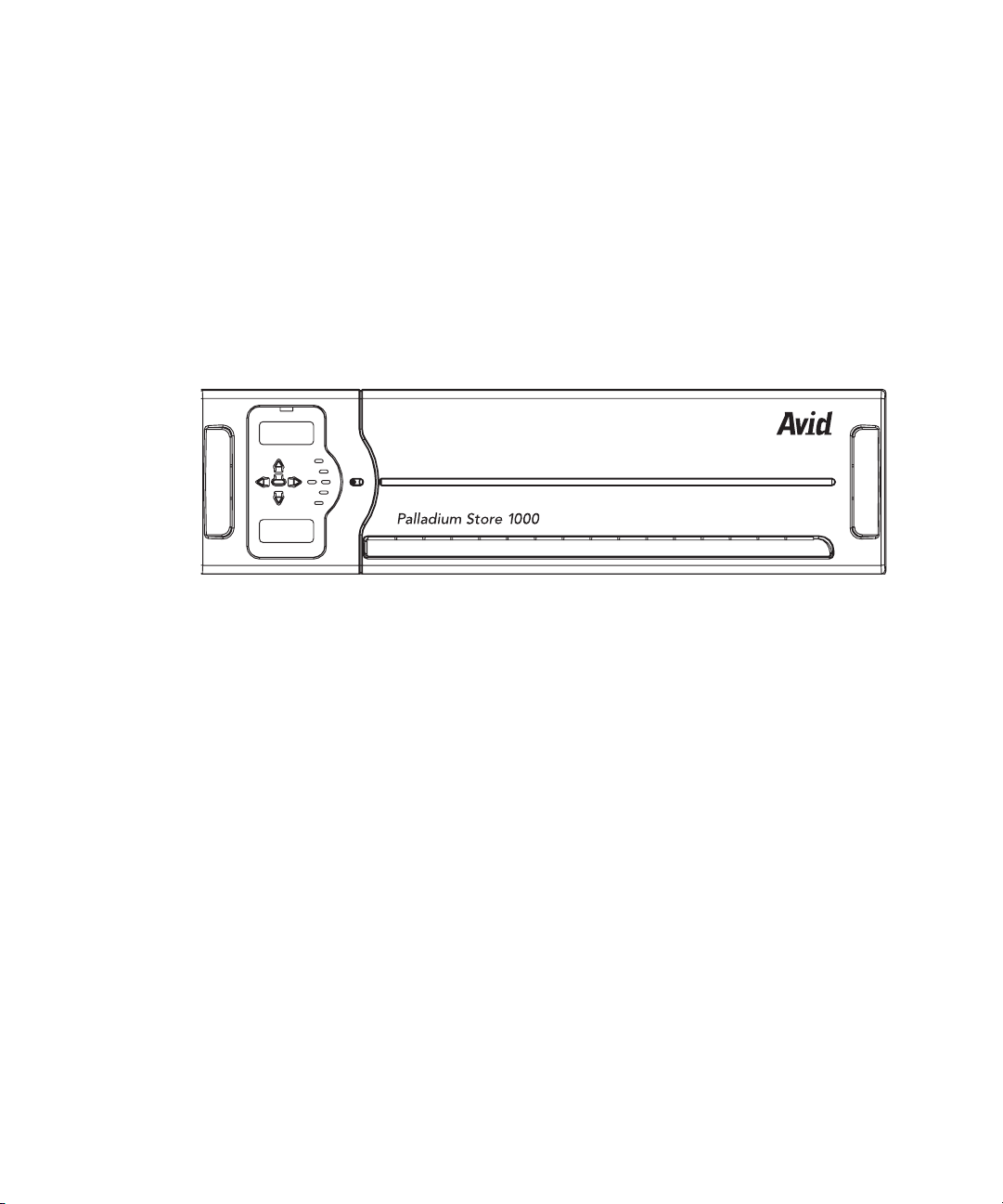
Palladium Store 1000
The Palladium Store 1000 storage system consists of one or more storage units. Each
Palladium Store 1000 chassis contains dual RAID controllers and 10 disks in two redundant
4+1 sets.
In case of a single disk failure in either or both of the disk sets, the system continues to
operate normally at full performance. After replacing the faulty disk, the system can
reconstruct the data from parity while operating at full performance.
Palladium Store 1000 - Front Bezel
MSS Networked Storage System Features
Each controller provides a separate data path to the server nodes. In case of a component
failure, the system will continue to operate normally. Hardware replacement of the failed
component can occur without service interruption.
MSS Networked Storage System Features
File System Redundancy
The MSS Networked Storage System is able to sustain a failure in any file system control
component without performance degradation, video loss, or jitter. The redundant
MediaStream Networked Storage File System control path consists of the following three
components:
• Two redundant FSCs that are independent from each other in software and hardware,
and which mirror the FSC File System in real-time.
29
Page 30

Chapter 1 Introduction
• Two redundant VLAN Ethernet switches, which are independent of each other in
functionality. These switches provide isolated connections between the video server
nodes and the two FSCs. The VLAN topology design prevents network loop conditions
that could lead to unacceptably long network time-out scenarios during an Ethernet
LAN connection failure.
• Two redundant Ethernet control connections on the server node connected to the two
VLAN switches.
During normal operation, one of the FSCs acts as the Primary Controller, while the other
acts as the Hot-Standby Secondary Controller. The Primary Controller controls the content
mirroring process of the Hot-Standby Secondary Controller; however, all MediaStream 8000
server nodes communicate directly with both the Primary and Secondary Controllers even
during normal operation and treat both FSCs equally. All File System requests issue twice,
one request per FSC, allowing for a transparent fail-over if one of the Controllers does not
respond.
Multiple Watch dog software modules distributed in the FSCs and the server nodes
constantly monitor the File System components and Ethernet connectivity. These software
modules ultimately make the decision if and when to switch the Secondary Controller to
become the Primary Controller. At that point the original Primary Controller is off-line and
can be serviced. Once the old Primary Controller comes back on line, it will automatically
become the Secondary Controller and will slave itself to the Primary Controller for content
mirroring and other housekeeping tasks.
Video Data Path Redundancy
The system is able to sustain a failure in one of the Fibre Channel data paths without
performance degradation, video loss, or jitter. The redundant data paths consist of the
following components:
• Dual Fibre Channel ports on the Fibre Channel card of the server node. These ports are
independent of each other in hardware and software.
• Dual RAID controllers per array. Both controllers are independent of each other in
hardware and software. Both FSCs have access to all of the storage at full bandwidth.
• Required Fibre Channel switches are always installed in redundant pairs.
• During normal operation, only one data path is used to read/write the data from/to the
storage system. If a failure in the data path occurs, the server node software detects this
failure in real-time and switches transparently to the other redundant data path. Since all
components are designed to deliver data at or above full bandwidth, there is no
performance degradation. The real-time fail-over design prevents video outages at the
decoder, as well as data overflow scenarios on the encoder system.
30
Page 31

MSS Networked Storage System Configuration
MSS Networked Storage System Configuration
All MediaStream Networked Storage Systems require redundant FSCs roller and redundant
VLAN switches for data control and redundant Fibre Channel switches for connection to the
array(s).
MediaStream Redundant System
File System
Controllers
VLAN
Switches
Isolated
Ethernet
Network
Fan
MSS 8000
Server Node
M
EDIASTREAMSERVER
Temperature Power Supply
M
EDIASTREAMSERVER
Fan
Temperature Power Supply
Fibre Channel
Switches
Storage
Subsystem
ALLADIUM
TM
S
TORE
1000
Adding Video Server Nodes and Channels
In most cases, adding additional video server nodes and channels to a system means that the
bandwidth requirement increases. Operators need to properly calculate if sufficient
bandwidth exists to support the increased channel count. This calculation can vary
significantly because it depends on how the system is used and operated in a given facility.
See for Appendix A for bandwidth calculation tables.
Adding additional channels to a server node is a straightforward process. Only the server
node that receives the channel upgrade needs to be shut down for the hardware and
configuration upgrade. Everything else will continue to operate normally.
P
ALLADIUM
TM
S
TORE
1000P
31
Page 32

Chapter 1 Introduction
Adding a server node involves hot-plugging the unit into the Ethernet VLAN topology to
provide file system connectivity and to connect the dual Fibre Channel interface into the
Palladium Store 1000 storage system. The Ethernet and Fibre Channel topology is factory
pre-configured to accommodate run-time configuration changes.
Adding Arrays to the System
Once the additional storage has been physically added, the operator needs to run File System
utilities to add the additional storage to the File System. For more information contact Avid
MediaStream Support.
The MSi Host PC
The system is administered via a host PC. The PC runs an application called MediaStream
Interface (MSi) that allows support personnel to playout, record, and run diagnostics on the
system components. Communication between the Host PC and the system components is via
redundant Ethernet connections to the dual VLAN switches. Depending on the
configuration, a storage cluster may have either one or two MSi PCs. Where there are two
MSi PCs, both have full access to all server nodes and both FSCs. Serial communication to
server nodes is provided by a Lantronix Ethernet-to-serial interface that integrated into each
server node chassis. This connection allows full access to the boot-up sequence of each
server node.
32
Page 33

MediaStream Interface (MSi)
MSI Screen Display
MSS Networked Storage System Configuration
y
The MediaStream Interface (MSi) is a Graphical User Interface (GUI) application used for
administering the MediaStream Server. The MSi provides support personnel a means of
playing, recording, rebooting, installing new software, and performing other maintenance
activities on the server node. While the MSi is capable of performing many activities
associated with playing and recording media clips, it is meant to be used as a support and
diagnostic tool.
33
Page 34

Chapter 1 Introduction
Simple Network Management Protocol (SNMP)
The MSS Networked Storage System includes status monitoring with Simple Network
Management Protocol (SNMP). The MSi’s System Status window presents SNMP data in
an easy to monitor graphic interface.
MediaStream System Status Window
34
The data is updated automatically at regular intervals (about two minutes). A trouble
condition, reported in any of the server node’s key operating modules (disk drives, array,
power supply, or cooling fans), updates the System Status display and changes the button
alert color to red. Click the System Status button to see a graphic representation of the server
node, FSCs, and arrays. A failed component is highlighted in red in the System Components
pane.
Page 35

Chapter 2
System Components
Although a MSS Networked Storage System may vary in scale and size, all systems share
certain components. This chapter examines the components that comprise a MSS Networked
Storage System:
• MediaStream 8000 server nodes
• File System Controllers
• Palladium Store 1000 Storage systems
• VLAN switches
• Fibre Channel switches
•MSi PC
• ConnectPlus 1000 NS Gateway PC
MSS 8000 Server Nodes
The MSS 8000 server node dseign uses VME 64-bit bus architecture (bus) and provides
high-speed communication between boards with a throughput of 400 Mbps. Direct
processing power is distributed among the cards plugged into the back plane.
The server interfaces with the station’s automation system using the RS-422 port with Video
Disk Control Protocol (VDCP) as defined in the Avid MediaStream VDCP documentation
and Ethernet LAN controls. Video content is sent in specified formats to the station’s routing
system.
Page 36

Chapter 2 System Components
Avid MediaStream Server 8000
Temperature Power Fans
After removing the server’s front panel, you can access the redundant hot-swappable power
supplies and view the three LED indicators for temperature, power supply, and fan status.
You can remove the cover that encloses the CPU I/O board (provides LAN, SCSI and
RS-232 connections to the CPU) and the Boot Drive. Mounted on the right side of the unit in
a pullout tray is the Lantronix Ethernet-to-Serial Interface that provides Console port access
via Telnet.
LEDs
36
Avid MediaStream Server 8000 - Front with Bezel Removed
LEDs
Temp. Power Fa n
supply
Redundant
power supplies
Lantronix
module
CPU-IO board
and boot drive
Page 37

Avid MediaStream Server 8000 - Rear
LAN
connections
Slots 1
through 10
System Controller
Fan trays
Encoder
Power
In the rear panel, VME slot 1 (bottom rear slot) contains the System Controller (CPU)/Fibre
Channel board that provides system control and data transfer to the Palladium Store 1000.
Slots 2 through 10 (numbering from bottom to top) contain decoder and encoder boards. Up
to 16 input/output channels can be supported using a combination of single- and
dual-channel boards. The left side of the unit contains LAN connections and power
switches.
System Controller
The System Controller board regulates backplane traffic. It performs only a fraction of the
actual computing on the Server; other boards perform activities such as MPEG
compression/decompression. The System Controller Board regulates traffic by maintaining
the bit rates of real-time processes (play and record) at the expense of non-real-time
processes, such as administrative tasks. No encoder or decoder traffic actually passes
through the System Controller Board. Video Input/Output traffic passes directly across the
VME Bus to its destination.
Dual decoders
System
controller/CPU/
Fiber Channel
(VME slot 1)
37
Page 38

Chapter 2 System Components
System Controller Board (CPU)
The MSS 8000 Boot Disk Drive mounts above the CPU-IO board and connects to it via a
SCSI connection.
MSS 8000 Boot Disk Drive
CPU I/O board
connects to
VME backplane
Encoders
System encoders are responsible for coding video for storage on disk. Base band ITU 601
video enters the System via a Serial Digital Interface (SDI) port on the encoder board. A
601 signal has a bandwidth of 270 Mbps, far too high for storage on a storage array. The
encoder applies MPEG video compression to the signal, which reduces the signal to between
6 Mbps and 50 Mbps.
38
Boot disk
tray
Page 39

System Controller
After the signal is compressed it is passed through the encoder to the VME back plane and
through Fibre Channel Adapter (FCA) to the external storage array. Encoders do not have
circuitry for playing out video signals. Signals must first be recorded to disk. Playback and
preview is accomplished by playing disk-based segments through a decoder card.
Encoder cards cannot accept analog signals. These signals must be converted to ITU 601 via
an analog to digital converter. The Revision 3 Encoder supports encoding for up to 8
channels of embedded audio.
AES-EBU audio is connected through an audio input module, which is bridged to the
encoder with a custom cable. Encoders are controlled by automation systems via RS-422,
which guarantees frame accuracy in recording.
Encoder Board
Serial ASerial B
Note: Unlabled items are not used.
Audio B
SDI IN A
Audio ASDI In B
Decoder boards are required to playback signals from the array to air. Decoders output
embedded AES/EBU audio with SDI, separate AES-EBU and analog audio (via adapter
panel) and Composite NTSC or PAL analog video. Software must be configured for
embedded audio on or off. Video connections are via BNC while audio connections are
ported via a special cable to a breakout panel. A loop-through Genlock port and an RS-422
control port are included as well.
The board designs employ new audio connections and new automation connections.
Connecting cables ship with each board. There are different cable connections for the four,
six, and eight channel audio versions of the boards.
The Audio cable part numbers are as follows:
• PN: 51010004 Cable audio 4 channel
• PN: 51010005 Cable audio 6 channel “Y” (Decoder)
• PN: 51013529 Cable audio 8 channel “Y” (Decoder)
The SD (Standard Definition) board comes in Dual and Single configuration. The Dual
Decoder board provides two channels of playout on a single card. Each channel has a
composite video output and an SDI SMPTE 259M output. The connections for Dual and
Single Decoder boards are the same, but the video, audio and control connections for the B
ports are not active and are not labeled on the Single boards. The board has support for four,
six, or eight channels of 16- and 20-bit audio which can be used for Dolby E or Dolby
39
Page 40

Chapter 2 System Components
Digital pass through. The board also features jog, shuttle, and Pinnacle’s patented CleanCut
MPEG decoding at bit rates up to 50 Mbps per channel. The following figure shows the
connections for the Dual SD Decoder board. The single version of the board has the same
connections, but the B Port connections are not active.
Dual Channel SD Decoder
GenlockSerial B Serial A Loop SDI B SDI AAnalog B Analog AAudio B Audio A
Genlock LED
Green: Genlock Available
Orange: Genlock Unavailable
Dec 1
Display alternates
between port addresses
DO NOT USE
n
n
The latest Avid I/O board is an all-in-one board with 8-channel audio that can be converted
into either a dual channel SD/HD Decoder, HD Input, or MPEG Input/Output board.
The HD (High Definition) decoder board provides SMPTE 292M output with a downconverted SD SMPTE 259M output channel. The board comes in dual- or single-channel
configuration and supports four or six channels of audio, using the same audio standard as
for the SD board. The board also supports jog, shuttle, and Avid MediaStream Systems’
patented CleanCut MPEG decoding at bit rates up to 50 Mbps for each channel.
Attach a 75-Ω terminator to the HD outputs when not in use.
Dual Channel HD Decoder
Dec 1
GenlockSerial B Serial A Loop HD B SDI B HD A SDI A
Genlock LED
Green: Genlock Available
Orange: Genlock Unavailable
Audio B Audio A
Display alternates
between port addresses
DO NOT USE
MPEG I/O Board
40
Serial ASerial B SD OUT A ASI I/O ASD OUT B ASI I/O B
Genlock Loop
Note: Unlabeld items are note used. Display shows port
addresses
Page 41

File System Controller
One of the factors in configuring an HD system is the bandwidth limitation. At 50Mbps, a
dual channel HD Decoder board and an HD Input board will occupy up to 200 Mbps of
bandwidth at maximum load (worse case).
HD Dual Channel Decoder
n
Channel 1 (Port A)
Channel 2 (Port B)
HD Input Board
Single Input
Tot al
The MediaStream HD Solution requires an external HD Encoder that can provide an ASI
signal to the MPEG Input card.
50 Mb + 25 Mb (Cueing) = 75 Mb
50 Mb + 25 Mb (Cueing) = 75 Mb
50 Mb = 50 Mb
File System Controller
n
The following figure shows the FSC 80 and FSC 200 models. If you have the Super Micro or
the IBM 335 models, see Appendix D.
File System Controller — Front
FSC 40
= 200 Mb
FSC 80
FSC 100
41
Page 42

Chapter 2 System Components
The MSS Networked Storage System design employs redundant Windows 2000 PCs to
operate as external File System Controllers (FSCs). Regardless of the size of a server cluster,
the system will always use only two FSCs. These controllers manage the content database
that is accessed by all server nodes for content playout. FSCs occupy one rack unit each.
The Power button enables you to safely shut down the Windows OS component of the unit
for servicing without requiring access to a Windows 2000 interface.
w
Powering down a FSC without verifying current system status could bring the system
off-air.
The rear of the unit provides monitor/keyboard/mouse connections and Ethernet
and VLAN connections.
File System Controller — Rear
FSC 40
FSC 80
FSC 100
Palladium Store 1000
Each MSS Networked Storage System cluster contains one or more arrays. Each array
storage unit consists of dual redundant Controllers. The array chassis contains 10 drives in
two banks of 4 plus 1 configured disks.
42
Page 43

Avid Palladium Store 1000
PS 1000 Controller Status Display
Panel navigation
buttons
ChA address
Palladium Store 1000
Controller A display
Controller status
Power supplies
silence
enter
ChB address
Fans status
Drive status
Temperature
Controller B display
The array storage chassis provides a display panel allowing monitoring of the chassis and
individual drives
The LED indicators on the front panel are as follows:
• Address indicator for Channel A and Channel B controllers
• Temperature indicator
• Disk status indicator
• Fan status indicator
• Power indicator
• Controller status indicator
43
Page 44

Chapter 2 System Components
VLAN Switches
Each MSS Networked Storage System cluster employs two Hewlett-Packard Pro Curve
VLAN 24 port switches.
Hewlett-Packard Pro Curve 2524 Switch
The left side of the switch contains an RS-232 console port for setup and
configuration of the switch, and indicators for switch status and activity.
HP Pro Cure 2524 Switch Indicators
44
The following table describes the VLAN switch control panel display.
VLAN Switch Indicators
LED Meaning Significance
Power (green) On. The VLAN is powered up OK
Off. No power Fix power supply
Fault (orange) Off. Normal OK
Blinking. Fault detected Look for component LED
blinking in unison
On. Goes out after self-test. If it remains on,
self test failed
Fatal hardware failure. Call tech
support
Page 45

VLAN Switch Indicators (Continued)
LED Meaning Significance
Self Test (green) Off. Normal during operation OK
On. Self-test in progress OK
Blinking. Component failure Look for component LED
blinking in unison
Fibre Channel Switches
Mode Select
(three green LEDs)
Fan Status (green) On. Normal Fans work
Port Activity LAN port with matching number is sending
Act. Port LEDs set to display network
activity
FDx. LEDs lit for ports in full duplex mode A display option
Max. LEDs lit for ports operating at full link
speed
!. Port LEDs display network events that
could require operator attention, such as
CRC errors and network collisions
Blinking. Failure Fan needs replacement
or receiving
Fibre Channel Switches
Your system will include two independent and redundant Fibre Channel switches.
Depending on the size of the cluster, different Fibre Channel switches will be used. The
Fibre Channel switches provide the link between the server nodes and the Palladium Store
1000 storage arrays. Each switch provides an independent path to each server node and to
each array. Up to 16 server nodes and one-to-eight storage arrays are connected to the
switches. Should any path fail on one switch, communication will continue via the
redundant path on the second switch.
A display option
A display option
A display option
LAN port works
Avid supports an 8-port and a 16-port fibre channel switch.
Avid supports an 8-port and a 16-port fibre channel switch.
FCS - Brocade SilkWorm 3250
45
Page 46

Chapter 2 System Components
FCS - Brocade SilkWorm 3850
Status indicators vary between models.
Gadzoox 2000
Gadzoox 3000 HA
Status indicators vary between models.
MSi PC
Each MSS Networked Storage System cluster has either one or two MSi PCs, depending on
the option purchased. Although a system cluster can function without an operational MSi
PC, the MSi PC is valuable in that it enables you to monitor all system components. Systems
with a second MSi PC have redundant system-monitoring capability.
MSi 2000 - Front Panel
46
Page 47

MSi PC
The rear of the unit provides two LAN ports for system communications. There is also a
connector for the internal modem and one for an optional analog phone, which you can use
when the modem is not in use. Other connectors include a serial, VGA, and USB port. If
your MSi PC has the optional Fibre Channel card installed, there is a Fibre Channel port.
MSi 2000 - Rear Panel
Mouse
Keyboard
RS-232
connector
VGA port
LAN 2
Unused
USB
modem
LAN 1
The Avid MediaStream Interface (MSi) application provides a means of playing, recording,
rebooting, installing new software, and performing other maintenance activities on the
server.
Main MSi Window
47
Page 48

Chapter 2 System Components
The Host PC communicates with the server components through a LAN connection.
A Lantronix Ethernet-to-serial interface, which is integrated into each server node, provides
serial communication to servers, allowing full access to the boot sequence.
Simple Network Management Protocol (SNMP)
The Simple Network Management Protocol is a set of networking protocols designed to
provide diagnostic data over networks. The MediaStream 8000 Server employs SNMP to
provide a user with easily accessible and regularly updated diagnostic data. Data is fed to the
MSi and is displayed graphically in the System Status window of the MSi application.
System Status Window
48
The data is updated automatically at regular intervals (about two minutes) and sent to the
MSi. If a trouble condition is reported in any of the server’s key operating modules (array,
power supply, or cooling fan, the System Status button changes color from green (good) to
red (bad). Clicking the System Status button shows a graphic representation of the system
components. The MSS 8000 and the Palladium Store 1000 are shown to the left of the main
window. System components that fail are highlighted in the main window.
Page 49

ConnectPlus 1000 NS Gateway PC
ConnectPlus 1000 Networked Storage (option) is a gateway that provides access to archive
storage and to content distribution with other MediaStream Servers. Data transfer is
accomplished via Pinnacle’s implementation of standard FTP (File Transfer Protocol),
providing for easy integration with automation and archive systems.
ConnectPlus 1000 NS Gateway PC
n
When configuring one or more Gateway PCs into a networked storage system, special
consideration must be given to bandwidth load of the entire system. Each configured
gateway must be considered a server node with adequate bandwidth allocated for its use.
Failure to consider gateway impact on system bandwidth can have serious system-wide
performance implications. See Appendix A for more information on bandwidth calculations.
Connect Plus 1000 - Front Panel
49
Page 50

Chapter 2 System Components
50
Page 51

Chapter 3
VLAN Topology
This chapter introduces the VLAN topology used in the MSS Networked Storage System.
Topics covered include:
• Hosts table
• Ethernet topology diagrams
• IP addressing scheme
VLAN Topology
The Networked Storage System uses redundant VLAN Ethernet switches to provide fast and
safe fail-over in the event of a break in network connectivity. Each switch provides isolated
connections between the server nodes and the two FSCs. The VLAN topology design
prevents network loop conditions that could lead to unacceptably long network time-out
scenarios during a LAN failure.
To ensure system redundancy, installation must conform explicitly to system design
parameters. Each switch must have the current firmware and the correct switchconfiguration files installed. With VLAN, a different network is assigned for each server
node providing isolated connection paths between the server nodes and the FSCs.
Page 52

Chapter 3 VLAN Topology
Hosts File
The hosts file provides name resolution for all devices within the cluster. The complete hosts
file on the FSCs and MSi PC is quite large and contains all names and addresses for all 16
possible clusters. Each server node contains a hosts file for a given cluster. An abbreviated
version of this file (with headings separating devices) follows. Sequential addresses have
been skipped, and any entry ending with xx… shows a continued sequence to the next entry.
Aliases
Some device hostnames have been provided with aliases to simplify the connection of
devices via Telnet. Connections can be established by using the hostname, LAN address, or
any provided alias.
Host Table for Cluster 1
Host Name LAN Address Aliases
MSS 8000 (LAN)
52
mss0101 10.64.1.3
mss0102 10.64.2.3
mss01xx … 10.64.xx.3 …
mss0116 10.64.16.3
MSS 8000 (Console)
con0101 10.64.1.4
con0102 10.64.2.4
con01xx … 10.64.xx.4 …
con0116 10.64.16.4
FSC1
fsc0101-1 10.64.1.1 fsc0101A fsc0101
fsc0101B 10.64.21.1
Page 53

Hosts File
Host Table for Cluster 1 (Continued)
Host Name LAN Address Aliases
fsc0101-2 10.64.2.1
fsc0101-xx … 10.64.xx.1 …
fsc0101-16 10.64.16.1
fsc0101-22 10.64.22.1
FSC 2
fsc0102A 10.64.21.2 fsc0102
fsc0102-1 10.64.1.2 fsc0102B
fsc0102-2 10.64.2.2
fsc0102-xx … 10.64.xx.2 .
fsc0102-16 10.64.16.2
fsc0102-22 10.64.22.2
MSI 1
msi0101-1 10.64.1.5 msi0101A
msi0101-17 10.64.17.5 msi0101B
msi0101-2 10.64.2.5
msi0101-xx … 10.64.xx.5 …
msi0101-16 10.64.16.5
MSI 2
msi0102-1 10.64.1.6 msi0102A
msi0102-17 10.64.17.6 msi0102B
msi0102-2 10.64.2.6
msi0102-xx … 10.64.xx.6 …
53
Page 54

Chapter 3 VLAN Topology
Host Table for Cluster 1 (Continued)
Host Name LAN Address Aliases
msi0102-16 10.64.16.6
Gateway
gwy0101-1 10.64.1.11
gwy0101-2 10.64.2.11
gwy0101-3 10.64.3.11...
gwy0101-16 10.64.16.11
gwy0101-21 10.64.21.11
gwy0102-1 10.64.1.12
gwy0102-2 10.64.2.12...
FC Switch
fcw0101 10.64.21.36
fcw0102 10.65.17.37
VLAN Topology Diagram
The following diagram shows a logical Ethernet connections for the 24-port switch. Your
installed system ships with color-coded labels and cables to make both wiring and tracing
connections easier. This diagram will help you isolate network paths when servicing or
troubleshooting the system.
All tagged connections are VLAN logical connections while untagged connections are fixed
LAN addresses. For tagged VLAN connections, the sequence of addresses has been
abbreviated to simplify the diagram. In addition, only the last two octet groups of the address
are provided. The complete address includes the 10.xx prefix that designates the cluster.
n
54
The port layout of the 24-port switch is not physically the same as shown here. Make your
connections based on the port numbers, not their apparent positions in this diagram.
Page 55

VLAN Topology
)deggatnu
)deggatnu(
(
losnoC 4.1
1010
N
A
S
L 3.1
SM
Ethernet topology of a Single MSS
Networked Storage Cluster
24 Port Switch
)degg
)deggatnu(
a
tnu
(
losnoC 4.2
2010
N
A
S
L 3.2
SM
)de
)d
gg
eggatnu(
at
nu
(
losno
30
NA
10SSM
L
C
3.3
4.3
)deg
)
d
g
eggatnu(
atn
u
(
losno
4
010SSM
NA
L
C
3.4
4.4
)
degg
)d
eggatnu(
a
tnu
(
50
losno
NA
10SSM
C
L
4.5
3.5
Hosts File
)d
egg
)d
egg
a
tnu
a
tnu(
(
601
losno
NA
0SSM
L
C
3
4
.
.
6
6
)de
)d
gg
eggatnu(
a
tnu
(
70
losn
N
10
o
A
S
L
C
3.7
4.7
SM
)deg
)d
g
e
a
gga
t
nu
t
(
nu(
losn
80
N
10
o
A
S
C
L
SM
4
3
.8
.8
GWY 1
(tagged)
.1.11
.2.11
.3.11
. .....
.16.11
.21.11
123456789101112
123456789101112
HP2524 A 21.34 HP2524 A 17.35
13 14 15 16 17 18 19 20 21 22 23 24
GWY 2
(tagged)
.1.12
)yawetaG( 1010
.2.12
.3.12
. .....
.16.12
.21.12
Y
WG
)deggatnu( 7.821
)ya
we
taG(
2010YWG
)d
eg
ga
t
nu
(
8
.
92
1
)d
eggatnu(
hct
iwS
63
.1
CFA
2
FSC 1
(tagged)
.1.1
.2.1
.3.1
. .....
.16.1
.17.1
13 14 15 16 17 18 19 20 21 22 23 24
21.0
)
d
5
.
eg
71
g
atn
u
(
LAN 2 LAN 1
MSI 1
(tagged)
.1.5
.2.5
.3.5
. .....
.16.5
.21.5
LAN 3 LAN 2
FSC0101
LAN 1
21.1
(untagged)
22.1
(untagged)
B
hct
1010ISM
i
w
S CF
71
6.
u(
n
deggat
)
)d
eggatnu(
73
.7
1
LAN 2LAN 1
2010
IS
M
21.2
(untagged)
LAN 2 LAN 3
FSC0102
LAN 1
22.2
(untagged)
MSI 2
(tagged)
.1.6
.2.6
.3.6
. .....
.16.6
.21.6
FSC 2
(tagged)
.1.2
.2.2
.3.2
. .....
.16.2
.17.2
Router A
(tagged)
.1.32
.2.32
.3.32
. .....
.16.32
.17.32
.21.32
Router A
Router B
(tagged)
.1.33
.2.33
.3.33
. .....
.16.33
.17.33
.21.33
Note:
Ports 9-16 available for
additional MSS-8000
Server Nodes
Router B
55
Page 56

Chapter 3 VLAN Topology
Networked Storage System I/P Addressing Scheme
IP Address Scheme Example
Network
Cluster
ID
The addressing scheme takes a 32-bit TCP/IP address and breaks it into logical units that can
be used to identify cluster, network IDs, and device IDs. The four-octet network address is
logically allocated to distinguish between clusters, VLAN networks, and device IDs. All
clusters are addressed as follows:
The first octet is always 10. The second octet designates cluster ID. Cluster 1 (the most
common) is 10.64.xxx.xxx. Addresses 64 to 79 are allocated for the first 16 clusters, with
clusters 17 through 32 using addresses 81 to 96. Clusters 33 to 48 use 64 through 79, but the
third octet (the network ID, described below) for VLANs in these clusters starts with 65
rather than 1.
ID
10.xxx.yyy.zzz
Device
ID
56
Cluster Addressing
Initial Cluster Addresses
Cluster 1
Cluster 2
Cluster 3
Cluster 4
Cluster 5
Cluster 6
Cluster 7
Cluster 8
Cluster 9
Cluster 10
10.64.1
10.65.1
10.66.1
10.67.1
10.68.1
10.69.1
10.70.1
10.71.1
10.72.1
10.73.1
Cluster 17
Cluster 18
Cluster 19
Cluster 20
Cluster 21
Cluster 22
Cluster 23
Cluster 24
Cluster 25
Cluster 26
10.81.1
10.82.1
10.83.1
10.84.1
10.85.1
10.86.1
10.87.1
10.88.1
10.89.1
10.90.1
Cluster 33
Cluster 34
Cluster 35
Cluster 36
Cluster 37
Cluster 38
Cluster 39
Cluster 40
Cluster 41
Cluster 42
10.64.65
10.65.65
10.66.65
10.67.65
10.68.65
10.69.65
10.70.65
10.71.65
10.72.65
10.73.65
Page 57

Networked Storage System I/P Addressing Scheme
Cluster Addressing (Continued)
Initial Cluster Addresses
Cluster 11
Cluster 12
Cluster 13
Cluster 14
Cluster 15
Cluster 16
10.74.1
10.75.1
10.76.1
10.77.1
10.78.1
10.79.1
Cluster 27
Cluster 28
Cluster 29
Cluster 30
Cluster 31
Cluster 32
10.91.1
10.92.1
10.93.1
10.94.1
10.95.1
10.96.1
Cluster 43
Cluster 44
Cluster 45
Cluster 46
Cluster 47
Cluster 48
10.74.65
10.75.65
10.76.65
10.77.65
10.78.65
10.79.65
The third octet grouping acts as a network ID, dividing a cluster into separate VLAN
networks, providing isolated communication paths for each server node. Sixteen separate
networks are allocated for server node communication with additional network paths
available for gateway, MSi PC, switch, and router traffic.
The fourth and final octet grouping acts as a device ID specifying the device type and/or
number in a storage cluster. The hosts file contains all addresses in all clusters with name
resolution for each device in a cluster.
The FSCs, MSi PCs, gateways, and routers employ VLAN Ethernet cards in addition to
standard Ethernet NICs to allow communication with devices across multiple networks
within a cluster.
Subnet Mask
The network uses the Class C subnet mask of 255.255.255.0, providing up to 256 individual
addresses per designated network ID.
Hosts Table and Addressing
Given the above parameters, the following devices are named and addressed in the hosts file
on systems components and integrated into the VLAN Switch:
• MSS 8000 server nodes and console ports
• File System Controller 1 and 2
•MSi PC 1 and 2
57
Page 58

Chapter 3 VLAN Topology
• Gateways 1 through 8
• Fibre Channel (FC) Switch A and B
•Router A and B
LAN Port Name And Address
Hostname = mss<xx><yy> where xx equals cluster number and yy equals server node
ID
e.g., mss0101 is Network 1 Server Node 1 of Cluster 1
LAN address = 10.<xx>.<yy>.3 where xx equals cluster ID and yy equals server node
ID
e.g., 10.64.1.3 for Network 1 Server Node 1 of Cluster 1
n
n
File System Controllers (FSCs)
The device ID (the last octet group) is always 3 for server nodes.
Console Address
Hostname = con<xx><yy> where xx equals cluster number and yy equals server node
ID
e.g., con0101 is Network 1 Console Port 1 of Cluster 1
LAN address = 10.<xx>.<yy>.4 where xx equals cluster ID and yy equals console port
ID
e.g., 10.64.1.4 for Network 1 Console Port 1 of Cluster 1
The device ID is always 4 for console ports.
There are two FSCs in each MSS Networked Storage System cluster. Each FSC has three
Network Interface Cards (NICs). The first is a VLAN connection to its primary switch. The
VLAN card is logically addressed (tagged) for communication with all configured networks
on the VLAN switch. This connection allows direct communication between the FSC and
each of the server nodes as well as the second FSC, MSi PCs, gateways and Fibre Channel
switches. The second is a direct connection to the redundant VLAN Switch. The third is a
direct crossover connection to the second FSC.
The convention for naming and addressing the three NICs is as follows:
58
Hostname
Hostname = fsc<xx><yy>-<z> where xx equals cluster number, yy equals FSC ID
(FSC A is “01” while FSC B is FSC “02”) and z is Network ID.
e.g., fsc0101-3 is FSC A of Cluster 1 on Network ID 3
Page 59

Networked Storage System I/P Addressing Scheme
LAN 1 Connection
LAN address = 10.<xx>.<22>.<z> where xx equals cluster ID and z is either “1” for
FSC A or “2” for FSC B.
e.g., 10.64.22.1 for FSC A on Cluster 1
n
n
MSi PCs
This is the crossover connection between the two FSCs.
LAN 2 Connection
LAN address = 10.<xx>.<21>.<z> where xx equals cluster ID, and z is either “1” for
FSC A or “2” for FSC B.
e.g., 10.64.21.2 for FSC B on Cluster 1
LAN 3 Connection
LAN address = 10.<xx>.<yy>.<z> where xx equals cluster ID, yy equals Network ID
and z is either “1” for FSC A or “2” for FSC B.
e.g., 10.64.3.1 is FSC A of Cluster 1 on Network ID 3
The VLAN card is configured for 17 logical addresses (from Network ID 1 to 17). It in effect
creates a “Virtual” Network Interface Card for each address. The hosts file for the VLAN
port on the FSC will include a hostname and LAN address for each of these.
A MSS Networked Storage System cluster will always have at least one MSi PC configured
but may have a second unit installed for redundant monitoring of the system. Each MSi PC
has one tagged VLAN NIC and one conventional Ethernet card installed. The VLAN
connection is for direct connection to the PCs primary VLAN switch while the Ethernet port
is for redundant connection to the secondary VLAN switch. The convention for naming and
addressing the two NICs is as follows:
n
Tagged VLAN Connection
Hostname = msi<xx><yy>-<z> where xx equals cluster number, yy equals MSi ID
(MSi 1 is designated “01” while MSi 2 is designated “02”) and z is network ID.
e.g., msi0101-1 is MSi 1 of Cluster 1 on Network ID 1
LAN address = 10.<xx>.<yy>.<z> where xx equals cluster ID and yy equals network
ID; and z is either “5” for MSi 1 or “6” for MSi 2.
e.g., 10.64.3.5 for Primary MSi on Network ID 3
The VLAN card is configured for 17 logical addresses (from Network ID 1 to 16 plus
Network ID 21).
59
Page 60

Chapter 3 VLAN Topology
Redundant Connection
Hostname = msi<xx><yy>-17 where xx equals cluster number, yy equals MSi ID (MSi
1 is designated “01” while MSi 2 is designated “02”)
e.g., msi0101-17 is MSi 1 of Cluster 1 Network ID 17
LAN address = 10.<xx>.17.<y> where xx equals cluster ID and y is either “5” for MSi
1, or “6” for MSi 2.
n
Gateways
n
In all cases the device address is always 5 for MSi 1 or 6 for MSi 2.
A MSS Networked Storage System cluster may have optional gateways installed. The
gateways allow for content sharing between clusters and/or legacy MediaStream Servers. Up
to eight gateways may be configured into a system although a system is usually configured
for one or two. Each gateway has a VLAN NIC with three tagged addresses as well as an
untagged Ethernet port. The untagged port is available for connection to external networks,
not to the system’s switches. Since the gateways are not mission-critical on-air components,
redundant connections are not needed, and each gateway is connected to only one of the
VLAN switches:
Tagged VLAN Connection
Hostname = gwy<xx><yy> where xx equals cluster number and yy equals gateway
number; gateways are numbered from 1 to 8.
e.g., GWY0101 = Gateway 1 in Cluster 1
LAN address = 10.<xx>.<yy>.<zz> where xx equals cluster ID, yy equals Network ID,
and zz equals device ID. Gateways are ID’d from 11 to 18.
e.g., 10.64.16.11 for Gateway 1 ID 11 on network ID 16
Each gateway has tagged VLAN addresses for network IDs 1 through 16 and 21. Gateway
device IDs will always be between 11 and 18 (11 for Gateway 1 and 18 for Gateway 8).
60
Gigabit Ethernet Connection
Hostname = gwy<xx><yy> where xx equals cluster number, yy equals gateway
number; gateways are numbered from 1 to 8.
e.g, GWY0101 = Gateway 1 in Cluster 1
LAN address = 10.<xx>.<yy>.<zz> where xx equals cluster ID, yy equals network ID,
and zz equals device ID
e.g., 10.64.128.11 for Gateway 1 in Cluster 1 on Network ID 128
Page 61

Fibre Channel Switches
A LAN connection is provided for each Fibre Channel switch to the VLAN switches to
provide access by the MSi PC for maintenance purposes. Each FC Switch is connected to
one of the VLAN switches. It is important to note that redundant connections are not
available, and monitoring will only be possible from MSi 1. These connections have been
provided as a convenience when servicing the switch.
Hostname = fc<xx><yy> where xx equals cluster number, yy equals FC switch
number. Switches are designated A or B.
e.g., FC0101 = FC Switch A in Cluster 1
LAN address = 10.<xx>.<yy>.<zz> where xx equals cluster ID yy equals network ID
and zz equals Device ID. Device ID is 36 for FC Switch A and 37 for FC Switch B.
e.g., 10.64.21.36 for FC Switch A in Cluster 1 on Network ID 6. and 10.65.17.37 for FC
Switch B on Cluster 1 Network ID 17
Networked Storage System I/P Addressing Scheme
n
Routers
FC Switch A can communicate with MSi PC 1 on Network ID 21 while FC Switch B is set to
Network ID 17 to allow communication with MSi PC 1 through its direct connection on
Network ID 17 with VLAN Switch 2.
A MSS Network Storage System cluster may be configured with optional routers to allow
communication to occur between the cluster devices and an internal LAN in the facility.
Each router is configured with a VLAN NIC to allow communication between configured
Network IDs and external devices. With redundant routers connected to each switch,
redundant communication paths are available to external networks The VLAN addresses are
configured as follows:
LAN address = 10.<xx>.<yy>.<z> where xx equals cluster ID, yy equals network ID
and z equals router device ID. This is 32 for Router A and 33 for Router B.
61
Page 62

Chapter 3 VLAN Topology
62
Page 63

Chapter 4
Preparation and Installation
This chapter describes the site preparation and installation process which includes the
following tasks:
• Site preparation checklist
• Receiving the Networked Storage System
• Installing system components into racks
About 8 weeks prior to installation, assign a site coordinator. The following table offers
guidelines for the site coordinator. For specific information, refer to the appropriate sections
in this chapter.
Site Preparation Time Table
Time
Frame Activity
8 weeks
prior to
installation
Based on the components you have ordered, determine the type of racks and
rack-mounting screws you will need and order them.
Determine what kind of racks you will need.
Select the location for the MSS 8000. Consider existing electrical outlets and
lighting, immovable objects, floor vents, etc.
Page 64

Chapter 4 Preparation and Installation
Site Preparation Time Table (Continued)
Time
Frame Activity
6 weeks
prior to
installation
Create a site layout plan.
Schedule with appropriate trades persons to ensure that the site is in compliance
with structural, power, interface, and environmental specifications.
Obtain external cables as necessary. Avid MediaStream provides cables to
connect Avid MediaStream server components. (Check with your Avid
MediaStream Sales Representative if you plan to attach multiple arrays.) You
need to provide external connections to station automation, video, and audio
devices. See Appendix B.
Follow these guidelines when preparing your site for the installation
• Allow enough space at the site to accommodate additional servers and arrays should
your requirements increase.
• Locate cables away from traffic paths to prevent accidents and equipment failures.
• Allow space for a monitor to connect to the analog output of each decoder.
• Consider space for your MSi PC (racked or adjacent).
• Consider space for other equipment, such as the automation station.
• For proper ventilation of the MSS 8000 component racks, and to ensure enough room to
perform periodic maintenance and servicing, install the MSS 8000 components a
minimum of 40 inches (1 m) (front and back) from walls or other items that might
obstruct airflow or the removal of modules.
Avid MediaStream Support recommends that the equipment racks be anchored at the ceiling
or floor or bolted to the wall. Ensure that the racks will be stable when all equipment is
loaded into the racks. The center of gravity in a fully loaded rack must be low enough to
keep the rack from being top heavy.
This section addresses floor load limits, vibration, and heat dissipation.
Floor Load Limit
The room that will house the MSS 8000 must be able to support the total weight of the
various components, as well as the localized weight at each level of your rack or cabinet.
To estimate floor strength requirements, consider the following items:
1. Total weight of the MSS 8000 components and any associated equipment.
2. Total weight of furniture such as desks, chairs, tables, racks, etc.
64
Page 65

3. Total approximate weight of the operating personnel.
4. Weight of the moving equipment (such as forklifts and transport dollies).
Ensure that all floors, stairs, and elevators to be used when the server is moved to its
destination can support the weight of the server and moving equipment.
Refer any questions regarding the adequacy of floor construction to a qualified structural
engineer for evaluation.
Vibration
Vibration, when severe, can cause a slow degradation of mechanical parts and connections
and data errors in disk drives. If you suspect that vibration might be a problem, contact Avid
MediaStream Technical Support for advice and recommendations.
Heat Dissipation
Consider the heat dissipation by the MSS 8000 components as well as other equipment at
the site, individuals working at the site, and lighting to determine whether the existing air
conditioning system is adequate, or if an upgrade is necessary.
When estimating heat dissipation, consider the addition of Networked Storage components,
should your requirements increase.
Environmental Considerations
n
The cooling air for the server flows in the front and out the left side of the unit. Make sure
that there is enough space between the left side of the server and other equipment in
neighboring racks so warm air can escape.
Environmental Considerations
This section covers ideal operating temperature, electromagnetic interference, and
electrostatic discharge.
Temperature and Humidity
To ensure that airflow is not impeded, and to ensure adequate space to perform periodic
maintenance and servicing, do not place racks closer than one meter to walls or obstructions
in the front and back.
For reliable operation, maintain room temperature between 20 and 25 degrees Celsius (68
and 77 degrees Fahrenheit), and relative humidity between 30 and 50
65
Page 66

Chapter 4 Preparation and Installation
Electromagnetic Interference
The MSS Networked Storage System is designed to reduce susceptibility to radiated and
conducted interference. The MSS Networked Storage System conforms to the
electromagnetic susceptibility (EMC) standards. Excessive electromagnetic interference can
cause a variety of problems. Avid MediaStream Support can advise you about the most
common causes of electromagnetic interference.
Electrostatic Discharge
Static electricity at the MSS Networked Storage System location should be within the
normal range (lower than 15 KVs). Carpeting or low humidity will facilitate the generation
of static electricity, especially in dry and cold climates.
To reduce static electricity, install grounded mats in front of the MSS Networked Storage
System. Avid MediaStream Support recommends using a heat evaporating humidifier (and
strongly recommends against using a cold water atomizer humidifier).
Anti-static spray is not recommended because it can enter the intake filters and coat the
circuitry. If you must use a spray, apply it while the MSS Networked Storage System
components are turned off.
66
Use the following checklist to schedule activities and to monitor the progress of the site
preparation process.
Site Preparation Checklis t
Date
Activity
Have phone lines and modem (data) lines been installed? A direct analog line (not
a PBX connection) is required to receive Avid MediaStream Support.
Has the possible need for lifting/moving equipment been addressed?
Will the flooring and the installation site itself support the weight of the racks,
moving equipment, and personnel? Are doorways and pathways wide enough to
accommodate the shipping crate and boxes?
Has the site layout plan been completed?
Does the layout show the location for all proposed equipment?
Completed
Page 67

Receiving Server Components
Site Preparation Checklis (Continued)t
Date
Activity
Have the equipment racks been installed? Are they anchored to the floor and
ceiling or bolted to the wall? Have you ensured that the racks will be stable
enough to support all installed equipment?
Is sufficient space provided in front of and behind the racks for operation and
service?
Is space provided for manuals and supplies?
Is proper and adequate power available at the site for the systems components?
Are all appropriate uninterruptible power supply (UPS) units on line?
Have tests been conducted to determine the voltage fluctuations throughout the
day?
Do you have enough power receptacles for any supplemental equipment, such as
a tape backup?
Completed
Has interface cabling been properly routed to the installation site?
Has the installation site been checked for minimum and maximum temperature
and relative humidity range?
Has any problem with excessive vibration, electromagnetic interference, and
electrostatic discharge been resolved?
Receiving Server Components
The server, MSi PC and its monitor, File System Controllers, switches, the array(s) and
other components are packaged in separate containers. If your shipment includes the
optional Rack Mounting Kit for the MSi PC, you will receive additional boxes that contain
the rack-mounting accessories.
When the shipment arrives, check each container against the carrier’s shipping documents.
Inspect the exterior of each container immediately for mishandling or damage during transit.
If any of the containers are damaged, request the carrier’s agent be present when the
container is opened.
67
Page 68

Chapter 4 Preparation and Installation
n
w
n
Do not throw anything away until you have found and unpacked all of the components.
To protect the components, leave them in their packaging until you are ready to install them.
Keep the shipping materials. If you have to repackage any of the components, you will need
the original shipping materials.
The MSS Networked Storage System components are fragile. Some components can be
damaged even when carefully handled. Move components in their original packaging.
The components are packed in containers that can weigh more than 120 pounds (55
kg). Exercise care when moving them to avoid injury.
The server ships in a wooden crate. Ensure that doorways and pathways are wide enough to
allow passage. The following table shows the dimensions of the boxes and crates.
Chassis Shipping Box Dimension
Component Length Width Height
File System Controller: 23.5 in (59.7 cm) 34.0 in (86.4 cm) 8.0 in (20.3 cm)
MSi Monitor 19.5 in (49.5 cm) 20.5 in (52.1 cm) 7.25 in (18.4 cm)
MSi Computer 16.75 in (42.5 cm) 19.25 in (48.9 cm) 18.5 in (47 cm)
n
w
68
MSS8000si Serve 35.0 in (88.9 cm) 36.0 in (91.4 cm) 19.0 in (68.6 cm)
Fibre Channel Switch 20.0 in (50.8 cm) 21.75 in (55.2 cm) 9.5 in (24.1 cm)
Palladium Store 1000 Chassis 27.5 in (69.9 cm) 24.75 in (62.9 cm) 14.5 in (36.8 cm)
Palladium Store 1000 Drives (2 boxes) 20.5 in (52.1 cm) 14.5 in (36.8 cm) 11.5 in (29.2 cm)
Use an elevator to move containers. Stairs may result in excess vibration. Leave components
in the packaging until you are ready to install them.
Never touch any exposed electrical connectors on the components as they can be
damaged by electrostatic discharge (ESD). Never drop or sharply bump the array(s).
This can cause immediate or delayed failure of the disk drives, permanent data loss, or
intermittent operation.
A server ships in one crate and several boxes. Carefully check all compartments of each box.
Page 69

To unpack the crate:
1. Remove the wire clips that surround the top of the crate and remove the lid.
2. Remove the front panel, rack ears, cords, and accessories from the pockets around the
inside of the crate. Some small items may be in packaging material.
3. On the outside of the crate, unfasten the latches that secure the sides of the crate to its
bottom. To unfasten the latches, flip the lever of the latch up, and then turn the lever
counter-clockwise.
4. Lift the crate up and over the main server chassis, placing the crate out of the way.
5. Remove all packing foam surrounding the server.
Inspecting the Contents of the Shipment
As you unpack the shipment, account for and inspect all the components:
• Check each container against the packing list to ensure all shipping containers were
received.
• Check all packing materials and containers for the missing components. Small
components, such as adapters and short cables, can remain undetected in the packing
materials.
• Check the packing foam for damage that indicates rough handling during transit.
Receiving Server Components
• Look for broken controls and connectors, dented corners, scratches, bent panels, and
loose components.
• Check the exterior of the components for the following signs of shipping damage:
- Look at the top and sides for dents, warping, or scratches.
- Check the connector panels for signs of damage (bent or broken connectors,
scratches, and so forth).
If you have any problems with the shipment, refer to the claims procedure guidelines.
Claims Procedure Guidelines
If you found any damage, follow these claims procedures.
n
Some damage may be repaired by replacing the part. In the case of extensive damage, you
need to return all of the components to Avid MediaStream Support. Contact your Avid
MediaStream representative immediately.
Notify your Avid MediaStream representative if the shipment is incomplete or if any
shipment contents are damaged. If damage occurred in transit, also notify the carrier.
69
Page 70

Chapter 4 Preparation and Installation
n
Server Repacking Guidelines
Technical Assistance
Avid will arrange for repair or replacement without waiting for settlement of claims against
the carrier. If damage occurred during shipping, retain the packing container and packaging
materials for inspection.
To repackage any of the server components for shipment, reverse the appropriate
unpacking procedures.
Use the original packing material to repackage the components for shipment. If the packing
material is not available, contact your local Avid MediaStream Support Sales and Support
Office in the U.S., or contact your Avid MediaStream Support authorized dealer outside the
U.S. regarding shipment.
If your server is still under warranty:
• Before you call Avid MediaStream Support, record the model and serial numbers of
your server. You need to remove the front panel to locate these numbers.
• If you opt to have a replacement part shipped to you, retain the packaging materials for
the return shipment of the failed assembly, and follow the instructions on the Return
Authorization Form that will be included with the part.
• Customers outside the USA should contact their local dealer or Avid MediaStream
Systems representative for assistance in diagnosing a problem and identifying a possible
failed assembly.
After the warranty expires, you can purchase a Avid MediaStream Support service contract.
Please contact your Avid MediaStream Support Sales Representative for more information.
Visit the Avid MediaStream Support Web site for more information about Avid
MediaStream Support: www.avid.com.
Installing the MSS Networked Storage System
A rack unit (RU) is the measurement rack manufacturers use to measure the height of
equipment mounted in the rack. A rack unit is 4.45 centimeters (1.75 inches). Some rack
manufacturers provide an additional hole or other symbol to mark the rack unit, as shown in
the following figure.
w
70
Because of the weight of the some of the units, installing the MediaStream server and
Palladium Store 1000 requires at least two people. A third person may be needed to
stabilize and guide the chassis while two others lift and slide the module onto the rack
rails
Page 71

Installing the MSS Networked Storage System
n
Rack mounting screws vary. Avid MediaStream does not provide hardware such as mounting
screws. See your rack manufacturer for these items.
Rack Unit
Use the information in the following table to determine the rack space required for the MSS
Networked Storage System.
Rack Space Requirements for MS Products
Component Rack Units Height Depth
File System Controller
MSi/Gateway Computer
Monitor
Keyboard
MSS 8000 Server
Fibre Channel Switch
8-Port
32-Port
Palladium Store 1000
ConnectPlus 1000
1 1.75 in (4.4 cm) 28.25 in (71.8 cm)
1
10
1
5 8.75in (22.2 cm) 25.6 in (65.0 cm)
1
2
3 5.25 in (13.3 cm) 22 in (55.9 cm)
1 1.75 in (4.4 cm) 26 in (66 cm)
1.75 in (4.4 cm)
18 in (45.8 cm)
1.75 in (4.4 cm)
1.66 in (4.2 cm)
3.4 in (8.6 cm)
17.2in (43.7 cm)
17.0 in (43.2 cm)
6.75 in (17.2 cm)
16.3in (41.4 cm)
18.5in (47.0 cm)
71
Page 72

Chapter 4 Preparation and Installation
For example, a basic MSS Networked Storage System requires a six-foot or two-meter rack.
Additional server nodes or storage arrays will require additional racks.
n
Before installing any components, be sure your rack is stable. Avid MediaStream Support
recommends anchoring your rack at the ceiling and the floor. All persons building racks or
installing components into racks should have the physical strength, training, and equipment
to manipulate heavy objects without causing personal injury.
Each MSS Networked Storage component is labeled. There are always two File System
Controllers (FSC A and FSC B), two VLAN Switches (VLAN A and VLAN B), two Fibre
Channel Switches (FC A and FC B), and at least one server node (MSS 1) and storage array
(Array 1). Additional server nodes and storage arrays have sequential numbers.
72
Page 73

Suggested Basic System Rack Installation
File system controller
Monitor
Installing the MSS Networked Storage System
VLAN switch A
1 RU
1 RU empty space
VLAN switch B
1 RU
POWER
MSI
POWER
ConnectPlus 1000
Fibre Channel switch
Keyboard
Palladium Store 1000
73
Page 74

Chapter 4 Preparation and Installation
EIA Racks
Make sure that your rack hardware, including protruding screw heads, leaves at least
44.2 cm (17.4 inches) of clearance.
Rack Dimensions
Placing Supports
Avid MediaStream ships two supports and two mounting ears that form a shelf in the
equipment rack for the server. The ears are brackets that attach to the front of a server and
allow the chassis to be secured to the equipment rack.
The supports will mount anywhere because the holes are spaced one rack unit apart. The
center hole (the hole between wide gaps) in a rack unit is generally used to mount the
module supports. See the following figure.
74
Page 75

Mounting Supports
Installing the MSS Networked Storage System
Rack
The hole at the center of a rack unit is
generally used for mounting
supports.
Support
Most supports and components
align with the bottom of a rack unit.
The support hole pattern is designed to fit vertical rack rails, and not interfere with chassis
placement.
The MSS 8000 components are secured to the equipment rack by attaching the mounting
ears to the vertical rails of the rack. If you install the module supports correctly, the ear holes
on the chassis mounting will have clear access to the rack-mounting holes. See the following
figure.
Support Placement
Rack
The hole at the center of a rack unit is
generally used for mounting
supports.
Support
Most supports and components
align with the bottom of a rack unit.
75
Page 76

Chapter 4 Preparation and Installation
Even-height components add another level of complexity. The following figure shows an
example of two odd-height modules (IR and 3R units), and an even-height module (2R
units). The odd-height support’s rack ear holes should align with holes that are an equal
distance from a rack unit center hole. Even-height component mounting holes may align
with holes that are an equal distance from the narrow gap between rack units. If you mount
the module supports correctly, you should avoid a mounting hole versus rack hole conflict.
Mounting Even and Odd Supports
1 RU 2 RU 3 RU
Rack unit center hole
Gap
Rack unit center hole
Adjusting Supports
Measure the required space from the top of the rack. Install supports from the bottom of the
rack.
The recommended rack depth is from 66.6 to 91.6 cm (26 to 37.4 in.). After reviewing the
previous figures for the support vertical placement, adjust the support to fit your rack depth.
Use M5 panhead screws to adjust supports. Install the supports to the inside surface of the
rack rails as shown in the following figure.
76
Page 77

Installing Supports
Fixed nut
Installing the MSS Networked Storage System
3.157"
The support mounting hole has an attached threaded per nut to receive the M5 screw. The
support depth is adjustable to fit racks as shown above. To adjust the supports, loosen the
four M5 screws, adjust the depth, and then tighten the screws.
Racking the Storage Array
The storage array comes with its own mounting hardware and instructions.
n
Avid MediaStream recommends that you have two persons lift the storage array and that you
install it as low on the rack as possible.
Racking the Server
w
The server weighs as much as 25 kg (55 pounds). Installing the server is a two-person
job. Occasionally, a third person may be needed to stabilize and guide the chassis while
two others lift and slide it into position.
To install the server into the rack:
1. Ensure that you are using either an anti-static wrist strap or mat.
2. Remove the server from the shipping crate.
M5 screw
3. Lift the server and slide it onto the rack rails. Do not insert the chassis all the way into
the rack. Instead, insert the chassis about 3/4 of the way onto the rails so that you can
access the front of the unit.
4. Detach the shipping cover from the front of the server by removing the screws that
secure the cover to the chassis.
77
Page 78

Chapter 4 Preparation and Installation
n
Be careful not to bump or damage any of the components on the LED panel at the top front
of the chassis. The front panel, which you install last, protects the components. Save the
screws that you removed. You will use these screws to attach the ears onto the server. (The
ears will allow the chassis to be secured to the vertical rail of the equipment rack.)
5. Attach the ears to the sides of the server chassis using the screws that you removed from
the shipping cover.
The ears are packed in the shipping crate with the server.
6. Slide the server chassis all the way into the equipment rack.
Securing Server to Rack
78
7. Secure the ears of the server chassis to the vertical rack posts as show.
8. Install the front panel onto the front of the chassis. Care must be taken when attaching
the front panel to avoid breaking the light pipes for the LED indicators.
Page 79

Mounting the Audio Interface Panel
Position the audio interface panel on the rear of the rack unit within 91 centimeters (3 feet)
of the VME card cage.
Mounting the Audio Interface Panel
Installing the MSS Networked Storage System
n
The MSS 8000 server node’s 1 RU MSi PC comes with its own mounting hardware and
instructions.
Avid recommends that you install a cable management system.Use the 1 RU space between
the MSi and the VLANs for cable management.
79
Page 80

Chapter 4 Preparation and Installation
Rack Mounted MSi PC
File System
Controller (FSC)
VLAN switch
MSi PC (1 RU)
Install the Monitor
Install the MSi PC’s flip-up monitor at eye level in the equipment rack.
Position Monitor Platform
POWER
MSI
POWER
80
Page 81

To rack mount the flip-up monitor:
1. Attach the monitor platform to the rack at eye level.
2. Set the monitor on the platform and position the top strip as shown in the following
figure. If the strip does not fit your monitor, or you prefer not to use it, you may discard
the strip.
Racking the FSCs and VLAN Switches
The FSCs and VLAN Switches come with their own mounting hardware and instructions.
FSC and VLAN Switches
File System
Controller (FSC)
Installing the MSS Networked Storage System
VLAN switch
n
MSi PC (1 RU)
POWER
MSI
POWER
Because all of the VLAN Switch connections are on the front of the chassis, install these
components facing backwards in the rack. For easier connections and better cooling, install
a File System Controller on top, a VLAN Switch below it, leave a 1 RU space, and then
install the other FSC with the remaining VLAN Switch below it.
The 1 RU gateway comes with its own mounting hardware and instructions. Your system
will have one or more Connect Plus 1000 Gateways. Depending on how many are installed
in your system, they may fit in the rack near the FSCs, MSi PC and VLAN switches.
Mounting the Gateway PC
VLAN switch
VLAN B (1 RU)
MSi PC (1 RU)
Gateway PC (1 RU)
POWER
MSI
POWER
1 RU space
81
Page 82

Chapter 4 Preparation and Installation
82
Page 83

Chapter 5
Connecting System Components
This chapter describes the following system connections
• Connecting storage arrays
• Video connections
• Audio connections
• System and network connections
• Connecting power
Each MSS Networked Storage System ships with a storage system consisting of one or more
Palladium Store 1000 arrays.
Palladium Storage 1000 Array (Front View with Bezel Removed)
A drives 1 - 5 B drives 1 - 5
Empty
A1 A2 A3 A4 A5 C C B1 B2 B3 B4 B5
A1 A2
A3
A4 A5 C C
Bridge controllers
A and B
Empty
B1 B2 B3 B4 B5
Page 84

Chapter 5 Connecting System Components
Palladium Storage 1000 Array (Rear View)
Controller (Blue) Controller (Green)
Port
AC
DC
AC
DC
4
B
Port
3
Port
2
Port
Switch Contoller
1
Service Service
Power Supply 1
Power Supply 2
StatusStatus
Port
4
A
Port
3
Port
2
Port
Switch Contoller
1
w
Correct connections are essential to proper system operation and to maintain full
redundancy. It is possible to make the wrong connections and obtain some degree of
functionality but lose redundancy.
Connecting Video
Avid MediaStream products ship with all of the cables for connecting the MSS 8000 server
components. You provide external connections to station automation, video, and audio
devices. To prepare inputs and outputs for your MediaStream server, you need to know how
many encoder and decoder assemblies you will receive with your server. You need to
prepare one set of input cables for each encoder assembly and one set of output cables for
each decoder assembly. See Appendix B for connector and cable information.
The following figure shows the video input and output connections on the encoders and
decoders, respectively.
84
Page 85

Video Connections
Encoder
Dual Decoder
Video Input
Video input to the encoder must be in serial digital form, as specified by the IRU-R BT.6012 standard. Analog video must be converted into serial digital form to be input to the
encoder. This can be accomplished with a third-party analog-to-digital converter module.
Connecting Video
Serial digital input (Ch. B) Serial digital input (Ch A)
Serial digital output (Ch A)
Analog output (Ch A)
Analog output (Ch. B)
Serial digital output (Ch. B)
A typical video input with a third-party analog-to-digital solution resembles that shown in
the following diagram.
Video Convertor to Encoder Connections
Digital
output
Station automation
(video input control)
Encoder
RS-422 (A)
Analog
Source
75 Ohm
load
Analog to serial
digitat converters
Digital audio input (A)
Audio Input Audio Input Serial DigitalSerial Digital
85
Page 86

Chapter 5 Connecting System Components
Video Output
Video output from the decoder can be in both serial digital and analog format.
Serial Digital Output
Decoders provide a standard ITU-R BT.601.2 serial digital signal, as well as a composite
analog output that is suitable for station monitoring. Audio is embedded with the video track
and is also available in AES/EBU and analog via optional XLR or BNC audio output
modules. Serial digital may be converted to broadcast-compliant analog composite or
component video via an external serial digital-to-analog converter.
The following figure shows serial output from four decoders on a server to a digital-toanalog converter.
Decoder to Video Converter Connections
Serial digital to analog converters Analog outputs to broadcast
CH1 CH2
CH3 CH4
Dual
Decoder
Analog Output
The following figure shows analog output from the server node to broadcast transmission.
Decoder to Analog Broadcast Connections
Dual
Decoder
86
Video output Genlock
Serial Digital Analog Serial Digital AnalogInput Loopthru
Analog output for broadcast
Video output Genlock
Serial Digital Analog Serial Digital AnalogInput Loopthru
AES/EBU OutAES/EBU Out
AES/EBU OutAES/EBU Out
Page 87

Connecting Genlock (Black Burst)
The Genlock connector on the decoder assemblies allows video output to be synchronized
with a station reference signal, also known as black burst. Once the station reference signal
is made available to the first decoder in the server, additional decoders are connected via
loop-through ports.
The last loop-through output should be terminated with a 75-ohm load. With the dual
decoder board, termination is internal and automatic. Therefore, if the last board in the loop
is a dual decoder board, or your server has only dual decoder boards, you do not need the 75ohm terminator.
The following figure shows the connections for station reference and loop-through outputs:
Genlock Connections
75 ohm terminator load
Connecting Audio
Dual
Decoder
Dual
Decoder
Dual
Decoder
Connecting Audio
To prepare inputs and outputs for your server, you need to know how many encoder and
decoder assemblies you will receive with your server. You need to prepare one set of input
cables for each encoder assembly and one set of output cables for each decoder assembly.
See Appendix B.
n
Encoders may accept either separate AES-EBU audio or embedded audio.
The following figure shows the audio input and output connections on the
encoders and decoders, respectively.
Video output Genlock
Serial Digital Analog Input Loopthru
Video output Genlock
Serial Digital Analog Serial Digital Analog
Video output Genlock
Serial Digital Analog Input Loopthru
Genlock from station
Input Loopthru
Serial Digital Analog
Serial Digital Analog
AES/EBU OutAES/EBU Out
AES/EBU OutAES/EBU Out
AES/EBU OutAES/EBU Out
87
Page 88

Chapter 5 Connecting System Components
Audio Connections
Encoder
Dual
Decoder
The server node accepts audio input that complies with AES/EBU (digital) standards. The
server‘s encoders receive AES/EBU audio signals through an HD-26 pin connector. Analog
audio input may be made compatible with the AES/EBU standard with a third party analogto-digital solution.
Audio connections vary from station to station. Your station may have digital audio, analog
audio, or both. You may use either 75-ohm BNC or XLR, or both.
AES-EBU input
AES-EBU or
Analog output
Audio Interface Panel Options
Avid MediaStream provides optional interface modules for audio input and output. Up to six
modules are inserted into a panel, which is mounted on the rear of the equipment rack.
The following figure shows the audio modules in the panel. Each of the modules is described
below
88
Page 89

Connecting Audio
Audio Panel
Audio
interface panel
frame
CH 1/2
CH 3/4
BNC input XLR input Blank panel
.
BNC output XLR output
Unused
Unused
The XLR input audio module is for digital audio input. It provides a 4-channel XLR
interface with loopback capability to an encoder (digital audio).
Audio/Input Module
Digital input
Digital Audio Input
Unused
CH1/CH2
Left/Right channels
Unused
CH3/CH4
Left/Right channels
Unused Unused
Unused Unused
When the server comes from the factory, the audio interface panel is marked for analog
input. For digital audio input, apply the stickers supplied with the MSS 8000 to indicate
digital audio input connections. If you have properly connected the audio interface panel as
described above, it will accept digital audio input.
89
Page 90

Chapter 5 Connecting System Components
BNC Input Audio Module
This module is for digital audio input to the encoder. It provides a 4- or 6-channel BNC
interface. Connect the audio module to the encoder’s Audio Input connector as shown in the
following figure.
BNC Input Panel Connected to Encoder
Encoder
XLR Output Audio Module
This module is for digital and analog audio output from the decoder. It provides two pairs of
AES-EBU digital audio output via XLR connectors and two pairs of XLR analog audio
output channels. Expansion is provided for one more pair of digital and one more pair of
analog audio output channels.
Audio Input AES/EBU
Digital Audio
CH1 / CH2
Input
CH3 / CH4
Input
Digital Audio
CH5 / CH6
Input
CH7 / CH8
Input
Digital Audio
CH1 / CH2
Input
CH3 / CH4
Input
BNC input BNC input BNC inputBNC input
Digital Audio
CH5 / CH6
Input
CH7 / CH8
Input
Audio Input AES/EBU
90
Connect the audio module to the decoder’s Audio Output connector. See the following figure
for an example of this connection.
Page 91

XLR Output Panel Connected to Decoder
Dual
decoder
Connecting Audio
BNC Output Audio Module
This module is for analog or digital audio output from the decoder. It provides two pairs of
BNC digital audio output and four channels of XLR analog audio output. Expansion is
provided for two additional channels of XLR analog audio output.
CH 1 analog audio
output to broadcast
(Left)
CH1/CH2
CH3/CH4
Analog Audio Output
CH1
Unused
Unused
Output
Digital Audio
XLR output
CH2
CH 2 analog audio
output to broadcast
(Right)
91
Page 92

Chapter 5 Connecting System Components
Connect the audio module to the decoder’s Audio Output connector. An example of this
connection is shown in the following figure.
BNC Output Panel Connected to Decoder
Dual
decoder
Digital Audio Output
CH1/CH2
CH 1 analog audio
output to broadcast
(Left)
BNC Output Audio Module
This module is for analog or digital audio output from the decoder. It provides two pairs of
BNC digital audio output and four channels of XLR analog audio output. Expansion is
provided for two additional channels of XLR analog audio output.
Connect the audio module to the decoder’s Audio Output connector. An example of this
connection is shown in the following figure.
92
CH3/CH4
Analog Audio Output
CH1
Unused
Unused
XLR output
CH2
CH 2 analog audio
output to broadcast
(Right)
Page 93

Six-channel and 8-Channel Audio Module
Some encoder and decoder boards and all dual decoder boards can support sixand eight-channel audio. Connections with the audio XLR input/output are made
via a Y-cable. An example of this connection is shown in the following figure.
BNC Output Panel Connected to Decoder
Dual decoder
Connecting Audio
Channel B audio Channel A audio
Digital Audio
CH5/CH6
Unused
Analog Audio Output
CH5
Unused
Output
CH6
Unused
Digital Audio
CH1/CH2
CH3/CH4
Analog Audio Output
CH1
Unused Unused
Output
Second panel First panel
CH2
93
Page 94

Chapter 5 Connecting System Components
System Connections
At this point, all of the hardware should be mounted in the equipment rack. This section
describes connections among the components of a MSS Networked Storage System.
n
w
Every cable and connector in the MSS Networked Storage System is marked, which
facilitates installation, expansion, and troubleshooting.
To achieve full redundancy, wire your system according to the following instructions.
Failure to do so may result in a loss of system redundancy and may cause an
unexpected failure.
The following figure illustrates the basic connection arrangements. More detailed
instructions for system connections follow.
94
Page 95

Connection with FC Switches
System Connections
VLAN A
PORT 1
PORT 18
FC A (Blue)
FC A (Blue)
PORT 22
PORT 19
PORT 23
123456
789101112
FC B (Green)
PORT 8
PORT 24
13 14 15 16 17 18
19 20 21 22 23 24
LAN
VLAN B
PORT 1
PORT 18
PORT 20
FCB (Green)
PORT 22
123456
789101112
PORT 23
13 14 15 16 17 18
19 20 21 22 23 24
PORT 8
PORT 24
LAN
CONTROLLER (Blue)
AC
DC
AC
DC
Palladium Store 1000
CONTROLLER (Green)
95
Page 96

Chapter 5 Connecting System Components
Connect the FSCs to VLAN Switches
There are two FSCs and two VLAN switches in MSS Networked Storage System, regardless
of its size or storage capacity. Current systems ship with two different FSC PCs depending
on configuration.
n
FSC 40
If you have one of the older models (SuperMicro or the IBM 335), see Appendix D.
The following figure represents the FSC 40 and VLAN switches as installed in an equipment
rack in their recommended positions. Note the location of the LAN and PORT connections.
FSC 40 to VLAN Connections
FSC A
VLAN A
FSC B
hp procurve
switch 2524
J4813A
25 26
123456
789101112
13 14 15 16 17 18
19 20 21 22 23 24
LAN 1
Link
Mode
Link
Mode
LAN 1
LAN 2
123456 131415161718
789101112 192021222324
LAN 3
Port 22
Port 23
LAN 3LAN 2
Port 24
96
123456 131415161718
789101112 192021222324
Port 22
Port 24
VLAN B
hp procurve
switch 2524
J4813A
25 26
123456
789101112
13 14 15 16 17 18
19 20 21 22 23 24
Link
Mode
Link
Mode
Port 23
Connect the FSCs and VLAN switches as follows. Use the instructions below as a checklist
to verify each cable connection.
1. Locate cables 1, 2, 3, 4, 5, and 10.
2. Connect cable 1 (CBL 1).
Page 97

The FSC A end goes to LAN 1 on FSC A.
The FSC B end goes to LAN 1 on FSC B.
3. Connect cable 2 (CBL 2).
The FSC A end goes to LAN 2 on FSC A.
The VLAN B end goes to PORT 24 on VLAN B.
4. Connect cable 3 (CBL 3).
The FSC A end goes to LAN 3 on FSC A.
The VLAN A end goes to PORT 23 on VLAN A.
5. Connect cable 4 (CBL 4).
The FSC B end goes to LAN 2 on FSC B.
The VLAN A end goes to PORT 24 on VLAN A.
6. Connect cable 5 (CBL 5).
The FSC B end goes to LAN 3 on FSC B.
The VLAN B end goes to PORT 23 on VLAN B.
7. Connect cable 10 (CBL 10).
System Connections
FSC 100
The VLAN A end goes to PORT 22 on VLAN A.
The VLAN B end goes to PORT 22 on VLAN B.
The following figure represents the FSC 100 and VLAN switches as installed in an
equipment rack in their recommended positions.
Note the location of the LAN and PORT connections.
97
Page 98

Chapter 5 Connecting System Components
FSC 100 to VLAN Connections
LAN 2 LAN 3LAN 2
FSC A
LAN 1
1 2 3 4 5 6 13 14 15 16 17 18
7 8 9 10 1112 192021222324
Port 22
Port 23
Port 24
VLAN A
hp procurve
switch 2524
J4813A
25 26
123456
789101112
LAN 2
13 14 15 16 17 18
19 20 21 22 23 24
Link
Mode
Link
Mode
LAN 3
FSC B
LAN 1
1 2 3 4 5 6 131415161718
789101112 192021222324
Port 22
Port 24
VLAN B
hp procurve
switch 2524
J4813A
25 26
123456
789101112
13 14 15 16 17 18
19 20 21 22 23 24
Link
Mode
Link
Mode
Port 23
Connect the FSCs and VLAN switches as follows. Use the instructions below as a checklist
to verify each cable connection.
1. Locate cables 1, 2, 3, 4, 5, and 10.
2. Connect cable 1 (CBL 1).
The FSC A end goes to LAN 1 on FSC A.
The FSC B end goes to LAN 1 on FSC B.
98
3. Connect cable 2 (CBL 2).
The FSC A end goes to LAN 2 on FSC A.
The VLAN B end goes to PORT 24 on VLAN B.
4. Connect cable 3 (CBL 3).
The FSC A end goes to LAN 3 on FSC A.
The VLAN A end goes to PORT 23 on VLAN A.
5. Connect cable 4 (CBL 4).
Page 99

The FSC B end goes to LAN 2 on FSC B.
The VLAN A end goes to PORT 24 on VLAN A.
6. Connect cable 5 (CBL 5).
The FSC B end goes to LAN 3 on FSC B.
The VLAN B end goes to PORT 23 on VLAN B.
7. Connect cable 10 (CBL 10).
The VLAN A end goes to PORT 22 on VLAN A.
The VLAN B end goes to PORT 22 on VLAN B.
Connect the MSi PC to the VLAN Switches
There are always two VLAN switches but there may be one or two MSi PCs on your MSS
Networked Storage System. The following figure represents your VLAN switches and one
MSi PC as installed in an equipment rack in their recommended positions. Note the location
if the LAN and port connections.
VLAN to MSi PC Connections
System Connections
VLAN A
hp procurve
switch 2524
J4813A
123456
25 26
789101112
13 14 15 16 17 18
19 20 21 22 23 24
Link
Mode
Link
Mode
123456
789101112
13 14 15 16 17 18
19 20 21 22 23 24
Port 19
1 2 3 4 5 6 13 14 15 16 17 18
7 8 9 10 1112 192021222324
VLAN B
hp procurve
switch 2524
J4813A
123456
25 26
789101112
13 14 15 16 17 18
19 20 21 22 23 24
Link
Mode
Link
Mode
Port 20
MSi PC
LAN 1
LAN 2
Connect the MSi PC and VLAN switches as follows. Use the instructions below as a
checklist to verify each cable connection.
1. Locate cables 6 and 7.
2. Connect cable 6 (CBL 6).
The MSI 1 end goes to LAN 1 on MSI 1.
The VLAN B end goes to PORT 20 on VLAN B.
99
Page 100

Chapter 5 Connecting System Components
3. Connect cable 7 (CBL 7).
The MSI 1 end goes to LAN 2 on MSI 1.
The VLAN A end goes to PORT 19 on VLAN A.
Connect the ConnectPlus 1000 Gateway PC to the VLAN Switches
While the ConnectPlus 1000 Gateway PC is optional, virtually all Networked Storage
Systems will have at least one Gateway PC installed. Detailed connection and configuration
information are provided in the ConnectPlus 1000 Networked Storage Installation and
Operations Guide. The Gateway PC has four RJ-45 connectors on the rear panel. The top left
is the VLAN port for system connection (see the following figure). As the Gateway PC is
not an on-air mission-critical component, redundant connections are not provided. Connect
Gateway PC 1 to VLAN A, Port 17. Connect Gateway PC 2 to VLAN B, Port 17.
A Gigabit Ethernet PCI card is available to the right of these connections. Use this port for
connection to your WAN/LAN infrastructure (see Appendix C for information on system
interconnection).
VLAN to Gateway Connections
123456
789101112
13 14 15 16 17 18
19 20 21 22 23 24
Link
Mode
Link
Mode
hp procurve
switch 2524
J4813A
25 26
VLAN A
Gigabit Ethernet
VLAN
Connect
Plus 1000
Keyboard, Video and Mouse Connections
The MSS Networked Storage System ships with a four-port Keyboard Video Mouse (KVM)
switch. This switch allows you to use a single keyboard, VGA monitor, and mouse to
monitor the startup and operation of the MSS Networked Storage System.
100
123456
13 14 15 16 17 18
Port 17
789101112
19 20 21 22 23 24
 Loading...