

Page 1

Pinnacle Liquid User’s Guide
Version 6.0 / September 2004
© Pinnacle Systems 2004
All rights reserved.
No part of this manual may be reproduced or transferred to other media without explicit written permission from
Pinnacle Systems, Braunschweig, Germany.
All brand or product names are trademarks or registered trademarks of their respective holders.
Pinnacle Systems retains the right to make alterations to the content of the manual without the obligation to
inform third parties.
Page 2

Introduction
Contents .......................................................................................................................1-1
Why So Much Paper?.................................................................................................. 1-2
Overview.................................................................................................................. 1-2
General .........................................................................................................................1-3
Buttons ................................................................................................................... 1-3
Text Styles ............................................................................................................... 1-3
Shortcut Menus and Menu Bar..................................................................................... 1-3
It Looks Different in the Book!.................................................................................... 1-4
Where Do I Get the Buttons? ...........................................................................................1-7
Taskbar.................................................................................................................... 1-9
Keyboard Shortcuts ................................................................................................... 1-10
But First ... ...................................................................................................................1-12
Media Management .........................................................................................................1-14
Quickstart
Contents .......................................................................................................................2-1
General .........................................................................................................................2-1
What Do You Want to Do?........................................................................................... 2-2
Step by Step .................................................................................................................2-2
Inserting Clips on the Timeline ........................................................................................2-9
Output .........................................................................................................................2-20
Output with the RS 422 Control Protocol ...................................................................... 2-22
PINNACLE
Table of Contents
I
Page 3

PINNACLE
Recording AV
Contents ...................................................................................................................... 3-1
General ........................................................................................................................3-2
What You Need (Checklist) ......................................................................................... 3-3
Step by Step ................................................................................................................. 3-4
Plus ... .........................................................................................................................3-10
LIVE Player .............................................................................................................. 3-10
Analog IN................................................................................................................ 3-12
Direct Insertion........................................................................................................ 3-14
Tracks and Mapping................................................................................................... 3-15
Tips .............................................................................................................................3-16
Tape Has Identical TCs............................................................................................... 3-16
Breaks in the Timecode.............................................................................................. 3-17
Alternative AV Drives/Directories................................................................................. 3-18
When to Digitize As Stereo and When As Mono? ............................................................ 3-20
Methods: Log, Digitize All or Scene Detection?.............................................................. 3-21
Batch Digitize (Capture) ............................................................................................ 3-21
Automatic Scene Detection in the
Logging Tool............................................................................................................ 3-22
Storyboarding
General ........................................................................................................................4-1
Step by Step ................................................................................................................. 4-2
II
Table of Contents
Page 4

Edit
Contents .......................................................................................................................5-1
Introduction ..................................................................................................................5-2
Single-Track versus A/B Editing................................................................................... 5-2
The Logical Sequence for Editing ................................................................................. 5-3
General .........................................................................................................................5-3
What You Need ......................................................................................................... 5-4
Step by Step .................................................................................................................5-5
Drag & Drop ............................................................................................................. 5-5
Source Viewer........................................................................................................... 5-10
Trim Editor............................................................................................................... 5-13
Trimming Transitions................................................................................................. 5-16
Three-Point Editing ................................................................................................... 5-17
Plus ... .........................................................................................................................5-22
Linear Timewarp........................................................................................................ 5-22
Generating a Still with a Snapshot............................................................................... 5-26
Multilayering............................................................................................................ 5-27
Containers ............................................................................................................... 5-30
Multicam Editing....................................................................................................... 5-34
Tips .............................................................................................................................5-38
When Should You Use Which Method? .......................................................................... 5-38
PINNACLE
Clip Viewer
Table of Contents
Contents .......................................................................................................................6-1
General .........................................................................................................................6-1
Here’s How............................................................................................................... 6-1
Automatic Scene Detection......................................................................................... 6-4
Audio...................................................................................................................... 6-6
Realtime Color Correction in the Clip Viewer.................................................................. 6-8
III
Page 5

PINNACLE
Effects
Contents ...................................................................................................................... 7-1
Introduction .................................................................................................................7-2
Realtime or Rendering ............................................................................................... 7-2
Background Rendering............................................................................................... 7-2
Clip and Transition Effects.......................................................................................... 7-3
General ........................................................................................................................7-4
What You Need......................................................................................................... 7-4
Step by Step ................................................................................................................. 7-5
Clip Effect................................................................................................................ 7-5
Clip Effect Applied to an Entire Track ........................................................................... 7-9
Transition Effect....................................................................................................... 7-9
Applying a 2D Effect.................................................................................................. 7-17
Special Effects ...............................................................................................................7-21
Hollywood FX ........................................................................................................... 7-21
Alpha Magic FX......................................................................................................... 7-23
Audio
Contents ...................................................................................................................... 8-1
General ........................................................................................................................8-2
What Do You Want to Do? .......................................................................................... 8-2
Step by Step ................................................................................................................. 8-2
Turning Down Background Noise ................................................................................. 8-2
Recording Spoken Text with Voice Over ........................................................................ 8-8
One Track for Music ................................................................................................... 8-10
Applying an Audio Crossfade....................................................................................... 8-12
Tips .............................................................................................................................8-14
Adjusting Audio for Entire Tracks ................................................................................ 8-14
Digitizing Audio ....................................................................................................... 8-16
On the Timeline........................................................................................................ 8-17
Disbanding Clips....................................................................................................... 8-18
Output Mapping........................................................................................................ 8-18
Playback.................................................................................................................. 8-21
IV
Table of Contents
Page 6

PINNACLE
Generating Titles
General .........................................................................................................................9-1
Step by Step .................................................................................................................9-2
DVD Authoring
General ....................................................................................................................... 10-1
Step by Step ............................................................................................................... 10-2
Output .................................................................................................................. 10-13
Output
Contents ..................................................................................................................... 11-1
Record to Tape ............................................................................................................ 11-2
Record................................................................................................................... 11-2
Stripe Tape ............................................................................................................ 11-3
Export Sequence .......................................................................................................... 11-4
Functions in the Export Sequence Dialog Box .............................................................. 11-4
Project Administration
Contents ..................................................................................................................... 12-1
General ....................................................................................................................... 12-1
Step by Step ............................................................................................................... 12-2
Creating, Opening and Deleting Projects..................................................................... 12-2
Backing Up and Restoring Projects ............................................................................ 12-3
Cleaning Up ........................................................................................................... 12-5
Deleting Objects, the Trash Icon ............................................................................... 12-9
Finding/Importing Media Files .................................................................................. 12-10
Input Wizard .......................................................................................................... 12-12
Verifying Imported Media ......................................................................................... 12-14
Plus ... ....................................................................................................................... 12-16
Formats and Media Types.......................................................................................... 12-16
Opening Multiple Racks Simultaneously ...................................................................... 12-17
Index ...........................................................................................................I-1
Table of Contents
V
Page 7

PINNACLE
VI
Table of Contents
Page 8
PINNACLE
Chapter
Introduction
Contents
Why So Much Paper?.................................................................................................. 1-2
Overview.................................................................................................................. 1-2
General .........................................................................................................................1-3
Buttons ................................................................................................................... 1-3
Text Styles ............................................................................................................... 1-3
Shortcut Menus and Menu Bar..................................................................................... 1-3
It Looks Different in the Book!.................................................................................... 1-4
Where Do I Get the Buttons? ............................................................................................1-7
Taskbar.................................................................................................................... 1-9
Keyboard Shortcuts.................................................................................................... 1-10
But First ... ...................................................................................................................1-12
Media Management .........................................................................................................1-14
1
Page 9

PINNACLE
Why So Much Paper?
You might wonder why Pinnacle Liquid comes with so much
paper – why have both a Reference Manual and a User’s Guide
– especially when a lot of the contents overlap. Simply put, the
reason is the quality of the editing software, which allows it to
be used by both amateur and professional users.
Considering the different user groups, we thought that in addition to the Reference Manual (which does cover all the functions but often takes “basic” knowledge a little far), it would
also be a good idea to have a User’s Guide. The User’s Guide is
primarily aimed at users without a lot of previous knowledge.
It presents the functions in context and with an emphasis on
their practical applications, accompanied by many examples.
In addition to these two manuals, there is also a third that deals
with product-specific information and provides a detailed
description of installation and the settings governing the interaction of connected devices.
When learning a foreign language, you don’t start out by learning all the grammar and then fill in the blanks with vocabulary; the two go hand in hand. The same is true of Pinnacle
Liquid, in which theory and practice complement one another.
Now and then you’ll have to go deeper but for to start, we took
the following principle as our guide:
As much practice as possible, as much theory as necessary.
Overview
This guide is structured according to the same principle:
First of all, you have to get the software onto your computer.
So the first item on the agenda is installation, which is
described in the Product Manual. If you haven’t yet installed
the software, follow the instructions given there.
The Product Manual presents the fairly dry basics of customizing Pinnacle Liquid for your computer system and equipment.
If you only
back and output), you can skip most of the corresponding
chapter.
The “Quickstart” in this User’s Guide takes you on a quick tour
of the most important functions, from input to output. It was
beyond the scope of this quick run-through to describe all possible configurations so we’ve limited ourselves to the most
likely scenario in which material is imported from a remotecontrolled digital device and then output to this device or a CD.
This allows you to work through the “Quickstart” chapter
without being bogged down by currently not needed information, such as the settings for analog equipment.
Subsequent chapters are arranged in roughly the same order as
the chapters in the Reference Manual (based on the workflow –
(see also The Logical Sequence for Editing on page 5-3)) but,
again, with a greater emphasis on practical applications and
with more detailed examples.
use one digital device (same device used for play-
1 - 2
Chapter Introduction
Page 10
General
PINNACLE
Buttons
A user interface is largely made up of buttons; otherwise you
would get lost in a jungle of complicated texts. In addition to
some universal symbols (for example, the triangle for “Play”),
you’ll find the typical Windows buttons:
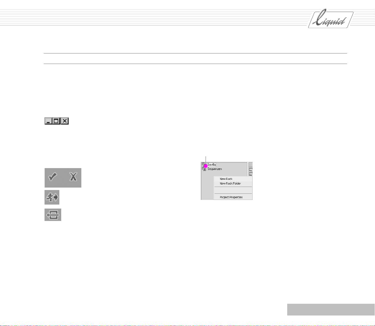
Minimize, Maximize, Close
There are also several symbols that you won’t recognize from
other products or devices.
Here are some symbols that you will often encounter in dialog
boxes and function modules:
The checkmark stands for OK or Apply
and the X stands for Cancel
The running man stands for Exit.
This button serves to close several
different modules.
Reset to default values
For a more extensive assortment of tool buttons, refer to the
Reference Manual, “Basics” chapter.
Text Styles
Text in italics refers to the software (for example, Menu Bar >
To o l s ) where “>” represents one step in a progression.
Keyboard shortcuts are also highlighted:
CTRL + A.
Shortcut Menus and Menu Bar
In developing Pinnacle Liquid’s visual design, there was one
overriding concern: keep it simple and easy to use. Most of the
functions are called either from a shortcut menu (right-click)
or by means of a tool button.
Alongside To o l s , Shortcut Menus are the principal operating
elements in Pinnacle Liquid. All useful functions are grouped
in these shortcut menus specific to objects and certain areas.
And that’s where you should look first.
Right-click here
Shortcut menu (example)
For some commands, you must first select a Rack or several
clips in order to indicate where you want to apply the function.
For example, if you want to import a clip, first select the Rack
to which you want to import it.
You’ll notice that the background of certain windows starts to
flash (light-gray – dark-gray). This means that the subsequent
action will be applied to this particular area. This is especially
helpful when, for instance, you have opened or selected multiple Racks.
Almost all these functions are also contained in the Menu Bar,
which wasn’t available in earlier versions of Pinnacle Liquid.
Chapter Introduction
1 - 3
Page 11
PINNACLE
In this User Guide, we’ll access some of the functions from the
Menu Bar. If you’re already accustomed to using shortcut
menus, you’ll have no trouble finding the corresponding commands there. Beginners will find the functions of the Input and
Output Wizards to be especially helpful. If you’re not sure how
to import or output material, turn to the appropriate Wizard for
assistance.
Call Input-Wizard
Call Output Wizard
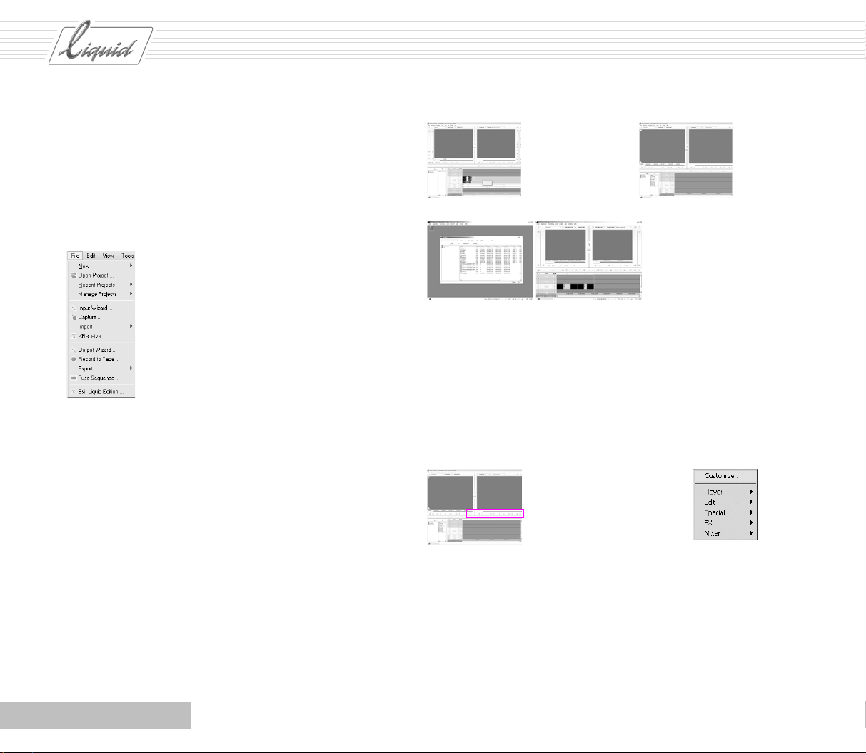
It Looks Different in the Book!
The User’s Guide is illustrated with many screenshots from
throughout the user interface. In some cases, the user interface
on your screen may look a little different. That’s because this
manual deals with several products that differ in a number of
details. The appearance of the user interface also varies
depending on the resolution of your particular screen. Our
screenshots are based on a specific resolution. They appear
smaller than they do at higher resolutions and a number of tool
buttons that fit beside the Vie wers at a lower resolution are
positioned below the Viewers at a higher resolution. So if Pinnacle Liquid uses the higher resolution on your computer and
you start running into problems simply because our screenshots look different from yours, don’t worry!
User interface at 1024 x 768 User interface at 1280 x 1024
Dual monitor operation:
Left - Project Window;
right - Sequence Editor
You can change the resolution by right-clicking on the Windows desktop to open the shortcut menu and selecting Proper-
ties. You can then adjust the screen resolution on the Settings
tab. You may have to reinstall Pinnacle Liquid before the software settings can take effect. There is also another setting that
affects the appearance of the user interface:
Right-click the Toolbar to open the shortcut menu and select
Customize to open the Function Library.
Toolbar
Right-click to open
shortcut menu
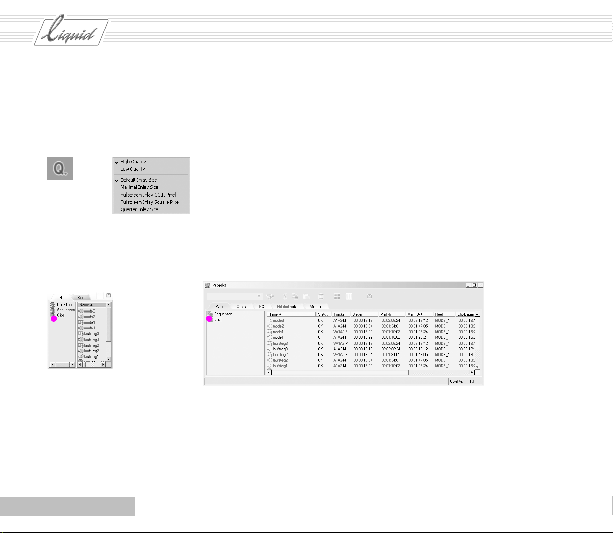
In the Function Librar y, select the Special tab. This tab contains
the Inlay Quality Menu button (Q symbol). While holding down
the left mouse button, drag the Q to an empty spot on the To o l -
bar or a place between two other buttons and drop it (see large
figure on the next page). Then click Close to close the Function
Library.
1 - 4
Chapter Introduction
Page 12
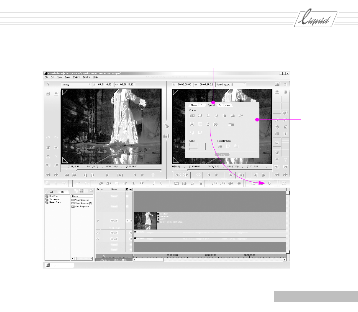
Special tab
PINNACLE
Function
Library
Chapter Introduction
1 - 5
Page 13
PINNACLE
Now click the Q button to open the Inlay Quality menu and
select the bottom option to change the display to the smaller
size (no checkmark) so that your screen will look like the
screenshot in the book.
Default Inlay Size
Project Browser Project Window
Because the work situation described in this document
involves only one monitor, the descriptions provided are based
on the use of the Project Browser for managing material. If you
happen to have two monitors, you have the option of using the
left-hand monitor for the Project Window. The Project Browser
and Project Window are basically the same thing – the elements
described here for the Project Browser can also be found in the
Project Window.
1 - 6
Chapter Introduction
Page 14
Where Do I Get the Buttons?
PINNACLE
If you come across tool buttons in the User’s Guide that don’t
appear on your Toolbar but can be seen in the screenshots at the
appropriate locations, don’t panic! They do exist. The procedure is the same as was described above for screen resolution.
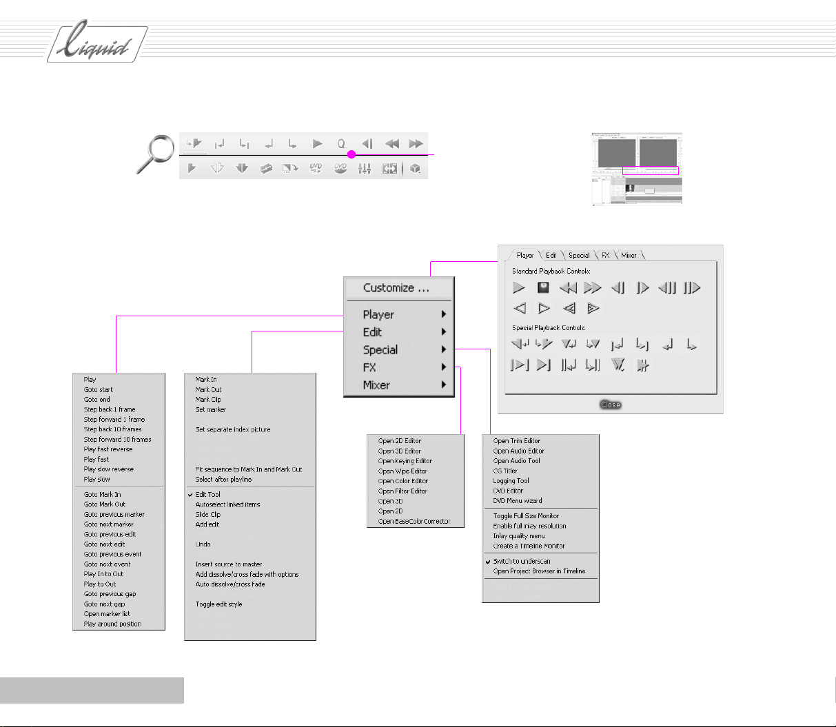
Right-click the Toolbar to open the shortcut menu. Select the
top option in the list (Customize) to open the Function Library
containing the functions for the current module, identified by
symbols. The Function Library contains all the buttons for the
specific module, including those already located on the Tool-
bar.
If you want to use a function repeatedly or at regular intervals,
use drag & drop (click to select, hold down left mouse button,
drag and drop) to position the button on the Toolbar. Like any
extensive library, our Function Library is organized by “sub-
ject”. For example, the Player tab contains the control buttons
that move the Playline to a specific position, whereas the Edit
tab contains Selection and Editing buttons.
To remove buttons that you never use or use only very seldom,
drag the button back to the Function Library. It makes no differ-
ence whether the correct tab is currently selected.
The same functions found on the tabs of the Function Library
are also contained in the list of functions for one-time
execu-
tion, but here they appear as text entries. The arrangement is
the same, i.e. the tabs of the Function Library correspond to the
five entries in the shortcut menu from which you can call the
functions to apply them once.
Be conservative when customizing the toolbar. In the beginning, leave things just as they are. Although the Reference
Manual tells you how to return everything to its original state,
you should use this procedure only when you have no other
choice. See the Reference Manual, “Customize” chapter.
Note: The shortcut menus may be only partially dis-
played, depending on the software module from which
you opened the menu.
Chapter Introduction
1 - 7
Page 15
PINNACLE
Toolb ar
Shortcut menu
Right-click the toolbar to open
the shortcut menu
Function Library – tabs correspond to the
entries in the shortcut menu
1 - 8
Chapter Introduction
Page 16
PINNACLE
Taskbar
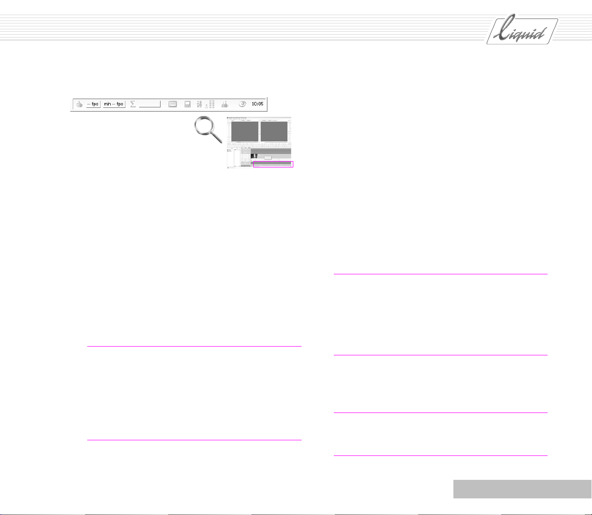
In the lower right-hand corner of the Taskbar, you’ll find sev-
eral important functions that are always visible. The “thumbs
up” icon tells you that the system started correctly. If a problem occurs, an exclamation point appears in the same spot. The
color of the exclamation point indicates the particular type of
problem (see the Reference Manual).
The sigma icon (the Greek letter S) represents the Render
Viewer window.
Rendering means the computation of effects. Click the S icon
to open the Render Viewer window, where you can monitor the
rendering process, and start and stop rendering. The horizontal
bar next to the window shows the rendering progress.
Note: Some effects (Classic effects) always require ren-
dering. For realtime effects – and depending on your system’s performance – the computations are sometimes too
time- and resource-intensive to be done in realtime (for
example, when multiple effects are applied simultaneously). In this case, the effects are still rendered and the
results are then written to a separate file.
The monitor icon stands for Video Output. When editing, you
always have the possibility of viewing the results of your work
on a video monitor or TV as well. To do this, you must have a
monitor connected to a breakout box via the analog ports. Then
select the appropriate cabling option for the Video Output.
These ports are available with the box that is supplied with the
product Liquid Edition PRO:
YUV, Y/C, CVBS, 1394.
If you select None (i.e. no output), a preview is available only
in the inlay. On the other hand, this is the smoothest way to perform scrubbing.
These settings again become important later on when you want
to output the sequence. Note that for DV-out in particular,
everything must be rendered.
Glossary: The breakout box is a connection box with var-
ious connection options connected to the computer via a
USB2 port or other interface.
The different products – Liquid blue, and Liquid Edition
PRO – use different breakout boxes. No box is delivered
with Liquid Edition.
To access several views for the Pinnacle Liquid interface, click
the View Switcher (eye icon) and select an available desktop
view.
Note: Right-click the Windows taskbar, select Properties
and in the dialog box displayed, deactivate the checkbox
next to Always on top.
Chapter Introduction
1 - 9
Page 17
PINNACLE
Keyboard Shortcuts
Finally, Pinnacle Liquid has many functions that can be executed via the keyboard. It is even possible to customize the key
assignments – i.e. to assign functions to keys – to match your
own personal preferences and requirements.
For example, if you’re used to using specific keyboard shortcuts from another program, simply configure these shortcuts in
Pinnacle Liquid.
In the User’s Guide, we will occasionally refer to the keyboard
shortcuts for specific functions. These shortcuts are based on
the default keyboard assignment. As soon as you customize the
keys to suit your own needs, you may find that you can’t execute certain functions as described in the User’s Guide.
The same applies here as to customizing the Toolbar: Be very
conservative in your use of this option and, if at all possible,
don’t start changing assignments until you’ve read through the
User’s Guide.
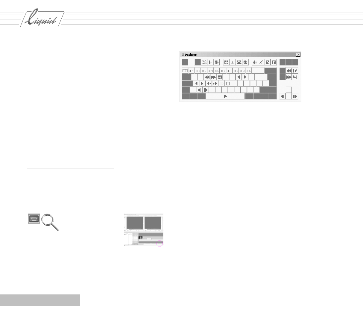
To view the commands that can be executed in the current
module, click the Key boa rd (Key Caps) icon in the Taskbar.
Keyboard assignments for the desktop
If you want to change the assignment:
Select Pinnacle Liquid Menu Bar > Edit > Control Panel to open
the Control Panel and then double-click Keyboard Settings to
open a dialog box.
In the Keyboard Settings dialog box, open the drop-down menu
and select the module for which you want to change the assignment. Global Shortcuts indicates the commands that are available in each module. In the event of a duplicate assignment –
module-specific and Global Shortcuts – the module-specific
shortcut has priority.
On the right side of the dialog box, a toolbox is displayed containing the functions represented as symbols. Use drag & drop
to assign the functions to keys.
1 - 10
Chapter Introduction
Page 18
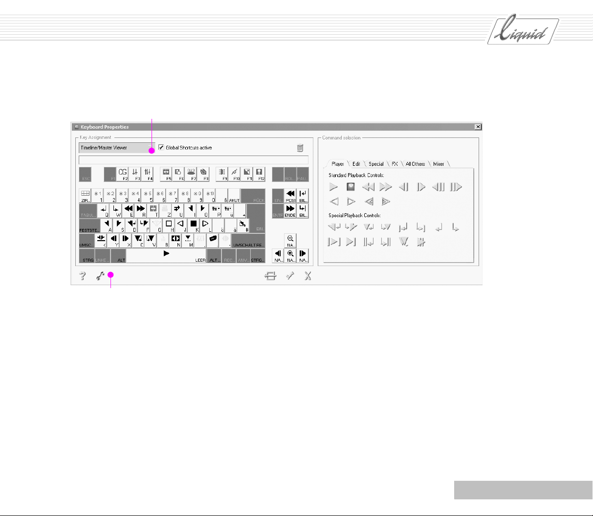
Drop-down menu
Open/close the toolbox
PINNACLE
Chapter Introduction
1 - 11
Page 19
PINNACLE
But First ...
If you run Pinnacle Liquid with only one controllable device
(generally a DV camcorder):
1 Connect the device.
2 Switch on the device.
3 Start your computer.
4 Start Pinnacle Liquid.
In nine cases out of ten, Windows automatically detects the
device.
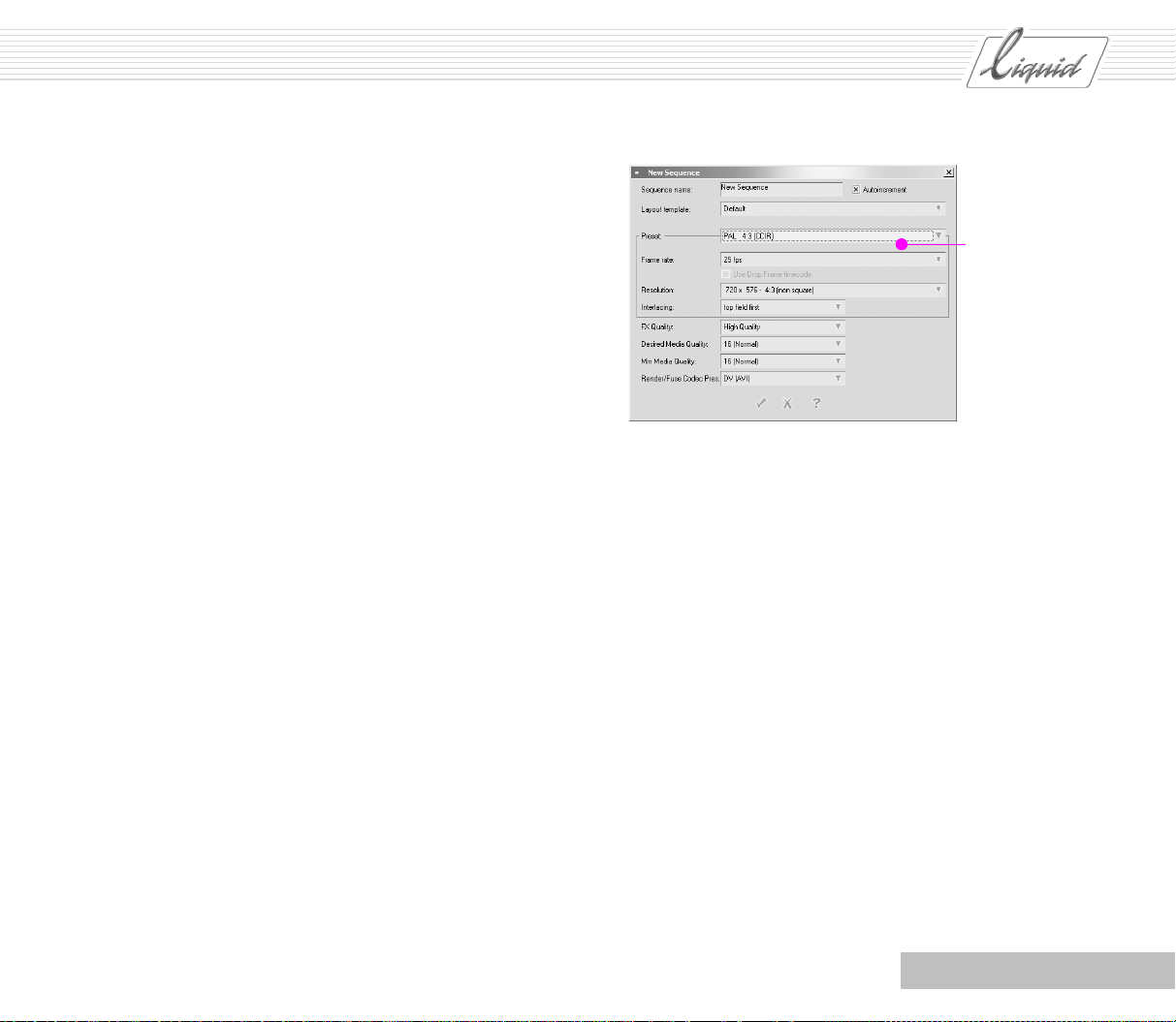
The first time you start Pinnacle Liquid, the New Sequence dialog box opens automatically. Enter a suitable Name in the f ield
provided and an appropriate Format under Edit Presets. Don’t
change the entries in the other fields; they represent default
values for the particular Formats. The first four settings are followed by the abbreviation “CCIR”, referring to an international standards committee.
Avoid changing the Format unnecessarily. Create your
Sequences using a uniform Format, play them in this Format
and output them in this Format. See “Standards and Formats”
on page 1-12.
Some of the problems that can arise during the initial steps
have to do with the settings related to your equipment.
So take a little time to read the corresponding section in the
Product Manual.
As far as possible, Pinnacle Liquid functions independently of
your equipment. Nevertheless, two important tools require settings that regulate interaction with your equipment and will be
mentioned here. These are the Logging Tool (Capture), which
processes video material played from your system, and the
Record To Tape module.
Differences exist between the Liquid Edition, Liquid Edition
PRO and Liquid blue products. Because each product can also
be operated in combination with different devices, the specific
settings are beyond the scope of this User’s Guide. At this
point, we’ll just briefly describe Media Management.
Standards and Formats
As far as the different Formats and standards are concerned,
you should at least understand the background. The Formats
are determined by four basic parameters:
Resolution,
Aspect Ratio,
Frame Rate and
Interlacing.
Increasing the Resolution improves image quality. A higher resolution lets you show images in more detail, but may also
reveal unwanted details.
The Aspect Ratio refers to the traditional 4:3 format and the
16:9 (widescreen) format.
1 - 12
Chapter Introduction
Page 20
Many additional combinations are possible with Frame Rate
and Interlaced/Non-interlaced. In this context, the second
parameter refers to full-frame or field interlacing, as was formerly common in television standards. With full-frame interlacing, image sequences containing a lot of movement flow
more smoothly.
After examining the format options, determine the format(s) of
your original material and consider your own purposes for outputting the fully edited Sequence later on.
For example, if most of your original material was processed at
a resolution of 720 x 576 pixels, it wouldn’t make sense to
choose a higher resolution for the Sequence because this would
only have the appearance of improving the quality.
The same is true of the Aspect Ratio: If almost all of the original material was filmed at a ratio of 4:3, stick with this ratio.
Note that inserting elements with other Aspect Ratios results in
black bars or a cropped image. Although there are a few such
elements that can be incorporated in a Project, they should
remain the exception.
With regard to the Frame Rate, only one Timecodec System can
be used in the current Sequence. Clips using a different Time -
code System are played at the Sequence’s Frame Rate. Frames are
omitted or new Frames interpolated as necessary – one second
is still one second.
For all these reasons, you can take full advantage of HD video
only if you use suitable material throughout. Large-format projections, such as those used for lectures, will turn out better.
Preset
Formats
PINNACLE
Chapter Introduction
1 - 13
Page 21
PINNACLE
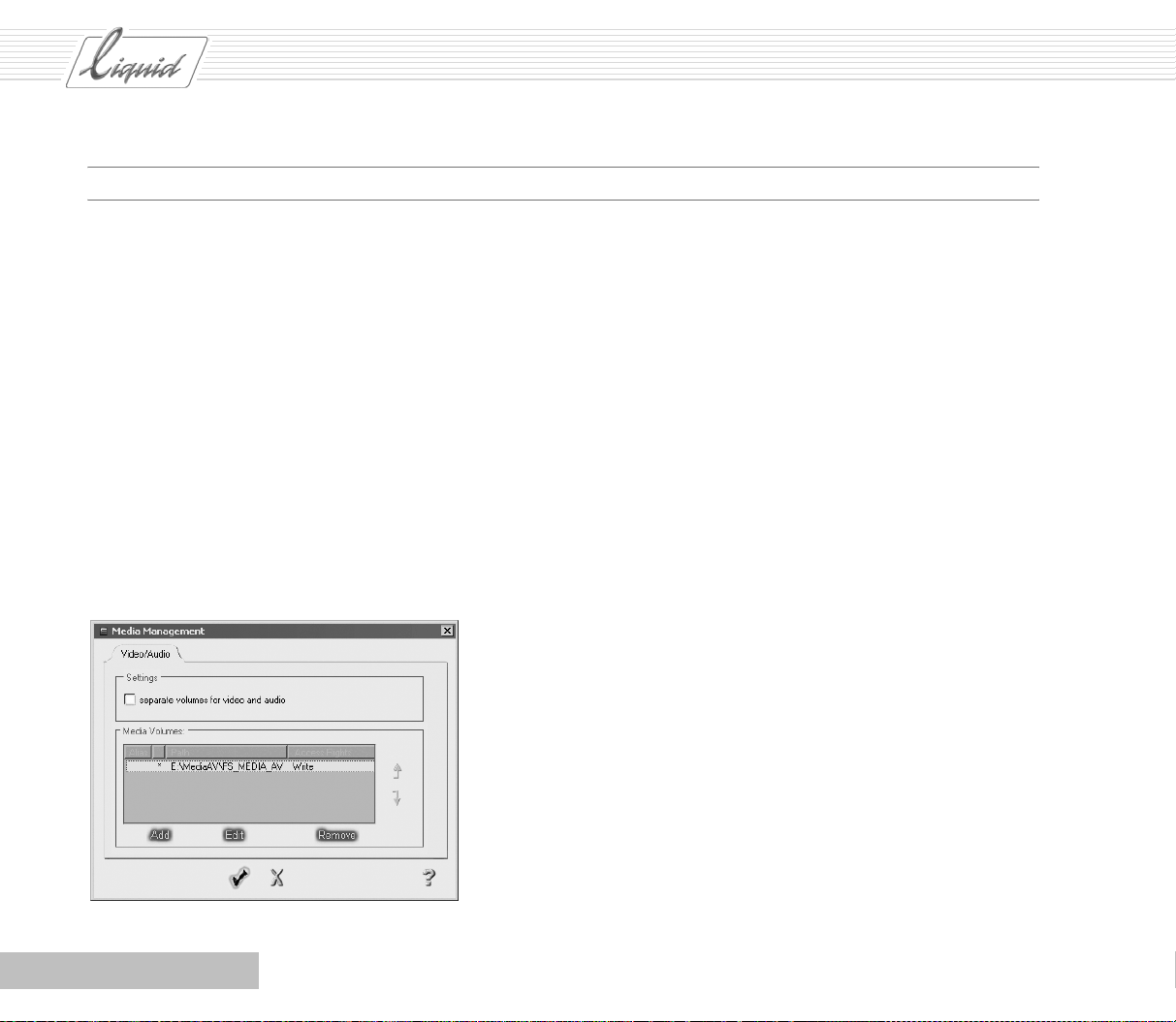
Media Management
When you installed Pinnacle Liquid, you already defined a
storage location for data you transfer to your system. You can
look up these settings in the Media Management dialog box and
modify them.
Select Pinnacle Liquid Menu Bar > Edit > Control Panel > Site
> Media Management Settings.
Although a hard disk is a high-capacity storage medium, often
one hard disk is not enough. “Drive” is a superordinate term
for a data medium.
Many computers now have several hard disks installed; Media
Management Settings lets you administer these drives.
See also “Alternative AV Drives/Directories” on page 3-18. Here
you will find instructions on how to add drives.
1 - 14
Chapter Introduction
Page 22
PINNACLE
Chapter
Quickstart
Contents
What Do You Want to Do?........................................................................................... 2-2
Step by Step ..................................................................................................................2-2
Inserting Clips on the Timeline .........................................................................................2-9
Output .........................................................................................................................2-20
Output with the RS 422 Control Protocol....................................................................... 2-22
General
First a few preliminary remarks:
This Quickstart chapter is intended to familiarize you with the basic functions of Pinnacle Liquid. In order
to get the desired results, it’s important that you follow the steps exactly.
If you happen to hit a wrong key, button or menu click the Undo button to restore the previous state.
2
Undo button
It is assumed that your system is correctly configured, Pinnacle Liquid is installed and you have a play
source (camera or recorder) plus one recorded tape and
one blank tape.
Page 23
PINNACLE
Text in italics refers to the software (for example, Menu
Bar > Tools) where “>” represents one step in a progres-
sion.
Saving: With Pinnacle Liquid you don't need to give it a
second thought because the Instant Save technology
ensures that every single step and every change is saved
immediately.
What Do You Want to Do?
You want to cut your video material, edit it and then output it
again. The workflow looks like this:
Step by Step
Before starting the software (by double-clicking the icon on
the desktop), connect your camera (or your player or output
device) and switch it on. If your device is a DV device, it will
be detected automatically when you boot the software.
After booting the software, you would normally either continue working on a Project you previously started or create a
new Project. Let’s do just that:
1 Transfer the material to your computer.
2 Edit the material – for example, by trimming it and apply-
ing an effect.
3 Output the material to a tape, SVCD or DVD.
Note: While filming, you should already be concentrating
on producing a consistent timecode and making sure you
have a little extra material before and after your scenes.
Leave the tape in the camera for as long as you want to
continue recording more material and use short tapes.
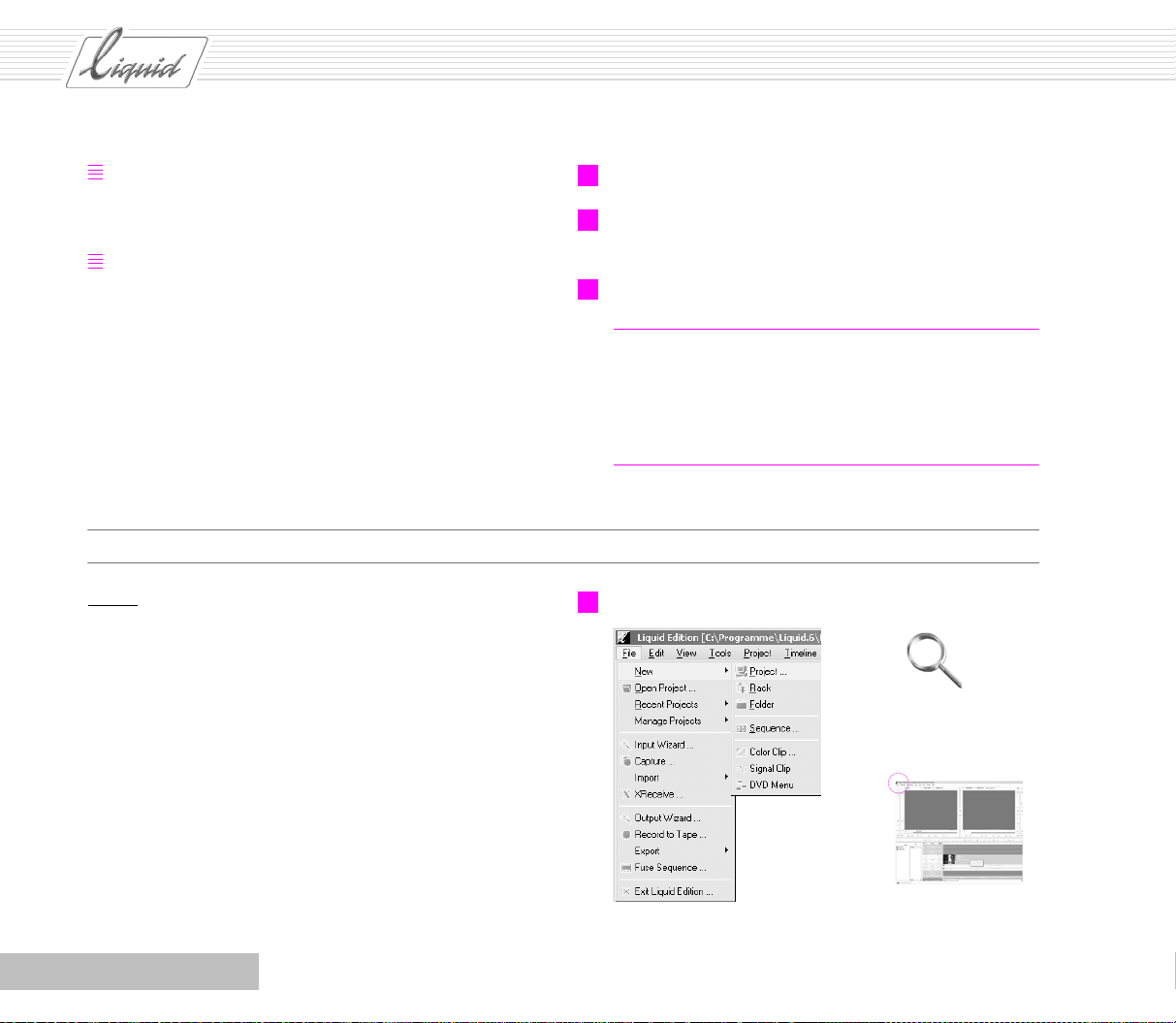
1 Select Pinnacle Liquid Menu Bar > File > New > Project.
2 - 2
Chapter Quickstart
Page 24
PINNACLE
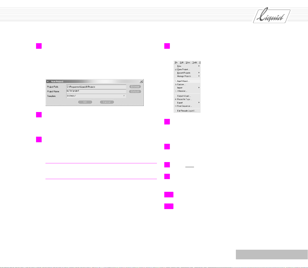
2 In the dialog box displayed, enter a Project Name of your
choice and click OK to confirm.
We’ll start out using the default template for this Project.
We’ll also retain the default storage location for the Pro-
ject. Later on, you’ll create your own templates.
3 Use the View Switcher to display the Timeline on the bot-
tom and the Sequence Editor on top (see large figure, bot-
tom right).
4 Insert a (recorded) tape in your player. (For the steps that
follow, it is assumed that you use a controllable DV
device for playback.)
Note: A Project is made up of Sequences, which are in turn
made up of clips (video, audio, titles...).
5 Select Pinnacle Liquid Menu Bar > File > Input Wizard to
open the Input Wizard.
6 For this example, click the top icon (with the video cam-
era) in the Input Wizard; this icon represents playing a
video device.
7 The Select A Rack dialog box is displayed. Select New
Rack to create a new Rack.
8 Enter your name for your new Rack and then click Create.
9 A Rack with this name is then added to the list in the Sel-
ect A Rack dialog box.
Chapter Quickstart
10 Select this Rack and click Select.
11 The Logging Tool is now displayed.
2 - 3
Page 25
PINNACLE
12 You are prompted to select a Reel. Because this is the f irst
time, type in a name. Especially in the case of Projects
where multiple tapes are used, it’s important that you
select a unique name that is significant for you. If appropriate, combine names and numbers (Spain1, Spain2), but
never use the exact same name twice. If your DV cassette
already has a name (such as Spain1), simply assign the
same name to the Reel.
13 Click Apply and Close (checkmark).
Glossary: Reel is simply the name of a signal source, usu-
ally a video cassette but it can also be a live TV signal.
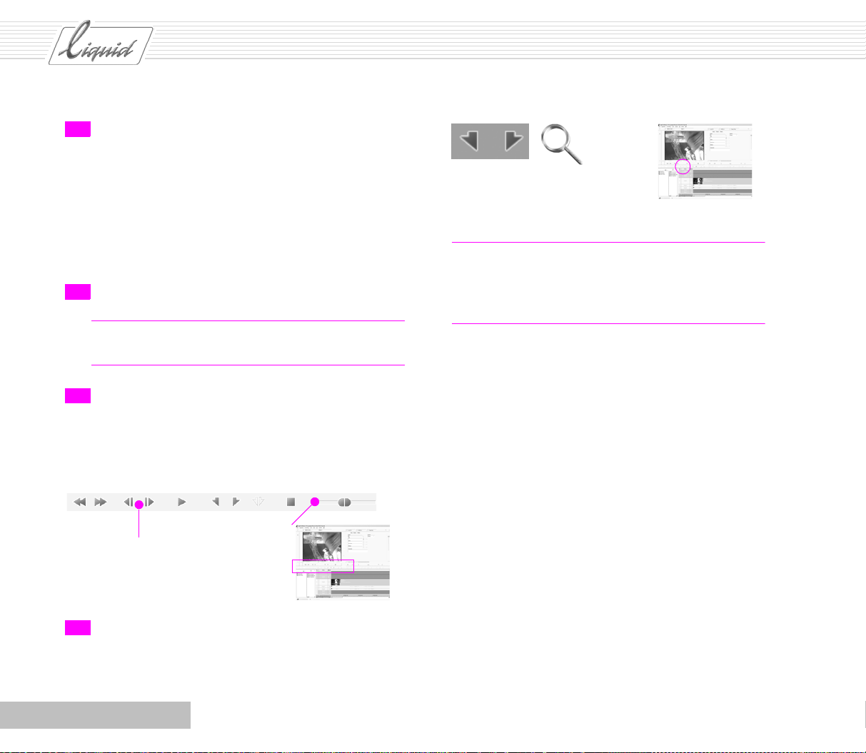
14 Use the control buttons to shuttle the tape back and forth
in the player. In addition to the buttons you’re already
familiar with from other devices – Play, Stop – you will
also find a Shuttle button.
Mark-in / mark-out
Glossary: The Mark- in is the starting point and the Mark-
out is the end point. Be generous in your definition of
clips so you’ll have enough leeway later on when you
trim. See “Leeway” on page 5-2.
1 frame
ahead/back
Shuttle: Using the
mouse, drag the
slider in order to
fast-forward or
rewind
15 Set a Mark-in at the beginning of the scene and a Mark-
out at the end. Try to create a clip that’s about 20 seconds
long. That will be sufficient for the exercises that follow.
2 - 4
Chapter Quickstart
Page 26
13
Apply and Close
PINNACLE
View of
Timeline
and
Sequence
Editor
Chapter Quickstart
Click eye to open menu
3
2 - 5
Page 27
PINNACLE
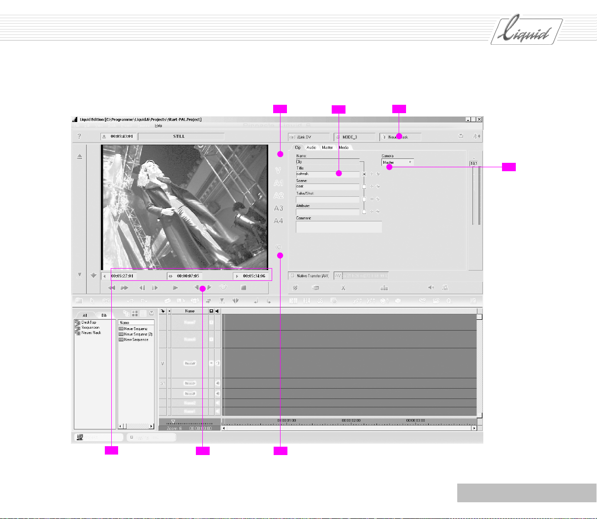
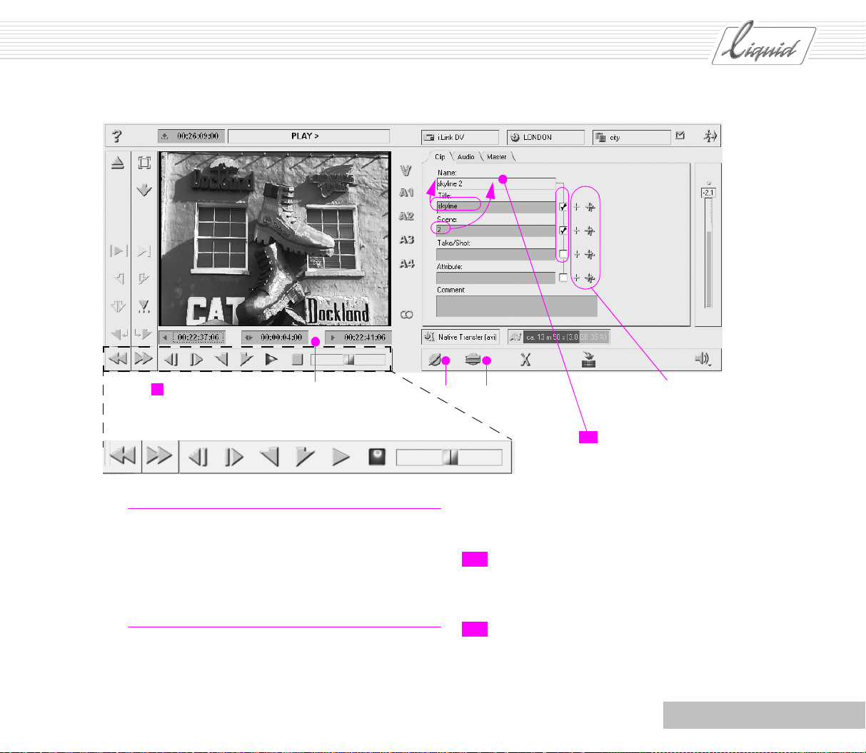
16 The Timecode fields below the Viewer contain the values
for the Mark-in and Mark-out as well as the length of the
clip you just defined.
17 Before selecting the audio channels, look at the Au dio tab
to see exactly what you’re dealing with.
Register
Audio
18 Should this clip be a video clip or an audio clip, or should
it contain both? Activate the Source tracks by clicking V,
A1 - A4 (yellow = active). The Audio tab shows input
only for 1 and 2, only these Source tracks (V, A1, A2) can
be digitized.
Note: Mono audio clips are set to “Center” at the Master
output (right and left channel played at the same volume).
In the case of Stereo Audio Clips, the left/right distribution
of the source material is of course retained.
20 You need to name the clip. Select the Clip tab and type in
a name under Title.
21 Click the checkbox to the right of the appropriate text box
to add the entry to the Clip names.
Click an individual plus sign to increment the count by
one. If you activate automatic counting (double plus
sign), numbering is performed automatically.
22 A field in the upper right-hand corner displays the Rack
for the clips.
Note: Clicking the name of the field opens a list from
which you can select an existing Rack.
Double-clicking the icon opens a dialog box for creating a
new Rack.
Glossary: Source tracks – Tracks containing the original
material.
19 Mono or Stereo? One ring means Mono and two rings
mean Stereo. If your camera records stereo sound, select
Stereo.
2 - 6
Glossary: Rack – The place where clips are stored.
Chapter Quickstart
Page 28
PINNACLE
18
20
22
21
16
Chapter Quickstart
15
19
2 - 7
Page 29
PINNACLE
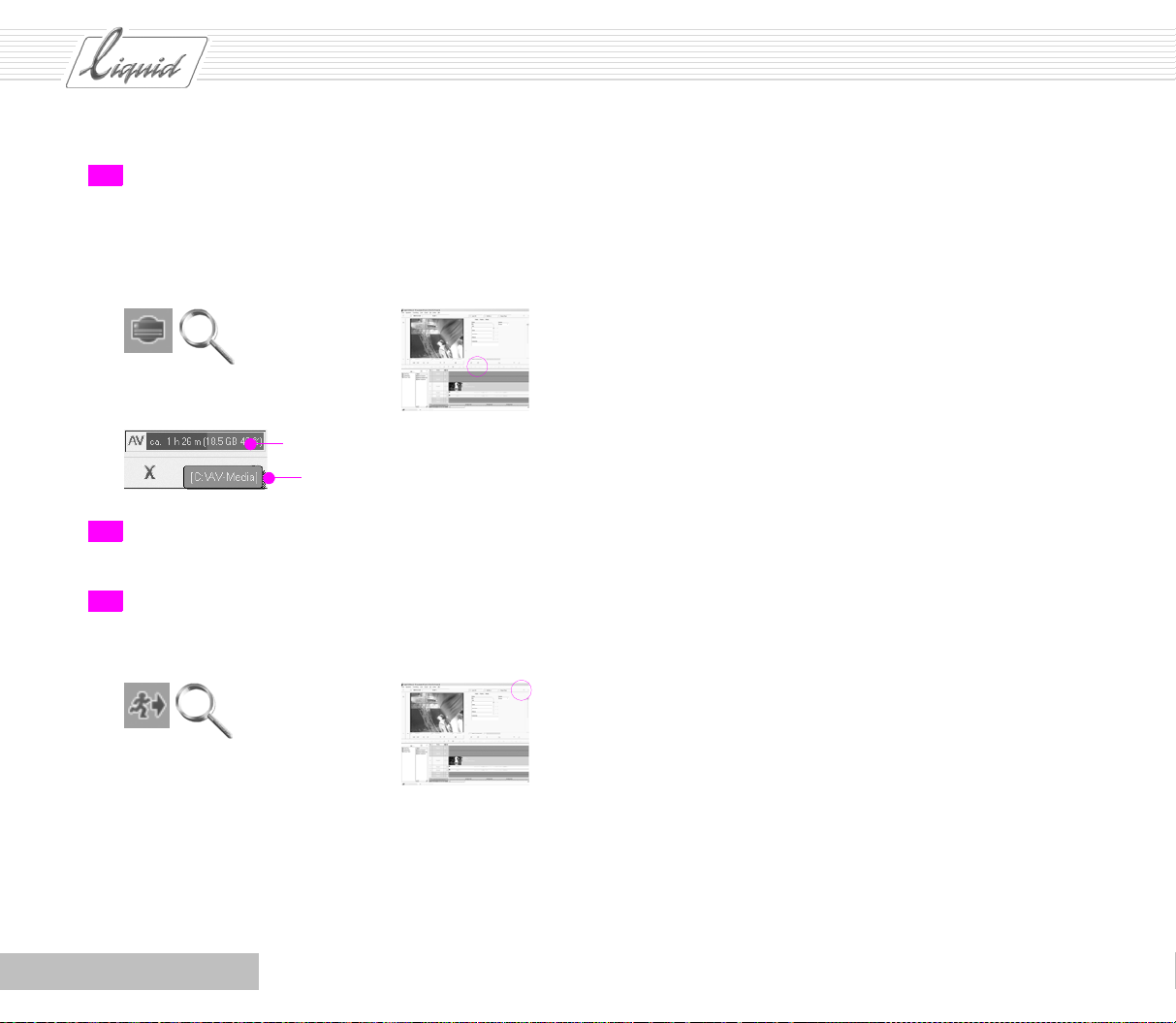
23 Digitizing (capture): Click the Digitize button. The player
goes to the Mark-in and starts digitizing the material, i.e.
starts saving it to the hard disk that appears in the AV f i e ld
when you move the mouse pointer across it.
Digitize button. Button flashes red during the digitizing process.
Move mouse across this field
Read storage location here
24 Repeat Steps 14 to 23 until you have digitized a total of
five clips.
25 Click the Exit button (running man) to exit the Logging
To o l .
2 - 8
Chapter Quickstart
Page 30
Inserting Clips on the Timeline
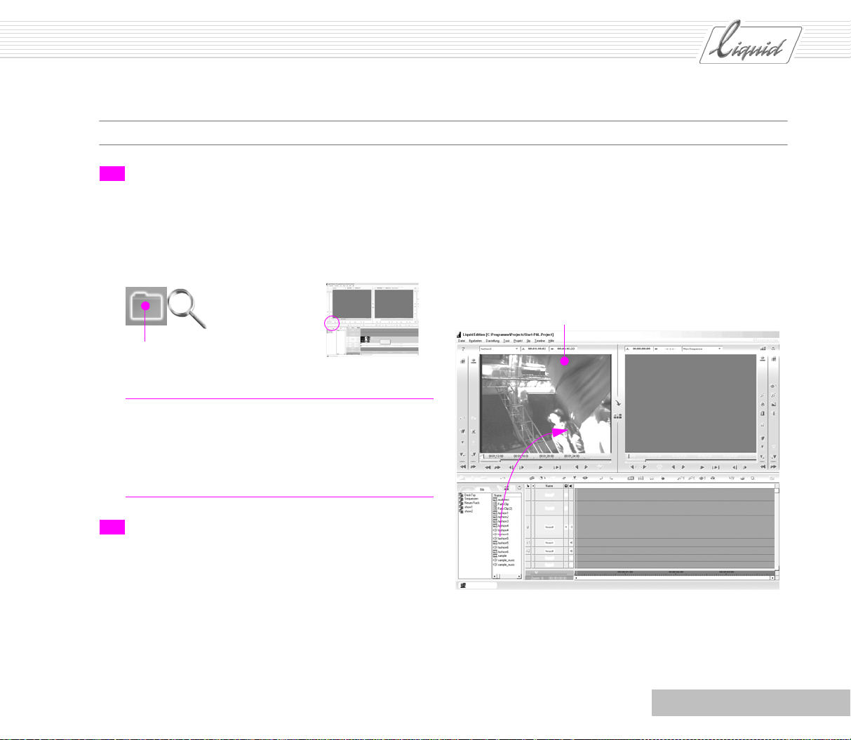
26 In the Project Browser, click the Rack that you selected for
your clips. If you’re working with two monitors, use the
View Switcher to select a view where one of the monitors
displays the Project Window. Then perform the steps
described below in the Project Window instead of the Pro-
ject Browser.
Open Project Browser
Glossary: The Project Browser serves to administer clips
and effects.
Drag & drop: Click the clip to select it, hold down the left
mouse button, drag the clip to the desired location and
drop it.
PINNACLE
Source Viewer
27 Use the drag & drop method to drag the first digitized clip
to the Source Viewer. As soon as the mouse pointer is
located on the Source Viewer, another arrow appears next
to it. You can now drop the clip.
Chapter Quickstart
2 - 9
Page 31
PINNACLE
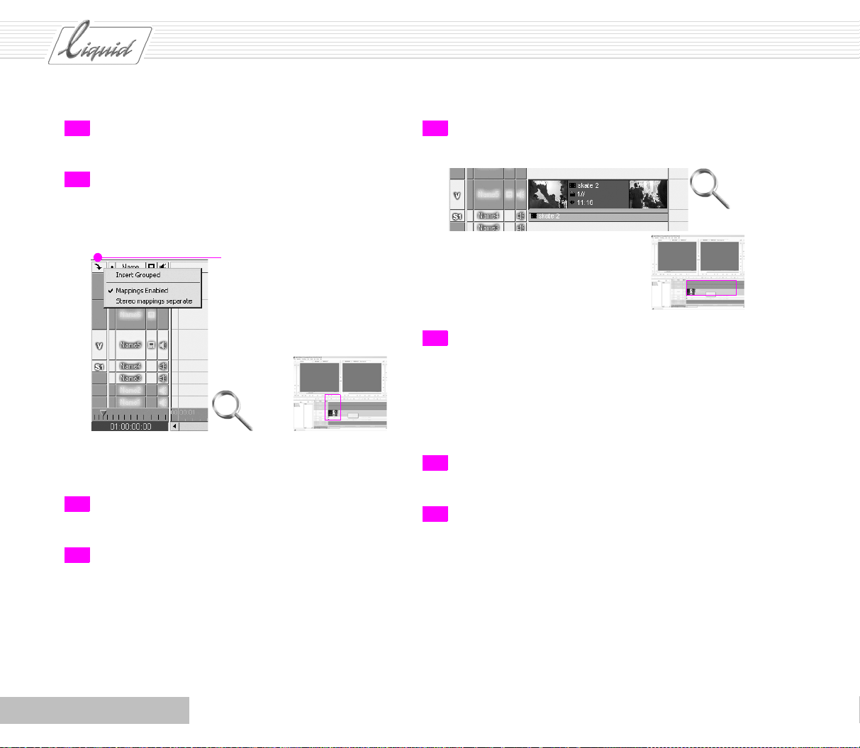
28 Use the control buttons to shuttle back and forth and set
slightly more precise Mark-in and Mark-out points.
29 Right-click the Source track mapping button to open this
menu. Single-clicking the options activates (checked) or
deactivates them. Set the options to match those in the
figure below.
Right-click here to open menu
The audio and video clips are then automatically positioned on different Tra c k s .
30 Click the button between the viewers so that the yellow
symbol indicating Film Style appears.
31 Click the Insert Arrow to insert the clip on the Timeline .
32 The clip is inserted on the Timeline and the Playline is
positioned after the inserted clip.
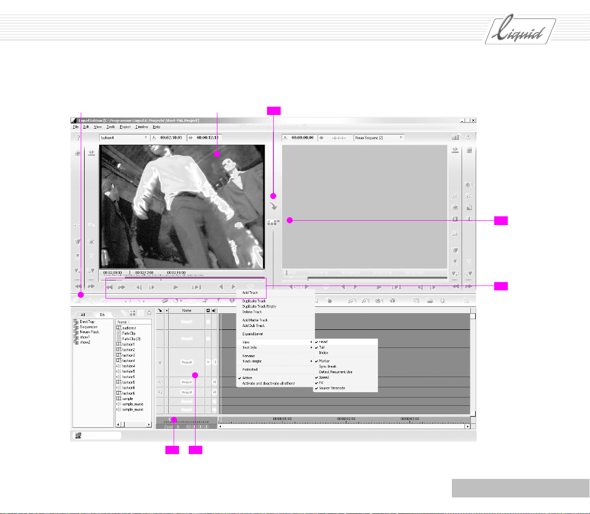
33 If your screen looks a little different, it might be due to
the Trac k v ie w. To change the view, right-click the Tra c k
name to open the shortcut menu and select View. In our
example, Head and Ta i l are activated (checkmark visible).
This displays the first and last frame of a clip, as far as the
Zoom Control permits.
34 Use the Zoom Control to adjust the Timeline scale so that
the entire clip is visible.
35 Repeat Steps 27 to 31 until all five digitized clips are
positioned consecutively on the Timeline.
2 - 10
Chapter Quickstart
Page 32
Open/close
Project Browser
Source Viewer
PINNACLE
31
30
28
Chapter Quickstart
34 33
Open shortcut menu
2 - 11
Page 33

PINNACLE
36 Use the Zoom Control to adjust the Timeline scale so that
all the clips are visible.
Note: For simplicity’s sake, we’ve inserted clips of the
same type on the Timeline in Film Style. One Tr a c k con-
tains the video clip and one Tr a ck contains the audio clip.
Glossary: Tr a ck s – In the example, the video information
is contained in a video clip on one Tr a c k and the audio
information is contained in a stereo audio clip on a second
Tr a c k . The Source track labels are located to the left (V for
video and S1 for stereo – corresponding to the clip, that is
actually in the Source Viewer).
37 Yo u r Timelime should now look something like this.
Source track labels
38 Make sure you’re in Edit mode. The mouse pointer is
accompanied by a filmstrip symbol. As you move it
closer to the edits, this symbol changes to a mark-in or
mark-out symbol.
39 Click the first clip near the first edit. A yellow line now
appears on the clip that serves as a handle. Using the
mouse, drag the Handle at the end of the first clip in the
direction of the beginning of the Timeline, thus trimming
the clip.
40 In the next step, you’ll trim the clip a little more precisely.
To do so, click the appropriate button to open the Tr i m
Editor.
Note: A clip cannot be longer than the associated Media
file. If the full length of the Media file is used (no Mark-in
/out), we talk about Clip-in and Clip-out.
41 The Viewer on the left now contains the last frame of the
Outgoing clip and the Viewer on the right contains the first
frame of the Incoming clip. The gradient bars below each
Viewer indicate that trimming is currently being applied
to both clips. On the Time line, yellow handles appear on
both sides of the Playline.
Glossary: Outgoing clip – The clip that ends at this point.
Incoming clip – The clip that starts at this point.
2 - 12
Chapter Quickstart
Page 34

PINNACLE
Gradient
bar
40
Trim Editor
38
Chapter Quickstart
Yellow handles on both sides
2 - 13
Page 35

PINNACLE
42 Click the image in the Viewer on the right so that you will
be trimming only the right-hand clip. The gradient bar
now appears under the right-hand Viewer only.
43 Use the tool buttons to move the edit. Click the Trim 10
Frames Right button four times to move the Mark-in of the
second clip (the Incoming clip). Click the middle tool button to display a Preview. In the default configuration, the
Preview shows one second of the Outgoing clip and one
second of the Incoming clip.
Trim 10 Frames Right
44 Click the appropriate button once again to exit the Tri m
Editor.
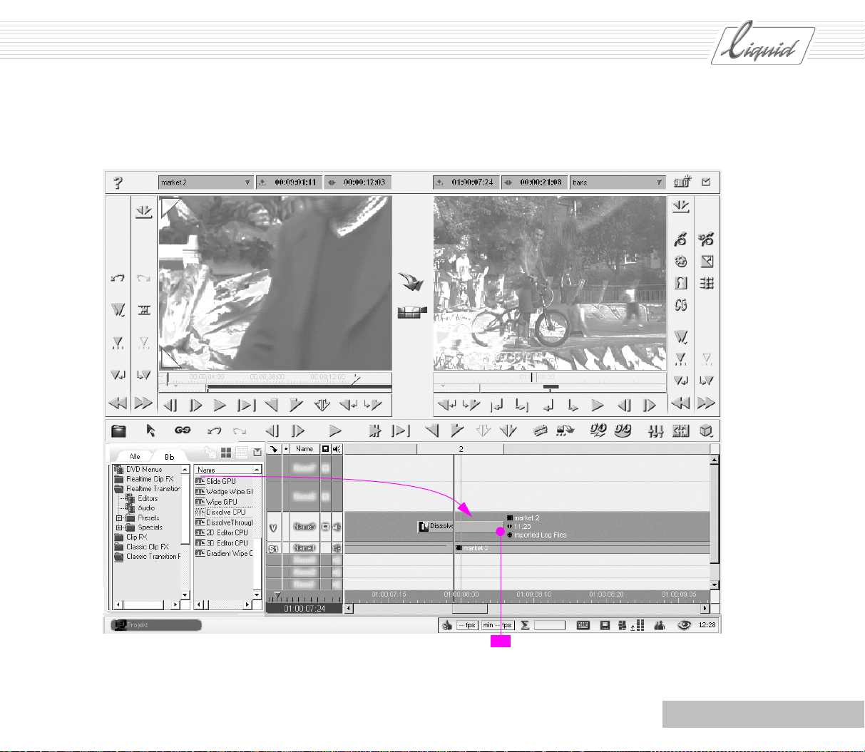
46 Open the Editors Rack in the Realtime Transition FX folder.
Lib tab
Rack Editors
47 Click the Dissolve CPU effect to select it, hold down the
left mouse button and drag the effect to the edit between
the first and second clips. The mouse pointer changes to a
rectangle whose length corresponds to the length of the
effect and is also accompanied by a plus sign.
48 Release the mouse button. A gray bar appears that repre-
sents the Tra n s i t i o n .
If your system isn’t powerful enough to display the effects
in real time, rendering is performed and a pulsating sigma
sign appears in the Taskbar.
Note: Classic Effects, which correspond to and have the
same names as the Realtime Effects, are always rendered.
45 In the Project Browser, click the tab to display the effects.
The tab must now read Lib (for “Library”).
2 - 14
Chapter Quickstart
Page 36
PINNACLE
Chapter Quickstart
48
2 - 15
Page 37

PINNACLE
Note: If part of the bar is red, this means there isn’t
enough leeway. (See “Leeway” on page 5-2.) In other
words, the clips don’t overlap enough to permit a Transi-
tion of this particular length.
In this case, trim the clips as described in Step 39 (in Film
Style – yellow symbol) until the entire bar is gray. You
must drag the Mark-out handle of the first clip toward the
beginning of the Timeli ne or the Mark-in handle of the
second clip toward the end of the Timeline (i.e. to the
right).
49 Use the Zoom Control to adjust the Timeline scale so that
the next edit on the Timelin e is also visible.
Right-click the gray bar to open the
shortcut menu
Make sure you’re still in Film Style, as indicated by the
yellow symbol between the Viewers.
50 Now insert another effect using the 2D Editor CPU. Open
the Editors Rack in the Classic Transition FX folder, hold
down the left mouse button and drag the 2D Editor CPU to
the edit between the second and third clips. Again, trim
the clip until the bar is completely gray.
51 Right-click the gray bar (the effect) on the Tim eline to
open the 2D Editor CPU and from the shortcut menu displayed, select Edit (or double-click the effect).
2 - 16
Chapter Quickstart
Page 38

Film Style indicated by
yellow symbol
PINNACLE
Chapter Quickstart
5150
2 - 17
Page 39
PINNACLE
52 If necessary, click the Goto Previous Keyframe button to
jump to the beginning of the effect. If you’re currently
positioned in the middle of the Tra n s it i o n, a new Ke yf rame
would be automatically generated by settings that you
enter at this location.
53 On the left-hand side of the 2D Editor, click the Size tab.
For all Tra n si t i on s , the settings you now enter are normally applied to the Incoming clip. That is exactly what
you want to happen here. The Incoming clip should start
out very small, then grow larger until it replaces the Out-
going clip.
54 Drag the slider to the left to set a size of about 15%. If
your mouse has a mouse wheel, you can use it to enter a
more precise setting. As long as the Lock function is activated (lock symbol), He ight and Width will change simultaneously, i.e. will be scaled proportionally.
The change in size is immediately visible in the viewer,
meaning that you can adjust many settings by sight alone.
To the right of the drop-down menus for effect parameters
is a graphical representation of the parameter(s). Each
parameter is displayed separately here because each individual parameter can have its own Key frame s. For instructions on working with this curve, see the Reference
Manual.
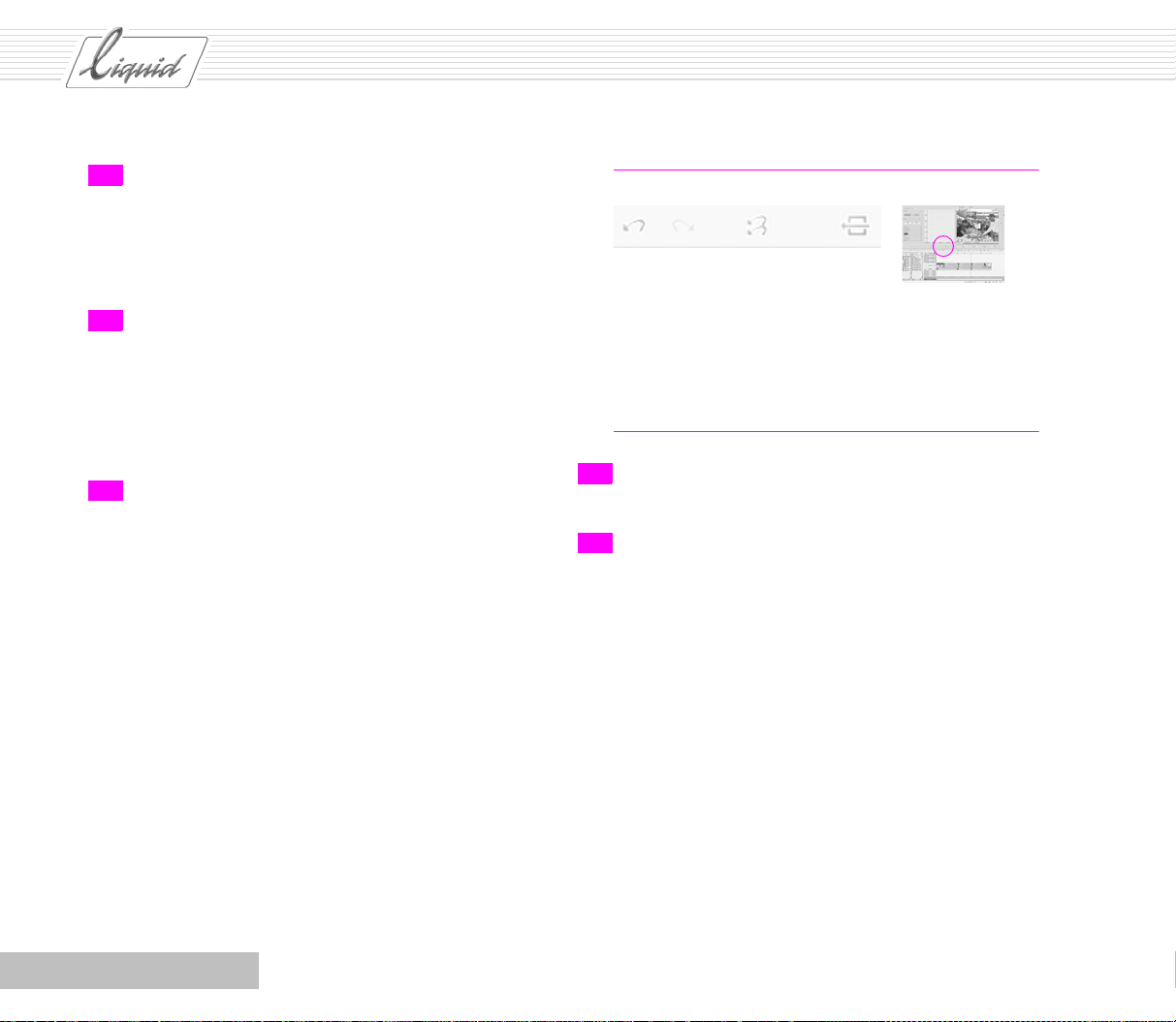
Note: The toolbar contains several useful buttons.
Undo, Undo to initial state, Default
Undo reverses only the last step performed. Undo to initial
state reverses all the steps performed since the editor was
last opened, but does not affect any settings made previous to this last opening. Some editors have default values
that can be restored by clicking the corresponding button.
55 Click the Exit Editor button (running man) to exit the 2D
Editor.
56 Click the Play In to Out button to view the entire Sequence.
If you haven’t set a Mark-in or Mark-out on the Timeline,
the entire Sequence is played back in a loop, i.e. from the
first clip’s Mark-in to the last clip’s Mark-out.
2 - 18
Chapter Quickstart
Page 40

53 54
The clip is immediately displayed
in the viewer at the new size
PINNACLE
55
You can
also enter
many
settings by
clicking the
tool
buttons to
the right of
the inlay
52
Chapter Quickstart
2 - 19
Page 41
PINNACLE
Output
57 It’s time to output the finished Sequence. Make sure a
recording device with an blank tape is connected.
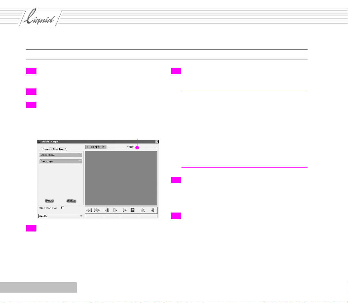
58 Select Pinnacle Liquid Menu Bar > File > Record to Tape.
59 In the Record to Tape dialog box, a status message such as
STILL or STOP should appear above the inlay.
If this says “DEVICE NOT READY”, check the cables and make
sure the device is switched on and ready to record.
60 On the left side of this dialog box, the top list box should
contain the text Entire Sequence. The name of the manufacturer of the recording device currently registered in the
system may be displayed at the very bottom.
61 To output via DV-O ut, the Render yellow slices option must
be activated.
Note: If the bottom line reads No recording device or con-
tains the wrong device, click the arrow and select Edit
Player to display a dialog box in which you can enter the
appropriate settings. The entry at the bottom left designates the device used for output or the control protocol (in
our example, 1394). Another entry may appear here. If the
preset entry does not match your device, click the triangle
to open a list and select another option.
See “Output with the RS 422 Control Protocol” on page
2-22.
62 Click Record. Everything else will happen automatically.
You can monitor output in the inlay. The Playline follows
along on the Timeline until the entire Sequence has been
played.
63 As in other applications, click the “X” to exit Pinnacle
Liquid.
2 - 20
Chapter Quickstart
Page 42

58
PINNACLE
63
56
Chapter Quickstart
2 - 21
Page 43

PINNACLE
Output with the RS 422 Control Protocol
The RS 422 control protocol offers options for output. Output
can be performed by Insert or Assemble.
Glossary: RS 422 – A standard for transmitting serial
data over medium distances (up to 300 m).
RS 422 interfaces are extremely common in professional
video technology and are used to control devices remotely.
Insert
If you select Ins ert, you must activate the relevant Tra c k s
manually.
In this case, “Tr a ck s ” does not refer to Audio Source Tracks or
Timeline Tracks, but to those tracks that are actually in the rele-
vant video format and supplied by the recorder. The particular
options available for selection depend on the features of the
recorder selected in the Player Settings dialog box.
Example: You have already output a particular Project to your
tape. Now you just need to replace a small dubbed Sequence. In
this case, select Inser t and apply it only to the corresponding
Audio Tracks. The tape to which you output the sequence must
be the same, i.e. the Timecode of your Timeline must exactly
correspond to the tape’s Tim ecode. Of course, the Ti melin e can
also be configured accordingly.
Assemble
Assemble allows you to record on a tape that was not completely precoded (striped). The tape recorder continues writing
the Timeline timecode. No segments can be inserted by means
of Assemble, since the exit at the mark-out most probably
includes breaks in the control track. As a rule, code for a few
minutes or even just seconds at the beginning of the tape to
enable a correct cut-in scene. Should the recording be interrupted, you have to continue within the coded range.
As is the case with Du mp To Ta p e , this option offers no track
selection, i.e. all tracks available on the machine are overwritten.
2 - 22
Chapter Quickstart
Page 44

PINNACLE
Chapter
Recording AV
Contents
General .........................................................................................................................3-2
What You Need (Checklist).......................................................................................... 3-3
Step by Step ..................................................................................................................3-4
Plus ... .........................................................................................................................3-10
LIVE Player............................................................................................................... 3-10
Analog IN ................................................................................................................ 3-12
Direct Insertion ........................................................................................................ 3-14
Tracks and Mapping................................................................................................... 3-15
Tips .............................................................................................................................3-16
Tape Has Identical TCs ............................................................................................... 3-16
Breaks in the Timecode .............................................................................................. 3-17
Alternative AV Drives/Directories................................................................................. 3-18
When to Digitize As Stereo and When As Mono?............................................................. 3-20
Methods: Log, Digitize All or Scene Detection? .............................................................. 3-21
Batch Digitize (Capture)............................................................................................. 3-21
Automatic Scene Detection in the Logging Tool............................................................. 3-22
3
Page 45

PINNACLE
General
You want to transfer video and audio material from a play
source to your Pinnacle Liquid system hard disk(s) (capture
procedure, Digitize).
Solution: The Pinnacle Liquid Logging Tool provides you with
all the necessary functions.
Note: This tutorial describes only one of several possible
ways to reach the goal. To make optimal use of the Logging Tool - i.e. to tailor it to your own needs - we recom-
mend that you read the Reference Manual (“Input”
chapter).
3 - 2
Chapter Recording AV
Page 46

PINNACLE
What You Need (Checklist)
Is your player (such as a camera) connected and ready to
operate? See Product Manual.
Check cable connections.
Check storage capacity of AV hard disk(s): One hour of
DV (standard resolution in 4:3) with audio requires 13
gigabytes. If necessary, delete old material.
Note: From time to time, check the degree of fragmenta-
tion of your hard disk(s) and defragment
(see Windows manual).
Carefully label or number tapes (in Pinnacle Liquid:
Reels) (Pinnacle Liquid Media Management requires
unique Reel names!). Each Reel name can occur only
once! Tip: Combine name with the day’s date.
Is the player configured correctly?
If you have any doubts, look under Pinnacle Liquid Menu
Bar > Edit > Control Panel > Site > Player Settings > Connections > i.Link DV.
Glossary: IEEE 1394 – Standard for fast serial data trans-
mission.
Embedded – The audio signal is contained in the digital
signal.
If playback is analog, select the appropriate analog inputs.
Also consider the video format – 4:3 or 16:9, PAL or
NTSC, resolution – and conf igure your Sequence
accordingly.
See “Standards and Formats” on page 1-12.
Glossary: Reel – Tape; every source must have a name.
In the example, we use a DV camcorder as a player.
In this case, Communication Port must be set to IEEE 1394,
Video Input set to 1394 and Audio Input set to DV Embedded.
Chapter Recording AV
3 - 3
Page 47

PINNACLE
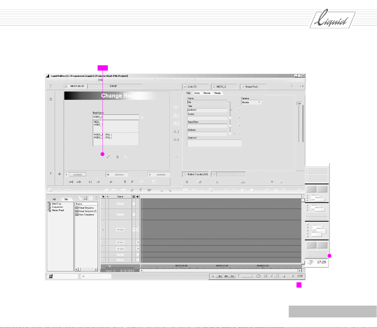
Step by Step
1 Insert your f irst tape and press F6 to start the Logging
To o l .
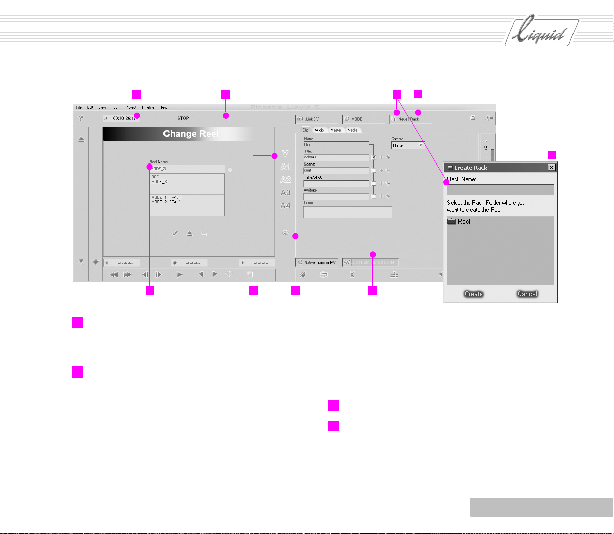
2 The top left-hand area contains the
- Timecode display - Indicates the player’s current TC position;
- Status field - STOP means the device with the tape is
ready for operation. DEVICE NOT READY means that
communication between the player and Pinnacle Liquid is
not operating. Is the device switched on and plugged in?
- Reel name dialog box. Enter a Reel name. You will not be
able to change this name later on.
3 Now enter a Rack, i.e. a “container” in which clips will be
stored.
Later on, you can distribute the clips to other Racks. At
this point, either select an existing Rack from the list
(click the field) or create a new Rack as follows: First
click the icon in this same field to open a dialog box, then
enter a name for the Rack and click Create.
4 You have selected the Reel and the Rack. Now check the
storage location that was specified for media files during
installation. To do so, rest the mouse pointer on the capa-
city indicator to display the directory path. Media files con-
tain the video and audio data for the clips.
Click the capacity indicator to display a list of possible
AV drives and directories (if any). For instructions on how
to configure a new drive or directory for digitizing AV
data, refer to the tip under “Alternative AV Drives/Directo-
ries” on page 3-18.
Note: Once all but 20 percent of your hard disk’s remain-
ing capacity has been used, be careful. The fuller the disk,
the lower the performance, especially if your hard disk is
highly fragmented. Also note that additional files may be
created during editing (for example, as a result of effect
rendering and functions such as Fuse and Consolidate).
Note: Every clip that you log and/or digitize is defined by
a Reel name, a clip Tim ecode-in and a clip TC-out. This
means that problems will arise if the same timecode (TC)
occurs more than once on a Reel. This can happen if the
TC counter returns to 00:00:00.00 several times (for
example, because you removed the tape). If you have a
tape like this: See “Tips” on page 3-16.
3 - 4
Chapter Recording AV
Page 48
PINNACLE
Timecode display Status field
62 2 3
Assign reel name
5 Select the Source tracks that you want to digitize. The
Source tracks can include one Video (V) and up to four
Audio (A) tracks on the tape.
6 Now you have to specify whether you want to log or digi-
tize the clips as Stereo or Mono.
Mono (symbol: One ring): One audio clip is generated for
A1 and one for A2. In Pinnacle Liquid, Mono clips are
always set to “Center” at the master audio output, meaning that they are played at the same volume on CH-1 and
CH-2.
Select rackCreate rack
3
3
Capacity indicatorStereo/MonoSource tracks
4652
Stereo (symbol: Two rings): A1 and A2 are written to one
audio clip. In Pinnacle Liquid, Stereo clips are always set
to left (A1 -> CH-1) and right (A2 -> CH-2) at the master
audio output.
Should you select Stereo or Mono? See “When to Digitize
As Stereo and When As Mono?” on page 3-20.
7 Is everything correct? Confirm the settings.
8 Now you’re ready to go: Press Play to start the tape. Use
the control buttons to cue up the tape to the Mark-in
point. The Mark-in is the start of the clip (or of the “take”,
“scene”, etc.).
Chapter Recording AV
3 - 5
Page 49

PINNACLE
9 Click the Mark-in symbol (or press A on the keyboard),
shuttle to the end of the scene (i.e. to the Mark-out) and
click the Mark-out symbol (or press
Naturally, you can also do this “on the fly”, meaning without stopping the tape.
The timecode values for the Mark-in and Mark-out are
retained and the clip length is calculated.
You can also edit all these fields. When two values are
known, the third is calculated automatically. For example,
click the field, enter a Mark-in, press
enter a length. The Mark-out is automatically set.
You can increase/reduce the values entered by pref ixing a
- (minus sign) or + (plus sign). For example, the Mark-in
is 00:01:00:00. Click the Mark-in field and enter
-00:00:15:00. The result is 00:00:45:00.
One more tip: You can use the TC information above the
video inlay as a “go-to” command. Enter the TC position
to which the player should cue up the tape and press
S on the keyboard).
ENTER or TAB and
ENTER. That will do it!
10 Particularly in the case of larger film projects, it may be
helpful for you to name clips and attach comments. This
is done on the Clip tab:
As long as you haven’t logged or finished digitizing the
clip, you can edit the text fields.
Use the mouse or
As soon as you press
player control mode; for example, you can start or stop
the player by pressing the
return to text input mode and to the Title text field.
TAB key to move from field to f ield.
ENTER, the keyboard returns to
SPACEBAR. Press TAB twice to
If the checkbox next to the field is activated, the text
entries are transferred to Clip Names.
Use the plus signs for numbering. Each time you click the
single plus sign, the number is incremented by one; clicking the double plus sign automatically increments each
new clip that you create by one. You can also edit names
and comments later on in the Clip Properties.
11 Now let’s take a look at the field for selecting the Media
Format. In the example, we’ve selected a Native Transfer,
i.e. a simple data transfer without format conversion. As
far as quality is concerned, there is no difference between
DV(dif) and DV(avi). If you’re exporting files to other
applications, you may be better off with *.avi because it’s
extremely common.
For details on the formats, see the Reference Manual.
12 You now have one clip and two options.
Log: If you click this option, the current clip is created in
the Rack but is not digitized. No Media file is created (not
yet).
You can digitize logged clips later on using Batch Digitize.
An exclamation point in a clip’s Picon indicates that there
is no Media Data for the clip.
Digitize: Click this button to digitize the current clip (the
player goes to the Mark-in and works up to the Mark-out)
and store the clip in the Rack.
Variation: Start the player. Click Digitize once (= Mark-
in), click again (= mark-out + place clip in the Rack), next
clip, etc. This is also called digitizing “on the fly”.
3 - 6
Chapter Recording AV
Page 50
PINNACLE
Control buttons Timecode fields DigitizeLog
68
Rewind
Forward
1 frame back
1 frame ahead
Mark-in
Mark-out
Play
Stop
Glossary: Digitize = Capture; this term originated back
when analog material actually was converted, which is
often still the case. Here, however, it generally refers to
the transfer to your system.
Batch Digitize: The entire tape (or tapes) is first logged
and then all the clips are automatically digitized.
Chapter Recording AV
Automatic (++) and manual
(+) clip numbering
Shuttle
The clip name is composed of the
10
entries in the text fields
See also “Methods: Log, Digitize All or Scene Detection?” on
page 3-21.
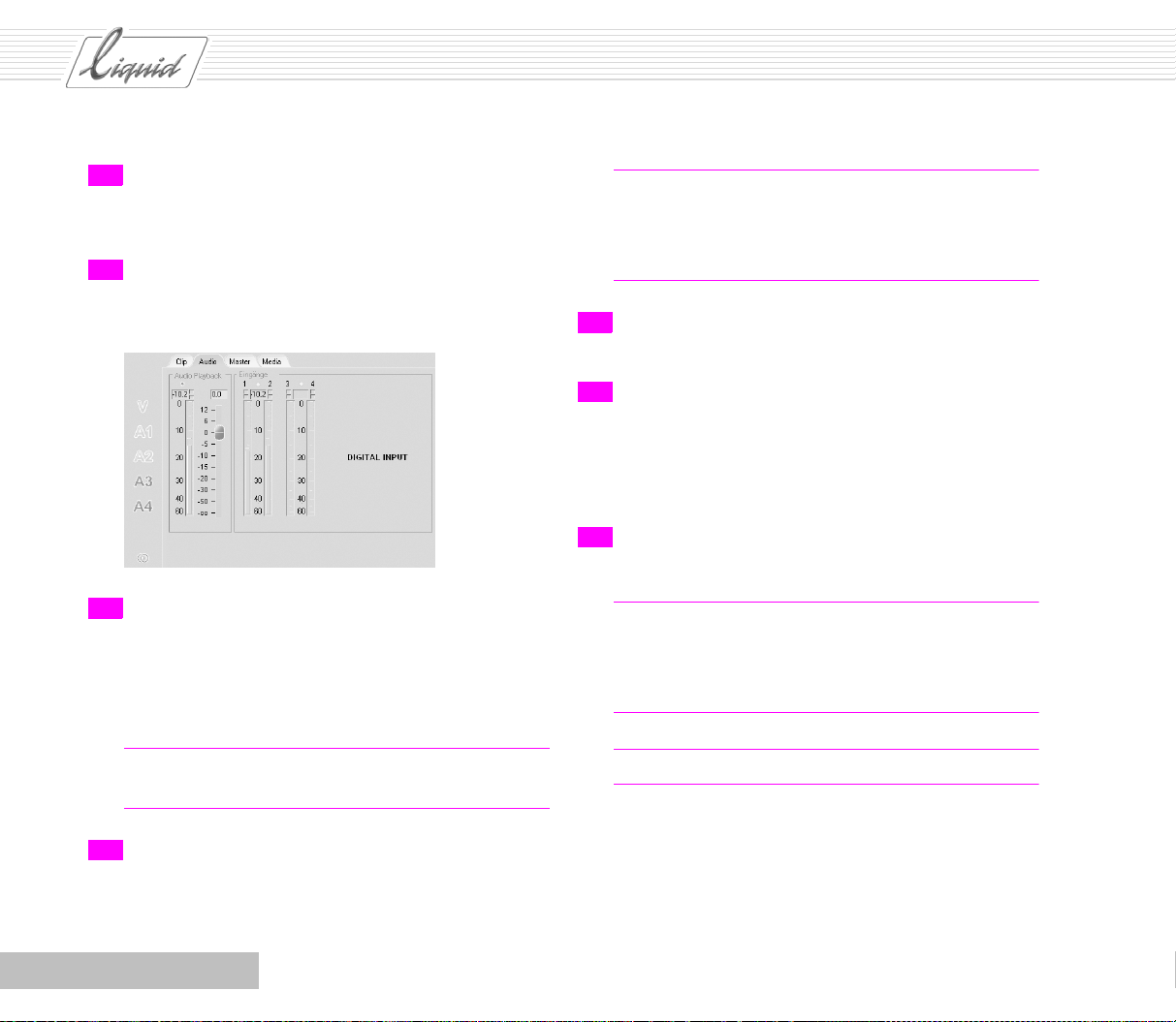
13 Play the tape again and go to the Audi o tab.
Here you can control the clip’s Audio Playback, i.e. the
volume at which this clip is played back on the Timeline.
14 To exit the Logging Tool, press ESC or click the Running
man (Exit button) in the upper right-hand corner.
3 - 7
Page 51

PINNACLE
You cannot control the level with Native Transfer (AVI, DIF) at
the input because, strictly speaking, DV does not involve digitizing via codec; instead, data is copied from a tape to the hard
disk.
If you have access to analog Audio Inputs, you can also adjust
the level at the input. This is termed “destructive” because the
data has already been modified when it is written to the hard
disk.
When is it worthwhile to use the fader for Audi o Playback ?
Whenever you notice during the logging or digitizing process
that the sound is louder or softer than it should be. For street
sound, you can go ahead and lower the level to -20 dB. An
interview that was recorded at too low a volume should be
increased to close to -9 dB. You can also readjust Audio Play-
back later on, clip by clip. If you’re working with the Picon
View in the Project Window or Project Browser, a blue star in the
Picon indicates that the volume was modified:
Clips with a modified
playback volume are
identified by a blue star
Glossary: Codec – Abbreviation for coder/decoder; often
refers to the method for encoding/decoding video and
audio (by means of hardware or software).
Media data - During the digitizing process, Media files are
generated and stored in media directories, i.e. saved in the
system. A clip can comprise multiple media files because
video and audio information is stored separately.
3 - 8
Chapter Recording AV
Page 52

Reset
max. dB
Max. dB
PINNACLE
Raise/lower dB
13
Audio tab
Exit the
Logging Tool
Chapter Recording AV
3 - 9
Page 53

PINNACLE
Plus ...
LIVE Player
You can also play back a video and/or audio signal live. “Live”
simply means that the playback source is not
controlled by Pin-
nacle Liquid.
When should you use live playback?
When the playback source cannot be controlled by the
software: Audio CD player, TV signal, DV player that is
not remote-controllable.
If the tape shows signs of numerous Time code problems (a
typical indication of this is when the error message “Preroll position could not be located” appears during digitizing).
And when should you not?
If you want to “batch” the clips later on (i.e. transfer them
to the AV disks using the Batch Digitize command). In this
case, you need a timecode referencing the tape.
In Pinnacle Liquid, the LIVE input is treated as a player but
without remote control. You can set its parameters under Player
Settings (select Pinnacle Liquid Menu Bar > Edit > Control
Panel > Site > etc.). Or, in the Logging Tool, click the player but-
ton above the Clip tab to enter the settings more directly.
However, the analog LIVE player also requires a Timeco de;
otherwise, digitizing clips with the Logging Tool would not be
possible.
Under Player Settings, select the Settings tab, click the plus sign
next to the LIVE entry and then click Options. Timecode source
now appears on the right. Double-click the value to display a
short menu:
Time of Day means that the current system time
(hour:minute:second) is used as a timecode, supplemented by frames. Of course, this time can only be as
accurate as the time that was set under Windows.
When you open the Logging Tool, the system clock
appears in the Timecode Field. You can then digitize at any
time.
Custom means you can enter a value in the Logging Tool in
the Timecode field above the video inlay (right-click and
start typing).
In this case, the following applies: Before digitizing, you must
click the Play button to start the TC counter and enable the
Digitize button.
Now start the playback source and click Digitize as soon as you
have the correct video or audio.
Click Digitize once again to stop the procedure. The clip is fin-
ished and is placed in the Rack.
Vide o: Take timecode from the DV source (no analog).
3 - 10
Chapter Recording AV
Page 54

PINNACLE
Player Settings Player button for
opening Player
Settings
Click here to
switch to LIVE
player
Doubleclick Timecode source
to open
timecode
options
Time of Day or Custom or Video?
With Custom, you can generate an ascending series of
individual Mark-ins or use the hour information to generate a sort of tape numbering (the pros generally set the
tape TC so that the tape number appears in the recorder or
in the TC display on the monitor. For example,
01:00:00:00 indicates the first tape and 08:00:00:00 the
Chapter Recording AV
eighth. In this case, the tape can’t run for more than one
hour or the hour will turn over.).
Time of Day is easy and convenient because you don’t
have to enter anything.
3 - 11
Page 55
PINNACLE
Analog IN
Depending on the product, you can also digitize analog audio
and video signals, either via the LIVE Input or controlled by
means of the RS 422 interface. However, it is not possible, for
example, to import via S-Video and simultaneously control the
player by means of i.Link DV.
If you want to switch to analog inputs, do the following:
1 Select Pinnacle Liquid Menu Bar > Edit > Control Panel >
Site or, in the Logging Tool, select
the player button to select a player.
Player Settings and click
2 Click LIVE and then Connections and select an analog
video input under Video In put; then select an analog audio
input (Ch1 - Ch2). If at all possible, use the YUV input or
the Y/C (S-Video) input to obtain the best quality. Otherwise use CVBS.
Glossary: Y/C is a video signal in which the luminance
and color signals are transmitted separately. It is often
called S-Video.
CVBS is an encoded TV signal.
YUV is a video signal used to transmit brightness and
color signals (two color difference signals) separately.
Also called component signal.
Two things have changed:
On the Audio tab, a “Destructive” adjustment is now also
possible.
Level meters and faders are available. This means that the
incoming signal is ingested at a higher or lower volume,
i.e. it is already modified when saved to the hard disks.
Tip: Make a Destructive adjustment only to the point
where there will be no risk of an overload or underload.
For a qualitative adjustment (for example, to reduce ambient sound), use the Audio Playback fader.
A Video Tool is provided for analog video.
You can use this tool to adjust Brightness, Contrast and
Saturation. The tool also has a “destructive” effect and
should therefore be used with caution.
3 Exit the dialog boxes, press F6 to open the Logging Tool (if
necessary) and select the LIVE player and a timecode
source (as described above).
3 - 12
Chapter Recording AV
Page 56

PINNACLE
Audio tab
Open Video ToolVideo Tool
Chapter Recording AV
3 - 13
Page 57

PINNACLE
Direct Insertion
“Normally”, you assemble your clips and then go to the Timeline (perhaps even via a storyboard) for the editing process. A
more direct way, however, is to digitize and immediately create
a raw cut using the Direct Insert button. Here’s how it’s done
(first an overview, then a few of the finer points):
1 If necessary, clear the Timeli ne by clicking New Sequence.
New sequence
2 In the New Sequence dialog box, you shouldn’t have to
change anything but the name if you already created a
Sequence with suitable values.
3 Open the Logging Tool (F6).
4 Enter the usual settings, such as Reel selection, Rack, Ste-
reo/Mono, etc.
5 Select an insertion mode, preferably Overwrite (red).
The Direct Insert button has three states:
Off – gray button
Insertion overwrites clips and gaps (Edit Style = Over-
write) – red button
Insertion shifts clips and gaps (Edit Style = Film Style) –
yellow button.
Click the button repeatedly to toggle between the three
states.
6 We recommend that you select the current Playline posi-
tion as the insertion points for new clips on the Timeline.
The Playline jumps to the end of each newly inserted clip.
This is the easiest and most convenient method for assembling a Sequence.
However, you can also set the Mark-in on the Timel ine.
7 Log or digitize the clips as usual. Each time the system
finishes logging and/or digitizing a clip, the clip is
inserted on the Timeline and in the current Rack.
Naturally, clips that were only logged cannot be played
back due to a lack of Media data. They still need to be
“batched”.
8 When the rough cut is finished, you can disband grouped
clips (if any) on the Timelin e. Select all the clips and, from
the shortcut menu for one of the clips, select the Disband
Clip(s) option. Whether or not they are Grouped depends
on the Mapping. For more information, see the next section.
3 - 14
Chapter Recording AV
Page 58

PINNACLE
Tracks and Mapping
Direct Insertion positions clips on the basis of Source track
labels, i.e. the (moveable) relationships V, A1, A2, etc. to the far
left in the Timeline header:
These Labels identify the specific Tr a ck s on which the clips
should be inserted and can be moved by means of the mouse.
Note that Tr a c k activation is also shifted along with the Label.
Also note that clips can be inserted on active Tra c k s only!
Open the settings for Mapping and activate those that you want.
Direct Insert
65
Mapping
Chapter Recording AV
Track label indicates position
3 - 15
Page 59

PINNACLE
Tips
This section contains a few tips, observations and instructions
for typical situations.
Tape Has Identical TCs
A tape that has identical timecodes, meaning a tape on which
the same TC ranges occur two or more times, poses a genuine
problem for editing.
Try to avoid this situation.
If possible, leave the tape in the camera until you’re finished recording on it. Use shorter tapes (this is also safer,
in case you should ever destroy or lose a tape).
Use the camcorder’s “Edit Search” or “End Search” function. The device then looks for the correct starting point.
For instructions on using this (or a similarly named) function, refer to the operating instructions provided by the
camera manufacturer.
Record on a “striped” tape, i.e. a tape with a continuous
TC. To make a striped tape, simply record the tape in the
camera with the lens cover closed and the audio
unplugged. Or select Pinnacle Liquid Menu Bar > File >
Record To Tape and then the Stripe Tape command.
But if you already have a tape with identical TCs:
Observe the timecode when Logging/digitizing. If there
are one or two resets to 00:00:00:00, simply define a new
Reel after
the reset (for example, Ibiza2004-2). Set the
first Mark-in after the reset, leaving an adequate gap - at
least 20 seconds!
Digitize LIVE, i.e. without player control and with a
System or Custom timecode. But please note: You cannot
edit these clips later on by means of Batch Digitize! (See
above for a description of LIVE digitizing.)
Copy the entire tape to the hard disk with a system or
custom timecode, copy it back from the Timeline to a tape
and then copy it back to the system, this time with a continuous TC. With DV, you don’t have to worry about lowering the quality. And with the new tape, you will also be
able to “batch”.
If you have a second device: Copy the problematic tape to
a tape with a continuous Timeco de.
3 - 16
Chapter Recording AV
Page 60

PINNACLE
Background
This timecode problem usually occurs when you remove a DV
tape from the camera and reinsert it or rewind and fast-forward
a DV tape in the camera. For most DV cameras, and especially
those in the consumer segment, this means that the timecode is
reset to 00:00:00:00. As a result, each time you restart recording you produce identical timecodes because at the breaks the
timecode is not seamlessly continued.
However, Pinnacle Liquid’s Media Management defines a clip
by means of a Mark-in/Mark-out and the Reel name.
For example, the Reel name is “Ibiza2004”. Let’s say you digitize a clip with Mark-in/out 00:02:00:00/00:02:30:00 and a
few more following the same pattern. Pinnacle Liquid creates
the appropriate media files.
Then the TC is reset and you continue digitizing over the exact
same timecode passages while the Reel is still named
“Ibiza2004”. What happens? You overwrite the media files
already created because Media Management assumes you’re
doing this deliberately - otherwise you would have created a
new Reel.
Nevertheless, this is not a Media Management problem but the
basis for a series of important Pinnacle Liquid functions. Also,
a tape with this type of TC resets is completely unsuitable for
Batch Digitize (Batch Capture) because it makes the unique
assignment of clips to tape positions virtually impossible.
Breaks in the Timecode
The second major problem encountered when digitizing is the
presence breaks or gaps in the TC. For example, if the TC’s
minute position changes from one frame to the next but should
not yet have done so if it were following the correct sequence,
digitizing is halted. Even entirely blank areas on the tape
(where the DV camera usually shows “blue” on the monitor)
throw off the digitizing process.
What should you do? Basically, follow the instructions above,
plus:
Leave wide margins around TC breaks on the tape. Do not
set a Mark-in right after a TC break because when Pinnacle Liquid shuttles to the Mark-in, it starts a little before it
(before = toward beginning of tape), creating the “preroll”. If a TC error is found between the start of a preroll
and the Mark-in, the following message is displayed:
“Preroll position could not be located”.
So if you do have to remove a tape, start recording again as
soon as you reinsert it and let it run for 20 to 30 seconds before
yelling “Action”.
Chapter Recording AV
3 - 17
Page 61

PINNACLE
Breaks in the Timecode (RS 422)
If controlled by means of RS 422: Select Pinnacle Liquid
Menu Bar > Edit > Control Panel > User > Logging/Batch Digitize to open the Logging Tool Properties dialog box. On the TC
Break Behavior tab, you will find the following options.
Alternative AV Drives/Directories
As hard disks become cheaper and larger, some users purchase
several mass storage units for their system from the very start.
Pinnacle Liquid can administer multiple digitizing drives and
allows you to change from one to another with the click of a
mouse - and Batch Digitize even does it automatically.
1 Select Pinnacle Liquid Menu Bar > Edit > Control Panel >
Site or, in the Logging Tool, click the AV, V or A symbol to
display the Media Management dialog box.
3 Define additional directories as follows:
Click Add and choose a new directory or select Create
New Folder.
4 Look at the column labeled P. The drive or directory with
the “X“ is the “primary” drive or directory currently
selected in the Logging Tool.
For Batch Digitize, this means the following: When the
primary drive is full, data is saved to the next suitable
drive in the list (provided this drive is not full and write
rights have been granted).
To access these settings, select Pinnacle Liquid Menu Bar
> Edit > Control Panel > User > Logging/Batch Digitize to
open the Logging Tool Properties dialog box and select the
Disk Full State tab.
Enter the time when the change should take place.
2 At least one directory already exists (created when Pinna-
cle Liquid was installed).
3 - 18
5 Assign write or read-only rights (right-click the setting in
the Access Rights field).
Chapter Recording AV
Page 62
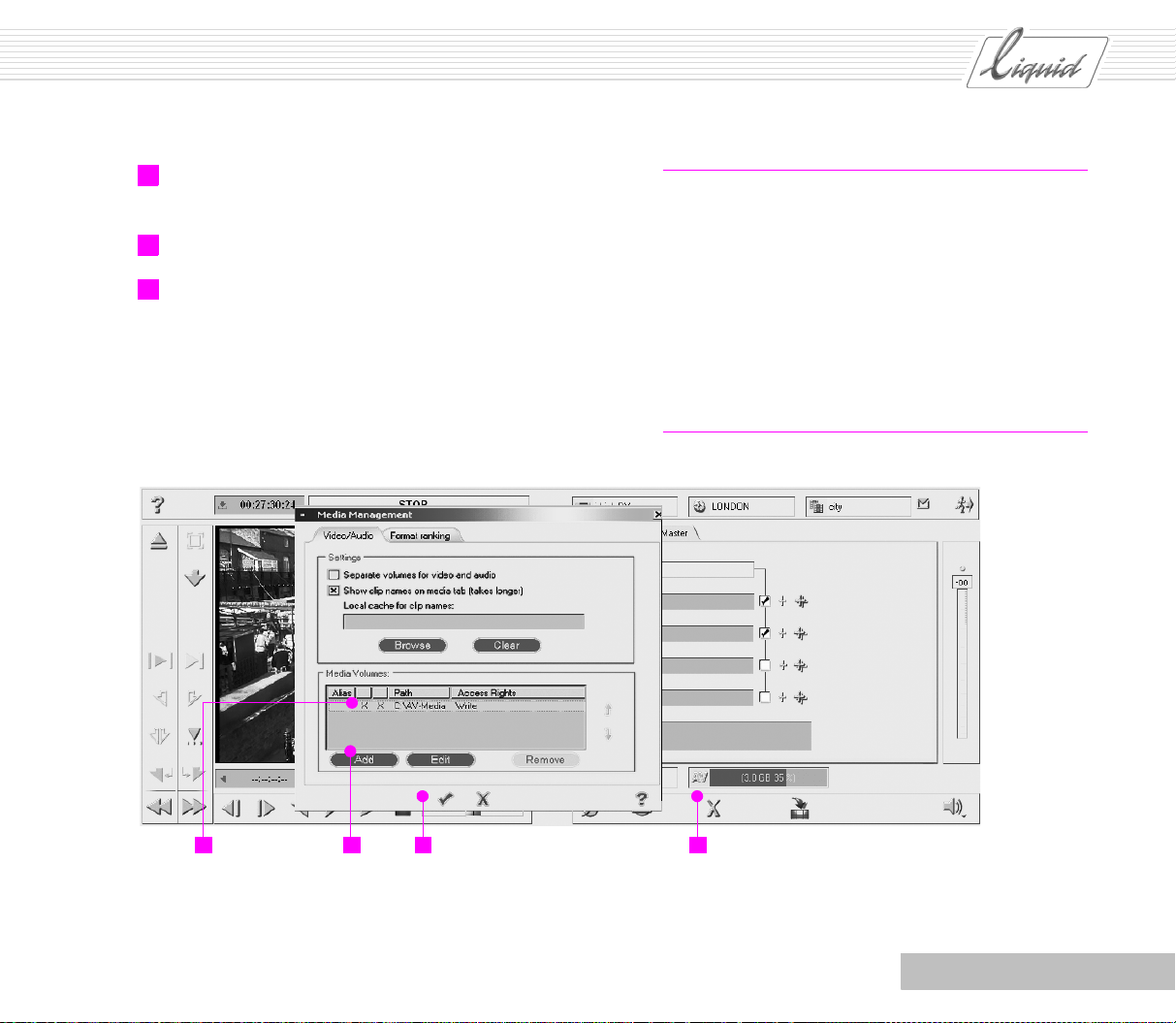
PINNACLE
6 If desired, right-click the Alias column and enter a plain-
text name, such as “RAID”.
7 Exit the Media Management dialog box.
8 In the Logging Tool, click the list of defined drives/directo-
ries (i.e. click the capacity indicator). If the current drive
is close to full, select a different one.
Note: When you installed Pinnacle Liquid, you already
defined a storage location for data you transfer to your
system You can look up the settings for the media drives
in the Media Management dialog box and modify them.
Although a hard disk is a high-capacity storage medium,
often one hard disk is not enough. “Drive” is a superordinate term for a data medium.
Many computers now have several hard disks installed;
Media Management Settings lets you administer these
drives.
x=Directory
selected
Add more
directories
Chapter Recording AV
2 14 3
Media Mgmt
dialog box
Click the AV symbol to open the
Media Management dialog box
3 - 19
Page 63

PINNACLE
When to Digitize As Stereo and When As Mono?
Basically, the following applies:
Each individual Stereo audio clip has a certain orientation
- either right or
Remember: A1 goes to the left and A2 to the right
speaker.
Mono audio clips are set to “Center”, which means they
are played at the same volume at both the left and
speakers. This applies to both A1 and A2. With Mono, you
adjust Panning .
Adapt the audio to the master you plan to use: A Stereo
master requires Stereo clips and a Mono master requires
Mono clips. Following this rule of thumb will make audio
editing much easier.
Stereo and Mono are clip Properties that can be assigned and
retained. In other words, the decisions you make in the Logging
To o l don’t have to be final...
Camera Microphone
Most consumer DV cameras have a built-in Stereo microphone
and record a Stereo signal. There is no reason not to digitize
this sound as Stereo.
left. With Stereo, you adjust the Balance.
right
Stereo/Mono
You will then be working with Stereo audio clips on the Timeline (one clip and two channels, i.e. “grouped”). The advantage
is that when you are editing the audio (for example, audio
fades), you can modify both Tra c k s simultaneously.
You can separate grouped Stereo audio clips into two individual
audio clips by means of the Disband Clip(s) option (in the
Timeline clip shortcut menu).
When output to DV, the audio is also recorded with the original
Stereo distribution (left/right).
External (Hand-Held) Microphone
When you use an external microphone (for example, for an
interview), the type of microphone makes a difference: Digitize a Mono microphone signal as single-channel Mono so that
the audio for the end product will be centered. The Stereo effect
of commercially available Stereo microphones is generally
poor. You can digitize it as Stereo but you will hardly be able to
detect any differences between the two signals.
3 - 20
Music from a CD
Stereo if the playback for the finished film is to be in Stereo and
Mono if the master is designed for Mono.
Chapter Recording AV
Page 64
PINNACLE
Methods: Log, Digitize All or Scene Detection?
Let’s get one thing straight: The best method is the one that
rids you of all unsuccessful takes as quickly and securely as
possible so that when you edit, you really do have a choice and
don’t have to make your way through loads of superfluous
clips. Of course, if you shoot perfect tapes you can ignore this
remark. But not even the pros shoot perfect tapes. Let’s briefly
weigh the pros and cons of the various methods:
Log, then Batch Digitize
Method: You view the tape, define clips by Mark-ins and
Mark-outs and combine them in a Rack.
Pros: Doesn’t generate any media files, requires no space
on the AV hard disk; can later be loaded to the system
automatically by means of Batch Digitize; you log only
what is useful. The method used by the pros.
Cons: Clips that have only been logged cannot be edited.
Log and Simultaneously Digitize
Method: Same as above but you digitize each clip.
Pros: Concentrated sifting through material, clips are then
immediately editable (particularly with the Direct Inser-
tion function on the Timeline).
Cons: Player has to keep returning to a Mark-in point;
time-consuming procedure.
Digitize Entire Tape, Then Generate Subclips
Method: You start the tape and digitize it to the end. You then
generate subclips in the Clip Viewer.
Pros: You can practically digitize the material in real time;
the player doesn’t have to shuttle back and forth; faster
non-linear access to the clip in the Clip or Source Viewer.
Cons: May require lots of disk space; unwanted material
is also digitized.
Automatic Scene Detection
Yo u u s e Automatic Scene Detection in the Pinnacle Liquid Logging Tool. See “Automatic Scene Detection in the Logging Tool”
on page 3-22.
Pros: Each take is isolated by means of a DV timestamp
and copied; process is automatic.
Cons: May require lots of disk space; unwanted material
is not rejected.
Batch Digitize (Capture)
Batch Digitize (sometimes called Batch Capture) is to a certain
extent an expansion of the Logging Tool. It involves the auto-
matic processing and digitizing of a batch, preferably of a large
number of clips.
Only logged clips with a Mark-in/out and a defined Reel name
can be “batched”. The clip’s timecode information must be
derived from a tape. As long as you retain this data and the
Chapter Recording AV
3 - 21
Page 65

PINNACLE
original material, you can recreate old Sequences and Projects at
any time.
With Batch Digitize, the system controls the player and processes the batch Reel by Reel based on ascending Mark-ins. All
you need to do is change the tapes. The intelligent management of Handle Lengths minimizes the amount of shuttling
back and forth performed by the player.
Automatic Scene Detection in the Logging Tool
Naturally, using Automatic Scene Detection will mean less work
in the Logging Tool. Since the pros and cons have already been
discussed, this section will simply tell you how it’s done:
1 Your digital device must provide a timestamp (datestamp)
when you press the record button. If you’re not sure
whether it does, refer to the operating instructions for
your camera.
Glossary: Timestamp – In addition to the timecode, the
timestamp stores information on when the recording was
made.
4 Click the top right-hand corner to open the Menu and
select Properties.
Click here and
select Properties
5 Activate Scene detection for the Logging Tool as follows:
Click the triangle to open the General tab and find the Use
scene detection if available option (refers to the DV times-
tamp). Click to activate and select the Master clips option
with a Handle Length of 25 frames. Then click the check
mark to apply the settings.
2 Insert the tape and connect the camera via the DV input
(any available analog inputs cannot be used, even if the
device is controllable by means of RS 422).
3 Press F6 on your keyboard to open the Logging Tool and
select Reel, Rack, etc., as described above.
3 - 22
Chapter Recording AV
Page 66

PINNACLE
Triangle for opening the “General” tab
Activate scene detectionApply
6 Start playback at the desired point and click Digitize.
Although the user can’t see it initially, Pinnacle Liquid
starts logging each scene change.
Viewer. If you want to select another rack, position the
mouse pointer on the name of the selected Rack in the top
right-hand field. The mouse pointer changes to a triangle.
Click to open the list box.
Selected rack – click here to open the list box
Select another rack
Pinnacle Liquid provides another type of Scene detection in the
Clip Viewer that is based on the analysis of video content. See
“Automatic Scene Detection” on page 6-4.
7 Click Digitize once again to terminate Scene detection. All
the clips detected are now written to the selected Rack
where they can later be viewed and sorted using the Clip
Chapter Recording AV
3 - 23
Page 67

PINNACLE
3 - 24
Chapter Recording AV
Page 68
PINNACLE
1
Chapter
Storyboarding
General
Sometimes it’s useful to begin a larger Project by playing through the sequence of scenes on the Desktop and
arranging the material. Even clips that have not yet been digitized, including logged clips, are displayed as
Picons, allowing you to select the ones you want before digitizing. This lets you limit the amount of material to
be digitized beforehand and save storage space. But even if you’ve already digitized, Desktop storyboarding is a
good method for preparing the cut.
4
Page 69

PINNACLE
Step by Step
Before you begin, place about twenty clips in a Rack.
1 Using the View Switcher, open the second view from the
bottom, i.e. the Desktop with the Project Window.
The second view from the bottom shows the
Project Window on the desktop
Click the eye icon to select a view
2 On the left-hand side of the Project Window, select the
Rack containing the clips.
3 Change to Picon View.
In our example, some of the clips have an exclamation
point in the upper right-hand corner. These are clips that
have not yet been digitized. Later on, these clips will have
to be digitized as well, before you begin working with
them on the Timeline. The easiest way to do this is to open
the Rack shortcut menu and execute the Batch Digitize
command for all clips that have only been logged.
5 Select all the shortcuts on the Desktop either by holding
down the
by holding down the left mouse button and dragging a
selection frame over all the shortcuts. Selected objects
have a yellow border. Now right-click on one of the
selected objects to open the shortcut menu and select a
Picon View. In our example, we’ve selected Mark-In/Out
Medium. In this view, the clip is displayed with a picon of
the Mark-in and a picon of the Mark-out.
SHIFT key and clicking each one individually or
6 Minimize the Project Window to make more room for the
Shortcuts.
4 Using the mouse, drag the clips to the Desktop one by one.
When you drop them, they appear on the Desktop as
Shortcuts, as indicated by the small arrow in their lower
left-hand corner. Create shortcuts for all the clips in the
Rack.
4 - 2
Chapter Storyboarding
Page 70
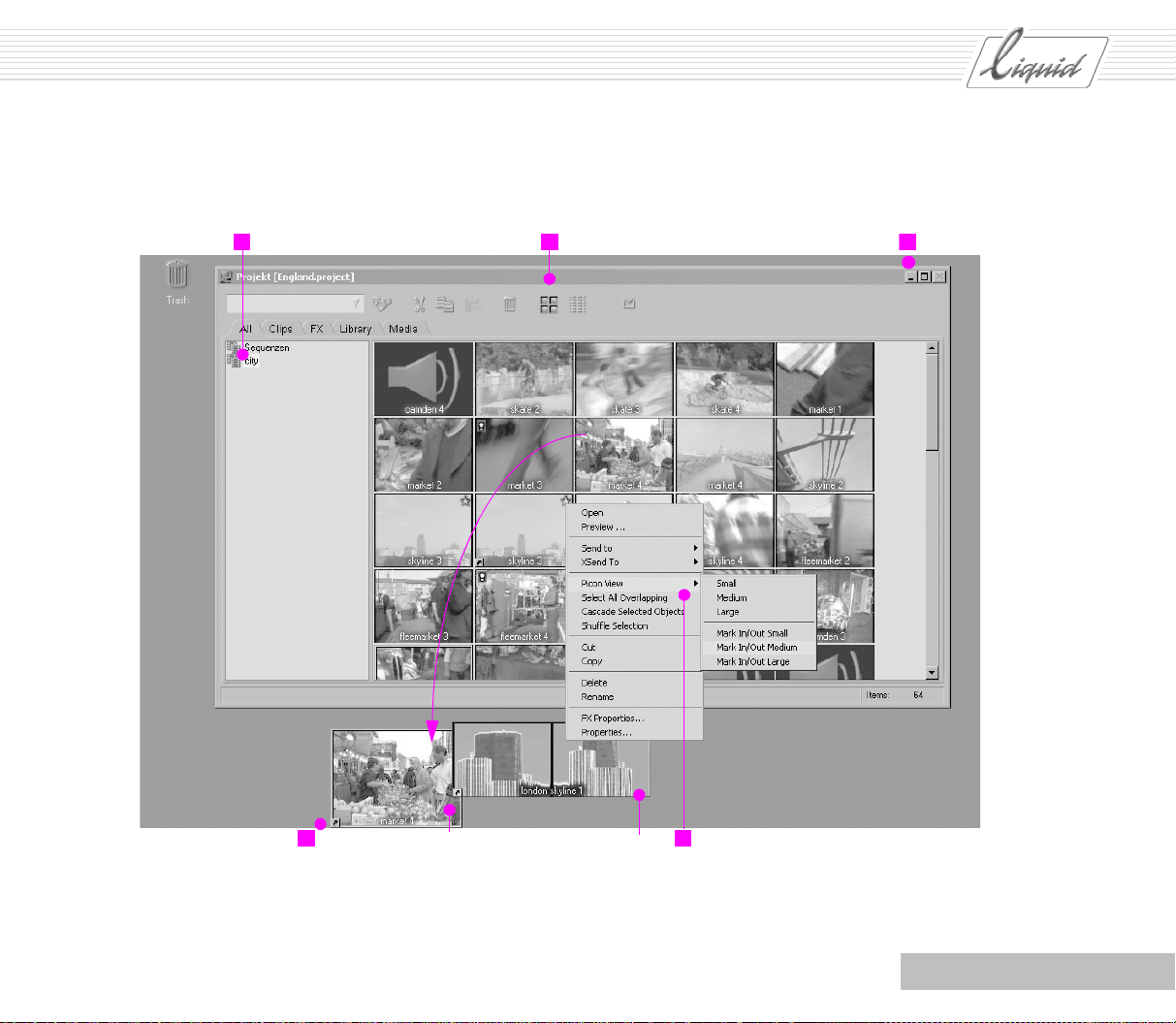
Holding down the mouse button, drag the clip from
the rack’s content area (on the right) to the desktop
PINNACLE
62 3
4 5
Chapter Storyboarding
Picon View: Medium or Mark-In/Out Medium
4 - 3
Page 71

PINNACLE
7 A lot can already be accomplished on the Desktop when
you select the Picon View displaying Mark-ins and Mark-
outs. This is because this view shows the frames of a clip
that are important for the montage. When you arrange the
clips in the correct order, you get a pretty good idea of
how the result will look later on.
The frames that will follow one another in the Sequence
are now directly adjacent to one another (if you disregard
the fact that some of this might be altered by trimming).
If you’re not sure which take is better, place them one
above the other between the interfacing clips and make
your decision.
Alternative clips positioned between interfacing clips
Glossary: Picons (picture icons) are miniaturized images
that help you identify the clip.
opens them in the Clip Viewer. If this doesn’t work, select
Pinnacle Liquid Menu Bar > Edit > Control Panel > User
to access the settings. Double-click Project to open the
Project Properties dialog box. In the Double Click On Clip
section, activate the Load Clip into Clip Viewer option.
Then confirm your entry.
9 Click the icon for your Project in the Taskbar to restore the
Project Window to its former size.
8 You can also view clips in this format by holding down
ALT key and double-clicking the clip. The clip is now
the
played back at this size while you also keep an eye on
adjacent clips (called Picon play).
In the default configuration, double-clicking the clips
4 - 4
Chapter Storyboarding
Page 72

PINNACLE
Click icon
Chapter Storyboarding
4 - 5
Page 73

PINNACLE
10 Are your clips now in the correct order? You need to
make a little room on the Desktop. While holding down
the
SHIFT key, select the clips in the order they should
later appear on the Timeline . Then right-click to open the
shortcut menu and select Cascade Selected Objects.
11 The Shuffle Selection function will give you an idea of how
the results will look later on.
Make sure that all the clips are still selected (if not, hold
down the mouse button and drag a selection frame over
the Shortcuts so they are all contained inside it).
Drag frame around all
the clips
Right-click to reopen the shortcut menu and select Shuffle
Selection. The order in which the clips were arranged or
selected on the Desktop determines the order of the
Sequence. Nevertheless, they are shuffled from top to bot-
tom, i.e. in reverse order.
12 If any of the clips are not digitized, you must Batch digi-
tize these clips before you start working with them on the
Timeline, i.e. digitize all of them at once in a batch opera-
tion. See also “Methods: Log, Digitize All or Scene Detection?” on page 3-21.
Ideally, all non-digitized clips are located in one Rack.
Right-click an empty spot in the Rack content area (right
side of the Project Window) to open the Rack Shortcut
menu.
13 Select Batch Digitize > Clips Not Yet Digitized to digitize
all the clips in the Rack that have not yet been digitized
Or you can select the relevant clips ahead of time (by
holding down the
click an empty spot in the Rack content area to open the
shortcut menu and select Batch Digitize > Selected.
SHIFT key and clicking them all), right-
4 - 6
Chapter Storyboarding
Page 74

PINNACLE
Click here to open the
shortcut menu
... or Right-click an empty spot
to open the shortcut menu
Chapter Storyboarding
4 - 7
Page 75

PINNACLE
14 The Batch Digitize module contains a list of tasks to be
completed. Click the Digitize button to start the process.
A safety prompt asks you whether the correct tape is in
the player. If everything is correct, click the checkmark to
confirm. While your computer is working, a progress
indicator appears below the list. As soon as all the entries
in the list have been processed, the window closes automatically.
Digitize
15 You can also send the storyboard directly to the Time line.
Even if you don’t see it, the clips pass through the Clip
Viewer. This means that the same rules that we have
already encountered numerous times before apply to the
Tr a c k s : The destination Tr a c k or Tr a c k s must be high-
lighted, i.e. they must not be Deactivated or Protected.
Let’s change views so we can prepare the Time line for the
clip transfer.
The bottom view shows the Sequence
Editor and Timeline
Click the eye icon to select a view
16 For simplicity’s sake, let Pinnacle Liquid select the Tr a c k s
once again by activating the Mappings Enabled option in
the Source track mapping menu (checkmark visible). In the
example, the other options are deactivated (no checkmark). In the case of Grouped, this means that audio and
video are positioned on separate Tr a c k s . Because Stereo
mappings separate is deactivated, Stereo audio is posi-
tioned on a single Tr a c k .
4 - 8
Chapter Storyboarding
Page 76
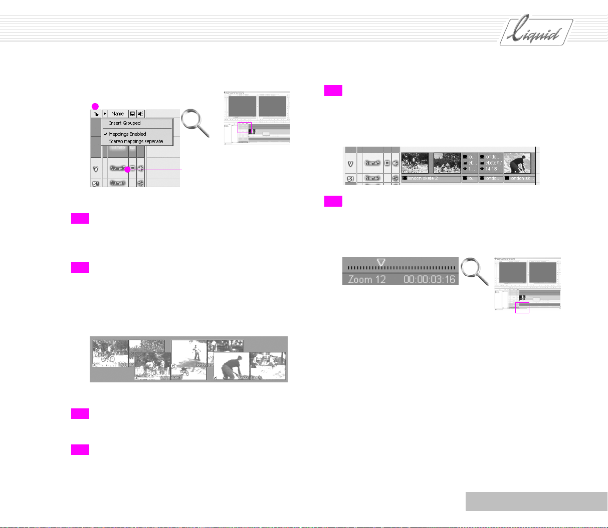
PINNACLE
Click here to open source track
mapping menu
The corresponding tracks
must be highlighted
17 Click the eye icon once again and select the second option
from the bottom to reopen the Desktop with the Project
Window.
18 For the example, let’s limit ourselves to different takes of
one scene. Select them one by one in the order in which
the clips should appear on the Time line. If you overlap the
clips slightly, the order will be easier to see.
21 Yo u r Timeline should now resemble the one shown. As
was to be expected, the first clip (on the left side of the
desktop) also appears first on the Tim eline.
22 If you can’t see all the clips on the screen, use the Zoom
Control to adjust the Tim eline scale so that all the clips are
visible.
Left clip on the bottom, right clip on top
19 Right-click to open the shortcut menu and select Send To
> Timeline.
20 Once again, you need to change views to see the Timeline .
Click the eye icon and select the bottom view.
Chapter Storyboarding
4 - 9
Page 77

PINNACLE
4 - 10
Chapter Storyboarding
Page 78

PINNACLE
Chapter
Edit
Contents
Introduction ..................................................................................................................5-2
Single-Track versus A/B Editing................................................................................... 5-2
The Logical Sequence for Editing ................................................................................. 5-3
General .........................................................................................................................5-3
What You Need ......................................................................................................... 5-4
Step by Step ..................................................................................................................5-5
Drag & Drop ............................................................................................................. 5-5
Source Viewer........................................................................................................... 5-10
Trim Editor............................................................................................................... 5-13
Trimming Transitions ................................................................................................. 5-16
Three-Point Editing ................................................................................................... 5-17
Plus ... .........................................................................................................................5-22
Linear Timewarp........................................................................................................ 5-22
Generating a Still with a Snapshot............................................................................... 5-26
Multilayering............................................................................................................ 5-27
Containers................................................................................................................ 5-30
Multicam Editing....................................................................................................... 5-34
Tips .............................................................................................................................5-38
When Should You Use Which Method? .......................................................................... 5-38
5
Page 79

PINNACLE
Introduction
Single-Track versus A/B Editing
Let’s start with some basic information on Edits and how they
relate to the use of Tr a c k s in Pinnacle Liquid. The type of Edit
used in Pinnacle Liquid is called a “single-track edit”.
Outgoing Clip Incoming clipTransition
Single-track edit
Particularly if you use multiple Tra c k s , you will appreciate how
Pinnacle Liquid compactly accommodates many objects on a
single Tra c k
Glossary: Tr a n s i t i o n – In its simplest form, this refers to a
transition from one clip to the next. For the duration of the
Transition, a little of both clips is visible.
Single-track editing – When an edit has a Tra n s it i o n, the
Outgoing clip, Incoming clip and
tioned on one Tra c k .
A/B edit – When an Edit has a Tra n s i t i o n , the Outgoing
clip, Incoming clip and Transition are positioned on differ-
ent Tr a c k s .
Tr an s i t i o n are all posi-
For many people, single-track editing seems the obvious
choice. But for those of you who have worked with other systems that use A/B editing, the advantages may not be immediately clear.
Outgoing clip
Transition
Incoming clip
A/B edit
Leeway
There is one important matter that needs mentioning right
from the start – enough leeway. In Tr an s i ti o n s , two clips overlap and during this transitional period, you need material to
serve as a sort of postroll and preroll.
With A/B editing, this overlap is represented by a distribution
on different Tr a c k s ; in Pinnacle Liquid, on the other hand, the
overlapping area is integrated in the Tr a n s i t i o n because the
Incoming clip already begins at the start of the Transition and
the Outgoing clip doesn’t end until the end of the Tra n s i t i o n . All
that really matters, however, is whether a clip has enough
material; if not, Pinnacle Liquid displays part of the Tra n s i t i o n
in red. But this is easy to remedy because Pinnacle Liquid lets
you trim both the clips and the Tra n s i t i o n directly on the
Timeline .
5 - 2
Chapter Edit
Page 80

PINNACLE
The Logical Sequence for Editing
Just as you must frame a house before you can finish the interior, several rules of thumb apply to the Sequence of steps
applied in video editing.
Rough editing
Fine editing
Effects
Audio editing
The progression from rough editing to fine editing needs no
explanation.
General
You have digitized your clips and have already inserted several
clips on the Time line. Now you want to trim these clips so that
the Edits will be positioned in the correct locations. Especially
in the case of fast-moving images, you will need to be precise
down to the exact frame. You will need to avoid hard transitions in the audio and you will also want to set the exact length
and position of Tr a n s i t i o n s . As in most of the modules,
Pinnacle Liquid offers different methods for arriving at the
same goal that suit any working conditions. You can also combine methods and, once you’re familiar with the basic techniques introduced here, you will be able to master more
complex montages.
It is important that you do the audio work before applying
effects because many effects also influence the audio track(s).
Particularly when there are different takes for a scene, all the
audio should always originate from a single take. Decide
beforehand whether an audio clip should continue as ambient
sound throughout the entire Sequence or whether audio should
continue at points where the associated video material is being
cut.
Apply the effects at the very end.
When you follow this Sequence, the steps not only progress
from the bigger picture to the smaller details but also save you
time. If a Project’s basic structure is right, you won’t have any
unnecessary trouble with the details.
Note: This tutorial describes only one of several possible
ways to reach the goal. For optimal Editing - i.e. editing
tailored to your own needs - we recommend that you read
the Reference Manual (“Edit” chapter).
Chapter Edit
5 - 3
Page 81

PINNACLE
What You Need
You will need clips (including their Media data), meaning
video and audio files located on one of your system’s AV h ar d
disks and representing “media online”. For information on creating clips: See “Recording AV” on page 3-1.
You should already have your clips in the Project, either in one
or more Racks or on the desktop.
The Timel ine should be prominently displayed unless, for some
reason, the Project only view was selected for your desktop.
In this case, click the eye icon (on the bottom right in the taskbar) and select a combination view of the Timeline and
Sequence Viewer.
Then, if necessary, open the Project Browser by clicking the
button located to the far left above the start of the Timeline .
While the Project Browser is open, this button is highlighted in
yellow.
Open the Project Browser
Your screen should then look something like this:
Source Viewer (player) Master Viewer (recorder)
Project Browser Timeline
If you work with two monitors, select a view with the Project
Window and Sequence Editor and simply perform the steps
described below in the Project Window instead of the Project
Browser.
Dual monitor
operation:
Left - Project Window;
right - Sequence Editor
5 - 4
Chapter Edit
Page 82

Step by Step
PINNACLE
This section introduces several methods for inserting and trimming clips on the Timeline. You can also combine these methods, and it will be beneficial to select one or the other,
depending on the particular situation. See “When Should You
Use Which Method? ” on page 5-38.
Drag & Drop
1 Using the mouse, drag any clip from the Rack to the Time-
line (for example, Name5). The clip should not be too
long but must contain audio.
This method is called “drag & drop”: Click the clip to
select it, hold down the left mouse button, drag the clip to
the desired location and drop it.
2 Important: The Tra c k you select must be activated for
Video and Audio Play back . Click in the field to activate or
deactivate Playback.
When you use drag & drop to insert a clip on the Time-
line, it is always inserted as one
contains one, two, or more Audio Track s. We’ll deal with
audio later on.
object, even if the clip
Note: When you drop clips onto different timeline tracks,
the highest-level clip has priority; i.e. it is superimposed
on the clip(s) below it. See “Multilayering” on page 5-27.
3 Before dragging the next clip, set the Timelin e scale so
that you can see the end of the first clip you inserted. To
do so, use the
keyboard or drag the Zoom Control slider.
Chapter Edit
ARROW UP and ARROW DOWN keys on your
5 - 5
Page 83
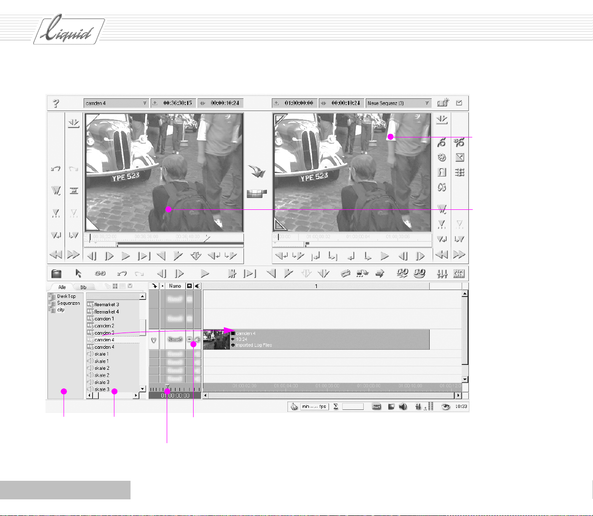
PINNACLE
Master
Viewer
Source
Viewer
Project Browser – Racks
and folders on the left,
contents of a rack or
folder on the right
5 - 6
Activates video and audio playback
Zoom control
Chapter Edit
Page 84

PINNACLE
4 Now select the next clip and drag it to a position just after
the end of the first clip (clip-out). The “magnet symbol”
appears. If you don’t see the magnet, press the
As the clip nears the position, it suddenly snaps to the
clip-out of the first clip.
You have just made a hard cut. Two clips already make up
a Sequence.
You can forget about “A/B editing” as well as reserved
“effect tracks”, “video tracks” and “audio tracks”. In Pinnacle Liquid, you connect a clip to a clip to a clip.
Glossary: Magnetism is a timeline property that can be
configured in the Timeline Properties dialog box. To open
this dialog box, select Pinnacle Liquid Menu Bar > Edit >
Control Panel. Double click Timeline and change to the
General tab.
SHIFT key.
5 The red vertical line on the Timelin e is called the Playline.
It identifies the position of the frame that is currently visible in the Master Viewer (the “recorder window”).
6 An editor would now look at the cut and might want to
revise it. In this case, the Playline must be positioned
“before” the cut. “Before” always means toward the
beginning of the Timeli ne and “after” means toward the
end of the Timelin e.
You now have several options:
Press the
SHIFT key to shift the Playline in increments of 10 frames.
Click the Timecode bar. The Playline jumps to the location
where you clicked:
“Scrub”: Hold down the left mouse button and drag the
mouse pointer back and forth across the frame in the
Master Viewer. The Playline follows your movement, both
below the Timeline and on the position bar below the
Master Viewer.
ARROW RIGHT/LEFT key together with the
Chapter Edit
5 - 7
Page 85

PINNACLE
select clips on the Time line, which is a prerequisite for
trimming.
... hide the Project Browser from time to time so you’ll
have more room.
Timecode barPlayline
7 Move the Playline and click Play or press the SPACEBAR
on the keyboard. Pinnacle Liquid plays the first clip and
the Edit to the next clip.
8 Stop playback by pressing the SPACEBAR, clicking the
Playback button or clicking anywhere on the Timeco de
bar. If you don’t stop playback, it stops automatically at
the end of the last clip.
9 These two clips are sufficient for demonstrating the
basics of trimming. Trimming means modifying the
beginning and end of the clip, shifting Edits and moving
clips. This requires that you...
... in any case, activate Edit mode. The button shown must
be highlighted in yellow. In Edit mode, you can click and
Edit mode
Project Browser
... shift the Playline to the beginning of the Sequence (start
of the film), either as described above or instantly using
the button shown.
... check whether the button shown here between the
Source and Master Viewers contains a red box. If not, sin-
gle-click it.
Go to Start
Overwrite style
10 Move the mouse pointer to the start of the first clip and
click when the following symbol appears next to the
mouse pointer:
5 - 8
Chapter Edit
Page 86
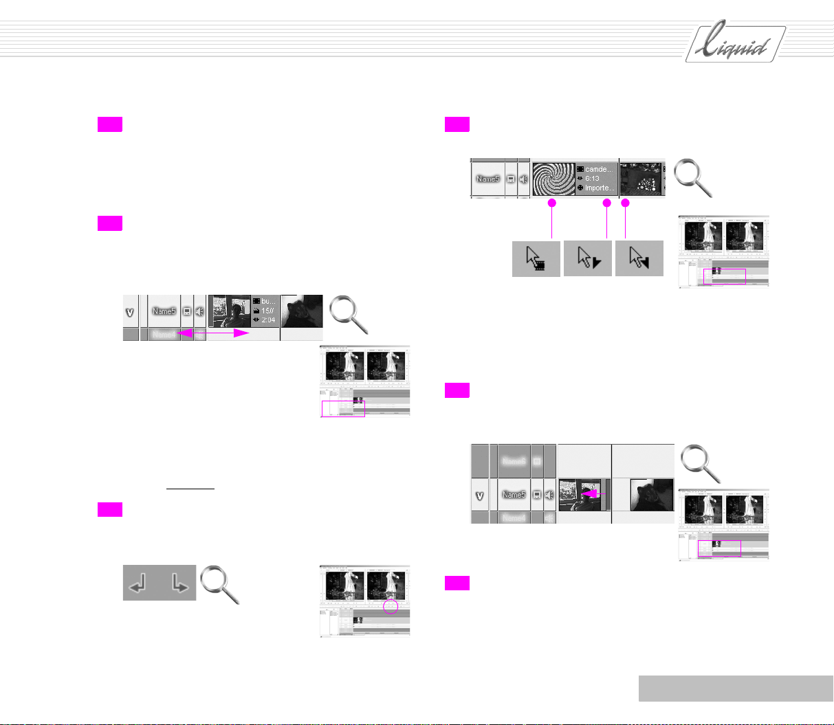
PINNACLE
11 The clip now has a red border, called a Handle. The sym-
bol represents a Mark-in. The Mark-in is the beginning of
the clip, i.e. the first frame. If the Mark-in turns red, this
means that it can now be edited. (It can also be yellow, but
we’ll discuss that later.)
12 Holding down the left mouse button, drag the red Handle.
What happens? You change the clip’s Mark-in. The
Master Viewer contains the frame that the clip would start
with if you now dropped the Handle.
You either lengthen or shorten the clip.
You also change the beginning of the Sequence relative to
the master timecode on the Timecode bar.
You are trimming
.
13 Select a suitable introductory frame and return to the first
Edit. Use the two buttons shown to pinpoint the Edit. The
Playline jumps to the first frame in the clip after the Edit.
14 Drag the mouse pointer around the Edit. The pointer
changes three times:
You can now trim the end (Mark-out) of the first clip or
the beginning (Mark-in) of the second clip.
You can also move whole clips; the Mark-in and Mark-out
remain the same.
15 Drag the Mark-out of the first clip toward the beginning
of the Tim eline . Notice what happens:
A gap opens up.
Chapter Edit
16 Run the Playline over the gap: The display in the Master
Viewer and TV monitor (if connected) is black. An empty
Timeline means “black”, i.e. a genuine black video signal.
This is important when you’re doing a fade-in or fade-out.
5 - 9
Page 87

PINNACLE
Source Viewer
Start over with an empty Sequence.
1 From the Project Browser, choose a clip that you want to
use to start your Sequence and right-click it to open the
shortcut menu. Select Send To > Source Viewer.
Note: If you work with the Source Viewer fairly fre-
quently, you should set it up so that a clip is sent to the
Source Viewer when you double-click it. Select Pinnacle
Liquid Menu Bar > Edit > Control Panel > User > Project
to open the dialog box and activate the Double Click On
Clip option.
Glossary: Source Viewer – Inlay on the left containing the
source material (Player); Master Viewer – Inlay on the
right containing the results of your work (Recorder).
2 In the Source Viewer, the clip appears on the left with two
hollow triangles, meaning that you are located at the Clip-
in. You will encounter this symbol again in the Master
Viewer.
3 Use the tool buttons to go to a position suitable for the
beginning and click Mark-In to set the clip’s starting
point. Go to a position suitable for the end or for an Edit
and click Mark-out to set the end point.
4 Select Play in to Out for the clip to view the results.
5 Make sure you’re working in Film Style – the Edit mode
represented by the yellow symbol between the viewers –
and click the Insert Arrow.
Plus: The destination Tr a c k or Tr a c k s must have a light
background, i.e. they must not be Deactivated or Protected.
The clip is inserted on the Tim eline and the Playline jumps
to a position one Frame after the end of the inserted clip.
Glossary: Film Style – In Film Style, clips already posi-
tioned on the Tr a c k are shifted over to the back when a
new clip is inserted.
Note: The Clip-in and Clip-out are identified by outlined
triangles and the Mark-in and Mark-out by filled triangles.
5 - 10
Note: You control the way in which clips are displayed on
the Timeline : Right-click in the Track header area to open
a shortcut menu and select the view. In our example, only
the Head (i.e. the beginning) is displayed.
Chapter Edit
Page 88

PINNACLE
Shortcut menu for
objects in
Project Browser
1
Chapter Edit
2
Source Viewer
5
3
5 - 11
Page 89

PINNACLE
6 Position two more clips on the Timeline by repeating
steps 1 to 5.
You have now generated two hard cuts and your Timeline
should look something like the one shown. If you can’t
see all the clips, adjust the Timeline scale using the
ARROW UP and ARROW DOWN keys on your keyboard or
by dragging the Zoom Control slider.
7 Using the Play In to Out command, you can now view the
entire Sequence with all three clips. This works even if you
still haven’t set any Mark-in or Mark-out points on the
Timeline .
9 (Re)activate the Edit mode. The button shown must be
highlighted in yellow. In Edit mode, you can click and
select clips on the Time line.
10 Use the two buttons shown to pinpoint the Edit. The Play-
line jumps to the first frame in the clip after the Edit.
11 Move the mouse pointer around the Edit. As in Overwrite
Style, it changes three times:
8 Stop playback by pressing the SPACEBAR, clicking the
Play In to Out button again or clicking anywhere on the
Timecode bar.
5 - 12
You can now trim the end (Mark-out) of the first clip or
the beginning (Mark-in) of the second clip.
Chapter Edit
Page 90
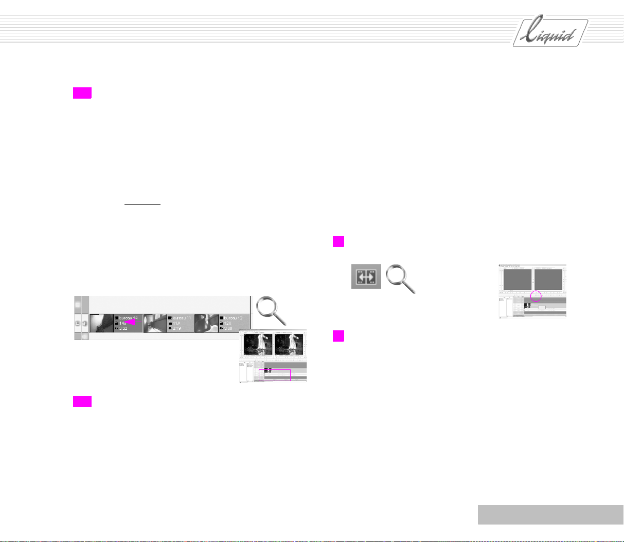
PINNACLE
12 Click the Mark-out of the first clip. The clip now has a
yellow border, called a Handle.
Hold down the left mouse button and drag the yellow
Handle. What happens?
You change the Mark-out. The Master Viewer contains the
frame that the clip would start with if you now dropped
the Handle.
You either lengthen or shorten the clip.
You are trimming
Drag the Mark of the f irst clip toward the beginning of the
Timeline.
Notice what happens:
In Film Style, no gap is created; instead, the subsequent
clip is shifted over.
.
13 Run the Playline over the interface to check the results.
Trim Editor
You have now learned two methods for inserting clips on the
Timeline and have learned about two Edit styles - Overwrite
Style and Film Style. This section introduces the Trim Editor,
which is a more precise method than the Handles.
In the example, we’ll continue working with the three clips on
the Timeline. When you work with the Trim Editor, it makes no
difference which Edit style is currently activated. Working with
the Trim Editor corresponds to working with Handles in Film
Style.
1 Click the tool button to open the Trim Editor.
2 If you aren’t already positioned on an Edit when you open
the Trim Editor, the Playline jumps to the next Edit and
uses yellow Handles to indicate that the clips are ready for
editing.
As with the methods already described above, the Tr a c k
must be active and unprotected when you work with the
Trim Editor.
For simplicity’s sake, we’ll stay with the example of a
Timeline with only one Tra c k . (We’ll deal with the special
features of edits across multiple Tr a c k s later on.)
When you open the Trim Editor, the last frame of the f irst
Chapter Edit
5 - 13
Page 91
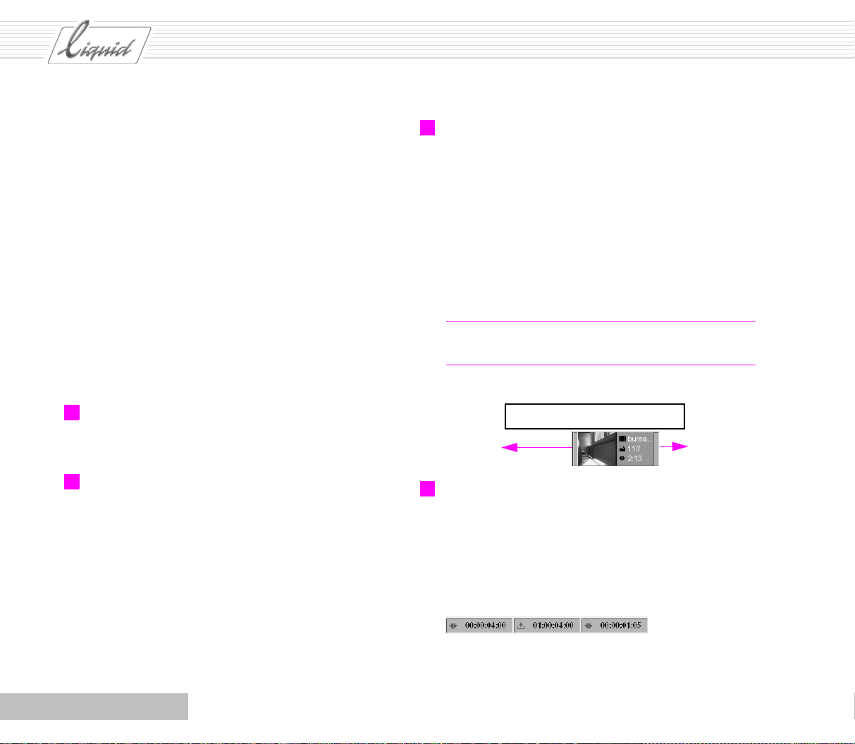
PINNACLE
clip appears on the left and the first frame of the second
clip on the right. Initially both clips are enabled for editing, as indicated by the dark gradient bars under the viewers and the yellow Handles already familiar from
trimming on the Timeline in Film Style.
Five tool buttons are located under the viewers that you
will need for fine editing.
The tool button on the far left moves the trim point back
ten frames. The next button moves the trim point back one
frame at a time. The middle button starts a Preview of the
Edit. In the default configuration, this preview shows the
Outgoing clip for one second and the Incoming clip for one
second.
The tool buttons on the right are the same as the first two
but move the trim point ahead one or ten frames.
3 To change the preview duration, select Menu > Prev iew
Range. In the dialog box displayed, enter a new value and
confirm.
4 Two timecode indicators are located next to the dark bars
below the viewers. They are set to zero when you open the
Trim Editor. These values refer to the frames at the Edit
and tell you in which direction and how far you have
moved the Edits. Click the Step back 10 frames button and
a value of -00:00:00:10 appears in both timecode indicators.
5 But sometimes you may not want to trim both clips simul-
taneously. In this case, simply click in one of the inlays.
The bar is then visible only under the activated viewer,
meaning that only this clip can now be trimmed. The tool
buttons now apply only to this clip. Also, to trim in both
directions the media file must contain enough leeway. See
“Leeway” on page 5-2.
You cannot move the Mark beyond the Clip-in. The buttons in the Tri m E di t or are disabled when you reach this
point.
Note: Click between the viewers to return to trimming
both clips.
Media file: clip-in to clip-out
Clip on Timeline: Mark-in
to Mark-out
6 In the example, we started by trimming two clips simulta-
neously. Now we’ll trim only the Outgoing clip. When you
trim, pay attention to the length of the clips; what good is
the most beautiful edit if you then discover that the clip is
too short? You also need leeway for the next edit. Read
the clip length above the viewer. A field in the middle
contains the Timecode position for the Edit.
5 - 14
Chapter Edit
Page 92

PINNACLE
Outgoing clip Incoming clipBars below viewers = Enabled for trimming
Menu
3
Tool
buttons
1
Chapter Edit
Yellow Handles
5 - 15
Page 93

PINNACLE
7 When you’ve found the correct position, start the Preview.
While the Preview plays the position in a loop, the tool
button is highlighted in yellow. Use this same button to
stop the Preview.
Preview
8 Go to the next Edit. It’s easy using the Go to previous Edit
and Go to Next Edit buttons.
In this way, you can work your way forward through the
Timeline , Edit by Edit.
Trimming Transitions
9 At the next Edit, exit the Trim Editor.
10 At this Edit, create a Cross fade using the following button.
11 Click the check mark to confirm.
5 - 16
12 The effect should now appear as a gray bar between the
clips. If the bar is not centered on the edit, this means
there is too little leeway or, more simply put, the clips
don’t overlap enough. In this case, you must trim the clips
Chapter Edit
Page 94

PINNACLE
and the effect until the effect has the desired length and is
completely gray. See “Leeway” on page 5-2.
13 You’re working in Film Style again so make sure the yel-
low symbol between the Source and Master Viewers is acti-
vated. If the red symbol indicating Overwrite Style is
activated, single-click the symbol.
14 You can also drag the clips and Tr an s i ti o n as usual using
the Handles and trim them. The Tr a n s i t i o n remains the
same; it retains its length and remains centered over the
Edit. Trim the clips and look at the results.
15 But in the same way, you can also trim the Transition
itself. Move the mouse pointer near the beginning or end
of the Tra n s i t i o n and notice that it changes just as it did
around the clips. You can trim the Tr a n s i t i o n exactly as
you did the clips. Left-click the end of the Tra n s i t i o n , hold
down the mouse button and drag the Tra n s i t i o n . In contrast to trimming clips, however, there is no yellow line.
Drag the end of the Tr a n s i t i o n toward the end of the Time-
line. You have now lengthened the Tr a n s i t i o n . You have
trimmed it.
Note: Once again, think about leeway. If there isn’t
enough leeway (i.e. if the Media file doesn’t cover the
entire length of the Tra n s it i o n), part of the Transition
appears red. When you drag a transition effect to the edit,
the tooltips let you know if too little leeway is available.
Three-Point Editing
Often you’ll reach a point where you’ve almost finished a
Sequence and suddenly find that you completely forgot a clip.
Or you’ve used a take that you liked and then notice that the
main character in this take has been cut. You now have another
take that you simply want to exchange for the one in the
(almost) finished Sequence. This is exactly what Three-point
editing is for. The three points refer to the Mark-in and Markout on the Timelin e plus the Mark-in or
the Source Viewer. The fourth point is calculated automatically.
It is also possible to leave a point on the Timelin e open. Finally,
note that you can also use the Clip Viewer instead of the Source
Viewer.
Mark-out of the clip in
Chapter Edit
5 - 17
Page 95
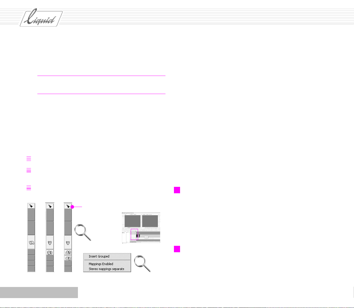
PINNACLE
Before moving on to the example, let’s talk a little bit about
Tr a c k s , Mapping and the general behavior of clips on the
Tr a c k s .
Glossary: Mapping – Indicates on which Tr a c k s the clip’s
Source tracks will be inserted.
Mapping is important when you insert clips on the Timeli ne
using the Send To > Timeline command from the clip shortcut
menu (right-click the clip to open its shortcut menu) and by
means of the Inser t Arrow. Suppose you have a clip comprising
one video Source track and one Stereo Source track.
When you insert it on the Timeline, you have three options for
grouping:
Group video and audio
Don’t group video/audio, group audio (Stereo mappings
separate unchecked)
Don’t group video and audio (Stereo mappings separate
checked)
Click to open shortcut menu
The result will be one Tr a c k in the first instance, two in the second and three in the third.
As a result of your selection, the corresponding Track labels
will appear in the Track header area and will show you where
the Source tracks are inserted. VA stands for Video/Audio
grouped, V for Video, S for Stereo and A for Audio.
Naturally, you can also ungroup Tr ac k s on the Timeli ne.
So what does Mapping have to do with insertion? Mapping
automatically activates the Track Label needed for the option
selected.
But even if Mapping is active you can activate or deactivate
Tr a c k s so that you can, for example, insert only video on the
Timeline even though the source Tra c k also contains audio.
Simply click the Names of the Tra c k s mapped for Audio to
deactivate them.
If Mapping is disabled you can insert gaps of defined length on
all activated Tr a c k s .
1 Insert a few clips on the Timel ine so that several Tr a c k s are
layered one above the other. One Tr a c k should be an Aud io
Tr a c k that runs throughout the entire Sequence without an
Edit. There should be one video Tr a c k with three consecu-
tive clips and two additional Audio Tracks with Edits that
are not in the same position as the Edit on the Video track.
Yo u r Timeli ne should look something like this.
5 - 18
Source Track Mapping menu
2 You want to replace the second clip with a different one
but without changing the other Tra ck s .
Use the Goto previous edit/Goto next edit command to go
to the Edit between the first and second clip.
Chapter Edit
Page 96
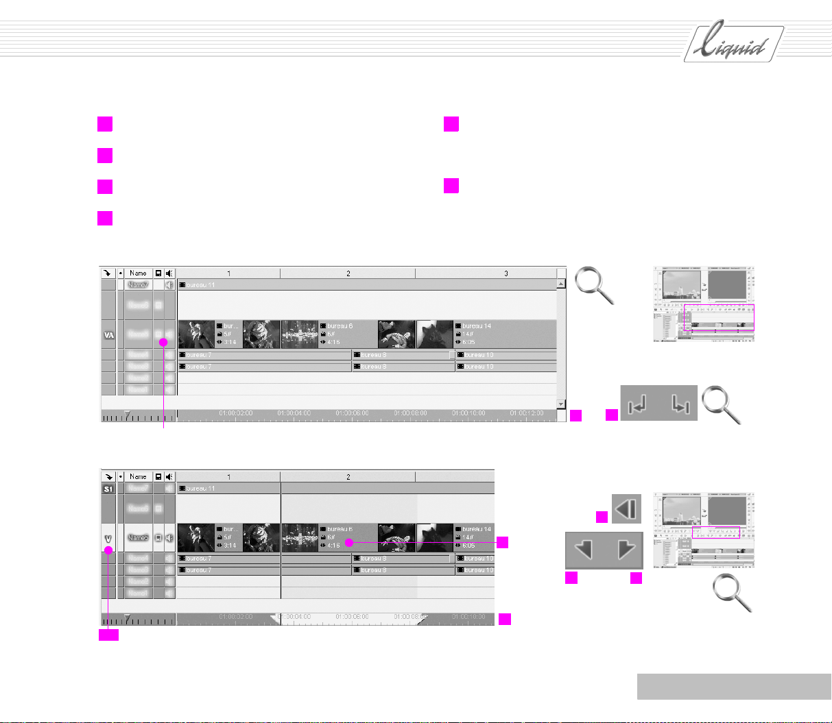
PINNACLE
3 Set a Mark-in.
4 Use the Goto next edit command to go to the next Edit.
5 Use the command 1Frame Back.
6 Set a Mark-out.
Important for playback: These symbols must be visible (active)
7 Yo u r Timeline should now look something like this. A
Mark-in and Mark-out on the Timecode bar indicate the
area to be replaced.
8 The area between the Edits is darkened. The length of the
clip you want to replace is indicated on this clip on the
Timeline . You need a new clip with at least this length.
2
1
5
Only this track is active
11
Chapter Edit
8
7
Clip
length
3
6
5 - 19
Page 97

PINNACLE
9 Click the button to open the Project Browser and select the
clip that you want to insert. Right-click the clip to open
the shortcut menu and select Send To > Source Viewer.
10 Now read the clip length in the Timecode field on the
right. Set the clip’s Mark-in and check whether the length
shown in the Timecode field on the right is still enough.
Is everything OK
Length
9
Note: Track header highlighted = Track is active.
Glossary: Overwrite Style – Other objects on the Timeline
are replaced. Film Style – Other objects are shifted over. In
other programs this is called Insert Style or Insert Mode.
12 Click the Insert Arrow. The clip displayed in the Source
Viewer is inserted on the Timeline and replaces exactly the
segment that you wanted to exchange.
The Playline jumps to a position one frame after the
inserted clip; the Mark-in and Mark-out you set for the
insertion are automatically deleted.
Only this track is active
11 Now select Overwrite Mode as the Edit style; the red sym-
bol must appear between the viewers. And take a look at
the Tra ck he ad er for the Timeline. Only the Tr a c k on which
you want to insert the clip should be active. Deactivate the
other Tr a c k s by clicking the Labels or the Names in the
Track header area.
5 - 20
Note: Naturally, you can also use the method described
above to replace only part of a clip or any segment of the
sequence.
It’s easier to replace exactly one clip if you set a Mark-In
and Mark-Out. To do so, right-click the clip Slice to open
the shortcut menu and select the Set Mark In/Out for Edits
x > x option.
Chapter Edit
Page 98
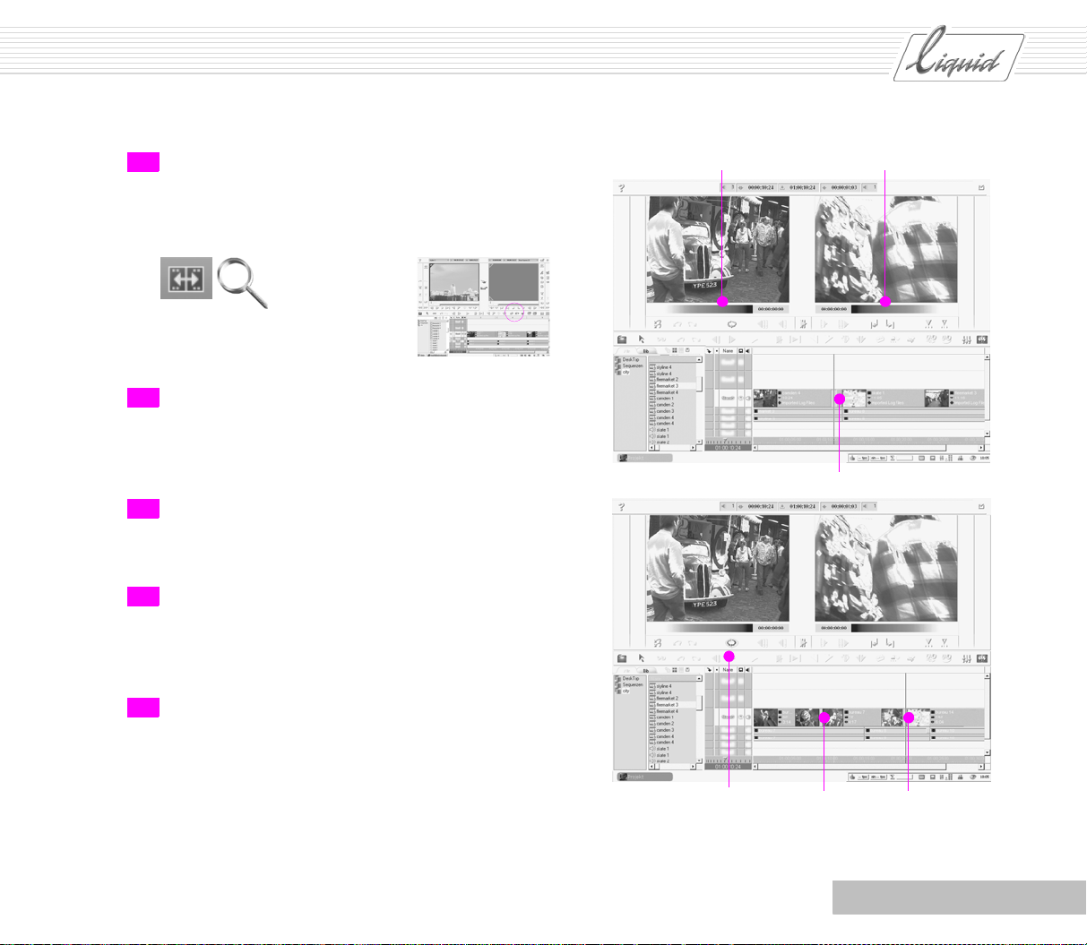
PINNACLE
13 Finally, you want to trim this clip a little as well but with-
out shifting the other clips on the Timeline . The Playline is
still located one frame after the inserted clip. Click the
tool button to open the Trim Editor.
14 First the Mark-Out of the Outgoing Clip and the Mark-In
of the Incoming Clip are selected. Yellow Handles appear
on the Timelin e at the corresponding locations. Gradient
bars are visible below both inlays.
15 Since you only want to trim the inserted clip, click in the
left-hand inlay. Now the bar is visible below the left-hand
inlay only.
16 You also want to trim the Mark-in and Mark-out at the
same time so click the Slip Clip button. The inserted clip
now has Handles at the Mark-in and Mark-out and you
can trim it using the buttons.
Bars below both inlays
Yellow Handles
17 When you’re finished, click the tool button once again to
exit the Trim Editor.
Chapter Edit
Slip Clip Yellow Handles
5 - 21
Page 99
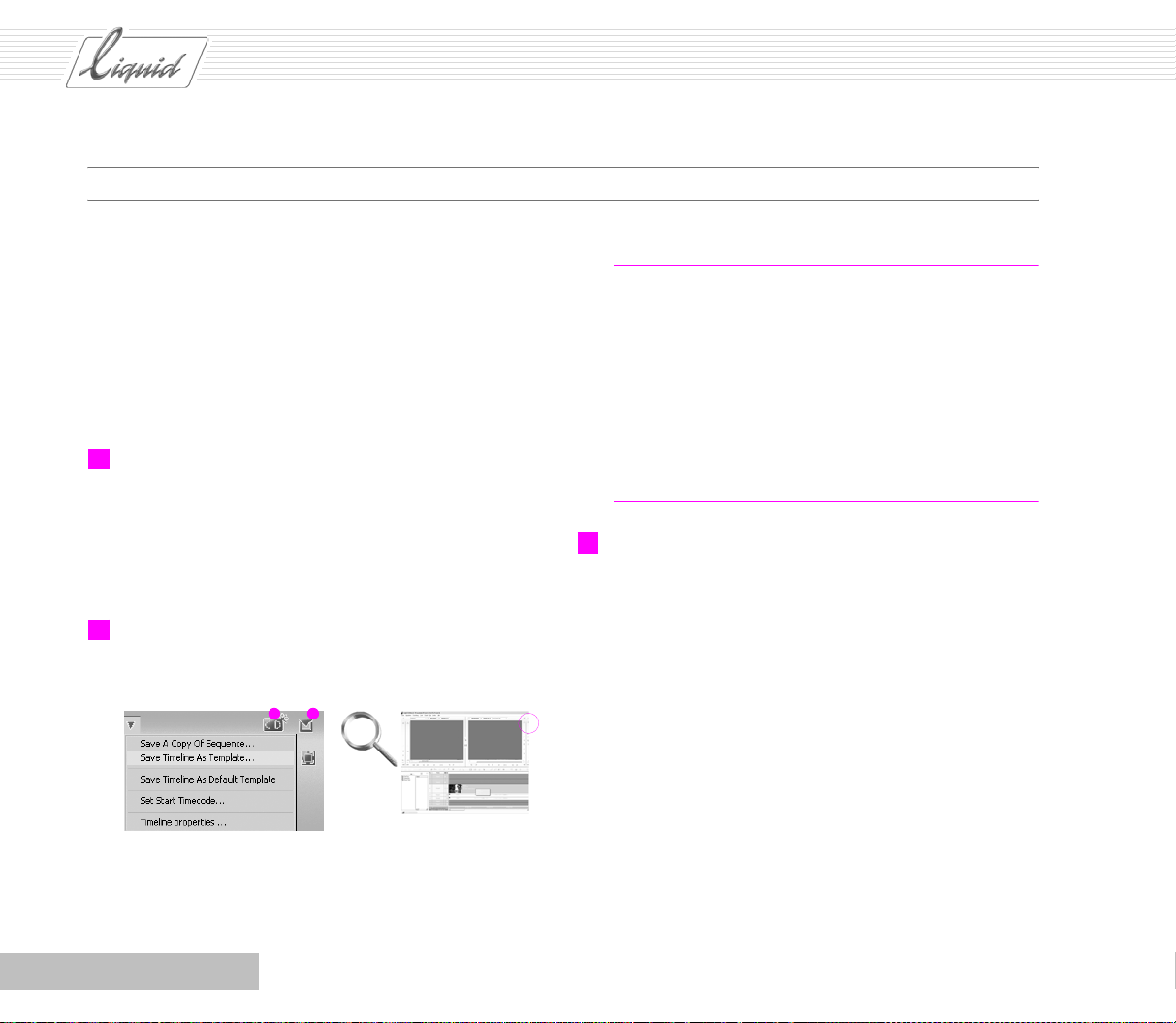
PINNACLE
Plus ...
Linear Timewarp
The previous section described one method for inserting clips
in gaps. Time warp effects enable you to adapt a clip when its
Mark-in and Mark-out would fit but would be too short.
Linear-Timewarp is mainly used for Slow Motion and Fast
Motion, here we show a Slow Motion in combination with the
Fit to Fill option.
1 Return to the view with the Timeli ne displayed on the bot-
tom and the Source and Master Viewers on top. You should
also reopen the Project Browser, in which you’ll need a
Rack containing at least three clips. Overwrite Style should
be activated as the Edit style, as indicated by the red sym-
bol between the two viewers
2 Click the New Sequence button to empty the Timelin e.
New sequence Open sequence menu
Note: Up until now, we’ve always used the Default Tem-
plate for the Timeli ne Layout. Once you’ve configured a
Timeline with your choices for the Tra ck He i gh t and View,
save it as a Tem p l a t e :
Open the Sequence menu and select Save Timeline As Tem-
plate. In the Save Timeline Template dialog box, enter a file
name and confirm by clicking Save. In the New Sequence
dialog box, you will now see the template you just named
listed in the Layout template field for selection.
3 One at a time, insert three clips on the Timeline (the clips
can be as little as five seconds long). First select a clip in
the Project Browser, then right-click it to display the short-
cut menu and select Send To > Timeline. Following inser-
tion, the Playline is positioned one frame after the inserted
clip. Use the same method to insert the other two clips on
the Timeline .
5 - 22
Chapter Edit
Page 100

3
Shortcut menu for objects
in the Project Browser
PINNACLE
Click to open menu
4
All options disabled in
the Source Track
Mapping menu
Only one video track is active
5 Yo u r Timeline should now look something like this.
4 Click the button in the column header to open the Source
Track Mapping menu. All the options in this menu should
be disabled (no check mark). Only the Tra c k with the V
for video should be active. If necessary, deactivate the
other Tra c k s by clicking them in the Track Header area.
Chapter Edit
6 Use the Zoom Control to adjust the Timeline scale so that
all the clips are visible.
5 - 23
 Loading...