

Page 1
T5/T5HO, T8 & LED AC-to-Grid Mount Installation .............. 2-3
T5/T5HO, T8 & LED AC-to-JB Mount Installation ................ 4-5
T5/T5HO, T8 & LED AC-to-ST Mount Installation ................ 6-7
T5/T5HO, T8 & LED AC-to-Fixture ................................... 8-10
T5/T5HO, T8 & LED PP-to-JB Mount Installation ............ 11-12
T5/T5HO, T8 & LED PP-to-ST Mount Installation ............ 13-14
T5/T5HO, T8 & LED PP-to-Fixture ................................. 15-17
T5/T5HO, T8 & LED Surface Mount Installation .............. 18-20
T5/T5HO, T8 & LED Wall Mount Installation ................... 21-23
Lens Detail ................................................................... 24-25
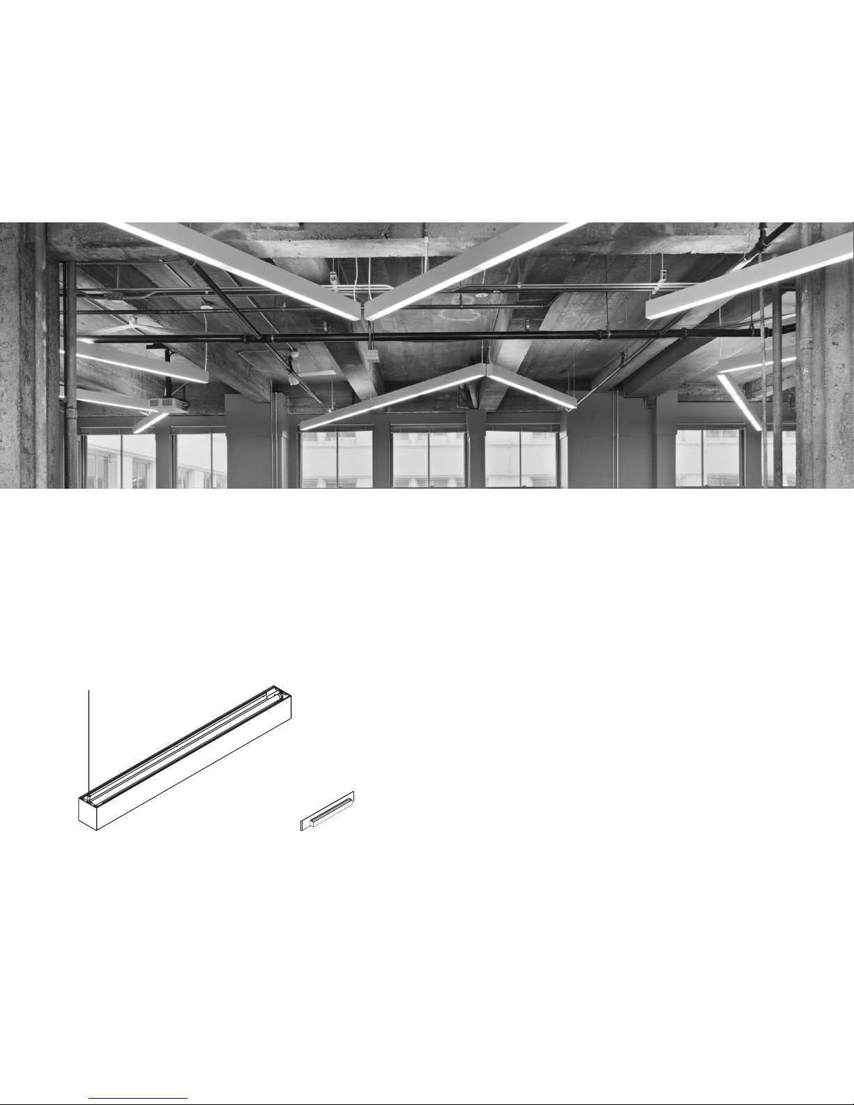
EDGE
EX33
EX44
INSTALLATION
INSTRUCTIONS
Page 2

EDGE
EX33
EX44
T5/T5HO, T8 & LED
AC-TO-GRID MOUNT INSTALLATION
Page 3
4 - Octagonal
Junction Box
5” Power Canopy
Strain Relief
18ga. SJT Cord
Cross-Bar
Conduit and Fittings
(by others)
1/4-20 Stud
#8 Junction
Box Screws
IDS Clip
Tie-Off to structure
2” Non-Power Canopy
Aircraft Cable
Coupler
Coupler
12655 E. 42nd Ave. #50 Denver, CO 80239 Phone: 303.322.5570 Fax: 303.322.5568 www.pinnacle-ltg.com
T5/T5HO/T8/LED
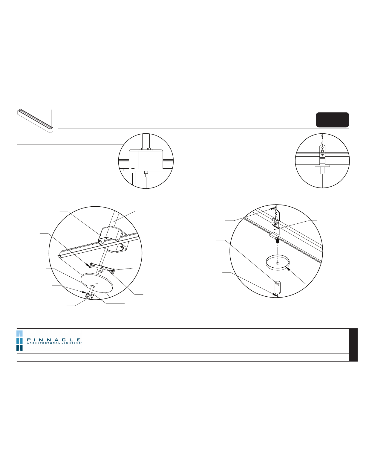
Step 2:
Non Power Mount
Step 1:
Power at Ceiling
1. Layout mounting/ junction box locations. Begin row
with fixture label at first mounting point.
2. Install junction box onto T-Bar ceiling. Tie box off to
structure. Install conduit from building power
3. Thread 1/4-20 stud to crossbar for power. mounts.
Install crossbar to junction box.
4. Run SJT cord through canopy, make necessary power
connections, secure using strain relief.
5. Feed aircraft cable through coupler.
6. Secure canopy to crossbar bolts using aircraft cable
coupler.
1. Install IDS clips for non-power mounts. Tie off to structure.
2. Feed aircraft cable through coupler.
3. Secure canopy to IDS clip using aircraft cable coupler.
AC - to - Grid Mount
EDGE
EX33
EX44
© 2017 Pinnacle Architectural Lighting
EdgeEX33_44_Booklet_January 2017
3 of 25
1. This product must be installed in accordance with applicable installation and electrical codes by a professional familiar with the
construction and operation of the product.
2. Minimum 90ºC supply conductors
3. All electrical connections must be performed by a certified electrician to applicable local and national electrical codes.
4. Fixtures must be mounted directly to structure.
5. The holding strength of AC cables cannot be guaranteed if the cables are damaged in any way.
Return to
Main Menu
AC cables with damage, bends, kinks, fraying, or knots must be discarded and replaced with new components. Never install a fixture where the AC cable is more than 5 degrees from perpendicular to the fixture. Fixtures are never to be raised by the cables (instead, lift the fixture up and adjust the cable position). Overtightening of hardware on grippers can damage AC cables. Never
exert force down onto the top of the fixture once it is hanging by safety cables. Never cut safety cables prior to installation. The first zip tie on the SJT and AC cables below the ceiling/canopy
must be no closer than 12” from the ceiling/canopy
Page 4

EDGE
EX33
EX44
T5/T5HO, T8 & LED
AC-TO-JB MOUNT INSTALLATION
Page 5
4 - Octagonal
Junction Box
(by others)
5
” Power Canopy
Strain Relief
18ga. SJT Cord
Cross-Bar
Conduit and Fittings
(by others)
1/4-20 Stud
#8 Junction
Box Screws
1/4-20 Stud
(by others)
2” Non-Power
Canopy
Aircraft Cable
Coupler
*
Stud sits 1/2”
Below Ceiling Plane
Coupler
12655 E. 42nd Ave. #50 Denver, CO 80239 Phone: 303.322.5570 Fax: 303.322.5568 www.pinnacle-ltg.com
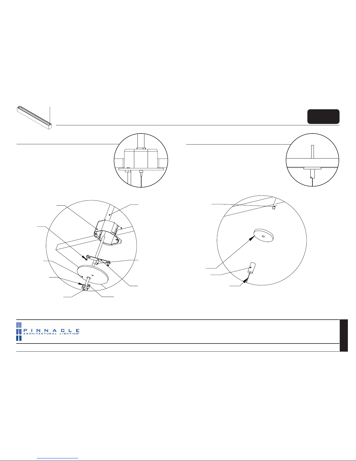
Step 2:
Non Power Mount
Step 1:
Power at Ceiling
1. Layout mounting/ junction box locations. Begin row
with fixture label at first mounting point.
2. Thread 1/4-20 stud to crossbar for power mounts.
3. Install crossbar to 4-octagonal junction box.
4. Run SJT cord through canopy and into junction box,
secure with strain relief.
5. Make all necessary wiring connections.
6. Feed aircraft cable through coupler, secure canopy to
crossbar bolt using coupler.
1. Install 1/4-20 stud for non-power mounts (1/2” below
ceiling plane).
2. Feed aircraft cable through coupler.
3. Secure canopy to bolt using coupler.
AC - to - JB Mount
EDGE
EX33
EX44
© 2017 Pinnacle Architectural Lighting
EdgeEX33_44_Booklet_January 2017
T5/T5HO/T8/LED
5 of 25
1. This product must be installed in accordance with applicable installation and electrical codes by a professional familiar with the
construction and operation of the product.
2. Minimum 90ºC supply conductors
3. All electrical connections must be performed by a certified electrician to applicable local and national electrical codes.
4. Fixtures must be mounted directly to structure.
5. The holding strength of AC cables cannot be guaranteed if the cables are damaged in any way.
Return to
Main Menu
AC cables with damage, bends, kinks, fraying, or knots must be discarded and replaced with new components. Never install a fixture where the AC cable is more than 5 degrees from perpendicular to the fixture. Fixtures are never to be raised by the cables (instead, lift the fixture up and adjust the cable position). Overtightening of hardware on grippers can damage AC cables. Never
exert force down onto the top of the fixture once it is hanging by safety cables. Never cut safety cables prior to installation. The first zip tie on the SJT and AC cables below the ceiling/canopy
must be no closer than 12” from the ceiling/canopy
Page 6

EDGE
EX33
EX44
T5/T5HO, T8 & LED
AC-TO-ST MOUNT INSTALLATION
Page 7
12655 E. 42nd Ave. #50 Denver, CO 80239 Phone: 303.322.5570 Fax: 303.322.5568 www.pinnacle-ltg.com
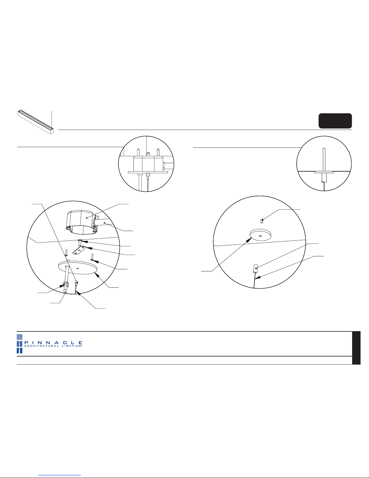
Step 2:
Non Power Mount
Step 1:
Power at Ceiling
1. Layout mounting/ junction box locations. Begin row
with fixture label at first mounting point.
2. Install 4-octagonal junction box to structure adjacent to
power feed mount locations.
3. Attach crossbar to junction box.
4. Run SJT power cord through canopy and into junction
box. Secure using provided strain relief.
5. Make necessary power connections.
6. Feed Aircraft cable through coupler and secure canopy
to junction using coupler (provided).
1. Install 1/4-20 studs to structure at all mounting points
(3/4” below ceiling plane.)
2. Feed aircraft cable through coupler (if applicable).
5. Secure coupler assembly to 1/4-20 bolt or stud.
AC - to - ST Mount
EDGE
EX33
EX44
© 2017 Pinnacle Architectural Lighting
EdgeEX33_44_Booklet_January 2017
T5/T5HO/T8/LED
7 of 25
1. This product must be installed in accordance with applicable installation and electrical codes by a professional familiar with the
construction and operation of the product.
2. Minimum 90ºC supply conductors
3. All electrical connections must be performed by a certified electrician to applicable local and national electrical codes.
4. Fixtures must be mounted directly to structure.
5. The holding strength of AC cables cannot be guaranteed if the cables are damaged in any way.
Return to
Main Menu
AC cables with damage, bends, kinks, fraying, or knots must be discarded and replaced with new components. Never install a fixture where the AC cable is more than 5 degrees from perpendicular to the fixture. Fixtures are never to be raised by the cables (instead, lift the fixture up and adjust the cable position). Overtightening of hardware on grippers can damage AC cables. Never
exert force down onto the top of the fixture once it is hanging by safety cables. Never cut safety cables prior to installation. The first zip tie on the SJT and AC cables below the ceiling/canopy
must be no closer than 12” from the ceiling/canopy
4 - Octagonal
Junction Box
(by others)
5” Power Canopy
Strain Relief
18ga. SJT Cord
Cross-Bar
Conduit and Fittings
(by others)
1/4-20 Stud
#8 Junction
Box Screws
Coupler
Aircraft Cable
*
Stud sits 1/2”
Below Ceiling Plane
1/4-20 Stud
(by others)
Aircraft Cable
Coupler
2” Non-Power
Canopy
Page 8
EDGE
EX33
EX44
T5/T5HO, T8 & LED
AC-TO-FIXTURE INSTALLATION
Page 9

12655 E. 42nd Ave. #50 Denver, CO 80239 Phone: 303.322.5570 Fax: 303.322.5568 www.pinnacle-ltg.com
1. Attach #8-32 screw to gripper through slot.
2. Slide aircraft cable through gripper.
3. Adjust gripper side to side to level fixture then tighten.
4. Repeat process for each subsequent fixture.
5. Re-level previous fixtures as necessary.
Step 3:
AC Mounting (Indirect)
T5/T5HO/T8/LED
AC - to - Fixture Mount
EDGE
EX33
EX44
© 2017 Pinnacle Architectural Lighting
9 of 25
EdgeEX33_44_Booklet_January 2017
1. This product must be installed in accordance with applicable installation and electrical codes by a professional familiar with the
construction and operation of the product.
2. Minimum 90ºC supply conductors
3. All electrical connections must be performed by a certified electrician to applicable local and national electrical codes.
4. Fixtures must be mounted directly to structure.
5. The holding strength of AC cables cannot be guaranteed if the cables are damaged in any way.
Return to
Main Menu
Slot
#8-32 Screw
Mount Spacing
Aircraft Cable - Example Rows
Mount Spacing
47-1/4”, 95-1/4”,
143-1/4”
Mount Spacing
47-1/4”, 95-1/4”,
143-1/4”
48, 96, 144”
Mount Spacing
Individual Fixture First Fixture Consecutive Fixtures
Gripper
Adjustable Cable
Page 10

End Trim
(2 per section)
Quick Connects
#8-32x1-1/8” Bolt
12655 E. 42nd Ave. #50 Denver, CO 80239 Phone: 303.322.5570 Fax: 303.322.5568 www.pinnacle-ltg.com
1. Install End Trim after louver installation.
Two (2) per 4’ section
Three (3) per 8’ section
Four (4) per 12’ section
1. Install first fixture with two (2) mounting points.
2. Subsequent fixtures use one (1) mount.
3. Install two (2) #8-32 bolt into each fixture as shown.
4. Raise adjoining fixture and slip bolt heads through key-hole slot.
5. Attach mounting to fixture as previously shown.
6. Make necessary wiring connections between fixtures ensuring all wires are
properly matched.
7. Tighten the previously installed #8-32x1-1/8” (1/2 turn past hand tight) to complete joining and create ground.
Step 5:
Joining Fixtures
1. Install end plates prior to lens/louver installation.
2. Place against end of fixture and secure using two (2) #6-32
nuts.
Step 6:
Finishing
EX33 Louver End Trim
EDGE
EX33
EX44
T5/T5HO/T8/LED
AC - to - Fixture Mount
© 2017 Pinnacle Architectural Lighting
10 of 25
EdgeEX33_44_Booklet_January 2017
1. This product must be installed in accordance with applicable installation and electrical codes by a professional familiar with the
construction and operation of the product.
2. Minimum 90ºC supply conductors
3. All electrical connections must be performed by a certified electrician to applicable local and national electrical codes.
4. Fixtures must be mounted directly to structure.
5. The holding strength of AC cables cannot be guaranteed if the cables are damaged in any way.
Return to
Main Menu
Page 11

EDGE
EX33
EX44
T5/T5HO, T8 & LED
PP-TO-JB MOUNT INSTALLATION
Page 12

4 - Octagonal
Junction Box
(by others)
5” Slip Canopy
Conduit and Fittings
(by others)
Pendant
Cross-Bar
(3/8 IP)
3/8 IP Pendant Pipe
#8 Junction Box
Screws (by others)
4 - Octagonal
Junction Box
(by others)
5” Slip Canopy
Pendant
Cross-Bar
(3/8 IP)
3/8 IP Pendant Pipe
#8 Junction Box
Screws (by others)
Set Screw
Set Screw
12655 E. 42nd Ave. #50 Denver, CO 80239 Phone: 303.322.5570 Fax: 303.322.5568 www.pinnacle-ltg.com
PP - to - JB Mount
Step 2:
Non Power Mount
Step 1:
Power at Ceiling
1. Install 4-Octagonal Junction boxes to structure at all
mounting locations (see spacing on page 2). Begin row
with fixture label at first mounting point.
2. Install conduit from building power to J-Box.
3. Install crossbar to J-Box
4. Feed slip canopy over pendant and secure pendant
to crossbar.
5. Feed power from J-Box through pendant and out
leaving 12” for fixture wiring.
6. Make all necessary wiring connections.
1. Attach 4-Octagonal Junction boxes to structure at all
mounting locations.
2. Install crossbar to J-Box.
3. Slide slip canopy over pendant.
4. Rotate pendant onto crossbar.
5. Slide canopy up to ceiling level and secure with set
screw.
EDGE
EX33
EX44
© 2017 Pinnacle Architectural Lighting
12 of 25
EdgeEX33_44_Booklet_January 2017
T5/T5HO/T8/LED
1. This product must be installed in accordance with applicable installation and electrical codes by a professional familiar with the
construction and operation of the product.
2. Minimum 90ºC supply conductors
3. All electrical connections must be performed by a certified electrician to applicable local and national electrical codes.
4. Fixtures must be mounted directly to structure.
5. The holding strength of AC cables cannot be guaranteed if the cables are damaged in any way.
Return to
Main Menu
Page 13

EDGE
EX33
EX44
T5/T5HO, T8 & LED
PP-TO-ST MOUNT INSTALLATION
Page 14

4 - Octagonal
Junction Box
(by others)
Conduit and Fittings
(by others)
Pendant Crossbar (3/8 IP)
#8 Junction Box Screws
(by others)
5” Slip Canopy
Set Screw
4 - Octagonal
Junction Box
(by others)
Pendant Crossbar (3/8 IP)
#8 Junction Box Screws
(by others)
5” Slip Canopy
Set Screw
12655 E. 42nd Ave. #50 Denver, CO 80239 Phone: 303.322.5570 Fax: 303.322.5568 www.pinnacle-ltg.com
PP - to - ST Mount
Step 2:
Non Power Mount
Step 1:
Power at Ceiling
1. Install 4-Octagonal Junction boxes to structure at all
mounting locations.(see spacing on page 2). Begin row with
fixture label at first mounting point.
2. Install conduit from building power to J-Box.
3. Install crossbar to J-Box
4. Feed slip canopy over pendant and secure pendant to
crossbar.
5. Feed power from J-Box through pendant and out leaving 12” for fixture wiring.
6. Make all necessary wiring connections.
1. Attach 4-Octagonal Junction boxes to structure at all
mounting locations.
2. Install crossbar to J-Box.
3. Slide slip canopy over pendant.
4. Rotate pendant onto crossbar.
5. Slide canopy up to ceiling level and secure with set
screw.
EDGE
EX33
EX44
© 2017 Pinnacle Architectural Lighting
14 of 25
EdgeEX33_44_Booklet_January 2017
T5/T5HO/T8/LED
1. This product must be installed in accordance with applicable installation and electrical codes by a professional familiar with the
construction and operation of the product.
2. Minimum 90ºC supply conductors
3. All electrical connections must be performed by a certified electrician to applicable local and national electrical codes.
4. Fixtures must be mounted directly to structure.
5. The holding strength of AC cables cannot be guaranteed if the cables are damaged in any way.
Return to
Main Menu
Page 15

EDGE
EX33
EX44
T5/T5HO, T8 & LED
PP-TO-FIXTURE INSTALLATION
Page 16

12655 E. 42nd Ave. #50 Denver, CO 80239 Phone: 303.322.5570 Fax: 303.322.5568 www.pinnacle-ltg.com
First Fixture
48”, 96”, 144”
Spacing
48”, 96”, 144”
Spacing
Consecutive Fixtures
Pendant - Example Rows
Mount Spacing
43-1/2”, 91-1/2”,
139-1/2”
Mount Spacing
43-1/2”, 91-1/2”,
139-1/2”
Individual Fixture
Cross bar
Nut
Pendant Pipe
Fixture Power
Wires
Building Power
Wires
Step 3:
PP Mounting
Step 4:
Making the connections
1. Pull wires through pendant pipe.
2. Make necessary wiring connections, ensuring all wires are
properly matched.
3. Recess wires back into housing.
(Note: UL label side has stripped wires and ground lead.)
1. Attach pendant pipe to fixture. Two (2) mounts for first fixture in
row/ individual, one (1) mount at opposite end for every fixture after.
2. Tighten down Nut to secure pendant pipe to fixture.
3. If power side mount run power wires into housing through pendant pipe.
(Note: Once run is mounted cover any unused knock outs)
PP - to - ST Mount
EDGE
EX33
EX44
© 2017 Pinnacle Architectural Lighting
16 of 25
EdgeEX33_44_Booklet_January 2017
T5/T5HO/T8/LED
1. This product must be installed in accordance with applicable installation and electrical codes by a professional familiar with the
construction and operation of the product.
2. Minimum 90ºC supply conductors
3. All electrical connections must be performed by a certified electrician to applicable local and national electrical codes.
4. Fixtures must be mounted directly to structure.
5. The holding strength of AC cables cannot be guaranteed if the cables are damaged in any way.
Return to
Main Menu
Page 17

End Trim
Joining Hardware
Quick Connects
12655 E. 42nd Ave. #50 Denver, CO 80239 Phone: 303.322.5570 Fax: 303.322.5568 www.pinnacle-ltg.com
1. Install first fixture with two (2) mounting points.
2. Subsequent fixtures use one (1) mount.
3. Install two (2) #8-32 joining hardware as shown below.
4. Raise adjoining fixture and slip bolt heads through key-hole slot.
5. Attach mounting to fixture as previously shown.
6. Make necessary wiring connections between fixtures ensuring all wires are
properly matched.
7. Tighten the previously installed #8-32x1-1/8” (1/2 turn past hand tight) to complete joining and create ground.
Step 5:
Joining Fixtures
1. Install end plates prior to lens/louver installation.
2. Place against end of fixture and secure using two (2) #6-32
nuts.
Step 6:
Finishing
1. Install End Trim after louver installation.
Two (2) per 4’ section.
Three (3) per 8’ section
Four (4) per 12’ section
EX33 Louver End Trim
PP - to - ST Mount
EDGE
EX33
EX44
© 2017 Pinnacle Architectural Lighting
17 of 25
EdgeEX33_44_Booklet_January 2017
T5/T5HO/T8/LED
1. This product must be installed in accordance with applicable installation and electrical codes by a professional familiar with the
construction and operation of the product.
2. Minimum 90ºC supply conductors
3. All electrical connections must be performed by a certified electrician to applicable local and national electrical codes.
4. Fixtures must be mounted directly to structure.
5. The holding strength of AC cables cannot be guaranteed if the cables are damaged in any way.
Return to
Main Menu
Page 18

EDGE
EX33
EX44
T5/T5HO, T8 & LED
SURFACE MOUNT INSTALLATION
Page 19

12655 E. 42nd Ave. #50 Denver, CO 80239 Phone: 303.322.5570 Fax: 303.322.5568 www.pinnacle-ltg.com
1. Remove top plug from both ends of beginning of run fixture(s) and
on end of continuous fixture(s)
2. Remove lens/ louver options from fixture(s).
3. Remove reflector from housing by removing reflector screws.
4. Feed necessary through wires out of top access hole.
1. Install junction box (by others) with crossbar (by others) into ceiling.
2. Mount fixture to crossbar using a nipple (by others).
3. Feed wires through nipple and connect to building power ensuring all
wires are properly matched.
4. Subsequent non power locations mount to structure.
Surface Mount Instructions
Step 1:
Fixture Prep
Step 2:
Mounting and Power
Crossbar
(by others)
Junction Box
(by others - size according
to fixture width)
Nipple 1/4” x 1”
(by others)
1/4” Nut
(byu others)
EX33 width = 2-7/8”
EX44 width = 4-7/16”
Plug
Hole Size = 7/8”
3/8” IP
Reflector
Lens
Reflector
Screws
Through wire
If MR16 Unit
2-1/4”
91-1/2”
2-1/4”
2-1/4” 2-1/4”
43-1/2”
48”
Individual Spacing
96”
8’ 8’ 8’
First Fixture
91-1/2”
96” Spacing 96” Spacing
Mount Spacing Example Rows
End Plates Not Included
Fixture Lenghts: 48”, 96”, 144” (add 6” per MR16)
First/ Individual Fixture
Mount Spacing (C-to-C)
4’ = 43-1/2”
8’ = 91-1/2”
12’ = 139-1/2”
EDGE
EX33
EX44
© 2017 Pinnacle Architectural Lighting
19 of 25
EdgeEX33_44_Booklet_January 2017
T5/T5HO/T8/LED
1. This product must be installed in accordance with applicable installation and electrical codes by a professional familiar with the
construction and operation of the product.
2. Minimum 90ºC supply conductors
3. All electrical connections must be performed by a certified electrician to applicable local and national electrical codes.
4. Fixtures must be mounted directly to structure.
5. The holding strength of AC cables cannot be guaranteed if the cables are damaged in any way.
Return to
Main Menu
Page 20

End Trim
(2 per section)
Quick Connects
#8-32x1-1/8” Bolt
12655 E. 42nd Ave. #50 Denver, CO 80239 Phone: 303.322.5570 Fax: 303.322.5568 www.pinnacle-ltg.com
1. Install End Trim after louver installation.
Two (2) per 4’ section
Three (3) per 8’ section
Four (4) per 12’ section
1. Install first fixture with two (2) mounting points.
2. Subsequent fixtures use one (1) mount.
3. Install two (2) #8-32 bolt into each fixture as shown.
4. Raise adjoining fixture and slip bolt heads through key-hole slot.
5. Attach mounting to fixture as previously shown.
6. Make necessary wiring connections between fixtures ensuring all wires are
properly matched.
7. Tighten the previously installed #8-32x1-1/8” (1/2 turn past hand tight) to complete joining and create ground.
Step 3:
Joining Fixtures
1. Install end plates prior to lens/louver installation.
2. Place against end of fixture and secure using two (2) #6-32
nuts.
Step 4:
Finishing
EX33 Louver End Trim
Surface Mount Instructions
EDGE
EX33
EX44
© 2017 Pinnacle Architectural Lighting
20 of 25
EdgeEX33_44_Booklet_January 2017
T5/T5HO/T8/LED
1. This product must be installed in accordance with applicable installation and electrical codes by a professional familiar with the
construction and operation of the product.
2. Minimum 90ºC supply conductors
3. All electrical connections must be performed by a certified electrician to applicable local and national electrical codes.
4. Fixtures must be mounted directly to structure.
5. The holding strength of AC cables cannot be guaranteed if the cables are damaged in any way.
Return to
Main Menu
Page 21

EDGE
EX33
EX44
T5/T5HO, T8 & LED
WALL MOUNT INSTALLATION
Page 22

Wall Mount
Screw/ Washer
Fixture Side
Mounting Bracket
6-7/16”
5-1/4”
1-5/16”
3-1/4”
2-7/16”
Step 2:
Power Mount
12655 E. 42nd Ave. #50 Denver, CO 80239 Phone: 303.322.5570 Fax: 303.322.5568 www.pinnacle-ltg.com
Step 1:
Wall Bracket
1. Attach wall side bracket to structure via mounting
hardware (by others).
2. If power side, mount bracket in line with 2x4 junction
box (by others).
3. Bring power in through junction box.
4. Follow mount spacing on page 2 for additional
mounting points.
(Note: See page 2 for additional mount dimensions)
1. To power fixture attach building power to fixture power
wires using push nuts.
2. Recess connections into junction box.
3. Attach fixture to wall bracket as shown.
4. Make necessary adjustments laterally prior to tightening
wall mount screw.
(Note: See page 2 for additional mount dimensions)
Step 3:
Joining Fixtures
Step 4:
Finishing
1. Install joining kit hardware.
2. Slip adjacent fixture’s mounting hardware through the
keyhole slots on the end plates.
3. Make wiring connections between fixtures, and recess
wires into one of the fixtures.
4. Tighten joining hardware.
1. Install end caps.
2. Place against end of fixture and secure using two (2)
#8-32 screws.
Wall Mount Instructions
1. Install End Trim after louver installation.
Two (2) per 4’ section.
Three (3) per 8’ section
Four (4) per 12’ section
EX33 Louver End Trim
EDGE
EX33
EX44
© 2017 Pinnacle Architectural Lighting
22 of 25
EdgeEX33_44_Booklet_January 2017
T5/T5HO/T8/LED
1. This product must be installed in accordance with applicable installation and electrical codes by a professional familiar with the
construction and operation of the product.
2. Minimum 90ºC supply conductors
3. All electrical connections must be performed by a certified electrician to applicable local and national electrical codes.
4. Fixtures must be mounted directly to structure.
5. The holding strength of AC cables cannot be guaranteed if the cables are damaged in any way.
Return to
Main Menu
Page 23

88”
96”
Wall
Fixture
7’-4” Center to Center of Bracket (first fixture)
2 Mounting Brackets
8’ Center to Center of Bracket (continuous fixture)
1 Mounting Bracket
1/2”
7/8”
1-1/16”
7/8”
2-1/8”
(Mounted in Center)
3/8”
(Mounted in Center)
D
C
A
B
A
B
C
D
12655 E. 42nd Ave. #50 Denver, CO 80239 Phone: 303.322.5570 Fax: 303.322.5568 www.pinnacle-ltg.com
First/ Independent Fixture Mounting Example
Intermediate/ End Fixture Mounting Example
2’-0” Center to center of bracket
3’-0” Center to center of bracket
4’-0” Center to center of bracket
8’-0” Center to center of bracket
12’-0” Center to center of bracket
1’-4” Center to center of bracket
2’-4” Center to center of bracket
3’-4” Center to center of bracket
7’-4” Center to center of bracket
11’-4” Center to center of bracket
24”
36”
48”
96”
144”
16”
28”
40”
88”
136”
Note: Power typically
on left side of fixture.
* *
Wall Mount Instructions
EDGE
EX33
EX44
© 2017 Pinnacle Architectural Lighting
23 of 25
EdgeEX33_44_Booklet_January 2017
T5/T5HO/T8/LED
1. This product must be installed in accordance with applicable installation and electrical codes by a professional familiar with the
construction and operation of the product.
2. Minimum 90ºC supply conductors
3. All electrical connections must be performed by a certified electrician to applicable local and national electrical codes.
4. Fixtures must be mounted directly to structure.
5. The holding strength of AC cables cannot be guaranteed if the cables are damaged in any way.
Return to
Main Menu
Page 24

EDGE
EX33
EX44
LENS
DETAIL
Page 25

© 2017 Pinnacle Architectural Lighting
12655 E. 42nd Ave. #50 Denver, CO 80239 Phone: 303.322.5570 Fax: 303.322.5568
25 of 25
www.pinnacle-ltg.com
Snap In Lens
Lensing detail sheet
Lens Installation Lens Removal
1. Begin at one end of the fixture and insert lens into appropriate position
where it will snap into place.
2. Gradually insert the lens along the length of the fixture, snapping it into
place as you go.
3. If at any point the lens becomes difficult to insert press slightly into the
center of the lens in order to allow for it to flex, temporarily decreasing the
width of the lens.
1. Insert a rigid object approx. 1/16” thick, such as a quarter, into the edge
between the lens and the fixture, approx. 1-2” from the end of the lens.
(6” for regress lens)
2. Using said object, gently pry lens away from fixture until it is released
from the mounting edge.
3. Once the section is released, start at one end of the fixture and pull the
lens out of the fixture.
EdgeEX33_44_Booklet_January 2017
Fixture End
Snap-In Lens
Note: Low temperatures can effect the lens material,
making it brittle. Please allow the lenses to warm
to room temperature before installation.
Approx. 1-2” Away
From Fixture End
Snap-In Lens
Flexed for Installation
Approx. location
to allow for flex
EDGE
Return to
Main Menu
 Loading...