

Page 1

Pinnacle Systems DV500
U
SER'S GUIDE
Page 2

Pinnacle Systems DV500
User’s Guide
Version 1.2 / GB September 2000
41000052
© Pinnacle Systems 2000
All rights reserved.
No part of this manual may be reproduced or transferred to other media without explicit written
permission from Pinnacle Systems, Braunschweig, Germany.
All brand or product names are trademarks or registered trademarks of their respective holders.
This manual is printed on chlorine-free paper using environmentally safe ink.
Pinnacle Systems. has written this manual to the best of its knowledge, but does not guarantee that the
programs/systems will fulfill the desires of the user.
No warranty is made as to the specifications of features.
Pinnacle Systems. retains the right to make alterations to the content of the manual without the obligation
to inform third parties.
All tenders, sales, supply and manufacturing contracts from Pinnacle Systems., including consultancy,
installation and other contractual performance are subject exclusively to the General Sales and Delivery
Terms of Pinnacle Systems.
Page 3

Contents
CHAPTER 1: WELCOME 1
G
ENERAL
DV500 P
A
DDITIONAL INFORMATION
S
OLUTIONS FOR VIDEO APPLICATIONS EVERYWHERE
A
DOBE PREMIERE SUPPORT
H
OW THIS GUIDE IS ORGANIZED
RODUCT FEATURES
CHAPTER 2: BEFORE YOU BEGIN 7
S
YSTEM REQUIREMENTS
P
ACKAGE CONTENTS
CHAPTER 3: INSTALLING ADOBE PREMIERE 10
CHAPTER 4: INSTALLING THE HARDWARE 11
D
EFRAGMENTING THE HARD DISK
I
NSTALLING THE
DV500 11
11
CHAPTER 5: CONNECTING THE BLUEBOX AND THE VIDEO
DEVICES 14
C
ONNECTING THE VIDEO DEVICES
P
LAYER AND RECORDER IN ONE DEVICE
C
ONNECTING THE VIDEO MONITOR AND LOUDSPEAKERS
15
21
22
1
2
3
4
4
5
7
8
CHAPTER 6: INSTALLING THE DV500 SOFTWARE 23
I
NSTALLING THE SOFTWARE FOR WINDOWS
I
NSTALLING THE SOFTWARE FOR WINDOWS
A
DDITIONAL INFORMATION (INSTALLATION PROGRAM
NT 4.0 24
2000/98 25
)27
CHAPTER 7: CAPTURE, EDITING AND PLAYBACK 30
Q
UICK CAPTURE CHECKLIST
C
APTURING VIDEO IN DETAIL
E
DITING THE CLIPS
P
LAYBACK
O
UTPUTTING THE PROJECT
D
EVICE CONTROL
30
31
35
36
37
38
CHAPTER 8: DV500 CONTROL 43
S
ETTINGS—VIDEO INPUT
S
ETTINGS—VIDEO FORMAT
S
ETTINGS—AUDIO INPUT
S
ETTINGS—OUTPUT
S
ETTINGS—GENERAL
44
45
46
47
49
CHAPTER 9: WORKING WITH DV MATERIAL 51
M
AKING MOVIES
C
APTURING SINGLE FRAMES (SNAPSHOTS
)61
51
User's Guide
i
Page 4

CHAPTER 10: DVTOOLS 64
C
APTURE GALLERY
T
APE GALLERY
DV D
EVICE CONTROLLER
64
69
70
CHAPTER 11: TRANSITIONS, FILTERS, AND
SUPERIMPOSITIONS 76
T
RANSITIONS
F
ILTERS
S
UPERIMPOSITIONS
76
82
85
CHAPTER 12: PINNACLE FREEFX 86
CHAPTER 13: INSTANT VIDEO 93
W
I
NSTANT VIDEO WINDOW
M
R
ENDERING PREVIEWS
L
IMITATIONS
Instant Video? 93
HAT IS
ODES OF OPERATION
94
99
100
100
CHAPTER 14: TITLEDEKO 101
W
ELCOME TO TITLEDEKO
L
AUNCHING TITLEDEKO
T
HE TITLEDEKO USER INTERFACE
S
ELECTING TEXT AND OBJECTS
F
ORMATTING TEXT AND OBJECTS
T
OOLS AND SELECTION HANDLES
T
RANSFORMING TEXT AND OBJECTS
U
SING AND MODIFYING LOOKS AND STYLES
T
HE BACKGROUND
L
ET’S MAKE A TITLE
101
102
103
107
109
111
113
114
117
119
CHAPTER 15: VIDEO SPICERACK 127
K
EY CONCEPTS OF VIDEO SPICERACK
H
OW DOES A GRADIENT IMAGE MAKE A TRANSITION
V
IDEO SPICERACK CATEGORIES
H
OW TO USE SPICERACK
? 127
127
128
129
CHAPTER 16: HOLLYWOOD FX 130
W
HAT IS HOLLYWOOD
I
NSTALLATION OF HOLLYWOOD
FX? 130
FX 131
CHAPTER 17: EXPORT TO AVI, DV- OR MPEG2 133
S
ETTING
E
XPORT TO
E
XPORT TO
A
DVANCED EXPORT SETTINGS
–MPEG
FORMAT
MPEG2 133
DV AVI 134
133
135
CHAPTER 18: TECHNICAL DATA 140
Pinnacle Systems DV500
ii
Page 5

APPENDIX A: MPEG COMPRESSION I
T
HE COMPRESSION PROCEDURE
MPEG I
APPENDIX B TROUBLESHOOTING IV
G
ENERAL
P
ROBLEMS AND SOLUTIONS
P
ROBLEMS WITH THE VIDEO DISPLAY ON THE
P
ROBLMS WITH INTERUPT SHARING
P
ROBLEMS WITH CAPTURE
P
ROBLEMS WITH EDITING AND RENDERING
P
ROBLEMS WITH PLAYBACK AND OUTPUT
P
ROBLEMS AND SOLUTIONS—PINNACLE FREE
P
ROBLEMS AND SOLUTIONS
O
THER PROBLEMS AND LIMITATIONS
P
ROBLEMS WITH THE COMPATIBILITY OF VIDEO DEVICES
- G
ENERAL
- A
FTER EFFECTS
PC S
CREEN
FX XV
IV
IV
VI
VII
IX
XII
XVI
XVI
XVII
APPENDIX C: ERROR MESSAGES XVIII
APPENDIX D: MULTIMEDIA TERMINOLOGY XIX
APPENDIX F: LICENSE AGREEMENT XXVIII
INDEX
X
User's Guide
iii
Page 6

F
y
OR YOUR OWN SAFETY
NOTE: Shielded cables should be used for a composite interface. This is to ensure
continued protection against radio frequency interference.
FCC Compliance Statement
FCC W
C
AUTION
ARNING STATEMENT
NOTE: This equipment has been tested and found to comply with the limits for a
Class B digital device, pursuant to Part 15 of the FCC Rules. These limits are
designed to provide reasonable protection against harmful interference in a
residential installation. This equipment generates, uses and can radiate radio
frequency energy and, if not installed and used in accordance with the instructions,
may cause harmful interference to radio communications. However, there is no
guarantee that interference will not occur in a particular installation. If this
equipment does cause harmful interference to radio or television reception, which
can be determined by turning the equipment off and on, the user is encouraged to
try to correct the interference by one or more of the following measures:
•
Reorient or relocate the receiving antenna.
•
Increase the separation between the equipment and receiver.
•
Connect the equipment into an outlet on a circuit different from that to which
the receiver is connected.
•
Consult the dealer or an experienced radio/TV technician for help.
Changes or modifications not expressly approved by the party responsible for
compliance could void the user's authority to operate the equipment.
L
ABEL WARNING
Pinnacle Systems DV500
iv
Shielded interface cable must be used in order to comply with the emission limits.
This device complies with Part 15 of the FCC Rules. Operation is subject to the
following two conditions: (1) this device may not cause harmful interference, and
(2) this device must accept any interference received, including interference that
may cause undesired operation.
Pinnacle Systems DV500
Tested To Comp l
With FCC Standards
FOR HOME OR OFFICE USE
Page 7

About the User’s Guide
This User’s Guide explains how to install and use the Pinnacle Systems
DV500 hardware and software. Instead of using the complete product name,
the abbreviation DV500 is used for a better readability.
Subheadings
In the margins are subheadings to help you quickly find your way through
this manual.
Important text passages are marked with the “notepad” and this format.
Numbers mark step by step instructions:
1. Start TitleDeko.
Bullets mark instructions for optional steps the order of which is not
important.
Connect the board to the camcorder.
•
All keyboard commands appear in this font:
install
Menus, commands, options or buttons which the user can select are written
in
italics.
User's Guide
v
Page 8

For your own safety
In the interest of your own safety and the flawless functioning of your new
product and computer system please note the following:
Computer components are sensitive to static charge. Divert any
electrostatic charge from your person before touching the components
with your hands or any tools.
Before opening the computer make sure that the power plug is
disconnected from the wall outlet.
For changes or supplements that could not be included in the printed
documentation, please, refer to the ReadMe file on the CD-ROM supplied
with your system!.
Pinnacle Systems DV500
vi
Page 9

G
ENERAL
Chapter 1: Welcome
The next generation of video is digital and DV is the world-wide digital
standard. With the DV500, Pinnacle Systems offers a non-linear video
editing system that meets the highest quality standard for DV productions.
What makes this product special, however, is its incorporation of classic
post-production in
software rendering. A real-time effects mixer outputs entire productions or
creative ideas to the video monitor in full quality as soon as they have been
arranged.
The DV500 comes with more than
instantly in real-time. Furthermore, the card's effects mixer is also suitable
for titles and filters.
The combination of DV hardware codec and real-time effects mixer marks
the advent of dual-stream technology on standard desktop computers. No
comparable video editing system offers more
are visible instantly in full-quality video. In addition, videos can be
processed for digital data media such as DVD and CD.
real-time
—in other words, without time-consuming
200 wipes and dissolves
productivity
that run
, since the effects
The DV500 is able to save projects as MPEG export data directly from the
timeline so that DVD productions can be built.
The DV500 processes analog (S-Video, Composite video) and
IEEE 1394) signals via corresponding inputs and outputs.
With its outstanding features, the DV500 sets new standards for quality,
compatibility, and productivity.
digital
(DV,
Chapter 1: Welcome
1
Page 10

DV500 P
RODUCT FEATURES
Video resolution
720 x 576 (PAL) or 720 x 480 (NTSC) according to ITU.R 601, studio
quality, compatible with Betacam and DV; cropped size 704 x 576
(PAL), 704 x 480 (NTSC).
Bit rate
50 Mbit/sec in dual-stream mode.
25 Mbit/sec in single-stream mode
Encoding method
DV 25.
Bit rate control (for MP2 export only)
Constant (CBR) or variable bit-rate (VBR).
Audio
Support for
- 32 kHz 12 bit and 16 bit stereo
- 44 kHz 16 bit stereo
- 48 kHz 16 bit stereo
Playback mode
Dual stream – 2 video files via one mixer for real-time effects.
Titles, filters, and 200 wipes and dissolves without time-consuming
software rendering.
Production length
Up to 3 hours video productions larger than 2 GB.
Capture of files up to 12 TBytes in length.
Instant Video™
Intelligent, hardware-accelerated rendering, multi-file playback for
Audio processor, perfect, lip-synch audio processing in CD or DV
quality.
DVD and MPEG2-CD Production
Export MPEG2 ML@MP (4:2:0) using IBP format suitable for DVD
and MPEG2-CD authoring.
Direct interface to Minerva Impression.
Video overlay
Real-time monitoring on computer screen.
Video Standards
PAL, NTSC (US version NTSC only), audio input (stereo), audio output
(stereo).
Pinnacle Systems DV500
2
Standard ports
S-Video (Y/C) and Composite (CVBS).
DV (IEEE1394).
Page 11

A
DDITIONAL INFORMATION
Production Process
Productions created with DV500 can be output to analog (S-VHS, Hi8,
Betacam) or digital tape systems (DV) or stored as a file.
Files are saved in AVI format. Optionally, the MPEG II IBP compression
method can also be used. This material is suitable for subsequent processing
with DVD authoring software.
Real-time Processing
The DV500 is equipped with a real-time mixer, making it possible to mix
and output, according to the specifications of an effect, two videos that are
simultaneously being played back from the hard disk. This method is
especially useful for wipes and dissolves, since these consist of two
chronologically overlapping videos. Real-time playback occurs via the
analog ports of the card. For digital playback, the effects have to be
rendered.
DV500 offers more than 200 effects in real-time. DV500 can even
superimpose color titles and other graphics over a video without prior
rendering.
Instant Video
Instant Video coordinates playback of all videos within a production. In
particular, it provides for so-called “cutlist playback”, so that multiple video
files can be played back one after the other without interruption. The
intelligent software detects all postproduction steps that do not take place in
real-time, renders these quickly, and automatically integrates the result in
the production. Every production consisting of different materials can be
called up and played back again and again in context.
blueBOX
The blueBOX makes it easy to connect a video editing system to other video
equipment. Of course it is possible to use both analog signal sources (for
instance, camcorders) and recording devices (for instance, recorders) on the
same box at the same time. The video inputs and outputs are designed for SVideo (Y/C) and Composite (FBAS) signals. The stereo audio signals are
connected via line-out and line-in connections with cinch jacks.
The blueBOX can be positioned at your desktop so that it is always easily
accessible, making it easy to plug in and unplug cables. This enables you to
adapt the cabling between the blueBOX and other video devices to
individual conditions quickly and flexibly. All jacks are marked with easyto-understand symbols, thus ensuring fast, secure connections.
Chapter 1: Welcome
3
Page 12

S
OLUTIONS FOR VIDEO APPLICATIONS EVERYWHERE
No matter what kind of project you’re working on, DV500 gives you
everything you need for professional quality results.
With the DV500, your video production can be a function of your creativity,
not your budget. Just as it should be.
A
DOBE PREMIERE SUPPORT
Adobe Premiere provides:
Direct integration of the DV500 capture, playback and effects engine
within Adobe Premiere.
Intelligent Rendering, which automatically renders non-real-time
playable segments.
Source/program monitor consolidates clip, preview, trim and controller
windows.
Three-point editing.
Collapsible AfterEffects-like timeline.
Navigator palette speeds timeline access.
New, key-frameable video and audio filters.
DV device control.
Add Character to Your Productions with our TitleDeko Character Generator
Want to add easy-to-use, cutting-edge titling to your finishing station? Our
powerful TitleDeko character generator package comes standard with
DV500. This plug-in version of our industry-leading Deko CG product lets
you create your own title style, with customizable faces, edges, shadows and
underlines. TitleDeko’s library of text effects includes rotate, skew, glow,
emboss, texture, neon, metallic and extrude. With DV500, use TitleDeko to
easily add rolls and crawls, or other movements to your titles.
Integrate into any Digital Production Environment
With the onboard DV/1394 ports you can capture digital videos and output
them to a connected DV device.
Pinnacle Systems DV500
4
Page 13

H
OW THIS GUIDE IS ORGANIZED
This User Guide is not intended to be a supplement to the Adobe Premiere
User's Guide. For detailed information on Adobe Premiere, please refer to
the Adobe Premiere User's guide.
This manual consists of the following chapters:
Overview
The chapter “Welcome” introduces the DV500, provides an overview of its
capabilities and explains the organization of, and conventions used in, this
User’s Guide.
System requirements
The chapter “Before You Begin” gives you all necessary information about
the system requirements needed to work efficiently with DV500. In addition
the package contents are introduced in detail.
Installing Adobe Premiere
The chapter “Installing Adobe Premiere” tells you how to install Adobe
Premiere.
Hardware installation
The chapter “Installing the Hardware” explains the hardware installation.
Connecting the blueBOX
The chapter “Connecting the blueBOX” shows how to connect DV500, the
blueBOX and the video devices.
Software installation
The chapter “Installing the Software” describes the installation of the
software under Windows 98, Windows 2000, and Windows NT.
Capture
The chapter “Capture, Editing and Playback” gives you detailed information
on how to capture, edit and playback video clips to tape.
In addition, the Device control functions are described in detail.
DV500 Control
The chapter “DV500 Control ” describes all features of the Control, which
allows you to specify individual settings.
DV Material
The chapter “Working with DV Material” introduces step by step how to
capture video clips using the DVTools.
DVTools
The chapter “DVTools” describes in detail the functions of the three main
components of the DVTools: The Capture Gallery, the Tape Gallery, and the
DV Device Control.
Chapter 1: Welcome
5
Page 14

Effects
The chapter “Transitions, Filters and Supersition” introduces the Pinnacle
Systems’ real-time transitions and filters which allow you to check the
effects without having to render the clip.
3D Effects
The chapter “Pinnacle FreeFX” shows how to work with the Pinnacle
accelerated 3D effects.
Instant Video
The chapter “Instant Video” gives you information about how to minimizes
the rendering time under Adobe Premiere considerably.
TitleDeko
The chapter “TitleDeko” explains how to use the TitleDeko character
generator to add titles, rolls and crawls, with a variety of text effects.
Video SpiceRack
The chapter “Video SpiceRack” introduces Video SpiceRack, a collection of
300 top-quality transitions and dynamic effects.
Hollywood FX
The chapter “Hollywood FX” decribes how to generate 3D transitions and
near realtime effects for your videos.
Export
The chapter “Export to AVI, DVD- or MPEG2-CD” explains the settings
for an export of your project.
Technical data
The chapter “Technical Data” informs you about the most important data of
DV500.
Appendix
The “Appendix” contains a troubleshooting guide, a detailed multimedia
glossary and the declaration of conformity.
Index
An index concludes this User’s Guide.
Pinnacle Systems DV500
6
Page 15
This chapter tells you which computer system components are required for
the operation of the DV500 and what is included in the DV500 package
contents.
S
YSTEM REQUIREMENTS
Please make sure your system meets the following requirements before
installing the DV500:
PC System
Chapter 2:
Before You Begin
At least Pentium II
1 x 32-bit PCI 2.1 slot
Windows 98 / Windows 98 SE / Windows ME
128 MByte RAM
Windows 2000
196 MByte RAM
Windows NT
128 MByte RAM
500 MByte hard disk capacity for system files and programs, e.g. Adobe
Premiere 5.1a or higher
20 GByte hard disk capacity for capture / playback of video, able to
sustain at least 8 MBytes/sec transfer rate.
If you plan to use a DMA capable IDE hard disk (e.g. IDE-UDMA 100 or
IDE-UDMA 66) for your video, you should absolutely install a DMA
busmaster driver to ensure the smooth function of your DV500 board. You
will find this driver on the CD-ROM supplied with your motherboard, in the
internet, or contact your dealer.
400 or faster compatible processor
16-bit display adapter with DirectDraw drivers, OpenGL compatible
DirectX 7.0 or higher (for FreeFX)
CD-ROM drive
48 kHz compatible sound board.
Software
Windows 98, Windows 98SE, Windows ME, Windows 2000, or
Windows NT 4.0 SP4 or higher.
Chapter 2: Before you begin
7
Page 16
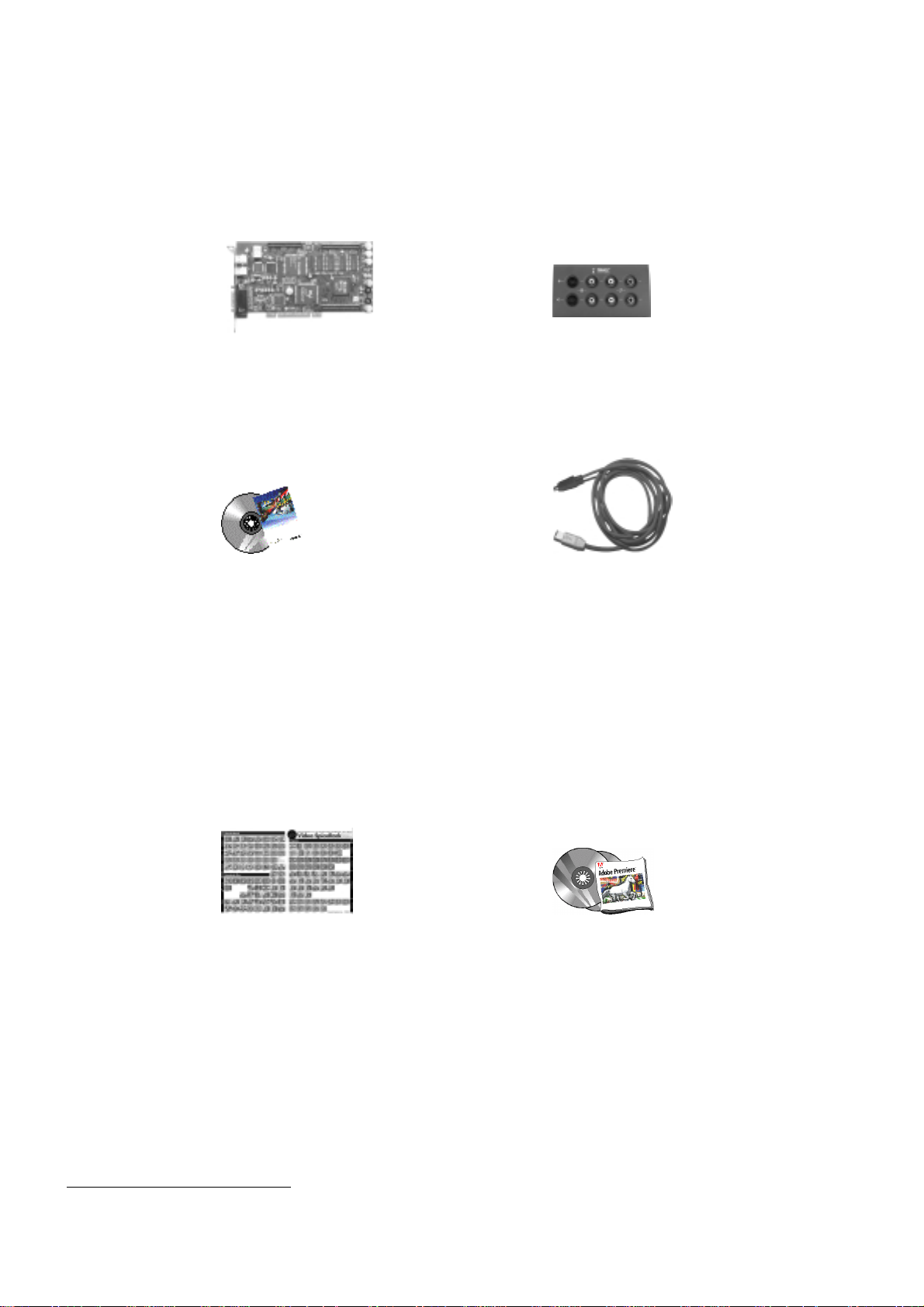
P
ACKAGE CONTENTS
Please make sure your DV500 system is complete before you begin the
*
installation. The system includes
:
DV500 board** blueBOX
CD-ROM with: IEEE-1394 cable
- drivers
- extended Adobe Premiere presets
- Instant Video
- Pinnacle TitleDeko
- online documentation
- FreeFX effects (not for Windows NT)
- Adobe Premiere Update
Pixèlan Video SpiceRack Adobe Premiere
Overview
*
Depending on the delivery scope, the package contents may vary from the contents listed in this manual.
**
For model and serial number of your board, refer to the label on the board.
Pinnacle Systems DV500
8
Page 17

Minerva Impression CD Documentation
Hollywood FX Copper
If any parts are missing, please contact your retailer.
Computer components are sensitive to electrostatic charge. Do not take the
DV500 board out of its antistatic package until you install it.
Related Information
Refer to Pinnacle at
information on configurations and software updates.
Refer to Microsoft Windows documentation, online help and Microsoft
Website for information on the Windows operating system.
http://www.pinnaclesys.com
for the latest
Chapter 2: Before you begin
9
Page 18

Chapter 3:
Installing Adobe Premiere
The following chapter describes the procedure to install Adobe
Premiere.
You must install Adobe Premiere
computer, because the DV500 presets must be copied to the appropriate
Adobe Premiere folder during the installation of the DV500 software.
Proceed as follows to install Adobe Premiere:
1. Place the Adobe Premiere CD-ROM in your CD-ROM drive.
2. If the installation program does not start automatically, select
the
3. Depending on your drive, enter, for example:
If your CD-ROM drive has a different drive designation, change the path
accordingly.
—or—
Click on
mentioned above and double-click the
4. Click OK.
5. Follow the program installation instructions on the screen.
menu.
Start
e:\premiere\setup.
Browse
..., switch to your CD-ROM drive and to the directory
before
installing the DV500 board in your
Run…
setup.exe
file.
from
6. Install the Adobe Premiere Update.
After
you have installed Adobe Premiere on your computer, you can install
the DV500 board and software.
If you ever need to reinstall Adobe Premiere, please remember to run the
DV500 installation again, selecting at a minimum the Presets and PlugIns.
DV500 will not work correctly with Adobe Premiere if these components
are missing.
Pinnacle Systems DV500
10
Page 19
Installing the Hardware
D
EFRAGMENTING THE HARD DISK
Before installing and configuring the DV500 you should defragment your
hard disk/s. Under Windows 98/98SE/ME you find the defragmenter tool
via
Programs, Accessories, System Tools, Disk Defragmenter
Chapter 4:
.
If you use Windows 2000, please proceed as follows: Click on
Computer
Properties
Defragment Now...
If you use DV500 under Windows NT, use a tool you can obtain from your
computer store to defragment your hard disk.
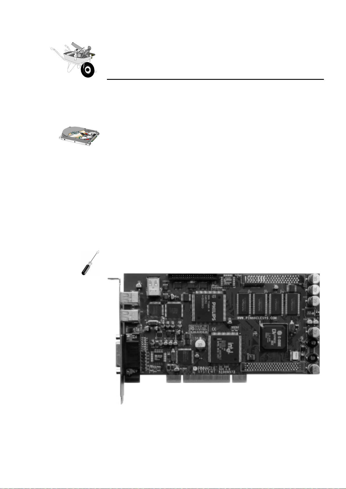
I
NSTALLING THE
The following chapter explains how to install the DV500 into your
computer.
, then click right on the disk to be defragmented, then choose
,
Tools
, and under
.
Defragmentation
click on the button
DV500
My
Chapter 4: Installing the Hardware
11
Page 20
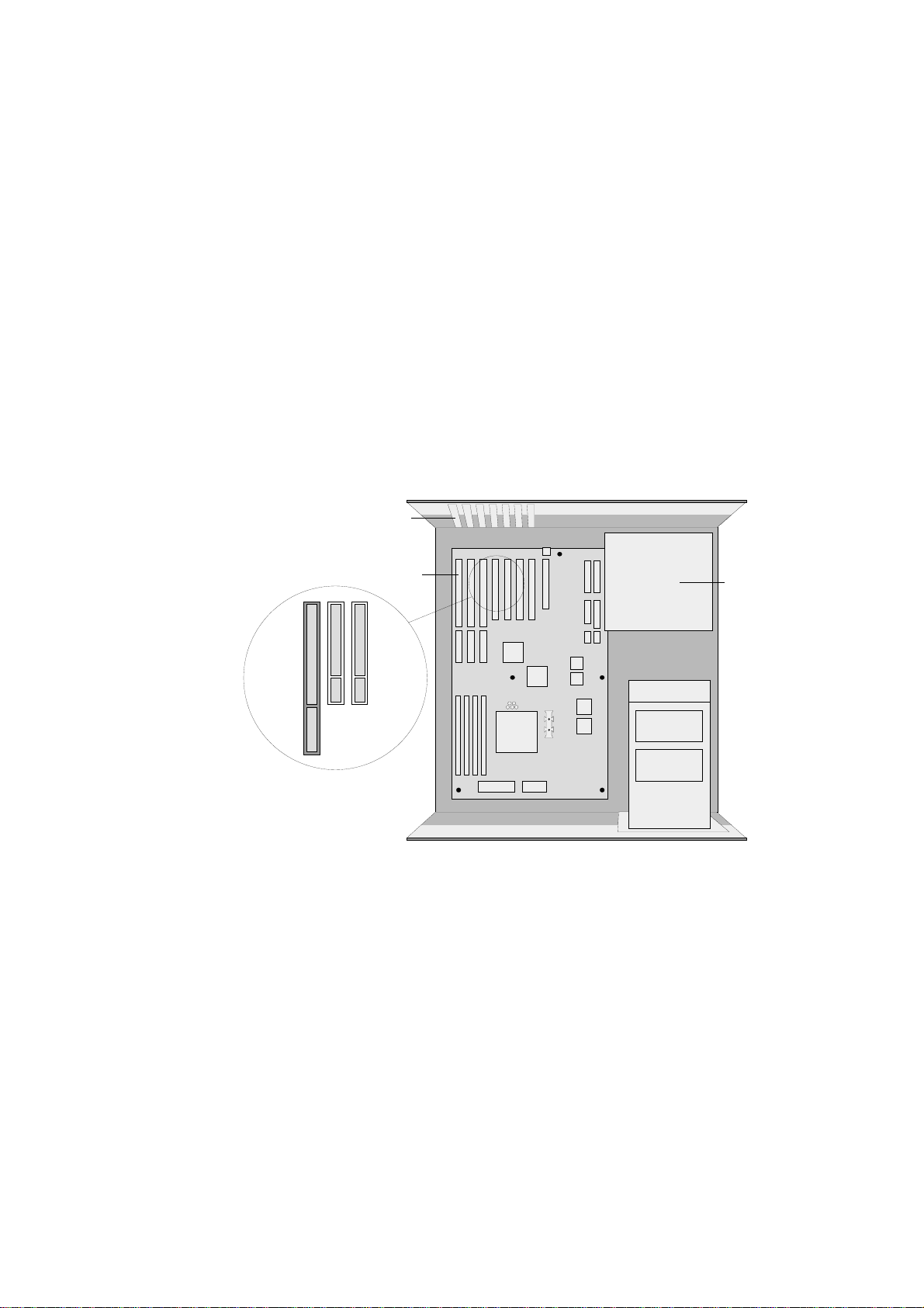
Inserting DV500
To insert the DV500 into your computer, proceed as follows:
1. Discharge yourself.
Discharge yourself by touching the metal case of your computer.
2. Switch off the computer, disconnect the cables.
Switch off the computer and all peripheral devices. Pull out the power
cord and disconnect all necessary cables.
3. Remove the cover.
Loosen the screws of the computer's cover and remove the cover.
4. Select a PCI slot.
Select a free (busmaster) PCI slot for the DV500 board.
Slot shields
Slots
PCI slots
5. Remove the slot bracket.
Remove the slot bracket at the back of the computer. If necessary,
remove the screw at the cover.
6. Insert the board.
Power
supply
unit
Pinnacle Systems DV500
12
Insert the board carefully in the selected slot. Hold the board at the top
edge and push both ends simultaneously into the slot. Press the board's
top edge to make sure that the board is firmly seated in the slot.
Page 21
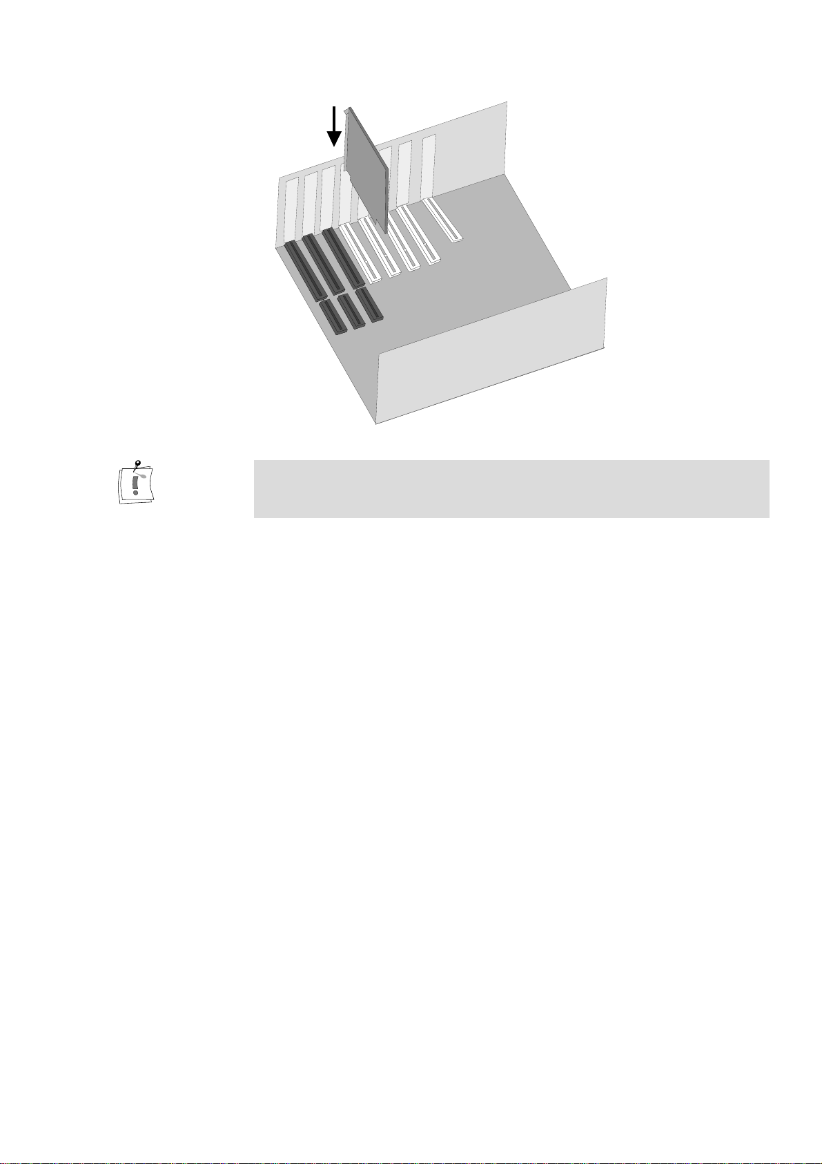
If the board cannot be inserted without problems, do not force the board into
place. The contacts at the connector could bend. Instead, pull the board out
carefully and try again.
7. Screw in the slot bracket.
Screw the slot bracket tight.
8. Reconnect the cables.
Reassemble the computer's casing. Reconnect the cables.
The DV500 hardware installation is completed.
In the next step, you can connect the breakout box and the video devices
as is described in the following chapter and install the software as
described in the chapter „Installing the DV500 Software“.
Chapter 4: Installing the Hardware
13
Page 22
blueBOX and the Video Devices
The following chapter tells you how to connect your video devices to the
DV500 via the blueBOX,
need the appropriate cables.
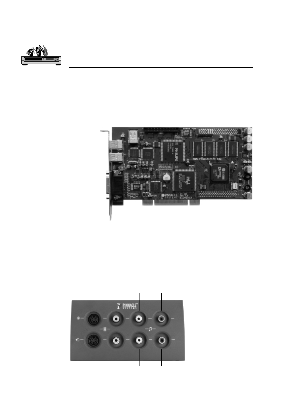
The following illustration shows the DV500 board with its connections:
Connects to DV devices
(1394 connector)
Connects to DV devices
(1394 connector)
Connects to the blueBOX
(26-pin D-type)
Chapter 5: Connecting the
with the computer turned off
. To do so you will
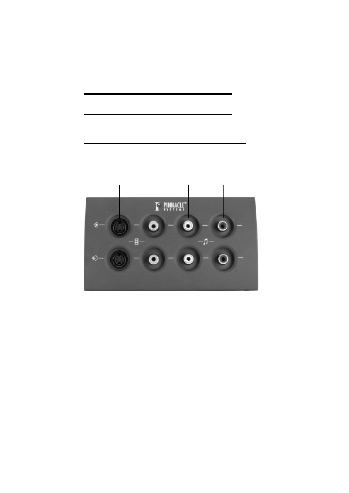
The free connector of the board does not have any function presently, it is
designated for possible future extensions.
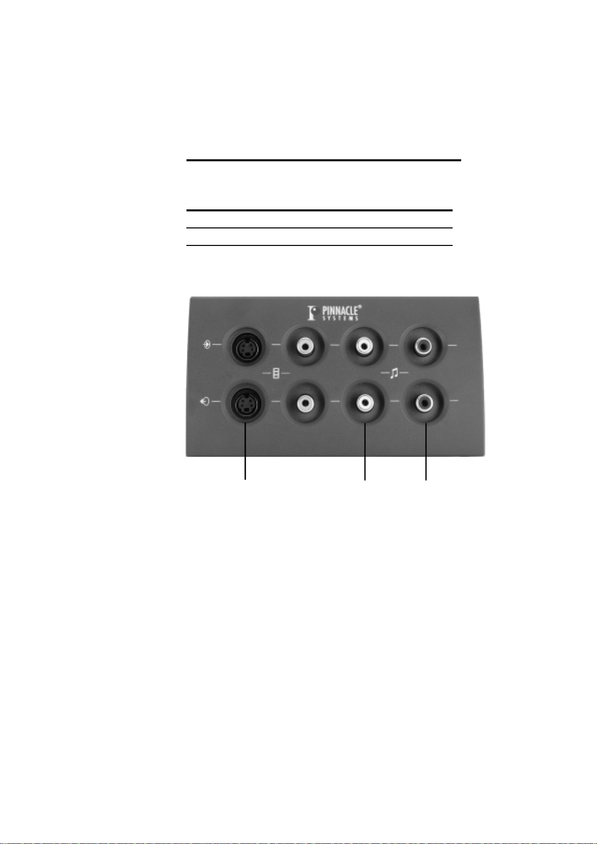
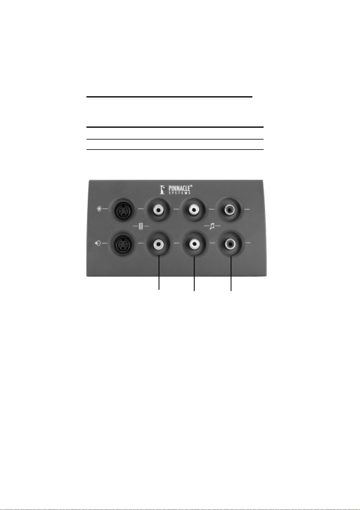
The following illustration shows the connections of the blueBOX:
Video inputs
S-Video
S-Video
Video outputs
Composite
Composite
Audio inputs
Left Right
Left Right
Audio outputs
Pinnacle Systems DV500
14
Page 23

C
ONNECTING THE VIDEO DEVICES
Via the blueBOX you can connect S-Video (Y/C) as well as Composite
video devices to DV500. The blueBOX is connected to the DV500 via the
cable of the blueBOX.
In the following, the options for cabling your video source—referred to as
the
player
that you want to digitize (“capture”) to your hard disk and then edit on your
PC.
—is described. The player provides the video and audio signals
Subsequently, connections to the
device—typically a VCR—that you would like to output your final
production to.
recorder
are explained. The recorder is the
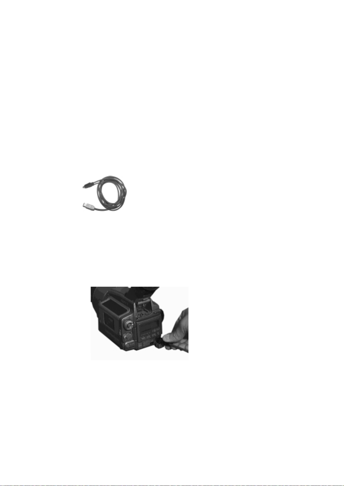
Player: DV device
Devices that connect to the board include any DV or Digital 8 format video
camcorder or recorder that has an IEEE-1394/DV connector. On many
devices, this connector is labeled “i.Link”.
To connect your DV camcorder/VCR to the DV500, use the IEEE-1394 DV
cable included in the package.
1. Connect the IEEE-1394 cable to the DV500.
Connect the 6-pin connector of the IEEE 1394 DV cable to one of the
1394 data ports of your DV500.
2. Connect the IEEE-1394 cable to the DV device.
Connect the 4-pin connector of the IEEE 1394 AV cable to the DV
IN/OUT or the DV OUT connector of your DV camcorder/VCR.
Chapter 5: Connecting the Breakout Box and the Video Devices
15
Page 24
Player: S-Video device
y
Choose this type of connection if your player has an S-Video output.
The following table and the illustration give an overview of the connections:
Player Out blueBOX In
S-Video Input
S-Video Output
Audio Output L
Audio Output R
blueBOX Out DV500 In
blueBOX Cable
¾
Audio Input L
¾
Audio Input R
¾
26-pin D-t
¾
? @ A
c
d
e
pe Connector
Pinnacle Systems DV500
16
If your player is equipped with S-Video outputs as well as with Composite
video outputs, please choose S-Video, as this will provide the highest level
of video quality.
If your player has a Scart connector, you will need an appropriate adapter.
This adapter is available wherever video recorders are being sold.
Page 25

Player: Composite Video device
y
Choose this type of connection if your player has a Composite video output.
The following table and the illustration give on overview of the
connections:
Player Out blueBOX In
Composite Video Output
Audio Output L
Audio Output R
blueBOX Out DV500 In
blueBOX Cable
Composite Video Input
¾
Audio Input L
¾
Audio Input R
¾
26-pin D-t
¾
? @ A
c
②
③
pe Connector
If your player has a Scart connector, you will need an appropriate adapter.
This adapter is available wherever video recorders are being sold.
Chapter 5: Connecting the Breakout Box and the Video Devices
17
Page 26
Recorder: DV device
PAL device:
Many PAL devices sold in Europe usually have only a DV
can be identified by the label DV OUT (and not DV IN/OUT) on the DV
connector. Such devices do
videotape. Note that with DV500, you can of course use the analog outputs
to play your finished DV project to an analog VCR.
NTSC devices
Devices that connect to the board include any DV or Digital 8 format video
equipment that has an IEEE-1394/DV connector, such as Sony Digital
Handycams, DCR-VX1000, DCR-X700, and DCR-PC7. . On many devices,
this connector is labeled „i.LINK”.
If you have not already done so, connect your DV camcorder/VCR to the
DV500. Use the IEEE-1394 AV cable included in the package.
not
support recording of DV data back to
output
. These
1. Connect the IEEE-1394 cable to the DV500.
Connect the 6-pin connector of the IEEE-1394 DV cable to one of the
1394 data ports of your DV500.
2. Connect the IEEE-1394 cable to the DV device.
Connect the 4-pin connector of the IEEE-1394 AV cable to the DV
IN/OUT connector of your DV camcorder/VCR.
The DV output always carries the same signal that you will see on the
analog outputs. It is thus possible to use a DV device on the DV output and
simultaneously connect and use a video monitor and speakers to the analog
outputs.
Pinnacle Systems DV500
18
Page 27
Recorder: S-Video device
y
Choose this type of connection if your recorder has an S-Video input.
The following table and the illustration give an overview of the connections:
DV500 Out blueBOX In
26-pin D-t
blueBOX Out Recorder In
S-Video Output
Audio Output L
Audio Output R
pe Connector
c
d
e
blueBOX
¾
S-Video Input
¾
Audio Input L
¾
Audio Input R
¾
? @ A
If your player is equipped with S-Video outputs as well as with Composite
video outputs, please choose S-Video, as this will provide the highest level
of video quality.
If your player has a Scart connector, you will need an appropriate adapter.
This adapter is available wherever video recorders are being sold.
Chapter 5: Connecting the Breakout Box and the Video Devices
19
Page 28
Recorder: Composite video device
y
Choose this type of connection if your recorder has a Composite input.
The following table and illustration give an overview of the connections:
DV500 Out blueBOX In
c
¾
blueBOX
¾
Composite Video Input
¾
Audio Input L
¾
Audio Input R
26-pin D-t
blueBOX Out Recorder In
Composite Video Output
Audio Output L
Audio Output R
pe Connector
d
e
? @ A
If your player has a Scart connector, you will need an appropriate adapter.
This adapter is available wherever video recorders are being sold.
Pinnacle Systems DV500
20
Page 29
P
LAYER AND RECORDER IN ONE DEVICE
Up to now, player and recorder have been treated as two separate devices.
When editing video with DV500, it is also possible to combine both
functions in one single video device. In this case, connect the device to the
blueBOX as a player
avoid video signal feedback, you should deactivate the option
loopthrough
in the DV500 Control software.
as a recorder, as described above. In order to
and
Video
Similarly, in order to avoid audio signal feedback, you should deactivate the
option
Audio loopthrough
in the DV500 Control software.
Chapter 5: Connecting the Breakout Box and the Video Devices
21
Page 30

C
ONNECTING THE VIDEO MONITOR AND LOUDSPEAKERS
The video display on the PC monitor gives a preview during editing.
Usually, the video is not displayed in full quality, nor does it have the full
size.
In order to check the image and the sound quality during capture, editing
and output, we recommend that you connect a video monitor or TV set,
either with integrated or separate loudspeakers. There are two possibilities:
Connect the monitor to the video and audio outputs of your recorder. In
this case the output signal of DV500 is transmitted to the input of the
recorder (see cabling above), through the recorder and on to the monitor.
Connect the monitor directly to the free outputs of the blueBOX. The
monitor can be connected to the S-Video or Composite Video output of
the blueBOX. If necessary, use an appropriate adapter.
For working with Minerva Impression and to output audio during certain
operations in Adobe Premiere (e. g. scrubbing), you will also need speakers
connected to the audio output of your PC sound board.
Instead of using two pairs of speakers, you may want to connect the audio
outputs of both the DV500 and your PC sound board to an audio mixer. Its
output would then be connected to both the video recorder and the speakers
used for monitoring.
Pinnacle Systems DV500
22
Page 31

Chapter 6:
Installing the DV500 Software
After you have installed the DV500 board in your computer, you can install
the DV500 drivers and software.
Make sure that you have installed Adobe Premiere
DV500 software.
The installation steps for Windows 98, Windows 2000 or Windows NT are
slightly different. Please refer to the corresponding sections:
Installing the Software for Windows NT 4.0 as of page 24.
Installing the Software for Windows 2000/98 as of page 25,
During the installation the following items are copied to / installed on your
hard disk:
The DV500 drivers
Presets for Adobe Premiere
Instant Video
PlugIns for Adobe Premiere
Real-time effects
FreeFX (Windows 98 / 2000 only)
The TitleDeko application
before
you install the
Video SpiceRack
DVTools
The online manual
A short installation guide
Help files and files with information that were not available when the
manual was printed.
The DV500 program group is created and the DV500 Control icon is added
to the Control Panel.
You will find detailed information concerning the installation in the
“Additional information” section as of page 27 in this chapter.
Chapter 6: Installing the Software
23
Page 32

I
NSTALLING THE SOFTWARE FOR WINDOWS
To install the software for Windows NT 4.0, please start your computer, if
necessary start Windows NT 4.0 and insert the installation CD-ROM into
the CD-ROM drive.
Important for Windows NT: Log in with administrator rights.
If the Autostart function has been disabled under Windows NT double click
on
My Computer
drive. The file autorun.exe will be detected. Open this file.
—Or—
icon on the Windows desktop and change to the CD-ROM
NT 4.0
Select the
where
necessary, enter another letter. Click on OK.
e:\
... command in the
Run
represents the driver letter for your CD-ROM drive. If
menu and enter
Start
e:\autorun
,
The installation program
The installation program is started in the language determined by the
Regional Settings (
of the installed Windows version: German, English, or French.
If other Regional Settings than German, English or French are activated on
your computer, you need to select the language in which the installation
should be carried out.
1. If necessary, select language, click
If necessary, select the language in which the installation should be
carried out.
Click on the
2. Follow the instructions.
Follow the instructions of the installation program.
Next
Start
button.
menu,
Settings, Control Panel, Regional Settings
.
Next
)
Pinnacle Systems DV500
24
You will find detailed information concerning the installation in the
“Additional information” section as of page 27 in this chapter.
Page 33

I
NSTALLING THE SOFTWARE FOR WINDOWS
To install the software for Windows 2000/98, please proceed as follows:
1. Switch on computer.
Switch on your computer. Windows is started automatically.
If your computer is configured in such a way, that Windows is not started
automatically, start Windows now.
Important for Windows 2000: Log in with administrator rights.
After Windows starts, the new hardware (the PCI Bridge of the DV500)
is found, and the respective driver will be installed..
2000/98
DV500 Overlay
The
Add New Hardware Wizzard / Found New Hardware Wizard
appears.
2. Click
Click on the
3. Click
In the next window click on the
4. Select
Now specify the folder in which Windows 2000 should search for the
device drivers. Activate the check box CD-ROM drive, make sure all
other check boxes are deactiveted and insert the DV500 CD in your CDROM drive, click the
The DV500 driver will be found.
5. Follow the instructions.
Follow the instructions of the Windows installation program.
The “Pinnacle Systems DV500 Overlay” is found as a new hardware
component.
.
Next
button.
Next
.
Next
CD-ROM drive
button.
Next
, insert the installation CD, click
button.
Next
Next
.
dialog
DV500 E4
6. Click
In the next installation step click on the
The software for the new component will be installed.
7. Follow the instructions.
Follow the instructions of the Windows installation program.
The “Pinnacle Systems DV500 E4” is found as a new hardware component.
8. Click
Click on the
9. Click
In the next windows click on the
Next
Next
Next
.
.
Next
.
button.
button.
Next
button.
Next
Chapter 6: Installing the Software
25
Page 34

10.Click
Next
.
Windows 98
Windows ME
Windows 2000
Windows 2000
The checkbox
Under Windows 98 the “PCI OHCI Compliant IEEE 1394 Host
Controller” will be found. From the list of the selectable drivers choose
the
Pinnacle Systems DV500
Under Windows ME the “Texas Instuments PCI OHCI Compliant IEEE
1394 Host Controller” will be installed automatically. After the reboot
the
Pinnacle Systems DV500
Overlay and the DV500 E4 again).
Under Windows 2000 confirm the following window with
11.Follow the instructions.
Follow the instructions of the Windows installation program.
The Pinnacle software installation program starts. If the installation
program is not started automatically, please read the following section.
Note: Unter Windows 2000 the Pinnacle installation program is not started
automatically. To start the installation program, please proceed as follows:
Double click on
the CD-ROM drive. The file autorun.exe will be detected. Open this file.
CD-ROM
My Computer
is already activated. Click on the
driver. Click on
will be installed (as well as the DV500
icon on the Windows desktop and change to
Next
.
Next
Yes
button.
.
—Or—
Select the
represents the driver letter for your CD-ROM drive. If necessary, enter
another letter. Click on OK.
... command in the
Run
Start
menu and enter e:\autorun, where e:\
The installation program
The installation program is started in the language determined by the
Regional Settings (
of the installed Windows version: German, English, or French.
If other Regional Settings than German, English or French are activated on
your computer, you need to select the language in which the installation
should be carried out.
12.If necessary, select language, click
If necessary, select the language in which the installation should be
carried out.
Click on the
13.Follow the instructions.
Next
Start
button.
menu,
Settings, Control Panel, Regional Settings
.
Next
)
Pinnacle Systems DV500
26
Follow the instructions of the installation program.
You will find detailed information concerning the installation in the
“Additional information” section as of page 27 in this chapter.
Page 35

A
DDITIONAL INFORMATION (INSTALLATION PROGRAM
Selecting Setup Type (installation program)
)
In the
Typical option.
Setup Type
Typical
Installs all components and uses the default settings.
Compact
Skips some components (e.g. online manual) and uses the default
settings.
Custom
Lets you select the components and allows to adjust the settings
individually. You should only choose this option if several versions of
Premiere are installed on your computer, or if your system hard disk is
very slow.
window, Pinnacle Systems recommends to select the
Selecting hard disk (installation program)
If you wish to copy the files to another hard disk / another folder, click on
the
Browse
folder. Click on the Next button to proceed the installation.
The driver software should be installed on the system hard disk and not on
the hard disk for the video files!
... button in the Setup Type window and define the hard disk / the
Selecting components (installation program)
If you have chosen Custom as setup type you can directly choose those
components in the dialog box
DV products software
The option DV500 software includes the drivers for DV500, which must
be installed in order to use the functions of DV500.
System software*
The System software includes DirectX and DirectMedia. If you have
received the note at the beginning of the installation that there is no
DirectX or an older version installed on your system, you should install
the System Software.
Adobe Premiere AddOns
Presets for Adobe Premiere which have been developed specifically for
the DV500 board and the PAL and NTSC standard. These presets are
required for working with Adobe Premiere. If you activate the DV500
Software check box, you can not deactivate the Pinnacle Plugins and the
Pinnacle Effects option.
*
If you cannot select this item, the newest system software is already installed on your computer.
Select Components
, which you want to install.
Chapter 6: Installing the Software
27
Page 36

Video SpiceRack
The Vide SpiceRack software comes with lots of transitions and effects.
Documentation
The User´s Guide is also available in PDF format and can be opened
with the Acrobat Reader. If no Acrobat Reader or an older version has
been installed on your computer, use the Documentation option to install
the current version.
DVTools
DVTools let you scan for clips on your DV tape, add in and out points,
control your DV devices, transfer DV to your hard disk and back to DV
tape.
After having determined the components, click
Next
.
Log in with administrator rights
To install the DV500 under Windows NT and Windows 2000, you
definitely have to log in with administrator rights. This is not necessary for
Windows 98.
Possible additional installation steps
With some hardware configurations the
appears again.
Driver for DV500 Overlay
Click on the
•
Cick
•
Select
•
Follow the instructions of the Windows installation program.
•
.
Next
DV500 Overlay
Next
button.
and click the
Add New Hardware Wizzard
button.
Next
dialog
Pinnacle Systems DV500
28
Driver for DV500 E4
For the installation of the next driver the
dialog appears again.
Click on the
•
Cick
•
Select
•
Follow the instructions of the Windows installation program.
•
Driver for DV500 IEEE 1394
At the end, the driver for DV500 IEEE 1394 is installed automatically.
Follow the instructions of the Windows installation program.
•
.
Next
DV500 E4
button.
Next
and click the
Next
Add New Hardware Wizzard
button.
Page 37

Defragmenting the Hard Disk
If you have problems digitizing video clips you should defragment your
hard disk/s. You find the Windows 98 defragmentation utility under
Programs, Accessories, System Tools, Disk Defragmenter
.
Start
,
If you use Windows 2000, please proceed as follows: Click on
Computer
Properties
Defragment Now...
If you use DV500 under Windows NT, use a tool you can obtain from your
computer store to defragment your hard disk.
, then click right on the disk to be defragmented, then choose
,
Tools
, and under
.
Defragmentation
click on the button
My
Chapter 6: Installing the Software
29
Page 38

Capture, Editing and Playback
The process by which video and audio signals are digitized and then stored
to your hard disk is called capturing. This chapter explains how to use the
features of DV500 video and audio capture that differ from standard Adobe
Premiere operation. Generally, these differences involve settings and
preferences for your DV500 hardware and software. For details on standard
Premiere functionality, refer to the Adobe Premiere User Guide. This
chapter also describes how to play back captured video sequences with
DV500.
Q
UICK CAPTURE CHECKLIST
If you want to capture right now, follow these steps.
Chapter 7:
Function Where and What
1. Connect video source Connect a video source such as a camcorder or VCR
to one of the video and audio inputs of the DV500
breakout box or to the DV connector.
Set the video source into play mode so that it outputs
a signal.
2. Start Adobe Premiere From the
start Adobe Premiere .
3. Select preset To select a Pinnacle preset, click on the
4. Load preset To load the preset, select the appropriate preset, click
on the OK button, click OK again.
5. Project selections
made?
6. Select scratch disk To choose your capture disk, select
IF you have selected a Pinnacle Preset from the
Project Settings
Otherwise, follow the procedure under
Set Recording Options
Preferences/Scratch Disk
File
If necessary, activate the device control, see also
page 38.
Start
menu and the
dialog box, go on to Step 6.
menu. Choose a hard drive and click OK.
Adobe
program group
Load
.
from the Adobe Premiere
button.
Load
Pinnacle Systems DV500
30
7. Bring up movie Select
Capture
8. Begin capture Start your source tape and click on
in the
9. End capture To end capture, press the <Escape> key.
File, Capture
window appears.
Movie Capture
Movie Capture
and
window.
Record
. The
Movie
Page 39

C
APTURING VIDEO IN DETAIL
Loading a Preset
The presets included with DV500 contain settings that guarantee an optimal
operation of DV500 and Adobe Premiere . We strongly recommend that you
load a Pinnacle preset every time you start Premiere . If you select the
settings manually, please note that Premiere will allow you to select
resolutions, frame rates and other options that DV500 cannot support.
1. To load an appropriate preset, start Adobe Premiere via the
and the program group
The
New Project Settings
2. Click the
The
Load Project Settings
button in the
Load
Adobe
.
window appears:
New Project Settings
window appears.
dialog box.
Start
menu
Chapter 7: Capture, Editing and Playback
31
Page 40

3. Select one of the settings that have been installed for your DV500 editing
board.
Please make sure that your selection between PAL and NTSC matches
the video equipment that you will be using.
4. Click OK to use the DV500 setting. The Premiere project settings are
now optimized for working with the DV500 editing board. You return to
the
New Project Settings
window.
5. Click OK to finish the loading of the preset.
The supplied presets guarantee best results and an optimal quality. If you do
not use these presets and manually choose settings that the DV500 hardware
does not support, editing will not work correctly.
The supplied presets automatically set the output resolution, rendering field
order, audio format and other Adobe Premiere parameters to the correct
values for working with your DV500 editing board.
Preparing for Capture
Before you capture video under Adobe Premiere , please select the capture
drive. This is the drive to which your AVI files will be written. It should be
a separate hard disk that is fast enough and offers enough free space for
digital video recording.
1. To choose your capture disk, select
Device Control
The
Preferences
from the Adobe Premiere
dialog box will appear, allowing you to choose the
Preferences
menu.
File
location for your files:
2. Select fast hard drives for all three types of files,
Video Preview Temps
and
Audio Preview Temps
If you use a DV device you should absolutely select
control
as
Device Control
.
and
Scratch Disk /
Temp/Captured Movies,
and click
OK.
Pinnacle device
Pinnacle Systems DV500
32
Page 41

We recommend that you store all video files and Adobe Premiere project
files along with their temporary video clips on one or more separate drives
reserved for video editing. Storing any of these files on your system drive
may result in unsatisfactory performance or dropped frames during capture
or playback. To check the performance of your hard disks, please start the
DVExpert tool in the DV500 program group.
Setting the Recording Options
Before capturing a video clip, you should check the capture settings. For
this, select the
menu and the commands
File
Capture
and
Movie Capture
.
The
Movie Capture
click into the
open the DV500 Control.
The settings dialog is described in detail in the “Pinnacle Control” chapter in
this User's Guide. In addition, clicking the
same information.
window appears. Now use the right mouse button to
Movie Capture
window and select the
button will also display the
Help
Settings
... command to
Analog devices
only
For capture, please review the following items and make changes as
appropriate:
Video
Select the video input that your video source is connected to and make
adjustments for brightness, contrast etc.
Video
Select the video standard, and the frame size.
Audio
Select the audio input and the audio capture format. In addition, the
audio recording level may be adjusted here.
Now click OK to close the dialog.
input tab
format tab
input tab
Chapter 7: Capture, Editing and Playback
33
Page 42

The file type for capturing (AVI) can be changed by opening the Premiere
Project
called
menu and choosing
Capture
Format.
Settings
and
Capture
. Here, open the list box
Capturing the clips
We recommend that you disconnect from any network prior to a video
capture session, as network traffic may result in dropped frames.
1. Click the
Capture commences. The video is displayed as it is captured on your
Record
button at the top of the
Movie Capture
window.
monitor and PC.
2. Watch the display in the lower left corner of the
during the capture process. If you notice that
any
Movie Capture
frames are dropped,
window
press the <Esc> key to halt the capture process.
Press the <Esc> key to end the capture session when you have captured
the desired amount of video.
The movie window appears.
3. Select the
Tip:
Save your file to the root directory of your video disk. Saving it
menu and the
File
command to save the file.
Save
somewhere else will result in the file being copied to the new location.
This can be time-consuming.
4. Close the
Clip
window.
5. Capture a second clip in the same way as you captured the first one.
6. Close the
Capture
window.
Pinnacle Systems DV500
34
Page 43

E
DITING THE CLIPS
Adobe Premiere is a powerful editing application that usually provides
several options on how to achieve a certain task, allowing you to pick the
method that best matches your personal way of working. In the following,
we describe one way of doing things - please refer to the Premiere User
Guide for much more detailed information.
To edit the captured clips, activate the
1. Click right and select the commands
2. If necessary, change to the hard disk and into the directory where you
saved the files you captured.
3. Select the files and click
The selection of files works as follows:
To select a single clip
−
button.
To select several clips in a row
−
left mouse button, press the <Shift> key and keep it pressed, click on
the last clip pressing the left mouse button, release the <Shift> key.
To select several clips out of order
−
the left mouse button, press the <Ctrl> key and keep it pressed, click
on the next clip by pressing the left mouse button, etc., then release
the <Ctrl> key.
4. Drag the first clip into the left
5. If desired, set in and out points.
Open
: click on the file by pressing the left mouse
Project
.
: click on the first clip pressing the
Monitor
window.
Import
and
: click on the first clip pressing
window (
.
File
Source
window).
6. Drag the clip into the right
The captured video clip automatically appears in the timeline.
7. Repeat the steps 4. - 6. to place the second clip in the timeline.
8. If you want to add a transition, drag the second clip into the
track.
9. Now, drag a desired transition from the
Transition
Important:
they do not require rendering. All others must be rendered before they can
be played back.
10.To add a filter to the video clip, select the clip, click right and select
Filters
For detailed information of how to select and use transitions and filters,
please refer to the “Transitions, Filters and Superimpositions” chapter of
this User's Guide.
track. To specify the properties, double-click the transition.
The transitions named “Pinnacle ...“ are real-time transitions,
. The filters named Pinnacle can be done in real-time.
Monitor
Window (
Transitions
Target
window).
windows into the
Video 1B
Chapter 7: Capture, Editing and Playback
35
Page 44

P
LAYBACK
Previewing the Project
You have several possibilities to preview the clip in the target window:
You can scrub in the timeline using the cursor in the time ruler.
If the timeline or monitor Window is activated, you can start the preview
from the current cursor position pressing the <space bar>. Pressing the
<space bar> again stops the preview.
You can start the preview clicking on the
window. Clicking on the
Important: Only real-time effects such as the Pinnacle transitions can be
seen in the preview. All other effects will show the current video frame and
a red cross on playback until they are rendered by setting the work area
appropriately and pressing <Enter>. (see the “Rendering the Project” section
as of page
Fehler! Textmarke nicht definiert.
button stops the preview.
Stop
button of the
Play
).
Target
Setting the Output Options
Before playing or rendering the project you should review and change the
output settings using the DV500 Control. To do so, click right on the
Video
The DV500 Control window appears.
window and choose the
Settings...
command.
Instant
Pinnacle Systems DV500
36
The settings dialog is described in detail in the “Pinnacle Control” chapter in
this User's Guide. In addition, clicking the
same information.
button will also display the
Help
Page 45

Click on the
video quality for the selected output and adjust the audio level. Click on
to close the dialog.
The Volume slider in the output settings sets the upper limit of the audio
level that gets sent to the analog outputs. In addition, the speaker icon button
in the Premiere Monitor window allows you to attenuate or mute the audio
output.
These options are not available if a DV device is connected. With a DV
device you can activate the 16:9 DV output format option.
O
UTPUTTING THE PROJECT
To output the project,
1. Select the work area so that it covers the parts of the project that need
rendering (and that you want to render now).
2. Press the <Enter> key.
Output
tab. Here, you can adjust an output filter to optimize the
OK
Adobe Premiere asks you to save the project.
3. Click the OK button.
4. Change to the drive and into the directory where you want to save the
project. Use the drive that is reserved for video files.
5. Enter the file name and click on the
The
Building Preview
displayed. First the video data, the transitions and the filters are rendered
(Pinnacle Systems’ transitions and effects need not to be rendered). Then
in a second render process the audio data are rendered.
After the render process, playback will start automatically at the beginning
of the work area. You will now see
effects.
windows appears. The estimated remaining time is
all
button.
Save
effects, even the non-real-time
Chapter 7: Capture, Editing and Playback
37
Page 46

D
EVICE CONTROL
For a list of compatible DV devices, please refer to our website under
http://www.pinnaclesys.com
The DV500 board can control DV devices connected via the 1394
connection, and can query information from the device like time code, for
example. The device control function of the DV500 is capable of controlling
DV devices that are connected to the board via the 1394 cable.
Before you begin controlling your DV device, you must configure the
device control and Premiere for your device.
.
1. In Premiere, click the
Select the
Scratch Disks / Device Control
2. In the device control list box, select the entry:
menu and then the
File
Preferences
command.
command.
Pinnacle device control
Operating the device control
The 1394 device control of the DV500 supports the following functions:
Frame forward, frame backwards
Export to DV tape, insert edit
*
*
.
Position information (the time code)
Locate commands , seeks to a specific time code
Basic functions
(Stop/Rewind/Fast Forward/Playback/Pause)
Batch capture, in combination with any capture plug-ins
Jog Shuttle functions
The device controls are accessible in various Premiere windows. Consult the
Premiere user manual for details on how to control a device from Premiere.
*
These functions are not supported by all DV devices.
Pinnacle Systems DV500
38
*
Page 47

Export to DV tape
For record and insert/assemble edits you need DV devices that support these
functions. Consult your video recorder/camcorder user manual to find out
which functions your device supports. The device control will determine
your device's scope of functions and will only offer those functions that
your device supports.
Although the device control supports functions such as record and insert
cuts, no guarantee of clip playback precision can be given. It is Premiere
that plays the video clip, and not the DV500 device control. Please consult
Adobe Premiere's technical support if you should find there are irregularities
in video playback.
Under Premiere, the DV500 supports export of video data to tape.
In Premiere, click the
•
Export and Export to Tape
menu.
The following dialog box appears:
command in the
File
Chapter 7: Capture, Editing and Playback
39
Page 48

Certain device control options can be activated.
Activate recording deck
Select the
Activate recording deck
option if you want to use the device
control to synchronously set the connected DV device to the record
mode. This is required to record video data to tape.
Print to tape options
These settings allow a frame accurate insert/assemble cut if the
connected DV device is supporting this function. Otherwise this
option is greyed.
Time code
You can enter a start time code that is used for the current project.
Further, you have the possibility to adjust the desired target time code
yourself by using the device control buttons. Just search the position
on the tape where you want to insert the project.
Preroll
The
Preroll
field allows you to fine tune the synchronous start of
playback and recording.
Once you have made the required settings, Premiere switches to the
playback mode to prepare the required operations and starts playback.
During operation your PC screen will be blacked. After playback, Premiere
switches back to the edit mode. You may have to repeat the settings just
defined because they are not stored.
Adjusting the device control accuracy
You can use the following steps as a guideline for fine tuning the export to
tape function.
Stripe a DV tape, the tape should contain continuos time code. Switch
your DV device into the
Camera
mode, rewind the tape and while the
lens is darkened push the record button until the tape is completely
recorded.
Select Export-to-tape as described above.
Enter a start time code. Save the in and out time code to a piece of paper
Hit Enter to start operation.
After the export-to-tape operation is complete use the device control (you
must select Movie capture) or the remote control to seek to the start time
code. Check the discrepancy between the first recorded frame and the
desired tape location. This difference should be used the next time you
repeat this operation in the preroll setting.
Check that recording started with the first marked frame of your project.
Check that recording stopped at the out-time code.
Repeat this procedure until you find the preroll value that works the best.
Pinnacle Systems DV500
40
Page 49

If you find that recording started or ended inaccurately we recommend that
you use black frames at the beginning and at the end of your video
production to ensure that the total production is recorded.
Note that the export-to-tape accuracy depends on the DV camcorder or VCR
that is used. Pinnacle Systems cannot guarantee that this function is
supported by all DV devices.
Discrepancies
Suppose that you wanted to start the cut at time code 01:00:00:00. What was
the frame number at the start of the cut after the project was transferred? If it
was at 01:00:00:01 or more, the clip was started too early. Therefore, you
should enter a smaller number of frames under “Pre-roll”. Repeat the test
until you arrive at a satisfactory result.
If the first frame at the start of the cut was black or if you saw repeated
frames, the clip was started too late. In this case, you must set a higher
number of frames for the “Pre-roll”.
Premiere and time code
Internally, Adobe Premiere assigns frame numbers to your recorded clips
instead of genuine time codes (this applies to all versions of Adobe
Premiere). Frame numbers are random, automatically incremented numbers
that, above all, facilitate the work of programmers. However, as one and the
same frame number may correspond with one of three different time code
values, depending on the time code format used, problems may be
encountered if the correct time code format is not set. This may be relevant
in the following situations:
You manually enter a batch list with the wrong timed code format, or
You use Premiere's logging function without device control in the video
recording window (Movie Capture).
The time code format in the recording window does not match the
current tape format that is currently being logged.
This may lead to various errors like the following:
“Time code not found” error message
The time code on your clip is offset by a few seconds
Recorded clips begin with a wrong time code
The reason for this is fairly basic. If you choose a time code of 01:00:00:00
for the starting point, Adobe Premiere may interpret this value depending on
the format of the digitized video:
NTSC (NDF time code) 108,000 frames
NTSC (DF time code) 107,892 frames
PAL 90,000 frames
Chapter 7: Capture, Editing and Playback
41
Page 50

A new feature in Premiere is the ability of displaying the time code of your
clip and monitor windows in different ways, some of which may be
confusing. In turn, this may lead to errors if you attempt to calibrate your
time code discrepancy or to manually enter a batch capture list. Premiere
allows you to adapt the time format of the monitor or clip window.
However, this
does not
affect the video recording window. This is a general
setting that does not change automatically when you load a clip with a
different format. The fact that the time base of a clip can also be displayed
incorrectly makes it difficult to determine the time code format of a clip. If
you wish to determine the actual time code format of a clip, you must call
up the
Properties for
command from the
menu while the clip in
File
question is displayed in the monitor or the clip window. You will find
further information on this topic in the Adobe Premiere manual.
DV time code
Drop frame
time code
DV devices use a Drop Frame or DF time code (NTSC only). It cannot be
set to a specific default, i.e. new tapes always begin at 00:00:00:00.
Nevertheless, this is exact and returns clear values for single frames. When
working with DV material, select “Drop-frame time code” in the Premiere
project settings.
NTSC video (the US standard) is based on 30 frames per second almost.
The exact frame rate is 29.97 frames per second, which corresponds to a
mismatch of 3% per second. This is why video engineers developed the DF
system, where 2 frame numbers each minute – with the exception of each
10th minute – will be skipped. Actual video frames will not be skipped, just
the numbers in time code used to count them. One important reason for the
use of the DF time code is that the timing of long videos will be more
precise.
In figures, it looks like the following:
Non Drop Drop
00:01:00;00
00:01:00;01
00:01:00;02
⇒
00:01:00;03
⇒
Pinnacle Systems DV500
42
Please note that this applies only to every 1st, 2nd, 3rd, 4th, 5th, 6th, 7th, 8th and
th
minute, but not to the 10th, 20th, 30th, 40th, 50th or the 0 minute.
9
Page 51

Chapter 8:
DV500 Control
Starting the Pinnacle Control from the Control Panel
You have two possibilities to start the Pinnacle Control tool:
Click the
double-click the Pinnacle Control icon
Click the
Control
Important: Settings that you change from the Windows Control Panel or in
the Pinnacle program group (Pinnacle Control) are global settings. The
settings take effect when video clips are played back, for example, via the
Media Player or the DV500 is used with other applications.
The control program is also available to you within Adobe Premiere. The
settings that you make here, for example, by selecting a Pinnacle Preset,
apply only in Adobe Premiere and are saved with every project.
.
Menu, the commands
Start
menu and the commands
Start
Settings
and
Pinnacle, Tools
Control Panel
and
Pinnacle
and
Starting the DV500 Control from Adobe Premiere
To start the DV500 control under Adobe Premiere:
For the input options,
click with the right mouse button in the
Capture, Movie Capture
select the
Configure
Project
button.
menu and the
) and select the
Settings, Video
Movie Capture
Settings
... command, or
command and click the
window (
File
menu,
For the output options,
click with the right mouse button into the Instant Video window and select
the
Settings
The DV500 Control offers the following tabs to modify your settings.
Video input
Video format
Audio input
Output
General.
The tabs may offer different options—depending on the connected video
device (S-video / Composite video or DV)
... command.
Chapter 8: DV500 Control
43
Page 52

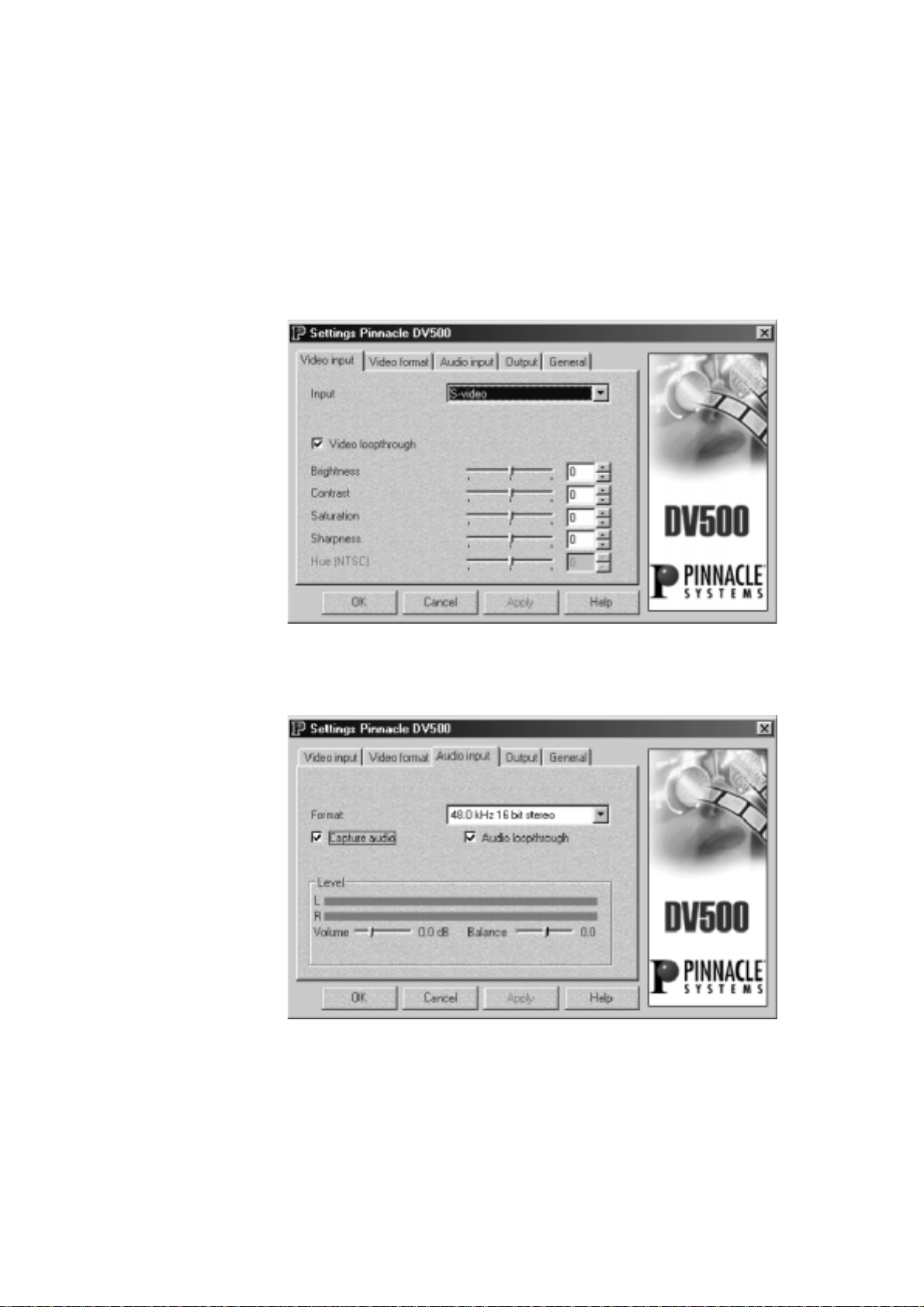
S
ETTINGS
—V
IDEO INPUT
The video input tab allows you to specify all settings concerning the video
inputs.
Input
Determine the connector of the connected video source:
or
DV device
checkbox.
Several sources can be connected at the same time, but only the selected
signal will be digitized.
Video loopthrough
The
Video loopthrough
the same time the recording device, i.e. it is connected to the video input as
well as to the video output, you need to deactivate the
checkbox in order to avoid video feedback.
If a DV device is selected, this option is not available.
Brightness / Contrast / Sharpness / Saturation / Hue (NTSC)
Allows you to modify the
Saturation.
This applies to analog sources only. If a DV device is selected, these options
are not available.
. If the DV device is known, its name will appear in the
checkbox is enabled by default. If your player is at
Brightness
Under NTSC you can additionally change the
, the
Contrast
S-Video, Composite
Video loopthrough
, the
Sharpness
.
Hue
and the
Pinnacle Systems DV500
44
Page 53

S
ETTINGS
—V
IDEO FORMAT
Via this tab you determine the video format.
Video standard
Here, you determine the video standard of the connected video source: PAL
or NTSC. The default setting is the video standard that you have selected
during the installation of DV500. Note that products bought in the USA
only support the NTSC standard.
Frame size
The full frame size (checkbox
size of 720 x 576 pixels for PAL and a frame size of 720 x 480 pixels for
NTSC. This size is the standard resolution for MPEG2-coded video and
provides best results when your production target is DVD or MPEG2-CD.
Cropping
If you enable the
be digitized (PAL: 704 x 576, NTSC: 704 x 480). This is useful if your
video source does not supply the full 720 pixels horizontally, as it prevents
black vertical lines at the sides of the video image, which can be especially
annoying when using push transitions or picture-in-picture effects.
When using cropping, you can still export your project for DVD or MPEG2CD production and the image size will be recalculated to the standardized
720x576 or 720x480 resolution. However, this will increase the rendering
time for the export and may result in a loss of quality.
Cropping
Cropping
checkbox, a slightly smaller image section will
not
activated) offers you a frame
Chapter 8: DV500 Control
45
Page 54

AVI file format
AVI 1.0
If you want to import an *.avi file into an application that does not support
the
OpenDML
OpenDML
If you activate the
exceed the 2 GB limitation.
option, activate the A
OpenDML
format, you can capture *.avi files, which
VI 1.0
checkbox.
S
ETTINGS
—A
UDIO INPUT
This tab allows you to specify the necessary audio input settings.
Format
Here, you select the format for audio recording of the video sequence.
Analog source
DV source
Pinnacle Systems DV500
46
For DVD select 48 kHz 16 bit stereo. For MPEG2-CDs, 44.1 kHz 16 bit
stereo is more appropriate, as some PCs may not be able to play back 48
kHz audio.
If you have selected a DV device as video input, the audio format is
adjusted dynamically to the format of the DV devices. A preliminary
selection is not possible.
Capture audio
Activate the
audio. Deactivate the checkbox for capturing without audio.
Capture audio
checkbox if you want to capture the clip with
Page 55

Audio loopthrough
(for analog sources only)
The
Audio loopthrough
the same time the recording device, i.e. it is connected to the audio input as
well as to the audio output, you need to deactivate the
checkbox in order to avoid audio feedback.
DV Channel
If there is no DV signal received by DV500, this option will be greyed.By
selecting the option button 1 or 2, you determine whether the input signal
will be recorded from channel 1 or channel 2. Note that DV devices provide
two audio channels only if you selected 32 kHz 12 bit audio on your DV
equipment at recording time.
Level
Volume / Balance
Moving the sliders Volume and Balance you can select the audio input level
and balance. It should be set so that the VU meter stays in the green and
yellow areas.
(for analog sources only)
(for 32 kHz only)
checkbox is enabled by default. If your player is at
Audio loopthrough
S
ETTINGS
Output
(analog device)
—O
tab
Peakmeter
If an analog input is selected a peakmeter displays the audio level.
UTPUT
The
Output
audio. The appearance of the
video device: analog (S-video / Composite video) oder digital (DV device).
tab lets you determine the output settings for video as well as for
Output
tab varies according to the connected
Chapter 8: DV500 Control
47
Page 56

Output filter
Here, you select if the output filter is optimized for the S-Video or the
Composite video output. Set this option according to the output you
connected your recorder to. Note that all outputs will always show the video
signal, but the one selected here will provide the best-quality signal.
When outputting to a DV device, this option will not influence the filtering.
Test picture
If the checkbox test picture is activated the internal test picture of the
encoder will appear on the S-Video and composite video outputs and
indicate the correct function of DV500.
The test picture will never appear on the DV output.
Checkbox Real-time
If you deactivate the real-time option, the real-time effects have to be
rendered. You should only deactivate the real-time effects if you realize that
the project playback cannot be done jerkyless.
Output
tab
(DV device)
Volume
Volume / Balance
Moving the sliders
Volume
and
Balance
you can select the audio output and
balance level. Both sliders can be moved independently of each other. The
set level will be displayed.
Pinnacle Systems DV500
48
16:9 DV Output format
If you activate the
16:9 DV output format
checkbox, the video is output in
the 16:9 DV format (”wide-screen format”).
Page 57

S
ETTINGS
—G
ENERAL
This tab allows you to determine the overlay settings during recording and
playback.
Mode
Here you can determine the overlay mode during recording and playback.
Overlay Surface
As the overlay surface can be produced with a considerable less amount
of system resources and additionally without any limitations to the
resolution, you should generally—if your graphics board supports it—
activate the
Primary Surface
Use this option if your graphics board does not support the Overlay
Surface or if you notice that buttons or other screen elements to not get
displayed correctly.
Off
There is no video display on the PC screen during recording and
playback.
Pinnacle logo
If you activate the
displayed during recording and playback. This setting is available only if
you selected
PC screen only, it will not show on the video outputs nor will it get recorded
with the video when you capture.
Overlay Surface
Pinnacle lo
Overlay Surface
.
go checkbox, the Pinnacle logo will be
as the mode. Note that the logo is seen on the
Chapter 8: DV500 Control
49
Page 58

DV Overlay Provider
*
(connected DV device only)
Here, you determine where the overlay appears. Select one of the following
options:
DV software codec
The overlay will be displayed via the software.
S-Video
The overlay is taken directly from the S-video output of the video source.
Composite
The overlay is taken directly from the Composite video output of the video
source.
*
This option is not available if you open the
Pinnacle Systems DV500
50
General
tab via the Instant Video window.
Page 59

Chapter 9:
Working with DV material
This chapter introduces the step-by-step process of capturing DV clips from
tape using DVTools, editing DV using Adobe Premiere, and printing DV
back to tape. It also explains how to capture a single frame from your DV
tape. The combination of the DVTools and Adobe Premiere lets you get the
most out of your DV footage.
Preparations
M
AKING MOVIES
Before you start working with DV material it is advisable to check your
system performance using the DVExpert. The DVExpert is located in the
DV500
disk being tested should be defragmented. If you use more than one hard
disk in your system, you should test them all and use the hard disk with the
fastest data rate.
For more information on the DVExpert, please click on the help button in
the DVTools.
Note that the DVTools require at least a 16-bit color resolution and an 800 x
600 resolution. If your display is set to fewer colors, an error message will
appear after starting the DVTools.
In planning and capturing your movie, use the DVTools. DVTools allows
you to scan the DV tape, store clip locations, view the individual clips, redefine and edit clip in points and out points (i.e., start and end markers) and
re-order clips. Once you have completed these steps, you can create separate
AVI files for each clip. After these AVIs have been created you can use
Adobe Premiere to add titles, transitions and special effects. You can then
output the final DV back to DV tape or to conventional analog tape.
Program Group. In order to provide you with realistic results, the
The difference between scanning and capturing
Scanning the tape does not capture the video and save it to the hard drive.
Scanning merely identifies all the clips on the tape so you can see which
clips are candidates for your final video, and which aren’t useful at all.
Capturing, on the other hand, saves the digital video on the hard drive. At
that point, with the digital video on your computer’s hard drive, you can edit
the clip using Adobe Premiere.
Neither scanning or capturing modifies your original videotape in any way.
Your original shots remain in their original form and quality.
Chapter 9: Working with DV material
51
Page 60

Some remarks on shooting DV footage
When shooting DV, you can use as many DV tapes as you like. DVTools is
capable of keeping track of as many DV tapes as you wish to scan. When
you scan the video tape later, the software will automatically detect the start
of a clip at each place where you started the recorder. Conversely, those
places where you stopped recording will automatically be detected as ends
of clips.
When shooting video footage, make sure the camcorder is running in
C
amera
mode
.
Checking preferences in DVTools
Before using the DVTools to capture your video footage, it is advisable to
check the preferences with regard to your television standard and some
recording parameters. In Western Europe (except for France), the PAL
standard is used; the standard used in the USA is NTSC.
To check the preferences in the DVTools, proceed as follows:
1. Launch the DVTools.
Click
Program Files
and click on
The
Capture Gallery
DVTools
in the
appears.
menu. Select the program group
Start
.
DV500
Pinnacle Systems DV500
52
Page 61

3. Checking the TV standard.
In the
Capture Gallery
, select the
menu and the
Tools
Preferences
item. This dialog will be displayed the first time you launch DVTools.
The program can automatically detect the video standard if the DV
device is connected to the card and is switched on. You must not
overwrite this setting.
3. Choose your preferred capture method
You can select between a single pass capture and a multi pass capture.
Default is single pass capture since your PC system should be fast
enough to capture DV footage in one pass. If you find too many dropped
frames on the capture you might select the multi pass capture method.
4. Select the capture drive.
Under
Trim point based capture
, select the hard drive and the directory
where you want to save the video. Please verify that enough storage
space is available on this drive.
5. Select the audio channel.
DV devices support two audio channels on a 32kHz setting. Select the
channel from which you want to capture the sound.
6. Select an appropriate value for the
Length of blank
. Click OK.
When scanning a DV tape containing long blank sections where no DV
footage has been recorded, the DVTools might abort the scanning
process in the middle of such a pause because it assumes that the blank
section is the end of the recording. To ensure that the DVTools continue
to scan the tape, you can enter a value (in seconds) under
blank.
This value determines the maximum length of a blank section
Length of
which the DVTools will accept as a pause but not as the end of a
recording.
menu
Chapter 9: Working with DV material
53
Page 62

Scanning a DV tape for clips
Once you have set the preferences, you can use DVTools to scan your DV
tape(s) for clips. A clip is defined as a video sequence located between an in
point (start of take) and an out point (end of take).
To scan a DV tape for clips, proceed as follows:
1. Connect DV equipment.
If you haven't already, connect your DV camcorder or DV video recorder
to the DV500 board.
2. Turn on your DV equipment.
Turn on your DV camcorder or DV video recorder. Make sure that your
DV camcorder is running in
3. Insert DV tape.
If you haven't already, insert the DV tape in your DV equipment.
4. Scan DV tape.
You can start the scanning process in three ways:
Click the
(see icon).
Tape Scan
button in the right section of the
VTR
mode.
Capture Gallery
Right-click into the
of the Capture Gallery) and select
From the
It is also possible to scan the tape manually (
the video simultaneously.
The DV tape is then rewound to the beginning and the DVTools display a
dialog box showing the progress of the scanning process. To abort this
process, click on
5. Enter a name and description for the DV tape or rescan the tape.
After the tape has been rewound, DVTools will identify the tape.
If the tape is unknown to the tape database, the program will prompt
you to enter a name and a description for the tape. After you have
typed in the information, the tape description will be stored in the
database.
If the tape is already known, the program will allow you to abort the
tape scan or to rescan the tape. The clips from the previous scan are
remembered and you will be promoted as to where to start the new
scan. This is helpful if you have recorded new footage to a tape you
have previously scanned. You can scan in the new scenes, updating
the existing scan gallery, without having to re-scan the entire tape.
Tools
DV Explorer
menu, select
Cancel
.
(mainly white area in the left section
Scan DV tape...
Scan DV tape
.
Live capture
) and capture
Pinnacle Systems DV500
54
Page 63

Next, DVTools scans the DV tape for clips. The scan process takes as
much time as it would take to play back the video footage on your tape.
For example, a 30-minute tape will take approximately 30 minutes to be
scanned if the tape is completely filled with video information. If the tape
only contains 15 minutes of video data the scan will need approx. 15
minutes.
Once the software has finished scanning the tape, a window appears in
which all the clips found on the video tape are depicted as „poster
frames“ (the first frame in a clip). This
any time after you scanned a tape.
Tape Gallery
will be brought up
6. Scan additional DV tapes if necessary.
If you want to use several video tapes for your movie, have DVTools
scan for clips as described above.
Viewing clips and adding trims
To view your DV at full-screen size, a television set or video monitor must
be connected to your DV camcorder or DV video recorder. There is also a
preview window in the
small thumbnail window with a reduced resolution.
To view clips, proceed as follows:
1. Open DV tape (if necessary).
If the
Tape Gallery
already, double-click a database name in the
question must be in the DV camcorder.
A
Tape Gallery
depicted by the first frame (poster frame) of each clip.
DV Device Controller
with the clips of your video tape is not displayed
then appears in which all the clips on your video tape are
that plays back your DV in a
DV Explorer
. The tape in
Chapter 9: Working with DV material
55
Page 64

2. Playing back clips.
To view a clip, first double-click on the desired clip. The
window will then appear
The
Clip Info
window displays the title, the time code, and the trim
.
Clip Info
points (if there are any). If you wish to do so, you can enter a description
for your clip.
To rewind or forward the tape to the position where the clip is located,
click on the
(eye) button. The DV device will take a while to find the
start of the clip.
Pinnacle Systems DV500
56
Page 65

The
DV Device Controller
will appear. You will know that the tape is
positioned to the start of the clip when the time code displayed at the top
of the window is identical with the clip start displayed at the bottom of
the window.
The
DV Device Controller
lets you control your DV device. The video
tape does not automatically stop when it reaches the end of a clip. To
pause the playback, click on the
Pause
button.
3. Choose the clips you want to capture.
Once you have „sifted through“ your video footage, you can choose the
clips you actually want to capture. To do so, drag the desired clips from
*
the
Tape Gallery
and drop them in the
arrange the clips in the
Capture Gallery
Capture Gallery
in any order.
. You can
*
Drag & Drop:
Left-click the desired element. Hold the mouse button down and drag the element to the desired position. To
“drop” the element, release the mouse button.
Chapter 9: Working with DV material
57
Page 66

4. Add trims.
Sometimes you may not want to use an entire clip, but rather only part of
a clip. In that case, you can edit the clip in question using the
Controller
.
DV Device
You can define the in point and out point of a clip using the (in
point) and
(out point) buttons. You can either click on the buttons
during playback, or pause the tape at the desired location and then click
on these buttons. You can also forward and rewind the tape using the
slider control at the bottom of the
DV Device Controller
window (jog-
shuttle function). Once you have finished inserting the points in the clip,
click
(
Apply)
to save the trim points.
The original trim points are still stored in the clip database and can be
restored at any time by clicking on
.
Pinnacle Systems DV500
58
5. Save the
Save the
select the
Capture Gallery
Capture Gallery
Save as...
the extension *.sto.
file.
file with the added clips and edits. To do so,
option in the
menu. These files are saved with
File
Page 67

Capturing DV (generating AVI files)
Now that you have selected the clips for your movie, you can generate AVI
files.
To generate AVI files from the clips, proceed as follows:
1. Open the
If you have not done so already, open the
capture. To do so, click on the
Capture Gallery
2. Check file size.
The status bar at the bottom of the
the total duration, and the total size of the AVI files that will be
generated. If you like to verify that you have enough disk space for
capturing the clips from this Gallery, click on your drive in Windows 95
Explorer
DVTools will check if there is enough disk space available before
capturing.
3. Capture AVI files.
To create AVI files from the clips in your
Capture
4. Enter file name and directory.
Capture Gallery
. Here you can select the
. The free space on your hard disk will be displayed. However,
button located on the right-hand side of the
.
Capture Gallery
menu in the DVTools and select
File
Capture Gallery
Capture Gallery
Capture Gallery
shows the clip count,
you want to
(*.sto file).
, click the
Capture Gallery
Open
.
If you do not want to use the default drive you chose in the
dialog, enter a file name and choose a directory to which you want to
copy the AVI files. All clips located in the
captured. The AVI files will be numbered according to the order of
capturing.
DVTools use a unique technology, in multi-pass capture mode, allowing
lossless capture also on slower computer systems. For that reason, DVTools
may search the DV tape one or more times to retrieve dropped frames.
Capture Gallery
Preferences
will then be
Chapter 9: Working with DV material
59
Page 68

Editing AVI files using Adobe Premiere
The DVTools allow you to directly launch Adobe Premiere without having
to do this from the Windows
If you want to output your AVI file to the DC30 board, you must select the
Optimized display for DC30
To edit your AVI file(s) using Adobe Premiere, proceed as follows:
1. Start Adobe Premiere.
To start Adobe Premiere, click on the corresponding button on the righthand side in the
your system, this button will be disabled.)
2. Select a Project Preset.
Select an appropriate Project Preset, depending on whether you are using
PAL or NTSC and on whether you want to output your final DV file to a
DV tape or to an analog video tape via DC30.
3. Import AVI file(s).
Capture Gallery
menu.
Start
option in the DV Configuration tool.
. (If Adobe Premiere is not installed on
To import one or more AVI files, go to the
menu commands
4. Edit AVI file(s).
At this point you can add effects and process your video. If necessary,
select the display mode for all frames of the video clips under
Construction window options, Track format
5. Make a movie.
Use the Instant Video tool to create your final movie and to save it back
to the DV tape. For more information on Instant Video, please refer to
chapter 12. Press the <Enter> key.
Import
and
... . Select the AVI file(s).
File
menu and select the
File
.
Windows,
Pinnacle Systems DV500
60
Page 69

C
APTURING SINGLE FRAMES (SNAPSHOTS
The DVTools allow you to capture still images with the DV recorder, the
camcorder in VTR mode or directly from its lens.
Checking preferences in DVTools
Before using the DVTools to capture single frames from your video footage,
it is advisable to check the preferences with regard to your television
standard and the frame size.
To check the preferences in the DVTools, proceed as follows:
1. Open the DVTools.
)
Click
Program Files
and click on
2. Checking the TV standard.
In the
... and the
Capture Gallery
DVTools
Preferences
in the
.
, select the
menu item.
menu. Select the program group
Start
menu item...
Tools
DV500
Chapter 9: Working with DV material
61
Page 70

The DV data format will be autodetected at any time while DVTools is
running. You must not overwrite the setting.
3. Select an image size for your BMP file.
From the
The table below states the BMP resolutions that will result from the
different settings.
Setting NTSC PAL
Full size
Quarter size
1/16 size
If you want to de-interlace your bitmaps, select the
Click on
„De-interlace“ section at the end of this chapter).
Snapshot
OK.
list box select the size you want your frame to have.
720 x 480 (full TV size) 720x576
360x240 360x288
180x120 180x144
De-interlace
(For more information on the
De-interlace
feature, read the
option.
Capturing single frames
Once you have set the preferences, you can use the DVTools device
controller to capture a single frame from either recorded video footage or
directly from the lens.
To capture a single frame, proceed as follows:
1. Connect DV equipment.
If you haven't already, connect your DV camcorder or DV video recorder
to the DV500 board.
2. Turn on your DV equipment.
Turn on your DV camcorder or DV video recorder. If you want to
capture a single frame from your recorded video footage, make sure that
your DV camcorder is running in
been inserted.
If you wish to capture a single frame directly from the lens, set your
camcorder to the
capture.
3. Open the
To open the
DVTools window.
4. Create bitmap.
If you are running in the
to capture using the transport controls and click on the
stop the tape.
DV Device Controller.
Camera
DV Device Controller
mode and point it at the object you wish to
mode, search out the frame you would like
VTR
mode and that a suitable tape has
VTR
, click on the
(camera) icon in the
Pause
button to
Pinnacle Systems DV500
62
Click on the
RAM.
(snapshot) button to temporarily store the image to
Page 71

5. Name and save the BMP file.
You can now enter a name and a location where you like to save your
BMP file.
De-interlacing
The DV500 software automatically de-interlaces the images you capture
from your DV tape. TV systems, such as NTSC and PAL use the interlacing
technique.
TV images are not scanned (drawn) line by line, but first all odd lines (1, 3,
5 etc.) are drawn and in a second step all even lines (2, 4, 6 etc.) are drawn.
The sections consisting of either odd or even lines are called fields.
When watching TV the human eye cannot distinguish the odd and the even
lines but merges them so that they appear as one. When capturing a DV
image, however, the resulting image would normally look distorted because
the odd and the even frames are put together.
The DV500 software, however, compensates for this with the feature called
de-interlacing by eliminating one field and generating a new enhanced
image from the remaining field.
Chapter 9: Working with DV material
63
Page 72

Chapter 10: DVTools
This chapter describes the DVTools in detail.
DVTools let you scan for clips on your DV tape, add in and out points,
control your DV devices, transfer DV to your hard disk and back to DV
tape.
DVTools consists of three main components: the
Gallery
C
APTURE GALLERY
The most important workspace in the DVTools is the
you can arrange the clips you want to capture, check the running time and
file size of a movie, generate AVI files, open Adobe Premiere, and print
AVI files back to tape.
To access the Capture Gallery,
select
•
group and click
The
, and the
Program Files
Capture Gallery
DV Device Controller
DVTools
from the
.
opens.
.
menu. Select the
Start
Capture Gallery
Capture Gallery
DV500
program
, the
Tape
. Here
Pinnacle Systems DV500
64
The
Capture Gallery
the film strip, the DV buttons and the status bar. The following sections
explain these individual components.
consists of the menu bar, the tool bar,
DV Explorer
,
Page 73

Menu bar
File
View
menu
menu
New Capture Gallery
Lets you create a new
:
Capture Gallery
database.
Capture Gallery
databases
have the file extension *.sto.
Open Capture Gallery:
Lets you open an existing
Save Capture Gallery:
Lets you save the
Save Capture Gallery as:
Capture Gallery
Capture Gallery
database which is currently open.
.
Lets you save the database which is currently open under another name.
Last Capture Gallery:
Opens the
Exit:
Capture Gallery
that has been saved last.
Exits the DVTools.
Add clips to Capture gallery:
Allows you to manually define clip segments to be added to the Capture
Gallery. Useful when working with tapes that have very large or just one
scene (recorded with no interruption for the entire tape).
Thumbnails:
Toggles between the Clip Gallery and an overview window. If you enable
Thumbnails,
you can view more clips which provides a better overview.
Clip Info:
The
Clip Info
time code, and the trim points (if there are any). It also contains the
window displays the title and the description of the clip, the
Play
button (eye).
Rename DV tape database:
Lets you rename an existing database. To rename an existing database, click
on a database in the DV Explorer, select
Rename DV database
and enter a
new name.
Delete DV tape database:
To remove an existing database, click on a database in the
select
Options:
Delete DV tape database
When clicking on
Options
.
, the following dialog appears:
DV Explorer
,
Chapter 10: DVTools
65
Page 74

To select another language for the DVTools, you can choose the language
you prefer from the list box.
When enabling
Force confirmation on file deletions
, you will be prompted
to confirm that you want to delete the file every time you want to remove a
database. Disabling this option avoids this request.
The
Use Tool Tips
option check box lets you toggle the little information
windows that appear for the buttons.
Tools
menu
DV Device Controller:
This option o
Scan DV tape:
pens the
DV Device Controller
Lets you scan a tape and create a
you can also use the
Capture Gallery
Seek start of clip:
Scan Tape
.
When clicking on a clip in the
button located on the right-hand side in the
Clip Gallery
New database
.
. Instead of this menu item,
, the
DV Device Control
opened and the device will rewind the tape to the start of the clip.
Capture Scenes From Capture Gallery:
Use the
Capture
the hard disk) the clips you inserted in the
menu item, you can also use the
side in the
Start Video Editing Application:
command to start capturing (transferring the DV clips to
. Instead of this
Capture Gallery
.
Capture
Capture Gallery
button located on the right-hand
Launches Adobe Premiere.
Print-to-DV-tape
Use the
Print-to-DV-tape
to tape. Instead of this menu item, you can also use the
located on the right-hand side in the
:
command to start playing back the AVI clips back
Print-to-tape
Capture Gallery
.
will be
button
Please note: You must always capture the clips, which means transferring
them to your hard disk and converting them into AVI files, before you can
record them back to your DV tape. It is
some clips in the
Preferences:
This option opens the
Capture Gallery
Preferences
not
possible to scan a tape, arrange
and print them back to the DV tape.
dialog box.
Pinnacle Systems DV500
66
Page 75

Tool bar
The toolbar provides quick access to the following dialog boxes and
windows:
Always present
Opens a new
Opens an existing
Saves the current
Opens the
Capture Gallery.
Capture Gallery.
Capture Gallery.
DV Device Controller
.
Only appear when there are scenes in the Capture Gallery
Show all clips in the
Capture Gallery
Manually add/remove clips in
Capture Gallery
.
.
Rewinds/fast forwards the tape to the start of the current clip.
Opens the
DV Explorer
The DV Explorer has the look-and-feel of the Windows Explorer and
Clip Info
window.
provides a clear overview over the DV tapes you have already scanned.
After you have scanned a DV tape, the DVTools will prompt you to enter a
name for the database. This name will then appear in the DV Explorer. The
actual directory with the media database files (*.sbd) is located on your hard
disk in the DV500 directory, which is by default
DV500/DVTools/Media
.
To delete or rename the databases, select the
database
commands from the
View
menu.
Delete database
Chapter 10: DVTools
or
Rename
67
Page 76

Film strip
In the film strip you can arrange the clips you want to capture (as the name
Capture Gallery
infers) by moving them from a
frame. To insert a clip from the
Tape Gallery
Tape Gallery
into one frame of a film strip,
to a film strip
click on the clip, hold the mouse button down, drag the element to the
desired position, and release the mouse button. To insert a clip, drag and
drop it between two existing clips.
You can also replace the clip which has already been inserted into the film
strip by dragging the desired one directly on top the one to be replaced.
DV buttons
The DV buttons provide the basic functions of the DV Tools.
Tape Scan (New DV tape database):
This button lets you scan a tape and create a
New database
.
Capture scenes from Capture Gallery:
Use the
Capture
command to start capturing (transferring the DV clips to
the hard disk).
Start Video Editing Application:
Launches Adobe Premiere.
Print to DV tape:
Use the
Print to DV tape
command to start recording the AVI clips.
Pinnacle Systems DV500
68
Page 77

Status bar
T
APE GALLERY
The status bar shows the number of clips inserted in the
Capture Gallery
as
well as the running time and the expected file size.
The running time states the total duration of all clips which have been
inserted into the
Capture Gallery
in time code format
(hours:minutes:seconds:frames).
The expected file size states the sum of the file sizes (in MB) which will
result after you have captured the clips from the
A
Tape Gallery
displays all clips of a tape. So-called poster frames
Capture Gallery
.
represent the clips. A poster frame is the first frame of a clip used for visual
identification purposes.
A
Tape Gallery
tape. The
is a kind of database which is created when you scan a DV
Tape Galleries
are saved in the DV Explorer and can be opened
by double clicking on a name.
The buttons in the toolbar of the
Tape Gallery
let you open the Clip Info
window, display large posterframes, or display thumbnails.
Chapter 10: DVTools
69
Page 78

DV D
EVICE CONTROLLER
The
DV Device Controller
window allows you to remotely control your DV
equipment so that you do not need to use the buttons on the device itself. It
also contains a preview window, lets you capture video and print it back to
tape and add trim points.
To open the DV Device Controller,
•
in the
Capture Gallery
, go to the
menu and click
Tools
DV Device
Controller.
—or—
click on the
•
Camera
icon in the toolbar.
Top section of the DV Device Controller
The top section of the
DV Device Controller
displays a preview of the
current video and the current time code. The preview quality depends on the
overlay capabilities of your graphics board.
This window also contains the buttons for capturing a bitmap (
saving digital video to hard disk (
Capture
), previewing DV AVI files on
Snapshot
),
your DV device and transferring saved files from hard disk to the DV video
tape (
Print to tape
).
Pinnacle Systems DV500
70
Page 79

Time code(top of DV Device Controller):
Displays the time code of the current video clip. The time code marks the
chronological position of a video frame and is given in the
hours:minutes:seconds:frames format. This time code is transferred by the
DV video device to the
DV Device Controller
.
From DV Device to Computer
(Left Side)
Live capture:
The
Live capture
button lets you capture video directly from the lens or
from your DV tape. If you want to capture video from the lens of your DV
camcorder, make sure that it is set to the
Camera
mode.
If you want to capture video from the tape, make sure that your DV device
is set to the
VTR
mode.
After you start capturing, a dialog box appears displaying the progress of
the capture process. To abort capturing, press the
Cancel
button. If you do
not abort capturing manually, the DVTools will save DV video to your hard
disk as long as enough storage capacity is available. After the capturing
process is complete, you can enter a drive and the directory where you want
to save the AVI file. The default drive is the one you selected in the
Preferences
dialog box.
Capture (creating AVI file):
This button lets you create an AVI file from the current video clip. You can
only use this button after you set the in and out points for the clip
boundaries (like during tape scan). If you did not scan the tape and you want
to capture an AVI file from your tape, use the
Live capture
button (see
below). If you do not want to save the entire clip on the hard disk, you may
want to set trim points. These trim points mark the beginning and the end of
the AVI file.
Chapter 10: DVTools
71
Page 80

From Computer to DV Device
(Right Side)
Preview DV Output:
This button allows you to play back an AVI file to your DV device for
previewing.
Print-to-tape (recording AVI files back to the DV videotape):
Allows you to save the AVI file back to your DV videotape.
VTR controls
The VTR controls area lets you remotely control your DV device. The
controls resemble the controls found on your DV device.
Playback:
The DV device plays back the tape.
Pause:
The DV device stops playing back the tape, while displaying the current
frame.
Stop:
The DV device stops playing back the tape, the current frame will not be
displayed.
Set To Record:
Allows you to set the DV device to record. Useful for e.g. PAL cameras that
do not have a record button for use in VTR mode.
Rewind/Play fast in reverse:
If the DV device is stopped, this button rewinds it rapidly. If the DV device
is in play or pause mode, this will provide fast reverse play with viewable
video.
Step back:
This button lets you jump to the previous frame.
Step forward:
This key lets you jump to the next frame.
Fast-forward/Play fast forward:
If the DV device is stopped, this button causes the tape to move forward
rapidly. If the DV device is in play or pause mode, this will provide fast
forward play with viewable video.
Pinnacle Systems DV500
72
Page 81

Trim points
If you do not want to capture the entire clip but only a section of it you may
want to define trim points (in and out points). It is only possible to add trim
points, if you scanned the tape. A clip is in this case the video footage
between the start of a shot and the end of a shot.
You cannot define sections extending beyond clip boundaries when you
opened the
These buttons let you define in and out points to define the start and end of
DV Device Control
from within the
Clip Info
window.
a section. Click on these buttons either during playback or in the pause
mode. You may also use the slider at the bottom of the
Controller
Start of clip:
(jog shuttle) to move the tape forward or to rewind it.
DV Device
Rewinds the current video clip to its beginning.
End of clip:
Moves the current video clip forward to its end.
Apply trims:
After you defined a section, click
Apply trims.
Manual editing of the In and Out time code
The DVTools DV Device Controller allows for the manual (typed) entry of
trim point timecode by the user. Simply double click on either the In or Out
point time code window to bring up the Manual trim point entry window.
Enter in the desired trim In and/or Out point value and then click OK.
Chapter 10: DVTools
73
Page 82

The trims will only be permanently saved in the clip using the
Apply trims
button, if the videotape has already been scanned and if a database has been
created for it.
If you add trims in a clip you opened from the
Tape Gallery
, these trims will
be permanently saved for this clip until you change them.
If you add trims in a clip you opened from the
will only be saved for this special
Capture Gallery
Capture Gallery
database.
, the trims
The
Clip length
is the duration of the current section. If no trim points were
set, the duration of the whole clip will be displayed.
The
File size
displays the file size (in kilobytes) the current section will
have when being captured. If no trim points were set, the size of the whole
clip will be displayed.
You may delete the trims you set in the current clip by clicking the
section. This restores the original clip boundaries.
trims
Jog-Shuttle
The
Jog/Shuttle
slider is located at the bottom of the
DV Device Controller
Delete
window. You can use it to search through a tape at different speeds to
accurately locate start and end frames for your clips. The
duplicates the
Jog/Shuttle
editing wheels offered on VCRs. The rewind and
Jog/Shuttle
slider
fast forward modes of the VTR controls scan in one speed, whereas the
Jog/Shuttle
When the slider is in the middle, the DV device is paused. Dragging the
slider offers a variety of speeds.
control box to the left accesses the reverse shuttle speeds, while dragging it
to the right accesses the forward shuttle speed.
Not all DV devices support all of the functions possible with the DVTools
DV device controller. Please refer to your DV device's owner's manual to
learn what functions your DV device supports.
Manually inserting video clips into the Capture Gallery.
The DV Tools identify recorded scenes on a registered DV Video tape by
date and time code information. Using the
Add clips to capture gallery
the user is able to insert a video clip into the
menu and the command
View
current Capture Gallery.
Pinnacle Systems DV500
74
Page 83

Determine the tape you wish to capture the footage from (
relies to the tape which is currently in your powered camcorder
the
New
define further video clips. Click on
Capture Gallery. The window
commands
) button. Set the in and out point. Click on
(
in order to add the clips to the
Add
Add clips to capture gallery
New, Rename
and
Delete
. You can access them using the buttons
Current tape
). Click on
. If necessary,
Apply
supplies the
in the upper left corner or by clicking right into the editing area.
Rescanning tapes
If a tape has already been scanned before, the DV Tools will offer to rescan the
tape from the beginning or from any known clip. You can add footage to the
DV tape without effecting existing clips stored in the database. Select the clip
you would like to start from using the corresponding list box.
Chapter 10: DVTools
75
Page 84

T
RANSITIONS
Chapter 11: Transitions,
Filters, and Superimpositions
This chapter explains how the DV500 provides transitions, filters and
superimpositions in real-time, without any rendering.
Superimpositions allow you to play one clip over another. In its simplest
form, keying takes a foreground image and superimposes it upon a
background image. The resulting composite image combines two or more
video signals into one.
Under Adobe Premiere Pinnacle Systems offers a vast number of transitions
that can be played in real time. You will find these transitions at the top of
the Transitions Window. They can be easily recognized by the “P” in the
animation.
You can choose the settings for the single transitions by
double-clicking on the transition in the Transitions Window, or
double-clicking on the transition after having dragged it into the timeline.
You can not only check dissolves and effects in preview quality, as
before, but rather you can also preview them in real time on the television
set/ video monitor, in other words, exactly the way they will also appear
later in your movie.
To do this, open the desired Pinnacle dissolve and activate the option
Show on video output.
In the following sections, some transitions will be described as examples.
Real time transitions require a lot of processing power during playback.
Under some circumstances, it is possible that a particular transition,
especially complex gradient wipes, will show dropped frames or distortions.
If this occurs, please replace the Pinnacle transition with the same one
provided by Adobe Premiere and render it.
Pinnacle Systems DV500
76
Page 85

Pinnacle Band Wipe
After having opened the transition “Pinnacle Band Wipe”, you can choose
additional settings:
Slider
By using the
to the end and go back again.
Play / Stop
If you click the button
current slider position. The button changes into the button
playback is not stopped, the playback will start again after the end.
In / out points
By using these buttons you can set in and out points. For this purpose move
the slider to the point at which you want the transition to start and click on
the button In. Then move the slider to the point at which you want to stop
the transition and click on the button
used.
Show on video output
you can scan through the transition from the beginning
Slider
, the transition will be played beginning at the
Play
Stop
. Only parts of the transition will be
Out
. If the
If you acitvate this option you can preview the effect not only in preview
quality but in real time on the television set/ video monitor, in other words,
exactly the way they will also appear later in your movie.
Chapter 11: Transitions, Filters and Superimpositions
77
Page 86

Show actual sources
Note that this option is only available if you have opened the transition from
the timeline.
If you activate the option
Show actual sources
, the pictures of the original
sequences in the timeline are used during the playback of the transition.
Show placeholder
If you have activated the option
Show placeholder
, the bitmap of the
transition is shown during the playback of the transition.
Repeat Count
Here, you choose the number of elements (for the transition Pinnacle Band
Wipe the number of stripes) that the transition is to contain. Depending on
the kind of transition you can choose the number of elements not only in one
but also in two directions (e. g. for the transition “Pinnacle Checker
Board”).
Direction
The buttons
Direction
determine the direction of the transition (for the
transition Pinnacle Band Wipe this is either vertical or horizontal).
Reverse
If you activate the checkbox
Reverse
, the transition will run in the opposite
direction, i.e. instead of running from the outside to the inside it will now
run from the inside to the outside.
Swap sources
By using the checkbox
Swap Source
video A will be swapped with video B.
Pinnacle Systems DV500
78
Page 87

Pinnacle Gradient Wipe
The transition Pinnacle Gradient Wipe—like other transitions—offers more
options than the ones described in the previous section.
Border
By using the slider you can place borders of any width between both
elements of the transition. To determine the color of the borders click into
the color box and choose one of the Windows standard colors or mix any
color you like by yourself.
By activating the checkbox
of the border.
Pattern
If you want to change the pattern that is the basis for the transition Pinnacle
Gradient Wipe, click on the pattern in the upper area of the dialog box or
click on this button
Border smoothing
.
you slightly soften the edges
Chapter 11: Transitions, Filters and Superimpositions
79
Page 88

The following dialog box will appear.
Here, you can choose any pattern you like from the Pixèlan SpiceRack
library of gradient wipe images. Please see Chapter “Video SpiceRack” for
more information on SpiceRack.
If the transition was playing
before
you clicked the open button, you will
see a preview of the transition while you choose it.
You can also create your own gradient wipe transitions by creating or
modifying the PNG files. The PNG image format can be imported and
exported by many image manipulation applications such as Adobe
Photoshop.
Pinnacle Systems DV500
80
Page 89

Pinnacle Iris Round
The transition Pinnacle Iris Round again provides different settings to
customize it.
In addition to the adjustment options already described, you can move the
center of the transition by dragging the yellow dot with the mouse. The
current position is indicated at the top of the dialog box.
Chapter 11: Transitions, Filters and Superimpositions
81
Page 90

F
ILTERS
Pinnacle Systems provides four additional filters under Adobe Premiere:
Pinnacle Image Correction
Pinnacle Brightness
Pinnacle Saturation
Pinnacle Invert.
These filters run in real time as long as there is no other effect at the same
position in the timeline.
Pinnacle filters may only have two keyframes and these must be at the very
start and the very end of the clip. If you set different values for the start and
the end, the value of the filter will be varied smoothly in between.
You can activate these filters by clicking with the right mouse button on any
clip in the timeline and choosing the command
Filter...
.
Pinnacle Systems DV500
82
Do not move the start and end keyframes in the filter timeline from their
default positions, as will result in unexpected behavior of the filter
parameters. If want to apply the filter to only a part of the clip, use the razor
tool to cut out that part and apply the filter only here.
In the window
.
Add
Make the desired settings.
Filters
, please select the desired filter and click on the button
Page 91

Pinnacle Image
Correction
Slider
By using the top slider you can see how the filter works on different parts of
the clip.
Play / Stop
If you click the button
slider position. The button changes into the button
, the filter will be played beginning at the current
Play
. If the playback is
Stop
not stopped, the playback will start again after the end.
Show on video output
If you acitvate this option you can preview the filter not only in preview
quality but in real time on the television set/ video monitor, in other words,
exactly the way they will also appear later in your movie.
Chapter 11: Transitions, Filters and Superimpositions
83
Page 92

Show actual sources
Note that this option is only available if you have opened the transition from
the timeline.
If you activate the Option
Show actual sources
, the pictures of the original
sequences in the timeline are used during the playback of the filter.
Show placeholder
If you have activated the option
Show placeholder
, the bitmap of the filter is
shown during the playback of the transition.
Brightness
By using the
Brightness
slider you can select the brightness value that the
filter applies.
Contrast
With the
Contrast
slider you can adjust the degree of the contrast.
Saturation
With the lower slider you can adjust the degree of the saturation.
Pinnacle
Brightness
Pinnacle
Saturation
Pinnacle
Inverse
Slider
By using the lower slider you can select the brightness value that the filter
applies.
Slider
With the lower slider you can adjust the degree of the saturation.
By using this filter you can invert the colors of your video clip: black turns
to white, red turns to blue, etc.
Pinnacle Systems DV500
84
Page 93

S
UPERIMPOSITIONS
For real-time operation, the following media can be used in the
superimposition track.
Still titles in TrueColor with alpha channel, a white alpha matte or a
black alpha matte. These titles may be created with the Premiere titling
function or with TitleDeko. For details on TitleDeko, see the Chapter
“TitleDeko” in this User’s Guide
Bitmaps with an alpha channel or black or white alpha matte.
Video clips captured with DV500.
Note that a combination of a title/bitmap and a transition or filter at the same
point in the timeline will require rendering. This is indicated by a red line
below the work area bar. Setting the work area appropriately and pressing
<Enter> will start the rendering process.
In addition, some bitmaps or titles that are very complex may also not be
processed in real time. Again, a red line will indicate this.
Chapter 11: Transitions, Filters and Superimpositions
85
Page 94

Chapter 12:
Pinnacle FreeFX
This chapter explains how the DV500 board works with video effects. The
DV500 board allows you to use all normal effects from Adobe Premiere.
In addition, Pinnacle FreeFX, these are accelerated 3D effects, are delivered
with the DV500.
Important: The accelerated 3D effects of the Pinnacle FreeFx are available
only in Windows 98 / 98 SE / ME, and Windows 2000!
What Is “Pinnacle FreeFX”?
Pinnacle FreeFX is an effects plug-in for Adobe Premiere. It offers
additional 3D effects.
The FreeFX effects are no real-time effects and therefore have to be
rendered.
DirectX
FreeFX has a powerful 3D rendering engine offered in a complete and easyto-use interface. An installed graphics board with 3D acceleration is used by
FreeFX to strongly accelerate the rendering process.
System requirements for FreeFX
For the perfect function of FreeFX Microsoft DirectX 7.0 or higher has to
be installed on your system. DirectX is installed automatically during the
installation of the DV500. If you have not executed this installation step at
the beginning, please do this now.
Start FreeFX
Before starting Premiere, you should make sure that your VGA screen runs
at 16 bit (32,768 or 65,536) colors.
Many 3D accelerated graphics boards do not support proper FreeFX
rendering while running the Windows display in TrueColor mode.
Start Premiere after the Pinnacle FreeFX installation. Open the transition
palette. The Pinnacle 3D transition should now be visible in the top area of
the screen window.
Pinnacle Systems DV500
86
Page 95

Compatibility problems can occur with the graphics card installed when
accelerating the hardware. Therefore, the hardware acceleration should be
switched off as a rule (dialog box
Hardware), Hardware
Set the slider to the proper position depending on the graphics board used in
your PC.
button), i.e., the slider is set to the lowest position.
Pinnacle FreeFX (Rendering in
Important:
full FreeFX acceleration, you should start working with FreeFX using the
lowest slider position.
For more information on the current compatible graphics boards, please visit
our FreeFX web site
If you are not sure if your graphics board and drivers support
http://www.pinnaclesys.com/freefx
.
Working with FreeFX
FreeFX works like using any other Premiere transition with custom settings:
In your Premiere project, drag the Pinnacle FreeFX transition from the list
in the transition palette to an appropriate position of the timeline window.
In the
click OK.
That’s it!
Now you can preview, render and play the FreeFX the standard Premiere
way, and put the results to videotape with Instant Video.
Pinnacle FreeFX
window select one of the available effects, then
Chapter 12: Pinnacle FreeFX
87
Page 96

The options in the FreeFX window
Effect to use
Background:
Color”
Here you select the 3D effect you want to use for this transition by clicking
it from the list.
Some Pinnacle FreeFX reveal a (normally) black background on parts of the
screen which show neither video A nor B.
Here you can change the color of this background by clicking the
button and picking a color .
Change
Background:
Bitmap to use
Pinnacle Systems DV500
88
If you select a background bitmap as well, this color affects the tone of the
bitmap. The background can be reset to show the standard black by clicking
Reset to default
Some FreeFX reveal a (normally) black background on parts of the screen
which show neither video A nor B.
Here you can select a bitmap to be shown as background by clicking the
Change
button.
.
Page 97

If you want to change the color of the bitmap, you may add a specific color
(see above) to it.
The bitmap must be in 256 colors or more, use true color for best results.
The bitmap will be scaled to the video size - to get best quality, the bitmap
size should be identical to your projects video resolution.
Use 3D
hardware to
render
The background can be reset to show the standard black by clicking
default
Important:
.
With hardware acceleration enabled, background bitmaps can
Reset to
use large amounts of the VGA board’s offscreen memory. If there is not
enough memory available on the VGA board, wrong render results or other
problems may occur. In this case you should use smaller bitmaps or no
bitmaps at all.
This option is normally checked for every Pinnacle 3D transition you apply.
This means that hardware accelerated rendering will be used for this effect if
the following conditions are met:
a 3D accelerated graphics board is detected in your PC and
there is enough off screen memory detected on the 3D graphics board
and
hardware acceleration is generally enabled in the Pinnacle FreeFX
system settings dialog
.
3D
You should uncheck this option if the Pinnacle 3D effect that you have
selected causes problems with hardware rendering turned on. This could
mean bad looking results or other problems, like system crashes.
Reverse
Swap Sources
Hardware
This switch only applies to one individual Pinnacle FreeFX transition on the
timeline, so you can turn off hardware rendering for one effect while leaving
it on for the others. To generally turn on and off hardware acceleration, use
the
3D system settings
This option is identical to the
dialog.
Reverse
function in the standard Premiere
transition dialog, it makes the transition run from end to start.
This option is identical to the
Swap Sources
function in the standard
Premiere transition dialog, it makes the transition run video B to A instead
of A to B and vice versa.
This button opens the
3D system settings
dialog. Here you can change the
general 3D hardware acceleration mode of Pinnacle FreeFX. Changes done
here apply to all Pinnacle FreeFX.
Chapter 12: Pinnacle FreeFX
89
Page 98

The hardware compatibility slider offers three settings:
Help
The topmost, called
Full 3D hardware acceleration
, makes the Pinnacle 3D
engine render the effects as fast as possible making full use of the available
3D graphics hardware. This may cause compatibility problems with some
VGA cards and drivers. With a modern 3D accelerator this results in render
times of less than 10:1, meaning a one second transition is being rendered in
less than ten seconds.
The center setting, called
Reduced acceleration
, still uses the 3D graphics
hardware for acceleration but does handle the image data transfer in a
slower mode and prevents using some sophisticated texture blending modes.
This can fix problems with some VGA cards.
The lowest setting, called
No 3D hardware acceleration
, does all 3D
rendering completely in software, using the CPU. This is slowest, but it
works with any VGA card and gives the lowest amount of possible
compatibility problems. This setting is required if your VGA card does not
support 3D acceleration, or has 8 MB or less of memory.
Click OK to close this dialog after doing your settings.
Clicking the
button shows the ReadMe file. After reading the info you
Help
need, click the button below to get back to the Pinnacle FreeFX window.
Ok
Cancel
Play
Slider
Pinnacle Systems DV500
90
This button closes the Pinnacle FreeFX windows, applying all settings and
changes you have done.
This button closes the Pinnacle FreeFX windows without applying the
changes you did.
This button starts and stops the effect preview playback. This can also be
done by hitting the space bar.
The slider shows the current position within the effect. This is given as a
percentage. You can change the position by dragging the slider. The same
can be done with the left and right cursor keys.
Page 99

Brackets
The left and right brackets can be used to set the in and out points of the
effect. The current percentages are shown below. Setting both to the same
value will make the effect static, which is useful for picture-in-picture type
effects.
Show actual
sources
Show actual
length
Render mode
indicator
Static picture-
in-picture effect
(PiP)
By default, the two video sources for the transition are represented in the
preview window by 'A' and 'B' bitmaps. Selecting this option will show the
actual source videos.
By default, the preview of a transition in this dialog has a fixed duration of
some seconds. Selecting this option makes the preview run at the same
duration the transition currently has in the timeline.
At the top of the FreeFX window, an indicator shows if the FreeFX
rendering is currently hardware accelerated (rendering in Hardware) or not
(rendering in Software).
How to use the Picture-in-Picture Effect
To create a static picture-in-picture (PiP) effect:
1. First place two video clips into the timeline, one each on video tracks 1A
and 1B, starting at the same time.
2. Next apply the Pinnacle FreeFX on the transition track between the two
videos.
Dynamic end
movement
3. In the FreeFX settings window, select the PiP effect and move the time
slider to 50%.
4. Click on both bracket icons to set both the start and end to 50%. Click
.
OK
5. Adjust the position and length of the PiP effect by dragging it in the
timeline. Done!
To add a dynamic end movement to the PiP effect:
1. Add another FreeFX PiP effect, at the end of the one created above.
2. Set it's in point (using slider and left bracket) to 50% and the out point to
100%.
You can add start movements as well using the same method, and get
additional effects using the
Reverse
option.
Chapter 12: Pinnacle FreeFX
91
Page 100

How fast is FreeFX?
This depends on the Pinnacle editing board you use, on the speed of your
PC, CPU, and hard drive, on the FreeFX render mode you use, and (if you
use hardware rendering) on your VGA card and it's drivers.
Using a modern 500Mhz PC, a modern VGA board with proper drivers, and
a DC50 video editing board we have measured render times of about 12
seconds per second of FreeFX transition, being about 12:1.
If you see slow rendering, you should first check if hardware rendering is
being activated. This is shown on top of the FreeFX settings dialog. If it is
not active, check the following:
the hardware slider must be set to medium or high position
hardware rendering must not be disabled by the checkmark in the dialog
your VGA must support 3D rendering, must have a Direct3D 6
compatible driver, and at least 16 MB of RAM.
If you have problems...
If you encounter any problems with FreeFX, please refer to Chapter
“Troubleshooting” of this manual first.
If you do not find any solution there, please use the FreeFX form available
on our web site for reporting—the link to this form is available at
http://www.pinnaclesys.com/freefx
.
Pinnacle Systems DV500
92
 Loading...