

Page 1

miroVIDEO DV200
USER´S GUIDE
Page 2

miroVIDEO DV200
User´s Guide
Version 1.0/GB March 1999
160594
© Pinnacle Systems 1999
All rights reserved.
No part of this manual may be reproduced or transferred to other media without explicit written permission
from Pinnacle Systems, Braunschweig, Germany.
Adobe™ and Acrobat™ are trademarks of Adobe Systems Inc.
FireWire™ is a trademark of Apple Computers, Inc.
IBM AT® is a registered trademark of International Business Machines Corp.
miroVIDEO™ and miroINSTANT Video™ are trademarks of Pinnacle Systems Inc.
Pentium™ is a trademark of Intel Corp.
Sony® is a registered trademark of Sony Corp.
Windows® and MS-DOS® are registered trademarks of Microsoft Corp.
All other brand and product names are trademarks or registered trademarks of their respective holders.
This manual is printed on chlorine-free paper using environmentally safe ink.
Pinnacle Systems has written this manual to the best of its knowledge, but does not guarantee that the
programs/systems will fulfill the desires of the user.
No warranty is made as to the specifications of features.
Pinnacle Systems retains the right to make alterations to the content of the manual without the obligation to
inform third parties.
All tenders, sales, supply and manufacturing contracts from Pinnacle Systems, including consulting,
installation and other contractual performance are subject exclusively to the General Sales and Delivery
Terms of Pinnacle Systems.
Page 3

User´s Guide
Contents
OVERVIEW 1
BEFORE YOU START 2
SYSTEM REQUIREMENTS 2
DEFRAGMENTING THE HARD DISK 4
PACKAGE CONTENTS 4
QUICK START 5
QUICK INSTALLATION 5
SCANNING DV (QUICK START) 6
VIEWING CLIPS AND ADDING TRIMS (QUICK START) 6
CAPTURING DV (QUICK START) 7
EDITING AVI FILES USING ADOBE PREMIERE (QUICK START) 7
PRINTING TO DV (QUICK START) 7
CAPTURING SINGLE FRAMES (QUICK START) 8
INSTALLING ADOBE PREMIERE 9
INSTALLATION 10
INSTALLING THE SOFTWARE 12
INSTALLING DRIVERS FOR WINDOWS 95 13
INSTALLING THE DRIVERS FOR WINDOWS 98 15
INSTALLING THE SOFTWARE FOR WINDOWS 95 / WINDOWS 98 16
INSTALLING SOFTWARE FOR WINDOWS NT 4.0 19
INSTALLING THE DV200 SOFTWARE LATER 23
UNINSTALLING THE DV200 SOFTWARE AND DRIVERS 23
CONNECTING THE DEVICES 24
ATTACHING A DV CAMCORDER OR A DV VCR 24
CONNECTING THE TV SET/VIDEO MONITOR 25
WORKING WITH DV MATERIAL 27
MAKING MOVIES 27
CAPTURING SINGLE FRAMES (SNAPSHOTS) 37
miroVIDEO DVTOOLS 40
CAPTURE GALLERY 40
TAPE GALLERY 45
DV DEVICE CONTROLLER 45
miroINSTANT VIDEO PLAYBACK 51
i
Page 4

miroVIDEO DV 200
miroVIDEO DV200 & ADOBE PREMIERE 4.2LE 53
ADOBE PREMIERE PROJECT PRESETS 53
THUMBNAIL ACCELERATION 54
miroINSTANT VIDEO 2.0 55
WORKING WITH miroVIDEO DV200 AND A BOARD OF THE miroVIDEO DC30 SERIES
59
miroVIDEO DV200 & ADOBE PREMIERE 5.1 61
INSTALLATION 62
PRESETS 62
CAPTURE VIDEO WITH ADOBE PREMIERE 5.1 64
DEVICE CONTROL WITH ADOBE PREMIERE 5.1 66
miroINSTANT VIDEO 5.0 72
TIPS & TRICKS 81
HARDWARE 81
SOFTWARE 82
DV TAPE 82
TROUBLESHOOTING 83
TECHNICAL DATA 87
APPENDIX I
CONFIGURING THE DV200 I
IDENTIFYING THE WINDOWS 95 VERSION VI
UNINSTALLING miroVIDEO DV200 DRIVERS AND SOFTWARE VII
CHANGING THE NUMBER OF COLORS AND SCREEN RESOLUTION VII
COMPATIBLE DV DEVICES VII
TV STANDARDS VIII
GLOSSARY X
INDEX
ii
Page 5

User´s Guide
About the manual
This manual explains how to install and use the miroVIDEO DV200
hardware and software. Instead of using the complete product designation
(miroVIDEO DV200), the abbreviation DV200 is used to ensure a better
readability.
The following conventions are used in this manual:
Subheadings
In the margins are subheadings to help you quickly find your way through
this manual.
Important text passages are marked with the ”notepad” and this format.
Numbers mark step-by-step instructions:
1. Switch on the computer.
Bullets mark instructions for optional steps, if the order is not important.
• Connect the 1394 cable to the DV200 board.
All keyboard commands appear in this font:
install
Menus, commands, options or buttons are written in italics.
1. From the Start menu, select the Run ... command.
iii
Page 6

iv miroVIDEO DV 200
For your own safety
In the interest of your own safety and the proper functioning of your new
product and computer system please note the following:
s Computer components are sensitive to static charge. Divert any
electrostatic charge before touching the components with your hands or
any tools. To do so, touch the casing of your computer.
s Before opening the computer make sure that the power plug is
disconnected from the wall outlet.
For changes or supplements that could not be included in the printed or in
the online documentation, refer to the ReadMe file/s on the CD-ROM
supplied with your system!
Page 7
User´s Guide
Hardware
With the introduction of the digital video camcorders, it is now possible to
shoot, store and produce video productions entirely in digital format. In a
video production sense, first-generation quality is maintained through-out all
productions. The traditional loss in analog video production does not apply
and every digital copy is the same quality as the original.
The miroVIDEO DV200 is a complete hardware and software solution
which allows you to connect your DV digital camcorder or DV VCR
(equipped with a IEEE-1394 interface) to your computer. The DV200
transfers data stored on the DV camcorder tape into the computer. Once in
the computer miroVIDEO DVTools software allows you to index, arrange,
store and edit your DV video footage. The miroVIDEO DVTools also
allows you to save the edited video clips back to the DV tape. The product is
intended for those users who have PCI bus-based systems running
Windows 95, Windows 98 or Windows NT.
The miroVIDEO DV200 is a state-of-the-art PCI bus mastering expansion
board . The board connects to the DV camcorder through the
miroVIDEO DV200 1394 DV cable.
The board includes the following connectors:
s two external 6-pin 1394 connectors
s one internal 6-pin 1394 connector.
Overview
Software
The miroVIDEO DV200 software includes:
s the miroVIDEO DV200 drivers,
s miroVIDEO DVTools, a software for capturing DV clips and record the
clips back to the DV tape*,
s Adobe Premiere LE (Light Edition),
s Presets for Adobe Premiere,
s miroINSTANT Video 2.0, a plug-in for Adobe Premiere which
accelerates the making of movies considerably,
s intro files for miroINSTANT Video which help you switch on your VCR
very precisely when you start recording,
s one ten second and one 30 second silent audio clip for use in blank spaces
of premiere ten seconds or longer,
s miroINSTANT Video 5.0, a plug-in for Adobe Premiere
s miroVIDEO DV Capture, a capture plug-in for Adobe Premiere 5.1
s miroVIDEO DV Device control, a device control plug-in for Premiere 5.1
for DV devices.
s DVExpert, a system performance and 1394 test utility.
s miroVIDEO DV200 Configuration, a configuration tool.
*
Not all devices support the recording of video clips via the DV connector.
1
Page 8
miroVIDEO DV 200
Before installing the tools, please completely uninstall of the former software
versions, including possible update versions.
During the installation, make sure no 1394 DV devices are connected to the
board, as they could interfere with the initialization of the driver.
This chapter tells you which requirements your system has to meet for
operating the DV200 board, which devices you can connect to the board and
what is included in the package contents.
SYSTEM REQUIREMENTS
Please make sure your system meets the following requirements before
installing the miroVIDEO DV200:
Hardware
Computer
PCI-based Pentium II 233 MHz computer with a free PCI-2.1 compliant slot.
New computers only have PCI-2.1 compliant slots. For more information,
please read the documentation that was supplied with your computer system.
Before you start
Memory
At least 64 MB memory. Recommended: 128 MB.
Hard disk
Hard disk with a sufficient data transfer rate and storage capacity. For further
details, refer to the following:
s Data transfer rate:
The DV format is fixed at a 5:1 compression ratio. The data transfer rate
needed to transfer real-time from the DV camcorder is approximately
3.6 MB/s. The transfer rate of your hard disk has to be at least 5 MB/s.
Hard disk capacity:
The DV200 drivers and miroVIDEO DVTools need approximately 20 MB of
hard drive space. Adobe Premiere 4.2LE needs about 16 MB hard drive
space. Adobe Premiere 5.1LE needs about 30 MB of hard disk space..
Raw DV formatted video occupies 3.6 MB for each second of content. For
example, four minutes of DV video would occupy approx. 900 MB (with
splitted audio) of disk space. While DVTools takes care to minimize the
space used on your hard disk, it is recommended that you use a hard disk
with sufficient capacity.
To accelerate capturing and playing back a large amount of data, we
recommend that you defragment your hard disk/s before capturing/playing
back video. Under Windows 95/Windows 98 you will find a defragmentation utility under Start, Programs, Accessories, System Tools, Disk
De-fragmenter. Under Windows NT no defragmentation utility is available.
If you are using Windows NT, please use a de-fragmentation utility you can
obtain or from your computer store.
2
Page 9
User´s Guide
Graphics board and monitor
A graphics system with at least 16 bits color depth (65,000 colors) and a 800
x 600 resolution is required. We recommend a graphics system that supports
Direct Media 6.x.
Software
DV Devices
Windows 95 (recommended: OSR 2.1), Windows 98, Windows NT 4.0.
NTSC devices (Capture and print to tape):
Devices that connect to the board include any DV format video equipment
that has an IEEE-1394/DV connector, such as devices from Sony, Panasonic,
Canon, JVC or Sharp.
PAL devices:
s Capture (transfer of DV data from the video device to the computer):
Devices that connect to the board include any DV format video
camcorder or recorder that has an IEEE-1394/DV connector.
s Print to tape (Transfer of DV data from the computer back to the tape):
Note that not all PAL DV devices available on the market support a
playback back to the camcorder. Please refer the documentation that
comes with your camcorder/VCR. If you want to playback to analog
VCR’s, you can also playback your video back to (analog) tape using the
miroVIDEO DC30 or miroVIDEO DC30 plus boards.
For more information on video standards (PAL, NTSC) refer to the
Appendix on page VII. You will find a list of compatible devices in the
Appendix on page VII and in the readme file.
TV/
video monitor
Cable
To be able to check the quality of your video footage during editing, a TV
set or a video monitor is required. (Some camcorders have an integrated
display. If you own such a device, you do not necessarily have to connect a
monitor.) In case you do not want to connect a TV set or video monitor to
your DV device, you can always use the preview window provided in the
miroVIDEO DVTools, though the quality and size is limited.
To connect a television/video monitor to your camcorder/VCR, you need a
S-Video or a composite cable or a cinch cable for the audio inputs/outputs.
3
Page 10
miroVIDEO DV 200
DEFRAGMENTING THE HARD DISK
Before installing and configuring the DV200 you should de-fragment your
hard disk/s. You find the Windows 95/Windows 98 defragmentation utility
under Start, Programs, Accessories, System Tools, Disk De-fragmenter.
Under Windows NT no de-fragmentation utility is available. If you are using
Windows NT, please use a de-fragmentation utility you can obtain from your
computer store.
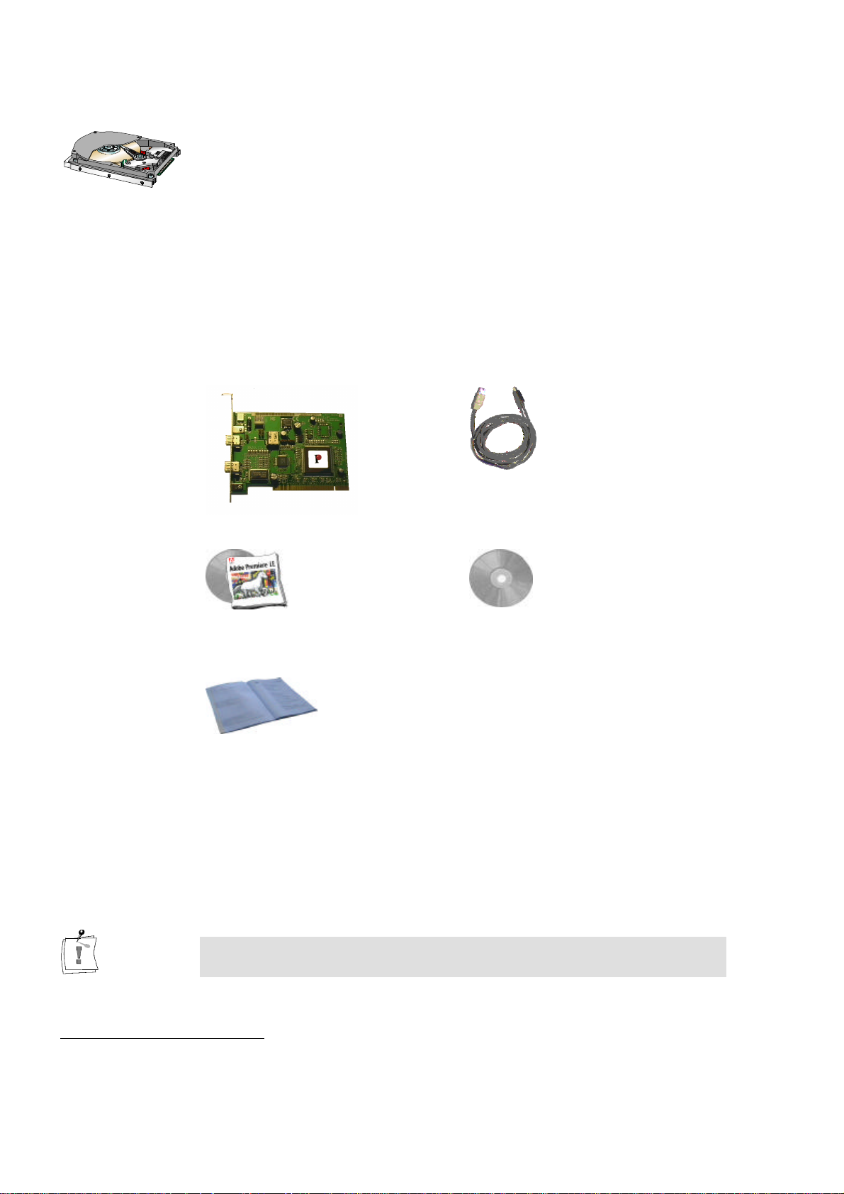
PACKAGE CONTENTS
Make sure your miroVIDEO DV200 kit is complete before you begin the
installation. The system includes*:
miroVIDEO DV200 board
Adobe Premiere and documentation
User´s Guide
**
***
IEEE-1394 DV cable
CD-ROM with driver software,
miroVIDEO DVTools, Presets and drivers
for Adobe Premiere
If any parts are missing, please contact your retailer.
Computer components are sensitive to electrostatic charge. Do not take the
miroVIDEO DV200 board out of its antistatic package until you install it.
*
The package contents may vary from the contents listed in this manual.
**
For an exact model name and serial number of your board, refer to the label on the board.
***
As soon as Adobe Premiere 5.1LE will be available, this version of Adobe will be included in the delivery scope
of miroVIDEO DV200.
4
Page 11

User´s Guide
The following chapter shall help the experienced user to start using the
miroVIDEO DV200 board immediately.
For more detailed installation instructions, please refer to the subsequent
chapters in the manual.
QUICK INSTALLATION
Install Adobe Premiere.
þ Place the Adobe Premiere-CD-ROM in your CD-ROM drive.
þ If the installation program is not started automatically, select Run…
from the Start menu.
þ Depending on your drive,
for Adobe Premiere 4.2LE enter, for example:
e:\english\win95&nt\disk1\setup,
for Adobe Premiere 5.1LE enter, for example:
e:\premiere\setup,
then click OK.
þ Follow the installation instructions on the screen.
Quick start
Install the miroVIDEO DV200 board.
þ Turn your computer and all peripherals off.
þ Remove the necessary cables.
þ Open the computer's housing.
þ Remove the slot cover.
þ Insert the board.
Reassemble the computer.
þ Reassemble the computer.
þ Reconnect all cables.
Install the miroVIDEO DV200 software.
þ Place the CD-ROM in the CD-ROM drive.
þ Follow the installation program instructions on the screen.
Connect the DV device to the DV200 board.
þ Connect the DV device to the DV200 board using the IEEE-1394
cable.
Connect a video monitor/television to the DV device.
þ Connect a video monitor or a TV set to the appropriate video output
of your DV device using the appropriate cable.
Establish the audio link.
þ Connect an audio cable to the audio output of your DV device.
þ Connect the other end of the audio cable to the audio input of your
video monitor/TV set.
5
Page 12

miroVIDEO DV 200
SCANNING DV (QUICK START)
Test your system.
Use the DVExpert from the miroVIDEO DV200 Program Group to test
the performance of your hard disk and your 1394 system.
Check preferences.
Start DVTools from the miroVIDEO DV200 program group. From the
Tools menu, select Preferences and check the settings.
Turn on DV device.
Turn on your DV device. Make sure that it is running in VTR mode.
Scan DV tape.
From the Tools menu, select Scan DV tape. Scan additional tapes, if
desired.
VIEWING CLIPS AND ADDING TRIMS (QUICK START)
Open a Tape Gallery.
Double-click a tape gallery name in the DV Explorer.
Preview the clips.
Double-click on a clip. In the Clip Info window click on the Eye button.
Choose the clips you want to capture.
Drag and drop the clips from the Tape Gallery into the Capture Gallery.
Add trims.
Define in and out points using the DV Device Controller.
Save the Capture Gallery file.
Save the Capture Gallery using the Save as menu item from the File
menu.
6
Page 13

User´s Guide
CAPTURING DV (QUICK START)
Open a Capture Gallery.
Open the Capture Gallery you want to capture.
Check the file size.
Check the file size in the status bar at the bottom of the Capture Gallery.
Capture AVI files.
Click on the Capture button on the right-hand side of the Capture
Gallery.
Enter the file name and the directory.
If you do not want to use the default drive which was determined in the
Preferences window, select a drive and directory where you want to
capture the file/s and enter a file name for the first clip.
EDITING AVI FILES USING ADOBE PREMIERE (QUICK START)
Start Adobe Premiere.
Click on the corresponding button on the right-hand side in the Capture
Gallery.
Select a Preset.
Select a suitable Preset from the Adobe Project Presets.
Import AVI file(s).
From the File menu, select Import and File.
Edit AVI file(s).
Add effects and edit your video.
Make a movie.
From the Make menu, select Make Movie (Adobe Premiere 4.2LE).
From the File menu, select Export (Adobe Premiere 5.1LE).
PRINTING TO DV (QUICK START)
Open the miroVIDEO DVTools.
Click Program Files in the Start menu. Select the program group
miroVIDEO DV200 and click on miroVIDEO DVTools.
Insert a new tape.
Insert a new tape and rewind it to a position where you want to start
recording.
7
Page 14

miroVIDEO DV 200
Select a file.
Click on the Print-to-tape button on the right-hand side of the Capture
Gallery. DVTools will prompt you to select the file you want to print to
tape. After selecting the file, the print-to-tape process will start
immediately.
CAPTURING SINGLE FRAMES (QUICK START)
Connect your DV equipment.
If you haven't already, connect your DV camcorder or DV video
recorder to the DV200 board.
Turn on your DV equipment.
Switch your DV device on. Select the desired mode (either VTR or
Camera mode).
Open the DV Device Controller.
To open the DV Device Controller, click on the (camera) icon in the
DVTools window.
Create bitmap.
Click on the (snapshot) button.
Name and save the BMP file.
Enter a name and a location where you like to save your BMP file.
What's next?
For more detailed instructions concerning any of the above functions, please
refer to the following chapters. You can also find information concerning the
installation of a PCI expansion board in the documentation supplied with
your computer.
8
Page 15

User´s Guide
Installing Adobe Premiere
The following chapter describes the procedure to install Adobe Premiere.
It is required that you install Adobe Premiere before installing the
miroVIDEO DV200 board and software. The DV200 software installation
program needs to know where the Adobe Premiere folders are located so
that it can copy the DV200 plug-ins and presets into the corresponding
folders.
Proceed as follows to install Adobe Premiere:
1. Place the Adobe Premiere CD-ROM in your CD-ROM drive.
2. If the installation program is not started automatically, select Run… from
the Start menu.
3. Depending on your drive, enter, for example:
• for Adobe Premiere 4.2LE
e:\english\win95&nt\disk1\setup.
• for Adobe Premiere 5.1LE
e:\premiere\setup.
Adobe Premiere
documentation
If your CD-ROM drive has a different drive designation, change the path
accordingly.
—or—
4. Click on Browse..., switch to your CD-ROM drive and to the directory
mentioned above and double-click the setup.exe file.
5. Click OK.
6. Follow the program installation instructions on the screen.
The complete Adobe Premiere documentation is available as PDF file on the
corresponding Adobe Premiere CD-ROM. You can view the documentation
using the Acrobat Reader. If the Acrobat Reader has not already been
installed on your computer, it will be installed together with your DV200
software.
After you have installed Adobe Premiere on your computer, you can install
the miroVIDEO DV200 board.
9
Page 16
miroVIDEO DV 200
Installation
This chapter explains how to install the DV200 board.
Computer components are sensitive to electrostatic charge. Do not take the
miroVIDEO DV200 board out of its antistatic package until you install it.
To install the board, you need a screwdriver.
To insert your DV200 board in your computer, proceed as follows:
1. Discharge electrostatic charge.
Discharge electrostatic charge by touching the metal case of your
computer.
2. Switch off the devices and pull the power cord.
Switch off the computer and all peripheral devices. Pull out the power
cord and disconnect all necessary cables.
3. Open the computer.
Loosen the screws of the computer's cover and remove the cover. Keep
the screws in a safe place.
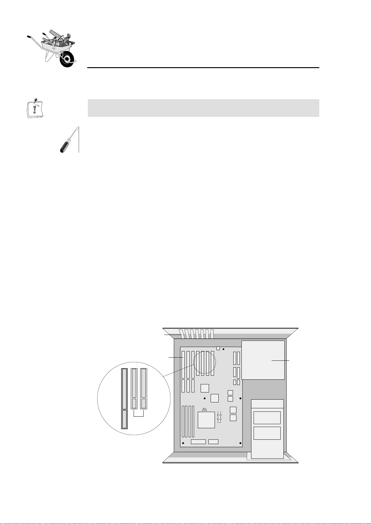
4. Select a slot.
Select a free PCI slot. PCI slots are the shorter ones available in your
computer and mostly made of white plastic. Make sure that the PCI slot
you use supports busmastering. If you are not sure about this, please
consult your computer documentation.
Slot shields
Slots
PCI slots
PCI slots
Power
supply
unit
10
Page 17
User´s Guide
5. Remove the slot shield.
Remove the screw and the slot shield for the PCI slot you have selected.
Keep the screw because you will need it later to secure the board once it
is installed.
6. Unpack the board.
Remove the DV200 from its sleeve.
You only need to connect the internal connector to your computer´s power
supply, if you plan to use devices such as video conferencing cameras that
require a 6-pin 1394 cable.
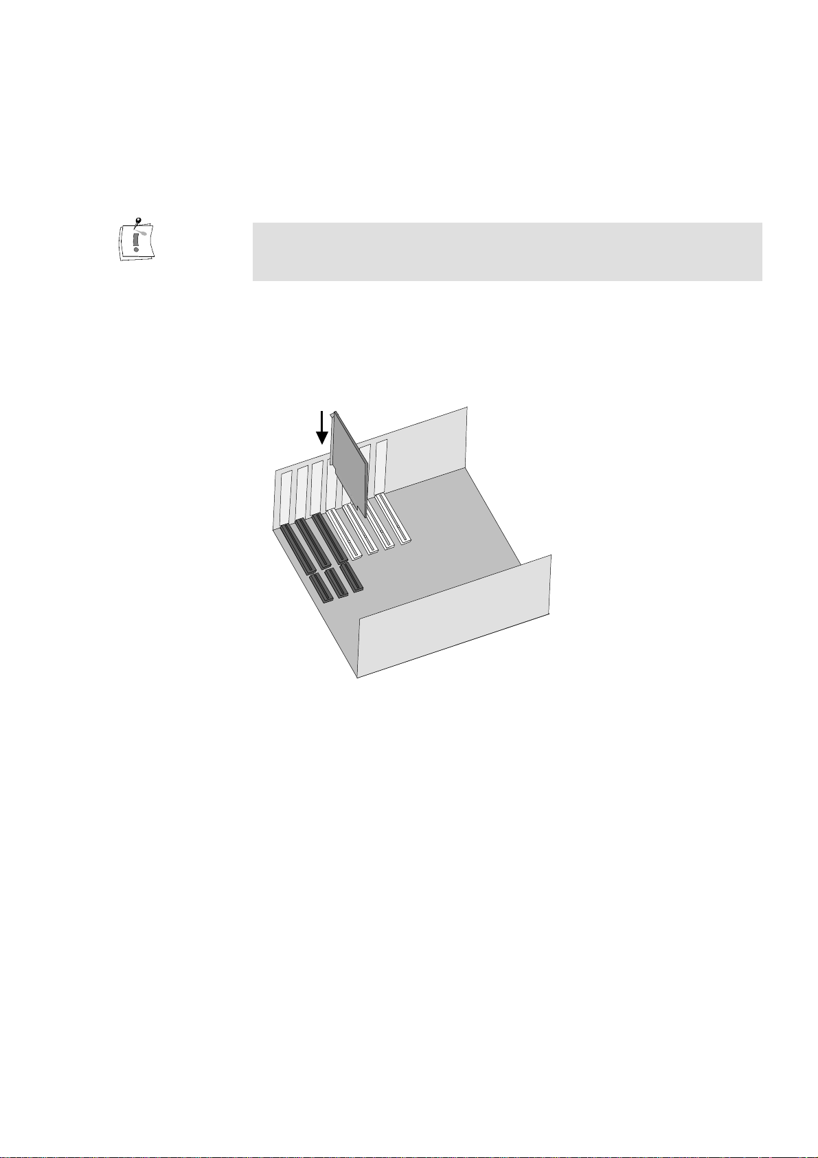
7. Insert the board.
Carefully insert the board into the PCI slot you selected by holding the
board at the top and gently pushing both ends into the slot. Press onto the
upper edge of the board to make sure it is firmly seated in the slot.
8. Fasten the bracket.
Fasten the board´s bracket at the back of the computer using the screw
you saved from the shield.
9. Reassemble the computer, reconnect the cables.
Reassemble the computer and replace the computer cover. Connect all
cables that have been disconnected before the installation.
Now that the hardware installation is complete, you can proceed with the
DV200 driver and software installation (see next chapter).
11
Page 18

miroVIDEO DV 200
Installing the software
Once you have installed the miroVIDEO DV200 into your computer, you
can install the miroVIDEO DV200 drivers and software. The installation
steps for the Windows 95 August Release, Windows 95 OSR2, Windows 98
and Windows NT are slightly different.
Windows 95
Windows 98
Before installing the miroVIDEO DV200 drivers for Windows 95, we
recommend you to identify the Windows version you use first.
You can check which Windows 95 version you use by entering the DOS
command ver. The Windows 95 OSR 2 (OEM Service Release 2) version
has the version number: Windows 95. [Version 4.00.1111] or [Version
4.00.950b]; the August Windows 95 Release has the version number:
Windows 95. [Version 4.00.950]. For detailed information on how to use the
DOS ver command refer to the appendix in the section “Identifying the
Windows 95 version” (page VI).
The complete installation consists of the following steps:
s Installing drivers for Windows 13
s Windows 95 (Release August 95) as of page 13, or
s Windows 95 (Release August 95) as of page 14.
s Installing the software for Windows 95 / Windows 98 as of page 16.
If you use Windows 98, please proceed with the “Installing drivers for
Windows 98” section on page 15.
The complete installation consists of the following steps:
s Installing drivers for Windows 98 as of page 15.
Windows NT
s Installing the software for Windows 95 / Windows 98 as of page 16.
If you use Windows NT, please read the “Installing software for
Windows NT 4.0” section as of page 19.
Among other things, installing the miroVIDEO DV200 software copies the
miroVIDEO DV200 drivers to your hard disk. The miroVIDEO DV200
program group is created, and—among other things—the expanded Adobe
Premiere project defaults (Presets) are copied to your hard disk.
12
Page 19
User´s Guide
INSTALLING DRIVERS FOR WINDOWS 95
Windows 95 (Release August 95)
Windows 95
(Release
August 95)
1. Switch computer on.
Switch your computer on. Windows 95 is started automatically.
If your computer is configured in such a way, that Windows 95 is not
started automatically, please start Windows 95 now.
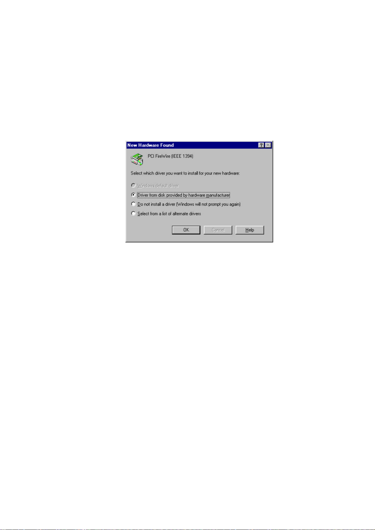
After Windows 95 starts, the New hardware found dialog box will appear.
A PCI FireWire (IEEE 1394) will be detected.
2. Select Driver from disk provided by hardware manufacturer,
click OK.
In the New hardware found dialog box, click the Driver from disk
provided by hardware manufacturer option. Click OK.
3. Insert CD-ROM.
Insert the installation CD-ROM into the CD-ROM drive.
4. Click Browse... .
Click on the Browse... button.
5. Switch to the \DRIVER directory, click OK.
Switch to your CD-ROM drive and go into the \DRIVER directory.
Select DV200.inf and click OK.
6. Click OK.
Click the OK button again.
After the drivers have been copied, the installation program starts
automatically. Proceed with the “ Installing the software for Windows 95 /
Windows 98” section as of page 16.
13
Page 20
miroVIDEO DV 200
Windows 95 (OSR 2)
Windows 95
(OSR 2)
To install the drivers for the OSR2 Release, proceed as follows:
1. Switch on computer.
Switch on your computer. Windows 95 is started automatically. If your
computer is configured in such a way, that Windows 95 is not started
automatically, please start Windows 95 now.
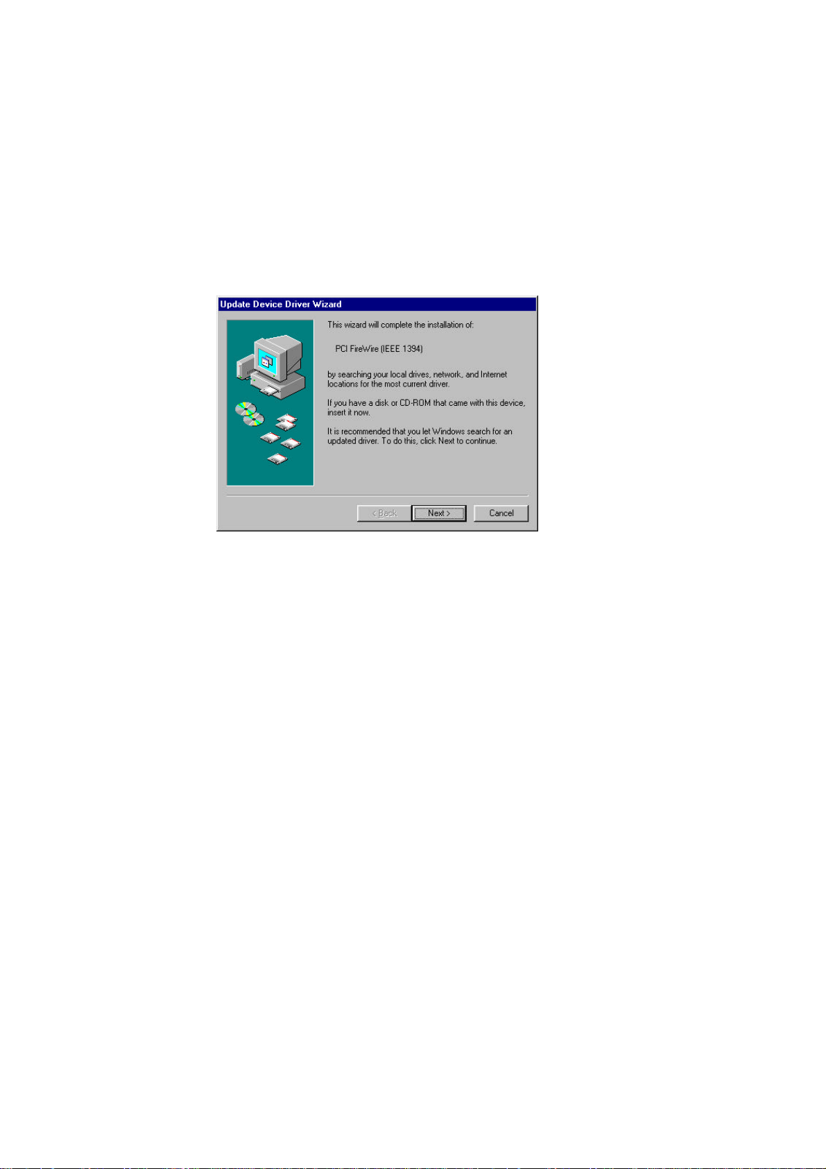
After Windows 95 starts, the New hardware component found dialog box
appears followed by the Update Device Driver Wizard dialog. A PCI
FireWire (IEEE 1394) will be detected.
2. Click Next.
Click on the Next button.
3. Insert the CD-ROM.
Insert the installation CD-ROM into the CD-ROM drive.
4. Click Other Locations....
Click on the Other Locations... button.
5. Click Browse... .
Click on the Browse... button.
6. Switch into the \DRIVER directory, click OK.
Switch to your CD-ROM drive and go into the \DRIVER directory. Click
OK.
7. Click Finish.
Click on the Finish button.
8. Click OK and Browse... again.
When your system requests you to insert the CD-ROM again, click on OK
and once again on Browse... .
9. Switch into the \DRIVER directory, click OK.
14
Switch to your CD-ROM drive and go into the \DRIVER directory. Click
OK.
10.Click OK.
Click the OK button again.
Page 21
User´s Guide
After the drivers have been copied, the installation program starts
automatically. Proceed with the “ Installing the software for Windows 95 /
Windows 98” section as of page 16.
INSTALLING THE DRIVERS FOR WINDOWS 98
Microsoft provides Windows 98 with own drivers for 1394 bus boards.
1. Switch on computer.
Switch on your computer. Windows 98 is started automatically.
If your computer is configured in such a way, that Windows 98 is not
started automatically, start Windows 98 now.
After Windows 98 starts, the new hardware is found, and the Add New
Hardware Wizzard dialog appears.
2. Click Next.
Click on the Next button.
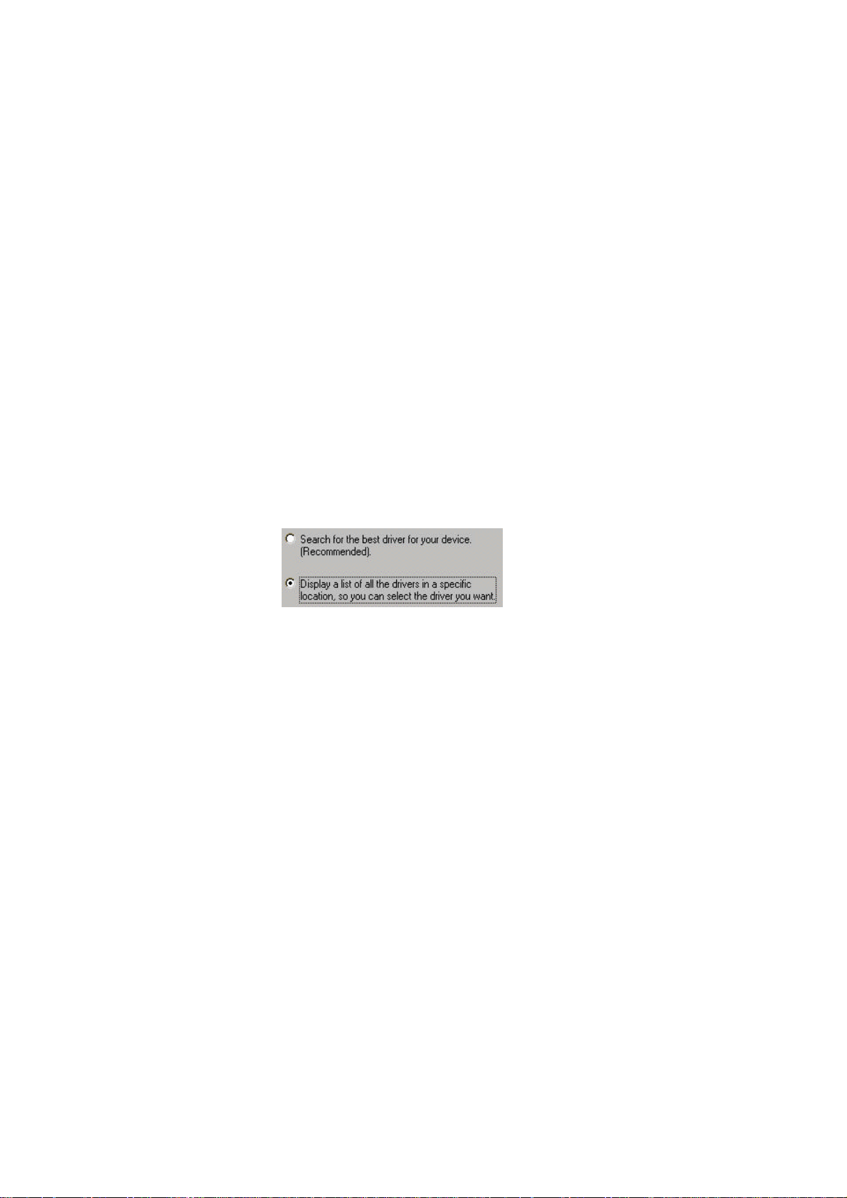
3. Select Display a list of all drivers in a specific location, click Next.
Select the option Display a list of all drivers in a specific location, so you
can select the driver you want and click on Next.
In the following window the found Adaptec drivers are displayed.
4. Insert the CD-ROM.
If you have not already done so, insert the installation CD-ROM into the
CD-ROM drive.
5. Click Have Disk... .
Click on the Have Disk... button.
6. Click Browse, switch to the :\DRIVER directory.
Click on the Browse button and switch to the directory :\DRIVER on
your CD-ROM drive.
7. Click OK.
Click on the OK button.
8. Click Next.
Click Next to complete the installation of the DV200 driver.
After the drivers have been copied, the installation program starts
automatically. Proceed with the “ Installing the software for Windows 95 /
Windows 98” section as of page 16.
15
Page 22
miroVIDEO DV 200
INSTALLING THE SOFTWARE FOR WINDOWS 95 / WINDOWS 98
After installing the driver, you can install the remaining miroVIDEO DV200
software (miroINSTANT Video, Adobe Presets etc.) using the installation
program.
The installation program is started automatically in the language specified via
the Regional Settings (Start Menu, Settings, Control Panel, Regional
Settings) of the installed Windows version.
If you use other regional settings than English, German or French, you will
have to select the language in which the installation should be carried out.
1. If necessary, change the language, click Next.
If necessary, select the language in which the installation should be carried
out.
If you have activated the German, English, or French Regional Settings
and nevertheless want to change the language of the installation program,
click the button Back first and then select the language.
Click on the Next button.
This installation step is not required, if you have activated the German,
English, or French Reginonal Settings.
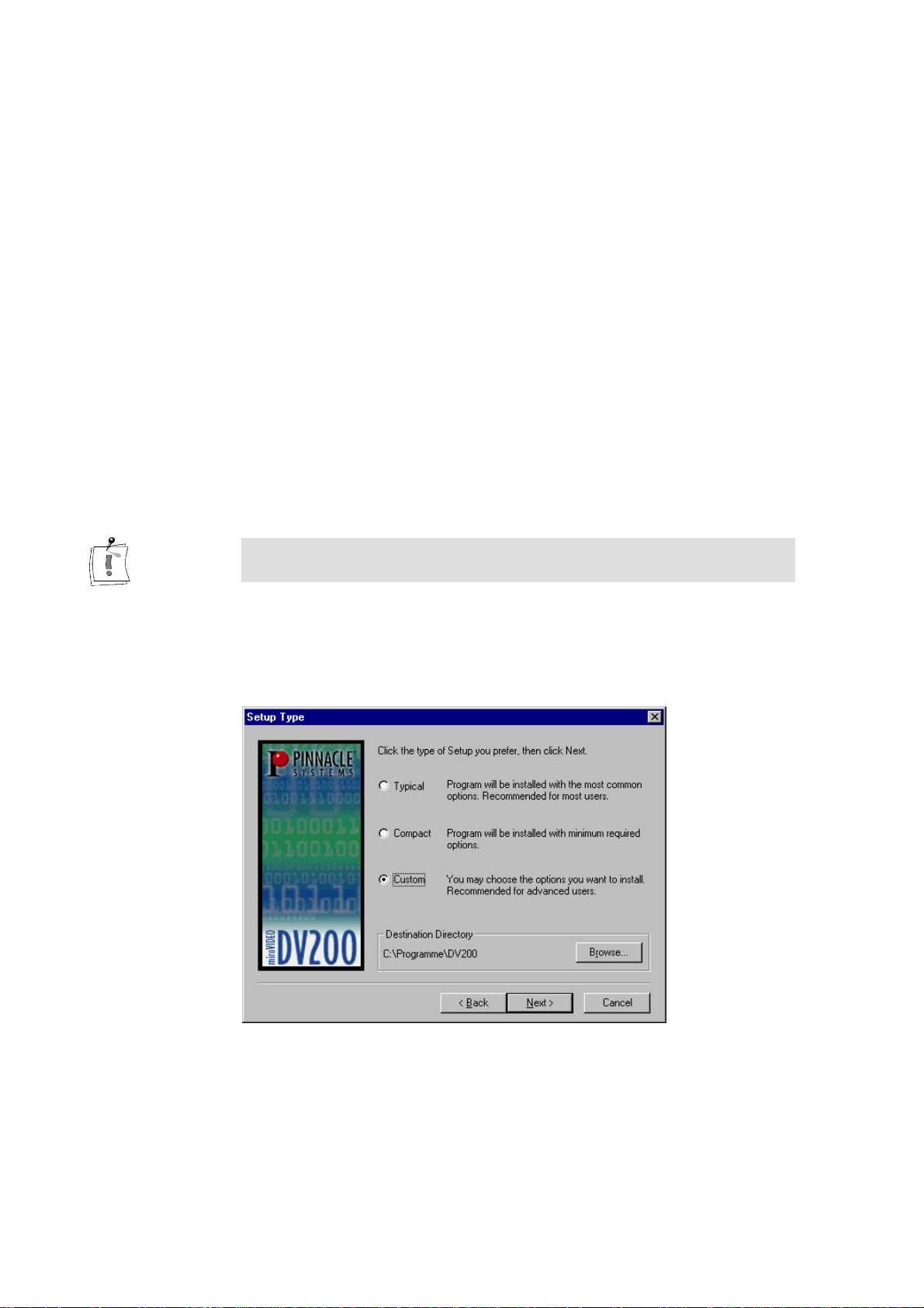
2. Select a setup type.
In the Setup Type window, select whether you prefer a typical, a compact,
or a user-defined installation.
16
s Typical: Installs all components and uses the default settings.
s Compact: Skips some components (e.g. online manual) and uses the
default settings. You should not choose this option.
s Custom: Lets you select the components and allows to adjust the
settings individually. You should only choose this option, if several
versions of Premiere are installed on your computer, if your system
hard disk is very slow.
Page 23
User´s Guide
3. If necessary, change the hard disk / directory.
If you wish to copy the files to another hard disk / another directory, click
on the Browse... button and define the hard disk / the directory. The driver
software should be installed on the system hard disk and not on the video
hard disk!
4. Click Next.
Click on Next to proceed with the installation.
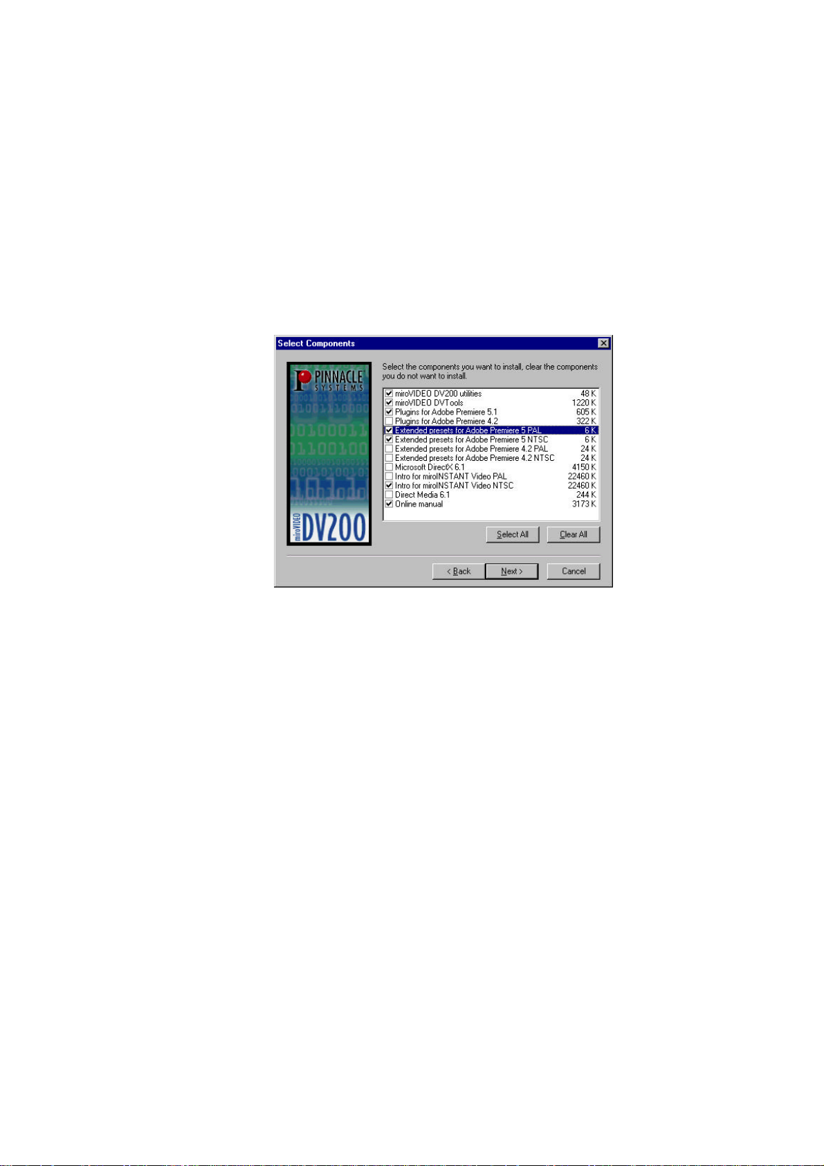
5. If necessary, select the components.
If you have chosen Custom as setup type, you can directly choose those
components in the dialog box Select Components, which you want to
install.
In the Select components dialog box, you can install the following
components:
s miroVIDEO DV200 utilities: tools and README file,
s miroVIDEO DVTools: video editing software,
s Plugins for Adobe Premiere 5.1: A set of Adobe Premiere 5.1 plug-ins
for playback, device control and capture, including miroINSTANT
Video 5.0,
s Plugins for Adobe Premiere 4.2: Adobe Premiere 4.2 plug-in,
miroINSTANT Video 2.0 allows saving valuable of computing time
when creating projects with Adobe Premiere,
s Extended Presets for Adobe Premiere 4.2 NTSC: Presets for Adobe
Premiere which have been developed especially for the DV200 board
and the NTSC standard.
s Extended Presets for Adobe Premiere 4.2 PAL: Presets for Adobe
Premiere which have been developed especially for the DV200 board
and the PAL standard.
s Extended Presets for Adobe Premiere 5.1 NTSC: Presets for Adobe
Premiere which have been developed especially for the DV200 board
and the NTSC standard.
s Extended Presets for Adobe Premiere 5.1LE PAL: Presets for Adobe
Premiere which have been developed especially for the DV200 board
and the PAL standard.
17
Page 24

miroVIDEO DV 200
s Intro for miroINSTANT Video PAL: PAL-compatible intro files for
your AVI movies, the intro movies help you switch on the VCR just in
time when recording video,
s Intro for miroINSTANT Video NTSC: NTSC-compatible intro files for
your AVI movies, the intro movies help you switch on the VCR just in
time when recording video,
s Microsoft Direct Media 6.x: Windows 95/98 extension (we
recommend to leave this item selected).
s Online manual: This manual in PDF format and the Acrobat Reader, if
it is not already installed on your system.
After having determined the components, click Next.
This installation step is not required, if you have chosen Typical or
Compact as setup type.
6. Select the video standard you use and click on Next.
If you are not sure which video standard you use, please refer to the
Appendix on page VII.
7. Select the directory to which you want to copy the Adobe Premiere
Plug-Ins and click Next.
By default, the Adobe Premiere Plug-Ins are located in the
\WINAPP32\PREMIERE\PLUG-INS (Adobe Premiere 4.2LE) or
\PLUG-INS (Adobe Premiere 5.1LE) folder. If this is not the case, select
your Premiere plug-ins folder.
8. Select the directory for the intros, click Next.
Select the directory into which you want to have the intros copied and
click on the Next button.
9. Choose Program Group, click Next.
Choose the Program Group where you want the DV200 software to be
located (default: miroVIDEO DV200). Click on Next.
In the Start copying files window, all components you have chosen will be
listed.
10.Click Next to start copying.
Now the selected components will be installed.
11.Click Finish.
If Windows requests you to restart the computer, click Finish.
18
After you installed the DV200 hardware and software, you can connect
the devices you use with the board.
Page 25

User´s Guide
INSTALLING SOFTWARE FOR WINDOWS NT 4.0
1. Switch on the computer.
If you have not done so already, switch on the computer.
2. Insert CD-ROM.
If you have not done so already, insert the installation CD in your CDROM drive.
Under Windows NT the installation program should start automatically. If this
is not the case, the AutoStart function of your CD-ROM drive has probably
been disabled. In this case, you have to start the installation program manually.
To do so, elect the Run... command in the Start menu and enter [your drive
letter]:\APP\SETUP.EXE. Click on OK to start the installation program.
The installation program is started automatically in the language specified via
the Regional Settings (Start Menu, Settings, Control Panel, Regional
Settings) of the installed Windows version.
If you use other regional settings than English, German or French, you will
have to select the language in which the installation should be carried out.
3. If necessary, change the language, click Next.
If necessary, select the language in which the installation should be carried
out.
If you have activated the German, English, or French Regional Settings
and nevertheless want to change the language of the installation program,
click the button Back first and then select the language.
Click on the Next button.
This installation step is not required, if you have activated the German,
English, or French Reginonal Settings.
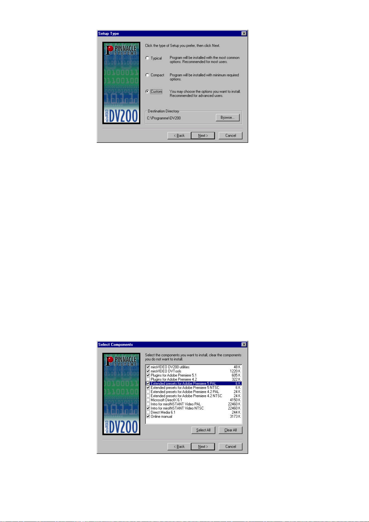
4. Select a setup type.
In the Setup Type window, select whether you prefer a typical, a compact,
or a user-defined installation.
19
Page 26
miroVIDEO DV 200
s Typical: Installs all components and uses the default settings.
s Compact: Skips some components (e.g. online manual) and uses the
default settings. You should not choose this option.
s Custom: Lets you select the components and allows to adjust the
settings individually. You should only choose this option, if several
versions of Premiere are installed on your computer, if your system
hard disk is very slow.
5. If necessary, change the hard disk / directory.
If you wish to copy the files to another hard disk / another directory, click
on the Browse... button and define the hard disk / the directory. The driver
software should be installed on the system hard disk and not on the video
hard disk!
6. Click Next.
Click on Next to proceed with the installation.
7. If necessary, select the components.
If you have chosen Custom as setup type, you can directly choose those
components in the dialog box Select Components, which you want to
install.
20
Page 27
User´s Guide
In the Select components dialog box, you can install the following
components:
s miroVIDEO DV200 utilities: tools and README file,
s miroVIDEO DVTools: video editing software,
s Plugins for Adobe Premiere 5.1: A set of Adobe Premiere 5.1 plug-ins
for playback, device control and capture, including miroINSTANT
Video 5.0,
s Plugins for Adobe Premiere 4.2: Adobe Premiere 4.2 plug-in,
miroINSTANT Video 2.0 allows saving valuable of computing time
when creating projects with Adobe Premiere,
s Extended Presets for Adobe Premiere 4.2 NTSC: Presets for Adobe
Premiere which have been developed especially for the DV200 board
and the NTSC standard.
s Extended Presets for Adobe Premiere 4.2PAL: Presets for Adobe
Premiere which have been developed especially for the DV200 board
and the PAL standard.
s Extended Presets for Adobe Premiere 5.1 NTSC: Presets for Adobe
Premiere which have been developed especially for the DV200 board
and the NTSC standard.
s Extended Presets for Adobe Premiere 5.1PAL: Presets for Adobe
Premiere which have been developed especially for the DV200 board
and the PAL standard.
s Intro for miroINSTANT Video PAL: PAL-compatible intro files for
your AVI movies, the intro movies help you switch on the VCR just in
time when recording video,
s Intro for miroINSTANT Video NTSC: NTSC-compatible intro files for
your AVI movies, the intro movies help you switch on the VCR just in
time when recording video,
s Microsoft Direct Media 6.x: Windows 95/98 extension (we
recommend to leave this item selected).
s Online manual: This manual in PDF format and the Acrobat Reader, if
it is not already installed on your system.
After having determined the components, click Next.
This installation step is not required, if you have chosen Typical or Compact
as setup type.
8. Select the video standard you use and click on Next.
If you are not sure which video standard you use, please refer to the
Appendix on page VII.
9. Select the directory to which you want to copy the Adobe Premiere
Plug-Ins and click Next.
By default, the Adobe Premiere Plug-Ins are located in the
\WINAPP32\PREMIERE\PLUG-INS (Adobe Premiere 4.2LE) or
\PLUG-INS (Adobe Premiere 5.1LE) folder. If this is not the case, select
your Premiere plug-ins folder.
21
Page 28

miroVIDEO DV 200
10.Select the directory for the intros, click Next.
Select the directory into which you want to have the intros copied and
click on the Next button.
11.Choose Program Group, click Next.
Choose the Program Group where you want the DV200 software to be
located (default: miroVIDEO DV200). Click on Next.
In the Start copying files window, all components you have chosen will be
listed.
12.Click Next to start copying.
Now the selected components will be installed.
13.Click Finish.
If Windows requests you to restart the computer, click Finish.
After you installed the DV200 hardware and software, you can connect
the devices you use with the board.
22
Page 29

User´s Guide
INSTALLING THE DV200 SOFTWARE LATER
In case you want to install the DV200 software or individual components for
Windows 95 oder Windows NT later, proceed as follows:
1. In the Start menu, select the Run... command.
2. Insert the CD-ROM from the DV200 package contents in your CDROM.
3. Enter [Your CD-ROM drive letter]:\APP\SETUP.EXE.
Click OK.
4. Proceed as described on page 19 as of step 2.
UNINSTALLING THE DV200 SOFTWARE AND DRIVERS
For information on how to uninstall the miroVIDEO DV200 and DVTools,
refer to the ”Uninstalling miroVIDEO DV200 drivers and DVTools” chapter
in the Appendix on page VI.
23
Page 30
miroVIDEO DV 200
Connecting the devices
You can connect any DV video device (camcorder or VCR) with an IEEE1394/DV connector to the DV200. You will find a list of compatible devices
in the Appendix on page VII and in the readme file.
You will find more detailed hardware connection diagrams in the Appendix
as of page I.
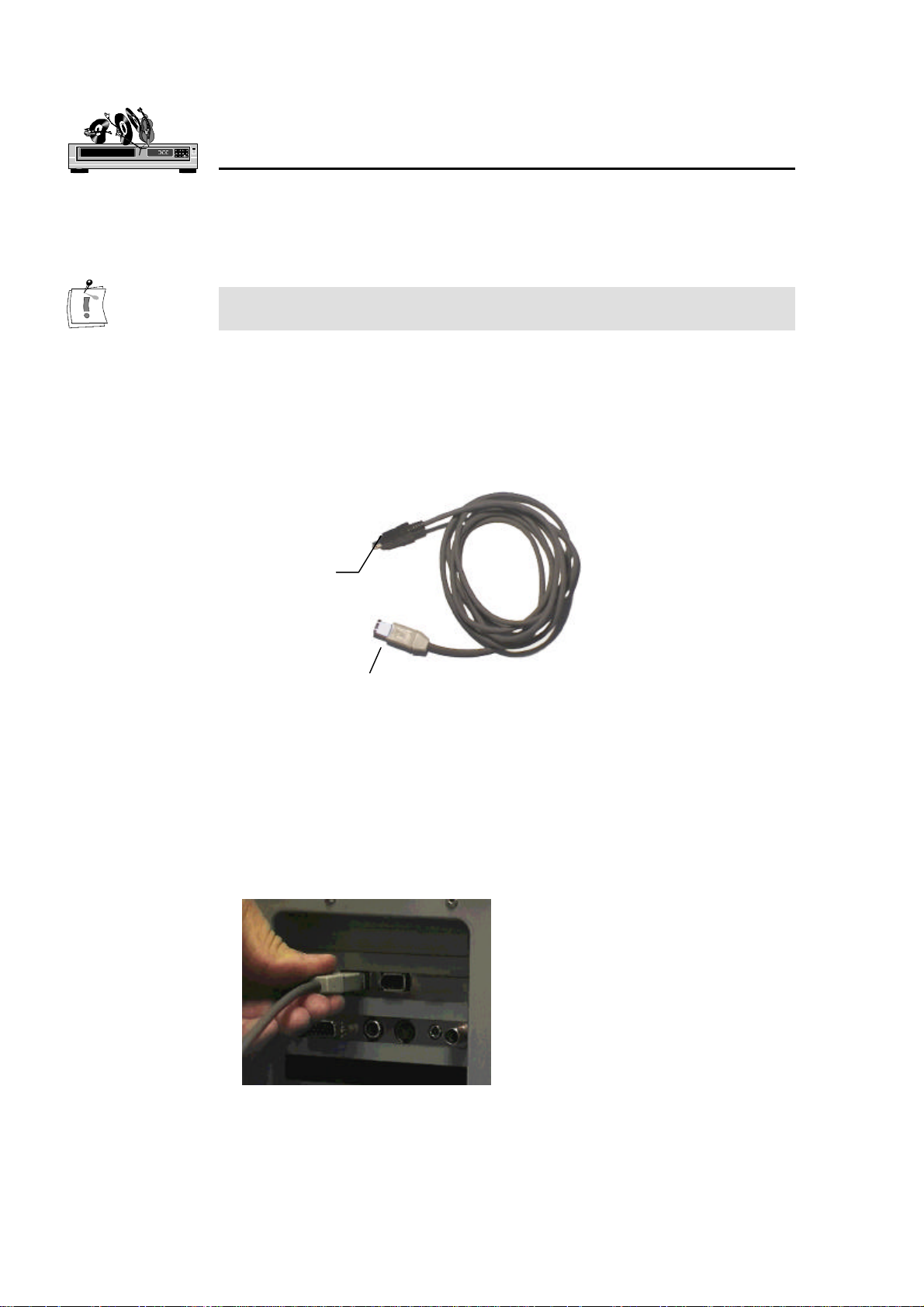
ATTACHING A DV CAMCORDER OR A DV VCR
To connect your DV camcorder/VCR to the miroVIDEO DV200 board, use
the IEEE-1394 DV cable included in the package.
Connects to the
DV camcorder/
VCR
Connects to the
miroVIDEO DV200
board
IEEE-1394 DV cable
To connect your DV camcorder/VCR to the miroVIDEO DV200 board,
proceed as follows:
1. Connect the IEEE-1394 cable to the DV200 board.
Connect the 6-pin connector of the IEEE-1394 DV cable to one of the
two external 1394 data ports of your miroVIDEO DV200 board. You can
use either data port.
24
Page 31

User´s Guide
2. Connect the IEEE-1394 cable to the DV device.
Connect the either of the 6-pin connectors of the IEEE-1394 DV cable to
the DV IN/OUT or the DV OUT connector of your DV camcorder/VCR.
CONNECTING THE TV SET/VIDEO MONITOR
To view the recorded footage, a TV set or a video monitor must be attached
to the DV camcorder/VCR. (Some camcorders have an integrated display, in
which case you do not need to attach a video monitor.) In case you do not
want to connect a TV set or video monitor to your board, you can always
use the Preview window provided with the miroVIDEO DVTools.
Video connections
To attach a TV set/video monitor to your DV camcorder/VCR, you need a
S-Video or composite video cable.
To connect a TV set/video monitor to your camcorder/VCR:
• For S-Video monitors,
connect one end of the S-Video cable to the S-Video output of your
camcorder/VCR and the other end to the S-Video input of your video
monitor.
• For Composite video monitors,
connect one end of the composite cable to the composite output of your
camcorder/VCR and the other end to the composite video input of your
video monitor.
25
Page 32

miroVIDEO DV 200
Audio connections
For the audio connections you need one audio cable for each channel.
To connect the audio cables, proceed as follows:
1. Connect the audio cables to the DV device.
Connect one end of the audio cables to the audio outputs of your
camcorder/VCR (AUDIO OUT).
2. Connect the audio cables to your monitor.
Connect the other end to the audio inputs of your video monitor or your
TV set.
26
This audio connection is only required to make the sound audible, the
transfer of the audio data to the computer is done via the IEEE-1394
connection.
Page 33

User´s Guide
Working with DV material
This chapter explains how to capture a single frame from your DV tape and
introduces the step-by-step process of capturing DV clips from tape using
DVTools, editing DV using Adobe Premiere, and printing DV back to tape.
The combination of the miroVIDEO DVTools and Adobe Premiere lets you
get the most out of your DV footage.
Preparations
Before you start working with DV material it is advisable to check your
system performance using the DVExpert. The DVExpert is located in the
miroVIDEO DV200 Program Group. In order to provide you with realistic
results, the disk being tested should be defragmented. If you use more than
one hard disk in your system, you should test them all and use the hard disk
with the fastest data rate.
For more information on the DVExpert, please click on the help button in the
DVTools.
Note that the DVTools require at least a 16-bit color resolution and an 800 x
600 resolution. If your display is set to fewer colors, an error message will
appear after starting the DVTools. On information about how to change the
color settings, please refer to the “Changing the number of colors and the
resolution” section in the Appendix on page VII.
MAKING MOVIES
In planning and capturing your movie, use the miroVIDEO DVTools.
DVTools allows you to scan the DV tape, store clip locations, view the
individual clips, re-define and edit clip in points and out points (i.e., start and
end markers) and re-order clips. Once you have completed these steps, you
can create separate AVI files for each clip. After these AVIs have been
created you can use Adobe Premiere to add titles, transitions and special
effects. You can then output the final DV back to DV tape or—if you own a
miroVIDEO DC30 (plus) board— to conventional analog tape.
The difference between scanning and capturing
Scanning the tape does not capture the video and save it to the hard drive.
Scanning merely identifies all the clips on the tape so you can see which clips
are candidates for your final video, and which aren’t useful at all.
Capturing, on the other hand, saves the digital video on the hard drive. At
that point, with the digital video on your computer’s hard drive, you can edit
the clip using Adobe Premiere.
Neither scanning or capturing modifies your original videotape in any way.
Your original shots remain in their original form and quality.
27
Page 34

miroVIDEO DV 200
Some remarks on shooting DV footage
When shooting DV, you can use as many DV tapes as you like. DVTools is
capable of keeping track of as many DV tapes as you wish to scan. When
you scan the video tape later, the software will automatically detect the start
of a clip at each place where you started the recorder. Conversely, those
places where you stopped recording will automatically be detected as ends of
clips.
When shooting video footage, make sure the camcorder is running in
Camera mode.
Checking preferences in miroVIDEO DVTools
Before using the miroVIDEO DVTools to capture your video footage, it is
advisable to check the preferences with regard to your television standard
and some recording parameters. In Western Europe (except for France), the
PAL standard is used; the standard used in the USA is NTSC. For details on
television standards, see the p. VII in the Appendix.
To check the preferences in the miroVIDEO DVTools, proceed as follows:
1. Launch the miroVIDEO DVTools.
Click Program Files in the Start menu. Select the program group
miroVIDEO DV200 and click on miroVIDEO DVTools.
The Capture Gallery appears.
28
Page 35

User´s Guide
3. Checking the TV standard.
In the Capture Gallery, select the Tools menu and the Preferences menu
item. This dialog will be displayed the first time you launch DVTools. The
program can automatically detect the video standard if the DV device is
connected to the card and is switched on. You must not overwrite this
setting.
3. Choose your preferred capture method
You can select between a single pass capture and a multi pass capture.
Default is single pass capture since your PC system should be fast enough
to capture DV footage in one pass. If you find too many dropped frames
on the capture you might select the multi pass capture method.
4. Select the capture drive.
Under Trim point based capture, select the hard drive and the directory
where you want to save the video. Please verify that enough storage space
is available on this drive.
5. Select the audio channel.
DV devices support two audio channels on a 32kHz setting. Select the
channel from which you want to capture the sound.
6. Select an appropriate value for the Length of blank. Click OK.
When scanning a DV tape containing long blank sections where no DV
footage has been recorded, the DVTools might abort the scanning process
in the middle of such a pause because it assumes that the blank section is
the end of the recording. To ensure that the DVTools continue to scan the
tape, you can enter a value (in seconds) under Length of blank. This value
determines the maximum length of a blank section which the DVTools
will accept as a pause but not as the end of a recording.
29
Page 36

miroVIDEO DV 200
Scanning a DV tape for clips
Once you have set the preferences, you can use miroVIDEO DVTools to
scan your DV tape(s) for clips. A clip is defined as a video sequence located
between an in point (start of take) and an out point (end of take).
To scan a DV tape for clips, proceed as follows:
1. Connect DV equipment.
If you haven't already, connect your DV camcorder or DV video recorder
to the miroVIDEO DV200 board. For instructions, see the chapter
„Connecting the devices“ on page 24 and the Appendix on page I.
2. Turn on your DV equipment.
Turn on your DV camcorder or DV video recorder. Make sure that your
DV camcorder is running in VTR mode.
3. Insert DV tape.
If you haven't already, insert the DV tape in your DV equipment.
4. Scan DV tape.
You can start the scanning process in three ways:
s Click the Tape Scan button in the right section of the Capture Gallery
(see icon).
s Right-click into the DV Explorer (mainly white area in the left section
of the Capture Gallery) and select Scan DV tape...
s From the Tools menu, select Scan DV tape.
It is also possible to scan the tape manually (Live capture) and capture the
video simultaneously. For information on the Live Capture, refer to page
53.
The DV tape is then rewound to the beginning and the DVTools display a
dialog box showing the progress of the scanning process. To abort this
process, click on Cancel.
5. Enter a name and description for the DV tape or rescan the tape.
After the tape has been rewound, DVTools will identify the tape.
s If the tape is unknown to the tape database, the program will prompt
you to enter a name and a description for the tape. After you have
typed in the information, the tape description will be stored in the
database.
s If the tape is already known, the program will allow you to abort the
tape scan or to rescan the tape. The clips from the previous scan are
remembered and you will be promoted as to where to start the new
scan. This is helpful if you have recorded new footage to a tape you
have previously scanned. You can scan in the new scenes, updating the
existing scan gallery, without having to re-scan the entire tape.
30
Next, DVTools scans the DV tape for clips. The scan process takes as
much time as it would take to play back the video footage on your tape.
For example, a 30-minute tape will take approximately 30 minutes to be
scanned if the tape is completely filled with video information. If the tape
Page 37

User´s Guide
only contains 15 minutes of video data the scan will need approx. 15
minutes.
Once the software has finished scanning the tape, a window appears in
which all the clips found on the video tape are depicted as „poster frames“
(the first frame in a clip). This Tape Gallery will be brought up any time
after you scanned a tape.
6. Scan additional DV tapes if necessary.
If you want to use several video tapes for your movie, have DVTools scan
for clips as described above.
Viewing clips and adding trims
To view your DV at full-screen size, a television set or video monitor must
be connected to your DV camcorder or DV video recorder (see p. 24). There
is also a preview window in the DV Device Controller that plays back your
DV in a small thumbnail window with a reduced resolution.
To view clips, proceed as follows:
1. Open DV tape (if necessary).
If the Tape Gallery with the clips of your video tape is not displayed
already, double-click a database name in the DV Explorer. The tape in
question must be in the DV camcorder.
A Tape Gallery then appears in which all the clips on your video tape are
depicted by the first frame (poster frame) of each clip.
3. Playing back clips.
To view a clip, first double-click on the desired clip. The Clip Info
window will then appear.
31
Page 38

miroVIDEO DV 200
The Clip Info window displays the title, the time code, and the trim points
(if there are any). If you wish to do so, you can enter a description for
your clip.
To rewind or forward the tape to the position where the clip is located,
click on the (eye) button. The DV device will take a while to find the
start of the clip.
32
The DV Device Controller will appear. You will know that the tape is
positioned to the start of the clip when the time code displayed at the top
of the window is identical with the clip start displayed at the bottom of the
window.
Page 39

User´s Guide
The DV Device Controller lets you control your DV device. The video
tape does not automatically stop when it reaches the end of a clip. To
pause the playback, click on the Pause button. For a detailed description
of the DV Device Controller, see p. 45.
3. Choose the clips you want to capture.
Once you have „sifted through“ your video footage, you can choose the
clips you actually want to capture. To do so, drag the desired clips from
the Tape Gallery and drop them in the Capture Gallery*. You can arrange
the clips in the Capture Gallery in any order.
4. Add trims.
Sometimes you may not want to use an entire clip, but rather only part of
a clip. In that case, you can edit the clip in question using the DV Device
Controller.
You can define the in point and out point of a clip using the (in point)
and (out point) buttons. You can either click on the buttons during
playback, or pause the tape at the desired location and then click on these
buttons. You can also forward and rewind the tape using the slider control
*
Drag & Drop:
Left-click the desired element. Hold the mouse button down and drag the element to the desired position. To
„drop“ the element, release the mouse button.
33
Page 40

miroVIDEO DV 200
at the bottom of the DV Device Controller window (jog-shuttle function).
Once you have finished inserting the points in the clip, click
(Apply) to save the trim points.
The original trim points are still stored in the clip database and can be
restored at any time by clicking on .
6. Save the Capture Gallery file.
Save the Capture Gallery file with the added clips and edits. To do so,
select the Save as... option in the File menu. These files are saved with the
extension *.sto.
Capturing DV (generating AVI files)
Now that you have selected the clips for your movie, you can generate AVI
files.
To generate AVI files from the clips, proceed as follows:
1. Open the Capture Gallery.
If you have not done so already, open the Capture Gallery you want to
capture. To do so, click on the File menu in the DVTools and select Open
Capture Gallery. Here you can select the Capture Gallery (*.sto file).
2. Check file size.
The status bar at the bottom of the Capture Gallery shows the clip count,
the total duration, and the total size of the AVI files that will be generated.
If you like to verify that you have enough disk space for capturing the
clips from this Gallery, click on your drive in Windows 95 Explorer. The
free space on your hard disk will be displayed. However, DVTools will
check if there is enough disk space available before capturing.
34
Page 41

User´s Guide
3. Capture AVI files.
To create AVI files from the clips in your Capture Gallery, click the
Capture button located on the right-hand side of the Capture Gallery.
4. Enter file name and directory.
If you do not want to use the default drive you chose in the Preferences
dialog, enter a file name and choose a directory to which you want to
copy the AVI files. All clips located in the Capture Gallery will then be
captured. The AVI files will be numbered according to the order of
capturing.
DVTools use a unique technology, in multi-pass capture mode, allowing
lossless capture also on slower computer systems. For that reason, DVTools
may search the DV tape one or more times to retrieve dropped frames.
Editing AVI files using Adobe Premiere
The DVTools allow you to directly launch Adobe Premiere without having
to do this from the Windows Start menu.
If you want to output your AVI file to the miroVIDEO DC30 board, you
must select the Optimized display for miroVIDEO DC30 option in the DV
Configuration tool.
For more information on this tool, please refer to page 50.
To edit your AVI file(s) using Adobe Premiere, proceed as follows:
1. Start Adobe Premiere.
To start Adobe Premiere, click on the corresponding button on the righthand side in the Capture Gallery. (If Adobe Premiere is not installed on
your system, this button will be disabled.)
2. Select a Project Preset.
Select an appropriate Project Preset, depending on whether you are using
PAL or NTSC and on whether you want to output your final DV file to a
DV tape or to an analog video tape via miroVIDEO DC30.
For more information on the Project Presets, refer to page 53.
3. Import AVI file(s).
To import one or more AVI files, go to the File menu and select the menu
commands Import and File... . Select the AVI file(s).
4. Edit AVI file(s).
At this point you can add effects and process your video. If necessary,
select the display mode for all frames of the video clips under Windows,
Construction window options, Track format.
5. Select output options.
In Adobe Premiere, select Make, Output Options. Under Type, select
Full Size Frame.
35
Page 42

miroVIDEO DV 200
6. Make a movie.
To make a movie, select the menu command Export Movie in the
File/Export menu. Specify the proper compression (predefined in the
Project Preset).
Instead of using the Export Moviee command and print the DV to tape using
the DVTools, you can also use the miroINSTANT Video tool to create your
final movie and to save it back to the DV tape. For more information on
miroINSTANT Video, please refer to the “miroVIDEO DC200 & Adobe
Premiere 4.2LE” chapter as of page 53 or the “miroVIDEO DC200 &
Adobe Premiere 5.1LE” chapter as of page 61.
Printing to DV
After you have generated an Adobe Premiere movie file, DVTools let you
print your files to tape.
To print video to tape, proceed as follows:
1. Check DV devices.
Make sure that your DV camcorder or DV recorder (PAL requires a
recorder) is connected to your DV200 board and that is switched on and
set to the VTR mode.
2. Close all open applications.
Before you start recording the clip back to tape, please close all other
programs currently running.
During the print-to-tape process, no other applications except for the
DVTools should be running.
3. Insert a new tape.
If you have not done so already, insert a new tape into your DV device
and rewind it to a position where you want to start recording.
4. Select a file.
To start printing your edited Adobe Premiere file back to DV tape, click
on the corresponding button on the right-hand side of the Capture
Gallery. DVTools will prompt you to select the file you want to print to
tape. You will be notified that any contents on your DV tape will be
overwritten. The DV Device Controller will start recording.
36
Page 43

User´s Guide
CAPTURING SINGLE FRAMES (SNAPSHOTS)
The miroVIDEO DVTools allow you to capture still images with the DV
recorder, the camcorder in VTR mode or directly from its lens.
Checking preferences in miroVIDEO DVTools
Before using the miroVIDEO DVTools to capture single frames from your
video footage, it is advisable to check the preferences with regard to your
television standard and the frame size.
To check the preferences in the miroVIDEO DVTools, proceed as follows:
1. Open the miroVIDEO DVTools.
Click Program Files in the Start menu. Select the program group
miroVIDEO DV200 and click on miroVIDEO DVTools.
2. Checking the TV standard.
In the Capture Gallery, select the Tools menu item...
... and the Preferences menu item.
37
Page 44

miroVIDEO DV 200
The DV data format will be autodetected at any time while DVTools is
running. You must not overwrite the setting.
4. Select an image size for your BMP file.
From the Snapshot list box select the size you want your frame to have.
The table below states the BMP resolutions that will result from the
different settings.
Setting NTSC PAL
Full size 720 x 480 (full TV size) 720x576
Quarter size 360x240 360x288
1/16 size 180x120 180x144
If you want to de-interlace your bitmaps, select the De-interlace option.
Click on OK. (For more information on the De-interlace feature, read the
„De-interlace“ section at the end of this chapter).
Capturing single frames
Once you have set the preferences, you can use the DVTools device
controller to capture a single frame from either recorded video footage or
directly from the lens.
To capture a single frame, proceed as follows:
1. Connect DV equipment.
If you haven't already, connect your DV camcorder or DV video recorder
to the miroVIDEO DV200 board. For instructions, see the chapter
„Connecting the devices“ on p.24 and the Appendix as of page I.
2. Turn on your DV equipment.
Turn on your DV camcorder or DV video recorder. If you want to
capture a single frame from your recorded video footage, make sure that
your DV camcorder is running in VTR mode and that a suitable tape has
been inserted.
If you wish to capture a single frame directly from the lens, set your
camcorder to the Camera mode and point it at the object you wish to
capture.
3. Open the DV Device Controller.
To open the DV Device Controller, click on the (camera) icon in the
DVTools window.
4. Create bitmap.
If you are running in the VTR mode, search out the frame you would like
to capture using the transport controls and click on the Pause button to
stop the tape.
38
Click on the (snapshot) button to temporarily store the image to
RAM.
Page 45

User´s Guide
5. Name and save the BMP file.
You can now enter a name and a location where you like to save your
BMP file.
De-interlacing
The DV200 software automatically de-interlaces the images you capture
from your DV tape. TV systems, such as NTSC and PAL use the interlacing
technique.
TV images are not scanned (drawn) line by line, but first all odd lines (1, 3, 5
etc.) are drawn and in a second step all even lines (2, 4, 6 etc.) are drawn.
The sections consisting of either odd or even lines are called fields.
When watching TV the human eye cannot distinguish the odd and the even
lines but merges them so that they appear as one. When capturing a DV
image, however, the resulting image would normally look distorted because
the odd and the even frames are put together.
The DV200 software, however, compensates for this with the feature called
de-interlacing by eliminating one field and generating a new enhanced image
from the remaining field.
39
Page 46

miroVIDEO DV 200
This chapter describes miroVIDEO DVTools in detail.
miroDVTools let you scan for clips on your DV tape, add in and out points,
control your DV devices, transfer DV to your hard disk and back to DV
tape.
miroVIDEO DVTools consists of three main components: the Capture
Gallery, the Tape Gallery, and the DV Device Controller.
CAPTURE GALLERY
The most important workspace in the miroVIDEO DVTools is the Capture Gallery. Here you can arrange the clips you want to capture, check the
running time and file size of a movie, generate AVI files, open Adobe
Premiere, and print AVI files back to tape.
To access the Capture Gallery,
miroVIDEO DVTools
• select Program Files from the Start menu. Select the miroVIDEO DV200
program group and click miroVIDEO DVTools.
The Capture Gallery opens.
The Capture Gallery consists of the menu bar, the tool bar, DV Explorer,
the film strip, the DV buttons and the status bar. The following sections
explain these individual components.
40
Page 47

User´s Guide
Menu bar
File menu
View menu
New Capture Gallery:
Lets you create a new Capture Gallery database. Capture Gallery databases
have the file extension *.sto.
Open Capture Gallery:
Lets you open an existing Capture Gallery.
Save Capture Gallery:
Lets you save the Capture Gallery database which is currently open.
Save Capture Gallery as:
Lets you save the database which is currently open under another name.
Last Capture Gallery:
Opens the Capture Gallery that has been saved last.
Exit:
Exits the DVTools.
Add clips to Capture gallery:
Allows you to manually define clip segments to be added to the Capture
Gallery. Useful when working with tapes that have very large or just one
scene (recorded with no interuption for the entire tape).
Thumbnails:
Toggles between the Clip Gallery and an overview window. If you enable
Thumbnails, you can view more clips which provides a better overview.
Clip Info:
The Clip Info window displays the title and the description of the clip, the
time code, and the trim points (if there are any). It also contains the Play
button (eye).
Rename DV tape database:
Lets you rename an existing database. To rename an existing database, click
on a database in the DV Explorer, select Rename DV database and enter a
new name.
Delete DV tape database:
To remove an existing database, click on a database in the DV Explorer,
select Delete DV tape database.
Options:
When clicking on Options, the following dialog appears:
41
Page 48

miroVIDEO DV 200
To select another language for the DVTools, you can choose the language
you prefer from the list box.
When enabling Force confirmation on file deletions, you will be prompted to
confirm that you want to delete the file every time you want to remove a
database. Disabling this option avoids this request.
The Use Tool Tips option check box lets you toggle the little information
windows that appear for the buttons.
Tools menu
DV Device Controller:
Opens the DV Device Controller. For detailed information on the DV Device
Controller, please refer to page 45.
Scan DV tape:
Lets you scan a tape and create a New database. Instead of this menu item,
you can also use the Scan Tape button located on the right-hand side in the
Capture Gallery. For more information on scanning DV tapes please refer to
the section ”Scanning a DV tape for clips” on page 30.
Seek start of clip:
When clicking on a clip in the Clip Gallery, the DV Device Control will be
opened and the device will rewind the tape to the start of the clip.
Capture Scenes From Capture Gallery:
Use the Capture command to start capturing (transferring the DV clips to the
hard disk) the clips you inserted in the Capture Gallery. Instead of this menu
item, you can also use the Capture button located on the right-hand side in
the Capture Gallery.
Start Video Editing Application:
Launches Adobe Premiere.
Print-to-DV-tape:
Use the Print-to-DV-tape command to start playing back the AVI clips back
to tape. Instead of this menu item, you can also use the Print-to-tape button
located on the right-hand side in the Capture Gallery. For more information
on recording your clips back to the DV tape, please refer to the ”Printing to
DV” section on p. 36.
42
Please note: You must always capture the clips, which means transferring
them to your hard disk and converting them into AVI files, before you can
record them back to your DV tape. It is not possible to scan a tape, arrange
some clips in the Capture Gallery and print them back to the DV tape.
Preferences:
Opens the Preferences dialog box. For more information on the Preferences
dialog box, refer to the ”Checking preferences in miroVIDEO DVTools”
section on page 28.
Page 49

User´s Guide
Tool bar
The toolbar provides quick access to the following dialog boxes and
windows:
Always present
Opens a new Capture Gallery.
Opens an existing Capture Gallery.
Saves the current Capture Gallery.
Opens the DV Device Controller.
Only appear when there are scenes in the Capture Gallery
Show all clips in the Capture Gallery.
Manually add/remove clips in Capture Gallery.
Rewinds/fast forwards the tape to the start of the current clip.
Opens the Clip Info window.
DV Explorer
The DV Explorer has the look-and-feel of the Windows Explorer and
provides a clear overview over the DV tapes you have already scanned. After
you have scanned a DV tape, the DVTools will prompt you to enter a name
for the database. This name will then appear in the DV Explorer. The actual
directory with the media database files (*.sbd) is located on your hard disk in
the DV200 directory, which is by default DV200/DVTools/Media.
To delete or rename the databases, select the Delete database or Rename
database commands from the View menu.
43
Page 50

miroVIDEO DV 200
Film strip
In the film strip you can arrange the clips you want to capture (as the name
Capture Gallery infers) by moving them from a Tape Gallery to a film strip
frame. To insert a clip from the Tape Gallery into one frame of a film strip,
click on the clip, hold the mouse button down, drag the element to the
desired position, and release the mouse button. To insert a clip, drag and
drop it between two existing clips.
You can also replace the clip which has already been inserted into the film
strip by dragging the desired one directly on top the one to be replaced.
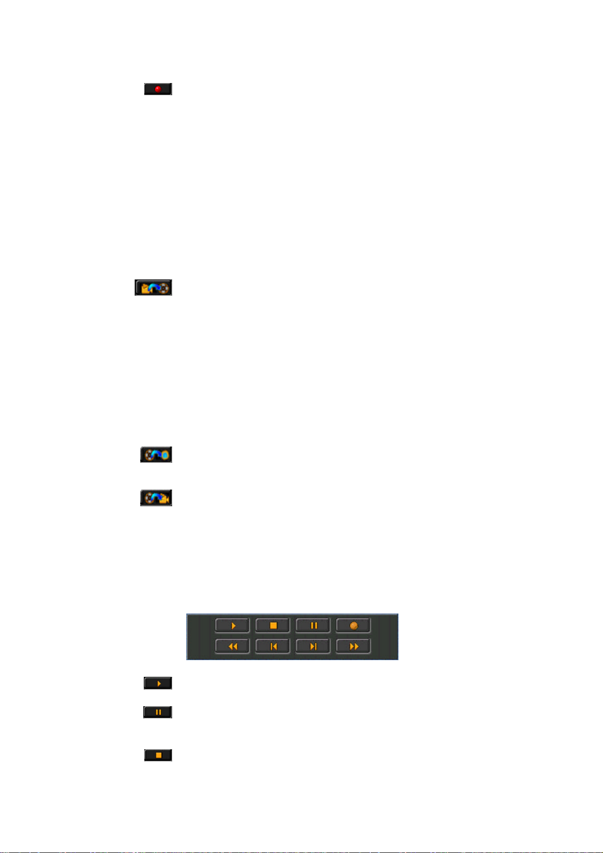
DV buttons
The DV buttons provide the basic functions of the DV Tools.
Tape Scan (New DV tape database):
Lets you scan a tape and create a New database. For more information on
scanning DV tapes, please refer to the section “Scanning a DV tape for clips”
on page 30.
Capture scenes from Capture Gallery:
Use the Capture command to start capturing (transferring the DV clips to the
hard disk).
Start Video Editing Application:
Launches Adobe Premiere.
Print to DV tape:
Use the Print to DV tape command to start recording the AVI clips. For
more information on recording your clips back to the DV tape, please refer
to the “Printing to DV” section on p. 36.
Status bar
44
The status bar shows the number of clips inserted in the Capture Gallery as
well as the running time and the expected file size.
The running time states the total duration of all clips which have been
inserted into the Capture Gallery in time code format
(hours:minutes:seconds:frames).
The expected file size states the sum of the file sizes (in MB) which will
result after you have captured the clips from the Capture Gallery.
Page 51

User´s Guide
TAPE GALLERY
A Tape Gallery displays all clips of a tape. So-called poster frames represent the clips. A poster frame is the first frame of a clip used for visual identification purposes.
A Tape Gallery is a kind of database which is created when you scan a DV
tape. The Tape Galleries are saved in the DV Explorer and can be opened by
double clicking on a name.
The buttons in the toolbar of the Tape Gallery let you open the Clip Info
window, display large posterframes, or display thumbnails.
DV DEVICE CONTROLLER
The DV Device Controller window allows you to remotely control your DV equipment so that you do not need to use the buttons on the device itself. It also contains a preview window, lets you capture video and print it back to tape and add trim points.
To open the DV Device Controller,
• in the Capture Gallery, go to the Tools menu and click DV Device
Controller.
—or—
• click on the Camera icon in the toolbar.
45
Page 52

miroVIDEO DV 200
Top section of the DV Device Controller
The top section of the DV Device Controller displays a preview of the
current video and the current time code. The preview quality depends on the
overlay capabilites of your graphics board.
(for more information, see page 50.)
This window also contains the buttons for capturing a bitmap (Snapshot),
saving digital video to hard disk (Capture), previewing DV AVI files on your
DV device and transferring saved files from hard disk to the DV video tape
(Print to tape).
46
Time code(top of DV Device Controller):
Displays the time code of the current video clip. The time code marks the
chronological position of a video frame and is given in the
hours:minutes:seconds:frames format. This time code is transferred by the
DV video device to the DV Device Controller.
Page 53
User´s Guide
From DV Device to Computer
(Left Side)
Live capture:
The Live capture button lets you capture video directly from the lens or from
your DV tape. If you want to capture video from the lens of your DV
camcorder, make sure that it is set to the Camera mode.
If you want to capture video from the tape, make sure that your DV device is
set to the VTR mode.
After you start capturing, a dialog box appears displaying the progress of the
capture process. To abort capturing, press the Cancel button. If you do not
abort capturing manually, the DVTools will save DV video to your hard disk
as long as enough storage capacity is available. After the capturing process is
complete, you can enter a drive and the directory where you want to save the
AVI file. The default drive is the one you selected, in the Preferences dialog
box (see page 36).
Capture (creating AVI file):
This button lets you create an AVI file from the current video clip. You can
only use this button after you set the in and out points for the clip boundaries
(like during tape scan). If you did not scan the tape and you want to capture
an AVI file from your tape, use the Live capture button (see below). If you
do not want to save the entire clip on the hard disk, you may want to set trim
points. These trim points mark the beginning and the end of the AVI file.
(See also the “Capturing” section on page 53.)
From Computer to DV Device
(Right Side)
Preview DV Output:
This button allows you to play back an AVI file to your DV device for
previewing.
Print-to-tape (recording AVI files back to the DV videotape):
Allows you to save the AVI file back to your DV videotape.
VTR controls
The VTR controls area lets you remotely control your DV device. The
controls resemble the controls found on your DV device.
Playback:
The DV device plays back the tape.
Pause:
The DV device stops playing back the tape, while displaying the current
frame.
Stop:
The DV device stops playing back the tape, the current frame will not be
displayed.
47
Page 54

miroVIDEO DV 200
Set To Record:
Allows you to set the DV device to record. Useful for e.g. PAL cameras that
do not have a record button for use in VTR mode.
Rewind/Play fast in reverse:
If the DV device is stopped, this button rewinds it rapidly. If the DV device
is in play or pause mode, this will provide fast reverse play with viewable
video.
Step back:
This button lets you jump to the previous frame.
Step forward:
This key lets you jump to the next frame.
Fast-forward/Play fast forward:
If the DV device is stopped, this button causes the tape to move forward
rapidly. If the DV device is in play or pause mode, this will provide fast
forward play with viewable video.
Trim points
If you do not want to capture the entire clip but only a section of it you may
want to define trim points (in and out points). It is only possible to add trim
points, if you scanned the tape. A clip is in this case the video footage
between the start of a shot and the end of a shot.
You cannot define sections extending beyond clip boundaries when you
opened the DV Device Control from within the Clip Info window.
These buttons let you define in and out points to define the start and end of a
section. Click on these buttons either during playback or in the pause mode.
You may also use the slider at the bottom of the DV Device Controller (jog
shuttle) to move the tape forward or to rewind it.
Start of clip:
Rewinds the current video clip to its beginning.
End of clip:
Moves the current video clip forward to its end.
Apply trims:
After you defined a section, click Apply trims.
48
Page 55

User´s Guide
Manual editing of the In and Out time code
The DVTools DV Device Controller allows for the manual (typed) entry of
trim point timecode by the user. Simply double click on either the In or Out
point time code window to bring up the Manual trim point entry window.
Enter in the desired trim In and/or Out point value and then click OK.
The trims will only be permanently saved in the clip using the Apply trims
button, if the videotape has already been scanned and if a database has been
created for it.
If you add trims in a clip you opened from the Tape Gallery, these trims will
be permanently saved for this clip until you change them.
If you add trims in a clip you opened from the Capture Gallery, the trims
will only be saved for this special Capture Gallery database.
The Clip length is the duration of the current section. If no trim points were
set, the duration of the whole clip will be displayed.
The File size displays the file size (in kilobytes) the current section will have
when being captured. If no trim points were set, the size of the whole clip
will be displayed.
You may delete the trims you set in the current clip by clicking the Delete
trims section. This restores the original clip boundaries.
Jog-Shuttle
The Jog/Shuttle slider is located at the bottom of the DV Device Controller
window. You can use it to search through a tape at different speeds to
accurately locate start and end frames for your clips. The Jog/Shuttle slider
duplicates the Jog/Shuttle editing wheels offered on VCRs. The rewind and
fast forward modes of the VTR controls scan in one speed, whereas the
Jog/Shuttle slider offers a variety of speeds.
When the slider is in the middle, the DV device is paused. Dragging the
control box to the left accesses the reverse shuttle speeds, while dragging it
to the right accesses the forward shuttle speed.
Not all DV devices support all of the functions possible with the DVTools
DV device controller. Please refer to your DV device's owner's manual to
learn what functions your DV device supports.
49
Page 56

miroVIDEO DV 200
Manually inserting video clips into the Capture Gallery.
The DV Tools identify recorded scenes on a registered DV Video tape by
date and time code information. Using the View menu and the command Add
clips to capture gallery the user is able to insert a video clip into the current
Capture Gallery.
Determine the tape you wish to capture the footage from (Current tape relies
to the tape which is currently in your powered camcorder). Click on the New
( ) button. Set the in and out point. Click on Apply. If necessary, define
further video clips. Click on Add in order to add the clips to the Capture
Gallery. The window Add clips to capture gallery supplies the commands
New, Rename and Delete. You can access them using the buttons in the
upper left corner or by clicking right into the editing area.
Rescanning tapes
If a tape has already been scanned before, the DV Tools will offer to rescan the
tape from the beginning or from any known clip. You can add footage to the DV
tape without effecting existing clips stored in the database. Select the clip you
would like to start from using the corresponding list box.
50
Page 57

User´s Guide
miroINSTANT VIDEO PLAYBACK
miroVIDEO DV200 Configuration
The miroVIDEO DV200 Configuration allows you to enable/disable options
s for using the DV200 with the miroVIDEO DC30 series board,
s for the display of the DV video, and
s for outputting the video via miroINSTANT Video on your computer
monitor.
The miroVIDEO DV200 Configuration tool is located in the
miroVIDEO DV200 Program Group.
By default, the Use Direct Draw Overlay Surface and the Use Direct Draw
Overlay Surface optios are enabled. The other options are disabled.
To exit the Configuration, click Close. If you changed the settings, the
changes will not be saved when clicking Close.
If you want to save the settings, click Save.
Optimized Display for miroVIDEO DC 30
If you want to record the DV video clips you captured with the DV200
board back to an analog video tape via the miroVIDEO DC30 (plus) board
or if you want to convert already existing DC30 clips inot the DV format
using Adobe Premiere, please select the
Optimized Display for miroVIDEO DC 30 option.
Use Direct Draw Primary Surface
To enhance the preview quality and the display quality in the Media Player,
you may want to enable the Use Direct Draw Primary Surface option. To
use this option, however, your graphics board has to support DirectDraw. In
general, state-of-the-art PCI graphics boards support an Overlay Surface.
For more information on the DirectDraw support, please refer to the manual
of your graphics board.
51
Page 58

miroVIDEO DV 200
If your graphics board does not support the Direct Draw Primary Surface
and the option is enabled, the video will be displayed on your computer
monitor but at a lower image refresh rate.
Use Direct Draw Overlay Surface
The DVTools provide a preview function which displays the video supplied
by your DV device or AVI files in a small window on your computer
monitor. You can also playback the AVI files created with the miroVIDEO
DV200 board using the Media Player.
To enhance the preview quality and the display quality in the Media Player,
you may want to enable the Use Direct Draw Overlay Surface option. To
use this option, however, your graphics board has to support DirectDraw. In
general, state-of-the-art PCI graphics boards with e.g. S3 Trio64 V+, Virge,
or Virge VX graphics processors support an Overlay Surface. For more
information on the DirectDraw support, please refer to the manual of your
graphics board.
If your graphics board does not support the overlay function and the option
is enabled, the video will still be displayed on your computer monitor albeit at
a lower image refresh rate.
If your graphics board supports Direct Draw but no overlay or a distorted
overlay appears, it may be for the following reasons:
Testing the
overlay feature
s The overlay does not work at the current display resolution. If this is the
case, try out another resolution and select a smaller number of colors. In
this case, close the window displaying the video and select another
resolution and another color depth.
s The graphics board's drivers does not support the overlay feature. Please
install the latest drivers for your graphics board.
It will not be readily apparent whether your graphics board supports overlay
or not.
To test whether your graphics board supports the overlay feature or
whether it does not, you can perform a simple test.
1. Make a screenshot of the window displaying your video by pressing the
<Alt> and the <Print> keys on your keyboard. The window containing the
video (DV Device Controller or Media Player) must be the active one.
2. Open an image application e.g. Paint from the Windows Program Group
Accessories.
3. From the Edit menu, select the Paste command.
If the video image looks like the one you captured, your graphics board does
not support overlay.
52
If a magenta-colored area appears, your graphics board does support an
overlay.
Display output on PC monitor
Enable this option if you want to output DV files on your computer monitor
which you created using miroINSTANT Video under Adobe Premiere.
Page 59

User´s Guide
miroVIDEO DV200 &
Adobe Premiere 4.2LE
ADOBE PREMIERE PROJECT PRESETS
In order to create a project in Adobe Premiere, you must first select a Project
Preset. By selecting a Project Preset, you select the preview and output
options for your movie.
After you start Adobe Premiere, the New Project Presets window opens.
The following Presets are offered:
DV200 NTSC -> DV200 NTSC:
Select this Project Preset if you use the NTSC standard and you want to
record the video files you captured and edited back to DV tape.
DV200 PAL -> DV200 PAL:
Select this Project Preset if you use the PAL standard and you want to
record the video files you captured and edited back to DV tape.
DV200 NTSC ->DC30 NTSC (720x480):
Select this Project Preset if you use the NTSC television standard and you
want to record your AVI files back to an analog video tape via the
miroVIDEO DC30 board. Your movie will be built with a resolution of
720 x 480 (corresponds to the studio standard CCIR 601). The horizontal
resolution is more precise than in the straight NTSC resolution (640 x 480)
and no time-consuming recomputation is required. The disadvantage of
recording video with this setting is that it will be slightly distorted when
being displayed on the computer screen, e.g., circles are not depicted as
circular.
53
Page 60

miroVIDEO DV 200
DV NTSC -> DC30 NTSC 4:3 (640 x 480):
Select this Project Preset if you use the NTSC television standard and you
want to record your AVI files back to an analog video tape via the
miroVIDEO DC30 board. Your movie will be built with the strict NTSC
resolution of 640 x 480. With this Preset, square pixels are generated, i.e.,
the image will not be distorted on the computer screen. The disadvantage of
this setting is lengthy recomputation time when building a movie.
DV200 -> DC30 PAL (720 x 576):
Select this Project Preset if you use the PAL television standard and you
want to record your AVI files back to an analog video tape via the
miroVIDEO DC30 board. Your movie will be built with a resolution of 720
x 576 (corresponds to the studio standard CCIR 601). No time-consuming
recomputation is required when building a movie. The disadvantage of this
setting is slight distortion on the computer screen, e.g., circles are not
depicted as circular.
DV200 -> DC30 PAL 4:3 (768 x 576):
Select this Project Preset if you use the PAL television standard and you
want to record your AVI files back to an analog video tape via the
miroVIDEO DC30 board. Your movie will be built at the strict PAL
resolution of 768 x 576. With this Preset, square pixels are generated, i.e.,
the image is not distorted on the computer screen. The disadvantage of this
setting is lengthy recomputation time when building a movie.
THUMBNAIL ACCELERATION
In Adobe Premiere, display of thumbnails is accelerated. For a flickerless
display in the preview, select the resolution 200 x 135 (NTSC) or 200 x 160
(PAL) for the preview mode.
In PAL, some image sizes may form black stripes on the right and left
edges of the image. These stripes have no effect on your finished movie,
since they are not in the viewable area.
54
Page 61

User´s Guide
miroINSTANT VIDEO 2.0
General
miroINSTANT Video accelerates video productions providing smart and
powerful functions to edit, preview and print-to-tape of DV encoded
material. Complete productions can be recorded back to tape selecting the
Synchronous start option.
In the past, in order to output your project or to get a high-quality preview,
you had to ”make a movie”. During this time-consuming process, the editing
application would copy all of your source material into a new AVI file. This
would happen not only for the areas where you applied an effect or a
transition, but for the entire length of your production. Not only did this
take a considerable amount of time, but it also requires the same amount of
disk space as the clips you already captured. In addition, your output was
limited to a maximum size of 2 GB (2048 MB) because of a restriction of
Video for Windows.
miroINSTANT Video changes all of this. Instead of ”making a movie”, you
may now invoke miroINSTANT Video, which will scan through your project
and create AVI files only for the areas where you applied effects or
transitions. This is—depending on the complexity of your project—up to
twenty times faster and will not waste disk space by copying material that has
not been modified.
But miroINSTANT Video goes even further—it will play back the resulting
range of AVI files automatically and seamlessly right from the construction
window timeline by automatically accessing the miroAVI Cache. Thus, the
fact that you did not ”make a movie” is totally transparent. miroINSTANT
Video does not require that you keep track of the separate AVI files, it does
it for you.
Even better, with miroINSTANT Video, your production may be as long as
your disk space allows (up to the 60 minute limit of Adobe Premiere). As
there is no one file that everything is being copied to, there is also no 2GB
limitation.
In most cases, the miroINSTANT Video plug-in should be installed on your
system. If not, you deselected the miroINSTANT Video option in the
installer. If this is the case and you want to install miroINSTANT Video
now, see the “Installing the DV200 software later” chapter on page 22.
55
Page 62

miroVIDEO DV 200
Using miroINSTANT Video 2.0
miroINSTANT VIDEO lets you do either of two things:
s You can preview your project on your PC monitor or a connected DV
device.
s You can record your project to DV tape.
If you do not want to record your project to DV tape but just want to have a
look at the preview, use the DV200 Configuration tool to select the Preview
option. The DV200 Configuration tool is located in the DV200 Program
Group.
To use miroINSTANT Video in Adobe Premiere, just do the following:
1. After you launched Adobe Premiere, select a suitable Project Preset (see
p. 53).
2. Create an Adobe Premiere Project. Open the AVI files you want to
include in your project. Edit your project. For further information on
Adobe Premiere, please refer to the Adobe Premiere documentation.
3. After you finished editing, save your project.
4. From the Make menu, select Output Options and Full Size Frame.
Before using miroINSTANT Video, it is required to save the project file.
Always select the Full Size Frame option in the Output Option dialog!
5. To make your movie, click on the File menu and select Export.
6. Select miroINSTANT Video.
56
Page 63

User´s Guide
Buttons
7. If you want to preview your project, click on the button.
If you want to record your project to DV tape, make sure that your DV
device is set to the VTR mode and that you inserted a new DV tape.
Enable the Intro option from the menu. To start recording, click the
button in miroINSTANT Video. Now the intro will be displayed which
allows you to click on the Record button on your DV device at the
appropriate time. After the intro is over, click on the Record button on
your DV device.
Buttons and keyboard commands in miroINSTANT Video
This button starts/stops the video playback.
This slider allows you to scroll the movie and to jump to clip ends.
A counter shows the current position and the overall length of the movie (in
frames or as time code). If the video jerks during playback, the counter
shows the number of the dropped frames.
The Intro command lets you switch the intro movies on/off.
The Auto repeat command repeats playing back the movie.
The Synchron start button starts the DV recording device automatically
when the movie begins.
57
Page 64

miroVIDEO DV 200
Keyboard
commands
Using the keyboard, you can jump to the next/previous frame or to the clip
start/end.
Key Function
Next frame
Previous frame
UP ARROW key Previous clip
DOWN ARROW key Next clip
The connected DV device must be able to accept data from the PC (DV IN).
Some of the PAL devices available in Europe do not support a playback back
to the camcorder.
We recommend to test the ability of sending data back to the camcorder:
1. Insert a tape into your DV camcorder / VCR. Turn the device on and
make sure it is in VTR mode (camera mode will not support DV IN).
2. Start the DV Tools and select the Device Controller.
3. Click on the Preview button and select a DV encoded AVI file. It should
match the video format of your DV device (PAL / NTSC). If you don’t
have captured any material yet, you can select the intro -files
P720576c.AVI ( PAL) N720480c.AVI (NTSC) from the MVintro folder.
These files got copied during installation under the selected DV200 install
folder. Do not use the files directly from CD because of insufficient data
rates.
4. Start the preview by clicking OK.
Reduce color
depth to 16 bits
Close other
Applications
Graphics
Adapter
PCI Latency
PCI Streaming
You should see video on the camera’s display or on a TV monitor that is
hooked up to your camcorder.
Performance Optimization
The playback of DV encoded files to the PC monitor or to the connected DV
camcorder can be optimized:
Reduce the color depth of your graphics adapter to high color (16 bits).
(Click right on the Windows desktop, command Properties, Settings tab,
Option Colors.)
Close all applications while working with Premiere or the DV Tools. It is
recommended to use either the DV Tools or Premiere. Do not use both at the
same time.
Some graphics adapters may disturb a 1394 transfer back to the camcorder
due to longer PCI bus cycles. It might happen, that the PCI bus is nearly
blocked for other operations. Adapters utilizing the S3 ViRGE-chipset may
cause such problems.
Check if your system BIOS supports different values for PCI Latency.
Choose the highest value the BIOS is offering.
If your system BIOS supports PCI Streaming it is recommended to turn it off
if you see problems transferring data back to the camcorder.
58
Page 65

User´s Guide
Capture disk
selection
If you have different hard disks installed in your system, check the playback
of video from different drives. Always select a separate disk as capture disk.
Make sure this disks is not used as virtual memory or is not used to store
temporary files.
WORKING WITH miroVIDEO DV200 AND A BOARD OF THE miroVIDEO DC30 SERIES
DV200 and DC30 are using different video compression algorithms to store
video data. Compression and decompression functions are required to work with
this material on your PC. These functions are supported by CODECs. The
miroVIDEO DV200 supports DV format while miroVIDEO DC30 is using
MJEG. Please note that both products can only work with material that is stored
using the dedicated compression format. If you like to use material on a different
device you need to transcode the video from one the original format to the target
format.
Working with
Adobe Premiere
If you are using DV200 and DC30 in one system, a Premiere video
production can either be played back using DV200 or DC30. The Premiere
project settings allow to determine the CODEC you want to use as the target
compression format. Based on this setting either DV200 or DC30 hardware
will be used. You can also use the project settings that come with your
installation.
All clips used for a specific project must be stored using the video
compression format supported by the selected project setting. Clips that are
recorded in a different format need to be transcoded to the target format.
You can use Premiere (Make Movie) to force this transcoding.
Generating the preview files required to use miroINSTANT Video for
playback does not transcode video clips stored in a different compression
format. Preview files will only be generated for filters or transitions used in
the project.
If a project contains video clips with different compression formats you must
select a filter for each clip that differs from the target format. Doing so will
force Premiere to generate the required temporary files that can be used for
playback utilizing miroINSTANT Video.
miroINSTANT Video will generate an error message, if a clip in the project
does not match the project settings.
It is recommended to transcode all clips that should be used for a specific
project before using them. Use a different project for the transcoding part.
The project settings selected in Premiere also define the resolution. For
playback using DV200 the horizontal resolution is 720 pixels. For DC30
projects different resolutions can be selected. A transcode will also resize the
image to the chosen target resolution.
59
Page 66

If you import clips that do not match the selected project settings, the render
time might be very long and the output may contain artifacts.
Playback to an analog device using miroVIDEO DC30
In Premiere select the project preset ”DV200PAL -> DC30PAL”, ”DC30NTSC
DC30NTSC”. ,”DC30PAL -> DC30PAL”, or ”DV200NTSC ->
->
DC30NTSC”. This preset defines the output format (can be viewed selecting
Details) as well as the MJPEG coding format.
Use the DV200 Configuration program and select Optimize display for
miroVIDEO DC30 if you want to transcode from DV to MJPEG.
You need to deselect this option after the transcoding is completed.
If you want to playback the video using the MediaPlayer or the Premiere
controls you need to generate the file using Make Movie.
If you want to output files using miroINSTANT Video that are not in MJEP
format you must select a filter for each file. Premiere will be forced to
transcode this file. Note that this is very time consuming.
Playback to a DV device using miroVIDEO DV200
In Premiere select the project preset ”DV200PAL -> DV200PAL”,
”DC30PAL -> DV200PAL”, ”DV200NTSC -> DV200NTSC ” or
”DC30NTSC -> DV200NTSC”. This preset defines the output format (can
be viewed selecting details) as well as the DV coding format.
Use the DV200 Configuration program and select Optimize display for
miroVIDEO DC30 if you want to transcode from MPEG to DV.
You need to deselect this option after the transcoding is completed.
If you want to playback the video using the media player or the Premiere
controls you need to generate the file using Make Movie.
If you want to output files using miroINSTANT Video that are not in DV
format you must select a filter for each file. Premiere will be forced to
transcode this file. Note that this is very time consuming.
60 miroVIDEO DV 200
Page 67

User´s Guide
miroVIDEO DV200 &
Adobe Premiere 5.1
This chapter describes the steps required to produce high quality video with
this hardware / software combination. Please note that this document
provides general information. You will find additional product specific
information in the release notes that comes with the Adobe Premiere 5.1
compatible drivers for your Pinnacle Systems miroVIDEO DV200. Please
make sure to read the ReadMe file in addition to this User's Guide.
Adobe Premiere 5.1
Adobe Premiere 5.1 is a new version of Adobe's popular video editing
application. To make best use of it you will need Adobe Premiere 5.1
optimized driver software for your DV200 (included). This especially applies
to the use of miroINSTANT Video, as the Adobe Premiere 5.1 version of
miroINSTANT Video is significantly different from the version for Adobe
Premiere 4.2 and 4.2LE.
The basics remain, though. With Adobe Premiere 5.1 and a compatible
Pinnacle System miroVIDEO editing board you get a highly productive,
professional video editing solution.
If, for any reason, you are using Adobe Premiere 5.0, Pinnacle Systems
highly recommends that you update your system to Adobe Premiere 5.1
before installing the DV200. Our drivers have been optimized for Premiere
5.1 and may not deliver the same level of performance with Premiere 5.0. An
update to Premiere 5.1 from Premiere 5.0 can be obtained through Adobe
Systems, Inc. (see http://www.adobe.com).
61
Page 68

miroVIDEO DV 200
INSTALLATION
Using Adobe Premiere 5.1
Install Adobe Premiere 5.1 on your PC. Please note down in which directory
you install it. Next install your DV200 and its Adobe Premiere 5.1
compatible software as described in the respective manual.
PRESETS
If the miroVIDEO installer asks you for the location of the Adobe Premiere
5.1 directory (on Custom installation or if the installer cannot find the
Premiere 5.1 directory), enter it from your earlier note. See the ReadMe file
for driver installation details
The presets included in the delivery scope contain all settings that guarantee
an optimal adaptation of the DV200 and Adobe Premiere.
1. To install an appropriate preset, start Adobe Premiere 5.1 via the Start
menu and the program group Adobe.
The New Project Settings window appears:
62
Page 69

User´s Guide
2. Click the Load button in the New Project Settings dialog box.
The Load Project Settings window appears.
3. Select one of the DV200 settings that have been installed.
For further details, please refer to the User’s Guide.
4. Click OK to use the selected setting. The Premiere 5.1 project settings are
now adapted to your DV200. You will be returned to the New Project
Settings window. Pinnacle System strongly recommends not to change
any further settings in the New Project Settings window!
5. Click OK to finish the loading of the preset.
If you don't use one of the presets supplied for your Pinnacle Systems
DV200, or change the Adobe Premiere 5.1 settings manually, the DV200
and miroINSTANT Video 5.1 may not work properly.
The supplied presets automatically set the output resolution (PAL / NTSC),
rendering field order, audio format and other Adobe Premiere 5.1 parameters
to values proper for working with your DV200.
63
Page 70

miroVIDEO DV 200
CAPTURE VIDEO WITH ADOBE PREMIERE 5.1
General
Adobe Premiere 5.1 offers video capture capabilities. In this chapter we
describe how you can capture video from within Premiere 5.1.
Below are descriptions of Device control and Capture functions from within
Adobe Premiere possible with the DVTools plug-ins. Even though the plugin modules ship with every DV200, Adobe Premiere 5 LE does not allow for
their use. An upgrade to the Full Version of Premiere will be required to use
these functions.
Preparing the
capture
Before you are able to capture video, you need to select the capture drive.
This is the drive to which your AVI files will be recorded. It should be fast
enough and offer enough free space for digital video recording. For detailed
information on the required features of your hard disk, please refer to the
“System requirements” section in this User’s Guide.
1. To choose your Capture disk, select Preferences/Scratch Disk from the
Adobe Premiere File menu.
The Preferences dialog box will appear, allowing you to choose the
location for your files:
64
2. Select fast hard drives for all three types of files, Temp/Captured Movies,
Video Preview Temps and Audio Preview Temps and click on OK.
Page 71

User´s Guide
Capturing Video with miroVIDEO DV Capture
With miroVIDEO DV Capture, you have purchased a recording module that
functions with Adobe Premiere 5.1 under Windows 95, Windows 98 and
Windows NT.
1. Connect a DV device to the DV200 as described in the manual. Switch on
the device and select the VTR mode.
The DV200 settings cannot be modified if no DV device is connected and
operable.
2. After loading one of the appropriate settings, open the New Project
Settings dialog box (menu Project, command Settings... and Capture
Settings..., even if you do not want to change any settings.
This is required to make Adobe Premiere 5.1 switch to the DV200
capture module. If you do not do this, the capture module may not be
utilized. The DV200 does not require any further settings. The video
format (PAL or NTSC) and the audio settings are set automatically
depending on the DV device and the video footage used. It may happen
that these settings do not match your current project settings.
3. Once you have made the settings, close the New Project Settings window
by clicking OK. You can now transfer video clips to your hard disk using
the Premiere 5.1 Movie Capture function. To do this, use the Capture and
Movie Capture commands from the File menu.
65
Page 72

miroVIDEO DV 200
DEVICE CONTROL WITH ADOBE PREMIERE 5.1
The DV200 board can control DV devices connected via the 1394
connection, and can query information from the device like time code, for
example. The device control function of the DV200 is capable of controlling
devices that are connected to the board via the 1394 cable.
Before you begin controlling your DV device, you must configure the device
control and Premiere for your device. In Premiere, click the File menu and
then the Preferences command. Select the Scratch Disks / Device Control
command.
1. In the device control list box, first select the entry:
miroVIDEO DV device control.
2. Then click the Options button.
By doing so, you call up a dialog box in which you can define the settings
needed to configure your system. If you have established a correct
connection to the DV device, Premiere will save these parameters for later
Premiere sessions. You must reconfigure your options if you select a
different kind of device control or if the "No 1394 device found" warning
should appear.
If no miroVIDEO DV device control entry is listed in the list box, check
whether the file X-DV200.prm is in the corresponding Adobe folder. If
this is not the case, quit Premiere, reinstall the DV200 drivers for Premiere
5.1 and restart Premiere.
The Select AV device dialog box appears when you select DV200 device
control for the first time. If this is not the case, click the Options button to
configure device control.
66
Page 73

User´s Guide
Configuring device control
Here, you configure the device control for your computer system and your
DV device. The device control identifies the connected DV device if it is
connected properly. You can view details about the device by clicking the
Edit device info... button.
When a device is detected for the first time, the device control runs a test to
determine the supported functions. You can then take recourse to these
functions when editing video material, especially when recording or when
producing DV tapes.
Operating the device control
The 1394 device control of the DV200 supports the following functions:
s Frame forward, frame backwards
s Export to DV tape, insert edit
s Position information (the time code)
s Locate commands , seeks to a specific time code
s Basic functions
(Stop/Rewind/Fast Forward/Playback/Pause)
s Batch capture, in combination with any capture plug-ins
s Jog Shuttle functions
The device controls are accessible in various Premiere windows. Consult the
Premiere user manual for details on how to control a device from Premiere.
*
These functions are not supported by all DV devices.
*
*
*
67
Page 74

miroVIDEO DV 200
Export to DV tape
For record and insert cuts you need DV devices that support these functions.
Consult your video recorder/camcorder user manual to find out which
functions your device supports. The device control will determine your
device's scope of functions and will only offer those functions that your
device supports.
Although the device control supports functions such as record and insert
cuts, no guarantee of clip playback precision can be given. It is Premiere that
plays the video clip, and not the DV200 device control. Please consult Adobe
Premiere's technical support if you should find there are irregularities in video
playback.
Under Premiere 5.1, the DV200 supports export of video data to tape.
1. In Premiere 5.1, click the Export and Export to Tape command in the File
menu.
The following dialog box appears:
68
Certain device control options can be activated.
Export options
s Activate recording deck
Select the Activate recording deck option if you want to use the device
control to synchronously set the connected DV device to the record
mode. This is required to record video data to tape.
s Insert Edit settings
The Insert Edit settings allow a frame accurate insert cut if the
connected DV device is supporting this function.
Page 75

User´s Guide
Insert edit
s Time code
You can enter a start time code that is used for the current project.
s Preroll
The Preroll field allows you to fine tune the synchronous start of
playback and recording. Note that for a lot of known DV devices the
Preroll field is preset with a value that allows frame accurate insert
cuts.
Audio output options
s Output 32kHz audio files with 12 Bit
Audiofiles recorded with 32kHz, 16Bit can be played back to tape
utilizing either the 16Bit or the 12Bit format. Using the 12Bit format
both audiotracks on a DV tape will store the identical data. You can
then choose one of those tracks to overwrite the data with other sound
material. Using the 16Bit resolution will not allow you to use the
second audio track.
s Use “Locked Audio” format
This feature is only enabled for Sony DVCAM devices such as DSR30P. For all other models this checkbox is disabled.
Once you have made the required settings, Premiere switches to the playback
mode to prepare the required operations and starts playback. During
operation your PC screen will be blacked. After playback, Premiere switches
back to the edit mode. You may have to repeat the settings just defined
because they are not stored.
General remarks
You can use the following steps as a guideline for fine tuning the export to
tape function.
s Stripe a DV tape, the tape should contain continuos time code. Switch
your DV device into the Camera mode, rewind the tape and while the lens
is darkened push the record button until the tape is completely recorded.
s Insert marked video frames at the beginning and at the end of your video
production to identify each frame. We recommend you use a frame
counter for each of the first and the last second of the video.
s Select Export-to-tape as described above.
s Enter a start time code. Save the in and out time code to a piece of paper
s Hit Enter to start operation.
s After the export-to-tape operation is complete use the miroVIDEO device
control (you must select Movie capture) or the remote control to seek to
the start time code. Check the discrepancy between the first recorded
frame and the desired tape location. This difference should be used the
next time you repeat this operation in the preroll setting.
s Check that recording started with the first marked frame of your project.
s Check that recording stopped at the out-time code.
s Repeat this procedure until you find the preroll value that works the best.
69
Page 76

miroVIDEO DV 200
If you find that recording started or ended inaccurately we recommend that
you use black frames at the beginning and at the end of your video
production to ensure that the total production is recorded.
Note that the export-to-tape accuracy depends on the DV camcorder or
VCR that is used. Pinnacle Systems cannot guarantee that this function is
supported by all DV devices.
We also want to remark that some DV devices activate the analog audio
signal with delay. It can happen that there is silence during the first second.
But the data is put onto the tape properly.
Discrepancies
Suppose that you wanted to start the cut at time code 01:00:00:00. What
was the frame number at the start of the cut after the project was transferred?
If it was at 01:00:00:01 or more, the clip was started too early. Therefore,
you should enter a smaller number of frames under “Pre-roll”. Repeat the test
until you arrive at a satisfactory result.
If the first frame at the start of the cut was black or if you saw repeated
frames, the clip was started too late. In this case, you must set a higher
number of frames for the “Pre-roll”.
Premiere 5.1 and time code
Internally, Adobe Premiere assigns frame numbers to your recorded clips
instead of genuine time codes (this applies to all versions of Adobe
Premiere). Frame numbers are random, automatically incremented numbers
that, above all, facilitate the work of programmers. However, as one and the
same frame number may correspond with one of three different time code
values, depending on the time code format used, problems may be
encountered if the correct time code format is not set. This may be relevant
in the following situations:
s You manually enter a batch list with the wrong timed code format, or
s You use Premiere's logging function without device control in the video
recording window (Movie Capture).
s The time code format in the recording window does not match the current
tape format that is currently being logged.
This may lead to various errors like the following:
s "Time code not found" error message
s The time code on your clip is offset by a few seconds
s Recorded clips begin with a wrong time code
70
The reason for this is fairly basic. If you choose a time code of 01:00:00:00
for the starting point, Adobe Premiere may interpret this value depending on
the format of the digitized video:
s NTSC (NDF time code) 108,000 frames
s NTSC (DF time code) 107,892 frames
s PAL 90,000 frames
Page 77

User´s Guide
A new feature in Premiere 5.1 is the ability of displaying the time code of
your clip and monitor windows in different ways, some of which may be
confusing. In turn, this may lead to errors if you attempt to calibrate your
time code discrepancy or to manually enter a batch capture list. Premiere 5.1
allows you to adapt the time format of the monitor or clip window.
However, this does not affect the video recording window. This is a general
setting that does not change automatically when you load a clip with a
different format. The fact that the time base of a clip can also be displayed
incorrectly makes it difficult to determine the time code format of a clip. If
you wish to determine the actual time code format of a clip, you must call up
the Properties for command from the File menu while the clip in question is
displayed in the monitor or the clip window. You will find further
information on this topic in the Adobe Premiere 5.1 manual.
DV time code
Drop frame
time code
DV devices use a Drop Frame or DF time code (NTSC only). It cannot be
set to a specific default, i.e. new tapes always begin at 00:00:00:00.
Nevertheless, this is exact and returns clear values for single frames. When
working with DV material, select “Drop-frame time code” in the Premiere
project settings.
NTSC video (the US standard) is based on 30 frames per second almost. The
exact frame rate is 29.97 frames per second, which corresponds to an error
of .3% per second. This is why video engineers developed the DF system,
where 2 frame numbers each minute – with the exception of each 10th
minute – will be skipped. Actual video frames will not be skipped, just the
numbers in time code used to count them. One important reason for the use
of the DF time code is that the timing of long videos will be more precise.
In figures, it looks like the following:
Non Drop Drop
00:01:00;00
00:01:00;01
⇒ 00:01:00;02
⇒ 00:01:00;03
Please note that this applies only to every 1st, 2nd, 3rd, 4th, 5th, 6th, 7th, 8th and
9th minute, but not to the 10th, 20th, 30th, 40th, 50th or the 0 minute.
71
Page 78

miroVIDEO DV 200
miroINSTANT VIDEO 5.0
What is miroINSTANT Video 5.0?
miroINSTANT Video 5.0 is a playback module for Adobe Premiere 5.1 that
works with certain Pinnacle Systems miroVIDEO editing boards
(miroVIDEO DC30 plus, miroVIDEO DC50 and miroVIDEO DV200 are
currently supported). It requires Adobe Premiere 5.1 compatible software
drivers for the board.
There are some differences in the miroINSTANT Video 5.0 operation
depending on the Pinnacle Systems miroVIDEO editing board you use.
Please see the board specific sections later in this document and the readme
file that comes with your Adobe Premiere 5.1 compatible drivers. If you are
used to working with miroINSTANT Video with Adobe Premiere 4.2, see
the Changes From Previous Versions section.
This section assumes that a DV device is properly connected to the DV200
and is powered on. Several times the statement will be made that “video will
play through the DV output to the TV” or “the video will play through the
TV Out”. These assume that the video will pass through the connected DV
device to the video monitor or TV.
Major Benefits of miroINSTANT Video 5.0
When editing videotapes using Adobe Premiere 5.1, the use of
miroINSTANT Video 5.0 offers three major advantages:
s Productivity is increased by greatly reducing (up to 90%!) the amount of
rendering time required to output your project after editing is completed.
Instead of rendering the whole project, only effects and transitions are
rendered.
72
s Valuable hard disk space is saved (up to 50%!) since only effects and
transitions are rendered. Video segments that are not effected are not recreated and the original clip is used.
Page 79

User´s Guide
s The maximum duration of your productions is increased. Without
miroINSTANT Video 5.0 the whole production must fit into a single AVI
file, limited to a maximum size of 2 GB. This would only allow a
maximum project duration of less than 10 minutes when working at a data
rate of 3.6 MB/s. Using miroINSTANT Video 5.0, the maximum project
duration is that of the Adobe Premiere timeline, 3 hours. This makes long
format work on a PC possible.
System requirements for running miroINSTANT Video 5.0
To make use of miroINSTANT Video you need a PC system that fulfills both
the system requirements for running Adobe Premiere 5.1, see Adobe's
documentation and that of your Pinnacle Systems DV200. You also need a
graphics board capable of showing video overlay in combination with your
DV200 (see the release notes and the compatibility section on the Pinnacle
Systems web site at http://www.pinnaclesys.com and also the board specific
sections at the bottom of this document for more information).
How to use miroINSTANT Video 5.0
When editing a project with Adobe Premiere 5.1 , miroINSTANT Video
must be selected as the Editing Mode in the General dialog(menu Project,
command Settings and General). This is set automatically when using a
DV200 preset.
Open a new Adobe Premiere project using one of the DV200 presets, and the
miroINSTANT Video window will appear (See your manual and the readme
file for when to select which preset).
If a project is generated using one of theDV200 presets the check box Print
to DV device is displayed at the bottom of the window to allow a dynamic
switch between output to
s a connected and enabled DV camcorder or VCR
s the PC monitor using the DV200 Software CODEC
Because the DV200 does not provide a hardware DV CODEC you must
select an option since a simultaneous output to the DV device and the PC
monitor is not supported.
miroINSTANT Video 5.0 will now remain active and will handle smooth
video playback using the DV200.
Note that Adobe Premiere 5.1 projects must fulfill certain conditions to be
compatible with miroINSTANT Video 5.0 and the Pinnacle Systems DV200
(See the ”Limitations” section in this document). With miroINSTANT
Video, some things in Adobe Premiere work other than described in the
Adobe Premiere manual. Please read the miroINSTANT Video 5.0
documentation for important details.
73
Page 80

miroVIDEO DV 200
If you ever install Adobe Premiere 5.1 after having installed the DV200
driver software, you must re-install miroINSTANT Video 5.0 and the Adobe
Premiere 5.1 preset files—otherwise video playback with Adobe Premiere
5.1 will cease to work.
How does it work?
Whenever you play video clips or parts of the timeline in the Adobe Premiere
5.1 monitor window, miroINSTANT Video 5.0 does two things:
s It plays back the video using the DV200, so that it can be watched on a
TV, connected video monitor, or printed to tape.
s It makes sure that all source clips and rendered effects play back
smoothly, without interruptions between individual AVI files. This way,
the playback from the timeline can be directly printed to tape.
Without miroINSTANT Video 5.0, you would encounter stuttering and
dropped frames during the timeline playback. You would have to render the
entire project before you are able to print it to tape.
You can start the miroINSTANT Video 5.0 playback by hitting the <Enter>
key after selecting the work area you want, and activating the monitor or
timeline window. Hitting the <ESC> key or clicking on the Stop button will
stop the playback.
In the Adobe Premiere 5.1 documentation, this way of playback is called
“Preview”. When using miroINSTANT Video 5.0, this “Preview” mode
works at full quality and can be the output and print to tape mode as well.
miroINSTANT Video window
This window indicates that miroINSTANT Video is active.
When miroINSTANT Video 5.0 is installed, selected as the Editing Mode
and active (see above), the miroINSTANT Video window is visible. It is
displayed in front of all other Adobe Premiere 5.1 windows. The window
indicates that miroINSTANT Video 5.0 is active and will be used for
playback.
Film strip
Below the Pinnacle Systems logo there is a horizontal film strip. This acts as
an indicator for the playback status. If all images in the strip are black, then
the whole work area can be played by miroINSTANT Video 5.0.
In this case the project is ready to be printed to tape.
74
Page 81

User´s Guide
If some of the film strip frames are red, then some parts of the project can
not currently be played by miroINSTANT Video 5.0. If you scrub or play,
these parts will not show on the video output of your DV200. This will not
affect the output of a work area selection that does not contain segments that
have not been rendered.
To ensure the whole project is ready for output, you have to activate the
Adobe Premiere 5.1 preview function, i.e. by hitting the <Enter> key.
Audio output through miroINSTANT Video 5.0
Speaker symbol
Status line
miroINSTANT Video 5.0 shows by the speaker symbol whether the audio
tracks are played by miroINSTANT Video or directly by Premiere.
If the speaker symbol is not crossed out this indicates that the audio track is
played completely by miroINSTANT Video. In this instance the audio will be
sent to the DV device through the DV port and may be recorded to tape. The
audio will not be sent to the computer sound card.
A crossed out speaker symbol indicates the audio will be played by Premiere.
Premiere will play the audio itself when the audio tracks of the project are
not continuous, that is when there are gaps in the audio track. The audio will
be sent to the sound card of the computer and will be heard to through the
speakers of the computer, if connected. The audio will not be sent to the DV
port and will thus not be heard through the DV device nor will it be recorded
to the DV tape.
For more detailed information on why the speaker symbol will be crossed out
or not, please see the Audio Output section under Modes of Operation.
Normally, there is a status line at the bottom of the window that shows
different information depending on what mode of operation miroINSTANT
Video 5.0 is currently in. The status line is not visible if the window has been
minimized (see miroINSTANT Video menu below).
75
Page 82

miroVIDEO DV 200
Dropped frames
Indicator
If you are currently playing parts of the timeline, meaning that video plays in
the right video window within the Adobe Premiere 5.1 monitor window, the
status line shows the number of video frames that have been dropped during
the current playback. For smooth playback this number must be zero. If the
number of dropped frames is not zero, see the troubleshooting section below.
This message will stay in the status line until another action is performed.
miroINSTANT
Video menu
Audio
scrubbing
By moving the mouse pointer to any part of the miroINSTANT Video
window and clicking the right mouse button, you can activate the
miroINSTANT Video 5.0 menu. There are three menu items.
By default, audio scrubbing is switched on. This means if your project
contains audio you will hear the audio playback not only when playing clips
or the whole project, but also when scrubbing within the project (see Adobe
Premiere 5.1 manual for details on scrubbing and playing). This is the
standard Adobe Premiere 5.1 behavior, but it results in a performance loss
when scrubbing sections of audio that haven't previously been rendered (see
the Adobe Premiere 5.1 manual for details on audio rendering and how to tell
which parts have been rendered. Audio playback during scrub will be heard
through the computer sound card.
Help
Minimize/
Restore
If you switch off Audio scrubbing in the miroINSTANT Video 5.0 menu you
will only hear audio when playing clips or the project, not while scrubbing.
You can access the miroINSTANT Video 5.0 online help by selecting the
menu item Help from the miroINSTANT Video menu. Please do this if you
have any questions or problems using miroINSTANT Video 5.0.
The third item in the menu is used to change the size of the miroINSTANT
Video window. If the window is at normal size, the menu item is named
Minimize, and will reduce the window size so that only the window title bar
remains visible.
If the window is at minimized size the menu item is named Restore, and will
bring back the window to normal size. You may keep the miroINSTANT
Video window minimized during editing to have the maximum space
available for other windows, and restore it to normal size for printing your
production to tape in order to see the dropped frames information.
76
Page 83

Video output
Modes of operation
In Adobe Premiere 5.1 there are many modes of video display. You can
play, scrub or preview, use the trim or slip/slide tools, the monitor window
can be in single view or dual view mode with attached or detached controls,
and many more. The Adobe Premiere 5.1 documentation describes all of
these modes without reference to miroINSTANT Video.
When using miroINSTANT Video, there is the additional video output to
your TV / video device. This is active most of the time, but not always. In
addition, the PC screen display is different from the standard Adobe
Premiere 5.1 behavior in some cases.
Details: (“shown on TV” means output by the Pinnacle Systems DV200 to
connected video devices and/or screens):
When scrubbing using the left set of controls in the monitor window,
video is shown on the PC screen and on TV simultaneously.
When using the trim mode or the slip and slide tools, the video is shown
on the PC screen only.
When outputting the timeline (<Enter> key) or playing the timeline after
you called the 'Render Selection' function, the timeline content will play
through the DV port to the TV provided that the “Print to DV device”
function has been selected. Otherwise the output is effected on the PC
monitor. The DV200 output signal will be continuous.
Audio output
When you scrub or play parts of the timeline, the output depends on the
timeline content: If you scrub through parts / effects that have not been
rendered by Adobe Premiere yet, there will be no TV output of the effect
and only one of the source clips will be shown.
All parts of the timeline that do not need rendering or have already been
rendered will be scrubbed on the PC screen and on TV out.
When the source and program monitors are linked, the content of the
active monitor will be shown on the PC screen and on TV out, the other
monitor will display on the PC screen only.
The audio parts of the clips and projects you play back with miroINSTANT
Video 5.0 are output using two different devices: One is the DV200,
outputting audio through it's digital connectors as part of the standard DV
data during full playback. The other one is the standard Windows audio
device (i.e. your Soundblaster card) which will play back audio for scrub or
for items that have not yet been rendered by Adobe Premiere.
During priview, audio is output through the DV200 to a connected and
operating DV device when you:
Have activated the “Print to DV device” function
Play an AVI file that is compatible with the DV200 using the source
monitor or a clip window.
Do a preview playback of parts of the timeline, with all the audio in the
work area having already been rendered by Adobe Premiere 5.1 .
User´s Guide
77
Page 84

The audio is output through the standard audio device in all other cases. The
main reasons being:
No DV device is connected to DV200 or this device is not operating.
The export option “Print to DV device” is deactivated.
You scrub and audio scrubbing is not switched off in the miroINSTANT
Video menu.
You play a clip in the source monitor or clip window that has a format
incompatible with the DV200.
Where one or more audio segments in the segment to be played has not
been rendered by Premiere.
In certain circumstances you may find it hard to understand how the audio
gets processed. Basically it is quite simple, every time a clip is processed in
the right monitor the following will happen:
miroINSTANT Video gets a call from Premiere to play a certain segment
of the timeline.
It checks whether audio temp files are existing for the whole duration of
this segment.
If YES, the audio is handled by our drivers with lip synchronization.
If NO, Premiere handles the audio playback, using the default audio
device. In this case with no guaranteed lip synchronization.
Playback
Segments
Export Movie
Settings, Range
If Print to DV device is selected and the audio is not handled through
miroINSTANT Video you will find that the audio is played using the default
audio device while the video gets displayed on the connected DV device. In
this case the audio is about 18 frames ahead of the video stream due to
required buffering of the signal sent through the DV port.
The beginning and end of the segment depends on what you do:
hitting Return plays the work area,
hitting Space or clicking Play plays from the current position to the end
of the last clip in the timeline,
clicking Play to out plays from the current position to the timeline out
point (acts like Play with no out point set),
clicking Loop playback loops between the timeline in and out points.
The existence of audio temp files can be identified as gray bars on top of the
timeline.
They are created by activating either Render audio, Render preview or Play
preview - but always only for the current work area, rounded up to 10
seconds intervals.
Select Work Area as the default to ensure that the preview files get rendered
only for the current work area.
miroVIDEO DV 200
78
Page 85

User´s Guide
Rendering
previews
miroINSTANT Video 5.0 behavior depends on whether the audio and the
video effects have already been rendered or not. Here is a summary about
how to perform this rendering. The following always applies to the currently
selected work area in the timeline, and only renders things that have not
already been rendered:
s To render audio only, select Project / Render Audio.
s To render audio and the necessary parts of the video, select Project /
Render Selection.
s To render audio and the necessary parts of the video, and immediately
start the playback of the work area (can be stopped by hitting the <ESC>
key), select Project / Preview or simply hit the <Enter> key.
All this is called “Preview” in Adobe Premiere 5.1 terms, but it actually is full
quality output with miroINSTANT Video 5.0.
Limitations
Video clips that have any speed other than the standard 100% (including
reverse play) cannot be played directly by miroINSTANT Video 5.0. To
make these clips play, they must first be rendered to the new speed. For this,
select the clip, open the clip menu and select Video/Field Options. Set the
correct options for the clip’s desired speed (see the Adobe Premiere 5.1
manual, Processing Interlaced Video Fields—page 162). Now set the work
area to the area of the project you want to play, and press <Enter>.
Uncompressed still images, or any clips that are not compressed with the
compression format supported by your DV200, cannot be played to TV out
directly; they must be rendered and transcoded to the correct compression
format first. The same applies to clips with the wrong resolution – note that
the resolution of a miroINSTANT Video production is defined by the first
video clip in the timeline, all others must have the same resolution to play
back with miroINSTANT Video 5.0 without transcoding.
To transcode all parts of the work area into the correct format use the
preview function (<Enter> key). Before transcoding, the incompatible clips
will not be shown on TV out.
All video clips in a project must have the same video resolution, the same
frame rate, the same compression format and the same audio format (same
sampling rate and same sample size and same number of channels) in order
to be played by miroINSTANT Video 5.0 without previous rendering.
79
Page 86

miroVIDEO DV 200
Changes from previous versions
miroINSTANT Video 5.0 for Adobe Premiere 5.1 differs significantly from
the previous miroINSTANT Video for Adobe Premiere 4.2.
The new version works only with Adobe Premiere 5.1 . There is no longer a
menu item in the Adobe Premiere menu to call miroINSTANT Video 5.0 nor
a special miroINSTANT Video play window. Instead, miroINSTANT Video
5.0 is now fully integrated into the Adobe Premiere 5.1 user interface. Once
selected it in Premiere's Preferences it is always active as the Editing Mode.
Playback is started simply by hitting the <Enter> key within the timeline
window, and can be stopped with the <ESC> key.
As a result, a number of the previous troubleshooting hints for
miroINSTANT Video do not apply to miroINSTANT Video 5.0.
80
Page 87

User´s Guide
HARDWARE
Tips & tricks
The following chapter will give you some tips and tricks on how to work
with the miroVIDEO DV200 board.
To use the miroVIDEO DV200 effectively, your hardware should be
correctly installed.
Hard disk
Since recording video sequences in the DV format requires approximately a
3.6 Mbytes per second data transfer rate, your hard disk should maintain a
performance level of 5 MB/s. If the hard disk is slow, miroVIDEO DVTools
scans the clips several times when transferring the data. This ensures that all
images will be transferred and saved on the hard disk.
Before saving videos you should defragment the hard disk.
It is recommended that you use A/V rated UW SCSI hard drives with the
DV200 to ensure reliable video data transfers. Hard drives that are not A/V
rated may not be able to provide consistent video performance. Some
UDMA IDE drives may also provide reliable video transfer performance with
the DV200.
RAM
The more RAM you have, the easier it is to work with the
miroVIDEO DV200 board: You will need at least 64 MB of RAM to work
comfortably with Adobe Premiere; 128 MB or more would be better.
CD-ROM drive
Do not operate an enhanced IDE CD-ROM drive in parallel with an
enhanced IDE hard disk. This combination can lead to an unnecessary
reduction in the speed of your hard disk. Instead, use the second IDE
interface for your CD-ROM drive.
81
Page 88

miroVIDEO DV 200
SOFTWARE
Windows 95 /98
To improve system performance under Windows 95, you can make the
following modifications.
Hard disk
setting
CD-ROM drive
setting
Set read-ahead optimization for your hard disk to zero. To do this, select the
Start menu, Settings, Control Panel, System, then Performance and File
System … . Set the Read-ahead optimization sliding scale to zero.
While you are in File System …, also select Troubleshooting from File
System Properties, and click on the option Disable write-behind caching for
all drives.
Under Windows 95, you can specify automatic notification for a CD change.
Select Start, Settings, Control Panel, System, and Device Manager, then
click on CDROM and double-click your CD-ROM drive. Select Settings and,
under Options, deactivate Auto insert notification.
Taskbar
Switch the clock on the taskbar off. To do this, click the right mouse button
on the taskbar and select Properties. Deactivate the Show Clock option.
Closing programs/applications
You should always close all unneeded programs/applications (i.e., Mail,
Screen Saver, etc.) and – if you need to free more RAM– go to system
settings and remove any existing background image (wallpaper).
DV TAPE
To avoid gaps between clips on the tape, "stripe" or "black" each tape
(continuously record through the entire tape with the lens cap on) before
recording to it. This gives you continuous time code on the tape and no
problems will occur when scanning the tape or archiving the clips.
82
Page 89

User´s Guide
Troubleshooting
Before you begin troubleshooting make sure of the following:
You have any Operating System updates for Win95, or NT. You have
installed the USB update, and the PIIX4 or Win95 INF update, for your
motherboard. Ensure that all other installed hardware is functioning normally
with the latest drivers, and is not flagged in device manager. If any devices
are flagged you should resolve these issues before starting installation.
If you have a problem during installation, check these items first:
s Have you installed the DV200 into a PCI Rev 2.1 compliant computer?
s Does your system CMOS setup require you to enable PCI bus
parameters? If so, see your computer's documentation. Check that IRQ
channel assignment, board, and BIOS settings have been made.
s Did you install your DV200 in a bus master PCI slot? Refer to your
computer's documentation or try another slot.
Some configuration options apply to a specific PCI bus slot; therefore, if you
change these options be sure you are applying them to the slot in which the
DV200 is installed. Read your computer documentation if you are not sure
which slot corresponds to each number.
s If there is an Interrupt Type or Interrupt Line option in the setup program,
be sure to select INT-A or Interrupt Type=A. Depending on your
system design, you may also be required to change a motherboard jumper
setting.
s If there is a Triggering Interrupt option, be sure to select Level.
s If there is an option to enable or disable bus mastering for the PCI slots,
be sure to select Enabled.
s If there is an option to enable or disable individual PCI slots, be sure the
slot in which you install the DV200 is enabled.
s If your computer has a combination of ISA (or EISA) boards and PCI
boards, you may need to mark the IRQs used by ISA/EISA boards as
Used so the System BIOS will not try to assign these IRQs to other PCI
boards.
83
Page 90

miroVIDEO DV 200
Problems and solutions
Problem: Problems with having Premiere & DVTools open
simultaneously.
Solution:You may experience intermittent operation or output using
INSTANT Video in Premiere while DVTools is still open. Be sure to close
DVTools when working in Premiere, or close Premiere while working with
DVTools. You may also experience 1394 errors, or blue screen errors with
both applications open. Both of these applications are making calls to the
1394 system, they cannot simultaneously access it correctly, therefore errors
or unwanted symptoms may occur. If you do operate with both applications
open, and receive errors you will have to restart your system to recover.
Problem: When scanning a DV tape, the DVTools does not work
properly.
Cause: If several programs are working simultaneously, the performance may
suffer.
Solution: Please check if other applications are active in your system.
Please close all programs and only use the DVTools during scanning.
Problem: The error message "Time code not found" appears.
Cause 1: The tape has not yet been used for recording video and has not had
time code recorded to it.
Cause 2: Time codes may be lost in case of damaged tapes.
Solution: Please test if this problem also occurs with other tapes. Always use
the kind of tape the manufacturer of your DV device recommends.
Problem: The scan process continues to be repeated.
Cause 1: There are drop outs on the DV tape. This may be due to damaged
tapes or on some tape sections you did not record video.
Solution 1: Please test if this problem occurs with every tape. Always use the
kind of tape the manufacturer of your DV device recommends.
Solution 1a: In DVTools you can define a timeout for these blank tape
sections. This avoids that scanning will be repeated as soon as a blank spot
occurs on the tape (see ”Select an appropriate value for the Length of
blank.” on page 29.
Cause 2: There are no date and time entries on the DV tape.
Solution 2: Please ensure the date and time setting of your DV device. To do
so, consult the manual that was supplied with your DV device.
Reduced audio quality after working with Adobe Premiere 4.2.
Premiere 4.2 supports the audio sample rates 11 kHz, 22 kHz and 44.1 kHz.
If the audio rate used by an imported AVI file differs from the rates above,
Premiere will resample the audio track to meet the project setting. This
resampling might lead to a reduced audio quality. Try to set the audio record
format of your DV camcorder to 44.1 kHz (CD audio quality). Note that
miroVIDEO DV200 project presets for audio rates are only 44.1kHz. This is
a format that is supported by all DV devices.
If your DV camcorder cannot be set to a 44.1 kHz sample rate, we
recommend to resample the captured audio to 44.1 kHz, using a sound
84
Page 91

User´s Guide
program that guarantees loss less resampling. After this resampling is
performed, you can use this file in Premiere.
An insert of a Premiere project to a DV tape that contains data should use
the same audio sampling rate to avoid sound glitches.
Device control fails during tape scan or batch capture.
DV Tools uses time code information that is stored on you DV tapes. Please
activate this time code function (TC) for you DV device. Make sure that the
clock of your device is set and functioning.
We recommend stripping the DV tapes before shooting real footage. You
can ”pre-format” the tape putting the camera into recording mode until the
tape is full. Leave the lens covered. The tape will then contain continuous
time code information and will work properly.
The video played off of my DV tape is showing horizontal shifts in large
bands.
Cause: The effect of large horizontal shifts in the video played back from a
DV tape is most likely the result of dirty video heads in the camcorder.
Solution: Please refer to your DV camcorder owner's manual and follow the
guidelines printed there for the properly cleaning the record heads of the
camcorder.
The playback to the computer monitor is jerky, audio- or video-frames
are dropped.
The playback to the computer monitor may exhibit "jerky" motion using
DVTools, Premiere or Media Player for playback. Check the miroVIDEO
DV200 Configuration program for the best settings. It is recommended that
you enable primary and overlay surface support for Direct Draw settings, if
your display adapter supports these settings. This will take full advantage of
the graphics adapter capabilities. You may need to test different settings and
choose the setting best suited for your system. Please refer to the Installation
section of this manual for more detailed information.
85
Page 92

miroVIDEO DV 200
You can also reduce the size of the video output window in Premiere and
Media Player. By using click-and hold with the left mouse button on the
lower right corner of the playback window dialog box, you can drag the
screen into a smaller shape. The screen should automatically resize while
maintaining the same basic shape. Let go of the mouse button at the desired
size and try the playback again.
Systems equipped with MMX or Pentium II processors are best suited for a
fluent playback. The DV CODEC is optimized for MMX technology.
There are vertical black borders inside of the stored images.
Some DV camcorders do not generate a complete 720 pixel wide image.
Some pixels are left black at the right and /or left border. To work with those
images under Premiere you need to add a cropping filter to cut those lines
and to stretch the image slightly to meet the DV format (720 pixels). Please
refer to the Adobe Premiere User's Manual to learn more about using filters
inside of Premiere.
Jerky, blocky playback using MediaPlayer 5.
If you have installed the Windows MediaPlayer 5, a Microsoft DV CODEC
is present in the system. This decoder only supports the NTSC video
standard and cannot playback PAL encoded DV material properly. The
display is blocky. Rename the qdv.dll in the Windows system directory to
qdv.old and move it to a backup directory of your choice. The Media Player
will now use the installed DV200 CODEC and the playback should work
fine. You should install DirectMedia 6.1 that comes with the installation
program.
The system does not boot. The mouse movement is jerky.
DV devices may cause trouble during the initial driver start. Please
disconnect these from the miroVIDEO DV200 until after the boot process is
complete. After Windows has booted you can connect the camcorder again.
The camera will work fine.
Problem: Problems might occur with uploading video to the DV tape
(recording the edited video back to the DV tape).
Only a few PAL camcorders currently support recording back to the device
from the DV port. On most PAL camcorders it is not possible to upload
digital video.
Solution 1: miroVIDEO DC30 board (for printing to an analog tape).
Cause 2: If your computer system is too slow, the system might abort the
upload or the video quality may be very poor.
Solution 2: Please check to make sure that your system requirements are met
using the DVExpert.
86
Page 93

User´s Guide
Technical data
Board
32-Bit PCI (2.1 compliant) board with busmastering
Data transfer rate
IEEE-1394: Max 200 Mbit/s bi-directional
IEEE connections
2 external, 1 internal
Video format
DV,
720 x 480 YUV 4:1:1, 30 fps (NTSC),
720 x 576 YUV 4:2:0, 25 fps (PAL)
Data rate
Video 25 Mbit/s, Audio 1.5 Mbit/s
Compatibility
IEEE-1394-Standard,
Sony , Panasonic, Canon, Sharp and JVC DV devices,
compatible with a board of the miroVIDEO DC30 Series
Operating system
Windows 95, Windows 98 and Windows NT 4.0
87
Page 94

miroVIDEO DV 200
NOTES
88
Page 95

User´s Guide
CONFIGURING THE DV200
Separate versions of the DV200 are available for working in the NTSC or the
PAL video standards. Please refer to the diagrams for your video standard.
Setups with PAL devices
Appendix
DV tape -> PC
If you like to use your DV200 board to transfer DV video from your DV
tape to your hard disk (capturing) and if you like to edit it on your PC,
connect a DV camcorder or a DV VCR to your DV200 board.
The following diagram shows a configuration with a DV camcorder. You
may, however, use a DV recorder instead.
Setup for capturing DV video to your hard disk using PAL devices, audio output to
TV
I
Page 96

miroVIDEO DV 200
PC-> DV tape
To save the edited DV video back to your DV tape, you also need a PAL
DV recorder because at the time only a few PAL camcorders are equipped
with a DV input.
It is not possible to connect more than one DV device to your DV200 board.
You can either connect a DV camcorder or a DV recorder to the DV200
device! Connecting two devices simultaneously is not possible.
Configuration for playing back DV video to DV tape using PAL devices, audio
output to TV
II
Page 97

User´s Guide
DV tape -> PC
-> analog tape
If you wish to save your edited video to an analog video tape, you can use
the miroVIDEO DC30 SPEED or the miroVIDEO DC30 plus board to
record it to your conventional analog VCR.
The system configuration is as follows (instead of a DV camcorder you can
also use a DV recorder):
Setup for recording DV video to hard disk using PAL devices and saving video
back to an analog video tape, audio output to TV
If you like to output your edited video clips to your analog VCR using the
miroVIDEO DC30/DC30 plus board, please use the corresponding Project
Presets under Adobe Premiere. See also p. 53.
III
Page 98

miroVIDEO DV 200
Setups with NTSC devices
DV tape -> PC
-> DV tape
To record your DV video to hard disk and from there back to DV tape,
connect your devices as illustrated in the diagram below.
Setup with NTSC devices for recording DV video to hard disk and saving it back to
DV tape, audio output to TV
IV
Page 99

User´s Guide
DV tape -> PC
-> analog tape
If you wish to save your edited video to an analog video tape, you can use
the miroVIDEO DC30 or the miroVIDEO DC30 plus board to record it to
your conventional analog VCR.
The system configuration looks as follows:
Setup with NTSC devices for recording DV video to the hard disk and playing it
back to a conventional analog tape, audio output to TV
If you wish to record your edited video clips to your analog VCR using the
miroVIDEO DC30/DC30 plus board, please use the corresponding Project
Presets under Adobe Premiere. See also p. 53.
V
Page 100

miroVIDEO DV 200
IDENTIFYING THE WINDOWS 95 VERSION
To identify the installed Windows 95 version, proceed as follows:
1. In the Start menu, select Programs and the MS-DOS Prompt.
2. At the MS-DOS Prompt window type ver, and press <Enter>.
The installed Windows 95 version will be displayed.
The Windows 95 OSR 2 (OEM-Service-Release 2) version has the
version number Windows 95. [Version 4.00.1111] or [Version
4.00.950b]; the August Windows 95 Release has the version number
Windows 95. [Version 4.00.950].
3. Close the MS-DOS Prompt.
VI
 Loading...