

Page 1

INTEL PII
User’s Guide
TABLE OF CONTENTS
1. INTRODUCTION …………………………………………………………… 1
1.1 Key Features………………………………………………………… 1
1.2 Checklist…………..………………………………………………… 3
1.3 Static Electricity Precautions……………………………………….. 3
2. HARDWARE CONFIGURATION…………………………………………. 4
2.1 Mainboard Layout………………………………………………….. 4
2.2 Installing CPU……………………………………………………… 12
2.3 How to Set Jumper…………………………………………………. 13
2.4 Jumpers & Connectors……………………………………………… 13
2.4.1 ATX Mainboard………………………………………….. 15
2.4.2 Baby AT Mainbard……………………………………….. 19
2.5 Memory Configuration……………………………………………… 23
3. AWARD BIOS SETUP……………………………………………………… 24
3.1 Standard CMOS Setup……………………………………………… 25
3.2 BIOS Features Setup……………………………………………….. 27
3.3 Chipset Features Setup…………………………………………….. 30
3.4 Power Management Setup…………………………………………. 32
3.5 PNP/PCI Slot Configuration……………………………………….. 34
3.6 Load Setup Defaults……………………………………………….. 36
3.7 Integrated Peripherals Setup……………………………………….. 36
3.8 User Password Setup………………………………………………. 38
3.9 IDE HDD Auto Detection………………………………………….. 39
3.10 CPU Speed Setup…………………………………………………. 40
3.11 Save and Exit Setup……………………………………………….. 41
3.12 Exit without Saving………………………………………………… 41
4. DRIVER INSTALLATION…………………………………………………. 42
Appendix I………………………………………………………………………. 45
Page 2
INTEL PII
User’s Guide
1. INTRODUCTION
YEAR2000 COMPLIANCE
This Intel chipset mainboard is Hardware Year2000 Compliance and supports the latest Pentium
III Processor. It achieves the highest performance which based on the advanced Pentium II
Microprocessor and featuring PCI Local Bus and Accelerated Graphics Port feature. This
mainboard offers a high degree of flexibility in configuration and is fully IBM PC/AT
compatible.
1.1 KEY FEATURES
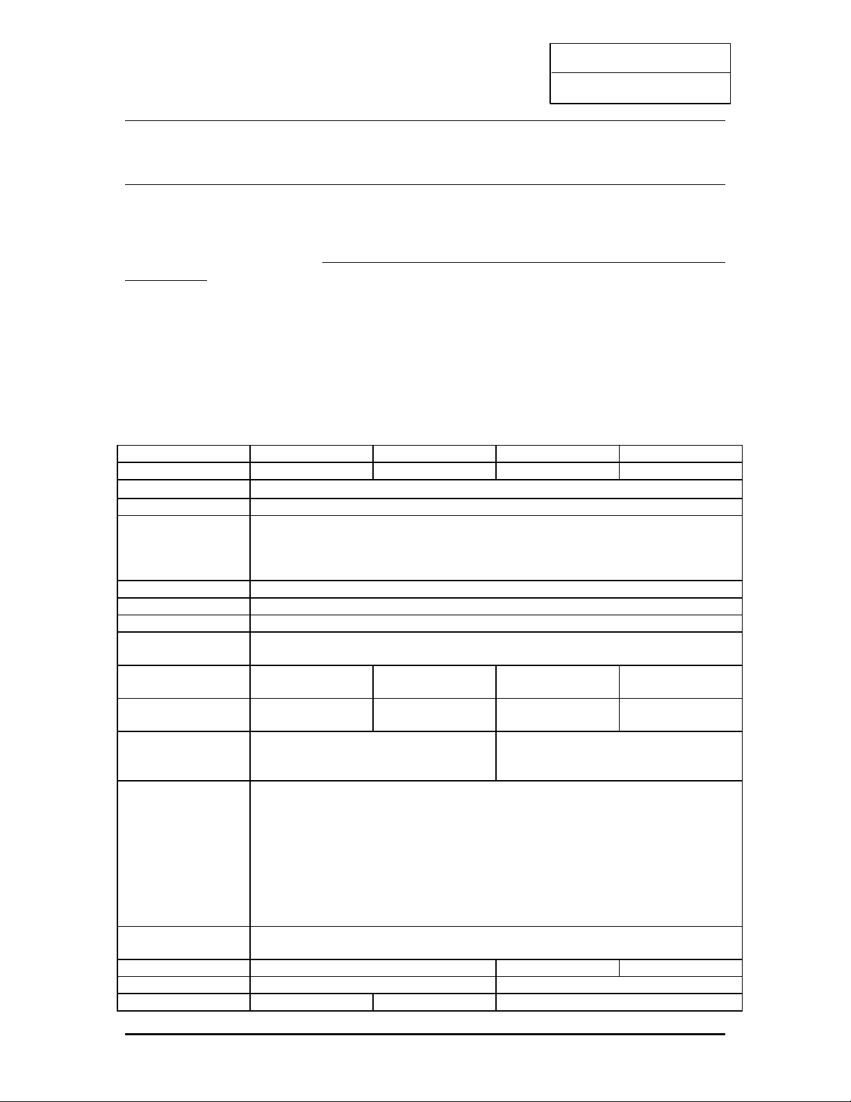
This manual applies to different models of Intel chipset mainboard. Please refer to appropriate
section and mainboard layout according to the model no.
Model No. TL-BX31 TL-ZX31 TL-BX21 TL-ZX21
Chipset i440BX i440ZX i440BX i440ZX
Socket
Slot 1
Front-Side Bus 66 / 100 MHz
Processor INTEL Pentium III 450 MHz or above Processor (Please download the updated
BIOS from our website)
INTEL Pentium II 233 – 450 MHz Processor
INTEL Celeron / Celeron A 266 MHz or above Processor
CPU Speed Jumperless setting
Voltage Regulator Built in switching voltage regulator to support 1.5V to 3.5V
Cache Built in Level 2 cache: 512KB (PII and PIII), 128KB (Celeron A)
SDRAM Support 66MHz and 100MHz (PC100) SDRAM module. Also SPD or Non SPD.
Each DIMM slot supports up to 256 MB.
168 pin DIMM
Slot
3 2 3 2
Max. System
Memory
768 MB 512 MB 768 MB 512 MB
Expansion Slots 1 x AGP 1.0 slot (1X/2X mode)
4 x PCI slots
3 x ISA slots
1 x AGP 1.0 slot (1X/2X mode)
3 x PCI slots
2 x ISA slots
On-borad I/O 2 x Ultra DMA/33 Bus Master IDE Ports (support up to 4 IDE devices and PIO
Mode 3 & 4, DMA 2 & Ultra DMA 33)
Support HD greater than 8.4GB
1 x Floppy port (up to 2.88 MB floppy)
1 x Serial ports (16550 Fast UART)
1 x Parallet port (ECP/EPP)
2 x USB ports
1 x PS/2 mouse port
1 x Infra-red port
System BIOS Award 1M or 2M Flash BIOS
Support ACPI, DMI, PnP, Green, Wake on Modem (external) features
Wake on LAN Yes -- --
Power Connector ATX ATX and AT
Sound on Board -- -- Crystal Sound (4235)
1
Page 3
INTEL PII
User’s Guide
Form Factor ATX Baby AT
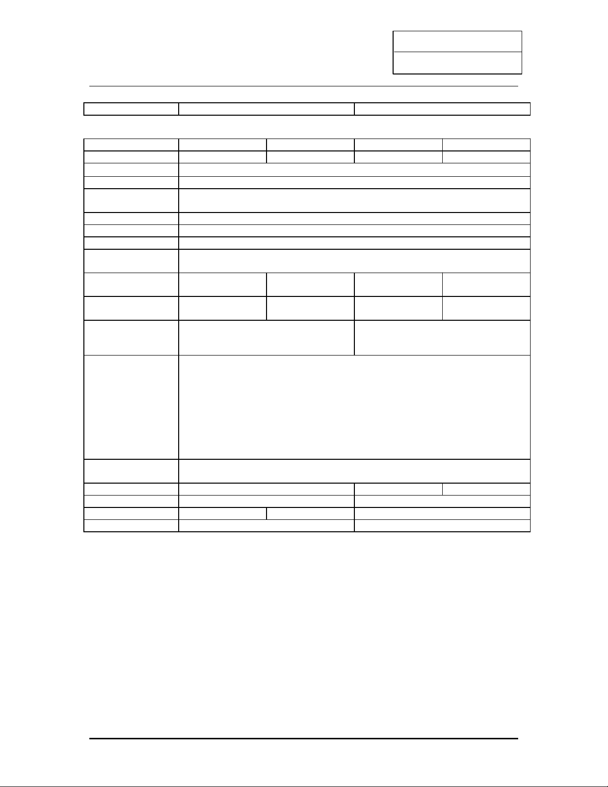
Model No. TL-IBX3-13 TL-IZX3-13 TL-IBX2-13 TL-IZX2-13
Chipset i440BX i440ZX I440BX i440ZX
Socket
Socket 370
Front-Side Bus 66 / 100 MHz
Processor INTEL Socket 370 Celeron A 300 MHz or abover Processor
CPU Speed Jumperless setting
Voltage Regulator Built in switching voltage regulator to support 1.5V to 3.5V
Cache Built in Level 2 cache: 128 KB
SDRAM Support 66MHz and 100MHz (PC100) SDRAM module. Also SPD or Non SPD.
Each DIMM slot supports up to 256 MB.
168 pin DIMM
Slot
3 2 3 2
Max. System
Memory
768 MB 512 MB 768 MB 512 MB
Expansion Slots 1 x AGP 1.0 slot (1X/2X mode)
4 x PCI slots
3 x ISA slots
1 x AGP 1.0 slot (1X/2X mode)
3 x PCI slots
2 x ISA slots
On-borad I/O 2 x Ultra DMA/33 Bus Master IDE Ports (support up to 4 IDE devices and PIO
Mode 3 & 4, DMA 2 & Ultra DMA 33)
Support HD greater than 8.4GB
1 x Floppy port (up to 2.88 MB floppy)
1 x Serial ports (16550 Fast UART)
1 x Parallet port (ECP/EPP)
2 x USB ports
1 x PS/2 mouse port
1 x Infra-red port
System BIOS Award 1M or 2M Flash BIOS
Support ACPI, DMI, PnP, Green, Wake on Modem (external) features
Wake on LAN Yes -- --
Power Connector ATX ATX and AT
Sound on Board -- -- Crystal Sound (4235)
Form Factor ATX Baby AT
Crystal (4235) Sound on Board
- Compatible with Sound Blaster, Sound Blaster Pro and Windows Sound System
- Advanced MPC3-compliant input and output mixer
- Enhanced stereo full duplex operation
- Dual Type-F DMA support
- Integrated CrystalClear 3D stereo enhancement
- Industry leading Delta-sigma data converters (90 dB DAC)
- Internal default PnP resources
- CS9236 wavetable interface
- CS4610 audio accelerator interface
2
Page 4

INTEL PII
User’s Guide
Yamaha 128 Voice SoftSynth Software
The Yamaha Software Synthesizer S-YXG50 makes it possible for computers with MMX
technology to playback MIDI data with higher sound quality than ever. Even to CD quality level
without using hardware. As it also supports DirectSound as well, you can also enjoy the sound
effects from the latest DirectSound multimedia games.
Yamaha XG Studio Mixer
This versatile playback software allows you to play MIDI files in tandem with animation, video
and still images to create a wonderful multimedia effect. In addition, it allows you to change all
aspects of the MIDI files from its tempo, volume, source, special effects, voice and individual
instruments; so that you are in complete control of the sound effects.
1.2 CHECKLIST
Mainboard x 1
User’s Guide x 1
CD Driver x 1
FDD & HDD Cable Pack (Sound connector card & ATX form card for Baby AT mainboard
only)
1.3 STATIC ELECTRICITY PRECAUTIONS
Static electricity can easily damage your mainboard. Following procedures can help you to
protect your mainboard from electrostatic discharge :
- Keep the mainboard and other system components in their anti-static packaging until you are
ready to install them.
- Ground yourself before removing any system component from its protective anti-static
packaging. A grounded surface within easy reach is the expansion slot covers at the rear of the
system case or any other unpainted portion of the system chassis.
- Frequently ground yourself to discharge any static electric charge that may build up in your
body while working on installation and/or configuration.
- Handle the mainboard by its edges or by the mounting bracket to avoid touching its
components.
3
Page 5
INTEL PII
User’s Guide
2. HARDWARE CONFIGURATION
Before you install the mainboard into the system chassis, you may find it convenient to
first configure the mainboard’s hardware. This chapter describes how to set jumpers and
install memory modules, and where to attach components.
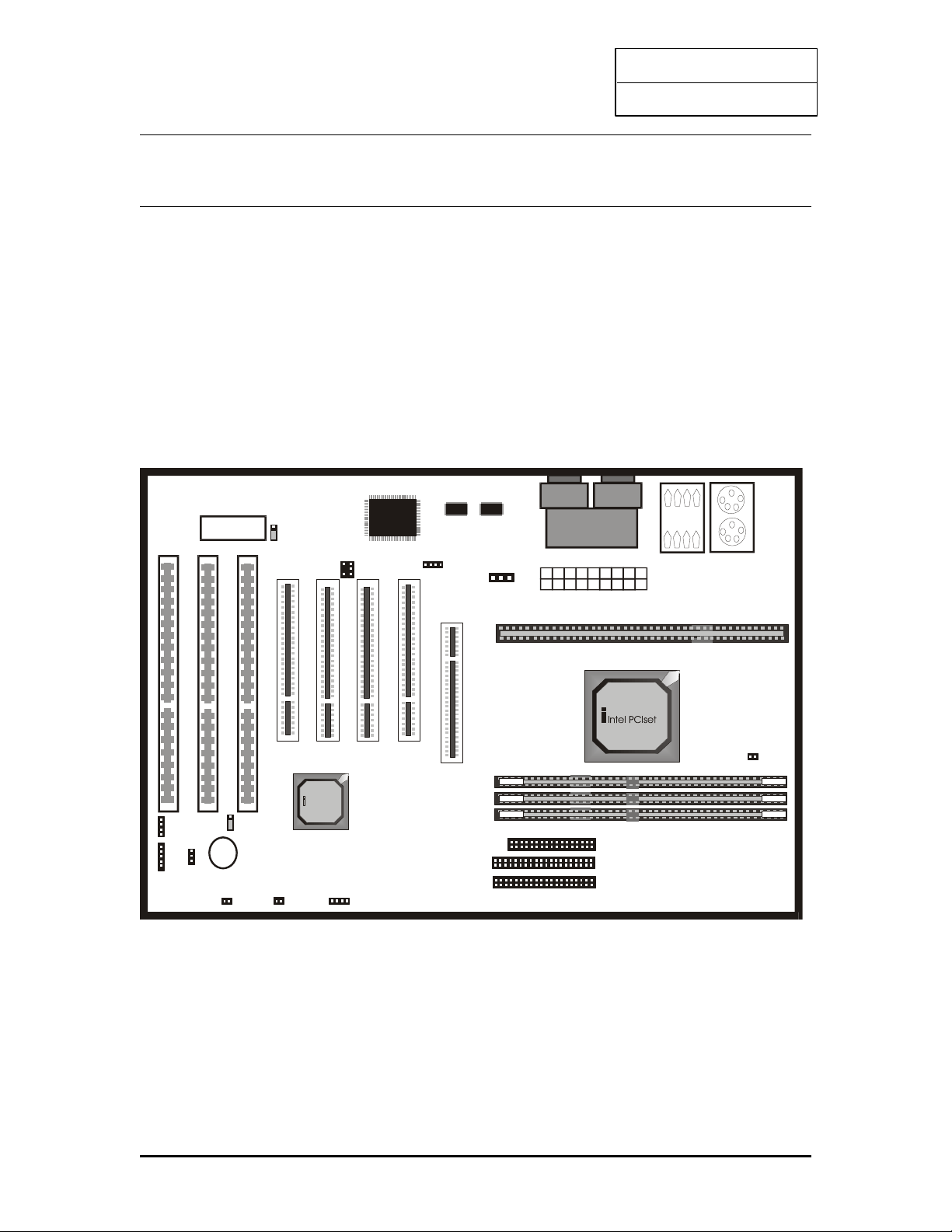
**You can find the Model No. label on the mainboard.**
2.1 MAINBOARD LAYOUT
Model No: TL-BX31
USB 0 /1
C O M 1 C O M2
LPT1
Inte l PC Iset
RTC
1
Speaker
1
PWR+
KEYLOCK
P1
J23
P6
RESET Power Button
P2
HD-LED
P5
JP11
“Normal”
DIMM0
DIMM1
J26 ATX POWER CONNECTOR
A G P S L O T
SLO T 1
LO WER:
PS2
KEYBOARD
UPPER:
PS2 MO USE
J7
J8
IDE1
IDE2
1
1
Floppy
J1
1
P9
BIOS
J25
1
1 2
J27
J21
P4
+
1
P11
DIMM2
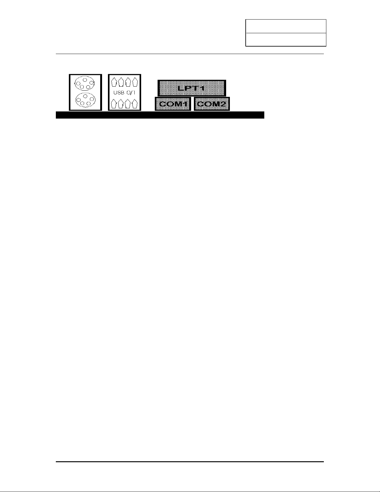
ATX On board Connector Description
PS/2 Mouse USB Port 1 Printer Port
4
Page 6
INTEL PII
User’s Guide
PS/2 Keyboard USB Port 2 Serial Port 1 / 2
5
Page 7
INTEL PII
User’s Guide
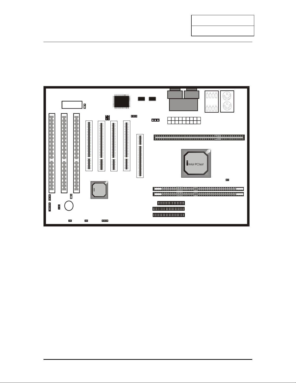
Model No: TL-ZX31
USB 0/ 1
C O M1 C O M2
LPT1
Inte l PC Iset
RTC
1
Speaker
1
PWR+
KEYLOCK
P1
J23
P6
RESET Power Button
P2
HD-LED
P5
JP11
“Normal”
DIMM0
DIMM1
J26 ATX POWER CONNECTOR
A G P S L O T
SLO T 1
LO WER:
PS2
KEYBOARD
UPPER:
PS2 MO USE
J7
J8
IDE1
IDE2
1
1
Floppy
J1
1
P9
BIOS
J25
1
1 2
J27
J21
P4
+
1
P11
6
Page 8
INTEL PII
User’s Guide
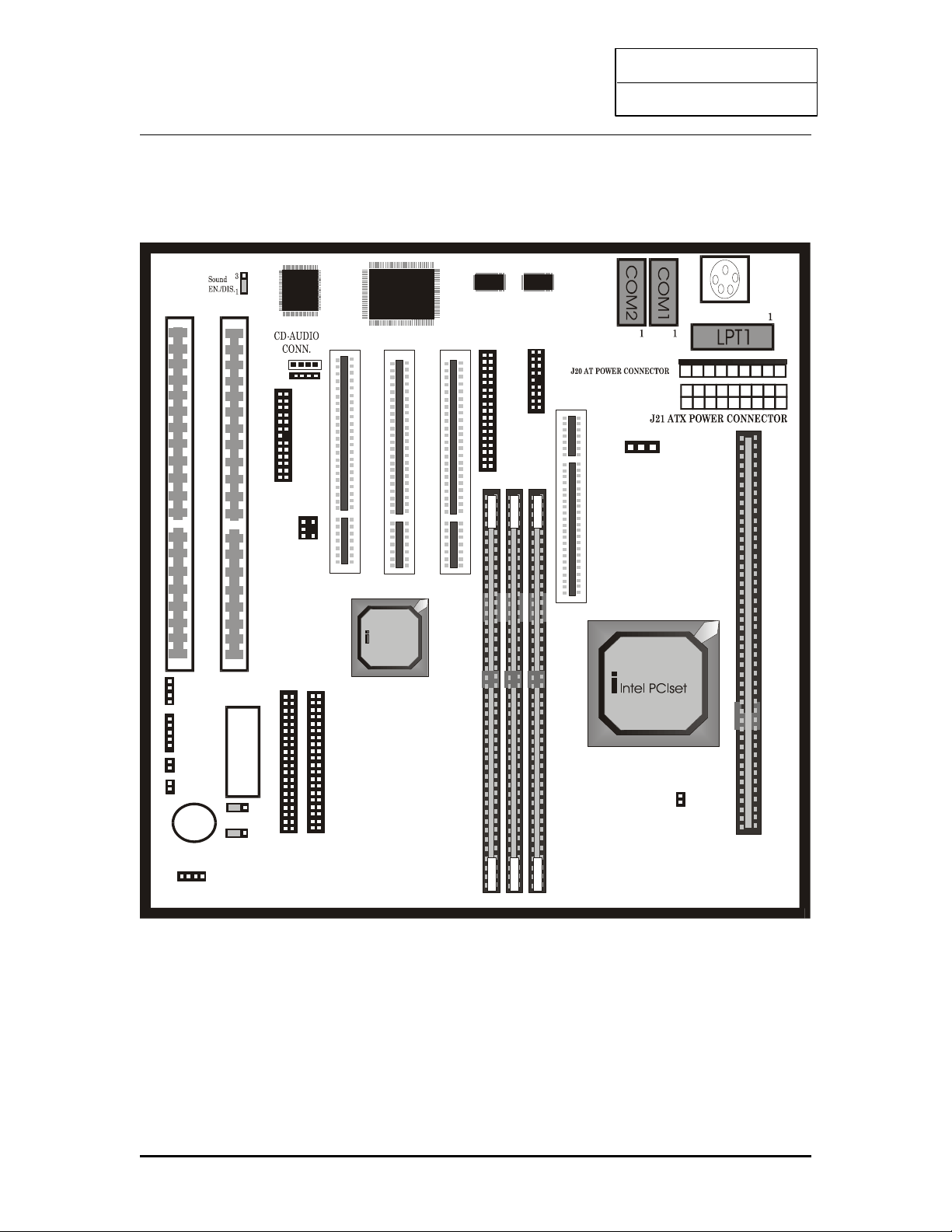
Model No.: TL-BX21
Intel PC Iset
RTC
1
Speaker
1
P1
J23
P6
P2
HD-LED
P5
JP11
“Normal”
AGP SLOT
SLOT 1
1
BIOS
J25
1
2 1
J27
P4
+
J32
J31
IDE1
IDE2
1 1
J30
Jp13
Floppy
1
ATX-From card
J28
P11
+ +
7
Page 9
INTEL PII
User’s Guide
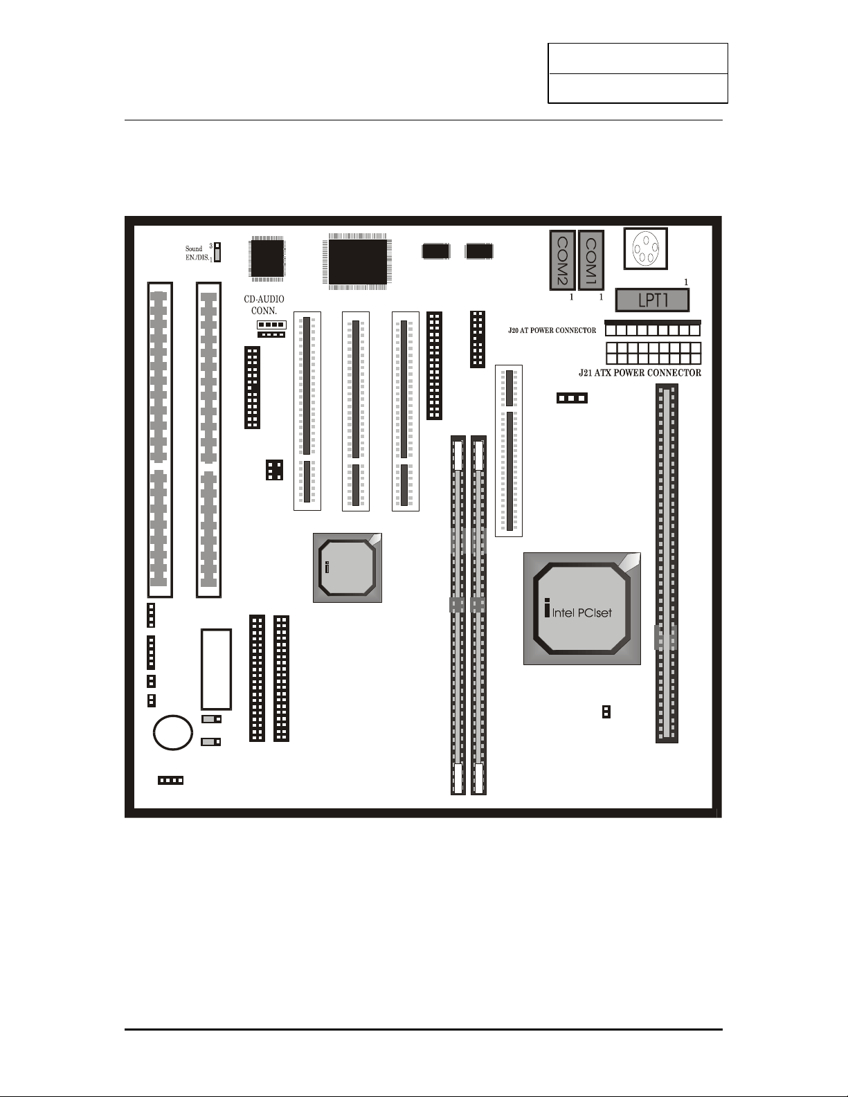
Model No.: TL-ZX21
Intel PC Iset
RTC
1
Speaker
1
P1
J23
P6
P2
HD-LED
P5
JP11
“Normal”
AGP SLOT
SLOT 1
1
BIOS
J25
1
2 1
J27
P4
+
J32
J31
IDE1
IDE2
1 1
J30
Jp13
Floppy
1
ATX-From card
J28
P11
+ +
8
Page 10
INTEL PII
User’s Guide
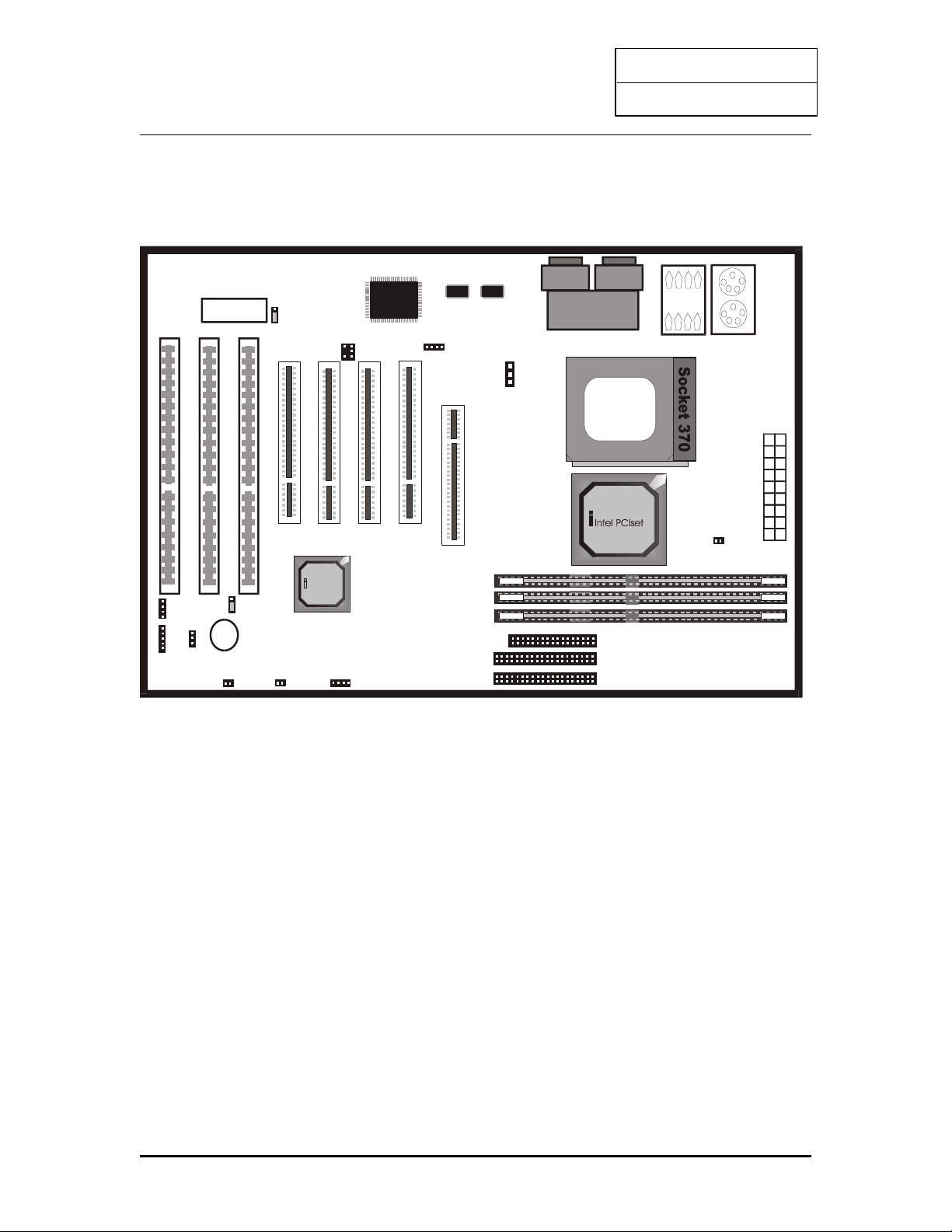
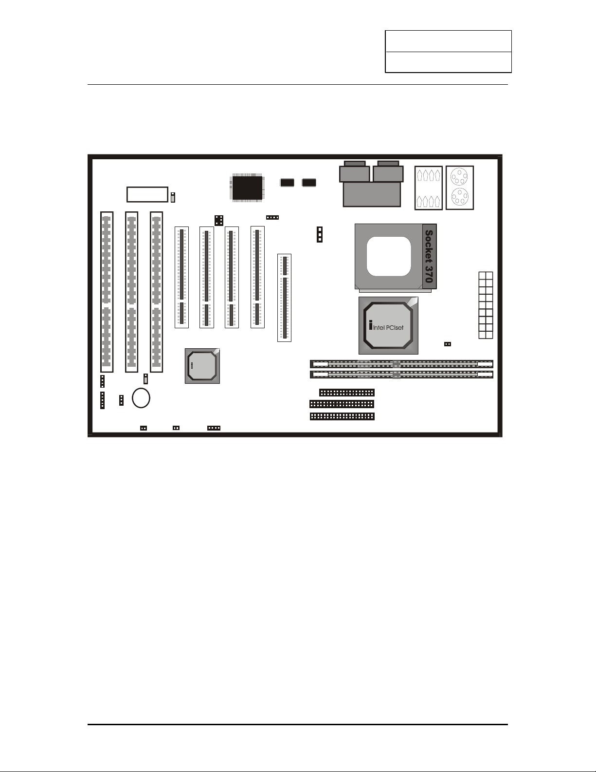
Model No.: TL-IBX3-13
USB 0/ 1
C O M1 C O M2
LPT1
Intel PCIset
RTC
1
Speaker
1
PWR+
KEYLOCK
P1
J23
P6
RESET Power Button
P2
HD-LED
P5
JP11
“Normal”
DIMM0
DIMM1
J26 ATX POWER CONNECTOR
AG P SLO T
LOWER:
PS2
KEYBOARD
UPPER:
PS2 M O USE
J7
J8
IDE1
IDE2
1
1
Floppy
J1
1
P9
BIOS
J25
1
1 2
J27
J21
P4
+
1
SLO T 1
1
DIMM2
P11
9
Page 11
INTEL PII
User’s Guide
Model No.: TL-IZX3-13
USB 0/ 1
C O M1 C O M2
LPT1
Inte l PCIset
RTC
1
Speaker
1
PWR+
KEYLOCK
P1
J23
P6
RESET Power Button
P2
HD-LED
P5
JP11
“Normal”
DIMM0
DIMM1
J26 ATX POWER CONNECTOR
AG P SLO T
LO WER:
PS2
KEYBOARD
UPPER:
PS2 MO USE
J7
J8
IDE1
IDE2
1
1
Floppy
J1
1
P9
BIOS
J25
1
1 2
J27
J21
P4
+
1
SLO T 1
1
P11
10
Page 12
INTEL PII
User’s Guide
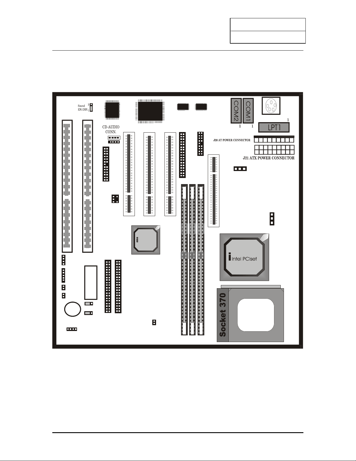
Model No.: TL-IBX2-13
Intel PC Iset
RTC
1
Speaker
1
P1
J23
P6
P2
HD-LED
P5
JP11
“Normal”
AGP SLOT
1
BIOS
J25
1
2 1
J27
P4
+
J32
J31
IDE1
IDE2
1 1
J30
Jp13
Floppy
1
ATX-From card
J28
P11
+ +
P12
SLO T 1
1
11
Page 13
INTEL PII
User’s Guide
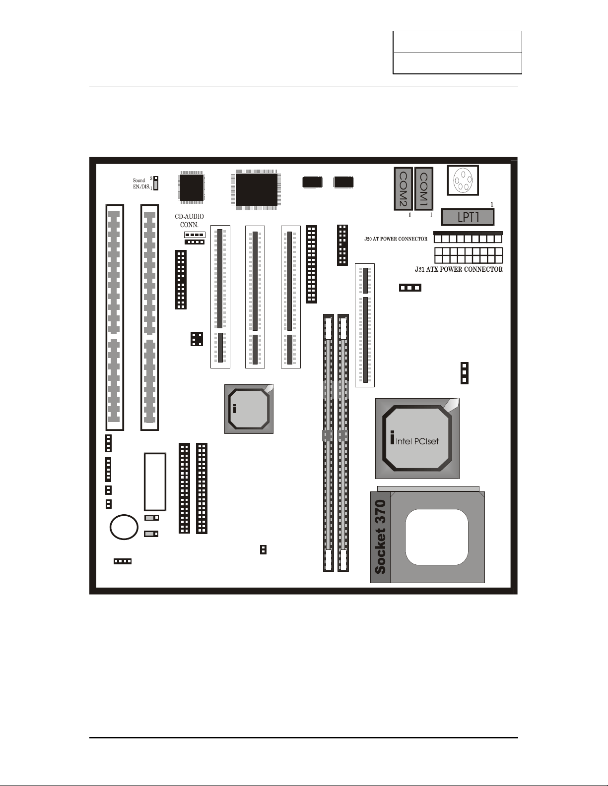
Model No.: TL-IZX2-13
Intel PC Iset
RTC
1
Speaker
1
P1
J23
P6
P2
HD-LED
P5
JP11
“Normal”
AGP SLOT
1
BIOS
J25
1
2 1
J27
P4
+
J32
J31
IDE1
IDE2
1 1
J30
Jp13
Floppy
1
ATX-From card
J28
P11
+ +
P12
SLO T 1
1
12
Page 14
INTEL PII
User’s Guide
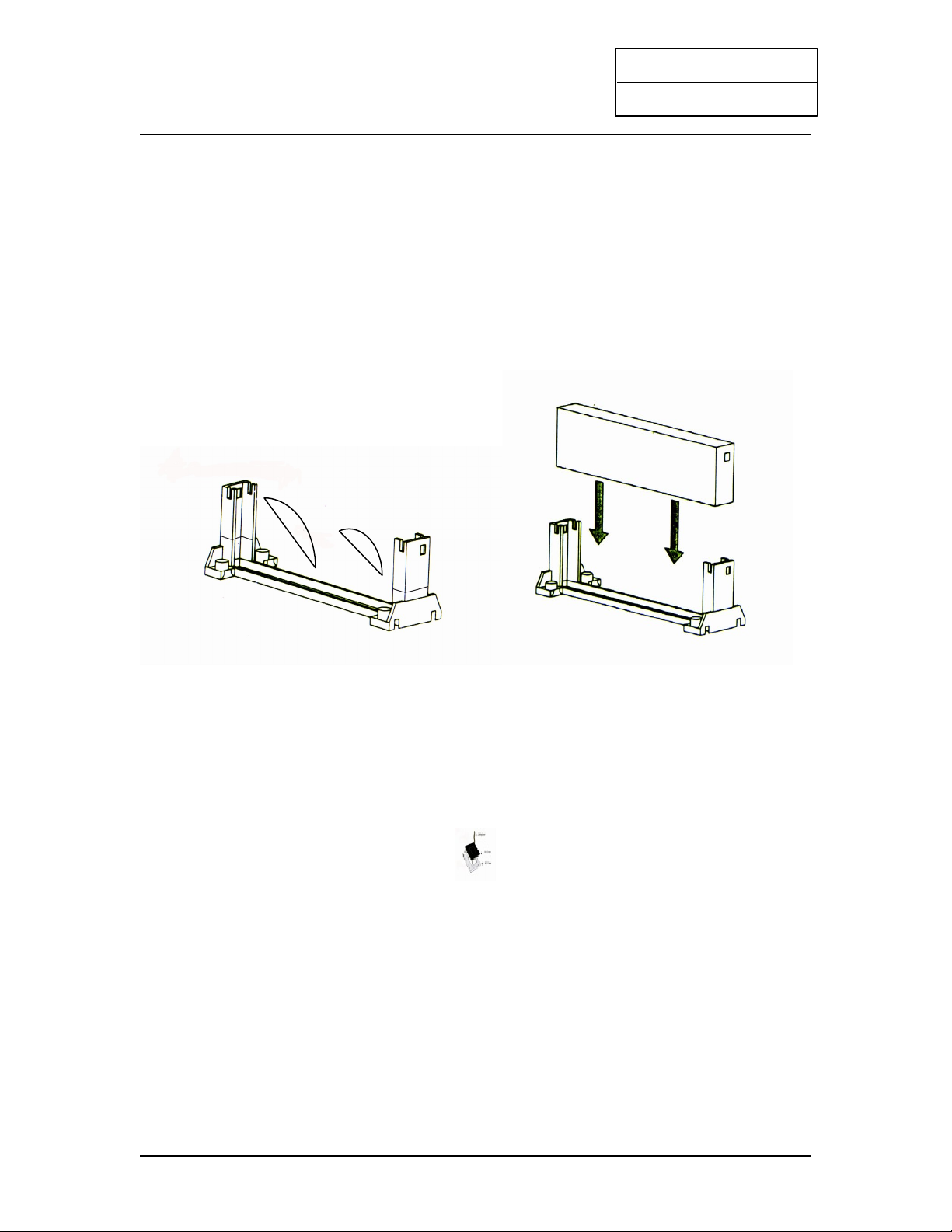
2.2 INSTALLING CPU
This mainboard supports the Pentium II CPU using Single Edge Contact (SEC) slot and Socket 370.
Slot 1
To install the CPU, flatten the two latches on the side of the CPU, insert the CPU into the
retention clip. Lock the two latches to secure the CPU. Insert the clip portion of the CPU
supporter so that the heat sink can sit on top of the whole CPU supporter.
Socket 370
Match pin 1 of the CPU with pin 1 of the CPU socket. The pin 1 corner of the CPU socket is
designated by a small triangle printed on the motherboard. Carefully insert the CPU into the
CPU socket and move the metal arm downward to replace it in its original position.
13
Page 15

INTEL PII
User’s Guide
2.3 HOW TO SET JUMPER
Jumper switch is used to select between various operating modes. A jumper switch consists of
two or three gold pins, which stretches out from the system board. By using the cap to cover two
pins is to short those pins. If the cap is not placed on any pins at all, it indicates to leave the pins
open.
To set a jumper switch, please refer to below :
¨ to close a jumper, insert the plastic jumper cap over two pins of a jumper
¨ to open a jumper, remove the jumper cap
The following conventions are used to represent the proper jumper settings :
OPEN
3 1 3 1
CLOSED (2-3 position)
3 1 3 1
NOTE : When you open a jumper, attach the plastic jumper cap to one of the pins so you
won’t lose it.
2.4JUMPERS & CONNECTORS
Setting the CPU Voltage
This mainboard supports Pentium II VID function, the CPU core voltage is automatically
detected, the range is from 1.3V to 3.5V.
Pentium II VID signal provides CPU voltage auto-detection, therefore, no worries on
wrong CPU voltage select.
14
Page 16
INTEL PII
User’s Guide
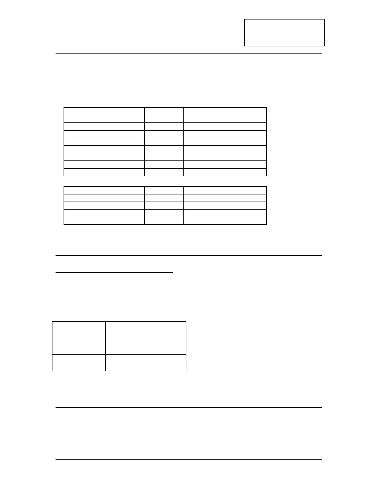
Selecting the CPU Frequency
The possible settings of current CPU available on the market are listed below, and pls
verify the BIOS – “CPU SPEED SETTING” to set the correct CPU Clock+Ratio.
Pentium II / Celeron A CLock Ratio
233MHz 66MHz 3.5
266MHz 66MHz 4
300Mhz 66MHz 4.5
333MHz 66MHz 5
366MHz 66MHz 5.5
400MHz 66MHz 6
433MHz 66MHZ 6.5
466MHz 66MHZ 7
Pentium II / III CLock Ratio
350MHz 100MHz 3.5
400MHz 100MHz 4
450MHz 100MHZ 4.5
500MHz 100MHZ 5
FOR INTERNAL TEST ONLY
F.S.B 66 / 100 MHz Selector (Pin 11)
Pin 11 Description
Open 100 Mhz
Close 66 / 100 Mhz
Note: The mainboard chipset supports maximum 100 Mhz frequency, the over 100
Mhz settings are for internal test only, which may cause serious system damage
15
Page 17

INTEL PII
User’s Guide
2.4.1 ATX Mainboard
CPU FAN connector (P4)
Plug in the fan cable to the 3-pin fan connector onboard. The fan connector is marked CPU
FAN and FAN on the system board.
Pin1 Sense
Pin2 +12V
Pin3 GND
Flash ROM Voltage Selector (J25)
Pin Description
1-2
2-3
12v (default)
5v
Note : The factory default is 1-2, it is not recommended to change the factory default setting.
ATX Soft-Power Switch Connector (P2)
The ATX soft-power switch connector is a 2 pin header on the system board. Locate the
power switch cable from your ATX housing. Plug this connector to the soft-power switch
connector marked P2 PWRBT.
P2 PWERBT function
Post ON Instant ON/OFF
Post OFF Delay 4 second
16
Page 18
INTEL PII
User’s Guide
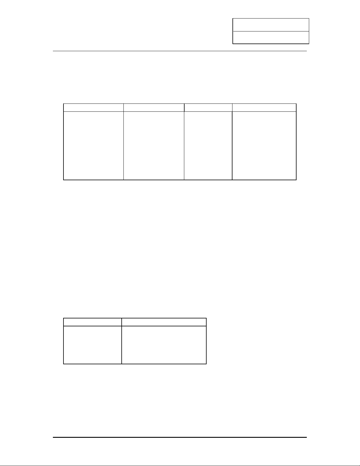
ATX power connector pinout
The ATX power supply provides a single 20-pin connector.
Pin Description Pin Description
1
2
3
4
5
6
7
8
9
10
3.3V
3.3V
Ground
+5V
Ground
+5V
Ground
Power OK
5VSB
+12V
11
12
13
14
15
16
17
18
19
20
3.3V
-12V
Ground
PS-ON
Ground
Ground
Ground
-5V
+5V
+5V
Note: Some ATX-Power does not have –5V voltage output, it will effect some functional of
ADD-ON card device.
Software Power-Off
Following the steps below to use the “Software Power-Off control” function in windows
95 with ATX power supply.
1.Click the START button on the Windows 95 task bar.
2.Select Shut Down The computer to turn off the system. It is now safe to turn off your
computer.” will not be shown when using this function.
Power Led and Keylock Connector (J23)
Keylock connector enables and disables the keyboard key-in function on the case.
Pin Description
1
2
3
4
5
LED Output
N.C
Ground
Keylock
Ground
17
Page 19

INTEL PII
User’s Guide
Infra Red Connector (J21)
Pin Description
1
2
3
4
VCC
IRRX
Ground
IRTX
SB-Link (J27)
SB-Link is a connector used especially with a Creative PCI sound card. The SB-link guides
signals from the ISA bus to the PCI sound card through a cable which comes with the PCI
sound card. This is necessary because some DOS based games address the ISA bus directly.
Speaker Connector (P1)
Pin Description
1
2
3
4
Data Out
N.C
Ground
+5V
Hard-Disk Active LED (P5)
Pin Description
1
2
3
4
Active signal
Ground
Ground
Active signal
Reset Switch Connector (P6)
Attach the Reset push cable to this connector
Setting Description
Open
Close
Normal Mode
Reset System
18
Page 20
INTEL PII
User’s Guide
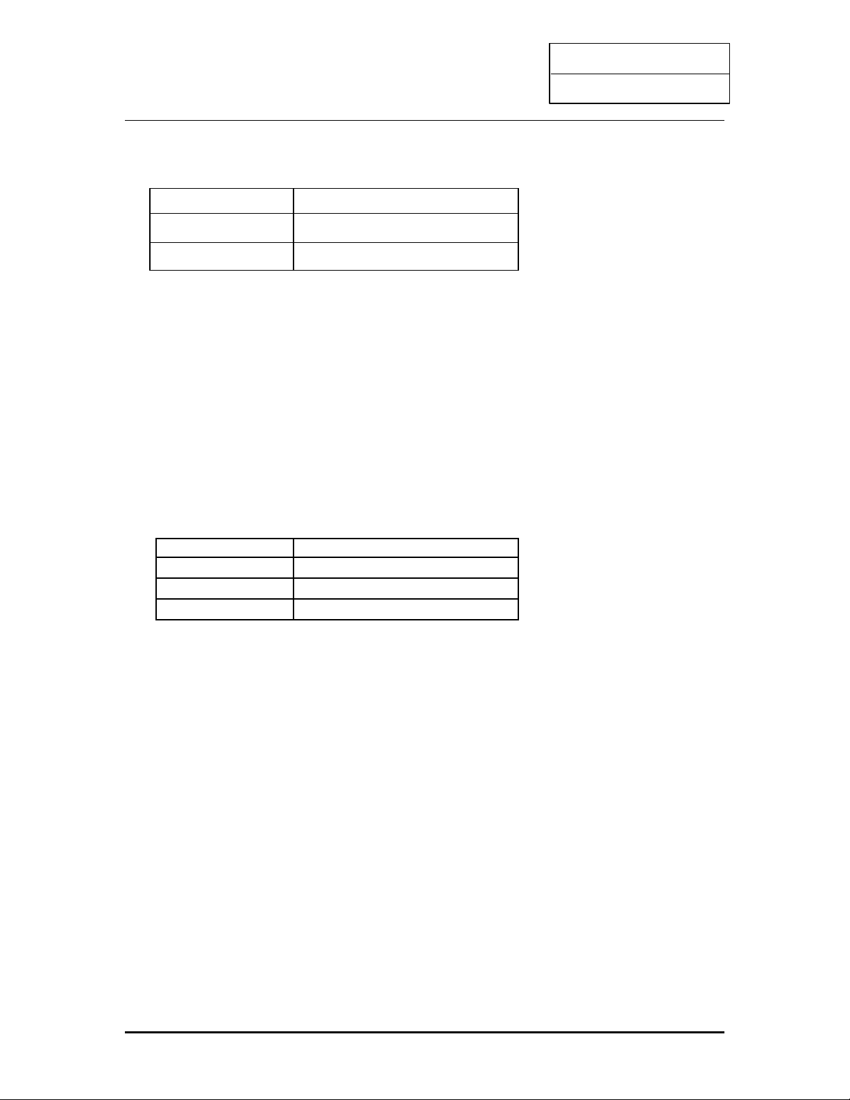
CMOS state (JP11)
JP11 CMOS Setting
1-2 Normal operation
2-3 Clear CMOS
Wake-on-LAN Connector (P9)
The Wake-on-LAN connector powers up the system when a wakeup packet or signal is received from
the network tthrough the INTEL L101 LAN card:
INPORTANT: This feature requires that the Wake-on-LAN Power up control BIOS is set to Enabled
and that your system has an ATX power supply with +5V standby power.
WAKE-LAN(P9)
Pin Description
1 +5V Standby
2 GND
3 NC
What is Wake-on-LAN?
The Wake-on-LAN feature provides the capability to remotely power on systems supporting
Wake-on-LAN by simply sending a wake-up frame. With this feature, remotely
uploading/downloading data to/from systems during off-peak hours will be feasible.
Wake-on-LAN is a remote management tool with advantages that can reduce system
management workload, provide flexibility to the system administrator’s job, and then of course
save your time-consuming efforts and costs.
To enable Wake—on-LAN function, your system requires Ethernet LAN adapter card that can activate
Wake-on—LAN function, a client with Wake-on-LAN capability, and software such as LDCM rev3.10 or
up that can trigger wake-up frame.
19
Page 21
INTEL PII
User’s Guide
2.4.2 Baby AT Mainboard
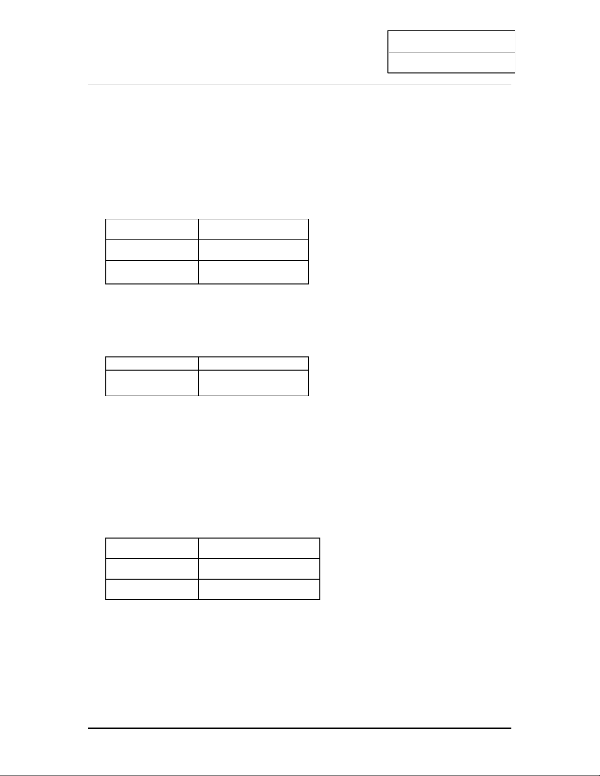
CPU FAN connector (P4)
Plug in the fan cable to the 3-pin fan connector onboard. The fan connector is marked CPU
FAN and FAN on the system board.
Pin1 Sense
Pin2 +12V
Pin3 GND
Flash ROM Voltage Selector (J25)
Pin Description
1-2
2-3
12v (default)
5v
Note : The factory default is 1-2, it is not recommended to change the factory default setting.
ATX Soft-Power Switch Connector (P2)
The ATX soft-power switch connector is a 2 pin header on the system board. Locate the
power switch cable from your ATX housing. Plug this connector to the soft-power switch
connector marked P2 PWRBT.
P2 PWERBT function
Post ON Instant ON/OFF
Post OFF Delay 4 second
20
Page 22
INTEL PII
User’s Guide
Power Led and Keylock Connector (J23)
Keylock connector enables and disables the keyboard key-in function on the case.
Pin Description
1
2
3
4
5
LED Output
N.C
Ground
Keylock
Ground
ATX power connector pinout (J21)
The ATX power supply provides a single 20-pin connector.
Pin Description Pin Description
1
2
3
4
5
6
7
8
9
10
3.3V
3.3V
Ground
+5V
Ground
+5V
Ground
Power OK
5VSB
+12V
11
12
13
14
15
16
17
18
19
20
3.3V
-12V
Ground
PS-ON
Ground
Ground
Ground
-5V
+5V
+5V
Note: Some ATX-Power does not have –5V voltage output, it will effect some functional of
ADD-ON card device.
Software Power-Off
Following the steps below to use the “Software Power-Off control” function in windows
95 with ATX power supply.
1.Click the START button on the Windows 95 task bar.
2.Select Shut Down The computer to turn off the system. It is now safe to turn off your
computer.” will not be shown when using this function.
AT power connector pinout (J20)
21
Page 23
INTEL PII
User’s Guide
The AT power supply provides a single 12-pin connector.
Pin Description
1
2
3
4
5
6
7
8
9
10
11
12
+5V
+5V
+5V
-5V
Ground
Ground
Ground
Ground
-12V
+12V
+5V
Power Good
Speaker Connector (P1)
Pin Description
1
2
3
4
Data Out
N.C
Ground
+5V
Hard-Disk Active LED (P5)
Pin Description
1
2
3
4
Active signal
Ground
Ground
Active signal
Reset Switch Connector (P6)
Attach the Reset push cable to this connector
Setting Description
Open
Close
Normal Mode
Reset System
CMOS state (JP11)
22
Page 24
INTEL PII
User’s Guide
JP10 CMOS Setting
2-3 Normal operation
1-2 Clear CMOS
Onboard Sound Enable/Disable (JP13)
JP13 Description
1-2
2-3
Enable
Disable
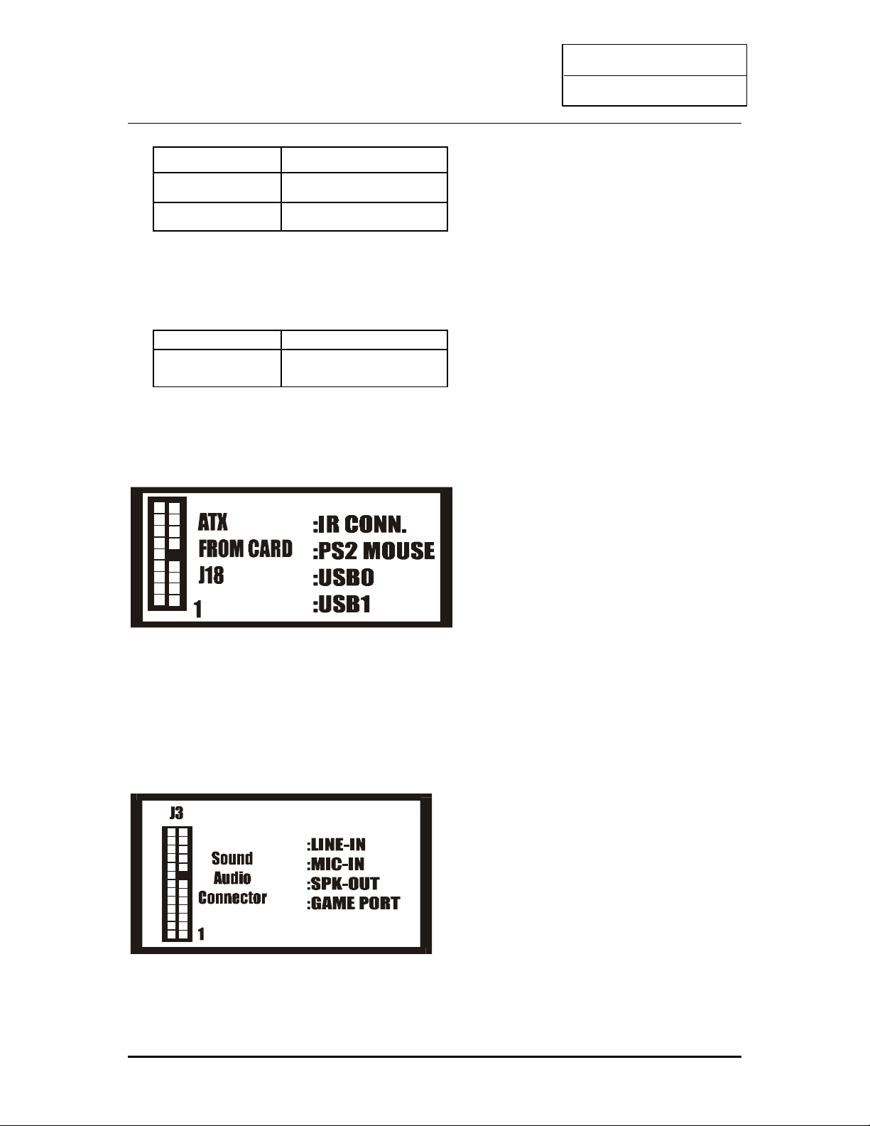
On board Connector Description
ATX From Card – J28
On Board Audio Connector – J30
23
Page 25

INTEL PII
User’s Guide
CD Audio Connector – J32, J31
Connect to “Audio” on the CD-ROM drive, and the signal for Panasonic jack is G-S-G-S and SG-G-S for Sony.
2.5 Memory Configuration
The DIMM types supported are EDO and SDRAM. This mainboard has two or three 168 pin DIMM
socket that allow you to install system memory up to 512MB or 768MB.
In 100 MHz system, SPD SDRAM and PC100 specification SDRAM is recommended.
Serial Presence Detect (SPD)
-1 Specification:
-SDRAMS: SDRAM SPD specification Rev 1.1 or later
-2 SPD usage and 100MHz Systems:
-MUST use SPD method to detect/size memory.
-If BIOS detects non-SPD DIMMS (or SPD data is invalid) in a system, then BIOS
should “BEEP” and stop executing POST. –“depends on the factory BIOS setting”
-3 What happens if non-SPD DIMMS are used in 100MHz system:
-BIOS cannot verify if the DIMMS used, meet 100MHz requirment.
-Memory access without programming Buffer strengths FIRST, may return incorrect
data and/or damage the momory
-Incorrect Buffer strength programming for REG. SDRAM.
-CAS# Latency, RAS#-CAS# delay and RAS# Precharge bits will need to be
programmed to lowest performance values
-BIOS cannot distinguish between 2&4 bank 64MB SDRAMS.
24
Page 26
INTEL PII
User’s Guide
3. AWARD BIOS SETUP
Enter the Award Setup program's Main Menu as follows:
1. Turn on or reboot the system. The following message appears at the bottom of the
screen:
"Press <DEL> to enter setup, ESC to skip memory test"
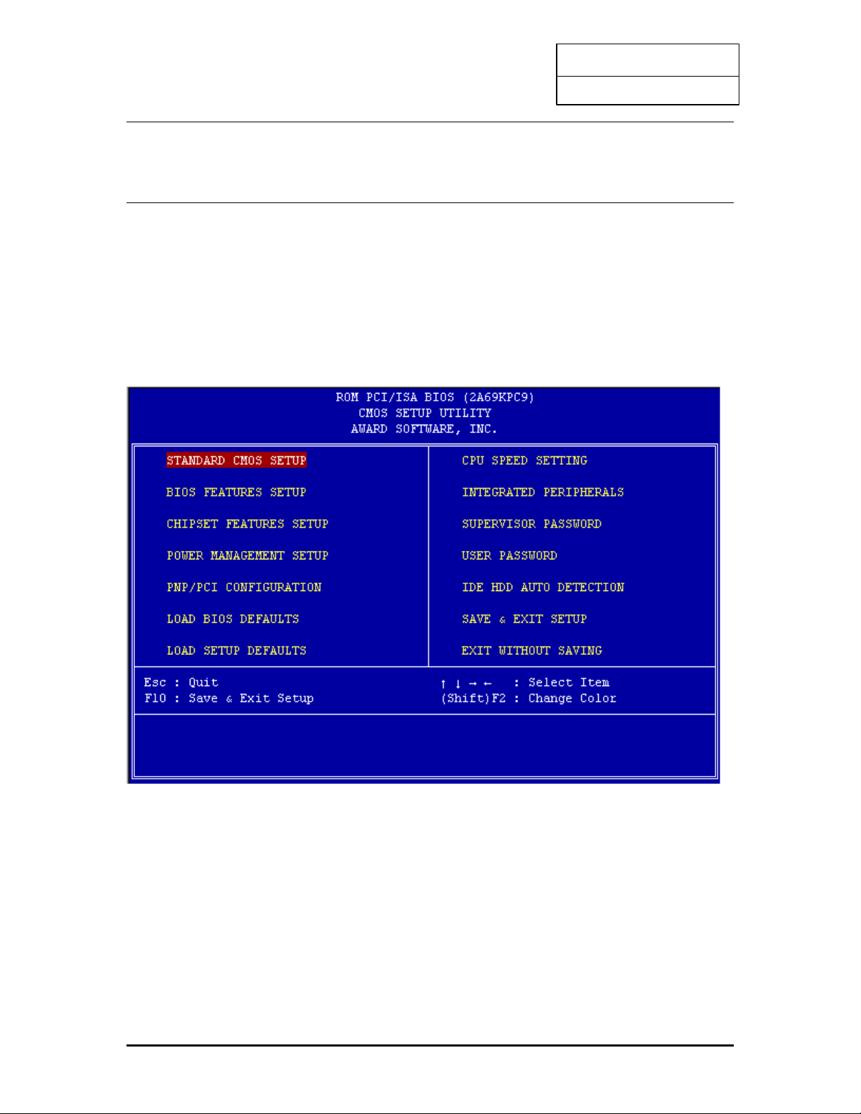
2. Press the <DEL> key to enter the Award BIOS setup program and the following screen
appears:
3. Choose an option and press <Enter>. Modify the system parameters to reflect the
options installed in the system. (See the following sections for more information.)
4. Press <Esc> at anytime to return to the Main Menu.
5. In the Main Menu, choose "SAVE AND EXIT SETUP" or <F10> to save your changes
and reboot the system.
Choosing "EXIT WITHOUT SAVING" or <Esc> ignores your changes and exits the
program.
24
Page 27
INTEL PII
User’s Guide
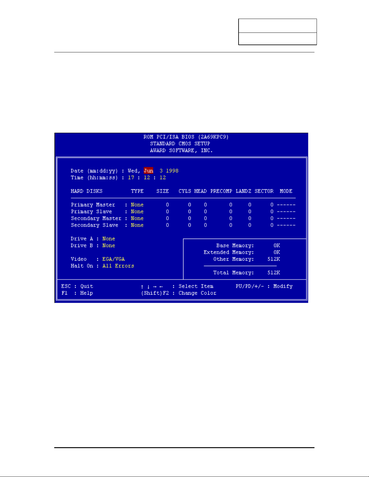
3.1 STANDARD CMOS SETUP
Run the Standard CMOS Setup as follows.
1. Choose "STANDARD CMOS SETUP" from the Main Menu and a screen with a list of
items appears.
2. Use the arrow keys to move between items and to select values. Modify the selected
fields using PgUp/PgDn/+/-keys. Some fields let you enter numeric values directly.
Data (mm/dd/yy) Type the current date
Time (hh:mm:ss) Type the current time
25
Page 28

INTEL PII
User’s Guide
Primary / Secondary master and slave
Choose from the standard hard disk types 1 to 46, or "User" defined. If you choose "User", run
the IDE HDD Auto detection function from the Main Menu, or enter the HDD information
directly from the keyboard and press <Enter>. If you use Auto mode the BIOS can Auto detect
HDD type and do not need to enter any HDD information from the keyboard.
Drive A & B
Choose 360KB 5 1/4" , 1.2MB 5 1/4", 720MB 3 1/2", 1.44MB 3 1/2", Not installed
Video
Choose Monochrome, Color 40x25, VGA/EGA, Color 80x25
Halt On
Choose All Errors (Default), No Errors, All, But Keyboard; All, But Diskette; All,
But Disk/Key
3. After you have finished with the Standard CMOS Setup program, press the <ESC> key
to return to the Main Menu.
26
Page 29
INTEL PII
User’s Guide
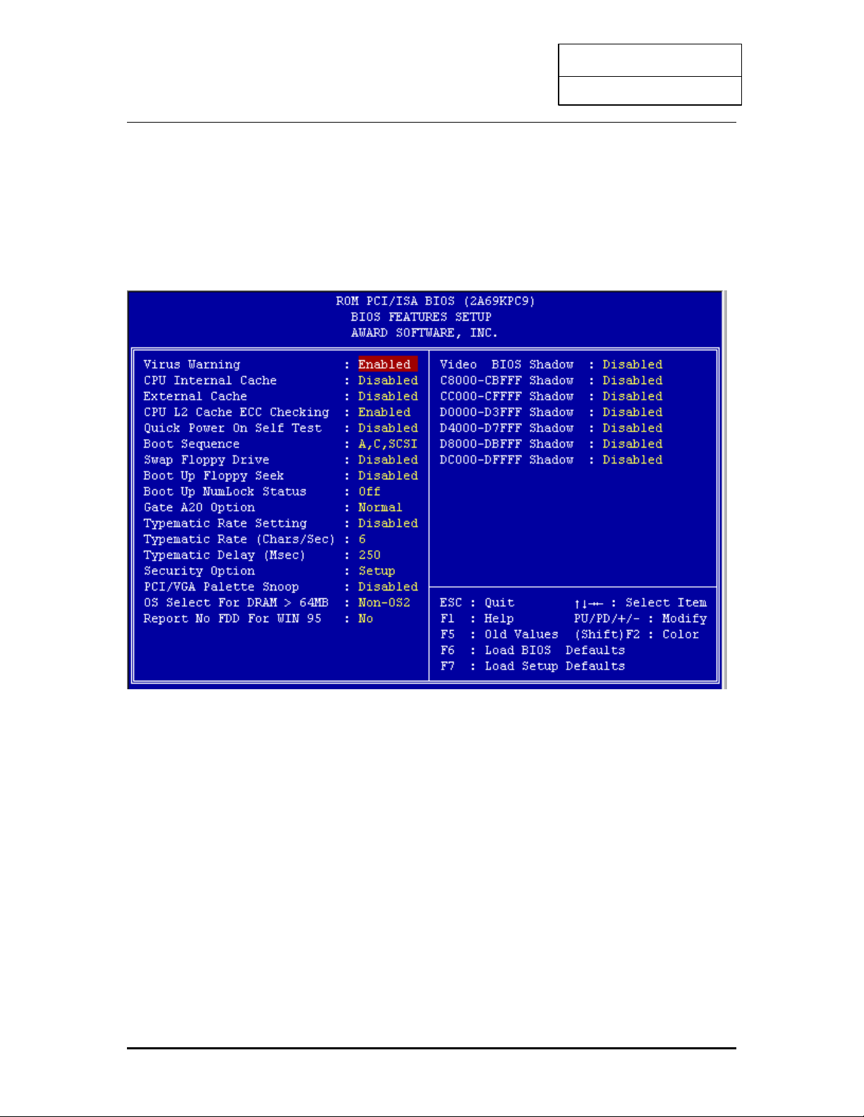
3.2 BIOS FEATURES SETUP
Run the BIOS Features Setup as follows.
1. Choose "BIOS FEATURES SETUP" from the Main Menu and a screen with a list of
items appears.
2 Use the arrow keys to move between items and to select values. Modify the selected
fields using the PgUp/PgDn/+/-Keys. An explanation of <F> keys follows:
<F1>: "Help" gives options available for each item.
<F2>: Change color
<F5>: Get the old values. The user started the current session with these
values.
<F6>: Load all options in the BIOS Features Setup with the BIOS Default
values.
<F7>: Load all options in the BIOS Features Setup with the Setup Default
values.
27
Page 30

INTEL PII
User’s Guide
A short description of the screen items follows:
Virus Warning
Choose Enabled or Disabled. Enable this option and a SYSTEM WARNING MESSAGE
appears when the system detects a virus.
CPU Internal Cache
Choose Enabled or Disabled. This option lets you enable the CPU's Cache internal cache
Choose “Enable”.
External Cache
Choose Enabled or Disabled. This option lets you enable the external cache memory. For better
performance, make sure you always choose "Enabled."
CPU L2 Cache ECC Checking
This function controls the ECC check capability in the CPU level 2 cache.
Quick Power On
Choose Enabled or Disabled. Enabled provides a fast POST and boot-Self Test up speed.
Boot Sequence
This field determines where the system looks first for an operating system. Options are C,A;
A,CDROM,C; CDROM,C,A; D,A; E,A; F,A; LS/ZIP, C and A,C
Swap Floppy Drive
Choose Enabled or Disabled. When Enabled Floppy drives A & B are swapped under DOS.
Boot Up Floppy Seek
Choose Enabled or Disabled. "Disabled" provides a fast boot and reduces the possibility of
damage to the heads.
Boot Up Num Status
Choose On or Off. On puts numeric keypad in Num Lock mode at Lock Status boot-up. Off
puts this keypad in arrow key mode at boot-up.
Boot Up System
Choose High or Low. This option lets you choose system bootup Speed speed. The default is
High.
Gate A20 Option
28
Page 31

INTEL PII
User’s Guide
Choose Fast or Normal. This item lets you use the GA20 from the chipset or the keyboard
controller.
Typematic Rate Setting
Choose Enabled or Disabled. Enable this option to adjust the keystroke repeat rate.
Typematic Rate (chars/sec)
Choose the rate a character keeps repeating.
Typematic Delay (Msec.)
Choose how long after you press a key that a character begins repeating.
Security Option
Choose Setup, or System. Use this feature to prevent unauthorized system boot-up or
unauthorized use of BIOS Setup.
"System" - Each time the system boots the password prompt appears
"Setup" - Password prompt only appears if you attempt to enter the Setup program.
Video BIOS VIDEO shadow
Copies BIOS code from slower ROM to faster RAM. Shadow BIOS can then execute from
RAM.
Report No FDD For WIN95
Select “NO” will bypass all FDD access in WIN95 system.
3. After you have finished with the BIOS Features Setup program, press the <ESC> key
and then follow screen instructions to save or disregard your settings.
29
Page 32
INTEL PII
User’s Guide
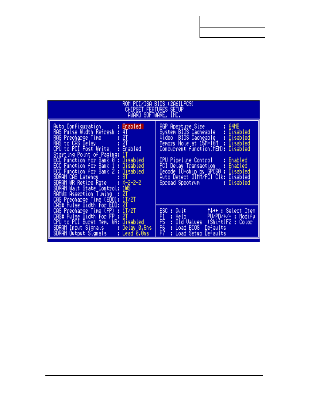
3.3 CHIPSET FEATURES SETUP
The "CHIPSET FEATURES SETUP" includes settings for the chipset dependent features. These
features are related to system performance.
Caution : Make sure you fully understand the items contained in this menu before you try to
change anything. You may change the parameter settings to improve system
performance. However, it may cause system unstable if the setting are not correct for
your system configuration.
30
Page 33

INTEL PII
User’s Guide
AUTO Configuration- Default “Enable”
RAS Pluse Width Refresh
RAS Precharge Time
RAS to CAS Delay
CPU to PCI Post Write
All value are base on DRAM controller Factory default setting(depending on the memory
modules that you are using.)
SDRAM CAS Latency - this bit contains the information for SDRAM during initialization
SDRAM WR Retire Rate - this bit controls the timing that the Intel chipset writes data into
SDRAM during burst cycles
RAMW# assertion timing – this bit for EDO/FP DRAM only
SDRAM Input SignalsSDRAM Output signals-
These control bits are used to adjust the internal SDRAM clock used to latch MD(63:0) driven
out by SDRAM. The value being programmed will be subject to SDRAM TAC specification
Memory Hole At 15M-16M
-Enabling this feature reserves 15MB to 16MB memory address space to ISA expansion cards
that specifically require this setting. This makes the memory from 15MB and up unavailable to
the system. Expansion cards can only access memory up to 16MB.
Chipset Features – AGP Aperture Size (MB)
-Memory—mapped, graphics data structures can reside in a Graphics aperture. Leave on 64MB
default setting.
Chipset Features – Auto detect DIMM/PCI Clk
- to meet the EMI specification, it will disable all un-detect DIMM CLK.
Chipset Features – Spread Spectrum
-1 Leave on default setting.
Chipset Features – Concurrent PCI/Host
- Allow PCI masters from both PCI buses active at the same time
31
Page 34
INTEL PII
User’s Guide
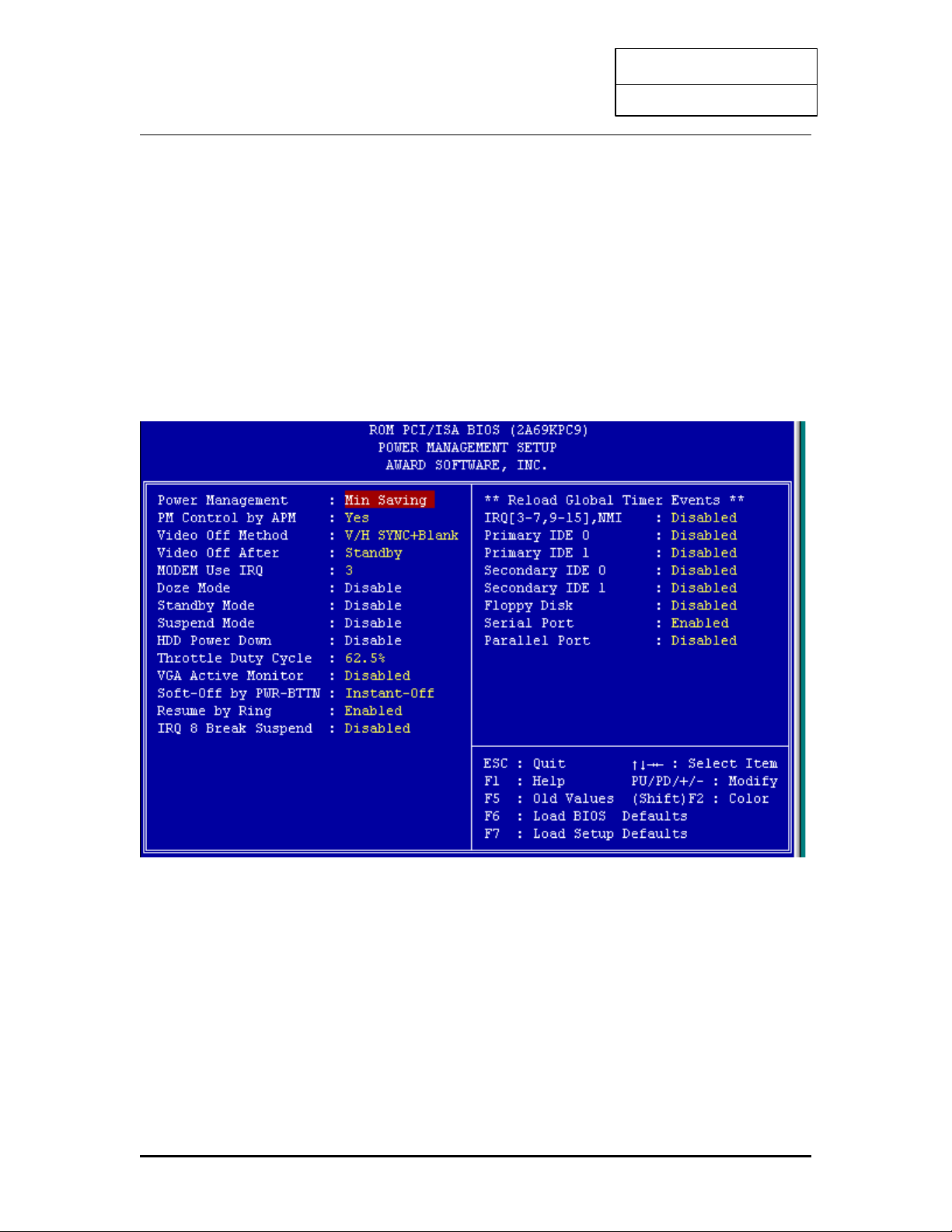
3.4 POWER MANAGEMENT SETUP
The Power Management controls the mainboard a "green" features that for the power saving
Mode, Display turn off and HDD power down that together form the hardware power
conservation scheme.
Run the Power Management Setup as follows:
1. Choose "POWER MANAGEMENT SETUP" from the Main Menu and a screen with
a list of items appears.
2. A short description of the screen items follows:
"POWER MANAGEMENT" is the master control for the four power saving modes,
doze, standby, suspend mode and HDD power down mode..
Min Saving
-The "Min saving "defaults as "1 hour", "1 hour", "1 hour" and "15 Min" respectively.
Max Saving
-The "Max Saving" defaults are all "1Min"
User define
32
Page 35

INTEL PII
User’s Guide
-Allows you to set the power mode time-out by yourself
Disable
-Turn off all power saving time-outs.
Doze mode
-Put the system performance down to 20%
Stand by mode
-Turn off the video signal and cause CPU enter SMM mode
Suspend mode
-Turn off the video signal and cause CPU enter SMM mode and shut down any IDE hard disk
drivers connected to the system.
HDD Power
-Shut down any IDE hard disk drivers in the system if they are Down not accessed.
Note: HDD Power down does not affect SCSI hard disks.
Soft-off by PWR-BUTTON
-when set to Soft Off, the ATX switch can be used as a normal system power—off button
when pressed for less than 4 seconds. If set as “ Instant-Off” , the system will be power off
at any time.
33
Page 36
INTEL PII
User’s Guide
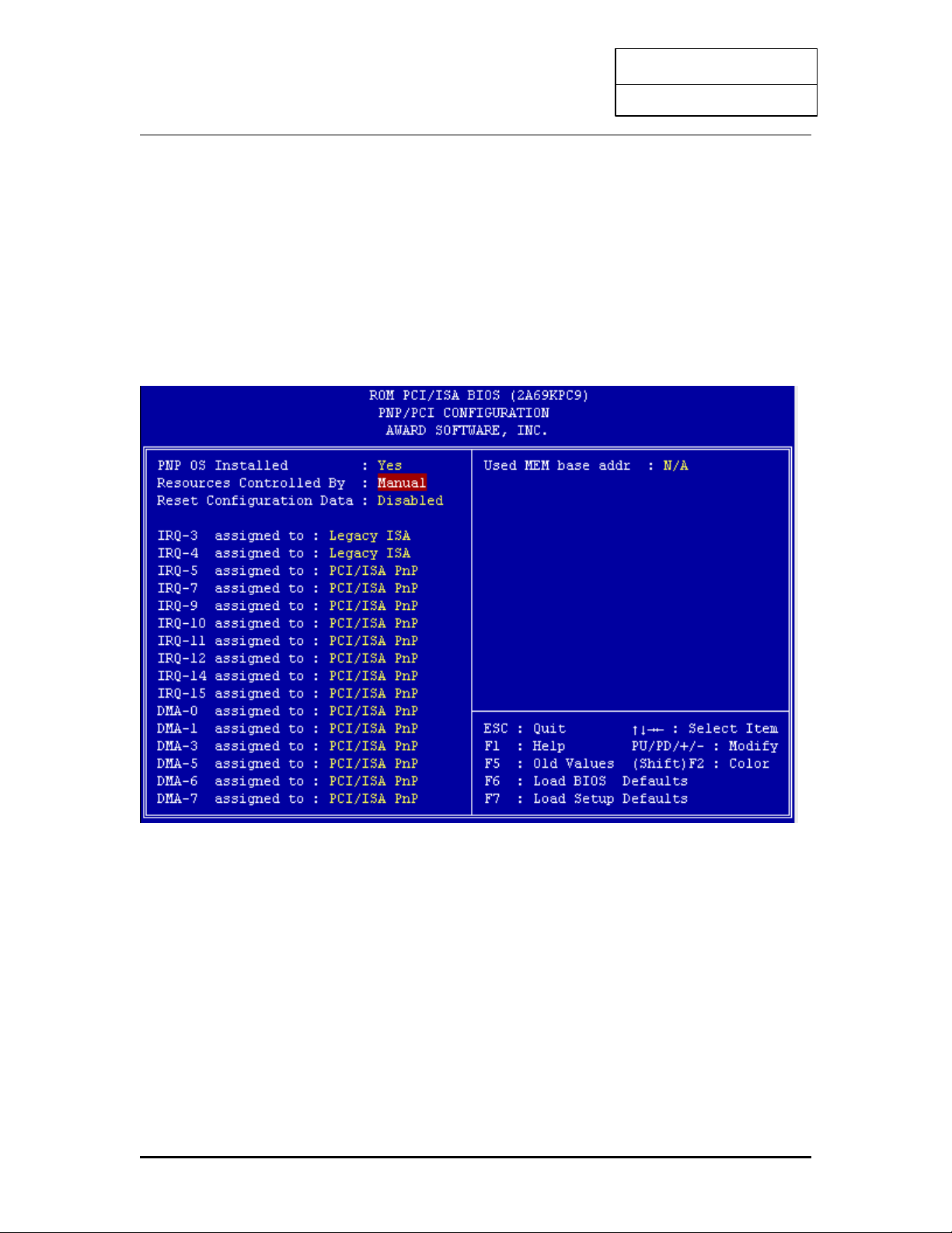
3.5 PNP/PCI SLOT CONFIGURATION
The "PNP/PCI SLOT CONFIGURATION" sets the system for use with PCI bus cards.
Run the PNP/PCI Slot Configuration program as follows.
1. Choose "PCI SLOT CONFIGURATION" from the Main Menu and a screen with a list
of items appears.
2. Use the arrow keys to move between items and to select values. Modify the selected
fields using the PgUp/PgDn/+/-keys. <F> keys are explained below:
<F1>: "Help" gives options available for each item.
<F2>: Change color
<F5>: Get the old values. The user started the current session with these
values.
<F6>: Load all options in the BIOS Features Setup with the BIOS Default
values.
<F7>: Load all options in the BIOS Features Setup with the Setup Default
values.
34
Page 37

INTEL PII
User’s Guide
1. After you have finished with the PCI Slot Configuration program, press the <ESC> key and
then follow screen instructions to save or disregard your settings.
PNP OS Installed (YES)
-This field allows you to use a Plug-and-Play (PnP) operating system to configure the PCI bus
slots instead of using this BIOS. Thus interrupts may be reassigned by the OS when YES is
selected. When a non-PnP OS is installed or to prevent reassigning of interrupt settings, select
the default setting as “YES”.
Resources Controlled By (Manual/Auto)
-setting this option to manual allows you to individually assign the IRQs and DMAs to the ISA
and PCI devices. Set this to AUTO to enable the auto configuration function.
Reset configuration Data
-Incase conflict occurs after you assign ths IRQs or after you configure your system, you can
enable this function, allow your system to automatically reset your configuration and reassign the
IRQs.
Used MEM Base address
-this item, in conjunction with the “Used MEM Length”, lets you set a memory space for non-
PnP compatible ISA card. This item specifies the memory base (start address) of the reserved
memory space. The memory size is specified in the “Used MEM length”.
Used MEM Length
-If your ISA card is not PnP compatible and requires special memory space to support its
function, specify the memory size in this parameter to inform the PnP BIOS to reserve the
specified memory space for installed legacy ISA card.
35
Page 38
INTEL PII
User’s Guide
3.6 LOAD SETUP DEFAULTS
This Main Menu item loads the default system values. These settings are recommended for
optimum performance. If the CMOS is corrupted when enter BIOS setup utility you must load
setup default again. Choose this item and the following message appears:
"Load "SETUP Defaults (Y/N)? N"
To use the Setup defaults, change the prompt to "Y" and press <Enter>.
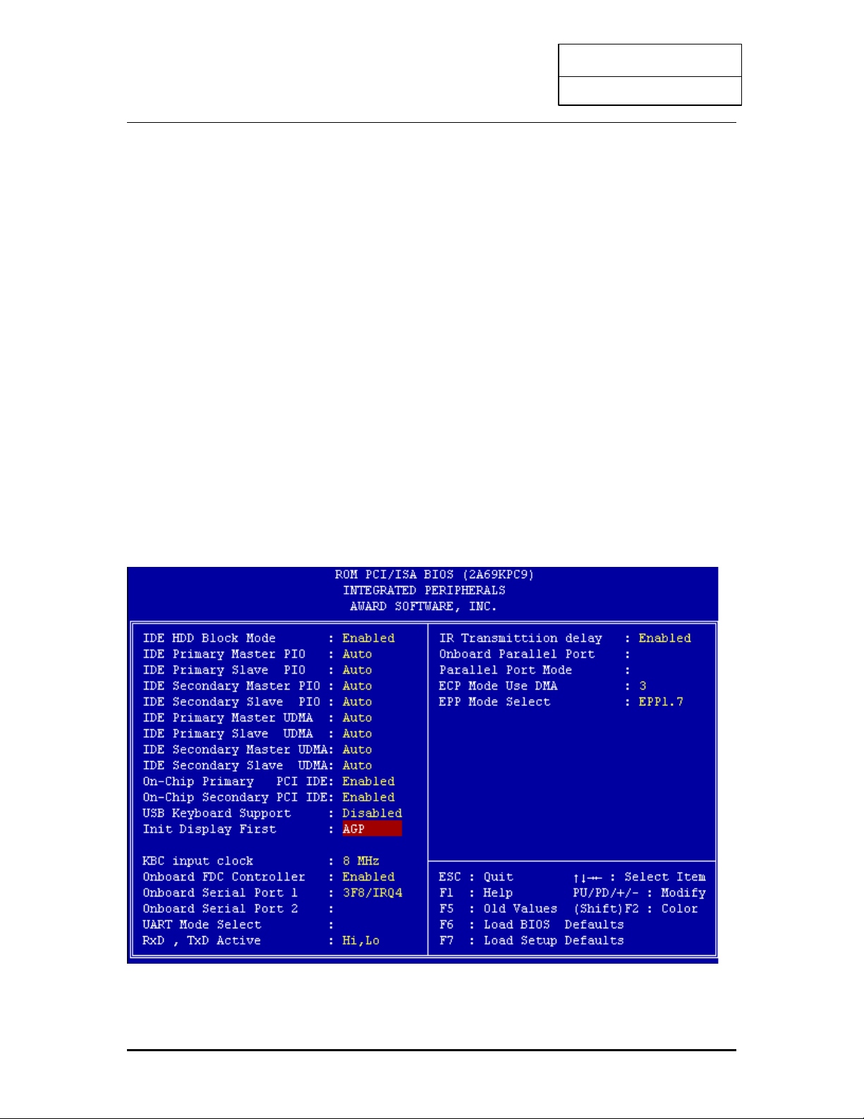
3.7 INTEGRATED PERIPHERALS SETUP
The "INTEGRATED PERIPHERALS" is used to control the values of the I/O chipset registers.
These registers control the mode of HDD type and I/O address port.
Run the Integrated Peripherals as follows:
1. Choose "INTEGRATED PERIPHERALS" from the Main Menu and a screen with a list .
36
Page 39

INTEL PII
User’s Guide
IDE Hard Disk Drive Mode Setting
The BIOS support two kind of methods to set up your IDE Hard Disk Drive Mode. One is auto, the other
is manual mode.
In auto mode BIOS can auto detect HDD's mode, but in some old type HDD that can't meet ATA
specification, the BIOS will detect wrong Mode and cause system boot fail. You must change auto mode
to manual mode and try a proper mode that can meet your HDD specification. There are five modes
defined in manual mode. They are mode 0,1,2,3,4. The default setting for on board timing is auto mode
that it will provide optimum performance for your HDD.
IDE HDD Block Mode
Choose Enabled or Disabled. If your IDE HDD supports BLOCK MODE, then you can enable this
function to speed up the HDD Access time. If not, please disable this function to avoid an HDD Access
Error.
Onboard PCI IDE Controller
The on Chip PCI IDE controller is default "Enable" setting, if you disable On-Chip primary and secondary
PCI IDE, it will disable the on board IDE controller. Make sure you do this if you want to use an IDE
controller other than on the mainboard IDE controller.
Onboard FDD Controller
The default setting for the "Onboard FDC Controller" is "Enabled". This setting allows you to connect
your floppy disk drives to the onboard "Floppy" connector. Choose the "Disabled" setting if you want to
use a separate controller card.
Serial Port
The "Onboard Serial Port 1" and "Onboard serial Port 2" lines control the assignments for the mainboard's
two onboard serial connectors. They can be assigned as COM1, COM2, COM3, COM4 for serial Port 1
and serial Port 2, or disable.
Parallel Port
The options for "Onboard Parallel Port" is 378H. This item controls the on-board parallel port connector,
if you are using an I/O card with a parallel port, make sure the address don't conflict.
Parallel Port Mode
The options for "Onboard LPT Port Mode" is default SPP mode, you can select EPP, ECP, and SPP Mode
just change setting, if you have a parallel interface peripheral device, use one of the parallel port
enhancements and set this line for the enhanced mode that your peripheral supports.
ECP Mode Use DMA
The option for "ECP Mode use DMA" is default DMA3 if your system has ECP preheat device, when you
are using some I/O card, make sure the DMA channel don't conflict. When you have done with this
section, press the <ESC> key to go back to the main screen.
37
Page 40
INTEL PII
User’s Guide
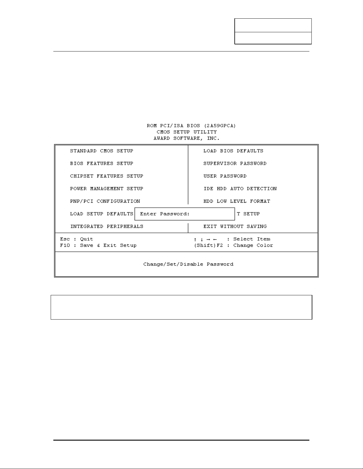
3.8 USER PASSWORD SETUP
This Main Menu item lets you configure the system so that a password is required every time the
system boots or an attempt is made to enter the Setup program. The password cannot be longer
than 8 characters.
Important: Keep a safe record of the new password. If you forget or lose the password,
the only way to access the system is to discharge CMOS memory using jumper
JP11.
38
Page 41

INTEL PII
User’s Guide
3.9 IDE HDD AUTO DETECTION
1. If your system has an IDE hard drive, you can use this utility to detect its parameters and
automatically enter them into the Standard CMOS Setup.
ROM PCI / ISA BIOS (2A59GF51)
IDE HDD AUTO DETECTION
AWARD SOFTWARE, INC.
For IDE hard disk driver, the BIOS provide three modes to support both normal IDE hard
disk and also drivers large than 528MB, a short description of three modes as follows:
a. Normal mode: For drivers small than 528MB
b. Large mode: For drivers larger than 528MB that do not use LBA. There can
only be used with MS-Dos operating system.
c. LBA mode: For drivers larger than 528MB and upto 8.4GB that use logic
block addressing mode. Normally we recommend to select LBA
Mode if your HDD drivers large than 528MB.
3. This utility will autodetect as many as four IDE drivers.
39
HARD DISKS TYPE SIZE CYLS HEAD PRECOMP LANDZ SECTOR
MODE
Primary Master:
Select Primary Master Option (N=Skip):N
OPTIONS SIZE CYLS HEAD PRECOMP LANDZ SECTOR
MODE
2(Y) 21 699 32 0 1398 63 LBA
1 722 1399 16 65535 1398 63 NORMAL
2 721 699 32 65535 1398 63 LARGE
ESC : SKIP
Page 42
INTEL PII
User’s Guide
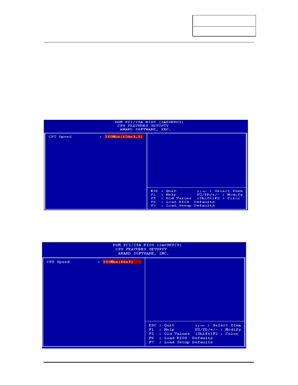
3.10 CPU SPEED SETTING
The mainboard will auto detect your Pentium II CPU is 100MHz type or 66MHz type , and the
table will shown a correct frequency table , the user may chose the correct CPU SPEED for the
system.
100MHz type CPU:
66MHz type CPU:
40
Page 43

INTEL PII
User’s Guide
3.11 SAVE & EXIT SETUP
Select this item from the main menu and type "Y" to save the values entered during the current
session and then exit the BIOS Setup program. Type "N" to return to the Setup program.
3.12 EXIT WITHOUT SAVING
Select this item from the main menu and type "Y" to exit the BIOS Setup program without
saving the values entered during the current session. Type "N" to return to the Setup program.
41
Page 44

INTEL PII
User’s Guide
4. DRIVER INSTALLATION
4.1 Windows 95 SYSTEM INFO. update Installation
(Driver CD or Diskette bundled)
The installation procedures described here were based on the Windows 95 Final Release
version.
1. Insert the floppy disk containing the driver file into drive A (or B). (or insert CD in CDROM drive)
2. Double click the “My Computer” icon on the Desktop screen.
3. Double click the drive A (or B) icon. (or CD-ROM drive)
4. Run SETUP.EXE in drive A (or B) :\Win95 (or CD directory: \Intelmb\setup.exe)
5. Follow the advise showed on the screen to complete the installation.
6. When system prompted to reboot Windows 95, select “Yes”
7. Restart Windows 95 will detect Intel 82371AB PCI IDE Controllers and install the primary
and secondary IDE controller in sequence.
8. And the System devices, Intel 82371AB PCI to ISA Bridge, Intel 82371AB power
Management Controller, Intel 82443BX PentiumÒ Processor to PCI Bridge will be
created and recognized.
9. Restart Windows 95 again.
4.2 PCI card ( or PCI Universal serial devices):
If you are WIN95 OSR 2.0 user (it shows “PCI Universal serial Devices”), you may obtain
USBSUPP.exe from Microsoft or our AGP product driver for installing Microsoft USB
supplement which create “USB Supplement to OSR2” in the list of ADD/Remove program tool
under Control Panel. After USBSUPP.exe update, run WIN95 SYSINFO uupdate (driver
diskette) setup.exe again.
4.3 Crystal Sound -- Windows 95 / 98 Driver Installation
1. During the Windows 95 / 98 boot procedure, new hardware will be detected as shown below.
2. Select the “Driver from disk provided by hardware manufacture” item, and click the
“OK” button.
3. Windows 95 / 98 will then prompt a “Install From Disk” dialog box.
4. Insert the CD into CD-ROM Drive and click the “Browse...” button to choose the letter of
CD-ROM Drive ( for example “D:\” ), and type “CX4235\Win95 or Win98\ ” ( for example
D:\CX4235\Win95\ ), then click the “OK” button to install the Windows 95 / 98 driver. For
other languages replace English with the language of your choice.
5. Follow installation procedure.
42
Page 45

INTEL PII
User’s Guide
Problem: There is problem in playing audio CD after reinstalling Windows 98 ?
Answer: During re-installation of Windows 98, Win98 will auto-detect the Crystal sound device
on board and use its default driver of Crystal 4235 sound. However, this default driver is not
specifically designed for this Crystal 4235 chipset. Therefore, whenever you encounter this
problem, please delete the default driver and re-install the correct driver from the CD supplied
by the mainboard manufacturer.
Procedures:
1. Run Device Manager which is located in the System option under Control Panel.
2. Delete the Win98 default driver of Crystal sound.
3. Run the Setup program of Crystal sound (directory X:\CX4235\win98, X: - CD-ROM
drive )from the CD supplied by the mainboard manufacturer.
4. Re-install the correct driver of Crystal 4235 sound device.
4.4 Yamaha 128 Voice (S-YXG50) Installation
1. Start Win 95 / 98.
2. Insert the CD disk into the CD-ROM drive. (e.g. Drive D)
3. Choose ‘”Run” from the Start Menu.
4. Type “D:\Yama_128\XG-50\English\setup.exe” on the command line, then click on the
“OK” button.
5. Note that for S-YXG50 instead of English, you can choose French, German, Italian, Japanese
or Spanish.
6. A Welcome dialogue box will appear, click the “Next” button to start the installation.
7. When the user information dialogue box appears, it will ask for a serial number. Please type
in CAPITAL letters “G5AAH98P1013”
8. The heart of this software can be located in the XG Synth Driver icon under the Control
Panel.
4.5 Yamaha XG Studio Mixer Software Installation
1. Start Win 95 / 98.
2. Insert the CD disk into the CD-ROM drive. (e.g. Drive D)
3. Choose ‘”Run” from the Start Menu.
4. Type “D:\Yama_128\xgstudio\setup.exe” on the command line, then click on the “OK”
button.
5. A Welcome dialogue box will appear, click the “Next” button to start the installation.
6. Follow the instructions on screen.
7. To assess the software, double click on the XGStudio Mixer option in the YamahaXG
Studio menu located inside the Program menu.
43
Page 46

INTEL PII
User’s Guide
4.6 BIOS Upgrade
Before upgrading the BIOS of this Intel mainboard, please check the BIOS size whether it is 1M
or 2M. The BIOS size will be displayed on the monitor screen during system boot-up. Then
download the correct size and version of BIOS from supplier’s website.
Our Website: www.pine-tech.com
4.7 Installing ATAPI CD-ROM
1. This board offers two E-IDE (Enhanced IDE) connectors, each of which can take two
devices. Please set the primary channel for E-IDE hard disks and set the secondary
channel for slow throughput ATAPI compliant peripherals (such as ATAPI CD-ROM).
2. If you are installing a secondary E-IDE drive, you may have difficult getting the two drives to
work together since some brands of E-IDE drivers won’t work on the same bus as another
brand. You will have to designate one drivers as master and another as slave.
44
Page 47

INTEL PII
User’s Guide
APPENDIX I
On Board I/O Address & IRQ Maps
System Resource IRQ I/O Address
Timer IRQ0 040-043
Keyboard IRQ1 060-064
Programable INT Controller IRQ2 0020-0021
00A0-00A1
COM2 (B) IRQ3 2F8-2FF
COM1 (A) IRQ4 3F8-3FF
Floppy IRQ6 3F0-3F7
LPT1 IRQ7 378-37F
Real Time Clock IRQ8 070-071
PS/2 Mouse IRQ12
Math Coprocessor IRQ13 0F0-0FF
IDE 1 IRQ14 1F0-1F7
IDE 2 IRQ15 170-177
Note : IRQ 5,9,10 and 11 will be available for other interface card.
Our Website: www.pine-tech.com
45
 Loading...