


Model 541
Frequency Calibrator
with Totalizer
Practical Instrument Electronics
A. Basic Keypad Operations
Operating Instructions
1 EZ-Check™ Switch/EZ-Step™ Pushbutton
Slide the switch to select the user stored
values for calibration points.
Push the EZ-Step™ pushbutton like a stop
Watch to Run or Stop Totalizing.
3 ON/OFF Button
Press ON/OFF to turn the Model 541 on or off.
4 MENU Button
Press and release the menu button and a
mode of operation menu will appear with all
the selections for operation mode.
REFER TO SECTION B.
5 READ/GATE TIME Button
Press and release READ/GATE TIME to
change read modes. These are:
• Read Source CPH 1 – 20000
• Read CPM 0.1 – 2000.0
• Read HZ 0.01 – 200.00
• Read HZ 0.1 – 2000.0
• Read KHZ 0.001 – 20.000
• Totalizer
Press and hold READ/GATE TIME to select
gate time adjustment for Source & Read
Totalize mode.
Then press the SOURCE/AMPLITUDE or
STORE/CLEAR button to save selections and to
exit.
h STORE/CLEAR Button
In source mode press the STORE/CLEAR to
save the calibration values. The display will
2 SOURCE/AMPLITUDE Button
Press and release SOURCE/AMPLITUDE
to change source modes. These are:
• Source CPH 1 - 20000
• Source CPM 0.1 – 2000.0
• Source HZ 0.01 – 200.00
• Source HZ 0.1 – 2000.0
• Source KHZ 0.001 – 20.000
• Totalizer
Press and hold SOURCE/AMPLITUDE to
change amplitude voltage from 0.1-12Vp.
Then press the SOURCE/AMPLITUDE or
STORE/CLEAR button to save selections and
to exit.
841 Holt Road #1 • Webster, NY 14580 Tel: 585-872-9350 • Fax: 585-872-2638 sales@piecal.com • http://www.piecal.com/
Practical Instrument Electronics, Inc. Copyright 2003. All rights reserved.
i EZ-Dial™ Knob
flash “STORED” to confirm.
In read mode press STORE/CLEAR to clear
the values saved in the EZ-Check HI and LO
positions. The display will flash “CLEARED” to
confirm.
Source mode -Turn the EZ-Dial knob to
adjust the output level. Press and turn to
adjust 100X faster.
Read mode – Turn the EZ-Dial™ knob to
adjust the trigger level.
541-9002 6/25/04
1-8

Model 541 Operating Instructions
B. Model 541 Configuration
Press the MENU BUTTON on the Model 541 after you turn the unit on to
access the configuration mode. Turn the EZ-Dial Knob to select
configuration items. Press the EZ-Dial Knob to change configuration
items. Then press the Menu or STORE/CLEAR button to save selections and
to exit.
Auto Off - ON (default)/OFF
Auto Off is ON, by default, to save battery life by turning the unit off after 30 minutes of inactivity. Turn
Auto Off to OFF to prevent automatic shutdown. This is typically useful for manual loading or continuous
use.
X1/X10 - X1 (default)
This selection is for attenuation of input signals factored by X1 or by X10, X1 for voltage between1 -12Vpk
or X10 for voltages between1 - 120Vp.
0 XING/BASED Based (default)
This selection gives the users the ability to change output signals between Zero Based and Zero Crossing.
This gives the user the ability to select 0 XING for Zero Crossing Square or Sine waves to be able to output
signals that go from positive to negative. Zero Based Square Wave to output only positive signals.
NOTE: FOR SIMULATING NEGATIVE ONLY SIGNALS, SWAP THE BLACK AND RED LEAD WIRES IN
ZERO BASED MODE.
EZ-Check HI/LO Readings ON (default)
If the EZ-Check HI/LO Readings option is ON, the highest and lowest readings will automatically be saved
in the HI and LO EZ-Check™ positions.
If this option is OFF the HI and LO positions will show the current reading.
SINE/SQ SQ (default)
This selection gives the users two choices to choose from for an output signal:
Sign Wave Signal or Square Wave Signal
BASIC CONFIGURATION
If Basic Configuration is selected, the unit will restore all factory defaults. This will reset any changes made
in the Model 541 Configuration options, returning the unit to its simplest factory configuration. Which
means Auto Off is on, range at x1, Zero Based Square Wave, EZ-Check is on and Square wave is selected.
841 Holt Road #1 • Webster, NY 14580 Tel: 585-872-9350 • Fax: 585-872-2638 sales@piecal.com • http://www.piecal.com/
Practical Instrument Electronics, Inc. Copyright 2003. All rights reserved.
541-9002 6/25/04
2-8

Model 541 Operating Instructions
C. EZ-Dial Knob
Source mode - Adjust the output up and down with the EZ-Dial knob. The increment is the far right digit
(XXXX1). Press while turning to adjust 100X faster (XX1XX)
Read mode – Trigger level adjustment. Adjust knob until LED Blinks and Reading is displayed.
D. EZ-Check Switch
The EZ-Check™ switch has three positions -- high, set, and low. Its position is shown at the left edge of the
LCD display with “HI” and “LO” indicators. Use of the EZ-Check switch depends on mode:
Source Modes:
Hint: For faster calibrations, the position of the switch can be felt. This feature allows continuous monitoring
of the device being calibrated without looking back at the Model 541 display. This is also useful in poor
lighting or under difficult operating conditions.
Read Modes:
Slide the EZ-Check switch to the HI and LO positions to recall the settings stored in those
positions. While in the HI and LO positions, dial the EZ-Dial knob to change the display. Press
STORE/CLEAR to save new settings in the HI and LO positions. The display will flash “STORED” to
confirm.
In read modes, with the EZ-Check switch in the middle position, the Model 541 calibrator records
the maximum and minimum readings observed in each mode. Slide the EZ-Check switch to the HI
and LO positions to display the readings. Press STORE/CLEAR to clear the readings. The display will
flash “CLEARED” to confirm.
E. TOTALIZE Pushbutton
The EZ-Step Switch pushbutton is a feature for read and source modes.
Push the EZ-Step™ like a stop watch to run or stop Totalizing.
F. FREQUENCY OUTPUT (SOURCE MODE)
Press the SOURCE button to select the Frequency output mode, the word Source will appear on the LCD
Display. Press the SOURCE button to select the desired frequency range. Press and hold the
Source/Amplitude button to enter the Amplitude adjustment screen. Then turn the EZ-Dial knob to select
the desired Level (amplitude) this will be indicated on the LCD. Levels are indicated in Vp and Vpp with
respect to the black lead (-). Then press the SOURCE/AMPLITUDE or STORE/CLEAR button to save
selections and to exit.
You are able to setup three desired set points for quick calibration. Use the EZ-Check
the EZ-Check switch to the HI and dial the EZ-Dial to the desired set point. Press the STORE/CLEAR
button to save settings. Do the same in the LO positions. For the mid range just dial it to the set point. It
will stay at that point unless you move the EZ-Dial. This is so you may test linearity in the mid range
while maintaining the 0% and 100% end points.
Connect the Model 541 to the output of the equipment or sensor to being calibrated then slide the EZ-Check
switch to the HI, MIDDLE and LO positions to recall the settings stored in those positions.
If you need to change set points, while in the HI and LO positions, dial the EZ-Dial knob to change the
display. Press STORE/CLEAR to save new settings in the HI and LO positions. The display will flash
“STORED” to confirm.
slide switch. Slide
841 Holt Road #1 • Webster, NY 14580 Tel: 585-872-9350 • Fax: 585-872-2638 sales@piecal.com • http://www.piecal.com/
Practical Instrument Electronics, Inc. Copyright 2003. All rights reserved.
541-9002 6/25/04
3-8

Model 541 Operating Instructions
G. FREQUENCY COUNTER (READ MODE)
Press the READ button to select the READ mode, the word READ will appear on the LCD Display. Press the
READ button to select the desired frequency range. Press the Menu button and select the Level (amplitude)
X1 for signals 0.1 to 12Vp or X10 for signals from 1 to 120Vp. Then press the READ/GATE TIME or
STORE/CLEAR button to save selections and to exit.
In read modes, the Model 541 calibrator records the maximum and minimum readings observed in each
mode. Connect the Model 541 to the equipment or sensor being measured and use the EZ-Check
switch in the center position to monitor the frequency. Slide the EZ-Check switch to the HI and LO
positions to display the min. & max. readings. Press STORE/CLEAR to clear the readings. The display will
flash “CLEARED” to confirm.
H. FUNCTION OF THE GREEN LED
The Model 541 is equipped with a GREEN LED light. It is being used in the Read mode to let the user know
that their signal is being detected by the calibrator when the LED is flashing. If the LED is not lit, the user
must adjust the trigger level. NOTE: Led will appear solid above Frequency of 60Hz.
I. TOTALIZE (READ MODE)
slide
The Model 541 will count pulses with-in the users defined period. Press the Menu button and select the Level
(amplitude) X1 for signals 0.1 - 12Vp or X10 for signals from 1V to 140Vp. Then press the Menu or
STORE/CLEAR button to save selections and to exit. Press the READ/GATE TIME button and select the
TOTALIZER mode. Press and hold the READ/GATE TIME button and adjust the number of minutes (1-100) that
you want the Model 541 to count pulses. Then press the READ/GATE TIME or STORE/CLEAR button to save
selections and to exit. Then turn the EZ-Dial knob to adjust the trigger time. This will be indicated on the LCD.
Connect the Model 541 to the output of the equipment or sensor being measured and push the EZ-Step push
button on the side of the unit, similar to a Stop Watch, to run or stop Totalizing. The words RUN or STOP will
appear on the LCD display.
See Totalizer Connections on next page.
J. CALIBRATE TOTALIZERS (SOURCE MODE)
The Model 541 will count pulses with-in a selected time frame. Press the SOURCE/AMPLITUDE button and
select the TOTALIZER mode. Press and hold the READ/GATE TIME button and adjust the number of minutes
(1-100) that you want the Model 541 to output pulses. Then press the SOURCE/AMPLITUDE or
STORE/CLEAR button to save selections and to exit. Then turn the EZ-Dial knob to adjust the number of pulses
required during the time period defined. This will be indicated on the LCD.
Connect the Model 541 to the output of the equipment or sensor to be calibrated then Slide the EZ-Step
switch to the HI, MIDDLE and LO positions to recall the settings stored in those positions.
See Calibrate Totalizers Connection diagram on next page.
841 Holt Road #1 • Webster, NY 14580 Tel: 585-872-9350 • Fax: 585-872-2638 sales@piecal.com • http://www.piecal.com/
Practical Instrument Electronics, Inc. Copyright 2003. All rights reserved.
541-9002 6/25/04
4-8
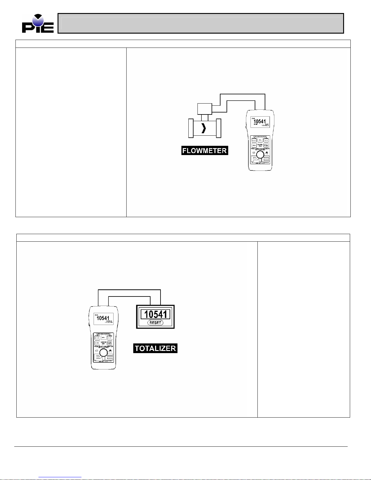
Connect the Model 541 to the output
of the equipment or sensor to be
measured and push the EZ-Step
pushbutton like a stop watch to run
or stop Totalizing. The words RUN
or STOP will appear on the LCD
display.
Model 541 Operating Instructions
TOTALIZE CONNECTIONS
CALIBRATE TOTALIZERS
Connect the Model 541 to the
input of the equipment or
sensor to be calibrated. Slide
the EZ-Check switch to the
HI and LO positions to recall
the settings stored in those
positions.
841 Holt Road #1 • Webster, NY 14580 Tel: 585-872-9350 • Fax: 585-872-2638 sales@piecal.com • http://www.piecal.com/
Practical Instrument Electronics, Inc. Copyright 2003. All rights reserved.
541-9002 6/25/04
5-8

Model 541 Operating Instructions
K. Specifications
General Specifications:(Unless otherwise indicated all specifications are rated from a nominal 23
°C, 70 % RH for 1 year from calibration)
Operating Temperature Range -20 to 60 °C (-5 to 140 °F)
Storage Temperature Range -30 to 60 °C (-22 to 140 °F)
Relative Humidity Range 10 % RH 90 % (0 to 35 °C), Non-condensing
Size 7.00 X 3.30 X 2.21 inches (177.8 x 83.8 x 56.1mm)
Weight 12.0 oz (340 grams)
Battery 9V Alkaline
Miscellaneous Low battery indication with nominal 1 hour of operation left
Frequency Ranges 1CPH to 20.000Khz
Accuracy ± 0.005% of range
Temperature Effect 10ppm/°C of range
10 % RH 70 % (35 to 60 °C), Non-condensing
Over-voltage protection to 120 Vrms (rated for 30 seconds) or 240 Vrms
(rated for 15 seconds)
High contrast graphic liquid crystal display with 0.45” (11.4 mm) high digits
Common Specifications for all Frequency Modes:
Frequency Ranges Specifications:
1 1 CPH< CPH Range < 20000 CPH
2 0.1 CPM (0.0167Hz)< CPM Range < 2000.0 CPM (33.33Hz)
3 0.01Hz < Hz < 200.00Hz
4 0.1Hz < Hz Range < 2000.0Hz
5 0.001KHz < KHz Range < 20.000KHz
6 Totalize inputs/outputs from 1 to 99999 counts in 1 minutes to 100.0 minutes
Read Inputs Specifications:
Read x1 attenuation range: 0.1Vpk to 12Vpk
x10 attenuation range: 1Vpk to 120V peak – Limit of attenuation is 120Vpk
Input Impedance > 1 Meg + 100pF
Adjustable Signal Attenuation Adjustable trigger level with X1 and X10 attenuation ranges
Miscellaneous Battery life 24 hour typical
Fuse-less protection 240Vrms
Waveforms Source Specifications:
Output current >6mApp at 12Vpp output, 20KHz
Output Impedance < 25
Square Wave:
Zero Crossing, Zero Based Selectable
Rise/Fall Time < 0.0001% of output Vpk per Second
Frequency Jitter < 0.5LSB of frequency range
Duty cycle 50% ± 2%
Sine Wave:
Offset and Zero Crossing
<± 10% of Vpk Output amplitude setting
Symmetry
Amplitude Adjustment 100mV < Nominal Output < 12Vpp ± 10% of setting
841 Holt Road #1 • Webster, NY 14580 Tel: 585-872-9350 • Fax: 585-872-2638 sales@piecal.com • http://www.piecal.com/
Practical Instrument Electronics, Inc. Copyright 2003. All rights reserved.
541-9002 6/25/04
6-8

Model 541 Operating Instructions
NIST Traceable Certificate provided
Option:
Option: Part Number:
Carrying Case 020-0200
RTD Source (Single Type/1° resolution) Model 510
RTD Source (7 Types, /0.1° resolution)
Pt100: =1.3850, 1.3902, 1.3916, 1.3926
Cu10: =1.427
Ni110: =1.530
Ni120: =1.672
RTD Calibrator (Source/Read 7 Types, /0.1° resolution) Model 512
T/C Source (Single Type/1° resolution) Model 520
T/C Source (8 Types, mV/0.1° resolution)
T/C Calibrator (Source/Read 8 Types, mV/0.1° resolution)
B, E, J, K, N, R, S, T, mV
4-20 Milliamp Loop Calibrator Model 530
4-20 Milliamp/Voltage Calibrator with Loop Diagnostics Model 532
4-20/10-50 Dual Range Loop Calibrator Model 535
Calibration Certificate:
Test data available upon request at additional charge.
Available Options:
Model 541 BNC With a BNC connector ADDED CHARGE OF $50.00 to the list of the 541
Other Products Available:
Model 511
Model 521
B, E, J, K, N, R, S, T, mV
Model 522
841 Holt Road #1 • Webster, NY 14580 Tel: 585-872-9350 • Fax: 585-872-2638 sales@piecal.com • http://www.piecal.com/
Practical Instrument Electronics, Inc. Copyright 2003. All rights reserved.
541-9002 6/25/04
7-8

Model 541 Operating Instructions
L. Warranty
Our equipment is guaranteed against defective material and workmanship (excluding batteries) for a period of three years from the
date of shipment. Claims under guarantee can be made by returning the equipment prepaid to our factory. The equipment will be
repaired, replaced or adjusted at our option. The liability of Practical Instrument Electronics (PIE) is restricted to that given under our
guarantee. No responsibility is accepted for damage, loss or other expense incurred through sale or use of our equipment. Under no
condition shall Practical Instrument Electronics, Inc. be liable for any special, incidental or consequential damage.
841 Holt Road #1 • Webster, NY 14580 Tel: 585-872-9350 • Fax: 585-872-2638 sales@piecal.com • http://www.piecal.com/
Practical Instrument Electronics, Inc. Copyright 2003. All rights reserved.
541-9002 6/25/04
8-8
 Loading...