

Page 1
Electronics
1-4
j
ƒ
Test Equipment Depot - 800.517.8431 - 99 Washington Street Melrose, MA 02176 - TestEquipmentDepot.com
PIECAL 134
4-20 Milliamp Loop Calibrator
Operati n g Instructions
Practical Instrument
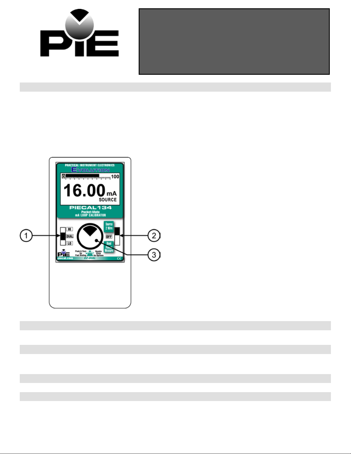
Basic Keypad O pera tions
EZ-Check™ Switch
SOURCE mo
set values and the mid ranger (Dial) is selectable. Dial the mid range
value and it will store the value with-in 5 seconds automatically.
READ mod
readings. Press the EZ-Dial™ Knob to clear the stored values.
de: Slide the switch to select from Hi and low range pre-
e: Slide the switch to recall minimum and maximum
k SOURCE/OFF/READ Switch
the SOURCE/OFF/READ Switch to SOURCE to
Slide
output a mA signal and to do 2 - wire transmitter
simulation. Use the READ position to read mA signal and
power & measure 2 – wire transmitter.
EZ-Dial™ Knob
Turn the knob to change display in 0.01mA increments.
Push and turn for faster dialing. Push without turning to
clear EZ-Check™ HI/LO points in READ mode.
Press tw
In Sourc
% or mA
2-Wire Transmitter Simulate
% or mA
low power (15V) or High power (24V)
In Read mo
% or mA
Power and Measure 2-Wire Transmitter
% or mA
low power (15V) or High power (24V)
ice to select options:
e mode select –
de select -
HART® Protocol
An internal jumper enables the Power & Measure 2 – wire
transmitter mode to be compatible with HART®
communicators and transmitters.
EZ-Dial™ Knob
Adjust the output up and down with the EZ-Dial knob. The increment is 0.01 mA (or 0.1 % if display units are % of 4-20 mA.)
Press while turning to adjust 10X faster – 0.10 mA (or 1.00 %.)
Quick Referen ce Ba r Gra ph
The Quick Reference Bar Graph indicates the input and output level to the PIECAL 134 in % of 4-20 mA with 1.0% resolution. If the
input or output signal is outside the normal operating range of the PIECAL 134 the Quick Reference Bar Graph in source mode will
flash, in Read mode display over range when above 24.5mA.
Error Cond itions
Bar Graph wi ll flash when any error condit ions exist.
HART® Pr otocol
Remove the back of the case and remove the jumper that is located in position J6 on the PC board. By doing so it places a 250Ω
resister in series with the output of the PIECAL 134. This internal resister eliminates the need to add an external load resister when
communicating with a HART® transmitter. This reduces the typical drive capability to 950Ω.
Test Equipment Depot - 800.517.8431 - 99 Washington Street Melrose, MA 02176
TestEquipmentDepot.com
Page 2
PIECAL 134 Op e rating Instructions
2-4
T r a n s m i t t e r
I n p u t ( S e n s o r ) ( P r o c e s s
S i g n a l )
( S i m u l a t e
d
I n p u t
)
R e c e i v e
r
P o w e r
S u p p l
y
0
t
o
6
0
V D C
T y p i c a l 2 - W i r e T r a n s m i t t e
r
T r a n s m i t t e r I n p u t ( S e n s o r )
( P r o c e s
s
S i g n a l ) ( S i m u l a t e d I n p u t
)
R e c e i v e r P o w e r
S u p p l y 0 t
o 6
0 V D C
T y p i c a l
2 - W i r
e
T r a n s m i t t e r
+ I N - R E F + O U T
-
EZ-Check™ Switch
The EZ-Check™ switch has three positions -- high, dial, and low. Its position is shown at the left edge of the display with “HI” and
“LO” indicators. Neither indicator indicates the middle position. Use of the EZ-Check switch depends on mode.
Source Modes:
Read
Slide the EZ-Check switch to the HI and LO positions to recall the preset settings (Hi=20.00mA & Lo=4.00mA).
Hint
: For faster calibrat ion s, the p o sition of the switch can be felt. This fe a ture a llows continuous monitoring of the d e vice
being calibrate d wit hou t look ing b a ck at the PIECA L 134 d isplay. This is also useful in poor lig h ting or under difficult
operating condition s.
Modes:
In read mode, the PIECAL 134 calibrator records the maximum and minimum readings observed in each mode. Slide the
EZ-Check switch to the Dial position to read the loop. Then Slide the EZ-Check switch to the HI and LO positions to
display the max and min readings. Press
confirm.
EZ-Dial knob to clear the readings. The display will flash “CLEARED” to
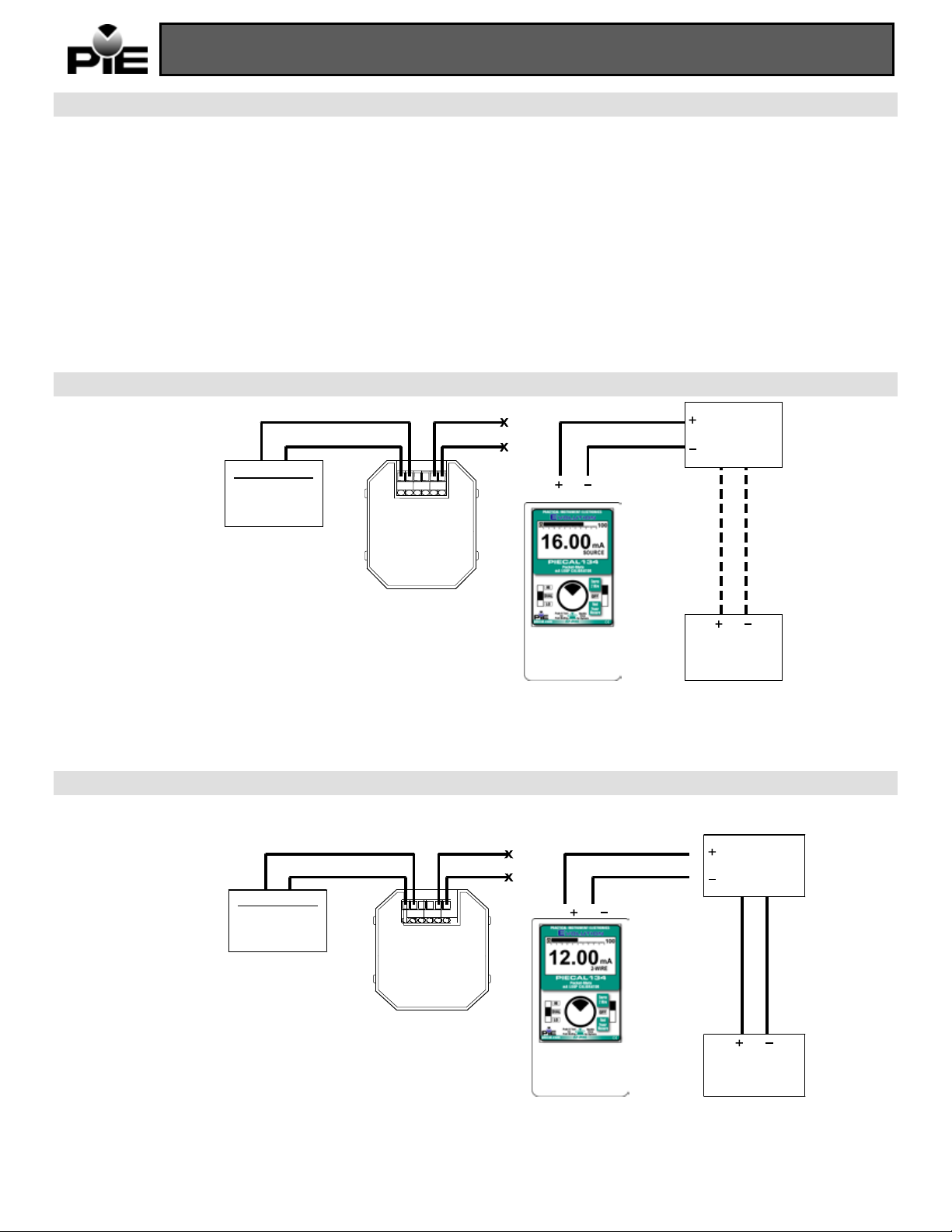
Source Mode
+ I N - R E F + O U T -
Source mode uses internal power to supply current from 0.00-24.00 mA into as much as 1200Ω until the end of battery life. The
calibrator Graph will flash if connected improperly. The three-position EZ-Check switch provides instant preset 4mA at zero, 12mA at
mid range and 20mA at full scale outputs. The output is adjusted in 0.01 or 0.10 mA increments (0.1 or 1.0) % display units with
the EZ-Dial knob.
2-Wire Transm itter S imulation Mode
The PI
ECAL 134 can simulate a 2-wire transmitter in the 4-20 mA or % process loop. In source mode press the EZ-Dial™ Knob twice
to get into the feature options. Then press the EZ-Dial™ Knob to select mA 2 – wire. The EZ-Check switch and EZ-Dial knob allow
rapid and fine control of loop current.
Test Equipment Depot - 800.517.8431 - 99
TestEquipmentDepot.com
Washington Street Melrose, MA 02176
Page 3
PIECAL 134 Op e rating Instructions
3-4
T r a n s m i t t e r
I n p u t ( S e n s o r )
( P r o c e s
s
S i g n a l ) ( S i m u l a t e d
I n p u t
)
R e c e i v e
r
P o w e r
S u p p l
y
0
t
o
6
0
V D C T y p i c a
l
2 - W i r
e
T r a n s m i t t e r
+
I
N -R E F + O U T
-
T r a n s m i t t e r
I n p u t ( S e n s o r ) ( P r o c e s s
S i g n a l )
( S i m u l a t e
d
I n p u t ) R e c e i v e r P o w e r
S u p p l y 0
t
o
6
0
V D C
T y p i c a l
2 - W i r
e
+ I N - R E F + O U T
-
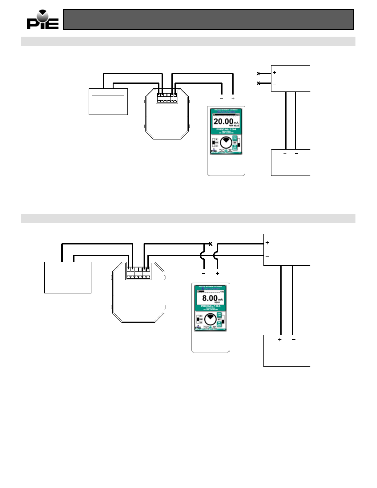
Power and Meas ur e Tra n smitter Mode
T r a n s m i t t e r
PIECAL 134 supplies 15Volts or 24 Volts to the transmitter and displays the output in mA or % on the PIECAL 134 display. In
The
read mode press the EZ-Dial™ Knob twice to get into the feature options. Then press the EZ-Dial™ Knob to select mA PWR - M. Then
turn EZ-Dial™ Knob to select power range (15V or 24V). The EZ-Check switch and EZ-Dial knob allow rapid and fine control of loop
current.
Read Mode
The PIECAL 134 can read loop currents from 0-24 mA. The PIECAL 134 limits current in read mode to 25mA to protect the devices in
the loop from over voltage or over current conditions.
Test Equipment Depot - 800.517.8431
- 99 Washington Street Melrose, MA 02176
TestEquipmentDepot.com
Page 4

PIECAL 134 Op e rating Instructions
4-4
Operating Temperature Range
-20 to 60 °C (-5 to 140 °F)
Miscellaneous
Low battery indication with nominal 1 hour of operation left
Accuracy
≤ ± (0.05 % of Reading + 0.01 mA)
Temperature effect
≤ ± 50 ppm/°C of Range
Voltage burden
≤ 1V at 20 mA
Battery life
Typical ≥ 40 Hours
Overload/Current limit protection
nominal ≤ 24 mA
Miscellaneous
Open loop or out of compliance conditions are indicated by appropriate error display
Specifications
General Specifications:
(Unless otherwise indicated all specifications are rated from a nominal 23 °C, 70 % RH for 1 y e a r f rom calib ra tion )
Storage Temperature Range -30 to 60 °C (-22 to 140 °F)
Relative Humidity Range 10 % ≤RH ≤90 % (0 to 35 °C), Non-condensing
10 % ≤RH≤ 70 % (35 to 60 °C), Non-condensing
Battery 2 AA Alkaline
Over-voltage protection to 120 Vrms (rated for 30 seconds) or 240 Vrms (rated for 15
seconds)
Bar graph display with 1% resolution of 4-20 mA signal scale
High contrast graphic liquid crystal display with 0.45 ” (11.4 mm) high digits
Common Specifications for all current modes
Ranges 0.00 to 24.00 mA, 25.0 to 125.0% of 4-20 mA
Resolution(s) 0.01 mA and 0.1 %
Source/Power and Measure 2-Wire Transmitter Specifications:
Loop compliance voltage ≥ 15 Volts or ≥ 24 Volts
Loop drive capability 1200 Ω at 20 mA for entire battery life @ 24 Volts
600 Ω at 20 mA for entire battery life @ 15 Volts
Read mA Specifications:
Overload/Current limit protection nominal ≤24 mA
2-Wire Transmitter Simulation Specifications:
Voltage burden ≤ 2V at 20 mA
Loop voltage limits 2-42 VDC
Battery life ≥ 40 hour typical
Warranty
Our equipment is g ua ran te e d a g ai nst d e f e ctive material and workmanship (excluding batteries) for a period of thre e y e a rs from the
date of shipment. Claims under guarantee can be made by returning the equipment prepaid to our factory. The equipment will be
repaired, rep lace d or a d juste d a t our op t ion. The lia b ilit y of P ractical Instrument Electronics (PIE) is restricted to that given under our
guarantee. No re sp onsib il ity is a ccep te d for damage, loss or other expense incurred through sale or use of our equipment. Under no
condition shall Practical Instrument Electronic s, I nc. b e lia b le f or a ny special, incidental or consequential d a mag e .
Test Equipment Depot - 800.517.8431 - 99
TestEquipmentDepot.com
Washington Street Melrose, MA 02176
 Loading...