


PIE 525B
Automated Thermocouple &
RTD Calibrator
Operating Instructions
PIE 525B
Automated Thermocouple &
RTD Calibrator
Operating Instructions
99 Washington Street Melrose, MA 02176
800.517.8431 TestEquipmentDepot.com

Contents
General Operations
Connections ............................................................................ 4
Accessories ............................................................................. 5
Carrying Case, Boot................................................................6
Changing Batteries & Storing EZ-CHECK Outputs ................ 7
Basic Operation
Switches & Knobs ................................................................ 8-9
MAIN Menus - Functions, Units & Ranges ...................... 10-11
FEATURE Menu - Stepping & Ramping / Auto Off ............... 12
FEATURE Menu - Stepping & Ramping / Backlight ............. 13
Functions and Hookup Diagrams
Millivolt
Source mV; Read mV ...................................................... 14,15
Thermocouple
Source T/C & Read T/C Sensors ..................................... 16,17
Resistance
Source Resistance, Read Resistance.............................. 18,19
RTD
Source RTD & Read RTD Sensors.................................20, 21
Troubleshooting RTD Instruments ........................................ 22
Troubleshooting RTD Sensors ..............................................24
Specifications
General ............................................................................26-29
Thermocouple Ranges & Accuracies...............................30-33
RTD Ranges & Accuracies ..............................................34-35
Warranty
Warranty & Additional Information ........................................ 37

Page 1
General Information
Calibrate all your T/C & RTD Instruments
• Easy to use
With the PIE 525B you can check and calibrate
all your thermocouple and RTD instruments and
measure temperature sensors.
• Take it into the shop, plant or field
Carry it without worry - it comes protected with a
rubber boot and rugged, low profile switches.
Easy to operate even in the dark areas of the
plant with the backlit display.
•
Calibrate T/C instruments to 0.1 & 0.01 °F & °C
The PIE 525B works with the thermocouples
you use including types J, K, T, E, R, S, B, N, G,
C, D, L (J-DIN), U (T-DIN) and P (Platinel II). Or
calibrate from -13.0000 to +80.0000 mV.
• Calibrate RTD instruments to 0.1 & 0.01 °F & °C
Stop carrying around a decade box and RTD
resistance tables. The 525B works with the
RTDs you use including Platinum 10, 50, 100,
200, 500 & 1000 Ohm (alpha = 3850), Platinum
100 Ohm (alpha = 3902, 3916, 3926), Copper
10 & 50 Ohm, and Nickel 120 Ohm. Or calibrate
from 0.000 to 400.000 and 0.00 to 4000.00
Ohms.

Page 2
• Fast calibration with automatic output
stepping
Easily set any value quickly to within 0.1° or 0.01°
with the adjustable digital potentiometer “DIAL”
plus store any three temperatures for instant
recall with the EZ-CHECK™ switch. Choose
between 2, 3, 5, 11 steps and ramp to
automatically increment the output in 100%, 50%,
25%, 10% or 5% of span. Select step time from
5, 6, 7, 8, 9, 10, 15, 20, 25, 30 & 60 seconds.
• Compatible with ALL process instruments
No competitor’s calibrator is compatible with as
many process instruments! Connect directly to the
temperature inputs of transmitters, PLCs, DCS &
multichannel recorders to verify their outputs or
displays. RTD simulation works with older
instruments with fixed excitation currents and newer
multichannel instruments that switch the excitation
current between input channels.
• Perform Heat Treating Uniformity Surveys and
System Accuracy Tests
The PIE 525B meets or exceeds the
requirement of AMS 2750 as a Secondary
Standard & as a Field Test Instrument.
• Measure thermocouple & RTD sensors
The PIE 525B measures probes to 0.1 or 0.01
°C or °F. Secondary display shows the millivolt
or resistance value corresponding to the sensor

Page 3
temperature. For T/Cs the cold junction
temperature measured by the calibrator. For
RTDs the fixed or pulsed sensor current
outputted by the measuring instrument is
measured by the calibrator.
• Find problems with troubleshooting tools
Open thermocouples and thermocouples that
have high resistance indicating impending failure
are indicated by OPEN TC on the display.
Troubleshoot RTD sensor connections and find
broken wires with patented technology. Connect
your two, three or four wire RTDs and the PIE
525B automatically detects the connections.
• Calibration Lab Accurate & Stable
The internal cold junction thermistor is accurate
to ±0.05°C and is traceable to NIST. The sensor
is thermally bonded to an isothermal mass
which includes brass blocks with screw
terminals for connection of bare thermocouple
wires along with a miniature thermocouple
connector for fast connections. The circuitry
uses an extremely stable voltage reference and
low drift components which make the PIE 525B
more accurate than most other handheld and
bench top thermocouple calibrators.
Become a troubleshooting technician with
Patented Diagnostic Technology - Available only
with PIE Calibrators!

Page 4
Simulating or reading thermocouples requires the use of
thermocouple or extension grade thermocouple wire.
Plug thermocouple wires into the miniature jack or place bare
thermocouple wires onto the brass block under the screws.
The PIE 525B has two banana jacks (1+ & 2-) mounted in the
top end of the housing. These are not temperature compensated
and are to be used only for millivolt signals or thermocouple
signals with the cold junction turned off.
Connections
Simulating or reading RTDs uses copper wire.
Plug 2, 3 or 4 wires into the corresponding jacks on the
calibrator. For RTD source the PIE 525B simulates the (+) RTD
from jacks 1 & 4 and the (-) RTD from jacks 2 & 3.
When reading an RTD sensor the PIE 525B uses patented
circuitry to automatically detect if 2, 3 or 4 wires are connected.
This is helpful to troubleshoot sensor connection (see
Troubleshooting an RTD Sensor).

Page 5
Accessories
INCLUDED:
Four “AA” Alkaline batteries, Certificate of Calibration
Evolution Hands Free Carrying Case Part No. 020-0211
Dark Blue Rubber Boot Part No. 020-0213
Test Leads - one pair with Part No. 020-0207
banana plug & alligator clips
Evolution RTD Wire Kit Part No. 020-0208
2 Red & 2 Black Leads with
Banana Plugs & Spade Lugs
OPTIONAL:
Ni-MH 1 Hour Charger with 4 Ni-MH AA Part No. 020-0103
Batteries (100-120 V AC input for North America Only)
T/C Wire Kit 1* for Types J, K, T & E Part No. 020-0202
T/C Wire Kit 2* for Types B, R/S & N Part No. 020-0203
*Three feet (1 meter) of T/C extension wire, stripped on one
end with a miniature T/C male connector on the other end.
Page 6
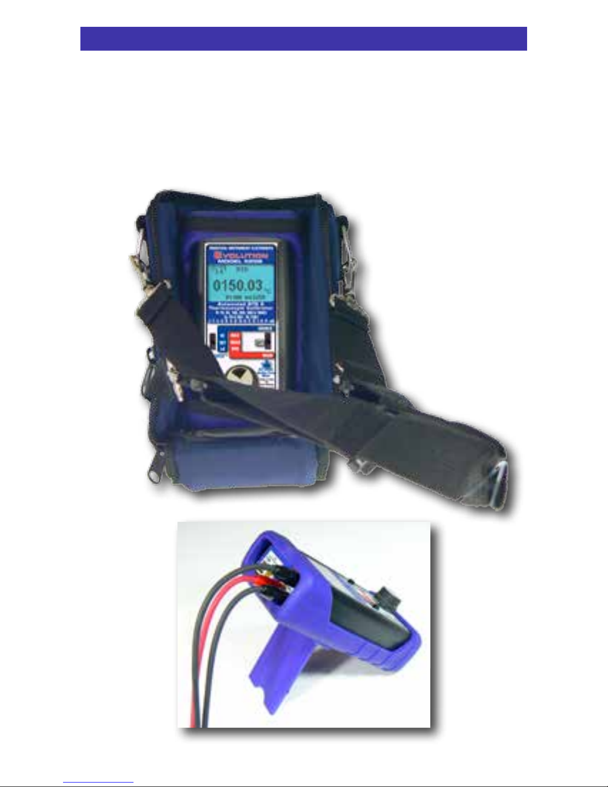
Operating Instructions
FIELD & BENCH USE
PIE 525B comes with a carrying case designed for hands-free
operation and a rubber boot with a built-in tilt stand. The PIE
525B is held in the case by elastic straps for use with the
carrying case open. The tilt stand is easily raised by pulling the
stand until it locks into place.

Page 7
Operating Instructions
STORING HI and LO EZ-CHECK Source Outputs
Speed up your calibration by storing Span & Zero output setting
for instant recall with the EZ-CHECK switch.
1) Store your high (SPAN) output temperature by moving the
EZ-CHECK switch to the HI position and turning the EZ-Dial
knob until the desired output value is on the display. Press
and hold the EZ-Dial knob until STORED appears to store
the value. Release the EZ-Dial knob.
2) Store your low (ZERO) output value by moving the EZ-CHECK
switch to the LO position and turning the EZ-Dial knob until
the desired output value is on the display. Press and hold the
EZ-Dial knob until STORED appears to store the value.
Release the EZ-Dial knob.
3) Instantly output your SPAN and ZERO output settings by
moving the EZ-CHECK switch between HI and LO. You may
also select any third output setting (such as mid-range) using
the SET position on the EZ-CHECK switch.
CHANGING BATTERIES
Low battery is indicated by a battery symbol on the display.
Approximately one to four hours of typical operation remain before
the PIE 525B will automatically turn off. To change the batteries
remove the rubber boot and remove the battery door from the
back of the unit by sliding the door downward. This allows access
to the battery compartment. Replace with four (4) “AA” 1.5V
batteries being careful to check the polarity. Replace the battery
door and replace the boot. All stored configuration options (T/C
Type, EZ-CHECK Memories, etc.) are reset to factory settings
when the batteries are removed.
Note: Alkaline batteries are supplied and recommended for
typical battery life and performance. Optional rechargeable
batteries (charged externally) are available.

Page 8
HI
TYPE K
22.4°C
43.307mV
°C
1052.50
T/C
+
-
Automated RTD &
Thermocouple Calibrator
Pt 10, 50, 100, 200, 500 & 1000Ω
Cu 10 & 50Ω · Ni 120Ω
J · T · E · K · R · S · B · N · G · C · D · L· U · P · mV
SOURCE
HI
SET
LO
OFF
MAX
READ
MIN
READ
OVERLOAD
Double Click
Menu
Push & Turn
for
Fast Dialing
Push & Hold
to
Store/Step
q EZ-CHECK™ SWITCH
SOURCE: Instantly output two preset settings by moving the
EZ-CHECK™ switch to the “LO” position or “HI” position.
For fast
three point checks select the “SET” position. The PIE 525B will
remember the last “SET” value, even with the power off.
These values can easily be changed to suit the calibration requirements.
The values stored in the HI and LO positions are also used for Auto
Stepping.
READ: Slide the switch to the SET position. The PIE 525B will display
the current reading from the sensor or device being measured. Slide
the switch to MAX and the highest value measured since turn-on or
reset will be displayed; slide the switch to MIN and the lowest value
measured since turn-on or reset will be displayed.
Operating Instructions
Basic Operation

Page 9
w SOURCE/OFF/READ Switch
Select “SOURCE” to output mV, T/C, Ω or RTD.
Select “READ” to read mV, T/C, Ω or RTD.
Select “OFF” to turn off the 525B.
e EZ-DIAL™ KNOB
SOURCE: Turn the knob to adjust the output level. Turn clockwise to
increase the output, counter clockwise to decrease the output in one
least significant digit step at a time. Push down and turn the
EZ-DIAL knob for faster dialing.
Press and hold the knob for two seconds to store desired
EZ-Check™ HI/LO points in SOURCE mode. Continue to press and
hold the knob for two more seconds to start the automatic ramping.
READ: Press and hold to transfer the current temperature into
the EZ-Check™ MIN/MAX points. This clears the MIN/MAX
readings which will update as the input value changes.
SELECTING FUNCTIONS
The EZ-DIAL knob is used to setup the PIE 525B to match the
instrument to be calibrated or signal to be measured. Each time
you turn on the PIE 525B the LCD displays the following screen
for about 1 second followed by operating in the function used the
last time it was operated.
Double Click the EZ-DIAL knob to change the function of the
calibrator and to select ranges, units and other user settings.
Each function (mV, T/C, Ohms, RTD) has up to three pages of
menus. The first menu page has settings for the function and the
last menu page has settings for STEPPING, AUTO OFF and
BACKLIGHT. Settings are remembered even with the power off
but are reset when the batteries are changed.
PIE 525B
DOUBLE CLICK
EZ-DIAL KNOB
FOR CONFIGURATION
Operating Instructions
Basic Operation

Page 10
Operating Instructions
Double Click Menus - MAIN Page
>EXIT (1/3)
FUNCTION V
RANGE 80mV
Double click the EZ-DIAL knob to access the Double Click
Menus. Shown are the MAIN menus for each function. Turn the
knob to scroll thru the menus and press the knob to select. Default
values are in black and available choices are shown in grey.
>EXIT (1/3)
FUNCTION V
RANGE 80mV
Source V
Read V
>EXIT (1/3)
FUNCTION T/C
UNITS °C °F
T/C TYPE J K E T R S B N L U G C D P
COLD JUNC ON OFF
>EXIT (1/3)
FUNCTION RTD
UNITS °C °F
RTD Pt 100 a=3850 [*RTD Types - See Read RTD]
>EXIT (1/3)
FUNCTION RTD
UNITS °C °F
RTD Pt 100 a=3850,
Pt 200 a=3850, Pt 500 a=3850,
Pt 1000 a=3850, Pt 100 a=3902, Pt 100 a=3916,
Pt 100 a=3926, Cu 10 a=4274, Cu 50 a=4280, Ni 120 a=6720
Pt 10 a=3850, Pt 50 a=3850
Source & Read Thermocouples
Source RTD
Read RTD
>EXIT (1/3)
FUNCTION OHMS
RANGE 400Ω 4000Ω
>EXIT (1/3)
FUNCTION OHMS
RANGE 400Ω 4000Ω
Source Ohms
Read Ohms
 Loading...