


Page 1
Copyright © 2016 All rights reserved • 235-9002 - Rev C 30 March 2016
PIE Model 235
Process Voltage Calibrator
Operating Instructions
PIE Model 235
Process Voltage Calibrator
Operating Instructions
• Technician friendly operation
Intuitive EZ-DIAL Double Click Menu makes it easier to setup than other calibrators. Turn on
the backlight to easily see the display in dark areas of the plant. Connections diagrams are
indicated on the display for each function along with a labeled connector panel on the top.
• Calibrate with Confidence
Accurate to ±0.02% of Reading + 0.01% Full Scale.
Out of range or over current is indicated by an
audible alarm, flashing display and the
OVERLOAD LED will light.
• Source three ranges of mV & V dc plus percent
of 1 to 5 volts
With the 235 you can check, calibrate and
measure all your voltage, millivolt and pH signal
instruments in your plant. Source -500.00 to
999.00 mV, 1.000 to 5.000 V, 0.0 to 100.0% of 1
to 5 V; 0.000 to 20.000 V.
• Power your loops with over 1,000 Ohm loads
The 20.000 V range has an extended span of up
to 24.000 Volts giving you a portable source for
powering your loops.
• Read DC volts
The 235 can measur
e from -500.00 to +999.00 mV,
0.000 to 5.000 V, 0.0 to 100.0 % of 1 to 5 V; 0 to
20.000 V and 0.00 to 60.00 V DC. Use it to check
loop power supplies, I/V converters, 1 to 5 Volt
signals, and other voltages.
• Save time calibrating recorders and monitors
in 4 to 20 mA loops
Other brands of calibrators require that you break
the loop to calibrate voltage inputs. With the PIE 235
you simply clip the test leads across the voltage inputs
in a live 4 to 20 mA loop without disconnecting any
wires.
• Simulate pH probes into transmitters & analyzers
Use the pH simulator to verify proper operation of pH devices
before you place a probe into a calibrated buffer.
• Quickly set any three outputs plus automatic stepping & ramping
Easily set any value with the adjustable “DIAL” plus store any three output settings for instant recall with
the EZ-CHECK™ switch. 2, 3, 5 & 11 steps automatically increment output in 100%, 50%, 25% or 10% of
span plus continuous ramp. Set step/ramp time to 5, 6, 7, 8, 9, 10, 15, 20, 25, 30 & 60 seconds.
• Designed for you by experienced calibrator manufacturers
PIE Calibrators are designed and built by members of the same team that designed and built the
calibrators manufactured by Fluke* under the Altek* label. The 235 improves upon other brands by
including a rubber boot, backlit display with larger digits, higher accuracy and more ranges for flexibility.
www. .com
information@itm.com1.800.561.8187

Page 2
LO
V
2 1
1.000
+
-
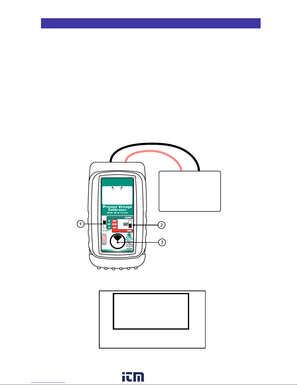
q EZ-CHECK™ SWITCH
SOURCE: Instantly output two preset voltages by
moving the EZ-CHECK™ switch to the “LO” position
or “HI” position.
For fast three point checks select
the “SET” position. The PIE Model 235 will
remember the last “SET” value, even with the
power off.
These values can easily be changed to suit the
calibration requirements. The values stored in the HI
and LO positions are also used for Auto Stepping.
READ: Slide the switch to the SET position. The PIE
Model 235 will display the current voltage from the
process output. Slide the switch to HI and the highest
voltage measured since turn-on or reset will be
displayed; slide the switch to LO and the lowest
voltage measured since turn-on or reset will be
displayed.
w SOURCE/OFF/READ Switch
Select “SOURCE” to output in volts, millivolts, %
of 1 to 5 Volts or pH.
Select “READ” to read volts or millivolts. Select
“OFF” to turn the unit off.
e EZ-DIAL™ KNOB
SOURCE: Turn the knob to adjust the output
level. Turn clockwise to increase the output,
counter clockwise to decrease the output in
0.001 V, 0.01 mV, 0.1% or 0.001 pH steps at a
time. Push down and turn the EZ-DIAL knob for
faster dialing.
Press and hold the knob for two seconds to store
desired EZ-Check™ HI/LO points in SOURCE
mode. Continue to press and hold the knob for
two more seconds to start the automatic
stepping or ramping.
READ: Press and hold to transfer the current
temperature into the EZ-Check™ HI/LO points.
This clears the HI/LO voltage readings which will
update as the input signal changes.
Double click the knob to get into the PIE Model
235 Configuration Mode. Use configuration to
select voltage or pH, Range, Backlight On/Off,
Step Size, Step Time and Auto Off On/Off.
CHANGING BATTERIES
Low battery is indicated by a battery symbol on
the display. Approximately one to four hours of
typical operation remain before the PIE Model
235 will automatically turn off. To change the
batteries; remove the rubber boot, remove the
battery door from the back of the unit by sliding
the door downward. This allows access to the
battery compartment. Replace with four (4) “AA”
1.5V batteries being careful to check the polarity.
Replace the battery door and replace the boot. All
stored configuration options (Range, EZ-CHECK
Memories, etc.,) are reset to factory settings
when the batteries are removed.
Note: Alkaline batteries are supplied and
recommended. Purchase the optional Ni-MH
rechargeable batteries for maximum battery life.
Basic Operation
The PIE Model 235 has two banana jacks
mounted in the top end of the housing.
Connections
2
-
+
1
www. .com
information@itm.com1.800.561.8187

Page 3
Configuration
Configure the Calibrator
Move w POWER SWITCH to “SOURCE” or
“READ”.
Setup
Double click the
e DIAL KNOB at any time the
unit is on and the following displays will appear
for 15 seconds:
Turn the
e DIAL KNOB to move through the two
pages of menus. Press the e DIAL KNOB to
toggle between OFF and ON or to scroll through
the settings.
EXIT - exits this menu immediately and saves
any changes. Menu will automatically exit after
15 seconds of inactivity).
FUNCTION - pressing the knob will toggle
between V and pH.
RANGE - pressing the knob will cycle through
the Voltage ranges of 20V, 5V, 999mV and 60V.
UNITS - pressing the knob will toggle between V
and % only in the 5 V RANGE. The 5 V RANGE
is preset with EZ-CHECK LO and HI at 1.000
(0.0%) and 5.000 V (100.0%).
DOUBLE CLICK
EZ-DIAL KNOB
FOR CONFIGURATION
V#.##
AUTO OFF - If AUTO OFF is ON, the unit will
turn off after 30 minutes of inactivity to save
battery life. If AUTO OFF is OFF the unit will stay
on until the POWER SWITCH is moved to the off
position.
BACKLIGHT - If BACKLIGHT is ON the
backlight will light all the time the unit is powered
up. For maximum battery life turn the backlight
off when using the calibrator in areas with
enough ambient light to read the display.
STEPS/RAMP - pressing the knob will cycle
through 2, 3, 5, 11 and RAMP. The endpoints of
the steps or ramp are based on the values
stored in the HI and LO EZ-CHECK outputs.
2 steps will automatically switch between the
values stored in the HI & LO EZ-CHECK (0 &
100%).
3 steps between the HI, Midpoint and LO
EZ-CHECK (0, 50 & 1
00%).
5 steps between the HI and LO EZ-CHECK
in 25% increments (0, 25, 50, 75 & 100%).
11 steps between the HI and LO EZ-CHECK
in 10% increments (0, 10, 20...80, 90 &100%).
RAMP continuously ramps up and down
between the HI and LO EZ-CHECK outputs.
STEP/RAMP TIME - pressing the knob will cycle
through 5, 6, 7, 8, 9, 10, 15, 20, 25, 30 and 60
seconds.
Note: All settings are remembered even with the
power off. Removing the batteries resets the
values to factory defaults.
MAIN
> EXIT (1/2)
FUNCTION V (pH only in SOURCE)
RANGE
20V 5V, 999mV, (60V READ Only)
UNITS V % (Only in 5V RANGE)
FEATURES
> EXIT (2/2)
AUTO OFF ON OFF
BACKLIGHT ON OFF
STEPS/RAMP 2 3 5 11 RAMP
STEP/RAMP TIME 5 6 7 8 9 10 15 20 25 30 60
(STEP/RAMP settings only in SOURCE)
www. .com
information@itm.com1.800.561.8187

Page 4
SOURCE
Choose this function to provide an output from -500.00 to 999.00 mV, from 0.000 to 20.000 V, from
1.000 to 5.000 V or from 0.0% to 100.0% of 1 to 5 Volts. The source current is a nominal 20 mA to
provide the driving power to your voltage receivers.
Move the power switch
w to SOURCE then Double Click the EZ-DIAL knob to get into the Menu.
Turn the knob to scroll through the settings and press the knob to make your selection. Select V for
the FUNCTION and 999 mV, 20 V or 5 V for the RANGE.
Connect the output leads of the PIE Model 235 to the inputs of the device being calibrated, making
sure to check polarity. Red lead to the plus (+) input and black lead to the minus (-) input.
Instantly output your SPAN and ZERO output settings by moving the EZ-CHECK switch between HI
and LO. You may also select any third output setting (such as mid-range) using the SET position on
the EZ-CHECK switch. The output is adjusted in 0.001 V, 0.01 mV or 0.1% increments by turning the
knob
e. Press and turn the knob for faster dialing with 0.100 V, 1.00 mV or 10.0% increments.
The red OVERLOAD indicator will light, a beeper will sound, and the display will flash if excessive
voltage or current is detected by the calibrator.
Sourcing DC Volts & Millivolts
Voltage Receiver Input
Controller
Transmitter
Computer
Recorder or Logger
DCS
2 1
+
-
HI
5.000V
www. .com
information@itm.com1.800.561.8187

Page 5
To change the Automatic Stepping settings
Double click the e DIAL KNOB at any time the unit is on and the menu will appear for 15 seconds.
Turn the e DIAL KNOB to move through down
to the second (FEATURES) menu. Press the e
DIAL KNOB to toggle between OFF and ON or
to change the STEPS and the STEP TIME
settings. These settings are remembered even
with the power off.
EXIT MENU - exits this menu immediately and saves any changes. Menu will automatically exit after
15 seconds of inactivity.
STEPS - pressing the knob will cycle through 2, 3, 5 and 11 then reverse direction. The endpoints of
the steps are based on the values stored in the HI and LO EZ-CHECK outputs.
2 steps will automatically switch between the values stored in the HI & LO EZ-CHECK (0 &
100%).
3 steps between the HI, Midpoint and LO EZ-CHECK (0, 50 & 100%).
5 st
eps between the HI and LO EZ-CHECK in 25% increments (0, 25, 50, 75 & 100%).
11 steps between the HI and LO EZ-CHECK in 10% increments (0, 10, 20...80, 90 &100%).
RAMP continuously between the HI and LO EZ-CHECK.
STEP TIME - pressing the knob will cycle through 5, 6, 7, 8, 9, 10, 15, 20, 25, 30 and 60 seconds.
To start the Automatic Stepping
Start automatic stepping or ramping by placing the EZ-CHECK Switch into the HI or LO position
then press and hold the
e DIAL KNOB for 6 seconds (the word STORE will appear on the display
after 3 seconds and continue to press the DIAL KNOB) until the word STEP appears on the display.
The word STEP will appear on the display anytime the selected automatic function is running. Stop
the stepping by again pressing and holding the
e DIAL KNOB for 3 seconds.
Automatic Stepping
Storing EZ-CHECK Outputs
STORING HI and LO EZ-CHECK Outputs
Choose this function to quickly toggle between HI and LO signals into controllers, transmitters,
recorders or any other input device that measure DC Voltages.
1) Store your high (SPAN) output voltage by moving the EZ-CHECK switch to the HI position and
turn the
e EZ-Dial knob until the desired voltage is on the display. Press and hold the EZ-Dial
knob until STORED appears to store the value. Release the EZ-Dial knob.
2) Store your low (ZERO) output voltage by moving the EZ-CHECK switch to the LO position and
turn the
e EZ-Dial knob until the desired voltage is on the display. Press and hold the EZ-Dial
knob until STORED appears to store the value. Release the EZ-Dial knob.
3) Instantly output your SPAN and ZERO voltage outputs by moving the EZ-CHECK switch between
HI and LO. You may also select any third voltage output (such as mid-range) using the SET position on the EZ-CHECK switch.
FEATURES
> EXIT (2/2)
AUTO OFF ON OFF
BACKLIGHT ON OFF
STEPS/RAMP 2
3 5 11 RAMP
STEP/RAMP TIME 5 6 7 8 9 10 15 20 25 30 60
www. .com
information@itm.com1.800.561.8187
Page 6
Signals exceeding ±60.00 VDC are indicated
by i on the display.
READ i
60.00 V
Read
Choose this function to measure from -500.00 to +999.00 mV, 0.000 to 20.000 V, 1.000 to 5.000 V,
0.0% to 100.0% of 1 to 5 Volts or 0.00 to 60.00 V.
Move the power switch
w to READ then Double Click the EZ-DIAL knob to get into the Menu. Turn
the knob to scroll through the settings and press the knob to make your selection. Select V for the
FUNCTION and 999 mV, 5 V, 20 V or 60 V for the RANGE.
Connect the red input lead (+) of the PIE Model 235 to the more positive point of the break and the
black input to the more negative point.
The PIE Model 235 measures the input signal and constantly updates the display with the current
reading. Move the EZ-CHECK switch
q to MAX to see the highest reading and to MIN to see the
lowest reading. Press and hold the knob e to clear the MAX and MIN readings.
Signals above the maximum scale are limited by protection circuitry with “OVER RANGE” flashed on
the display and the red OVERLOAD LED lit.
Reading DC Voltages
Voltage Output Signal
Controller
Transmitter
Power Supply
2 1
+
-
MAX
4.985 V
www. .com
information@itm.com1.800.561.8187

Page 7
pH SOURCE
Choose this function to provide an output from 0.000 to 14.000 pH @ 25°C (77°F) which corresponds
to 414.12 to -414.12 mV. BASE, NEUTRAL or ACID is indicated on the display. The source current is
a nominal 20 mA to provide the driving power to your pH receivers.
Move the power switch
w to SOURCE then Double Click the EZ-DIAL knob to get into the Menu.
Turn the knob to scroll through the settings and press the knob to make your selection. Select pH for
the FUNCTION.
Connect the output leads of the PIE Model 235 to the inputs of the device being calibrated, making
sure to check polarity. Red lead from the mV (+) jack of the Model 235 to the plus (+) input and black
lead from the mV (-) jack to the minus (-) input.
Instantly output your SPAN and ZERO output settings by moving the EZ-CHECK switch between HI
and LO. You may also select any third output setting (such as mid-range) using the DIAL position on
the EZ-CHECK switch. The output is adjusted in 0.001 pH increments by turning the knob
e. Press
and turn the knob for faster dialing with 0.100 pH increments.
The red OVERLOAD indicator will light, a beeper will sound, and the display will flash if excessive
voltage or current is detected by the calibrator.
pH Receiver Input
Controller
Transmitter
Analyzer
2 1
+
-
ACID
4.010pH
Simulate pH probes into transmitters & analyzers
Use the pH simulator to verify proper operation of pH devices before you place a probe into a
calibrated buffer. Adjusting the pH transmitter or analyzer without a probe allows you to make sure
the device is calibrated and operating correctly. The PIE Model 235 simulates 0.000 to 14.000 pH
@ 25°C corresponding to 414.12 to -414.12 mV.
Sourcing pH
Once the pH instrument has been adjusted against the PIE Model
235 reconnect the pH probe and check it against the proper buffer
(typically 7 pH). If the instrument zero point requires more than the
manufacturer’s recommendations (typically within 0.5 pH) it is time to
clean or replace the probe.
www. .com
information@itm.com1.800.561.8187

Page 8
Transmitter
input signal at
50% of Span
Transmitter
regulating
current to
12.00 mA
Loop
Power
Supply
12.00 mA
250Ω
mA
IN
Calibrate 1 to 5 V instruments in live 4 to 20 mA loops
Calibrate 1 to 5 volt instruments without breaking the loop or turning off the loop current. You do not need to
remove any 250 Ohm resistors. The PIE Model 235 drives only the voltage instrument it is connected to and
has no effect on any other instruments in the 4 to 20 mA loop.
Control loop with the transmitter limiting the current to 12.00 mA.
The recorder indicates 12.00 mA.
This loop has a recorder monitoring the 4 to 20 mA signal
Transmitter
input signal at
50% of Span
Transmitter
regulating
current to
12.00 mA
Loop
Power
Supply
4.00 mA
250Ω
mA
IN
Calibrating the recorder monitoring the 4 to 20 mA signal
Control loop with the transmitter limiting the current to 12.00 mA.
The 235 sourcing 1V is clipped across the mA input driving the recorder to
4.00 mA. The rest of the instruments in the loop are still seeing 12.00 mA.
www. .com
information@itm.com1.800.561.8187

Page 9
Hands free carrying case
with pockets for the PIE
235 & test leads.
Designed to be worn
around your neck so that
you can safely use both
hands to calibrate.
Flip out stand for bench use
www. .com
information@itm.com1.800.561.8187

Page 10
General
Operating Temperature Range -20 to 60 °C (-5 to 140 °F)
Storage Temperature Range -30 to 60 °C (-22 to 140 °F)
Relative Humidity Range 10 % ≤RH ≤90 % (0 to 35 °C), Non-condensing
10 % ≤RH≤ 70 % (35 to 60 °C), Non-condensing
Common Mode Rejection 50/60 Hz, 100 dB
Normal Mode Rejection 50/60 Hz, 50 dB
Noise ≤ ± ½ Least Significant Digit from 0.1 to 10 Hz
Size 5.63 x 3.00 x 1.60 inches, 143 x 76 x 41 mm (L x W x H)
Weight 12.1 ounces, 0.34 kg (including boot & batteries)
Batteries Four “AA” Alkaline 1.5V (LR6)
Battery Life
≥ 50 hours
Low Battery
Low battery indication with nominal 1 hour of operation left
Protection against misconnection Over-voltage protection to 60 vrms (rated for 30 seconds). Red
LED and audible alarm indicates OVERLOAD for out of range
conditions.
Display High contrast graphic liquid crystal display with 0.35” (9 mm) high
digits on main & 0.2” (5 mm) on mA display. LED backlighting for
use in low lit areas.
Specifications subject to change without notice.
PIE 235 Specifications
(Unless otherwise indicated all specifications are rated from a nominal 23°C, 70% RH for 1 year from calibration)
www. .com
information@itm.com1.800.561.8187

Page 11
PIE 235 Specifications
(Unless otherwise indicated all specifications are rated from a nominal 23°C, 70% RH for 1 year from calibration)
pH Source
Accuracy in mV
Accuracy in pH
≤ ± (0.02 % of Reading in mV + 0.1 mV)
≤ ± 0.003 pH @ 25°C
Voltage Read
Range and Resolution
-500.00 to 999.00 mV
1.000 to 5.000 V
0.000 to 20.000 V
-25.0 to 125.0% of 1 to 5 V
0.00 to 60.00 V
Accuracy
≤ ± (0.02 % of Reading + 0.01% of Full Scale)
≤ ± (0.02 % of Reading + 0.002 V)
≤ ± (0.02 % of Reading + 0.01% of Full Scale)
≤ ± 0.1%
≤ ± (0.02 % of Reading + 0.02 V)
Input resistance ≥ 1 MΩ
Voltage Source
Ranges and Resolution
-500.00 to 999.00 mV
1.000 to 5.000 V
0.000 to 20.000 V
-25.0 to 125.0% of 1 to 5 V
Accuracy
≤ ± (0.02 % of Reading + 0.01% of Full Scale)
≤ ± (0.02 % of Reading + 0.002 V)
≤ ± (0.02 % of Reading + 0.01% of Full Scale)
≤ ± 0.1%
Source Current
≥ 20 mA
Sink Current > 16 mA
Output Impedance ≤ 0.3 Ohm at ≤ 20 mA load
Short Circuit Duration Infinite
www. .com
information@itm.com1.800.561.8187

Page 12
Warranty
Our equipment is warranted against defective material and workmanship (excluding batteries) for a
period of three years from the date of shipment. Claims under warranty can be made by returning
the equipment prepaid to our factory. The equipment will be repaired, replaced or adjusted at our
option. The liability of Practical Instrument Electronics (PIE) is restricted to that given under our
warranty. No responsibility is accepted for damage, loss or other expense incurred through sale or
use of our equipment. Under no condition shall Practical Instrument Electronics, Inc. be liable for any
special, incidental or consequential damage.
Additional Information
This product is calibrated on equipment traceable to NIST and includes a Certificate of Calibration.
Test Data is available for an additional charge.
Practical Instrument Electronics recommends a calibration interval of one year. Contact your local
representative for recalibration and repair services.
Ordering Information
Description Part No
PIE Model 235 Process Voltage Calibrator .......................... PIE Model 235
Included:
Four “AA” Alkaline batteries, NIST Traceable Calibration Card
Black Rubber Boot ....................................................................020-0209
Evolution Hands Free Carrying Case ..........................................020-0211
Evolution mA/V Test Leads ........................................................020-0207
1 Red & 1 Black Lead
with Banana Plugs & Alligator Clips
Optional
Certified Test Data when ordered new from the factory .............Certified Test Data-1
Three Year Repair/Replacement Warranty ..................................RP-WAR-A
Ni-MH 1 Hour Charger with 4 Ni-MH AA Batteries ....................020-0103
www. .com
information@itm.com1.800.561.8187
 Loading...