


 Loading...
Operator’s Manual
MM102341V1
Rev. F, Sep/06
M7100IP Series
Mobile Radio

|
|
MANUAL REVISION HISTORY |
|
|
|
REV |
DATE |
REASON FOR CHANGE |
A |
Feb/04 |
Initial release. |
B |
Apr/04 |
Added MPE and FCC information for VHF, UHF-L, UHF-H, and 800MHz M7100IP radios. |
C |
Jun/05 |
Added MPE, VHF maritime channel, and FCC information for 50W VHF mobile radio. Corrected P25 |
|
|
display information and added motorcycle MPE information for UHF, VHF, and 800 MHz radios. |
D |
Nov/05 |
Added P25 Trunked operation and Radio TextLink operation. |
E |
Feb/06 |
Added CE mark and EU automotive directive requirements. |
F |
Sep/06 |
Added 100W UHF MPE information and WEEE symbol and statement. Updated MPE tables by rounding |
|
|
distances to whole numbers safety symbols. |
|
|
|
M/A-COM Technical Publications would particularly appreciate feedback on any errors found in this document and suggestions on how the document could be improved. Submit your comments and suggestions to:
Wireless Systems Business Unit |
or fax your comments to: 1-434-455-6851 |
M/A-COM, Inc. |
|
Technical Publications |
or e-mail us at: techpubs@tycoelectronics.com |
221 Jefferson Ridge Parkway |
|
Lynchburg, VA 24501 |
|
Automotive Directive 72/245/EEC – 95/54/EC:
SUPPLEMENTARY INFORMATION
At this time, the M7100IP mobile radio may not be operated while in a desktop station in the European Community since it does not meet immunity requirements when operated in this mode. The M7100IP mobile radio can be used in both trunked and conventional applications.
ACKNOWLEDGEMENTS
This device is made under license under one or more of the following US patents: 4,590,473; 4,636,791; 5,148,482; 5,185,796; 5,271,017; 5,377,229; 4,716,407; 4,972,460; 5,502,767; 5,146,497; 5,164,986; 5,185,795.
The voice coding technology embodied in this product is protected by intellectual property rights including patent rights, copyrights, and trade secrets of Digital Voice Systems, Inc. The user of this technology is explicitly prohibited from attempting to decompile, reverse engineer, or disassemble the Object Code, or in any other way convert the Object Code into human-readable form.
The software contained in this device is copyrighted by M/A-COM, Inc. Unpublished rights are reserved under the copyright laws of the United States.
CREDITS
EDACS is a registered trademark and ProGrammer, SCAT, Failsoft, ProSound, ProScan, Aegis, ProFile, ProVoice, and G-STAR are trademarks of M/A-COM, Inc.
IMBE is a registered trademark of Digital Voice Systems, Inc. All other brand and product names are trademarks, registered trademarks, or service marks of their respective holders.
All other brand and product names are trademarks, registered trademarks, or service marks of their respective holders.
NOTICE!
This product conforms to the European Union WEEE Directive 2002/96/EC. Do not dispose of this product in a public landfill. This product should be taken to a recycling center at the end of its life.
This manual covers M/A-COM products manufactured and sold by M/A-COM, Inc.
Repairs to this equipment should be made only by an authorized service technician or facility designated by the supplier. Any repairs, alterations, or substitution of recommended parts made by the user to this equipment not approved by the manufacturer could void the user’s authority to operate the equipment in addition to the manufacturer’s warranty.
This manual is published by M/A-COM, Inc., without any warranty. Improvements and changes to this manual necessitated by typographical errors, inaccuracies of current information, or improvements to programs and/or equipment, may be made by M/A- COM, Inc., at any time and without notice. Such changes will be incorporated into new editions of this manual. No part of this manual may be reproduced or transmitted in any form or by any means, electronic or mechanical, including photocopying and recording, for any purpose, without the express written permission of M/A-COM, Inc.
Copyright© 2004-2006 M/A-COM, Inc. All rights reserved.
2

NOTICE!
This device is a RF transceiver intended for land mobile radio applications. This device may have use restrictions, which require that the national authority be contacted for any system licensing requirements, frequency use, allowable power level, etc.
3

|
TABLE OF CONTENTS |
|
|
|
Page |
1 |
SAFETY SYMBOL CONVENTIONS .......................................................................................... |
7 |
2 |
RF ENERGY EXPOSURE INFORMATION.............................................................................. |
8 |
2.1RF ENERGY EXPOSURE AWARENESS, CONTROL INFORMATION, AND OPERATION INSTRUCTIONS FOR FCC OCCUPATIONAL USE
|
|
REQUIREMENTS ...................................................................................................... |
8 |
|
2.2 |
COMPLIANCE WITH RF EXPOSURE STANDARDS ........................................... |
9 |
3 |
OPERATION SAFETY RECOMMENDATIONS .................................................................... |
13 |
|
|
3.1 |
TRANSMITTER HAZARDS ................................................................................... |
13 |
|
3.2 |
SAFE DRIVING RECOMMENDATIONS .............................................................. |
13 |
4 OPERATING RULES AND REGULATIONS .......................................................................... |
14 |
||
|
4.1 |
OPERATING TIPS ................................................................................................... |
14 |
5 |
MARITIME CHANNELS............................................................................................................ |
15 |
|
6 |
INTRODUCTION......................................................................................................................... |
16 |
|
7 |
USER INTERFACE...................................................................................................................... |
17 |
|
8 |
CONTROLS .................................................................................................................................. |
18 |
|
|
8.1 |
POWER ON - OFF VOLUME KNOB ....................................................................... |
18 |
|
8.2 |
SYSTEM/GROUP CHANNEL KNOB .................................................................... |
18 |
|
8.3 |
RAMP CONTROL .................................................................................................... |
18 |
|
8.4 |
SCAN ON/OFF ......................................................................................................... |
18 |
|
8.5 |
SCAN ADD/DELETE .............................................................................................. |
19 |
|
8.6 |
INDICATORS ........................................................................................................... |
19 |
|
8.7 |
KEYPAD ................................................................................................................... |
19 |
9 |
DISPLAY |
....................................................................................................................................... |
23 |
|
9.1 |
RADIO STATUS ICONS ......................................................................................... |
23 |
|
9.2 .............................................................................................................. |
MESSAGES |
24 |
10 |
ALERT TONES ............................................................................................................................ |
27 |
|
|
10.1 .................................................................................................. |
CALL ORIGINATE |
27 |
|
10.2 ................................................................ |
AUTOKEY (TRUNKED MODE ONLY) |
27 |
|
10.3 ........................................................ |
CALL QUEUED (TRUNKED MODE ONLY) |
27 |
|
10.4 ........................................................ |
SYSTEM BUSY (TRUNKED MODE ONLY) |
27 |
|
10.5 ......................................................... |
CALL DENIED (TRUNKED MODE ONLY) |
27 |
|
10.6 ................................................................................ |
CARRIER CONTROL TIMER |
27 |
|
10.7 ................................................................................................ |
KEY PRESS ALERT |
27 |
|
10.8 ............................................................................. |
DUAL CONTROL SWITCHING |
27 |
|
10.9 .............................................................................. |
PAGE (P25 TRUNKED ONLY) |
28 |
11 |
OPERATION................................................................................................................................. |
29 |
|
|
11.1 .................................................................................... |
TURNING THE RADIO ON |
29 |
|
11.2 ................................................................................... |
SELECTION MODE RULES |
29 |
|
11.3 .................................................................................................... |
DIRECT ACCESS |
30 |
4

|
TABLE OF CONTENTS |
|
|
|
Page |
11.4 |
MENU....................................................................................................................... |
30 |
11.5 |
FEATURE ENCRYPTION DISPLAY..................................................................... |
34 |
11.6 |
SYSTEM/GROUP/CHANNEL SELECTION ......................................................... |
36 |
11.7 |
LAST SYSTEM/GROUP/CHANNEL RECALL..................................................... |
37 |
12 TRUNKED MODE OPERATION.............................................................................................. |
38 |
|
12.1 |
RECEIVING A CALL.............................................................................................. |
38 |
12.2 |
SENDING A CALL.................................................................................................. |
38 |
12.3 |
CONVENTIONAL FAILSOFT (EDACS ONLY)................................................... |
38 |
12.4 |
EMERGENCY OPERATION .................................................................................. |
39 |
12.5 |
SYSTEM SCAN OPERATION................................................................................ |
39 |
12.6 |
GROUP SCAN OPERATION.................................................................................. |
41 |
12.7 |
INDIVIDUAL CALLS ............................................................................................. |
43 |
12.8 |
SCAT OPERATION................................................................................................. |
44 |
12.9 |
TELEPHONE INTERCONNECT CALLS .............................................................. |
45 |
12.10 |
MOBILE DATA ....................................................................................................... |
46 |
12.11 |
STATUS/MESSAGE OPERATION ........................................................................ |
49 |
12.12 |
EDACS CONVENTIONAL P1 SCAN .................................................................... |
50 |
12.13 |
DYNAMIC REGROUP OPERATION .................................................................... |
50 |
12.14 |
RADIO TEXTLINK OPERATION (EDACS ONLY)............................................. |
50 |
12.15 |
PAGE (P25 TRUNKED ONLY) .............................................................................. |
51 |
13 CONVENTIONAL MODE OPERATION................................................................................. |
52 |
|
13.1 |
RECEIVING A CALL.............................................................................................. |
52 |
13.2 |
SENDING A CALL.................................................................................................. |
52 |
13.3 |
EMERGENCY OPERATION .................................................................................. |
52 |
13.4 |
SCANNING CONVENTIONAL CHANNELS ....................................................... |
53 |
13.5 |
TURNING SCAN ON .............................................................................................. |
54 |
13.6 |
TURNING SCAN OFF............................................................................................. |
55 |
13.7 |
SQUELCH ADJUST ................................................................................................ |
55 |
13.8 |
TYPE 99 DECODE .................................................................................................. |
56 |
13.9 |
DIRECT MODE OPERATION................................................................................ |
57 |
13.10 |
LAST SCANNED CHANNEL RECALL ................................................................ |
57 |
14 PROJECT 25 (P25) CONVENTIONAL OPERATION............................................................ |
58 |
|
14.1 |
GROUP CALLS IN P25 MODE .............................................................................. |
58 |
14.2 |
INDIVIDUAL CALLS IN P25 MODE .................................................................... |
58 |
14.3 |
EMERGENCY GROUP CALLS IN P25 MODE..................................................... |
59 |
15 TRUNKED OR CONVENTIONAL MODE OPERATION ..................................................... |
60 |
|
15.1 |
SIREN/LIGHT OPERATION .................................................................................. |
60 |
15.2 |
DIGITAL VOICE OPERATION.............................................................................. |
60 |
15.3 |
DUAL CONTROL OPERATION ............................................................................ |
64 |
15.4 |
MULTIPLE RADIO OPERATION.......................................................................... |
65 |
5

|
TABLE OF CONTENTS |
|
|
|
Page |
15.5 |
MACRO KEY OPERATION.................................................................................... |
67 |
15.6 |
INTERCONNECT CALL (SYSTEM MODEL ONLY) .......................................... |
67 |
15.7 |
KEYPAD REMAPPING........................................................................................... |
67 |
GLOSSARY.......................................................................................................................................... |
|
69 |
RADIO SETUP .................................................................................................................................... |
|
71 |
WARRANTY........................................................................................................................................ |
|
77 |
6

1 SAFETY SYMBOL CONVENTIONS
The following conventions are used to alert the user to general safety precautions that must be observed during all phases of operation, service, and repair of this product. Failure to comply with these precautions or with specific warnings elsewhere violates safety standards of design, manufacture, and intended use of the product. M/A-COM, Inc. assumes no liability for the customer's failure to comply with these standards.
The WARNING symbol calls attention to a procedure, practice, or the like, which, if not correctly performed or adhered to, could result in personal injury. Do not proceed beyond a WARNING symbol until the conditions identified are fully understood or met.
The CAUTION symbol calls attention to an operating procedure, practice, or the like, which, if not performed correctly or adhered to, could result in a risk of danger, damage
to the equipment, or severely degrade the equipment performance.
CAUTION
The NOTE symbol calls attention to supplemental information, which may improve system performance or clarify a process or procedure.
The ESD symbol calls attention to procedures, practices, or the like, which could expose equipment to the effects of Electro-Static Discharge. Proper precautions must be taken to prevent ESD when handling circuit modules.
WARNING - The electrical hazard symbol indicates there is an electrical hazard present.
7
2RF ENERGY EXPOSURE INFORMATION
2.1RF ENERGY EXPOSURE AWARENESS, CONTROL INFORMATION, AND OPERATION INSTRUCTIONS FOR FCC OCCUPATIONAL USE REQUIREMENTS
Before using your mobile two-way radio, read this important RF energy awareness and control information and operational instructions to ensure compliance with the FCC’s RF exposure guidelines.
This radio is intended for use in occupational/controlled conditions, where users have full knowledge of their exposure and can exercise control over their exposure to meet FCC limits. This radio device is NOT authorized for general population, consumer, or any other use.
Changes or modifications not expressly approved by M/A-COM, Inc. could void the user's authority to operate the equipment.
CAUTION
This two-way radio uses electromagnetic energy in the radio frequency (RF) spectrum to provide communications between two or more users over a distance. It uses RF energy or radio waves to send and receive calls. RF energy is one form of electromagnetic energy. Other forms include, but are not limited to, electric power, sunlight, and x-rays. RF energy, however, should not be confused with these other forms of electromagnetic energy, which, when used improperly, can cause biological damage. Very high levels of x- rays, for example, can damage tissues and genetic material.
Experts in science, engineering, medicine, health, and industry work with organizations to develop standards for exposure to RF energy. These standards provide recommended levels of RF exposure for both workers and the general public. These recommended RF exposure levels include substantial margins of protection. All two-way radios marketed in North America are designed, manufactured, and tested to ensure they meet government established RF exposure levels. In addition, manufacturers also recommend specific operating instructions to users of two-way radios. These instructions are important because they inform users about RF energy exposure and provide simple procedures on how to control it. Please refer to the following websites for more information on what RF energy exposure is and how to control your exposure to assure compliance with established RF exposure limits.
http://www.fcc.gov/oet/rfsafety/rf-faqs.html http://www.osha.gov./SLTC/radiofrequencyradiation/index.html
2.1.1Federal Communications Commission Regulations
Your M/A-COM, Inc. M7100IP mobile two-way radio is designed and tested to comply with the FCC RF energy exposure limits for mobile two-way radios before it can be marketed in the United States. When two-way radios are used as a consequence of employment, the FCC requires users to be fully aware of and able to control their exposure to meet occupational requirements. Exposure awareness can be facilitated by the use of a label directing users to specific user awareness information. Your M/A-COM, Inc. M7100IP two-way radio has an RF exposure product label. Also, your M7100IP Installation and Operator’s Manuals include information and operating instructions required to control your RF exposure and to satisfy compliance requirements.
8

2.2COMPLIANCE WITH RF EXPOSURE STANDARDS
Your M/A-COM, Inc. M7100IP mobile two-way radio is designed and tested to comply with a number of national and international standards and guidelines (listed below) regarding human exposure to RF electromagnetic energy. This radio complies with the IEEE and ICNIRP exposure limits for occupational/controlled RF exposure environment at duty factors of up to 50% talk-50% listen and is authorized by the FCC for occupational use. In terms of measuring RF energy for compliance with the FCC exposure guidelines, your radio antenna radiates measurable RF energy only while it is transmitting (talking), not when it is receiving (listening) or in standby mode.
Your M/A-COM, Inc. M7100IP mobile two-way radio complies with the following RF energy exposure standards and guidelines:
•United States Federal Communications Commission (FCC), Code of Federal Regulations; 47 CFR §§ 2 sub-part J.
•American National Standards Institute (ANSI)/Institute of Electrical and Electronic Engineers (IEEE) C95.1-1992.
•Institute of Electrical and Electronic Engineers (IEEE) C95.1-1999.
Table 2-1 lists the recommended minimum lateral distance for a controlled environment and for unaware bystanders in an uncontrolled environment, from transmitting types of antennas (i.e., monopoles over a ground plane, or dipoles) at rated radio power for mobile radios installed in a vehicle. Transmit only when unaware bystanders are at least
CAUTION the uncontrolled recommended minimum lateral distance away from the transmitting antenna.
Table 2-1: Rated Power and Recommended Minimum Lateral Distance (Vehicle-Installed)
|
MOBILE RADIO |
|
|
RATED POWER OF |
|
|
RECOMMENDED MINIMUM LATERAL |
|
|
FREQUENCY |
|
|
VEHICLE-INSTALLED |
|
|
DISTANCE FROM TRANSMITTING ANTENNA |
|
|
SPLIT |
|
|
MOBILE TWO-WAY RADIO |
|
|
CONTROLLED |
UNCONTROLLED |
|
VHF |
|
110 Watts |
|
93 cm |
208 cm |
||
|
|
(Antenna P/N: 19B209568P6) |
|
|||||
|
|
|
|
|
|
|
||
|
VHF |
|
50 Watts |
|
64 cm |
142 cm |
||
|
|
(Antenna P/N: AN102800V1/V2) |
|
|||||
|
|
|
|
|
|
|
||
|
UHF–L |
|
50 Watts |
|
58 cm |
130 cm |
||
|
378-430 MHz |
|
(Antenna P/N: AN102800V1) |
|
||||
|
|
|
|
|
||||
|
UHF-H |
|
50 Watts |
|
47 cm |
104 cm |
||
|
450-512 MHz |
|
(Antenna P/N: AN102800V1) |
|
||||
|
|
|
|
|
||||
|
UHF-H |
|
100 Watts |
|
72 cm |
162 cm |
||
|
450-470 MHz |
|
(Antenna P/Ns: AN102800V1, |
|
|
|
||
|
|
|
|
AN-025158-001, AN-025158-005, |
|
|
|
|
|
|
|
|
AN-025158-009, AN-025158-011) |
|
|
|
|
|
800 MHz |
|
35 Watts |
|
33 cm |
73 cm |
||
|
|
(Antenna P/N: AN102800V1) |
|
|||||
|
|
|
|
|
|
|
||
9

2.2.1Mobile Antennas – Vehicle Installation
Install the radio’s antenna (refer to Table 2-1 for applicable antenna part numbers) in the center of the vehicle’s roof. These mobile antenna installation guidelines are limited to metal body motor vehicles or vehicles with appropriate ground planes. The antenna installation should additionally be in accordance with the following.
•The requirements of the antenna manufacturer/supplier included with the antenna.
•Instructions in the M7100IP Radio Installation Manual, including minimum antenna cable lengths.
•The installation manual providing specific information of how to install the antennas to facilitate recommended operating distances to all potentially exposed persons.
Use only the M/A-COM approved/supplied antenna(s) or approved replacement antenna. Unauthorized antennas, modifications, or attachments could damage the radio and may violate FCC regulations.
Radios intended for motorcycle installations are factory-configured at 25 watts. It is important that radios not intended for motorcycle installations are not substituted for
motorcycle radio units.
CAUTION
Table 2-2 lists the recommended minimum lateral distance for a controlled environment and for unaware bystanders in an uncontrolled environment, from transmitting types of antennas (i.e., monopoles over a ground plane, or dipoles) at rated radio power for mobile radios installed on a motorcycle. Transmit only when unaware bystanders are at
CAUTION least the uncontrolled recommended minimum lateral distance away from the transmitting antenna.
10
Table 2-2: Rated Power and Recommended Minimum Lateral Distance (Motorcycle-Installed)
MOBILE RADIO |
RATED POWER OF |
RECOMMENDED MINIMUM LATERAL |
|
FREQUENCY |
MOTORCYCLE-INSTALLED |
DISTANCE FROM TRANSMITTING ANTENNA |
|
SPLIT |
MOBILE TWO-WAY RADIO |
CONTROLLED |
UNCONTROLLED |
VHF |
25 Watts, (136 MHz, Antenna |
54 cm |
121 cm |
|
P/N: SM-LE-OM150K.125/TNC) |
|
|
UHF–L |
25 Watts, (378 MHz, Antenna |
54 cm |
122 cm |
|
P/N: LE-OM406BKTNC) |
|
|
|
25 Watts, (378 MHz, Antenna |
51 cm |
115 cm |
|
P/N: LE-OM420BKTNC) |
|
|
UHF-H |
25 Watts, (450 MHz, Antenna |
50 cm |
111 cm |
|
P/N: LE-OM440BKTNC) |
|
|
|
25 Watts, (450 MHz, Antenna |
50 cm |
111 cm |
|
P/N: LE-OM450BKTNC) |
|
|
|
25 Watts, (450 MHz, Antenna |
49 cm |
109 cm |
|
P/N: LE-OM470BKTNC) |
|
|
|
25 Watts, (450 MHz, Antenna |
48 cm |
106 cm |
|
P/N: LE-OM490BKTNC) |
|
|
800 MHz |
35 Watts, (806 MHz, Antenna |
48 cm |
107 cm |
|
P/N: LE-OM806DBKTNCDS) |
|
|
2.2.2Mobile Antennas – Motorcycle Installation
This device must not be co-located or operating in conjunction with any other antenna or transmitter.
Install the radio’s antenna (refer to Table 2-2 for frequencies and corresponding part numbers of recommended antennas) on the end of the motorcycle case farthest away from the driver. These mobile antenna installation guidelines are limited to motorcycles fit with the motorcycle radio case with integral antenna grounding plane. The antenna installation should additionally be in accordance with the following.
•The requirements of the antenna manufacturer/supplier included with the antenna.
•Instructions in the M7100IP Radio and Control Unit Motorcycle Installation Manual, including minimum antenna cable lengths.
•The installation manual providing specific information of how to install the antennas to facilitate recommended operating distances to all potentially exposed persons.
Use only the M/A-COM approved/supplied antenna(s) or approved replacement antenna(s). Unauthorized antennas, modifications, or attachments could damage the radio and may violate FCC regulations.
2.2.3Approved Accessories
This radio has been tested and meets the FCC RF guidelines when used with the M/A-COM accessories supplied or designated for use with this product. Use of other accessories may not ensure compliance with the FCC’s RF exposure guidelines, and may violate FCC regulations.
For a list of M/A-COM approved accessories refer to the product manuals, M/A-COM’s Products and Services Catalog, or contact M/A-COM at 1-800-368-3277.
11
2.2.4Contact Information
For additional information on exposure requirements or other information, contact M/A-COM, Inc. at 1-800-528-7711 or at http://www.macom-wireless.com.
12

3OPERATION SAFETY RECOMMENDATIONS
3.1TRANSMITTER HAZARDS
The operator of any mobile radio should be aware of certain hazards common to the operation of vehicular radio transmitters. A list of several possible hazards is given:
•Heat Dissipation – When the M7100 mobile is used for an extended period time in transmit mode, the heat sink fins on top of the mobile chassis may be uncomfortable to the touch. Please exercise caution when handling or working near the mobile when it is in use.
•Explosive Atmospheres – Just as it is dangerous to fuel a vehicle with the motor running, similar hazards exist when operating a mobile radio. Be sure to turn the radio off while fueling a vehicle. Do not carry containers of fuel in the trunk of a vehicle if the radio is mounted in the trunk.
Areas with potentially explosive atmosphere are often, but not always, clearly marked. Turn OFF your radio when in any area with a potentially explosive atmosphere. It is rare, but not impossible that the radio or its accessories could generate sparks.
•Interference to Vehicular Electronics Systems – Electronic fuel injection systems, electronic antiskid braking systems, electronic cruise control systems, etc., are typical electronic systems that can malfunction due to the lack of protection from radio frequency energy present when transmitting. If the vehicle contains such equipment, consult the dealer and enlist their aid in determining the expected performance of electronic circuits when the radio is transmitting.
•Electric Blasting Caps – To prevent accidental detonation of electric blasting caps, DO NOT use two-way radios within 1000 feet of blasting operations. Always obey the “Turn Off Two-Way Radios” signs posted where electric blasting caps are being used. (OSHA Standard: 1926-900)
•Liquefied Petroleum (LP) Gas Powered Vehicles – Mobile radio installations in vehicles powered by liquefied petroleum gas with the LP gas container in the trunk or other sealed-off space within the interior of the vehicle must conform to the National Fire Protection Association standard NFPA 58 requiring:
o The LP gas container and its fittings.
o Outside filling connections shall be used for the LP gas container. o The LP gas container shall be vented to the outside of the vehicle.
3.2SAFE DRIVING RECOMMENDATIONS
(Recommended by AAA)
•Read the literature on the safe operation of the radio.
•Keep both hands on the steering wheel and the microphone in its hanger whenever the vehicle is in motion.
•Place calls only when the vehicle is stopped.
•When talking from a moving vehicle is unavoidable, drive in the slower lane. Keep conversations brief.
•If a conversation requires taking notes or complex thought, stop the vehicle in a safe place and continue the call.
•Whenever using a mobile radio, exercise caution.
13

4 OPERATING RULES AND REGULATIONS
Two-way FM radio systems must be operated in accordance with the rules and regulations of the local, regional, or national government.
In the United States, the M7100IP Series mobile radio must be operated in accordance with the rules and regulations of the Federal Communications Commission (FCC). As an operator of two-way radio equipment, you must be thoroughly familiar with the rules that apply to your particular type of radio operation. Following these rules helps eliminate confusion, assures the most efficient use of the existing radio channels, and results in a smoothly functioning radio network.
When using your two-way radio, remember these rules:
•It is a violation of FCC rules to interrupt any distress or emergency message. As your radio operates in much the same way as a telephone “party line,” always listen to make sure that the channel is clear before transmitting. Emergency calls have priority over all other messages. If someone is sending an emergency message – such as reporting a fire or asking for help in an accident – KEEP OFF THE
AIR!
•The use of profane or obscene language is prohibited by Federal law.
•It is against the law to send false call letters or false distress or emergency messages. The FCC requires that you keep conversations brief and confine them to business. To save time, use coded messages whenever possible.
•Using your radio to send personal messages (except in an emergency) is a violation of FCC rules. You may send only those messages that are essential for the operation of your business.
•It is against Federal law to repeat or otherwise make known anything you overhear on your radio. Conversations between others sharing your channel must be regarded as confidential.
•The FCC requires that you identify yourself at certain specific times by means of your call letters. Refer to the rules that apply to your particular type of operation for the proper procedure.
•No changes or adjustments shall be made to the equipment except by an authorized or certified electronics technician.
Under U.S. law, operation of an unlicensed radio transmitter within the jurisdiction of the United States may be punishable by a fine of up to $10,000, imprisonment for up to two
(2)years, or both.
4.1OPERATING TIPS
The following conditions tend to reduce the effective range of two-way radios and should be avoided whenever possible:
•Operating the radio in areas of low terrain, or while under power lines or bridges.
•Obstructions such as mountains and buildings.
•In areas where transmission or reception is poor, some improvement can be obtained by moving a few yards in another direction or moving to a higher elevation.
14

5 MARITIME CHANNELS
As part of FCC Equipment Authorization Part 80 licensing a maritime frequency usage plan has been included in this manual for reference.
15
6 INTRODUCTION
This manual describes how to use the M7100IP Series Mobile Radio. The M7100IP is a synthesized, microprocessor-based, high performance mobile FM radio providing reliable two-way communications in the Enhanced Digital Access Communications System (EDACS®) and P25 Trunking environments, as well as, conventional communication systems.
In the EDACS or P25 Trunked system mode, the user selects a communications system and group. In this mode, channel selection is transparent to the user and is controlled via digital communication with the system controller. This provides advanced programmable features and fast access to communication channels.
In the conventional mode, the user selects a channel and directly communicates on that channel. In this mode, a system refers to a set of channels. A channel is a transmit/receive radio frequency pair.
The exact operation of the radio will depend on the operating mode, the radio's programming and the particular radio system. Most features described in this manual can be enabled or disabled through
programming. Consult the system administrator for the particular features that are programmed into the M7100IP.
16
7 USER INTERFACE
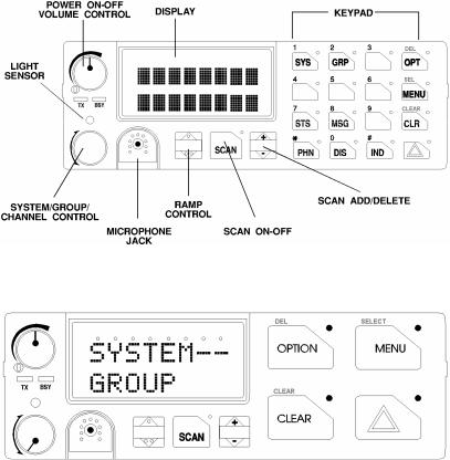
The M7100IP operating controls are located on the radio's front panel (see Figure 7-1and Figure 7-2). A keypad, vacuum florescent display for radio status information and a microphone jack are on the front panel. The front panel also provides a rotary SYSTEM/GROUP/CHANNEL knob, POWER ONOFF/VOLUME control, a ramp up/ramp down control, Scan add/delete control, and a SCAN ON-OFF control for scan operation.
The keypad is used for manual number entry for individual calls, access to a telephone interconnect system and activation of various EDACS, P25 Trunked, or conventional features such as menu selection. Each key has an associated LED for status indication.
The display has two lines with eight alphanumeric-characters used to show the operational mode of the radio. There is one LED for indicating transmitter ON and one LED to indicate CHANNEL BUSY located below the POWER ON-OFF/VOLUME Control.
Figure 7-1: M7100IP Series Mobile Radio System Model Front Panel
Figure 7-2: M7100IP Series Mobile Radio Scan Model Front Panel
17

8 CONTROLS
This section describes the buttons, keys and rotary knobs used to control the M7100IP Series Mobile Scan and System Model radios. All functions and controls of the Scan radio operate the same as the corresponding functions and controls on the System radio. The Scan radio is equipped with a 4-button keypad and the System radio is equipped with a 16-button keypad.
Many of the control buttons and keys have been or can be programmed to have a primary function and a secondary function. The SCAN button can be programmed (as a secondary function) to toggle the keypad keys between their primary function and their secondary function.
8.1POWER ON-OFF VOLUME KNOB
This rotary knob powers the radio ON and OFF and adjusts the receiver volume. Rotating the control clockwise out of detent applies power to the radio. A single alert tone sounds (if enabled through programming) to indicate the radio is operational.
Rotating the control clockwise increases the volume level. Minimum volume levels can be programmed into the radio to prevent missed calls due to a low volume setting. While adjusting the volume, the display will briefly indicate the volume level (i.e. VOL = 31). The volume range is from a minimum level of zero (displayed as OFF in the display) up to 31, which is the loudest level.
8.2SYSTEM/GROUP CHANNEL KNOB
This rotary switch selects the systems or groups/channels, depending upon programming. This 16-position rotary switch has no stop or detent. See SYSTEM/GROUP/CHANNEL SELECTION section for more details.
8.3RAMP CONTROL
The primary function of this rocker type button is to scroll through the System list or the Group/Channel list depending upon programming. The secondary function is to increment or
decrement items within a list (phone list for example). Press ,to scroll in increasing order and press .to scroll in decreasing order. To auto-ramp, press and hold the button.
8.4SCAN ON/OFF
The primary function of this button is to toggle scan operation ON and OFF. When the radio is scanning, the SCAN LED is on and all groups or channels in the scan list of the currently selected systems are scanned.
The secondary function of the SCAN button is to toggle the keypad buttons between their primary function and their secondary function.
18

8.5SCAN ADD/DELETE
This rocker type button is used to display the current SCAN status for a group/channel and then either add or delete the group/channel from the system scan list.
Pressing the add/delete button twice while the radio is actively receiving or three times when the radio is not receiving selects the last scanned channel (Last Scanned Channel Recall).
8.6INDICATORS
Transmitter enabled - ON when the radio is transmitting.
BuSY - Indicates a carrier is being received (the channel is busy). Note that if the selected channel is programmed for Channel Guard (CG), Digital Channel Guard (DCG) or Type 99 (T99) tone decode operation, the radio will not un-squelch if a valid tone or code is not received; the BSY indicator will be on.
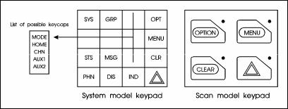
Figure 8-1: M7100IP System Model Keypad
Figure 8-2: M7100IP Scan Model Keypad
8.7KEYPAD
The keypad is similar to a telephone keypad but with four (4) additional buttons on the side for a total of 16 keys. In addition to numbers (1-9, *, 0 and #), which is a secondary function, most of the keys have or can be programmed to have a primary function. A symbol or abbreviated word describing its primary function is labeled on the keycap. Each labeled keycap is associated with a radio feature (or primary function). The radio must be programmed to operate with the Standard or the Optional keycap configuration.
19
A keylight (LED) is associated with each key or button. This can light when the associated function is active. In some conditions, the keylight can blink to indicate an action status.
The keypad key functions can be remapped to any of the primary function keys using the PC programming software. It is suggested that the blank keypad (located at the back of this manual) be completed if the keypad key functions are changed.
8.7.1Standard Keycap Configuration
The Standard keycap package for the System radio includes five (5) labeled keycaps (MODE, HOME, CHN, AUX1 and AUX2) and six (6) blank keycaps, which can be placed on any of the five key locations (numbers 3-6 and 9) shown in Figure 8-3. The keycap represents the primary function programmed for that key location. See Section 8.7.3 for a description of the primary function associated with these five (5) keycaps.
The standard keycap package for the Scan radio includes five (5) labeled keycaps [MENU, CLEAR, SELECT, EMERGENCY E or “E,” and OPTION] and five (5) blank keycaps, which can be placed on any of the four (4) keypad keys. The keycap represents the primary function programmed for that key location.
Figure 8-3: Standard M7100IP Keycaps Configuration
8.7.2Optional Keycap Configuration
The optional keycap package for the System radio includes sixty (60) additional keycaps (shown in Section 8.7.3), which can be placed on any key location desired. Keep in mind, the keycap represents the primary function programmed for that key location.
8.7.3Key Descriptions
MODE |
This key is used to enter the Conventional System selection mode. |
HOME |
This key returns the radio to the Home System/Group where it is programmed. |
CHN |
This key is used to enter the Channel select mode. |
AUX1 & 2 |
These keys are used to control output 1 or 2. Their definition is PC programmable. |
S |
This key is used to enter the System select mode. |
g |
This key is used to enter the Group select mode. |
o |
The “OPT” or “OPTION” key is used to toggle a PC programmable feature ON |
or |
and OFF. |
O |
|
20
DEL Secondary function - used to delete a digit during numeric entry (see Section 11.2).
MPrimary function - accesses the menu list. This is a list of additional features that are not available directly from the keypad. See Section 11.4 for details.
SELECT Secondary function - activates a selected item within a list. After the menus list is
accessed, select a menu item from the list via RAMP controls, , or ., and activate it with this key. Once activated, MENU continues its secondary function for activating a selected parameter setting until the radio returns to its normal receive state. This is similar to an enter key.
sThe Status key permits the transmission of a pre-programmed status message to an EDACS or P25 Trunked site.
nThe Message key permits the transmission of a pre-programmed message to an EDACS or P25 Trunked site.
cServes several purposes depending on the operating mode. In trunked mode, the CLR button exits the current operation and removes all displays associated with it. The radio and display then return to the group receive state. In Conventional
Cmode, pressing this button unmutes the receiver so activity on the selected channel can be monitored. When pressed and held for approximately 3 seconds, this button toggles conventional channel decoding (Channel Guard, Digital Channel Guard, T99) ON and OFF if programmed for the selected channel.
pUsed to place telephone calls through the radio by selecting the interconnect special call function. See TELEPHONE INTERCONNECT CALLS for details.
d |
Used to adjust the current display intensity and the keypad backlight level. |
iUsed to call an individual or make an all-call by selecting the individual call function. See INDIVIDUAL CALLS for details.
E |
The Emergency key is used to declare emergencies. |
or |
|
ALM |
This key toggles the external alarm ON/OFF. The external alarm is used to |
|
indicate the radio is receiving an Individual Call. Press the key once to enable |
|
external alarm and press again to disable external alarm. |
SG1-SG5 |
This key corresponds to five (5) pre-programmed System/Groups. Pressing a key |
|
programmed for SG1 would switch the radio to the pre-programmed |
|
System/Group 1. Pressing a key programmed for SG2 would switch the radio to |
|
the pre-programmed System/Group 2, etc. |
WAIL, YLP, |
The WAIL and YLP (Yelp) keys are designed to control an optional Siren |
RST, SL1- |
package. The SL1-SL8 (Siren/Light) keys are designed to control an optional |
SL8 |
Siren/Light package. The RST (Reset) key is used to turn all sirens and lights |
|
OFF. |
SPK |
This key function is used to toggle the external speaker ON/OFF. |
21
STO-ST9 |
The status 0-9 keys are used to send a pre-programmed status message to the |
|
EDACS or P25 Trunked site. |
PVT |
The PVT key enables or disables Private Mode for the System/Group displayed. |
|
See the Private Operation section. |
KEY |
Displays the Encrypted Keys. This selects the DISP KEY operation from the |
|
menu functions. |
G* |
This key function is used in Conventional Mode to send G-STAR emergency |
|
signaling. |
PA |
This key function enables and disables the Public Address feature. |
# |
DTMF keypad function. |
1 thru 9 |
Keypad numbers. |
*DTMF Keypad function.
8.7.4Primary Functions (Quick Access)
The secondary function of the kbutton is to toggle the keypad buttons between their primary function and their secondary function. When the secondary keypad is active, i.e. entering phone
digits for an interconnect call, the kbutton can be used to toggle the keypad buttons back to their primary function, perform a task (siren/light enable), and then toggle back to finish entering
the digits for the phone number. PRIMARY is displayed when the kbutton is used to toggle the keypad keys back to their primary functions. This provides quick access to the primary
functions of the keypad. This is a programmable feature of the kbutton only. Careful consideration should be given to possible operational conflicts before enabling this feature.
Several keys on the Scan version have a secondary function. The mkey is the SELECT secondary function with the Ckey remaining the same for the secondary function. On the
System version, the ohas a secondary function for DELETE, mis SELECT, and c retains its CLEAR function.
22

9 DISPLAY
The radio's display is shown in Figure 9-1. The two character lines are used to display system, group and channel names, and also operational messages. Each line contains eight alphanumeric character blocks. See Figure 7-2 for a typical display.
Figure 9-1: M7100IP Series Mobile Radio Display
9.1RADIO STATUS ICONS
Status icons are indicators that show the various operating characteristics of the radio. The icons appear on the first line of the display.
•indicates selected group or channel is in scan list.
•indicates selected group or channel is programmed as Priority 1 in scan list.
•indicates selected group or channel is programmed as Priority 2 in scan list.
• indicates conventional channel enabled with Channel Guard function.
•indicates the EDACS or P25 Trunked system is in Failsoft™ mode (if enabled through programming).
• indicates Type 99 Decode is enabled on a conventional channel.
23
9.2MESSAGES
During radio operation, various messages are displayed on either line 1 or line 2. Typical messages include control channel status information, such as system busy or call denied, or messages associated with the radio's operation, (i.e. volume adjust). These messages are described as follows:
|
|
Table 9-1: Display Messages |
|
|
|
MESSAGE |
NAME |
DESCRIPTION |
QUEUED |
Call Queued |
Trunked mode only. Indicates the system has placed the call in a request queue. |
SYS BUSY |
System Busy |
Trunked mode only. Indicates the system is busy, no channels are currently |
|
|
available, the queue is full or an individual call is being attempted to a radio that is |
|
|
currently transmitting. |
DENIED |
Call Denied |
Trunked mode only. Indicates the radio is not authorized to operate on the selected |
|
|
system. |
CC SCAN |
Control Channel Scan |
Trunked mode only. Indicates the control channel is lost and the radio has entered |
|
|
the Control Channel Scan mode to search for the control channel. |
WA SCAN |
Wide Area Scan |
Trunked mode only. Indicates the control channel is lost and the radio has entered |
|
|
the Wide Area Scan mode to search for a new system (if enabled through |
|
|
programming). |
|
|
|
TALKARND |
Talk-around |
Conventional mode only. Indicates the radio is operating on conventional channels |
|
|
in talk-around mode (no repeater). |
*RXEMER* |
Receive Emergency |
Trunked mode only. Indicates an emergency call is being received. This message |
|
|
will be flashing on line 2. |
*TXEMER* |
Transmit Emergency |
Trunked mode only. Indicates an emergency call has been transmitted. This |
|
|
message will be flashing on line 2. |
VOL=31 |
Volume Level |
Indicates the current volume level. The volume level display ranges from OFF |
|
|
(silent) to 31 (loudest). |
UNKNOWN |
Caller's ID Not |
Indicates that an individual call is being received, but the caller's ID was not |
|
Received |
received. |
TX DATA |
Transmit Data |
Trunked mode only. Indicates the radio is transmitting a data call. |
RX DATA |
Receive Data |
Trunked mode only. Indicates the radio is receiving a data call. Displayed on line 2. |
DATA OFF |
Data OFF |
Trunked mode only. Indicates the radio is in the data disabled state. Displayed on |
|
|
line 1. |
DATA ON |
Data ON |
Trunked mode only. Indicates the radio has been toggled to the data enable state. |
|
|
Displayed for two seconds on line 1 when toggled to enable state. |
SYSC ON |
System Scan Features |
Trunked mode only. Indicates the System Scan features are enabled. |
|
ON |
|
SYSC OFF |
System Scan Features |
Trunked mode only. Indicates the System Scan features are disabled. |
|
OFF |
|
T99 ON |
Type 99 Decode ON |
Conventional mode only. Indicates the Type 99 Decode feature is enabled. |
T99 OFF |
Type 99 Decode OFF |
Conventional mode only. Indicates the Type 99 Decode feature is disabled. |
PA ON |
Public Address ON |
Indicates that the public address function of the radio is enabled. |
PA OFF |
Public Address OFF |
Momentary (2 seconds) indicates that public address function of the radio was |
|
|
disabled. |
ALRM ON |
External Alarm Enabled |
Indicates that the external alarm function of the radio is enabled. |
ALRM OFF |
External Alarm |
Momentary (2 seconds) indicates that the external alarm function of the radio was |
|
Disabled |
disabled. |
PVT DIS |
Private Mode Disabled |
Indicates that private mode is disabled or no encryption key has been programmed |
|
|
for the selected group/channel or special call. |
FRCD PVT |
Forced Private |
Indicates that forced private operation has been pre-programmed into radio. |
|
Operation |
|
|
|
|
24
Loading...