

Page 1
V: 2.1
T
Spec
ru
PICO MACOM INC, U.S.A.
CAM-35UNIV
™
®
AUDIO/VIDEO
MODULATOR
NTSC
PICO MACOM INC.
Installation
And
Operation
Manual
Doc. No. OM2032N-2 REV.A
Date: 4/4/99
12500 Foothill Blvd., Lakeview Terrace, CA 91342 • (818) 897-0028 • (800) 421-6511 • FAX (818) 834-7197
Page 2
SAFEGUARDS
Importent Information
Product Inspection
Inspect the equipment for shipping damage.
Should any damage be discovered, immediately file
a claim with the carrier.
WARNING
HAZARD, DO NOT EXPOSE THIS APPLIANCE TO RAIN OR MOISTURE.
CAUTION
RISK OF ELECTRIC SHOCK
DO NOT OPEN
–
FOR INDOOR USE ONLY. TO PREVENT FIRE OR SHOCK
Important Safety Instructions
To insure proper installation and operation, take a moment to read this guide before
proceeding with the installation. If you have
any questions or comments about the CAM-
35UNIV modulator, please contact your dealer
or have him contact the PICO MACOM Service Center at the phone numbers at the bottom of the page.
WARNING: TO REDUCE THE RISK OF FIRE OR ELECTRIC SHOCK, DO NOT EXPOSE
THIS APPLIANCE TO RAIN OR MOISTURE. DO NOT OPEN THE CABINET,
REFER SERVICING TO QUALIFIED PERSONNEL ONLY.
CAUTION: TO PREVENT ELECTRIC SHOCK DO NOT USE THIS (POLARIZED) PLUG
WITH AN EXTENSION CORD RECEPTACLE OR OTHER OUTLET UNLESS
THE BLADES CAN BE FULLY INSERTED TO PREVENT BLADE EXPOSURE.
The lightning flash with arrowhead symbol, within an equilateral triangle, is intended to alert the user to the presence of
uninsulated "dangerous voltage" within the product's enclosure that may be of sufficient magnitude to constitute a risk of
electric shock to persons.
The exclamation point within an equilateral triangle is intended to alert the user to the presence of important operating
and maintenance (servicing) instructions in the literature
accompanying the appliance.
ATTENCION: POUR PREVENIR LES CHOCS ELECTRIQUES, NE PAS UTILISER CETTE
FICHE POLARISEE AVEC UN PROLONGATEUR, UNE PRISE DE COURANT
OU UNE AUTRE SORTIE DE COURANT, SAUF SI LES LAMES PEUVENT
ETRE INSEREES A FOND SANS EN LAISSER AUCUNE PARTIE A
DECOUVERT.
1. Read Instructions - All safety and operating instructions should
be read before the appliance is operated.
2. Retain Instructions - The safety and operating instructions
should be retained for future reference.
3. Heed Warnings - All warnings on the appliance should be
adhered to.
4. Follow Instructions - All operating and user instructions should
be followed.
5. Cleaning - Unplug this appliance from the wall outlet before
cleaning. Use a damp cloth for cleaning. Do not use liquid cleaners
or aerosol cleansers.
6. Do Not Use Attachments - not recommended by the manufacturer or they may cause hazards.
7. Water and Moisture - Do not use this product near water - for
example, near a bathtub, washbowl, kitchen sink, laundry tub, in a
wet basement, or near a swimming pool - and the like.
8. Accessories - Do not place this product on an unstable cart, stand,
tripod, bracket, or table. The product may fall, causing serious injury
to a child or adult, and serious damage to the appliance.
9. Ventilation - This video product should never be placed near or
over a radiator or heat register. This video product should not be
placed in a built-in installation such as a bookcase or rack unless
proper ventilation is provided or the manufacturer’s instructions
have been adhered to. Any slots or opening in the cabinet are
provided for ventilation. To ensure reliable operation of the video
product and to protect it from overheating, these openings must not
be blocked or covered. The openings should never be blocked by
placing the product on a bed, sofa, rug, or other similar surface.
1
PICO MACOM INC.
12500 Foothill Blvd., Lakeview Terrace, CA 91342 • (818) 897-0028 • (800) 421-6511 • FAX (818) 834-7197
Page 3
Importent Information con't
10. Grounding or Polarization - This video product is equipped
with a polarized alternating - current line plug (a plug having one
blade wider than the other). This plug will fit into the power socket
only one way. This is a safety feature. If you are unable to insert the
plug full into the outlet, try reversing the plug. If the plug should still
fail to fit, contact your electrician to replace your obsolete outlet.
Do not defeat the safety purpose of the polarized plug.
11. Power Sources - This product should be operated only from the
type of power source indicated on the marking label. If you are not
sure of the type of power supplied to your home, consult your
appliance dealer or local power company.
12. Power-cord Protection - Power-supply cords should be routed
so they are not likely to be walked on or pinched by items placed
upon or against them. Pay particular attention to cords and plugs,
convenience receptacles, and the point where they exit from the
appliance.
13. Lightning - For added protection for this product during a
lightning storm, or when it is left unattended or unused for long
periods of time, the unit should be disconnected.
14. Power Lines - An outside antenna system should not be located
in the vicinity of overhead power lines, other electric light or power
circuits, where it can fall into such power lines or circuits. When
installing an outside antenna system, extreme care should be taken
to keep from touching power lines or circuits as contact with them
may be fatal.
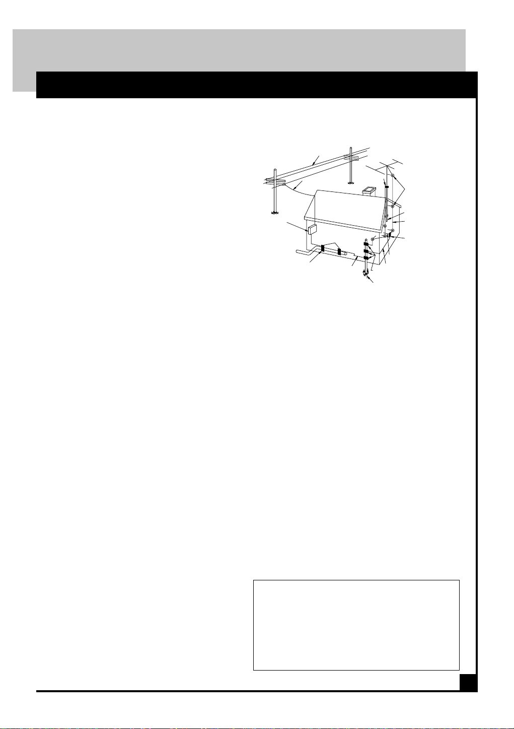
SAFEGUARDS
EXAMPLE OF ANTENNA GROUNDING ACCORDING TO
NATIONAL ELECTRICAL CODE INSTRUCTIONS CONTAINED
IN ARTICLE 810 - "RADIO AND TELEVISION
EQUIPMENT"
POWER LINES
SERVICE ENTRANCE
CONDUCTORS
SERVICE
ENTRANCE
EQUIPMENT
G
R
POWER SERVICE GROUNDING
ELECTRODE SYSTEM
(e.g. interior metal water pipe)
BONDING JUMPER
19. Replacement Parts - When replacement parts are required, be sure the
service technician has used replacement parts specified by the manufacturer or have the same characteristics as the original parts. Unauthorized
substitutes may result in fire, electric shock or other hazards.
20. Safety Check - Upon completion of any service or repairs to this
product, ask the service technician to perform safety checks to
determine that the product is in proper operating conditions.
GROUND CLAMP
O
U
N
D
C
L
A
M
P
S
d
GROUND CLAMPS
OPTIONAL ANTENNA GROUNDING ELECTRODE
DRIVEN 8 FEET (2.44M) INTO THE EARTH
IF REQUIRED BY LOCAL CODES. SEE NEC
SECTION 810 - 21(f).
STANDOFF
INSULATORS
MAST
ANTENNA
LEAD-IN WIRE
ANTENNA
DISCHARGE UNIT
TO EXTERNAL ANTENNA
TERMINALS OF PRODUCT
GROUND WIRE
b
c
15. Overloading - Do not overload wall outlets and extension cords
as this can result in risk of fire or electric shock.
16. Object and Liquid Entry - Never push objects of any kind into
this product through openings as they may touch dangerous voltage
points or short-out parts that could result in a fire or electric shock.
Never spill liquid of any kind on the product.
17. Servicing - Do not attempt to service this product yourself as
opening or removing covers may expose you to dangerous voltage
or other hazards. Refer all servicing to qualified service personnel.
18. Damage Requiring Service - Unplug this product from the wall
outlet and refer servicing to qualified service personnel under the
following conditions:
a. When the power-supply cord or plug is damaged.
b. If liquid has been spilled, or objects have fallen into the product.
c. If the product has been exposed to rain or water.
d. If the product does not operate normally by following the
operating instruction. Adjust only those controls that are covered by
the operating instructions. An improper adjustment may result in
damage and will often require extensive work by a qualified technician to restore the product to its normal operation.
e. If the product has been dropped or the cabinet has been damaged.
f. When the product exhibits a distinct change in performance - this
indicates a need for service.
21. Outdoor Antenna Grounding - Before attempting to install this
product, be sure the antenna or cable system is grounded so as to
provide some protection against voltage surges and built-up static
charges.
a. Use No.10 AWG (5.3mm ) copper, No.8 AWG (8.4mm (aluminum, No.7 AWG (10mm ) copper-clad steel or bronze wire or larger,
as ground wire.
b. Secure antenna lead-in and ground wires to house with stand-off
insulators spaced from 4 feet (1.22m) to 6 feet (1.83m) apart.
c. Mount antenna discharge unit as close as possible to where leadin enters house.
d. A driven rod may be used as the grounding electrode where other
types of electrode systems do not exist. Refer to the National
Electrical Code, ANSI/NFPA 70-1984 for information.
e. Use jumper wire not smaller than No.6 AWG (13.3mm ) copper
or equivalent, when a separate antenna grounding electrode is used.
NOTE TO THE CATV SYSTEM INSTALLER:
THIS REMINDER IS PROVIDED TO CALL THE CATV
SYSTEM INSTALLER’S ATTENTION TO ARTICLE 820 40 OF THE NEC THAT PROVIDES GUIDELINES FOR
PROPER GROUNDING AND, IN PARTICULAR, SPECIFIES THAT THE CABLE GROUND SHALL BE CONNECTED TO THE GROUNDING SYSTEM OF THE BUILDING, AS CLOSE TO THE POINT OF CABLE ENTRY AS
PRACTICAL.
2
PICO MACOM INC.
12500 Foothill Blvd., Lakeview Terrace, CA 91342 • (818) 897-0028 • (800) 421-6511 • FAX (818) 834-7197
Page 4
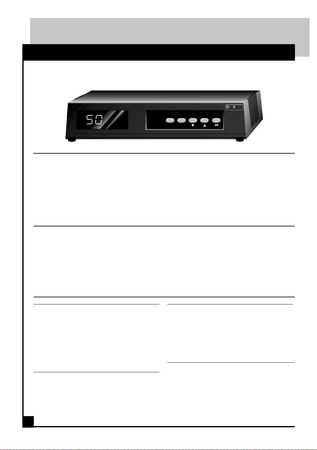
D E S C R I P T I O N
and Specifications
CAM-35UNIV
Consumer Agile Modulator
CAM-35UNIV
Features
• Excellent picture quality
• Microprocessor controlled PLL with
user selectable output channel
• Tunes to UHF channels 14 through 69
• Tunes to CATV channels 37 through 125
• Minimum 35dBmV output
CH.
OFFSET
MODE
• Low spurious harmonic output
• HRC and IRC offset capable.
• Retains channel memory even after loss of
power
• Attractive low profile consumer converter
case
™
•
®
pec
u
CATV/TVCHANNEL
PICO MACOM INC., U.S.A.
Description
The CAM-35UNIV modulates a video and Left
& Right audio signal of a VCR, satellite receiver
or security camera to a user selected TV channel.
The modulator has a double sideband, 35 dBmV
output that is free from spurious distortions. The
microprocessor con-trolled Phase Lock Loop
(PLL) circuitry allow selection of the output
channel to be made from the front panel. The selected
Specifications
RF
Channels: UHF or Ultraband
Output Level: 35 dBmv minimum,
Output Impedance: 75 ohm
Audio/Video Ratio: pre-set -15 dB below
visual carrier
Frequency Stability: ±10 KHz,
Spurious Output: >55 dB below video
carrier (typical)
Video
Input Level: 1.0 V p-p min for 65 -
87.5% modulation
ModulationType: AM vestigual side band
positive/negative
Visual C/N: >55 dB
3
channel number is displayed in the channel selection
window. Non-volatile memory locks and holds the
selected channel in case of the loss of input power.
The agile design provides maximum flexibility while
allowing installers to maintain an inventory of only
two models to cover all NTSC channels. The CAM35UNIV also supports HRC and IRC offsets and BTSC
audio.
Audio
Input Impedance: 600 ohms unbalanced
Baseband Input
Output Format:
Pre-Emphasis: 75* microsecond
Flatness:
0.5 Vp-p for 25 KHz peak
deviation
BTSC (BTSC stereo capable)
2 dB max 50 Hz to 15 KHz
General
Power Input: 105 to 135 VAC, 60 Hz.
Operating Temperature :0°C to 50°C
Dimensions: 1 7/8" x 6 3/4" x 5 1/4"
Weight: 1.5 pounds
Connectors:
Input/Audio & Video RCA type
Output F type
Specifications subject to change without notice
PICO MACOM INC.
12500 Foothill Blvd., Lakeview Terrace, CA 91342 • (818) 897-0028 • (800) 421-6511 • FAX (818) 834-7197
Page 5
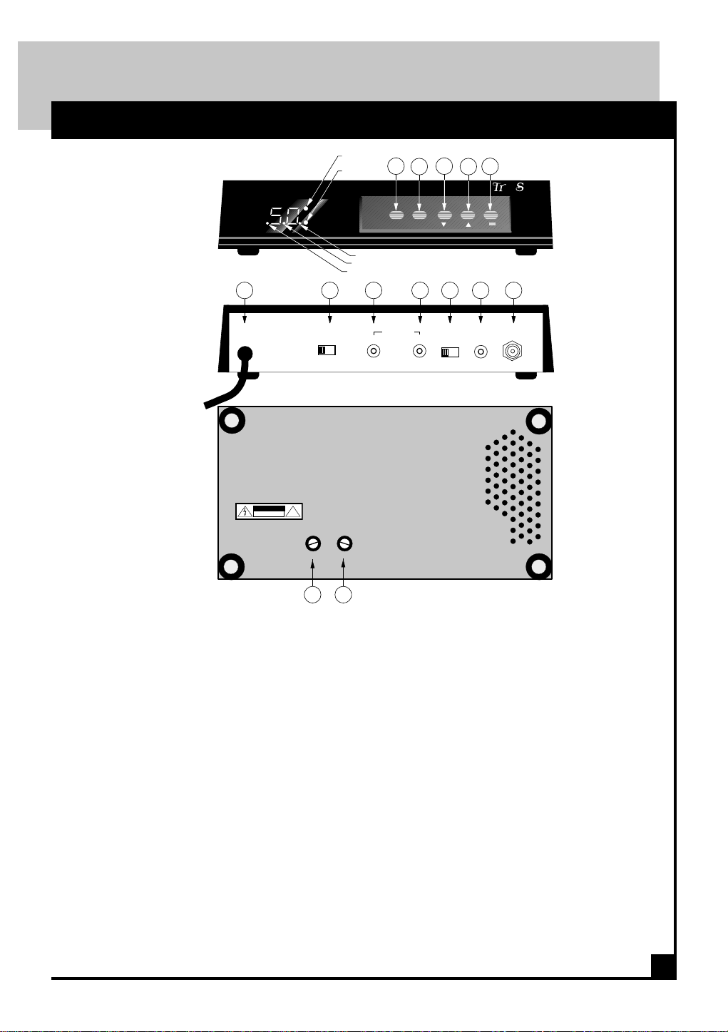
P A N E L S
Front & Rear Panels
Front Panel
Rear Panel
Bottom Panel
CAM-35UNIV
6 7
AC120V
60Hz
15W
+
CAUTION
RISK OF ELECTRIC SHOCK
!
DO NOT OPEN
VIDEO
ADJUST
DIP.
OFF ON
25kHz
1.25kHz
STD
HRC
IRC
12
OFFSET
345
CH
MODE
CHANNEL
8 9 10 11 12
AUDIO IN
L/B.B.
R
B.B.
ADJUST
L B.B.
VIDEO
IN
CATV/TV
u
RF
OUT
•
pec
PICO MACOM INC.
™
®
+
++
1. Offset:
Selects 12.5 or 25 kHz offset.
2. Ch. Mode:
Selects Standard, HRC or IRC frequencies. Set in
standard position unless your cable company re-
quires HRC or IRC offset.
3. Channel Select:
Press button to select lower channel number
4. Channel Select:
Press button to select higher channel number.
5. CATV/TV
Selects cable or off-air modes. "Dot" appears
on display when in CATV mode.
6. Power Cord:
Connect to 120 Vac, 60Hz electrical outlet.
7. Display on/off switch:
Set this switch to on to illuminate seven segment
display on front panel and to activate front panel
controls.
PICO MACOM INC.
12500 Foothill Blvd., Lakeview Terrace, CA 91342 • (818) 897-0028 • (800) 421-6511 • FAX (818) 834-7197
1413
8. Right Audio In:
Accepts a balanced audio output from satellite
receiver, VCR, cable converter, etc.
9. Left Audio and Baseband In:
Accepts a balanced audio output from satellite
receiver, VCR, cable converter, etc.
10. Left Audio/Base Band Select:
If stereo sound is desired a BTSC stereo generator
must be used. Set slide switch to B.B. and connect
left audio to the composite out of the generator.
See page 6.
11. Video Input:
Accepts video output from satellite receiver , VCR
or cable converter.
12. RF Out:
To TV or distribution system.
13. Video Adjust:
Used to set video modulation level. Adjust for
best picture.
14. B.B. Adjust:
Used to set audio modulation level.
Adjust for desired sound level.
4
Page 6

INSTALLATION
Installation Procedures
1. Electrical Connection:
Plug the power cord into 120 Vac, 60Hz electrical
outlet.
2. Video and Audio Input Connections:
a. Slide the rear display switch to the ON
position. This switch activates and deactivates
the digital display and the channel selector buttons on the front panel.
b. Connect in the audio and video plugs from
the input source to the AUDIO in and VIDEO in
jacks respectivily. For sources with only one
audio output, connect to either the right or left
jack.
c. Using the two front panel controls, select a
channel between 14 and 69 for off-air or 37 to
125 for CATV. NOTE: The modulator's LED
displays either off-air UHF or cable (CATV)
channels.
d. After selecting the channel, slide the rear
display switch, on rear panel, to the OFF position. This will disable the front panel tuning
controls and turn off the LED display. The
channel you have selected will be stored in
memory.
camcorder or surveillance camera to an
ultraband CATV channel or a standard UHF
channel.
4. Channel Selection Guidelines:
a. The CAM-35UNIV modulator converts your
input source to either UHF or Cable (CATV)
channels. Be sure your television set is tuned
properly for off-air or cable reception.
b. Do not select channels that are adjacent to a
CATV or an active off-air channel. In applications using multiple modulators, do not set modulators to adjacent channels, for example 20, 21,
22.
c. Do not select a channel on which a local TV
channel is being broadcast.
d. Caution: The lowest UHF frequencies, channels 14-19, have also been assigned as a commercial communications band. A nearby transmittercould cause intermittent interference on these
channels.
3. RF Output Connections:
The CAM-35UNIVan be used for various
applications to modulate a signal source such
as a satellite receiver, VCR, laser disk player,
TO DISTRIBUTION SYSTEM
AC120V
60Hz
15W
CAM-35UNIV
AUDIO OUT
R
Note: If mono receiver is used, audio may be
connected to either audio jack on CAM-35UNIV
DISPLAY
OFF ON
VIDEO
OUT
L
LEFT , RIGHT AUDIO OUT
5
PICO MACOM INC.
12500 Foothill Blvd., Lakeview Terrace, CA 91342 • (818) 897-0028 • (800) 421-6511 • FAX (818) 834-7197
AUDIO IN
L/B.B.
R
VIDEO OUT
5. Completion:
Once connections have been make and the desired channel has been selected, installation of
the CAM-35UNIV is complete.
RF
VIDEO
OUT
IN
L B.B.
FROM LNB
COMPOSITE
VIDEO OUT
SATELLITE RECEIVER
LNB
IN
Page 7

INSTALLATION
Stereo Hook-Up
Note: To obtain stereo sound the CAM-35UNIV must be used with a stereo encoder. T h e m ethod
of installation is shown below.
RF OUT (TO DISTRIBUTION SYSTEM)
VIDEO IN
BASE BAND SELECT SWITCH
AUDIO IN
CAM-35UNIV
CAM-35U/U
AC120V
60Hz
15W
DISPLAY
OFF ON
R
AUDIO IN
L/B.B.
L B.B.
VIDEO
IN
RF
OUT
VIDEO IN
AUDIO OUT
L
FUSE
R
VIDEO OUT
VIDEO SYNC IN
IN OUT
REMOTE
CONTROLS
STEREO ENCODER
VIDEO OUT
VIDEO
OUT
LEFT , RIGHT AUDIO OUT
SAPINCOMPOSITE
OUT
COMPOSITE
VIDEO OUT
COMPOSITE OUT
AUDIO CARRIER OUT
IN OUT
LEFT , RIGHT AUDIO IN
FROM LNB
SATELLITE RECEIVER
B AUDIO IN
RIGHT LEFT
+ — G + — + — G + —+ G G + G1 AGC G A/B 5
LNB
IN
A AUDIO IN
RIGHT LEFT
PICO MACOM INC.
6
12500 Foothill Blvd., Lakeview Terrace, CA 91342 • (818) 897-0028 • (800) 421-6511 • FAX (818) 834-7197
Page 8

W A R R A N T Y
ONE YEAR LIMITED WARRANTY
ico Macom, Inc. warrants to the original
purchaser this product shall be free of
P
with only the limitations or exclusions
set out below.
During the warranty period Pico
Macom, Inc. or an authorized Pico
Macom service facility will provide,
free of charge, the parts and labor
necessary to correct defects in material and workmanship.
defects in material
and craftsmanship
Warranty Duration
This warranty shall terminate one
years from the original date of purchase of the product or at a time the
product is:
1. Misused or damaged due to
neglect or improper installation
2. Modified
3. Repaired by someone other
than the warrantor
4. Sold by the original purchaser
Statement of Remedy
To obtain such a warranty service,
contact the salesperson where the product was obtained. You will be issued
a Return Authorization (RA) number
which will be used to track your product.
Be prepared to provide:
1. The model number and channel
number of the product
2. The date of purchase
3. A specific identification of the
problem
Deliver the products to Pico Macom,
Inc. or ship the products in the original
packing material at the address at the
bottom of the page. Include satisfactory
evidence of the date of purchase.
Products will not be accepted by Pico
Macom, Inc. without the RA number
clearly indicated on the shipping label.
The foregoing constitutes the Pico
Macom, Inc. entire obligation with respect to this product and the original
purchaser and any user or owner shall
have no other remedy and no claim for
incidental or consequential damages.
Some states do not allow limitations on
how long an implied warranty lasts or
do not allow the exclusions or limitation of incidential or consequential damages, so the above limitation and exclusion may or may not apply to you.
This warranty gives you specific legal rights, and you also have rights which
vary from state to state.
7
6
PICO MACOM INC.
10
12500 Foothill Blvd., Lakeview Terrace, CA 91342 • (818) 897-0028 • (800) 421-6511 • FAX (818) 834-7197
Page 9

NOTES
PICO MACOM INC.
12500 Foothill Blvd., Lakeview Terrace, CA 91342 • (818) 897-0028 • (800) 421-6511 • FAX (818) 834-7197
Page 10

NOTES
PICO MACOM INC.
12500 Foothill Blvd., Lakeview Terrace, CA 91342 • (818) 897-0028 • (800) 421-6511 • FAX (818) 834-7197
Page 11

NOTES
PICO MACOM INC.
12500 Foothill Blvd., Lakeview Terrace, CA 91342 • (818) 897-0028 • (800) 421-6511 • FAX (818) 834-7197
Page 12

™
T
ru
Spec
PICO MACOM INC, U.S.A.
®
PICO MACOM INC.
12500 Foothill Blvd., Lakeview Terrace, CA 91342 • (818) 897-0028 • (800) 421-6511 • FAX (818) 834-7197
 Loading...