

Page 1
PICO MACOM INC. 12500 Foothill Blvd. • Lakeview Terrace, CA 91342 • (818) 897-0028 • (800) 421-6511 • FAX (818) 834-7197
Installation
And
Operation
Manual
SINGLE
CHANNEL
AMPLIFIERS
LBS, FMS, MBS
HBS, UBS, 72L
72M, 72H, 72S
Page 2
PICO MACOM INC. 12500 Foothill Blvd. • Lakeview Terrace, CA 91342 • (818) 897-0028 • (800) 421-6511 • FAX (818) 834-7197
S A F E G U A R D S
IMPORTANT INFORMATION
WARNING: TO REDUCE THE RISK OF FIRE OR ELECTRIC SHOCK, DO NOT
EXPOSE THIS APPLIANCE TO RAIN OR MOISTURE. DO NOT OPEN THE
CABINET, REFER SERVICING TO QUALIFIED PERSONNEL ONLY.
CAUTION: TO PREVENT ELECTRIC SHOCK DO NOT USE THIS (POLARIZED) PLUG
WITH AN EXTENSION CORD RECEPTACLE OR OTHER OUTLET UN
LESS THE BLADES CAN BE FULLY INSERTED TO PREVENT BLADE
EXPOSURE.
ATTENTION:POUR PREVENIR LES CHOCS ELECTRIQUES, NE PAS UTILISER CETTE
FICHE POLARISEE AVEC UN PROLONGATEUR, UNE PRISE DE COU
RANT OU UNE AUTE SORTIE DE COURANT, SAUF SI LES LAMES
PEUVENT ETRE INSEREES A FOND SANS EN LAISSER AUCUNE PARTIE
A DECOUVERT.
1. Read Instructions - All the safety and operating instruction
should be read before the appliance is operated.
2. Retain Instructions - The safety AND operating instructions
should be retained for future reference.
3. Head Warnings - All warnings on the appliance should be
adhered to.
4. Follow Instructions - All operating and use instructions
should be followed.
5. Cleaning - Unplug this appliance from the wall outlet before
cleaning. Do not use liquid cleaners or aerosol cleansers. Use a
damp cloth for cleaning.
6. Do Not Use Attachments - not recommended by the manufacturer or they may cause hazards.
7. Water and Moisture - Do not use this product near water - for
example, near a bathtub, washbowl, kitchen sink, laundry tub, in
a wet basement, or near a swimming pool - and the like.
8. Accessories - Do not place this product on an unstable cart,
stand, tripod, bracket, or table. The product may fall, causing
serious injury to a child or adult, and serious damage to the
appliance.
9. Ventilation - This video product should never be placed near
or over a radiator or heat register. This video product should not
be placed in a built-in installation such as a bookcase or rack unless
proper ventilation is provided or the manufacturer’s instructions
have been adhered to. Any slots or opening in the cabinet are
provided for ventilation. To ensure reliable operation of the video
product and to protect it from overheating, these openings must
not be blocked or covered. The openings should never by blocked
by placing the product on a bed, sofa, rug, or other similar surface.
The lightning flash with arrowhead symbol, within an equilateral triangle, is intended to alert the user to the presence of
uninsulated "dangerous voltage" within
the product's enclosure that may be of
sufficient magnitude to constitute a risk of
electric shock to persons.
The exclamation point within an equilateral triangle is intended to alert the user to
the presence of important operating and
maintenance (servicing) instructions in the
literature accompanying the appliance.
1
Product Inspection
Inspect the equipment for shipping damage.
Should any damage be discovered, immediately file
a claim with the carrier.
Important Safety Instructions
To ensure proper installation and operation,
take a moment to read this guide before proceeding
with the installation. If you have any questions or
comments about the single channel amplifiers, please
contact your dealer or have him contact the PICO
MACOM Service Center at the phone numbers at
the bottom of the page.
Page 3
PICO MACOM INC. 12500 Foothill Blvd. • Lakeview Terrace, CA 91342 • (818) 897-0028 • (800) 421-6511 • FAX (818) 834-7197
10. Grounding or Polarization - This video product is equipped
with a polarized alternating - current line plug (a plug having one
blade wider than the other). This plug will fit into the power
socket only one way. This is a safety feature. If you are unable
to insert the plug fully into the outlet, try reversing the plug. If the
plug should still fail to fit, contact your electrician to replace your
obsolete outlet. Do not defeat the safety purpose of the polarized
plug.
11. Power Sources - This product should be operated only from
the type of power source indicated on the marking label. If you
are not sure of the type of power supplied to your home, consult
your appliance dealer or local power company.
12. Power-cord Protection - Power-supply cords should be
routed so they are not likely to be walked on a pinched by items
placed upon or against them. Pay particular attention to cords at
plugs, convenience receptacles, and the point where they exit
from the appliance.
13. Lightning - For added protection for this product during a
lightning storm, or when it is left unattended and unused for long
periods of time, unplug it from the wall outlet.
14. Power Lines - An outside antenna system should not be
located in the vicinity of overhead power lines, other electric light
or power circuits, where it can fall into such power lines or
circuits. When installing an outside antenna system, extreme care
should be taken to keep from touching such power lines or circuits
as contact with them may be fatal.
15. Overloading - Do not overload wall outlets and extension
cords as this can result in risk of fire or electric shock.
16. Object and Liquid Entry - Never push objects of any kind
into this product through openings as they may touch dangerous
voltage points or short-out parts that could result in a fire or
electric shock. Never spill liquid of any kind on the product.
17. Servicing - So not attempt to service this product yourself as
opening or removing covers may expose you to dangerous
voltage or other hazards. Refer all servicing to qualified service
personnel.
18. Damage Requiring Service - Unplug this product from the
wall outlet and refer servicing to qualified service personnel
under the following conditions:
a. When the power-supply cord or plug is damaged.
b. If liquid has been spilled, or objects have fallen into the
product.
c. If the product has been exposed to rain or water.
d. If the product does not operate normally by following the
operating instruction. Adjust only those controls that are covered
by the operating instructions. An improper adjustment may result
in damage and will often require extensive work by a qualified
technician to restore the product to its normal operation.
e. If the product has been dropped or the cabinet has been
damaged.
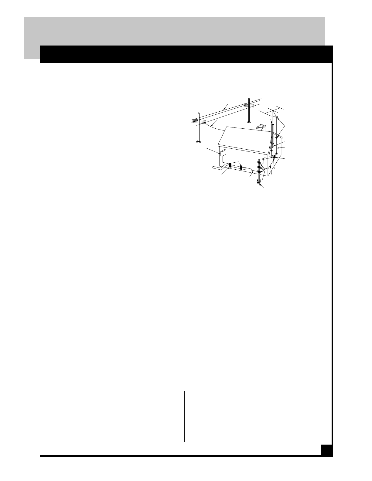
STANDOFF
INSULATORS
b
MAST
ANTENNA
LEAD-IN WIRE
c
GROUND WIRE
TO EXTERNAL ANTENNA
TERMINALS OF PRODUCT
ANTENNA
DISCHARGE UNIT
GROUND CLAMPS
OPTIONAL ANTENNA GROUNDING ELECTRODE
DRIVEN 8 FEET (2.44M) INTO THE EARTH
IF REQUIRED BY LOCAL CODES. SEE NEC
SECTION 810 - 21(f).
BONDING JUMPER
d
G
RO
UND C
LAM
PS
POWER SERVICE GROUNDING
ELECTRODE SYSTEM
(e.g. interior metal water pipe)
SERVICE
ENTRANCE
EQUIPMENT
SERVICE ENTRANCE
CONDUCTORS
GROUND CLAMP
POWER LINES
EXAMPLE OF ANTENNA GROUNDING ACCORDING TO
NATIONAL ELECTRICAL CODE INSTRUCTIONS CONTAINED
IN ARTICLE 810 - "RADIO AND TELEVISION
EQUIPMENT"
f. When the product exhibits a distinct change in performance this indicates a need for service.
19. Replacement Parts - When replacement parts are required,
be sure the service technician has used replacement parts specified
by the manufacturer or have the same characteristics as the
original parts. Unauthorized substitutes may result in fire, electric
shock or other hazards.
20. Safety Check - Upon completion of any service or repairs to
this product, ask the service technician to perform safety checks to
determine that the product is in proper operating conditions.
21. Outdoor Antenna Grounding - Before attempting to install
this product, be sure the antenna or cable system is grounded so as
to provide some protection against voltage surges and built-up
static charges.
a. Use No.10 AWG (5.3mm ) copper, No.8 AWG (8.4mm
(aluminum, No.7 AWG (10mm ) copper-clad steel or bronze wire
or larger, as ground wire.
b. Secure antenna lead-in and ground wires to house with standoff insulators spaced from 4 feet (1.22m) to 6 feet (1.83m) apart.
c. Mount antenna discharge unit as close as possible to where leadin enters house.
d. A driven rod may be used as the grounding electrode where
other types of electrode systems do not exist. Refer to the National
Electrical Code, ANSI/NFPA 70-1984 for information.
e. Use jumper wire not smaller than No.6 AWG (13.3mm ) copper
or equivalent, when a separate antenna grounding electrode is
used.
IMPORTANT INFORMATION CONT'D
S A F E G U A R D S
NOTE TO THE CATV SYSTEM INSTALLER:
THIS REMINDER IS PROVIDED TO CALL THE CATV SYSTEM INSTALLER’S ATTENTION TO ARTICLE 820 - 22 OF
THE NEC THAT PROVIDES GUIDELINES FOR PROPER
GROUNDING AND, IN PARTICULAR, SPECIFIES THAT THE
CABLE GROUND SHALL BE CONNECTED TO THE
GROUNDING SYSTEM OF THE BUILDING, AS CLOSE TO
THE POINT OF CABLE ENTRY AS PRACTICAL.
2
Page 4
PICO MACOM INC. 12500 Foothill Blvd. • Lakeview Terrace, CA 91342 • (818) 897-0028 • (800) 421-6511 • FAX (818) 834-7197
3
Section 4
D E S C R I P T I O N S
A N T E N N A S E L E C T I O N
Pre-Amp
MPA-25
Broadband Single Channel
VHF
MX-7
0R
LOW
VHF
DSV-3
DSV-4
HIGH
HLSJ
20 dBmv to
Headend
10 dBmv
UV SJ
UHF
MX-4U
19 dBmv
DC-20
Test
-1 dBmv
18 dBmv
11 dBmv
12 dBmv
DC-20
Test
UHF
DSU-3
UVSJ
20 dBmv to
Headend
19 dBmv
-1 dBmv
18 dBmv
17 dBmv
12 dBmv
9 dBmv
10 dBmv
12 dBmv
The proper reception of Local
Off-Air Television Signals
(UHF-VHF) is essential to a quality
Private Cable system. The use of a
commercial quality off-air antenna
is a must for optimum television
reception. Since every location has
different needs and problems, a site
survey should be completed before
starting the system. There are three
methods of off-air reception; Broadband, Single Channel Yagi or a combination of both. The method to use
will depend on the direction the
signals come from and the strength
of the signals. A good quality field
strength meter is a must for measuring signals.
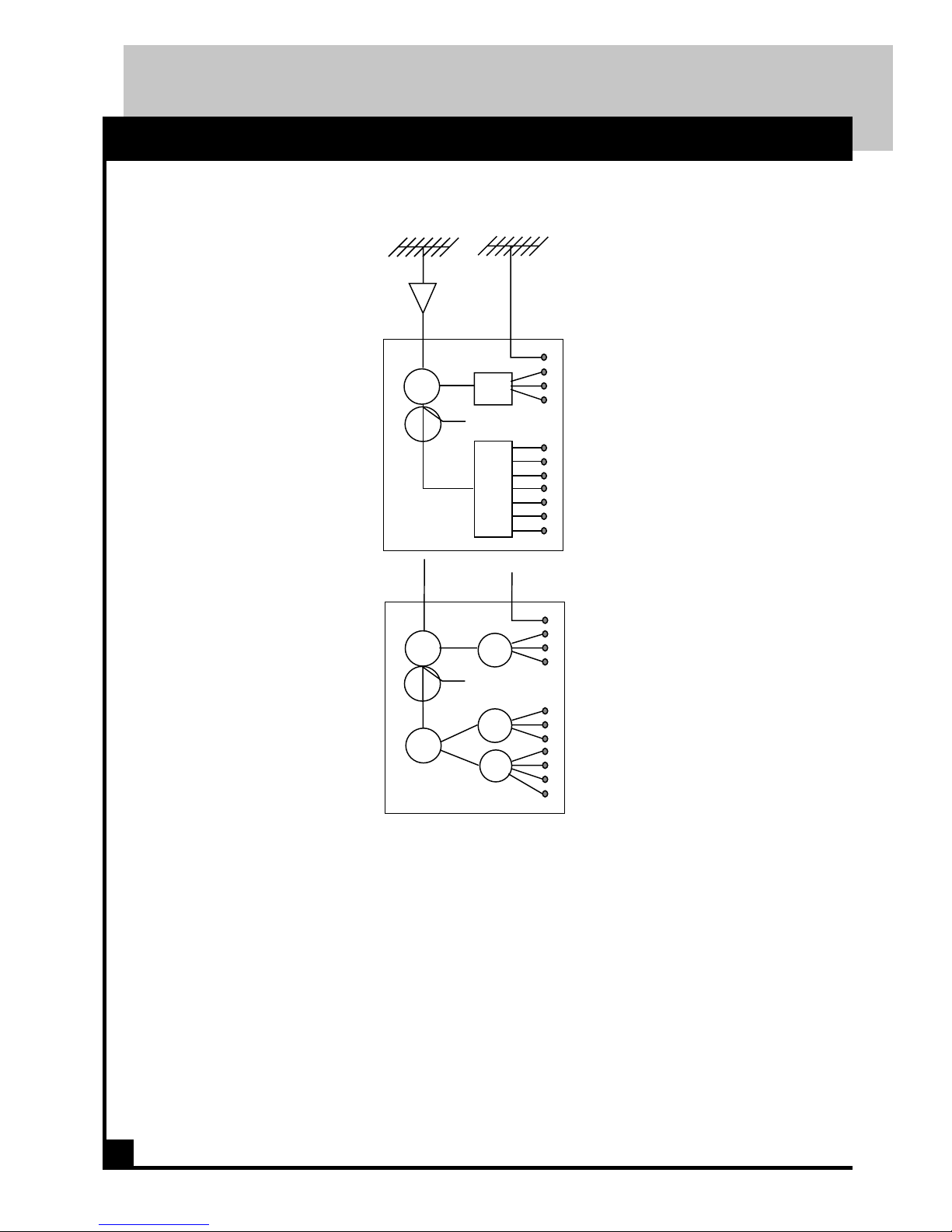
Broadband Antennas
These are used in areas with moderate
to strong signal levels and when the
signals are coming from the same
general direction. A mast mounted
broadband, low noise pre-amplifier
is recommended to boost the input
levels to over 20 dBmv. The incoming headend signal is divided into
the VHF and UHF bands using a
UVSJ separator. A DC-20 (directional coupler) is inserted for use as
a 20 dB down test point. The UHF
signals are then split with a DSU- *
series splitter and inserted into a
converter or channel processor. The
VHF signals are band separated once
again using a HLSJ hi/low separator. The low and high band signals
are then split using DSV-* high
isolation splitters. Each splitter out
is routed to the proper headend component.
* The number of ports is determined
by the number of channels.
Another option on VHF signals is to
use a MX-7 or MX-4V. The MX-7
& MX-4V are frequency selective
splitters for up to 7 non-adjacent
10 foot dish. In some areas where
the signals are very weak (outside
60 miles from the transmitter) a
single channel pre-amplifier must
also be used to bring the signal to
usable levels. Because these are
made to a specific channel they can
be entered directly into the headend
strip amplifier converter or processor input. High gain UHF antennas
are designed to cover blocks of channels such as 14-26, 26-38, 38-50,
50,62, 62-74 etc.
Combination Broadband & Single
Channel Yagis
Using a combination of antennas is
common in areas that have many
variable signal levels coming from
different directions. A good example is sites located between Los
Angeles, and San Diego. Los Angeles has 2,4,5,7,8,11,13,28 coming from the North, San Diego has
6,8,10,39 from the South.
The signals received off of broadband antenna will vary by as much
as 15 dB form channel to channel.
Signals received off an antenna are
never adjacent. A channel 2 would
not be located in the same geographic location as a channel 3
(channels 4 and 5, and channels 6
and 7 are adjacent in number only).
Part 73.606 of the “Code of Federal
Regulations” can be used to locate
the transmitter locations in the vicinity of your headend. The Society of Cable Engineers (SCTE) also
sells a paperback book of mapped
locations of each FCC licensed VHF
transmitter. The cost of the manual
is less than $25 and is well worth
the price.
VHF channels. Built in attenuators help adjust signal levels
evenly.
Single Channel Yagi*
These are used when the signals
are coming from opposite directions and at lower signal levels.
Single channel VHF Yagis are cut
to a specific channel enabling the
antenna to have much higher gain
than a broadband antenna.
*Note that the lower the VHF
frequency the larger the antenna.
It is analogous to satellite systems
using a 16 foot dish instead of an
Page 5

PICO MACOM INC. 12500 Foothill Blvd. • Lakeview Terrace, CA 91342 • (818) 897-0028 • (800) 421-6511 • FAX (818) 834-7197
D E S C R I P T I O N S
Strip amplifiers are devices used to boost the amplitude of individual TV signals derived from
an antenna or converter. The critical specifications used to judge their performance are:
1) Output Power
Measured in volts or dBmv
2) Gain
Measured in dB
3) Automatic Gain Control (AGC)
Measured in dB of dynamic range
4) Input Noise Figure
Measured in dB, the lower the better
5) Gain Selectivity
Similar to filter response
6) Aural Reduction Control
Control of the audio carrier amplitude
1) The Output Power is the maximum output of
an amplifier before signal distortion. At
maximum power, any further increase in gain
will distort the TV signal. Industry standard
output levels are 2 volt = 66 dBmv and 4 volt =
72 dBmv. One may notice that the output levels
are much higher than the maximum output levels
of modulators and channel processors. This is a
carry over from the early days of MATV where
the amplifiers were "looped" together for a
maximum combined output. Looping is only
acceptable when there are no adjacent modulated
channels.
2) Gain is a measure of the amount of amplification
available in the strip amplifier. Sufficient gain
should be developed in the amplifier to boost a
low level input to the maximum output power of
the amplifier.
66 dBmv units require 12 dBmv
12 dBmv + 54 dB gain = 66 dBmv output
72 dBmv units require 10 dBmv
10 dBmv + 62 dB gain = 72 dBmv output
3) Automatic Gain Control is the ability of a strip
amplifier to set the output power independent of
the input level. I like to think of AGC as "gain
in reserve". The simplest way to explain AGC
is with an example.
Assume a strip amplifier has a maximum gain of
54 dB and the output is set to 55 dBmv. The
input to the amplifier is initially 10 dBmv. Only
45 dB (55dBmv - 10dBmv) of the available 54
dB of gain is being used. Nine dB of gain is
presently in reserve. If the input drops to 0
dBmv the output will only drop to 54 dBmv but
all of the gain margin is used.
4) Input Noise Figure is a specification similar to
LNB temperature. The lower the number the
better the amplifier can produce clean pictures at
low input levels. The Input verses Noise Figure
table lists several input levels and the required
input noise figure required such that the amplifier will not contribute any noise to a 50 dB S/N
input signal.
Given Required
Input Level Noise Fig
-6 dBmv........................... 3 dB
-3 dBmv........................... 6 dB
0 dBmv ...........................9 dB
5) Gain Selectivity is a measure of the amplifiers ability to only amplify the desired channel.
Pico Macom strip amplifiers have sufficient filtering to operate adjacent to modulators or other
strip amplifiers. Bandpass filters are required
only under strong channel “skip” conditions or
when alternate channels are significantly stronger than the channel to be amplified. The purpose of the filter is to clear the adjacent channel
so that a modulated signal or a converted signal
may be inserted.
6) Aural Carrier Reduction Reducing the amplitude of the audio carrier allows the distribution system to operate at a higher level. More of
the amplifiers energy can be used to increase the
video carrier level. Since NTSC audio is frequency modulated, the audio quality is maintained for audio carrier levels as low as -17 dB
below the video carrier. Standard off-air broadcasters set the transmitted audio carrier only 5
dB below the video carrier.
4
S P E C I F I C A T I O N D E F I N I T I O N S
Page 6

PICO MACOM INC. 12500 Foothill Blvd. • Lakeview Terrace, CA 91342 • (818) 897-0028 • (800) 421-6511 • FAX (818) 834-7197
D E S C R I P T I O N S
F E A T U R E S & S P E C I F I C A T I O N S
Features
• Adjacent output channel compatible
• Wide dynamic range
• AGC controlled
• Adjustable sound trap
• Input and output test points
• AC convenience outlet
• Two year warranty
5
Specifications
Bandwidth (± .5 dB flatness)
LBS/MBS/HBS/UBS: ............................... 6 MHz
72L/72M/72M/72S: ................................... 6 MHz
FMS: .......................................... (88-108) MHz or
..................................... (92-108) MHz switchable
Gain
LBS/FMS/MBS/HBS/UBS: .... 54 dB below AGC
72L/72M/72H/72S:.................. 62 dB below AGC
Maximum Output Level
LBS/FMS/MBS/HBS/UBS: ................... 66 dBmv
72L/72M/72M/72S: ................................72 dBmv
@ (.5 dB sync compression):
Skirt Selectivity
LBS/MBS/HBS/72L/72M/72H
F center ± 6 MHz: .................................. -40 dB
F center ± 9 MHz: .................................. -50 dB
72S
F center ± 6 MHz: .................................. -30 dB
F center ± 9 MHz: .................................. -45 dB
UBS:
±3 Channels: ..........................................-50 dB
±6 Channels: ..........................................-65 dB
FMS: ....................................... Switchable
Wide - Channel 5: ............................. -40 dB
Narrow - Channel 6: .............................-20 dB
Noise Figure
LBS/MBS/HBS/72L/72M/72M: ................... 6 dB
72S: ................................................................ 7 dB
UBS: .............................................................. 9 dB
Controls
AGC Stiffness:....... ±1 dB for 30 dB input change
AGC Range: .................................... +4 to +40 dB
Sound Trap: ....................... 0 to -10 dB adjustable
Front Panel AGC Adjust Range .................. 15 dB
Test Points
Input:........................................................... -20 dB
Output: ........................................................-30 dB
General
Input Return Loss: ....................................... 10 dB
Output Return Loss: .................................... 15 dB
Power Requirements:................. 108 to 120 VAC,
60 Hz, 10 W
Mounting: ............................19” single rack space
Line Cord:.................................. 3 wire grounded,
3 wire convenience outlet
Operating Temperature...... -10 Deg to +50 Deg C
Finish: ..........................................................Plated
Dimensions: .............. 19” L x 2.875” D x 1.75” H
Weight: .................................................... 3.75 lbs.
• 1.75" low profile rack mounting
• New rugged individual packaging
• Available in Low, Mid, FM, High
Super band & UHF
• Lightning & line voltage surge protection
• Adjustable for worldwide channel band
widths and frequencies
Page 7

PICO MACOM INC. 12500 Foothill Blvd. • Lakeview Terrace, CA 91342 • (818) 897-0028 • (800) 421-6511 • FAX (818) 834-7197
P A N E L S
1. Model Number:
Each model of the single channel amplifier
uses a common chassis. The frequency
band and the output power is identified in
the product model number.
2. Power On LED:
Indicates power is on when lit.
3. Output Test Monitor:
A -30 dB output test port is provided for
ease of system alignment.
4. RF Gain, AGC:
The RF output level and the AGC threshold
are controlled from this potentiometer. A
description of the AGC function of the
amplifier is provided on page 4.
5. Aural Level:
This tunable notch filter allows adjustment
in the level of the audio carrier.
6. Input Test Monitor:
A -20 dB input test point is provided to
easily monitor the signal level originating
from the antenna.
7. IN:
The signal originating from a broadband or
yagi antenna is connected at this F connector.
Refer to page 3 for information on antenna
selection and proper input levels.
8. OUT:
The filter amplified signal is directly
available at this F connector.
9. Thru:
The outputs of other non-adjacent strip
amplifiers may be coupled through this F
connector.
10.Convenience Outlet:
This outlet is provided to allow the chaining
of amplifiers in the head-end equipment
rack. The polarized AC outlet is capable of
delivering up to 250 watts of AC power.
11. Power Cord:
This three prong polarized power cord is
approved by both UL and CSA for safe
operation of the amplifier. Do not cut the
ground terminal for both safety and
operational reasons. Connect to 108 to 125
VAC, 50/60 Hz electrical outlet.
6
F R O N T & R E A R P A N E L S
TEST OUTPUT
-30dB
AURAL
AURAL
LEVEL
CH-
3
4
5
TEST INPUT
-20dB
6
SINGLE CHANNEL AMPLIFIER
LBS
120VA
60HZ 10W
600VA MAX
+
+
+
+
+
+
+
THRU
IN
9
7
10
OUT
8
R.F. GAIN
AGC
2
1
Page 8

PICO MACOM INC. 12500 Foothill Blvd. • Lakeview Terrace, CA 91342 • (818) 897-0028 • (800) 421-6511 • FAX (818) 834-7197
I N S T A L L A T I O N
S I G N A L C O M B I N I N G M E T H O D S
7
The output levels of the off-air strip amplifiers
should be the same as the output of the modulators . The M600 modulators are usually combined with either the SP600, LBS/HBS or 72
series strip amplifiers. Three methods are sug-
V
H
+10dBmv
+14dBmv
+10dBmv
LBS/72L
LBS/72L
LBS/72L
+52dBmv
CH 2
CH 3
CH 4
CH 2
CH 3
CH 4
PHC-12
CHC-16
+10dB
to
+15dB
V
H
+10dBmv
+14dBmv
+10dBmv
+10dBmv
+14dBmv
+10dBmv
PAD
+47dBmv
+47dBmv
+47dBmv
+36dBmv
CA-30RK
+58dBmv
+58dBmv
CH 2
CH 4
EVEN
ODD
CH 3
V
H
M600
SP600
M600
SP600
M600
SP600
-16dB
+52dBmv
+52dBmv
+52dBmv
+36dBmv
CA-30RK
+58dBmv
+43dBmv
+43dBmv
+50dBmv
+50dBmv
+50dBmv
gested to combine strip amplifier,
modulator and processor outputs.
The PHC-12 consists of two rows of direc-
tional couplers combined by a hybrid splitter.
The directional coupler combining provides
high isolation (40 dB) between the inputs. Normally the odd channels are combined on one
row while even channels are combined on the
other row of directional couplers. The combiner loss is 16 dB per channel.
The CHC-16 provides both signal combin-
ing and post amplification of the headend signals. The unit is basically a passive combiner
and a CA30 all in one package. Up to 16 signals
may be combined using the CHC-16. The
combiner gain is 15 dB per channel.
The final method of combining signals uses
three hybrid splitters per headend rack. The odd
channels are combined in one splitter, the evenchannels in another splitter and the two splitters are combined to a single
output with a third splitter. Each rack is then combined with a final splitter
prior to the CA-30 post amplifier.
Page 9

PICO MACOM INC. 12500 Foothill Blvd. • Lakeview Terrace, CA 91342 • (818) 897-0028 • (800) 421-6511 • FAX (818) 834-7197
A L I G N M E N T
I N P U T F I L T E R, O U T P U T F I L T E R, A U R A L L E V E L
8
amplifiers limit the range that each amplifier can be
tuned. The tuning bands for each of the products is
listed.
UBS Any UHF channel to
any UHF channel
LBS & 72L
Band 1 Channels 2,3,4
Band 2 Channels 5 &6
MBS & 72M
Band 1 Channels A, B, C, D
Band 2 Channels E, F, G, H, I
HBS & 72H Any highband channel to
any highband channel
The Pico Macom single channel amplifiers can be
aligned to other channels within the frequency band.
The input and output filter components within the
Test Equipment
Sweep Generator System Wavetek 1076,1081,1901
External Marker Generator Agile Modulator
TV Signal Generator Sencore VA-62
Spectrum Analyzer HP 8558B/182T
IN
TOP VIEW
XFMR
BOARD
POWER
SUPPLY
RF GAIN
AGC
AURAL
LEVEL
INPUT
TEST
-20dB
OUTPUT
TEST
-30dB
THRU OUT
INPUT
DETECTOR
RF
THRU
OUT
INPUT
BOTTOM VIEW
C1
C2
C3
C4
C5
C6
C7
C8
C9
C10
C11
Agile Modulator
RF
INPUT
V
H
OUTPUT
SWEEP
GENERATOR
HV
External
Markers
SWITCH FOR WIDE & NARROW
(CHANNEL 5 &6) FM BAND.
FMS ONLY.
Page 10

PICO MACOM INC. 12500 Foothill Blvd. • Lakeview Terrace, CA 91342 • (818) 897-0028 • (800) 421-6511 • FAX (818) 834-7197
9
BENCH ALIGNMENT
1. Do Not remove the cover. Plug in the unit to
108 to 125 Vac outlet.
2. Set the sweep generator center frequency to
the center frequency of the desired channel.
3. Connect the TV signal generator or the agile
modulator to the sweep generator external
marker input.
4. Set the sweeper output level below the AGC
input range -10 dBmv for the 72* and 0 dBmv
for the *BS
5. Adjust C11 to move the audio notch to the
upper channel edge.
6. Coarse tune the amplifier and output filters by
adjusting C1, C3, C6, C8 and C10.
7. Fine tune the filters by adjusting C1, C2 ,C3
and C6, C7, C8, C9 and C10 to obtain a
response similar to the figure below.
8. Connect the sweep generator to the "Thru"
and "Out" connectors. Adjust the bandstop
thru filter C4 and C5 for a response similar to
the figure to the right.
9. Connect a TV signal generator to the input and
a spectrum analyzer to the strip amplifier output.
10. Adjust the front panel Aural Level to locate the
notch at the lowest frequency it will tune. Then
adjust C11 until the notch is exactly on the
audio carrier.
11. Set the front panel RF gain AGC control to
minimum gain ( maximum AGC).
12. Vary the input level from +4 dBmv to 30 dBmv
and verify the output level remains constant at
a level of:
LBS 54 dBmv ± 2 dB
72L 62 dBmv ± 2 dB
13. Set the RF gain AGC control to maximum gain
(minimum AGC).
14. Vary the input level from +12 dBmv to 40
dBmv and verify the output level remains
constant at a level of:
LBS 54 dBmv ± 2 dB
72L 62 dBmv ± 2 dB
I N P U T F I L T E R, O U T P U T F I L T E R, A U R A L L E V E L
6 MHz
6 MHz
F center
6 MHz
2 MHz/Div
10 dB log/ Div
F video F audio
F center
6 MHz
2 MHz/Div
10 dB log/ Div
F video F audio
Page 11

PICO MACOM INC. 12500 Foothill Blvd. • Lakeview Terrace, CA 91342 • (818) 897-0028 • (800) 421-6511 • FAX (818) 834-7197
W A R R A N T Y
FIVE YEAR LIMITED WARRANTY
P
ico Macom, Inc.
warrants to the
original purchaser
this product shall be
free of defects in
material and
craftsmanship with only the
limitations or exclusions set out
below.
During the warranty period Pico
Macom Inc. or an authorized Pico
Macom service facility will provide
free of charge, the parts and labor
necessary to correct defects in
material and workmanship.
WARRANTY DURATION
This warranty shall terminate five
years from the original date of
purchase of the product or at a time
the product is
1. Misused or damaged due to
neglect or improper installation
2. Modified
3. Repaired by someone other than
the warrantor
4. Sold by the original purchaser
STATEMENT OF
REMEDY
To obtain warranty service,
contact the salesperson where the
product was obtained. You will be
issued a Return Authorization (RA)
number which will be used to track
your product.
Be prepared to provide;
1. The model number and channel
number of the product
2. The date of purchase
3. A specific identification of the
problem
Deliver the products to Pico Macom
Inc. or ship the products in the original
packing material at the address at the
bottom of the page. Include
satisfactory evidence of the date of
purchase.
Products will not be accepted by
Pico Macom Inc. without the RA
number clearly indicated on the
shipping label.
The foregoing constitutes the Pico
Macom, Inc. entire obligation with
respect to this product and the original
purchaser and any user or owner shall
have no other remedy and no claim for
incidental or consequential damages.
Some states do not allow limitations
on how long an implied warranty lasts
or do not allow the exclusions or
limitation of incidental or
consequential damages, so the above
limitation and exclusion may or may
not apply to you.
This warranty gives you specific
legal rights, and you also have rights
which vary from state to state.
10
 Loading...