


G2301-m Flight-Ready Analyzer
for CO2/CH4/H2O
User’s Guide

TABLE OF CONTENTS |
|
Conventions |
5 |
Safety |
6 |
Getting Started |
8 |
Installation |
10 |
Basic Analyzer Setup.................................................................................. |
11 |
Basic Operation |
13 |
Shutdown Procedure .................................................................................. |
15 |
In Case of Electrical Power Outage ............................................................ |
17 |
Appendix A - Status Log Messages |
18 |
Normal Start Up Messages ......................................................................... |
18 |
Appendix B - List of GUI Functions |
19 |
Additional Tools and Information................................................................. |
19 |
Settings, Tools and Help Menus: ................................................................ |
19 |
Alarm Panel ................................................................................................ |
21 |
Digital Readouts.......................................................................................... |
21 |
Start / Stop Data Log Button ....................................................................... |
22 |
Data Log Filename and Path ...................................................................... |
22 |
Data Window............................................................................................... |
22 |
Instrument Status........................................................................................ |
22 |
Data Source and Data Key Pull Down Menus............................................. |
22 |
Precision Pulldown Menu............................................................................ |
23 |
Status Log Window ..................................................................................... |
23 |
Reset Data Buffer Button ............................................................................ |
23 |
Data Buffer Level Meter .............................................................................. |
23 |
Graph Zooming ........................................................................................... |
23 |
File Management ........................................................................................ |
24 |
Setup Tool................................................................................................... |
26 |
Picarro G2301-m Analyzer User’s Guide |
|
Rev. C 2/11/11 |
2 |

Appendix C – EXTERNAL VALVE SEQUENCER |
27 |
Appendix D – REMOTE DATA ACCESS |
32 |
Appendix E – CALIBRATION |
35 |
Appendix F – SERVICE AND MAINTENANCE |
37 |
Appendix G – TROUBLESHOOTING |
42 |
Appendix I – TRANSPORTATION AND STORAGE |
45 |
Appendix J – LIMITED WARRANTY |
46 |
Picarro G2301-m Analyzer User’s Guide |
|
Rev. C 2/11/11 |
3 |

INTRODUCTION
Thank you for purchasing a Picarro product. Your Picarro Analyzer has been designed and manufactured to provide the highest quality data, easily and reliably.
This manual is an important part of your purchase as it will help familiarize you with the system and explain the numerous features. Please read this manual thoroughly before starting the installation and using your instrument.
Please don’t hesitate to contact Picarro or your authorized Picarro distributor should you have additional technical or applications questions. We provide webbased as well as direct e-mail and telephone support.
Contact Information
Website access to user forums: |
www.picarro.com |
Email: |
techsupport@picarro.com |
Telephone: |
1 (408) 962 3950 direct or 1 (408) 962 3900, |
|
extension 3950 |
Picarro, Inc. reserves the right to change or update the contents of this manual and to change the specifications of its products at any time without prior notification. Every effort has been made to keep the information in this document current and accurate as of the date of publication or revision. However, no guarantee is given or implied that this document is error free or that it is accurate with regard to any specification. Please comment on any aspects of this manual to techsupport@picarro.com. Your input is very helpful.
Picarro and the Picarro Logo are trademarks of Picarro, Inc.
2010 Picarro, Inc. All rights reserved. 480 Oakmead Parkway
Sunnyvale, California CA 94085
USA.
Phone: 408.962.3900 (main) Fax: 408.962.3200
Website: www.picarro.com
Picarro G2301-m Analyzer User’s Guide |
|
Rev. C 2/11/11 |
4 |

CONVENTIONS
Throughout the manual you will see graphic icons representing important information in the text. The purpose of these icons is to provide a visual convention to alert you of a stop in the flow of the manual, where an important note or safety hazard alert is posted.
NOTE is an important procedure of which you should be aware of before proceeding.
CAUTION alerts you of a potential danger to equipment or to the user.
WARNING indicates an imminent danger to the user.
REMINDER is a helpful hint to procedures listed in the text.
Picarro G2301-m Analyzer User’s Guide |
|
Rev. C 2/11/11 |
5 |

SAFETY
The Picarro Analyzer complies with the following safety standards:
CE: |
IEC EN61010-1:2001 (safety) and EN61326-1:2006 (EMC) |
|
requirements for electrical equipment for measurement, |
|
control and laboratory use. |
FDA/CDRH 21 |
CFR Parts 1040.10-11 |
LASER SAFETY: The Picarro Analyzer is classified as a Class 1
Embedded Laser Product
WARNING: CLASS 3B INVISIBLE LASER RADIATION WHEN
OPEN. AVOID EXPOSURE TO THE BEAM.
There are lasers used inside the analyzer, emitting a maximum of 50 mW of CW light in the near-infrared. There are no user serviceable components within the analyzer enclosures and so you should not open any of these enclosures within the analyzer. FAILURE TO FOLLOW THIS INSTRUCTION COULD RESULT IN
EXPOSURE TO CLASS IIIB LASER RADIATION, which can permanently damage eyes and skin.
Safety Labels: |
The following label is affixed to the main lid of the cavity |
|
enclosure. |
CAUTION
1” |
CLASS 3B INVISIBLE LASER |
|
|
|
RADIATION WHEN OPEN |
|
AVOID EXPOSURE TO THE BEAM |
|
2.125” |
|
|
|
|
WARNING: DO NOT OPERATE IN AN EXPLOSIVE ATMOSPHERE! DO NOT OPERATE IN THE PRESENCE OF FLAMMABLE GASSES OR FUMES.
WARNING: DO NOT OPERATE IN A WET ENVIRONMENT.
Picarro G2301-m Analyzer User’s Guide |
|
Rev. C 2/11/11 |
6 |

CAUTION: The inlet gas connector on the back panel, and its immediate vicinity, runs hot during operation of the analyzer. Take care when connecting gas lines or working at the rear of the instrument to wear protective gloves or avoid contact with these surfaces.
CAUTION: The analyzer contains HOT SURFACES and utilizes
HIGH VOLTAGES inside the instrument. There are no user serviceable components except the filter within the analyzer and so you should not open the analyzer except to replace the filter. Do not open any enclosures within the analyzer.
CAUTION: Some of the analyzer components are heavy. To avoid injury, please use proper lifting procedure when moving or installing the equipment.
NOTE: Although the analyzer components can be optionally configured for rack mounting, they require supports in the rack, such as a shelf or side L-brackets, and cannot be safely supported by the front panel bolts alone.
NOTE: The Picarro Analyzer contains no user serviceable components except the particulate filter in the analyzer and the external vacuum pump. Do not attempt repairs; instead, report all problems to Picarro.
Please contact Picarro if you have any questions regarding the safe operation of this equipment. Refer to the appropriate section within this document relating to pump and filter replacement procedures.
Picarro G2301-m Analyzer User’s Guide |
|
Rev. C 2/11/11 |
7 |

GETTING STARTED
All Picarro products are inspected and tested prior to shipment from the factory.
In addition, the instruments are packed in an inner box which is encased in a larger outer box. The inner box is equipped with a shock indicator. The shipping container system has been specially tested and proven to be safe for most dropping, crushing or spiking events.
ACCEPTABLE Outer Box Condition /Inner Box Shock Indicator Condition
DAMAGED Outer Box Condition /Inner Box Shock Indicator Condition
In the event of severe damage to the outer box or activation (red color in center) of the shock indicator:
Photograph the damages and contact Picarro (please email pictures if possible) for consultation on best course of action.
Picarro G2301-m Analyzer User’s Guide |
|
Rev. C 2/11/11 |
8 |

CAREFULLY unpack the contents from the boxes.
The shipment should contain the following (depending upon configuration, consult packing list for full details):
Box 1 |
|
1 Analyzer Module |
includes all of the data acquisition, control, |
|
and communications hardware and firmware |
|
to perform all gas handling, spectral |
|
collection and analysis. |
2 A/C Power Cables |
(North America only), one for the analyzer, |
|
one for the pump. |
|
For customers out side of the North America, |
|
power cables will be required. The power |
|
inlets are a C14 male connector which |
|
requires a C13 female connector (same style |
|
as found in most desktop computers). The |
|
equipment automatically switches to the local |
|
line voltage, so the other end can be plugged |
|
directly into a standard outlet. |
1 Accessory Bag: |
assorted accessories: |
1 USB flash drive |
pre-loaded with back-up software |
1 Certificate of compliance |
|
1 Hardcopy User Manual |
|
Box 2 |
|
1 Pump Module |
provides vacuum required for sample gas |
|
sequencing into and out of the Analyzer. |
If any of these items are missing, contact Picarro for a replacement. Inspect each item to assure it is not damaged.
It is recommended that you keep the shipping packages. These shipping packages are also a very good way to ship the system to other labs or field stations, unless they will get wet. Please contact Picarro for options on transporting systems to remote labs.
Picarro G2301-m Analyzer User’s Guide |
|
Rev. C 2/11/11 |
9 |

INSTALLATION
This section describes the setup and installation of the Picarro Analyzer. Please read and understand this section thoroughly before proceeding with the installation.
WARNING: Do not attach electrical power to, or start the analyzer until after attaching and turning on the External Vacuum Pump. Do not disconnect the vacuum line while the analyzer is running.
Failure to do so could result in damage to the optics.
WARNING: Picarro sells USB enabled devices, such as GPS, which are approved for use. Please do not connect USB hubs or unapproved USB devices, other than flash drives to the computer because they can interfere with the operation of the analyzer.
WARNING: If rack mounted, the Analyzer cannot support itself using a front rack mount kit alone. The instrument must be supported by a shelf or additional rails attached to the rack.
CAUTION: It is imperative that the analyzer have adequate ventilation and/or cooling to maintain the ambient temperature below 35 °C when operating. Failure to provide adequate a irflow, especially clearance at the front and rear panels, to ensure proper airflow and/or cooling to the analyzer will result in overheating of the analyzer causing a shutdown and potential damage. There should be 4” (10cm) of clearance in the front and back of the analyzer.
Thermal |
Min |
Max |
Description |
Specifications |
|
|
|
|
|
|
|
Ambient Operating |
10 °C |
35 °C |
Worst-case environmental limits |
Temperature |
|
|
(unless otherwise specified) |
|
|
|
|
CAUTION: If the analyzer has been stored at less than 10 ° C, allow the components to equalize to room temperature before starting the installation process.
NOTE: Take care to ensure that warm air is exhausted from any enclosure in which the analyzer is mounted.
Picarro G2301-m Analyzer User’s Guide |
|
Rev. C 2/11/11 |
10 |
Basic Analyzer Setup
1Remove the Analyzer and the External Vacuum Pump from their respective shipping containers.
2Place the Analyzer on a bench top or flat surface. Place the External
Vacuum Pump near-by or on the floor. Don’t push the analyzer into position yet, there are cables to be installed at the back.
3Unpack the analyzer accessories. (gas line, AC power cables, manual, certificate of compliance, and USB Flash Drive). The Certificate and USB drive should be stored in a safe place. They may be required if you contact us with questions about your analyzer.
4Remove the caps from the Analyzer gas connection inlet and vacuum connection ports. Save the caps for later use, they should be reinstalled if the analyzer is stored, moved or shipped.
5Remove the caps from External Vacuum pump. Save the caps for later use.
They should be reinstalled if the pump is stored, moved or shipped.
6Attach the gas line between the Analyzer vacuum port and the External
Vacuum Pump. See Figure 1. Hand tighten the nut, then make an additional 1/4th turn with an 11/16” wrench (not supplied).
7Connect the AC power cable to the External Vacuum Pump but do not plug it in.
8If desired, attach a tube to the External Vacuum Pump exhaust port and direct to a safe place for venting the mixture of sample gases.
Picarro G2301-m Analyzer User’s Guide |
|
Rev. C 2/11/11 |
11 |
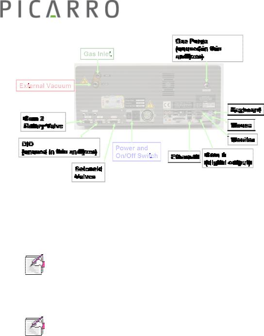
Figure 1 - Back of Analyzer showing gas supply, electrical and computer connections.
9Attach a PS2 mouse, PS2 keyboard, Ethernet cable (not supplied), and VGA monitor display cable to the computer connections on the back of the Analyzer.
NOTE: The software to operate the instrument will start automatically after the operating system has loaded.
The user interface will appear a few seconds after the instrument software starts (see the figure on the following page).
NOTE: As the instrument is starting up, it is normal for there to be a delay in reporting data. This can take several minutes depending on how long it takes for the internal temperature to reach its operating point, and it is normal during this time for some concentration readings to be negative or constant. Additionally, the data selection pull down menus will not be populated with the appropriate items until data is actually being reported in the graph. This is typically less than 30 minutes, but depending on ambient temperature, the analyzer can take up to 1 hour to stabilize.
Picarro G2301-m Analyzer User’s Guide |
|
Rev. C 2/11/11 |
12 |
BASIC OPERATION
When the main power is turned on the analyzer will automatically start, including the Graphical User Interface (GUI). The screen will look like that in Figure 2.
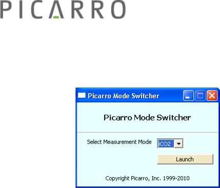
Figure 1 – Mode Switcher.
Icons on the desktop are as follows:
∙ControllerInstrument diagnostics and service information
∙Picarro Mode SwitcherRestarts analyzer in different measurement mode. Most analyzer models are configured for one mode and may not include the Mode Switcher. (Figure 1). If the analyzer has multiple modes, this allows the user to switch between them easily.
∙Start InstrumentRestarts the software if the software has been shut down (optional on some systems)
∙Stop PicarroShuts down software (but not computer).
∙Coordinator LauncherStarts the coordinator software which controls sample introduction to the analyzer. (Some analyzers may not have this due to their configuration).
The analyzer will not begin producing data until all the measurement parameters have reached their operational set points. A message will be display in the Status log window (see Figure 2, bottom panel) when each set point is reached. A full explanation of each status log message can be found in Appendix A.
Picarro G2301-m Analyzer User’s Guide |
|
Rev. C 2/11/11 |
13 |

Figure 2 - Layout of the Picarro analyzer GUI, G2000 series. A full explanation of the GUI functions can be found in Appendix B
Data will be saved automatically once the analyzer starts to produce data. The data in the GUI is the continuous real time read out from the analyzer. A user relevant subset of this data is stored in C:\Userdata\DataLog_User
\YYYY\MM\DD, where Y=year, M=month, D=day. Further details can be found under the file management section in Appendix B.
In order to measure discrete samples (such as individual gas bags) or from multiple locations (when switching valves draw in ambient air from different heights) a separate software window (coordinator) is used to control the sample source and match the corresponding real time read out with the sample source.
Depending on system configuration, coordinator programs may not be included.
Picarro G2301-m Analyzer User’s Guide |
|
Rev. C 2/11/11 |
14 |
sample A at t=0 sample B at t=1 sample C at t=2
hardware
software
data file
A B C
Sampling
Analyzer
GUI |
Coordinator |
data for |
|
|
A |
data for B
data for
all data C t=0 to t=3
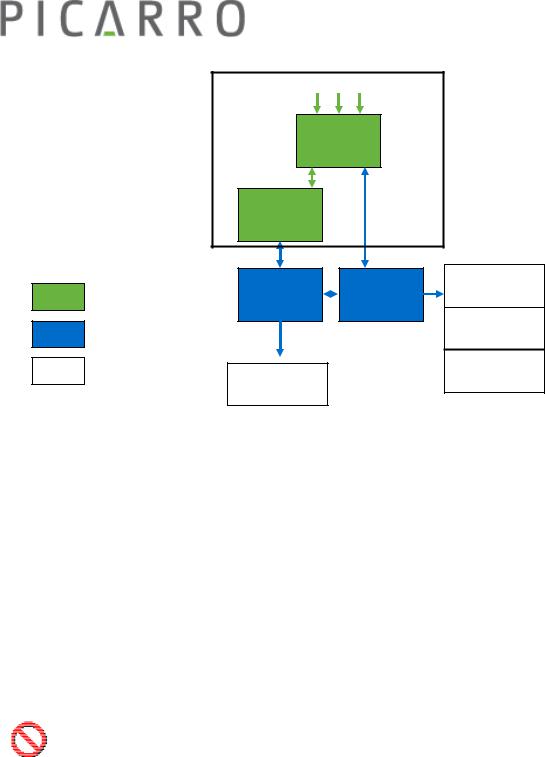
Figure 3 - Overview generalized schematic of Picarro analyzer system hardware, software, and data file generation.
The samples A, B, and C are introduced into the analyzer sequentially by a sampling module, if present. The sampling module could be a set of customersupplied valves, a valve manifold, a discrete sampling module, or other device. The timing of sample introduction is controlled by the coordinator or valve sequencer software. The analyzer measures continuously and reports the data to the GUI which saves a single file where all data is reported as a function of time. The coordinator gets data from the GUI and creates a single file, the data is reported as a function of sample.
Shutdown Procedure
CAUTION: A flow of clean, relatively dry gas should always be directed through the instrument for several minutes prior to shutdown. Trapping a high-moisture content gas sample in the cavity can cause condensation damage to the mirrors as the instrument cools from its operating temperature.
Picarro G2301-m Analyzer User’s Guide |
|
Rev. C 2/11/11 |
15 |
 Loading...