

Page 1
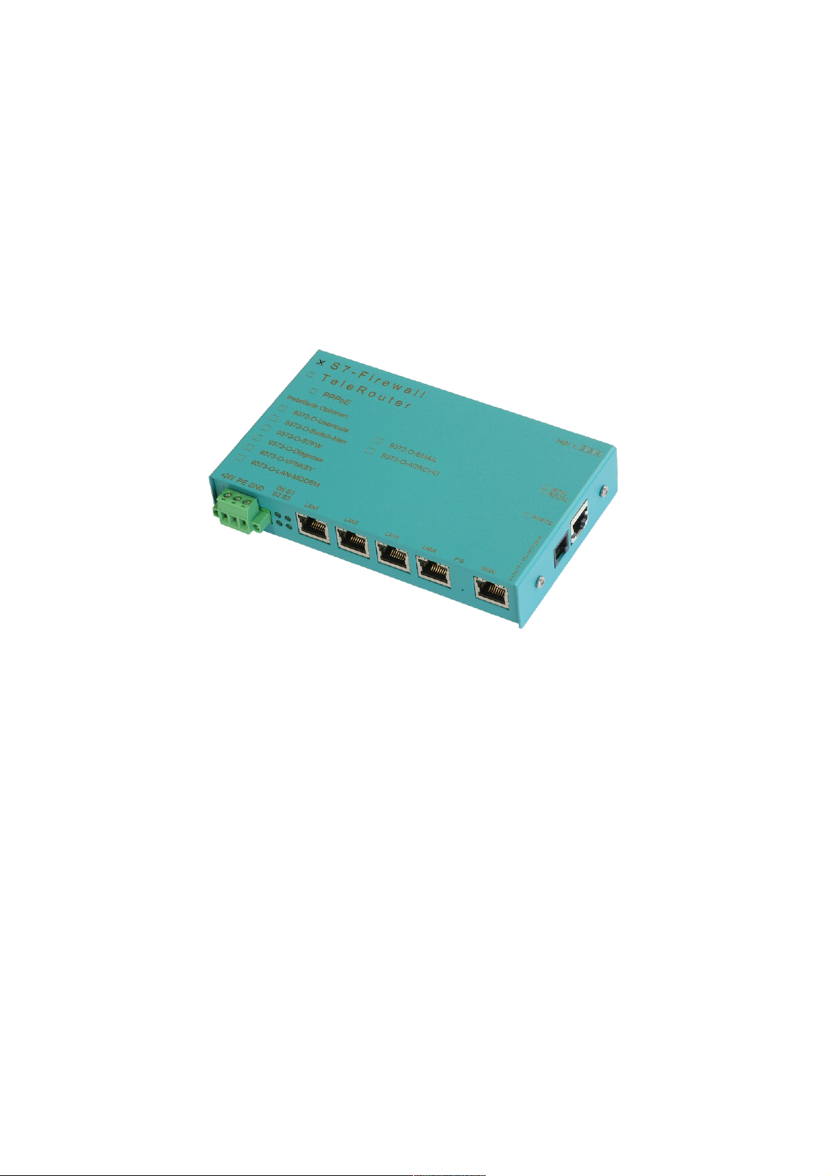
S7-Firewall
user manual
(english)
Art.Nr. 9373-S7-FIREWALL
17.05.2019
© PI 2019
Page 2

Content
1 Installation ........................................................................................................................................3
1.1 Power connection ......................................................................................................................3
1.2 LAN-connector .........................................................................................................................3
1.3 introduction ...............................................................................................................................3
1.4 hardware execution ...................................................................................................................3
1.4.1 standard hardware execution .............................................................................................3
1.5 configuration .............................................................................................................................4
1.6 configuration .............................................................................................................................4
1.7 network configuration ...............................................................................................................5
1.8 DHCP fixed MAC /IP address mapping ...................................................................................7
1.9 NTP client .................................................................................................................................7
1.10 web user ..................................................................................................................................7
1.11 S7 firewall settings ..................................................................................................................8
1.12 entering of the HMI / PG station ............................................................................................8
1.13 entering of the SPS station ......................................................................................................8
1.14 entering of the S7 firewall connections ..................................................................................9
1.15 The rulescript ..........................................................................................................................9
2 Technical data .................................................................................................................................10
2.1 pin assignment power supply ..................................................................................................10
2.2 Pinning Ethernet .....................................................................................................................10
Handbook S7-Firewall Page 2 of 12
Page 3
1 Installation
1.1 Power connection
For the power supply to the device is either the included AC adapter or an existing local power
supply with min. 24V DC 350mA power connected to the 3-pin green plug. In the included AC plug
adapter the power poles are marked with colored sleeves.
The PLUS-pole with the color "red", the MINUS pole with the color "blue". Connect the
POSITIVE pole of the left screw terminal and the NEGATIVE pole on the right (outer) screw
terminal. The middle connector is used to ground and must be connected to PE.
1.2 LAN-connector
This connector is an autosensing 10/100 Mbit/s connector. For the connection to a Hub or a network
connector, you should use a socalled patch-cable (both sided RJ-45, 1to1, shielded).
1.3 introduction
The S7 firewall is a scalable "SPS firewall", which not only filters IP / MAC addresses. For userdefined connections the access can be restricted to any data areas of the SPS or be set. The S7
firewall can be incorporated between any SPS and operating / programming level. The S7 firewall
automatically detects the installation direction. There are only configured connections permitted.
1.4 hardware execution
1.4.1 standard hardware execution
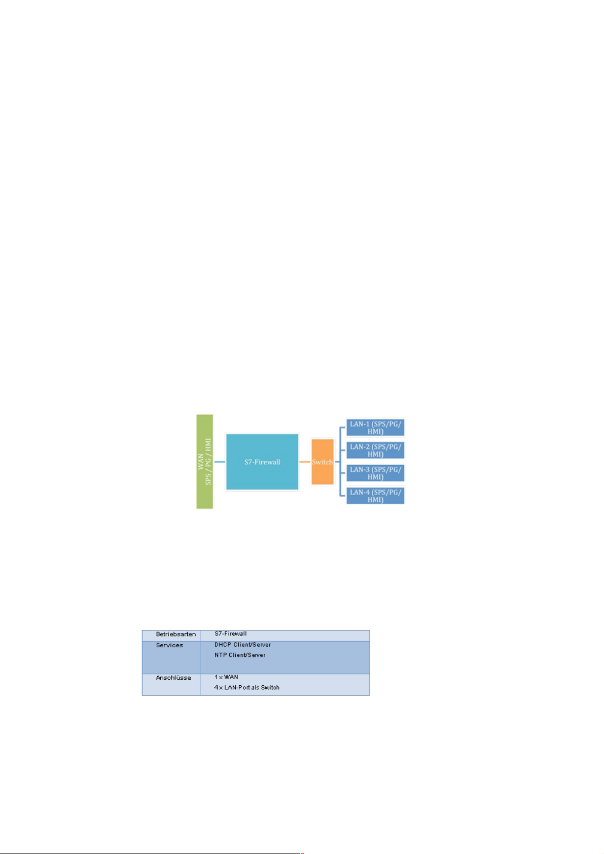
In the standard execution the S7 firewall is equipped with a WAN port and 4 LAN ports configured
as a switch.
Page 3 of 12 Handbook S7-Firewall
Page 4
1.5 configuration
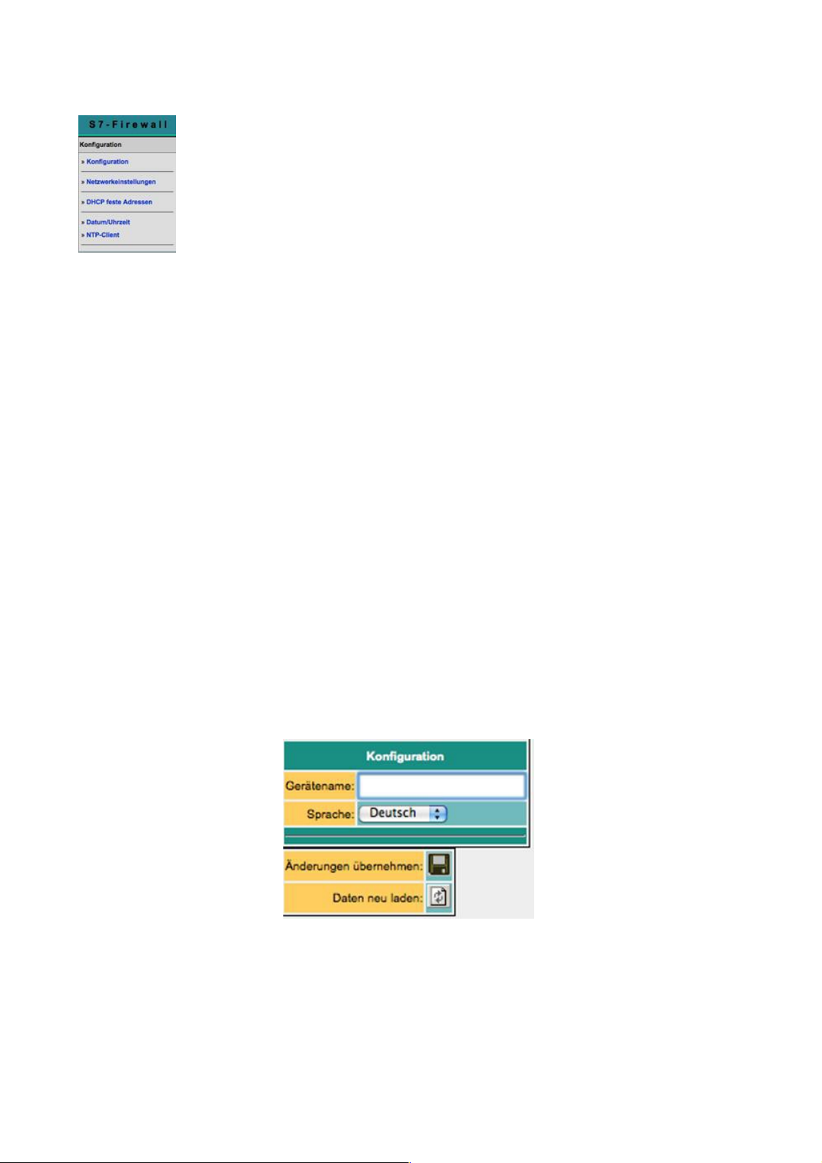
In the configutation the network settings etc. can be configured. The entry forms are
self-explanatory in general. But we will like to receive suggestions from users to
make operation even easier.
In delivery the following IP addresses are set:
192.168.1.57
192.168.2.1
You have the following options, to address the S7 firewall via web browser:
On the PC an IP address from the corresponding line segment awarded (eg 192.168.1.100 or
192.168.2.100) and connect the corresponding PC with LAN or WAN via Ethernet. Enter
http://192.168.1.57, bzw. http://192.168.2.1 in your web browser. Or set your computer to
automatically obtain IP address and connect him to the LAN port of the TeleRouter. TeleRouter
automatically tells the PC an IP address. In your browser, you can use the device with
http://telerouter
That the S7 always starts with these basic settings without the made settings get lost, proceed as
follows:
• place a paper clip or something similar ready to operate the factory reset button. Do not
worry, we make no factory reset. The button is hidden between WAN and LAN ports. There
is a small hole. There, insert the paper clip.
• unplug the device
• turn power back
• When the four LED's go out and only the Power LED is on, hold down the button with the
paper clip until all 4 LEDs flash quickly.
• release the button
• If the LED S3 (bottom right) lights press the button again.
Then the device will boot in the default settings. Now, the desired changes to the Network settings
can be made. These settings are only after restart the device active.
1.6 configuration
Handbook S7-Firewall Page 4 of 12
Page 5
parameters possible settings purpose
device name "as desired"
language
deutsch
english
specifies the language of the user level
Maybe after the change relod the page
in the web browser
standard gateway as specified
from WAN via DHCP
from WAN via PPPoE
from LAN via DHCP
from modem via PPP
1. DNS
2. DNS
routing mode office LAN -> routing interface
Maschine routing interface -> LAN
routing interface WAN/IP IP routing via WAN
modem IP routing via modem
WAN/PPPOE IP routing via PPPoE at the WAN-Port
WAN/OVPN routing via OVPN at the WAN-Port
WAN/Bridge ethernet routing at the WAN-Port
1.7 network configuration
Page 5 of 12 Handbook S7-Firewall
Page 6
parameters possible setting purpose
standard gateway as desired via DHCP
1. DNS
2. DNS
1-3. IP address with
netmask
IP address / netmask
If the netnask is 0.0.0.0 the
netmask will automatically calculated
depending to A, B, C-B network.
e. g.
192.168.0.x -> 255.255.255.0
10.x.x.x -> 255.0.0.0
When using fixed IP addresses
at least 1 IP address is to
configure. Otherwise the device starts
with the factory settings.
DHCP
no
kein DHCP verwenden
The remeaining DHCP parameters
will not be used
client
The network interface is
a client and obtains the IP
address automatically from a
DHCP server.
The remeaining DHCP parameters
will not be used
server
The Netzwerkinterface provides a
DHCP server. The remeaining DHCP
parameters will be used.
start IP start IP address
start IP address when operating as a
dhcp server
end IP end IP-Adresse
end IP address when operating as a
dhcp server
subnet subnet address
address of the subnet for the award
of IP addresses as a DHCP server
domain free
name of the domain by using
the DHCP server
router IP IP address
Is the IP address that the operation
as a DHCP server as a gateway is passed
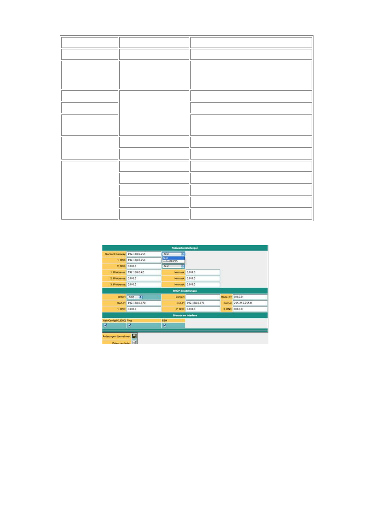
The WAN / LAN port has shared IP addresses. Up to 3 different IP addresses and subnets are
configured. The port can also be used as a DHCP server or client. The necessary data for the IP
assignment to be entered here. For the operation as a DHCP / server there can be set fixed
assignments MAC IP address (See below "DHCP fixed MAC /IP address mapping"). Further
defines what services are available at the port (Web config), ping, SSH (for developers only)
Handbook S7-Firewall Page 6 of 12
Page 7
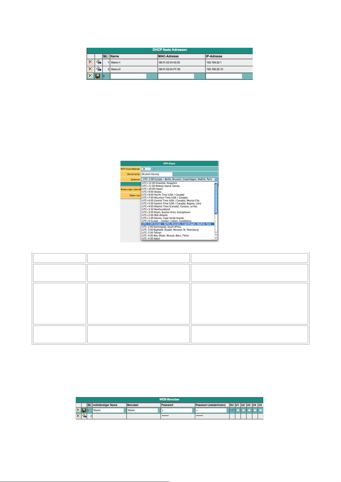
1.8 DHCP fixed MAC /IP address mapping
If the built-in DHCP server (at the WAN or LAN) is operated, it can be useful, to allocate specific
IP stations always the same IP address. Here you can specify which MAC address is replaced by
which IP address.
1.9 NTP client
So that TeleRouter always runs at the current time, we have implemented an NTP client. So
TeleRouter can automatically via internet or by any other available in the network time server
synchronize the date and time.
paramters possible settings purpose
NTP client
operation
yes
no
Turns the NTP client on or off.
service name
IP address /
domain name of the NTP
servers
Enter the IP address or the domain
name of the NTP server. Make sure that
theses
servers through the specified routing path
is accessible
time zone
time zone, in which the TeleRouter
is operated
necessary, for the correct local time at the
TeleRouter
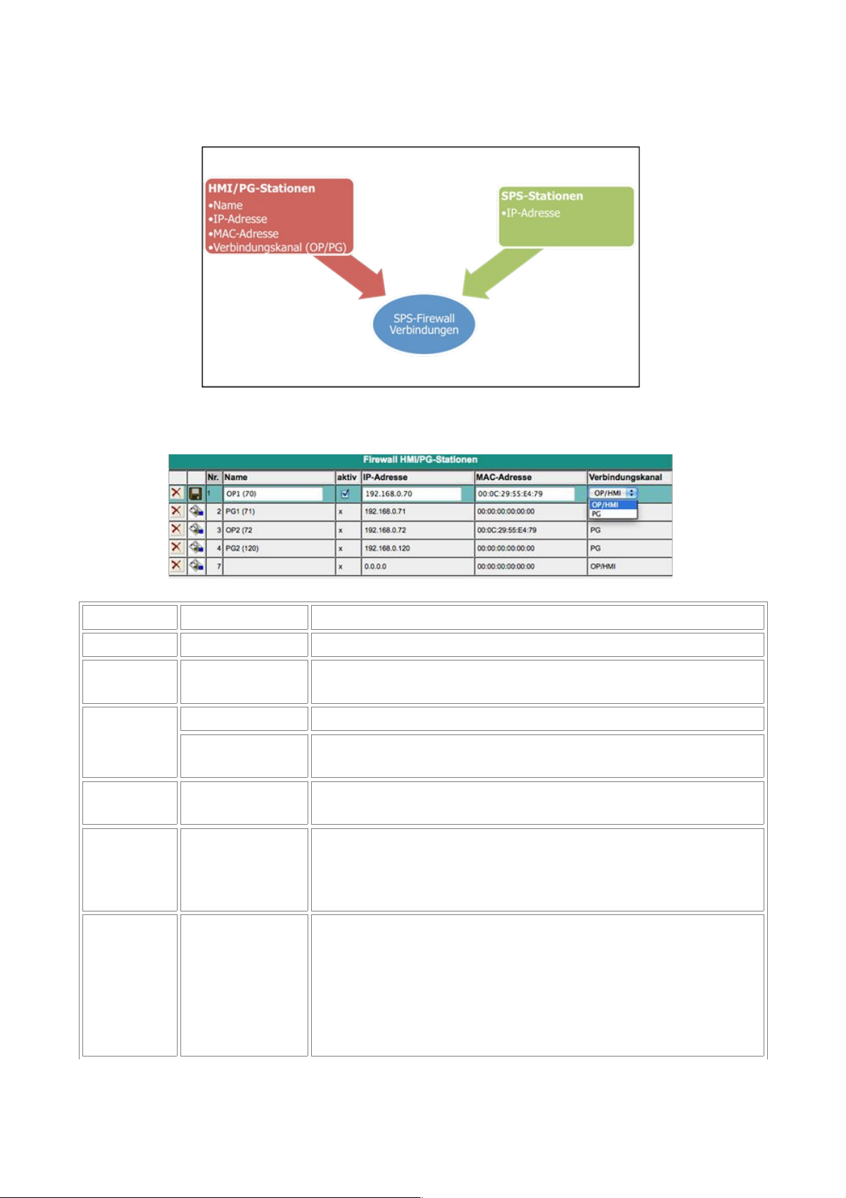
1.10 web user
Here the mask for entering the web user interface. Different permissions can be assigned per user.
Generall, only one user is allow to make "SU"-changes. U1 - U5 only can use the interface. In the
TeleRouter expansion modules "U1" - "U5" have more precisely specified operation rights.
Page 7 of 12 Handbook S7-Firewall
Page 8
1.11 S7 firewall settings
The SPS firewall connections consits of the HMI/PG station and the SPS station
1.12 entering of the HMI / PG station
parameters possible setting purpose
No. automatically ongoing number
name
freely entered by
the user
name oft the station
active
yes (x) connections with this station are processed by the firewall
no ()
connections with this station will not be processed, i. e. they are
blocked
IP address
IP address of the
HMI / PG device
identification of the sender input necessarily necessary
MAC
address
MAC address of
the HMI / PG
device
Identifies the HMI / PG addition on the MAC address.
00:00:00:00:00:00 means that the MAC address is not cheked.
When equal to 0, the MAC address of the station must match to
the input.
connecting
conduit
used channel of
communication
In Simantic S/ PG and OP channels are available. This channel is
used as an additional characteristic for identification of the
sender. On each of two channels in both PG and OP functions are
possible. HMIs / WinCC etc. typical use OP channels. The
Siemens PG software always uses the PG channel. Unfortunately,
different software on the market is in use, which does not have
the know-how to set this channel. To figure that out, you have to
Handbook S7-Firewall Page 8 of 12
Page 9
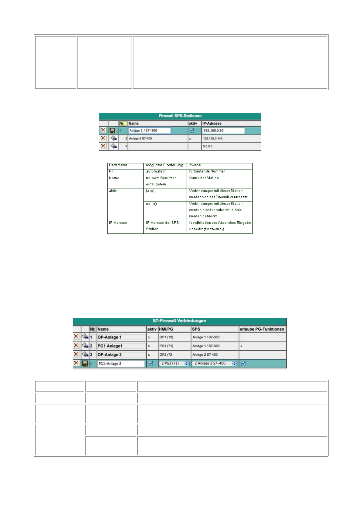
check the logfile.
A reasonable HMI software, respectively, the corresponding
software driver provides the adjustability of this channel. Should
for example from the same computer the PG and HMI (IP / MAC
identicial to PG / HMI) running, remeans only the PG / OP
channel to identify the sender.
1.13 entering of the SPS station
1.14 entering of the S7 firewall connections
The connections are formed from the combination of HMI /PG station and SPS station. Each HMI /
SPS station can be used repeatedly. By changing from MAC or IP address, you must only be chang
this in the HMI / PG station and SPS station. Every connection is organized to a connection rule. If
"allow PG full-function" is selected, this connection has full access. In the future, this access is to
be divided in more detail (read / write defined blocks, SPS start / stop, general reset, read / write
system data).
parameters possible setting purpose
No. automatically ongoing number
name
freely entered by
user
name of the connection
also serves as a "link" to open and edit the control script
active
yes (x) connections with this station are processed by the firewall
no ()
connections with this station will not be processed, i. e. they are
blocked
Page 9 of 12 Handbook S7-Firewall
Page 10
allow PG full
function
yes (x)
This connection is a PG connection and can be perform all
functions
no ()
This connection is a limited connection. There are only accesses
to the shared functional and data areas allows, as definied in the
accompanying control script.
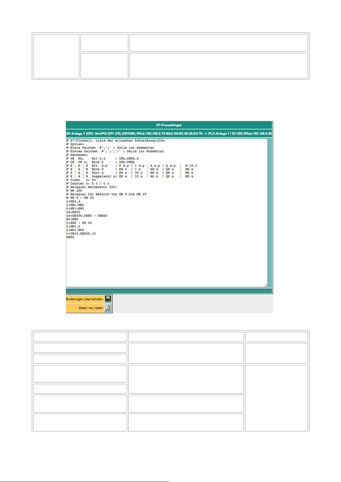
1.15 The rulescript
In the rule script, the data areas or possible requests for that connection are defined. The script can
be accessed via the link of the name of the connection.
syntax of the rule script
first signs function rest of the line
#
the line is a comment free text
//
(no sign it follows the same
operand / area)
The following area is only to read (read
only)
operand / area (see
below)
r:
w:
The following area is only to write (write
only)
rw:
The following area is to read and to write
(read/write)
Handbook S7-Firewall Page 10 of 12
Page 11
In a control line, a single operand, or I a area entered. Example for the inputting of indiviudal
operands: (Source from Siemens STEP-S7 PG-Software)
allowed operands data type
example (mnemonic
german)
example (mnemonic
english)
Input | output | flag BYTE EB 1 | AB 10 | MB 10 IB 1 | QB 10 | MB 10
Input | output | flag WORD EW 1 | AW 10 | MW 10 IW 1 | QW 10 | MW 10
Input | output | flag DWORD ED 1 | AD 10 | MD 10 ID 1 | QD 10 | MD 10
peripheral (Input |
Output)
BYTE PB 0 | PEB 0 | PAB 1 PB 0 | PIB 0 | PQB 1
peripheral (Input |
Output)
WORD PW 0 | PEW 0 | PAW 1 PW 0 | PIW 0 | PQW 1
peripheral (Input |
Output)
DWORD PW 0 | PED 0 | PAD 1 PD 0 | PID 0 | PQD 1
times TIMER T 1 T 1
counter COUNTER Z 1 C 1
data block BOOL DB1.DBX 1.0 DB1.DBX 1.0
data block BYTE DB1.DBB 1 DB1.DBB 1
data block WORD DB1.DBW 1 DB1.DBW 1
data block DWORD DB1.DBD 1 DB1.DBD 1
Hint: The inputting of "DB0. .." is not allowed because internal use.
Example for entering areas with Number of Units: from Memory bit 60, 10 byte: MB60, 10
from DB10, word 2, 5 words: DB10.DW2, 5
After the decimal point follows the desired number of units (depending on the address type, BOOL,
BYTE, WORD, DWORD)
For example, the input areas of "from" - "to" byte 70 to byte 200: 70 MB - 200 MB
Output A Output 10.2 to 14.7: A 10.2 - A14.7
Easy to start with operands, -, specify the end operands (end address). The end address is
included!
2 Technical data
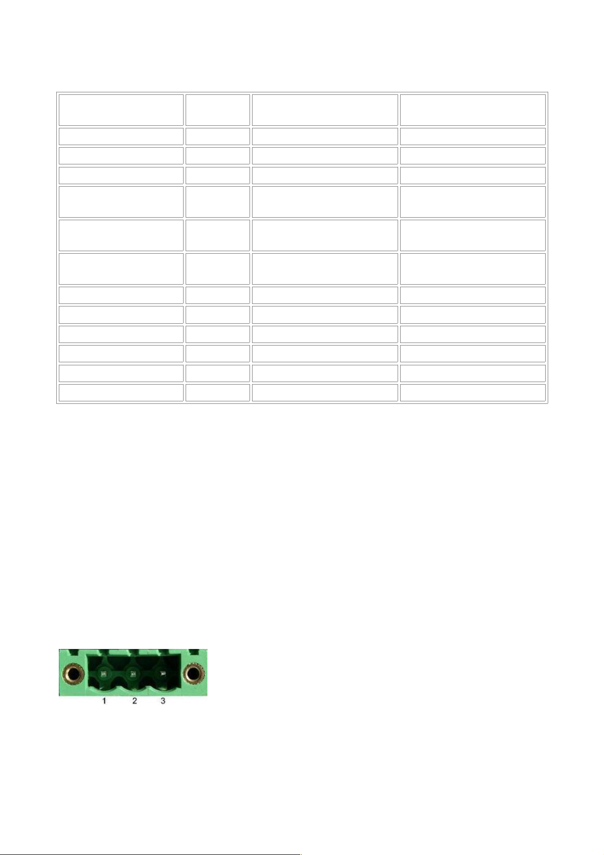
2.1 pin assignment power supply
Pin number Short form Designation Direction
1 P24V 24V DC voltage input
2 PE earthing input
3 M24V mass input
Page 11 of 12 Handbook S7-Firewall
Page 12

2.2 Pinning Ethernet
Pin no. Short name Notation Direction
1 TX + receive line + Out
2 TX – receive line – Out
3 RX + send line + In
6 RX – send line – In
Handbook S7-Firewall Page 12 of 12
 Loading...