

Page 1
User Manual
Physik Instrumente (PI) GmbH & Co. KG, Auf der Roemerstrasse 1, 76228 Karlsruhe, Germany
Phone +49 721 4846
S310T0001, valid for S-310, S-311, S-314, S-315 and S-316
KSch, 10/15/2019
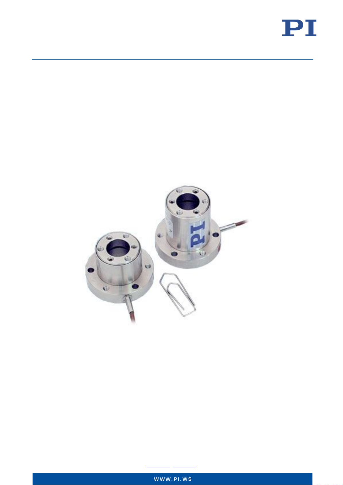
S-310 and S-314 Lift Platforms, and S-311,
S-315 and S-316 Lift and Tip/Tilt Platforms,
with Clear Aperture
Page 2

User Manual
Physik Instrumente (PI) GmbH & Co. KG, Auf der Roemerstrasse 1, 76228 Karlsruhe, Germany Page 2 / 36
Phone +49 721 4846
S310T0001, valid for S-310, S-311, S-314, S-315 and S-316
KSch, 10/15/2019
Contents
About this Document 4
Symbols and Typographic Conventions ............................................................................................................... 4
Other Applicable Documents .............................................................................................................................. 5
Downloading Manuals ......................................................................................................................................... 5
Safety 6
Intended Use ....................................................................................................................................................... 6
General Safety Instructions ................................................................................................................................. 7
Organizational Measures ..................................................................................................................................... 7
Product Description 7
Model Overview .................................................................................................................................................. 7
Product View ....................................................................................................................................................... 8
Product Labeling .................................................................................................................................................. 9
Scope of Delivery ............................................................................................................................................... 10
Suitable Electronics ........................................................................................................................................... 11
S-310.10, S-314.10 ........................................................................................................................................................ 11
S-311.10, S-315.10 ........................................................................................................................................................ 11
S-316.10 ........................................................................................................................................................................ 11
S-316.10H ...................................................................................................................................................................... 12
Control ............................................................................................................................................................... 12
Dynamic Behavior .............................................................................................................................................. 15
Calculating Moments of Inertia for Mirror and Mirror Mount ..................................................................................... 15
Calculating the Resonant Frequency of the Tip/Tilt Platform ....................................................................................... 17
Installation 19
General Notes on Installation ............................................................................................................................ 19
Grounding the S-31x .......................................................................................................................................... 20
Attaching the Mirror onto the S-31x ................................................................................................................. 21
Mounting the S-31x ........................................................................................................................................... 24
Connecting the S-31x to the Electronics............................................................................................................ 25
Start-Up and Operation 26
General Notes on Start-Up and Operation ........................................................................................................ 26
Starting Up and Operating the S-31x ................................................................................................................. 27
Discharging the S-31x ........................................................................................................................................ 27
-0, Fax +49 721 4846-1019, Email [email protected], www.pi.ws
Page 3

User Manual
Physik Instrumente (PI) GmbH & Co. KG, Auf der Roemerstrasse 1, 76228 Karlsruhe, Germany Page 3 / 36
Phone +49 721 4846
S310T0001, valid for S-310, S-311, S-314, S-315 and S-316
KSch, 10/15/2019
Maintenance 28
Cleaning the S-31x 28
Customer Service 29
Technical Data 29
Data Table .......................................................................................................................................................... 29
Maximum Ratings .............................................................................................................................................. 31
Ambient Conditions and Classifications ............................................................................................................ 32
Dimensions 33
Pin Assignment 34
Voltage Connection of S-31x.10 ........................................................................................................................ 34
Sensor Connection of S-316.10 ......................................................................................................................... 34
Voltage and Sensor Connection of S-316.10H ................................................................................................... 34
Old Equipment Disposal 36
EU Declaration of Conformity 36
-0, Fax +49 721 4846-1019, Email [email protected], www.pi.ws
Page 4
User Manual
Physik Instrumente (PI) GmbH & Co. KG, Auf der Roemerstrasse 1, 76228 Karlsruhe, Germany Page 4 / 36
Phone +49 721 4846
S310T0001, valid for S-310, S-311, S-314, S-315 and S-316
KSch, 10/15/2019
About this Document
This user manual contains information necessary for the intended use of the S-31x platforms. It
assumes that the reader has a fundamental understanding of basic servo systems as well as
motion control concepts and applicable safety procedures.
This user manual is valid for the following products:
S-310.10 lift platform
S-314.10 lift platform
S-311.10 lift and tip/tilt platform
S-315.10 lift and tip/tilt platform
S-316.10 and S-316.10H lift and tip/tilt platforms
Symbols and Typographic Conventions
CAUTION
Dangerous situation
If not avoided, the dangerous situation will result in minor injury.
Actions to take to avoid the situation.
NOTICE
Dangerous situation
If not avoided, the dangerous situation will result in damage to the equipment.
Actions to take to avoid the situation.
INFORMATION
Information for easier handling, tricks, tips, etc.
The following symbols and markings are used in the user manuals of PI:
Symbol Meaning
1.
2.
Action consisting of one or several steps whose sequential order is
S. 5 Cross-reference to page 5
-0, Fax +49 721 4846-1019, Email [email protected], www.pi.ws
Action consisting of several steps whose sequential order must be
observed
irrelevant
List item
Page 5
User Manual
Physik Instrumente (PI) GmbH & Co. KG, Auf der Roemerstrasse 1, 76228 Karlsruhe, Germany Page 5 / 36
Phone +49 721 4846
website after
S310T0001, valid for S-310, S-311, S-314, S-315 and S-316
KSch, 10/15/2019
Warning signs affixed to the product that refer to detailed information
in this document.
Other Applicable Documents
Product Document
E-727.3SD/E-727.3SDA digital multi-channel piezo controllers
for SGS
E-509.S3 sensor/servo controller module PZ77E user manual
E-503.00S piezo amplifier module PZ62E user manual
E-505.00 piezo amplifier module
E-501.00 9.5’’ chassis for modular piezo controller system
E-500.00 19" chassis for modular piezo controller system,
1 to 3 Channels
E-518.I3 interface module E518T0001 technical note,
E-610.S0 piezo controller/amplifier PZ70E user manual
E-625.SR piezo servo controller for strain gauge sensors PZ167E user manual
The current versions of the user manuals are available for download on our website.
Downloading Manuals
INFORMATION
E727T0005 technical note
PZ214E user manual
If a manual is missing or problems occur with downloading:
Contact our customer service department (p. 29).
INFORMATION
For products that are supplied with software (CD in the scope of delivery), access to the
manuals is protected by a password. Protected manuals are only displayed on the
entering the password.
The password is included on the CD of the product.
For products with CD: Identify the password
1. Insert the product CD into the PC drive.
2. Switch to the Manuals directory on the CD.
3. In the Manuals directory, open the Release News (file including releasenews in the file
name).
4. Find the user name and the password in the section "User login for software download"
in the Release News.
-0, Fax +49 721 4846-1019, Email [email protected], www.pi.ws
Page 6

User Manual
Physik Instrumente (PI) GmbH & Co. KG, Auf der Roemerstrasse 1, 76228 Karlsruhe, Germany Page 6 / 36
Phone +49 721 4846
S310T0001, valid for S-310, S-311, S-314, S-315 and S-316
KSch, 10/15/2019
Downloading Manuals
1. Open the website www.pi.ws.
2. If access to the manuals is protected by a password:
a) Click Login.
b) Log in with the user name and password.
3. Click Search.
4. Enter the product number up to the period (e.g., P-882) or the product family (e.g.,
PICMA® Bender) into the search field.
5. Click Start search or press the Enter key.
6. Open the corresponding product detail page in the list of search results:
a) If necessary: Scroll down the list.
b) If necessary: Click Load more results at the end of the list.
7. Scroll down to the Downloads section on the product detail page.
8. Click the desired manual and save it to the hard disk of your PC or to a data storage
Safety
Intended Use
Both S-310 and S-314 platforms provide motion along the Z axis, whereas S-311, S-315 and
S-316 offer tip/tilt motion additionally. For details regarding travel ranges refer to “Model
Overview” (p. 7).
Based on its design and realization, an S-31x platform is intended to position an optical
component, as for example, a mirror with a typical load of 3 g to 6.5 g.
The S-31x platform can be mounted horizontally or vertically. It is a laboratory device as defined
by DIN EN 61010-1. It is intended to be used in interior spaces and in an environment which is
free of dirt, oil and lubricants.
The intended use of the S-31x platform is only possible in combination with suitable electronics
that is available from PI.
c) Click the corresponding product in the list.
The manuals are displayed under Documentation.
medium.
-0, Fax +49 721 4846-1019, Email [email protected], www.pi.ws
Page 7

User Manual
Physik Instrumente (PI) GmbH & Co. KG, Auf der Roemerstrasse 1, 76228 Karlsruhe, Germany Page 7 / 36
Phone +49 721 4846
S310T0001, valid for S-310, S-311, S-314, S-315 and S-316
KSch, 10/15/2019
General Safety Instructions
The S-31x is built according to state-of-the-art technology and recognized safety standards.
Improper use can result in personal injury and/or damage to the S-31x.
Only use the S-31x for its intended purpose, and only use it if it is in a good working order.
Read the user manual.
Immediately eliminate any faults and malfunctions that are likely to affect safety.
The operator is responsible for the correct installation and operation of the S-31x.
Organizational Measures
User manual
Always keep this user manual available with the S-31x.
The latest versions of the user manuals are available for download (p. 5) on our website.
Add all information from the manufacturer to the user manual, for example supplements
or technical notes.
If you give the S-31x to other users, also include this user manual as well as other relevant
information provided by the manufacturer.
Only use the device on the basis of the complete user manual. Missing information due to
an incomplete user manual can result in minor injury and damage to equipment.
Only install and operate the S-31x after you have read and understood this user manual.
Personnel qualification
The S-31x may only be installed, started up, operated, maintained, and cleaned by authorized
and appropriately qualified personnel.
Product Description
Model Overview
Model Description
S-310.10 Piezo actuator, clear aperture, 6 μm, LEMO connectors
S-311.10 Piezo Z/ tip/tilt platform, clear aperture, 600 μrad, 6 μm, LEMO connectors
S-314.10 Piezo actuator, clear aperture, 12 μm, LEMO connectors
S-315.10 Piezo Z/ tip/tilt platform, clear aperture, 1.2 mrad, 12 μm, LEMO connectors
S-316.10 Piezo Z/ tip/tilt platform, clear aperture, 1.2 mrad, 12 μm, SGS, LEMO
connectors
S-316.10H Piezo Z/ tip/tilt platform, clear aperture, 1.2 mrad, 12 μm, SGS,
Sub-D 37-pin (m)
-0, Fax +49 721 4846-1019, Email [email protected], www.pi.ws
Page 8
User Manual
Physik Instrumente (PI) GmbH & Co. KG, Auf der Roemerstrasse 1, 76228 Karlsruhe, Germany Page 8 / 36
Phone +49 721 4846
S310T0001, valid for S-310, S-311, S-314, S-315 and S-316
KSch, 10/15/2019
INFORMATION
The open-loop models (S-310 to S-315) are ideal for applications where the position is
controlled by an external loop based on data provided by a sensor (e.g. quad cell, CCD chip).
Product View
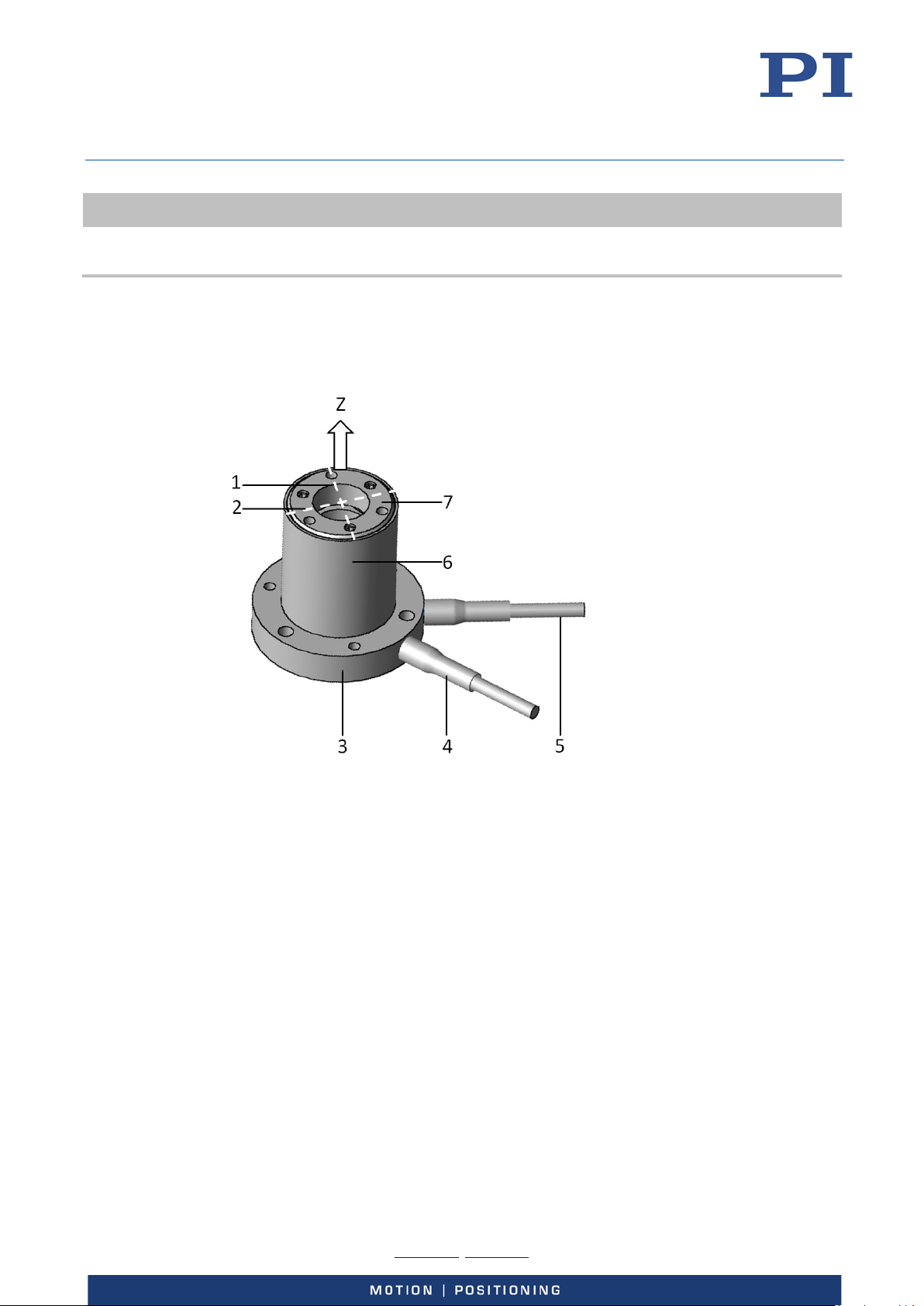
Figure 1: Example view of an S-316.10H
1 Axis X (corresponds to channel 1 on the E-727.3SD/A controller)*
2 Axis Y (corresponds to channel 2 on the E-727.3SD/A controller)*
3 Base body
4 Piezo voltage cable
5 Sensor cable (only S-316)
6 Housing
7 Motion platform with aperture
* The assignment of the axes X and Y in Figure 1 only applies under the following conditions:
It applies to the S-311, S-315, and S-316 models
This lift and tip/tilt platform was calibrated at PI with electronics that can perform
coordinate transformation (E-727.3SD/A)
Tilting is not possible with the S-310 and S-314 models.
If electronics are used that cannot perform coordinate transformation (e.g. E-509.S3 with
E-503.00), the user must determine the assignment of axes himself and perform coordinate
transformation separately.
-0, Fax +49 721 4846-1019, Email [email protected], www.pi.ws
Page 9
User Manual
Physik Instrumente (PI) GmbH & Co. KG, Auf der Roemerstrasse 1, 76228 Karlsruhe, Germany Page 9 / 36
Phone +49 721 4846
S310T0001, valid for S-310, S-311, S-314, S-315 and S-316
KSch, 10/15/2019
Product Labeling
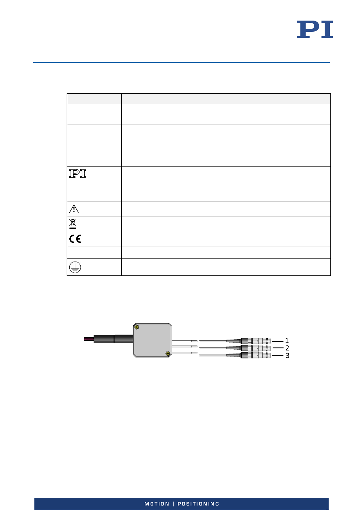
Labeling Description
S-316.10H
Product name (example), the characters following the period refer to the
model
Serial number (example), individual for each S-31x
Meaning of the places (counting from left):
116010244
1 = internal information
2 and 3 = year of manufacture
4 to 9 = consecutive numbers
Country of origin:
Germany
Manufacturer's logo
Country of origin
Warning sign "Observe manual!"
Old equipment disposal (p. 36)
CE conformity mark
WWW.PI.WS Manufacturer's address (website)
Symbol for the protective earth conductor
S-31x.10: Labeling of the LEMO connections
Figure 2: LEMO connections of the models without sensor
1 Piezo connection labeled PZT1
2 Piezo connection labeled PZT2
3 Piezo connection labeled PZT3
-0, Fax +49 721 4846-1019, Email [email protected], www.pi.ws
Page 10
User Manual
Physik Instrumente (PI) GmbH & Co. KG, Auf der Roemerstrasse 1, 76228 Karlsruhe, Germany Page 10 / 36
Phone +49 721 4846
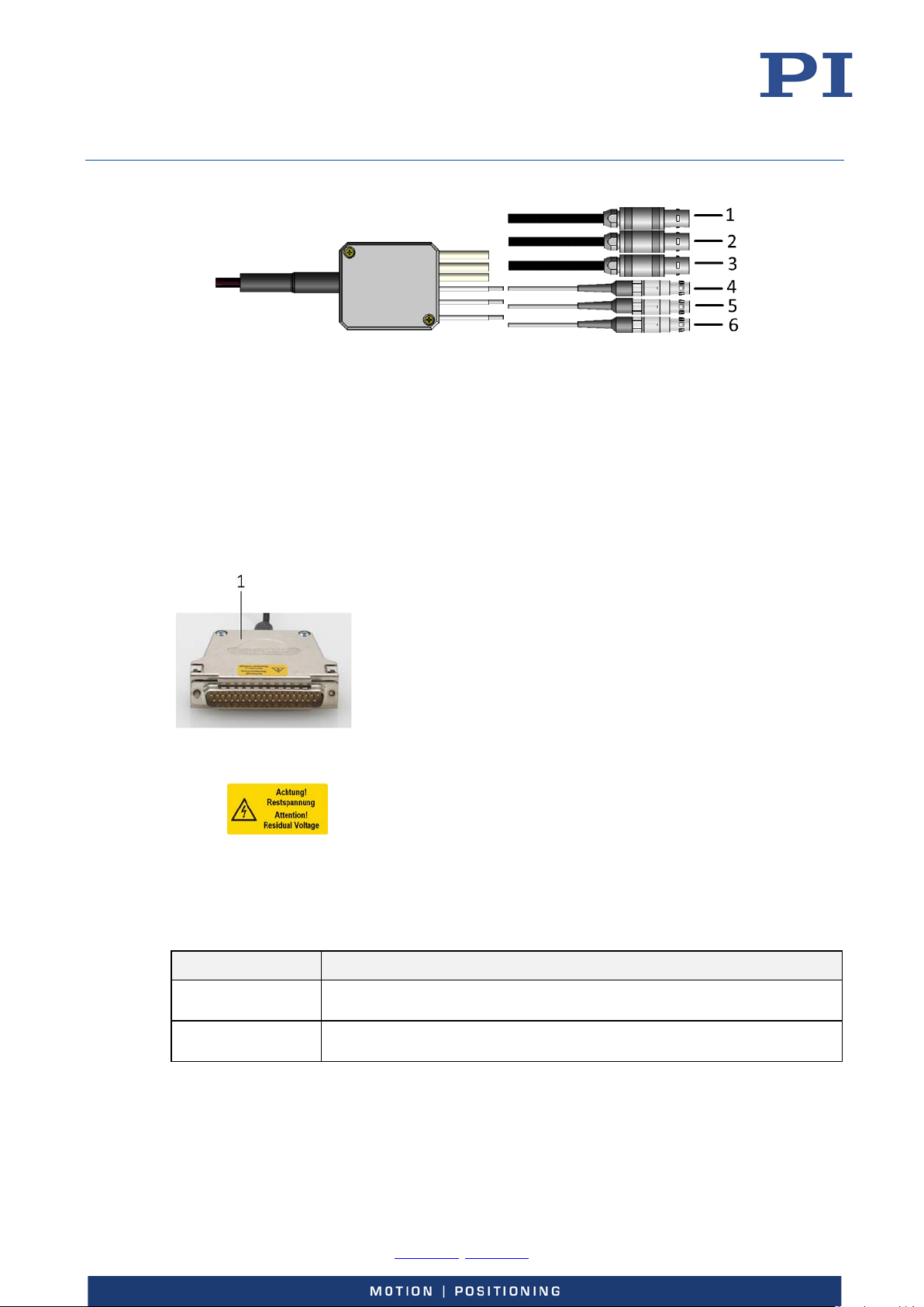
CH1
S310T0001, valid for S-310, S-311, S-314, S-315 and S-316
KSch, 10/15/2019
Figure 3: LEMO connections of S-316.10, model with sensor
1 Sensor connection labeled
2 Sensor connection labeled CH2
3 Sensor connection labeled CH3
4 Piezo connection labeled PZT1
5 Piezo connection labeled PZT2
6 Piezo connection labeled PZT3
S-316.10H: Labeling of the Sub-D 37 (m) connector
Figure 4: Sub-D 37 (m) connector on the connection cable of the S-316.10H
1
Scope of Delivery
Item ID Components
S-31x Lift platform or lift and tip/tilt platform as specified in the order
Warning sign "Residual Voltage": Notice of risk of electric shock
(p. 7)
PZ277EK Short instructions for S-3xx piezo tip/tilt platforms
-0, Fax +49 721 4846-1019, Email [email protected], www.pi.ws
Page 11

User Manual
Physik Instrumente (PI) GmbH & Co. KG, Auf der Roemerstrasse 1, 76228 Karlsruhe, Germany Page 11 / 36
Phone +49 721 4846
S310T0001, valid for S-310, S-311, S-314, S-315 and S-316
KSch, 10/15/2019
Suitable Electronics
S-310.10, S-314.10
Amplifier Dimensions Interfaces
E-505.00 piezo amplifier module,
2 A, -30 to 130 V, 1 channel
E-610.00 piezo amplifier, 1 channel,
OEM module, -30 to 130 V
E-500.00 19" chassis for
modular piezo controller
system, 1 to 3 channels
7 HP / 3RU -
Optional: E-518.I3 interface
module, 3 channels, TCP/IP, USB
and RS-232 interfaces
S-311.10, S-315.10
Amplifier Dimensions Interfaces
E-503.00 piezo amplifier module,
-30 to 130 V, 3 channels
3 x E-505.00 piezo amplifier module,
2 A, -30 to 130 V, 1 channel
3 x E-610.00 piezo amplifier,
1 channel, OEM module,
-30 to 130 V
E-501.00 9½'' chassis for
modular piezo controller
system, 1 to 3 channels
E-500.00 19" chassis for
modular piezo controller
system, 1 to 3 channels
7 HP / 3RU -
Optional: E-518.I3 interface
module, 3 channels, TCP/IP, USB
and RS-232 interfaces
Optional: E-518.I3 interface
module, 3 channels, TCP/IP, USB
and RS-232 interfaces
S-316.10
Controller Amplifier Dimensions Interfaces
E-509.S3 sensor / piezo
servo-control module,
strain gauge sensors,
3 channels
E-509.S3 sensor / piezo
servo-control module,
strain gauge sensors,
3 channels
3 x E-610.S0 piezo controller/amplifier,
OEM module, 1 channel, -30 to 130 V, SGS
sensor
3 x E-625.SR piezo amplifier / servo controller ,
1 channel, -30 to 130 V,
SGS sensor, USB, RS-232
E-503.00 piezo
amplifier module,
-30 to 130 V,
3 channels
3 x E-505.00 piezo
amplifier module,
2 A, -30 to 130 V,
1 channel
E-501.00 9½'' chassis for
modular piezo controller
system,
1 to 3 channels
E-500.00 19" chassis for
modular piezo controller
system,
1 to 3 channels
7 HP / 3 RU -
205 mm × 105 mm ×
60 mm
Optional: E-518.I3 interface
module, 3 channels, TCP/IP,
USB and RS-232 interfaces
Optional: E-518.I3 interface
module, 3 channels, TCP/IP,
USB and RS-232 interfaces
-
-0, Fax +49 721 4846-1019, Email [email protected], www.pi.ws
Page 12

User Manual
Physik Instrumente (PI) GmbH & Co. KG, Auf der Roemerstrasse 1, 76228 Karlsruhe, Germany Page 12 / 36
Phone +49 721 4846
S310T0001, valid for S-310, S-311, S-314, S-315 and S-316
KSch, 10/15/2019
S-316.10H
Controller Dimensions Interfaces
E-727.3SD digital multi-channel piezo
controller, 3 channels, -30 to 130 V,
sub-D 37 socket, strain gauge sensors
E-727.3SDA digital multi-channel piezo
controller, 3 channels, -30 to 130 V,
sub-D 37 socket, strain gauge sensors, analog
inputs
Control
S-310 to S-316 tilt platforms are equipped with three low-voltage (0 to 100 V) piezo actuators
spaced at 120° intervals.
With the S-310 and S-314 platforms only motion in Z axis is possible. Their three PZTs are
electrically connected in parallel.
In addition, the S-311, S-315 and S-316 platforms provide tip/tilt motion. With these platforms
all three PZTs can be driven individually.
Control of the tip/tilt versions is complicated because expansion of an individual piezo actuator
can affect both θX and θY rotation. Therefore the linear travel in Z and the tip/tilt angles in θX
and θY are interdependent.
221 mm × 240.10 mm ×
116.60 mm
221 mm × 240.10 mm ×
116.60 mm
-
-
External coordinate transformation (software or hardware) is required to allow platform
position commands in θX and θY coordinates.
An example for how to calculate the linear travel and the tip/tilt angles depending on the linear
displacements of the piezo actuators is given below.
Example calculation of linear travel and tip/tilt angles
There are many ways to define the axes and tip/tilt angles. The definitions you use will depend
on the geometry of your application.
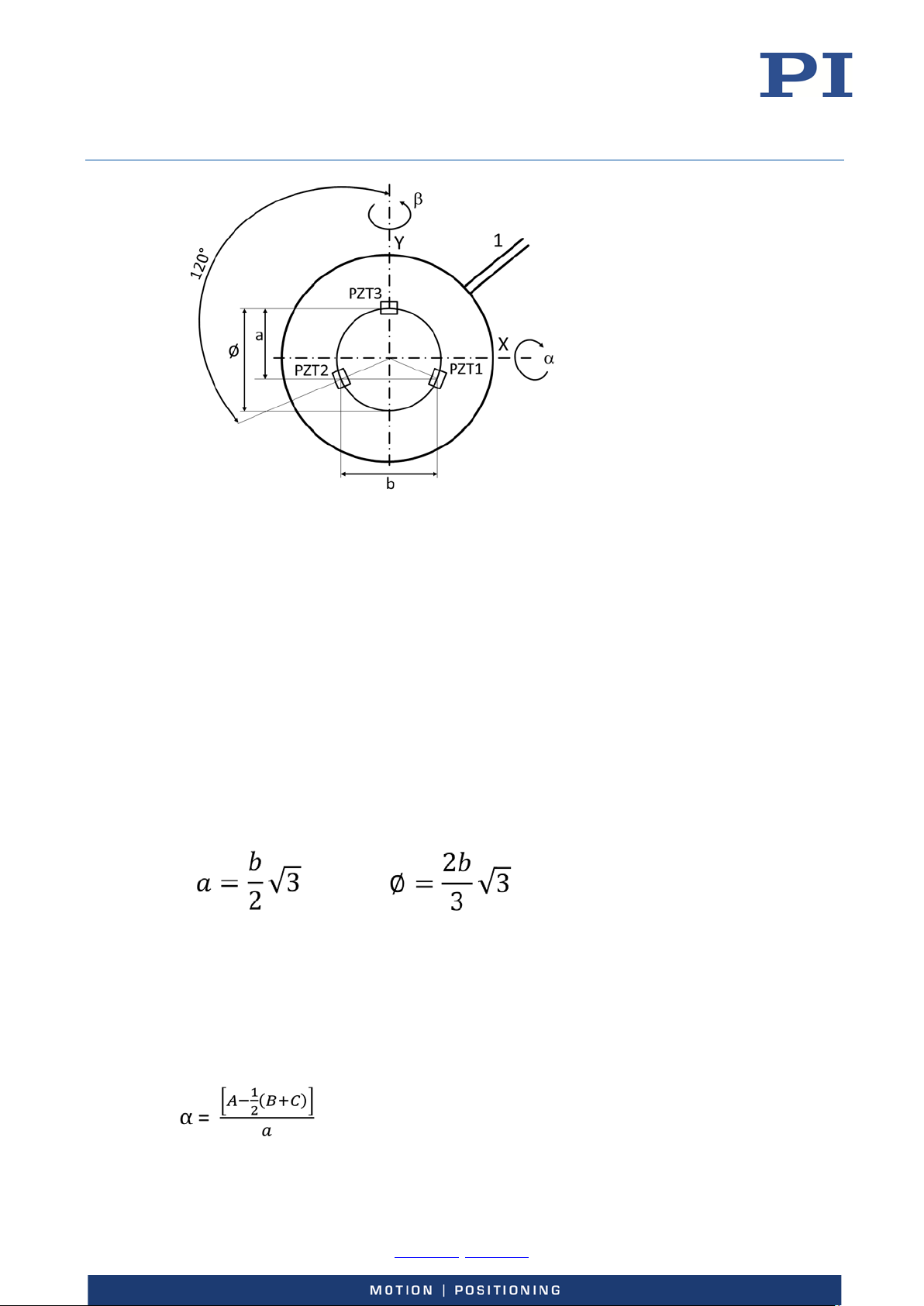
The geometry shown in Figure 5 and the calculation of distance a and the diameter Ø are based
on a system with the Y-axis passing through one of the actuators (designated PZT3).
See also “Product View” on p. 8 for more information on assignment of axes.
-0, Fax +49 721 4846-1019, Email [email protected], www.pi.ws
Page 13
User Manual
Physik Instrumente (PI) GmbH & Co. KG, Auf der Roemerstrasse 1, 76228 Karlsruhe, Germany Page 13 / 36
Phone +49 721 4846
S310T0001, valid for S-310, S-311, S-314, S-315 and S-316
KSch, 10/15/2019
Figure 5: Triple-piezo-drive tip/tilt platform geometry, viewed from above.
1 Cable exit
X X axis as defined by the calibration at PI
Y Y axis as defined by the calibration at PI
PZT1 to PZT3 Piezo actuators
a Distance between PZT3 and PZT2/PZT1 along the Y axis
b Distance between PZT1 and PZT2
Ø Diameter of circle of centers of the piezo actuators
α Tilt angle around X axis, depending on linear displacement of the
piezo actuators
β Tilt angle around Y axis, depending on linear displacement of the
piezo actuators
Calculation of distance a and diameter Ø
Calculation of tip/tilt angles α and β and linear travel in Z
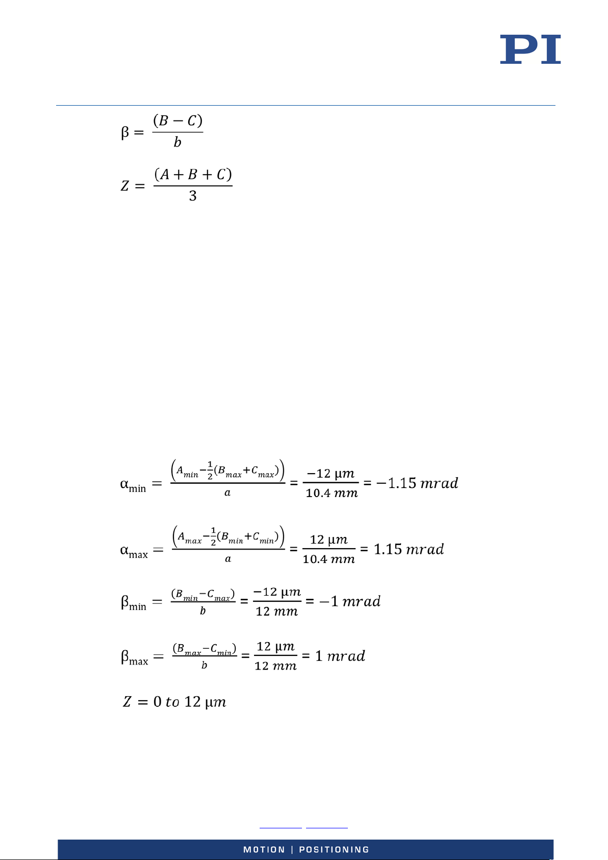
The following formulas show the relationship between the displacement of each piezo actuator
(from the bottom limit of the travel range = extension at 0 V) and the tip/tilt angles (in radians).
The formulas use the sin α = α approximation, making it valid for small angles, covering the full
travel range of the lift and tip/tilt platform.
-0, Fax +49 721 4846-1019, Email [email protected], www.pi.ws
Page 14
User Manual
Physik Instrumente (PI) GmbH & Co. KG, Auf der Roemerstrasse 1, 76228 Karlsruhe, Germany Page 14 / 36
Phone +49 721 4846
S310T0001, valid for S-310, S-311, S-314, S-315 and S-316
KSch, 10/15/2019
with:
α = Tip/tilt angle in θX, measured around axis X as defined by the calibration at PI [mrad]
β = Tip/tilt angle in θY, measured around axis Y as defined by the calibration at PI [mrad]
A = Linear displacement of PZT3 [µm]
B = Linear displacement of PZT2 [µm]
C = Linear displacement of PZT1 [µm]
Z = Linear displacement of the platform center (i.e. travel in Z axis)
Example calculation for S-315 and S-316 lift and tip/tilt platforms
Ø = 13.9 mm
a = 10.4 mm
b = 12.0 mm
A, B, C: 0 to 12 µm (range of linear displacement of the piezo actuators)
-0, Fax +49 721 4846-1019, Email [email protected], www.pi.ws
Page 15
User Manual
Physik Instrumente (PI) GmbH & Co. KG, Auf der Roemerstrasse 1, 76228 Karlsruhe, Germany Page 15 / 36
Phone +49 721 4846
S310T0001, valid for S-310, S-311, S-314, S-315 and S-316
KSch, 10/15/2019
Dynamic Behavior
The maximum operating frequency of a piezo tip/tilt platform depends on the following factors:
Bandwidth of amplifier, controller, and sensor
Resonant frequency of the tip/tilt platform including mirror and where appropriate,
mirror mount
The resonant frequency is estimated in two steps:
a) Calculating the moments of inertia for mirror and mirror mount (p. 15)
b) Calculating (p. 17) resonant frequency of the tip/tilt platform including mirror and
Calculating Moments of Inertia for Mirror and Mirror Mount
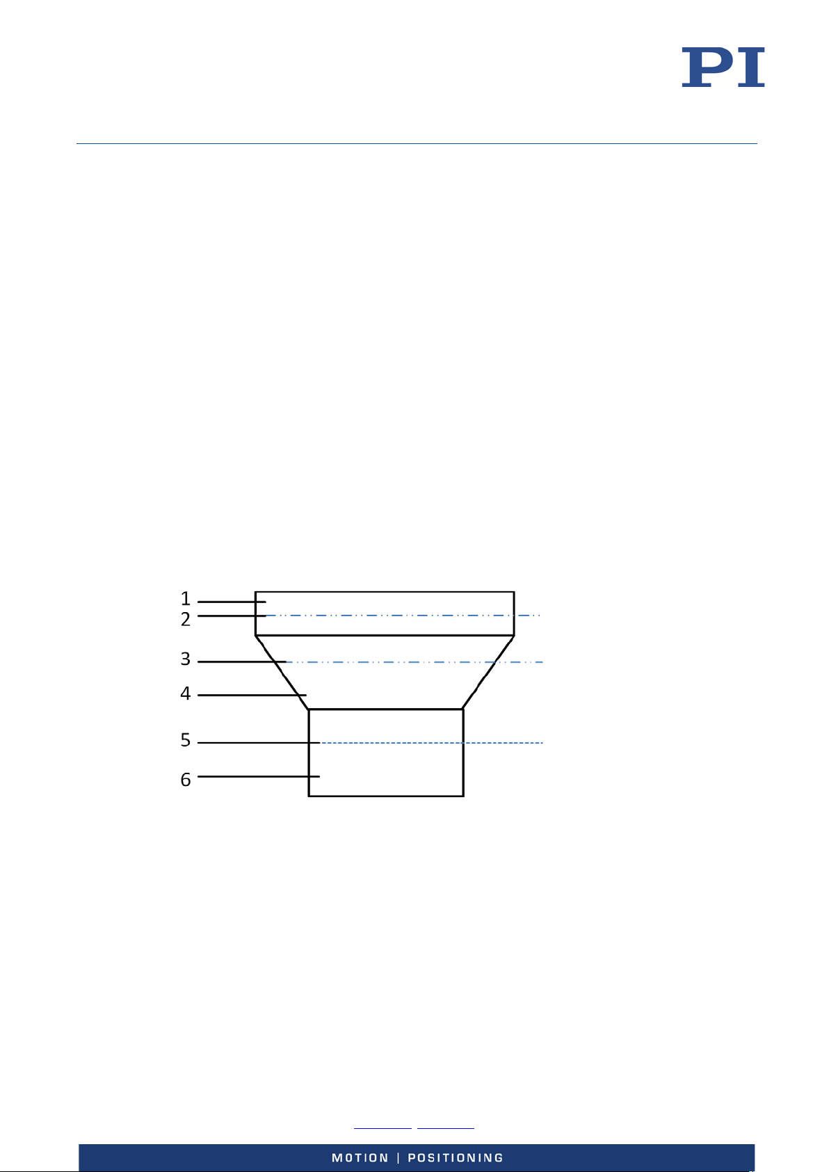
Calculating the distance from the axis through the center of gravity of the mirror to the rotational axis
mirror mount.
Before the moment of inertia of the mirror is calculated, it is necessary to calculate the distance
from the axis through the center of gravity of the mirror to the rotational axis of the platform.
When a mirror mount is used, it must be included in the calculation.
Figure 6: Example diagram: Platform with mirror mount and mirror
1 Mirror
2 Axis through the center of gravity of the mirror
3 Axis through the center of gravity of the mirror mount
4 Mirror mount (example of a geometry)
5 Axis through the pivot point of the platform of the S-335 ("rotational axis")
6 Platform
-0, Fax +49 721 4846-1019, Email [email protected], www.pi.ws
Page 16
User Manual
Physik Instrumente (PI) GmbH & Co. KG, Auf der Roemerstrasse 1, 76228 Karlsruhe, Germany Page 16 / 36
Phone +49 721 4846
S310T0001, valid for S-310, S-311, S-314, S-315 and S-316
KSch, 10/15/2019
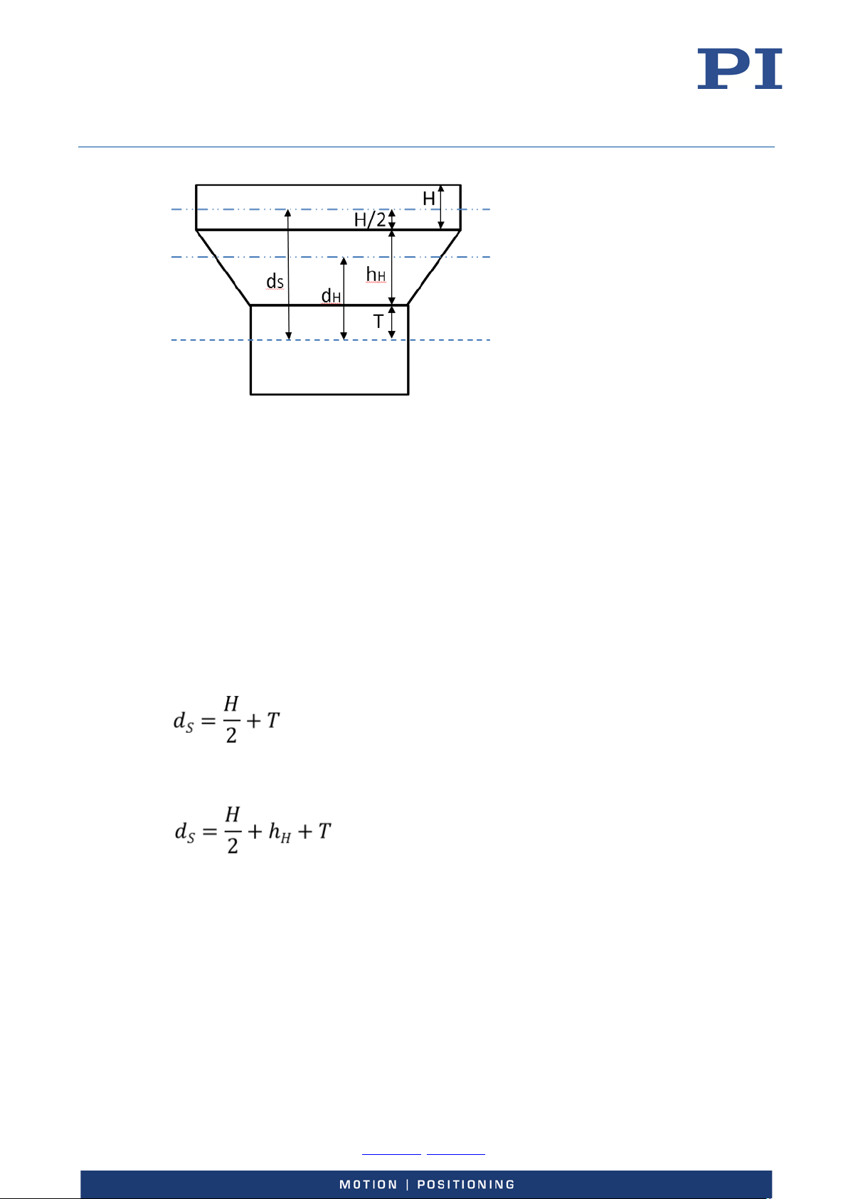
Figure 7: Example diagram: Platform with mirror mount and mirror; here with variables required for
calculating the moments of inertia
d
Distance from the axis through the center of gravity of the mirror to the rotational axis
S
d
Distance from the axis through the center of gravity of the mirror mount to the rotational axis
H
H/2 Half the mirror thickness
h
Thickness of the mirror mount
H
T Distance from the rotational axis to the platform surface (see "Data Table" (p. 29))
H Mirror thickness
Formula for calculating the distance from the axis through the center of gravity of the mirror to
the rotational axis of the platform:
When a mirror is attached without a mirror mount:
When a mirror is attached with a mirror mount:
with:
d
= Distance from the axis through the center of gravity of the mirror to the rotational axis
S
[mm]
H = Mirror thickness [mm]
h
= Thickness of the mirror mount [mm]
H
T = Distance from the rotational axis to the platform surface [mm], see "Data Table" (p. 29)
-0, Fax +49 721 4846-1019, Email [email protected], www.pi.ws
Page 17

User Manual
Physik Instrumente (PI) GmbH & Co. KG, Auf der Roemerstrasse 1, 76228 Karlsruhe, Germany Page 17 / 36
Phone +49 721 4846
S310T0001, valid for S-310, S-311, S-314, S-315 and S-316
KSch, 10/15/2019
Calculating the moment of inertia of the mirror
Formula for calculating the moment of inertia of a rotationally symmetric mirror:
Formula for calculating the moment of inertia of a rectangular mirror:
with:
I
= Moment of inertia of the mirror, in relation to the rotational axis [g•mm2]
S,P
m
= Mirror mass [g]
S
R = Mirror radius [mm]
L = Mirror length perpendicular to the rotational axis [mm]
H = Mirror thickness [mm]
d
= Distance from the axis through the center of gravity of the mirror to the rotational axis
S
[mm]; for calculation see separate formulas (p. 15)
Calculating the moment of inertia of the mirror mount
with:
I
= Moment of inertia of the mirror mount, in relation to the rotational axis [g•mm2]
H,P
I
= Moment of inertia of the mirror mount, dependent on the geometry of the mirror mount
H
2
[g•mm
m
d
axis of the platform [mm], see above illustration (p. 15)
]
= Mass of the mirror mount [g]
H
= Distance from the axis through the center of gravity of the mirror mount to the rotational
H
Calculating the Resonant Frequency of the Tip/Tilt Platform
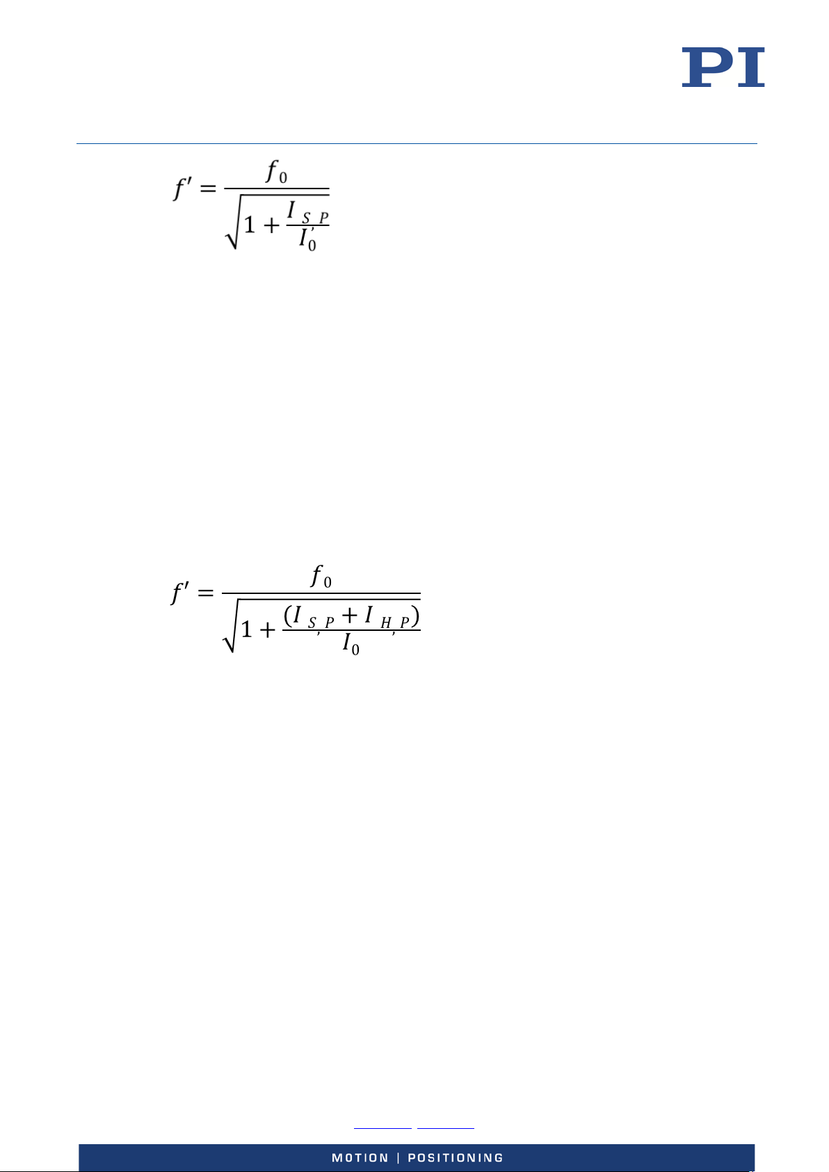
Mirror without mirror mount
When the mirror is mounted without a mirror mount, the resonant frequency of the system is
calculated with the following formula:
-0, Fax +49 721 4846-1019, Email [email protected], www.pi.ws
Page 18
User Manual
Physik Instrumente (PI) GmbH & Co. KG, Auf der Roemerstrasse 1, 76228 Karlsruhe, Germany Page 18 / 36
Phone +49 721 4846
S310T0001, valid for S-310, S-311, S-314, S-315 and S-316
KSch, 10/15/2019
with:
f' = Resonant frequency of the S-335 with mirror [Hz]
f
= Resonant frequency of the unloaded S-335 [Hz]; see "Data Table" (p. 29)
0
I
= Moment of inertia of the platform of the S-335 [g•mm2], see "Data Table" (p. 29)
0
I
= Moment of inertia of the mirror, in relation to the rotational axis, [g•mm2]; calculation see
S,P
separate formulas (p. 17)
Mirror with mirror mount
When the mirror is mounted with a mirror mount, the resonant frequency of the tip/tilt
platform is calculated with the following formula:
with:
f' = Resonant frequency of the S-335 with mirror and mirror mount [Hz]
f
= Resonant frequency of the unloaded S-335 [Hz], see "Data Table" (p. 29)
0
I
= Moment of inertia of the platform of the S-335 [g•mm2], see "Data Table" (p. 29)
0
I
= Moment of inertia of the mirror, in relation to the rotational axis, [g•mm2]; for calculation
S,P
see separate formulas (p. 17)
I
= Moment of inertia of the mirror mount, in relation to the rotational axis, [g•mm2];
H,P
calculation see separate formula (p. 17)
Further information on dynamic or static operation can be found in the PI catalog (CAT 130), in
the section "Fundamentals of Piezo Technology". The catalog can be downloaded from our
website http://www.pi.ws under Service > Downloads > Catalogs, Brochures & Certificates.
-0, Fax +49 721 4846-1019, Email [email protected], www.pi.ws
Page 19
User Manual
Physik Instrumente (PI) GmbH & Co. KG, Auf der Roemerstrasse 1, 76228 Karlsruhe, Germany Page 19 / 36
Phone +49 721 4846
S310T0001, valid for S-310, S-311, S-314, S-315 and S-316
KSch, 10/15/2019
Installation
General Notes on Installation
CAUTION
Dangerous voltage and residual charge on piezo actuators!
The S-31x is driven by piezo actuators. Mechanical shock, temperature changes and
compressive stresses will cause high voltages to be developed. Touching the contacts of the
S-31x can lead to minor injuries. In addition, the piezo actuators can be destroyed by an abrupt
contraction.
Do not open the S-31x.
Discharge the piezo actuators of the S-31x before installation:
Connect the S-31x to the switched-off PI controller for 10 seconds.
Do not pull out the connector from the electronics during operation.
NOTICE
Unsuitable cables!
Unsuitable cables can damage the electronics.
Only use cables from PI for connecting the S-31x to the electronics.
NOTICE
Warping of the S-31x due to mounting on uneven surfaces!
Mounting the S-31x on an uneven surface can warp the S-31x. Warping reduces the accuracy.
Mount the S-31x on an even surface. The recommended evenness of the surface
is ≤30 µm.
For applications with large temperature changes:
Only mount the S-31x on surfaces that have the same or similar thermal expansion
properties as the S-31x.
INFORMATION
Extended cables can affect the performance of the S-31x.
If you need longer cables, contact our customer service department (p. 29).
-0, Fax +49 721 4846-1019, Email [email protected], www.pi.ws
Page 20
User Manual
Physik Instrumente (PI) GmbH & Co. KG, Auf der Roemerstrasse 1, 76228 Karlsruhe, Germany Page 20 / 36
Phone +49 721 4846
S310T0001, valid for S-310, S-311, S-314, S-315 and S-316
KSch, 10/15/2019
Grounding the S-31x
The S-31x does not feature a separate protective earth connection but must be connected
conductively with a surface that is connected to a protective earth conductor.
Requirements
You have read and understood the safety precautions (p. 19).
Tools and accessories
Screws and alignment pins of suitable length, for details see “Mounting the S-31x”
(p. 24)
Suitable tool
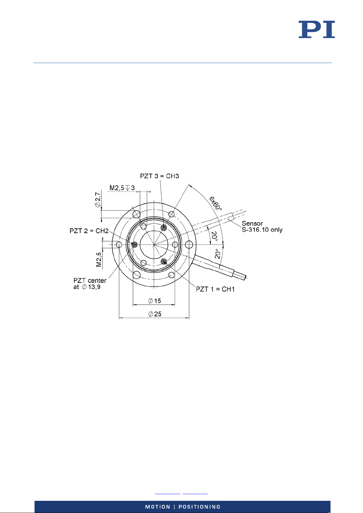
Figure 8: The three M2.5 through holes and the through holes with a Ø of 2.7 mm are to be used to
mount the S-31x onto a surface that is connected to a protective earth conductive
Grounding the S-31x
Attach the S-31x to a surface which is connected to a protective earth conductor:
1. Make sure that the contact resistance is <0.1 ohm at 25 A at all connection points
relevant for mounting the protective earth conductor.
2. Tighten the used M2.5 screws to the surface using the threaded mounting holes with at
least three rotations and a torque of 0.6 Nm.
For further details refer to “Mounting the S-31x” (p. 24)
-0, Fax +49 721 4846-1019, Email [email protected], www.pi.ws
Page 21
User Manual
Physik Instrumente (PI) GmbH & Co. KG, Auf der Roemerstrasse 1, 76228 Karlsruhe, Germany Page 21 / 36
Phone +49 721 4846
1
2
S310T0001, valid for S-310, S-311, S-314, S-315 and S-316
KSch, 10/15/2019
Attaching the Mirror onto the S-31x
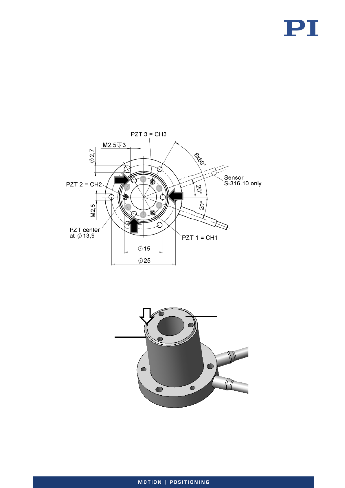
You can attach the mirror to the S-31x by two ways:
Glue the mirror onto a mirror mount that can be mounted onto the platform using the
three M2.5 mounting holes
Glue the mirror directly onto the platform
Figure 9: Gray areas mark where glue can be applied onto the S-31x, black arrows mark where to
mount a mirror mount
Figure 10: The arrow marks where adhesive must not enter
1 Housing
2 Motion platform
-0, Fax +49 721 4846-1019, Email [email protected], www.pi.ws
Page 22
User Manual
Physik Instrumente (PI) GmbH & Co. KG, Auf der Roemerstrasse 1, 76228 Karlsruhe, Germany Page 22 / 36
Phone +49 721 4846
S310T0001, valid for S-310, S-311, S-314, S-315 and S-316
KSch, 10/15/2019
NOTICE
Excessively long screws!
The S-31x can be damaged by screws that are inserted too deeply.
When selecting the screw length, observe the thickness of the mirror mount that is to be
mounted.
NOTICE
Entering adhesive reduces accuracy!
When the mirror is glued directly onto the platform: adhesive that runs into the gap between
the platform and the housing of the S-31x reduces the accuracy (see figure above).
Ensure that adhesive cannot run into the gap between platform and housing, for example,
by using a suitable mask that allows for punctiform applying of the adhesive.
INFORMATION
Before gluing any mirror you should consider some important aspects:
How flat does the mirror need to be? The greater the required flatness, the more care
needs to be taken. This is primarily a matter of experience.
Materials match: The platform of the S-31x is made of stainless steel 1.4305. Ideally, the
mirror should have an identical thermal coefficient of expansion CTE). The platform of the
S-31x has a CTE of 16 ppm/K.
Choose an adhesive that may be cured at room temperature (less stress is induced while
drying/curing) and that shrinks as little as possible during the process.
Requirements
You have read and understood the safety precautions (p. 19).
The S-31x is not connected to the controller.
Tools and accessories
Suitable mirror
When the mirror is mounted using a mirror mount:
− Suitable mirror mount
− 3 M2.5 screws of suitable length
− Suitable tool to fix mirror mount
When the mirror is glued onto the platform:
− Suitable adhesive, see above
− Dosing apparatus
− Option: Suitable positioning device for applying the adhesive
Cotton swab
Isopropanol
-0, Fax +49 721 4846-1019, Email [email protected], www.pi.ws
Page 23

User Manual
Physik Instrumente (PI) GmbH & Co. KG, Auf der Roemerstrasse 1, 76228 Karlsruhe, Germany Page 23 / 36
Phone +49 721 4846
S310T0001, valid for S-310, S-311, S-314, S-315 and S-316
KSch, 10/15/2019
Powder-free gloves
Attaching the mirror onto the S-31x using a mirror mount
1. Attach the mirror mount onto the S-31x:
a) Optional: Align the mirror mount onto the platform using the 3 threaded pins.
b) Mount the mirror mount onto the platform of the S-31x using the three M2.5
screws.
Pay attention to a maximum screw-in depth of 3 mm.
Maximum torque: 0.6 Nm
2. Glue the mirror onto the mirror mount:
a) Insert a sufficient amount of adhesive on the mirror mount with a dosing apparatus.
The adhesive must not be spoiled.
b) Align the mirror on the mirror mount.
c) Carefully and briefly press the mirror onto the mirror mount with a cotton swab.
d) If necessary, remove the adhesive residue with a cotton swab and isopropanol.
e) Allow the adhesive to harden according to the instructions of the adhesive
manufacturer.
Glueing the mirror onto the S-31x
1. Apply a sufficient amount of adhesive onto the platform:
a) If you use a mask for applying the adhesive: carefully align the mask on the
platform of the S-31x and fix it in a suitable manner.
b) Apply a suitable amount of adhesive to three suitable points; see above figure. Only
apply a pinhead-sized amount to each point.
c) If you use a positioning device for applying the adhesive: remove it.
2. Glue the mirror onto the platform:
a) Carefully place the mirror in a suitable orientation on the platform. Avoid touching
the mirror surface.
b) Carefully and briefly press the mirror onto the motion platform with a cotton swab.
c) If necessary, remove the adhesive residue with a cotton swab and isopropanol.
d) Allow the adhesive to harden according to the instructions of the adhesive
manufacturer.
-0, Fax +49 721 4846-1019, Email [email protected], www.pi.ws
Page 24
User Manual
Physik Instrumente (PI) GmbH & Co. KG, Auf der Roemerstrasse 1, 76228 Karlsruhe, Germany Page 24 / 36
Phone +49 721 4846
S310T0001, valid for S-310, S-311, S-314, S-315 and S-316
KSch, 10/15/2019
Mounting the S-31x
The S-31x can be mounted in any orientation. It can be mounted either from above or from
below.
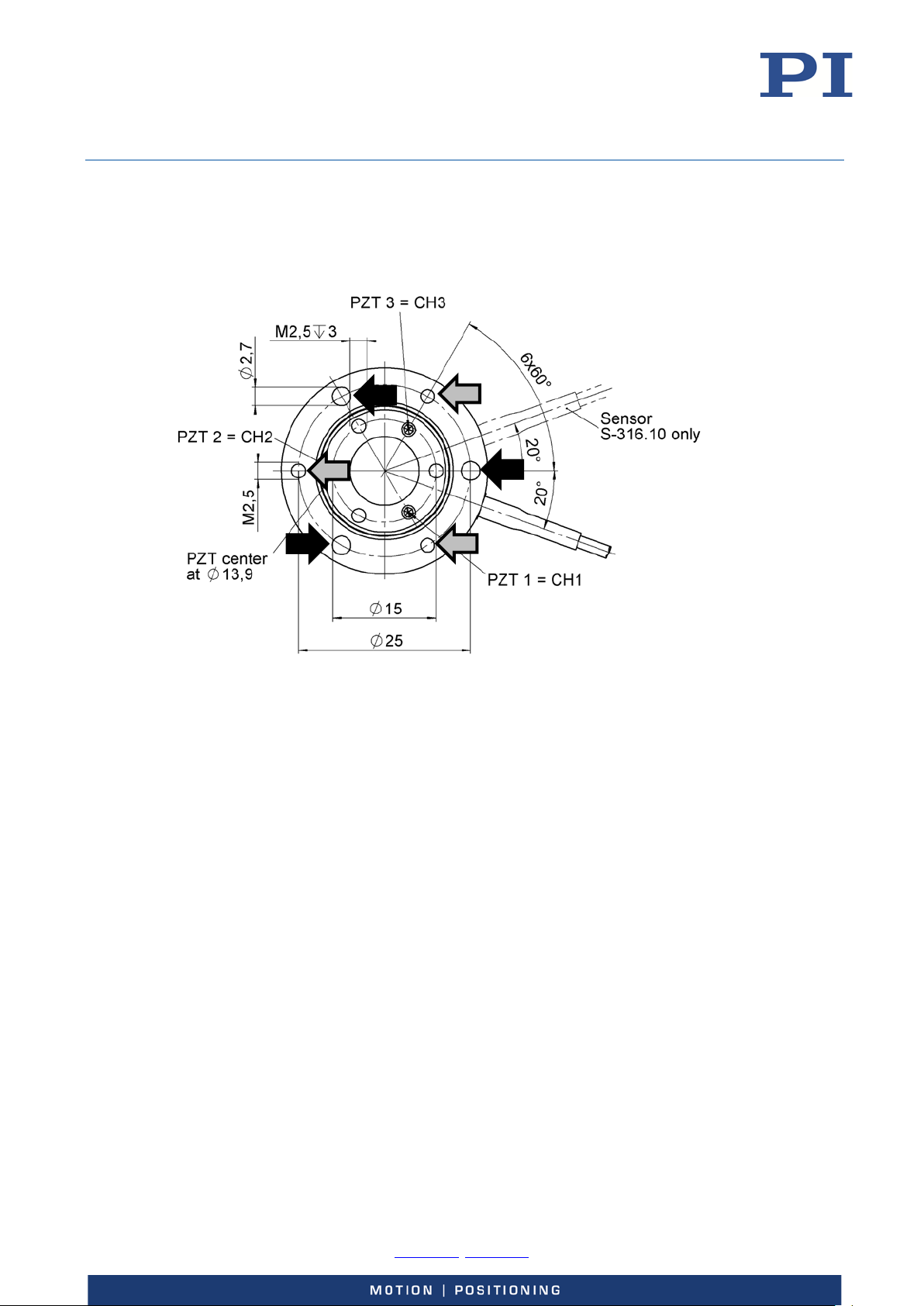
Figure 11: Arrows indicate where to mount the S-31x
Black arrows: Through holes for M2.5 screws, for mounting from above
Gray arrows: Threaded holes for M2.5 screws, for mounting from below
Tools and accessories
6 x M2.5 screws of appropriate length
Suitable tool
Suitable surface
Requirements
You have provided a suitable installation environment:
− The surface is connected to a protective earth conductor
− The flatness of the surface is ≤30 µm.
The S-31x is not connected to the controller
Mounting the S-31x
Mount the S-31x using the mounting holes labeled by arrows, see Figure 11.
-0, Fax +49 721 4846-1019, Email [email protected], www.pi.ws
Page 25

User Manual
Physik Instrumente (PI) GmbH & Co. KG, Auf der Roemerstrasse 1, 76228 Karlsruhe, Germany Page 25 / 36
Phone +49 721 4846
S310T0001, valid for S-310, S-311, S-314, S-315 and S-316
KSch, 10/15/2019
Connecting the S-31x to the Electronics
Requirements
You have read and understood the safety precautions (p. 19).
You have installed a suitable electronics (p. Fehler! Textmarke nicht definiert.).
You have read and understood the user manual of the electronics.
The electronics is switched off.
Connecting the S-316.10H to the E-727.xSD controller
1. Plug the connector of the S-316.10H into the corresponding socket of the controller
(see user manual of the controller).
2. Use the integrated screws to secure the connection against accidental disconnection.
Connecting the S-31x.10 to E-50x modules
1. Connect the piezo connectors of the S-31x.10 with the piezo amplifier modules as
follows.
If you use an E-503.00S module:
− PZT1 to PZT for channel 1 (CH1)
Only with S-311, S-315 and S-316:
− PZT2 to PZT for channel 2 (CH2)
− PZT3 to PZT for channel 3 (CH3)
If you use three E-505.00 modules for variable voltages:
− PZT1 to PZT of an E-505.00 module
Only with S-311, S-315 and S-316:
− PZT2 to PZT of the second E-505.00 module
− PZT3 to PZT of the third E-505.00 module
2. Connect the sensor connections of the S-316.10 to the E-509.S3 servo-controller
module as follows:
− CH1 to SENSOR for channel 1 (SERVO 1)
− CH2 to SENSOR for channel 2 (SERVO 2)
− CH3 to SENSOR for channel 3 (SERVO 3)
-0, Fax +49 721 4846-1019, Email [email protected], www.pi.ws
Page 26
User Manual
Physik Instrumente (PI) GmbH & Co. KG, Auf der Roemerstrasse 1, 76228 Karlsruhe, Germany Page 26 / 36
Phone +49 721 4846
S310T0001, valid for S-310, S-311, S-314, S-315 and S-316
KSch, 10/15/2019
Start-Up and Operation
General Notes on Start-Up and Operation
CAUTION
Risk of electric shock if the protective earth conductor is not connected!
If a protective earth conductor is not or not properly connected, dangerous touch voltages can
occur on the S-31x in the case of malfunction or failure of the system. If touch voltages exist,
touching the S-31x can result in minor injury from electric shock.
Connect the S-31x to a protective earth conductor before start-up.
Do not remove the protective earth conductor during operation.
Use electrically conductive materials (e.g. screws and flat washers) for mounting the
protective earth conductor.
Make sure that the contact resistance is < 0.1 ohm at 25 A at all connection points relevant
for mounting the protective earth conductor.
If the protective earth conductor has to be temporarily removed (e.g. for modifications),
reconnect the S-31x to the protective earth conductor before starting it up again.
NOTICE
Destruction of the piezo actuator by electric flashovers!
The use of the S-31x in environments that increase the electrical conductivity can lead to the
destruction of the piezo actuator by electric flashovers. Electric flashovers can be caused by
moisture, high humidity, liquids and conductive materials such as metal dust. In addition,
electric flashovers can also occur in certain air pressure ranges due to the increased
conductivity of the air.
Avoid operating the S-31x in environments that can increase the electric conductivity.
Only operate the S-31x within the permissible ambient conditions and classifications
(p. 32).
NOTICE
Destruction of the piezo actuator by continuously high voltage!
The constant application of high voltage to piezo actuators can lead to leakage currents and
flashovers that destroy the ceramic.
If the S-31x is not used, but the controller is to remain switched on to ensure temperature
stability:
Set the piezo voltage to 0 V on the controller.
-0, Fax +49 721 4846-1019, Email [email protected], www.pi.ws
Page 27
User Manual
Physik Instrumente (PI) GmbH & Co. KG, Auf der Roemerstrasse 1, 76228 Karlsruhe, Germany Page 27 / 36
Phone +49 721 4846
S310T0001, valid for S-310, S-311, S-314, S-315 and S-316
KSch, 10/15/2019
NOTICE
Uncontrolled oscillation!
Oscillations can cause irreparable damage to the S-31x. Oscillations are indicated by a
humming and can result from the following causes:
The load and/or dynamics of operation differ too much from the calibration settings.
Note that any mass mounted on the platform will reduce the resonant frequency.
The S-31x is operated near its resonant frequency.
If you notice oscillations, stop the S-31x immediately.
INFORMATION
For maximum tilt range of the tip/tilt versions, the optimum zero tip/tilt position is when
all three piezo actuators are biased at 50 V.
Linear travel and tilt angle are interdependent (see “Control” on p. 12). The travel and
tip/tilt angles given in the data table (p. 29) refer to pure linear or pure angular motion.
INFORMATION
In dynamic applications it is important to avoid exceeding the power-output capability of the
amplifier. You can check this using the section “Continuous dynamic operation” (p. 60 -61) in
the PI catalog “Piezo Actuators” (CAT128).
The catalog can be downloaded from our website http://www.pi.ws under Service >
Downloads > Catalogs, Brochures & Certificates.
If required contact our customer service department (p. 29).
Starting Up and Operating the S-31x
Requirements
You have read and understood the following sections:
− Safety Precautions (p. 19)
− General Notes on Start-Up and Operation (p. 26)
Starting up and operating the S-31x
Follow the instructions in the manual of the used electronics for start-up and operation of
the S-31x.
Discharging the S-31x
The S-31x must be discharged in the following cases:
When the S-31x is not used but the controller remains switched on to ensure temperature
stability
-0, Fax +49 721 4846-1019, Email [email protected], www.pi.ws
Page 28
User Manual
Physik Instrumente (PI) GmbH & Co. KG, Auf der Roemerstrasse 1, 76228 Karlsruhe, Germany Page 28 / 36
Phone +49 721 4846
S310T0001, valid for S-310, S-311, S-314, S-315 and S-316
KSch, 10/15/2019
Before demounting (e.g. before cleaning and transport of the S-31x and for modifications
of the application)
Before pulling out the connector of the S-31x
Discharging the S-31x that is connected to the controller
If you are working in closed-loop operation:
1. Switch off the servo mode on the controller.
2. Set the piezo voltage to 0 V on the controller.
If you are working in open-loop operation:
Set the piezo voltage to 0 V on the controller.
Discharging the S-31x that is not connected to the controller
Connect the tip/tilt platform to the switched-off controller for 10 seconds.
Maintenance
NOTICE
Misalignment from loosening screws!
The S-31x is maintenance-free and precisely aligned.
Do not loosen any sealed screws on the S-31x.
Cleaning the S-31x
NOTICE
Cleaning can damage the S-31x!
When liquid enters the S-31x the integrated piezo actuators are destructed by electric
flashovers.
Ensure that no liquid can enter the S-31x.
Only clean the S-31x as described in the following section.
Requirements
You have discharged the piezo actuators of the S-31x.
You have disconnected the S-31x from the controller.
Cleaning the S-31x
Clean the surface of the S-31x with a towel that is lightly dampened with a mild
cleanser or disinfectant, with ethanol or with isopropanol.
Do not do any ultrasonic cleaning.
-0, Fax +49 721 4846-1019, Email [email protected], www.pi.ws
Page 29

User Manual
Physik Instrumente (PI) GmbH & Co. KG, Auf der Roemerstrasse 1, 76228 Karlsruhe, Germany Page 29 / 36
Phone +49 721 4846
S-310.10
S-314.10
S-311.10
S-315.10
S-316.10
Unit
Tolerance
Motion and positioning
Open-loop resolution
S310T0001, valid for S-310, S-311, S-314, S-315 and S-316
KSch, 10/15/2019
Customer Service
For inquiries and orders, contact your PI sales engineer or send us an e-mail ([email protected]).
If you have questions concerning your system, have the following information ready:
Product codes and serial numbers of all products in the system
Firmware version of the controller (if present)
Version of the driver or the software (if present)
Operating system on the PC (if present)
The latest versions of the relevant user manuals for your system are available for download on
our website (http://www.pi.ws).
Technical Data
Data Table
S-316.10H
Active axes Z Z Z, θX, θY Z, θX, θY Z, θX, θY
Integrated sensor - - - - SGS
Open-loop travel in Z
at 0 to 100 V
Open-loop tip/tilt angle,
0 to 100 V
Closed-loop travel in Z - - - - 12 µm
Closed-loop tip/tilt angle
Open-loop resolution
in Z
6 12 6 12 12 µm min.
- - 600 1200 1200 µrad min.
- - - - 1200 µrad
0.1 0.2 0.1 0.2 0.2 nm typ.
(+20 %/
-0 %)
(+20 %/
-0 %)
- - 0.02 0.05 0.05 µrad typ.
in θX, θY
Closed-loop resolution
in Z
Closed-loop resolution
in θX, θY
Linearity error - - - - 0.2 % typ.
-0, Fax +49 721 4846-1019, Email [email protected], www.pi.ws
- - - - 0.4 nm typ.
- - - - 0.1 µrad typ.
Page 30

User Manual
Physik Instrumente (PI) GmbH & Co. KG, Auf der Roemerstrasse 1, 76228 Karlsruhe, Germany Page 30 / 36
Phone +49 721 4846
Resonant frequency,
Drive properties
Miscellaneous
Cable length
S310T0001, valid for S-310, S-311, S-314, S-315 and S-316
KSch, 10/15/2019
S-310.10 S-314.10 S-311.10 S-315.10 S-316.10
Unit Tolerance
S-316.10H
Mechanical properties
Stiffness in Z 20 10 20 10 10 N/µm ±20 %
Resonant frequency,
9.5 5.5 9.5 5.5 5.5 kHz ±20 %
no load, in Z
Resonant frequency,
6.5 4.4 6.5 4.1 4.1 kHz ±20 %
under load (with 15 mm
x 4 mm glass mirror)
6.1 4.2 6.1 3.4 3.4 kHz ±20 %
under load (with 20 mm
x 4 mm glass mirror)
Gap from pivot point to
- - 5 5 5 mm ±1 mm
platform surface
Platform moment of
inertia
- - 150 150 150 g ×
mm²
±20 %
Ceramic type PICMA®
P-882
PICMA®
P-882
PICMA®
P-882
PICMA®
P-882
PICMA®
P-882
Electrical capacitance 0.39 0.93 0.39 (0.13
per axis)
0.93 (0.31
per axis)
0.93 (0.31
per axis)
µF ±20 %
Material Steel Steel Steel Steel Steel
Mass 0.053 0.055 0.045 0.055 0.055 kg ±5 %
2 2 2 2 2 m ±10 mm
Voltage connection LEMO LEMO LEMO LEMO S-316.10:
LEMO
S-310.10H:
Sub-D 37 (m)
Sensor connection - - - - S-316.10:
LEMO
S-310.10H:
Sub-D 37 (m)
Resolution of S-31xs is not limited by friction or stiction. Value given is noise equivalent motion
with E -503 amplifier.
Mechanical tilt, optical beam deflection is twice as large. For maximum tilt range, all three piezo
actuators must be biased at 50 V. Due to the parallel- kinematics design, linear travel and tilt
angle are interdependent. The values quoted here refer to pure linear / pure angular motion
(equations).
-0, Fax +49 721 4846-1019, Email [email protected], www.pi.ws
Page 31
User Manual
Physik Instrumente (PI) GmbH & Co. KG, Auf der Roemerstrasse 1, 76228 Karlsruhe, Germany Page 31 / 36
Phone +49 721 4846
S310T0001, valid for S-310, S-311, S-314, S-315 and S-316
KSch, 10/15/2019
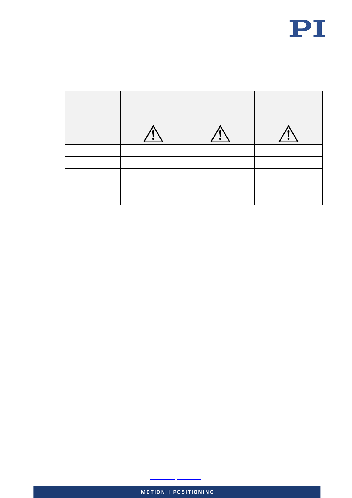
Maximum Ratings
Model
Maximum operating
voltage
Maximum operating
frequency (with 15 mm
x 4 mm glass mirror, at
100 Vpp) 1
Maximum power
consumption 2 (for all
axes, at 1 kHz)
S-310.10 0 to +100 V 1 kHz 6.39 W
S-314.10 0 to +100 V 1 kHz 12.81 W
S-311.10 0 to +100 V 1 kHz 2.13 W
S-315.10 0 to +100 V 1 kHz 4.27 W
S-316.10/.10H 0 to +100 V 1 kHz 4.27 W
1
To ensure stable operation, the maximum operating frequency is defined as approximately
1/3 of the mechanical resonant frequency.
2
The heat generated by the piezo actuator during dynamic operation limits the value for
maximum power consumption.
Details can be found online:
http://piceramic.com/piezo-technology/properties-piezo-actuators/electrical-operation.html
-0, Fax +49 721 4846-1019, Email [email protected], www.pi.ws
Page 32

User Manual
Physik Instrumente (PI) GmbH & Co. KG, Auf der Roemerstrasse 1, 76228 Karlsruhe, Germany Page 32 / 36
Phone +49 721 4846
S310T0001, valid for S-310, S-311, S-314, S-315 and S-316
KSch, 10/15/2019
Ambient Conditions and Classifications
Area of application For indoor use only
Maximum altitude 2000 m
Air pressure
Relative humidity
Operating temperature –20 °C to 80 °C
Storage temperature –20 °C to 80 °C
Transport temperature –25 °C to 85 °C
Overvoltage category II
Protection class I
Degree of pollution 1
Degree of protection according
to IEC 60529
1100 hPa to 0.1 hPa
(corresponds to roughly 825 Torr to 0.075 Torr)
Highest relative humidity 80 % for temperatures up
to 31 °C
Decreasing linearly to 50 % relative humidity at 40 °C
IP20
-0, Fax +49 721 4846-1019, Email [email protected], www.pi.ws
Page 33
User Manual
Physik Instrumente (PI) GmbH & Co. KG, Auf der Roemerstrasse 1, 76228 Karlsruhe, Germany Page 33 / 36
Phone +49 721 4846
S310T0001, valid for S-310, S-311, S-314, S-315 and S-316
KSch, 10/15/2019
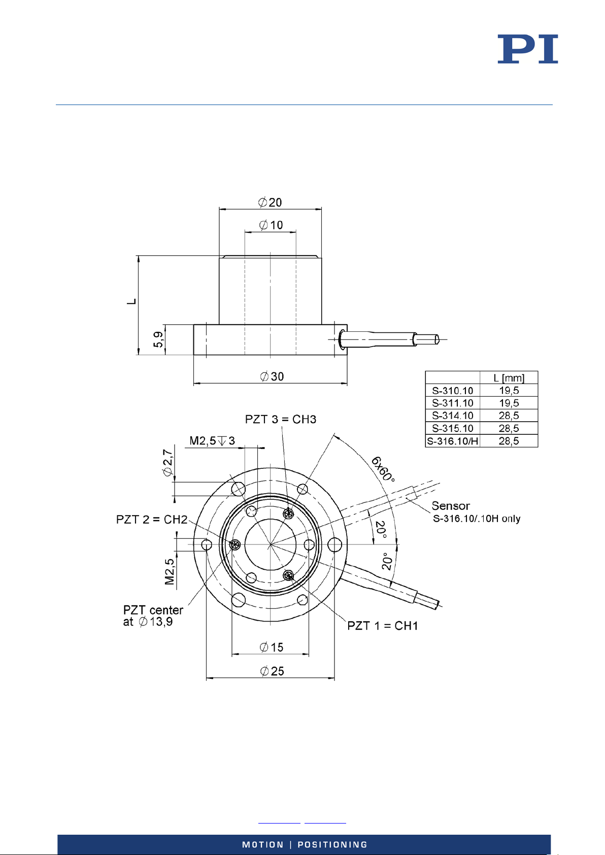
Dimensions
Dimensions in mm. Note that the decimal places are separated by a comma in the drawings.
Figure 12: S-31x
-0, Fax +49 721 4846-1019, Email [email protected], www.pi.ws
Page 34
User Manual
Physik Instrumente (PI) GmbH & Co. KG, Auf der Roemerstrasse 1, 76228 Karlsruhe, Germany Page 34 / 36
Phone +49 721 4846
S310T0001, valid for S-310, S-311, S-314, S-315 and S-316
KSch, 10/15/2019
Pin Assignment
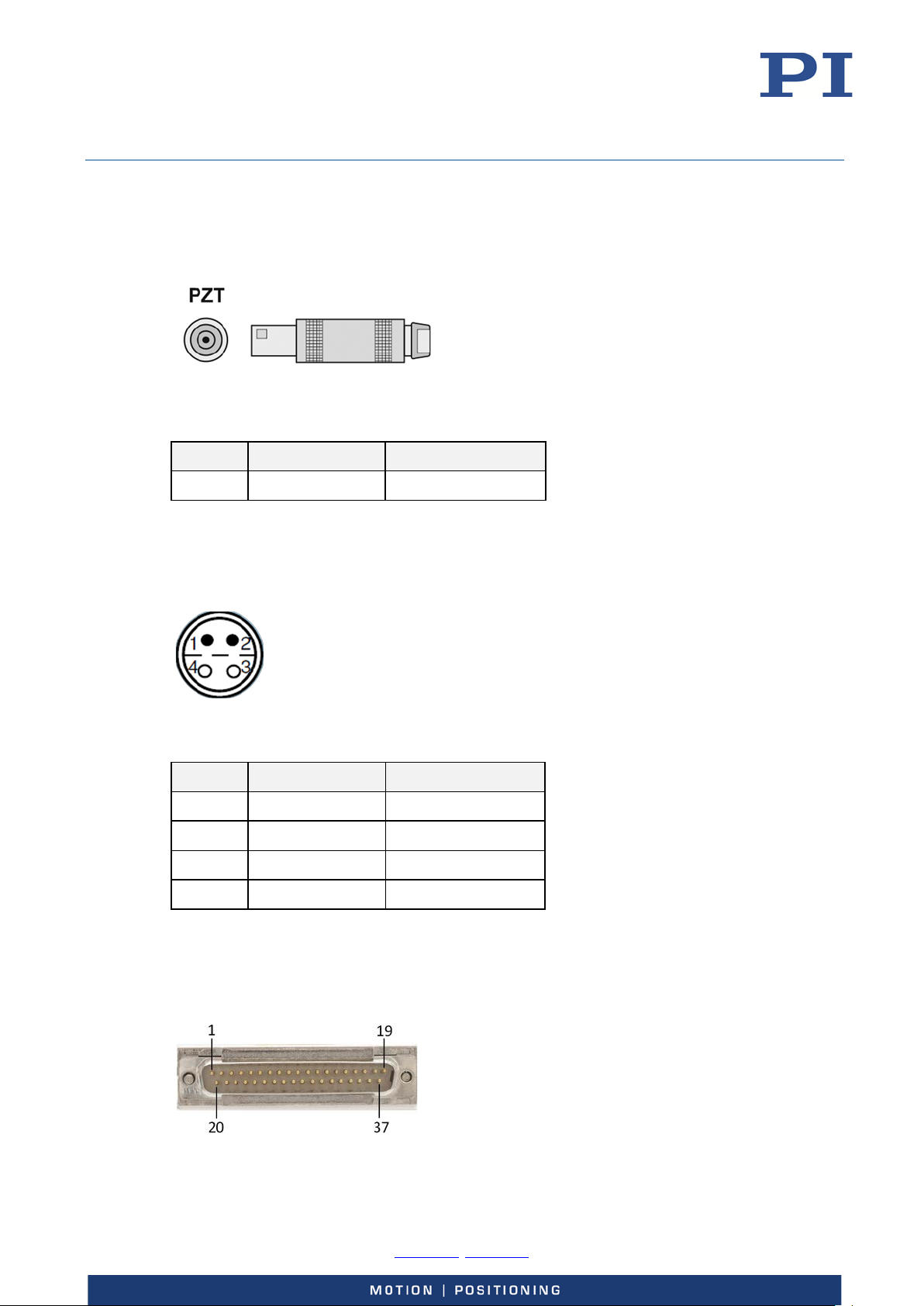
Voltage Connection of S-31x.10
Figure 13: Piezo connector
Signal Function Connector Shell
PZT Piezo Voltage Ground
Sensor Connection of S-316.10
Figure 14: Sensor connection: LEMO connector FFA.0S.304.CLAC32Y, contact side
Pin Signal Function
1 SGS Ref SGS reference
2 SGS- SGS signal (negative)
3 SGS+ SGS signal (positive)
4 SGS GND Ground SGS signal
Voltage and Sensor Connection of S-316.10H
Figure 15: Voltage and sensor connection, sub-D 37 (m)
-0, Fax +49 721 4846-1019, Email [email protected], www.pi.ws
Page 35

User Manual
Physik Instrumente (PI) GmbH & Co. KG, Auf der Roemerstrasse 1, 76228 Karlsruhe, Germany Page 35 / 36
Phone +49 721 4846
S310T0001, valid for S-310, S-311, S-314, S-315 and S-316
KSch, 10/15/2019
Pin Signal Function
1 - -
2 GND Ground
3 ID chip CH2 Data, ID chip CH2
4 - -
5 ID chip GND Ground, ID chip
6 - -
7 GND Ground
8 - -
9 GND Ground
10 SGS CH2+ SGS signal CH2+ (positive)
11 GND Ground
12 SGS CH1+ SGS signal CH1+ (positive)
13 GND -
14 Reserved Reserved
15 Reserved Reserved
16 Piezo CH1+ Piezo voltage, CH1+ (positive)
17 Piezo CH2+ Piezo voltage, CH2+ (positive)
18 Piezo CH3+ Piezo voltage, CH3+ (positive)
19 - -
20 - -
21 ID chip CH1 Data, ID chip CH1
22 ID chip GND Ground, ID chip
23 to 27 - -
28 SGS CH2- SGS signal CH2- (negative)
29 SGS CH2 Ref SGS reference CH2
30 SGS CH1- SGS signal CH1- (negative)
31 SGS CH1 Ref SGS reference CH1
32 Reserved Reserved
33 Reserved Reserved
34 Piezo CH1- Piezo voltage, CH1- (negative)
35 Piezo CH2- Piezo voltage, CH2- (negative)
36 Piezo CH3- Piezo voltage, CH3- (negative)
37 - -
-0, Fax +49 721 4846-1019, Email [email protected], www.pi.ws
Page 36

User Manual
Physik Instrumente (PI) GmbH & Co. KG, Auf der Roemerstrasse 1, 76228 Karlsruhe, Germany Page 36 / 36
Phone +49 721 4846
S310T0001, valid for S-310, S-311, S-314, S-315 and S-316
KSch, 10/15/2019
Old Equipment Disposal
In accordance with the applicable EU law, electrical and electronic equipment may not be
disposed of with unsorted municipal wastes in the member states of the EU.
When disposing of your old equipment, observe the international, national and local rules and
regulations.
To meet the manufacturer’s product responsibility with regard to this product, Physik
Instrumente (PI) GmbH & Co. KG ensures environmentally correct disposal of old PI equipment
that was first put into circulation after 13 August 2005, free of charge.
If you have old PI equipment, you can send it postage-free to the following address:
Physik Instrumente (PI) GmbH & Co. KG
Auf der Roemerstr. 1
D-76228 Karlsruhe, Germany
EU Declaration of Conformity
For the S-31x lift and/or tip/tilt platforms, an EU Declaration of Conformity has been issued in
accordance with the following European directives:
Low Voltage Directive
EMC Directive
RoHS Directive
The applied standards certifying the conformity are listed below.
Safety (Low Voltage Directive): EN 61010-1
EMC: EN 61326-1
RoHS: EN 50581
-0, Fax +49 721 4846-1019, Email [email protected], www.pi.ws
 Loading...