

Page 1
PI miCos GmbH, Freiburger Strasse 30, 79427 Eschbach, Germany
MP129E
Q
User Manual
Version: 1.1.2
Date: 16.05.2019
This document describes the following product:
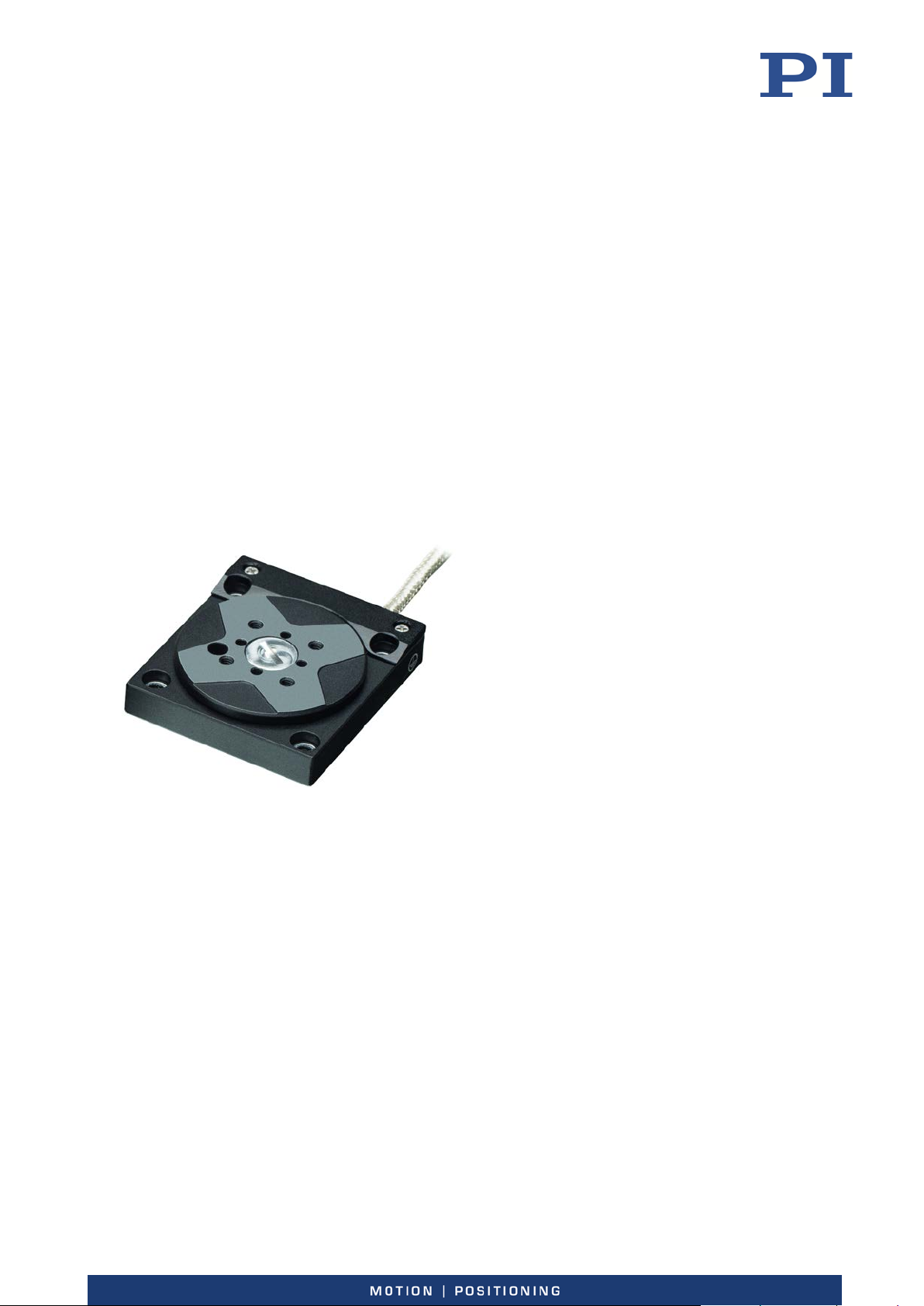
-632 Miniature Rotation Stage
Q-632.930
Q-Motion® rotation stage, piezoelectric inertia
drive, >360° rotation range, incremental
encoder, 0.75 µrad resolution, 6 mNm drive
torque, 30 mm diameter, vacuum compatible
-6
hPa
to 10
Phone +49 7634 5057-0, Fax +49 7634 5057-99, Email [email protected], www.pi.ws
Page 2

The following company names and brands are registered trademarks of Physik Instrumente (PI) GmbH & Co.
KG:
PI®, NanoCube®, PICMA®, PILine®, NEXLINE®, PiezoWalk®, NEXACT®, Picoactuator®, PInano®, PIMag®,
Q-Motion®
The patents held by PI are found in our patent list: http://www.physikinstrumente.com/en/about-pi/patents
© 2019 Physik Instrumente (PI) GmbH & Co. KG, Karlsruhe, Germany. The text, photographs and drawings in
this manual are protected by copyright. With regard thereto, Physik Instrumente (PI) GmbH & Co. KG retains
all the rights. Use of said text, photographs and drawings is permitted only in part and only upon citation of
the source.
Original instructions
First printing: 16.05.2019
Document number: MP129E, KSch, version 1.1.2
Subject to change without notice. This manual is superseded by any new release. The latest release is
available for download (p. 3) on our website.
Page 3

Contents
1 About this Document 1
1.1 Objective and Target Audience of this User Manual.................................................. 1
1.2 Symbols and Typographic Conventions...................................................................... 1
1.3 Definition of Terms ..................................................................................................... 2
1.4 Figures ........................................................................................................................ 2
1.5 Other Applicable Documents ..................................................................................... 3
1.6 Downloading Manuals ................................................................................................ 3
2 Safety 5
2.1 Intended Use .............................................................................................................. 5
2.2 General Safety Instructions ........................................................................................ 5
2.3 Organizational Measures ............................................................................................ 6
2.4 Measures for Handling Vacuum-Compatible Products .............................................. 6
3 Product Description 7
3.1 Product View .............................................................................................................. 7
3.2 Product Labeling ......................................................................................................... 8
3.3 Scope of Delivery ........................................................................................................ 9
3.4 Accessories ............................................................................................................... 10
3.5 Suitable Electronics .................................................................................................. 10
3.6 Technical Features .................................................................................................... 11
3.6.1 Linear Encoder (Sensor) ............................................................................... 11
3.6.2 Reference Point Switch ................................................................................ 11
3.6.3 ID Chip.......................................................................................................... 11
4 Unpacking 13
5 Installation 15
5.1 General Notes on Installation ................................................................................... 15
5.2 Mounting the Q-632 onto an Underlying Surface and Connecting it to a
Protective Earth Conductor ...................................................................................... 16
5.3 Fixing the Load to the Q-632 .................................................................................... 19
5.4 Connecting the Q-632 to the Electronics ................................................................. 20
5.4.1 Overview: Connecting for Atmospheric Operation ..................................... 21
5.4.2 Overview: Connecting for Operating in a Vacuum ...................................... 21
5.4.3 Connecting the Q-632 to the Electronics .................................................... 22
Page 4

6 Startup and Operation 25
6.1 General Notes on Startup and Operation ................................................................ 25
6.2 Starting and Operating the Q-632 ............................................................................ 28
7 Maintenance 31
7.1 General Notes on Maintenance ............................................................................... 31
7.2 Performing a Maintenance Run ............................................................................... 31
7.3 Cleaning the Q-632 ................................................................................................... 31
8 Troubleshooting 33
9 Customer Service 35
10 Technical Data 37
10.1 Specifications ............................................................................................................ 37
10.1.1 Data Table .................................................................................................... 37
10.1.2 Maximum Ratings ........................................................................................ 38
10.1.3 Ambient Conditions and Classifications ...................................................... 39
10.2 Operating Time ......................................................................................................... 39
10.3 Dimensions ............................................................................................................... 40
10.3.1 Q-101.AP1 Adapter Plate ............................................................................. 41
10.3.2 C-815.VF Vacuum Feedthrough for 10
-6
hPa ............................................... 42
10.4 Pin Assignment ......................................................................................................... 44
10.4.1 Q-632.930 (Vacuum Compatible to 10
-6
hPa) .............................................. 44
10.4.2 C-815.VF Vacuum Feedthrough ................................................................... 45
11 Old Equipment Disposal 47
12 EU Declaration of Conformity 49
Page 5
1 About this Document
Downloading Manuals ................................................................................................................... 3
1
About this Document
In this Chapter
Objective and Target Audience of this User Manual ..................................................................... 1
Symbols and Typographic Conventions ......................................................................................... 1
Definition of Terms ........................................................................................................................ 2
Figures ............................................................................................................................................ 2
Other Applicable Documents ......................................................................................................... 3
1.1 Objective and Target Audience of this User Manual
This manual contains information necessary for the intended use of the Q-632.
It assumes that the reader has a fundamental understanding of basic servo systems as well as
motion control concepts and applicable safety procedures.
The latest versions of the user manuals are available for download (p. 3) on our website.
1.2 Symbols and Typographic Conventions
The following symbols and typographic conventions are used in this user manual:
NOTICE
CAUTION
Dangerous situation
Failure to comply could lead to minor injuries or damage to equipment.
Precautionary measures for avoiding the risk.
Dangerous situation
Failure to comply could cause damage to equipment.
Precautionary measures for avoiding.
Q-632 Miniature Rotation Stage MP129E Version: 1.1.2 1
INFORMATION
Information for easier handling, tricks, tips, etc.
Page 6
1 About this Document
Symbol/
Label
1.
2.
Action consisting of one or several steps whose
p. 5 Cross-reference to page 5
RS-232 Labeling of an operating element on the product
1.3 Definition of Terms
Term Explanation
Load capacity Maximum load capacity in the vertical direction when the rotation
stage is mounted horizontally. The contact point of the load is in the
center of the motion platform.
Meaning
Action consisting of several steps whose
sequential order must be observed
sequential order is irrelevant
List item
(example: socket of the RS-232 interface)
Warning sign affixed to the product that refers to
detailed information in this manual.
1.4 Figures
For better understandability, the colors, proportions, and degree of detail in illustrations can
deviate from the actual circumstances. Photographic illustrations may also differ and must not
be seen as guaranteed properties.
2 Version: 1.1.2 MP129E Q-632 Miniature Rotation Stage
Page 7

1 About this Document
1.5 Other Applicable Documents
The devices and software tools from PI mentioned in this documentation are described in their
own manuals.
Description Document
E-873.1AT Q-Motion® controller, 1 channel,
USB interface
E-873.3QTU Q-Motion® controller for
piezoelectric inertia drives, 3 axes, benchtop
device (industry), TCP/IP, USB, I/O, joystick
E-873.10C885 Q-Motion® controller module
for PIMotionMaster, 1 axis, for systems with
piezoelectric inertia drive
PIMikroMove SM148E Software Manual
1.6 Downloading Manuals
INFORMATION
If a manual is missing or problems occur with downloading:
Contact our customer service department (p. 35).
INFORMATION
PZ274E User Manual
PZ273E User Manual
E873T0002 Technical Note
For products that are supplied with software (CD in the scope of delivery), access to the
manuals is protected by a password. Protected content is only displayed on the website after
entering the access data.
You need the product CD to get the access data.
For products with CD: Get access data
1. Insert the product CD into the PC drive.
2. Switch to the Manuals directory on the CD.
3. In the Manuals directory, open the Release News (file including releasenews in the file
name).
4. Get the access data for downloading protected content in the "User login for software
download" section of the Release News. Possible methods for getting the access data:
− Link to a page for registering and requesting the access data
− User name and password is specified
5. If the access data needs to be requested via a registration page:
a) Follow the link in the Release News.
Q-632 Miniature Rotation Stage MP129E Version: 1.1.2 3
Page 8

1 About this Document
b) Enter the required information in the browser window.
c) Click Show login data in the browser window.
d) Note the user name and password shown in the browser window.
Downloading manuals
If you have requested access data for protected contents via a registration page (see above):
Click the links in the browser window to change to the content for your product and log
in using the access data that you received.
General procedure:
1. Open the website www.pi.ws.
2. If access to the manuals is protected by a password:
a) Click Login.
b) Log in with the user name and password.
3. Click Search.
4. Enter the product number up to the period (e.g., P-882) or the product family (e.g.,
PICMA® Bender) into the search field.
5. Click Start search or press the Enter key.
6. Open the corresponding product detail page in the list of search results:
a) If necessary: Scroll down the list.
b) If necessary: Click Load more results at the bottom of the list.
c) Click the corresponding product in the list.
7. Click the Downloads tab.
The manuals are shown under Documentation.
8. Click the desired manual and save it to the hard disk of your PC or to a data storage
medium.
4 Version: 1.1.2 MP129E Q-632 Miniature Rotation Stage
Page 9

2 Safety
Measures for Handling Vacuum-Compatible Products ................................................................. 6
2
Safety
In this Chapter
Intended Use .................................................................................................................................. 5
General Safety Instructions............................................................................................................ 5
Organizational Measures ............................................................................................................... 6
2.1 Intended Use
The Q-632 is a laboratory device as defined by DIN EN 61010-1. It is intended for indoor use and
use in an environment that is free of dirt, oil, and lubricants.
In accordance with its design, the Q-632 is intended for positioning, adjusting and rotating loads
in a rotational axis at different velocities in interval operation. The Q-632 uses a piezoelectric
inertia drive. The drive is self-locking at rest, requires no current, generates no heat, and
maintains its position.
The Q-632 can be mounted in any orientation. The specifications of the Q-632 apply to
horizontal mounting (p. 37).
The Q-632 is not intended for applications in areas where failure would be a considerable risk
for people or the environment. The Q-632 is not intended for continuous operation. For further
information on the operating conditions of the Q-632, see "Technical Data" (p. 37).
The Q-632 has a linear encoder for direct position detection and is designed for an ambient
pressure to 10
-6
hPa.
It is only possible to use the Q-632 as intended when it is completely mounted and connected.
The Q-632 must be operated with suitable electronics (p. 10). The electronics are not in the
scope of delivery of the Q-632.
2.2 General Safety Instructions
The Q-632 is built according to state-of-the-art technology and recognized safety standards.
Improper use can result in personal injury and/or damage to the Q-632.
Use the Q-632 for its intended purpose only, and only when it is in perfect technical
condition.
Read the user manual.
Eliminate any faults and malfunctions likely to affect safety immediately.
The operator is responsible for the correct installation and operation of the Q-632.
Q-632 Miniature Rotation Stage MP129E Version: 1.1.2 5
Page 10

2 Safety
2.3 Organizational Measures
User manual
Always keep this user manual available with the Q-632.
The latest versions of the user manuals are available for download (p. 3) on our
website.
Add all information from the manufacturer to the user manual, for example
supplements or technical notes.
If you give the Q-632 to other users, also include this user manual as well as other
relevant information provided by the manufacturer.
Use the device only if the user manual is complete. Missing information due to an
incomplete user manual can result in minor injury and damage to equipment.
Install and operate the Q-632 only after you have read and understood this user
manual.
Personnel qualification
The Q-632 may only be installed, started, operated, maintained, and cleaned by authorized and
appropriately qualified personnel.
2.4 Measures for Handling Vacuum-Compatible Products
Attention must be paid to appropriate cleanliness when the rotation stage is to be used in a
vacuum. All parts are cleaned at PI before assembly. Powder-free gloves are worn during
assembly and measuring.
Touch the rotation stage only with powder-free gloves.
If necessary, wipe the rotation stage clean after unpacking.
6 Version: 1.1.2 MP129E Q-632 Miniature Rotation Stage
Page 11
3 Product Description
Technical Features ....................................................................................................................... 11
3
Product Description
In this Chapter
Product View .................................................................................................................................. 7
Product Labeling ............................................................................................................................ 8
Scope of Delivery ........................................................................................................................... 9
Accessories ................................................................................................................................... 10
Suitable Electronics ...................................................................................................................... 10
3.1 Product View
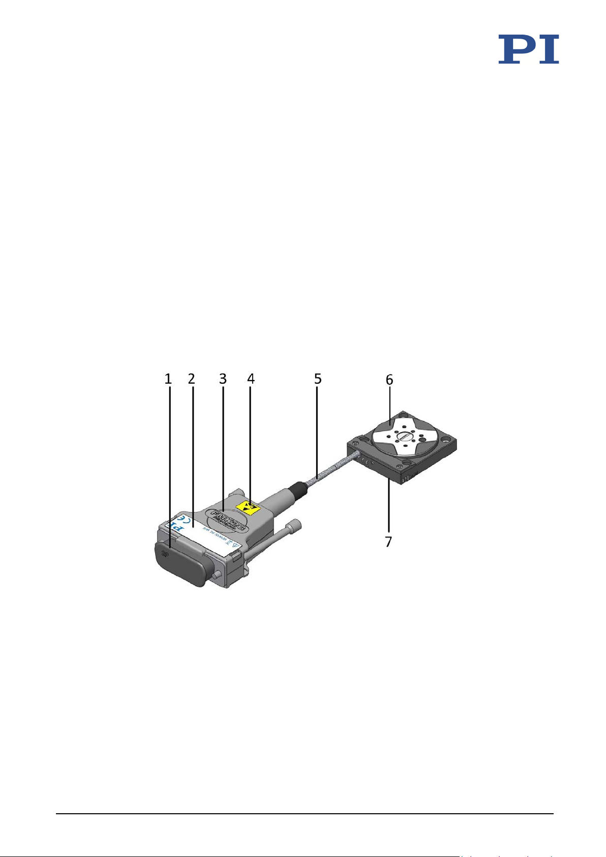
Figure 1: Q-632.930 rotation stage
1 ESD protection cap
2 Type plate p. 8
3 Connector for drive and sensor: D-sub 15 (m)
4 Warning sign "Electrostatic sensitive devices"
5 Cable exit for connecting the drive and sensor
6 Motion platform
7 Base body
Q-632 Miniature Rotation Stage MP129E Version: 1.1.2 7
Page 12
3 Product Description
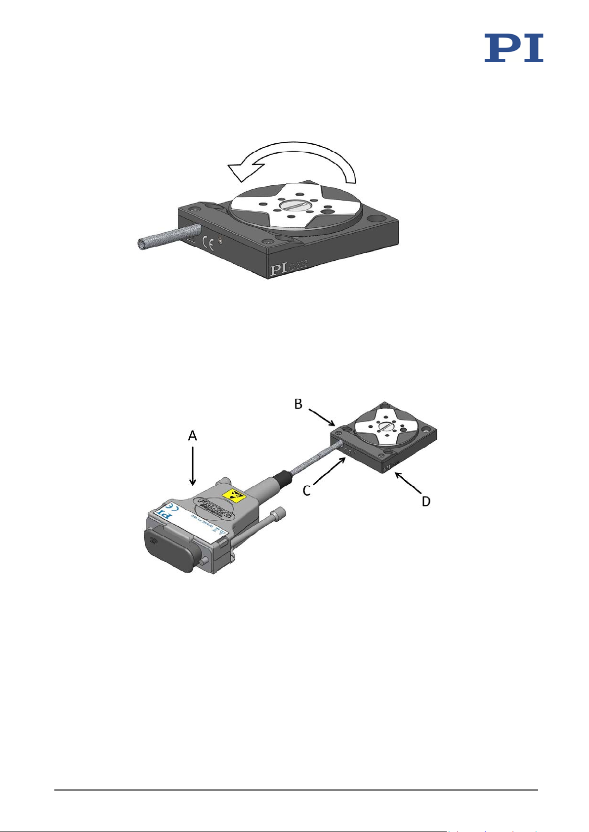
Figure 2: Direction of motion of the Q-632's platform
The arrow in the figure above shows the direction of motion on positive commanding.
3.2 Product Labeling
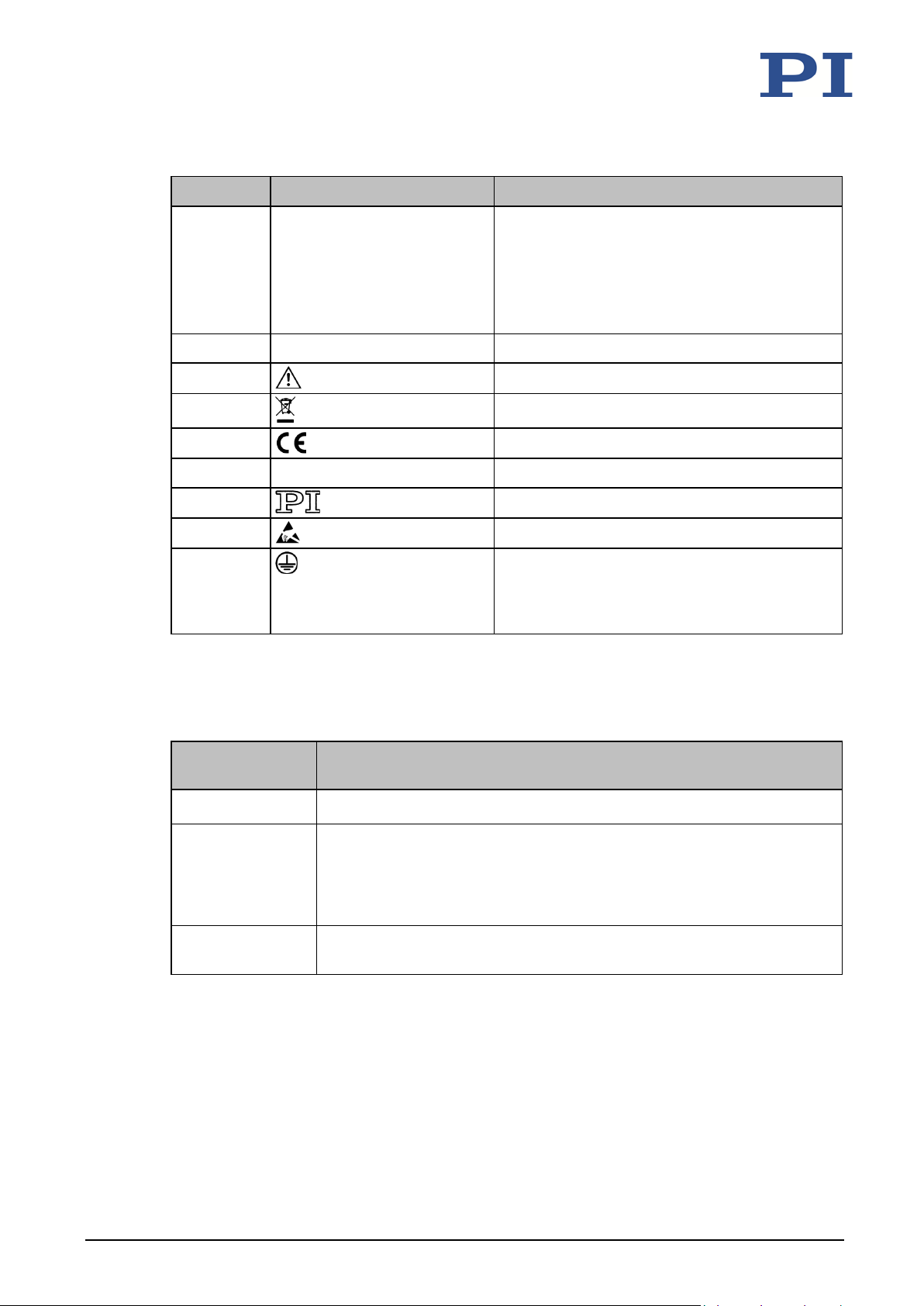
Figure 3: Product labeling and type plate of the rotation stage
8 Version: 1.1.2 MP129E Q-632 Miniature Rotation Stage
Page 13
3 Product Description
632 is to be connected to the protective earth
Position Labeling Description
A 113064246 Serial number (example), individual for each
Q-632
Meaning of each position (from the left):
1 = internal information,
2 and 3 = year of manufacture,
4 to 9 = consecutive number
A Q-632.930 Product name
A, C
A
A, C
A WWW.PIMICOS.COM Manufacturer's address (website)
A, D
A
B
3.3 Scope of Delivery
Item
ID
Q-632 Rotation stage according to the order
Components
Warning sign "Pay attention to the manual!"
Old equipment disposal
CE conformity mark
Manufacturer's logo
Warning sign "Electrostatic-sensitive devices"
Symbol for the protective earth conductor,
marks the position of the holes via which the
Qconductor
RPS32.5003
MP139EK Short instructions for the Q-5xx / Q-6xx Q-Motion® positioners
Q-632 Miniature Rotation Stage MP129E Version: 1.1.2 9
Screw set for mounting the Q-632, consisting of:
2 dowel pins, A2 1.5 m6 × 4 ISO 2338
4 machine screws 1.4567 M2x4 (not required)
4 socket-head screws, A2 M2×6 ISO 4762
Page 14
3 Product Description
3.4 Accessories
Order
number
E-873.UHV1
E-873.UHV2
E-873.UHV3
Q-101.AP1
C-815.VF
Description
Air-side extension cable from the vacuum feedthrough or Q-632 to the
electronics, D-sub 15 (f) to D-sub 15 (m), 1 m
Air-side extension cable from the vacuum feedthrough or Q-632 to the
electronics, D-sub 15 (f) to D-sub 15 (m), 2 m
Air-side extension cable from the vacuum feedthrough or Q-632 to the
electronics, D-sub 15 (f) to D-sub 15 (m), 3 m
Adapter plate for mounting a Q-632 onto an optical table, for use in a
vacuum to 10
Vacuum feedthrough (drive and sensor signals), D-sub 15 (m/f), including
C815T0003 technical note
To order, contact our customer service department (p. 35).
3.5 Suitable Electronics
-6
hPa. Material: Aluminum alloy, anodized; mass: 8 g
Electronics
Order number Description
E-873.1AT Q-Motion® controller for piezoelectric inertia drives, 1 axis, benchtop
device (industry), SPI, TCP/IP, USB, RS-232, I/O, connector for joystick
E-873.3QTU Q-Motion® controller for piezoelectric inertia drives, 3 axes, benchtop
device (industry), TCP/IP, USB, I/O, joystick
E-873.10C885 Q-Motion® controller module for PIMotionMaster, 1 axis, for systems
with piezoelectric inertia drive
To order, contact our customer service department (p. 35).
10 Version: 1.1.2 MP129E Q-632 Miniature Rotation Stage
Page 15

3 Product Description
3.6 Technical Features
3.6.1 Linear Encoder (Sensor)
The Q-632 is equipped with an optical linear encoder. Refer to the table in the "Specifications"
section (p. 37) for the encoder resolution.
Optical linear encoders measure the actual position directly (direct metrology). Therefore,
errors occurring in the drivetrain such as nonlinearity, backlash or elastic deformation, cannot
3.6.2 Reference Point Switch
influence the measurement of the position.
The Q-632 also has an optical reference switch.
The commands that use the reference signal are described in the user manual for the controller
and/or in the corresponding software manuals.
3.6.3 ID Chip
The Q-632 has an ID chip in the connector.
The following data is stored as parameters on the ID chip:
Information on the rotation stage: Type, serial number, date of manufacturer, hardware
version
Settings for the sensor: Interpolation rate, corrections to hysteresis, phase and offset,
gain values
When switched on or rebooted, controllers from PI read the data from the ID chip.
For more information on ID chip detection, see the manual for the controller.
Q-632 Miniature Rotation Stage MP129E Version: 1.1.2 11
Page 16

Page 17

4 Unpacking
4
Unpacking
NOTICE
Electrostatic hazard
Touching the pins on the D-sub 15 connector can damage the Q-632's electrostatic-sensitive
(also: ESD) components. For this reason, the Q-632 is supplied with ESD protection.
Remove the ESD protection from the connection only when you connect the Q-632 to the
controller.
INFORMATION
Attention must be paid to appropriate cleanliness when the rotation stage is to be used in a
vacuum. All parts are cleaned at PI before assembly. Powder-free gloves are worn during
assembly and measuring.
Touch the rotation stage only with powder-free gloves.
If necessary, wipe the rotation stage clean after unpacking.
1. Unpack the Q-632 with care.
2. If present, do not remove the ESD protection from the connection of the Q-632.
3. Compare the contents with the items listed in the contract and the packing list.
4. Inspect the contents for signs of damage. If there is any sign of damage or missing parts,
contact PI immediately.
5. Keep all packaging materials and the ESD protection in case the product needs to be
returned.
Q-632 Miniature Rotation Stage MP129E Version: 1.1.2 13
Page 18

Page 19

5 Installation
Connecting the Q-632 to the Electronics ..................................................................................... 20
5
Installation
In this Chapter
General Notes on Installation ...................................................................................................... 15
Mounting the Q-632 onto an Underlying Surface and Connecting it to a Protective Earth
Conductor .................................................................................................................................... 16
Fixing the Load to the Q-632 ....................................................................................................... 19
5.1 General Notes on Installation
NOTICE
Heating up of the Q-632 during operation!
The heat produced during operation of the Q-632 can affect your application.
Install the Q-632 so that the application is not impaired by the dissipated heat.
Ensure sufficient ventilation at the place of installation.
Make sure that the complete bottom side of the Q-632 is in contact with the surface on
which the Q-632 is mounted.
NOTICE
Unwanted changes in position when mounted vertically!
The motion platform could move unexpectedly if the load exceeds the rotation stage's drive
torque when the Q-632 is mounted vertically (e.g., due to pulling forces on the cable of the
load). Unwanted changes in the position of the motion platform can damage the drive, the
load or the surroundings.
Take suitable measures to make sure that the load is lower than the drive torque (p. 37)
when the rotation stage is mounted vertically, e.g., the cables connected to the load
should have sufficient strain relief.
NOTICE
Lubricants, dirt, condensation!
Dirt, oil, lubricants and condensation will render the motor/drive inoperable.
Keep the Q-632 free from lubricants.
Keep the Q-632 free from dirt and condensation.
Q-632 Miniature Rotation Stage MP129E Version: 1.1.2 15
Page 20

5 Installation
NOTICE
Damage from unsuitable cables!
Unsuitable cables can damage the electronics.
Use cables provided by PI only for connecting the Q-632 to the electronics.
INFORMATION
The positive direction of motion is a counterclockwise rotation.
INFORMATION
The Q-632 can be mounted on an optical stage with the Q-101.AP1 adapter plate. The adapter
plate is available (p. 9)as an accessory.
5.2 Mounting the Q-632 onto an Underlying Surface and Connecting
it to a Protective Earth Conductor
NOTICE
Protruding screw heads!
Protruding screw heads can damage the Q-632.
Ensure that the screw heads do not protrude from countersunk holes so that they do not
interfere with the motion.
NOTICE
16 Version: 1.1.2 MP129E Q-632 Miniature Rotation Stage
Warping of the Q-632 when mounted on uneven surfaces!
The Q-632 could warp if mounted on an uneven surface. Warping reduces the accuracy.
Mount the Q-632 onto an even surface. The recommended flatness of the surface
is ≤2 µm.
For applications with large temperature changes:
Mount the Q-632 only onto surfaces that have the same or similar thermal expansion
properties as the Q-632.
Page 21
5 Installation
INFORMATION
The contact of the Q-632 with the protective earth conductor is made as follows:
Holes that are used for attaching the Q-632:
− Four countersunk holes with ∅ 2.2 mm / ∅ 4.2 mm in the base body of the Q-632
Suitable conductive screws (p. 9)
Protective earth conductor connected to the surface that the Q-632 is mounted on
The screws are secured against unintentional loosening, e.g., with locking paint or
threadlocker
INFORMATION
Pay attention to the applicable standards for connecting the protective earth conductor.
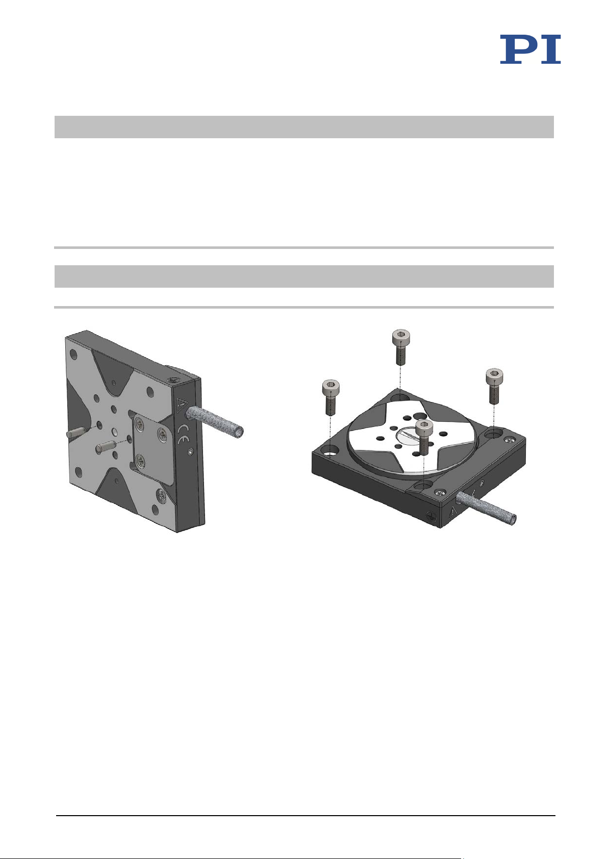
Figure 4: Bottom side of the Q-632: Two of the four
Q-632 Miniature Rotation Stage MP129E Version: 1.1.2 17
available locating holes can be used for
alignment on a surface
Requirements
You have read and understood the general notes on installation (p. 15).
The Q-632 is not connected to the electronics.
You have provided a suitable underlying surface (for the required position and depth of
the holes for accommodating the screws and locating pins, see "Dimensions" (p. 40)):
− The underlying surface must be connected to a protective earth conductor.
− Two locating holes with ∅1.5 mm H7 and four M2 mounting holes are available in
the surface.
− The holes for accommodating the screws have to be sufficiently conductive to
ensure that the protective earth conductor functions properly.
Figure 5: Top of the Q-632: The rotation stage is fixed to
the underlying surface with four screws: 4 socket
head screws (outlying countersunk holes)
Page 22

5 Installation
− For applications with large temperature changes: The surface should have the same
thermal expansion properties as the Q-632 (e.g., underlying surface made of
aluminum).
− The surface flatness is ≤2 µm.
You have accounted for the space required to route cables according to regulations and
without bending them.
Tools and accessories
RPS32.5003 screw set from the scope of delivery of the Q-632 (p. 9):
− 2 dowel pins, 1.5 m6 × 4 ISO 2338; for use as locating pins
− 4 socket head screws, M2×6 ISO 4762
Suitable screwdriver
Mounting the Q-632 onto an underlying surface and connecting it to a protective earth conductor
1. Insert the two locating pins into the locating holes in the bottom of the Q-632 (see
figure above) or in the underlying surface.
2. Put the Q-632 onto the underlying surface so that the locating pins are inserted into the
corresponding locating holes on the other side.
3. Mount the Q-632 on the surface.
a) Insert one M2 socket head screw into one of the four outlying countersunk holes
(Ø 2.2 mm / Ø 4.2 mm) in the base body of the Q-632.
b) Tighten the socket head screw with a maximum torque of 35 Ncm.
c) Make sure that the screw head does not protrude from the countersunk hole.
d) Repeat the steps a) to c) for the other three outlying countersunk holes in the base
body of the Q-632.
4. Make sure that the contact resistance at all connection points relevant for mounting
the protective earth conductor is <0.1 Ω at 25 A.
5. Check that the Q-632 is fixed firmly to the underlying surface.
18 Version: 1.1.2 MP129E Q-632 Miniature Rotation Stage
Page 23
5 Installation
5.3 Fixing the Load to the Q-632
NOTICE
Impermissibly high forces and torques!
Impermissibly high forces and torques that are applied to the motion platform can damage the
Q-632.
For fixing type and mass of the load, pay attention to the maximum permissible forces
according to the specifications (p. 37).
Avoid tilting torques at the motion platform.
NOTICE
Excessively long screws!
The Q-632 can be damaged by excessively long screws.
Note the depth of the mounting holes in the motion platform (p. 40).
Use screws of the correct length for the respective mounting holes only.
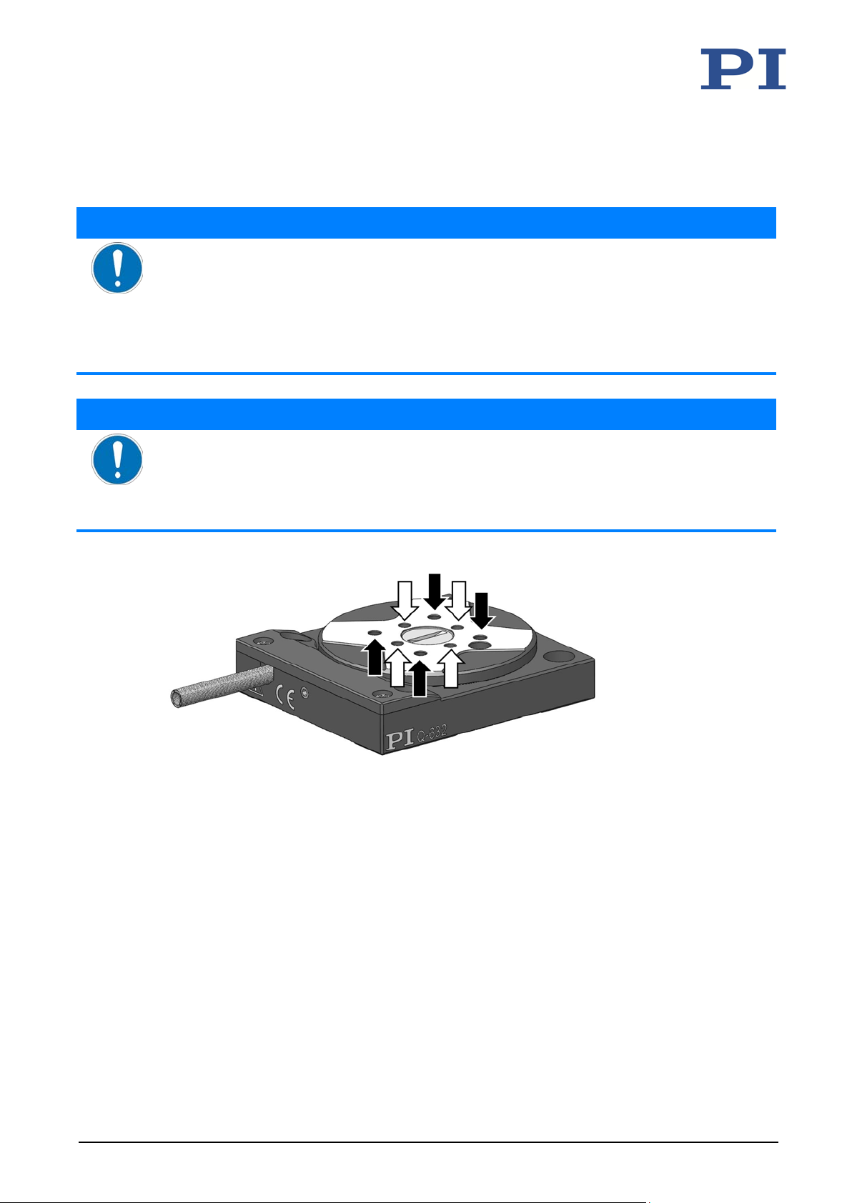
Figure 6: Black arrows indicate locating holes for alignment of the load, whereas white arrows
indicate threaded holes for fixing the load
Requirements
You have read and understood the general notes on installation (p. 15).
You have fixed the Q-632 onto an underlying surface (p. 16) properly.
The Q-632 is not connected to the electronics.
You have prepared the load so that it can be fixed to the motion platform (for the
required position and depth of the holes for accommodating the screws and locating
pins, see "Dimensions" (p. 40)):
Q-632 Miniature Rotation Stage MP129E Version: 1.1.2 19
− The gap between the center of gravity of the load and the center of the motion
platform is as small as possible in all directions.
− Four points are provided for fixing the load to the motion platform.
Page 24

5 Installation
− If you use locating pins for aligning the load: You made two to four locating holes of
Ø 1.5 mm H7 in the load for accommodating locating pins.
Tools and accessories
4 M2 screws of suitable length (p. 40)
Suitable tool for tightening the screws
Optional: 2 to 4 locating pins of suitable length, for locating holes with ∅ 1.5 mm H7
Fixing the load to the Q-632
1. Align the load on the Q-632 so that the mounting holes in the load and the holes in the
motion platform are aligned.
If you use locating pins to align the load:
a) Insert the locating pins into the locating holes in the motion platform or in the load.
b) Place the load on the motion platform so that the locating pins can be inserted into
the corresponding locating holes on the other side.
2. Fix the load using the screws.
− Maximum torque: 35 Ncm.
3. Check that the load is fixed firmly to the motion platform of the Q-632.
5.4 Connecting the Q-632 to the Electronics
INFORMATION
The Q-632 and the electronics can be delivered as a preconfigured system.
If a connection assignment is given on the labels of the Q-632 and/or electronics, pay
attention to this assignment when connecting the Q-632.
20 Version: 1.1.2 MP129E Q-632 Miniature Rotation Stage
Page 25
5 Installation
5.4.1 Overview: Connecting for Atmospheric Operation
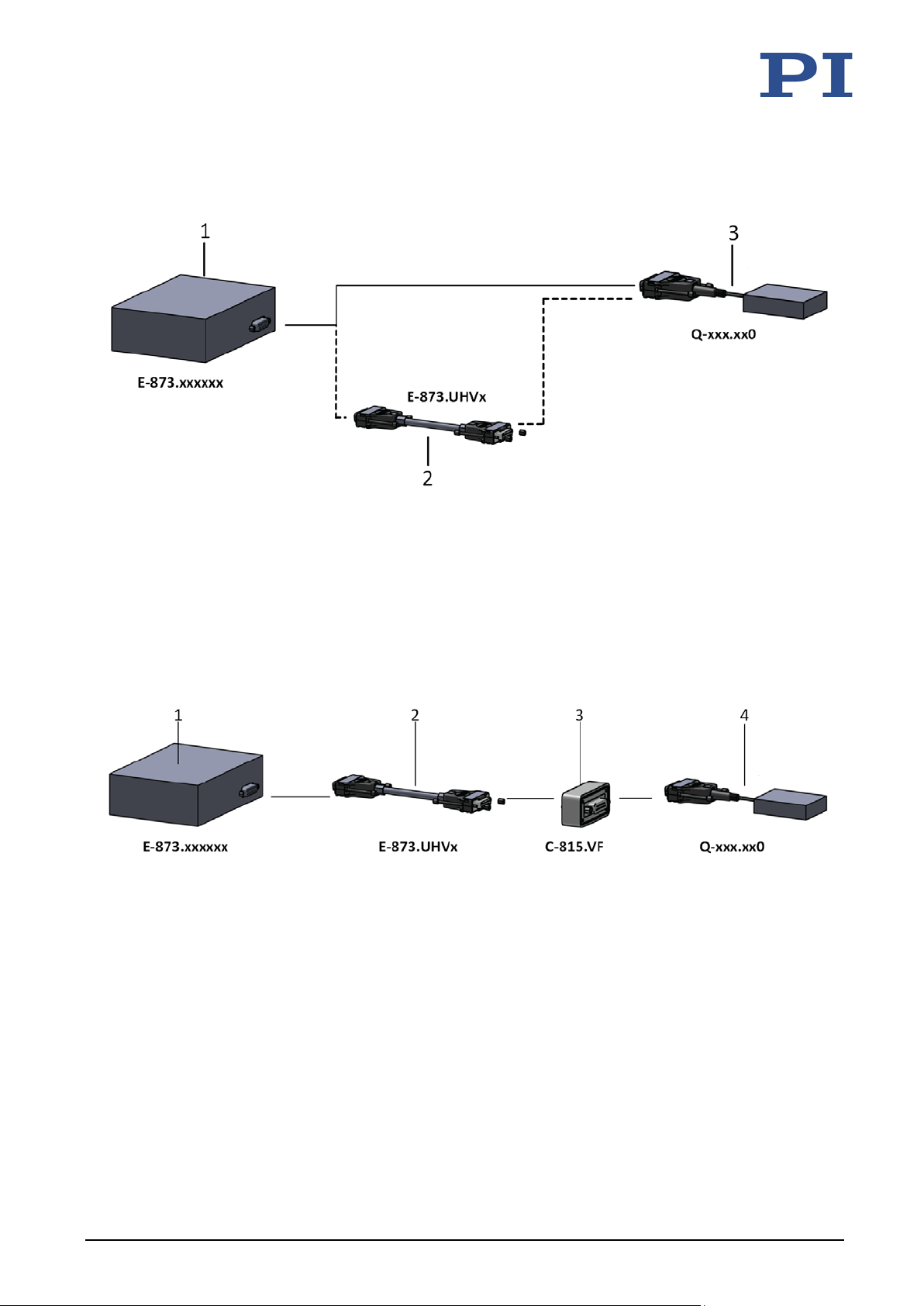
Figure 7: Options for connecting the Q-632 to suitable electronics for atmospheric operation
1 Controller
2 Extension cable
3 Mechanics
5.4.2 Overview: Connecting for Operating in a Vacuum
Figure 8: Connecting the Q-632 to suitable electronics for operating in a vacuum
1 Controller
2 Extension cable
3 Vacuum feedthrough for pressure to 10
4 Mechanics
-6
hPa
Q-632 Miniature Rotation Stage MP129E Version: 1.1.2 21
Page 26
5 Installation
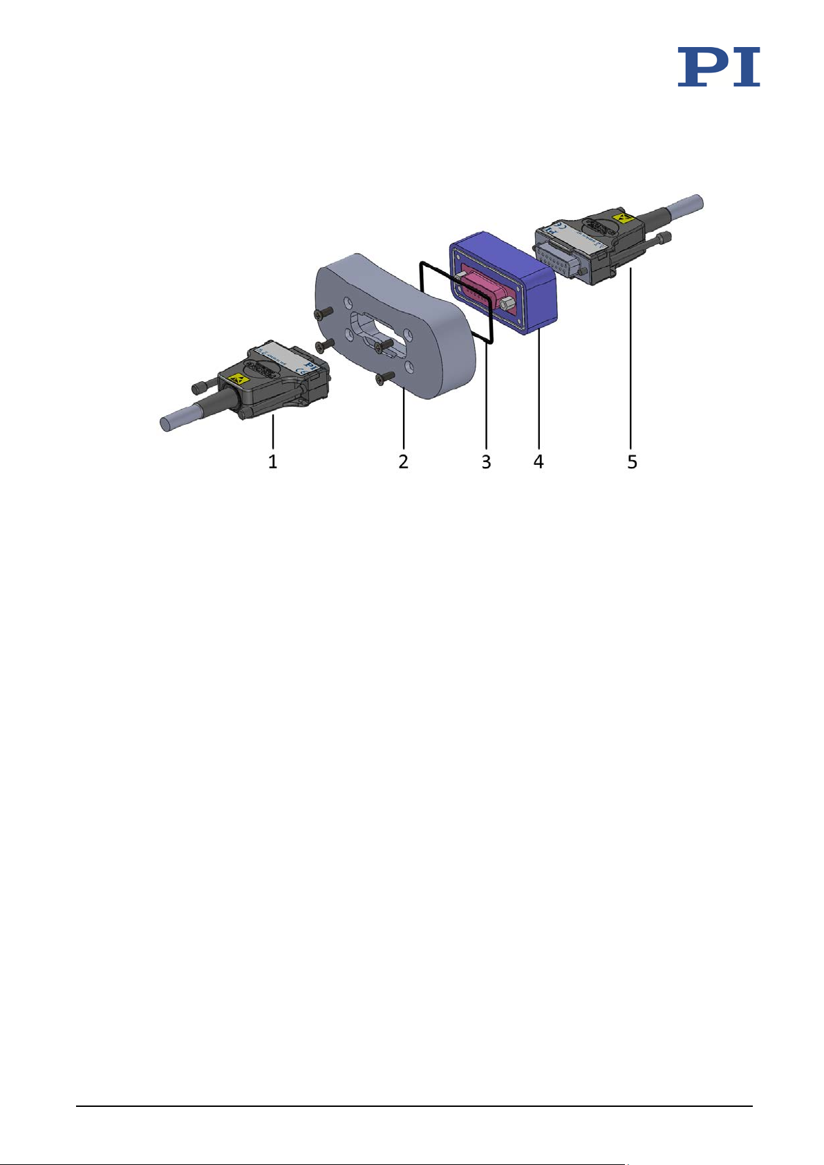
Figure 9: Example for installing the C-815.VF vacuum feedthrough. Left: Vacuum side, right: Air side
1 Q-632's connector on the vacuum side
2 Example of a vacuum feedthrough, part of a vacuum chamber
3 Sealing ring
4 C-815.VF vacuum feedthrough
5 Connector on the air side of the extension cable for connecting to the electronics.
Tools and accessories
Four M3 stainless steel countersunk screws of suitable length (ISO 7046)
Installing the vacuum feedthrough
For C-815.VF vacuum feedthrough: Install the vacuum feedthrough so that the
D-sub 15 (f) socket is in the vacuum chamber.
Pay attention to the maximum torque of 0.9 Nm.
5.4.3 Connecting the Q-632 to the Electronics
22 Version: 1.1.2 MP129E Q-632 Miniature Rotation Stage
Requirements
You have read and understood the general notes on installation (p. 15).
You have installed the electronics.
You have read and understood the user manual for the electronics.
The electronics are not connected to the supply voltage.
Page 27

5 Installation
Tools and accessories
If the Q-632 is to be operated in a vacuum:
− E-873.UHVx extension cable, available as optional accessory (p. 10)
− Suitable vacuum feedthrough, available as an optional accessory (p. 10):
C-815.VF (suitable for use in a vacuum to 10
-6
hPa)
− Suitable tools for installing the vacuum feedthrough
Connecting the Q-632 to the electronics
1. Prepare the Q-632 for connecting:
− Remove the ESD protection from the Q-632's connector.
When a Q-632 is to be operated in a vacuum:
− Installing the vacuum feedthrough:
a) Obtain the dimensions from the corresponding dimensional drawing.
b) Make sure that the vacuum feedthrough is aligned correctly:
C-815.VF: Vacuum side = D-sub 15 (f)
c) Make a suitable opening in the vacuum chamber.
d) Install the vacuum feedthrough.
2. Connect the electronics to the Q-632 and if necessary, any further components as
shown in the connection diagram above.
3. Take suitable measures to prevent the extension cable from being disconnected
accidentally.
Q-632 Miniature Rotation Stage MP129E Version: 1.1.2 23
Page 28

Page 29

6 Startup and Operation
Starting and Operating the Q-632 ............................................................................................... 28
6
Startup and Operation
In this Chapter
General Notes on Startup and Operation .................................................................................... 25
6.1 General Notes on Startup and Operation
CAUTION
Risk of electric shock if the protective earth conductor is not connected!
If a protective earth conductor is not or not properly connected, dangerous touch voltages can
occur on the Q-632 in the case of malfunction or failure of the system. If touch voltages exist,
touching the Q-632 can result in minor injuries from electric shock.
Connect the Q-632 to a protective earth conductor (p. 16) before startup.
Do not remove the protective earth conductor during operation.
If the protective earth conductor has to be removed temporarily (e.g., in the case of
modifications), reconnect the Q-632 to the protective earth conductor before restarting.
CAUTION
Burning from hot surface!
The surface of the Q-632 and its vicinity can heat up during operation. Touching the Q-632 and
surrounding parts can result in minor injuries from burning.
Cool the Q-632 so that the temperature of its surface and surrounding parts does not
exceed 65 °C.
If sufficient cooling is not possible: Make sure that the hot Q-632 and its surrounding parts
cannot be touched.
If sufficient cooling and protection against contact are not possible: Mark the danger zone
in accordance with the legal regulations.
NOTICE
Overheating during continuous operation!
The highest velocity is achieved at maximum operating frequency; however, the Q-632 can
overheat during continuous operation as a result.
Pay attention to the recommended operating time according to the operating frequency in
step mode (p. 39).
Ensure sufficient ventilation at the place of installation.
Q-632 Miniature Rotation Stage MP129E Version: 1.1.2 25
Page 30

6 Startup and Operation
NOTICE
Operating voltage too high or incorrectly connected!
Operating voltages that are too high or incorrectly connected can cause damage to the Q-632.
Operate the Q-632 only with controllers/drivers and original accessories from PI.
Do not exceed the operating voltage range (p. 38) for which the Q-632 is specified.
Operate the Q-632 only when the operating voltage is properly connected; see "Pin
Assignment" (p. 44).
NOTICE
Operating frequency too high!
An excessively high operating frequency can cause damage to the Q-632.
Operate the Q-632 only with controllers/drivers and original accessories from PI.
Do not exceed the operating frequency range (p. 38) specified for the Q-632.
NOTICE
Reduced lifetime of the piezo actuator due to permanently high voltage!
Applying a high static voltage to piezo actuators continuously reduces the lifetime of the piezo
ceramic.
If the Q-632 is not used for a longer period of time, e.g., several days, switch the
electronics off.
NOTICE
Destruction of the piezo actuator due to electric flashovers!
Using the Q-632 in environments that increase the electrical conductivity can lead to the
destruction of the piezo actuator by electric flashovers. Electric flashovers can be caused by
moisture, high humidity, liquids, and conductive materials (e.g., metal dust). In addition,
electric flashovers can also occur in certain air pressure ranges due to the increased
conductivity of the air.
Avoid operating the Q-632 in environments that can increase the electric conductivity.
Operate the Q-632 only within the permissible ambient conditions and classifications
(p. 39).
26 Version: 1.1.2 MP129E Q-632 Miniature Rotation Stage
Page 31

6 Startup and Operation
NOTICE
Damage due to collisions!
Collisions can damage the rotation stage, the load to be moved, and the surroundings.
Make sure that no collisions are possible between the rotation stage, the load to be
moved, and the surroundings in the motion range of the rotation stage.
Do not place any objects in areas where they can be caught by moving parts.
Stop the motion immediately if an electronics malfunction occurs.
NOTICE
Considerable wear due to high operating frequency!
A high operating frequency in step mode can cause considerable wear on the mechanics.
Reduce the operating frequency of the electronics in step mode (step frequency)
respectively the velocity, see the user manual for the electronics.
Reduce the operating time with a high operating frequency (p. 39).
Stop the motion immediately if an electronics malfunction occurs.
NOTICE
Increased wear due to short travel range!
If you only move the Q-632 over a short travel range (<20°), it is necessary to fully rotate
the motion platform once at regular intervals.
INFORMATION
The Q-632's parameters can be adapted. Changing parameter values can cause undesirable
results.
Create a backup copy on the PC before changing the parameter settings; see "Saving
Parameter Values in a Text File" in the user manual for the electronics. You can then
restore the original settings at any time.
You can find information on adapting the parameter values under "Adapting Settings" in
the user manual for the electronics.
Q-632 Miniature Rotation Stage MP129E Version: 1.1.2 27
Page 32

6 Startup and Operation
ay particular attention either to the parameter setting
VEL
6.2 Starting and Operating the Q-632
INFORMATION
If the parameters of the electronics are not adapted to the Q-632 and the application (load,
orientation of the Q-632), the Q-632 will either not move or not move satisfactorily.
Only operate the Q-632 when the parameters of the electronics have been correctly set.
Depending on the electronics used, p
for the operating frequency in step mode or to the velocity in closed-loop operation.
E-873.3QTU:
− Operating frequency in step mode via the parameter with ID 0x1F000400
E-873.1Ax / E-873.10C885
− Velocity via
(closed-loop operation)
INFORMATION
The inertia drive generates noise in step mode. The noise generation depends on the current
step frequency.
INFORMATION
If you use the software from the scope of delivery of the electronics, the operating parameters
can be loaded from PIMicosStages3.dat. The records in the positioner database are updated
regularly.
Install the PI Update Finder from the product CD for the electronics onto your PC and
update PIMicosStages3.dat on your PC.
Further information can be found in the user manual for the electronics.
28 Version: 1.1.2 MP129E Q-632 Miniature Rotation Stage
Requirements
You have read and understood the general notes on startup and operation (p. 25).
You have installed (p. 15) the rotation stage correctly.
You have read and understood the user manual for the electronics.
You have read and understood the manual for the PC software.
The electronics and the required PC software have been installed. All connections to the
electronics have been made (see user manual for the electronics).
Starting and operating the Q-632
1. Start and operate the rotation stage (see user manual for the electronics).
Startup includes the following steps:
− Selecting the positioner type
− Defining the reference point of the axis
− Commanding of first motion for testing
Page 33

6 Startup and Operation
2. If necessary: Adapt the parameters for the operating frequency in step mode or the
velocity (see the user manual for the electronics) to your application (see also "General
Notes on Startup and Operation" (p. 25) and "Operating Time" (p. 39)).
PIMikroMove is used in the user manual for the electronics to describe startup and
operation.
Q-632 Miniature Rotation Stage MP129E Version: 1.1.2 29
Page 34

Page 35

7 Maintenance
Cleaning the Q-632 ...................................................................................................................... 31
7
Maintenance
In this Chapter
General Notes on Maintenance ................................................................................................... 31
Performing a Maintenance Run ................................................................................................... 31
7.1 General Notes on Maintenance
NOTICE
Damage due to improper maintenance!
Improper maintenance can lead to misalignment and failure of the Q-632.
Only loosen screws according to the instructions in this manual.
7.2 Performing a Maintenance Run
The maintenance run must comprise at least one full rotation of the motion platform of the
Q-632.
Do the maintenance run after every 10 million steps.
7.3 Cleaning the Q-632
Requirements
You have disconnected the rotation stage from the electronics.
Cleaning the rotation stage
Only when the rotation stage is not used in vacuum:
When necessary, clean the surfaces of the rotation stage with a cloth that is lightly
dampened with a mild cleanser or disinfectant.
Only when the rotation stage is used in vacuum:
Touch the rotation stage only with powder-free gloves.
If necessary, wipe the rotation stage clean.
Q-632 Miniature Rotation Stage MP129E Version: 1.1.2 31
Page 36

Page 37
8 Troubleshooting
8
Troubleshooting
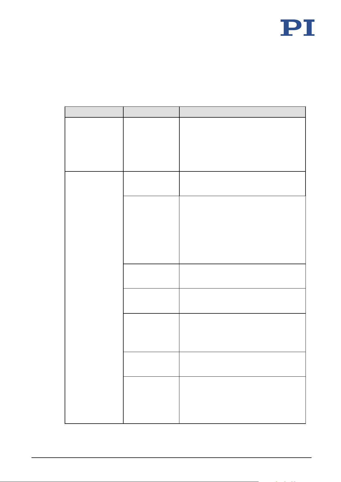
Problem Possible causes Solution
Function impairment
after system
modification
No or limited motion The cable is not
Excessive load Reduce the load. Pay attention to the
The electronics
were replaced
The rotation
stage has been
replaced
connected correctly
or is defective
Parameters of the
electronics
incorrectly set
Load the Q-632's parameter set from the
positioner database.
If necessary: Set the parameters for the
electronics in PIMikroMove so that they
correspond to the application (load,
orientation) of the Q-632 (see user manual
for the electronics).
Check the connecting cable(s)
information in the "Technical Data" section
(p. 37).
Take suitable measures to make sure that
the load exerts a torque that is lower than
the drive torque (p. 37) when the rotation
stage is mounted vertically, e.g., cables
connected to the load should have
sufficient strain relief.
See the "Function impairment after system
modification" problem in this table.
Q-632 Miniature Rotation Stage MP129E Version: 1.1.2 33
Operating voltage
too low
Unfavorable
operating frequency
for step mode
Warped base body Mount the Q-632 on a flat surface. The
Unfavorable load
mounting
Provide an operating voltage of 48 V.
Depending on the electronics used: Adapt
the operating frequency for step mode or
the velocity in closed-loop operation (p. 28)
(For details, see the manual for the
electronics).
recommended flatness of the surface is
2 µm.
Pay attention to the maximum torque when
mounting the load (p. 19).
The gap between the center of gravity of
the load and the center of the motion
platform is as small as possible in all
directions.
Page 38

8 Troubleshooting
Problem Possible causes Solution
Unsuitable ambient
conditions
Drive wear Replace the Q-632 and make sure that the
Drive is blocked Release the blockage carefully by turning
If the problem with your system is not listed in the table above or cannot be solved as
described, contact our customer service department (p. 35).
Operate the Q-632 in a clean environment
only and under permissible ambient
conditions (p. 39).
operating parameters of the electronics are
adapted to the rotation stage.
the motion platform back and forth by
hand.
Contact our customer service department
(p. 35).
34 Version: 1.1.2 MP129E Q-632 Miniature Rotation Stage
Page 39

9 Customer Service
9
Customer Service
For inquiries and orders, contact your PI sales engineer or send us an email ([email protected]).
If you have any questions concerning your system, provide the following information:
− Product and serial numbers of all products in the system
− Firmware version of the controller (if applicable)
− Version of the driver or the software (if applicable)
− Operating system on the PC (if applicable)
If possible: Take photographs or make videos of your system that can be sent to our
customer service department if requested.
The latest versions of the user manuals are available for download (p. 3) on our website.
Q-632 Miniature Rotation Stage MP129E Version: 1.1.2 35
Page 40

Page 41
10 Technical Data
Pin Assignment ............................................................................................................................ 44
10
Technical Data
In this Chapter
Specifications ............................................................................................................................... 37
Operating Time ............................................................................................................................ 39
Dimensions .................................................................................................................................. 40
10.1 Specifications
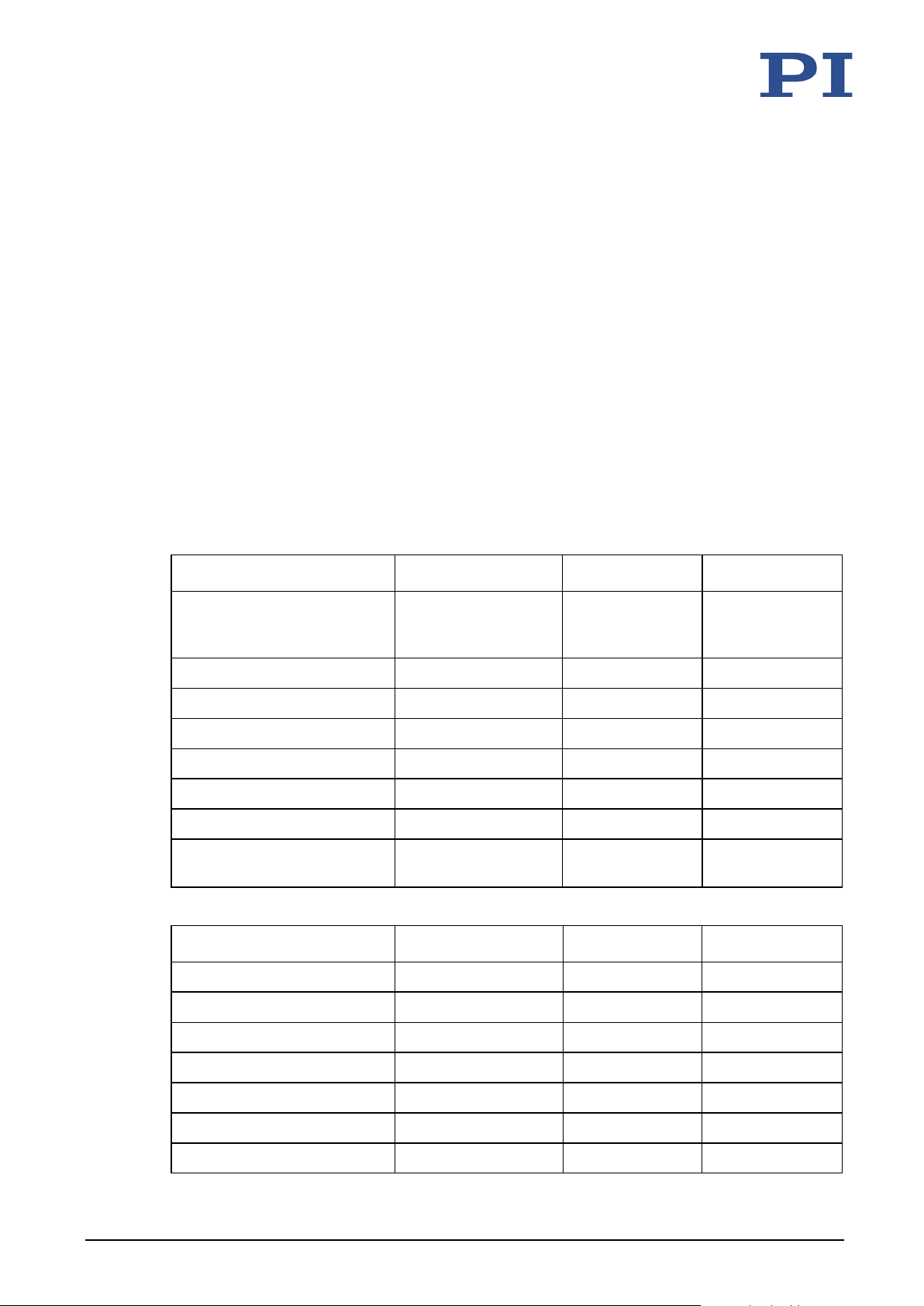
10.1.1 Data Table
Motion and positioning Q-632.930 Unit Tolerance
Rotation stage with
Active axis θ
Rotation range >360 °
Integrated sensor Incremental encoder
Sensor resolution 0.75 µrad
Minimum incremental motion 3 µrad typ.
Unidirectional repeatability 6 µrad typ.
Maximum velocity, closed
loop
Mechanical properties Q-632.930 Unit Tolerance
Load capacity, any orientation 0.1 kg
position sensor for
closed-loop operation
Z
20 °/s
Self-locking 7 mN·m min.
Drive torque 6 mN·m typ.
Length 36 mm
Width 32 mm
Height 8 mm
Turntable diameter 29 mm
Q-632 Miniature Rotation Stage MP129E Version: 1.1.2 37
Page 42
10 Technical Data
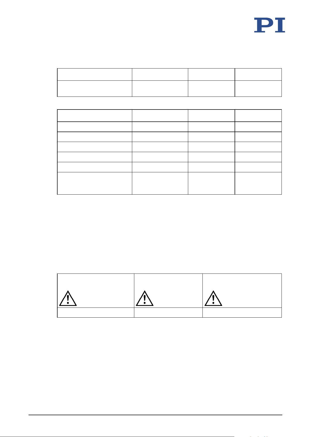
Drive properties Q-632.930 Unit Tolerance
Motor type Piezoelectric inertia
drive
Miscellaneous Q-632.930 Unit Tolerance
Operating temperature range 0 to 40 °C
Material Aluminum, steel
Mass without cable 25 g ±10 %
Cable length 1 m
Connector D-sub 15
Recommended electronics E-873.1AT,
E-873.3QTU,
E-873.10C885
For operation in a vacuum, we recommend a reduced duty cycle of 20% and a reduced rotation
speed of 50% compared to a standard environment.
Specifications tested with E-873.1AT
The specifications were determined on a surface with an evenness of 2 µm.
10.1.2 Maximum Ratings
The Q-632 rotation stage is designed for the following operating data:
Maximum Operating Voltage Maximum Operating
48 V 20 kHz 10 W
Maximum Power Consumption
Frequency
38 Version: 1.1.2 MP129E Q-632 Miniature Rotation Stage
Page 43
10 Technical Data
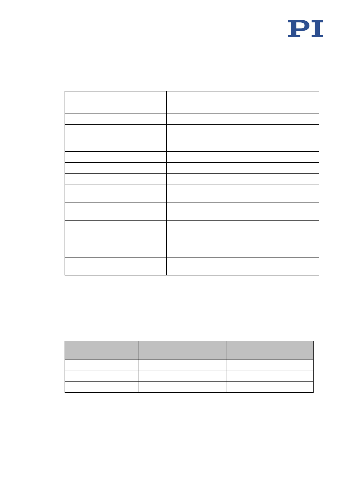
10.1.3 Ambient Conditions and Classifications
Pay attention to the following ambient conditions and classifications for the Q-632:
Area of application For indoor use only
Maximum altitude 2000 m
Air pressure 1100 hPa to 10-6 hPa
Relative humidity Highest relative humidity 80 % for temperatures up
to 31 °C
Decreasing linearly to 50 % relative humidity at 40 °C
Operating temperature 0 °C to 40 °C
Storage temperature -20 °C to 70 °C
Transport temperature -20 °C to 70 °C
Maximum bakeout temperature: 80 °C, for 2 hours, only in switched-off state
Overvoltage category (according to
EN 60664-1 / VDE 0110-1)
Protection class (according to
EN 61140 / VDE 0140 1)
Degree of pollution (according to
EN 60664 1 / VDE 0110 1)
Degree of protection(acc. to
IEC 60529)
10.2 Operating Time
The velocity and the duration of motion affect the lifetime of the rotation stage. In order to
prevent overheating and increased wear, the duration of motion at the specified velocity may
not exceed the values specified in the following table.
Velocity in °/s Maximum duration of motion
20 10 10
15 30 10
in s
1,2
II
I
1
IP20
Idle time in s
Q-632 Miniature Rotation Stage MP129E Version: 1.1.2 39
10 Any 0
1
With the following restraints: Without load, at 20 °C, 48 V supply voltage, and ±0.2 A charging
current
2
It is essential to install effective thermal transfer in order to reach the specified duration of
motion.
Page 44
10 Technical Data
10.3 Dimensions
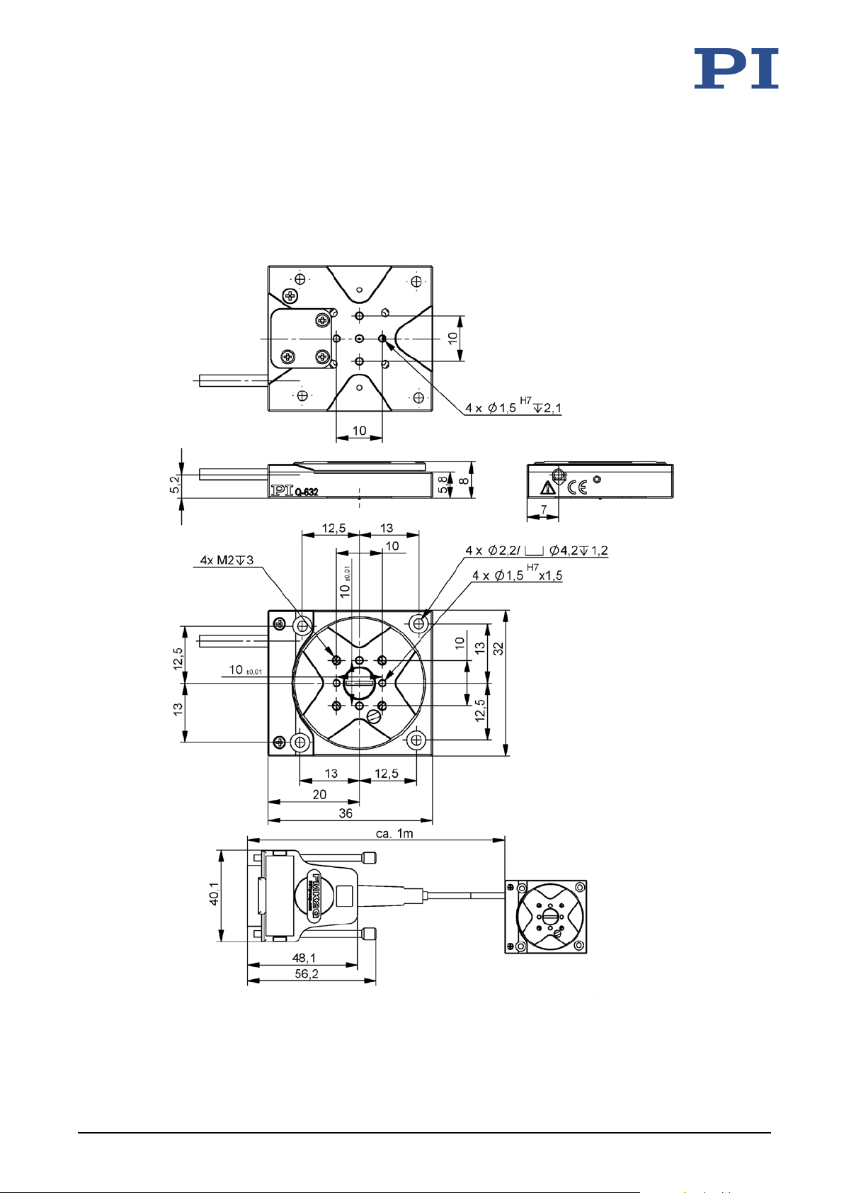
Dimensions in mm. Note that a comma is used instead of a decimal point in the drawings.
40 Version: 1.1.2 MP129E Q-632 Miniature Rotation Stage
Figure 10: Q-632.930
Page 45
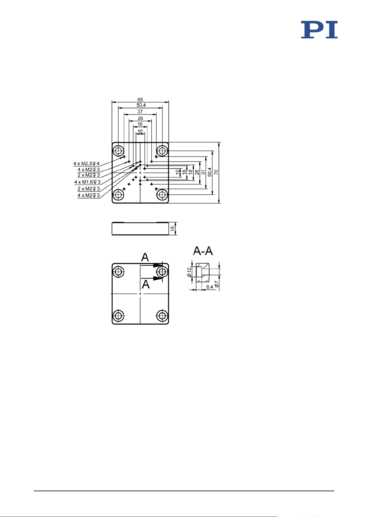
10 Technical Data
10.3.1 Q-101.AP1 Adapter Plate
Dimensions in mm.
Q-632 Miniature Rotation Stage MP129E Version: 1.1.2 41
Figure 11: Q-101.AP1 adapter plate
Page 46
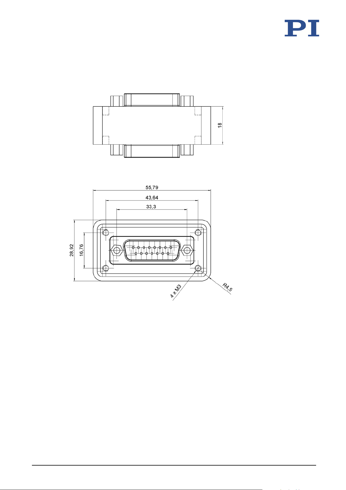
10 Technical Data
10.3.2 C-815.VF Vacuum Feedthrough for 10
Dimensions in mm. Note that a comma is used in the drawings instead of a decimal point.
-6
hPa
42 Version: 1.1.2 MP129E Q-632 Miniature Rotation Stage
Figure 12: C-815.VF vacuum feedthrough D-sub 15 (m/f)
Page 47
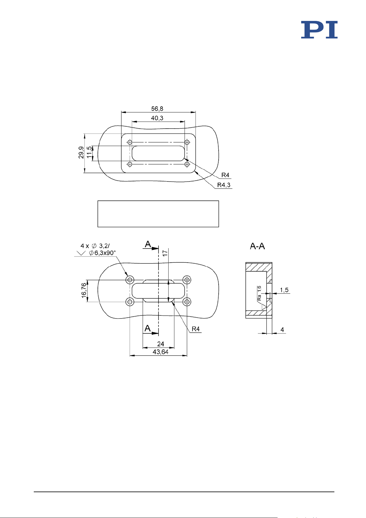
10 Technical Data
Recommended vacuum chamber opening for the C-815.VF vacuum feedthrough for 10-6 hPa
Dimensions in mm. Note that a comma is used in the drawings instead of a decimal point.
Q-632 Miniature Rotation Stage MP129E Version: 1.1.2 43
Figure 13: Top: View of the opening on the air side; middle: Section of the vacuum chamber as
specified by the customer; bottom: View from the vacuum side
Page 48
10 Technical Data
10.4 Pin Assignment
10.4.1 Q-632.930 (Vacuum Compatible to 10
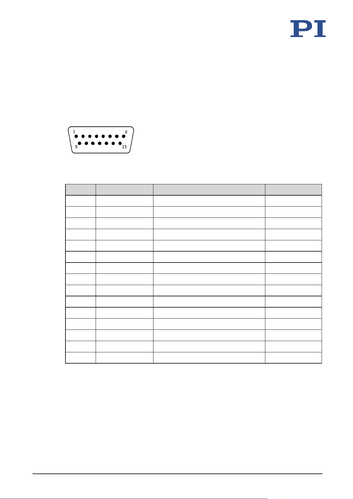
Connector: D-sub 15 (m)
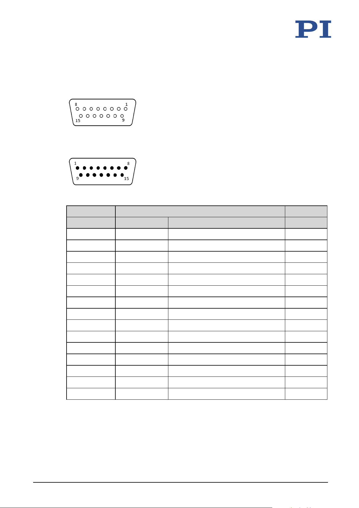
The D-sub 15 connector (m) transmits the signals from the drive, the sensor, and the ID chip.
Figure 14: D-sub 15 (m) connector
Pin Signal* Function Direction
1 REF - Reference signal differential (-) Output
2 Motor (-) Motor signal differential (-) Input
3 Motor (+) Motor signal differential (+) Input
4 VDD Supply voltage (+5 V) Input
5 - - -
6 ID chip data ID chip data Output
-6
hPa)
7 SIN - Encoder A (-) Output
8 COS - Encoder B (-) Output
9 Motor (-) Motor signal differential (-) Input
10 GND GND GND
11 Motor (+) Motor signal differential (+) Input
12 - - -
13 REF + Reference signal differential (+) Output
14 SIN + Encoder A (+) Output
15 COS + Encoder B (+) Output
* The "-" sign indicates that the corresponding pin has not been assigned.
The cable shield is connected to the connector shell.
44 Version: 1.1.2 MP129E Q-632 Miniature Rotation Stage
Page 49
10 Technical Data
10.4.2 C-815.VF Vacuum Feedthrough
D-sub 15 (m/f)
Figure 15: Vacuum side: D-sub 15 (f)
Figure 16: Air side: D-sub 15 (m) panel plug
Vacuum side (f)
Pin Signal Function Pin
1 REF - Reference signal differential (-) 1
2 Motor (-) Motor signal differential (-) 2
3 Motor (+) Motor signal differential (+) 3
4 VDD Supply voltage (+5 V) 4
5 - - 5
6 ID chip data ID chip data 6
7 SIN - Encoder A (-) 7
8 COS - Encoder B (-) 8
9 Motor (-) Motor signal differential (-) 9
10 GND GND 10
11 Motor (+) Motor signal differential (+) 11
12 - - 12
13 REF + Reference signal differential (+) 13
14 SIN + Encoder A (+) 14
Air side (m)
Q-632 Miniature Rotation Stage MP129E Version: 1.1.2 45
15 COS + Encoder B (+) 15
Page 50

Page 51

11 Old Equipment Disposal
11
Old Equipment Disposal
In accordance with EU law, electrical and electronic equipment may not be disposed of in EU
member states via the municipal residual waste.
Dispose of your old equipment according to international, national, and local rules and
regulations.
In order to fulfil the responsibility as the product manufacturer, PI miCos GmbH undertakes
environmentally correct disposal of all old PI miCos equipment made available on the market
after 13 August 2005 without charge.
Any old PI miCos equipment can be sent free of charge to the following address:
PI miCos GmbH
Freiburger Strasse 30
79427 Eschbach, Germany
Q-632 Miniature Rotation Stage MP129E Version: 1.1.2 47
Page 52

Page 53
12 EU Declaration of Conformity
12
EU Declaration of Conformity
For the Q-632, an EU Declaration of Conformity has been issued in accordance with the
following European directives:
Low Voltage Directive
EMC Directive
RoHS Directive
The applied standards certifying the conformity are listed below.
Safety (Low Voltage Directive): EN 61010-1
EMC: EN 61326-1
RoHS: EN 50581
Q-632 Miniature Rotation Stage MP129E Version: 1.1.2 49
 Loading...