

Page 1
PI Ceramic GmbH, Lindenstrasse, 07589 Lederhose, Germany
PZ265E
PL0xx/PDxxx Piezo Actuator
User Manual
Version: 1.0.0
Date: 09.12.2016
This document describes the following products:
PL022 / PL033 / PL055 / PL088
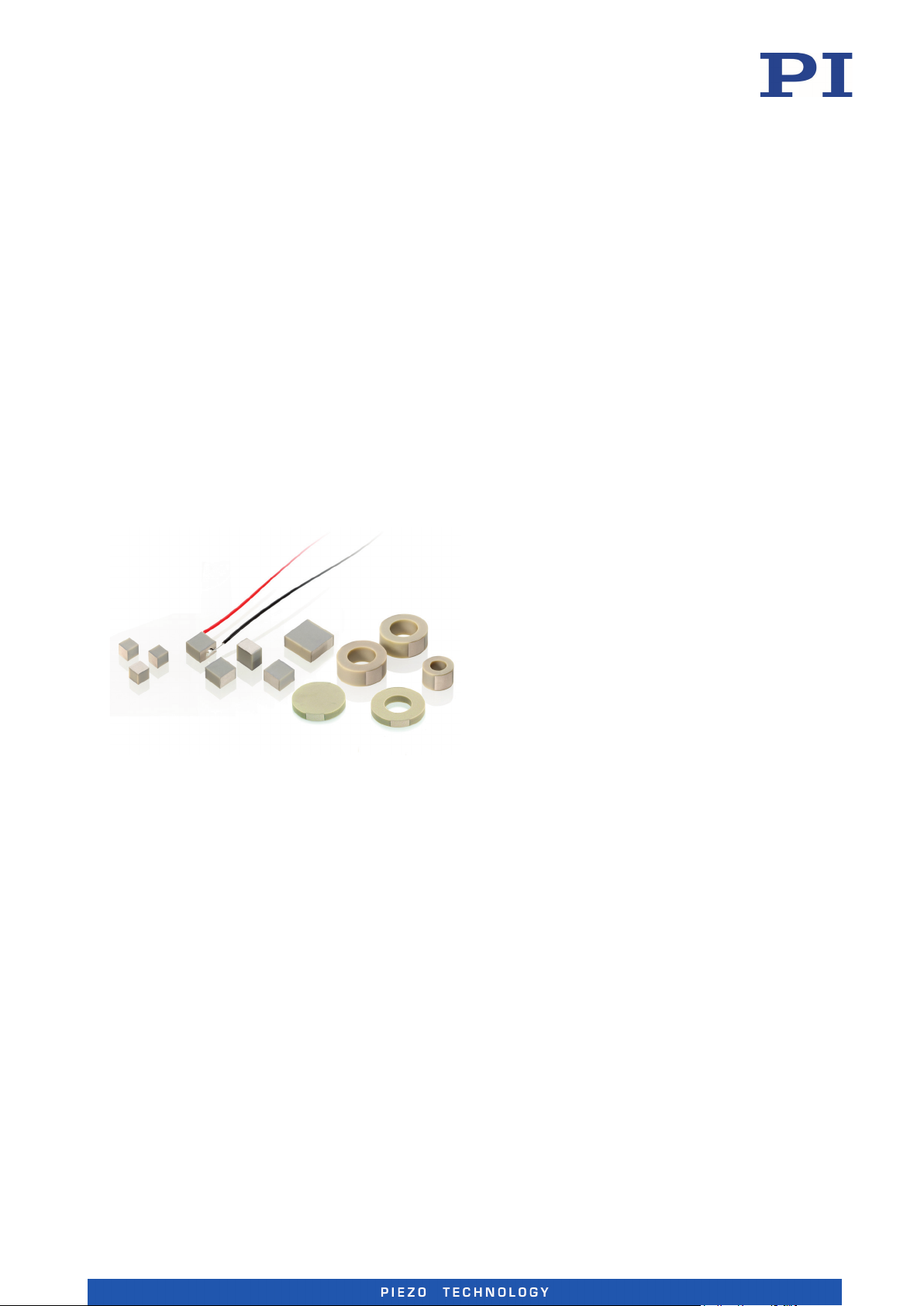
PICMA® Chip miniature multilayer piezo
actuators
PD161
Round PICMA® Chip miniature multilayer piezo
actuators
PD050 / PD080 / PD120 / PD150 / PD160
Round PICMA® Chip miniature multilayer piezo
actuators with inner hole
Phone +49 36604 882-0, Fax +49 36604 882-4109, Email [email protected], www.piceramic.com
Page 2

The following company names and brands are registered trademarks of Physik Instrumente (PI) GmbH & Co.
KG:
PI®, NanoCube®, PICMA®, PILine®, NEXLINE®, PiezoWalk®, NEXACT®, Picoactuator®, PInano®, PIMag®, QMotion®
© 2016 PI Ceramic GmbH, Lederhose, Germany. The text, photographs and drawings in this manual are
protected by copyright. With regard thereto, PI Ceramic GmbH retains all the rights. Use of said text,
photographs and drawings is permitted only in part and only upon citation of the source.
Original instructions
First printing: 09.12.2016
Document number: PZ265E, CBo, Version 1.0.0
Subject to change without notice. This manual is superseded by any new release. The latest release is
available for download (p. 3) on our website.
Page 3

Contents
1 About this Document 1
1.1 Objective and Target Audience of this User Manual.................................................. 1
1.2 Validity for Custom Products ...................................................................................... 1
1.3 Symbols and Typographic Conventions...................................................................... 2
1.4 Figures ........................................................................................................................ 2
1.5 Other Applicable Documents ..................................................................................... 3
1.6 Downloading Manuals ................................................................................................ 3
2 Safety 5
2.1 Intended Use .............................................................................................................. 5
2.2 General Safety Instructions ........................................................................................ 5
2.3 Organizational Measures ............................................................................................ 7
3 Product Description 9
3.1 Model Overview ......................................................................................................... 9
3.2 Product View ............................................................................................................ 10
3.3 Product Labeling ....................................................................................................... 11
3.4 Scope of Delivery ...................................................................................................... 12
3.5 Suitable Electronics .................................................................................................. 12
3.6 Accessories ............................................................................................................... 12
3.7 Technical Features .................................................................................................... 13
4 Unpacking 15
5 Installation 17
5.1 General Notes on Installation ................................................................................... 17
5.2 Connecting a Piezo Actuator with Stranded Wires (Only Models Without
Stranded Wires) ........................................................................................................ 22
5.2.1 Soldering Stranded Wires to a Piezo Actuator (Only Models Without
Stranded Wires) ........................................................................................... 22
5.2.2 Gluing Stranded Wires to a Piezo Actuator (Only Models Without
Stranded Wires) ........................................................................................... 24
5.3 Mounting the PL0xx/PDxxx ...................................................................................... 26
5.4 Applying a Preload .................................................................................................... 27
5.5 Applying the Load ..................................................................................................... 28
5.6 Connecting the PL0xx/PDxxx to the Electronics ....................................................... 29
Page 4

6 Start-Up and Operation 31
6.1 General Notes on Start-Up and Operation ............................................................... 31
6.2 Determining the Operating Parameters ................................................................... 35
6.2.1 Overview of Limiting Factors ....................................................................... 36
6.2.2 Calculating the Effective Mass ..................................................................... 37
6.2.3 Calculating the Maximum Operating Frequency of the Loaded Piezo
Actuator ....................................................................................................... 37
6.2.4 Calculating the Forces that Occur During Dynamic Operation .................... 38
6.2.5 Calculating the Power Requirement for Sinusoidal Operation ................... 39
6.3 Operating the PL0xx/PDxxx ...................................................................................... 39
6.4 Discharging the PL0xx/PDxxx.................................................................................... 40
6.5 Short-Circuiting the PL0xx/PDxxx ............................................................................. 41
7 Maintenance 43
7.1 General Notes on Maintenance ............................................................................... 43
7.2 Cleaning the PL0xx/PDxxx ........................................................................................ 43
8 Troubleshooting 45
9 Customer Service 47
10 Technical Data 49
10.1 Specifications ............................................................................................................ 49
10.1.1 Data Table .................................................................................................... 49
10.1.2 Maximum Ratings ........................................................................................ 51
10.1.3 Compressive/Tensile Stress Capacity and Preload ...................................... 52
10.1.4 Ambient Conditions and Classifications ...................................................... 53
10.2 Dimensions ............................................................................................................... 54
11 Disposal 57
12 EU Declaration of Conformity 59
Page 5

1 About this Document
Downloading Manuals ................................................................................................................... 3
1
About this Document
In this Chapter
Objective and Target Audience of this User Manual ..................................................................... 1
Validity for Custom Products ......................................................................................................... 1
Symbols and Typographic Conventions ......................................................................................... 2
Figures ............................................................................................................................................ 2
Other Applicable Documents ......................................................................................................... 3
1.1 Objective and Target Audience of this User Manual
This user manual contains the necessary information for the intended use of the PL0xx/PDxxx
(x stands for the different models, p. 9).
Basic knowledge of drive technologies and suitable safety measures is assumed.
1.2 Validity for Custom Products
This user manual also applies to custom products from the following product lines if nothing
else is stated in their accompanying documentation:
PICMA® Chip actuators
Round PICMA® Chip actuators
The product line is stated on the delivery note of the custom product.
The properties of custom products may differ from those stated in this manual.
The latest versions of the user manuals are available for download (p. 3) on our website.
PL0xx/PDxxx Piezo Actuator PZ265E Version: 1.0.0 1
Page 6
1 About this Document
1.3 Symbols and Typographic Conventions
The following symbols and typographic conventions are used in this user manual:
CAUTION
Dangerous situation
If not avoided, the dangerous situation will result in minor injuries or damage to the
equipment.
Actions to take to avoid the situation.
NOTICE
Dangerous situation
If not avoided, the dangerous situation will result in damage to the equipment.
Actions to take to avoid the situation.
INFORMATION
Information for easier handling, tricks, tips, etc.
Symbol Meaning
1.
2.
Action consisting of several steps whose sequential order must be observed
p. 5 Cross-reference to page 5
RS-232 Labeling of an operating element on the product (example: socket of the
1.4 Figures
For better understandability, the colors, proportions, and degree of detail in illustrations can
deviate from the actual circumstances. Photographic illustrations may also differ and must not
be seen as guaranteed properties.
Action consisting of one or several steps whose sequential order is irrelevant
List item
RS-232 interface)
2 Version: 1.0.0 PZ265E PL0xx/PDxxx Piezo Actuator
Page 7

1 About this Document
manuals is protected by a password. Protected manuals are only displayed on the website after
1.5 Other Applicable Documents
The devices and software tools that are mentioned in this documentation are described in their
own manuals.
Product Document
E-503 piezo amplifier module PZ62E user manual
E-504 piezo amplifier module PZ62E user manual
E-505 piezo amplifier module PZ62E user manual
E-506 piezo charge amplifier PZ62E user manual
E-610 piezo amplifier / servo controller PZ72E user manual
PZ70E user manual
E-617 high-performance piezo amplifier PZ201E user manual
The latest versions of the user manuals are available for download (p. 3) on our website.
E-618 high-performance piezo amplifier /
PZ221E user manual
servo controller
E-663 piezo amplifier PZ69E user manual
E-831 piezo amplifier module PZ191E user manual
PZ235E user manual
E-836 compact piezo amplifier / OEM module PZ250E user manual
1.6 Downloading Manuals
INFORMATION
If a manual is missing or problems occur with downloading:
Contact our customer service department (p. 47).
INFORMATION
For products that are supplied with software (CD in the scope of delivery), access to the
entering the password.
The password is included on the CD of the product.
PL0xx/PDxxx Piezo Actuator PZ265E Version: 1.0.0 3
Page 8

1 About this Document
For products with CD: Identify the password
1. Insert the product CD into the PC drive.
2. Switch to the Manuals directory on the CD.
3. In the Manuals directory, open the Release News (file including releasenews in the file
name).
4. Find the user name and the password in the section "User login for software download"
in the Release News.
Downloading manuals
1. Open the website www.pi.ws.
2. If access to the manuals is protected by a password:
a) Click Login.
b) Log in with the user name and password.
3. Click Search.
4. Enter the product number up to the period (e.g., P-882) or the product family (e.g.,
PICMA® Bender) into the search field.
5. Click Start search or press the Enter key.
6. Open the corresponding product detail page in the list of search results:
a) If necessary: Scroll down the list.
b) If necessary: Click Load more results at the end of the list.
c) Click the corresponding product in the list.
7. Scroll down to the Downloads section on the product detail page.
The manuals are displayed under Documentation.
8. Click the desired manual and save it to the hard disk of your PC or to a data storage
medium.
4 Version: 1.0.0 PZ265E PL0xx/PDxxx Piezo Actuator
Page 9

2 Safety
Organizational Measures ............................................................................................................... 7
2
Safety
In this Chapter
Intended Use .................................................................................................................................. 5
General Safety Instructions............................................................................................................ 5
2.1 Intended Use
The PL0xx/PDxxx is intended to be used in an environment which is free of dirt, oil, and
lubricants.
In accordance with its design, the PL0xx/PDxxx is intended for integration into a mechanical
system and for the following applications:
Positioning of loads
Dynamic positioning
Vibration damping
Force generation
The operator is responsible for a standards-compliant integration of the PL0xx/PDxxx into the
overall system.
The motion of the PL0xx/PDxxx takes place on one axis. When mounting the actuator without
applying a preload, observe the maximum tensile stress capacity (p. 52).
For operation of the PL0xx/PDxxx, suitable electronics that provide the required operating
voltages are required. The electronics are not included in the scope of delivery of the
PL0xx/PDxxx. We recommend the use of suitable electronics (p. 12) from PI.
2.2 General Safety Instructions
The PL0xx/PDxxx is built according to state-of-the-art technology and recognized safety
standards. Improper use can result in personal injury and/or damage to the PL0xx/PDxxx.
Only use the PL0xx/PDxxx for its intended purpose, and only use it if it is in a good
working order.
Read the user manual.
Immediately eliminate any faults and malfunctions that are likely to affect safety.
The operator is responsible for the correct installation and operation of the PL0xx/PDxxx.
PL0xx/PDxxx Piezo Actuator PZ265E Version: 1.0.0 5
Page 10

2 Safety
Temperature changes and compressive stresses can induce charges in the PL0xx/PDxxx piezo
actuator. After disconnection from the electronics, the piezo actuator can remain charged for
several hours. Touching the live parts of the PL0xx/PDxxx can result in minor injury from electric
shock.
Do not touch the piezo actuator unless it is discharged (p. 40).
When handling the piezo actuator, wear powder-free nitrile or latex gloves.
Keep the piezo actuator short-circuited (p. 41) when it is not connected to the
electronics.
Do not disassemble the piezo actuator.
The system into which the piezo actuator is integrated (e.g., housing or surrounding mechanical
system) must be connected to a protective earth conductor. If the protective earth conductor is
not or not properly connected, touching the system in which the piezo actuator was
incorporated can lead to minor injury from electric shock in the case of a malfunction.
Before start-up, connect the overall system to a protective earth conductor in
accordance with the applicable standards.
Do not remove the protective earth conductor during operation.
If the protective earth conductor has to be temporarily removed (e.g., for
modifications), reconnect the overall system to the protective earth conductor before
starting it up again.
During operation, the piezo actuator carries voltages of up to 100 V. Touching the piezo
actuator can lead to minor injuries from electric shock.
Do not touch the piezo actuator during operation.
Before start-up, insulate the piezo actuator electrically from the surrounding
mechanical system to prevent direct or indirect contact with live parts. Observe the
clearances and creepage distances required for the operating voltage, and observe the
standards applicable to your application.
Mechanical forces can damage or misalign the PL0xx/PDxxx.
Avoid impacts that affect the PL0xx/PDxxx.
Do not drop the PL0xx/PDxxx.
Prevent torques and lateral forces on the PL0xx/PDxxx.
Do not use metal tools during installation.
Do not exceed the maximum permissible stress and load capacities according to the
specifications (p. 49).
6 Version: 1.0.0 PZ265E PL0xx/PDxxx Piezo Actuator
Page 11

2 Safety
2.3 Organizational Measures
User manual
Always keep this user manual available with the PL0xx/PDxxx.
The latest versions of the user manuals are available for download (p. 3) on our
website.
Add all information from the manufacturer to the user manual, for example
supplements or technical notes.
If you give the PL0xx/PDxxx to other users, also include this user manual as well as
other relevant information provided by the manufacturer.
Only use the device on the basis of the complete user manual. Missing information due
to an incomplete user manual can result in minor injury and damage to equipment.
Only install and operate the PL0xx/PDxxx after you have read and understood this user
manual.
Personnel qualification
The PL0xx/PDxxx may only be installed, started up, operated, maintained, and cleaned by
authorized and appropriately qualified personnel.
PL0xx/PDxxx Piezo Actuator PZ265E Version: 1.0.0 7
Page 12

Page 13
3 Product Description
Technical Features ....................................................................................................................... 13
3
Product Description
In this Chapter
Model Overview ............................................................................................................................. 9
Product View ................................................................................................................................ 10
Product Labeling .......................................................................................................................... 11
Scope of Delivery ......................................................................................................................... 12
Suitable Electronics ...................................................................................................................... 12
Accessories ................................................................................................................................... 12
3.1 Model Overview
PICMA® Chip miniature multilayer piezo actuators
Model Description
PL022.31 PICMA® Chip miniature piezo actuator, 2.2 µm travel range, 2 mm × 2 mm ×
2 mm, stranded wires
PL033.31 PICMA® Chip miniature piezo actuator, 2.2 µm travel range, 3 mm × 3 mm ×
2 mm, stranded wires
PL055.31 PICMA® Chip miniature piezo actuator, 2.2 µm travel range, 5 mm × 5 mm ×
2 mm, stranded wires
PL088.31 PICMA® Chip miniature piezo actuator, 2.2 µm travel range, 10 mm × 10 mm ×
2 mm, stranded wires
Round PICMA® Chip miniature multilayer piezo actuators
Model Description
PD161.31 Round PICMA® Chip miniature piezo actuator, 2.3 µm travel range, OD 16 mm ×
TH 2.5 mm, stranded wires
PL0xx/PDxxx Piezo Actuator PZ265E Version: 1.0.0 9
Page 14
3 Product Description
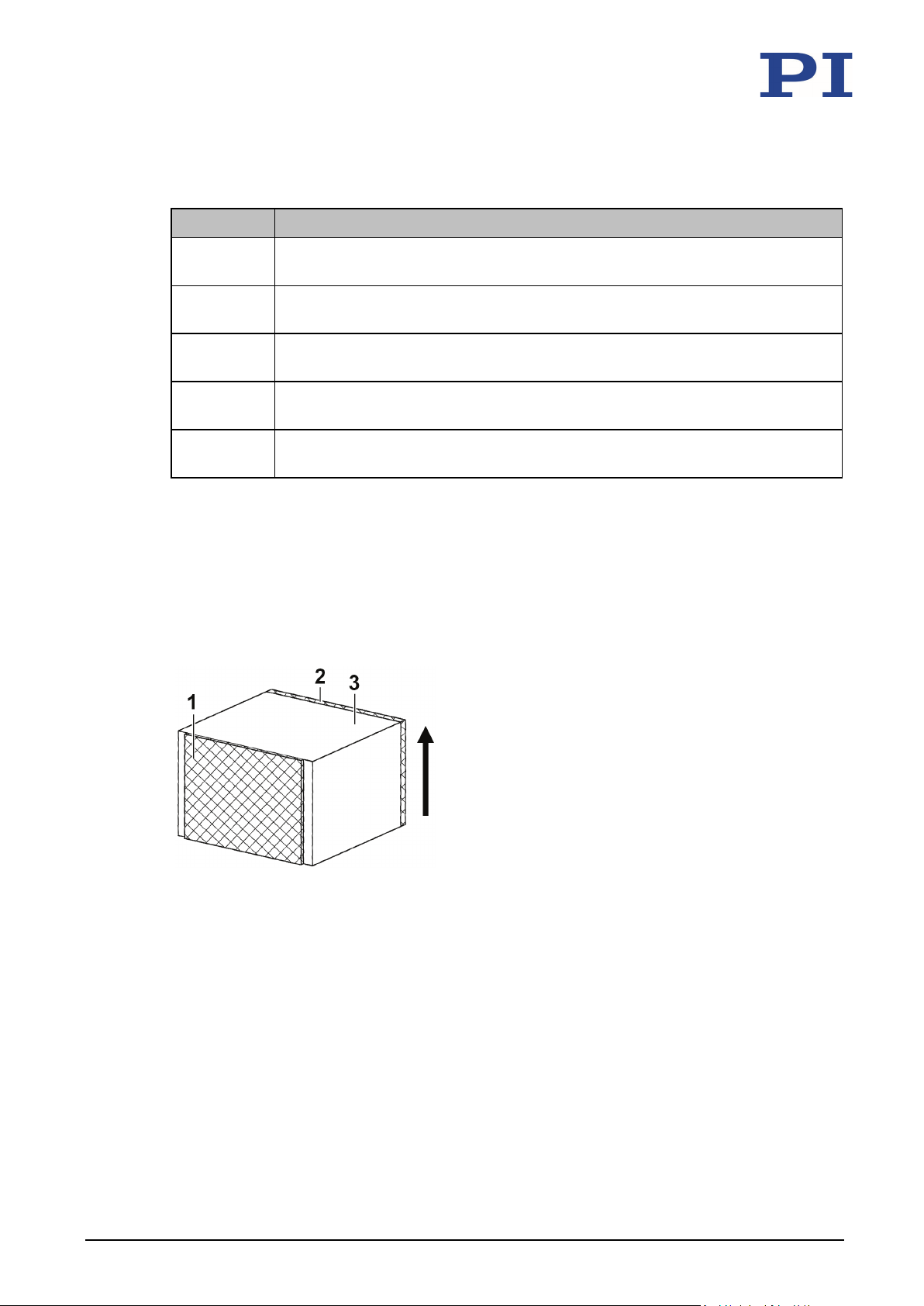
1:
Positive electrode: Voltage connection (+)
Round PICMA® Chip miniature multilayer piezo actuators with inner hole
Model Description
PD050.31 Round PICMA® Chip miniature piezo actuator with inner hole, 2.0 µm travel
range, OD 5 mm × ID 2.5 mm × TH 2.5 mm, stranded wires
PD080.31 Round PICMA® Chip miniature piezo actuator with inner hole, 2.0 µm travel
range, OD 8 mm × ID 4.5 mm × TH 2.5 mm, stranded wires
PD120.31 Round PICMA® Chip miniature piezo actuator with inner hole, 2.0 µm travel
range, OD 12 mm × ID 6 mm × TH 2.5 mm, stranded wires
PD150.31 Round PICMA® Chip miniature piezo actuator with inner hole, 1.8 µm travel
range, OD 15 mm x ID 9 mm x TH 2 mm, stranded wires
PD160.31 Round PICMA® Chip miniature piezo actuator with inner hole, 2.0 µm travel
range, OD 16 mm × ID 8 mm × TH 2.5 mm, stranded wires
All models are available with optional solderable contacts. The product numbers of the models
with solderable contacts end with the number 0 (e.g., PL022.30 or PD050.30).
3.2 Product View
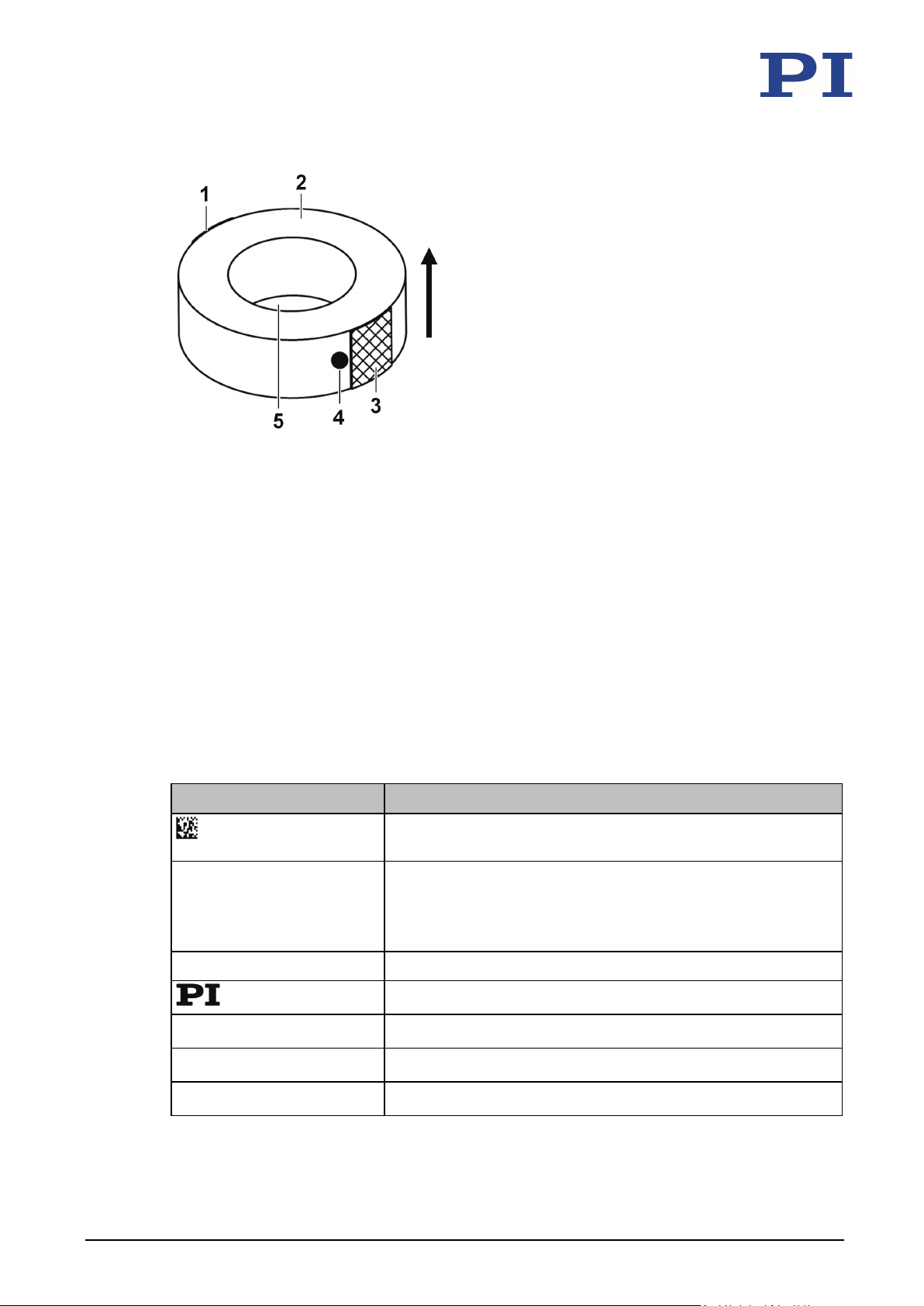
The figures serve as examples and can differ from your model. The models with stranded wires
(not shown) have a red stranded wire at the positive electrode (+) and a black stranded wire at
the negative electrode (-).
Figure 1: PL0xx: Example product view
The positive electrode does not cover the entire side surface.
2: Negative electrode: Connection for ground (-)
The negative electrode covers the entire side surface.
3: Ceramic end surface (passive PZT)
Arrow: Expansion direction of the piezo actuator when a positive voltage is applied
10 Version: 1.0.0 PZ265E PL0xx/PDxxx Piezo Actuator
Page 15
3 Product Description
Figure 2: PDxxx: Example product view of a model with inner hole
1: Negative electrode: Connection for ground (-)
2: Ceramic end surface (passive PZT)
3: Positive electrode: Voltage connection (+)
4: Point for identifying the positive electrode
5: Inner hole (depending on model type)
Arrow: Expansion direction of the piezo actuator when a positive voltage is applied
3.3 Product Labeling
Before delivery, each PL0xx/PDxxx is vacuum-packed in an ESD protective bag that prevents the
piezo actuator from being charged during transport. Larger actuators are additionally packed in
tubes to protect them against breakage.
Every ESD protection bag has a sticker with the following information:
Labeling Description
PL055.30 Product number (example), the digits after the period refer to
16CEP0653128979 Batch number (example), individual for each PL0xx/PDxxx
1 Stueck Quantity
Country of origin: Germany Country of origin
WWW.PICERAMIC.COM Manufacturer's address (website)
Data Matrix code (example; contains the abbreviated batch
number and the product number)
the model
The product number of custom products consists of nine digits
(without identification of the model).
Manufacturer's logo
PL0xx/PDxxx Piezo Actuator PZ265E Version: 1.0.0 11
Page 16

3 Product Description
3.4 Scope of Delivery
Product number Description
PL0xx/PDxxx Piezo actuator according to order (p. 9)
PZ264EK Short instructions for unhoused and encapsulated PICMA® piezo actuators
3.5 Suitable Electronics
To operate a PL0xx/PDxxx, you need electronics. The device is selected depending on the type
of application. The table below lists the suitable devices.
Product number Description
E-503 Piezo amplifier module (for E-500 piezo controller system)
E-504 Piezo amplifier module (for E-500 piezo controller system)
E-505 Piezo amplifier module (for E-500 piezo controller system)
E-506 Piezo charge amplifier (for E-500 piezo controller system)
E-610 Piezo amplifier / servo controller
E-617 High-performance piezo amplifier
E-618 High-performance piezo amplifier / servo controller
E-663 Piezo amplifiers
E-831 OEM piezo driver
E-836 Compact piezo amplifier / OEM module
To order, contact our customer service department (p. 47).
Before selecting electronics, calculate the power requirements of your application
(p. 39).
3.6 Accessories
Product number Description
P-890.10 Cable for piezo voltage, LEMO connector/open end, 1 m
P-890.20 Cable for piezo voltage, LEMO connector/open end, 5 m
The P-890.xx cable is for connecting the PL0xx/PDxxx to a low-voltage piezo amplifier with a
single-pole LEMO socket. The cable is soldered on the actuator side.
Connector: FFS.00.250.CTCE24
Cable: RG 178 (Teflon)
To order, contact our customer service department (p. 47).
12 Version: 1.0.0 PZ265E PL0xx/PDxxx Piezo Actuator
Page 17

3 Product Description
3.7 Technical Features
PICMA® piezo actuators
PL0xx/PDxxx are PICMA® multilayer piezo actuators for static and dynamic applications.
PICMA® actuators have all-ceramic insulation and their performance and lifetime are therefore
far superior to conventional actuators. The ceramic insulation layer protects the monolithic
piezoceramic block against humidity or failure due to increased leakage current. In this way, an
especially high reliability is achieved even under extreme ambient conditions.
PL0xx/PDxxx Piezo Actuator PZ265E Version: 1.0.0 13
Page 18

Page 19

4 Unpacking
4
Unpacking
NOTICE
Destruction of the piezo actuator due to contamination!
Contamination on the surface of the PL0xx/PDxxx can result in the destruction of the piezo
actuator by electric flashovers during operation.
When handling the piezo actuator, wear powder-free nitrile or latex gloves.
Prevent the piezo actuator from coming into contact with conductive liquids (e.g., finger
sweat) and conductive materials (e.g., metal dust).
If the piezo actuator has been accidentally contaminated, clean it in accordance with the
instructions in "Cleaning the PL0xx/PDxxx" (p. 43).
1. Unpack the PL0xx/PDxxx with care.
2. Compare the contents with the items listed in the contract and the packing list.
3. Inspect the contents for signs of damage. If there is any sign of damage or missing parts,
contact PI Ceramic immediately.
4. Keep all packaging materials in case the product needs to be returned.
PL0xx/PDxxx Piezo Actuator PZ265E Version: 1.0.0 15
Page 20

Page 21

5 Installation
Connecting the PL0xx/PDxxx to the Electronics .......................................................................... 29
5
Installation
In this Chapter
General Notes on Installation ...................................................................................................... 17
Connecting a Piezo Actuator with Stranded Wires (Only Models Without Stranded Wires) ...... 22
Mounting the PL0xx/PDxxx .......................................................................................................... 26
Applying a Preload ....................................................................................................................... 27
Applying the Load ........................................................................................................................ 28
5.1 General Notes on Installation
CAUTION
Dangerous voltage and residual charge in piezo actuators!
Temperature changes and compressive stresses can induce charges in the PL0xx/PDxxx piezo
actuator. After disconnection from the electronics, the piezo actuator can remain charged for
several hours. Touching the live parts of the PL0xx/PDxxx can result in minor injury from
electric shock.
Do not touch the piezo actuator unless it is discharged (p. 40).
When handling the piezo actuator, wear powder-free nitrile or latex gloves.
Keep the piezo actuator short-circuited (p. 41) when it is not connected to the electronics.
Do not disassemble the piezo actuator.
PL0xx/PDxxx Piezo Actuator PZ265E Version: 1.0.0 17
Page 22
5 Installation
that does not leave any scratches on the surface of the piezo actuator (e.g., conductive
NOTICE
Destruction of the piezo actuator due to rapid discharging!
If the piezo actuator is not connected to the electronics, it must be short-circuited in order to
prevent the piezo actuator from becoming charged during temperature changes and
compressive stresses. Unsuitable short-circuiting leads to an abrupt contraction of the piezo
actuator due to excessively fast discharging. Abrupt contraction can destroy the piezo actuator.
As soon as you have removed the piezo actuator from the conductive original packaging,
short-circuit it as follows:
− Models with stranded wires: Twist the stranded wires of the piezo actuator with each
− Models without stranded wires: Affix a suitable, conductive aid on the piezo actuator
Only disconnect the short-circuit connection of the piezo actuator if this is necessary for
installation or operation.
If the piezo actuator is not short-circuited:
− Ensure adequate protection against touching live parts.
− Discharge the piezo actuator in a suitable way before short-circuiting again (p. 40).
other.
rubber).
NOTICE
Destruction of the piezo actuator due to excessively high loads!
Excessive loads can destroy the PL0xx/PDxxx.
Do not exceed the maximum compressive/tensile stress capacity (p. 52).
NOTICE
Damage to the piezo actuator due to excessive preloading!
Excessive preloading can mechanically depolarize the piezo actuator. Depolarization damages
the piezo actuator.
Only apply preloads that are just as high as necessary.
Do not exceed the maximum preload (p. 52).
18 Version: 1.0.0 PZ265E PL0xx/PDxxx Piezo Actuator
Page 23
5 Installation
NOTICE
Destruction of the piezo actuator due to mechanical overload!
Torques and lateral forces can destroy the piezo actuator.
Avoid torques and lateral forces on the piezo actuator.
Make sure that the center of load of the moving system is on the motion axis of the piezo
actuator.
Avoid an uneven load distribution by using suitable structures or guide elements (e.g., ball
tips or flexure guides).
Establish contact over as large an area as possible on the end surfaces of the piezo
actuator, and select opposing surfaces with a flatness of only a few micrometers. Minor
unevenness can be compensated by full-surface gluing, for example.
NOTICE
Damage due to tensile stress on the stranded wires of the piezo actuators!
Impermissible forces on the stranded wires (if applicable) can damage the piezo actuator.
Avoid tensile stress on the stranded wires of the piezo actuator.
NOTICE
Damage due to scratches on the surface of the piezo actuator!
The surface of the piezo actuator is scratch-sensitive. Scratches on the surface can cause
damage to the piezo actuator.
Do not use metal tools to install the piezo actuator.
Install the piezo actuator so that the ceramic insulation and the end surfaces of the piezo
actuator are not scratched during installation and operation.
NOTICE
Heating up of the PL0xx/PDxxx during operation!
The heat produced during operation of the PL0xx/PDxxx can affect your application.
Install the PL0xx/PDxxx so that your application is not affected by the dissipating heat.
INFORMATION
Ground loops can occur when the piezo actuator is installed in a housing that is grounded via
the shield of the connecting cable of the piezo actuator as well as a separate protective earth
conductor.
If a ground loop occurs, contact our customer service department (p. 47).
PL0xx/PDxxx Piezo Actuator PZ265E Version: 1.0.0 19
Page 24
5 Installation
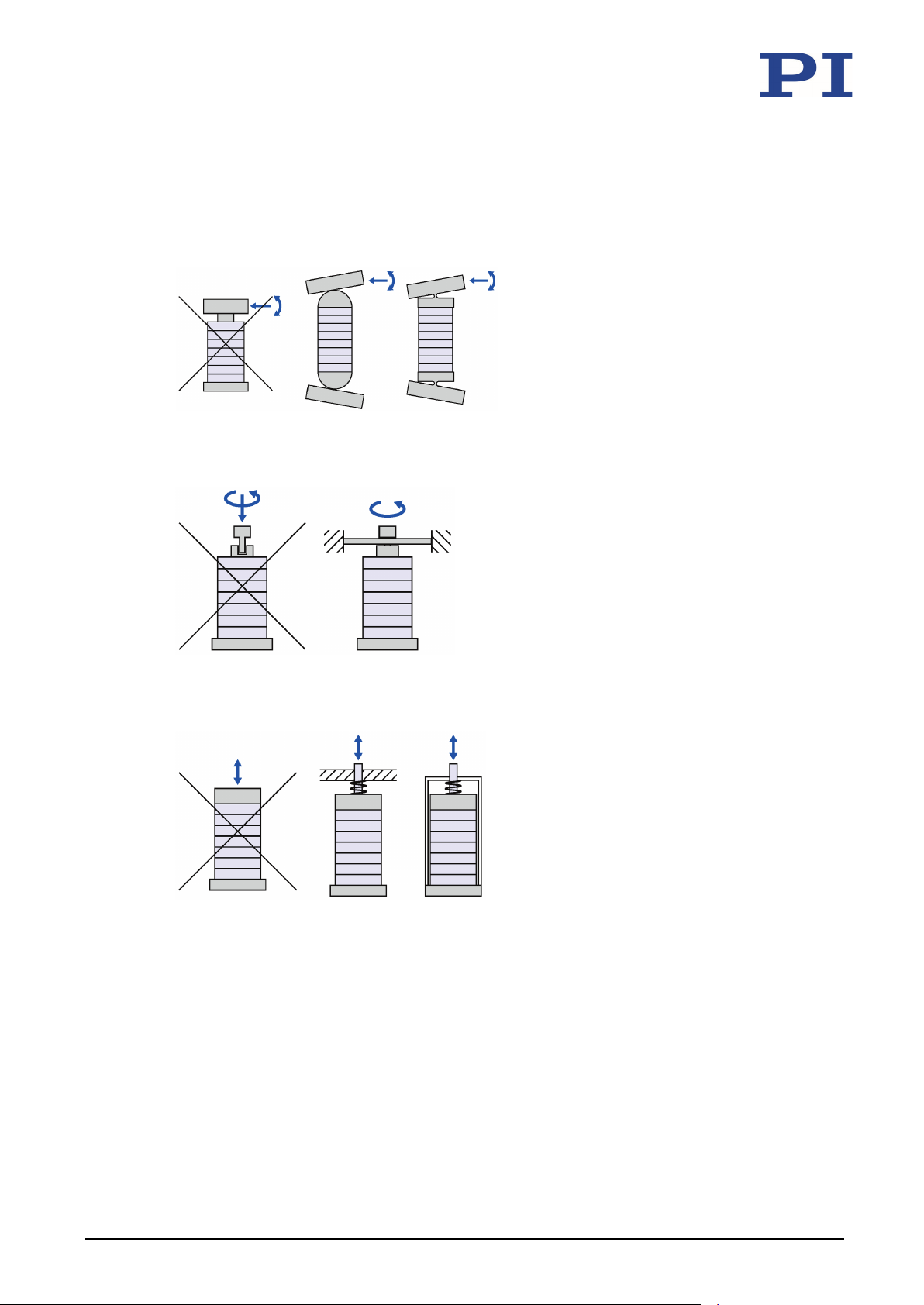
Piezo actuators may only be loaded axially. Moreover, piezo actuators should be preloaded
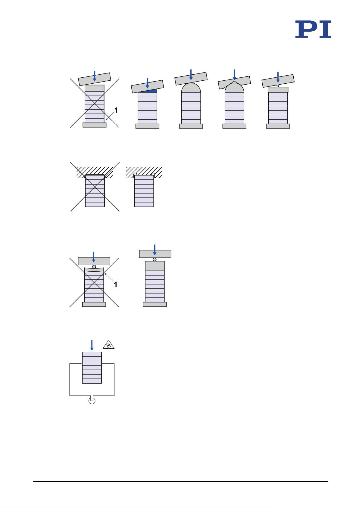
(p. 27) mechanically in order to avoid tensile stress. The following figures are to help you avoid
mounting errors.
Figure 3: Prevention of lateral forces and torques
Figure 4: Prevention of torques
Figure 5: Prevention of tensile stresses by means of a mechanical preload
20 Version: 1.0.0 PZ265E PL0xx/PDxxx Piezo Actuator
Page 25
5 Installation
Figure 6: Prevention of an irregular load application (1: Tensile stresses)
Figure 7: Full-area contact of the piezo actuator
Figure 8: Proper dimensioning of the end pieces in the case of point contact (1: Tensile stresses)
PL0xx/PDxxx Piezo Actuator PZ265E Version: 1.0.0 21
Figure 9: Mechanical or thermal loads electrically charge the piezo actuator. Mount only when short-
circuited.
Page 26
5 Installation
5.2 Connecting a Piezo Actuator with Stranded Wires (Only Models Without Stranded Wires)
The electrodes can make contact in one of the following ways:
Soldering the stranded wires (p. 22)
Gluing the stranded wires (p. 24)
If your application permits it, we recommend using models that already have stranded wires.
5.2.1 Soldering Stranded Wires to a Piezo Actuator (Only Models Without Stranded Wires)
NOTICE
Damage due to overheating of the piezo actuator during soldering!
Heat spreading from the piezo actuator that rises above the Curie temperature leads to
depolarization of the piezo ceramic. Depolarization can damage the piezo ceramic. Long and
repeated soldering processes can cause damage to the electrode.
The soldering temperature should not be any higher than necessary (max. 350 °C).
Make sure that the soldering time does not exceed one second.
Allow the solder point to cool down before resoldering.
NOTICE
Damage due to mechanical stress on the solder connection!
Mechanical stress on the solder connection due to moved stranded wires can damage the
piezo actuator.
Avoid tensile stress and shear forces on the solder connections.
22 Version: 1.0.0 PZ265E PL0xx/PDxxx Piezo Actuator
INFORMATION
The electrode marking is shown in the product view (p. 10).
Use a red stranded wire for the voltage connection (+).
Use a black stranded wire for ground (-).
Requirements
You have read and understood the general notes on installation (p. 17).
The PL0xx/PDxxx is discharged (p. 40) and short-circuited (p. 41).
Page 27
5 Installation
Tools and accessories
Suitable stranded wires that meet the applicable standards for the conditions of use
Suitable soldering iron
Suitable solder: Sn 95.5, Ag 3.8, Cu 0.7
Suitable flux according to one of the following standards:
− DIN EN 29454, part 1, category 1.1.3 or 1.2.3
− ANSI J-STD-004, flux type ROL0
Suitable cable tools
Soldering stranded wires to a piezo actuator (only models without stranded wires)
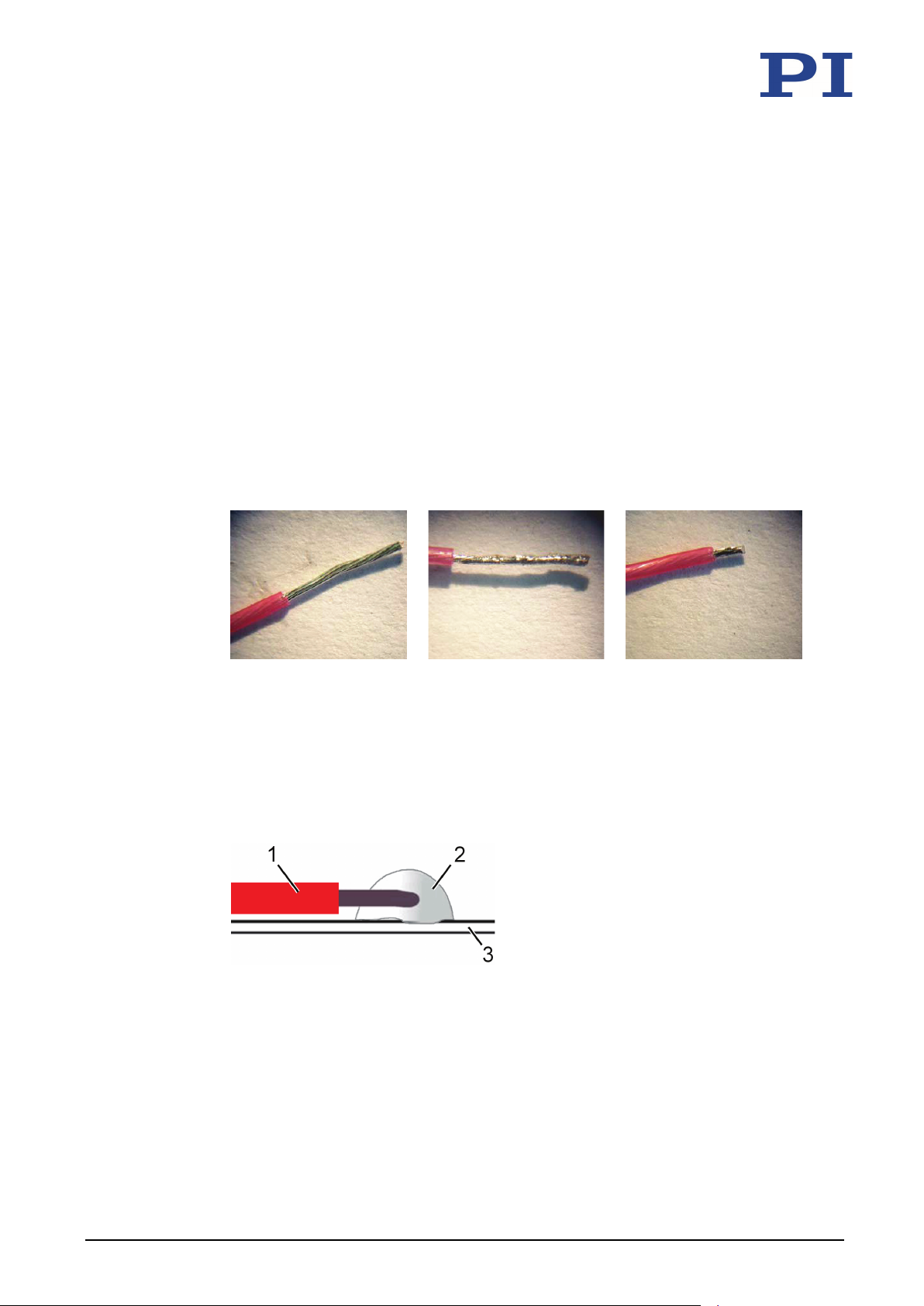
1. Prepare the stranded wire according to the following illustrations:
Twisting
Tinning
Shortening to 2 mm
2. Apply the flux to the tinned end of the wire and the intended soldering point of the
electrode.
3. Hold the stranded wire flat with the tinned end on the solder joint.
4. Coat the tip of the soldering iron with a small amount of solder.
5. Hold the tip of the soldering iron at the soldering point on the tinned end of the
stranded wire for a maximum of one second so that the solder flows and a flat or pointshaped solder connection results after soldering.
PL0xx/PDxxx Piezo Actuator PZ265E Version: 1.0.0 23
Figure 10: Solder connection [2] of stranded wire [1] and electrode [3]
6. Repeat steps 1 to 5 for the second stranded wire.
7. Remove flux residue according to the instructions in the section "Cleaning the
PL0xx/PDxxx" (p. 43).
Page 28
5 Installation
5.2.2 Gluing Stranded Wires to a Piezo Actuator (Only Models Without Stranded Wires)
CAUTION
Risk of electric shock when stranded wires become detached from the piezo actuator!
In the case of unsuitable adhesives or improper gluing, the adhesive connection can fail,
especially in the case of mechanical stress, causing stranded wires to become detached from
the actuator. If stranded wires detach from the piezo actuator during operation, touching the
stranded wires or other conductive parts that come into contact with them can cause minor
injuries from electric shock.
Use only suitable adhesives (e.g., electrically conductive, silver-filled epoxy resin adhesive)
to glue the stranded wires to the piezo actuator.
Use only suitable stranded wires that meet the applicable standards for the conditions of
use.
Make sure that the adhesion surfaces are dry, dust-free, and grease-free.
Avoid mechanical stress on the adhesive connections.
If stranded wires become detached during operation, switch off the electronics
immediately.
NOTICE
Damage due to mechanical stress on the adhesive connection!
Moving stranded wires can cause mechanical stress on the adhesive connection and damage
the piezo actuator.
Avoid tensile stress and shear forces on the adhesive connections.
NOTICE
Short-circuit damage due to improper gluing!
Improper gluing (e.g., unfavorable spreading of the electrically conductive adhesive) can cause
the piezo actuator and the connected electronics to be damaged by short-circuits.
When gluing the stranded wires to the electrodes, make sure that the adhesive does not
spread beyond the glueing point at any time.
INFORMATION
For optimum electrical contacting, it is recommended to use the following materials:
Silver-plated stranded wires
Electrically conductive, silver-filled epoxy resin adhesive
24 Version: 1.0.0 PZ265E PL0xx/PDxxx Piezo Actuator
Page 29

5 Installation
INFORMATION
The electrode marking is shown in the product view (p. 10).
Use a red stranded wire for the voltage connection (+).
Use a black stranded wire for ground (-).
Requirements
You have read and understood the general notes on installation (p. 17).
The PL0xx/PDxxx is discharged (p. 40) and short-circuited (p. 41).
You have read and understood the user information of the manufacturer of the
adhesive.
Tools and accessories
Suitable stranded wires that meet the applicable standards for the conditions of use
Electrically conductive, silver-filled epoxy resin adhesive
Suitable cable tools
Gluing stranded wires to a piezo actuator (only models without stranded wires)
1. If necessary, clean the bonding surfaces so that they are dry, dust-free and grease-free.
2. Remove the insulation at the end of the stranded wire to be glued and shorten the
stripped end to a length of 2 mm.
3. Glue the untwisted stranded wire on the electrode so that the glue does not flow
beyond the adhesive point at any time:
a) Apply the thinnest possible layer of adhesive to the adhesive point provided on the
electrode.
b) Apply a small amount of adhesive to the stripped end of the stranded wire.
c) Hold the stranded wire in the desired orientation on the adhesive point and fix the
stranded wire.
4. Repeat steps 2 and 3 for the second stranded wire.
5. Wait until the adhesive has completely hardened.
PL0xx/PDxxx Piezo Actuator PZ265E Version: 1.0.0 25
Page 30

5 Installation
5.3 Mounting the PL0xx/PDxxx
PL0xx/PDxxx piezo actuators are glued to metal or ceramic surfaces.
CAUTION
Risk of electric shock and short-circuit from incorrect gluing of the piezo actuator!
The electrodes of the piezo actuator extend to the ceramic end surfaces. If the piezo actuator
is glued to a conductive surface without insulation of the electrodes, the surface can be
electrically live during operation. Touching the surface or conductive parts connected can
result in minor injuries from electric shock. The electronics can be damaged by a short-circuit.
If the piezo actuator is to be glued to a conductive surface, insulate the surface from the
electrodes of the piezo actuator by suitable means:
− Place a nonconductive insulating layer on the surface
− Cut the surface to clear the entire area around the electrode
Requirements
You have read and understood the general notes on installation (p. 17).
The PL0xx/PDxxx is discharged (p. 40) and short-circuited (p. 41).
You have read and understood the user information of the manufacturer of the
adhesive.
Tools and accessories
Level surface that is dry, dust-free, and grease-free
Suitable adhesive (e.g., cold-hardening epoxy resin adhesive)
Mounting the PL0xx/PDxxx
1. Glue the piezo actuator to the surface:
− Apply the thinnest possible layer of adhesive.
− During the hardening process, maintain the operating temperature range (p. 53)
specified for the piezo actuator.
− Observe the temperature expansion coefficients of the materials involved.
2. Press the piezo actuator until the adhesive has hardened.
26 Version: 1.0.0 PZ265E PL0xx/PDxxx Piezo Actuator
Page 31

5 Installation
5.4 Applying a Preload
The tensile stress capacity of piezo actuators is relatively low. It is therefore recommended to
mechanically preload the piezo actuators in the application, either externally in the mechanical
structure or internally in a housing.
Requirements
You have read and understood the general notes on installation (p. 17).
The PL0xx/PDxxx is discharged (p. 40) and short-circuited (p. 41).
Tools and accessories
When installing in a housing: Suitable housing
Suitable guide elements
When creating the preload with a spring:
Suitable preload spring with the following characteristics:
− The stiffness of the preload spring does not exceed 10 % of the stiffness of the piezo
actuator. This is to minimize the displacement loss. If the stiffness of the preload
spring is equal to that of the actuator, the free displacement drops by half.
The stiffness of the piezo actuator can be calculated as follows:
kA Actuator stiffness
F
Blocking force*
max
ΔL
Nominal displacement*
0
* See data table (p. 49).
− With highly dynamic applications:
The resonant frequency (p. 49) of the preload spring exceeds that of the piezo
actuator.
Applying a preload
Apply the preload near the axis within the core cross section of the piezo actuator.
PL0xx/PDxxx Piezo Actuator PZ265E Version: 1.0.0 27
Page 32

5 Installation
5.5 Applying the Load
The PL0xx/PDxxx can be coupled to a load in various ways, depending on the application:
Gluing the piezo actuator (p. 26) into the mechanical system to be moved or into a
flexure
Using a ball tip:
− A hardened ball tip is glued to the ceramic end surface of the actuator; the ball tip
makes contact to the even surface at a single point
− A hardened ball tip is glued to the ceramic end surface of the actuator; the contact
area at the calotte is circular
INFORMATION
Diagrams showing how to couple the PL0xx/PDxxx to a load can be found in "General Notes on
Installation" (p. 17).
Requirements
You have read and understood the general notes on installation (p. 17).
The PL0xx/PDxxx is discharged (p. 40) and short-circuited (p. 41).
Tools and accessories
Suitable adhesive (e.g., cold-hardening epoxy resin adhesive)
When using a ball tip: Suitable ball tip
When using a flexure: Suitable flexure
Applying the load
Apply the load evenly.
If the piezo actuator is coupled in a milling pocket:
Ensure that there is full-area contact at the end surface of the piezo actuator. For this
purpose, choose the dimensions of the milling pocket correspondingly or make free
cuts in the milling pocket.
28 Version: 1.0.0 PZ265E PL0xx/PDxxx Piezo Actuator
If a point load is applied to the end piece of the piezo actuator:
Dimension the end piece so that its thickness corresponds to half the cross-sectional
dimension in order to prevent tensile stresses on the piezo actuator.
Page 33
5 Installation
5.6 Connecting the PL0xx/PDxxx to the Electronics
The PL0xx/PDxxx piezo actuator is connected to a LEMO socket, a terminal, or soldering pins,
depending on the electronics.
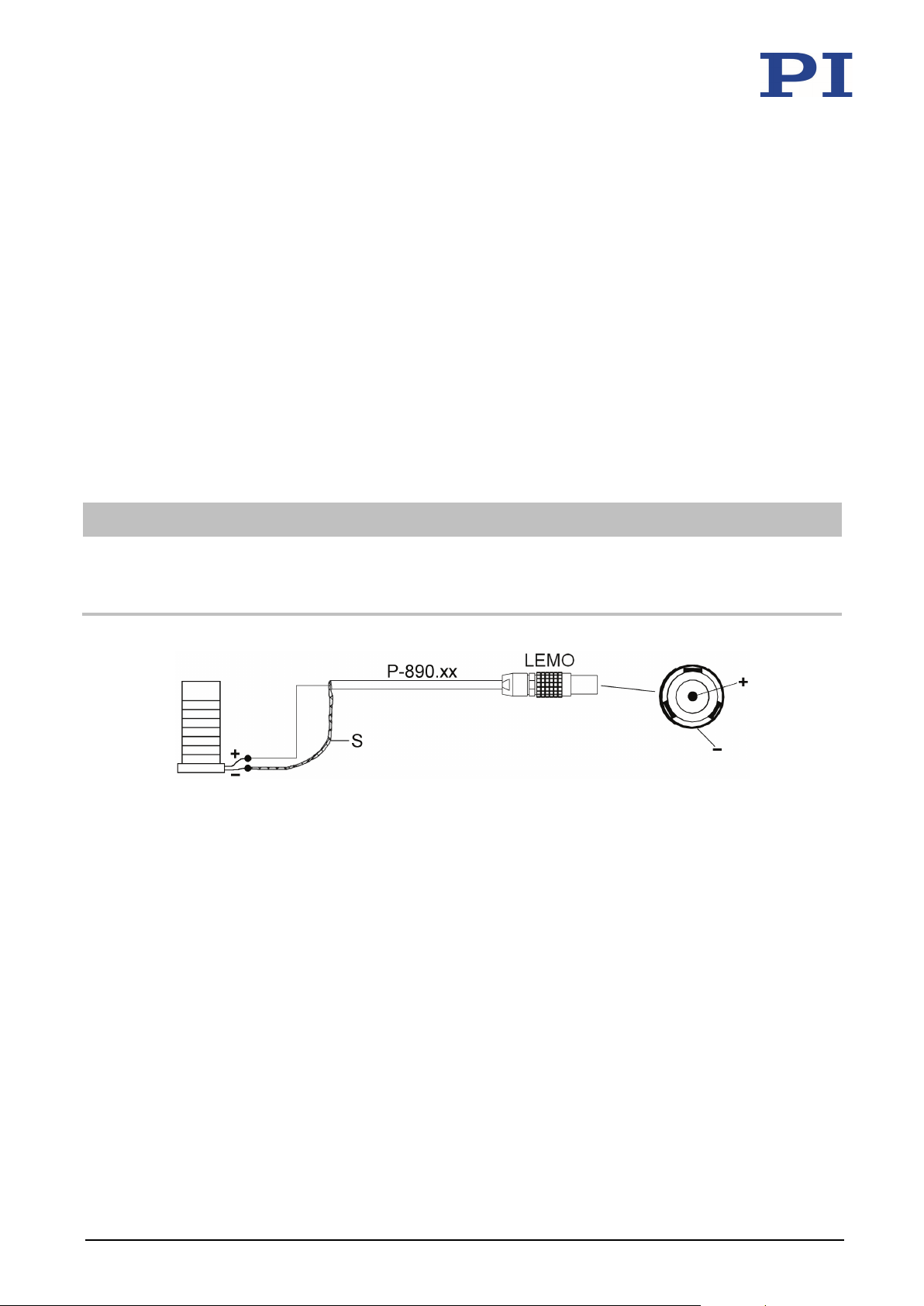
This section describes how the PL0xx/PDxxx piezo actuator is connected with the P-890.xx
coaxial cable to electronics with a single-pole LEMO socket.
If you use a self-made connecting cable instead of the P-890.xx coaxial cable for
connection to a single-pole LEMO socket, observe the relevant standards as well as the
assembly information of the manufacturer of the connector used.
For connection to the electronics with a two-pole LEMO socket, contact our customer
service department (p. 47).
For connection to terminals or solder pins, see the manual of the respective electronics
used (p. 3).
INFORMATION
The models with stranded wires have color-coded wires:
Red stranded wire: Voltage connection (+)
Black stranded wire: Ground (-)
Figure 11: Connection of the PL0xx/PDxxx piezo actuator to the P-890.xx coaxial cable
+ On the piezo actuator (left): Red stranded wire for voltage connection
On the LEMO connector (right): Inner contact for voltage connection
- On the piezo actuator (left): Black stranded wire for ground
On the LEMO connector (right): Connector housing
S Cable shield
LEMO LEMO connector, single-pole
PL0xx/PDxxx Piezo Actuator PZ265E Version: 1.0.0 29
Requirements
You have read and understood the general notes on installation (p. 17).
You have read and understood the user manual of the electronics used.
Page 34

5 Installation
If the PL0xx/PDxxx is not short-circuited: The PL0xx/PDxxx is discharged (p. 40).
The electronics are switched off.
The electronics have a single-pole LEMO socket.
Models without stranded wires: You have soldered (p. 22) or glued (p. 24) a red
stranded wire to the positive electrode (+) and a black stranded wire to the negative
electrode (-) of the PL0xx/PDxxx.
Tools and accessories
P-890.xx coaxial cable (p. 12), LEMO single-pole to open end (can be ordered
separately)
Suitable soldering iron
Suitable solder
Suitable cable tools
Connecting the PL0xx/PDxxx to the electronics
1. If necessary, shorten the wire and the cable shield of the coaxial cable to the correct
length.
2. Make the stranded wires of the PL0xx/PDxxx accessible:
− When the stranded wires of the PL0xx/PDxxx are short-circuited, disconnect the
connection between the stranded wires.
− Remove all aids and components that have been connected to the PL0xx/PDxxx for
short-circuiting or discharging (e.g., conductive rubber or discharging resistor).
3. Solder the red stranded wire of the PL0xx/PDxxx to the wire of the coaxial cable that is
connected to the inner contact of the LEMO connector.
4. Solder the black stranded wire of the PL0xx/PDxxx to the cable shield of the coaxial
cable.
5. Insulate the soldered cable connections in a suitable manner.
6. Connect the connector of the PL0xx/PDxxx to the corresponding connection on the
electronics.
30 Version: 1.0.0 PZ265E PL0xx/PDxxx Piezo Actuator
Page 35

6 Start-Up and Operation
Short-Circuiting the PL0xx/PDxxx ................................................................................................ 41
6
Start-Up and Operation
In this Chapter
General Notes on Start-Up and Operation .................................................................................. 31
Determining the Operating Parameters ...................................................................................... 35
Operating the PL0xx/PDxxx ......................................................................................................... 39
Discharging the PL0xx/PDxxx ....................................................................................................... 40
6.1 General Notes on Start-Up and Operation
CAUTION
Dangerous voltage in piezo actuators during operation!
During operation, the piezo actuator carries voltages of up to 100 V. Touching the piezo
actuator can lead to minor injuries from electric shock.
Do not touch the piezo actuator during operation.
Before start-up, insulate the piezo actuator electrically from the surrounding mechanical
system to prevent direct or indirect contact with live parts. Observe the clearances and
creepage distances required for the operating voltage, and observe the standards
applicable to your application.
CAUTION
Risk of electric shock if the protective earth conductor is not connected!
The system into which the piezo actuator is integrated (e.g., housing or surrounding
mechanical system) must be connected to a protective earth conductor. If the protective earth
conductor is not or not properly connected, touching the system in which the piezo actuator
was incorporated can lead to minor injury from electric shock in the case of a malfunction.
Before start-up, connect the overall system to a protective earth conductor in accordance
with the applicable standards.
Do not remove the protective earth conductor during operation.
If the protective earth conductor has to be temporarily removed (e.g., for modifications),
reconnect the overall system to the protective earth conductor before starting it up again.
PL0xx/PDxxx Piezo Actuator PZ265E Version: 1.0.0 31
Page 36
6 Start-Up and Operation
If sufficient cooling is not possible: Make sure that the hot PL0xx/PDxxx and its surrounding
ronments that increase the electrical conductivity can lead to the
CAUTION
Burning from hot surface!
The surface of the PL0xx/PDxxx and the surrounding area can heat up during operation.
Touching the PL0xx/PDxxx and surrounding parts can result in minor injuries from burning.
Cool the PL0xx/PDxxx so that the temperature of its surface and surrounding parts does
not exceed 65 °C. Do not use liquids for cooling. If liquid cooling is to be used, contact our
customer service department (p. 47).
parts cannot be touched.
If sufficient cooling and protection against contact are not possible: Mark the danger zone
in accordance with the legal regulations.
NOTICE
Destruction of the piezo actuator due to electric flashovers!
Using the PL0xx/PDxxx in envi
destruction of the piezo actuator by electric flashovers. Electric flashovers can be caused by
moisture, high humidity, liquids, and conductive materials (e.g., metal dust).
Avoid operating the PL0xx/PDxxx in environments that can increase the electrical
conductivity.
Only operate the PL0xx/PDxxx within the permissible ambient conditions and
classifications (p. 53).
Prevent the piezo actuator from coming into contact with liquids. If liquid cooling is to be
used, contact our customer service department (p. 47).
Protect the piezo actuator against moisture by means of hermetic sealing or the supply of
dry air.
If the PL0xx/PDxxx is to be operated in a special gas atmosphere, contact our customer
service department (p. 47).
NOTICE
Destruction of the piezo actuator by dynamic forces!
During dynamic operation, dynamic forces can occur that cancel the preload of the piezo
actuator. Operation without a preload can destroy the actuator.
Do not exceed the maximum compressive/tensile stress capacity (p. 52).
Observe the notes in "Determining the Operating Parameters" (p. 35).
32 Version: 1.0.0 PZ265E PL0xx/PDxxx Piezo Actuator
Page 37
6 Start-Up and Operation
In an arrangement with unilateral clamping, the value must be halved. For loaded piezo
NOTICE
Destruction of the piezo actuator due to excessive operating frequencies!
An excessive operating frequency can cause thermal and mechanical overloading that destroys
the piezo actuator.
Select the operating frequency so that the following conditions are met:
− The operating frequency of the piezo actuator does not exceed one third of the
− The dynamic forces occurring during operation do not exceed the maximum
Reduce the voltage at high operating frequencies to minimize the heating of the piezo
actuator.
If your application involves the operation of a piezo actuator which is not clamped on both
sides, contact our customer service department (p. 47).
resonant frequency. The resonant frequencies specified in the data tables (p. 49
) apply
to operation of the piezo actuator when it is unloaded and not clamped on both sides.
actuators that are clamped on one side, see "Calculating the Maximum Operating
Frequency of the Loaded Piezo Actuator" (p.
37).
tensile/compressive stress capacity of the piezo actuator (see "Calculating the Forces
that Occur During Dynamic Operation" (p. 38) and "Compressive/Tensile Stress
Capacity and Preload" (p. 52)).
NOTICE
Damage due to steep edges in the control signal!
If the actuator does not have a preload, steep edges in the control signal can trigger strong
dynamic forces which damage the piezo actuator. Steep edges can occur, for example, when
digital wave generators are switched on.
Avoid steep edges in the control signal on actuators with low preload.
NOTICE
Damage after reconnecting due to a charged piezo actuator!
The piezo actuator can remain charged if its connecting cable is pulled out of the electronics
during operation. Reconnecting a charged piezo actuator to electronics during operation can
cause a mechanical impulse that will damage the piezo actuator.
Do not pull the connecting cable of the piezo actuator out of the electronics during
operation.
If the connecting cable of the piezo actuator is accidentally pulled out of the electronics during
operation:
Switch off the electronics before you reconnect the piezo actuator.
PL0xx/PDxxx Piezo Actuator PZ265E Version: 1.0.0 33
Page 38
6 Start-Up and Operation
NOTICE
Reduced lifetime due to permanently high voltage and high air humidity!
The permanent application of a high static voltage to piezo actuators leads to a considerable
reduction in the lifetime of the piezo ceramic. This applies in particular to operation in a humid
environment.
When the PL0xx/PDxxx is not in use but the electronics remain switched on to ensure
temperature stability: Set the piezo voltage to 0 V on the electronics.
If possible: Limit the maximum operating voltage during continuous operation.
Reduce offset voltages to a minimum.
Protect the piezo actuator against moisture by means of hermetic sealing or the supply of
dry air.
Make sure that the air humidity in the vicinity of the PL0xx/PDxxx does not exceed the
relative humidity specified in "Ambient Conditions and Classifications" (p. 53).
NOTICE
Operating voltage excessively high or incorrectly connected!
Operating voltages that are too high or incorrectly connected can cause damage to the
PL0xx/PDxxx.
Do not exceed the operating voltage range (p. 51) for which the PL0xx/PDxxx is specified.
Operate the PL0xx/PDxxx only when the operating voltage is properly connected; see
"Connecting the PL0xx/PDxxx to the Electronics" (p. 29).
If you have accidently applied the operating voltage with the wrong polarity, contact our
customer service department (p. 47).
NOTICE
Destruction of the piezo actuator due to overheating!
During the operation of the piezo actuator, dielectric losses that are converted into heat
energy occur in the piezo ceramic due to ferroelectric polarization processes. The resulting
heat can overheat and destroy the piezo actuator, especially in dynamic operation.
Adjust the operating voltage, operating frequency, and/or operating time so that the
maximum operating temperature of the piezo actuator is not exceeded; see "Ambient
Conditions and Classifications" (p. 53), "Maximum Ratings" (p. 51), and "Determining the
Operating Parameters" (p. 35).
Cool the piezo actuator. Do not use liquids for cooling. If liquid cooling is to be used,
contact our customer service department (p. 47).
34 Version: 1.0.0 PZ265E PL0xx/PDxxx Piezo Actuator
Page 39

6 Start-Up and Operation
For determination of the the operating parameters, it is assumed that the piezo actuator is
NOTICE
Destruction of the piezo actuator due to rapid cooling or heating!
Cooling down or heating up too quickly leads to a thermomechanical overload that can destroy
the piezo actuator.
Allow the piezo actuator to cool down or warm up slowly.
NOTICE
Uncontrolled oscillation!
Oscillation can cause irreparable damage to the piezo actuator. Oscillation is indicated by a
humming and can be caused by the following:
A change in the load and/or dynamics requires the servo-control parameters to be
adjusted.
The piezo actuator is operated near to its resonant frequency.
If you notice oscillation:
In closed-loop operation, immediately switch off the servo mode.
In open-loop operation, immediately stop the piezo actuator.
INFORMATION
The positive direction of motion (p. 10) corresponds to the expansion direction of the piezo
actuator when a positive voltage is applied.
6.2 Determining the Operating Parameters
INFORMATION
clamped on one side.
If you require operating parameters for unclamped operation of the piezo actuator,
contact our customer service department (p. 47).
PL0xx/PDxxx Piezo Actuator PZ265E Version: 1.0.0 35
Page 40

6 Start-Up and Operation
6.2.1 Overview of Limiting Factors
Limiting factors for the operation of the piezo actuator:
Resonant frequency:
The resonant frequency of the piezo actuator serves as a basis for calculating the operating
frequency, which must not exceed one third of the resonant frequency. The resonant
frequencies given in the data tables (p. 49) apply to operation of the piezo actuator when it
is unloaded and not clamped on both sides. In an arrangement with unilateral clamping, the
value has to be divided in half.
For loaded piezo actuators that are clamped on one side, see "Calculating the Maximum
Operating Frequency of the Loaded Piezo Actuator" (p. 37).
Maximum compressive/tensile stress capacity (p. 52):
The mass of the load to be moved, the preload, and the operating frequency of the piezo
actuator must be selected so that the dynamic forces occurring during operation do not
exceed the maximum tensile/compressive stress capacity of the piezo actuator. See
"Calculating the Forces that Occur During Dynamic Operation" (p. 38).
Maximum permissible operating temperature of the piezo actuator (p. 53):
The greater the operating frequency, the operating voltage (peak-to-peak), and the
capacitance of the piezo actuator, the greater the thermal power generated in the piezo
actuator. The operating frequency, operating voltage and operating time must be selected
so that the maximum permissible operating temperature of the piezo actuator is not
exceeded. For the maximum permissible operating frequency without cooling, see column B
of the table in "Maximum Ratings" (p. 51).
When cooling measures are used, the limit values for the operating frequency, operating
voltage and operating time increase.
Peak and average output current of the electronics (p. 12) used:
The electronics must be selected so that it fulfills the following requirements:
− The electronics can provide the required current. See "Calculating the Power
Requirement for Sinusoidal Operation" (p. 39).
− The output current of the electronics does not exceed the maximum power
consumption of the piezo actuator. See "Maximum Ratings" (p. 51).
− The control signal of the electronics does not have steep edges. See "General Notes
on Start-Up and Operation" (p. 31).
36 Version: 1.0.0 PZ265E PL0xx/PDxxx Piezo Actuator
Page 41
6 Start-Up and Operation
In the following calculation, the maximum permissible operating temperature of the piezo
6.2.2 Calculating the Effective Mass
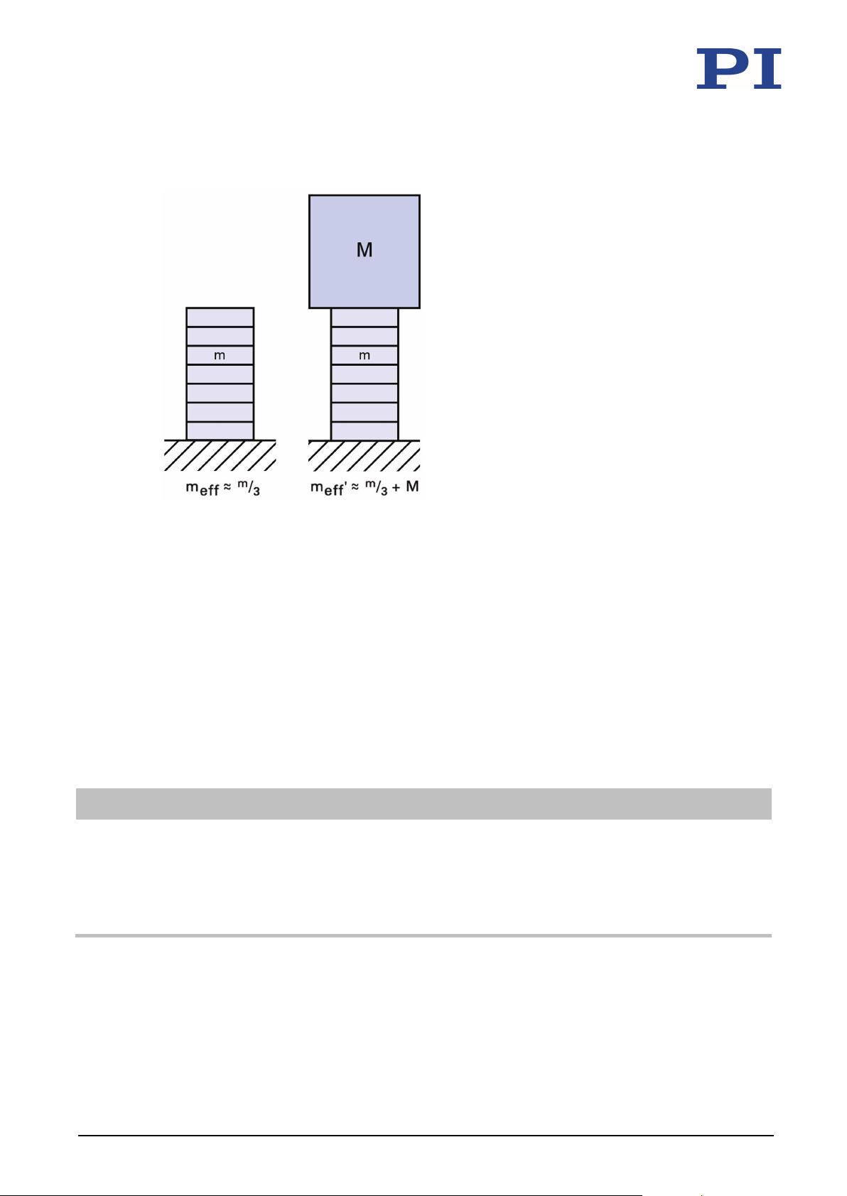
Figure 12: Calculation of the effective mass of a unilaterally clamped piezo stack actuator without load
(left) and with additional load (right).
1. Determine the mass m of your piezo actuator.
2. Determine the additional load M.
3. Calculate the effective mass m
of the unloaded piezo actuator and m
eff
' of the loaded
eff
piezo actuator using the formulas in the figure above.
6.2.3 Calculating the Maximum Operating Frequency of the Loaded Piezo Actuator
INFORMATION
actuator is not taken into account. During operation without cooling, the maximum operating
temperature may already be exceeded when the operating frequency is still below the limit
value calculated in the following.
For the maximum permissible operating frequency without cooling, see column B of the
table in "Maximum Ratings" (p. 51).
PL0xx/PDxxx Piezo Actuator PZ265E Version: 1.0.0 37
Page 42

6 Start-Up and Operation
1. Calculate the resonant frequency of the loaded, unilaterally clamped piezo actuator
using the following formula:
f
' = Resonant frequency of the loaded piezo actuator [Hz]
0
f
= Resonant frequency of the unloaded piezo actuator [Hz]: The resonant frequencies
0
given in the data tables (p. 49) apply to unclamped operation. In an arrangement with
unilateral clamping, the value must be halved.
m
= Effective mass; approx. 1/3 of the mass of the piezo actuator [kg]
eff
m
' = Effective mass m
eff
+ additional load M [kg]
eff
See also "Calculating the Effective Mass" (p. 37).
2. Calculate the maximum operating frequency of the loaded, unilaterally clamped piezo
actuator using the following formula:
f
= f0'/3
max
f
= Maximum operating frequency of the loaded piezo actuator [Hz]
max
f
' = Resonant frequency of the loaded piezo actuator [Hz]
0
6.2.4 Calculating the Forces that Occur During Dynamic Operation
Calculate the dynamic forces acting on the unilaterally clamped piezo actuator during
sinusoidal operation at the frequency f using the following formula:
F
= Dynamic force [N]
dyn
m
' = Effective mass m
eff
load M [kg], see also "Calculating the Effective Mass" (p. 37)
ΔL = Displacement in the application (peak-to-peak) [m]
f = Frequency [Hz]
Example: The dynamic forces at 1000 Hz, 2 μm displacement (peak-to-peak) and 1 kg
effective mass are approximately ±40 N.
(approx. 1/3 of the mass of the piezo actuator) + additional
eff
38 Version: 1.0.0 PZ265E PL0xx/PDxxx Piezo Actuator
Page 43

6 Start-Up and Operation
Required peak current of the amplifier
6.2.5 Calculating the Power Requirement for Sinusoidal Operation
Calculate the average current requirement for sinusoidal operation using the following
formula:
Calculate the peak current requirement for sinusoidal operation using the following
formula:
Variable Description Notes
Ia Required average current of the
amplifier (source / sink) [A]
I
max
(source / sink) [A]
f Operating frequency [Hz] Details on the operating frequency see
C Capacitance of the piezo actuator
[F (= As/V)]
U
Operating voltage (peak-to-peak) [V] Voltage difference between positive and
p-p
6.3 Operating the PL0xx/PDxxx
Requirements
It is essential that the power supply can
supply enough current.
The provided peak current depends on
the internal storage capacity of the
amplifier.
"Overview of Limiting Factors" (p. 36).
See "Data Table" (p. 49) for the smallsignal capacitance of the piezo actuator.
For large-signal conditions, a safety factor
of 70 % should be added to the smallsignal capacitance.
negative peak voltage
You have read and understood the general notes on start-up and operation (p. 31).
You have determined the operating parameters for your application (p. 35).
You have installed (p. 17) the PL0xx/PDxxx correctly and connected it to the electronics
(p. 29).
You have provided suitable electronics that can supply the required currents (p. 39).
You have read and understood the user manual of the electronics used.
Operating the PL0xx/PDxxx
For starting up and operating the PL0xx/PDxxx, follow the instructions in the manual of
the electronics (p. 3) used.
PL0xx/PDxxx Piezo Actuator PZ265E Version: 1.0.0 39
Page 44

6 Start-Up and Operation
6.4 Discharging the PL0xx/PDxxx
The PL0xx/PDxxx must be discharged in the following cases:
If the PL0xx/PDxxx has become accidentally charged due to thermal or mechanical
loading
If a charged PL0xx/PDxxx is to be short-circuited (p. 41)
If the connecting cable of the PL0xx/PDxxx is accidentally pulled out of the electronics
during operation
Requirements
You have read and understood the general notes on installation (p. 17).
Tools and accessories
If the PL0xx/PDxxx is not connected to the electronics:
Only for PL0xx/PDxxx without connector (condition as supplied):
− 10 kΩ discharge resistor (not included in scope of delivery); touchable parts must be
adequately insulated for the operating voltage range (p. 51) of the actuator
Only for PL0xx/PDxxx with connector (p. 29):
− Electronics (p. 12) from PI
Discharging a PL0xx/PDxxx connected to the electronics
Set the piezo voltage to 0 V on the electronics.
Discharging a PL0xx/PDxxx not connected to the electronics
If the PL0xx/PDxxx does not have a connector:
1. If necessary, let the PL0xx/PDxxx cool down.
2. Ensure adequate protection against touching live parts.
3. Short-circuit the electrodes of the PL0xx/PDxxx for at least a few seconds using a 10 kΩ
discharge resistor.
If the PL0xx/PDxxx has a connector:
Connect the voltage connector of the PL0xx/PDxxx to the switched-off PI electronics,
which has an internal discharge resistor, for at least a few seconds.
40 Version: 1.0.0 PZ265E PL0xx/PDxxx Piezo Actuator
Page 45

6 Start-Up and Operation
6.5 Short-Circuiting the PL0xx/PDxxx
The PL0xx/PDxxx must be discharged (p. 40) and short-circuited before demounting (e.g.,
before cleaning and transportation of the PL0xx/PDxxx) as well as for modifications.
Requirements
You have read and understood the general notes on installation (p. 17).
You have discharged the PL0xx/PDxxx and disconnected it from the electronics.
Tools and accessories
If no open stranded wires are accessible on the piezo actuator: Suitable conductive aid
for short-circuiting the piezo actuator that does not scratch the surface of the piezo
actuator (e.g., conductive rubber)
Short-circuiting the PL0xx/PDxxx
If bare stranded wires are accessible on the PL0xx/PDxxx:
Twist the stranded wires of the discharged piezo actuator with each other.
If no bare stranded wires are accessible on the PL0xx/PDxxx:
a) If necessary, let the PL0xx/PDxxx cool down.
b) Affix a suitable, conductive aid on the discharged piezo actuator that does not
scratch the surface of the piezo actuator (e.g., conductive rubber).
PL0xx/PDxxx Piezo Actuator PZ265E Version: 1.0.0 41
Page 46

Page 47

7 Maintenance
Cleaning the PL0xx/PDxxx ............................................................................................................ 43
inutes at
7
Maintenance
In this Chapter
General Notes on Maintenance ................................................................................................... 43
7.1 General Notes on Maintenance
The PL0xx/PDxxx is maintenance-free.
7.2 Cleaning the PL0xx/PDxxx
NOTICE
Destruction of the piezo actuator due to electric flashovers!
If the piezo actuator comes into contact with liquids, it can be destroyed by electric flashovers.
Before cleaning the PL0xx/PDxxx:
Ensure that the PL0xx/PDxxx is discharged (p. 40) and short-circuited (p. 41).
After cleaning the PL0xx/PDxxx:
Dry the PL0xx/PDxxx completely in a drying cabinet (recommended duration: 30 m
40 °C).
Requirements
The PL0xx/PDxxx is discharged (p. 40) and short-circuited (p. 41).
The PL0xx/PDxxx is disconnected from the electronics.
Cleaning the PL0xx/PDxxx
Touch the piezo actuator only with powder-free nitrile or latex gloves.
Do not use acetone and do not use water for cleaning.
When necessary, clean the surfaces of the PL0xx/PDxxx with a lint-free cloth that is
slightly dampened with a mild cleanser (e.g., isopropanol or ethanol).
PL0xx/PDxxx Piezo Actuator PZ265E Version: 1.0.0 43
Page 48

7 Maintenance
When cleaning in an ultrasonic bath:
− Reduce the energy input to the necessary minimum.
− Only use isopropanol or ethanol as cleaning fluid.
− Observe a cleaning time of 5 minutes.
After cleaning, dry the PL0xx/PDxxx completely in a drying cabinet (recommended
duration: 30 minutes at 40 °C).
44 Version: 1.0.0 PZ265E PL0xx/PDxxx Piezo Actuator
Page 49

8 Troubleshooting
8
Troubleshooting
Problem Possible causes Solution
No or limited motion Cable not connected
correctly
Excessive load
Piezo actuator is
depolarized due to
overheating or reverse
polarity
Piezo actuator moves in
the opposite direction to
that specified when
voltage increases
If the problem that occurred with your system is not listed in the table above or cannot be
solved as described, contact our customer service department (p. 47).
Reverse polarity of the
piezo actuator
Check the cable connections.
Do not exceed the maximum
compressive/tensile stress capacity
52).
(p.
Contact our customer service
department (p.
Contact our customer service
department (p.
47).
47).
PL0xx/PDxxx Piezo Actuator PZ265E Version: 1.0.0 45
Page 50

Page 51

9 Customer Service
9
Customer Service
You can contact PI Ceramic by telephone under +49 36604 882-0 or by email at the following
address:
For general questions or for orders:
In the case of technical problems or faults:
If you have questions concerning your product, provide the following information:
− Product and serial numbers of all products concerned
− Firmware version of the electronics (if present)
− Version of the driver or the software (if present)
− Operating system on the PC (if present)
If possible: Take photographs or make videos of your system that can be sent to our
customer service department if requested
The latest versions of the user manuals are available for download (p. 3) on our website.
PL0xx/PDxxx Piezo Actuator PZ265E Version: 1.0.0 47
Page 52

Page 53

10 Technical Data
Dimensions .................................................................................................................................. 54
10
Technical Data
In this Chapter
Specifications ............................................................................................................................... 49
10.1 Specifications
10.1.1 Data Table
PICMA® Chip multilayer piezo actuators
Side length (A) 2 ±0.10 3 ±0.10 5 ±0.15 10 ±0.20 mm
Side length (B) 2 ±0.10 3 ±0.10 5 ±0.15 10 ±0.20 mm
Height (TH) 2 ±0.10 2 ±0.10 2 ±0.10 2 ±0.10 mm
Travel range* 2.2 2.2 2.2 2.2 µm ±20 %
Blocking force** >120 >300 >500 >2000 N
Electrical capacitance*** 25 85 250 1100 nF ±20 %
Axial resonant frequency**** >600 >600 >600 >600 kHz
Piezo ceramic PIC252 PIC252 PIC252 PIC252
Operating voltage range -20 to 100 -20 to 100 -20 to 100 -20 to 100 V
Operating temperature range -40 to 150 -40 to 150 -40 to 150 -40 to 150 °C
Recommended preload for dynamic
operation
Maximum preload for constant force 30 30 30 30 MPa
Standard connections: PL0xx.31: PTFE-insulated stranded wires, 100 mm, AWG 32, Ø 0.49 mm; PL0xx.30:
Solderable contacts
* At 0 to 100 V. The values refer to the unattached component and can be lower when glued on.
** At 0 to 100 V
PL022.3x PL033.3x PL055.3x PL088.3x Unit Tolerance
15 15 15 15 MPa
*** Measured at 1 V
**** Measured at 1 V
the installation situation, the lateral resonant frequencies can be lower than the axial resonant
frequencies.
Ask about custom designs!
, 1 kHz, RT
pp
, unloaded, unclamped. The value is halved for unilateral clamping. Depending on
pp
PL0xx/PDxxx Piezo Actuator PZ265E Version: 1.0.0 49
Page 54

10 Technical Data
PICMA® Chip multilayer piezo actuators with and without inner hole
PD050
.3x
PD080
.3x
PD120
.3x
PD150
.3x
PD160
.3x
PD161
.3x
Unit Tolerance
Outer diameter (OD) 5 ±0.2 8 ±0.3 12 ±0.4 15 ±0.3 16 ±0.5 16 ±0.5 mm
Inner diameter (ID) 2.5 ±0.15 4.5 ±0.15 6 ±0.2 9 ±0.15 8 ±0.25 – mm
Height (TH) 2.5 ±0.05 2.5 ±0.05 2.5 ±0.05 2 ±0.05 2.5 ±0.05 2.5 ±0.05 mm
Travel range* 2 2 2 1.8 2 2.3 µm ±20 %
Blocking force** >400 >1000 >2500 >3300 >4400 >6000 N
Electrical
110 300 900 1000 1700 2400 nF ±20 %
capacitance***
Axial resonant
>500 >500 >500 >600 >500 >500 kHz
frequency****
Piezo ceramic PIC252 PIC252 PIC252 PIC252 PIC252 PIC252
Operating voltage
range
Operating
temperature range
Recommended
-20 to
100
-40 to
150
-20 to
100
-40 to
150
-20 to
100
-40 to
150
-20 to
100
-40 to
150
-20 to
100
-40 to
150
-20 to
100
-40 to
150
15 15 15 15 15 15 MPa
V
°C
preload for dynamic
operation
Maximum preload for
constant force
30 30 30 30 30 30 MPa
Standard connections: PDxxx.31: PTFE-insulated stranded wires, 100 mm, AWG 32, Ø 0.49 mm; PDxxx.30:
Solderable contacts
* At 0 to 100 V. The values refer to the unattached component and can be lower when glued on.
** At 0 to 100 V
*** Measured at 1 V
**** Measured at 1 V
, 1 kHz, RT
pp
, unloaded, unclamped. The value is halved for unilateral clamping. Depending on
pp
the installation situation, the lateral resonant frequencies can be lower than the axial resonant
frequencies.
Ask about custom designs!
50 Version: 1.0.0 PZ265E PL0xx/PDxxx Piezo Actuator
Page 55
10 Technical Data
10.1.2 Maximum Ratings
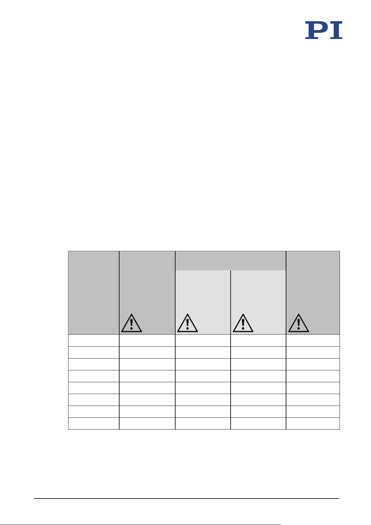
PL0xx/PDxxx piezo actuators are designed for the operating data specified in the table below.
Additional information on the maximum ratings table
Maximum operating frequency without load, without considering thermal aspects,
column A:
The values apply to unilaterally clamped piezo actuators and are calculated as follows: A
third of the resonant frequency of the unloaded piezo actuator (operation when not
clamped on both sides) divided by two.
Maximum operating frequency without load, considering thermal aspects, column B:
In order to prevent the maximum permissible operating temperature from being exceeded,
the operating frequency of the unloaded, uncooled piezo actuator must not exceed the
specified frequency when the operating voltage is 120 V peak-to-peak. In the case of
smaller amplitudes of the operating voltage and/or the use of cooling measures, higher
operating frequencies are possible.
Maximum power consumption:
Power consumption of the unloaded, uncooled piezo actuator that is operated at a voltage
of 120 V peak-to-peak with the operating frequency from column B of this table.
Piezo actuator* Maximum
operating voltage
range
Without
PL022.3x –20 V to 100 V 100 kHz 290 Hz 0.1 W
PL033.3x –20 V to 100 V 100 kHz 130 Hz 0.2 W
PL055.3x –20 V to 100 V 100 kHz 80 Hz 0.4 W
PL088.3x –20 V to 100 V 100 kHz 40 Hz 0.8 W
PD050.3x –20 V to 100 V 83.3 kHz 160 Hz 0.3 W
Maximum operating frequency
without load
A: B:
Considering
considering
thermal aspects
thermal aspects
Maximum power
consumption
Considering
thermal aspects
PL0xx/PDxxx Piezo Actuator PZ265E Version: 1.0.0 51
PD080.3x –20 V to 100 V 83.3 kHz 100 Hz 0.6 W
PD120.3x –20 V to 100 V 83.3 kHz 50 Hz 0.9 W
PD150.3x –20 V to 100 V 100 kHz 50 Hz 1.0 W
Page 56
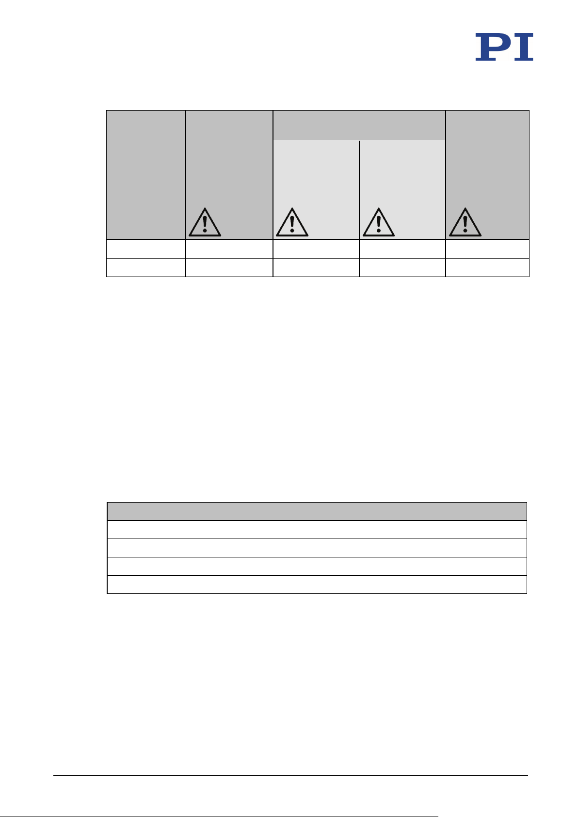
10 Technical Data
Piezo actuator* Maximum
operating voltage
range
Without
Maximum operating frequency
without load
A: B:
Considering
considering
thermal aspects
thermal aspects
PD160.3x –20 V to 100 V 83.3 kHz 40 Hz 1.3 W
PD161.3x –20 V to 100 V 83.3 kHz 30 Hz 1.4 W
* The letter x in the product number of the piezo actuator stands for the model:
1: Models with stranded wires
0: Models without stranded wires
10.1.3 Compressive/Tensile Stress Capacity and Preload
Piezo ceramic withstands a pressure of up to 250 MPa but starts to depolarize at significantly
lower compressive loads. Since stacked piezo actuators are also made of different materials
(piezo ceramic, metallic electrodes), the mechanical load capacity does not depend solely on
the strength of the ceramic material. Consideration must be given to additional parameters
such as slenderness ratio, bending, tilt and homogeneity of the force application.
Maximum power
consumption
Considering
thermal aspects
The tensile stress capacity of piezo actuators is just 5 to 10 % of the compressive load capacity.
It is therefore recommended to mechanically preload the actuators. The preload should be
chosen only as high as necessary.
Compressive/tensile stress capacity and preload of the PL0xx/PDxxx
Type of mechanical stress PL0xx/PDxxx*
Maximum compressive load capacity 30 MPa
Maximum tensile stress capacity without preload 2 MPa**
Recommended preload for dynamic operation 15 MPa
Maximum preload for constant force 30 MPa
* 1 MPa corresponds to a pressure of 1 N per square millimeter of the base area of the piezo
actuator. Dimensions see data table (p. 49).
** Depends on the strength of the glued connections (p. 26)
52 Version: 1.0.0 PZ265E PL0xx/PDxxx Piezo Actuator
Page 57

10 Technical Data
10.1.4 Ambient Conditions and Classifications
The following ambient conditions and classifications for the PL0xx/PDxxx must be observed:
Area of application For indoor use only
Air pressure 500 hPa to 1500 hPa
If you want to operate the PL0xx/PDxxx outside of the
specified air pressure range, contact our customer service
department (p. 47).
Relative humidity Maximum relative humidity 55 %
Continuous operation with high static voltage in humid
environments significantly reduces piezo actuator lifetime.
If you want to operate the PL0xx/PDxxx at a relative
humidity of more than 55 %, contact our customer service
department (p. 47).
Observe the information on service life, which can be found
here:
− Section "General Notes on Start-Up and Operation"
(p. 31)
− Internet site of PI Ceramic (www.piceramic.com/piezo-
technologie/picma.html)
Operating temperature –40 °C to 150 °C
Storage temperature –40 °C to 80 °C
Transport temperature –40 °C to 80 °C
Overvoltage category II
Degree of pollution 1
The PL0xx/PDxxx is intended for installation in devices that fulfil the following classifications:
Protection class I
Degree of protection
IP20
according to IEC 60529
PL0xx/PDxxx Piezo Actuator PZ265E Version: 1.0.0 53
Page 58
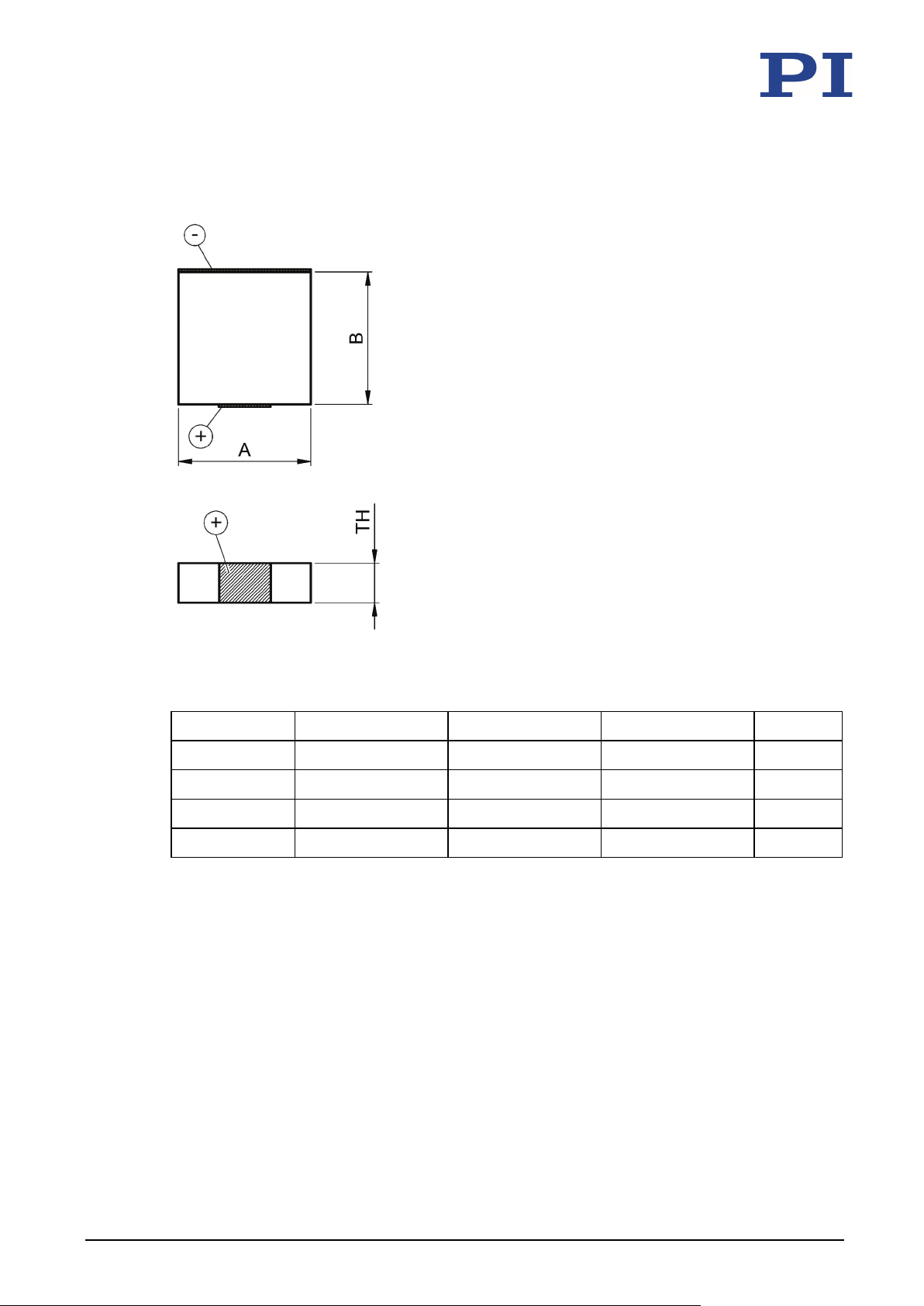
10 Technical Data
10.2 Dimensions
Figure 13: PL0xx: Dimensions
Model Length A Length B Height TH Unit
PL022.3x 2 (±0.10) 2 (±0.10) 2 (±0.10) mm
PL033.3x 3 (±0.10) 3 (±0.10) 2 (±0.10) mm
PL055.3x 5 (±0.15) 5 (±0.15) 2 (±0.10) mm
PL088.3x 10 (±0.20) 10 (±0.20) 2 (±0.10) mm
54 Version: 1.0.0 PZ265E PL0xx/PDxxx Piezo Actuator
Page 59
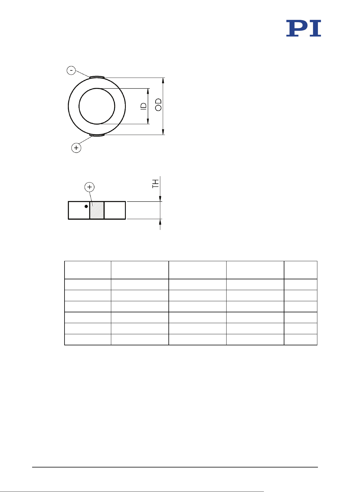
10 Technical Data
Figure 14: PDxxx: Dimensions (end surfaces of the piezo actuator lapped)
Model Outer diameter
OD
Inner diameter
ID
Height
TH
Unit
PD050.3x 5 (±0.2) 2.5 (±0.15) 2.5 (±0.05) mm
PD080.3x 8 (±0.3) 4.5 (±0.15) 2.5 (±0.05) mm
PD120.3x 12 (±0.4) 6 (±0.2) 2.5 (±0.05) mm
PD150.3x 15 (±0.3) 9 (±0.15) 2 (±0.05) mm
PD160.3x 16 (±0.5) 8 (±0.25) 2.5 (±0.05) mm
PD161.3x 16 (±0.5) – 2.5 (±0.05) mm
PL0xx/PDxxx Piezo Actuator PZ265E Version: 1.0.0 55
Page 60

Page 61

11 Disposal
11
Disposal
In accordance with EU law, electrical and electronic equipment may not be disposed of in
EU member states via the municipal residual waste.
For disposal, observe the international, national, and local rules and regulations.
In order to fulfil the responsibility as the product manufacturer, PI Ceramic GmbH offers the
environmentally correct disposal of PI products made available on the market after
August 13, 2005, without charge.
Any product from PI Ceramic that is to be disposed of can be sent free of shipping costs to the
following address:
PI Ceramic GmbH
Lindenstrasse
D-07589 Lederhose, Germany
PL0xx/PDxxx Piezo Actuator PZ265E Version: 1.0.0 57
Page 62

Page 63
12 EU Declaration of Conformity
12
EU Declaration of Conformity
An EU Declaration of Conformity was issued for the PL0xx/PDxxx in accordance with the
following European directives:
RoHS Directive
The applied standards certifying the conformity are listed below.
RoHS: EN 50581
If an electrical operating device is designed to be integrated into another electrical operating
device: The operator is responsible for standards compliant integration of the electrical device
into the overall system.
PL0xx/PDxxx Piezo Actuator PZ265E Version: 1.0.0 59
 Loading...