

Page 1
P844M0001EN ‒ 11/13/2018
User Manual
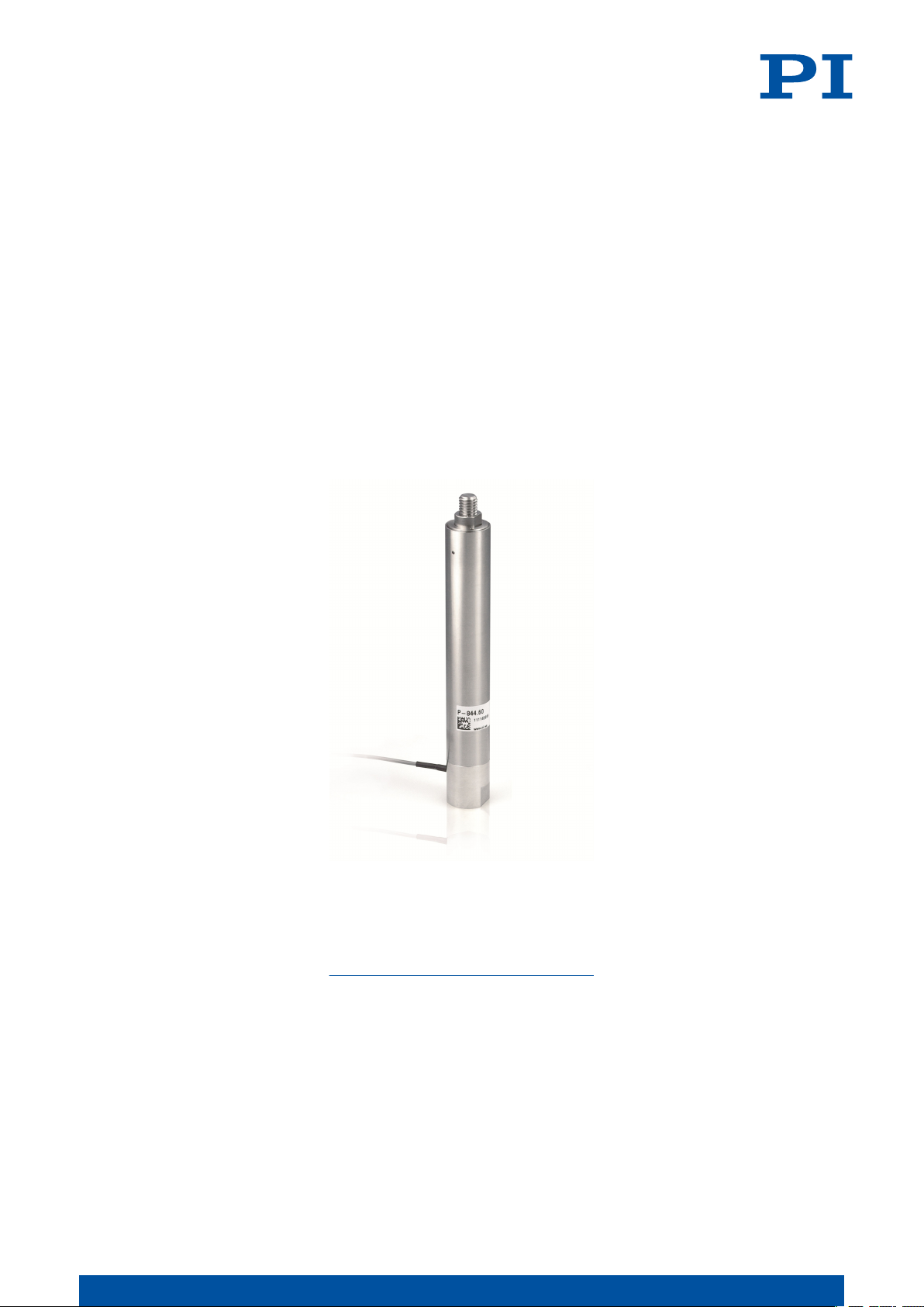
P-844 PRELOADED PIEZO ACTUATORS
M O T I O N | P O S I T I O N I N G
Page 2

CONTENTS
P844M0001EN ‒ 11/13/2018
Contents
1 Legal Information.........................................................................................................4
2 About this Document..................................................................................................5
2.1 Objective and Target Group..............................................................................5
2.2 Explanation of Symbols....................................................................................5
2.2.1 Typographic Conventions................................................................. 5
2.2.2 Symbols Used.................................................................................... 5
2.3 Figures................................................................................................................6
2.4 Downloading Manuals...................................................................................... 6
3 Safety............................................................................................................................7
3.1 Intended Use......................................................................................................7
3.2 General Safety Instructions.............................................................................. 7
3.3 Organizational Measures.................................................................................. 7
3.3.1 User Manual....................................................................................... 8
3.3.2 General Personnel Qualification.......................................................8
4 Product Description..................................................................................................... 9
4.1 Model Overview.................................................................................................9
4.2 Product Labeling................................................................................................9
4.2.1 Type Plate........................................................................................... 9
4.3 Scope of Delivery...............................................................................................9
4.4 Overview.......................................................................................................... 10
4.5 Suitable Electronics......................................................................................... 10
5 Unpacking...................................................................................................................11
6 Installation................................................................................................................. 12
6.1 Avoiding Mounting Errors.............................................................................. 12
6.2 Mounting the P-844 and Connecting to a Protective Earth Conductor........13
6.3 Fixing the Load................................................................................................ 14
6.4 Connecting the P-844.......................................................................................15
7 Startup / Operation...................................................................................................16
7.1 Determining the Operating Parameters.........................................................16
7.1.1 Calculating the Effective Mass........................................................16
7.1.2 Calculating the Maximum Operating Frequency of the Loaded
Piezo Actuator.................................................................................. 17
7.1.3 Calculating the Forces that Occur During Dynamic Operation.... 17
7.1.4 Calculating the Power Requirement for Sinusoidal Operation....17
7.2 Starting and Operating the P-844................................................................... 18
7.3 Discharging the P-844...................................................................................... 20
8 Maintenance...............................................................................................................22
8.1 Cleaning............................................................................................................22
2
M O T I O N | P O S I T I O N I N G
Page 3

CONTENTS
P844M0001EN ‒ 11/13/2018
9 Troubleshooting......................................................................................................... 23
10 Transportation............................................................................................................24
11 Customer Service Department.................................................................................25
12 Technical Data............................................................................................................ 26
12.1 Specifications...................................................................................................26
12.2 Maximum Ratings........................................................................................... 26
12.3 Ambient Conditions and Classifications........................................................27
12.4 Dimensions...................................................................................................... 29
13 Old Equipment Disposal........................................................................................... 30
14 Appendix.................................................................................................................... 31
14.1 Pin Assignment................................................................................................31
14.1.1 Voltage Connector........................................................................... 31
15 EU Declaration of Conformity...................................................................................32
3
M O T I O N | P O S I T I O N I N G
Page 4
1 LEGAL INFORMATION P844M0001EN ‒ 11/13/2018
1 Legal Information
The following company names and brands are registered trademarks of Physik Instrumente
(PI) GmbH & Co. KG:
PI®, PIC®, NanoCube®, PICMA®, PIFOC, PILine®, NEXLINE®, PiezoWalk®, PicoCube®,
PiezoMove®, PIMikroMove, NEXACT®, Picoactuator®, PInano®, NEXSHIFT®, PITOUCH®,
PIMag®, PIHera, Q-Motion®
The patents held by PI can be found in our list at http://www.physikinstrumente.com/en/
about-pi/patents.
© 2018 Physik Instrumente (PI) GmbH & Co. KG, Karlsruhe, Germany. The text, photographs,
and drawings in this manual are protected by copyright. With regard thereto, Physik
Instrumente (PI) GmbH & Co. KG reserves all rights. The use of any text, images and
drawings is permitted only in part and only when indicating the source.
Original instructions
First print: 11/13/2018
Document number: P844M0001en, CBo
Subject to change. This manual is superseded by any new release. The latest versions of the
user manuals are available for download (p. 6) at www.pi.ws.
Publisher:
Physik Instrumente (PI) GmbH & Co. KG
Auf der Roemerstrasse 1
76228 Karlsruhe
Germany
[email protected]
www.pi.de
Customer service department:
Physik Instrumente (PI) GmbH & Co. KG
Auf der Roemerstrasse 1
76228 Karlsruhe
Germany
[email protected]
www.pi.de
4
M O T I O N | P O S I T I O N I N G
Page 5
2 ABOUT THIS DOCUMENT P844M0001EN ‒ 11/13/2018
2 About this Document
2.1 Objective and Target Group
This user manual contains the information needed for the intended use of the P-844.
Basic knowledge of closed-loop systems, motion control concepts, and applicable safety
measures is assumed.
2.2 Explanation of Symbols
This chapter explains the symbols and markings used by PI in their user manuals.
2.2.1
Typographic Conventions
Symbol / Label Meaning
1.
2.
■ List items
p. 5 Cross-reference to page 5
RS-232
Start > Settings
POS?
Device S/N
5
2.2.2 Symbols Used
Symbol / Label Meaning
Action consisting of several steps whose sequential order must be observed
Labeling of an operating element on the product (example: socket of
the RS-232 interface)
Menu path in the PC software (example: to open the menu, the
and
Settings
Command line or a command from PI's General Command Set (GCS)
(example: command to get the axis position)
Parameter name (example: parameter where the serial number is stored)
Value that must be entered or selected via the PC software
menus must be clicked successively)
Start
General hazard symbol
DANGER
Dangerous situation
Failure to observe can lead to death or serious injury.
► Measures for avoiding the risk.
WARNING
Dangerous situation
Failure to observe can lead to serious injury.
► Action to take to avoid the risk.
5
M O T I O N | P O S I T I O N I N G
Page 6

2 ABOUT THIS DOCUMENT
CAUTION
Dangerous situation
Failure to observe can lead to minor injury.
► Actions to take to avoid the risk.
NOTICE
Dangerous situation
Failure to observe can lead to material damage.
► Action to take to avoid the risk.
Information
Additional information on the P-844 that can affect your application.
2.3 Figures
For better understandability, the colors, proportions and degree of detail in illustrations can
deviate from the actual circumstances. Photographic illustrations may also differ and must
not be seen as guaranteed properties.
P844M0001EN ‒ 11/13/2018
2.4 Downloading Manuals
The latest versions of the user manuals can be downloaded (p. 6) at www.pi.ws.
For products that are supplied with software (data storage device in the scope of delivery),
access to the manuals is protected by a password. Protected content is only displayed on the
website after entering the access data. You need the data storage device for the product to
get the access data.
If a manual is missing or problems occur with downloading, contact our customer service
department (p. 25).
Downloading Manuals
1. Open the website www.pi.ws.
2. If the product was shipped with a data storage device: Log into the website:
a)
Click Login.
b) Enter the login data.
The login data is in the [...]_Releasenews_[...].pdf in the Manuals directory on the
data storage device.
If necessary: Follow the link and register yourself to get the login data.
c)
Click Login or press the
3. Search for the product:
a)
Click Search.
b) Enter the product number up to the period (e.g., P-844) into the search field.
c)
Click Start search or press the
d)
If necessary: Click Load more results at the bottom of the list.
4. Click on the corresponding product in the list of search results.
5.
Click the Downloads tab.
➔
The manuals are shown under
6. Click on the desired manual and save it.
Enter key.
Enter key.
Documentation
.
6
M O T I O N | P O S I T I O N I N G
Page 7

3 SAFETY P844M0001EN ‒ 11/13/2018
3 Safety
3.1 Intended Use
The P-844 is a laboratory device as defined by DIN EN 61010-1. It is intended for indoor use
and use in an environment that is free of dirt, oil, and lubricants.
In accordance with its design, the P-844 is intended for the following applications:
■ Positioning of loads; see "Specifications" (p. 26)
■ Dynamic positioning
■ Vibration absorption
■ Force generation
Motion is along one axis.
The P-844 is not intended for applications in areas where failure would result in considerable
risks for human beings or the environment.
The intended use of the P-844 is only possible when completely mounted and connected.
The P-844 must be operated with suitable electronics (p. 10) from PI. The electronics are not
in the scope of delivery of the P-844.
The P-844 may not be used for purposes other than those stated in this user manual. The
P-844 may only be used in compliance with the technical specifications and instructions in
this user manual.
3.2 General Safety Instructions
The P-844 is built according to state-of-the-art technology and recognized safety standards.
Improper use of the P-844 may result in personal injury and/or damage to the P-844.
► Use the P-844 only for its intended purpose and if it is in perfect condition.
► Read the user manual.
► Eliminate any faults and malfunctions that are likely to affect safety immediately.
The operator is responsible for correct installation and operation of the P-844.
Temperature changes and compressive stress can induce charges in the P-844 piezo actuator.
After disconnection from the electronics, the piezo actuator can remain charged for several
hours. Touching live parts of the P-844 can result in minor injury from electric shock.
► Do not open the P-844.
If the protective earth conductor is missing or not properly connected, risk of dangerous
touch voltages on the P-844 in the event of malfunction or failure of the system. If touch
voltages exist, touching the P-844 can lead to minor injury from electric shock.
► Connect the P-844 to a protective earth conductor before startup.
► Do not remove the protective earth conductor during operation.
► If the protective earth conductor has to be temporarily removed (e.g., for modifications),
reconnect the P-844 to the protective earth conductor before restarting.
Mechanical forces can destroy the P-844.
► Avoid knocks that affect the P-844.
► Do not drop the P-844.
► Avoid torques, bending forces, and lateral forces on the tip of the P-844.
► Do not exceed the maximum permissible loads (p. 26).
3.3
7
Organizational Measures
M O T I O N | P O S I T I O N I N G
Page 8

3 SAFETY
P844M0001EN ‒ 11/13/2018
3.3.1 User Manual
► Always keep this user manual available with the P-844. The latest versions of the user
manuals can be downloaded (p. 6) at www.pi.ws.
► Add all information from the manufacturer such as supplements or technical notes to the
user manual.
► If you give the P-844 to a third party, also include this user manual as well as other
relevant information provided by the manufacturer.
► Only use the device on the basis of the complete user manual. Missing information due to
an incomplete user manual can result in minor injury and damage to equipment.
► Only install and operate the P-844 after you have read and understood this user manual.
3.3.2 General Personnel Qualification
The P-844 may only be installed, started up, operated, maintained, and cleaned by authorized
and appropriately qualified personnel.
8
M O T I O N | P O S I T I O N I N G
Page 9
4 PRODUCT DESCRIPTION P844M0001EN ‒ 11/13/2018
4 Product Description
4.1 Model Overview
Actuators without sensor
Product number Description
P-844.10 Preloaded piezo actuator, 15 µm travel range, 3000 N / 700 N
P-844.20 Preloaded piezo actuator, 30 µm travel range, 3000 N / 700 N
P-844.30 Preloaded piezo actuator, 45 µm travel range, 3000 N / 700 N
P-844.40 Preloaded piezo actuator, 60 µm travel range, 3000 N / 700 N
P-844.60 Preloaded piezo actuator, 90 µm travel range, 3000 N / 700 N
4.2 Product Labeling
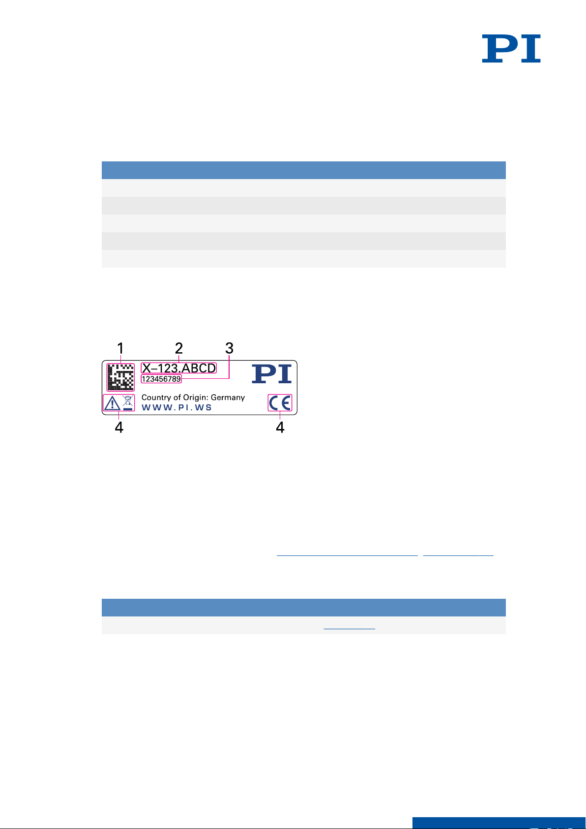
4.2.1 Type Plate
Figure 1: Type plate of the P-844
1. Data matrix code (example; contains the serial number)
2. Product number (example)
3. Serial number (example), individual for each P-844
Meaning of the position (counting from the left):
1 = internal information,
2 and 3 = year of manufacture,
4 to 9 = consecutive numbers
4. Warning and conformity symbols (old equipment disposal (p. 30), CE mark (p. 32))
4.3 Scope of Delivery
Product number Description
P-844 Actuator model according to order (p. 9)
9
M O T I O N | P O S I T I O N I N G
Page 10
4 PRODUCT DESCRIPTION
4.4 Overview
P844M0001EN ‒ 11/13/2018
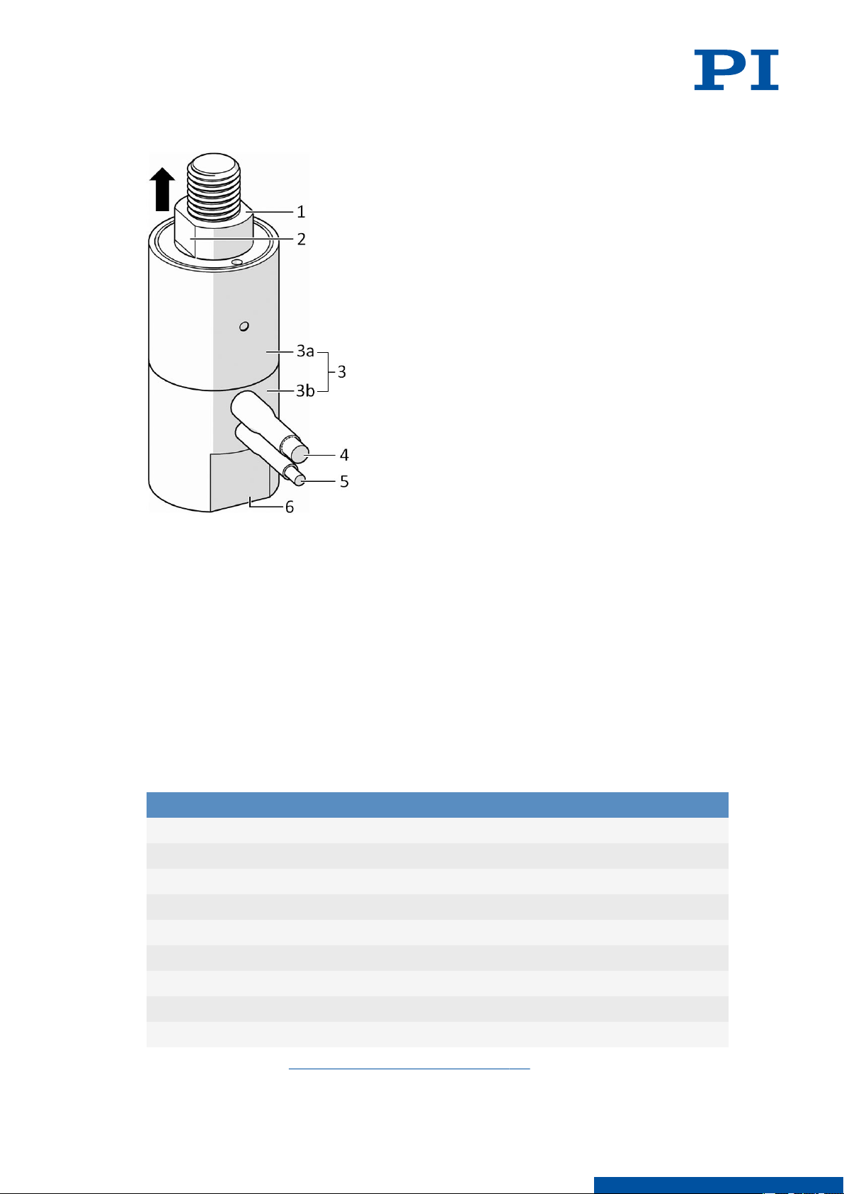
Figure 2: Example product view
1. Tip with M8 thread
2. AF10 wrench flat for open-end wrench
3. Housing, consisting of housing tube [3a] and base [3b]
4. Cable exit (sensor connector): For P-845 models only.
5. Cable exit (voltage connector)
6. AF17 wrench flat for open-end wrench
Arrow: Positive direction of motion of the tip
4.5 Suitable Electronics
The P-844 must be connected to suitable electronics that supply the necessary voltage for
operating the P-844. The following electronics are suitable for operating the P-844:
Product number
E-503 Piezo amplifier module, 3 channels, -30 to 130 V
E-505 Piezo amplifier module, 1 channel, -30 to 130 V
E-610 Piezo amplifier / servo controller, 1 channel, -30 to 130 V
E-617 High-power piezo amplifier, 1 channel, -30 to 130 V
E-621 Piezo amplifier / servo controller module, 1 channel, -30 to 130 V
Description
10
E-625 Piezo amplifier / servo controller, 1 channel, -30 to 130 V
E-663 Piezo amplifier, 3 channels, -20 to 120 V
E-709 Digital piezo controller, 1 channel, -30 to 130 V
E-831 Piezo amplifier module, 1 channel, -30 to 130 V
To order, contact our customer service department (p. 25).
M O T I O N | P O S I T I O N I N G
Page 11

5 UNPACKING
5 Unpacking
NOTICE
Destruction of the P-844 due to mechanical overload!
Mechanical forces can destroy the P-844.
► Avoid knocks that affect the P-844.
► Do not drop the P-844.
Unpacking the P-844
1. Unpack the P-844 with care.
2. Compare the contents with the scope of delivery according to the contract and the
delivery note.
3. Inspect the contents for signs of damage. If any parts are damaged or missing, contact
our customer service department (p. 25) immediately.
4. Keep all packaging materials in case the product needs to be returned.
P844M0001EN ‒ 11/13/2018
11
M O T I O N | P O S I T I O N I N G
Page 12
6 INSTALLATION
P844M0001EN ‒ 11/13/2018
6 Installation
6.1 Avoiding Mounting Errors
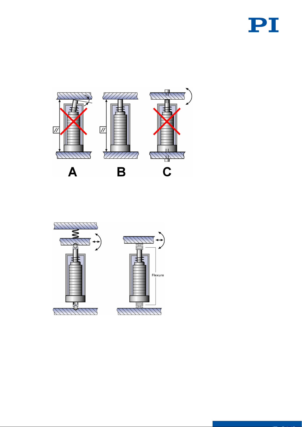
Piezo actuators may only be loaded axially. The following figures intend to help you to avoid
mounting errors.
Figure 3: Not tightly screwed at both ends and no angles
A: Wrong: Angular error at the tip
B: Right: Axial loading of the actuator
C: Wrong: The actuator is screwed tight at both ends
Figure 4: Ball tips or flexures for decoupling lateral forces and bending forces
12
M O T I O N | P O S I T I O N I N G
Page 13
6 INSTALLATION
P844M0001EN ‒ 11/13/2018
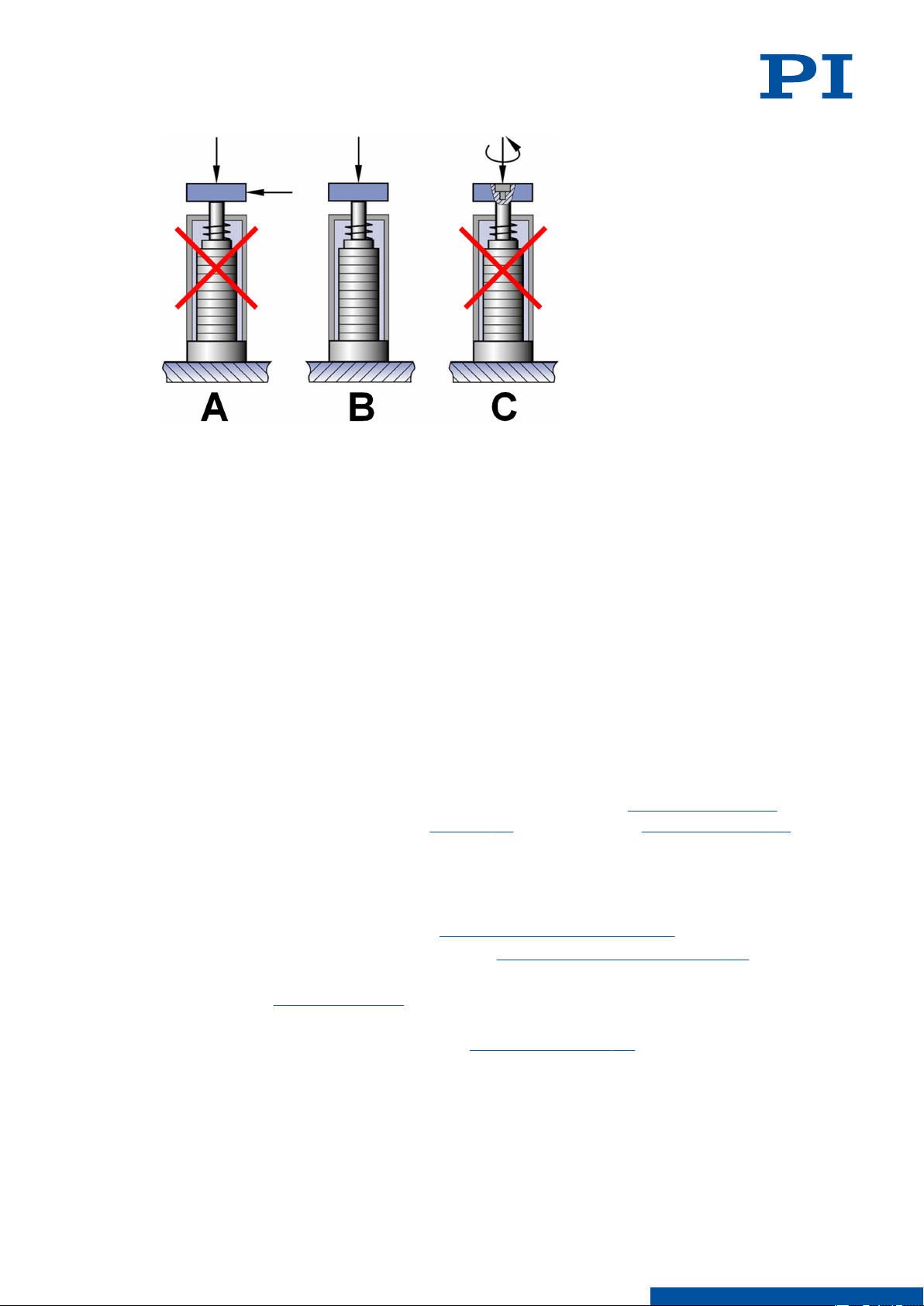
Figure 5: No lateral forces or torques
A: Wrong: Shearing force due to lateral force
B: Right: Axial loading of the actuator
C: Wrong: Torsion due to torque
6.2 Mounting the P-844 and Connecting to a Protective Earth Conductor
The protective earth connection of the P-844 is established as follows:
■ Mounting hole in the base of the P-844
■ Suitable, conductive screw
■ The underlying surface that is connected to the protective earth conductor
Pay attention to the applicable standards for connecting the protective earth conductor.
Tools and Accessories
■
Suitable protective earth conductor: Cable cross section ≥ 0.75 mm
■
Electrically conductive screw of suitable size and length (see "Dimensions" (p. 29))
■ Open-end wrench for holding the base (p. 10) of the P-844 (see "Dimensions" (p. 29) for
across flats size)
■ Suitable screwdriver
Requirements
You have read and understood the general safety instructions (p. 7).
✓
You have read and understood the section "Avoiding Mounting Errors" (p. 12).
✓
The P-844 is not connected to the electronics.
✓
The P-844 is discharged (p. 20).
✓
You have provided a suitable surface for mounting the P-844:
✓
■ The underlying surface has suitable mounting holes (p. 29).
■ The underlying surface is connected to a protective earth conductor.
■ The underlying surface is sufficiently conductive to ensure proper function of the
protective earth conductor.
You have accounted for the space required to route cables without bending and
✓
according to regulations.
2
13
M O T I O N | P O S I T I O N I N G
Page 14
6 INSTALLATION
P844M0001EN ‒ 11/13/2018
CAUTION
Risk of electric shock if the protective earth conductor is not connected!
If the protective earth conductor is missing or not properly connected, risk of dangerous
touch voltages on the P-844 in the event of malfunction or failure of the system. If touch
voltages exist, touching the P-844 can lead to minor injury from electric shock.
► Connect the P-844 to a protective earth conductor before startup.
► Do not remove the protective earth conductor during operation.
► If the protective earth conductor has to be temporarily removed (e.g., for modifications),
reconnect the P-844 to the protective earth conductor before restarting.
Information
The P-844 can heat up during operation. The heat produced during operation can affect your
application.
Mounting the P-844
1. Use an open-end wrench to hold the base of the P-844 in position.
2. Screw the P-844 onto a suitable underlying surface. For this purpose, screw into the
mounting hole in the bottom of the base (p. 29).
3. Remove the open-end wrench from the base.
6.3 Fixing the Load
Tools and Accessories
■
Nut of suitable size and length (see "Dimensions" (p. 29))
■ Open-end wrench for holding the tip (p. 10) of the P-844 (see "Dimensions" (p. 29) for
across flats size)
■ Suitable tool for tightening the nuts
Requirements
You have read and understood the general safety instructions (p. 7).
✓
You have read and understood the section "Avoiding Mounting Errors" (p. 12).
✓
The P-844 is not connected to the electronics.
✓
The P-844 is discharged (p. 20).
✓
NOTICE
Destruction of the piezo actuator due to mechanical overload!
Torques, bending and lateral forces, tensile stress, and excessive loads can destroy the piezo
actuator.
► Do not exceed the maximum permissible loads according to the specifications (p. 26).
► Avoid torques, bending forces and lateral forces on the tip of the piezo actuator.
► Avoid torques on the base when the tip is tightly clamped.
► Make sure that the center of load of the moving system is on the motion axis of the piezo
actuator.
► Use suitable structures or guide elements (e.g., ball tips or flexure guides) to avoid
uneven load distribution.
► Pay attention to the information on parallelism in the "Dimensions" section (p. 29).
► Do not screw the piezo actuator tight at both ends.
14
M O T I O N | P O S I T I O N I N G
Page 15

6 INSTALLATION
Fixing the Load
1. Use an open-end wrench to hold the tip of the P-844 in place.
2. Tighten the nut to secure the load on the tip.
3. Remove the open-end wrench from the tip.
6.4 Connecting the P-844
Tools and Accessories
■ If necessary: Suitable cable set
■ If necessary: Suitable screwdriver for the locking screws of the connectors.
Requirements
You have read and understood the general safety instructions (p. 7).
✓
You have read and understood the user manual for the electronics used.
✓
You have installed the electronics properly.
✓
The electronics are switched off.
✓
P844M0001EN ‒ 11/13/2018
NOTICE
Damage due to incorrect connection of the P-844!
Connecting unsuitable electronics or a wrong cable can damage the P-844 or the electronics.
► Connect the P-844 only to suitable electronics from PI (p. 10).
► Use cables from PI only to connect the P-844 to the electronics.
Connecting the P-844
1. Connect the P-844's voltage plug to the voltage socket on the electronics.
15
M O T I O N | P O S I T I O N I N G
Page 16
7 STARTUP / OPERATION
P844M0001EN ‒ 11/13/2018
7 Startup / Operation
7.1 Determining the Operating Parameters
Limiting factors for the operation of the piezo actuator:
■ Resonant frequency:
The operating frequency may not exceed one third of the resonant frequency of the
loaded piezo actuator. See "Calculating the Maximum Operating Frequency of the Loaded
Piezo Actuator" (p. 17).
■ Maximum push/pull force capacity (p. 26):
The mass of the load to be moved and the operating frequency of the piezo actuator must
be selected so that any dynamic forces generated during operation do not exceed the
maximum push/pull force capacity of the piezo actuator. See "Calculating the Forces that
Occur During Dynamic Operation" (p. 17).
■ Maximum permissible operating temperature of the piezo actuator (p. 26):
The greater the operating frequency, the operating voltage (peak-to-peak), and the
capacitance of the piezo actuator, the greater the thermal power generated in the piezo
actuator. The operating frequency, operating voltage and operating time must be selected
so that the maximum permissible operating temperature of the piezo actuator is not
exceeded. For the maximum permissible operating frequency without cooling, see
column B of the table in
"Maximum Ratings" (p. 26).
7.1.1
Peak and average output current of the electronics:
The electronics used (p. 10) for operating the P-844 must meet the following requirements:
■ The electronics can provide the required current. See "Calculating the Power Requirement
for Sinusoidal Operation" (p. 17).
■ The output current of the electronics does not exceed the maximum power consumption
of the piezo actuator. See "Maximum Ratings" (p. 26).
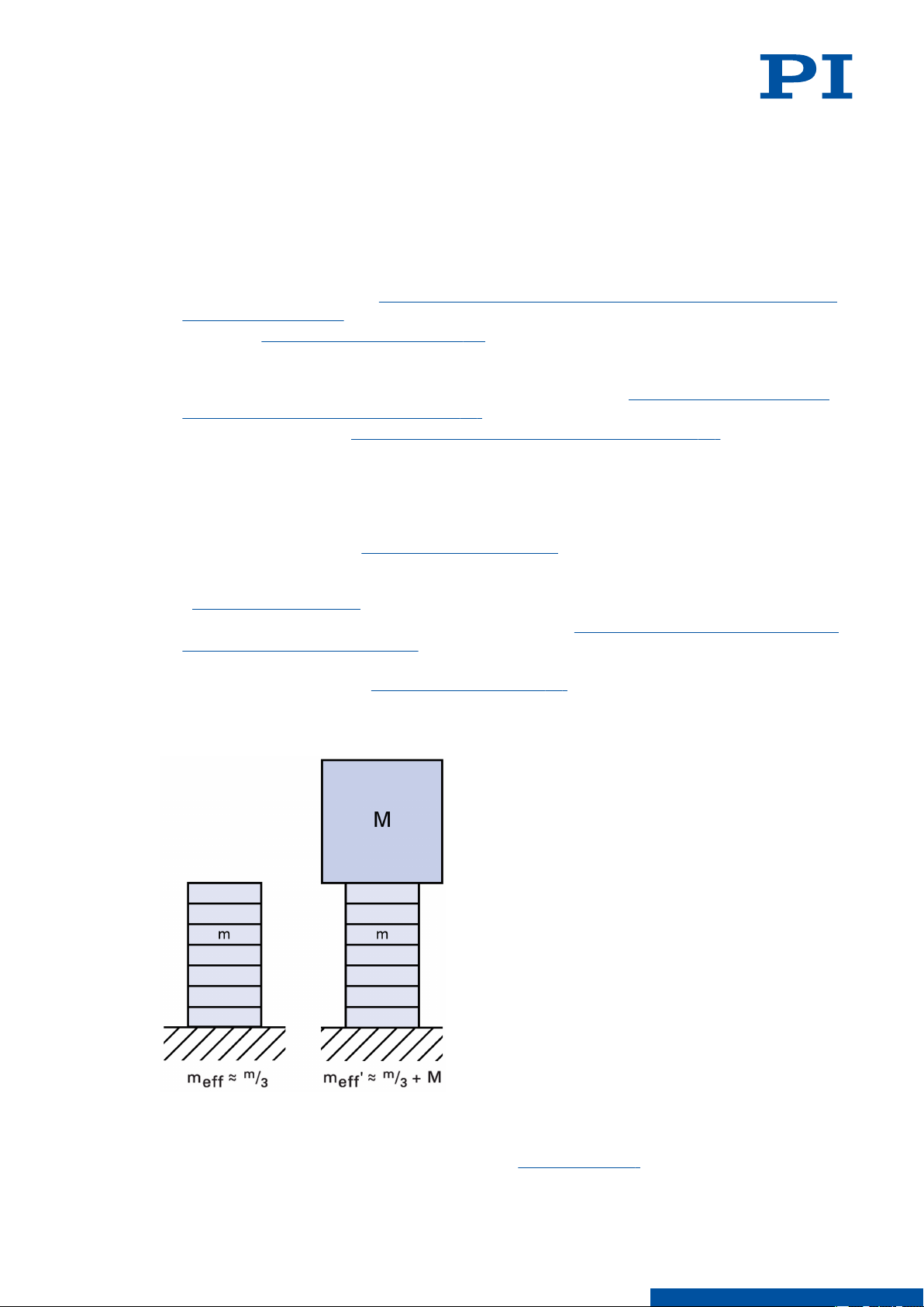
Calculating the Effective Mass
16
Figure 6: Calculation of the effective mass of a unilaterally clamped piezo stack actuator
without load (left) and with additional load (right).
1. Find the mass m of your piezo actuator in the data table (p. 26).
2. Determine the additional load M.
M O T I O N | P O S I T I O N I N G
Page 17
7 STARTUP / OPERATION
3. Calculate the effective mass meff of the unloaded piezo actuator and meff' of the loaded
piezo actuator using the formulas in the figure above.
P844M0001EN ‒ 11/13/2018
7.1.2 Calculating the Maximum Operating Frequency of the Loaded Piezo Actuator
Information
In the following calculation, the maximum permissible operating temperature of the piezo
actuator is not taken into account. During operation without cooling, the maximum
operating temperature may already be exceeded when the operating frequency is still below
the limit value calculated in the following.
► For the maximum permissible operating frequency without cooling, see column B of the
table in "Maximum Ratings" (p. 26).
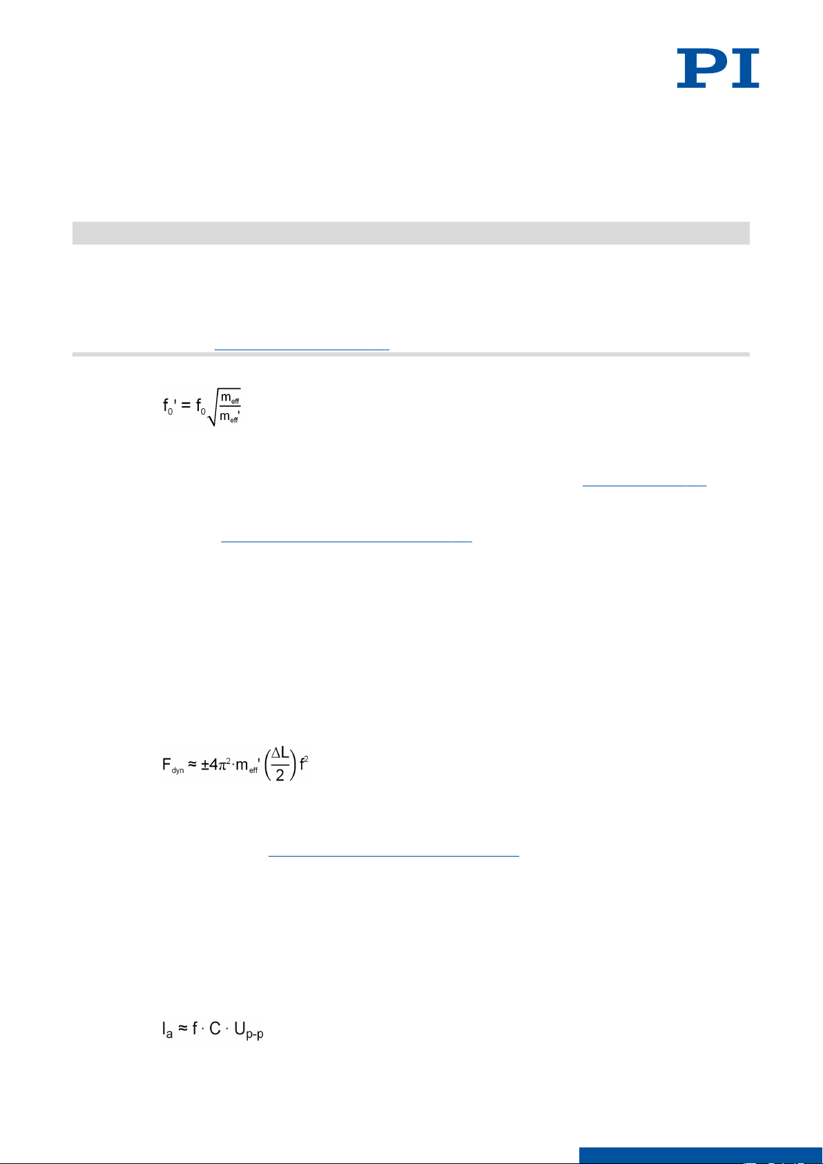
1. Calculate the resonant frequency of the loaded piezo actuator with the following formula:
Variables:
f0' = Resonant frequency of the loaded piezo actuator [Hz]
f0 = Resonant frequency of the unloaded piezo actuator [Hz]; see "Data Table" (p. 26).
meff = Effective mass; approx. 1/3 of the mass of the piezo actuator [kg]
meff' = Effective mass meff + additional load M [kg]
See also "Calculating the Effective Mass" (p. 16).
2. Calculate the maximum operating frequency of the loaded piezo actuator with the
following formula:
fmax = f0'/3
Variables:
fmax = Maximum operating frequency of the loaded piezo actuator [Hz]
f0' = Resonant frequency of the loaded piezo actuator [Hz]
7.1.3
7.1.4
Calculating the Forces that Occur During Dynamic Operation
1. Use the following formula to calculate the dynamic forces acting on the piezo actuator
during sinusoidal operation with the frequency f:
Variables:
Fdyn = Dynamic force [N]
meff' = Effective mass meff (approx. 1/3 of the mass of the piezo actuator) + additional load
M [kg], see also "Calculating the Effective Mass" (p. 16)
ΔL = Displacement in the application (peak-to-peak) [m]
f = Frequency [Hz]
Example: The dynamic forces are approximately ±40 N at 1000 Hz, 2 µm displacement
(peak-peak) and 1 kg effective mass.
Calculating the Power Requirement for Sinusoidal Operation
1. Calculate the average current requirement for sinusoidal operation using the following
formula:
17
M O T I O N | P O S I T I O N I N G
Page 18
7 STARTUP / OPERATION P844M0001EN ‒ 11/13/2018
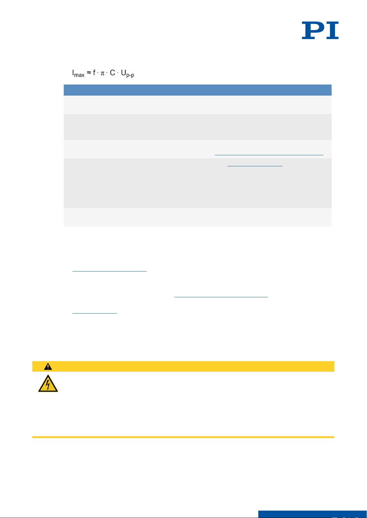
2. Calculate the peak current requirement for sinusoidal operation using the following
formula:
Variable Description Notes
Ia Required average current of the ampli-
fier (source / sink) [A]
Imax Required peak current of the amplifier
(source / sink) [A]
f Operating frequency [Hz] Details on the operating frequency see
C Capacitance of the piezo actuator [F (=
As/V)]
Up-p Operating voltage (peak-to-peak) [V] Voltage difference between positive
7.2 Starting and Operating the P-844
Tools and Accessories
■
Electronics from PI (p. 10)
It is essential that the power adapter
can supply enough current.
The provided peak current depends on
the internal storage capacity of the amplifier.
"Overview of Limiting Factors" (p. 16).
See "Data Table" (p. 26) for the small-
signal capacitance of the piezo actuator.
For large-signal conditions, a safety
factor of 70 % should be added to the
small-signal capacitance.
and negative peak voltage
Requirements
You have read and understood the general safety instructions (p. 7).
✓
For startup with a load or in a multi-axis system: You have installed the P-844
✓
properly (p. 12).
You have read and understood the user manual for the electronics used.
✓
If a digital controller is used: You have read and understood the manual for the PC
✓
software used.
The electronics and if required, the PC software, have been installed (see the user manual
✓
for the electronics).
CAUTION
Risk of electric shock if the protective earth conductor is not connected!
If the protective earth conductor is missing or not properly connected, risk of dangerous
touch voltages on the P-844 in the event of malfunction or failure of the system. If touch
voltages exist, touching the P-844 can lead to minor injury from electric shock.
► Connect the P-844 to a protective earth conductor before startup.
► Do not remove the protective earth conductor during operation.
► If the protective earth conductor has to be temporarily removed (e.g., for modifications),
reconnect the P-844 to the protective earth conductor before restarting.
18
M O T I O N | P O S I T I O N I N G
Page 19
7 STARTUP / OPERATION P844M0001EN ‒ 11/13/2018
CAUTION
Burning due to hot surface!
The surface of the P-844 and the surroundings can heat up during operation. Touching the
P-844 and surrounding parts can result in minor injuries from burning.
► Make sure that the hot P-844 and the surrounding parts cannot be touched.
NOTICE
Destruction of the piezo actuator due to electric flashovers
Using the P-844 in environments that increase the electrical conductivity can lead to the
destruction of the piezo actuator by electric flashovers. Electric flashovers can be caused by
moisture, high humidity, liquids, and conductive materials (e.g., metal dust). In addition,
electric flashovers can also occur in certain air pressure ranges due to the increased
conductivity of the air.
► Avoid operating the P-844 in environments that can increase the electrical conductivity.
► Operate the P-844 only within the permissible ambient condition and
classifications (p. 27).
NOTICE
Destruction of the piezo actuator due to dynamic forces!
Dynamic forces can be generated during dynamic operation that cancel out the preload of
the piezo actuator. Operating without a preload can destroy the actuator.
► Do not exceed the maximum push/pull capacity according to the specifications (p. 26).
► Pay attention to the notes in "Determining the Operating Parameters" (p. 16).
NOTICE
Destruction of the piezo actuator due to excessive operating frequencies!
Excessive operating frequencies can destroy the piezo actuator.
► Select the operating frequency so that the following conditions are met:
■ The maximum operating frequency may not exceed one third of the resonant frequency
(see "Data Table" (p. 26) for the resonant frequency of the unloaded piezo actuator and
see "Calculating the Maximum Operating Frequency of the Loaded Piezo Actuator" (p. 17)
for the resonant frequency of the loaded piezo actuator).
■ Any dynamic forces generated during operation do not exceed the maximum push/pull
force of the piezo actuator (see "Calculating the Forces that Occur During Dynamic
Operation" (p. 17) and "Specifications" (p. 26)).
NOTICE
Reduced lifetime of the piezo actuator due to permanently high voltage!
The permanent application of a high voltage to piezo actuators leads to a considerable
reduction in the lifetime of the piezo ceramic.
► When the P-844 is not being used (e.g., to ensure temperature stability of the electronics),
discharge (p. 20) it.
► If possible, limit the maximum operating voltage during continuous operation.
NOTICE
Operating voltage excessively high or incorrectly connected!
Operating voltages that are too high or incorrectly connected can cause damage to the P-844.
► Pay attention to the operating voltage range (p. 26), which is specified for the P-844.
► Pay attention to correct pin assignment (p. 31).
19
M O T I O N | P O S I T I O N I N G
Page 20
7 STARTUP / OPERATION
NOTICE
Damage after reconnecting due to a charged P-844!
The P-844 can remain charged when the connecting cable is pulled out of the electronics
during operation. Reconnecting a charged P-844 to electronics during operation can cause a
mechanical impulse that will damage the P-844.
► Do not pull the connecting cable of the P-844 out of the electronics during operation.
► If the connecting cable of the P-844 is accidentally pulled out of the electronics during
operation: Switch off the electronics before you reconnect the P-844.
NOTICE
Destruction of the piezo actuator due to overheating!
Overheating can destroy the piezo actuator.
► Adjust the operating voltage, operating frequency and/or operating time so that the
maximum operating temperature (p. 26) of the piezo actuator is not exceeded; see
"Maximum Ratings" (p. 26) and "Determining the Operating Parameters" (p. 16).
NOTICE
Uncontrolled oscillation!
Oscillation can cause irreparable damage to the P-844. Oscillation is indicated by a humming
noise and can be caused by the following:
■ A change in the load and/or dynamics requires the operating parameters to be adjusted.
■ The P-844 is operated near to its resonant frequency.
► If you notice oscillation, stop the P-844 immediately.
P844M0001EN ‒ 11/13/2018
Starting and Operating the P-844
1. Start up the electronics (see the user manual for the electronics).
2. Configure the electronics for the P-844 during startup. If you are using a digital controller
from PI, run the PC software and select the entry in the positioner database that matches
the P-844 exactly.
3. Start a few motion cycles for testing purposes (see the user manual for the electronics).
7.3 Discharging the P-844
The P-844 must be discharged in the following cases:
■ When the P-844 is not in use but the electronics remain switched on to ensure
temperature stability
■ If the P-844 is accidentally disconnected from the electronics during operation
■ Before disassembling (e.g., before cleaning and transporting the P-844) as well as for
modifications
Requirements
You have read and understood the general safety instructions (p. 7).
✓
Tools and Accessories
■
Electronics from PI (p. 10)
20
Discharging a P-844 Connected to the Electronics
1. Set the piezo voltage to 0 V on the electronics.
M O T I O N | P O S I T I O N I N G
Page 21

7 STARTUP / OPERATION P844M0001EN ‒ 11/13/2018
Discharging a P-844 not Connected to the Electronics
1. Insert the P-844's voltage connector into the switched-off electronics from PI and maintain
the connection for a few seconds.
21
M O T I O N | P O S I T I O N I N G
Page 22
8 MAINTENANCE
8 Maintenance
The P-844 is maintenance-free.
8.1 Cleaning
Requirements
You have disconnected the P-844 from the electronics.
✓
The P-844 is discharged (p. 20).
✓
Auxiliary Materials Required
■ Soft, lint-free cloth
■ Mild cleaning agent or disinfectant
If you have any questions on the auxiliary materials recommended for the P-844, contact our
customer service department (p. 25).
NOTICE
Short-circuiting due to cleaning fluid penetrating the housing!
Cleaning fluid penetrating the P-844’s housing can short-circuit the actuator and drive
electronics.
► Disconnect the P-844 from the electronics before cleaning.
► Prevent cleaning fluid from penetrating the P-844‘s housing.
P844M0001EN ‒ 11/13/2018
NOTICE
Damage due to unsuitable cleaning agents!
Some cleaning agents may cause damage to the P-844.
► Use mild cleaning agents or disinfectants only.
NOTICE
Damage from ultrasonic cleaning!
Ultrasonic cleaning can damage the P-844.
► Do not do any ultrasonic cleaning.
Cleaning the P-844
1. Dampen the cloth with the cleaning agent or disinfectant.
2. Carefully wipe the surfaces of the P-844.
22
M O T I O N | P O S I T I O N I N G
Page 23

9 TROUBLESHOOTING P844M0001EN ‒ 11/13/2018
9 Troubleshooting
No or limited motion
Cable not connected correctly
Excessive load
► Check the cable connecons.
► Do not exceed the maximum push/pull capacity
according to the specicaons (p. 26).
Piezo actuator is depolarized due to overheating
Defective actuator
► Contact our customer service depart‐
ment (p. 25).
► If possible, replace the defecve actuator with
another actuator and test the new combinaon.
The piezo actuator starts oscillating or positions inaccurately
Operating parameters wrongly set because
for example, the load was changed
► Switch o the electronics immediately.
► Check the sengs of the operang parameters
(see the user manual for the electronics).
► If necessary, correct the sengs for the operat‐
ing parameters.
Operating with an excessively high frequency
► Operate the piezo actuator at a maximum of one
third of the resonant frequency (see "Data Ta‐
ble" (p. 26) for resonant frequency of the un‐
loaded piezo actuator, see "Calculang the Maxi‐
mum Operang Frequency of the Loaded Piezo
Actuator" (p. 17) for resonant frequency of the
loaded piezo actuator).
23
M O T I O N | P O S I T I O N I N G
Page 24

10 TRANSPORTATION P844M0001EN ‒ 11/13/2018
10 Transportation
Preparing the P-844 for Transportation
1. Pay attention to the ambient conditions and classifications (p. 27).
2. Pack the P-844 in the original packaging.
3. If the P-844 is to be sent, use a stable outer box.
24
M O T I O N | P O S I T I O N I N G
Page 25

11 CUSTOMER SERVICE DEPARTMENT
P844M0001EN ‒ 11/13/2018
11 Customer Service Department
For enquiries and orders, contact your PI representative or send us an email.
If you have any questions concerning your system, provide the following information:
■ Product and serial numbers of all products in the system
■ Firmware version of the controller (if applicable)
■ Version of the driver or the software (if applicable)
■ Operating system on the PC (if applicable)
If possible: Take photographs or make videos of your system that can be sent to our
customer service department if requested.
Customer service address:
Physik Instrumente (PI) GmbH & Co. KG
Auf der Roemerstrasse 1
76228 Karlsruhe
Germany
[email protected]
www.pi.de
25
M O T I O N | P O S I T I O N I N G
Page 26

12 TECHNICAL DATA
12 Technical Data
12.1 Specifications
P-844.10 P-844.20 P-844.30 P-844.40 P-844.60 Unit Toler-
P844M0001EN ‒ 11/13/2018
ance
Travel range at 0 to
100 V
Resolution* 0.15 0.3 0.45 0.6 0.9 nm
Static large signal
stiffness**
Push force capacity 3000 3000 3000 3000 3000 N
Pull force capacity 700 700 700 700 700 N
Torque on tip 1 1 1 1 1 Nm max.
Electrical capacitance 6 12 18 24 36 µF ±20 %
Resonant frequency f0
(no load)
Operating temperature range
Mass without cable 84 108 132 156 204 g ±5 %
Length L 47 65 83 101 137 mm
Recommended electronics
15 30 45 60 90 µm ±20 %
225 107 75 57 38 N/µm ±20 %
16 12 9 7.5 5.5 kHz ±20 %
-40 to 80 -40 to 80 -40 to 80 -40 to 80 -40 to 80 °C
E-503,
E-505,
E-610,
E-617,
E-621,
E-625,
E-663,
E-709,
E-831
E-503,
E-505,
E-610,
E-617,
E-621,
E-625,
E-663,
E-709,
E-831
E-503,
E-505,
E-610,
E-617,
E-621,
E-625,
E-663,
E-709,
E-831
E-503,
E-505,
E-610,
E-617,
E-621,
E-625,
E-663,
E-709,
E-831
E-503,
E-505,
E-610,
E-617,
E-621,
E-625,
E-663,
E-709,
E-831
26
12.2
* The resolution of the system is only limited by the noise of the amplifier and measuring
technology because PI piezo actuators are free of friction.
** Dynamic small-signal stiffness is approx. 30 % higher.
Voltage connector: LEMO FFA.00.250. RG 178 coaxial cable, 1 m.
Housing / tip material: Stainless steel.
Vacuum versions to 10-6 hPa are available under the order number P-844.x0V.
All specifications based on room temperature (22 °C ±3 °C).
Specifications for vacuum versions can differ.
Maximum Ratings
P-844 piezo actuators are designed for the operating data specified in the table below.
Additional information on the maximum ratings table
■
Maximum operating frequency without load, without considering thermal aspects,
column A:
M O T I O N | P O S I T I O N I N G
Page 27

12 TECHNICAL DATA
The value corresponds to one third of the resonant frequency of the unloaded piezo
actuator. For further restrictions, see "Overview of Limiting Factors" (p. 16).
■ Maximum operating frequency without load, considering thermal aspects, column B:
In order to prevent the maximum permissible operating temperature from being
exceeded, the operating frequency of the unloaded, uncooled piezo actuator must not
exceed the specified frequency when the operating voltage is 100 V peak-to-peak. In the
case of smaller amplitudes of the operating voltage and/or the use of cooling measures,
higher operating frequencies are possible. For further restrictions, see "Overview of
Limiting Factors" (p. 16).
■ Maximum power consumption:
The value corresponds to the power consumption of the unloaded, uncooled piezo
actuator that is operated at a voltage of 100 V peak-to-peak with the operating frequency
from column B of this table.
P844M0001EN ‒ 11/13/2018
Piezo actuator*
Maximum
operating
Maximum operating frequency
without load
voltage
range
A:
Without considering thermal
aspects
P-84x.10 0 to 100 V 5333 Hz 55 Hz 5.7 W
P-84x.20 0 to 100 V 4000 Hz 48 Hz 11.4 W
P-84x.30 0 to 100 V 3000 Hz 45 Hz 17.1 W
P-84x.40 0 to 100 V 2500 Hz 42 Hz 22.8 W
P-84x.60 0 to 100 V 1833 Hz 39 Hz 34.2 W
* The letter x in the product number of the piezo actuator stands for "4" or "5".
12.3 Ambient Conditions and Classifications
B:
Considering
thermal aspects
Maximum power consumption
Considering
thermal aspects
27
The following ambient conditions and classifications for the P-844 must be observed:
M O T I O N | P O S I T I O N I N G
Page 28

12 TECHNICAL DATA P844M0001EN ‒ 11/13/2018
Area of application For indoor use only
Maximum altitude 2000 m above msl
Air pressure 1100 hPa to 100 hPa
Relative humidity Highest relative humidity 80 % for temperatures up to 31 °C
Decreasing linearly to 50 % relative humidity at 40 °C
Storage temperature –20 °C to 80 °C
Transport temperature –20 °C to 80 °C
Overvoltage category II
Protection class I
Degree of pollution 1
Degree of protection according to IEC 60529
IP20
28
M O T I O N | P O S I T I O N I N G
Page 29
12 TECHNICAL DATA
12.4 Dimensions
P844M0001EN ‒ 11/13/2018
29
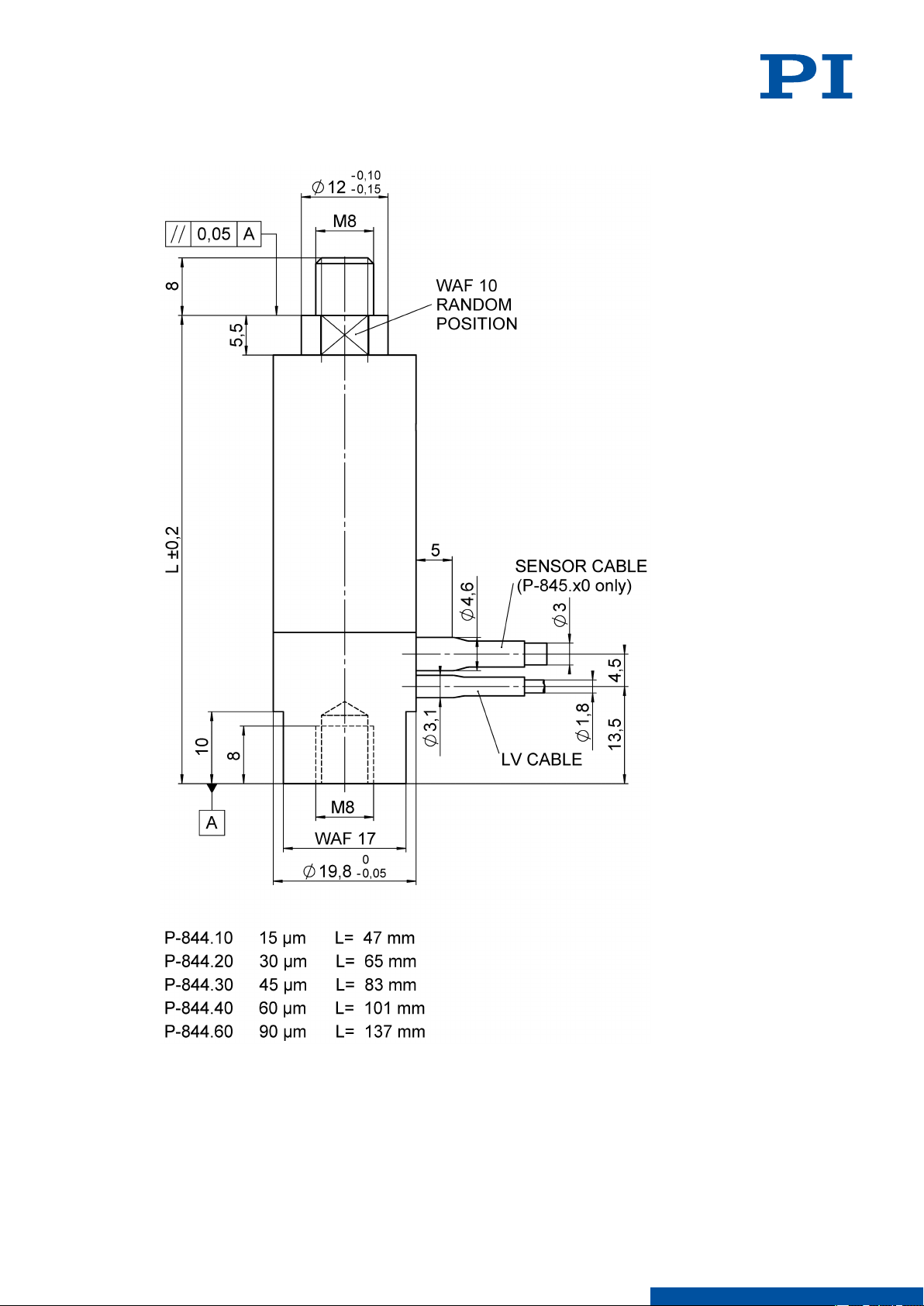
Figure 7: Dimensions of the P-844
Dimensions in mm. Note that the decimal places are separated by a comma in the drawings.
The exact position of the wrench flats on the tip is not defined, i.e., the tip and base can be
offset from each other at any angle with respect to the wrench flats.
M O T I O N | P O S I T I O N I N G
Page 30
13 OLD EQUIPMENT DISPOSAL
P844M0001EN ‒ 11/13/2018
13 Old Equipment Disposal
In accordance with EU law, electrical and electronic equipment may not be disposed of in EU
member states via the municipal residual waste.
Dispose of your old equipment according to international, national, and local rules and
regulations.
In order to fulfil the responsibility as the product manufacturer, PI undertakes
environmentally correct disposal of all PI equipment free of charge, if it was made available
to the market after August 13, 2005.
Any old PI equipment can be sent free of charge to the following address:
Physik Instrumente (PI) GmbH & Co. KG
Auf der Roemerstrasse 1
76228 Karlsruhe
Germany
[email protected]
www.pi.de
30
M O T I O N | P O S I T I O N I N G
Page 31
14 APPENDIX P844M0001EN ‒ 11/13/2018
14 Appendix
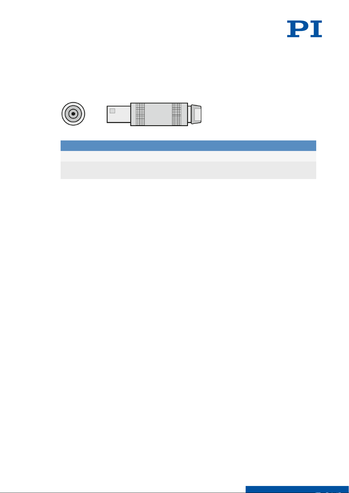
14.1 Pin Assignment
14.1.1 Voltage Connector
Figure 8: Voltage connector: LEMO FFA.00.250.CTAC22
Pin Signal Function
Inner contact Input Piezo voltage 0 to 100 V
Connector shell /
cable shield
Input Piezo voltage ground
31
M O T I O N | P O S I T I O N I N G
Page 32

15 EU DECLARATION OF CONFORMITY
P844M0001EN ‒ 11/13/2018
15 EU Declaration of Conformity
An EU Declaration of Conformity was issued for the P-844 in accordance with the following
European directives:
■ Low Voltage Directive
■ EMC Directive
■ RoHS Directive
The standards applied for certifying conformity are listed below.
■ Safety (Low Voltage Directive): EN 61010-1
■ EMC: EN 61326-1
■ RoHS: EN 50581
32
M O T I O N | P O S I T I O N I N G
 Loading...