

Page 1
Physik Instrumente (PI) GmbH & Co. KG, Auf der Roemerstrasse 1, 76228 Karlsruhe, Germany
PZ234E
P
User Manual
Version: 1.1.0
Date: 27.08.2018
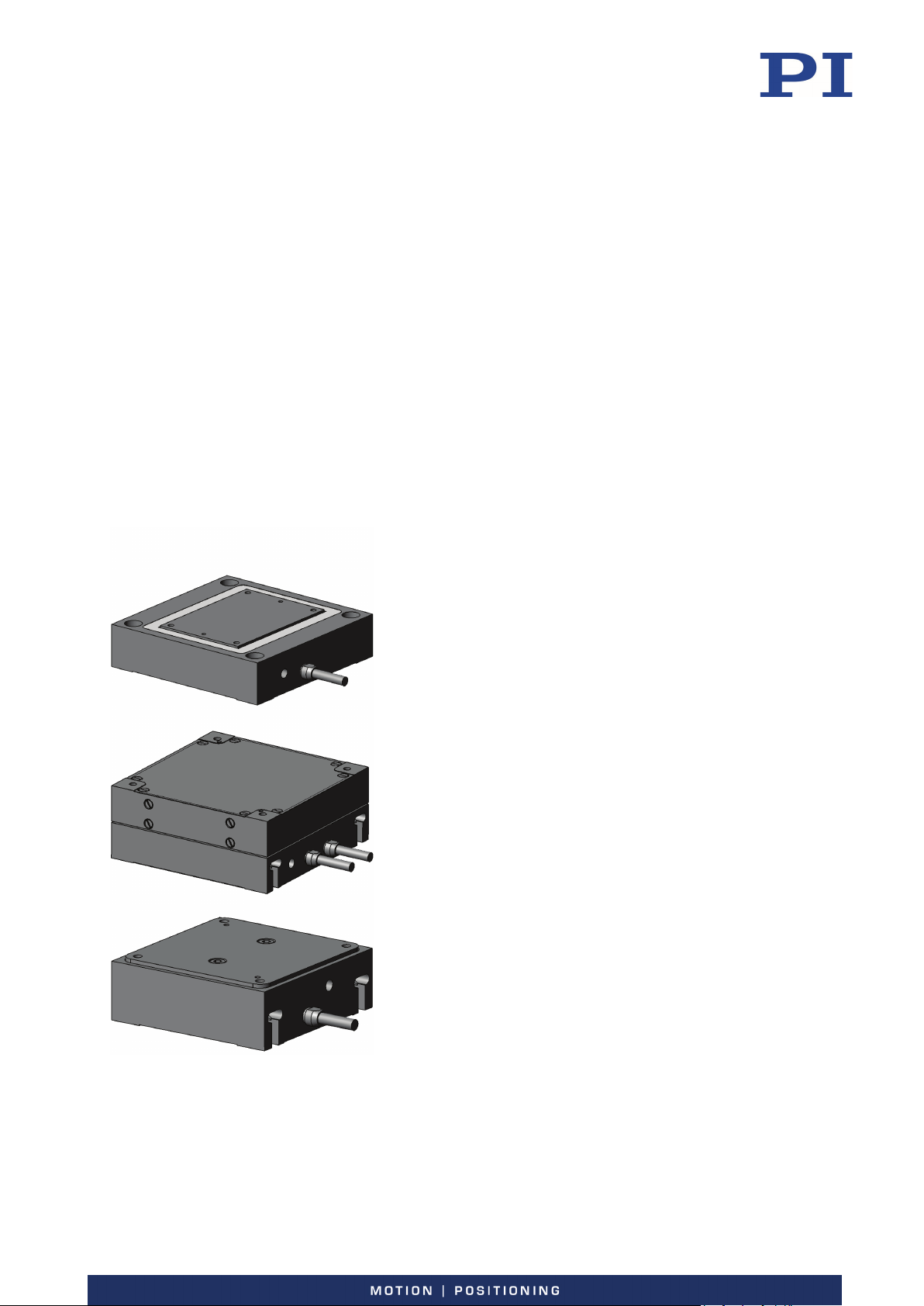
This document describes the following products:
-62x Positioning Systems
P-620, P-621, P-622, P-625, P-628, P-629
PIHera piezo linear stage
P-620.1CD/.1CL/.10L
P-621.1CD/.1CL/.10L/.1U
P-622.1CD/.1CL/.10L/.1U
P-625.1CD/.1CL/.10L
P-628.1CD/.1CL/.10L
P-629.1CD/.1CL/.10L
P-620, P-621, P-622, P-625, P-628, P-629
PIHera piezo XY stage
P-620.2CD/.2CL/.20L
P-621.2CD/.2CL/.20L/.2U
P-622.2CD/.2CL/.20L/.2U
P-625.2CD/.2CL/.20L
P-628.2CD/.2CL/.20L
P-629.2CD/.2CL/.20L
P-620, P-621, P-622
PIHera precision Z stage
P-620.ZCD/.ZCL/.Z0L
P-621.ZCD/.ZCL/.Z0L
P-622.ZCD/.ZCL/.Z0L
.1CD/.2CD/.ZCD
= with Sub-D connector 7W2
.1U/.2U
= with Sub-D connector 5W1 (f)
.1CL/.2CL/.ZCL/.10L/.20L/.Z0L
= with LEMO connector
Phone +49 721 4846-0, Fax +49 721 4846-1019, Email [email protected], www.pi.ws
Page 2

The following company names and brands are registered trademarks of Physik Instrumente (PI) GmbH & Co.
KG:
PI®, NanoCube®, PICMA®, PILine®, NEXLINE®, PiezoWalk®, NEXACT®, Picoactuator®, PInano®, PIMag®,
Q-Motion®
The patents held by PI are found in our patent list:
http://www.physikinstrumente.com/en/about-pi/patents
© 2018 Physik Instrumente (PI) GmbH & Co. KG, Karlsruhe, Germany. The text, photographs and drawings in
this manual are protected by copyright. With regard thereto, Physik Instrumente (PI) GmbH & Co. KG retains
all the rights. The use of any text, images and drawings is permitted only in part and only when indicating the
source.
Original instructions
First printing: 27.08.2018
Document number: PZ234E, CBo, Version 1.1.0
Subject to change without notice. This manual is superseded by any new release. The latest release is
available for download (p. 3) on our website.
Page 3

Contents
1 About this Document 1
1.1 Objective and Target Audience of this User Manual.................................................. 1
1.2 Symbols and Typographic Conventions...................................................................... 1
1.3 Definition of Terms ..................................................................................................... 2
1.4 Figures ........................................................................................................................ 2
1.5 Other Applicable Documents ..................................................................................... 3
1.6 Downloading Manuals ................................................................................................ 3
2 Safety 5
2.1 Intended Use .............................................................................................................. 5
2.2 General Safety Instructions ........................................................................................ 5
2.3 Organizational Measures ............................................................................................ 7
3 Product Description 9
3.1 Model Overview ......................................................................................................... 9
3.2 Product View ............................................................................................................ 12
3.3 Product Labeling ....................................................................................................... 13
3.4 Scope of Delivery ...................................................................................................... 14
3.5 Suitable Electronics .................................................................................................. 15
3.6 Accessories ............................................................................................................... 15
3.7 Technical Features .................................................................................................... 16
3.7.1 PICMA® Piezo Actuators .............................................................................. 16
3.7.2 Flexure Guides ............................................................................................. 16
3.7.3 Capacitive Sensors ....................................................................................... 17
3.7.4 ID Chip (Models with Sub-D 7W2 Connector Only) ..................................... 17
4 Unpacking 19
5 Installation 21
5.1 General Notes on Installation ................................................................................... 21
5.2 Mounting the Positioner and Affixing the Load ....................................................... 22
5.3 Connecting the P-62x to the Protective Earth Conductor ........................................ 25
5.4 Connecting the Vacuum Version to the Electronics ................................................. 29
6 Startup and Operation 31
6.1 General Notes on Startup and Operation ................................................................ 31
6.2 Operating the P-62x ................................................................................................. 33
6.3 Discharging the P-62x ............................................................................................... 33
Page 4

7 Maintenance 35
7.1 General Notes on Maintenance ............................................................................... 35
7.2 Cleaning the P-62x .................................................................................................... 35
8 Troubleshooting 37
9 Customer Service 39
10 Technical Data 41
10.1 Specifications ............................................................................................................ 41
10.1.1 Data Table .................................................................................................... 41
10.1.2 Materials Used for Vacuum-Compatible Models ........................................ 45
10.1.3 Maximum Ratings ........................................................................................ 45
10.1.4 Ambient Conditions and Classifications ...................................................... 46
10.2 Dimensions ............................................................................................................... 47
10.3 Torque for Stainless Steel Screws (A2-70) ................................................................ 50
10.4 Pin Assignment ......................................................................................................... 50
11 Old Equipment Disposal 53
12 EU Declaration of Conformity 55
Page 5
1 About this Document
Downloading Manuals ................................................................................................................... 3
1
About this Document
In this Chapter
Objective and Target Audience of this User Manual ..................................................................... 1
Symbols and Typographic Conventions ......................................................................................... 1
Definition of Terms ........................................................................................................................ 2
Figures ............................................................................................................................................ 2
Other Applicable Documents ......................................................................................................... 3
1.1 Objective and Target Audience of this User Manual
This user manual contains the necessary information for the intended use of the P-62x (x stands
for the different models (p. 9)).
Basic knowledge of control technology, drive technologies and suitable safety measures is
assumed.
The latest versions of the user manuals are available for download (p. 3) on our website.
1.2 Symbols and Typographic Conventions
The following symbols and typographic conventions are used in this user manual:
CAUTION
Dangerous situation
If not avoided, the dangerous situation will result in minor injury.
Actions to take to avoid the situation.
NOTICE
Dangerous situation
If not avoided, the dangerous situation will result in damage to the equipment.
Actions to take to avoid the situation.
P-62x Positioning Systems PZ234E Version: 1.1.0 1
INFORMATION
Information for easier handling, tricks, tips, etc.
Page 6
1 About this Document
List item
Piezo controller
Electronics with sensor evaluation for closed-loop operating of
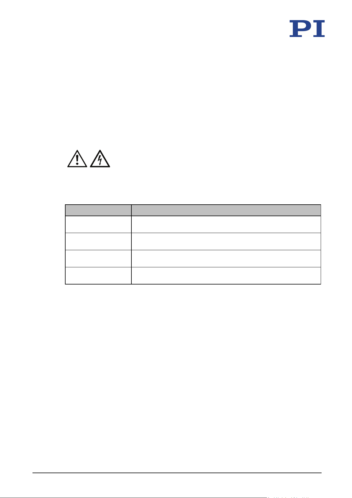
Symbol/Label Meaning
1.
2.
Action consisting of one or several steps whose sequential order
p. 5 Cross-reference to page 5
RS-232 Labeling of an operating element on the product (example:
1.3 Definition of Terms
Term Explanation
Positioner Electrically driven mechanics (here: P-62x) with one or more motion
axes
Electronics Piezo amplifier or piezo controller that supplies the operating voltage
for positioners or piezo actuators
Piezo amplifier Electronics without sensor evaluation for open-loop operating of
positioners and piezo actuators
Action consisting of several steps whose sequential order must
be observed
is irrelevant
socket of the RS-232 interface)
Warning signs affixed to the product that refer to detailed
information in this manual.
1.4 Figures
For better understandability, the colors, proportions, and degree of detail in illustrations can
deviate from the actual circumstances. Photographic illustrations may also differ and must not
be seen as guaranteed properties.
positioners and piezo actuators
2 Version: 1.1.0 PZ234E P-62x Positioning Systems
Page 7
1 About this Document
E-503 piezo amplifier module
PZ62E user manual
E-709.1CC885 digital piezo controller module
E709T0007 user manual
E-712 digital piezo controller (modular system)
PZ195E user manual
E-727.x • E-727.xAP digital multi-channel piezo
E727T0005 user manual
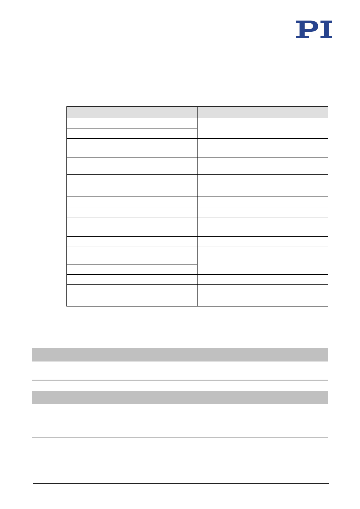
If a manual is missing or problems occur with downloading:
1.5 Other Applicable Documents
The devices and software tools from PI mentioned in this documentation are described in their
own manuals.
Product Document
E-505 piezo amplifier module
E-610 piezo amplifier / servo controller (OEM
module)
E-621 piezo amplifier / servo controller
module
E-625 piezo servo controller (benchtop device) PZ166E user manual
E-663 piezo amplifier PZ69E user manual
PZ70E user manual
PZ72E user manual
PZ160E user manual
E-665 piezo amplifier / servo controller PZ127E user manual
E-709 digital piezo controller PZ222E user manual
controller
E-727.xF digital multi-channel piezo controller
E-754 digital piezo controller E754T0001 user manual
PIMikroMove SM148E software manual
P-5xx / P-6xx / P-7xx piezo positioning systems PZ240EK short instructions
1.6 Downloading Manuals
INFORMATION
Contact our customer service department (p. 39).
PZ222E user manual
INFORMATION
For products that are supplied with software (CD in the scope of delivery), access to the
manuals is protected by a password. Protected content is only displayed on the website after
entering the access data.
You need the product CD to get the access data.
P-62x Positioning Systems PZ234E Version: 1.1.0 3
Page 8

1 About this Document
For products with CD: Get access data
1. Insert the product CD into the PC drive.
2. Switch to the Manuals directory on the CD.
3. In the Manuals directory, open the Release News (file including releasenews in the file
name).
4. Get the access data for downloading protected content in the "User login for software
download" section of the Release News. Possible methods for getting the access data:
− Link to a page for registering and requesting the access data
− User name and password is specified
5. If the access data needs to be requested via a registration page:
a) Follow the link in the Release News.
b) Enter the required information in the browser window.
c) Click Show login data in the browser window.
d) Note the user name and password shown in the browser window.
Downloading manuals
If you have requested access data for protected contents via a registration page (see above):
Click the links in the browser window to change to the content for your product and log
in using the access data that you received.
General procedure:
1. Open the website www.pi.ws.
2. If access to the manuals is protected by a password:
a) Click Login.
b) Log in with the user name and password.
3. Click Search.
4. Enter the product number up to the period (e.g., P-620) or the product family (e.g.,
PIHera) into the search field.
5. Click Start search or press the Enter key.
6. Open the corresponding product detail page in the list of search results:
a) If necessary: Scroll down the list.
4 Version: 1.1.0 PZ234E P-62x Positioning Systems
b) If necessary: Click Load more results at the bottom of the list.
c) Click the corresponding product in the list.
7. Click the Downloads tab.
The manuals are shown under Documentation.
8. Click the desired manual and save it to the hard disk of your PC or to a data storage
medium.
Page 9

2 Safety
Organizational Measures ............................................................................................................... 7
2
Safety
In this Chapter
Intended Use .................................................................................................................................. 5
General Safety Instructions............................................................................................................ 5
2.1 Intended Use
The P-62x is a laboratory device as defined by DIN EN 61010-1. It is intended to be used in
interior spaces and in an environment which is free of dirt, oil and lubricants.
Based on its design and realization, the P-62x is intended for fine positioning as well as the fast
and precise movement of small objects. The specifications of the P-62x apply to horizontal
mounting. Depending on the model, the motion is performed as follows:
in one axis horizontally or vertically
in two axes horizontally
Vertical mounting is only possible under certain conditions.
The intended use of the P-62x is only possible in combination with suitable electronics (p. 15)
that is available from PI. The electronics is not included in the scope of delivery of the P-62x.
The electronics must provide the required operating voltages. To ensure proper performance of
the servo control system, the electronics must be able to read out and process the signals from
the capacitive sensors.
2.2 General Safety Instructions
The P-62x is built according to state-of-the-art technology and recognized safety standards.
Improper use can result in personal injury and/or damage to the P-62x.
Only use the P-62x for its intended purpose, and only use it if it is in a good working
order.
Read the user manual.
Immediately eliminate any faults and malfunctions that are likely to affect safety.
The operator is responsible for the correct installation and operation of the P-62x.
P-62x Positioning Systems PZ234E Version: 1.1.0 5
Page 10

2 Safety
The P-62x is driven by piezo actuators. Temperature changes and compressive stresses can
induce charges in piezo actuators. After disconnection from the electronics, piezo actuators can
remain charged for several hours. Touching or short-circuiting the contacts in the connector of
the P-62x can lead to minor injuries from electric shock. The piezo actuators can be destroyed
by an abrupt contraction.
Do not open the P-62x.
Discharge the positioner's piezo actuators before installation:
Connect the positioner to the switched-off PI controller, which is equipped with an
internal discharge resistor.
Do not pull the plug connector out of the electronics during operation.
Positioners with Sub-D plug connector:
Touching the contacts in the plug connector can lead to an electric shock (max. 130 V DC) and
minor injuries.
Do not touch the contacts in the plug connector.
Secure the plug connector of the positioner with screws against being pulled out of the
controller.
If a protective earth conductor is not or not properly connected, dangerous touch voltages can
occur on the P-62x in the case of malfunction or failure of the system. If touch voltages exist,
touching the P-62x can result in minor injuries from electric shock.
Connect the P-62x to a protective earth conductor (p. 25) before startup.
Do not remove the protective earth conductor during operation.
If the protective earth conductor has to be removed temporarily (e.g., in the case of
modifications), reconnect the P-62x to the protective earth conductor before starting it
up again.
Mechanical forces can damage or misalign the P-62x.
Avoid impacts that affect the P-62x.
Do not drop the P-62x.
Do not exceed the maximum permissible stress and load capacities according to the
specifications (p. 41).
Touch the base body of the P-62x on the outside only.
The P-62x is maintenance-free and achieves its positioning accuracy as a result of the optimum
alignment of mechanical components and piezo actuators. Loosened screws cause a loss in
positioning accuracy.
Only loosen screws according to the instructions in this manual.
Do not open the P-62x.
6 Version: 1.1.0 PZ234E P-62x Positioning Systems
Page 11

2 Safety
2.3 Organizational Measures
User manual
Always keep this user manual available with the P-62x.
The latest versions of the user manuals are available for download (p. 3) on our
website.
Add all information from the manufacturer to the user manual, for example
supplements or technical notes.
If you give the P-62x to other users, also include this user manual as well as other
relevant information provided by the manufacturer.
Only use the device on the basis of the complete user manual. Missing information due
to an incomplete user manual can result in minor injury and damage to equipment.
Only install and operate the P-62x after you have read and understood this user
manual.
Personnel qualification
The P-62x may only be installed, started up, operated, maintained, and cleaned by authorized
and appropriately qualified personnel.
P-62x Positioning Systems PZ234E Version: 1.1.0 7
Page 12

Page 13
3 Product Description
Technical Features ....................................................................................................................... 16
P-620.1CD
PIHera precision linear nanopositioning system, 50 µm, direct position
P-620.1CL
PIHera precision linear nanopositioning system, 50 µm, direct position
P-620.10L
PIHera precision linear nanopositioning system, 60 µm, without sensor,
P-621.1CD
PIHera precision linear nanopositioning system, 100 µm, direct position
P-621.1CL
PIHera precision linear nanopositioning system, 100 µm, direct position
3
Product Description
In this Chapter
Model Overview ............................................................................................................................. 9
Product View ................................................................................................................................ 12
Product Labeling .......................................................................................................................... 13
Scope of Delivery ......................................................................................................................... 14
Suitable Electronics ...................................................................................................................... 15
Accessories ................................................................................................................................... 15
3.1 Model Overview
The P-62x is available in the following versions:
PIHera piezo linear stage
Model Description
measuring, capacitive sensor, Sub-D connector
measuring, capacitive sensor, LEMO connector(s)
LEMO connector(s)
measuring, capacitive sensor, Sub-D connector
measuring, capacitive sensor, LEMO connector(s)
P-621.10L PIHera precision linear nanopositioning system, 120 µm, without sensor,
LEMO connector(s)
P-622.1CD PIHera precision linear nanopositioning system, 250 µm, direct position
measuring, capacitive sensor, Sub-D connector
P-622.1CL PIHera precision linear nanopositioning system, 250 µm, direct position
measuring, capacitive sensor, LEMO connector(s)
P-622.10L PIHera precision linear nanopositioning system, 300 µm, without sensor,
LEMO connector(s)
P-625.1CD PIHera precision linear nanopositioning system, 500 µm, direct position
measuring, capacitive sensor, Sub-D connector
P-625.1CL PIHera precision linear nanopositioning system, 500 µm, direct position
measuring, capacitive sensor, LEMO connector(s)
P-62x Positioning Systems PZ234E Version: 1.1.0 9
Page 14
3 Product Description
P-625.10L
PIHera precision linear nanopositioning system, 600 µm, without sensor,
P-628.1CD
PIHera precision linear nanopositioning system, 800 µm, direct position
P-628.1CL
PIHera precision linear nanopositioning system, 800 µm, direct position
P-628.10L
PIHera precision linear nanopositioning system, 950 µm, without sensor,
ra precision linear nanopositioning system, 1800 µm, without sensor,
P-621.1U
PIHera precision linear nanopositioning system, 100 µm, direct position
P-622.1U
PIHera precision linear nanopositioning system, 250 µm, direct position
Precise PIHera XY nanopositioning system, 50 µm × 50 µm, direct position
P-620.2CL
Precise PIHera XY nanopositioning system, 50 µm × 50 µm, direct position
P-620.20L
Precise PIHera XY nanopositioning system, 60 µm × 60 µm, without
P-621.2CD
Precise PIHera XY nanopositioning system, 100 µm × 100 µm, direct
P-621.2CL
Precise PIHera XY nanopositioning system, 100 µm × 100 µm, direct
Model Description
LEMO connector(s)
measuring, capacitive sensor, Sub-D connector
measuring, capacitive sensor, LEMO connector(s)
LEMO connector(s)
P-629.1CD PIHera precision linear nanopositioning system, 1500 µm, direct position
measuring, capacitive sensor, Sub-D connector
P-629.1CL PIHera precision linear nanopositioning system, 1500 µm, direct position
measuring, capacitive sensor, LEMO connector(s)
P-629.10L PIHe
LEMO connector(s)
PIHera piezo linear stage (vacuum compatible to 10-9 hPa)
Model Description
measuring, capacitive sensor, Sub-D connector, vacuum compatible to
-9
hPa
10
measuring, capacitive sensor, Sub-D connector, vacuum compatible to
-9
hPa
10
PIHera piezo XY stage
Model Description
P-620.2CD
measuring, capacitive sensors, Sub-D connector
measuring, capacitive sensors, LEMO connector(s)
sensors, LEMO connector(s)
position measuring, capacitive sensors, Sub-D connector
position measuring, capacitive sensors, LEMO connector(s)
P-621.20L Precise PIHera XY nanopositioning system, 120 µm × 120 µm, without
sensors, LEMO connector(s)
P-622.2CD Precise PIHera XY nanopositioning system, 250 µm × 250 µm, direct
position measuring, capacitive sensors, Sub-D connector
10 Version: 1.1.0 PZ234E P-62x Positioning Systems
Page 15
3 Product Description
P-622.2CL
Precise PIHera XY nanopositioning system, 250 µm × 250 µm, direct
P-622.20L
Precise PIHera XY nanopositioning system, 300 µm × 300 µm, without
P-625.2CD
Precise PIHera XY nanopositioning system, 500 µm × 500 µm, direct
P-625.2CL
Precise PIHera XY nanopositioning system, 500 µm × 500 µm, direct
P-620.ZCD
Precise PIHera vertical nanopositioning stage, 50 µm, direct position
P-620.ZCL
Precise PIHera vertical nanopositioning stage, 50 µm, direct position
Model Description
position measuring, capacitive sensors, LEMO connector(s)
sensors, LEMO connector(s)
position measuring, capacitive sensors, Sub-D connector
position measuring, capacitive sensors, LEMO connector(s)
P-625.20L Precise PIHera XY nanopositioning system, 600 µm × 600 µm, without
sensors, LEMO connector(s)
P-628.2CD Precise PIHera XY nanopositioning system, 800 µm × 800 µm, direct
position measuring, capacitive sensors, Sub-D connector
P-628.2CL Precise PIHera XY nanopositioning system, 800 µm × 800 µm, direct
position measuring, capacitive sensors, LEMO connector(s)
P-628.20L Precise PIHera XY nanopositioning system, 1000 µm × 1000 µm, without
sensors, LEMO connector(s)
P-629.2CD Precise PIHera XY nanopositioning system, 1500 µm × 1500 µm, direct
position measuring, capacitive sensors, Sub-D connector
P-629.2CL Precise PIHera XY nanopositioning system, 1500 µm × 1500 µm, direct
position measuring, capacitive sensors, LEMO connector(s)
P-629.20L Precise PIHera XY nanopositioning system, 1800 µm × 1800 µm, without
sensors, LEMO connector(s)
PIHera piezo XY stage (vacuum compatible to 10-9 hPa)
Model Description
P-621.2U Precise PIHera XY nanopositioning system, 100 µm × 100 µm, direct
position measuring, capacitive sensors, Sub-D connector, vacuum
compatible to 10
-9
hPa
P-622.2U Precise PIHera XY nanopositioning system, 250 µm × 250 µm, direct
position measuring, capacitive sensors, Sub-D connector, vacuum
compatible to 10
-9
hPa
PIHera precision Z stage
Model Description
measuring, capacitive sensor, Sub-D connector
measuring, capacitive sensor, LEMO connector(s)
P-620.Z0L Precise PIHera vertical nanopositioning stage, 65 µm, without sensor,
LEMO connector(s)
P-62x Positioning Systems PZ234E Version: 1.1.0 11
Page 16
3 Product Description
P-621.ZCD
Precise PIHera vertical nanopositioning stage, 100 µm, direct position
P-621.ZCL
Precise PIHera vertical nanopositioning stage, 100 µm, direct position
P-621.Z0L
Precise PIHera vertical nanopositioning stage, 140 µm, without sensor,
P-622.ZCD
Precise PIHera vertical nanopositioning stage, 250 µm, direct position
Model Description
measuring, capacitive sensor, Sub-D connector
measuring, capacitive sensor, LEMO connector(s)
LEMO connector(s)
measuring, capacitive sensor, Sub-D connector
P-622.ZCL Precise PIHera vertical nanopositioning stage, 250 µm, direct position
measuring, capacitive sensor, LEMO connector(s)
P-622.Z0L Precise PIHera vertical nanopositioning stage, 350 µm, without sensor,
LEMO connector(s)
3.2 Product View
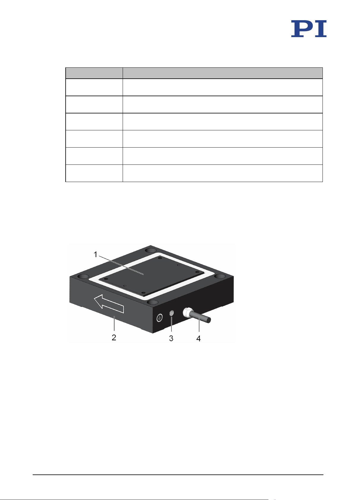
The figure serves as an example and can differ from your positioner model.
Pay attention to the symbols on your device.
Figure 1: Example of product view
1 Motion platform
2 Base body
3 Protective earth connection
4 Cable exit
12 Version: 1.1.0 PZ234E P-62x Positioning Systems
Page 17
3 Product Description
P-621.1CD
Product number (example), the digits after the period
123456789
Serial number (example), individual for each P-62x
Warning sign "Observe manual!"
WWW.PI.WS
Manufacturer's address (website)
Symbol for the protective earth conductor (p. 25)
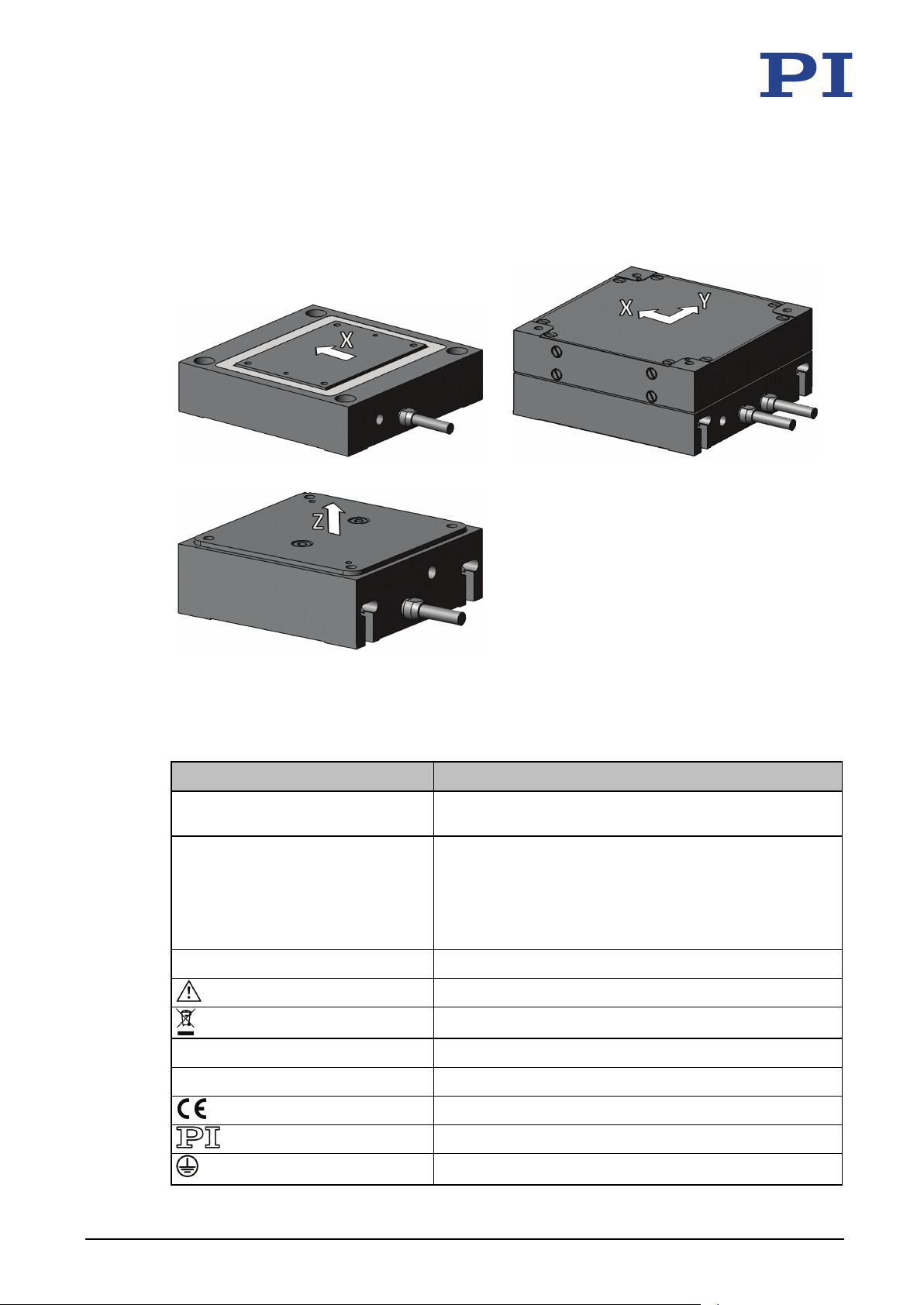
Directions of motion of the P-62x
The arrows indicate the positive direction of motion in each case.
P-62x.1x(x) P-62x.2x(x)
P-62x.Zxx
3.3 Product Labeling
Labeling Description
PIHera Brand name
Country of origin: Germany Country of origin
refer to the model
Meaning of the places (counting from left):
1 = internal information
2 and 3 = year of manufacture
4 to 9 = consecutive numbers
Old equipment disposal (p. 53)
CE conformity mark
P-62x Positioning Systems PZ234E Version: 1.1.0 13
Manufacturer's logo
Page 18
3 Product Description
P-62x
Positioner according to order (p. 9)
-
000036450
M4 screw set for protective earth, consisting of:
All models except
000036451
M2 screw set for protective earth, consisting of:
P-620
If applicable:
The arrows indicate the positive direction of motion.
The letter X, Y, and Z indicate the axis.
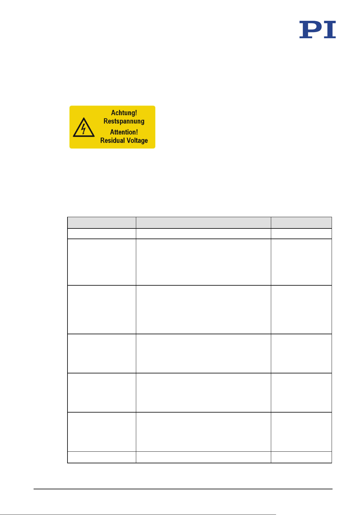
Figure 2: "Residual Voltage" warning sign on the connector of the P-62x
"Residual Voltage" warning: Risk of electric shock (p. 5) for models with Sub-D plug connector
3.4 Scope of Delivery
Product number Components Model
2491 Screw set, consisting of:
1 flat-head screw with cross recess, M4x8,
ISO 7045
2 safety washers
2 flat washers
4 socket head screws, M2x12, ISO 4762
4 safety washers
4 dowel pins, Ø 1 m6 x 4, ISO 8734
1 hex key
8 M3x10 socket head screws, DIN 7984
4 dowel pins Ø 1.5 m6 x 4, ISO 8734
1 hex key
P-620 and
P-621.2xx/.2U
P-621.2xx/.2U
P-622.2xx/.2U
P-625.2xx
P-628.2xx
000017112 Screw set, consisting of:
000011857 Screw set, consisting of:
PZ240EK Short instructions for piezo positioning systems All models
14 Version: 1.1.0 PZ234E P-62x Positioning Systems
4 socket head screws, M4x16, ISO 7984
4 dowel pins Ø 1.5 m6 x 4, ISO 8734
1 hex key
4 M3x10 socket head screws, DIN 7984
4 dowel pins Ø 1.5 m6 x 4, ISO 8734
1 hex key
P-629.2xx
P-621.Zxx
P-622.Zxx
Page 19
3 Product Description
E-625 piezo servo controller (benchtop device)
Sub-D 7W2
1
E-727.x • E-727.xAP digital multi-channel piezo
Sub-D 25W3
3
E-727.xF digital multi-channel piezo controller
Sub-D 25W3
3
E-712 digital piezo controller (modular system)
Sub-D 25W3
3/6
P-895.2D1DDC*
Adapter cable Sub-D 25W3 (f) and Sub-D 7W2 (f) to Sub-D 25W3 (m) for
P-895.2DDC
Adapter cable 2× Sub-D 7W2 (f) to Sub-D 25W3 (m) for piezo actuator
3.5 Suitable Electronics
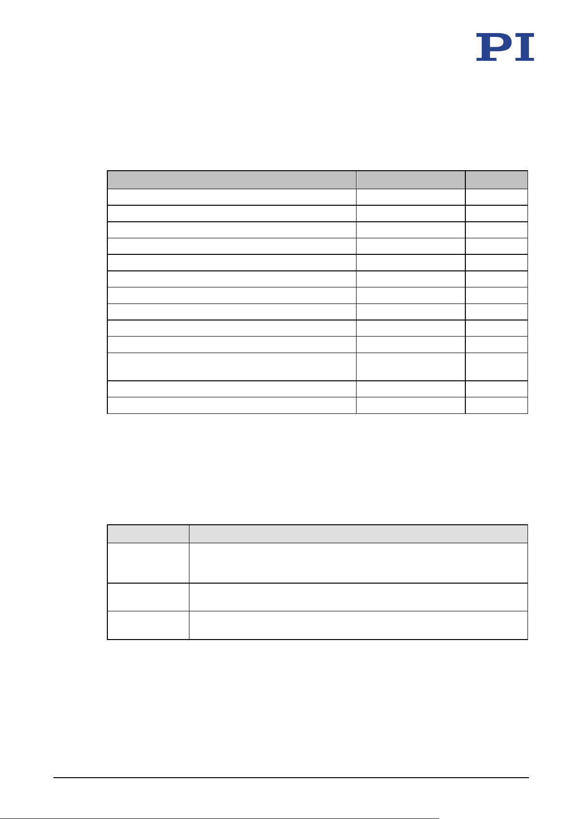
To operate a P-62x, you need suitable electronics. Selection of the device depends on the
application and the connections available.
Electronics Connector* Channels**
E-505 piezo amplifier module LEMO 1
E-610 piezo amplifier / servo controller (OEM module) LEMO 1
E-503 piezo amplifier module LEMO 3
E-663 piezo amplifier LEMO 3
E-621 piezo amplifier / servo controller module Sub-D 7W2 1
E-665 piezo driver / servo controller (benchtop device) Sub-D 7W2 1
E-709 digital piezo controller Sub-D 7W2 1
E-709.1CC885 digital piezo controller module Sub-D 7W2 1
E-754 digital piezo controller Sub-D 7W2 1
controller
* In some cases, adapter cables (p. 15) are necessary for connecting.
** When using single-channel electronics, each motion axis requires its own individual
electronics.
3.6 Accessories
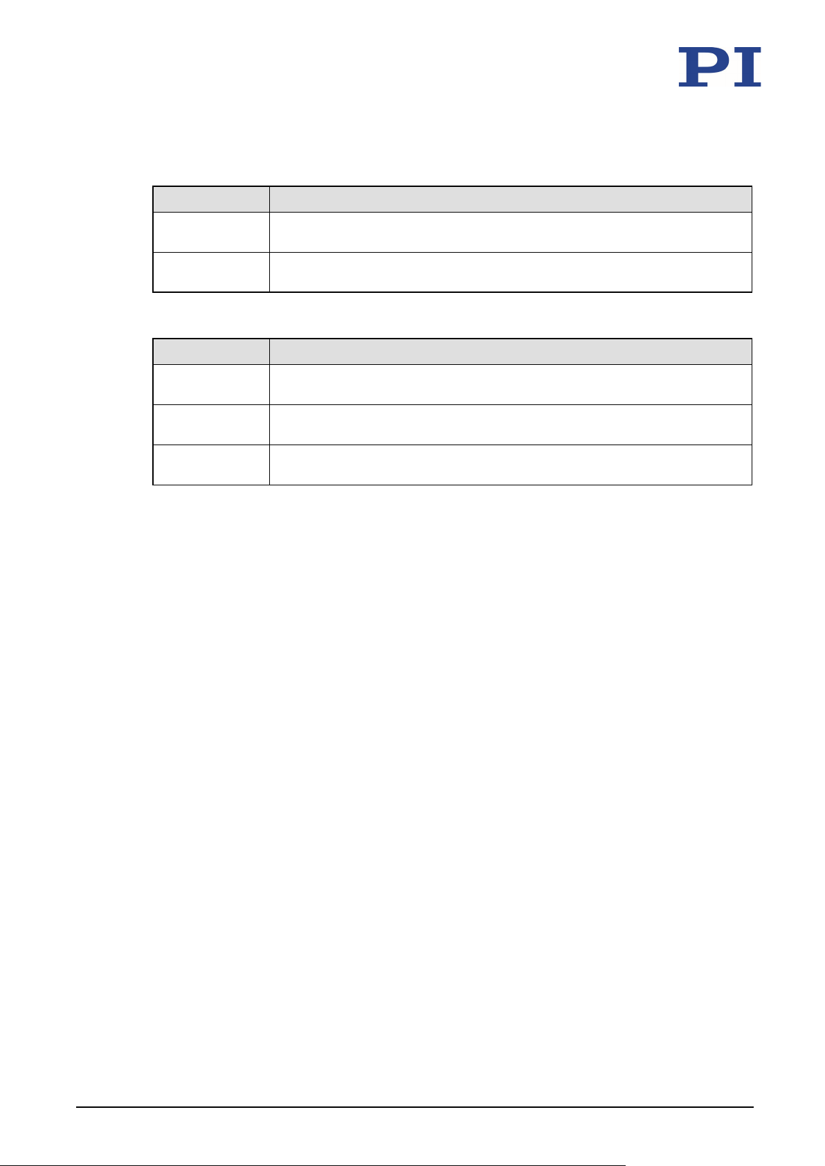
Adapter cable for models with Sub-D plug connector(s)
Product number Description
P-895.3DDC Adapter cable 3× Sub-D 7W2 (f) to Sub-D 25W3 (m) for piezo actuator
* 2 channels to Sub-D 25W3 (f) and 1 channel to Sub-D 7W2 (f) available.
piezo actuator nanopositioning systems with capacitive sensors, 3 channels,
length: 0.3 m.
nanopositioning systems with capacitive sensors, 2 channels, length: 0.3 m.
nanopositioning systems with capacitive sensors, 3 channels, length: 0.3 m.
P-62x Positioning Systems PZ234E Version: 1.1.0 15
Page 20
3 Product Description
P-890.1CV
Vacuum feedthrough for piezo voltage to 130 V and sensor signal
P-890.2CV
Vacuum feedthrough for piezo voltage to 130 V and sensor signal
Adapter cable for models with LEMO plug connectors
Product number Description
P-895.1LDC Adapter cable LEMO to Sub-D 7W2 (m) for piezo actuator nanopositioning
systems with capacitive sensors, 1 channel, length: 0.3 m.
P-895.3LDC Adapter cable LEMO to Sub-D 25W3 (m) for piezo actuator nanopositioning
systems with capacitive sensors, 3 channels, length: 0.3 m.
Accessories for vacuum-compatible models
Product number Description
(capacitive sensor), 1 channel, to 10-9 hPa, bakeout to 150 °C
(capacitive sensor), 2 channels, to 10-9 hPa, bakeout to 150 °C
K030B0392 Adapter cable, Sub-D 5W1 to Sub-D 7W2, 1 channel, 2 m, for connecting to
P-890.1CV or P-890.2CV vacuum feedthrough*
To order, contact our customer service department (p. 39).
3.7 Technical Features
3.7.1 PICMA® Piezo Actuators
P-62x positioners are driven by PICMA® piezo actuators. PICMA® actuators have all-ceramic
insulation and their performance and lifetime are therefore far superior to conventional
actuators. The ceramic insulation layer protects the monolithic piezoceramic block against
humidity and failure due to increased leakage current. In this way, an especially high reliability
is achieved even under extreme ambient conditions. In contrast to motorized drives, there are
no rotating parts or friction. The piezo actuators are therefore free of backlash, maintenance,
3.7.2 Flexure Guides
and wear.
P-62x positioners have flexure guides for friction-free motion and high guiding accuracy.
A flexure guide is an element that is free of static and sliding friction. It is based on the elastic
deformation (bending) of a solid (e.g., steel) and does not have any rolling or sliding parts.
Flexure elements have a high stiffness and load capacity. Flexure guides are maintenance and
wear free. They are 100 % vacuum compatible, function in a wide temperature range and do
not require any lubricants.
16 Version: 1.1.0 PZ234E P-62x Positioning Systems
Page 21

3 Product Description
3.7.3 Capacitive Sensors
Except for the models P-62x.x0L, all P-62x are equipped with capacitive sensors.
Capacitive sensors measure the position directly on the motion platform (direct metrology) and
work without contact. Neither friction nor hysteresis interferes with the motion, which allows
excellent linearity values to be achieved together with the high position resolution. In
conjunction with suitable electronics, capacitive sensors achieve the best resolution, stability,
and bandwidth.
3.7.4 ID Chip (Models with Sub-D 7W2 Connector Only)
An ID chip is located in the Sub-D connector of the P-62x. When the P-62x is calibrated at the
factory with digital electronics, the calibration data is saved on the ID chip together with
specific product information. During switch-on, the digital electronics read the data from the
ID chip of the P-62x connected. An P-62x, whose ID chip contains the calibration data, can
therefore be connected to any suitable digital electronics without renewed calibration.
For more information on the ID chip, see the manual of the controller used.
P-62x Positioning Systems PZ234E Version: 1.1.0 17
Page 22

Page 23
4 Unpacking
4
Unpacking
NOTICE
Mechanical overload due to incorrect handling!
An impermissible mechanical load on the motion platform of the P-62x can cause damage to
the piezo actuators, sensors, and flexures of the P-62x as well as loss of accuracy.
Touch the base body of the P-62x on the outside only.
INFORMATION
When handling the vacuum version of the positioner, attention must be paid to appropriate
cleanliness. At PI, all parts are cleaned before assembly. Powder-free gloves are worn during
assembly and measuring. In addition, the positioner is wipe cleaned afterwards and then
shrink-wrapped twice in vacuum-compatible film.
Touch the positioner only with powder-free gloves.
If necessary, wipe the positioner clean after unpacking.
1. Unpack the P-62x with care.
2. Compare the contents with the items listed in the contract and the packing list.
3. Inspect the contents for signs of damage. If parts are missing or you notice signs of
damage, contact PI immediately.
4. Keep all packaging materials in case the product needs to be returned.
P-62x Positioning Systems PZ234E Version: 1.1.0 19
Page 24

Page 25
5 Installation
Connecting the Vacuum Version to the Electronics .................................................................... 29
5
Installation
In this Chapter
General Notes on Installation ...................................................................................................... 21
Mounting the Positioner and Affixing the Load ........................................................................... 22
Connecting the P-62x to the Protective Earth Conductor ........................................................... 25
5.1 General Notes on Installation
CAUTION
Dangerous voltage and residual charge in piezo actuators!
The P-62x is driven by piezo actuators. Temperature changes and compressive stresses can
induce charges in piezo actuators. After disconnection from the electronics, piezo actuators
can remain charged for several hours. Touching or short-circuiting the contacts in the
connector of the P-62x can lead to minor injuries from electric shock. The piezo actuators can
be destroyed by an abrupt contraction.
Do not open the P-62x.
Discharge the positioner's piezo actuators before installation:
Connect the positioner to the switched-off PI controller, which is equipped with an internal
discharge resistor.
Do not pull the plug connector out of the electronics during operation.
Positioners with Sub-D plug connector:
Touching the contacts in the plug connector can lead to an electric shock (max. 130 V DC) and
minor injuries.
Do not touch the contacts in the plug connector.
Secure the plug connector of the positioner with screws against being pulled out of the
controller.
NOTICE
Mechanical overload due to incorrect handling!
An impermissible mechanical load on the motion platform of the P-62x can cause damage to
the piezo actuators, sensors, and flexures of the P-62x as well as loss of accuracy.
Touch the base body of the P-62x on the outside only.
P-62x Positioning Systems PZ234E Version: 1.1.0 21
Page 26
5 Installation
Extended cables can reduce the positioning accuracy of the P-62x or affect the sensor
NOTICE
Damage due to unsuitable cables!
Unsuitable cables can damage the P-62x and the electronics.
Only use cables provided by PI for connecting the P-62x to the electronics.
NOTICE
Damage due to incorrectly tightened screws!
Incorrectly tightened screws can cause damage.
Observe the torque range (p. 50) given for the screws used during installation.
INFORMATION
processing by the electronics.
Do not use cable extensions. If you need longer cables, contact our customer service
department (p. 39).
5.2 Mounting the Positioner and Affixing the Load
NOTICE
Protruding screw heads!
Protruding screw heads can damage the P-62x.
Ensure that the screw heads do not protrude from countersunk holes so that they do not
interfere with the motion.
NOTICE
Screws that are too long!
The P-62x can be damaged by screws that are too long.
Note the depth of the mounting holes in the motion platform (p. 47).
Only use screws of the correct length for the respective mounting holes.
22 Version: 1.1.0 PZ234E P-62x Positioning Systems
Page 27
5 Installation
62x has two holes each on the bottom side of the base body and on the motion platform
The directions of motion of the P-62x are indicated in the product view (p. 12).
NOTICE
Warping of the P-62x due to mounting on uneven surfaces!
Mounting the P-62x onto an uneven surface can warp the P-62x. Warping reduces the
accuracy.
Mount the P-62x onto an even surface. The recommended evenness of the surface is
≤20 µm.
For applications with large temperature changes:
Only mount the P-62x onto surfaces that have the same or similar thermal expansion
properties as the P-62x (e.g., surfaces made of aluminum).
NOTICE
Tensile stress on piezo actuator with vertical mounting!
When the positioner is mounted vertically, certain alignments can cause tensile stress, which
reduces the preload and destroys the piezo actuator.
If you want to mount the P-62x vertically, contact our customer service department (p. 39).
INFORMATION
In order to facilitate mounting with screws, you can fix the P-62x or loads using dowel pins.
The Pto accommodate dowel pins.
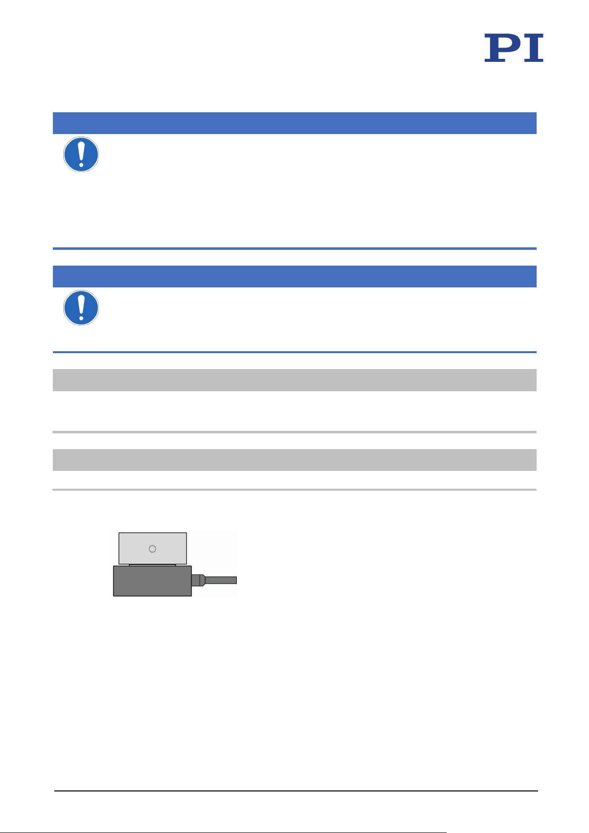
INFORMATION
Center of load at the optimum position:
Figure 3: Example of an optimally placed load
P-62x Positioning Systems PZ234E Version: 1.1.0 23
Page 28
5 Installation
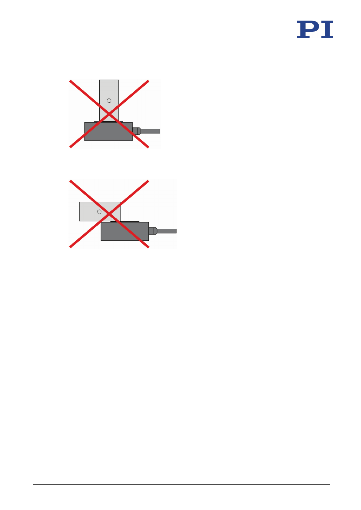
Center of load at an unsuitable position:
Figure 4: Tall load and center of load too far above the motion platform
Figure 5: Unwanted lever effect and center of load on the side of the motion platform
Requirements
You have read and understood the general notes on installation (p. 21).
The P-62x is not connected to the controller.
Tools and accessories
If a screw set for mounting the positioner onto a surface is not in the scope of delivery
(p. 14):
− Screws of suitable size and length (p. 47)
− Optional: Dowel pins of suitable size and length (p. 47)
If a screw set for mounting the positioner onto a surface is in the scope of delivery
(p. 14):
− Screws supplied for mounting the positioner onto a surface
− Optional: Dowel pins supplied for aligning the positioner or loads
Suitable tools
24 Version: 1.1.0 PZ234E P-62x Positioning Systems
Page 29

5 Installation
In the case of P-62x positioners with Sub-D connectors, ground loops can occur when the
Observe the applicable standards for connecting the protective earth conductor.
Mounting the P-62x and affixing the load
1. Alignment (optional):
− Align the positioner using the locating holes (p. 47) in the base body and suitable
dowel pins.
− Align the load using the locating holes (p. 47) in the motion platform of the P-62x
and suitable dowel pins.
2. Mounting:
− Only mount the positioner onto the mounting holes (p. 47) provided. If the
positioner is not equipped with a separate protective earth connection, follow the
instructions for connecting the protective earth connector via the mounting holes
(p. 25) when mounting the positioner.
− Only affix loads to the threaded holes (p. 47) provided.
5.3 Connecting the P-62x to the Protective Earth Conductor
INFORMATION
positioner is grounded via its protective earth connection as well as by the shield of the
connecting cable for the electronics.
If a ground loop occurs, contact our customer service department (p. 39).
INFORMATION
The connection of the P-62x to the protective earth conductor depends on the model:
Models with separate protective earth connection (all except P-620 and P-621.2xx/.2U)
Models without separate protective earth connection (P-620 and P-621.2xx/.2U only)
P-62x Positioning Systems PZ234E Version: 1.1.0 25
Page 30
5 Installation
Separate protective earth connection available
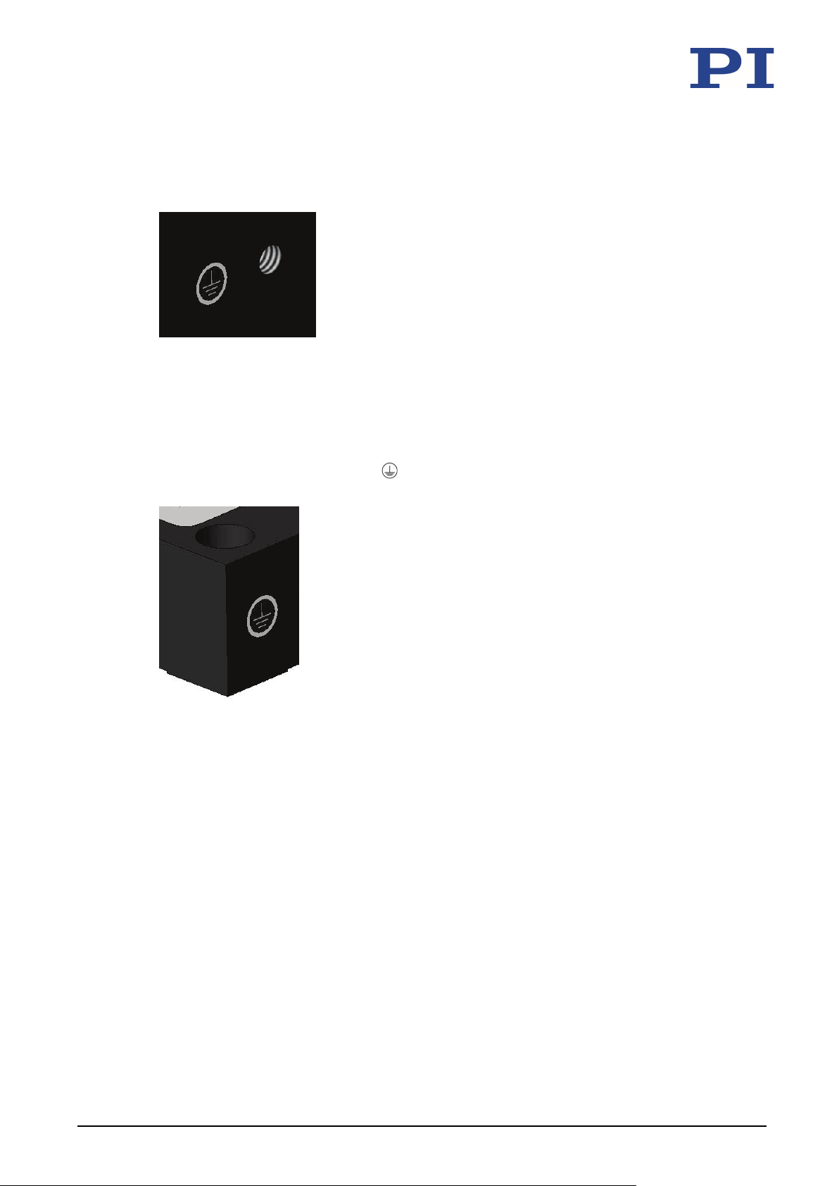
If a separate protective earth connection is available, it must be used.
Figure 6: Protective earth connection
No separate protective earth connection
If a separate protective earth connection is not available, all mounting holes marked with the
protective earth conductor symbol
protective earth conductor.
must be used to ensure proper connection of the
Figure 7: Mounting hole with symbol for the protective earth conductor
Tools and accessories
Suitable protective earth conductor: Cable cross section ≥ 0.75 mm2
Suitable screwdriver
All models except P-620 and P-621.2xx/.2U: M4 protective earth conductor screw set
(p. 14) for connecting the protective earth conductor
When mounting a P-620 and a P-621.2xx/.2U:
− Screw set (p. 14) for mounting the positioner onto a surface
− Suitable surface: The surface where the positioner is to be mounted must be
connected to a suitable protective earth conductor. The surfaces that make contact
with the positioner, usually the holes for accommodating the mounting screws,
must be sufficiently conductive.
Requirements
You have read and understood the general notes on installation (p. 21).
The P-62x is not connected to the controller.
26 Version: 1.1.0 PZ234E P-62x Positioning Systems
Page 31
5 Installation
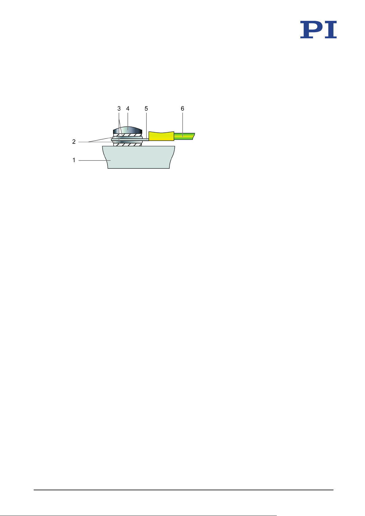
Connecting the protective earth conductor to the separate protective earth connection (all models except P-620 and P-621.2xx/.2U)
Figure 8: Connecting the protective earth conductor (profile view)
1 Base body of the P-62x
2 Flat washer
3 Safety washer
4 Screw
5 Cable lug
6 Protective earth conductor
1. If necessary, attach a suitable cable lug to the protective earth conductor.
2. Use the M4 screw (together with the washers and self-locking washers) to affix the
cable lug of the protective earth conductor to the protective earth connection of the
P-62x as shown in the profile view.
3. Tighten the M4 screw with a torque of 1.2 Nm to 1.5 Nm.
4. Make sure that the contact resistance at all connection points relevant for connecting
the protective earth conductor is <0.1 Ω at 25 A.
P-62x Positioning Systems PZ234E Version: 1.1.0 27
Page 32
5 Installation
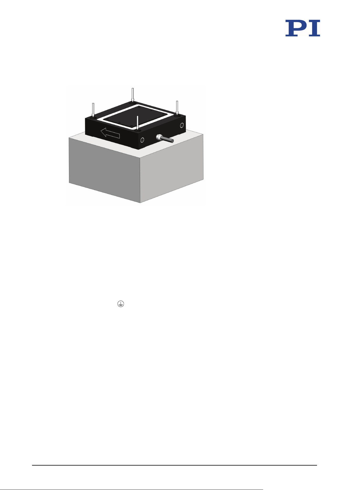
Connecting the protective earth conductor via the mounting holes (P-620 and P-621.2xx/.2U only)
Figure 9: Positioner on a surface that must be connected to a protective earth conductor; for
mounting holes, see arrows.
1. Optional: Align the positioner using the locating holes (p. 47) in the base body and the
dowel pins supplied.
2. Mount the positioner onto an electrically conductive surface that is connected to a
suitable protective earth conductor:
a) If the screw set includes safety washers, place a safety washer onto each screw.
b) Insert a screw into each of the four mounting holes (see figure). If safety washers
are intended, insert each screw together with the safety washer.
The mounting holes are marked respectively with the protective earth conductor
symbol
.
c) Tighten each of the four screws with at least four turns to the torque (p. 50)
specified for the screws.
3. Make sure that the contact resistance is <0.1 Ω at 25 A at all connection points relevant
for attaching the protective earth conductor.
28 Version: 1.1.0 PZ234E P-62x Positioning Systems
Page 33

5 Installation
This section describes connection of the vacuum version of the P-62x to electronics with Sub-D
5.4 Connecting the Vacuum Version to the Electronics
INFORMATION
7W2 socket. For connecting electronics with Sub-D 25W3, you also need a suitable P-895
adapter cable (p.
15) that is connected to the Sub-D 25W3 socket of the electronics.
Requirements
You have read and understood the general notes on installation (p. 21).
The electronics are switched off, i.e., not connected to the power supply.
You have connected the P-62x to the protective earth conductor (p. 25).
You have installed the P-890 vacuum feedthrough (p. 15) into your vacuum chamber:
− Use the P-890.1CV vacuum feedthrough for operating single-axis positioners.
− Use the P-890.2CV vacuum feedthrough for operating two-axis positioners.
Optionally, it is also possible to use two P-890.1CV vacuum feedthroughs.
Tools and accessories
For .1U models only: K030B0392 adapter cable (p. 15)
For .2U models only: Two K030B0392 adapter cables (p. 15)
Connecting the vacuum version to the electronics
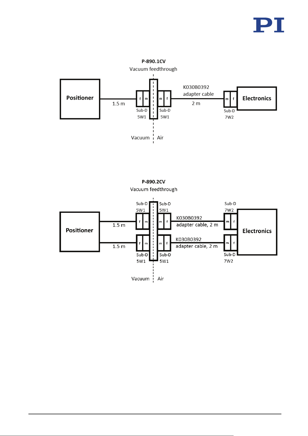
Connect the P-62x ("positioner"), vacuum feedthrough, and electronics as shown in the
connection diagram below.
− Pay attention to the assignment that is specified on the labeling of the sockets, plug
connectors, and cables.
P-62x Positioning Systems PZ234E Version: 1.1.0 29
Page 34
5 Installation
Figure 10: Connection of the .1U vacuum version to the electronics with P-890.1CV vacuum
feedthrough
Figure 11: Connection of the .2U vacuum version to the electronics with P-890.2CV vacuum
feedthrough
30 Version: 1.1.0 PZ234E P-62x Positioning Systems
Page 35
6 Startup and Operation
Discharging the P-62x .................................................................................................................. 33
6
Startup and Operation
In this Chapter
General Notes on Startup and Operation .................................................................................... 31
Operating the P-62x ..................................................................................................................... 33
6.1 General Notes on Startup and Operation
CAUTION
Risk of electric shock if the protective earth conductor is not connected!
If a protective earth conductor is not or not properly connected, dangerous touch voltages can
occur on the P-62x in the case of malfunction or failure of the system. If touch voltages exist,
touching the P-62x can result in minor injuries from electric shock.
Connect the P-62x to a protective earth conductor (p. 25) before startup.
Do not remove the protective earth conductor during operation.
If the protective earth conductor has to be removed temporarily (e.g., in the case of
modifications), reconnect the P-62x to the protective earth conductor before starting it up
again.
NOTICE
Destruction of the piezo actuator due to electric flashovers!
Using the P-62x in environments that increase the electrical conductivity can lead to the
destruction of the piezo actuator by electric flashovers. Electric flashovers can be caused by
moisture, high humidity, liquids, and conductive materials (e.g., metal dust). In addition,
electric flashovers can also occur in certain air pressure ranges due to the increased
conductivity of the air.
Avoid operating the P-62x in environments that can increase the electrical conductivity.
Only operate the P-62x within the permissible ambient conditions and classifications
(p. 46).
When using in a vacuum under 0.1 hPa:
Do not operate the P-62x during evacuating or ventilation.
P-62x Positioning Systems PZ234E Version: 1.1.0 31
Page 36
6 Startup and Operation
When connecting the positioner, pay attention to the assignment of the motion axes to the
NOTICE
Reduced lifetime of the piezo actuator due to permanently high voltage!
The permanent application of a high static voltage to piezo actuators leads to a considerable
reduction in the lifetime of the piezo ceramic.
When the P-62x is not used but the electronics remain switched on to ensure temperature
stability, discharge the P-62x (p. 33).
NOTICE
Uncontrolled oscillation!
Oscillation can cause irreparable damage to the P-62x. Oscillation is indicated by a humming
noise and can be caused by the following:
A change in the load and/or dynamics requires the servo control parameters to be
adjusted.
The P-62x is operated near to its resonant frequency.
If you notice oscillation:
In closed-loop operation, switch off the servo mode immediately.
In open-loop operation, stop the P-62x immediately.
INFORMATION
The directions of motion of the P-62x are indicated in the product view (p. 12).
INFORMATION
Systems are calibrated at the factory to achieve optimum positioning accuracy. Replacing the
system components can lead to a reduction of position accuracy when positioners are used
with an ID-chip that does not contain calibration data or when LEMO plug connectors are used.
controller channels, which is specified on the calibration label of the controller.
If position accuracy is reduced after replacing the P-62x or the controller:
Perform a recalibration of the axis displacement (see controller manual) or contact our
customer service department (p. 39).
INFORMATION
Sound and vibration (e.g., footfall, knocks) can be transmitted to the P-62x and can affect its
performance with regard to position stability.
Avoid sound and vibration while the P-62x is being operated.
INFORMATION
The expansion of the piezo actuators depends on the ambient temperature and can vary by up
to 20 % in the given temperature ranges.
32 Version: 1.1.0 PZ234E P-62x Positioning Systems
Page 37

6 Startup and Operation
6.2 Operating the P-62x
Follow the instructions in the manual for the electronics (p. 15) used for startup and
operation of the P-62x.
6.3 Discharging the P-62x
The P-62x must be discharged in the following cases:
Before installation
If the P-62x is not used and the controller remains switched on to ensure temperature
stability
Before demounting (e.g., before cleaning and transporting the P-62x and for
modifications)
The P-62x is discharged via the internal discharge resistor of the controller from PI.
Discharging an P-62x that is connected to the controller
In closed-loop operation:
1. Switch off the servo mode on the controller.
2. Set the piezo voltage to 0 V on the controller.
In open-loop operation:
Set the piezo voltage to 0 V on the controller.
Discharging an P-62x that is not connected to the controller
Connect the P-62x to the switched-off controller from PI.
P-62x Positioning Systems PZ234E Version: 1.1.0 33
Page 38

Page 39
7 Maintenance
Cleaning the P-62x ....................................................................................................................... 35
7
Maintenance
In this Chapter
General Notes on Maintenance ................................................................................................... 35
7.1 General Notes on Maintenance
NOTICE
Misalignment from loosening screws!
The P-62x is maintenance-free and achieves its positioning accuracy as a result of the optimum
alignment of mechanical components and piezo actuators. Loosened screws cause a loss in
positioning accuracy.
Loosen any screws only when instructed in this manual.
Do not open the P-62x.
7.2 Cleaning the P-62x
Requirements
You have discharged the piezo actuators of the P-62x (p. 33).
You have disconnected the P-62x from the controller.
Cleaning the P-62x
Do not do any ultrasonic cleaning.
Only when the positioner is not used in vacuum:
Clean the surfaces of the P-62x with a cloth that is dampened with a mild cleanser or
disinfectant (e.g., isopropyl alcohol).
When the positioner is used in a vacuum:
Touch the positioner only with powder-free gloves.
If necessary, wipe the positioner clean.
P-62x Positioning Systems PZ234E Version: 1.1.0 35
Page 40

Page 41
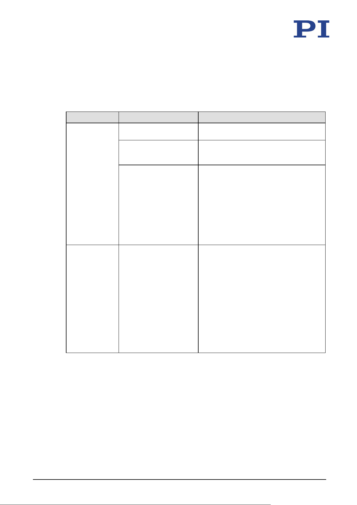
8 Troubleshooting
The contact surface of the load has an
8
Troubleshooting
Problem Possible causes Solution
No or limited
motion
Cable not connected
correctly
Excessive load Do not exceed the maximum permissible
Zero shift of the sensor for
the following reasons:
Load in direction of
motion
Ambient/operating
temperature of the
positioner is far above
or below the calibration
temperature (21 °C to
24 °C)
Reduced accuracy Warping of the base body
or the motion platform
Check the cable connections.
stress and load capacities according to
the specifications (p.
Perform a zero-point adjustment of the
sensor (see controller manual).
Only mount the P-62x on surfaces with
the following characteristics:
− Flatness of at least 20 μm
− The thermal expansion properties are
similar to those of the P-62x (e.g.,
surfaces made of aluminum).
Only mount loads with the following
characteristics on the P-62x:
−
flatness of at least 20 μm.
− The thermal expansion properties are
similar to those of the P-62x (e.g.,
loads made of aluminum).
41).
P-62x Positioning Systems PZ234E Version: 1.1.0 37
Page 42
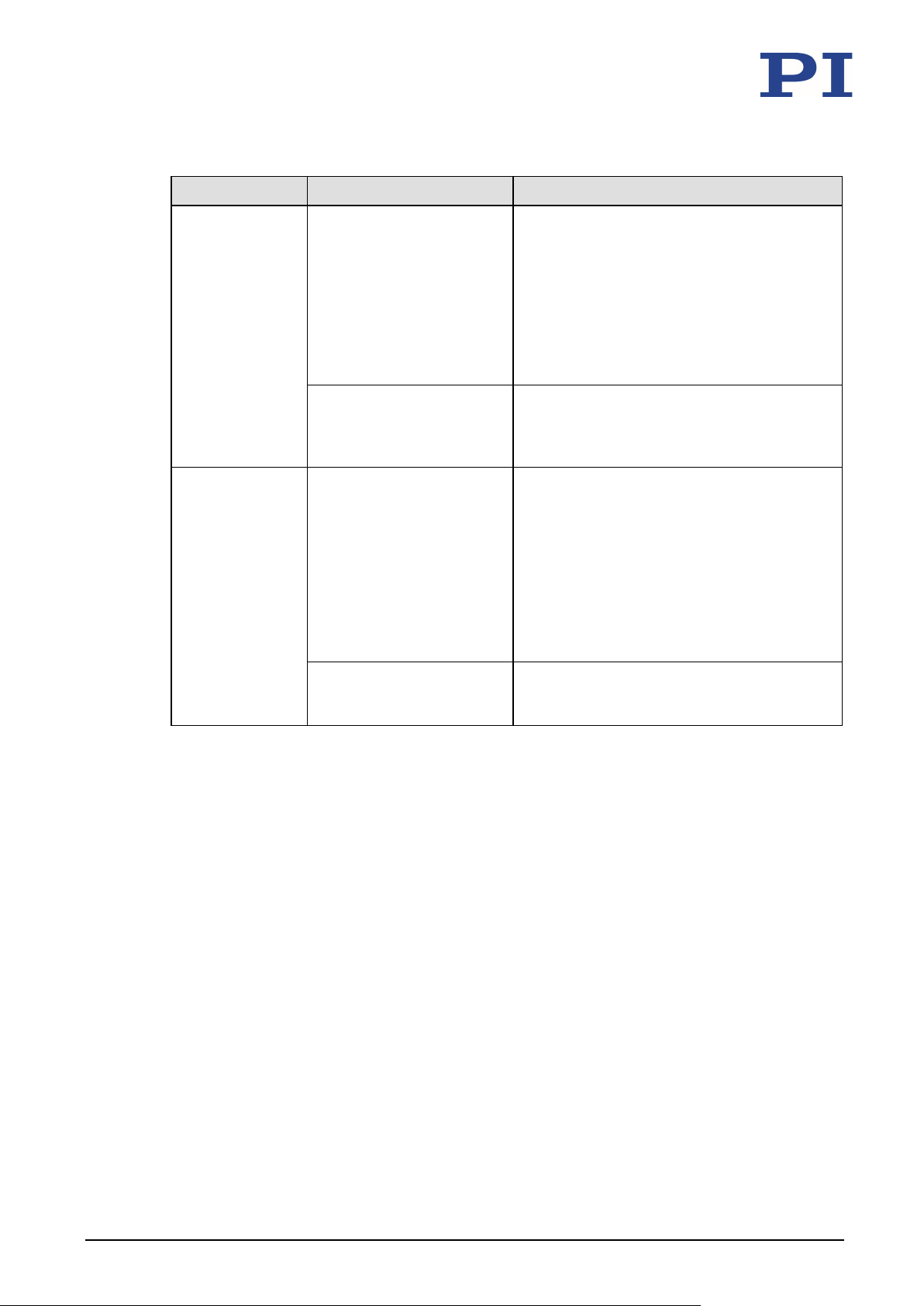
8 Troubleshooting
P-62x or controller has been
When using positioners, whose ID chip does
Problem Possible causes Solution
replaced
not contain any calibration data, or LEMO
plug connectors, axis displacement has to be
recalibrated after the P-62x or the controller
has been replaced.
Perform a recalibration of the axis
displacement (see controller manual) or
contact our customer service department
(p. 39).
Axes were mixed up during
connection
Pay attention to the assignment of the
axes when connecting the positioner to
the controller. This assignment is
indicated by labels on the devices.
The positioner
starts oscillating
or positions
inaccurately
Servo control parameters
incorrectly set because for
example, the load was
changed
1. Switch off the servo mode of the
corresponding motion axes immediately.
2. Check the settings of the servo control
parameters on the controller.
3. Adjust the servo control parameters on
the controller according to the load
change.
Open-loop operation near
the resonant frequency
In open-loop operation, operate the
positioner only with a frequency that is
below the resonant frequency.
If the problem that occurred with your system is not listed in the table above or cannot be
solved as described, contact our customer service department (p. 39).
38 Version: 1.1.0 PZ234E P-62x Positioning Systems
Page 43

9 Customer Service
9
Customer Service
For inquiries and orders, contact your PI sales engineer or send us an email ([email protected]).
If you have questions concerning your system, have the following information ready:
− Product and serial numbers of all products in the system
− Firmware version of the controller (if available)
− Version of the driver or the software (if available)
− Operating system on the PC (if available)
If possible: Take photographs or make videos of your system that can be sent to our
customer service department if requested.
The latest versions of the user manuals are available for download (p. 3) on our website.
P-62x Positioning Systems PZ234E Version: 1.1.0 39
Page 44

Page 45

10 Technical Data
Pin Assignment ............................................................................................................................ 50
10
Technical Data
In this Chapter
Specifications ............................................................................................................................... 41
Dimensions .................................................................................................................................. 47
Torque for Stainless Steel Screws (A2-70) ................................................................................... 50
10.1 Specifications
10.1.1 Data Table
Active axes X X X X X X
Motion and positioning
Integrated sensor Capacitive Capacitive Capacitive Capacitive Capacitive Capacitive
Travel range at -20 to
120 V, open loop
Travel range, closed loop 50 100 250 500 800 1500 µm
Resolution, closed loop /
open loop
Linearity error, closed loop 0.02 0.02 0.02 0.03 0.03* 0.03** % typ.
Repeatability ±1 ±1 ±1 ±5 ±10 ±14 nm typ.
Pitch / yaw ±3 ±3 ±3 ±6 ±6 ±30 / ±10 µrad typ.
Mechanical properties
Stiffness in motion
direction
Resonant frequency, no
load
Resonant frequency, under
load, 20 g
Resonant frequency, under
load, 120 g
Push / pull force capacity in
motion direction
Load capacity 10 10 10 10 10 10 N max.
Lateral load capacity 10 10 10 10 10 8 N max.
Drive properties
Piezo ceramic PICMA®
Electrical capacitance 0.35 1.5 3.1 6.2 19 52 µF ±20 %
P-620.1CD
P-620.1CL
60 120 300 600 950 1800 µm +20 % /
0.2 / 0.1 0.4 / 0.2 0.7 / 0.4 1.4 / 0.5 1.8 / 0.5 3 / 2 nm typ.
0.42 0.35 0.2 0.1 0.12 0.13 N/µm ±20 %
1100 800 400 215 125 125 Hz ±20 %
550 520 340 180 115 120 Hz ±20 %
260 240 185 110 90 110 Hz ±20 %
10 10 10 10 10 10 N max.
P-883
P-621.1CD
P-621.1CL
PICMA®
P-885
P-622.1CD
P-622.1CL
PICMA®
P-885
P-625.1CD
P-625.1CL
PICMA®
P-885
P-628.1CD
P-628.1CL
PICMA®
P-887
P-629.1CD
P-629.1CL
PICMA®
P-888
Unit Tole-
rance
-0 %
P-62x Positioning Systems PZ234E Version: 1.1.0 41
Page 46

10 Technical Data
Miscellaneous
Operating temperature
range
Material Aluminum Aluminum Aluminum Aluminum Aluminum Aluminum
Dimensions 30 mm ×
Mass 0.11 0.16 0.2 0.24 0.38 0.72 kg ±5 %
Cable length 1.5 1.5 1.5 1.5 1.5 1.5 m ±10 mm
Sensor / voltage connection CD
Recommended electronics E-503,
* With digital controller. With analog controllers 0.05 %.
** With digital controller. With analog controllers 0.07 %.
The resolution of the system is limited only by the noise of the amplifier and the measuring technology because PI piezo
nanopositioning systems are free of friction.
Vacuum-compatible versions to 10
versions can differ.
Versions without sensor are available under the P-62x.10L order numbers; operating temperature range -20 to 150 °C.
P-620.1CD
P-620.1CL
-20 to 80 -20 to 80 -20 to 80 -20 to 80 -20 to 80 -20 to 80 °C
30 mm ×
12 mm
versions:
Sub-D 7W2
CL versions:
LEMO
E-505,
E-610,
E-621,
E-625,
E-665,
E-709,
E-709.1CC8
85, E-754
-9
P-621.1CD
P-621.1CL
40 mm ×
40 mm ×
15 mm
CD
versions:
Sub-D 7W2
CL versions:
LEMO
E-503,
E-505,
E-610,
E-621,
E-625,
E-665,
E-709,
E-709.1CC8
85, E-754
hPa are available under the order numbers P-621.1U and P-622.1U. Specifications for vacuum
P-622.1CD
P-622.1CL
50 mm ×
50 mm ×
15 mm
CD
versions:
Sub-D 7W2
CL versions:
LEMO
E-503,
E-505,
E-610,
E-621,
E-625,
E-665,
E-709,
E-709.1CC8
85, E-754
P-625.1CD
P-625.1CL
60 mm ×
60 mm ×
15 mm
CD
versions:
Sub-D 7W2
CL versions:
LEMO
E-503,
E-505,
E-610,
E-621,
E-625,
E-665,
E-709,
E-709.1CC8
85, E-754
P-628.1CD
P-628.1CL
80 mm ×
80 mm ×
17 mm
CD
versions:
Sub-D 7W2
CL versions:
LEMO
E-503,
E-505,
E-610,
E-621,
E-625,
E-665,
E-709,
E-709.1CC8
85, E-754
P-629.1CD
P-629.1CL
100 mm ×
100 mm ×
22.5 mm
CD
versions:
Sub-D 7W2
CL versions:
LEMO
E-503,
E-505,
E-610,
E-621,
E-625,
E-665,
E-709,
E-709.1CC8
85, E-754
Unit Tole-
rance
Active axes X, Y X, Y X, Y X, Y X, Y X, Y
Motion and positioning
Integrated sensor Capacitive Capacitive Capacitive Capacitive Capacitive Capacitive
Travel range in X, Y at -20
to 120 V, open loop
Travel range in X, Y, closed
loop
Resolution in X, Y, open
loop
Resolution in X, Y, closed
loop
Linearity error in X, Y 0.02 0.02 0.02 0.03 0.03* 0.03** % typ.
Repeatability X, Y ±2 ±2 ±2 ±5 ±10 ±14 nm typ.
Pitch / yaw ±3 ±3 ±3 ±3 / ±5 ±20 / ±5 ±30 / ±5 µrad typ.
P-620.2CD
P-620.2CL
60 120 300 600 950 1800 µm +20 % /
50 100 250 500 800 1500 µm
0.1 0.2 0.4 0.5 0.5 2 nm typ.
0.2 0.4 0.7 1.4 3.5 3.5 nm typ.
P-621.2CD
P-621.2CL
P-622.2CD
P-622.2CL
P-625.2CD
P-625.2CL
P-628.2CD
P-628.2CL
P-629.2CD
P-629.2CL
Unit Tole-
rance
-0 %
42 Version: 1.1.0 PZ234E P-62x Positioning Systems
Page 47

10 Technical Data
Mechanical properties
Stiffness X, Y 0.22 0.25 0.2 0.1 0.05 0.1 N/µm ±20 %
Resonant frequency in X,
no load
Resonant frequency in Y,
no load
Resonant frequency in X,
under load, 50 g
Resonant frequency in Y,
under load, 50 g
Resonant frequency in X,
under load 100 g
Resonant frequency in Y,
under load, 100 g
Push / pull force capacity in
motion direction
Load capacity 10 10 10 10 10 10 N max.
Lateral load capacity 10 10 10 10 10 10 N max.
Drive properties
Piezo ceramic PICMA®
Electrical capacitance in X, Y 0.35 1.5 3.1 6.2 19 52 µF ±20 %
Miscellaneous
Operating temperature
range
Material Aluminum Aluminum Aluminum Aluminum Aluminum Aluminum
Dimensions 30 mm ×
Mass 0.195 0.295 0.348 0.43 0.7 1.37 kg ±5 %
Cable length 1.5 1.5 1.5 1.5 1.5 1.5 m ±10 mm
Sensor / voltage connection CD
Recommended electronics E-503,
* With digital controller. With analog controllers 0.05 %.
** With digital controller. With analog controllers 0.07 %.
The resolution of the system is limited only by the noise of the amplifier and the measuring technology because PI piezo
nanopositioning systems are free of friction.
Vacuum-compatible versions to 10
versions can differ.
Versions without sensor are available under the P-62x.20L order numbers; operating temperature range -20 to 150 °C.
P-620.2CD
P-620.2CL
575 420 225 135 75 60 Hz ±20 %
800 535 300 195 105 100 Hz ±20 %
270 285 180 120 60 55 Hz ±20 %
395 365 215 150 85 85 Hz ±20 %
285 220 160 105 55 50 Hz ±20 %
300 285 175 125 75 80 Hz ±20 %
10 / 5 10 / 8 10 / 8 10 / 8 10 / 8 10 / 8 N max.
P-883
-20 to 80 -20 to 80 -20 to 80 -20 to 80 -20 to 80 -20 to 80 °C
30 mm ×
21.5 mm
versions:
Sub-D 7W2
(m)
CL versions:
LEMO
E-505,
E-663,
E-709.1CC8
85, E-712,
E-727.x •
E-727.xAP,
E-727.xF
-9
P-621.2CD
P-621.2CL
PICMA®
P-885
40 mm ×
40 mm ×
25 mm
CD
versions:
Sub-D 7W2
(m)
CL versions:
LEMO
E-503,
E-505,
E-663,
E-709.1CC8
85, E-712,
E-727.x •
E-727.xAP,
E-727.xF
hPa are available under the order numbers P-621.2U and P-622.2U. Specifications for vacuum
P-622.2CD
P-622.2CL
PICMA®
P-885
50 mm ×
50 mm ×
25 mm
CD
versions:
Sub-D 7W2
(m)
CL versions:
LEMO
E-503,
E-505,
E-663,
E-709.1CC8
85, E-712,
E-727.x •
E-727.xAP,
E-727.xF
P-625.2CD
P-625.2CL
PICMA®
P-885
60 mm ×
60 mm ×
25 mm
CD
versions:
Sub-D 7W2
(m)
CL versions:
LEMO
E-503,
E-505,
E-663,
E-709.1CC8
85, E-712,
E-727.x •
E-727.xAP,
E-727.xF
P-628.2CD
P-628.2CL
PICMA®
P-887
80 mm ×
80 mm ×
25 mm
CD
versions:
Sub-D 7W2
(m)
CL versions:
LEMO
E-503,
E-505,
E-663,
E-709.1CC8
85, E-712,
E-727.x •
E-727.xAP,
E-727.xF
P-629.2CD
P-629.2CL
PICMA®
P-888
100 mm ×
100 mm ×
40 mm
CD
versions:
Sub-D 7W2
(m)
CL versions:
LEMO
E-503,
E-505,
E-663,
E-709.1CC8
85, E-712,
E-727.x •
E-727.xAP,
E-727.xF
Unit Tole-
rance
P-62x Positioning Systems PZ234E Version: 1.1.0 43
Page 48
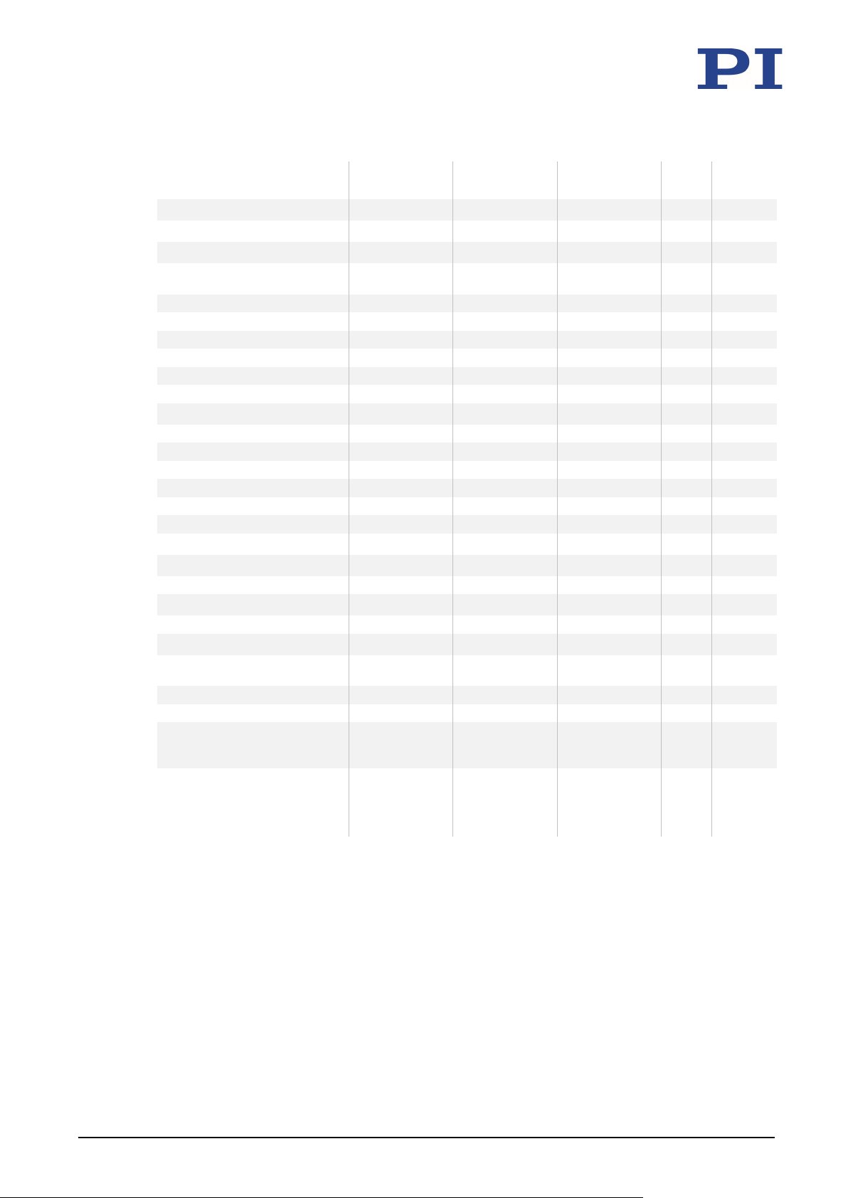
10 Technical Data
Active axes Z Z Z
Motion and positioning
Integrated sensor Capacitive Capacitive Capacitive
Travel range at -20 to 120 V, open loop 65 140 350 µm +20 % /
Travel range, closed loop 50 100 250 µm
Resolution, open loop 0.1 0.2 0.5 nm typ.
Resolution, closed loop 0.2 0.3 1 nm typ.
Linearity error 0.02 0.02 0.02 % typ.
Repeatability ±1 ±1 ±1 nm typ.
Tilt θX, θY <20 <20 <80 µrad typ.
Mechanical properties
Stiffness 0.5 0.6 0.24 N/µm ±20 %
Resonant frequency, no load 1000 790 360 Hz ±20 %
Resonant frequency, under load, 30 g 690 500 270 Hz ±20 %
Push / pull force capacity 10 / 5 10 / 8 10 / 8 N max.
Load capacity 10 10 10 N max.
Lateral load capacity 10 10 10 N max.
Drive properties
Ceramic type PICMA® P-883 PICMA® P-885 PICMA® P-885
Electrical capacitance 0.7 3 6.2 µF ±20 %
Miscellaneous
Operating temperature range -20 to 80 -20 to 80 -20 to 80 °C
Material Aluminum Aluminum Aluminum
Dimensions 30 mm × 30 mm ×
Mass 0.12 0.17 0.24 kg ±5 %
Cable length 1.5 1.5 1.5 m ±10 mm
Sensor / voltage connection CD versions: Sub-D
Recommended electronics E-503, E-505, E-610,
Versions without sensor are available under the order numbers P-62x.Z0L; operating temperature range -20 to 150°C.
P-620.ZCD /
P-620.ZCL
15 mm
7W2 (m)
CL versions: LEMO
E-621, E-625, E-665,
E-709,
E-709.1CC885,
E-754
P-621.ZCD /
P-621.ZCL
40 mm × 40 mm ×
17.5 mm
CD versions: Sub-D
7W2 (m)
CL versions: LEMO
E-503, E-505, E-610,
E-621, E-625, E-665,
E-709,
E-709.1CC885,
E-754
P-622.ZCD /
P-622.ZCL
50 mm × 50 mm ×
17.5 mm
CD versions: Sub-D
7W2 (m)
CL versions: LEMO
E-503, E-505, E-610,
E-621, E-625, E-665,
E-709,
E-709.1CC885,
E-754
Unit Tolerance
-0 %
44 Version: 1.1.0 PZ234E P-62x Positioning Systems
Page 49
10 Technical Data
P-625.1xx
-20 to +120 V
72 Hz
10 W
P-628.1xx
-20 to +120 V
42 Hz
18 W
P-621.2x(x)
-20 to +120 V
178 Hz (in X and Y)
6 W (in X and Y)
P-622.2x(x)
-20 to +120 V
100 Hz (in X and Y)
7 W (in X and Y)
P-629.2xx
-20 to +120 V
33 Hz (in X and Y)
38 W (in X and Y)
P-620.Zxx
-20 to +120 V
333 Hz
5 W
10.1.2 Materials Used for Vacuum-Compatible Models
The following vacuum-compatible materials were used for the .1U and .2U vacuum versions of
the P-62x:
Stainless steel, aluminum, AI
Bakeout temperature: 130 °C
For more information, contact our customer service department (p. 39).
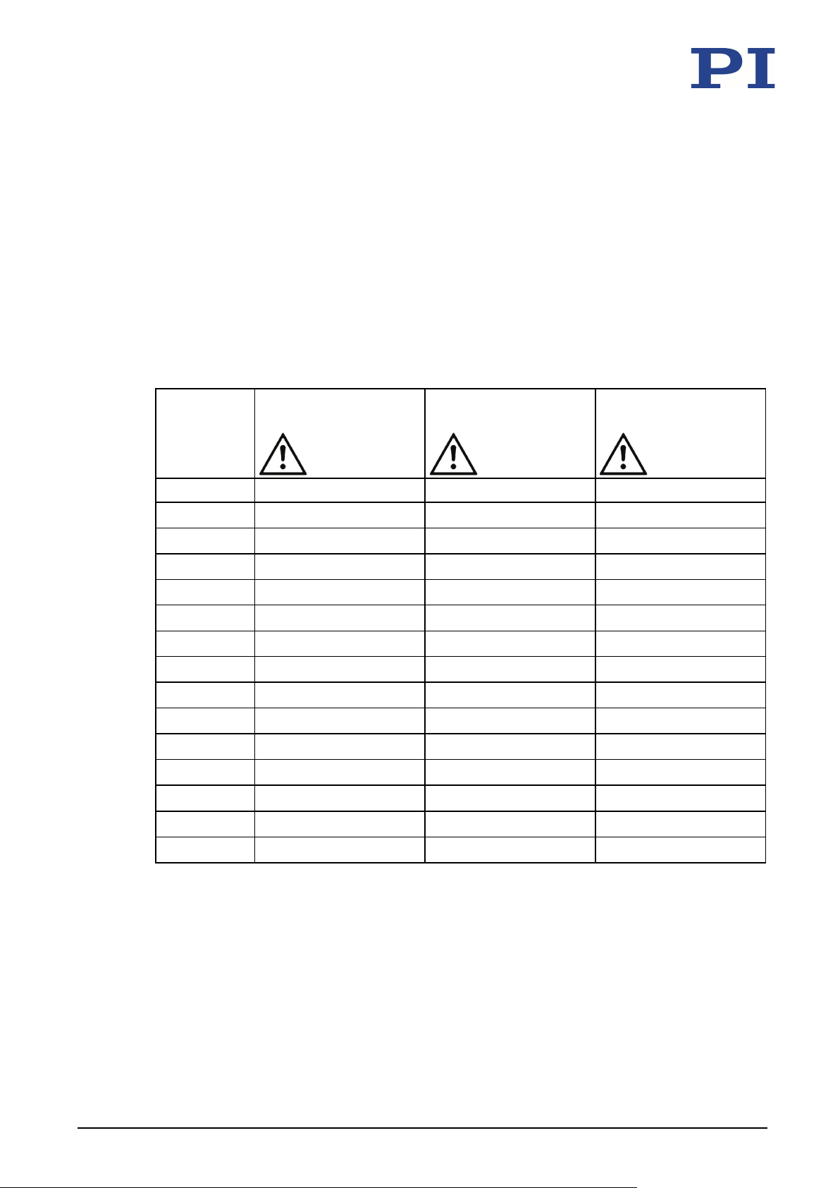
10.1.3 Maximum Ratings
P-62x positioners are designed for the following operating data:
Positioner Maximum operating
voltage
P-620.1xx -20 to +120 V 367 Hz 3 W
P-621.1x(x) -20 to +120 V 267 Hz 9 W
P-622.1x(x) -20 to +120 V 133 Hz 9 W
P-629.1xx -20 to +120 V 42 Hz 49 W
P-620.2xx -20 to +120 V 267 Hz (in X and Y) 2 W (in X and Y)
, titanium, piezoceramic, FEP, PEEK
2O3
Maximum operating
frequency (no load)
Maximum power
consumption
P-62x Positioning Systems PZ234E Version: 1.1.0 45
P-625.2xx -20 to +120 V 65 Hz (in X and Y) 9 W (in X and Y)
P-628.2xx -20 to +120 V 35 Hz (in X and Y) 15 W (in X and Y)
P-621.Zxx -20 to +120 V 263 Hz 18 W
P-622.Zxx -20 to +120 V 120 Hz 17 W
Page 50
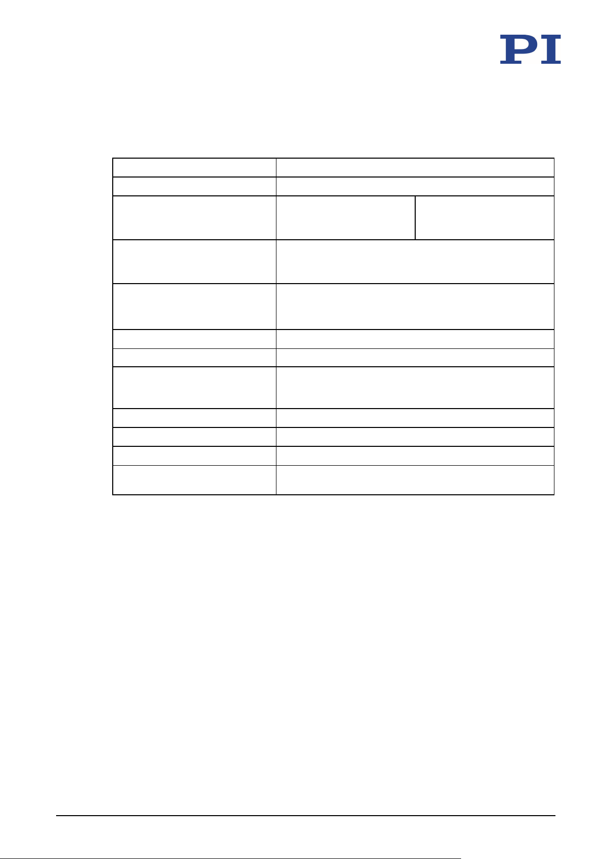
10 Technical Data
Maximum altitude
2000 m
Transport temperature
-25 °C to 85 °C
Maximum bakeout temperature
150 °C
Overvoltage category
II
Degree of pollution
1
10.1.4 Ambient Conditions and Classifications
The following ambient conditions and classifications for the P-62x must be observed:
Area of application For indoor use only
Air pressure All models except vacuum-
compatible models:
Vacuum-compatible models:
-9
1100 hPa to 10
hPa
1100 hPa to 0.1 hPa
Relative humidity Highest relative air humidity 80 % for temperatures to
31 °C
Decreasing linearly to 50 % relative air humidity at 40 °C
Operating temperature -20 °C to 80 °C
For versions without sensor (P-62x.x0L):
-20 °C to 150 °C
Storage temperature -20 °C to 80 °C
(vacuum-compatible products
only)
Protection class I
Degree of protection according to
IP20
IEC 60529
46 Version: 1.1.0 PZ234E P-62x Positioning Systems
Page 51
10 Technical Data
P-620.1xx
30
12
24
15
12
15
18
19
24
15
P-621.1x(x)
40
15
30
20
14
18
24
26
26
20
P-629.1xx
100
22.5
90
60
40
60
84
82
82
60
P-625.1xx
1.51
2.5
M2.5
5
5.5 5 3 6 3.2
P-628.1xx
1.51
2.5
M2.5
5
5.5 5 3 6 3.2
P-629.1xx
2.01
3.5
M2.5
3
10
7.5 4 8
4.3
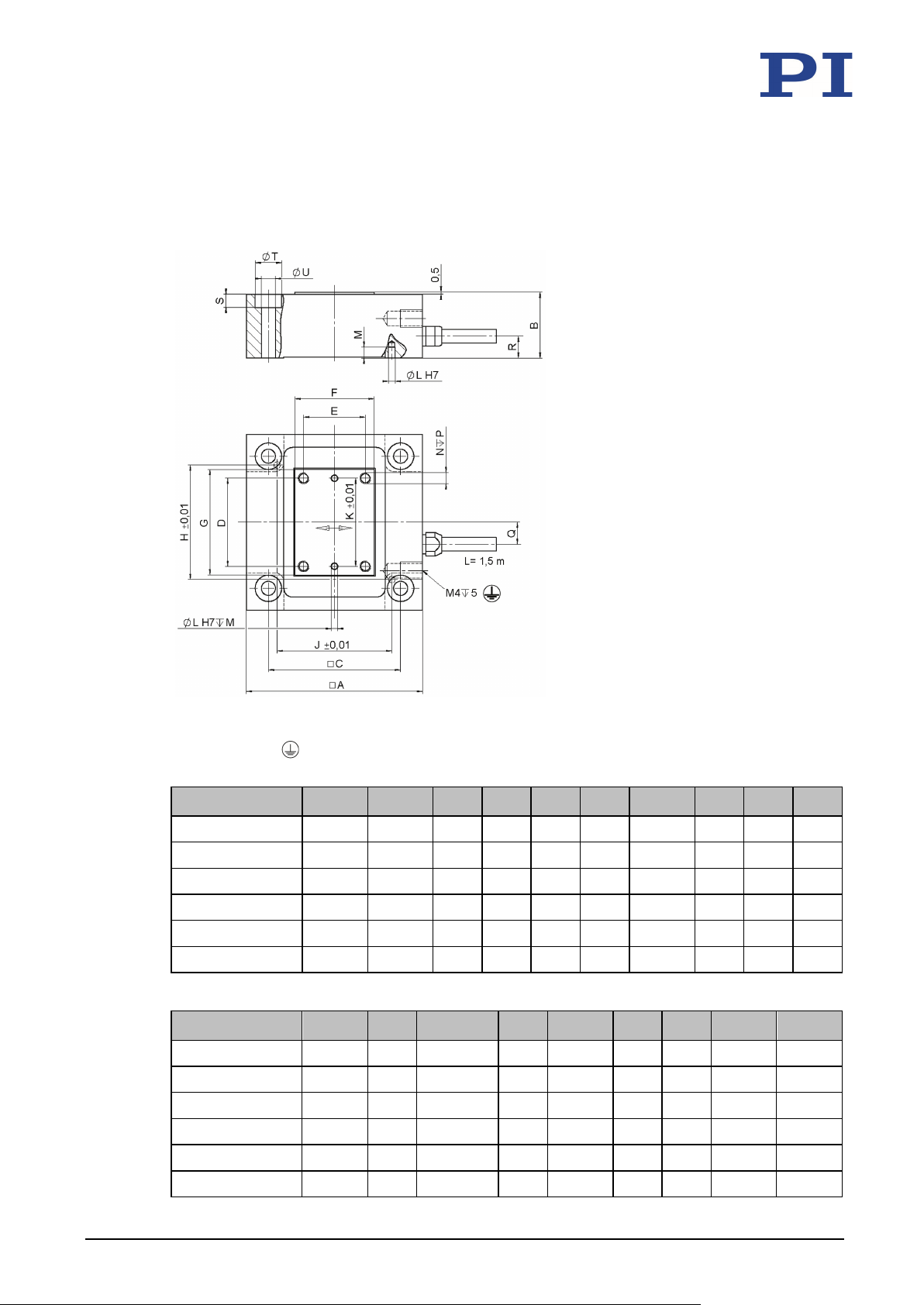
10.2 Dimensions
Dimensions in mm. Note that the decimal places are separated by a comma in the drawings.
Figure 12: P-62x.1CD / .1CL / .10L / .1U
The P-620 does not have a separate protective earth connection.
A B C D i F G H J K
P-622.1x(x) 50 15 40 24 20 25 30 35 35 24
P-625.1xx 60 15 50 40 27 32 44.5 46 46 40
P-628.1xx 80 17 70 58 41 45 63 66 66 58
Ø L M N P Q R S Ø T Ø U
P-620.1xx 1.01 1.5 M2 4 4.5 6 2 4.4 2.2
P-621.1x(x) 1.51 2.5 M2.5 5 5 5 3 6 3.2
P-622.1x(x) 1.51 2.5 M2.5 5 5.5 5 3 6 3.2
P-62x Positioning Systems PZ234E Version: 1.1.0 47
Page 52
10 Technical Data
P-620.2xx
30
21.5
24
24
19
1.01
1.5
M2
3.5
5.1
2.2 9 6
P-621.2x(x)
40
25
30
26
26
1.51
2.5
M3 5 6.25
3.2
10
5
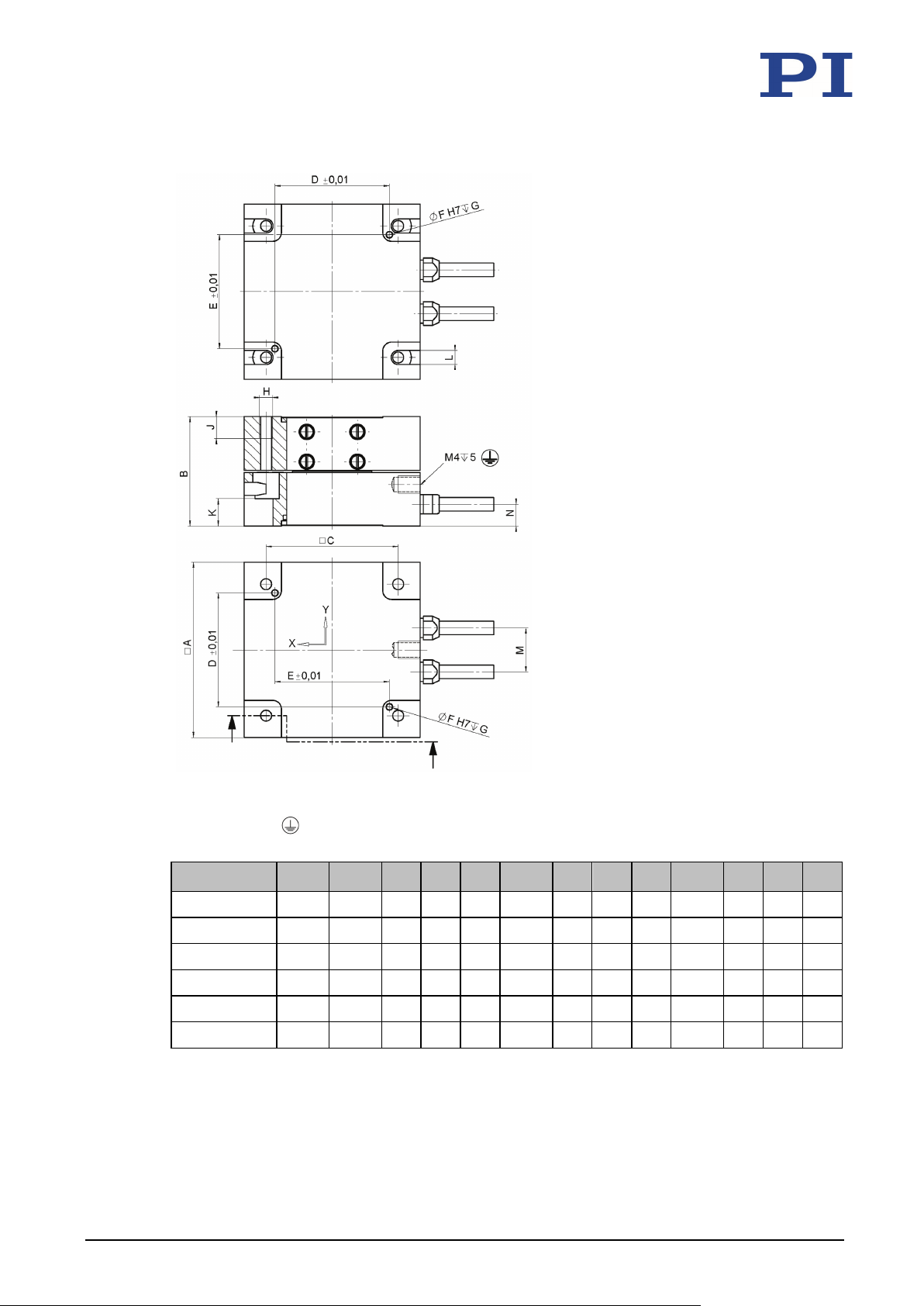
Figure 13: P-62x.2CD / .2CL / .20L / .2U
The P-620 and the P-621.2xx/.2U do not have a separate protective earth connection.
A B C D i Ø F G H J K L M N
P-622.2x(x) 50 25 40 35 35 1.51 2.5 M3 5 6.25 3.2 11 5
P-625.2xx 60 25 50 46 46 1.51 2.5 M3 6 6.25 3.2 11 5
P-628.2xx 80 30 70 66 66 1.51 2.5 M3 6 6.75 3.2 11 5
P-629.2xx 100 40 90 82 82 2.01 3.5 M4 7 9.75 4.3 16 7.5
48 Version: 1.1.0 PZ234E P-62x Positioning Systems
Page 53
10 Technical Data
P-620.Zxx
30
15
24
19
24
1.01
2
M2
28 5 2.2
4.5
6
P-621.Zxx
40
17.5
30
26
26
1.51
2.5
M3
36.5
6.5
3.2 5 5
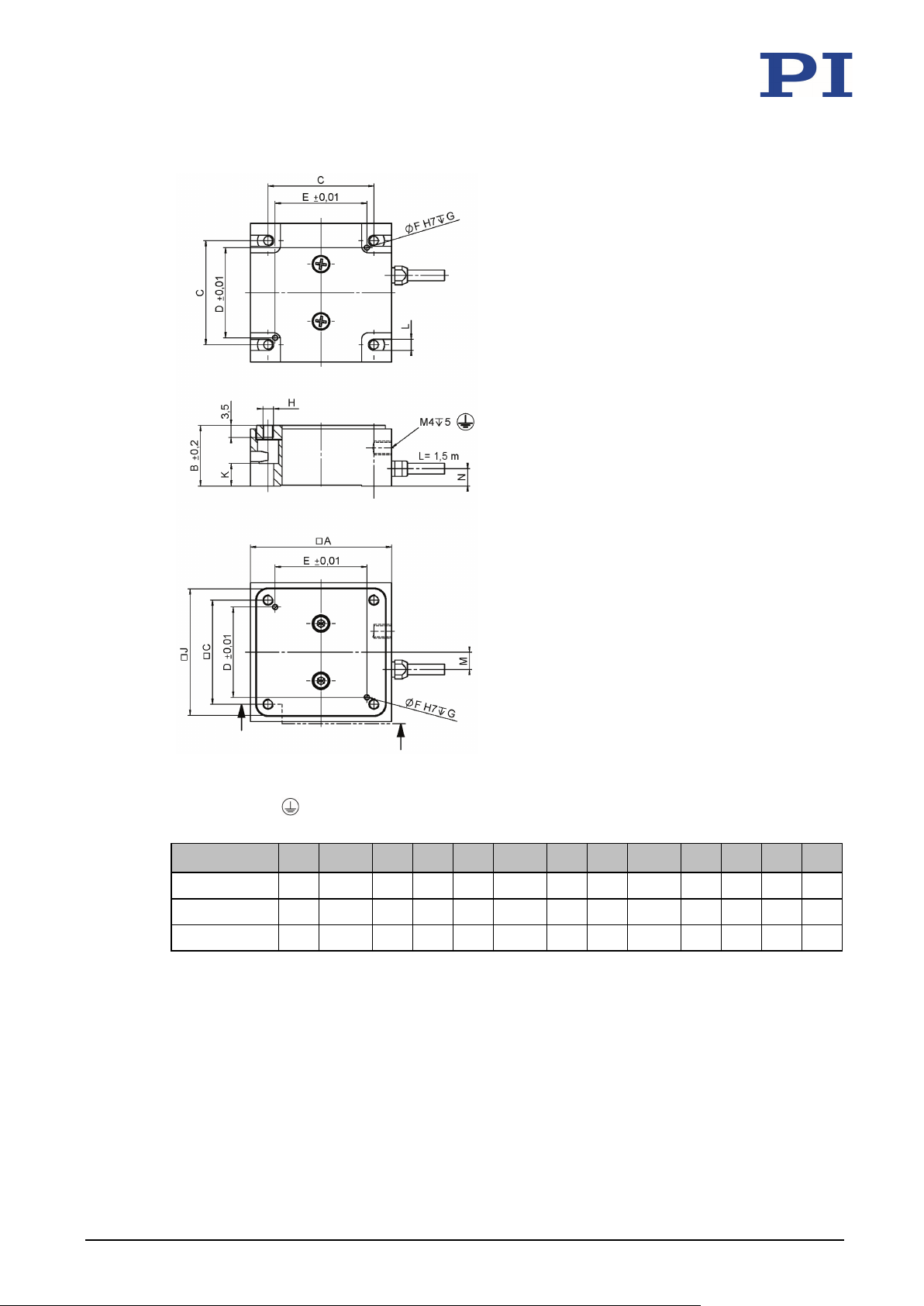
Figure 14: P-62x.ZCD / .ZCL / .Z0L
The P-620 does not have a separate protective earth connection.
A B C D i Ø F G H J K L M N
P-622.Zxx 50 17.5 40 35 35 1.51 2.5 M3 46.5 6.5 3.2 5 5
P-62x Positioning Systems PZ234E Version: 1.1.0 49
Page 54
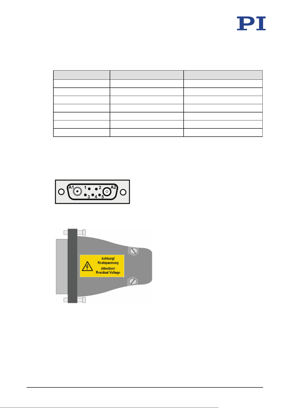
10 Technical Data
M3
0.8 Nm
1.1 Nm
M2.5
0.3 Nm
0.4 Nm
10.3 Torque for Stainless Steel Screws (A2-70)
Screw size Minimum torque Maximum torque
M6 4 Nm 6 Nm
M5 2.5 Nm 3.5 Nm
M4 1.5 Nm 2.5 Nm
M2 0.15 Nm 0.2 Nm
M1.6 0.06 Nm 0.12 Nm
10.4 Pin Assignment
Sub-D 7W2 connector (m)
Figure 15: Sub-D 7W2 connector (m): Front with connections
50 Version: 1.1.0 PZ234E P-62x Positioning Systems
Figure 16: Sub-D connector: Example top view
Page 55
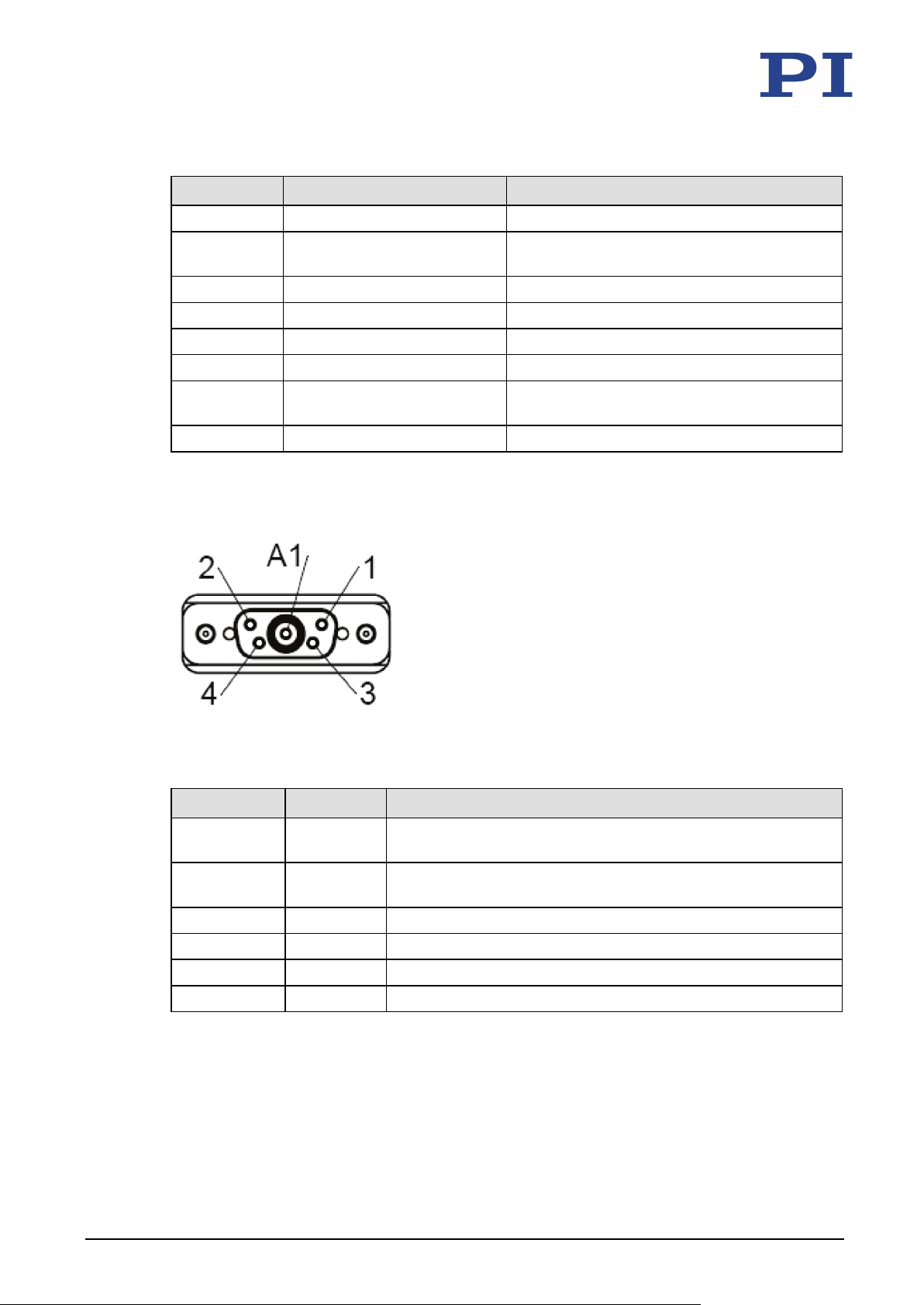
10 Technical Data
A1
PZT
Piezo voltage
A2
Probe
Probe sensor signal (nonmoving part of the
Housing
---
Shield
A1 inner
Probe
Probe sensor signal (nonmoving part of the capacitive sensor)
A1 outer
GND probe
Probe sensor signal shield
1
Target
Target sensor signal (movable part of the capacitive sensor)
Pin Signal Function
capacitive sensor)
1 Data ID chip Data line for ID chip
2 GND target and ID chip Ground of target and ID chip
3 GND PZT Piezo voltage ground
4 --- (Not connected)
5 Target Target sensor signal (movable part of the
capacitive sensor)
Sub-D connector 5W1 (f)
Figure 17: Sub-D connector 5W1 (f): Front side with connections
Pin Signal Function
conductor
conductor
2 PZT+ Piezo voltage+
3 GND Target Target sensor signal shield
4 PZT– Piezo voltage–
P-62x Positioning Systems PZ234E Version: 1.1.0 51
Page 56
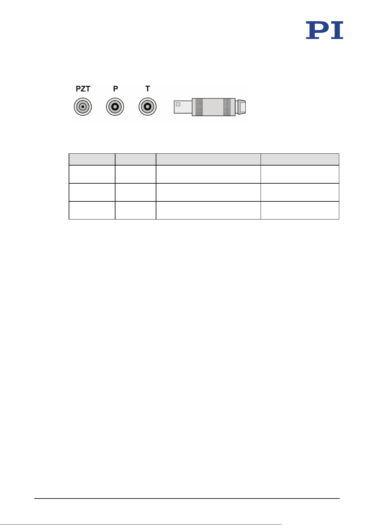
10 Technical Data
LEMO coaxial connectors
Figure 18: LEMO connectors: PZT, P and T
Connector Signal Function Connector shell
P Probe Probe sensor signal (nonmoving
Cable shield
part of the capacitive sensor)
T Target Target sensor signal (movable part
Cable shield
of the capacitive sensor)
PZT PZT Piezo voltage Piezo voltage ground on
cable shield
52 Version: 1.1.0 PZ234E P-62x Positioning Systems
Page 57
11 Old Equipment Disposal
11
Old Equipment Disposal
In accordance with EU law, electrical and electronic equipment may not be disposed of in EU
member states via the municipal residual waste.
Dispose of your old equipment according to international, national, and local rules and
regulations.
In order to fulfil its responsibility as the product manufacturer, Physik Instrumente (PI) GmbH &
Co. KG undertakes environmentally correct disposal of all old PI equipment made available on
the market after 13 August 2005 without charge.
Any old PI equipment can be sent free of charge to the following address:
Physik Instrumente (PI) GmbH & Co. KG
Auf der Roemerstr. 1
D-76228 Karlsruhe, Germany
P-62x Positioning Systems PZ234E Version: 1.1.0 53
Page 58

Page 59
12 EU Declaration of Conformity
12
EU Declaration of Conformity
For the P-62x, an EU Declaration of Conformity has been issued in accordance with the
following European directives:
Low Voltage Directive
EMC Directive
RoHS Directive
The applied standards certifying the conformity are listed below.
Safety (Low Voltage Directive): EN 61010-1
EMC: EN 61326-1
RoHS: EN 50581
P-62x Positioning Systems PZ234E Version: 1.1.0 55
 Loading...