

Page 1
User Manual
Physik Instrumente (PI) GmbH & Co. KG, Auf der Roemerstrasse 1, 76228 Karlsruhe, Germany
Phone +49 721 4846
motor, 10 mm
MP40E, version 1.2.0, valid for M-227.10, M-227.25, M-227.50
CBo, 5/20/2019
M-227
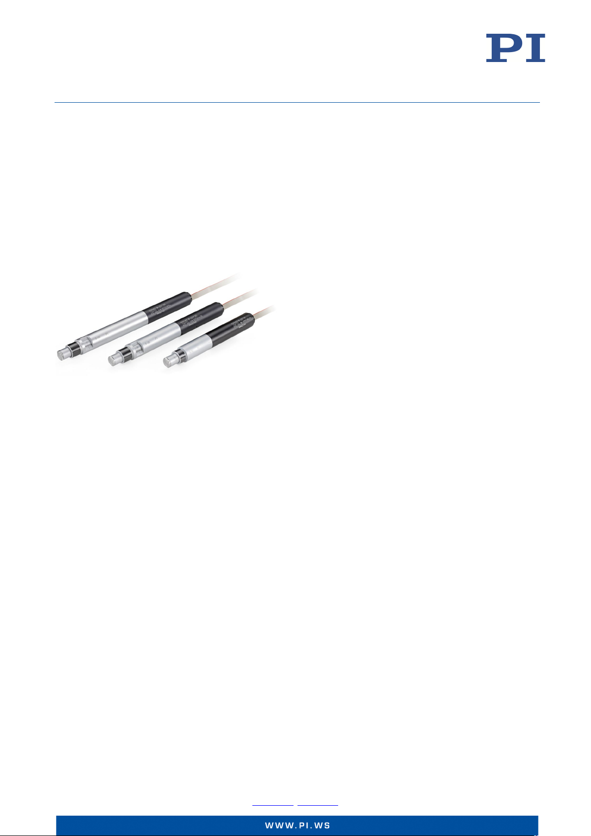
High-resolution linear actuator with DC motor
With optional piezo actuator
This document describes the following products:
M-227.50
M-227.25
M-227.10
High-resolution linear actuator with DC
motor, 50 mm
High-resolution linear actuator with DC
motor, 25 mm
High-resolution linear actuator with DC
Page 2

User Manual
Physik Instrumente (PI) GmbH & Co. KG, Auf der Roemerstrasse 1, 76228 Karlsruhe, Germany Page 2 / 26
Phone +49 721 4846
MP40E, version 1.2.0, valid for M-227.10, M-227.25, M-227.50
CBo, 5/20/2019
Contents
About this Document 4
Explanation of Symbols ....................................................................................................................................... 4
Typographic Conventions ................................................................................................................................................ 4
Symbols Used .................................................................................................................................................................. 4
Other Applicable Documents .............................................................................................................................. 5
Downloading Manuals ......................................................................................................................................... 5
Safety 6
Intended Use ....................................................................................................................................................... 6
Safety Precautions ............................................................................................................................................... 7
Mechanical Dangers ........................................................................................................................................................ 7
Electrical Dangers ............................................................................................................................................................ 8
Thermal Dangers ............................................................................................................................................................. 8
Product Description 8
Model Overview .................................................................................................................................................. 8
Product View ....................................................................................................................................................... 9
Directions of Motion ........................................................................................................................................... 9
Product Labeling ................................................................................................................................................ 10
Scope of Delivery ............................................................................................................................................... 10
Suitable Electronics ........................................................................................................................................... 10
Accessories ........................................................................................................................................................ 11
Optional Piezo Actuator ................................................................................................................................................ 11
Optional Tips ................................................................................................................................................................. 11
Technical Features ............................................................................................................................................. 11
Rotary Encoder .............................................................................................................................................................. 11
Unpacking 11
Installation 12
Installing the M-227 .......................................................................................................................................... 12
Replacing the Standard Flat Tip (Optional) ....................................................................................................... 13
Connecting the M-227 to the Electronics .......................................................................................................... 13
Startup and Operation 14
General Notes on Startup and Operation ......................................................................................................... 14
Operating Parameters ....................................................................................................................................... 15
Starting and Operating the M-227 .................................................................................................................... 16
Maintenance 16
Cleaning the M-227 ........................................................................................................................................... 16
-0, Fax +49 721 4846-1019, Email [email protected], www.pi.ws
Page 3

User Manual
Physik Instrumente (PI) GmbH & Co. KG, Auf der Roemerstrasse 1, 76228 Karlsruhe, Germany Page 3 / 26
Phone +49 721 4846
MP40E, version 1.2.0, valid for M-227.10, M-227.25, M-227.50
CBo, 5/20/2019
Troubleshooting 17
General Notes on Troubleshooting ................................................................................................................... 17
Actuator Got Stuck at the Hard Stop ................................................................................................................. 17
Unblocking the Actuator Electrically ............................................................................................................................. 17
Unblocking the Actuator by Hand ................................................................................................................................. 18
Coupling of the Actuator Slips ........................................................................................................................... 19
Retightening the Coupling ............................................................................................................................................ 19
Customer Service 19
Technical Data 20
Specifications ..................................................................................................................................................... 20
Maximum Ratings .............................................................................................................................................. 21
Ambient Conditions and Classifications ............................................................................................................ 21
Dimensions ........................................................................................................................................................ 22
Dimensions of the M-227 .............................................................................................................................................. 22
Dimensions of the P-885.20 Piezo Actuator ................................................................................................................. 23
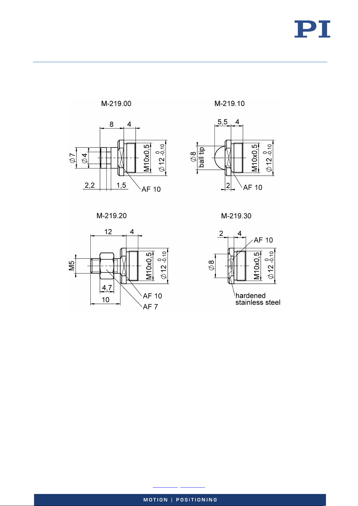
Dimensions of the M-219 Tips ...................................................................................................................................... 24
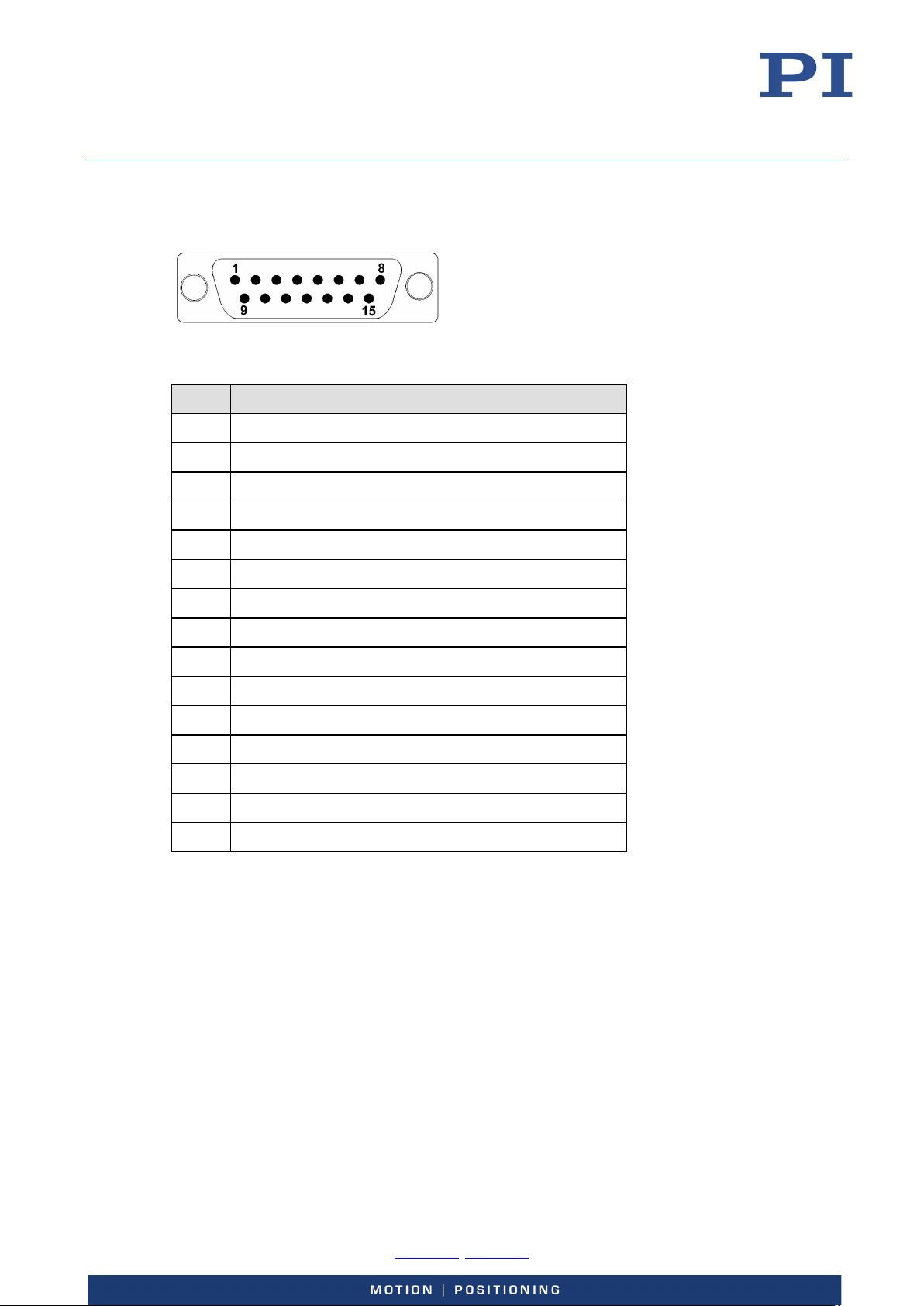
Pin Assignment .................................................................................................................................................. 25
Old Equipment Disposal 26
-0, Fax +49 721 4846-1019, Email [email protected], www.pi.ws
Page 4
User Manual
Physik Instrumente (PI) GmbH & Co. KG, Auf der Roemerstrasse 1, 76228 Karlsruhe, Germany Page 4 / 26
Phone +49 721 4846
MP40E, version 1.2.0, valid for M-227.10, M-227.25, M-227.50
CBo, 5/20/2019
About this Document
This user manual contains information necessary for the intended use of the M-227.
It assumes that the reader has a fundamental understanding of basic servo systems as well as
motion control concepts and applicable safety procedures.
Explanation of Symbols
This section explains the symbols and markings used by PI in this document.
Typographic Conventions
Symbol Meaning
1.
2.
Action consisting of one or several steps whose sequential order is irrelevant
p. 5 Cross-reference to page 5
Symbols Used
CAUTION
Dangerous situation
Failure to comply could lead to minor injury.
Precautionary measures for avoiding.
NOTICE
Dangerous situation
Failure to comply could cause damage to equipment.
Precautionary measures for avoiding.
Action consisting of several steps whose sequential order must be observed
List item
INFORMATION
Additional information that can affect your application.
Symbol / Label Meaning
Warning sign on the product that refers to detailed information in the
documentation.
-0, Fax +49 721 4846-1019, Email [email protected], www.pi.ws
Page 5
User Manual
Physik Instrumente (PI) GmbH & Co. KG, Auf der Roemerstrasse 1, 76228 Karlsruhe, Germany Page 5 / 26
Phone +49 721 4846
MP40E, version 1.2.0, valid for M-227.10, M-227.25, M-227.50
CBo, 5/20/2019
Other Applicable Documents
Product Document
M-168 / M-22x / M-23x linear actuators MP122EK short instructions
Downloading Manuals
INFORMATION
If a manual is missing or problems occur with downloading:
Contact our customer service department (p. 19).
INFORMATION
For products that are supplied with software (CD in the scope of delivery), access to the
manuals is protected by a password. Protected content is only displayed on the website after
entering the access data.
You need the product CD to get the access data.
For products with CD: Get access data
1. Insert the product CD into the PC drive.
2. Switch to the Manuals directory on the CD.
3. In the Manuals directory, open the Release News (file including releasenews in the file
name).
4. Get the access data for downloading protected content in the "User login for software
download" section of the Release News. Possible methods for getting the access data:
− Link to a page for registering and requesting the access data
− User name and password is specified
5. If the access data needs to be requested via a registration page:
a) Follow the link in the Release News.
b) Enter the required information in the browser window.
c) Click Show login data in the browser window.
d) Note the user name and password shown in the browser window.
Downloading manuals
If you have requested access data for protected contents via a registration page (see above):
Click the links in the browser window to change to the content for your product and log
in using the access data that you received.
-0, Fax +49 721 4846-1019, Email [email protected], www.pi.ws
Page 6

User Manual
Physik Instrumente (PI) GmbH & Co. KG, Auf der Roemerstrasse 1, 76228 Karlsruhe, Germany Page 6 / 26
Phone +49 721 4846
MP40E, version 1.2.0, valid for M-227.10, M-227.25, M-227.50
CBo, 5/20/2019
General procedure:
Safety
1. Open the website www.pi.ws
2. If access to the manuals is protected by a password:
a) Click Login.
b) Log in with the user name and password.
3. Click Search.
4. Enter the product number up to the period (e.g., M-227) or the product family (e.g.,
linear actuator with DC motor) into the search field.
5. Click Start search or press the Enter key.
6. Open the corresponding product detail page in the list of search results:
a) If necessary: Scroll down the list.
b) If necessary: Click Load more results at the bottom of the list.
c) Click the corresponding product in the list.
7. Click the Downloads tab.
The manuals are shown under Documentation.
8. Click the desired manual and save it to the hard disk of your PC or to a data storage
medium.
.
Intended Use
The M-227 linear actuator is a laboratory device as defined by DIN EN 61010-1. It is intended to
be used in interior spaces and in an environment which is free of dirt, oil and lubricants.
Based on its design and realization, the M-227 is intended for single-axis positioning, adjusting
and shifting of loads at different velocities. The M-227 is not intended for high duty cycles and
applications in areas in which a failure would present severe risks to human beings or the
environment.
The intended use of the M-227 is only possible when completely mounted and connected and
only in conjunction with suitable electronics (p. 10) that provide the required operating
voltages. To ensure proper performance of the servo-control system, the electronics must also
be able to read out and process the signals from the rotary encoder.
The M-227 may only be started up, operated, maintained and cleaned by authorized and
qualified staff.
-0, Fax +49 721 4846-1019, Email [email protected], www.pi.ws
Page 7
User Manual
Physik Instrumente (PI) GmbH & Co. KG, Auf der Roemerstrasse 1, 76228 Karlsruhe, Germany Page 7 / 26
Phone +49 721 4846
MP40E, version 1.2.0, valid for M-227.10, M-227.25, M-227.50
CBo, 5/20/2019
Safety Precautions
Mechanical Dangers
CAUTION
Risk of crushing!
Risk of minor injuries or damage to equipment from crushing between the pusher and a fixed
part or obstacle.
Use protective structures to keep limbs away from areas in which they could be seized by
moving parts.
Maintain safety distances according to DIN EN ISO 13857.
Mount the M-227 so that the motion of the pusher is not hindered by objects in the
workspace.
NOTICE
Damage due to excessive torque on the pusher!
Excessive torque on the pusher (e.g., when the tip is replaced) can damage the M-227.
Do not exceed a torque of 1 Nm on the pusher.
NOTICE
Increased friction from lateral forces on the pusher!
Lateral forces acting on the pusher impair the motion of the pusher and increase wear on the
drive components.
Avoid lateral forces on the pusher of the M-227.
NOTICE
Damage from wrong clamping or clamping too tightly!
Wrong clamping or clamping too tightly can damage the M-227.
Do not clamp the M-227 on the motor housing (p. 9).
Do not clamp the M-227 too tightly.
NOTICE
Cable break due to excessively bent or crushed cable!
A cable break leads to failure of the M-227.
Install the M-227 so that the cable cannot be bent too strongly or crushed during
operation.
-0, Fax +49 721 4846-1019, Email [email protected], www.pi.ws
Page 8
User Manual
Physik Instrumente (PI) GmbH & Co. KG, Auf der Roemerstrasse 1, 76228 Karlsruhe, Germany Page 8 / 26
Phone +49 721 4846
MP40E, version 1.2.0, valid for M-227.10, M-227.25, M-227.50
CBo, 5/20/2019
Electrical Dangers
NOTICE
Operating voltage too high or incorrectly connected!
Operating voltages that are too high or incorrectly connected can cause damage to the M-227.
Only operate the M-227 with electronics and original accessories from PI.
Do not exceed the operating voltage range (p. 21) for which the M-227 is specified.
Operate the M-227 only when the operating voltage is properly connected; see "Pin
Assignment" (p. 25).
Thermal Dangers
CAUTION
Risk of burning!
The M-227 can overheat in continuous operation with high load. Touching an overheated
M-227 can cause slight injuries from burning. In addition, overheating can damage the M-227.
To prevent overheating, do not operate the M-227 continuously with high load.
If overheated accidentally:
Do not touch the M-227 until it has cooled off.
Product Description
Model Overview
The following standard versions of the M-227 are available:
Model Description
M-227.10 High-resolution linear actuator with DC motor, 10 mm
M-227.25 High-resolution linear actuator with DC motor, 25 mm
M-227.50 High-resolution linear actuator with DC motor, 50 mm
-0, Fax +49 721 4846-1019, Email [email protected], www.pi.ws
Page 9
User Manual
Physik Instrumente (PI) GmbH & Co. KG, Auf der Roemerstrasse 1, 76228 Karlsruhe, Germany Page 9 / 26
Phone +49 721 4846
MP40E, version 1.2.0, valid for M-227.10, M-227.25, M-227.50
CBo, 5/20/2019
Product View
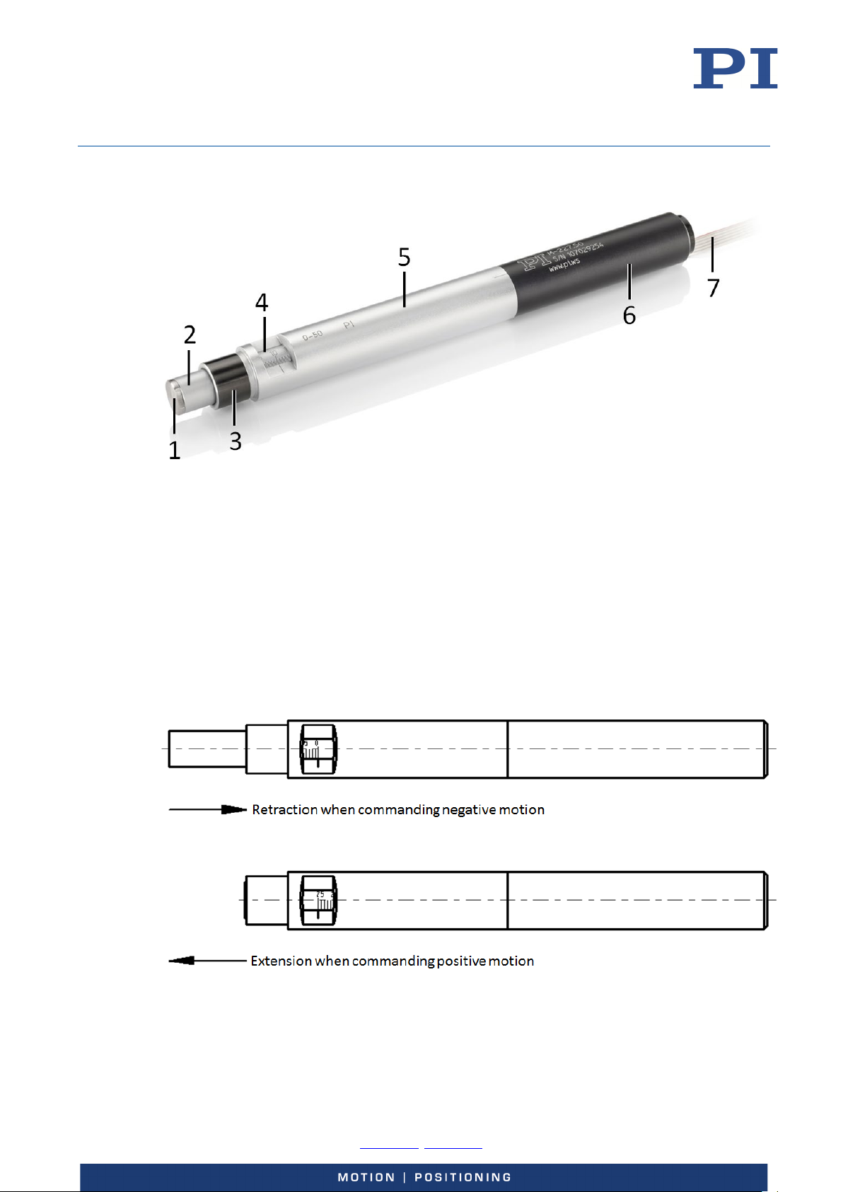
Figure 1: Product view (example view of an M-227.50)
1 Flat tip (non-rotating)
2 Pusher
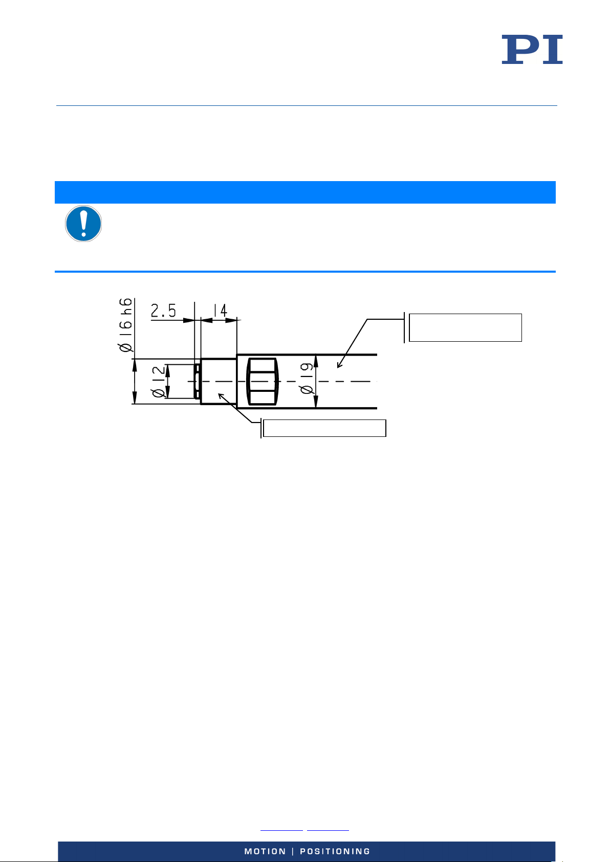
3 Clamping shank, Ø 16 mm
4 Micrometer scale
5 Micrometer housing, Ø 19 mm
6 Motor housing (do not use for clamping)
7 Connecting cable
Directions of Motion
Figure 2: Directions of motion of the M-227
-0, Fax +49 721 4846-1019, Email [email protected], www.pi.ws
Page 10
User Manual
Physik Instrumente (PI) GmbH & Co. KG, Auf der Roemerstrasse 1, 76228 Karlsruhe, Germany Page 10 / 26
Phone +49 721 4846
MP40E, version 1.2.0, valid for M-227.10, M-227.25, M-227.50
CBo, 5/20/2019
Product Labeling
Labeling Description
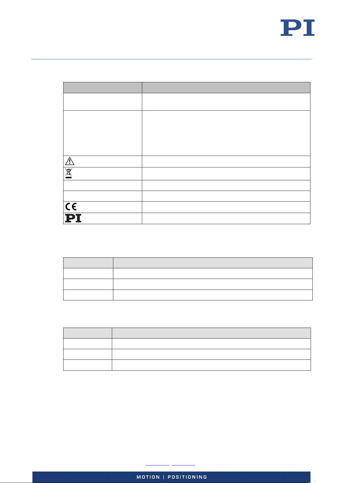
M-227.50 Product number (example), the digits after the period refer to
the model
123456789 Serial number (example), individual for each M-227
Meaning of each position (from the left):
1 = internal information
2 and 3 = year of manufacture
4 to 9 = consecutive numbers
Warning sign "Pay attention to the manual!"
Old equipment disposal (p. 26)
Country of origin: Germany Country of origin
WWW.PI.WS Manufacturer's address (website)
Scope of Delivery
Product number Description
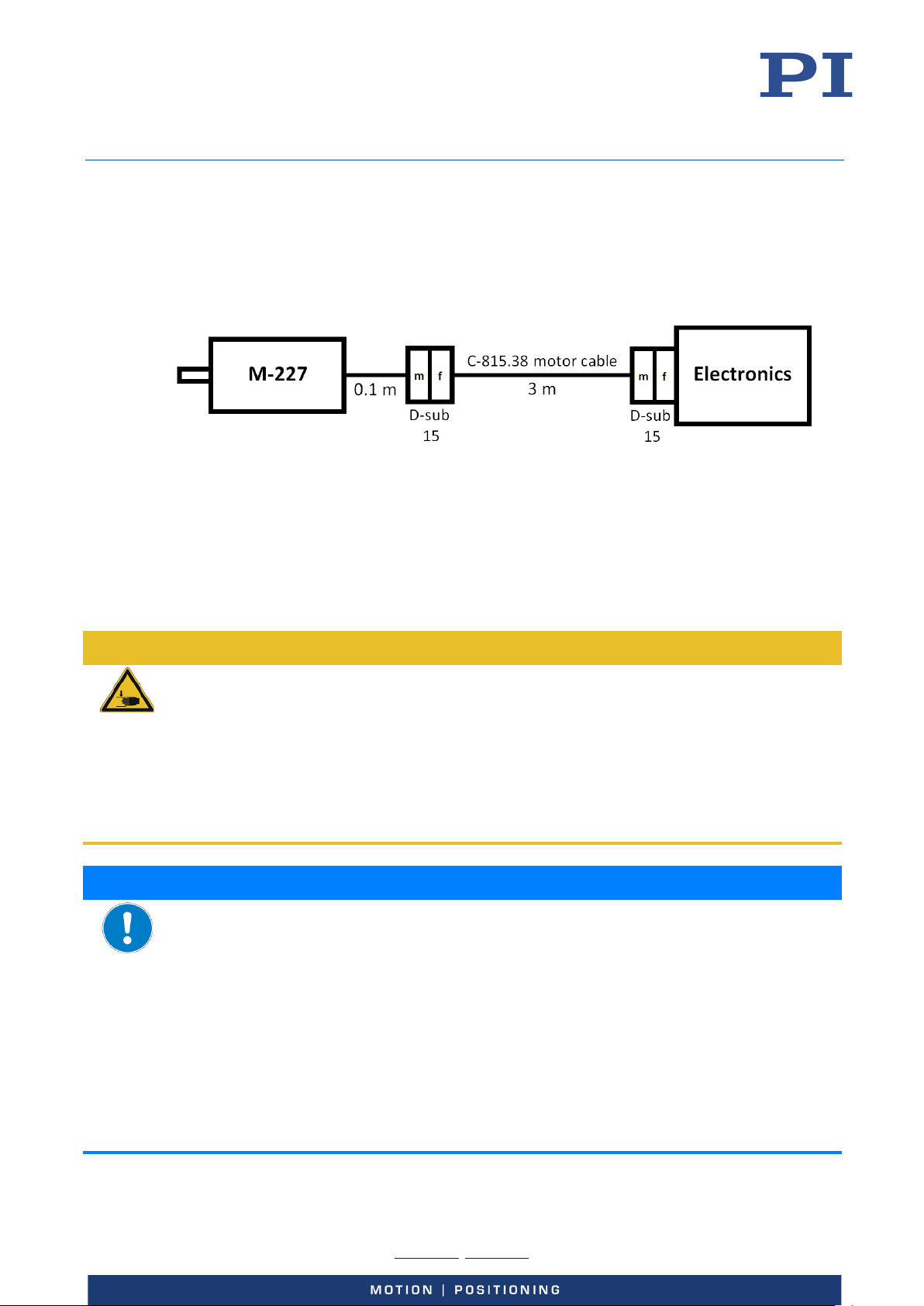
M-227 High-resolution linear actuator with DC motor according to order (p. 8)
C-815.38 Motor cable, 3 m, D-sub, 15-pin (m/f)
MP122EK Short instructions for M-168 / M-22x / M-23x linear actuators
Suitable Electronics
Product number Description
C-863 Mercury servo controller, 1 axis
C-863.20C885 Motion controller module, 2 axes, for C-885 PIMotionMaster
CE conformity mark
Manufacturer's logo
C-884 Motion controller, 4 or 6 axes
To order, contact our customer service department (p. 19).
-0, Fax +49 721 4846-1019, Email [email protected], www.pi.ws
Page 11
User Manual
Physik Instrumente (PI) GmbH & Co. KG, Auf der Roemerstrasse 1, 76228 Karlsruhe, Germany Page 11 / 26
Phone +49 721 4846
MP40E, version 1.2.0, valid for M-227.10, M-227.25, M-227.50
CBo, 5/20/2019
Accessories
Optional Piezo Actuator
Product number Description
P-885.20 Piezo actuator for micrometer screws
To order, contact our customer service department (p. 19).
Optional Tips
Product number Description
M-219.00 Spherical tip, M10 × 0.5 mm
M-219.10 Ball tip, M10 × 0.5 mm
M-219.20 Tip with M5 outer thread, M10 × 0.5 mm
M-219.30 Tip made of hardened steel, M10 × 0.5 mm
To order, contact our customer service department (p. 19).
Technical Features
Rotary Encoder
The M-227 is equipped with a rotary encoder. A rotary encoder, also called an incremental or
incremental rotary encoder, is implemented at a rotating point in the drivetrain, e.g., the motor
shaft. To determine the relative position, the controller counts the encoder signals, the
so-called impulses.
Unpacking
1. Unpack the M-227 with care.
2. Compare the contents with the scope of delivery according to the contract and the
delivery note.
3. Inspect the contents for signs of damage. If any parts are damaged or missing, contact
our customer service department immediately.
4. Keep all packaging materials in case the product needs to be returned.
-0, Fax +49 721 4846-1019, Email [email protected], www.pi.ws
Page 12
User Manual
Physik Instrumente (PI) GmbH & Co. KG, Auf der Roemerstrasse 1, 76228 Karlsruhe, Germany Page 12 / 26
Phone +49 721 4846
Ø 16 mm clamping shank
Ø 19 mm micrometer
MP40E, version 1.2.0, valid for M-227.10, M-227.25, M-227.50
CBo, 5/20/2019
Installation
Installing the M-227
NOTICE
Damage from wrong clamping or clamping too tightly!
Wrong clamping or clamping too tightly can damage the M-227.
Do not clamp the M-227 on the motor housing (p. 9).
Do not clamp the M-227 too tightly.
housing
Figure 3: Clamping surfaces of the M-227
Requirements
You have read and understood the safety precautions (p. 7).
The M-227 is not connected to the electronics.
You have accounted for the space required to route cables without bending and
according to regulations.
Tools and accessories
Suitable holder(s) for clamping the M-227
Installing the M-227
Clamp the M-227 on the clamping surfaces intended for this purpose (see Figure 3
above). Ensure that the clamping is neither too tight nor too loose.
-0, Fax +49 721 4846-1019, Email [email protected], www.pi.ws
Page 13

User Manual
Physik Instrumente (PI) GmbH & Co. KG, Auf der Roemerstrasse 1, 76228 Karlsruhe, Germany Page 13 / 26
Phone +49 721 4846
MP40E, version 1.2.0, valid for M-227.10, M-227.25, M-227.50
CBo, 5/20/2019
Replacing the Standard Flat Tip (Optional)
NOTICE
Damage due to excessive torque on the pusher!
Excessive torque on the pusher (e.g., when the tip is replaced) can damage the M-227.
Do not exceed a torque of 1 Nm on the pusher.
Requirements
You have read and understood the safety precautions (p. 7).
The M-227 is not connected to the electronics.
Tools and accessories
M-219 tip or P-855.20 piezo actuator (p. 11)
AF 10 open-end wrench
AF 13 open-end wrench (only for P-855.20)
Replacing the standard flat tip (optional)
1. Unscrew the standard flat tip from the pusher carefully using an AF 10 open-end
wrench. Do not exceed a torque of 1 Nm when unscrewing.
2. Screw the new tip into the pusher:
Only with the M-219 tip:
a) Screw in the M-219 tip by hand.
b) If necessary, tighten the connection lightly using an AF 10 open-end wrench.
Do not exceed a torque of 1 Nm when tightening.
Only with the P-855.20 piezo actuator:
a) Screw in the P-855.20 piezo actuator by hand.
b) If necessary, tighten the locking ring of the P-855.20 lightly using an AF 13 open-end
wrench. Do not exceed a torque of 1 Nm when tightening.
Connecting the M-227 to the Electronics
Requirements
You have read and understood the safety precautions (p. 7).
You have read and understood the user manual for the electronics.
The electronics are switched off, i.e., not connected to the power source.
Tools and accessories
C-815.38 motor cable (p. 10)
-0, Fax +49 721 4846-1019, Email [email protected], www.pi.ws
Page 14
User Manual
Physik Instrumente (PI) GmbH & Co. KG, Auf der Roemerstrasse 1, 76228 Karlsruhe, Germany Page 14 / 26
Phone +49 721 4846
MP40E, version 1.2.0, valid for M-227.10, M-227.25, M-227.50
CBo, 5/20/2019
Connecting the M-227 to the electronics
Connect the M-227, the motor cable and the electronics as shown in the connection
diagram below.
− Pay attention to the assignment that is given by the labeling on the sockets,
connectors and cables.
Figure 4: Connection of the M-227 to the electronics
Startup and Operation
General Notes on Startup and Operation
NOTICE
CAUTION
Risk of crushing!
Risk of minor injuries or damage to equipment from crushing between the pusher and a fixed
part or obstacle.
Use protective structures to keep limbs away from areas in which they could be seized by
moving parts.
Maintain safety distances according to DIN EN ISO 13857.
Mount the M-227 so that the motion of the pusher is not hindered by objects in the
workspace.
Collision with the hard stop or an obstacle!
Collision with the hard stop or an obstacle leads to damage or considerable wear on the
M-227.
Do not place any objects in areas where they can get caught by moving parts.
If the pusher or the load mounted on it collides with an obstacle, switch off the motor.
Only command target positions that are located within the travel range.
Use external limit switches to avoid collisions.
Stop the motion immediately if a controller malfunction occurs.
Ensure that the M-227 does neither abruptly stop at the end of the travel range nor
attempt to continue moving.
Ensure that the end of the travel range is approached at low velocity.
Determine the maximum velocity for your application.
-0, Fax +49 721 4846-1019, Email [email protected], www.pi.ws
Page 15
User Manual
Physik Instrumente (PI) GmbH & Co. KG, Auf der Roemerstrasse 1, 76228 Karlsruhe, Germany Page 15 / 26
Phone +49 721 4846
MP40E, version 1.2.0, valid for M-227.10, M-227.25, M-227.50
CBo, 5/20/2019
NOTICE
Unintentional motion!
Unintentional motion of the M-227 is possible when connecting it to the controller.
Before connecting the M-227, check whether a macro is defined as the startup macro in
the controller and cancel the selection if necessary.
INFORMATION
Unsuitable settings made to the servo control parameters can impair the performance of the
M-227. The consequences of this can be expressed as follows:
Oscillation
Imprecise approach of the position
Settling time is too long
If the performance of the M-227 is not satisfactory, check the settings for the servo control
parameters of your controller.
Use the default parameters for the first startup only.
INFORMATION
Due to its compact design, the M-227 does not have internal limit switches. Without limit
switches, the M-227 must be stopped manually to avoid collision with the hard stop.
Therefore, we strongly recommend using external limit switches. Note that all PI motor
controllers support limit switches.
INFORMATION
If the programmed velocity is too high, accelerating and decelerating ramps will not be
performed as programmed, and the physical velocity will be lower than the profile velocity.
When this happens the trajectory generator may have already completed its move while the
actuator is still trying to catch up.
Operating Parameters
If you use the software from the scope of delivery of the electronics (p. 10), the operating
parameters can be loaded from the positioner database. The records in the positioner database
are updated regularly.
Install the PI Update Finder from the product CD for the electronics onto your PC and
update the positioner database on your PC.
Further information can be found in the user manual for the electronics (p. 10).
-0, Fax +49 721 4846-1019, Email [email protected], www.pi.ws
Page 16
User Manual
Physik Instrumente (PI) GmbH & Co. KG, Auf der Roemerstrasse 1, 76228 Karlsruhe, Germany Page 16 / 26
Phone +49 721 4846
MP40E, version 1.2.0, valid for M-227.10, M-227.25, M-227.50
CBo, 5/20/2019
Starting and Operating the M-227
Requirements
You have read and understood the safety precautions (p. 7).
You have read and understood the general notes on startup and operation (p. 14).
You have read and understood the user manual for the electronics (p. 10).
You have read and understood the user manual for the PC software.
You have installed (p. 12) the M-227 correctly.
The electronics and the required PC software were installed. All connections to the
electronics were made (see user manual for the electronics).
Starting and operating the M-227
Follow the instructions in the user manual for the electronics (p. 10) used for startup
and operation of the M-227.
Maintenance
NOTICE
Damage due to improper maintenance!
The M-227 can become misaligned as a result of improper maintenance.
Loosen any screws only when instructed in this user manual.
Cleaning the M-227
INFORMATION
Frequent motion over a limited travel range can cause the lubricant to be distributed unevenly
on the drive screw.
Perform a maintenance run over the entire travel range at regular intervals (see user
manual for the controller). The more motion is done over a limited travel range, the
shorter the time must be between the maintenance runs.
Requirements
You have disconnected the M-227 from the electronics.
Cleaning the M-227
Clean the surfaces of the M-227 with a cloth that is dampened with a mild cleanser or
disinfectant (e.g., isopropyl alcohol).
-0, Fax +49 721 4846-1019, Email [email protected], www.pi.ws
Page 17
User Manual
Physik Instrumente (PI) GmbH & Co. KG, Auf der Roemerstrasse 1, 76228 Karlsruhe, Germany Page 17 / 26
Phone +49 721 4846
MP40E, version 1.2.0, valid for M-227.10, M-227.25, M-227.50
CBo, 5/20/2019
Troubleshooting
General Notes on Troubleshooting
NOTICE
Damage due to mechanical overload of the bellows coupling!
The bellows coupling of the actuator is a sensitive part that can be damaged if handled
improperly.
Avoid bending forces on the bellows coupling.
Avoid pull forces on the bellows coupling.
INFORMATION
For details on the different parts of the actuator, see “Product View” (p. 9).
INFORMATION
Abbreviations used in this section:
CW: clockwise
CCW: counterclockwise
Actuator Got Stuck at the Hard Stop
If the M-227 is driven into a hard stop, the spindle may get jammed so that the M-227 cannot
retract any more.
Unblocking the Actuator Electrically
If the M-227 got stuck at the hard stop, you can try to unblock it by applying an external DC
voltage of 15 V.
Requirements
You have disconnected the M-227 from the electronics.
The power supply to be used is switched off, i.e., not connected to the power source.
Tools and accessories
DC power supply with a variable output voltage
-0, Fax +49 721 4846-1019, Email [email protected], www.pi.ws
Page 18

User Manual
Physik Instrumente (PI) GmbH & Co. KG, Auf der Roemerstrasse 1, 76228 Karlsruhe, Germany Page 18 / 26
Phone +49 721 4846
MP40E, version 1.2.0, valid for M-227.10, M-227.25, M-227.50
CBo, 5/20/2019
Unblocking the actuator electrically
1. Connect the switched off power supply to the M-227. The required connections depend
on the direction of motion:
− For positive motion (p. 9):
Pin 2: +15 V
Pin 9: GND
− For negative motion (p. 9):
Pin 2: GND
Pin 9: +15 V
2. Apply a voltage of 15 V DC to the motor of the M-227 for a short moment (less than
2 seconds).
Unblocking the Actuator by Hand
If the M-227 cannot be unblocked electrically (p. 17), you need to unblock the M-227 by hand.
Requirements
You have disconnected the M-227 from the electronics.
You have read and understood the “General Notes on Troubleshooting” (p. 17).
Tools and accessories
1.2 mm hex key
Unblocking the actuator by hand
1. Remove the set screw located about in the middle of the motor housing (p. 9). This
screw clamps the motor/gearhead assembly inside the housing.
2. Hold the M-227 with both hands and turn the motor housing CCW relative to the
micrometer housing (p. 9) until it breaks loose. Look for the small hole (Ø 2.5 mm) in
the motor housing near the edge to the micrometer housing. This hole allows access to
two set screws which clamp the bellows coupling to the spindle. Turn the motor
housing CCW until you see the first set screw through the hole and untighten it.
3. Turn the motor housing until you see the second set screw and untighten it.
4. Turn the motor housing CCW until you can pull it off the micrometer housing.
Important note: To prevent damage, avoid bending and pull forces on the bellows
coupling.
5. Turn the spindle CW or CCW in order to unblock the jammed spindle.
6. Reassemble the M-227.
-0, Fax +49 721 4846-1019, Email [email protected], www.pi.ws
Page 19

User Manual
Physik Instrumente (PI) GmbH & Co. KG, Auf der Roemerstrasse 1, 76228 Karlsruhe, Germany Page 19 / 26
Phone +49 721 4846
MP40E, version 1.2.0, valid for M-227.10, M-227.25, M-227.50
CBo, 5/20/2019
Coupling of the Actuator Slips
Retightening the Coupling
The metal bellows coupling is clamped by two small radial set screws to the spindle. In the rare
case that the coupling slips, these two screws need to be retightened. To do this, the M-227
must be disassembled.
Requirements
You have disconnected the M-227 from the electronics.
You have read and understood the “General Notes on Troubleshooting” (p. 17).
Tools and accessories
1.2 mm hex key
Retightening the coupling
1. Remove the set screw located about in the middle of the motor housing (p. 9) fixing the
motor/gearhead assembly.
2. Turn the motor/gearhead assembly together with the cable until one of the radial set
screws clamping the coupling bellows can be seen through the hole near the transition
from the motor housing to the micrometer housing (p. 9) of the M-227.
3. Untighten the set screw.
4. Turn the motor/gearhead assembly until the second set screw appears beneath the
hole. Untighten this set screw as well.
5. Now the motor/gearhead assembly can be pulled out of the motor housing.
Important note: To prevent damage, avoid bending and pull forces on the bellows
coupling.
6. Examine the connection of the coupling bellows with the gear shaft and tighten both
fixing screws.
7. Reassemble the M-227.
Customer Service
For inquiries and orders, contact your PI sales engineer or send us an email ([email protected]).
If you have any questions concerning your system, provide the following information:
− Product and serial numbers of all products in the system
− Firmware version of the controller (if applicable)
− Version of the driver or the software (if applicable)
− Operating system on the PC (if applicable)
If possible: Take photographs or make videos of your system that can be sent to our
customer service department if requested.
The latest versions of the user manuals are available for download (p. 5) on our website.
-0, Fax +49 721 4846-1019, Email [email protected], www.pi.ws
Page 20

User Manual
Physik Instrumente (PI) GmbH & Co. KG, Auf der Roemerstrasse 1, 76228 Karlsruhe, Germany Page 20 / 26
Phone +49 721 4846
MP40E, version 1.2.0, valid for M-227.10, M-227.25, M-227.50
CBo, 5/20/2019
Technical Data
Specifications
Motion and positioning
Travel range 10 / 25 / 50 mm
Integrated sensor Rotary encoder
Sensor resolution 2048 Cts./rev.
Design resolution 0.0035 µm typ.
Minimum incremental motion 0.05 µm typ.
Backlash 10 µm typ.
Unidirectional repeatability ±0.1 µm typ.
Velocity 0.75 mm/s max.
Mechanical properties
Drive screw Leadscrew
Thread pitch 0.5 mm
Gear ratio 69.12:1
Push / pull force* 40 N max.
Permissible lateral force 0.1 N max.
Drive properties
M-227.10 / M-227.25 / M-227.50 Unit Tolerance
Motor type DC gear motor
Operating voltage 0 to ±12 V
Motor power 1.78 W nominal
Miscellaneous
Operating temperature range -20 to 65 °C
Material Aluminum (anodized), chrome steel
Mass 0.16 / 0.22 / 0.26 kg ±5 %
Cable length 0.1 m + 3 m extension cable
(included)
Connector D-sub 15 (m)
Recommended
controllers/drivers
* Higher forces on request
Ask about customized versions.
C-863, C-884
m ±10 mm
-0, Fax +49 721 4846-1019, Email [email protected], www.pi.ws
Page 21
User Manual
Physik Instrumente (PI) GmbH & Co. KG, Auf der Roemerstrasse 1, 76228 Karlsruhe, Germany Page 21 / 26
Phone +49 721 4846
MP40E, version 1.2.0, valid for M-227.10, M-227.25, M-227.50
CBo, 5/20/2019
Maximum Ratings
The M-227 is designed for the following maximum ratings:
Maximum operating voltage Maximum operating
frequency
0 to ±12 V --- 3.8 W
Ambient Conditions and Classifications
Pay attention to the following ambient conditions and classifications for the M-227:
Area of application For indoor use only
Maximum altitude 2000 m
Air pressure 1100 hPa to 0.1 hPa
Relative humidity Highest relative humidity 80 % for temperatures up to 31 °C
Decreasing linearly to 50 % relative humidity at 40 °C
Operating temperature -20 °C to 65 °C
Storage temperature -25 °C to 85 °C
Maximum power
consumption
Transport temperature -25 °C to 85 °C
Overvoltage category II
Protection class I
Degree of pollution 1
Degree of protection
according to IEC 60529
IP30
-0, Fax +49 721 4846-1019, Email [email protected], www.pi.ws
Page 22
User Manual
Physik Instrumente (PI) GmbH & Co. KG, Auf der Roemerstrasse 1, 76228 Karlsruhe, Germany Page 22 / 26
Phone +49 721 4846
MP40E, version 1.2.0, valid for M-227.10, M-227.25, M-227.50
CBo, 5/20/2019
Dimensions
Dimensions of the M-227
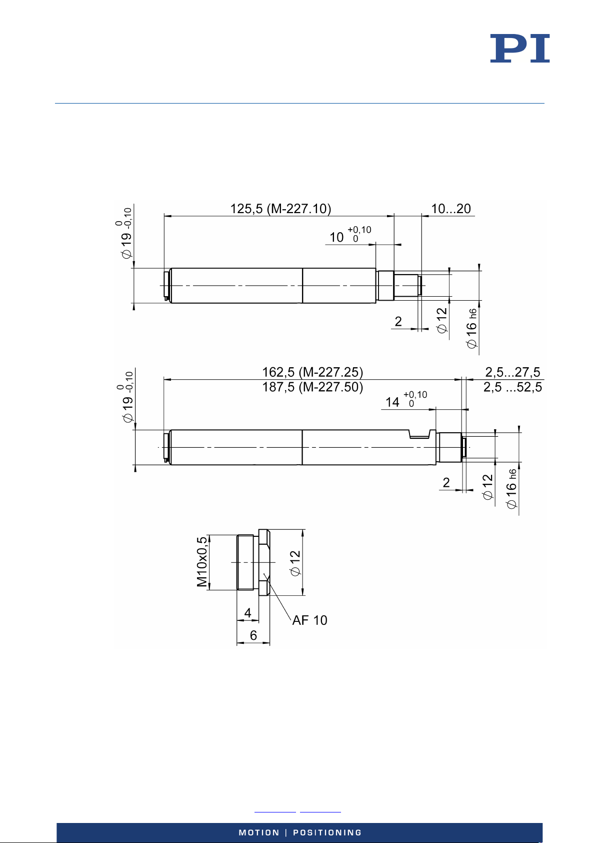
Dimensions in mm. Note that a comma is used in the drawings instead of a decimal point.
Figure 5: Dimensions of the M-227
-0, Fax +49 721 4846-1019, Email [email protected], www.pi.ws
Page 23
User Manual
Physik Instrumente (PI) GmbH & Co. KG, Auf der Roemerstrasse 1, 76228 Karlsruhe, Germany Page 23 / 26
Phone +49 721 4846
MP40E, version 1.2.0, valid for M-227.10, M-227.25, M-227.50
CBo, 5/20/2019
Dimensions of the P-885.20 Piezo Actuator
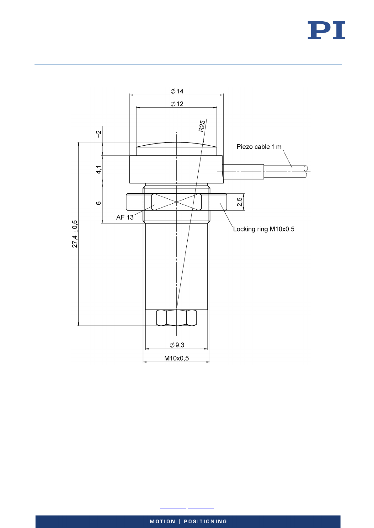
Figure 6: P-885.20 piezo actuator (optional accessory)
-0, Fax +49 721 4846-1019, Email [email protected], www.pi.ws
Page 24
User Manual
Physik Instrumente (PI) GmbH & Co. KG, Auf der Roemerstrasse 1, 76228 Karlsruhe, Germany Page 24 / 26
Phone +49 721 4846
MP40E, version 1.2.0, valid for M-227.10, M-227.25, M-227.50
CBo, 5/20/2019
Dimensions of the M-219 Tips
Figure 7: M-219.xx tips (optional accessories)
-0, Fax +49 721 4846-1019, Email [email protected], www.pi.ws
Page 25
User Manual
Physik Instrumente (PI) GmbH & Co. KG, Auf der Roemerstrasse 1, 76228 Karlsruhe, Germany Page 25 / 26
Phone +49 721 4846
MP40E, version 1.2.0, valid for M-227.10, M-227.25, M-227.50
CBo, 5/20/2019
Pin Assignment
Connector: D-sub 15 (m)
Figure 8: Front view of the D-sub 15 (m) connector (not the solder side)
Pin Function
1 Internal use
2 Motor (+) input
3 Internal use
4 +5 V input
5 Not used
6 GND (logic)
7 A(-) when using RS-422 transmission
8 B(-)when using RS-422 transmission
9 Motor ( - ) input
10 Internal use
11 Internal use
12 Not used
13 Not used
14 Encoder A (A(+) when using RS-422 transmission)
15 Encoder B (B(+) when using RS-422 transmission)
-0, Fax +49 721 4846-1019, Email [email protected], www.pi.ws
Page 26
User Manual
Physik Instrumente (PI) GmbH & Co. KG, Auf der Roemerstrasse 1, 76228 Karlsruhe, Germany Page 26 / 26
Phone +49 721 4846
MP40E, version 1.2.0, valid for M-227.10, M-227.25, M-227.50
CBo, 5/20/2019
Old Equipment Disposal
In accordance with EU law, electrical and electronic equipment may not be disposed of in EU
member states via the municipal residual waste.
Dispose of your old equipment according to international, national, and local rules and
regulations.
In order to fulfil its responsibility as the product manufacturer, Physik Instrumente (PI) GmbH &
Co. KG undertakes environmentally correct disposal of all old PI equipment made available on
the market after 13 August 2005 without charge.
Any old PI equipment can be sent free of charge to the following address:
Physik Instrumente (PI) GmbH & Co. KG
Auf der Roemerstr. 1
D-76228 Karlsruhe, Germany
-0, Fax +49 721 4846-1019, Email [email protected], www.pi.ws
 Loading...