

Page 1
User Manual
PI (Physik Instrumente) L.P.
16 Albert Street, Auburn, MA 01501
Tel: 508-832-3456 Fax: 508-832-0506
Email: [email protected]
A620D0001 Rev 1.2
30-July-2019
A-62x Series Rotary Air Bearing Stage
PIglide RM, Direct-drive Torque Motor Driven with Encoder Feedback
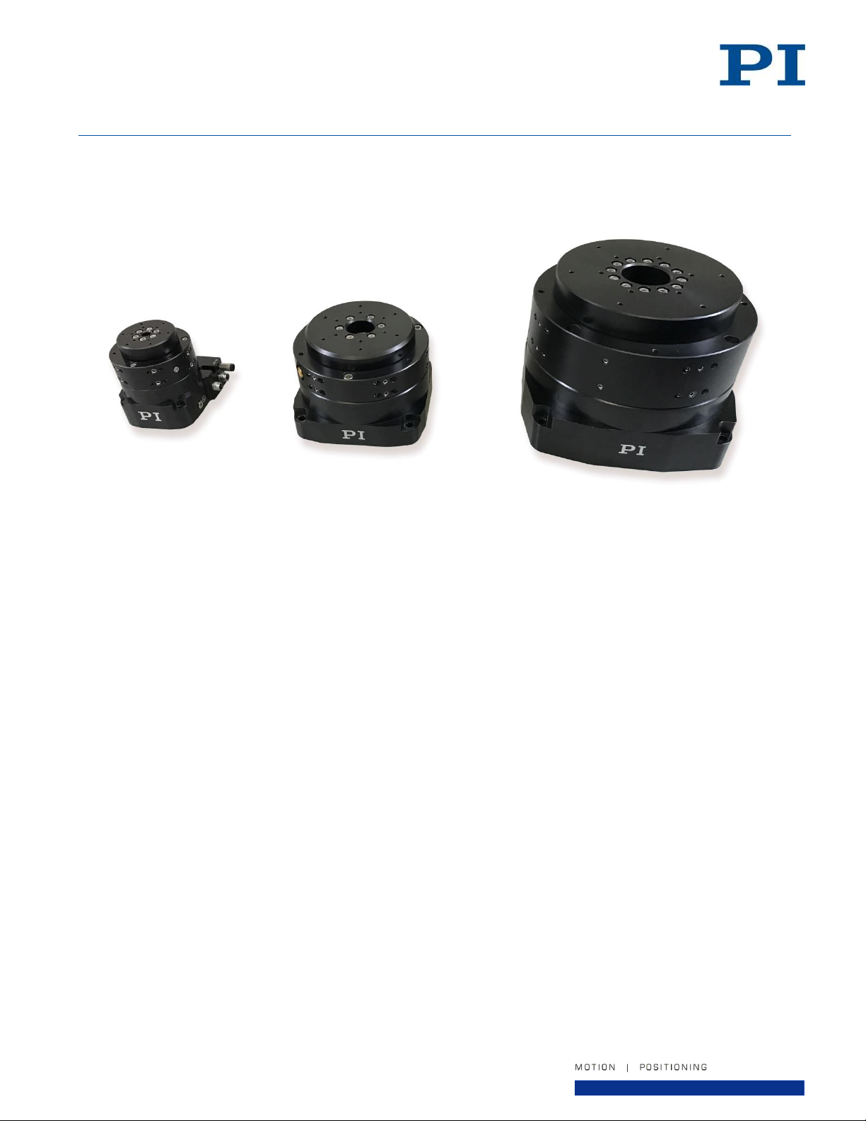
This document describes the A-62x.xxxxx Series of Rotary Air Bearing Motorized Stages.
Page 1 of 32
Page 2

User Manual
PI (Physik Instrumente) L.P.
16 Albert Street, Auburn, MA 01501
Tel: 508-832-3456 Fax: 508-832-0506
Email: [email protected]
A620D0001 Rev 1.2
30-July-2019
Physik Instrumente (PI) GmbH & Co. KG is the owner of the following trademarks:
PI®, PIC®, PICMA®, PILine®, PIFOC®, PiezoWalk®, NEXACT®, NEXLINE®, NanoCube®, NanoAutomation®,
Picoactuator®, PInano®, PIMag®
PI owns the following patents or patent applications for the technology field Magnetic Direct Drives (PIMag®):
WO212146709A2, DE102012207082A1
© 2019 PI (Physik Instrumente) L.P. The text, photographs and drawings in this manual are protected by
copyright. With regard thereto, PI (Physik Instrumente) L.P. retains all the rights. Use of said text, photographs
and drawings is permitted only in part and only upon citation of the source.
Subject to change without notice. This manual is superseded by any new release. PI continually improves its
product offerings, and listed options and specifications may be superseded at any time.
Page 2 of 32
Page 3

User Manual
PI (Physik Instrumente) L.P.
16 Albert Street, Auburn, MA 01501
Tel: 508-832-3456 Fax: 508-832-0506
Email: [email protected]
A620D0001 Rev 1.2
30-July-2019
Table of Contents
1. About this Document ____________________________________________________________________5
1.1. Objective and Target Audience of this User Manual ________________________________________5
1.2. Symbols and Typographic Conventions __________________________________________________5
1.3. Other Applicable Documents __________________________________________________________5
2. Safety ________________________________________________________________________________6
2.1. Intended Use ______________________________________________________________________6
2.2. General Safety Instructions ___________________________________________________________6
2.3. Warnings and Safety Notices __________________________________________________________7
2.4. Organizational Measures _____________________________________________________________8
3. Product Description _____________________________________________________________________9
3.1. Model Overview and Part Numbering ___________________________________________________9
3.2. Product Features _________________________________________________________________ 10
3.3. Product Labeling __________________________________________________________________ 11
3.4. Scope of Delivery _________________________________________________________________ 12
3.5. Accessories ______________________________________________________________________ 12
3.6. Controllers ______________________________________________________________________ 12
4. Technical Features ____________________________________________________________________ 13
4.1. Air Bearing ______________________________________________________________________ 13
4.2. Torque Motor ____________________________________________________________________ 13
4.3. Encoder _________________________________________________________________________ 13
4.4. Index Mark (Incremental encoders only) _______________________________________________ 13
5. Unpacking and Handling ________________________________________________________________ 14
6. Installation __________________________________________________________________________ 15
6.1. Mounting Surface Quality and Preparation _____________________________________________ 15
6.2. Mounting Orientation _____________________________________________________________ 15
6.3. Mounting Procedure ______________________________________________________________ 16
6.4. Removing the shipping restraint _____________________________________________________ 16
6.5. Air Supply _______________________________________________________________________ 17
6.6. Affixing the Payload to the Stage _____________________________________________________ 18
Page 3 of 32
Page 4

User Manual
PI (Physik Instrumente) L.P.
16 Albert Street, Auburn, MA 01501
Tel: 508-832-3456 Fax: 508-832-0506
Email: [email protected]
A620D0001 Rev 1.2
30-July-2019
6.7. Multi-Axis Configurations ___________________________________________________________ 18
6.8. Connecting the Stage to Protective Earth ______________________________________________ 19
6.9. Connecting the Cables _____________________________________________________________ 20
7. Startup and Operation of the Stage _______________________________________________________ 21
8. Maintenance _________________________________________________________________________ 22
8.1. Cleaning the Stage ________________________________________________________________ 22
8.2. Preparing the Stage for Transport ____________________________________________________ 22
9. Customer Service _____________________________________________________________________ 23
10. Technical Data _____________________________________________________________________ 24
10.1. Sizes and Load Capacities _________________________________________________________ 24
10.2. Performance Specifications _______________________________________________________ 24
10.3. Motor Electrical Specifications _____________________________________________________ 25
10.4. Encoder Specifications ___________________________________________________________ 25
10.5. Ambient Conditions _____________________________________________________________ 26
10.6. Dimensions ____________________________________________________________________ 26
10.7. Pin Assignments ________________________________________________________________ 31
11. EC Declaration of Conformity __________________________________________________________ 32
12. Old Equipment Disposal ______________________________________________________________ 32
Table of Figures
Figure 1 - Product Features, A-62x ___________________________________________________________ 10
Figure 2 - Product Labeling Example __________________________________________________________ 11
Figure 3 - Mounting Surface Quality ___________________________________________________________ 15
Figure 4 - Shipping Restraint ________________________________________________________________ 16
Figure 5 - Air Inlet Fitting Location ____________________________________________________________ 17
Figure 6 - Air Exhaust Port Location___________________________________________________________ 17
Figure 7 - Earth ground connection point location ________________________________________________ 19
Figure 8 - Mounting of the protective earth conductor (profile view) __________________________________ 19
Figure 9 - Stage Electrical Cable Connectors ___________________________________________________ 20
Figure 10 - A-621.025x1 Stage Dimensions ____________________________________________________ 26
Figure 11 - A-623.xxxx1 Stage Dimensions _____________________________________________________ 27
Figure 12 - A-624.050x1 Stage Dimensions ____________________________________________________ 28
Figure 13 - A-625.065x1 Stage Dimensions ____________________________________________________ 29
Figure 14 - A-627.075x1 Stage Dimensions ____________________________________________________ 30
Page 4 of 32
Page 5
User Manual
PI (Physik Instrumente) L.P.
16 Albert Street, Auburn, MA 01501
Tel: 508-832-3456 Fax: 508-832-0506
Email: [email protected]
Symbol
Meaning
If not avoided, the situation could result in damage to the equipment.
Failure to observe these precautions could result in serious injury to
those performing the procedures and damage to the equipment.
1.
2.
Action consisting of several steps whose sequential order must be
observed
Action consisting of one or several steps whose sequential order is
irrelevant
A620D0001 Rev 1.2
30-July-2019
1. About this Document
1.1. Objective and Target Audience of this User Manual
This manual contains information on the intended use of the A-62x series of linear motor-driven air bearing
stages. It assumes that the reader has a fundamental understanding of basic servo systems as well as motion
control concepts and applicable safety procedures.
1.2. Symbols and Typographic Conventions
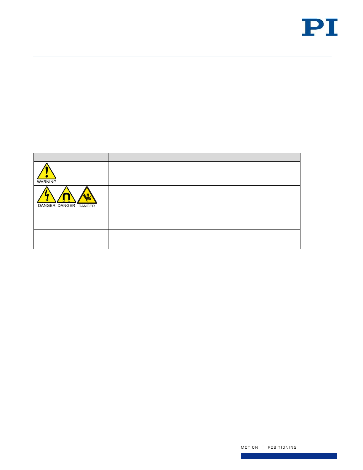
The following symbols and markings are used in this User Manual:
1.3. Other Applicable Documents
None at this time
Page 5 of 32
Page 6

User Manual
PI (Physik Instrumente) L.P.
16 Albert Street, Auburn, MA 01501
Tel: 508-832-3456 Fax: 508-832-0506
Email: [email protected]
A620D0001 Rev 1.2
30-July-2019
2. Safety
2.1. Intended Use
The A-62x is a laboratory device as defined by DIN EN 61010. It is intended to be used in interior spaces and in
an environment which is free of dirt, oil and lubricants.
In accordance with its design and realization, the A-62x is intended for single-axis positioning of loads at different
velocities. The A-62x is not intended for applications in areas in which a failure would present severe risks to
human beings or the environment.
The intended use of the A-62x is only possible when completely mounted and connected.
The A-62x must be operated with a suitable controller. The controller is not included in the scope of delivery of
the A-62x.
2.2. General Safety Instructions
The A-62x is built according to state-of-the-art technology and recognized safety standards. Improper use can
result in personal injury and/or damage to the A-62x.
Only use the A-62x for its intended purpose, and only use it if it is in a good working order.
Read the user manual.
Immediately eliminate any faults and malfunctions that are likely to affect safety.
The operator is responsible for the correct installation and operation of the A-62x.
Page 6 of 32
Page 7
User Manual
PI (Physik Instrumente) L.P.
16 Albert Street, Auburn, MA 01501
Tel: 508-832-3456 Fax: 508-832-0506
Email: [email protected]
To minimize the possibility of electrical shock and bodily injury or death, disconnect all electrical
power prior to making any electrical connections.
To minimize the possibility of electrical shock and bodily injury or death when any electrical circuit
is in use, ensure that no person comes in contact with the circuitry when the stage is connected to
a power source.
To minimize the possibility of bodily injury or death, disconnect all electrical power prior to making
any mechanical adjustments.
To minimize the possibility of bodily injury or death from electric shock in the case of malfunction
or failure of the system, make sure a protective earth conductor is properly connected.
Moving parts of the stage can cause crushing or shearing injuries. All personnel must remain clear
of any moving parts.
The stage table should never be moved without the air supply turned on. Moving the stage table
with no air supply, causing sliding metal-to-metal contact, may damage the bearing surfaces.
Improper use of the stage can cause damage, shock, injury, or death. Read and understand this
manual before operating the stage.
If the stage is used in a manner not specified by the manufacturer, the protection provided by the
stage can be impaired.
Stage cables can pose a tripping hazard. Securely mount and position all stage cables to avoid
potential hazards.
Do not expose the stage to environments or conditions outside the specified range of operating
environments. Operation in conditions other than those specified can cause damage to the
equipment.
The stage must be mounted securely. Improper mounting can result in injury and damage to the
equipment.
Use care when moving the stage. Manually lifting or transporting stages can result in injury.
Use care when moving the stage. Avoid any shocks, drops or bumps that can cause scratches,
dings, dents, or distortion of the stage.
A620D0001 Rev 1.2
30-July-2019
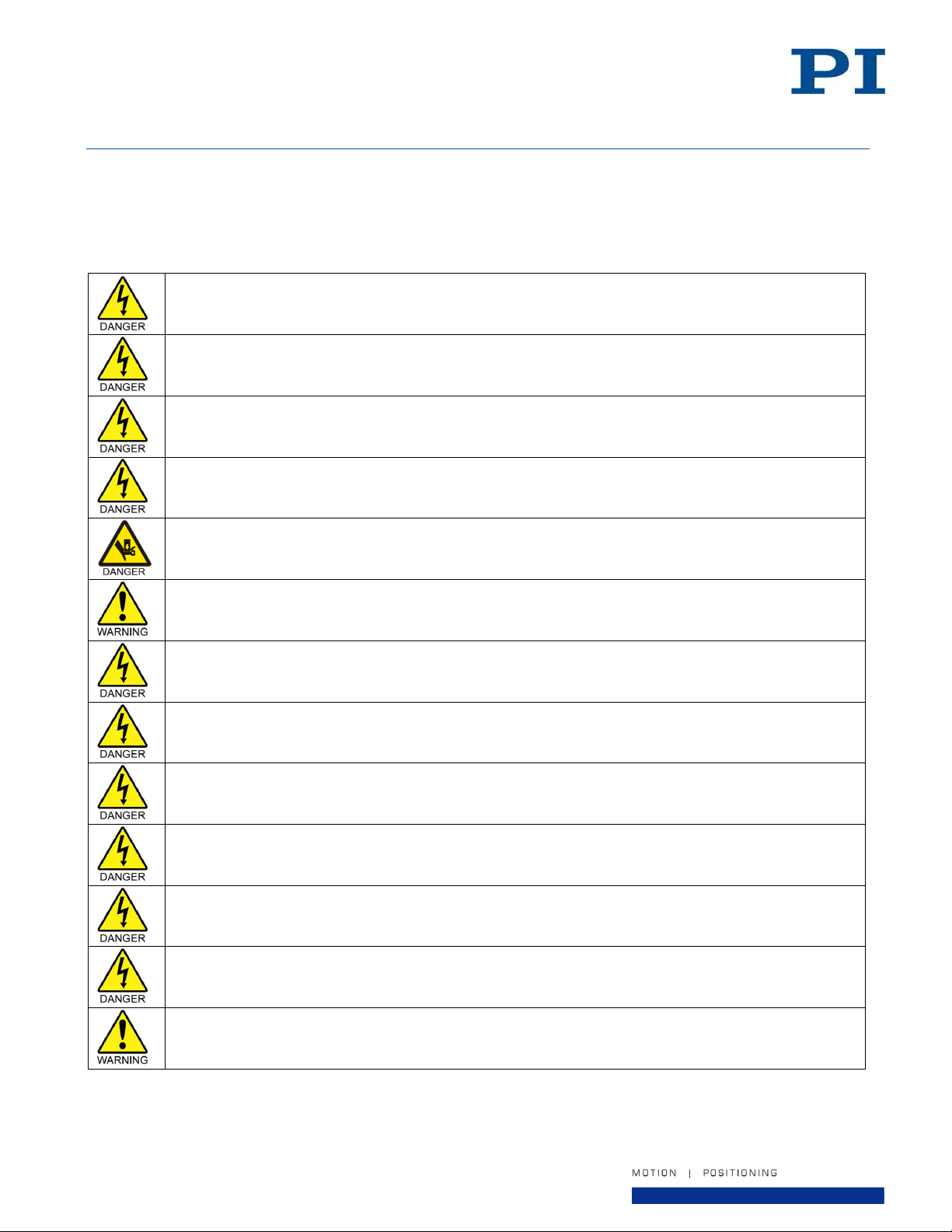
2.3. Warnings and Safety Notices
The following statements apply throughout this manual. Failure to observe these precautions could result in
serious injury to those performing the procedures and damage to the equipment. This manual and any additional
instructions included with the stage should be retained for the lifetime of the stage.
Page 7 of 32
Page 8
User Manual
PI (Physik Instrumente) L.P.
16 Albert Street, Auburn, MA 01501
Tel: 508-832-3456 Fax: 508-832-0506
Email: [email protected]
The stage contains high power magnets that can attract ferrous objects, such as loose screws.
Attracted objects can damage the stage. Make sure that there are no movable, ferrous objects
within a radius of at least 10 cm around the stage.
The stage contains high power magnets that can damage magnetically sensitive objects such as
magnetic data carriers and electronic devices. Make sure that there are no magnetically sensitive
objects within a radius of at least 10 cm around the stage.
Dirt, oil, lubricants and condensation will damage the stage. Keep the stage clean and free of dirt,
debris, oil, lubricants, and moisture.
A620D0001 Rev 1.2
30-July-2019
2.4. Organizational Measures
User manual
Always keep this user manual available near the A-62x.
Add all information given by the manufacturer to the user manual, for example supplements or
Technical Notes.
If you pass the A-62x on to other users, also turn over this user manual as well as other relevant
information provided by the manufacturer.
Only use the device on the basis of the complete user manual. Missing information due to an
incomplete user manual can result in minor injury and property damage.
Only install and operate the A-62x after having read and understood this user manual.
Personnel qualification
The A-62x may only be installed, started up, operated, maintained and cleaned by authorized and
appropriately qualified personnel.
Page 8 of 32
Page 9
User Manual
PI (Physik Instrumente) L.P.
16 Albert Street, Auburn, MA 01501
Tel: 508-832-3456 Fax: 508-832-0506
Email: [email protected]
Model
Table Diameter
Journal Length
Encoder Option
Motor
A-62
1 = 50mm
025 = 25mm
A = Incremental, Sine (1 Vp-p) output
1 = Standard motor
option, slotless
3 = 100mm
025 = 25mm
B = Absolute BiSS-C serial output
050 = 50mm
4 = 150 mm
050 = 50mm
5 = 200mm
065 = 65mm
7 = 300mm
075 = 75mm
A620D0001 Rev 1.2
30-July-2019
3. Product Description
3.1. Model Overview and Part Numbering
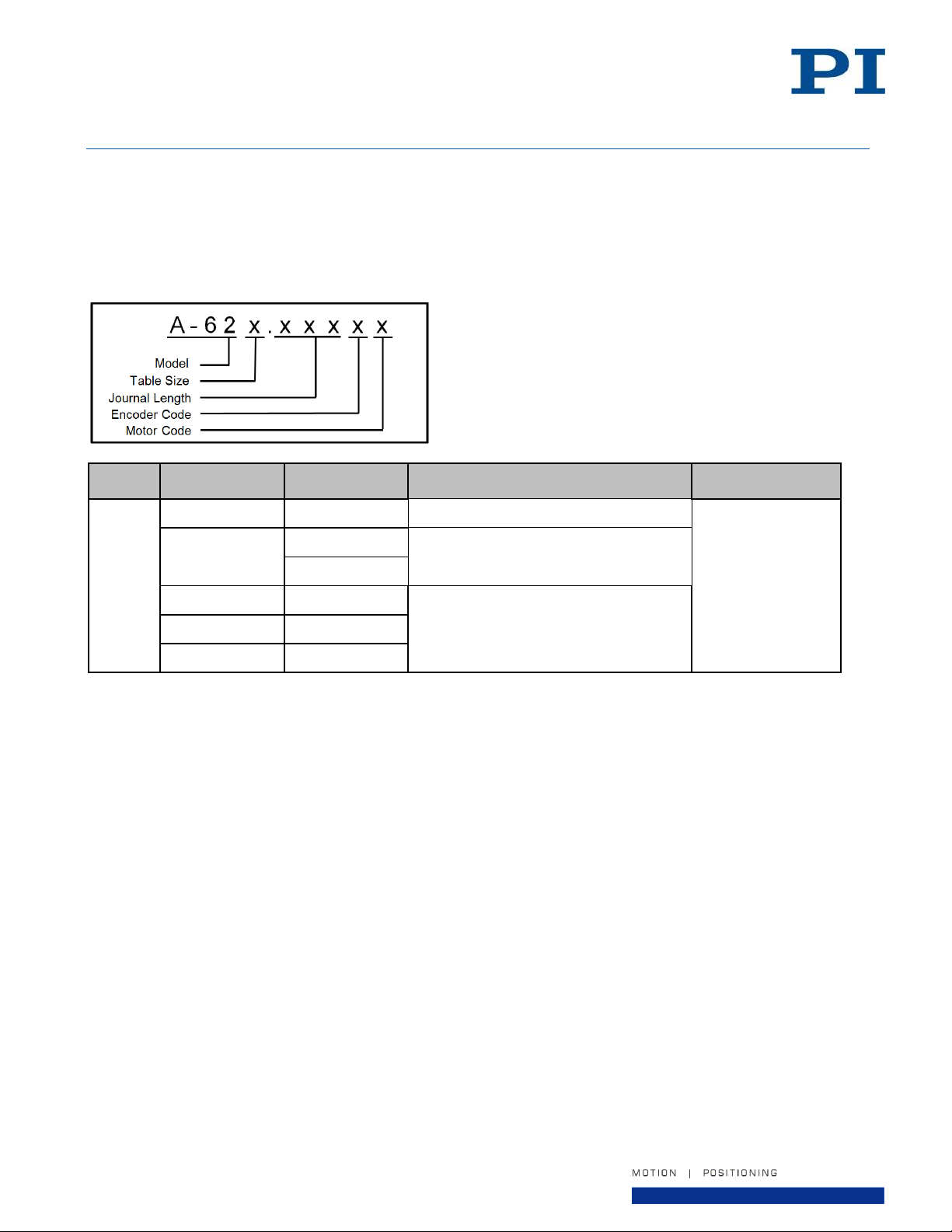
The A-62x series offers various models, defined by the stage size, encoder type, and motor option. The
dimensions of the various models vary. Encoder and motor options do not affect the dimensions.
Page 9 of 32
Page 10

User Manual
PI (Physik Instrumente) L.P.
16 Albert Street, Auburn, MA 01501
Tel: 508-832-3456 Fax: 508-832-0506
Email: [email protected]
#
Description
1.
Stage base
2.
Moving table
3.
Motor electrical connection
4.
Encoder electrical connection
5.
Air supply inlet
6.
Air exhaust port
A620D0001 Rev 1.2
30-July-2019
3.2. Product Features
The A-62x series stages all incorporate completely non-contact fully preloaded air bearings, direct-drive torque
motors, and optical position feedback encoders to provide a maintenance free stage. There is no mechanical
contact to wear or require lubrication, making these stages ideal for clean room and medical applications. The
brushless torque motor uses an ironless slotless motor coil, which means there is zero cogging and no attractive
forces – resulting in unsurpassed smoothness of motion. This is especially useful in applications where velocity
control is important.
The air bearing, motor, and encoder are housed in the internals of the stage and are not visible to the user.
Figure 1 - Product Features, A-62x
Page 10 of 32
Page 11
User Manual
PI (Physik Instrumente) L.P.
16 Albert Street, Auburn, MA 01501
Tel: 508-832-3456 Fax: 508-832-0506
Email: [email protected]
#
Description
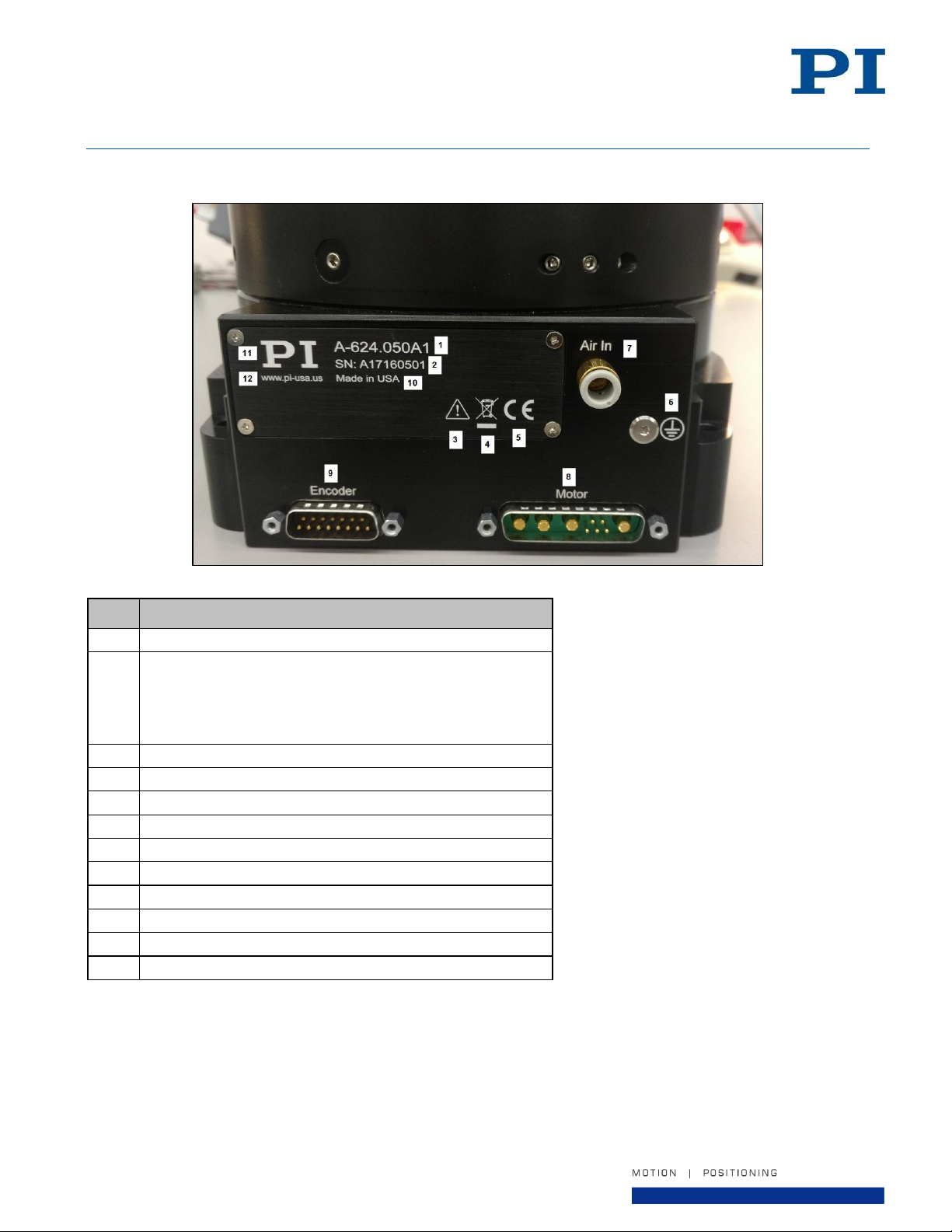
1.
Product model number (example)
2.
Serial number (example), individual for each A-62x
Meaning of the places (counting from left):
A = PIglide Air Bearing Product
17 = year of manufacture (i.e. 2017)
160501 = unique number, 6-digit
3.
Warning sign "Observe manual"
4.
Old equipment disposal warning sign
5.
CE conformity mark
6.
Protective earth grounding location
7.
Air supply inlet location
8.
Motor electrical connection
9.
Encoder electrical connection
10.
Country of origin
11.
Manufacturer's address (website)
12.
Manufacturer's logo
A620D0001 Rev 1.2
30-July-2019
3.3. Product Labeling
Figure 2 - Product Labeling Example
Page 11 of 32
Page 12

User Manual
PI (Physik Instrumente) L.P.
16 Albert Street, Auburn, MA 01501
Tel: 508-832-3456 Fax: 508-832-0506
Email: [email protected]
Item ID
Component
A-62x.xxxxxx
Stage according to the order
---
Stage Mounting Screws (size will depend on the stage
model ordered)
---
Shipping restraint
A620D0001
User manual (this document)
Part #
Description
A-80x.xxx
Air Preparation and Filtration Kit
A-851.xxx
Cable sets for integration with various controllers
Part #
Description
C-891.120200
PIMag® Motion Controller for magnetic direct drives,
1 channel, 24 V, 3 A, USB and RS-232 interfaces
A-81x.xxxxx
A-82x.xxxxx
PIglide Family of Motion Controllers (1, 2, 4, 6, or 8 Axes)
A620D0001 Rev 1.2
30-July-2019
3.4. Scope of Delivery
3.5. Accessories
The following accessories are offered to complement the A-62x stage. Contact PI for all available configurations.
3.6. Controllers
The A-62x must be connected to a suitable motion controller to be operated. The following standard controllers
are available from PI to operate the A-62x. Other controllers are also available, contact PI for options.
Page 12 of 32
Page 13

User Manual
PI (Physik Instrumente) L.P.
16 Albert Street, Auburn, MA 01501
Tel: 508-832-3456 Fax: 508-832-0506
Email: [email protected]
A620D0001 Rev 1.2
30-July-2019
4. Technical Features
4.1. Air Bearing
The A-62x series stage features fully preloaded, non-contact, frictionless air bearings to guide the motion of the
stage and support the payload. This air bearing is a highly accurate precision instrument. The non-contact
nature of the air bearings will provide years of accurate and reliable use if treated properly. Keep the bearing
clean and avoid any shocks, drops or bumps that can cause scratches, dings or distortion of the bearing.
The A-62x incorporates opposing axial and radial preload mechanisms. This sort of preload makes the A-62x
suitable for various mounting orientations, such as horizontal, vertical, and inverted. Be careful not to apply
excess cantilever loads to the stage table.
4.2. Torque Motor
The A-62x series stage features a brushless, ironless, slotless 3-phase torque motor. This type of motor
technology is completely non-contact and is ideally suited to high speeds; high accelerations; fine resolution
positioning; and smooth, constant-velocity scanning. The motor must be commutated by an external motor drive.
Hall Effect sensors are not included, so the drive and/or controller must be capable of encoder-based (sine)
commutation.
4.3. Encoder
The A-62x series stage features an optical non-contact position encoder for direct measurement of the stage
position. This feedback signal is used by an external motion controller to close the servo loop for position and
velocity control.
The A-62x series stage offers two types of encoders:
Incremental with analog (sine) output: Suitable for use with controllers using on-board encoder interpolation.
Absolute with BiSS-C 32-bit serial output: Eliminates the need for startup homing routines and limit switches.
4.4. Index Mark (Incremental encoders only)
When equipped with either of the incremental encoder options, the A-62x series stage features a non-contact
home index marker. The index is integral to the encoder electronics. The index mark is optical; there is one
index per revolution of the stage.
Page 13 of 32
Page 14
User Manual
PI (Physik Instrumente) L.P.
16 Albert Street, Auburn, MA 01501
Tel: 508-832-3456 Fax: 508-832-0506
Email: [email protected]
The A-62x stage must always be transported and shipped with the shipping restraint installed.
Failure to use the shipping restraint when moving, transporting, or shipping the stage may allow
movement between the stage table and stage base, causing damage.
The stage table should never be moved without the air supply turned on. Moving the stage table
with no air supply, causing sliding metal-to-metal contact, may damage the bearing surfaces.
Use care when moving the stage. Manually lifting or transporting stages can result in injury.
Use care when moving the stage. Avoid any shocks, drops or bumps that can cause scratches,
dings, dents, or distortion of the stage.
When lifting the A-62x, take care to lift only by the base plate of the stage. Do not lift using any
other part of the mechanical system, or damage may occur.
The A-62x stage weighs up to 50 kg in its largest size. Use care when lifting and use two people to
lift.
A620D0001 Rev 1.2
30-July-2019
5. Unpacking and Handling
Carefully unpack the air bearing stage and other components from the shipping packaging. Inspect the contents
for signs of damage. If there is any sign of damage or missing parts, contact PI immediately. Compare the
package contents to packing list and notify PI immediately if any parts are missing or incorrect. Keep all
packaging materials in case the product needs to be returned.
Before mounting or using the stage, it is recommended to let the stage stabilize at room temperature for at least
24 hours. Clean any dust or shipping debris off the stage by blowing it off with pressurized nitrogen or clean, oilfree air.
If the stage will be mounted in such a way as to block the product label, it is recommended to record the stage
serial number for future reference.
Page 14 of 32
Page 15
User Manual
PI (Physik Instrumente) L.P.
16 Albert Street, Auburn, MA 01501
Tel: 508-832-3456 Fax: 508-832-0506
Email: [email protected]
A620D0001 Rev 1.2
30-July-2019
6. Installation
6.1. Mounting Surface Quality and Preparation
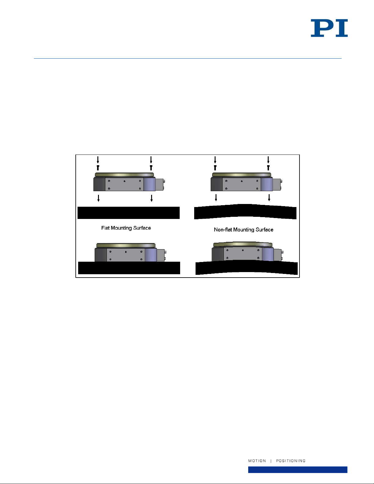
The surface to which the stage will be mounted should be flat and have adequate stiffness in order to achieve the
maximum performance from the A-62x. When the A-62x series stage is mounted to a non-flat surface, the stage
can be distorted as the mounting screws are tightened. This distortion will decrease the overall accuracy of the
stage. The effects of flatness on mounting are illustrated below.
To maintain accuracy, the mounting surface should be flat within 1 µm per 150 mm. A laboratory grade AA
granite surface plate is recommended. Do not shim under the stage base.
Prepare the mounting surface and bottom of the stage base with precision flat stones to remove any burrs or high
spots. Clean the mounting surface and bottom of the stage with the appropriate cleaners (isopropyl alcohol).
6.2. Mounting Orientation
The A-62x is suitable for various mounting orientations, such as horizontal, vertical, and inverted. PI
recommends that you review your payload and orientation conditions with a PI engineer before purchasing this
product.
Figure 3 - Mounting Surface Quality
Page 15 of 32
Page 16
User Manual
PI (Physik Instrumente) L.P.
16 Albert Street, Auburn, MA 01501
Tel: 508-832-3456 Fax: 508-832-0506
Email: [email protected]
Model
Mounting Screw (4x)
Max. Screw Torque (N-m)
A-621.xxxxx
M3 SHCS, 30mm long (minimum)
2
A-623.xxxxx
M6 SHCS, 30mm long (minimum)
20
A-624.xxxxx
M6 SHCS, 40mm long (minimum)
20
A-625.xxxxx
M6 SHCS, 30mm long (minimum)
20
A-627.xxxxx
M8 SHCS, 40mm long (minimum)
48
The shipping restraint kit for the A-62x consists of:
#
Description
1.
Shipping bracket for A-62x
2.
Flat washer
3.
SHCS
4.
Shipping restraint label
Screw sizes used in shipping restraint kits:
Model
Screw Size and Length
A-621
M3 SHCS, 5mm long
A-623
M5 SHCS, 8mm long
A-624
M6 SHCS, 8mm long
A-625
M6 SHCS, 16mm long
A-627
M8 SHCS, 10mm long
A620D0001 Rev 1.2
30-July-2019
6.3. Mounting Procedure
1. Place the stage on the mounting surface.
2. Remove the shipping restraint.
3. Connect the compressed air supply and turn on the air.
4. Affix the stage base to the mounting surface using the four mounting screws provided. Screw size and length
will depend on the stage model, see the table below.
5. Torque the mounting screws (begin from the center out for best accuracy). The typical maximum torque
value for the mounting screws is shown in the table below.
The stage should now be securely mounted. Make sure to allow sufficient clearance to attach the motor and
encoder cables to the stage.
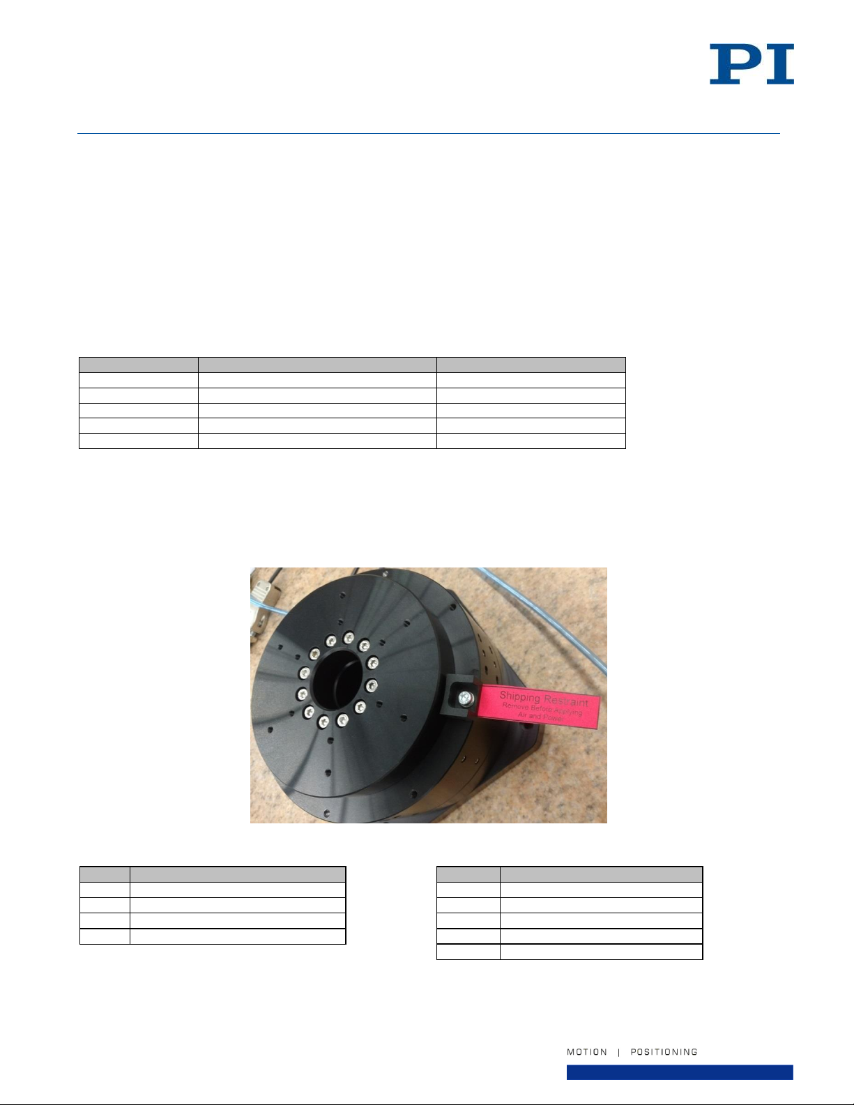
6.4. Removing the shipping restraint
The stage is shipped with a shipping restraint installed to prevent unwanted motion between the stage table and
the stage base. To remove the shipping restraint, unscrew the SHCS using an Allen key. Make sure to safely
store the parts for later use, in case the stage ever needs to be moved or transported.
Figure 4 - Shipping Restraint
Page 16 of 32
Page 17
User Manual
PI (Physik Instrumente) L.P.
16 Albert Street, Auburn, MA 01501
Tel: 508-832-3456 Fax: 508-832-0506
Email: [email protected]
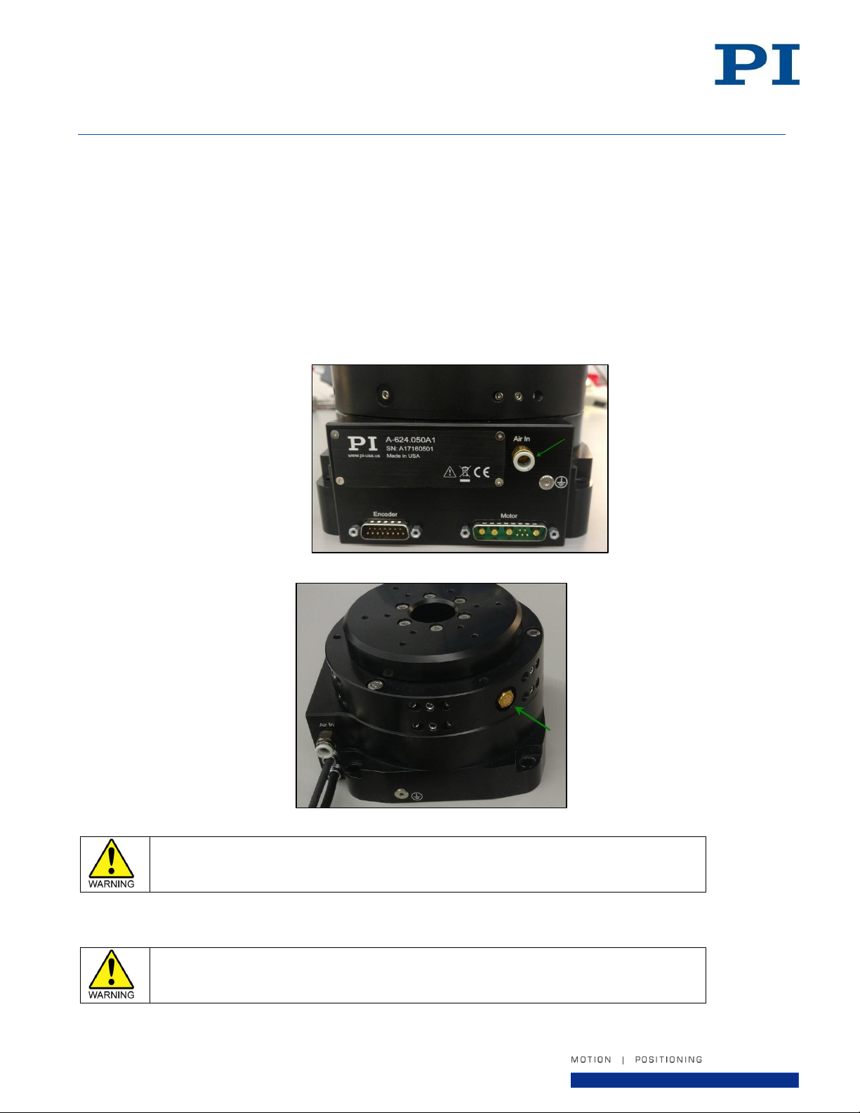
As air flows through the stage, it must eventually exhaust to atmosphere. There is an
exhaust port located on the side of the stage. Do NOT allow this exhaust port to
become blocked or covered.
The stage table should never be moved without the air supply turned on. Moving the
stage table with no air supply, causing sliding metal-to-metal contact, may damage the
bearing surfaces.
A620D0001 Rev 1.2
30-July-2019
6.5. Air Supply
Air Requirements
The A-62x stage requires clean, oil-free, and dry compressed air to operate properly. See Section 10.2 for
detailed air supply requirements.
It is recommended that a pressure switch is installed to monitor air supply pressure and to remove power from
the stage motor if supply pressure drops below 40 psi to prevent damage to the air bearing surfaces.
The air inlet fitting to the A-62x stage accepts flexible polyurethane pneumatic tubing:
4mm OD for the model A-621 & A-623
6mm OD for the models A-624, A-625 & A-627.
Figure 5 - Air Inlet Fitting Location
Figure 6 - Air Exhaust Port Location
Turning off the air supply when not in use
When the stage is not in use, the air supply may be turned off to preserve compressed air and energy.
Page 17 of 32
Page 18
User Manual
PI (Physik Instrumente) L.P.
16 Albert Street, Auburn, MA 01501
Tel: 508-832-3456 Fax: 508-832-0506
Email: [email protected]
Do not attempt to modify the stage table in any way. Customer modifications may damage the
stage.
The screws used to attach the payload to the stage table should not thread into the stage
tabletop any more than the depth shown on the CAD drawing. Longer screws may damage the
table.
Do not overtighten the payload mounting screws.
Do not exceed the maximum payload specified for the A-62x stage.
A620D0001 Rev 1.2
30-July-2019
6.6. Affixing the Payload to the Stage
The payload should be flat, rigid, and comparable to the stage in quality. For valid system performance, the
mounting interface surface should be flat within 1 µm per 50 mm.
The stage tabletop features tapped holes for mounting the user’s payload. These are the only features that
should be used to attach a payload to the stage. Mounting-hole sizes and patterns will depend on the stage
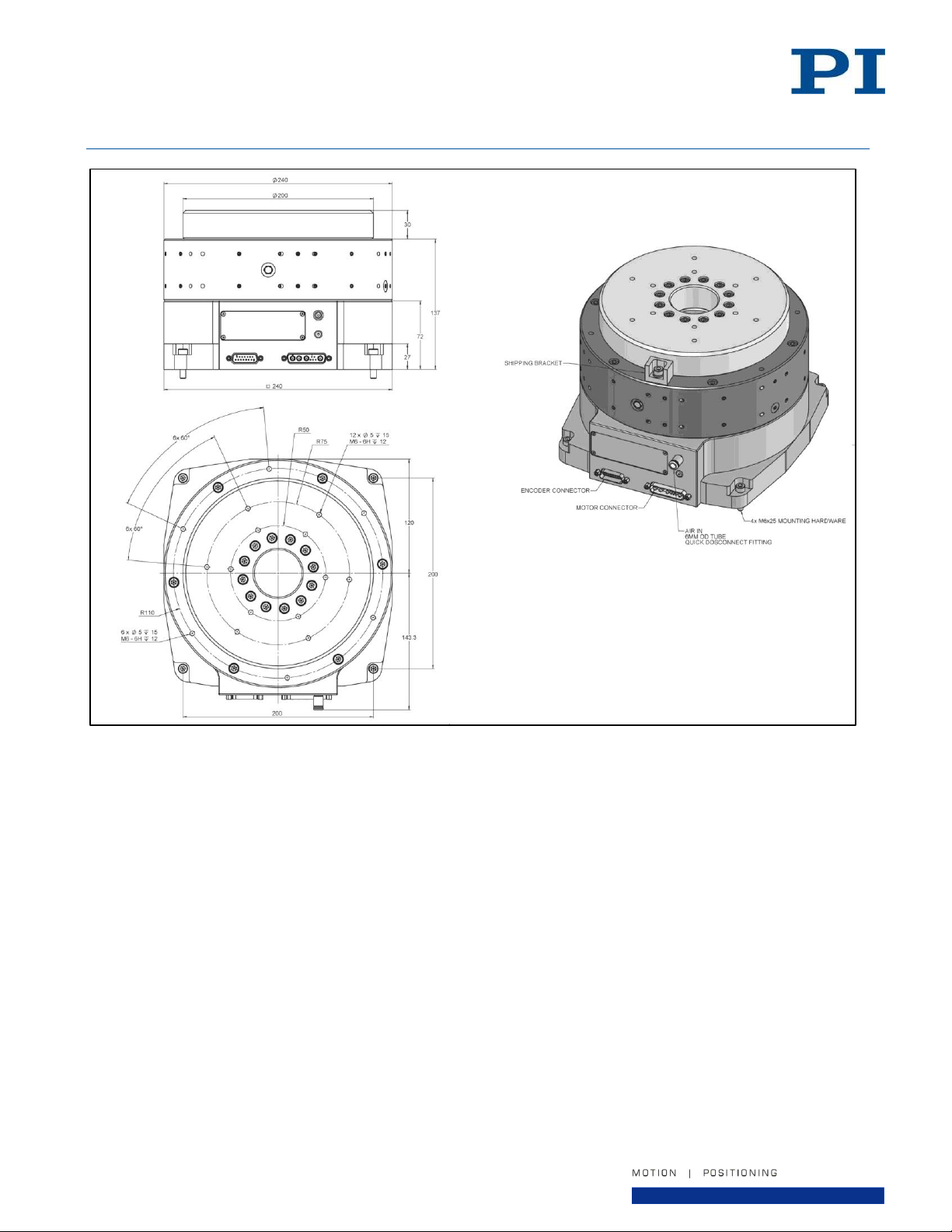
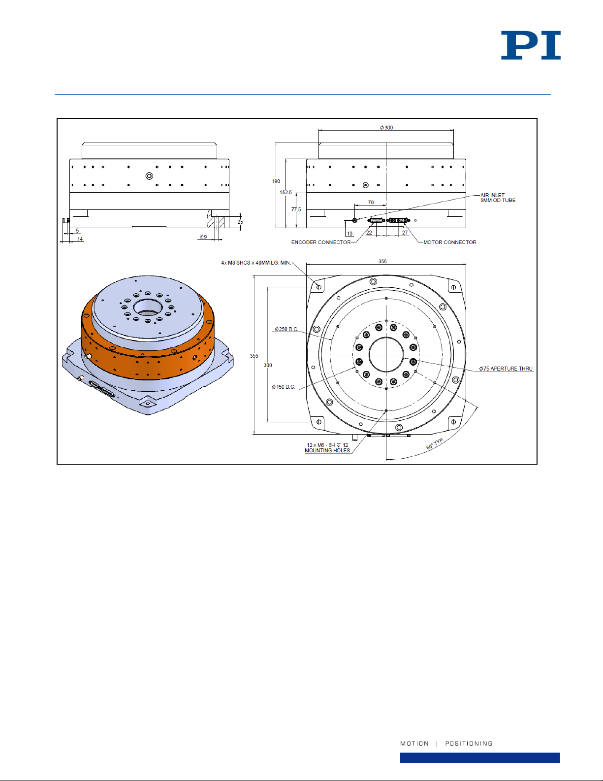
model ordered; see the CAD drawings in Section 10.6 for details.
Prepare the payload mounting surface and the stage table with precision flat stones to remove any burrs or high
spots. Clean the payload mounting surface and the stage table with the appropriate cleaners (isopropyl alcohol).
For optimum performance, the payload center of mass should be centered on the stage tabletop. If the payload
is not centered, the rotating mass will not be balanced about the axis of rotation. Imbalance, especially at higher
rotational speeds, can cause vibration, excessive error motion, and possibly damage to the stage.
6.7. Multi-Axis Configurations
Multi-axis configurations of the A-62x series stage are not available at this time without customization. Please
contact PI for a quote if you require a multi-axis system.
Page 18 of 32
Page 19
User Manual
PI (Physik Instrumente) L.P.
16 Albert Street, Auburn, MA 01501
Tel: 508-832-3456 Fax: 508-832-0506
Email: [email protected]
To minimize the possibility of bodily injury or death from electric shock in the case of malfunction or
failure of the system, make sure a protective earth conductor is properly connected.
#
Description
1.
Base plate of the A-62x
2.
Flat washer (2x)
3.
Internal tooth washer (2x)
4.
M4 Screw
5.
Cable lug
6.
Protective earth conductor
A620D0001 Rev 1.2
30-July-2019
6.8. Connecting the Stage to Protective Earth
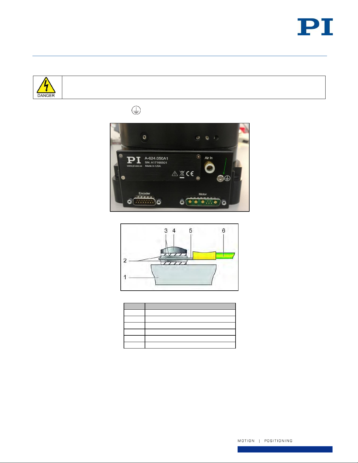
The A-62x has an M4 threaded hole for connecting the protective earth conductor. This hole is marked with the
symbol for the protective earth ground . The hole is located on the end plate of the stage near the air inlet.
Figure 7 - Earth ground connection point location
Figure 8 - Mounting of the protective earth conductor (profile view)
1. If necessary, fasten a suitable cable lug to the protective earth conductor. Note that the conductor and lug
are not in the scope of delivery of the stage.
2. Fasten the cable lug of the protective earth conductor to the protective earth connection of the A-62x as
shown in the profile view using the M4 screw proved. You will need a 2mm Allen key.
3. Tighten the M4 screw with a torque of 1.2 Nm to 1.5 Nm.
4. Make sure that the contact resistance at all connection points relevant for mounting the protective earth
conductor is <0.1 Ω at 25 A.
Page 19 of 32
Page 20
User Manual
PI (Physik Instrumente) L.P.
16 Albert Street, Auburn, MA 01501
Tel: 508-832-3456 Fax: 508-832-0506
Email: [email protected]
Only use the interconnect cables that have been designed for the combination of stage and
controller being used. Connection using the wrong cable may result in damage to the stage and
the controller.
To minimize the possibility of electrical shock and bodily injury or death, disconnect all electrical
power prior to making any electrical connections.
To minimize the possibility of electrical shock and bodily injury or death when any electrical
circuit is in use, ensure that no person comes in contact with the circuitry when the stage is
connected to a power source.
To minimize the possibility of bodily injury or death, disconnect all electrical power prior to
making any mechanical adjustments.
A620D0001 Rev 1.2
30-July-2019
6.9. Connecting the Cables
Stage interconnect cables are not in the scope of delivery of the A-62x series stage. However, PI offers several
standard cable sets that can be used, depending on the motion controller being used. Contact PI for a quote.
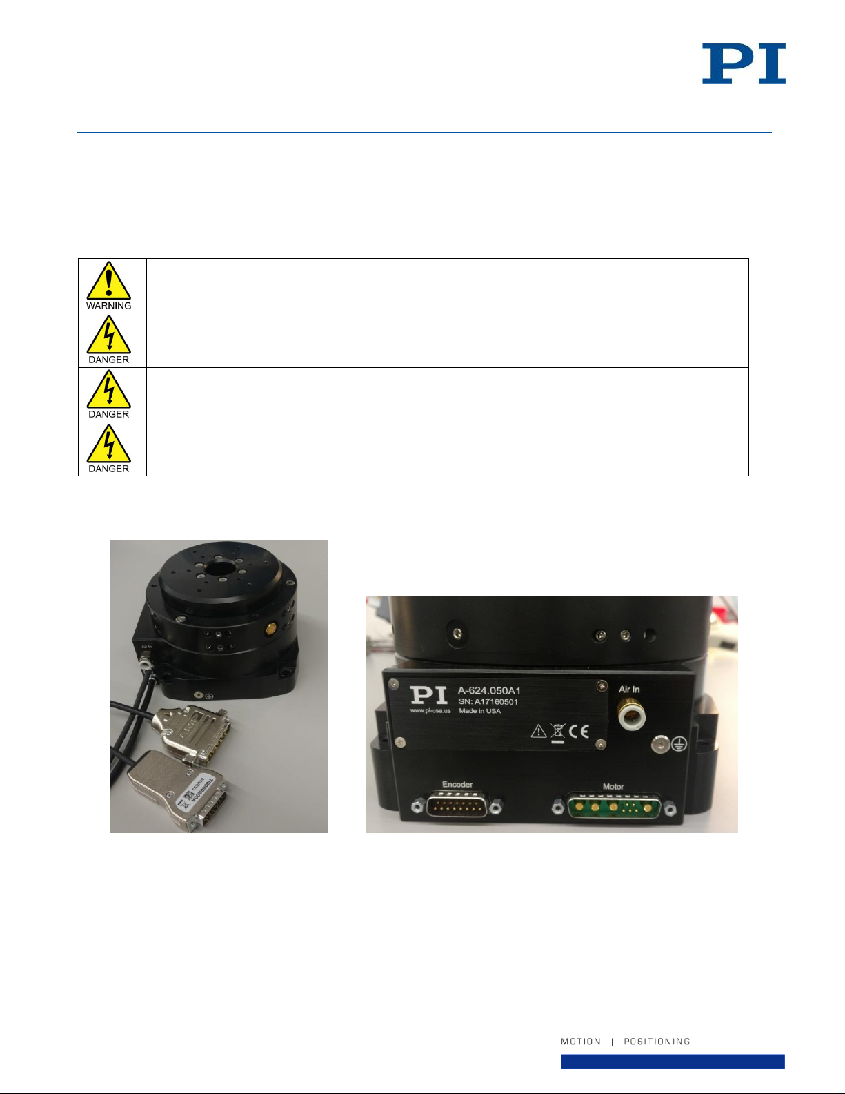
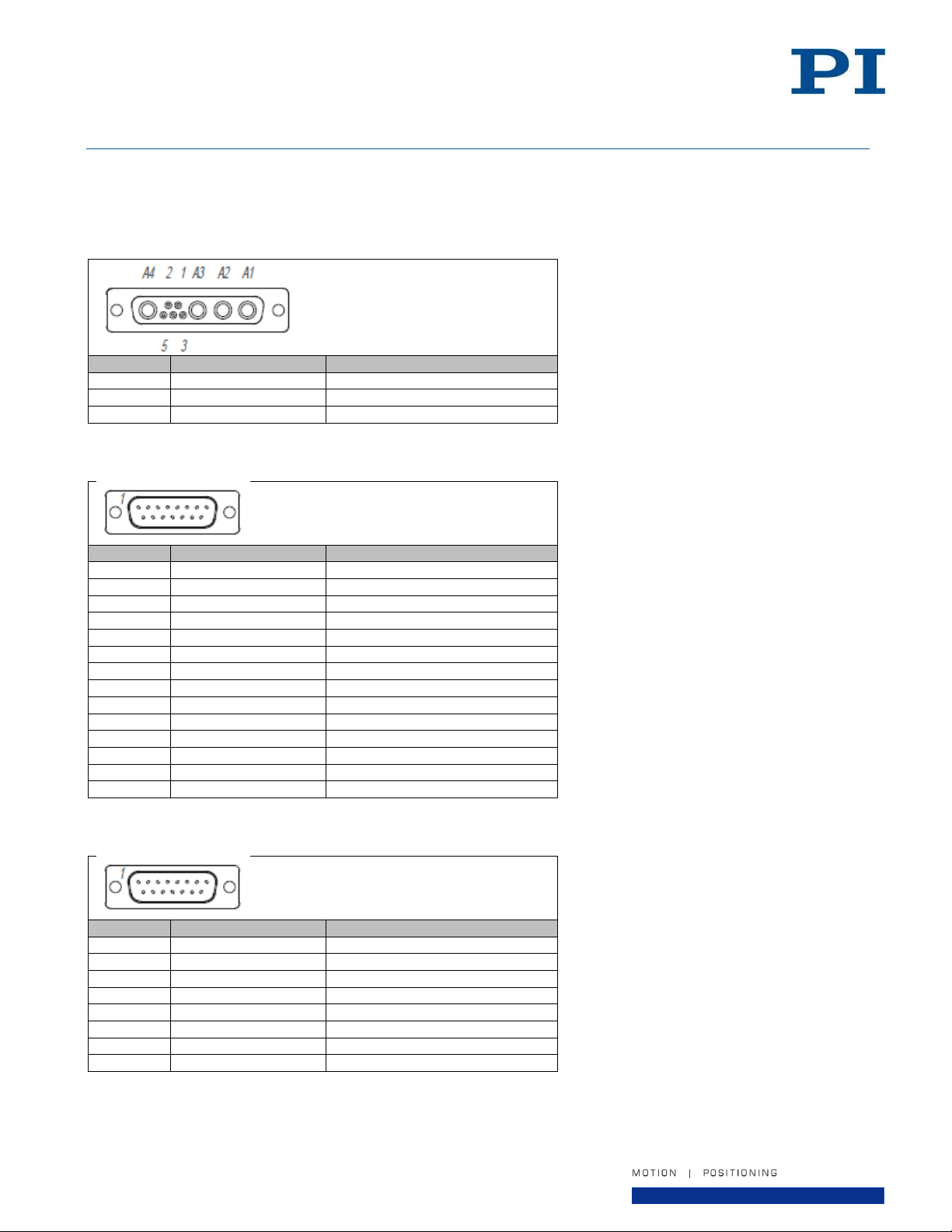
See Section 10.7 for connector pin assignments.
1. Connect the stage cables for the motor and encoder to the connectors on the end plate of the A-62x stage.
2. Tighten the jack screws with a flat head screwdriver to secure the cables. Do not overtighten the screws.
Figure 9 - Stage Electrical Cable Connectors
On the models A-621 and A-623, the electrical connectors are external to the stage body, as shown on the left
photo above. Care should be taken to properly secure the connectors after installation so they do not move and
damage the cables or stage body.
Page 20 of 32
Page 21
User Manual
PI (Physik Instrumente) L.P.
16 Albert Street, Auburn, MA 01501
Tel: 508-832-3456 Fax: 508-832-0506
Email: [email protected]
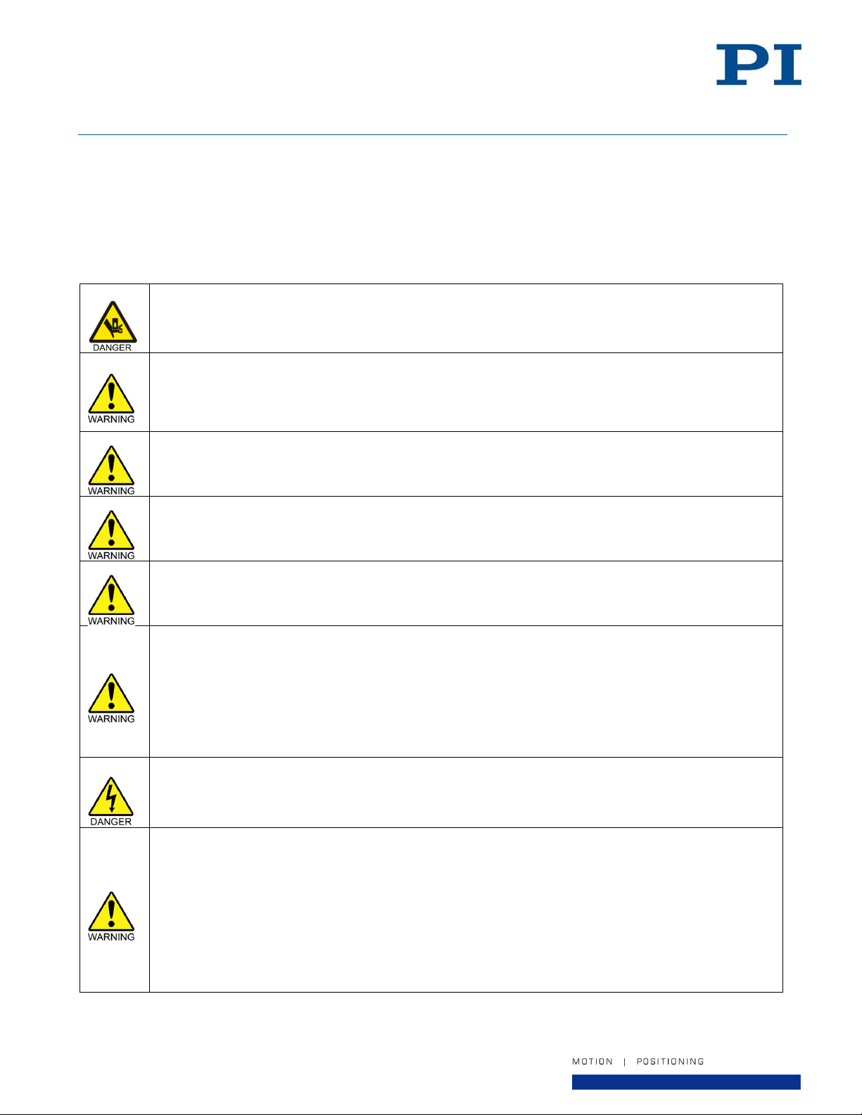
Moving parts of the stage can cause crushing or shearing injuries. All personnel must remain clear
of any moving parts.
Collisions can damage the stage and the payload.
Take care when operating the stage to ensure that no collisions are possible between the
stage, the load to be moved, and the environment in the motion range of the stage.
Do not place any objects in areas where they can be caught by moving parts.
Stop the motion immediately if a controller malfunction occurs.
Do not attempt to operate the stage with the shipping restraint installed.
The A-62x can develop high forces and accelerations. If the stage has been improperly or
incompletely installed, the stage, the payload, and the environment can be damaged during
operation.
The stage table should never be moved without the air supply turned on. Moving the stage table
with no air supply, causing sliding metal-to-metal contact, may damage the bearing surfaces.
The drive mechanism of the A-62x is not self-locking. The stage can therefore unintentionally move
in the following cases:
Switching off or restarting the controller
Switching off the servo mode for the axis
Unintentional displacement can damage the stage, the payload to be moved, and the environment.
Only operate the A-62x with a horizontally aligned motion axis.
Before switching off or rebooting the controller, take suitable measures to ensure that no
unintentional displacement of the stage table is possible.
Do not exceed the operating voltage range for which the A-62x is specified.
The optimum values of the servo-loop parameters in the controller depend on the application and
the payload mass/inertia. Unsuitable servo-control parameter settings of the controller can cause
the control loop to become unstable and for the stage to vibrate. Oscillations can damage the
stage and/or the load affixed to it.
If the stage is oscillating or exhibits unusual operating noise, immediately switch off the servo
mode for the axis on the controller or switch off the controller.
Only switch on the servo mode for the axis on the controller after you have modified the servo-
control parameter settings; see the manual of the controller.
Note that the servo tuning values may need to be adjusted if the payload mass, size, or inertia
changes.
A620D0001 Rev 1.2
30-July-2019
7. Startup and Operation of the Stage
See the user’s manual of the controller being used with the A-62x stage for instructions about startup and
operation.
Note that the servo tuning values may need to be adjusted if the payload mass or size changes. If PI was not
given user application information at the time of order, the servo was tuned with no payload mass.
Page 21 of 32
Page 22
User Manual
PI (Physik Instrumente) L.P.
16 Albert Street, Auburn, MA 01501
Tel: 508-832-3456 Fax: 508-832-0506
Email: [email protected]
Do not use cleaning agents other than isopropanol. Agents such as acetone or other detergents
can damage certain parts of the stage.
Use care when moving the stage. Avoid any shocks, drops or bumps that can cause scratches,
dings, dents, or distortion of the stage.
The stage table should never be moved without the air supply turned on. Moving the stage table
with no air supply, causing sliding metal-to-metal contact, may damage the bearing surfaces.
Do not attempt to move or transport the stage with the payload attached. This may damage the
stage and the payload.
When lifting the A-62x, take care to lift only by the base plate of the stage. Do not lift using any
other part of the mechanical system, or damage may occur.
The A-62x stage weighs up to 50 kg in its largest size. Use care when lifting and use two people to
lift.
A620D0001 Rev 1.2
30-July-2019
8. Maintenance
Other than basic cleaning, the A-62x series stage is maintenance-free.
8.1. Cleaning the Stage
To clean the stage surfaces, use isopropanol and a clean, lint-free cloth or wipe. Apply the cleaning agent to the
cloth and wipe down all of the surfaces. When cleaning the stage it is recommended to leave the air supply
turned on to help blow any particles out of the bearing and prevent particles from entering the nozzles. Be
especially careful of fingerprints on the surfaces as they attract dust and may tarnish the finish.
8.2. Preparing the Stage for Transport
If the stage requires movement, transport, or shipping, follow these steps:
1. Turn off the controller power.
2. Disconnect stage cables.
3. Remove the payload.
4. Turn off the air supply and disconnect the air supply line from the stage.
5. Install the shipping restraint and restraint label. Tighten the stage shipping restraint screws using an Allen
wrench.
The stage is now secured and can be safely moved. If the stage needs to be shipped, use the original packing
materials.
Page 22 of 32
Page 23

User Manual
PI (Physik Instrumente) L.P.
16 Albert Street, Auburn, MA 01501
Tel: 508-832-3456 Fax: 508-832-0506
Email: [email protected]
A620D0001 Rev 1.2
30-July-2019
9. Customer Service
For inquiries and orders, contact your PI sales engineer or use the following contacts:
Email: [email protected]
Address: 16 Albert Street, Auburn, MA 01501, USA
Tel: 508-832-3456
Fax: 508-832-0506
If you have questions concerning your system, have the following information ready:
Product codes and serial numbers of all products in the system
Firmware version of the controller (if present)
Version of the driver or the software (if present)
Operating system on the PC (if present)
If possible: Take photographs or make videos of your system that can be sent to our customer service
department if requested.
Page 23 of 32
Page 24
User Manual
PI (Physik Instrumente) L.P.
16 Albert Street, Auburn, MA 01501
Tel: 508-832-3456 Fax: 508-832-0506
Email: [email protected]
Model
Table
Diameter
(mm)
Journal
Length
(mm)
Load Capacity
(N [lbf])
Tilt Load
Capacity
(N-m [lbf-in])
Stiffness
(N/µm [lbf/µin])
Axial
Radial
Axial
Radial
A-621.025
50
25
134 [30]
57 [13]
0.57 [5]
26 [0.15]
8 [0.05]
A-623.025
100
25
536 [121]
115 [26]
1.7 [15]
96 [0.55]
18 [0.10]
A-623.050
100
50
536 [121]
229 [51]
4.52 [40]
96 [0.55]
35 [0.20]
A-624.050
150
50
1206 [271]
344 [77]
22.6 [200]
210 [1.2]
64 [0.37]
A-625.065
200
65
2144 [482]
577 [129]
39.6 [350]
385 [2.2]
110 [0.63]
A-627.075
300
75
4244 [954]
1203 [269]
141.3 [1250]
788 [4.5]
204 [1.17]
Specification
Units
A-621.025
A-623.025
A-623.050
A-624.050
A-625.065
A-627.075
Drive System - Frameless, brushless, slotless, direct-drive torque motor
Feedback System - Non-contact optical rotary encoder
Travel
-
Unlimited, 360° continuous
Positioning Accuracy
(1)
µrad
< +/- 8
Repeatability, Bi-directional
µrad
< +/- 4
Radial Error Motion
(2)
nm
< 300
< 175
< 100
< 100
< 75
Axial Error Motion
(2)
nm
< 100
< 75
< 50
< 50
< 40
Tilt Error Motion
(2)
µrad
< 5
< 3
< 2
< 2
< 1
Max Velocity
(3)
RPM
2500
1200
600
500
500
Rotating Moment of Inertia
kg-mm2
125
1,485
1,530
8,790
32,350
210,850
Rotating Mass
kg
0.4
1.2
1.4
3.2
6.9
21.5
Total Stage Mass
kg
1.2
3.1
4.5
8.6
14
50
Operating Pressure
(4)
-
550 +/-35 kPa (80 +/-5 psi)
Air Consumption
-
< 57 liters/minute (2.0 SCFM)
Air Quality
-
Clean (filtered to 1.0 µm or better) - ISO 8573-1 Class 1
Oil-free - ISO 8573-1 Class 1
Dry (-15 °C dew point) - ISO 8573-1 Class 3
Construction
(5)
-
Hardcoat Aluminum, SS Fasteners
A620D0001 Rev 1.2
30-July-2019
10. Technical Data
See the PI website for latest published specifications.
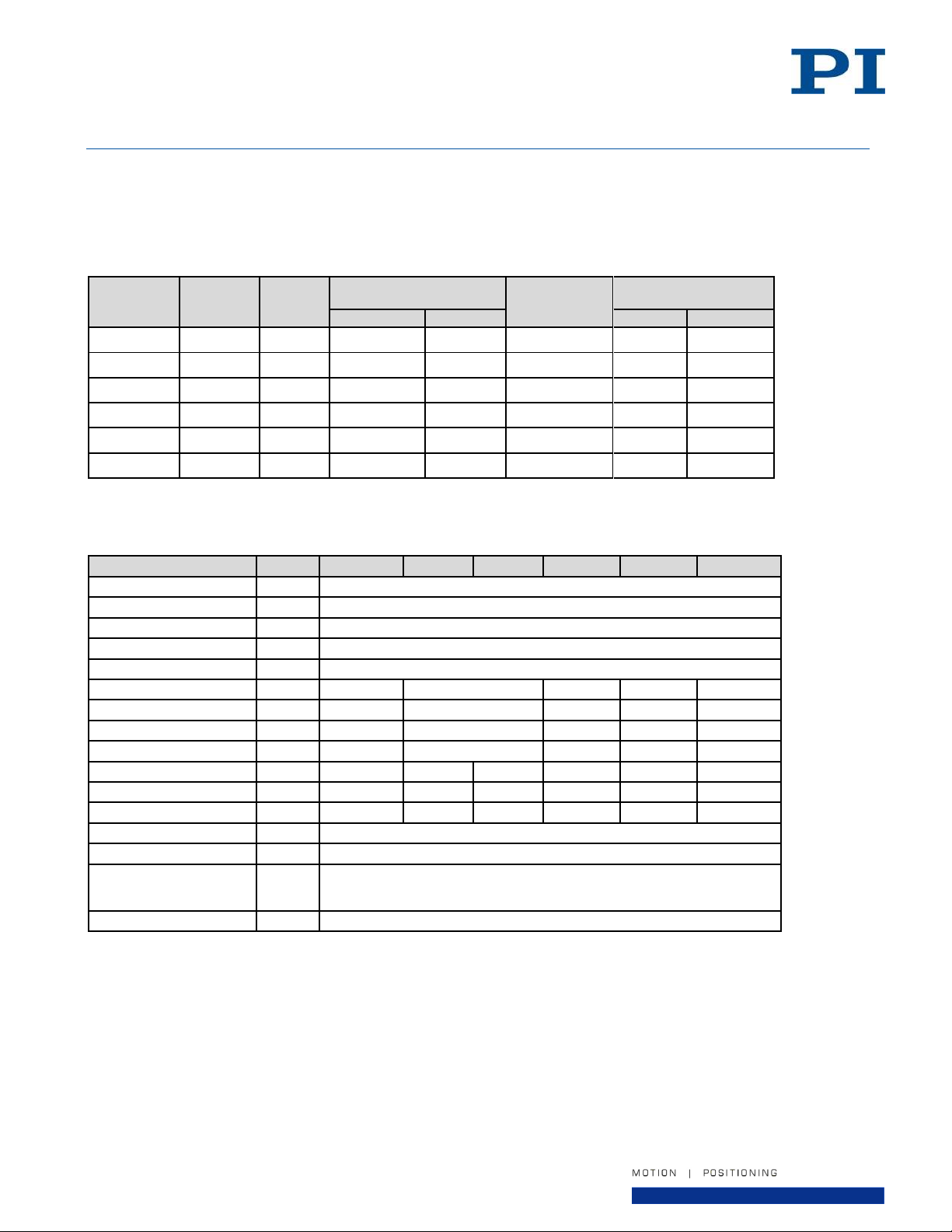
10.1. Sizes and Load Capacities
Values listed assume supply pressure of 80 psi. Please contact PI if alternate pressures are required.
10.2. Performance Specifications
Notes:
1. Values shown are obtained using controller-based error compensation. Stage must be purchased with a PI controller to achieve this
performance. Accuracy values assume short-term time duration and do not consider the long-term effects of thermal drift on the stage.
2. Precision specifications are dependent on quality of mounting surfaces, payload, orientation, and external forces on the stage. Please
consult PI for application-specific parameters. Values shown are static (zero rotational velocity during measurement) with no payload.
3. Velocity may be further limited by encoder options, payload imbalance, or controller and drive electronics.
4. To protect stage from damage, an under-pressure air sensor tied to the controller E-stop input is recommended.
5. Alternate custom tabletop materials, such as stainless steel, are available. Please contact PI for a quote.
Page 24 of 32
Page 25
User Manual
PI (Physik Instrumente) L.P.
16 Albert Street, Auburn, MA 01501
Tel: 508-832-3456 Fax: 508-832-0506
Email: [email protected]
Specification
Units
A-621.025
A-623.xxx
A-624.050
A-625.065
A-627.075
Motor Bus Voltage
VDC
48 VDC nominal, 80 VDC max
Motor Torque Constant
N-m/A
0.03
0.26
0.59
0.59
0.61
Continuous Current
Arms
3.3
3.1
2.3
2.3
4.5
Peak Current
Arms
10.3
9.5
6.9
6.9
13.9
Continuous Torque
N-m
0.07
0.7
1.57
1.57
2.82
Peak Torque
N-m
0.21
2.1
4.71
4.71
8.46
Motor Back EMF
V/kRPM
4.1
31.8
71
71
74
Motor Resistance
(phase-to-phase)
Ω
2.7
4.2
6.7
6.7
4.5
Motor Inductance
(phase-to-phase)
mH
0.1
0.4
0.9
0.9
0.6
# Poles - 12
28
48
48
64
Option Code A B
Type
Incremental
Absolute
Output Signal
Analog Quadrature
1 Vp-p, Differential
BiSS-C 32-bit serial
Power Input
5 VDC, <200 mA
5 VC, <250mA
Input Ripple
200 mVp-p max @ up to 500 kHz
Model
Option
Code
Units
A-621
A-623
A-624
A-625
A-627
Fundamental Lines/Rev
A # 8,192
15,744
23,600
31,488
47,200
Resolution
A
(1)
µrad
(arc-sec)
0.19
(0.04)
0.1
(0.02)
0.06
(0.01)
0.05
(0.01)
0.03
(0.007)
B
0.0015 (0.0003)
Max Velocity
A
RPM
See max velocity in table above. Not limited by encoder.
B
Index Mark
A
-
0.8 to 1.2 Vp-p, Differential, 1/rev
B
-
None
A620D0001 Rev 1.2
30-July-2019
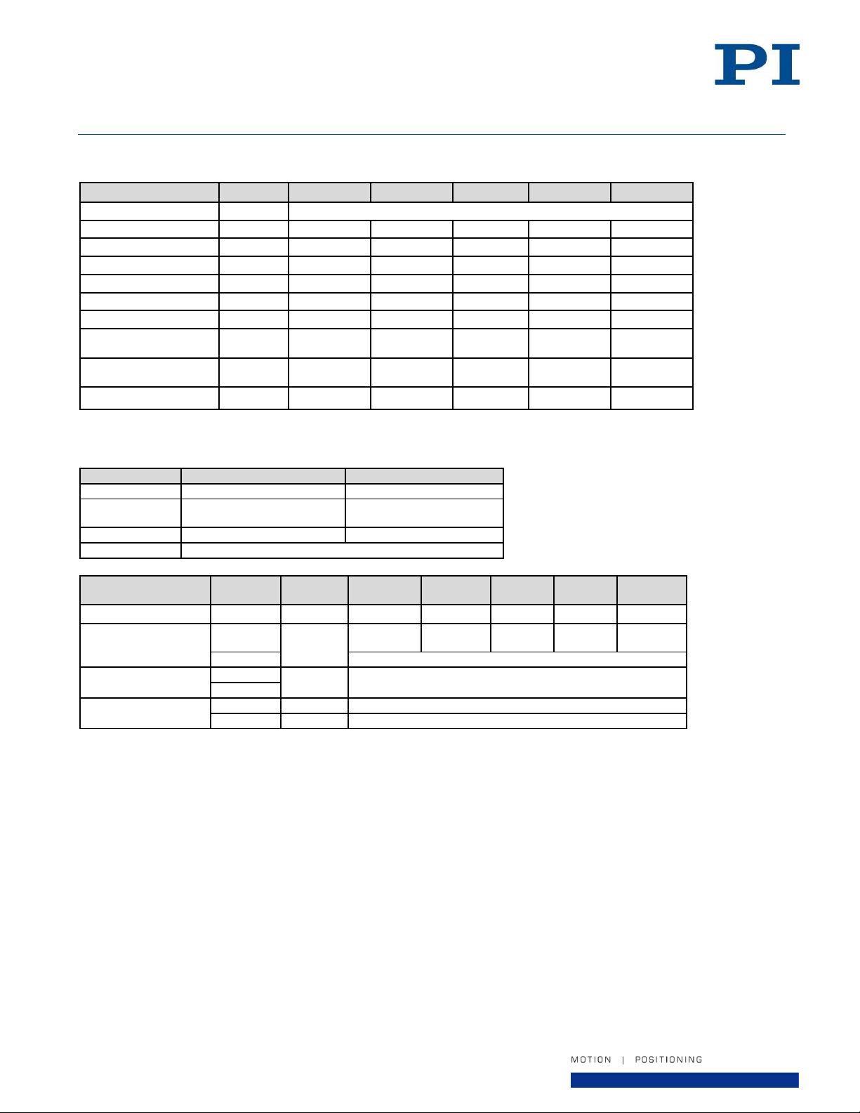
10.3. Motor Electrical Specifications
10.4. Encoder Specifications
Notes:
1. Resolution shown for encoder option “A” assumes 4096x interpolation.
Page 25 of 32
Page 26
User Manual
PI (Physik Instrumente) L.P.
16 Albert Street, Auburn, MA 01501
Tel: 508-832-3456 Fax: 508-832-0506
Email: [email protected]
Area of use
For indoor use only
Vacuum Operation
This product is not compatible with operation in a vacuum environment.
Maximum Altitude
2000m
Relative humidity
40% to 60% non-condensing
Operating temperature
(1)
+15°C to +25°C
Storage temperature
0°C to +40°C in original packaging
Dust Exposure
The stage is not suited for dusty, dirty, oily, or wet environments.
Overvoltage Category
II
Protection Class
I
Degree of Pollution
1
Degree of protection according to IEC
60529
IP20
A620D0001 Rev 1.2
30-July-2019
10.5. Ambient Conditions
Notes:
1. For optimum performance, the stage should be operated at 20°C. Any deviation from this temperature could degrade the precision and
performance of the stage. Any deviation outside the range shown above may damage the stage.
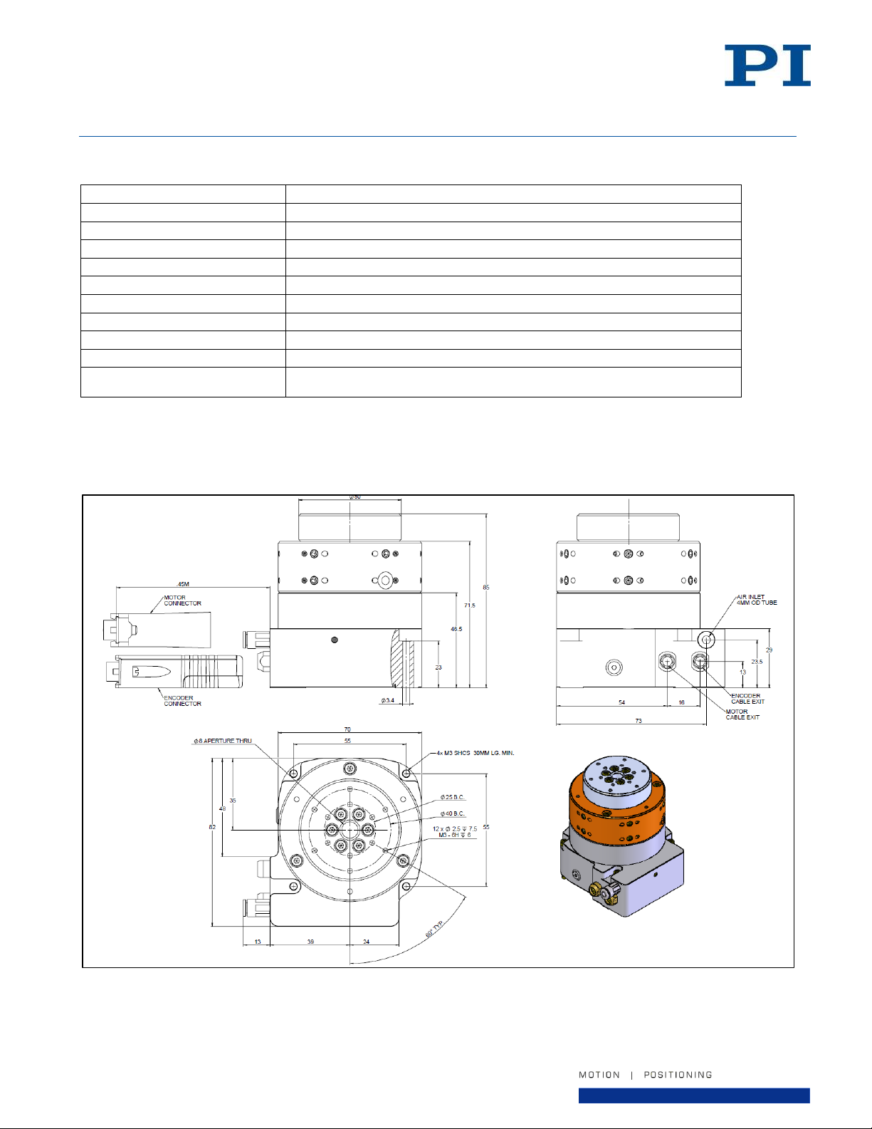
10.6. Dimensions
Figure 10 - A-621.025x1 Stage Dimensions
Page 26 of 32
Page 27
User Manual
PI (Physik Instrumente) L.P.
16 Albert Street, Auburn, MA 01501
Tel: 508-832-3456 Fax: 508-832-0506
Email: [email protected]
4MM OD TUBE
A620D0001 Rev 1.2
30-July-2019
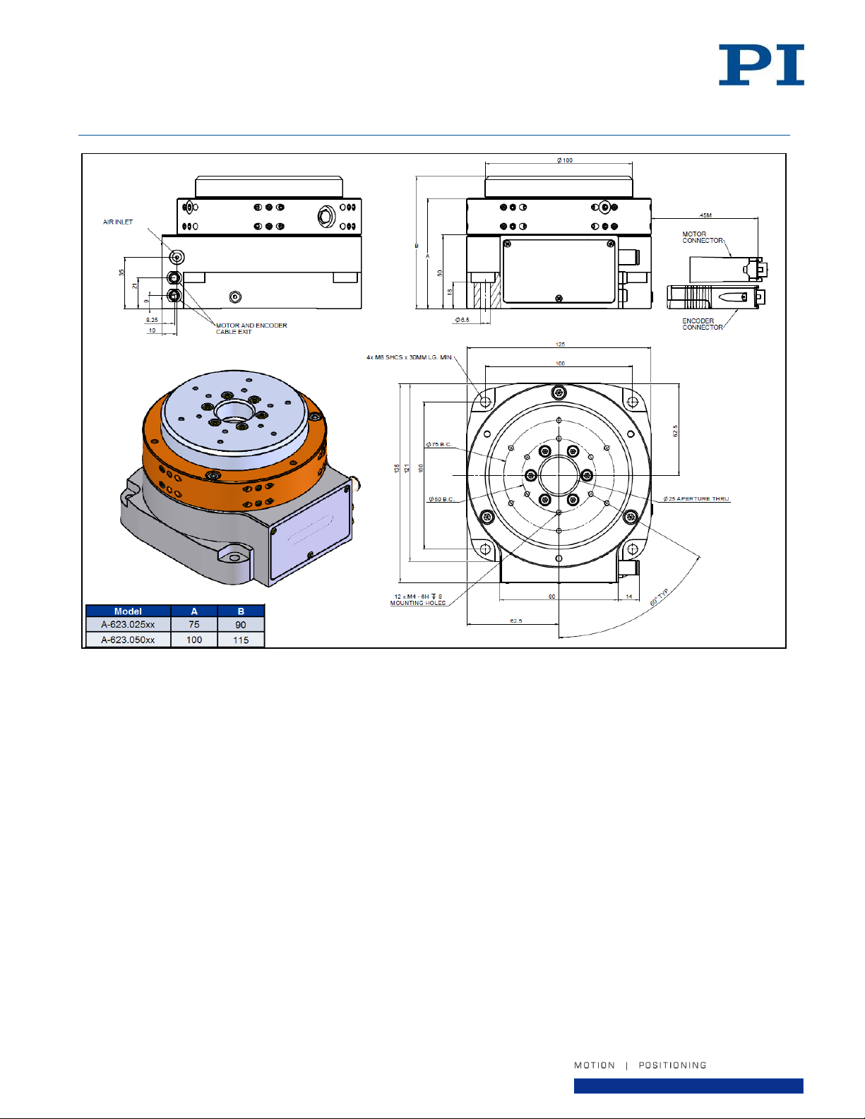
Figure 11 - A-623.xxxx1 Stage Dimensions
Page 27 of 32
Page 28
User Manual
PI (Physik Instrumente) L.P.
16 Albert Street, Auburn, MA 01501
Tel: 508-832-3456 Fax: 508-832-0506
Email: [email protected]
A620D0001 Rev 1.2
30-July-2019
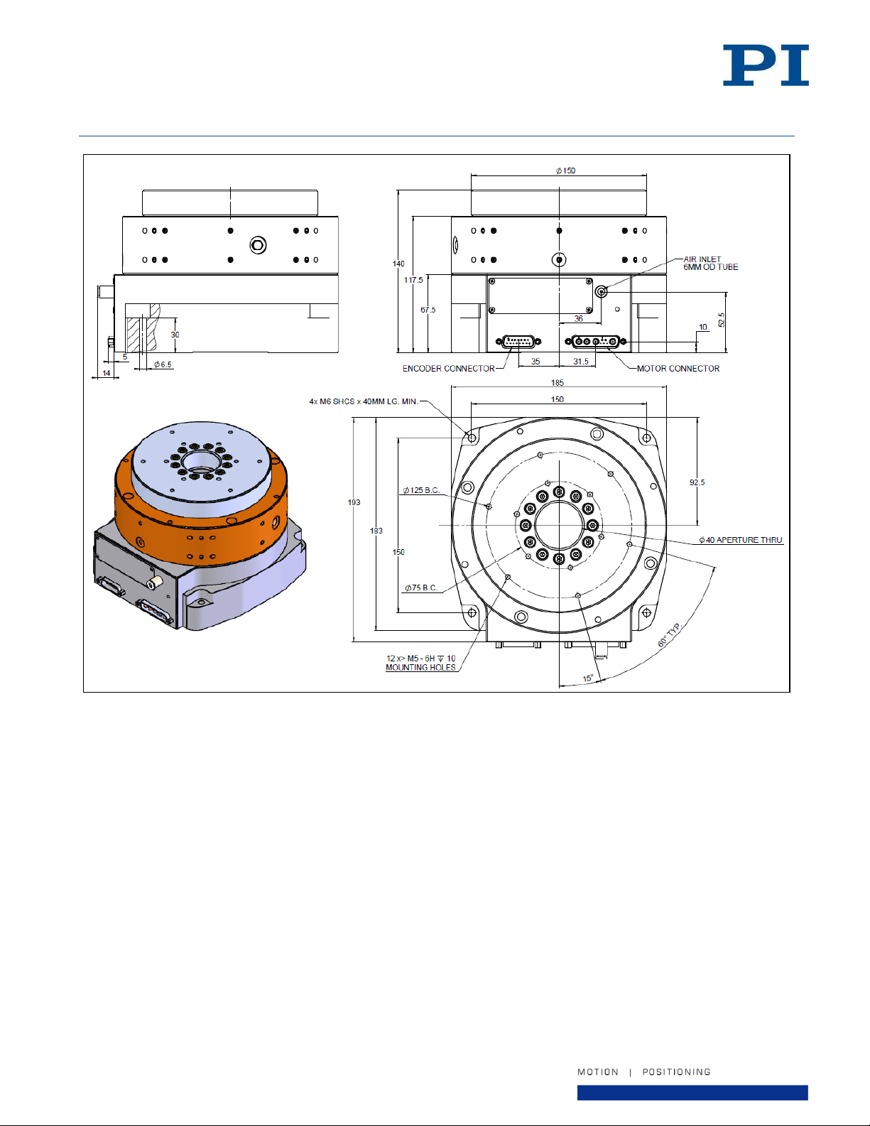
Figure 12 - A-624.050x1 Stage Dimensions
Page 28 of 32
Page 29
User Manual
PI (Physik Instrumente) L.P.
16 Albert Street, Auburn, MA 01501
Tel: 508-832-3456 Fax: 508-832-0506
Email: [email protected]
A620D0001 Rev 1.2
30-July-2019
Figure 13 - A-625.065x1 Stage Dimensions
Page 29 of 32
Page 30
User Manual
PI (Physik Instrumente) L.P.
16 Albert Street, Auburn, MA 01501
Tel: 508-832-3456 Fax: 508-832-0506
Email: [email protected]
A620D0001 Rev 1.2
30-July-2019
Figure 14 - A-627.075x1 Stage Dimensions
Page 30 of 32
Page 31
User Manual
PI (Physik Instrumente) L.P.
16 Albert Street, Auburn, MA 01501
Tel: 508-832-3456 Fax: 508-832-0506
Email: [email protected]
Pin
Function
Description
A1
PHA
Motor phase A
A2
PHB
Motor phase B
A3
PHC
Motor phase C
Pin
Function
Description
1
Cos-
Encoder Analog Cosine -
2
Sin-
Encoder Analog Sine -
3
Index+
Encoder Analog Reference +
4
+5v
Encoder power
5
+5v Sense
Encoder power sense line
6
Vx
Encoder Setup
7
Lim+
Open collector Limit+
8
Lim-
Open collector Limit-
9
Cos+
Encoder Analog Cosine +
10
Sin+
Encoder Analog Sine +
11
Index -
Encoder Analog Reference -
12
GND
Encoder ground
13
GND Sense
Encoder ground sense line
14
CAL
Encoder Calibration
Pin
Function
Description
2
MA+
Encoder CLK+ (MA+)
3
MA-
Encoder CLK- (MA-)
4
+5v
Encoder power
5
+5v
Encoder power
6
SLO+
Encoder Data+ (SLO+)
7
SLO-
Encoder Data- (SLO-)
8
GND
Encoder ground
9
GND
Encoder ground
A620D0001 Rev 1.2
30-July-2019
10.7. Pin Assignments
Pins are assumed to be “N/C” if not shown.
Motor Connector
Type: DB9W4M
Encoder Connector, Encoder Option “A”
Type: DB15M
Encoder Connector, Encoder Option “B”
Type: DB15M
Page 31 of 32
Page 32

User Manual
PI (Physik Instrumente) L.P.
16 Albert Street, Auburn, MA 01501
Tel: 508-832-3456 Fax: 508-832-0506
Email: [email protected]
A620D0001 Rev 1.2
30-July-2019
11. EC Declaration of Conformity
For the model A-62x (all options and configurations), an EC Declaration of Conformity has been issued in
accordance with the following European directives:
2004/108/EC, EMC Directive
2014/35/EU, Safety/Low Voltage Directive
2011/65/EU, RoHS Directive
The applied standards certifying the conformity are listed below.
EMC: EN 61326-1:2013
Safety/LVD: EN 61010-1:2010
RoHS: EN 50581:2012
If an electrical operating device is designed to be integrated in another electrical operating device: The operator
is responsible for a standards compliant integration of the electrical device into the overall system.
12. Old Equipment Disposal
In accordance with EU law, electrical and electronic equipment may not be disposed of in EU member states via
the municipal residual waste.
Dispose of your old equipment according to international, national, and local rules and regulations.
In order to fulfil its responsibility as the product manufacturer, Physik Instrumente (PI) GmbH & Co. KG
undertakes environmentally correct disposal of all old PI equipment made available on the market after 13
August 2005 without charge.
Any old PI equipment can be sent free of charge to the following addresses:
Physik Instrumente (PI) GmbH & Co. KG
Auf der Roemerstr. 1
D-76228 Karlsruhe
Germany
PI (Physik Instrumente) L.P.
16 Albert Street
Auburn, MA 01501
USA
Page 32 of 32
 Loading...