

1
www.phywe.com, © All rights reserved 13607-99 / 0317
Operating instructions
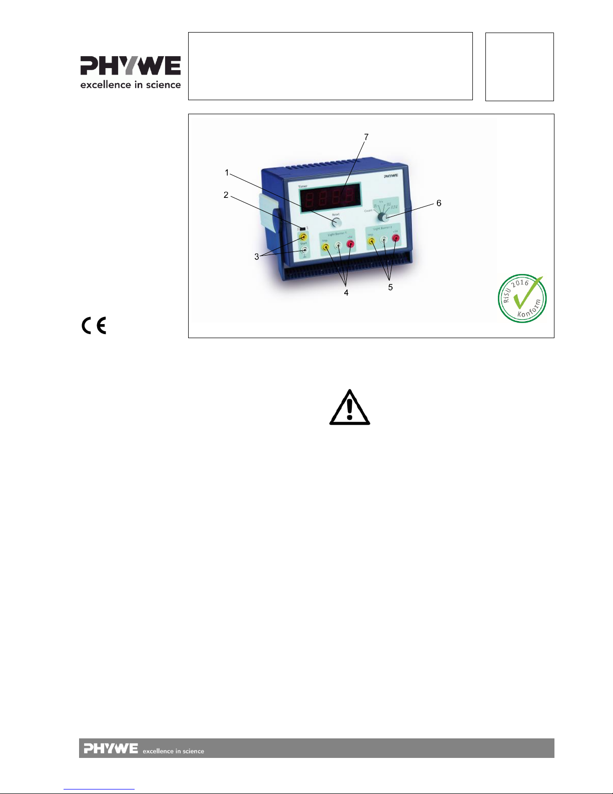
Fig. 1: Timer 2-1, 13607-99
Timer 2-1
13607-99
PHYWE Systeme GmbH & Co. KG
Robert-Bosch-Breite 10
D–37079 Göttingen
Telefon +49 (0) 551 604–0
Fax +49 (0) 551 604–107
E-mail info@phywe.de
Internet www.phywe.com
The unit complies
with the corresponding EU guidelines.
TABLE OF CONTENTS
1 SAEFTY PRECAUTIONS
2 PURPOSE AND DESCRIPTION
3 EXPLANATION OF THE SYMBOLS
4 FUNCTIONAL AND OPERATING ELEMENTS
5 HANDLING
6 NOTES ON OPERATION
7 TECHNICAL DATA
8 SCOPE OF DELIVERY
9 LIST OF EQUIPMENT
10 WASTE DISPOSAL
1 SAEFTY PRECAUTIONS
Carefully read these operating instructions completely be-
fore operating this instrument. This is necessary to avoid
damage to it, as well as for user-safety.
Check that your mains supply voltage corresponds to that
given on the type plate fixed to the instrument.
Install the instrument so that the on/off switch and the
mains connecting plug are easily accessible. Do not
cover the ventilation slits.
Take care that no liquids or objects enter in through the
ventilation slots.
Only use the instrument in dry rooms in which there is no
risk of explosion.
Only use the instrument for the purpose for which it was
designed.
Protect the instrument from dust, moisture and vapours.
Only clean it in voltage-free state with a slightly
moistened, lint-free cloth. Aggressive cleaning agents and
solvents are unsuitable.
Do not operate if there are visible signs of damage to the
unit, the connection cord or the measuring lines.
Do not open the unit.
Do not connect any devices to the unit other than the
ones that are intended for this purpose.
Only use the power supply that is supplied with the unit
(Order.-No. 12651-99).
Attention!

2
www.phywe.com, © All rights reserved 13607-99 / 0317
2 PURPOSE AND DESCRIPTION
The chronometer Timer 2-1 has a 4-digit digital display and
has been specially designed for use in student experiments
and demonstrative teacher experiments. The starting and
stopping of the built-in timer piece, as well as counting, is effected by the opening and closing of electrical circuits, across
light barriers or other TTL signal sources.
Many and various experimental requirements can be fulfilled
with the 4 different operating modes that the Timer 2-1 makes
available for track experiments, for the measurement of the
time of revolution of a turning movement, for the direct measurement of the period of a full swing of a mechanical pendulum and for the counting of events.
3 EXPLANATION OF THE SYMBOLS
The safety isolating transformer and safe
isolation in accordance with
DIN EN 61558-2-16 of the connected power supply unit 12651-99 ensure that the
regulations for safety at schools (Richtlinien für Sicherheit im Unterricht (RiSU)) in
line with the recommendation of the Standing Conference of the Ministers of Education and Cultural Affairs of the Länder in the Federal Republic of Germany are
fulfilled.
4 FUNCTIONAL AND OPERATING ELEMENTS
The instrument is fitted in an impact-resistant plastic housing,
the single carrying handle of which can be swung down to act
as an inclining prop. Four rubber feet ensure slip-resistance
and standing stability. The instrument can be stacked with
other instruments that have the same type of housing, whereby the rubber feet fit into pan-shaped depressions in the instrument housing below to provide increased security against
displacement. The inclined housing position is only permissible for the top housing in a stack. The power supply unit (article no. 12651-99) that is standardly supplied with the instrument serves to connect it to the AC-mains when it is connected to the back of the instrument via the instrument connecting
plug. All other functional and operating elements are to be
found at the front of the instrument (see Fig. 1).
1 Reset button
for resetting the display to zero and to restore readiness for
measurement prior to each new measurement.
2 Slide switch
or selection of the trigger signal edge for the input Start; position : Start of measurement by the rising edge of a TTLpulse (enabling of a light barrier) or by opening the electrical
connection between the sockets of the corresponding input;
position : Start of measurement by the descending edge of
a TTL-pulse (interrupting of a light barrier) or by closing the
electrical connection between the sockets of the corresponding input.
Note: Should no external trigger be connected to the Start
socket, then the slide switch should be in the position ,
as otherwise the instrument will not operate as expected
in all operating modes.
3 Start pair of sockets
or starting time measurement in operating modes
and ; (see section 4 for a description of the operating
modes). The signal can hereby be generated through a light
barrier or a mechanical starter by the opening or closing of an
external contact.
4, 5 Connecting socket for fork light barriers
for the operation of two fork light barriers. The light barriers
are supplied with a 5 VDC operating voltage. Control input
sockets (Imp.) serve to start and/or stop a time measurement
according to the operating mode that has been selected with
switch 6. The reference terminal for each control input socket
is the socket marked "Mass". The mode of action of the control inputs is dependent on the selected operating mode (see
section 4).
6 Rotary switch
for the selection of one of the 4 available operating modes
(see section 4).
7 Digital display
for the display of times measured within the range from 0.000
to 9.999 s, or of the number of counts of events from 0 to
9999.
8 Gate LED
when this LED lights up, it shows that a time measurement
and the internal clock have been started. This function is most
helpful in indicating an inadvertent triggering of timer 2 - 1.
5 HANDLING
When the operating voltage is applied, a press on the reset
button makes the timer ready for use. The operating mode
that is most suitable for the experiment that is to be carried
out is to be selected from described in section 4. Control instruments must be connected to the control input of the timer
for time measurements to be started and stopped. Select the
most suitable of these from the List of Equipment. Should instruments that are not in the list to be connected, first check
that their control signals correspond to the TTLNorm.
An automatic repeat-lock ensures that no measured time value can be unintentionally overwritten. To regain readiness for
a new measurement, press the reset button to put back the
display. A running measurement can be stopped at any time
with the reset button.
Description of the operating modes
Rotary switch 6 allows one of the four available operating
modes to be selected. Graphic symbols on the front plate
mark the switch positions.
For all operating modes, first select the one wanted with
rotary switch 6, then press the reset button. The previous
operating mode is only brought to an end after this is
done.
5.1 Pulse counting
— Turn rotary switch 6 to the "Count" position.
— Press the reset button.
The display shows readiness for measurement with 0000.
A light barrier at the "Light Barrier 1" connection now counts
the number of shadings.
5.2 Measurement of the time period during shading
— Turn rotary switch 6 to the „ “ position.
— Press the reset button.
After the pressing of the reset button, the display shows two
decimal points which confirm readiness for measurement.

3
www.phywe.com, © All rights reserved 13607-99 / 0317
The shading period of a light barrier that is connected either at
"Light Barrier 1" or at "Light Barrier 2" is measured and displayed. Two light barriers can also be simultaneously connected. The shading time of the light barrier that is first interrupted is then measured.
Measurement range: 0 to 9.999 s. Renewed measurement
possible, but only after first pressing the reset button.
5.3 Measurement of the time period between the start of
two shadings
— Turn rotary switch 6 to the " " position.
— Press the reset button.
After the pressing of the reset button, the display shows three
decimal points which confirm readiness for measurement.
The time period between two shadings is measured and displayed. This operating mode is particularly suitable for track
experiments to determine the time that a car takes to travel
the distance between two light barriers.
Alternatively, the timer can be started by a signal at the "Start"
input according to the selected signal edge and be stopped by
the shading of a connected light barrier. Measurement range
0 to 9.999 s. Renewed measurement possible, but only after
first pressing the reset button.
5.4 Measurement of the time period between the start of
the first and the third shadings
— Turn rotary switch 6 to the „ “ position.
— Press the reset button.
After the pressing of the reset button, the display shows four
decimal points which confirm readiness for measurement.
The time period between the first and third shading is measured and displayed. This enables, for example, the complete
period of swing of a pendulum to be measured with one light
barrier. It is hereby of no importance which light barrier input
is used. The time between the beginning of the first and the
third shading is displayed, regardless of with which light barrier the shadings occur.
Alternatively, the timer is started by a signal at the "Start" input according to the selected signal edge and stopped at the
beginning of the second shading of a connected light barrier.
Measurement range 0 to 9.999 s. Renewed measurement
possible, but only after first pressing the reset button.
6 NOTES ON OPERATION
This high-quality instrument fulfills all of the
technical requirements that are complied in
current EC guidelines. The characteristics of
this product qualify it for the CE mark.
This instrument is only to be put into operation under specialist supervision in a controlled electromagnetic environment in
research, educational and training facilities (schools, universities, institutes and laboratories).
This means no mobile phones etc. are to be used in the near
vicinity. The individual connecting leads must not be longer
than 2 m.
The Instrument can be influenced by electromagnetic charges
and other electromagnetic phenomena in such way, that it
works no longer within the given specifications. The following
measures reduce or prevent disturbing influences: Avoid carpeted floor ensure potential equalization, perform the experiments on conductive and grounded surfaces, use screenings
and screened cables and do not work with high frequency
emitters ( radios, mobile phones etc.) in the immediate vicinity. After a total blackout, carry out a "Reset" (new start) of the
complete system.
7 TECHNICAL DATA
Operating temperature range 5-40°C
Relative humidity <80 %
Control Start/Stop) by electrical cir-
cuits (contact closure/contact
opening or level acc. To TTLNorm)
Digital display 4-Digit LED display, digit
height 19 mm
Time measurement Measuring range
0,000...9,999 s
resolution1 ms
Pulse counting Measurement range 0…9999
pulses
Limiting frequency 1 kHz,
shading period > 500 μs
Operating voltage (Stabilized) 5 V±5%
(suitable power supply
5 VDC/2.4 A, 13900-99
standardly supplied)
Power consumption 1.8 VA
Supply connector Connecting socket for hollow
plug, diam. 2.1 mm at the
back of the instrument
5 VDC/350 mA
Overvoltage and reverse up to max. 12 V
polarity protection
Housing dimensions (mm) 206 × 130 × 160 (W, H, D)
Weight approx. 920 g
8 SCOPE OF DELIVERY
Timer 2-1 13607-99
Power supply 5 VDC/4 A 12651-99
9 LIST OF EQUIPMENT
The timer can only be used in combination with suitable control instruments that can be connected to its inputs. All instruments are suitable that open or close a switch contact or supply an electrical pulse and conform to TTL-Norm. The following list provides a selection of instruments that can be connected to inputs 3, 4 and 5:
Falling sphere apparatus 02502-88
Holding device with cable release 02417-04
Starter system, mechanical with release 11202-13
Fork light barrier, compact 11207-20
Push button switch, circuit closing 06039-00
10 WASTE DISPOSAL
The packaging mainly consists of environmentally-friendly
materials that should be returned to the local recycling stations.
PHYWE Systeme GmbH & Co. KG
Customer Service
Robert-Bosch-Breite 10
D–37079 Göttingen
Germany
Telephone +49 (0) 551 604-274
Fax +49 (0) 551 604-246
Do not dispose of this product with normal
household waste. If this unit needs to be
disposed of, please return it to the address
that is stated below for proper disposal.
 Loading...