

Page 1

phyCORE-LPC2294
QuickStart Instructions
Using Keil's ULINK and the Keil ARM7/µVision3
Software Development Tool Chain
Note: The PHYTEC Spectrum CD includes the electronic version of
the English phyCORE-LPC2292/94 Hardware Manual
Edition: June 2005
A product of a PHYTEC Technology Holding company
Page 2

phyCORE-LPC2294 QuickStart Instructions
In this manual are descriptions for copyrighted products that are not explicitly
indicated as such. The absence of the trademark ( ) and copyright () symbols
does not imply that a product is not protected. Additionally, registered patents and
trademarks are similarly not expressly indicated in this manual.
The information in this document has been carefully checked and is believed to be
entirely reliable. However, PHYTEC Messtechnik GmbH assumes no
responsibility for any inaccuracies. PHYTEC Messtechnik GmbH neither gives
any guarantee nor accepts any liability whatsoever for consequential damages
resulting from the use of this manual or its associated product. PHYTEC
Messtechnik GmbH reserves the right to alter the information contained herein
without prior notification and accepts no responsibility for any damages which
might result.
Additionally, PHYTEC Messtechnik GmbH offers no guarantee nor accepts any
liability for damages arising from the improper usage or improper installation of
the hardware or software. PHYTEC Messtechnik GmbH further reserves the right
to alter the layout and/or design of the hardware without prior notification and
accepts no liability for doing so.
Copyright 2005 PHYTEC Messtechnik GmbH, D-55129 Mainz.
Rights - including those of translation, reprint, broadcast, photomechanical or
similar reproduction and storage or processing in computer systems, in whole or in
part - are reserved. No reproduction may occur without the express written
consent from PHYTEC Messtechnik GmbH.
EUROPE NORTH AMERICA
Address: PHYTEC Technologie Holding AG
Robert-Koch-Str. 39
D-55129 Mainz
GERMANY
Ordering
Information:
Technical
Support:
Fax: +49 (6131) 9221-33 1 (206) 780-9135
Web Site: http://www.phytec.de http://www.phytec.com
+49 (800) 0749832
+49 (6131) 9221-31
PHYTEC America LLC
203 Parfitt Way SW, Suite G100
Bainbridge Island, WA 98110
USA
1 (800) 278-9913
1 (800) 278-9913
3rd Edition: June 2005
© PHYTEC Meßtechnik GmbH 2005 L-659e_3
Page 3

Contents
1 Introduction to the Rapid Development Kit.....................................1
1.1 Rapid Development Kit Documentation ......................................1
1.2 Overview of this QuickStart Instruction.......................................2
1.3 System Requirements ...................................................................3
1.4 The PHYTEC phyCORE
1.5 Keil ARM7/µVision3 Software Development Tool Chain..........7
2 Getting Started.....................................................................................9
2.1 Installing Rapid Development Kit Software.................................9
2.2 Interfacing the phyCORE
2.3 Downloading Example Code with Philips LPC2000
Flash Utility................................................................................18
2.4 Downloading Example Code with µVision3..............................21
2.4.1 "Blinky".........................................................................22
2.4.2 "Hello"...........................................................................25
3 Getting More Involved......................................................................31
3.1 Creating a New Project and Adding an Existing Source File.....31
3.1.1 Configure the Project Components................................33
3.1.2 Adding Source Files to the Project................................37
3.2 Modifying the Source Code........................................................40
3.3 Setting Options for Flash Target ................................................41
3.4 Building the Project....................................................................52
3.5 Downloading Code into Flash Memory......................................53
-LPC2294...........................................4
-LPC2294 to a Host-PC...................15
4 Debugging...........................................................................................55
4.1 Creating a Debug Project and Preparing the Debugger..............56
4.1.1 Creating a New Project..................................................56
4.1.2 Setting Options for Target.............................................57
4.2 Starting the Debugger.................................................................65
4.3 Keil µVision3 Debug Features ...................................................67
4.4 Using the Keil µVision3 Debug Features...................................69
4.4.1 Breakpoints....................................................................69
4.4.2 Single Stepping and Watch Window.............................70
4.5 Running, Stopping and Resetting...............................................71
4.6 Changing Target Settings for the "Executable Version"............72
© PHYTEC Meßtechnik GmbH 2005 L-659e_3
Page 4

phyCORE-LPC2294 QuickStart Instructions
Index of Figures
Figure 1: Default Jumper Settings of the phyCORE Development
Board HD200 with phyCORE
Figure 2: JTAG Connector X701 on the phyCORE
(Bottom View)........................................................................... 16
Figure 3: ULINK Connected to the phyCORE
Figure 4: Power Connector .......................................................................17
-LPC2294................................15
-LPC2294
Module .........................17
© PHYTEC Messtechnik GmbH 2005 L-659e_3
Page 5

1 Introduction to the Rapid Development Kit
This QuickStart provides:
Introduction
• general information on the PHYTEC phyCORE
Board Computer (SBC),
• an overview of Keil's ARM7/µ Vision3 software development tool
chain evaluation version, and
• instructions on how to run example programs on the
phyCORE
-LPC2294, mounted on the PHYTEC phyCORE
Development Board HD200, in conjunction with the Philips
LPC2000 Flash Utility for internal Flash, the Keil ULINK and
software tools
-LPC2294 Single
Please refer to the phyCORE
-LPC2292/94 Hardware Manual for
specific information on such board-level features as jumper
configuration, memory mapping and pin layout. Selecting the links on
the electronic version of this document links to the applicable section
of the phyCORE
-LPC2292/94 Hardware Manual.
1.1 Rapid Development Kit Documentation
This "Rapid Development Kit" (RDK) includes the following
electronic documentation on the enclosed "PHYTEC Spectrum
CD-ROM":
• the PHYTEC phyCORE
• controller User's Manuals and Data Sheets
• this QuickStart Instruction with general "Rapid Development Kit"
description, software installation hints and three example programs
enabling quick out-of-the box start-up of the phyCORE
in conjunction with the Keil ARM7/µVision3 software
development tool chain
-LPC2292/94 Hardware Manual
-LPC2294
© PHYTEC Messtechnik GmbH 2005 L-659e_3 1
Page 6

phyCORE-LPC2294 QuickStart Instructions
1.2 Overview of this QuickStart Instruction
This QuickStart Instruction gives a general "Rapid Development Kit"
description, as well as software installation hints and three example
programs enabling quick out-of-the box start-up of the
phyCORE
ARM7/µVision3 software tools. It is structured as follows:
1) The "Getting Started" section uses three examples:
2) The "Getting More Involved" section provides step-by-step
-LPC2294 in conjunction with the Keil ULINK and
Blinky to demonstrate the download of user code to the internal
Flash device using the Philips LPC2000 Flash Utility
Blinky and Hello to demonstrate the download of user code to
the external Flash device using the Keil ULINK and
ARM7/µVision3 software tools
instructions on how to modify both examples, create and build
new projects and generate and download output files to the
phyCORE
-LPC2294 using the Keil tools.
3) The "Debugging" section provides a third example
program - "Debug" - to demonstrate simple debug functions
using the Keil µVision3 debug environment.
In addition to dedicated data for this Rapid Development Kit, the
PHYTEC Spectrum CD-ROM contains supplemental information on
embedded microcontroller design and development.
2 © PHYTEC Messtechnik GmbH 2005 L-659e_3
Page 7

1.3 System Requir ements
Use of this "Rapid Development Kit" requires:
Introduction
• the PHYTEC phyCORE
• the phyCORE
Development Board HD200 with the included
-LPC2294
DB-9 serial cable and AC adapter supplying 5 VDC /min. 500 mA
• the Philips LPC2000 Flash Utility software
• the Keil ULINK JTAG-USB adapt er, not included in the standard
Rapid Development Kit version
1
• the PHYTEC Spectrum CD for ARM7
• an IBM-compatible host-PC (486 or higher running at least
Windows95/NT)
For more information and example updates, please refer to the
following sources:
http://www.keil.com
[email protected]
1
: The Keil ULINK is included in the Rapid Development Kit version with the part number
KPCM-023-SK-2294-Keil.
© PHYTEC Messtechnik GmbH 2005 L-659e_3 3
Page 8

phyCORE-LPC2294 QuickStart Instructions
1.4 The PHYTEC phyCORE-LPC2294
The phyCORE-LPC2294 represents an affordable yet highly
functional Single Board Computer (SBC) solution in sub-miniature
dimensions (60 x 53 mm). It is intended for use in memory-intensive
applications running within a multi-node CAN bus system. The
standard module is populated with a Philips LPC2294 controller.
All applicable data/address lines and signals extend from the
underlying logic devices to two high-density Molex SMT pin header
connectors (pin width is 0.635 mm/25 mil) lining the circuit board
edges. This enables the phyCORE
"big chip" into target hardware.
The standard module runs at a 60 MHz internal clock speed
(delivering 50/10 ns instruction cycle) and offers 1 MByte (up to
8 MByte) SRAM and 2 MByte (up to 16 MByte) Flash on-board for
DATA and CODE storage.
-LPC2294 to be plugged like a
The module communicates by means of two RS-232 transceivers,
two (four optional) CAN bus interfaces, and a SMSC LAN91C111
10/100BaseT Ethernet controller which enables implementation of the
module in embedded Internet applications. The
phyCORE
-LPC2294 operates within a temperature range of -40°C to
+85°C and requires only a 300 mA power source.
The Keil ARM/µVision3 software tools, in conjunction with the Keil
ULINK adapter, enables easy on-board download of user programs.
4 © PHYTEC Messtechnik GmbH 2005 L-659e_3
Page 9

Introduction
The phyCORE
-LPC2294 offers the following features:
• subminiature Single Board Computer (60 x 53 mm) achieved
through modern SMD technology
• populated with the Philips LPC2294 microcontroller
(TQPF-144 packaging)
• improved interference safety achieved through multi-layer PCB
technology and dedicated Ground pins
• controller signals and ports extend to two 100-pin high-density
(0.635 mm) Molex connectors aligning two sides of the board,
enabling it to be plugged like a "big chip" into target application
• 32-bit, demultiplexed bus mode
• max. 60 MHz clock frequency (ca. 50 ns instruction cycle,
external; ca. 10 ns internal Flash)
• 1.5 Gbyte external address space
• 2 MByte (up to 16 MByte) on-board Flash
1
• on-board Flash programming, no dedicated Flash programming
voltage required through use of 3.3 V Flash devices
• 1 MByte (up to 8 MByte) RAM on-board, max. 2 MByte at 0 wait
states
1
• up to two CAN transceivers (Infineon TLE6250V 33)
• RS-232 transceiver for two serial interfaces
• SMSC 91C111 Ethernet controller with configuration EEPROM
• 2 kByte (up to 8 kByte) SPI-EEPROM
1
• I2C Real-Time Clock with internal quartz (can be battery buffered)
• one operating voltage for core & peripherals, 3.3 V,
typ. < 280 mA
• controller 1.8 V core voltage generated on-board
• additional 5 V operating voltage for CAN transceivers,
typ. <12 mA
• support of LPC2294 single chip mode
1
: Please contact PHYTEC for more information about additional module configurations.
© PHYTEC Messtechnik GmbH 2005 L-659e_3 5
Page 10

phyCORE-LPC2294 QuickStart Instructions
The phyCORE Development Board HD200, in EURO-card
dimensions (160 x 100 mm) is fully equipped with all mechanical and
electrical components necessary for the speedy and secure insertion
and subsequent programming of most PHYTEC phyCORE
highdensity series Single Board Computers. Simple jumper configuration
readies the Development Board’s connection to the
phyCORE
-LPC2294, which plugs into the receptacle contact strips
mounted on the Development Board HD200.
phyCORE
Development Board HD200 Technical Highlights
• low voltage socket for supply with regulated input voltage 5 VDC
• additional supply voltages 3.3 VDC or 2.5 VDC
• two DB-9 sockets (P1A, P1B) configurable as RS-232 interfaces
• two additional DB-9 plugs (P2A, P2B) configurable as
CAN interfaces
• simple jumper configuration allowing use of the
phyCORE
phyCORE
Development Board HD200 with various PHYTEC
high-density SBCs
• socket for RJ45 Ethernet transformer module
• one control LED (D3) for quick testing of user software
• 2x 160-pin Molex connector (X2) enabling easy connectivity to
expansion boards (e.g. PHYTEC GPIO Expansion Board)
6 © PHYTEC Messtechnik GmbH 2005 L-659e_3
Page 11

1.5 Keil ARM7/µVision3 Software Development Tool C hain
Keil Software development tools for the ARM7 TDMI Architecture
support every level of developer from the professional applications
engineer to the student just learning about embedded software
development. The Keil ARM7 compiler supports all ARM7compatible devices including the Philips LPC2000 devices. For a
complete list of supported ARM7 derivatives go to:
http://www.keil.com/dd/arm7chips.asp
µ Vision3, the latest version of Keil's popular IDE, combines project
management, source code editing, program debugging, and Flash
programming in a single, powerful environment. This QuickStart
provides an overview of the most commonly used µVision3 features
including:
Introduction
• Project management, device setup, and tool configuration
• Integrates Keil ARM development tools in a single graphical user
interface (GUI)
• Editor facilities for creating, modifying, and correcting programs
• JTAG/target debugging or CPU & peripheral simulation
Once installed, the default destination location for all ARM7 tools;
executables; include, header and example files; as well as online help
and documentation is the C:\Keil\Arm folder, while the µVision3 IDE
is located at C:\Keil\Uv3. You can start Keil µ Vision3 by selecting it
from the Programs menu using the Windows Start button. The Keil
µ Vision3 icon will also be placed on your desktop for easy startup of
the development tools.
© PHYTEC Messtechnik GmbH 2005 L-659e_3 7
Page 12

phyCORE-LPC2294 QuickStart Instructions
The new µVision3 editor offers many standard and advanced software
editing features like:
• Incremental Find positions the cursor while you type the search
phrase.
• Active Brace Checking shows nesting and highlights mismatches
while entering parentheses, braces, or brackets.
• Text Block Functions that comment, indent, uppercase, tabify,
and remove whitespace from text blocks.
• Document-Selective Settings for tab spacing and syntax coloring
in Assembler, C, and other file ty pes.
• Detailed Syntax Highlighting that allows you to define a user
keyword list. Colors are used in printed output.
• Document Outlining that provides a quick overview of complex
source files.
The ARM7 evaluation version, as provided on the PHYTEC
Spectrum CD, has the following limitations:
• The µVision Debugger is limited to 16 kBytes.
• You may not use the Evaluation Version of the µVision
IDE/Debugger to create commercial products.
• The GNU ARM tools (compiler, assembler, and so on) that are
provided are not limited or restricted in any way.
The full DKARM Developer's Kit can be purchased through
PHYTEC. Please contact our sales representatives for a quote.
For more information on Keil ARM7/µVision3 tools visit their
website at:
http://www.keil.com/arm/
8 © PHYTEC Messtechnik GmbH 2005 L-659e_3
Page 13

2 Getting Started
What you will learn with this Getting Started example:
• installing Rapid Development Kit software
• interfacing the phyCORE-LPC2294, mounted on the
Development Board, to a host-PC using the Keil ULINK
• downloading example user code in hex-file format from a host-PC
to the internal Flash memory using the Philips LPC2000 Flash
Utility
• downloading example user code from a host-PC to the external
Flash memory using ARM7/µVision3 tools
2.1 Installing Rapid Development Kit Software
Getting Started
When you insert the PHYTEC Spectrum CD into the CD-ROM drive
of your host-PC, the PHYTEC Spectrum CD should automatically
launch a setup program that installs the software required for the
Rapid Development Kit as specified by the user. Otherwise the setup
program start.exe can be manually executed from the root directory of
the PHYTEC Spectrum CD.
© PHYTEC Messtechnik GmbH 2005 L-659e_3 9
Page 14
phyCORE-LPC2294 QuickStart Instructions
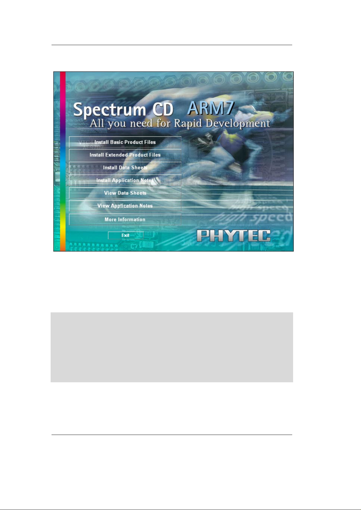
The following window appears:
• Choose Install Basic Product Files Button.
• After accepting the Welcome window and license agreement select
the destination location for installation of Rapid Development Kit
software and documentation.
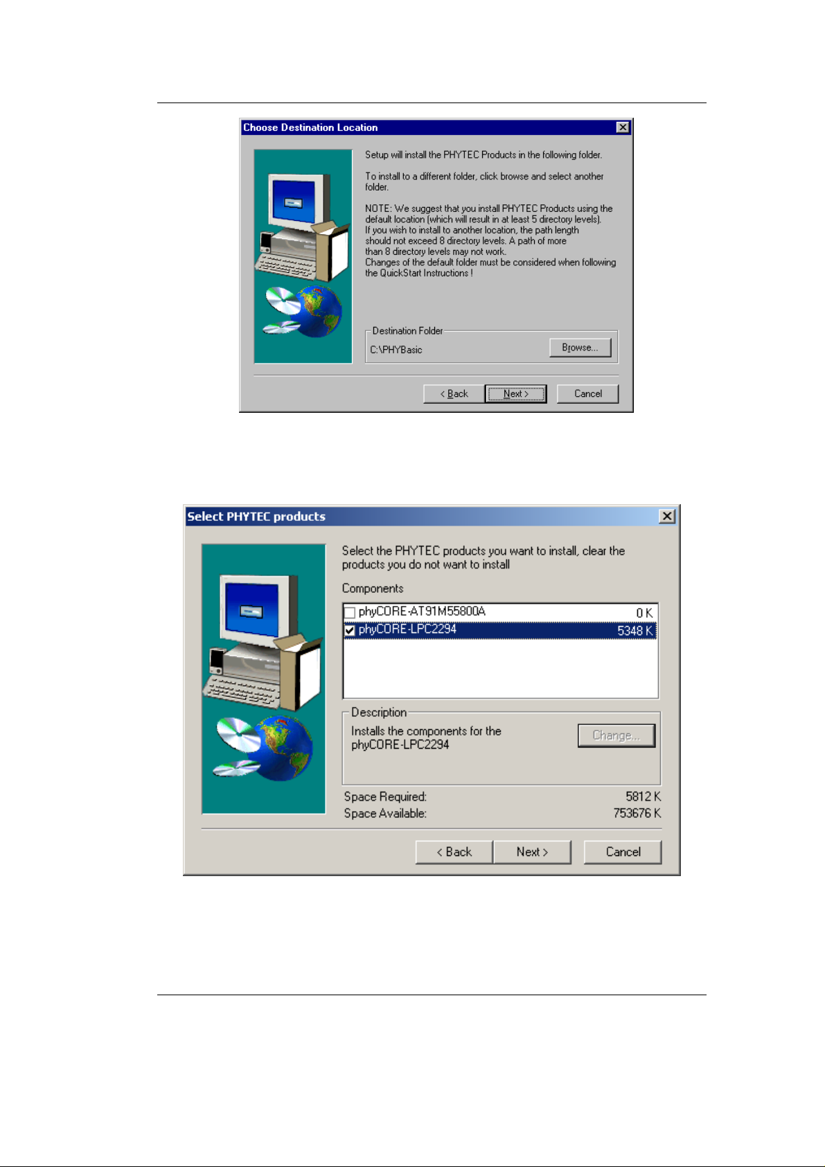
The default destination location is C:\PHYBasic. All path and file
statements within this QuickStart Instruction are based on the
assumption that you accept the default install paths and drives. If you
decide to individually choose different paths and/or drives you must
consider this for all further file and path statements.
We recommend that you accept the default destination location.
10 © PHYTEC Messtechnik GmbH 2005 L-659e_3
Page 15
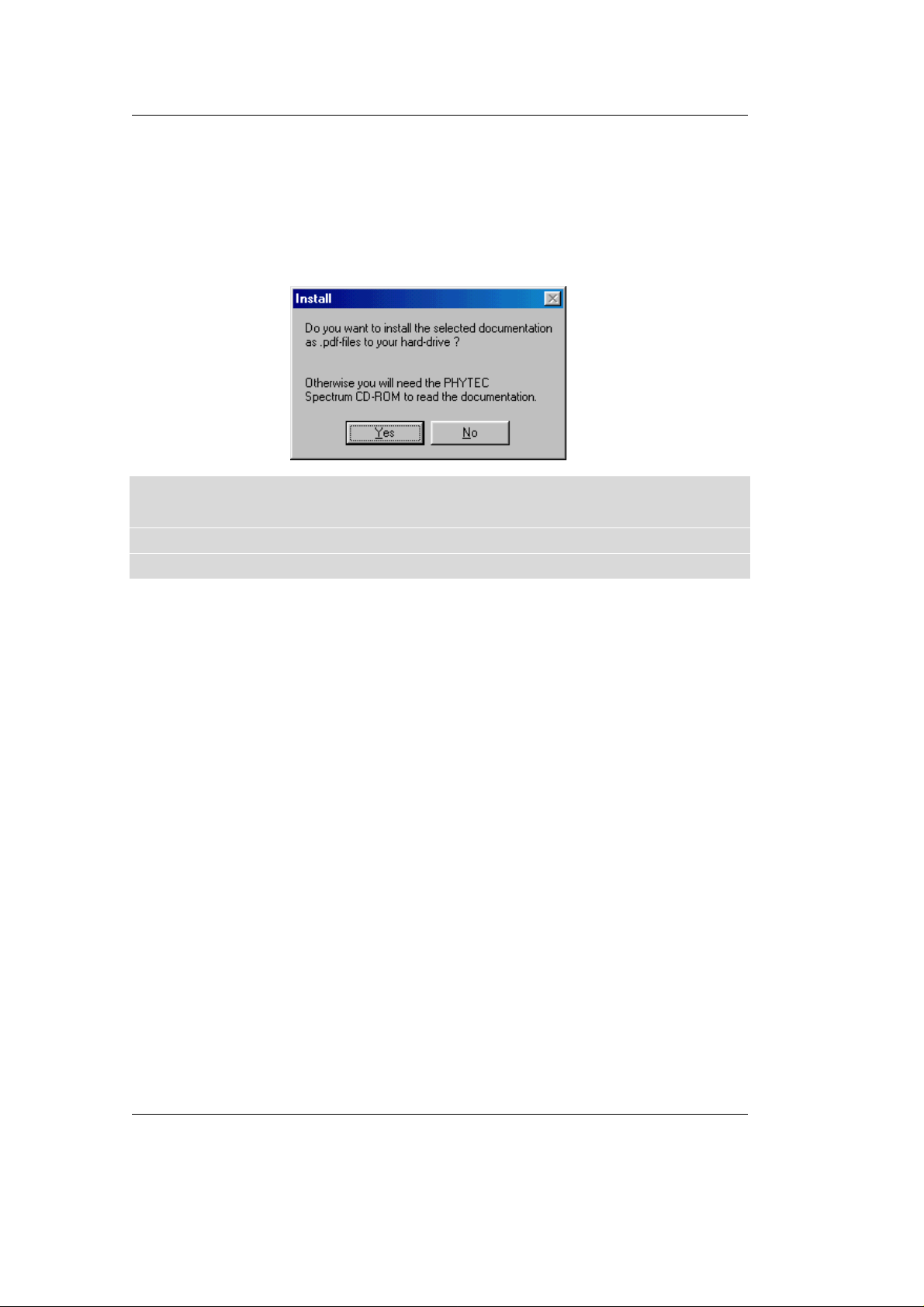
• In the next window select your Rapid Development Kit of choice
from the list of available products.
Getting Started
All Kit-specific content will be installed to a Kit-specific subdirectory
of the Rapid Development Kit root directory that you have specified
at the beginning of the installation process.
© PHYTEC Messtechnik GmbH 2005 L-659e_3 11
Page 16
phyCORE-LPC2294 QuickStart Instructions
All software and tools for this phyCORE-LPC2294 RDK will be
installed to the \PHYBasic directory on your hard-drive.
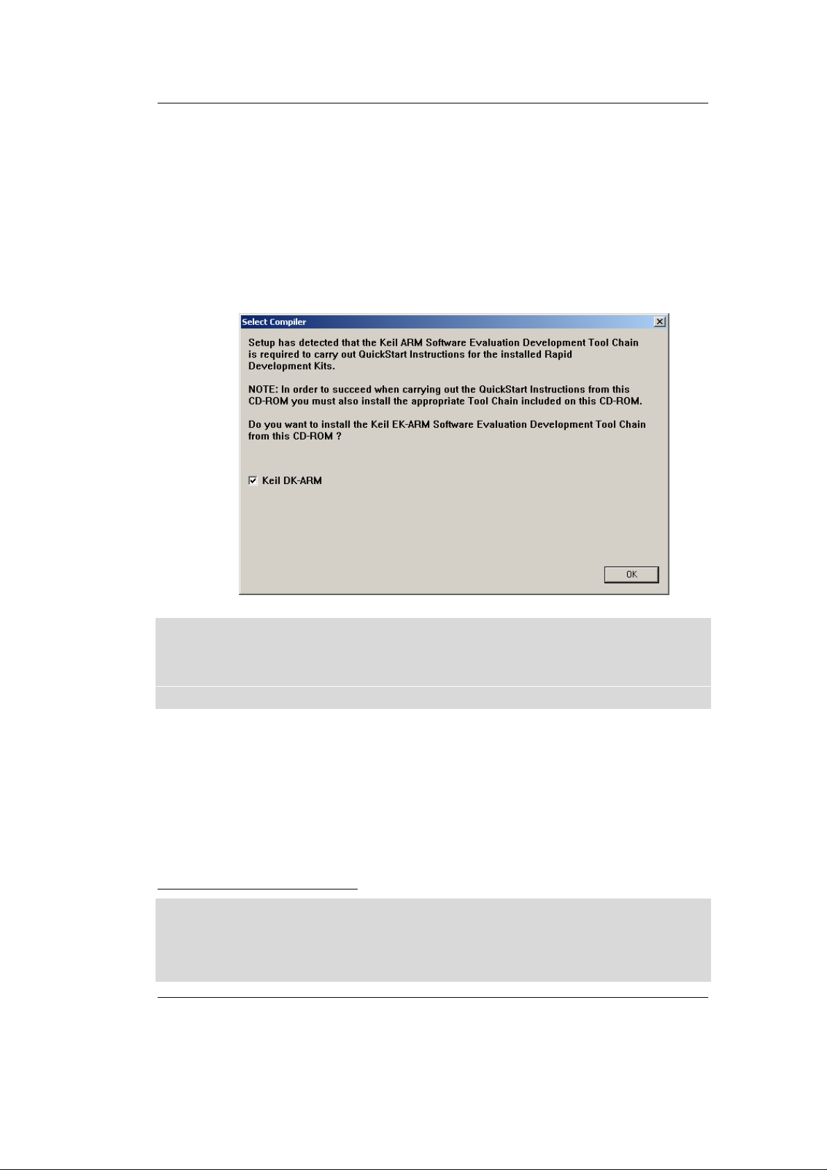
• In the next dialog you must choose whether to copy the selected
documentation as *.pdf files to your hard drive or to install a link
to the file on the Spectrum CD.
If you decide not to copy the documentation to your hard-drive you
will need the PHYTEC Spectrum CD-ROM each time you want to
access these documents. The installed links will refer to your
CD-ROM drive in this case.
12 © PHYTEC Messtechnik GmbH 2005 L-659e_3
Page 17
If you decide to copy the electronic documentation to your hard-drive,
Getting Started
the documentation for this phyCORE
-LPC2294 RDK will also be
installed to the Kit-specific subdirectory.
• Setup will now add program icons to the program folder, named
PHYTEC.
• In the next window, choose the Keil ARM7/µVision3 Software
Development Tool Chain.
The applicable Keil tool chain must be installed to ensure successful
completion of this QuickStart Instruction. Failure to install the proper
software could lead to possible version conflicts, resulting in
functional problems.
We recommend that you install the Keil ARM7 tools and µVision3
from the Spectrum CD-ROM even if other versions of µ Vision3 are
already installed on your system. These QuickStart Instructions and
the demo software included on the CD-ROM have been specifically
tailored for use with one another
1
.
1
: Note: If you have a full version of the Keil ARM7 tools already installed on your host-P C we
recommend installing this evaluation version on a different desktop or laptop computer. If this
is not possible we recommend to use the same version of the Keil ARM7 tools that we use in
this QuickStart manual. PHYTEC can not guarantee successful completion of these
QuickStart instructions if a different version of the Keil ARM7 tools is used.
© PHYTEC Messtechnik GmbH 2005 L-659e_3 13
Page 18
phyCORE-LPC2294 QuickStart Instructions
• After accepting the Welcome window and license agreement select
the destination location for installation of the Development Tool
Chain.
The applicable Keil ARM7/µVision3 evaluation development tool
chain will be installed to your hard-drive.
In the following windows you can decide to install Philips LPC2000
Flash Utility software and the Acrobat Reader. The LPC2000 Flash
Utility must be installed to ensure successful completion of this
QuickStart Instruction. Failure to install the proper software could
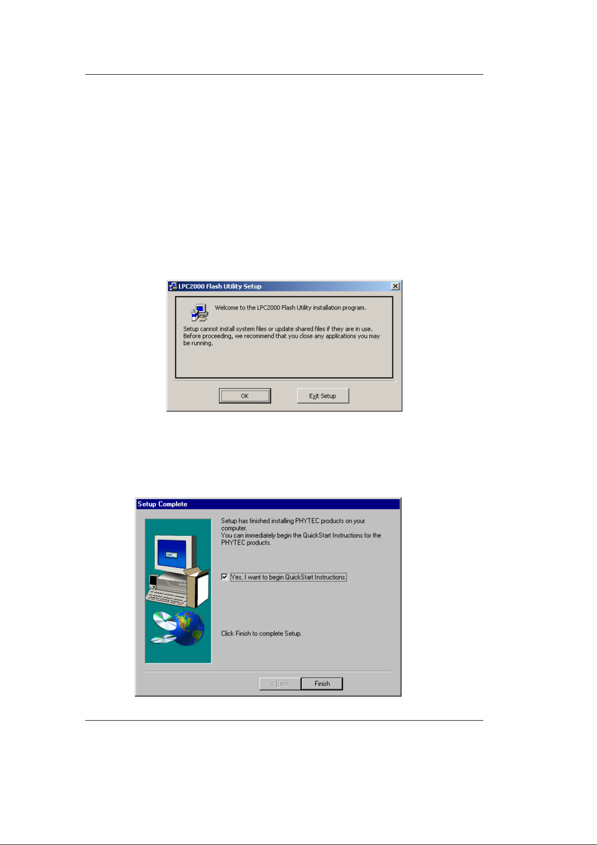
lead to possible version conflicts, resulting in functional problems.
• Click OK and follow the Flash Utility Setup instructions.
• Decide if you want to begin the QuickStart Instruction
immediately by selecting the appropriate checkbox and click on
Finish to complete the installation.
14 © PHYTEC Messtechnik GmbH 2005 L-659e_3
Page 19
2.2 Interfacing the phyCORE-LPC2294 to a Host-PC
Getting Started
Connecting the phyCORE-LPC2294, mounted on the phyCORE
Development Board HD200, to your computer is sim ple.
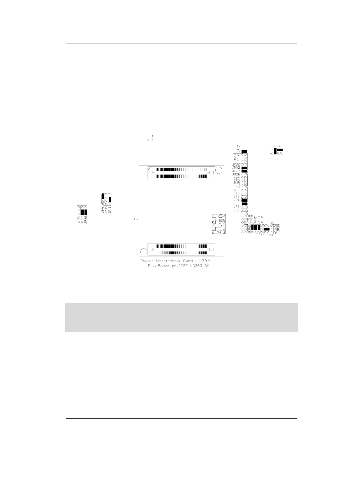
• Ensure proper jumper settings on the phyCORE
Development
Board as shown in Figure 1.
Figure 1: Default Jumper Settings of the phyCORE Development Board
HD200 with phyCORE-LPC2294
Note:
If you do not have a Keil ULINK adapter, skip the following two
bullet points.
• The ULINK JTAG adapter comes with various flat-band cables. In
order to connect this device to the phyCORE
-LPC2294 module
you need to install a flat-band cable with a 2.0 mm connector. If
such a cable is not already installed on your ULINK open the
enclosure and connect the correct 2.0 mm to 2.0 mm cable to the
applicable header connector inside the ULINK. Make sure that
pin #1 on the cable (black wire) matches pin #1 on the connector.
© PHYTEC Messtechnik GmbH 2005 L-659e_3 15
Page 20
phyCORE-LPC2294 QuickStart Instructions
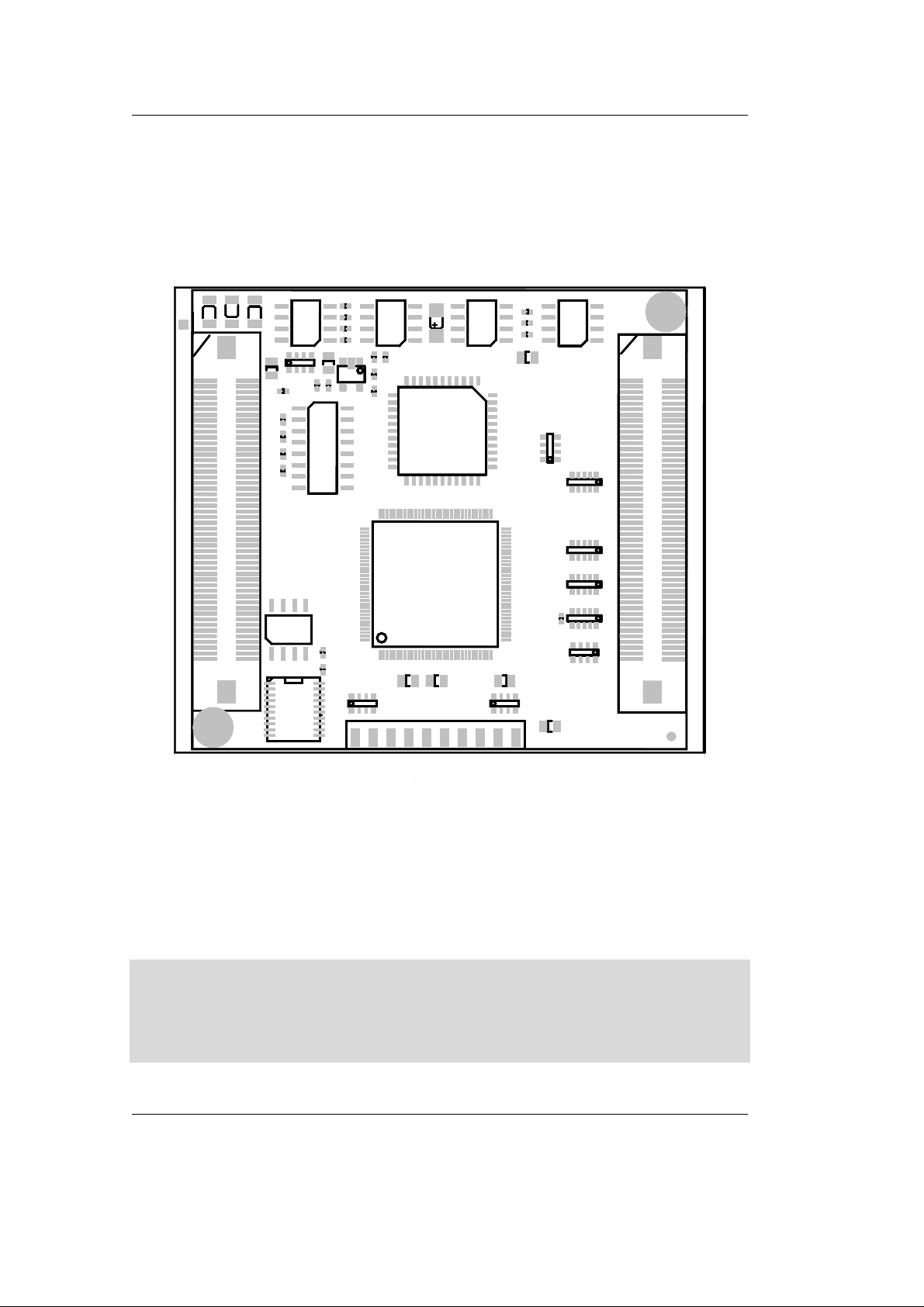
• Connect the other 2.0 mm cable connector onto pin header rows
X701 on the phyCORE
module. Make sure that pin #1 on the
ULINK cable (black wire) is correctly connected to pin #1 on
JTAG connector X701 (located on the connector side of the PCB)
of the phyCORE
-LPC2294 (refer to Figure 2).
19
1
X701
Figure 2: JTAG Connector X701 on the phyCORE-LPC2294 (Bottom View)
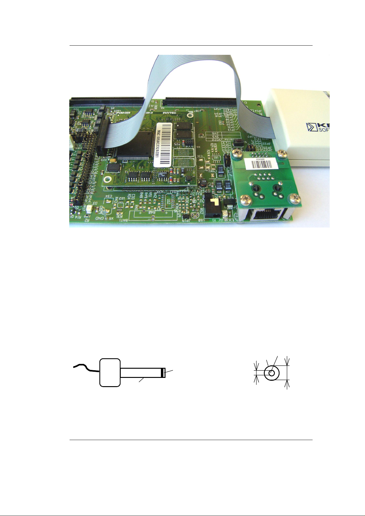
• Mount the phyCORE module, pins-down, onto the Development
Board’s receptacle footprint (X6) as shown in Figure 3 below.
Ensure that pin 1 of the module, designated by the hash stencil
mark, matches pin 1 of the receptacle on the De velopment Board.
Ensure that there is a solid connection between the module’s pins and
the Development Board receptacle. Also take precautions not to
damage the connectors when the phyCORE is removed from and
inserted onto the Development Board.
16 © PHYTEC Messtechnik GmbH 2005 L-659e_3
Page 21
Getting Started
Figure 3: ULINK Connected to the phyCORE Module
• Connect the USB end of the ULINK JTAG adapter to the USB
port of your host-PC using the included USB cable.
• Connect the RS-232 interface of your computer to the DB-9
RS-232 interface on the phyCORE
Development
Board HD200 (P1A = bottom) using the included serial cable.
• Using the included 5V DC power adapter, connect the power
socket X1 on the phyCORE
module to a power supply (refer to
Figure 4 for the correct polarity).
GND
Figure 4: Power Connector
+5 VDC
≥ 500 mA
Polarity:
Center Hole
1.3 mm
-- +
3.5 mm
© PHYTEC Messtechnik GmbH 2005 L-659e_3 17
Page 22

phyCORE-LPC2294 QuickStart Instructions
• The red power LED D2, located next to the power socket at X1,
should light. This indicates that proper voltage is supplied to the
phyCORE
module/Development Board combination (which is
also referred to as "target hardware" within this document).
• The phyCORE
-LPC2294 should now be properly connected to a
host PC via the Development Board and, if available, Keil ULINK .
You are now ready to use the Keil ARM7/µVision3 tools to
establish communication between the host-PC and target
hardware.
2.3 Downloading Example Code with Philips LPC2000 F l ash
Utility
The Philips LPC2000 Flash Utility should have been installed during
the initial setup procedure as described in section 2.1. If not, you can
manually install it using the setup.exe file located in the folder
\Software\Philips\LPC2000 Flash Utility.
Among other tasks, the LPC2000 Flash Utility program downloads
user code in Intel *.hex file format from a host-PC to on-chip Flash
on an LPC229x device populating a PHYTEC SBC via an RS-232
connection.
Note:
Successful completion of this section requires that any user code
residing in external Flash be erased. This is because, upon reset, the
user code in external Flash will execute rather than user code in
internal Flash. For instruction on erasing the external Flash refer to
the instructions for Erasing Flash in section 2.4.1. Typically
PHYTEC Rapid Development Kits are shipped with a blank external
Flash.
18 © PHYTEC Messtechnik GmbH 2005 L-659e_3
Page 23
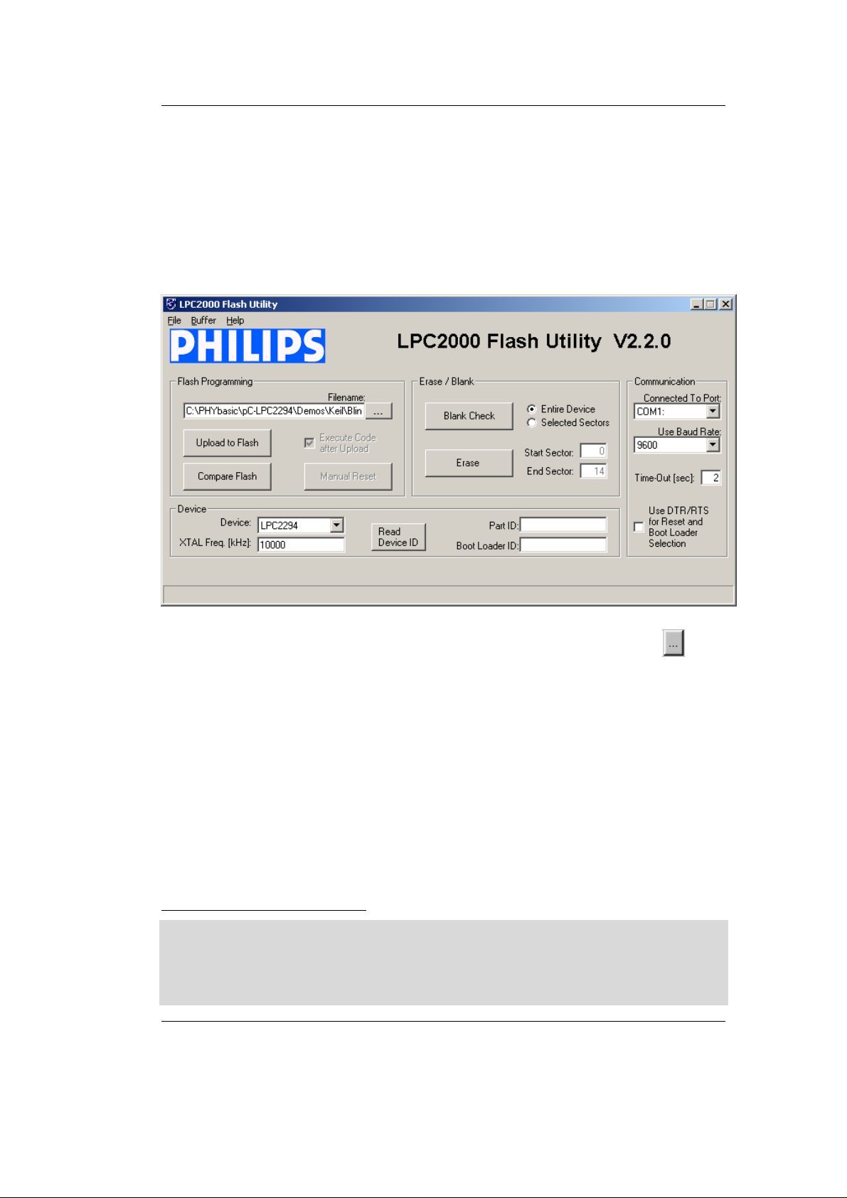
• Start the LPC2000 Flash Utility by selecting it from within the
Programs / LCP2000 Flash Utility program group.
• The LPC2000 Flash Utility GUI will now appear. Here you can
Getting Started
Upload to Flash
1
, compare Flash, erase the Flash, check that the
chip is erased, specify the connection properties, and read the
device ID.
• For Flash programming, click on the browse button and
navigate to the Blinky.hex file to be downloaded within the default
path
C:\PHYBasic\pC-LPC2294\Demos\Keil\Blinky\iFlash\Blinky.hex.
• Be sure the correct Device is selected as LPC2294 and XTAL Freq
is set to 10000 kHz.
• Be sure that the correct Communication Port is set for your
host-PC and select a 9,600 baud rate.
• Click on the Upload to Flash button.
1
: NOTE: PHYTEC typically refers to the process of loading a machine readable file from a
host-PC into a Flash device populating a PHYTEC Single Board Computer as "download". In
this section we will use the term "Upload to Flash" as defined within the Philips LPC2000
Flash Utility for reasons of being consistent with their terminology. In all other sections of
this manual we will use the term "Flash download".
© PHYTEC Messtechnik GmbH 2005 L-659e_3 19
Page 24

phyCORE-LPC2294 QuickStart Instructions
• The following window will appear:
• Put the target hardware in Bootloader mode by simultaneously
pressing the Boot (S_1) and Reset (S_2) buttons on the
Development Board, first release the Reset button and, about
3 seconds later, the Boot button.
• Now click on OK.
• You will see the file upload progress in the lower bar of the
LPC2000 Flash Utility window. When successful the bar will
indicate File Upload Successfully Completed.
• Upon completion of file upload to on-chip Flash, press the Reset
button S_2 on the Development Board.
• Successful download of the blinky demo will result in the LED D3
on the Development Board blinking on and off at equal intervals.
20 © PHYTEC Messtechnik GmbH 2005 L-659e_3
Page 25

2.4 Downloading Example Code with µVision3
The µVision3 evaluation software development tool chain should
have been installed during the install of the PHYTEC Rapid
Development Kit Software from the Spectrum CD, as described in
section 2.1.
You can also manually install the ARM7/µVision3 tools by executing
KARM220.EXE from within the \Software\Keil\Arm directory of
your PHYTEC Spectrum CD. Follow the instructions displayed by the
setup program for manual installation.
Note:
It is recommended to use the Keil tool chain provided on the
accompanying Spectrum CD in order to complete this QuickStart
Instruction successfully. Use of a different version could lead to
possible version conflicts, resulting in functional problems1.
Getting Started
Start the tool chain by selecting Keil µVision3 from within the
µ
programs group: Start\Programs\Keil
Vision3 or by double-clicking
on the Keil µVision3 icon on your desktop.
1
: Note: If you have a full version of the Keil ARM7 tools already installed on your host-PC we
recommend installing this evaluation version on a different desktop or laptop computer. If this
is not possible we recommend to use the same version of the Keil DK-ARM tools that we use
in this QuickStart manual. PHYTEC can not guarantee successful completion of these
QuickStart instructions if a different version of the Keil DK-ARM tools is used.
© PHYTEC Messtechnik GmbH 2005 L-659e_3 21
Page 26
phyCORE-LPC2294 QuickStart Instructions
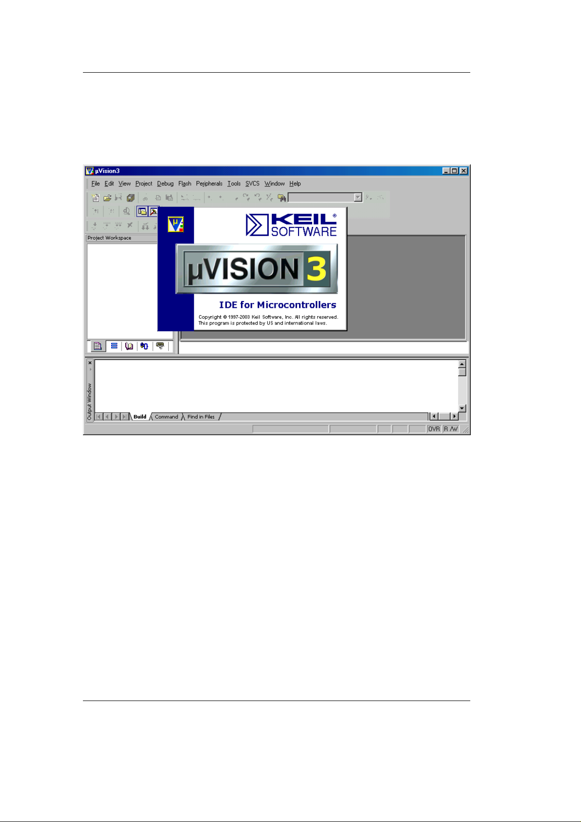
After you start µVision3, the window shown below appears. From
this window you can create projects, edit files, configure tools,
assemble, link and start the debugger. Close all projects that might be
open by selecting Project / Close Project.
2.4.1 "Blinky"
The "Blinky" example downloads a program to external Flash that,
when executed, manipulates the LED D3 on the phyCORE
Development Board HD200.
• Open the Blinky project from the µVision3 menu Project / Open
Project.
• Browse to C:\PHYBasic\pC- LPC2294\Demos\Keil\Blinky.
22 © PHYTEC Messtechnik GmbH 2005 L-659e_3
Page 27
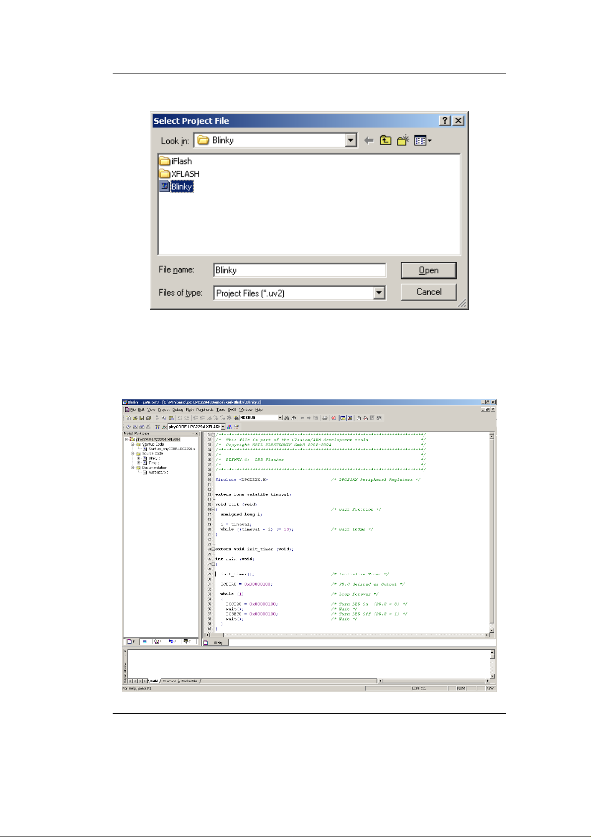
• Select the Blinky project.
• Click Open.
Getting Started
• In the Select Target pull-down menu be sure that the
phyCORE-LPC2294 XFLASH target is selected.
© PHYTEC Messtechnik GmbH 2005 L-659e_3 23
Page 28
phyCORE-LPC2294 QuickStart Instructions
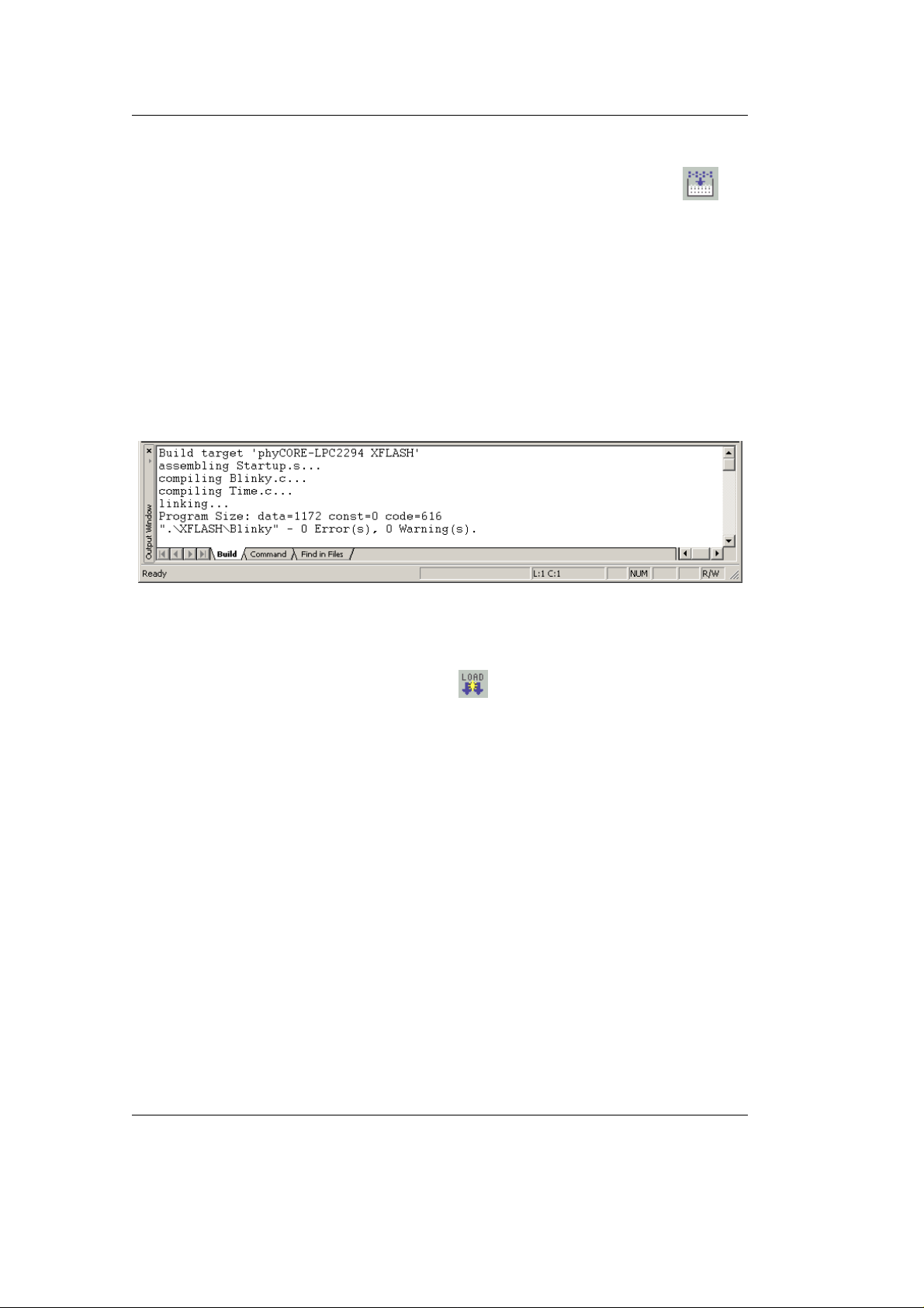
Build the Project
• Build the target by either selecting the Build Target icon on
the build toolbar or in the main menu bar select Project / Build
target.
• If any source file of the project contains any errors, they will be
shown in the Output Window - Build tab. Use the editor to
correct the error(s) in the source code, save the file and repeat the
build.
• If there are no errors, the code is ready to be downloaded into the
external Flash memory.
Download to Flash
• Download the code into Flash memory by either selecting the
Download to Flash Memory icon
on the build toolbar or in the
main menu bar select Flash / Download.
• The individual steps of the Flash download procedure can be
viewed at the bottom of the µVision3 Output Window - Build
tab.
• Wait until the programming is complete. This is indicated by the
"Verify OK" message. The download utility will perform a reset
and the code will execute without further user interaction.
Successful execution of the program will flash the LED D3 with equal
on and off duration.
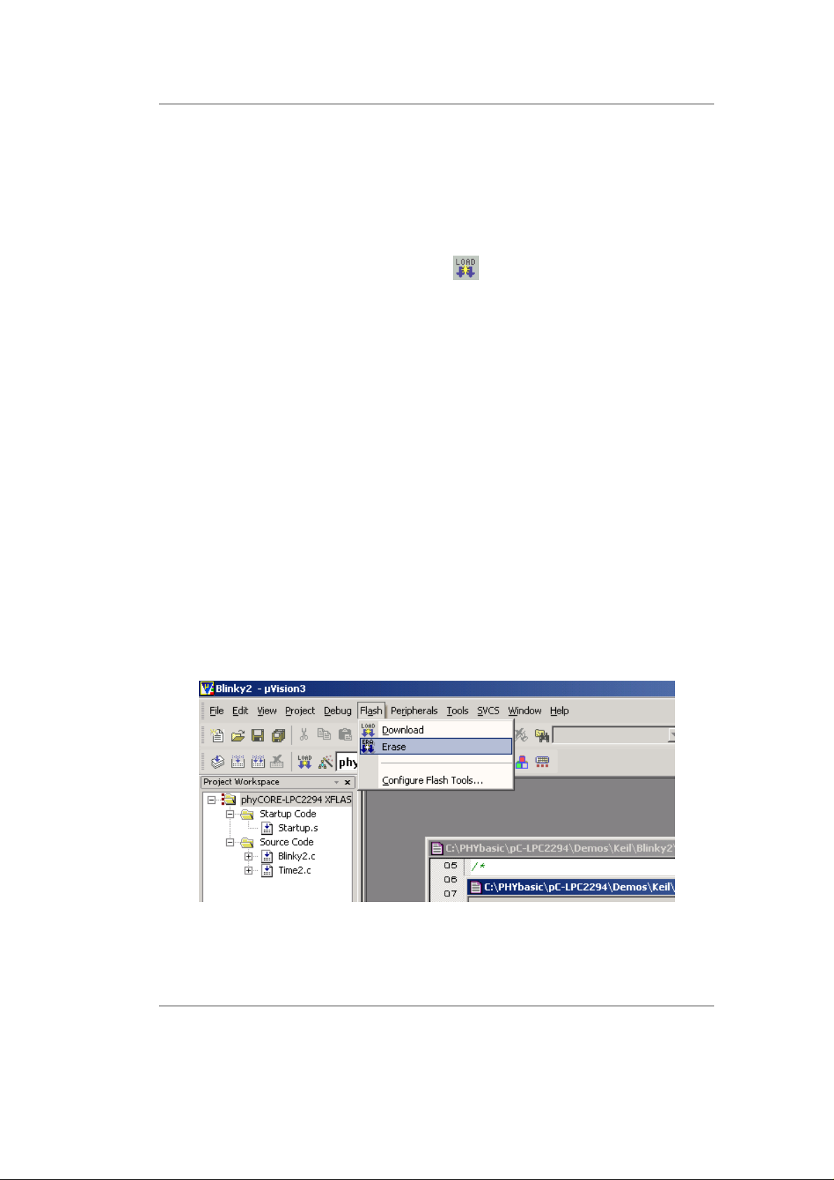
Erase Flash
• To erase Flash, select Flash/Erase from the uVision toolbar. This
requires that a project with an XFLASH target is open.
24 © PHYTEC Messtechnik GmbH 2005 L-659e_3
Page 29
2.4.2 "Hello"
The "Hello" example downloads a program to the external Flash that,
when executed, sends a character string from the target hardware back
to the host-PC. The character string can be viewed with a terminal
emulation program. This example program provides a review of the
Flash download procedure using the Keil ULINK and µVision3.
Monitoring the execution of the Hello demo requires use of a terminal
program, such as the HyperTerminal program included within
Windows.
• Start the HyperTerminal program within the Programs
/Accessories/Communications bar.
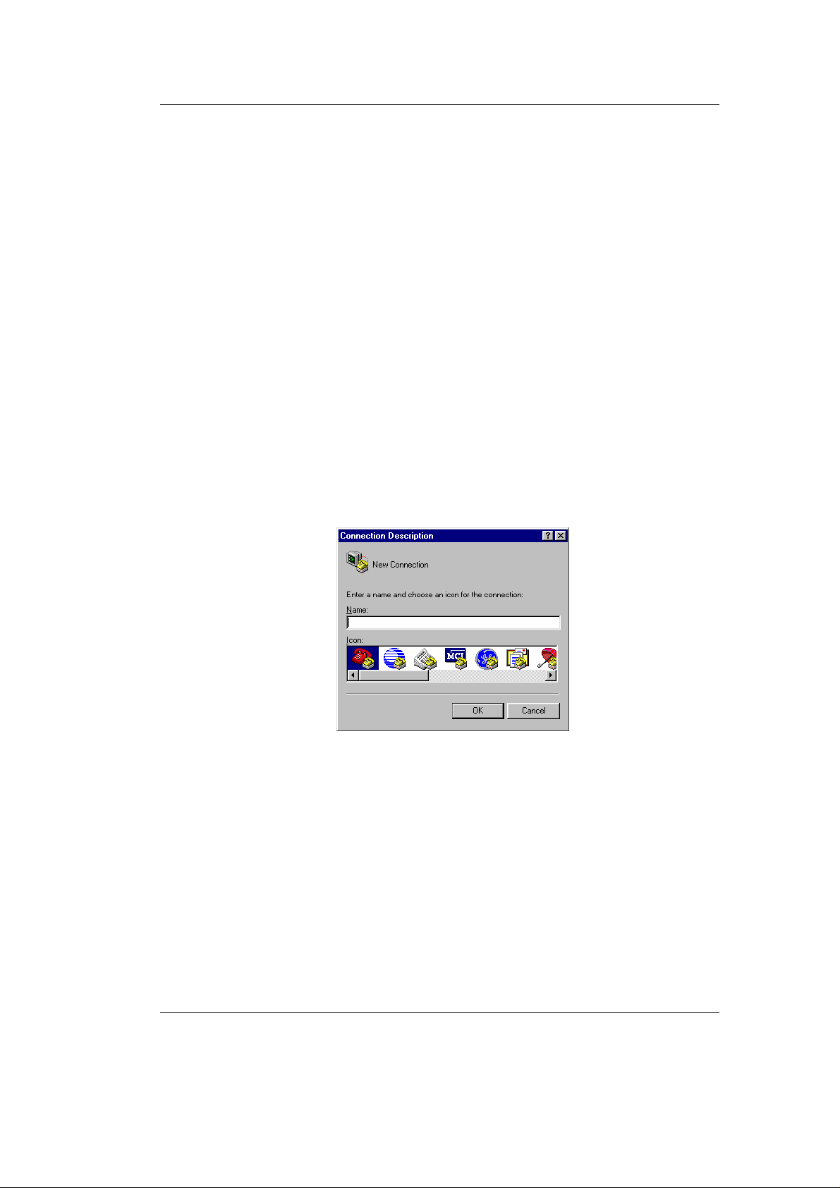
• The Connection Description window will now appear. Enter
"COM Direct" in the Name text field.
Getting Started
© PHYTEC Messtechnik GmbH 2005 L-659e_3 25
Page 30
phyCORE-LPC2294 QuickStart Instructions
• Next click on OK. This creates a new HyperTerminal session
named "COM Direct" and advances you to the next
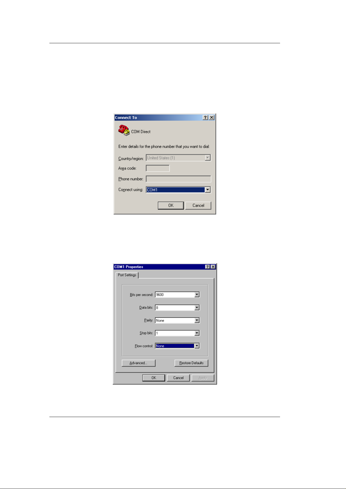
HyperTerminal window. Specify COM1 under the Connect Using
pull-down menu (be sure to indicate the correct COM setting for
your system).
• Click OK to advance to the next window (COM1 Properties).
• Then set the following COM parameters: Bits per second = 9,600;
Data bits = 8; Parity = None; Stop Bits = 1; Flow Control = None.
26 © PHYTEC Messtechnik GmbH 2005 L-659e_3
Page 31
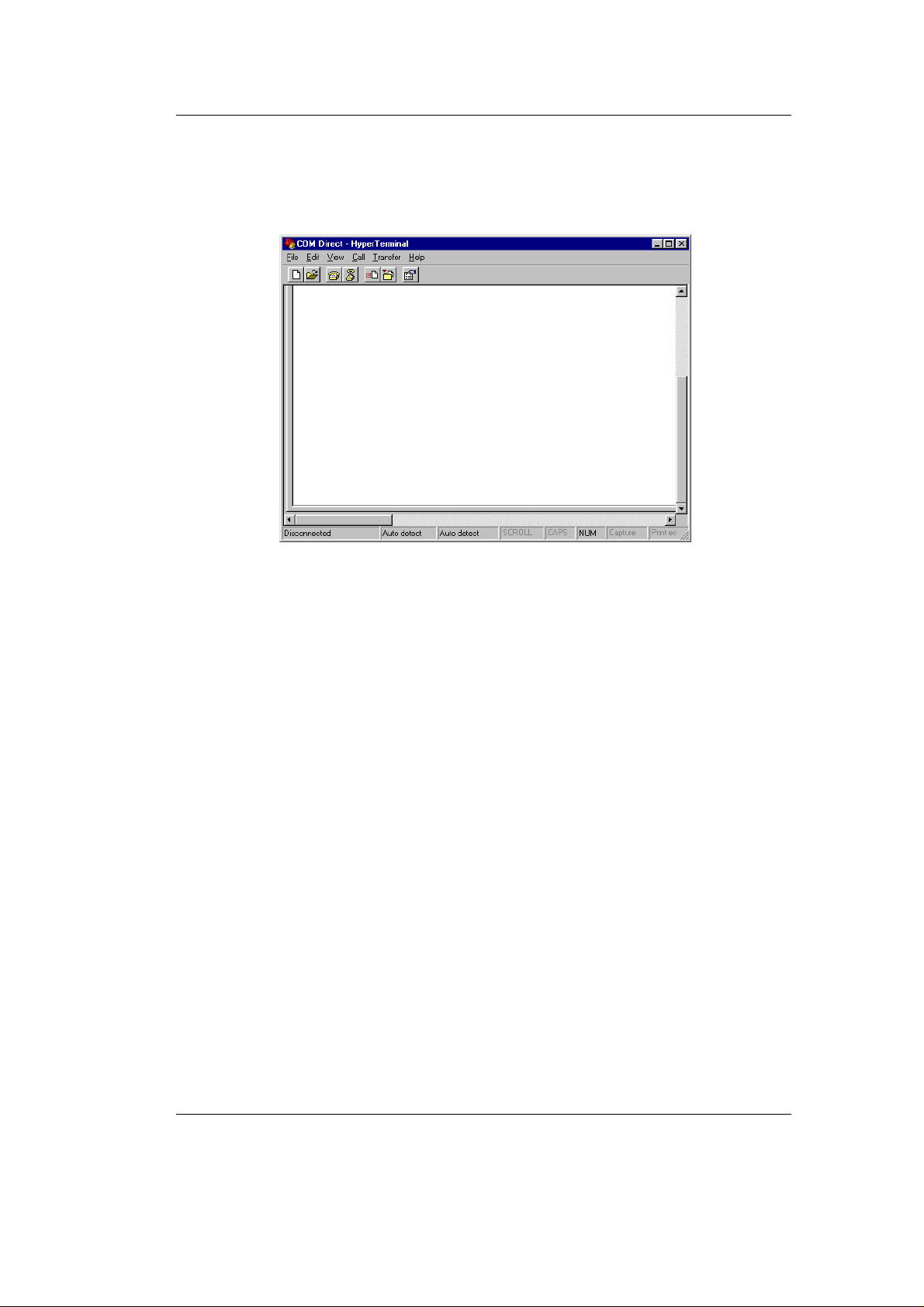
• Selecting OK advances you to the COM Direct–HyperTerminal
monitoring window. Notice the connection status report in the
lower left corner of the window.
Getting Started
• Ensure that the target hardware is properly connected to the
host-PC via the ULINK and serial cable as well as a power supply.
© PHYTEC Messtechnik GmbH 2005 L-659e_3 27
Page 32
phyCORE-LPC2294 QuickStart Instructions
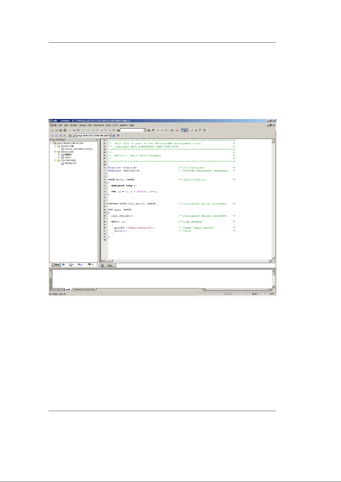
• Open the Hello project from the µVision3 menu Project / Open
Project.
• Browse to the correct drive and path for the phyCORE
demo folder (default location
C:\PHYBasic\pC-LPC2294\Demos\Keil\Hello\)
and click Open.
-LPC2294
• In the Select Target pull down menu be sure that the
phyCORE-LPC2294 XFLASH target is selected.
28 © PHYTEC Messtechnik GmbH 2005 L-659e_3
Page 33

Build the Project
Getting Started
• Click on the Build Target icon
on the build toolbar to build
the target.
• If any source file of the project contains any errors, they will be
shown in the Output Window - Build tab. Use the editor to
correct the error(s) in the source code, save the file and repeat the
build.
• If there are no erorrs, the code is ready to be downloaded into the
Flash memory.
Download to Flash
• Click on the Download to Flash Memory icon
in the build
toolbar to download the code into Flash memory.
• Wait until the programming is complete. This is indicated by the
"Verify OK" message. The download utility will perform a reset
and the code will execute without further user interaction.
• Successful program execution will send the character string "Hello
World" from the target hardware to the HyperTerminal window.
• If no output appears in the HyperTerminal window check the
power supply, the COM parameters and the RS-232 connection.
The code within the demo application Hello initializes the serial port
of your phyCORE-LPC2294 to 9600 baud. The initialization values
are based on the assumption that the microcontroller runs at a 60 MHz
internal clock frequency. If your phyCORE-LPC2294 is equipped
with a different speed oscillator, the demo application might transmit
using another baud rate. This may lead to incoherent characters
appearing in the HyperTerminal window following execution of code.
• Click the disconnect icon in HyperTerminal toolbar and exit
HyperTerminal.
© PHYTEC Messtechnik GmbH 2005 L-659e_3 29
Page 34

phyCORE-LPC2294 QuickStart Instructions
30 © PHYTEC Messtechnik GmbH 2005 L-659e_3
Page 35
3 Getting More Involved
What you will learn with this example:
• how to configure the µVision3 IDE (Integrated Development
Environment)
• how to modify the source code from our examples, create a new
project and build and download a machine-readable output file to
the target hardware
3.1 Creating a New Project and Adding an Existing Source
File
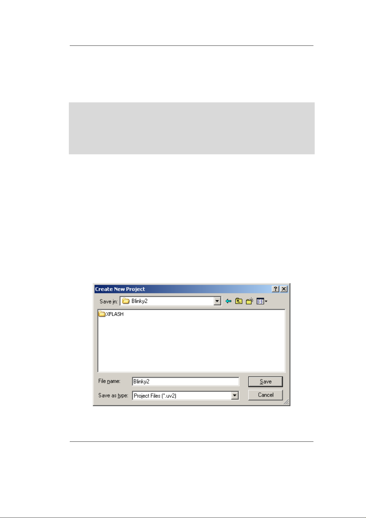
• To create a new project file select from the µVision3 menu
Project|New Project…. This opens a standard Windows dialog
that asks you for the new project file name.
Getting More Involved
• Change to the project directory created by the installation
procedure (default location
C:\PHYBasic\pC-LPC2294\Demos\Keil\Blinky2).
• In the text field ’File name’, enter the file name of the project as
Blinky2.uv2 and click on Save.
© PHYTEC Messtechnik GmbH 2005 L-659e_3 31
Page 36
phyCORE-LPC2294 QuickStart Instructions
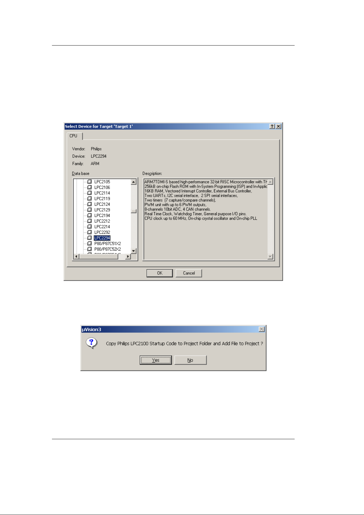
• The Select Device for Target ’Target1’ window will automatically
appear. Select Philips as manufacturer for the CPU. The
phyCORE
-LPC2294 is populated with an LPC2294 CPU.
Choose the controller type from the list as shown below. This
selection sets necessary tool options for the LPC2294 device and
simplifies in this way the project configuration.
• Click on OK to save the settings.
• The uVision3 dialog box "Copy Philips LPC2100 Startup Code to
Project Folder and Add File to Project?" will appear.
• Click on No to not include this default startup code! The default
startup code provided by Keil does not match the
phyCORE-LPC2294 hardware properties. The correct startup file
called startup_phyCORE-LPC2294.s will be added to the project
later.
32 © PHYTEC Messtechnik GmbH 2005 L-659e_3
Page 37
3.1.1 Configure the Project Components
Getting More Involved
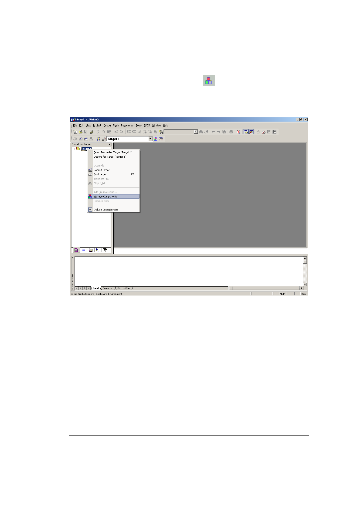
• To configure the target click on the
icon in the build toolbar or
right-click on the target, ’Target 1’ in the Project Workspace
window and select Manage Components.
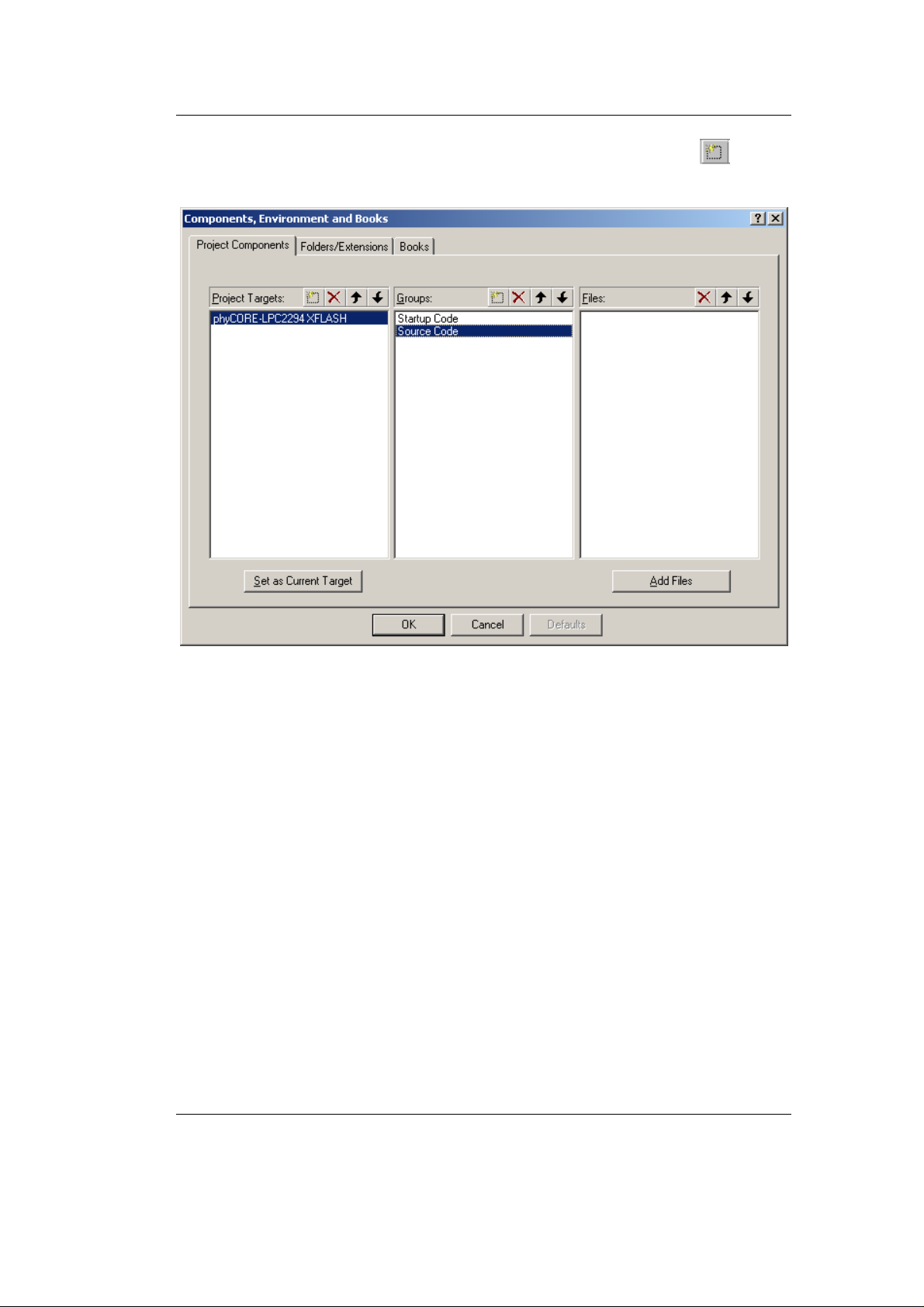
• The Components, Environments, and Books window will
appear.
© PHYTEC Messtechnik GmbH 2005 L-659e_3 33
Page 38
phyCORE-LPC2294 QuickStart Instructions
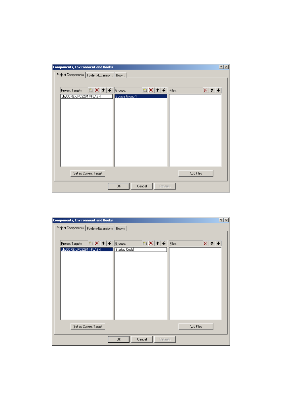
• In the Project Components tab, double-click on Target 1. Change
the name of the target to phyCORE-LPC2294 XFLASH.
• Double-click on Source Group 1, in the Groups window, and
change the name of the group to Startup Code.
34 © PHYTEC Messtechnik GmbH 2005 L-659e_3
Page 39
Getting More Involved
• Add another group by selecting the New(Insert) icon
Groups window. Nam e the new group Source Code.
in the
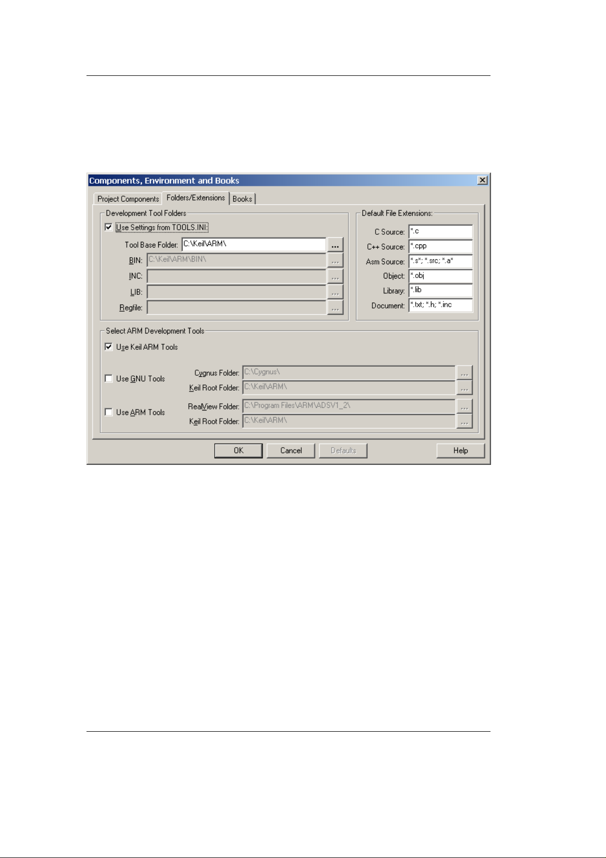
• Select the Folders/Extensions tab.
© PHYTEC Messtechnik GmbH 2005 L-659e_3 35
Page 40
phyCORE-LPC2294 QuickStart Instructions
• Be sure that Use Settings from TOOLS.INI is checked and the path
for the Tool Based Folder is C:\Keil\ARM\
• Be sure that Use Keil ARM Tools ARM Development Tools is
selected.
• Click OK. This brings you back to the Project Workspace
window.
• You are now ready to add source files to the project. Make sure the
view in the Project Workspace window is expanded to see both
file groups.
36 © PHYTEC Messtechnik GmbH 2005 L-659e_3
Page 41
3.1.2 Adding Source Files to the Project
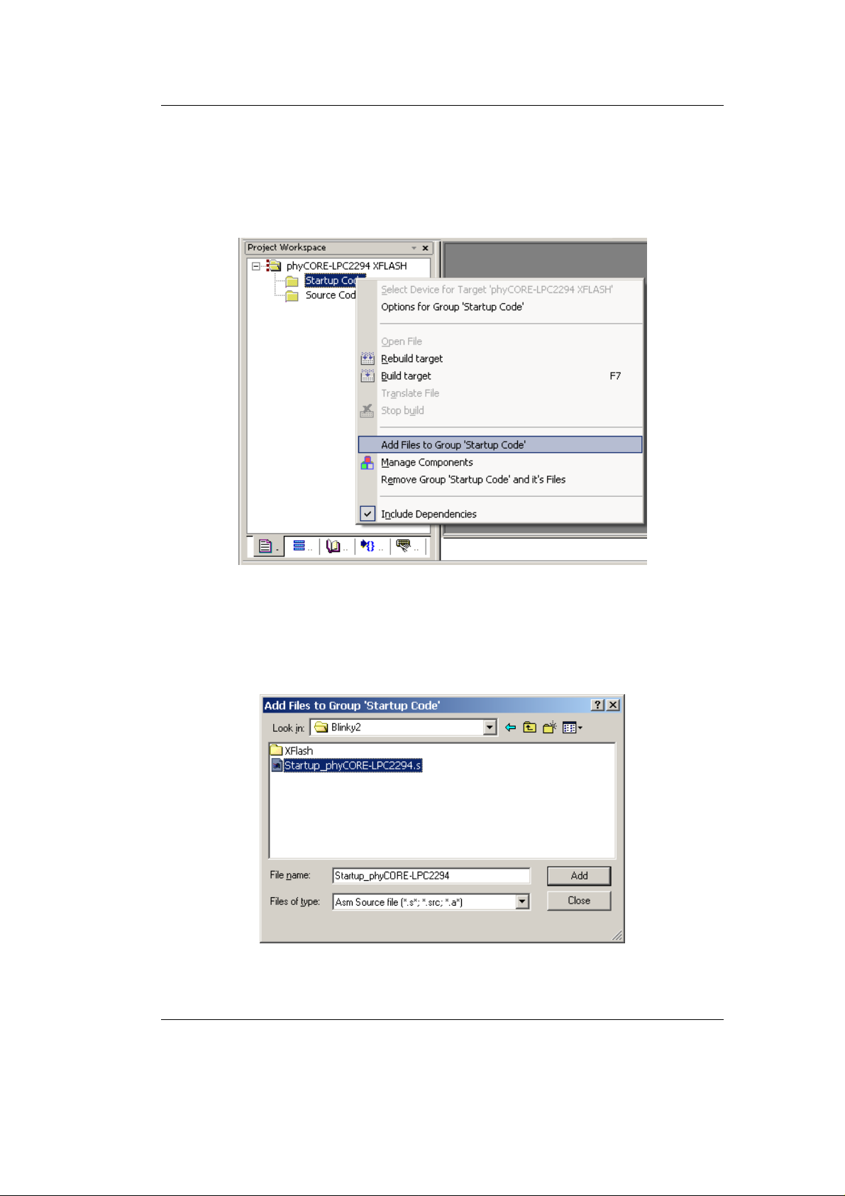
• In the Project Workspace window - Files tab right-click on
Startup Code and select Add Files to Group ‘Startup Code’.
Getting More Involved
• In the File of type pull-down menu, select: "Asm Source file (*.s*;
*.src*; .a*)". Browse to
C:\PHYBasic\pC-LPC2294\Demos\Keil\Blinky2
and select Startup_phyCORE-LPC2294.s .
• Click on the Add button and then click Close.
© PHYTEC Messtechnik GmbH 2005 L-659e_3 37
Page 42
phyCORE-LPC2294 QuickStart Instructions
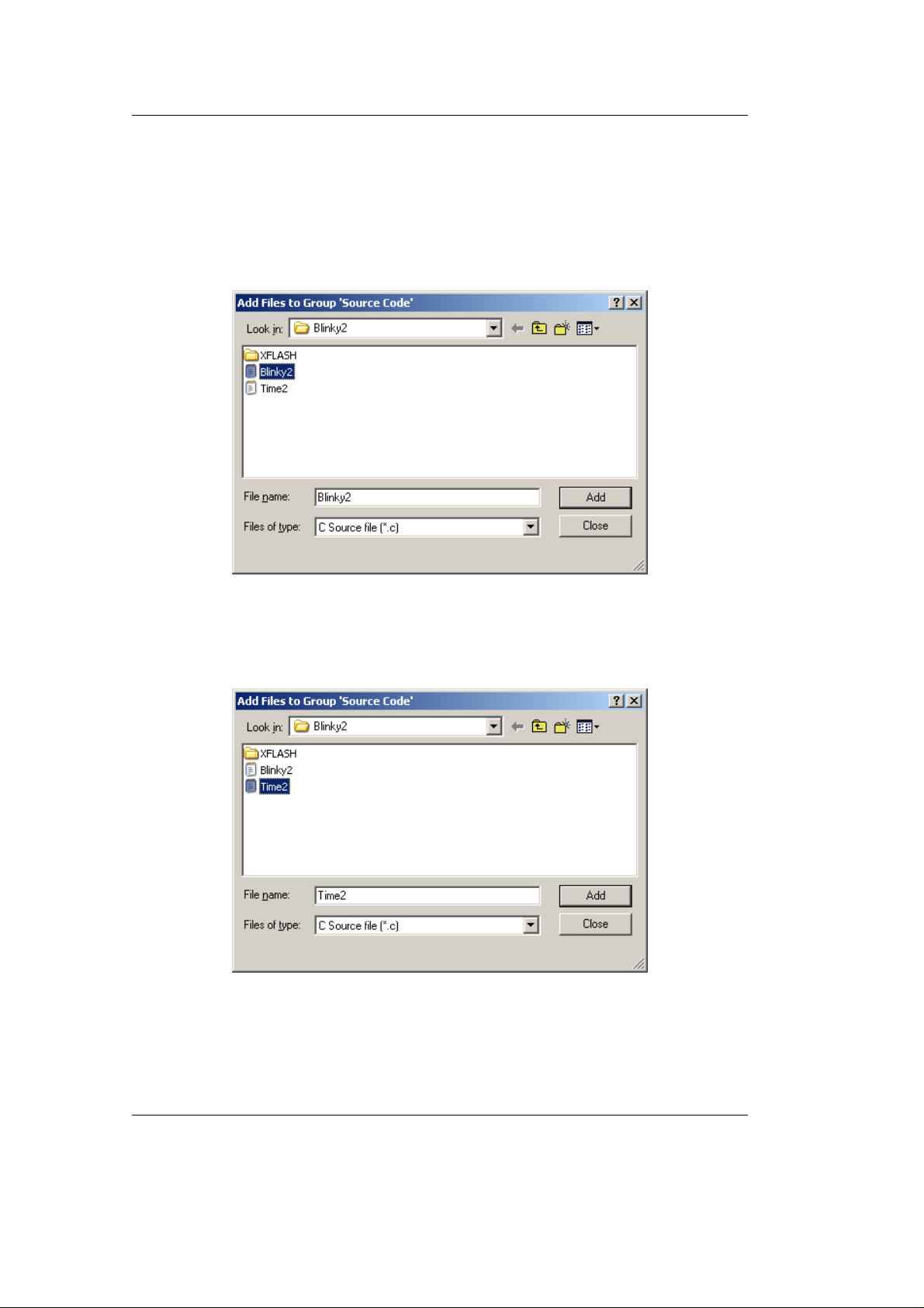
• In the Project Workspace window right-click on the Source Code
group.
• Select Add Files to Group ’Source Code’.
• Browse to C:\PHYBasic\pC-LPC2294\Demos\Keil\Blinky2 and
select Blinky2.c.
• Click on the Add button.
• Select Time2.c.
• Click on the Add button and then click Close.
38 © PHYTEC Messtechnik GmbH 2005 L-659e_3
Page 43
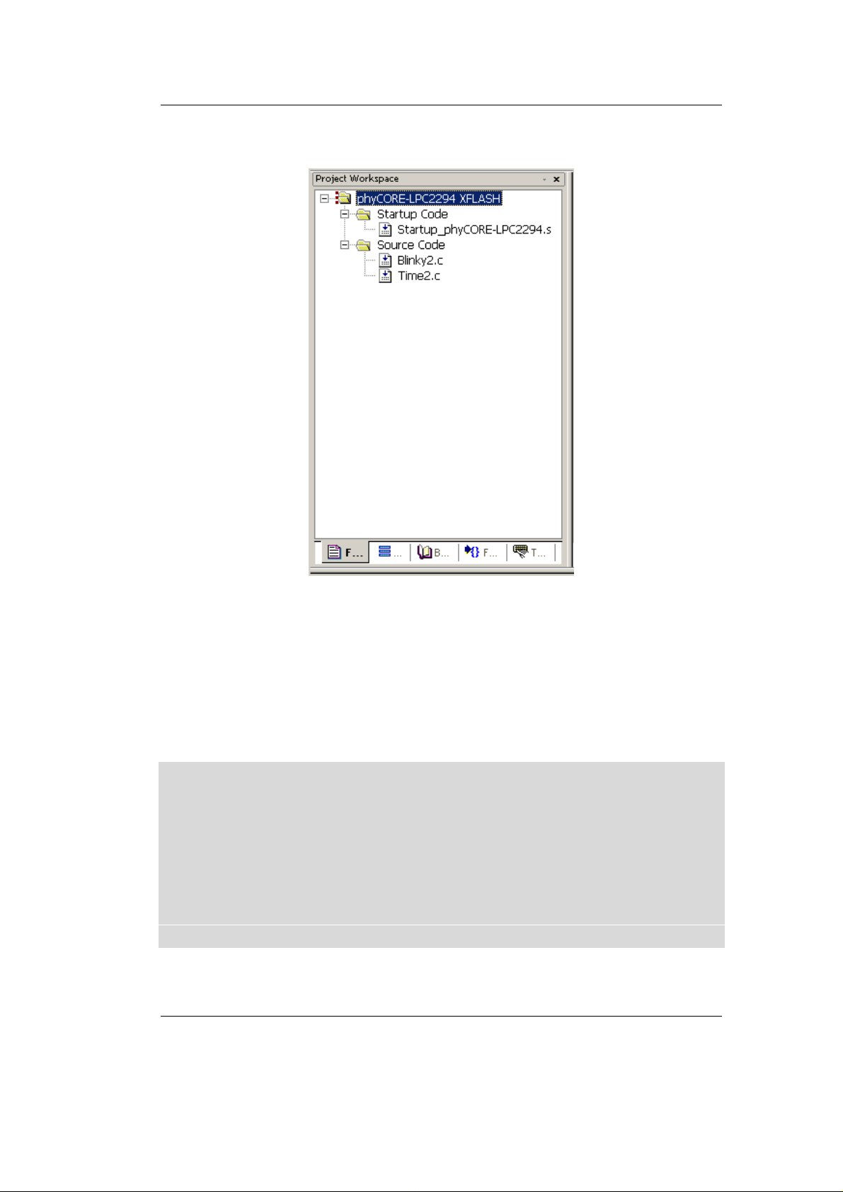
• The Project Workspace window should appear as follows:
Getting More Involved
At this point you have created a project called Blinky2.uv2 and added
an existing C source file called Blinky2.c and Time2.c and an existing
assembly source file called Startup_phyCORE-LPC2294.s. The next
step is to modify the C source file before building your project. This
includes compiling, linking, locating and creating the machinereadable file.
NOTE:
Always use the Startup_phyCORE-LPC2294.s file provided by
PHYTEC in your application project. This startup file contains the
correct controller setting for access to external memory and other
on-board components. Using other startup code, e.g. the default Keil
startup code that is offered when creating a new project will lead to
functional problems and may cause your application code to not
execute as desired.
© PHYTEC Messtechnik GmbH 2005 L-659e_3 39
Page 44
phyCORE-LPC2294 QuickStart Instructions
3.2 Modifying the Source Code
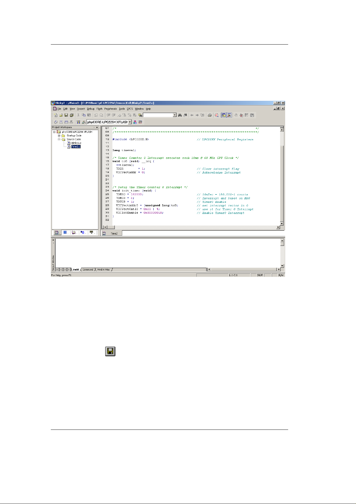
• Double-click on Time2.c in the Project Workspace window to
open the file in the source code editor.
• Locate the following code section and modify the delay for LED
flashes from the original 149999 to 549999.
T0MR0 = 149999; // 10mSec = 150.000-1 counts
• Save the modified file by choosing File / Save or by clicking the
floppy disk icon .
40 © PHYTEC Messtechnik GmbH 2005 L-659e_3
Page 45

3.3 Setting Options for Flash Target
Keil includes a Make utility that can control compiling and linking
source files in several programming languages. Before building your
project you must configure the target options. Most of the options are
set when specifying the target device for the project.
Enter the changes as indicated below and leave all other options set to
their default values. µVision3 allows you to set various options with
mouse clicks and these are all saved in your project *.opt file.
• Configure options for target by selecting the Options for Target
Getting More Involved
icon
on the build toolbar or right-click on the
phyCORE-LPC2294 XFLASH target in the Project Workspace
window and select Options for Target ‘phyCORE-LPC2294
XFLASH’.
© PHYTEC Messtechnik GmbH 2005 L-659e_3 41
Page 46
phyCORE-LPC2294 QuickStart Instructions
Configure the Target Options
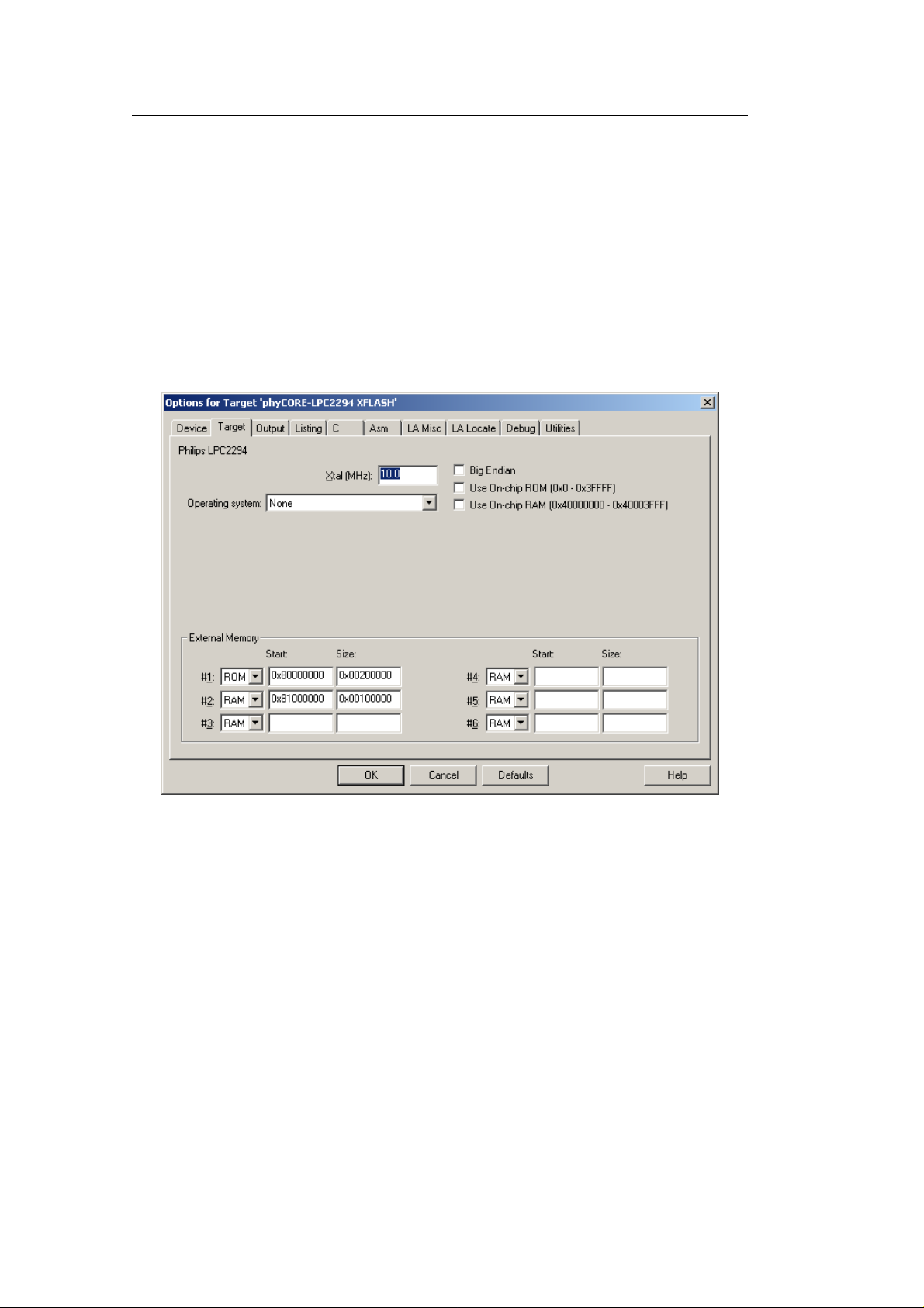
• In the Target tab be sure that the Xtal is set to 10 MHz and Use
On-chip ROM(0x0-0x3FFFF) as well as Use On-chip
RAM(0x40000000-0x40003FFF) are not checked. Set the External
Memory #1 to ROM and #2 to RAM and set the Start and Size as
follows:
ROM: 0x8000 0000 (Start) 0x0020 0000 (Size)
RAM: 0x8100 0000 (Start) 0x0010 0000 (Size)
It is necessary to configure the External Memory Start and Size
settings so that the user code and data does not exceed the physical
size of the memory. The phyCORE
-LPC2294 standard version
features 2 MByte of external Flash and 1 MByte of external SRAM.
42 © PHYTEC Messtechnik GmbH 2005 L-659e_3
Page 47
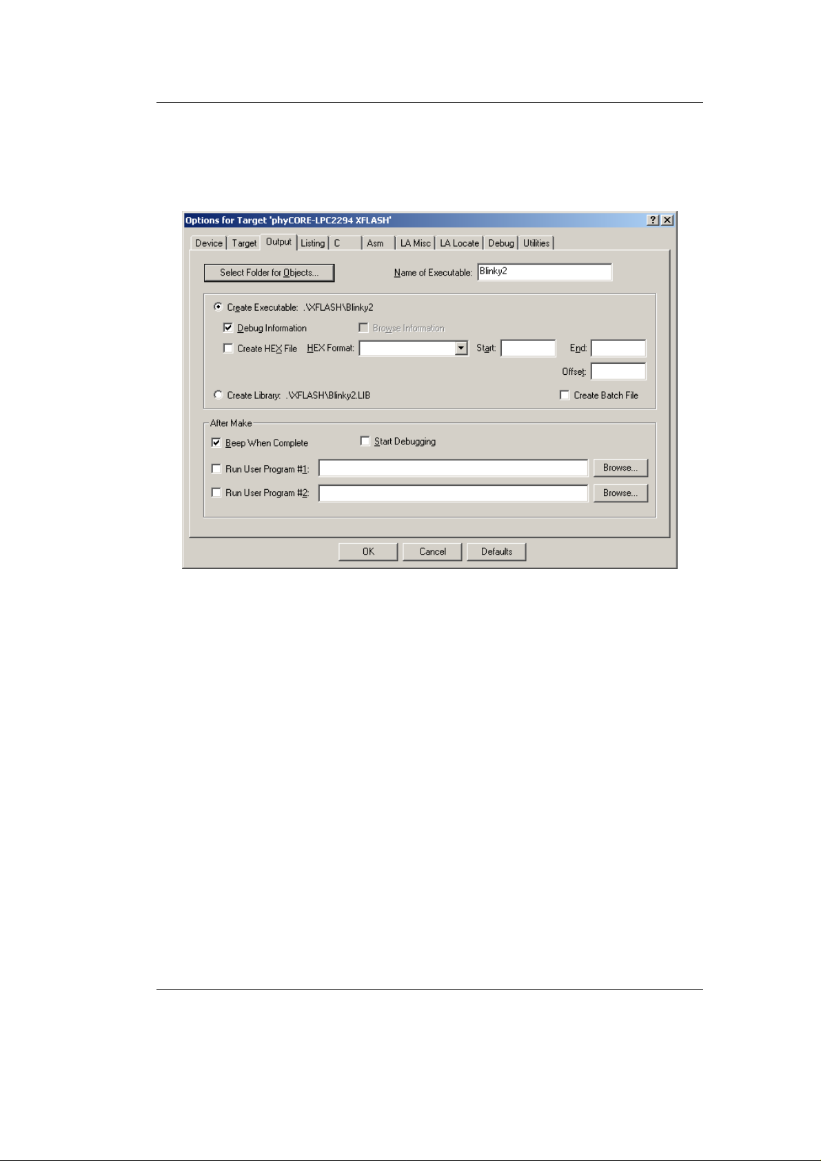
Configure the Output Options
• In the Output tab be sure that Create Executable, Debug
Information and Beep When Complete options are selected.
Getting More Involved
• Click on the Select Folder for Objects button.
© PHYTEC Messtechnik GmbH 2005 L-659e_3 43
Page 48
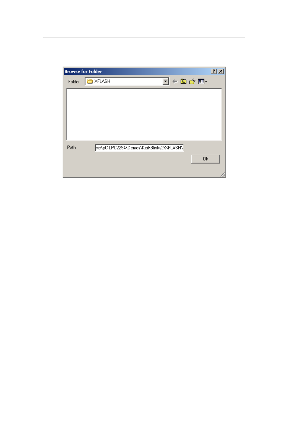
phyCORE-LPC2294 QuickStart Instructions
• Browse to the folder:
C:\PHYBasic\pC-LPC2294\Demos\Keil\Blinky2\XFLASH.
• Click Ok. This takes you back to the Options for Target window.
44 © PHYTEC Messtechnik GmbH 2005 L-659e_3
Page 49
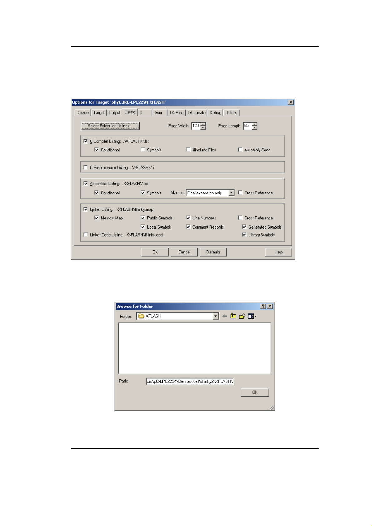
Configure the Listing Options
• In the Listing tab, be sure that the default settings are set as
follows.
Getting More Involved
• Click on the Select Folder for Listings button.
• Browse to the folder:
C:\PHYBasic\pC- LPC2294\Demos\Keil\Blinky2\XFLASH
• Click OK. This takes you back to the Options for Target window.
© PHYTEC Messtechnik GmbH 2005 L-659e_3 45
Page 50
phyCORE-LPC2294 QuickStart Instructions
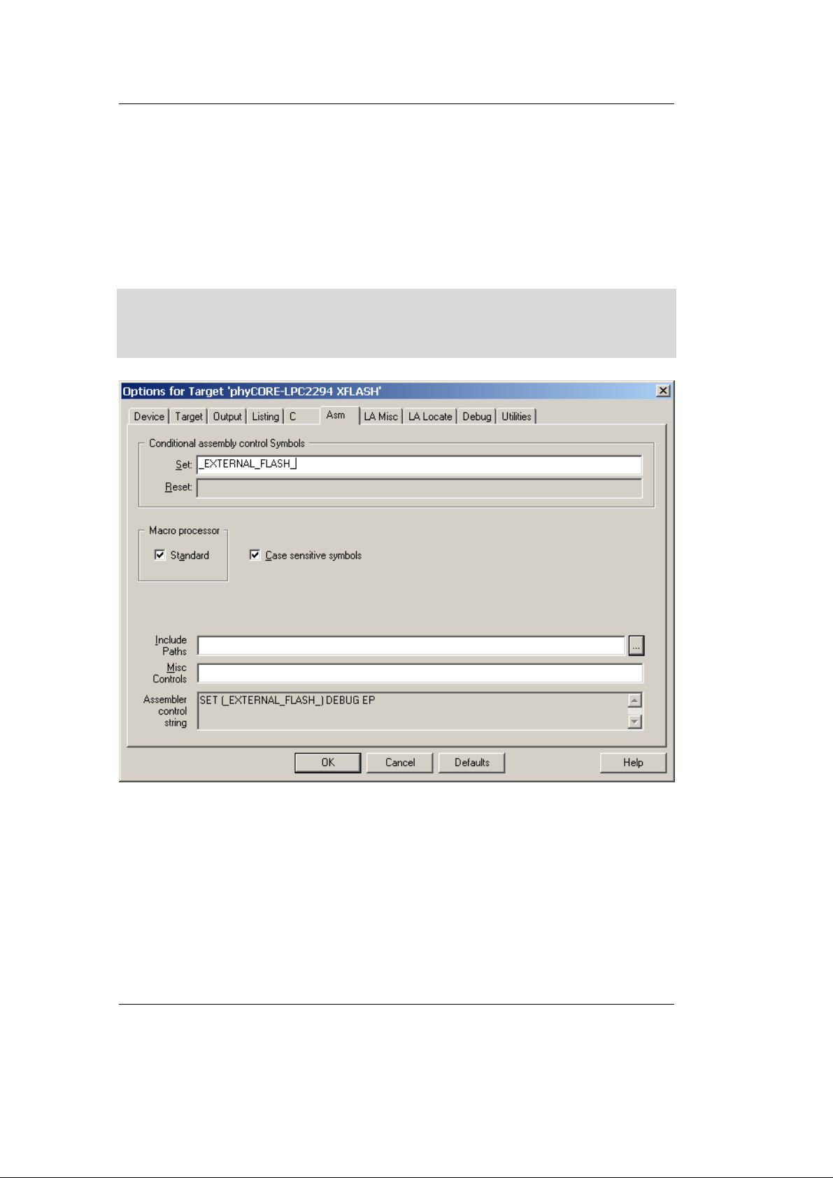
Configure the Asm Options
• Change to the Asm tab. In the Conditional assembly control
Symbols, Set field, type: _EXTERNAL_FLASH_. This will set
the LPC2294 MEMMAP register to User External Memory Mode,
where the interrupt vectors are re-mapped to external memory.
Note:
Please refer to the Philips LPC2294 User Manual section "Memory
Mapping Control" for more details.
46 © PHYTEC Messtechnik GmbH 2005 L-659e_3
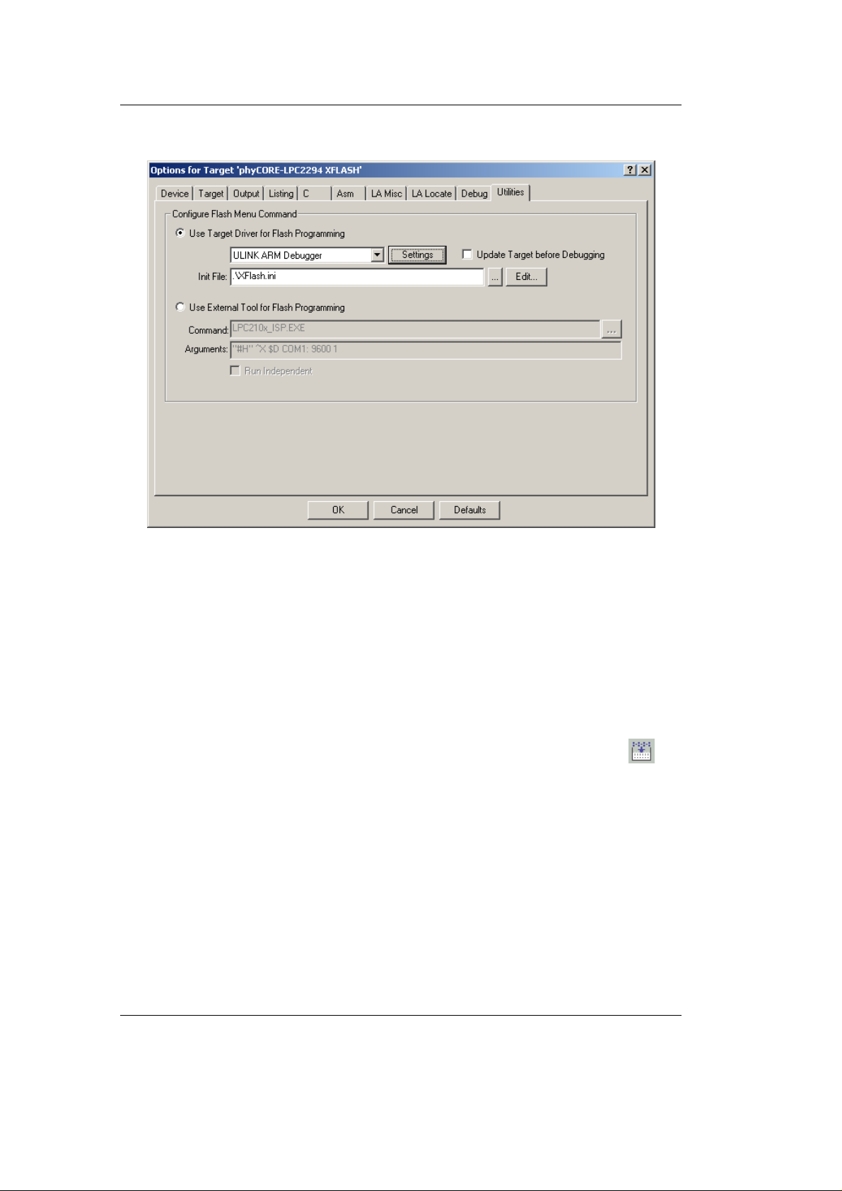
Page 51
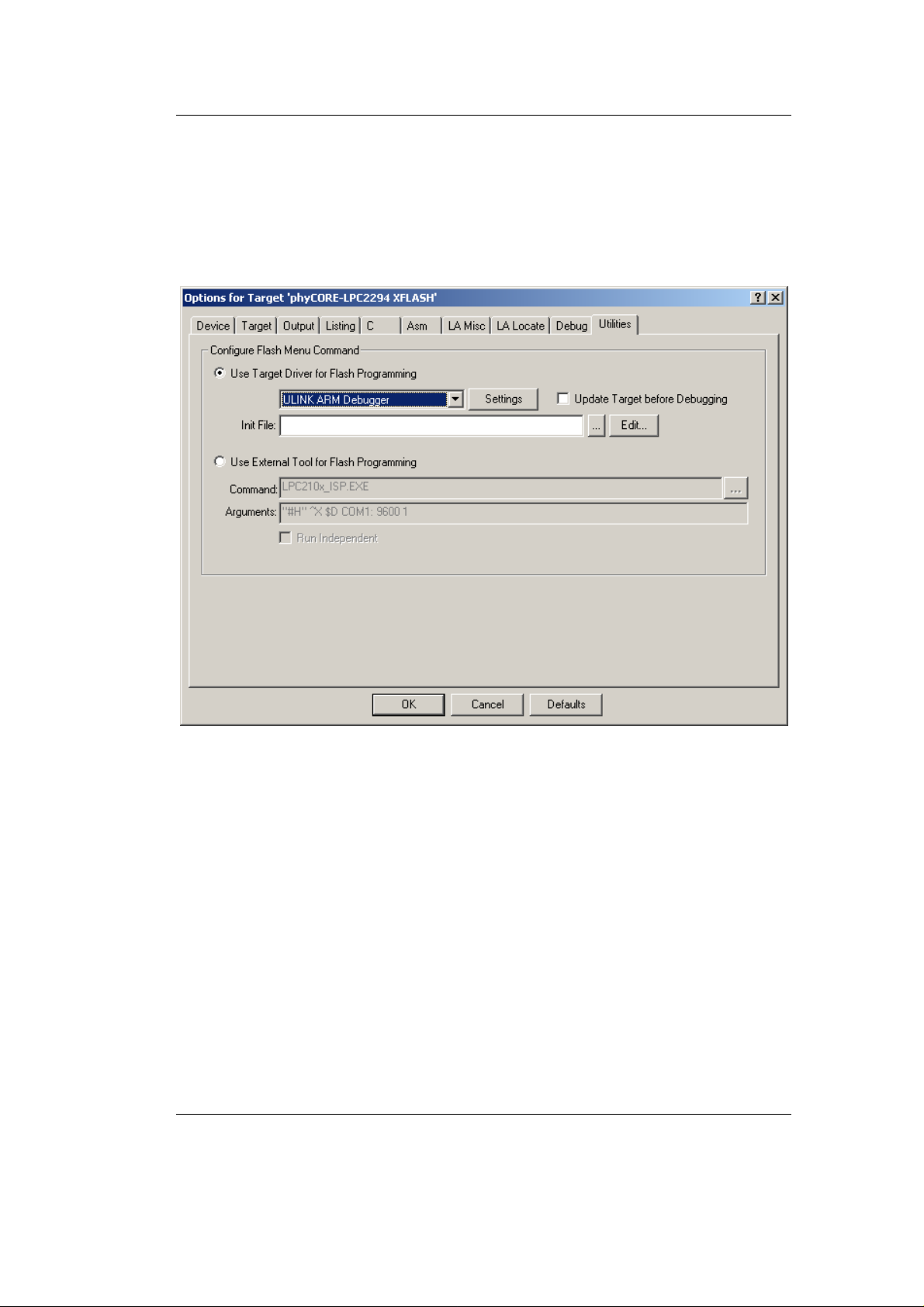
Configure the Utilities Options
• Select the Utilities tab.
• Select the Use Target Driver for Flash Programming option.
• In the pull-down menu select ULINK ARM Debugger.
Getting More Involved
• Click the Settings button.
© PHYTEC Messtechnik GmbH 2005 L-659e_3 47
Page 52
phyCORE-LPC2294 QuickStart Instructions
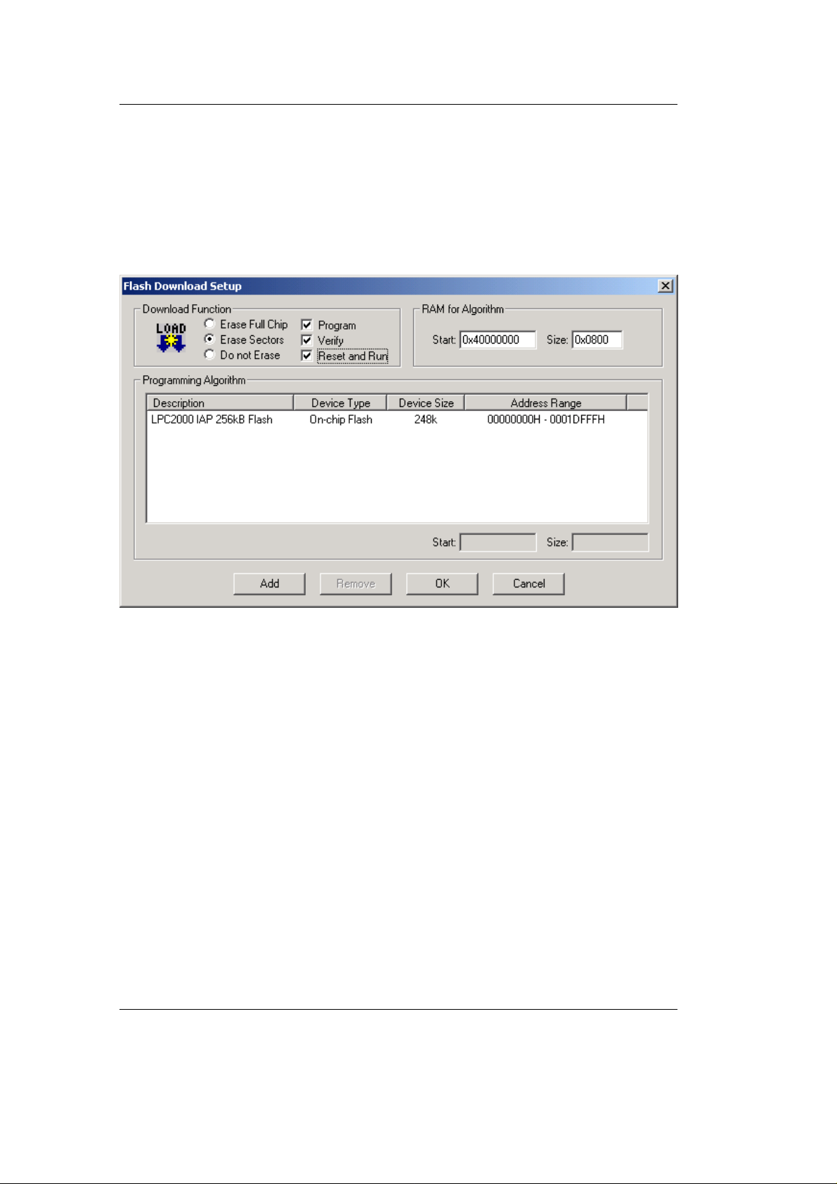
• In the Flash Download Setup window be sure that the following
Download Function options are selected: Program, Verify, and
Reset and Run. Checking the Reset and Run box will execute the
downloaded Blinky2 code at the end of the Flash programming
sequence without having to push the Reset button (S_2) on the
Development Board.
• Click on Add to add a Programming Algorithm.
48 © PHYTEC Messtechnik GmbH 2005 L-659e_3
Page 53
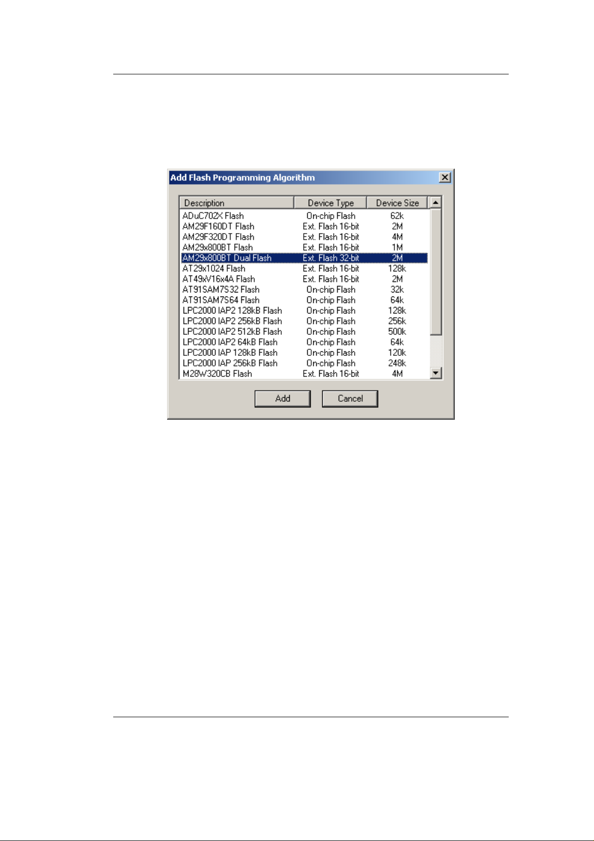
• In the Add Programming Algorithm window, select
AM29x800BT Dual Flash and click Add. The AM29DL800BT
device is the external Flash memory populating the
Getting More Involved
phyCORE
-LPC2294 module.
• Click on Add.
© PHYTEC Messtechnik GmbH 2005 L-659e_3 49
Page 54
phyCORE-LPC2294 QuickStart Instructions
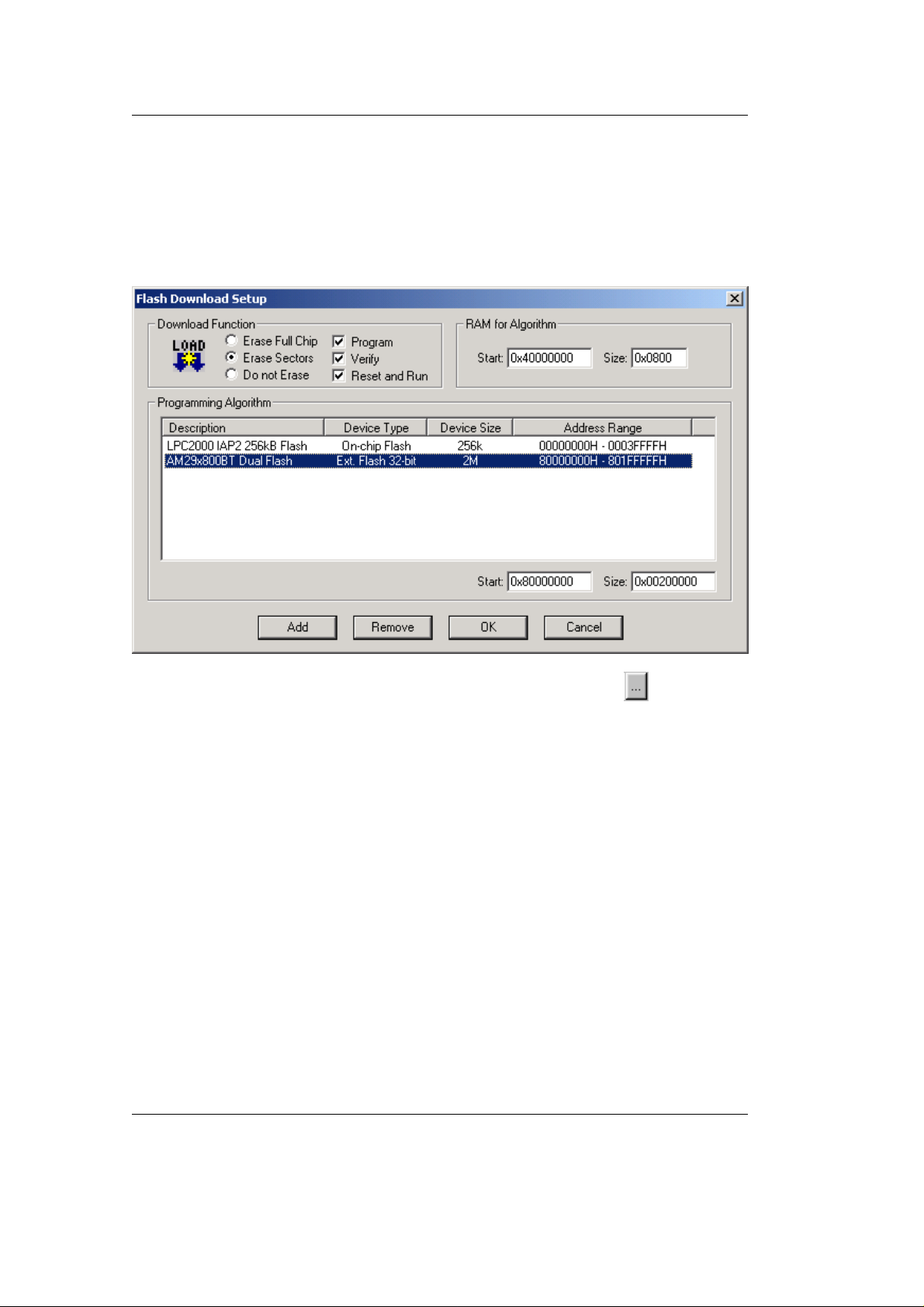
• In the RAM for Algorithm fields, set the Start address to
0x40000000 and address Size to 0x0800 as shown below.
• In the Programming Algorithm window click on the AM29x800BT
Dual Flash device and set the Start address to 0x80000000 and
Size to 0x00200000 as shown below and click OK.
• Back in the Utilities tab, select the browse button in the Init
File: line to add the Flash initialization file.
50 © PHYTEC Messtechnik GmbH 2005 L-659e_3
Page 55
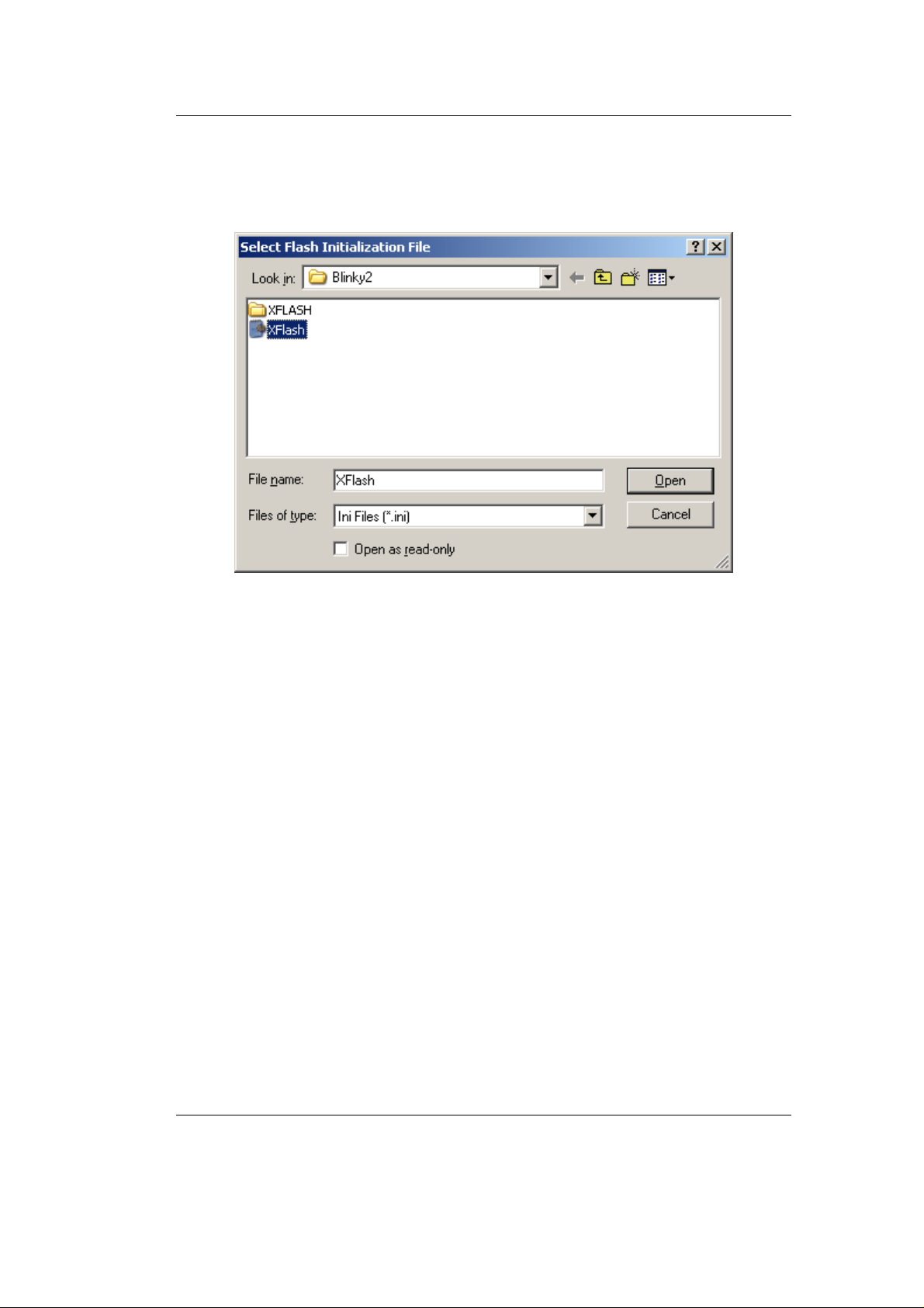
• In the Select Flash Initialization File pop-up window browse to
C:\PHYBasic\pC-LPC2294\Demos\Keil\Blinky2 and select the
XFlash.ini file.
Getting More Involved
• Click the Open button.
© PHYTEC Messtechnik GmbH 2005 L-659e_3 51
Page 56
phyCORE-LPC2294 QuickStart Instructions
The Utilities tab should appear as follows:
• Click Ok.
• In the main µVision3 menu select File / Save All.
3.4 Building the Project
You are now ready to run the compiler and linker using the Make
utility.
• Build the desired target by either selecting the build icon
the build toolbar or in the main menu select Project / Build target.
If any source file of the project contains any errors, they will be
shown in the Output Window - Build tab. Use the editor to correct
the error(s) in the source code and save the file and repeat the build.
If there are no errors, the code is ready to be downloaded into the
Flash memory.
on
52 © PHYTEC Messtechnik GmbH 2005 L-659e_3
Page 57
3.5 Downloading Code into Flash Memory
• In the Select Target pull down menu be sure that the
phyCORE-LPC2294 XFLASH target is selected.
• Download the code into Flash memory by either selecting the
Getting More Involved
Download to Flash Memory icon
on the build toolbar or in the
main menu select Flash / Download.
• Wait until the programming is complete. This is indicated by the
"Verify OK" message. The download utility will perform a reset
and the code will execute without further user interaction.
Successful execution of the program will flash the LED D3 with equal
on and off duration but with longer cycles compared to the original
Blinky demo.
You have now modified source code, recompiled the code, created a
downloadable file, and successfully executed this modified code.
Before starting with the following debugging section we need to erase
the external Flash.
• In the main µVision3 menu select Flash /Erase.
• The Flash erase status will be displayed at the bottom of the
µVision3 window and take a few seconds.
© PHYTEC Messtechnik GmbH 2005 L-659e_3 53
Page 58

phyCORE-LPC2294 QuickStart Instructions
54 © PHYTEC Messtechnik GmbH 2005 L-659e_3
Page 59

4 Debugging
This Debugging section provides a basic introduction to the debug
functions included in the Keil ARM7/µ Vision3 evaluation tool chain.
Using an existing example, the more important features are described.
For a more detailed description of the debugging features, please
refer to the appropriate manuals provided by Keil.
The µVision3 Debugger offers two operating modes that can be
selected in the Project|Options for Target phyCORE-LPC2292/94
dialog:
• The Simulator allows PC-based simulation of most features of the
LPC2294 microcontroller without actually having target hardware.
You can test and debug your embedded application before the
hardware is ready. µVision3 simulates a wide variety of
peripherals, including external I/O and timers. The peripheral set is
configured when you select a CPU from the device database for
your target.
Debugging
• USB-JTAG debugging interface adapters such as the Keil
ULINK, allow target-based debugging. With the ULINK interface
you may connect directly to the target hardware using the JTAG
interface. Debugging on the target hardware also enables the
testing of peripheral components of the application and real-time
program execution.
The following examples utilize the ULINK ARM Debugger
environment.
© PHYTEC Messtechnik GmbH 2005 L-659e_3 55
Page 60
phyCORE-LPC2294 QuickStart Instructions
4.1 Creating a Debug Project and Preparing the Debugger
4.1.1 Creating a New Project
• Start the Keil µVision3 environment and close all projects that
might be open.
• Open the Project menu and create a New Project called
Debug.uv2 within the existing project directory
C:\PHYBasic\pC-LPC2294\Demos\Keil\Debug
(default location) on your hard drive. Select the Philips LPC2294
in the CPU Vendor Data base list.
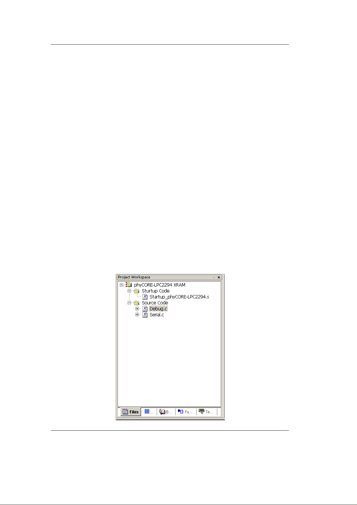
• Rename the target of your project within the Project Workspace
window - Files tab into phyCORE-LPC2294 XRAM.
• Rename the file group Source Group 1 as Startup Code and add
one additional file group named Source Code.
• Add Startup_phyCORE-LPC2294.s to the file group Startup
Code, (In the File of type pull-down menu, select: "Asm Source
file (*.s*; *.src*; .a*)" to see this file).
• Add the files Debug.c and Serial.c to the file group Source Code
from within the Project Workspace.
• Your project should now appear as follows:
56 © PHYTEC Messtechnik GmbH 2005 L-659e_3
Page 61

• Go to Project / Components, Environment, Books… from the
Debugging
menu or select the
icon on the toolbar. Select the
Folders/Extensions tab and be sure that Use Keil ARM Tools
under Select ARM Development Tools box is selected.
• Save the project.
• Double-click on the Debug.c file to open the source code window.
At this point you have created a project called Debug.uv2, consisting
of the C source files called Debug.c and Serial.c and the assembler
file Startup_phyCORE-LPC2294.s.
4.1.2 Setting Options for Target
• In the Select Target pull-down menu make sure the
phyCORE-LPC2294 XRAM target is selected.
• Configure options for target by selecting the Options for Target
icon
on the build toolbar or right-click on the
phyCORE-LPC2294 XRAM target in the Project Workspace
window and select Options for Target ’phyCORE-LPC2294
XRAM’.
© PHYTEC Messtechnik GmbH 2005 L-659e_3 57
Page 62
phyCORE-LPC2294 QuickStart Instructions
Configure the Target Options
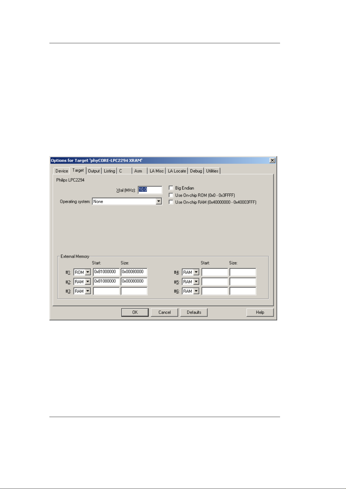
• In the Target tab be sure that Xtal is set to 10 MHz, and
Use On-chip ROM (0x0-0x3FFFF) as well as Use On-chip RAM
(0x40000000-0x40003FFF) are not checked. Set the External
Memory #1 to ROM and #2 to RAM and set the Start and Size as
follows:
ROM: 0x8100 0000 (Start) 0x0008 0000 (Size)
RAM: 0x8108 0000 (Start) 0x0008 0000 (Size)
It is necessary to configure the External Memory Start and Size
settings so that the combined user code and data does not exceed the
physical size of the RAM. The phyCORE
-LPC2294 standard version
features 1 MByte of external SRAM.
58 © PHYTEC Messtechnik GmbH 2005 L-659e_3
Page 63
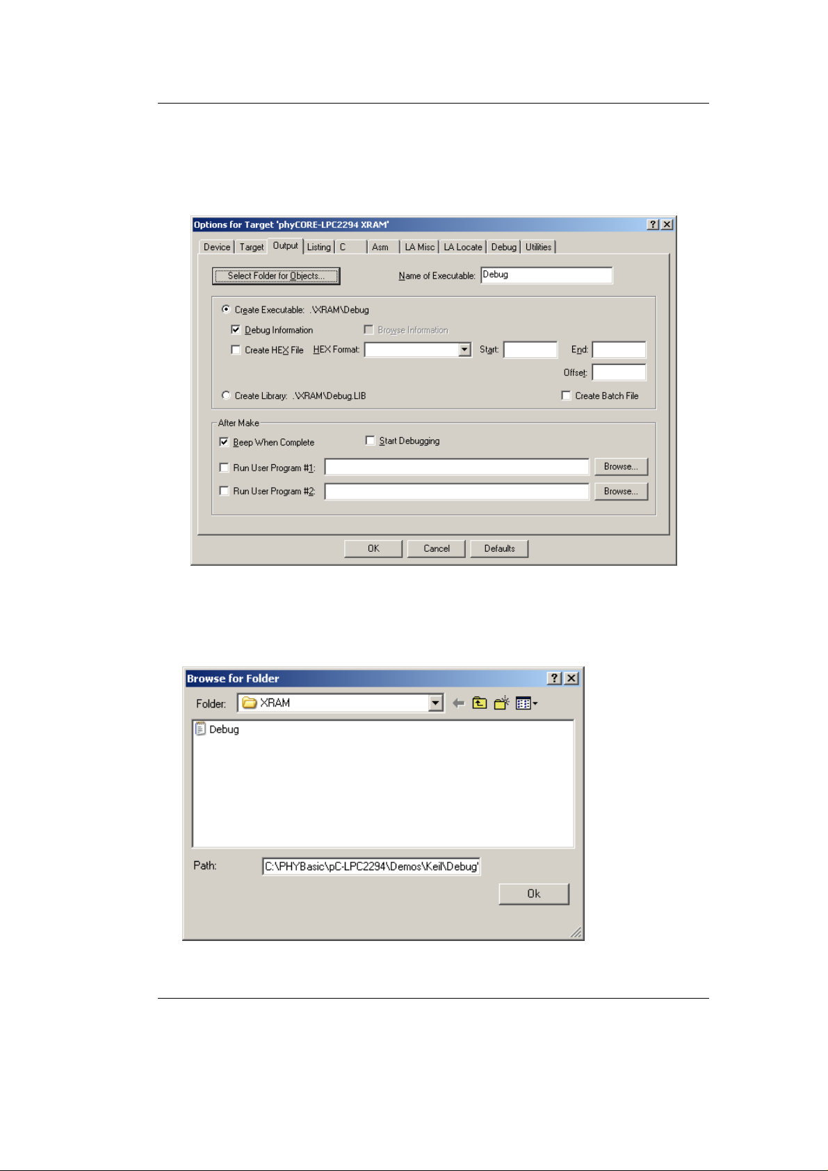
Configure the Output Options
• In the Output tab be sure that Create Executable, Debug
Information and Beep When Complete options are selected.
Debugging
• Click on the Select Folder for Objects button.
• Browse to the folder:
C:\PHYBasic\pC-LPC2294\Demos\Keil\Debug\XRAM.
• Click Ok.
© PHYTEC Messtechnik GmbH 2005 L-659e_3 59
Page 64
phyCORE-LPC2294 QuickStart Instructions
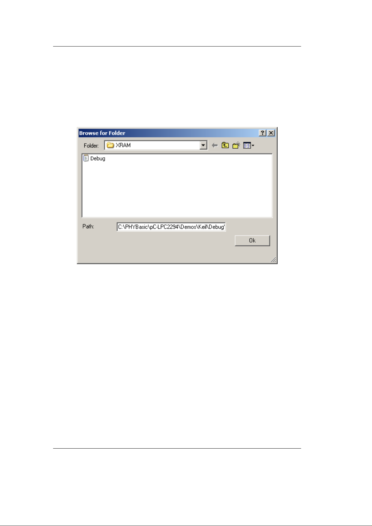
Configure the Listing Options
• In the Listing tab, leave the default settings.
• Click on the Select Folder for Listings button.
• Browse to the folder:
C:\PHYBasic\pC-LPC2294\Demos\Keil\Debug\XRAM.
• Click Ok.
60 © PHYTEC Messtechnik GmbH 2005 L-659e_3
Page 65
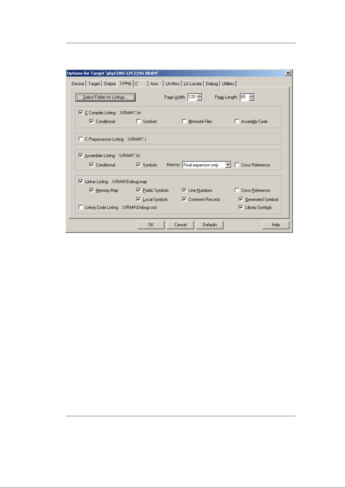
• The Listing tab should appear as follows:
Debugging
© PHYTEC Messtechnik GmbH 2005 L-659e_3 61
Page 66
phyCORE-LPC2294 QuickStart Instructions
Configure the Asm Options
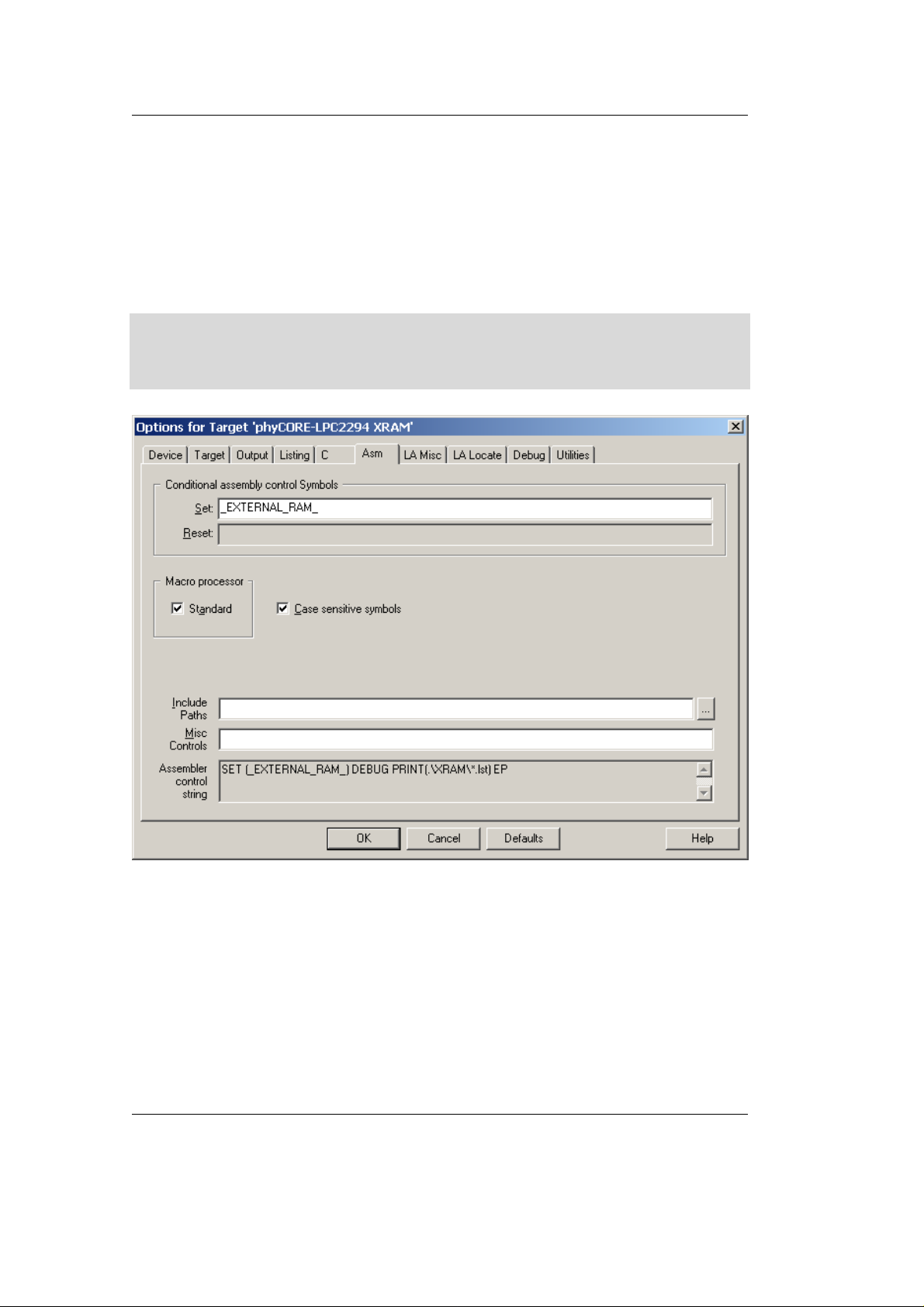
• Change to the Asm tab. In the Conditional assembly control
Symbols, Set field, type: _EXTERNAL_RAM_. This will set the
LPC2294 MEMMAP register to User RAM Mode, where the
interrupt vectors are re-mapped to static RAM.
Note:
Please refer to the Philips LPC2294 User Manual section "Memory
Mapping Control" for more details.
62 © PHYTEC Messtechnik GmbH 2005 L-659e_3
Page 67
Configure the Debug Options
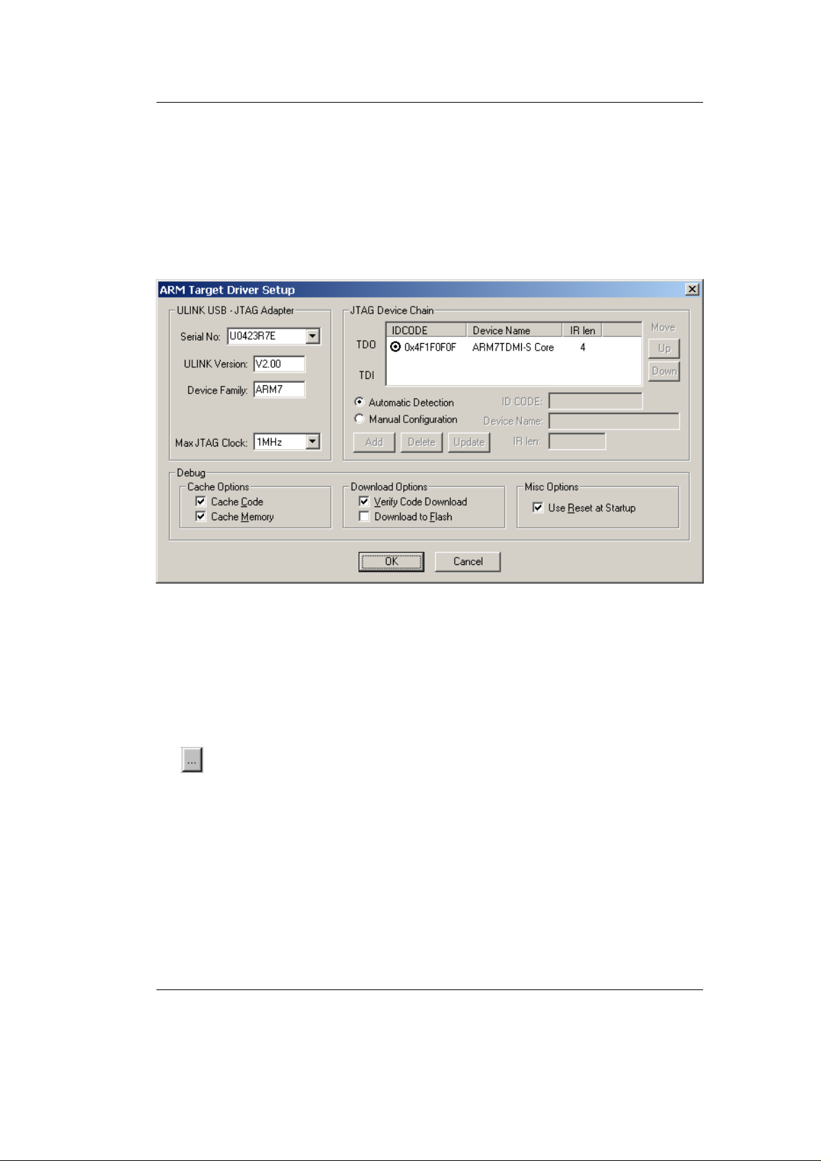
• In the Debug tab, check the Use: ULINK ARM Debugger option.
• Configure the ARM Target Driver Setup by clicking the Settings
button. The ARM Target Driver Setup settings should be as
follows:
Debugging
• Click OK to return to the Options for Target window.
• Be sure that the Load Application at Startup, under the ULINK
ARM Debugger setting, is NOT checked. Loading the application
code and the go till main function are executed by the XRAM.ini
file (see below).
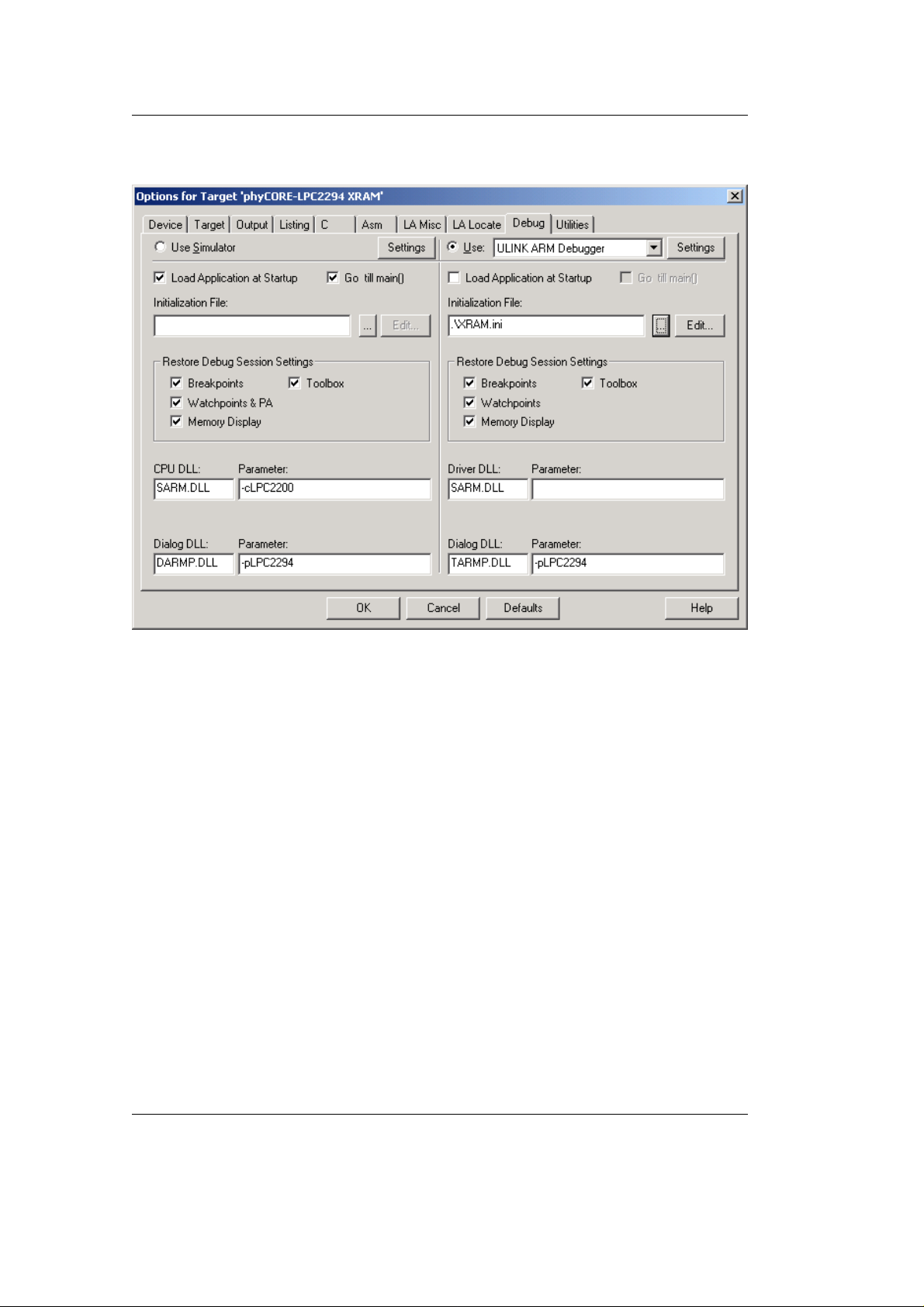
• Add the correct Initialization File by clicking the browse button
and select XRAM.ini.
© PHYTEC Messtechnik GmbH 2005 L-659e_3 63
Page 68
phyCORE-LPC2294 QuickStart Instructions
• The Debug tab should now appear as follows:
• Click OK to save all the settings.
• In the main µVision3 menu select File / Save All.
64 © PHYTEC Messtechnik GmbH 2005 L-659e_3
Page 69

You are now ready to run the compiler and linker using the Make
utility.
Debugging
• Build the target by either selecting the build icon
on the build
toolbar or in the main menu select Project / Build target.
If there are no errors, the code is ready to be downloaded into the
external SRAM for further debugging steps. Before starting the
debugger first open HyperTerminal again using the same settings as
described in section 2.4.2. This allows you to monitor the
printf
outputs over the RS-232 port.
4.2 Starting the Debugger
• To start the ARM7/µVision3 debug environment, click on the
debugger icon
• You will see a blue status bar from left to right at the bottom of
your screen indicating the download process of the debug
program.
If a problem occurs during data transfer, an error message will be
displayed. If this should occur, make sure the target hardware is
properly connected to a power supply and the host-PC using the Keil
ULINK device (refer to section 2.2).
on the µVision3 toolbar.
© PHYTEC Messtechnik GmbH 2005 L-659e_3 65
Page 70
phyCORE-LPC2294 QuickStart Instructions
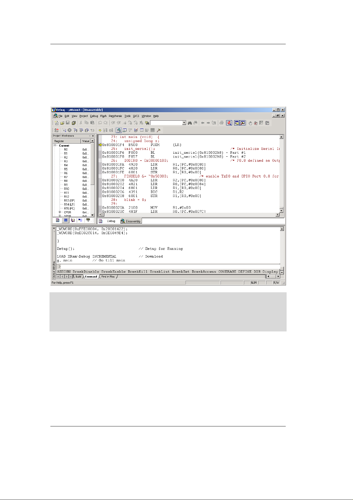
If the data transfer was successful, a screen similar to the one shown
below will appear. The Project window changes to the Register page
and the Disassembly window becomes active. The debug toolbar is
also displayed. In the lower part of the debug screen you will see the
Comm and and Watch windows.
You may need to open, resize and /or move some windows to make
your screen look similar to the screen capture. You can open inactive
windows by choosing the desired window from the View pull-down
menu.
• Change to the Debug.c source window by clicking on the
corresponding tab.
The debugger will run to the ’main’ function and stop automatically.
Notice the yellow arrow pointing to the first command in the ’main’
function. Also notice the program counter (PC $) within the Project
Window – Register page showing the start address of the ’main’
function.
66 © PHYTEC Messtechnik GmbH 2005 L-659e_3
Page 71
4.3 Keil µVision3 Debug Features
Debugging
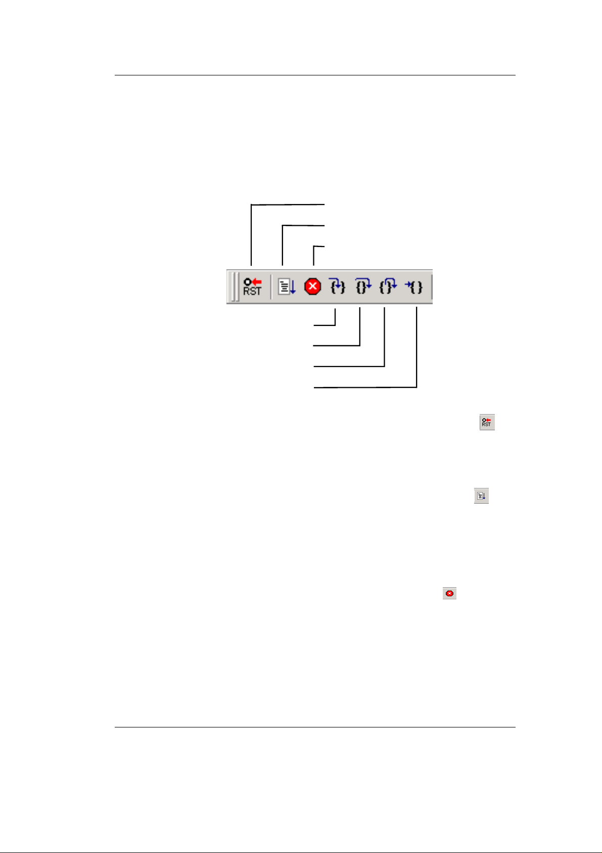
• The Debugger window toolbar gives access to the following
debug commands: Reset, Run, Stop, Step Into, Step Over, Step Out
and Run to Cursor line .
Reset
Run
Stop
Step Into
Step Over
Step Out
Run to Cursor lin e
• The first button on the debugger toolbar is the Reset
button.
The Reset command sets the program counter to 0.
• The button to the right of the Reset button starts the Run
comma nd.
Clicking this button runs the program without active debug
functions. To stop program execution at a desired point, a
breakpoint can be placed before the Run button is pushed.
• The next button on the debugger toolbar is the Stop button.
The Stop button interrupts and stops the running program at an
undetermined location.
© PHYTEC Messtechnik GmbH 2005 L-659e_3 67
Page 72

phyCORE-LPC2294 QuickStart Instructions
• The first button allowing exact control of the program execution is
the Step Into button.
The Step Into command performs the execution of the command
line to which the Current-Statement Arrow points. This can
be a C command line or a single assembler line, depending on the
current display mode. If the command line is a function call, Step
Into jumps to the C function or subroutine, enabling you to explore
the code contained in the accessed subroutine.
• The Step Over button is next on the debugger toolbar.
The Step Over command executes the command line, to which the
Current-Statement Arrow points. This can be a C command
line or a single assembler line, depending on the current display
mode. If the command line is a function call, the function will be
executed without single stepping into the function.
• The next button is the Step Out button..
Step Out is used to exit a function you are currently in. Step Out is
very useful if you find yourself in a function you are not interested
in and need to return quickly to your intended function.
• The last button on the debugger toolbar performs the Run to
Cursor line command.
The Run to Cursor line command executes the program to the
current cursor position within the code window. This allows use of
the cursor line as a temporary breakpoint.
68 © PHYTEC Messtechnik GmbH 2005 L-659e_3
Page 73
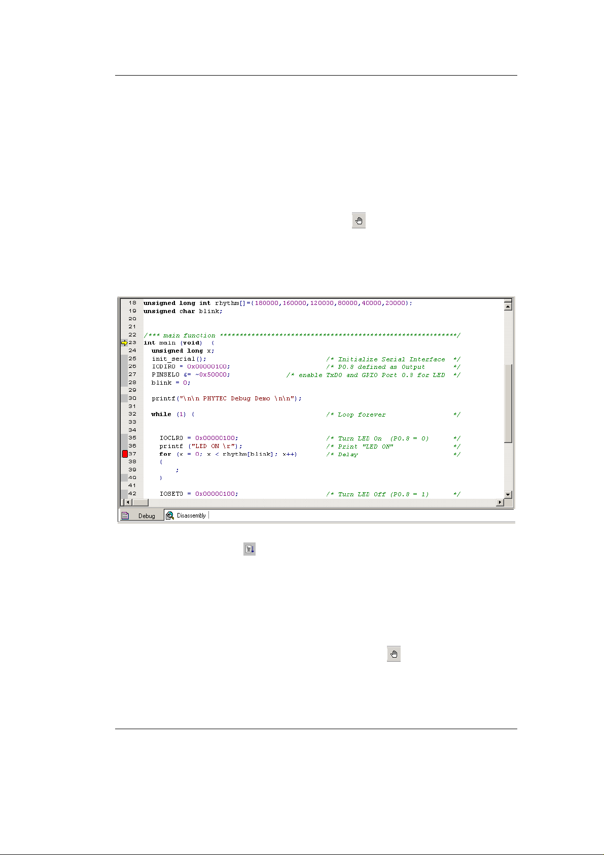
4.4 Using the Keil µVision3 Debug Features
4.4.1 Breakpoints
• Activate the Debug.c file by clicking on the Debug tab.
Debugging
• Click in the source code, line 37,
for (x = 0; x < rhythm[blink]; x++)
at
• Click on Insert/Remove Breakpoint to set a breakpoint here.
The red marker on the left-hand side of the selected line indicates
the breakpoint. You can also set a breakpoint by double-clicking
in the desired code line.
• Click on the Run icon and the program will run and stop at
the breakpoint.
• Notice that the LED (D3) on the Development Board now
illuminates.
• Also notice the output message in HyperTerminal that comes from
the
printf statement in line # 30 and #36.
• Click again on Insert/Remove Breakpoint to remove the
breakpoint.
© PHYTEC Messtechnik GmbH 2005 L-659e_3 69
Page 74
phyCORE-LPC2294 QuickStart Instructions
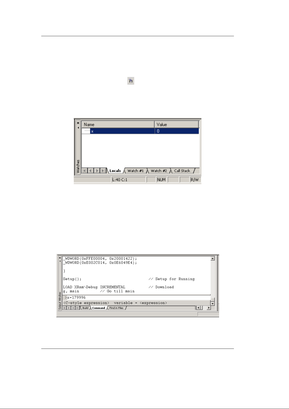
4.4.2 Single Stepping and Watch Window
• Open the Watch and Call Stack Window from the View pull-
down menu.
• Click on the Step Into icon to enter the
for{}
loop.
• The Watch window – Locals tab automatically shows the value
of the local variable x. Change the number base from hexadecimal
to decimal by right-clicking on the variable.
• Click Step Over several times and watch the value of x count up.
• As you can see in the source code, the
for{}
loop will end if x
becomes equal to the first element of the constant field rhythm[]
which has the value of 180,000. To leave the wait function,
change the value of x by typing x=179996 in the command line
and press <Enter>. Now repeat clicking on Step Over until you
leave the wait function.
70 © PHYTEC Messtechnik GmbH 2005 L-659e_3
Page 75
• Click in the source code, line 44, at blink++ and choose Run to
Cursor line from the debug toolbar. Your program will be
executed until it reaches this line.
• Notice that the LED D3 on the Development Board is off now and
a new output message appeared in your H yperTerminal window.
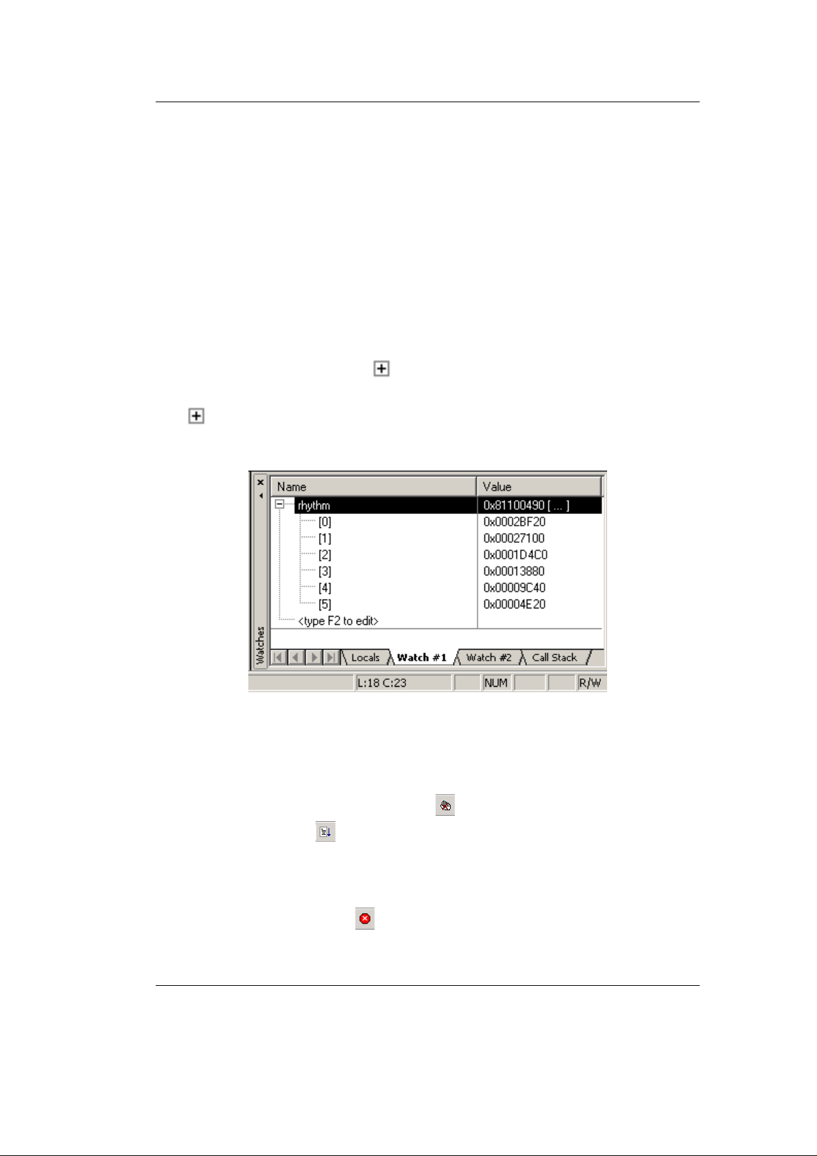
• As a last example, the constant "rhythm[]" will be evaluated. Go
to source code line #18 where the constant "rhythm[]" is declared.
Right-click on "rhythm[]" and choose the "ADD rhythm to
watch window" -> #1 option. Select the "Watch #1" tab at the
bottom of the watch window. The constant is shown with its
address and a small sign in front which indicates that
"rhythm[]" is an array with a group of array elements. Click the
sign to expand the view and to see all array elements of
"rhythm[]".
Debugging
4.5 Running, Stopping and Resetting
• To run your program without stopping at any time, delete all
breakpoints by clicking on the button.
• Click the Run button.
The LED now blinks at changing on/off intervalls.
You can use the Stop button to stop program execution at any
time.
© PHYTEC Messtechnik GmbH 2005 L-659e_3 71
Page 76

phyCORE-LPC2294 QuickStart Instructions
4.6 Changing Target Settings for the "Executable V ersion"
After successfully debugging the program, next change the project
and the target settings in order to create an executable file that can
then be downloaded to and executed out of the Flash memory on the
phyCORE
• Make sure the program execution is stopped.
• Exit the current debug session by selecting Debug|Start|Stop
Debug Session.
• We recommend adding a new target to the debug project. This
allows you to use the same C source files but different target
settings to be used for debugging (XRAM) and Flash download
(XFLASH).
-LPC2294.
• Click on the
• Add another target by selecting the New(Insert) icon
icon in the build toolbar.
in the
Project targets window. Name the new target
phyCORE-LPC2294 XFLASH .
• Click OK to return to the µVision3 window.
• In the Select Target pull down menu select
phyCORE-LPC2294 XFLASH.
• Configure options for target by selecting the Options for Target
icon
on the build toolbar.
• Set all target options as described in section 3.3 and build the
project.
• Download the created Debug file to the external Flash memory.
For general download procedure information refer to section 3.5.
• Start the HyperTerminal program as described in section 2.4.2.
• The Debug code will start automatically at the end of the
download.
Now you can watch your final debug example execute. The
HyperTerminal will display the status of the LED.
72 © PHYTEC Messtechnik GmbH 2005 L-659e_3
Page 77

Document: phyCORE-LPC2294 QuickStart Instructions
Document number: L-659e_3, June 2005
How would you improve this manual?
Did you find any mistakes in this manual? page
Suggestions for Improvement
Submitted by:
Customer number:
Name:
Company:
Address:
Return to:
PHYTEC America LLC
203 Parfitt Way SW, Suite G100
Bainbridge Island, WA 98110
Fax : (206) 780-9135
© PHYTEC Messtechnik GmbH 2005 L-659e_3
Page 78

Published by
PHYTEC Messtechnik GmbH 2005 Ordering No. L-659e_3
Printed in Germany
 Loading...