

Page 1

phyCORE®-AM335x
QuickStart Instructions
Document No.: L-779e_6
Release Nos.: SO-498v6
PD15.2.1
Ubuntu 14.04
Edition: April 2016
A product of a PHYTEC Technology Holding company
Page 2

phyCORE®-AM335x [PCM-051-xxx]
Copyrighted products are not explicitly indicated in this manual. The absence of the trademark (™, or ®)
and copyright (©) symbols does not imply that a product is not protected. Additionally, registered patents
and trademarks are similarly not expressly indicated in this manual.
The information in this document has been carefully checked and is considered to be entirely reliable.
However, PHYTEC Messtechnik GmbH assumes no responsibility for any inaccuracies. PHYTEC Messtechnik
GmbH neither gives any guarantee nor accepts any liability whatsoever for consequential damages
resulting from the use of this manual or its associated product. PHYTEC Messtechnik GmbH reserves the
right to alter the information contained herein without prior notification and accepts no responsibility for
any damages that might result.
Additionally, PHYTEC Messtechnik GmbH offers no guarantee nor accepts any liability for damages arising
from the improper usage or improper installation of the hardware or software. PHYTEC Messtechnik GmbH
further reserves the right to alter the layout and/or design of the hardware without prior notification and
accepts no liability for doing so.
© Copyright 2016 PHYTEC Messtechnik GmbH, D-55129 Mainz.
Rights - including those of translation, reprint, broadcast, photomechanical or similar reproduction and
storage or processing in computer systems, in whole or in part - are reserved. No reproduction may occur
without the express written consent from PHYTEC Messtechnik GmbH.
EUROPE NORTH AMERICA FRANCE
Address: PHYTEC Messtechnik GmbH
Robert-Koch-Str. 39
D-55129 Mainz
GERMANY
Sales:
Technical
Support:
+49 6131 9221-32
+49 6131 9221-31
PHYTEC America LLC
203 Parfitt Way SW
Bainbridge Island, WA 98110
USA
+1 800 278-9913
+1 206 780-9047
PHYTEC France
17, place Saint-Etienne
F-72140 Sillé-le-Guillaume
FRANCE
+33 2 43 29 22 33
Fax: +49 6131 9221-33 +1 206 780-9135 +33 2 43 29 22 34
Web Site:
http://www.phytec.de
http://www.phytec.eu
http://www.phytec.com http://www.phytec.fr
INDIA CHINA
Address: PHYTEC Embedded Pvt. Ltd.
#16/9C, 3rd Main, 3rd Floor, 8th Block,
Opp. Police Station Koramangala,
Bangalore-560095
INDIA
Sales:
+91-80-4086 7046/48
PHYTEC Information Technology (Shenzhen) Co. Ltd.
Suite 2611, Floor 26, Anlian Plaza,
4018 Jin Tian Road
Futian District, Shenzhen
CHINA 518026
+86-755-3395-5875
Technical
Support:
+91-80-4086 7047
Fax: +86-755-3395-5999
Web Site: http://www.phytec.in http://www.phytec.cn
6th Edition April 2016
© PHYTEC Messtechnik GmbH 2016 L-779e_6
Page 3

Contents
Conventions, Abbreviations and Acronyms ....................................................................iii
1 Introduction ...................................................................................................... 1
1.1 Rapid Development Kit Documentation ............................................................. 1
1.2 Professional Support Packages Available ........................................................... 1
1.3 Overview of these QuickStart Instructions .......................................................... 2
1.4 System Requirements .................................................................................... 2
1.5 Software used in the Virtual Machine Hard Disk Image.......................................... 2
1.5.1 Ubuntu............................................................................................ 2
1.5.2 Eclipse............................................................................................. 3
1.5.3 Qt Creator ........................................................................................ 3
1.5.4 Yocto Project .................................................................................... 3
2 Getting Started................................................................................................... 5
2.1 Preparing and Starting the virtual machine ........................................................ 5
2.2 Starting the Hardware ................................................................................... 7
3 Working with Eclipse ......................................................................................... 13
3.1 Programming in the C/C++ Perspective.............................................................13
3.1.1 Work with the Demo Project ................................................................13
3.1.2 Creating a New Project.......................................................................18
3.1.3 Modifying the Demo Application ..........................................................25
3.1.4 Starting a Program out of Eclipse on the Target.......................................27
3.2 Debugging an Example Project .......................................................................29
3.2.1 Starting the GDB Server on the Target ...................................................30
3.2.2 Configuring and Starting the Debugger in Eclipse....................................30
3.2.3 Setting a Breakpoint .........................................................................35
3.2.4 Stepping through and Watching Variable Contents ..................................36
3.2.5 Stepping through and Changing Variable Contents ..................................38
3.2.6 Using the Memory Monitor..................................................................39
4 Working with Qt Creator..................................................................................... 43
4.1 Stop the Running Qt Demo on the Target ..........................................................43
4.2 Importing the Demo Application .....................................................................44
4.3 Work with the Demo Application .....................................................................46
4.4 Compile and Run the Demo Application on the Target..........................................49
4.5 Compile and Run the Demo Application on the Host............................................51
4.6 Debugging the Demo Application ....................................................................53
4.6.1 Using QDebug for simple Debugging Messages........................................53
4.6.2 Using the integrated Qt Creator Debugger .............................................55
5 Getting Started with the BSP .............................................................................. 59
5.1 Add new Packages to the Root Filesystem with Yocto...........................................59
5.2 Writing the Root Filesystem into the Target’s Flash .............................................63
© PHYTEC Messtechnik GmbH 2016 L-779e_6 i
Page 4

phyCORE®-AM335x [PCM-051-xxx]
6 Setup your own Linux Host PC ............................................................................. 67
6.1 Essential Settings ....................................................................................... 67
6.1.1 Installing Ubuntu ............................................................................ 67
6.1.2 Installation of Software Packages........................................................ 69
6.1.3 Set the Git Configuration ................................................................... 70
6.1.4 Build the Board Support Package and Install the SDK .............................. 70
6.1.5 Set up Eclipse and Integrate Plug-ins................................................... 72
6.1.6 Install and Setup Qt Creator................................................................ 74
6.1.7 Setting up a TFTP server..................................................................... 81
6.1.8 Optional Settings............................................................................. 82
7 Revision History................................................................................................ 83
© PHYTEC Messtechnik GmbH 2016 L-779e_6
ii
Page 5

Conventions, Abbreviations and Acronyms
Conventions, Abbreviations and Acronyms
The following is a list of the typographical conventions used in this book:
Conventions
The conventions used in this manual are as follows:
Signals that are preceded by an "n", "/", or “#”character (e.g.: nRD, /RD, or #RD), or
that have a dash on top of the signal name (e.g.: RD) are designated as active low
signals. That is, their active state is when they are driven low, or are driving low.
A "0" indicates a logic zero or low-level signal, while a "1" represents a logic one or
high-level signal.
The hex-numbers given for addresses of I
address byte. The correct value of the LSB which depends on the desired command
(read (1), or write (0)) must be added to get the complete address byte. E.g. given
address in this manual 0x41 => complete address byte = 0x83 to read from the device
and 0x82 to write to the device.
Tables which describe jumper settings show the default position in bold, blue text.
Text in blue italic indicates a hyperlink within, or external to the document. Click these
links to quickly jump to the applicable URL, part, chapter, table, or figure.
Text in bold italic indicates an interaction by the user, which is defined on the screen.
Text in
Consolasindicates an input by the user, without a premade text or button to
click on.
Text in italic indicates proper names of development tools and corresponding controls
(windows, tabs, commands etc.) used within the development tool, no interaction
takes place.
White Text on black background shows the result of any user interaction (command,
program execution, etc.)
2
C devices always represent the 7 MSB of the
© PHYTEC Messtechnik GmbH 2016 L-779e_6 iii
Page 6
phyCORE®-AM335x [PCM-051-xxx]
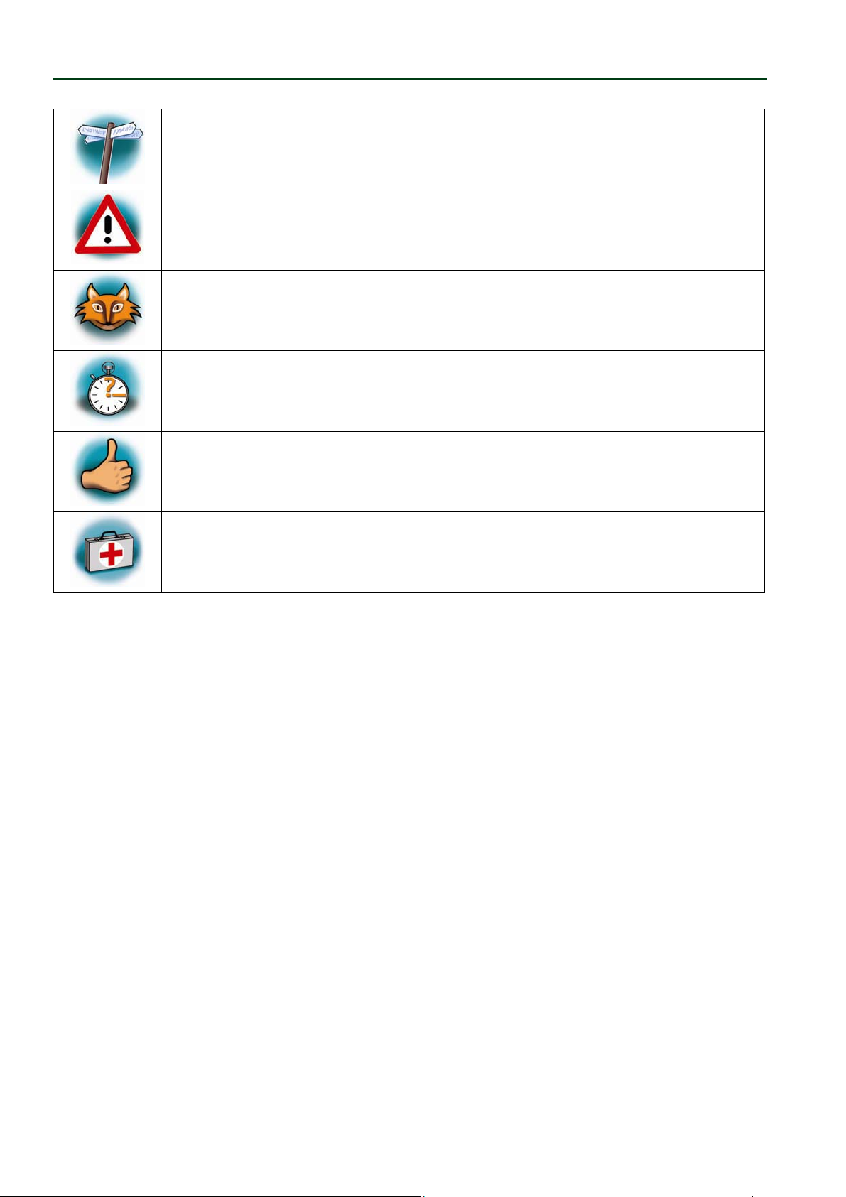
At this icon you might leave the path of this Application Guide.
This is a warning. It helps you to avoid annoying problems.
You can find useful supplementary information about the topic.
At the beginning of each chapter you can find information about the time
required to read the following chapter.
You have successfully completed an important part of this Application
Guide.
You can find information to solve problems.
© PHYTEC Messtechnik GmbH 2016 L-779e_6
iv
Page 7

Introduction
1 Introduction
In this QuickStart Instructions Manual you will find general information about the Phytec
phyCORE-AM335x Kit and instructions how to start up with the phyCORE-AM335x. You will
learn how to...
… use the prepared virtual machine hard disk image.
... connect to the target.
... handle with the Yocto Project and our Board Support Package to build your own images.
... work with Eclipse and Qt Creator .
... setup your own Linux host system.
This first section gives a short introduction on the Phytec phyCORE-AM335x Kit and its
QuickStart. Also, you will find general requirements and information to successfully pass the
QuickStart.
1.1 Rapid Development Kit Documentation
This
Rapid Development Kit
(RDK) includes the following electronic documentation on the
virtual machine's hard disk under /opt/PHYTEC_Tools/Documentation.
The Phytec phyCORE-AM335x Hardware Manual
Hardware schematics
The
Yocto
Reference Manual
The BSP Manual
These QuickStart Instructions
1.2 Professional Support Packages Available
If you have any questions concerning installation and setup, you are welcome to contact
our support department.
For more in-depth questions, we offer a variety of custom-tailored packages with different
support options (e-mail, phone, direct contact to the developer) and different reaction
times.
Please contact our sales team to discuss the appropriate support option if professional
support beyond installation and setup is important for you. For more information please
refer to the following sources:
http://www.phytec.de/support/support-pakete/
http://www.phytec.eu/europe/support/support-packages.html
[email protected]
More contact information can be found on page 2.
© PHYTEC Messtechnik GmbH 2016 L-779e_6 1
Page 8

phyCORE®-AM335x [PCM-051-xxx]
1.3 Overview of these QuickStart Instructions
This QuickStart gives you an overview of the phyCORE-AM335x. Its content ranges from the
first startup, to building your own kernel and file system, to the point of building your own
program with
Eclipse
The Getting Started section describes the basics such as configuring your host platform
and starting the phyCORE-AM335x platform.
The Working with Eclipse explains how to modify an example application, create, build,
debug a new project, and copy programs to the phyCORE-AM335x using Eclipse with the
C/C++ CDT plugin.
The Working with Qt Creator section explains how to modify an example application,
create, build, debug a new project, and copy programs to the phyCORE-AM335x using
Creator
.
and
Qt Creator
. This QuickStart is structured as follows:
Qt
The
Working with Yocto
section explains how to add new packages to our Board Support
Package, build a new root filesystem and copy the root filesystem into the target’s Flash.
The Setup your own Linux-Host-PC section explains how to setup your own Linux host PC if
you do not want to use our virtual machine hard disk image.
1.4 System Requirements
The following items will be needed to complete this QuickStart successfully:
The Phytec phyCORE-AM335x
The Phytec Development Board with the included DB-9 serial cable, Ethernet crossover
cable and AC adapter supplying 5 VDC (min. 2 A)
The Phytec virtual machine hard disk image (
SO-498v6
) available on the enclosed USB
flash drive
An IBM-compatible host-PC (586 or higher) with 512 MB RAM (or more)
1.5 Software used in the Virtual Machine Hard Disk Image
1.5.1 Ubuntu
Ubuntu - which is used as operating system for our virtual machine - is a free and open
source operating system based on Debian Linux. Basically it is designed for desktop use.
Web statistics suggest that Ubuntu is one of the most popular operating systems in the
Linux desktop environment.
The Ubuntu release which we deliver is 14.04.4 and was released on 18. February 2016.
Ubuntu 14.04 code name "Trusty Tahr" is designated as a Long Term Support (LTS) release
and the first stable release was on 17. April 2014. LTS means that it will be supported and
updated for five years.
© PHYTEC Messtechnik GmbH 2016 L-779e_6
2
Page 9

Introduction
Our Ubuntu version comes with Unity as desktop environment, dpkg as package
management system, the update method is based on APT (Advanced Packaging Tool) and
the user space uses GNU.
1.5.2 Eclipse
The Eclipse platform provides support for C/C++. Because the Eclipse platform is only a
framework for developer tools, it does not support C/C++ directly, instead it uses external
plug-ins. This QuickStart shows you how to make use of the CDT plug-in.
The CDT is an open source project (licensed under the Common Public License)
implemented purely in Java as a set of plug-ins for the Eclipse SDK platform. These plug-ins
add a C/C++ perspective to the Eclipse Workbench that can now support C/C++ development
with a number of views and wizards, along with advanced editing and debugging support.
1.5.3 Qt Creator
Qt Creator is a cross-platform development environment for the Qt framework. Included are
a code editor and a Qt Designer to build graphical user interfaces (GUI). It uses the GNU
C/C++ compiler.
1.5.4 Yocto Project
The Yocto Project is an open source collaboration to create custom Linux-based systems for
embedded products regardless of the hardware architecture. We use the Yocto Project to
create the Board Support Package (BSP) for our hardware.
© PHYTEC Messtechnik GmbH 2016 L-779e_6 3
Page 10

phyCORE®-AM335x [PCM-051-xxx]
© PHYTEC Messtechnik GmbH 2016 L-779e_6
4
Page 11
Getting Started
2 Getting Started
2.1 Preparing and Starting the virtual machine
To ensure successful introduction to the development with the
phyCORE-AM335x we strongly recommend continuing with the prepared
virtual machine hard disk image.
Nonetheless, if you want to use your already existing environment we
explain how to modify your system to get the same experience as with our
virtual machine in section 6. Please be advised that use of your already
existing environment is on your own risk. We can not guarantee to
successfully support you with your own environment.
To follow this QuickStart you need our phyCORE-AM335x virtual machine hard disk image.
The hard disk image includes all software installations and configurations (e.g. pre-built
Yocto BSP, Eclipse, Qt Creator) necessary for a successful start-up of the phyCORE-AM335x.
The compressed image (SO-498v6.zip) on the enclosed USB flash drive includes the virtual
machine disk file (.vmdk). It is suitable for most virtualization software, and can be
mounted to an appropriate virtual machine (tested with VMware Player and VirtualBox).
The SO-498v6.vmdk included in the compressed image is not a complete
virtual machine, it is solely a hard disk image.
Perform the following steps to mount the virtual machine disk file (.vmdk):
1. Plug in the USB flash drive.
2. Unpack the compressed VM hard disk image from the USB flash drive to your hard
disk.
3. Follow the instructions of your virtualization software to create a new virtual
machine. However, pay regard to the following settings required to obtain a
correctly working virtual machine:
- choose Linux-Ubuntu 64-bit version as operating system
- use the file SO-498v6.vmdk as hard disk (in Virtualbox you will choose the hard
disk image while creating a new virtual machine. In VMware you can mount the
hard disk image only after you created the new virtual machine by removing the
hard disk created automatically and adding SO-498v6.vmdk instead)
- a network adapter (NAT), as well as a serial interface, or the USB controller must
be available to connect to the phyCORE-AM335x
In order to avoid any conflicts we recommend to have only the Ethernet
adapter in the virtual machine which will be used for the peer to-peer
connection between your PC and the phyCORE-AM335x.
© PHYTEC Messtechnik GmbH 2016 L-779e_6 5
Page 12
phyCORE®-AM335x [PCM-051-xxx]
4. Start the virtual machine with our hard disk image.
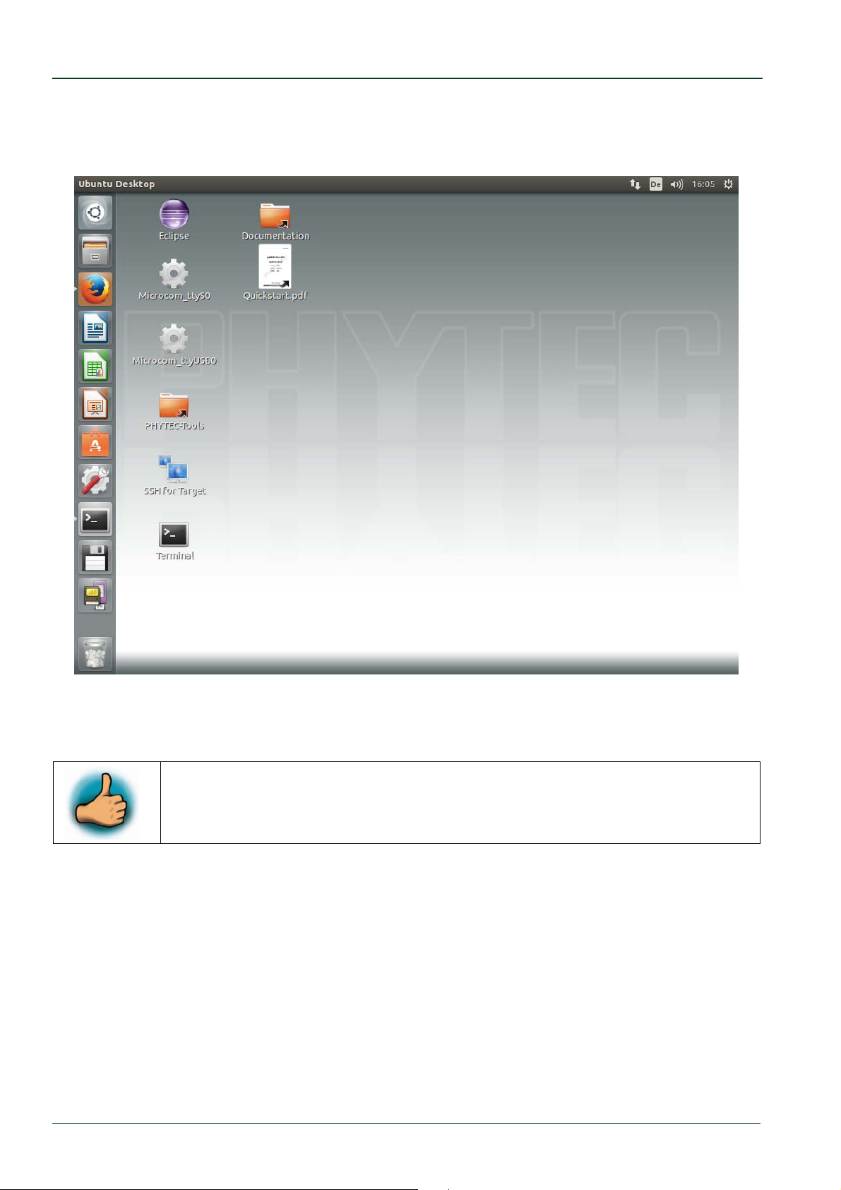
You will see the modified Ubuntu desktop :
For further use of the virtual machine the pre-created login data is:
username: „phyvm“ — password: „phytec“.
Now you are ready to connect your PC with the phyCORE-AM335x.
© PHYTEC Messtechnik GmbH 2016 L-779e_6
6
Page 13
Getting Started
2.2 Starting the Hardware
In this section you will learn how to connect your host PC to the target. The connection will
be done using a cross-over Ethernet cable and a serial one-to-one cable. You will start
Linux from the Flash memory on the target and you will be able to log in with the serial
communication program Microcom as well as via a SSH session using a peer-to-peer
network connection.
By default every input and output is transmitted over the serial
connection with a baud rate of 115200.
Connect the serial cable to the to RS-232 connector X18 (UART0) on the target and the
first serial interface on your host.
Be sure to use the one-to-one serial cable included in this Rapid
Development Kit.
Connect the cross-over Ethernet cable to the Ethernet connector X12 (ETH1) on the
target and to the appropriate network card of your host, which is passed on the virtual
machine.
Click the Microcom_ttyS0 icon on your desktop, if you have connected the target to your
serial interface on your host. If you have connected the serial cable with an USB dongle
to your PC click the Microcom_ttyUSB0 icon on your desktop.
Connect the AC adapter to the power supply connector (+5 V DC) on your board.
After connecting the board to the power supply, the target starts booting and the outputs
will be shown in the
Microcom
terminal while booting. When the target has finished
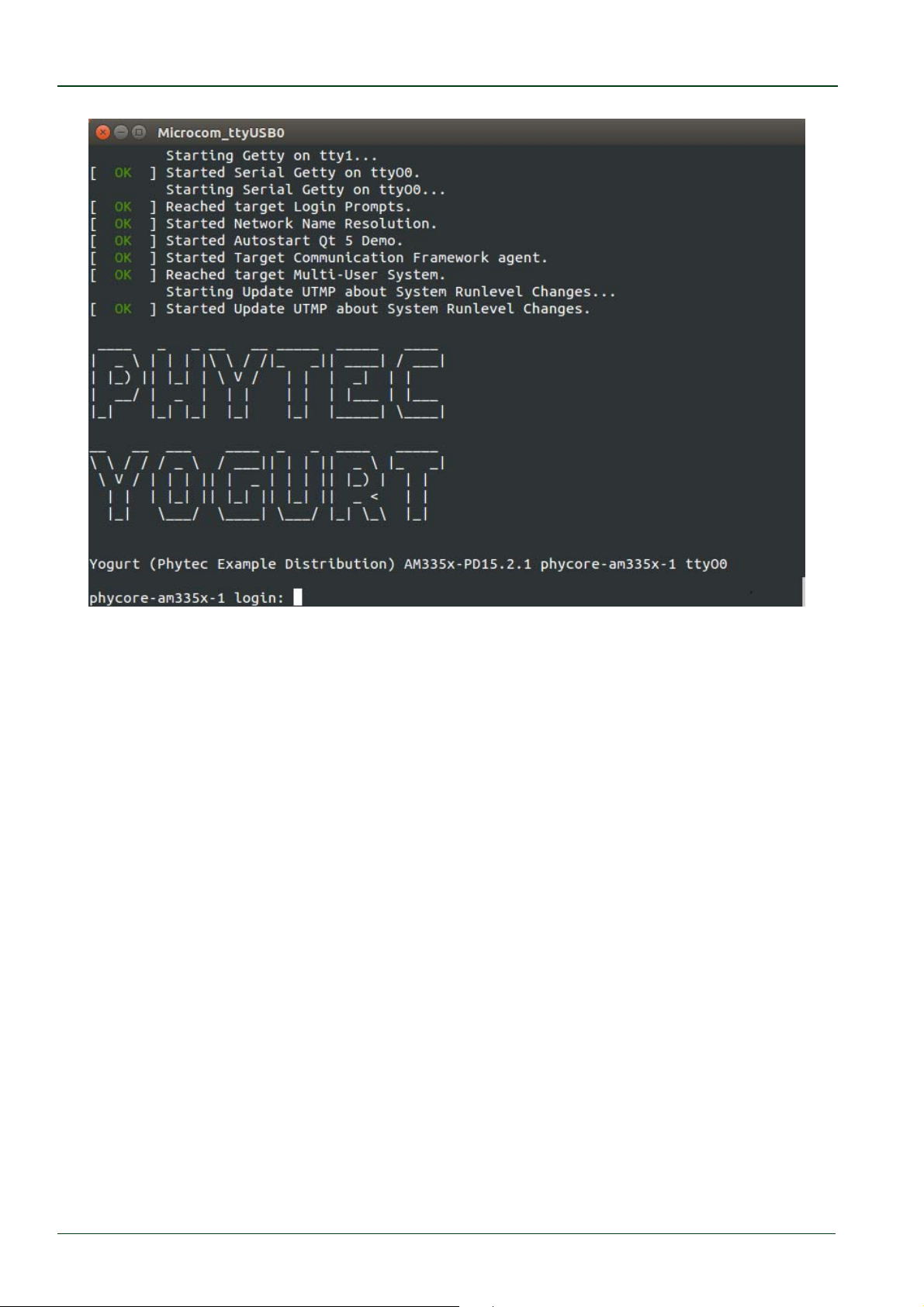
loading the system, you should see a screen similar to the following:
© PHYTEC Messtechnik GmbH 2016 L-779e_6 7
Page 14
phyCORE®-AM335x [PCM-051-xxx]
Enter root as the login name and press
Enter
.
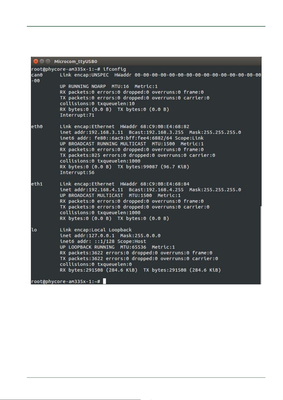
As a good example (and helpful for understanding the next step) enter
ifconfig .
© PHYTEC Messtechnik GmbH 2016 L-779e_6
8
Page 15
Getting Started
You will get information about the configuration of the Ethernet interface on the
phyCORE-AM335x.
© PHYTEC Messtechnik GmbH 2016 L-779e_6 9
Page 16
phyCORE®-AM335x [PCM-051-xxx]
When the target is connected to the power supply, the bootloader
barebox is first loaded from the Flash memory. Next the bootloader is
uncompressing and booting the
kernel will install the root filesystem, which is also located in the target's
Flash.
If you do not see any output in the Microcom window, check the serial
connection between the target and your host. If you have more than one
serial port try the others. By default Microcom uses /dev/ttyS0. If you
want to use another port you can click on the Microcom Icon at your
desktop with your right mouse button and select Properties. A window
opens in which you can change the properties of the Microcom icon. Click
in the Command field and search for "-p /dev/ttyS0". Change it for
example to /dev/ttyS1 and so on if you have more than one serial port.
If you are connecting the board via RS-232 to USB converter change it to
/dev/ttyUSB0. The -p parameter defines the port which Microcom will use.
If the Microcom window does not open, one reason could be a lock-file
which was created when
this file by opening a terminal and type: sudo rm /var/lock/LCK..*
Linux
Microcom
kernel from the Flash. Then the
was not correctly terminated. Delete
In our next step we want to connect to the target via Ethernet, but first we must configure
the Ethernet adapter in our virtual machine.
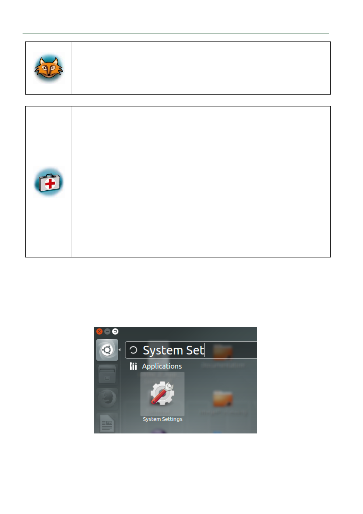
In the Unity-panel (left side of your desktop) click the Dash Home icon.
Enter System Settings in the search field (you will see the corresponding icon showing
up while typing the search string).
© PHYTEC Messtechnik GmbH 2016 L-779e_6
10
Page 17
Getting Started
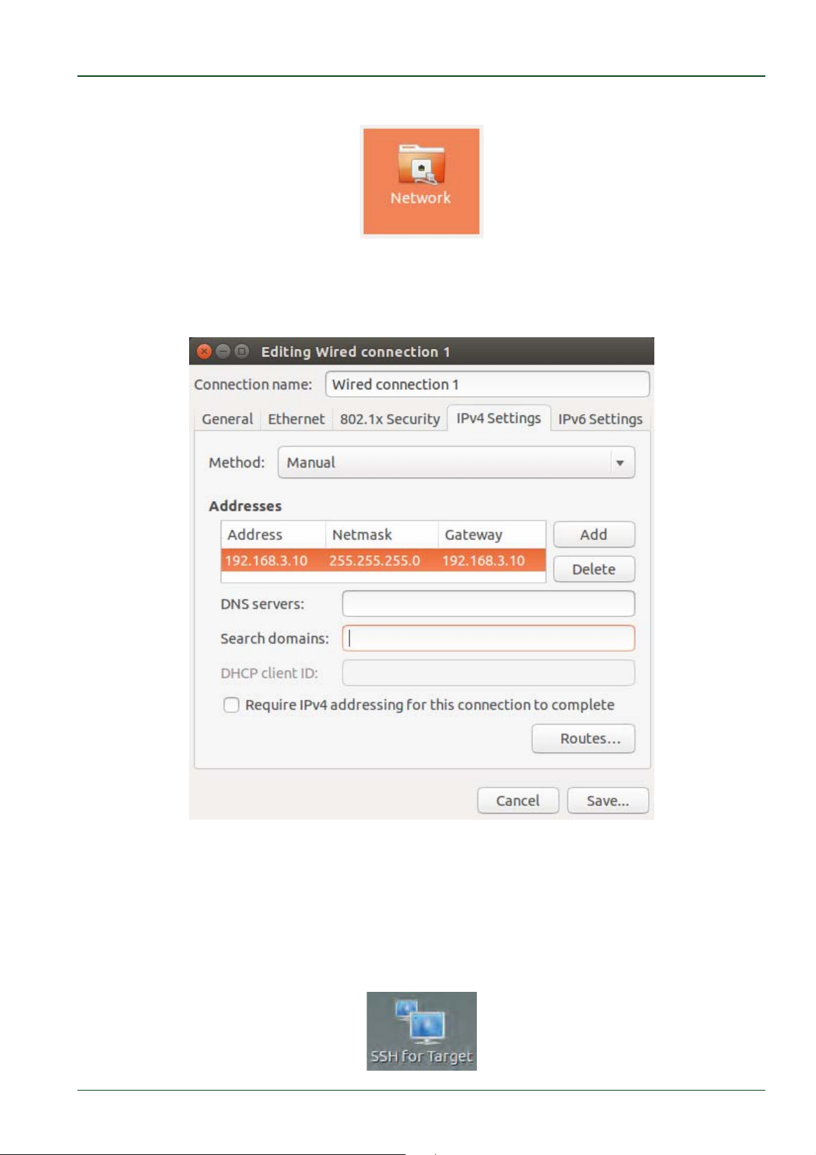
Open System Settings and click the Network icon.
Select the physical interface to which you have connected the Ethernet cable and click
Options.
Select the IPv4 Settings tab and choose Manual in the Method drop down box.
Click Add and enter the IP address
192.168.3.10 as gateway.
192.168.3.10 , 255.255.255.0 as subnet mask and
Finally click Save to save these connection settings and close the windows.
You are now ready to test the Ethernet network connection.
Click the SSH for Target icon on your desktop.
© PHYTEC Messtechnik GmbH 2016 L-779e_6 11
Page 18
phyCORE®-AM335x [PCM-051-xxx]
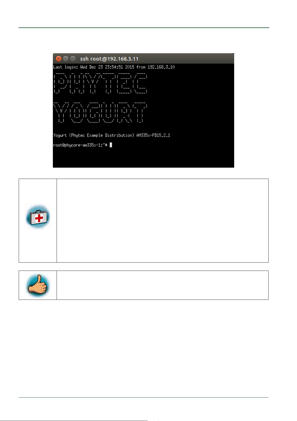
A console window will open and you will see following output in the SSH terminal if the
connection is established successfully:
If you do not see the user login, check the Ethernet connection between
the target and the host. If you have installed more than one network card
on your host, be sure to connect the cable to the network card which you
have configured with the IP address 192.168.3.10.
Be sure that you have configured the network adapter in the virtual
machine configuration as
If you do not see the login, you may not have set up the right IP address
for your host. Open the
NAT
.
System Settings
, click the
Network
icon and
check the settings for the physical interface to which you have connected
the Ethernet cable.
You have successfully set up all configurations to access your
phyCORE-AM335x from your host.
© PHYTEC Messtechnik GmbH 2016 L-779e_6
12
Page 19
Working with Eclipse
3 Working with Eclipse
Now we start developing our own applications with the help of Eclipse.
3.1 Programming in the C/C++ Perspective
We are starting with the C/C++ workbench. Therefore you will import an existing Eclipse
project into your workspace. The imported example project will be compiled with the cross
compiler. After that, you will copy and execute the newly created program on the target.
3.1.1 Work with the Demo Project
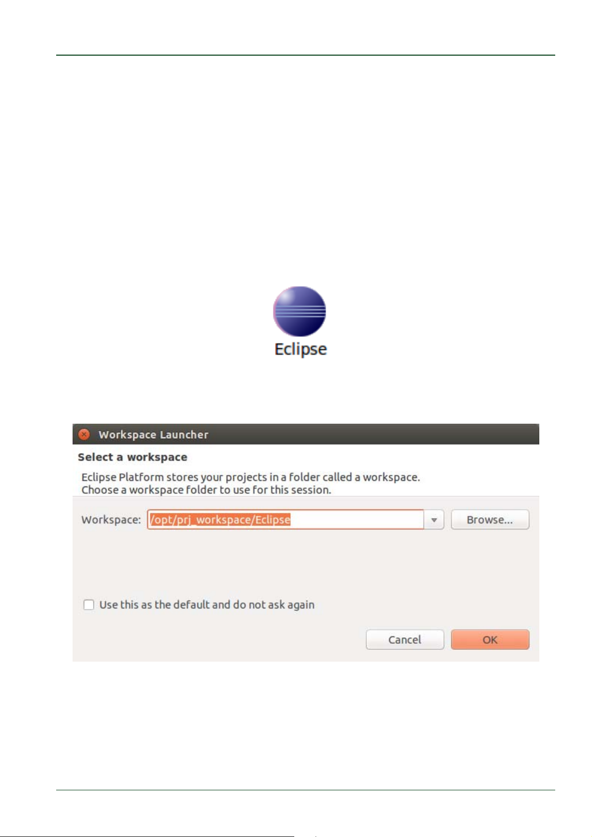
Click the Eclipse icon to start the application. You can find this icon on your desktop.
Change the workspace directory to /opt/prj_workspace/Eclipse if necessary and confirm
with OK.
© PHYTEC Messtechnik GmbH 2016 L-779e_6 13
Page 20
phyCORE®-AM335x [PCM-051-xxx]
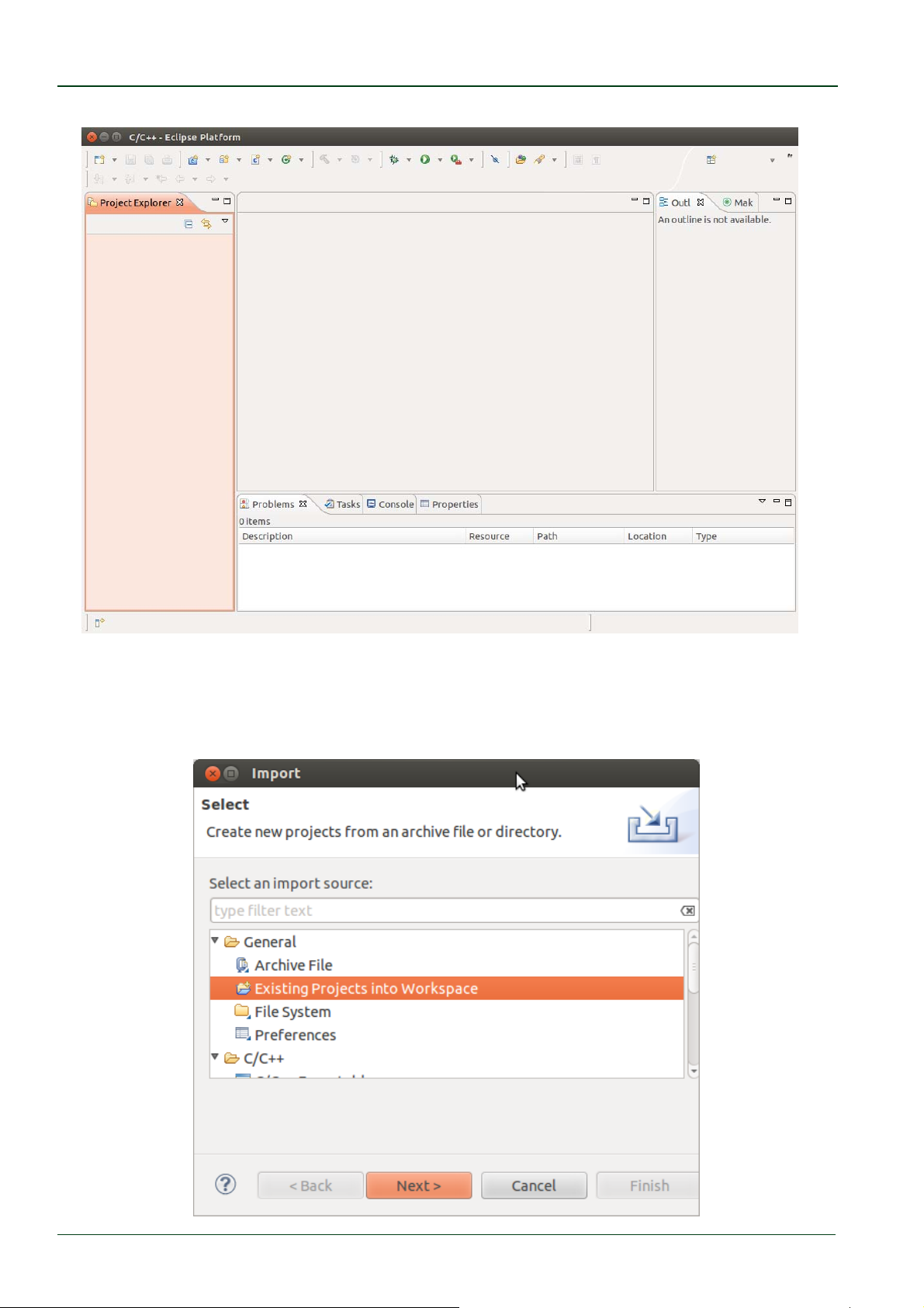
Now you can see the Eclipse workbench.
First we will import an existing project.
Select File ► Import from the menu bar.
Expand General, select Existing Projects into Workspace and click Next.
© PHYTEC Messtechnik GmbH 2016 L-779e_6
14
Page 21
Working with Eclipse
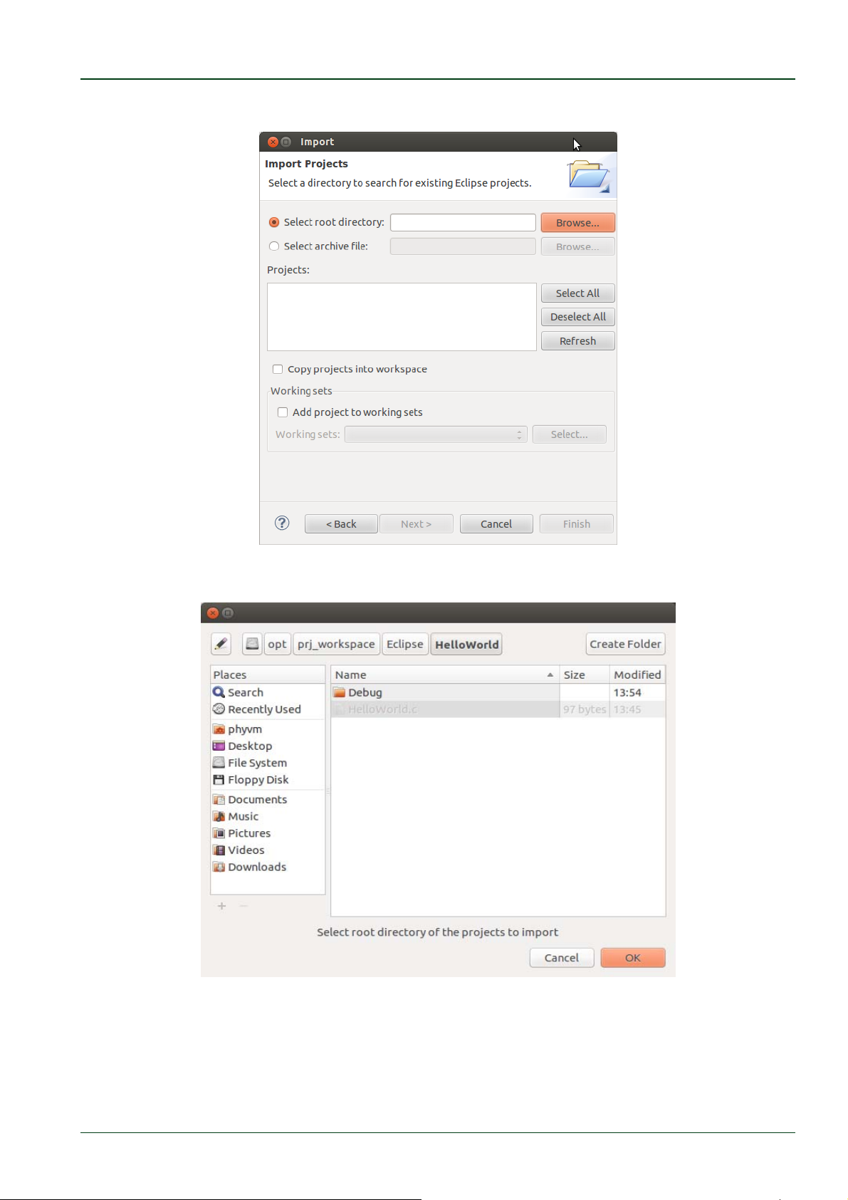
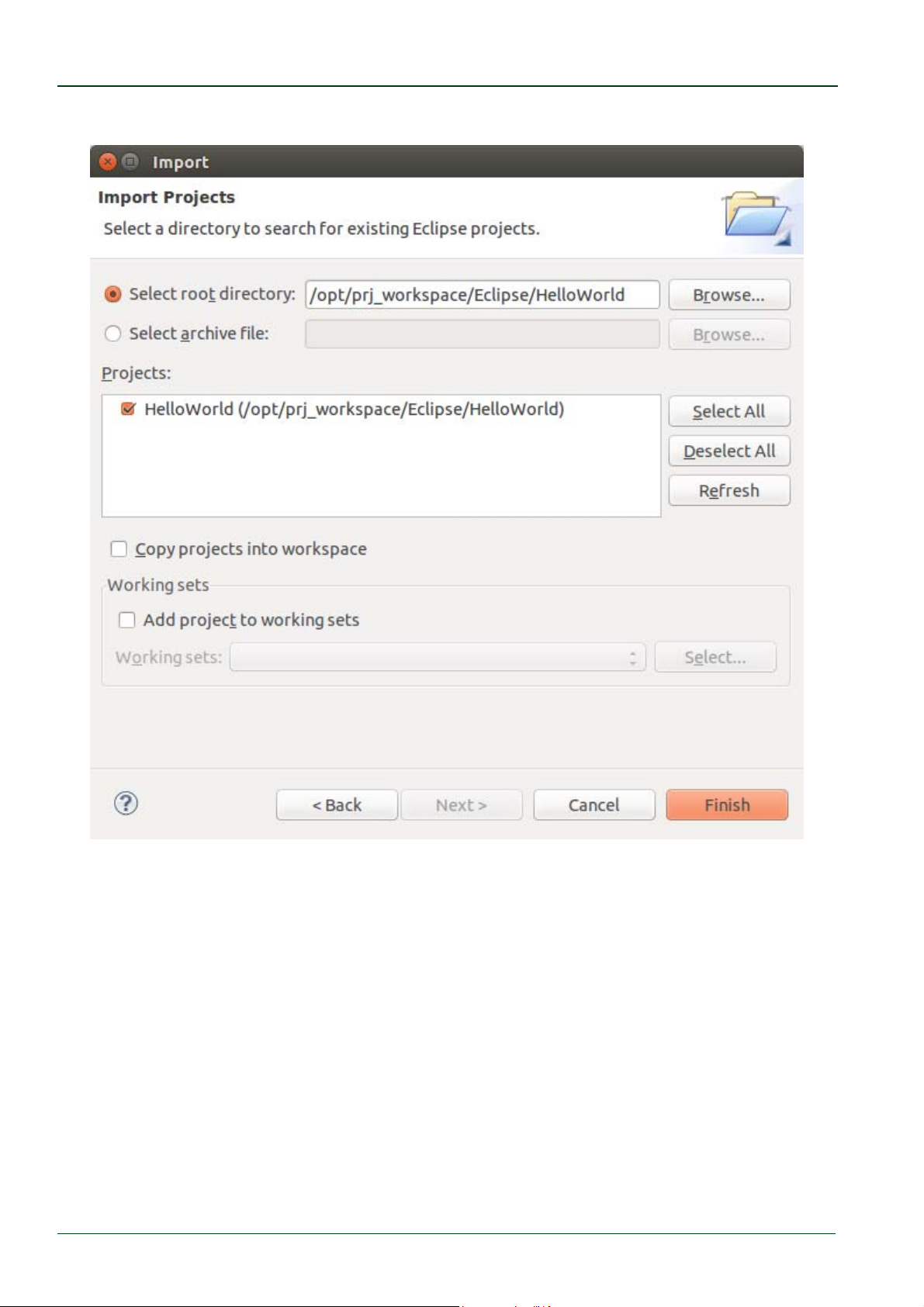
Select Browse.
Double-click the HelloWorld directory under /opt/prj_workspace/Eclipse/.
Click OK.
© PHYTEC Messtechnik GmbH 2016 L-779e_6 15
Page 22
phyCORE®-AM335x [PCM-051-xxx]
Select Finish to import the project.
Select Project ► Build Project from the menu bar.
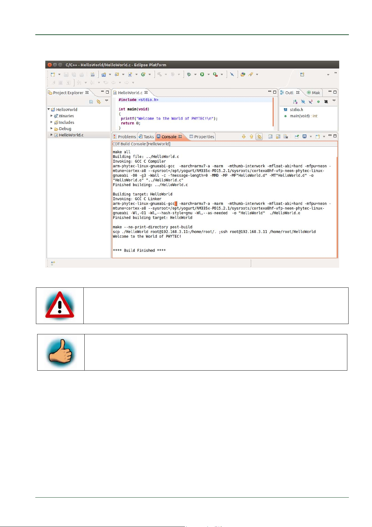
The HelloWorld program will be compiled and the HelloWorld executable is built for the
target. Then the HelloWorld file is copied to the target using secure copy. After the file has
been copied to the target, the program is executed on the target using SSH.
© PHYTEC Messtechnik GmbH 2016 L-779e_6
16
Page 23
Working with Eclipse
You will see the following content in the Console window:
If you do not get this result verify that you have the target connected to
your host, a
QuickStart.
nd that the network has been configured as explained in this
You have successfully passed the first steps with the Eclipse IDE. You are
now able to import existing projects into the Eclipse workspace. Yo
compile an existing project and execute the program on the target.
u can
© PHYTEC Messtechnik GmbH 2016 L-779e_6 17
Page 24
phyCORE®-AM335x [PCM-051-xxx]
3.1.2 Creating a New Project
In this section you will learn how to create a new project with Eclipse and how to configure
the project for use with the GNU C/C++ cross development toolchain.
Open Eclipse if it is not already opened.
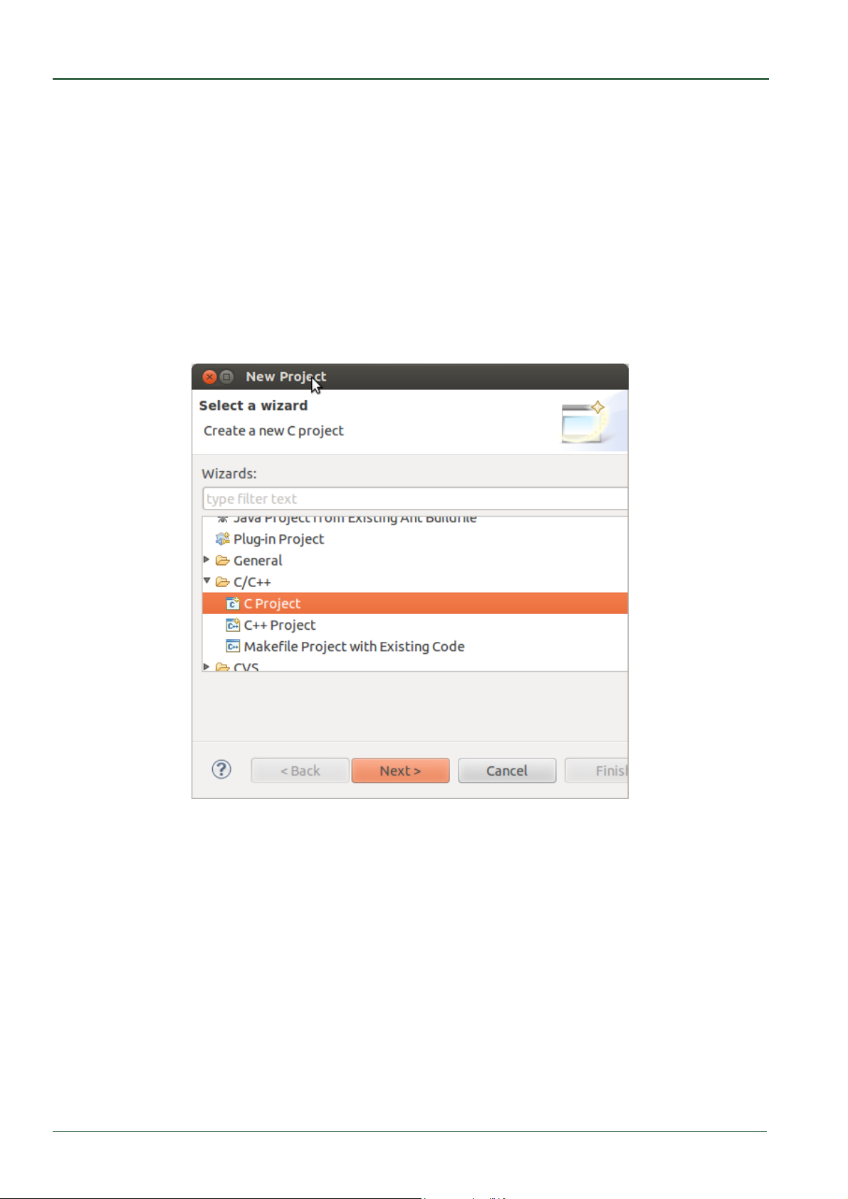
Select File ► New ► Project from the menu bar.
A new dialog opens.
Select C Project and click Next.
© PHYTEC Messtechnik GmbH 2016 L-779e_6
18
Page 25
Working with Eclipse
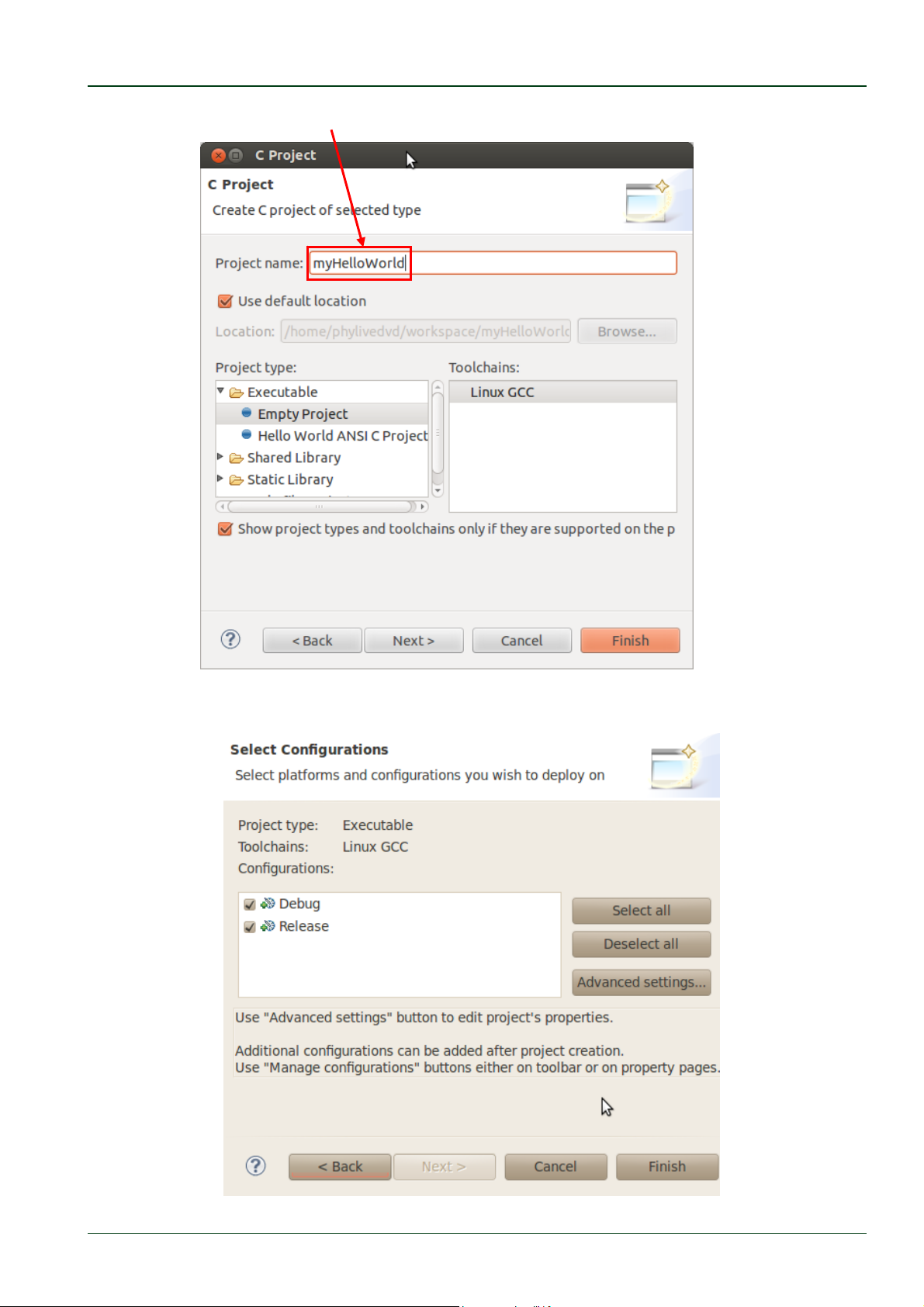
Enter the project name myHelloWorld and click Next.
Click Finish.
© PHYTEC Messtechnik GmbH 2016 L-779e_6 19
Page 26
phyCORE®-AM335x [PCM-051-xxx]
You will see the C/C++ IDE with the myHelloWorld project.
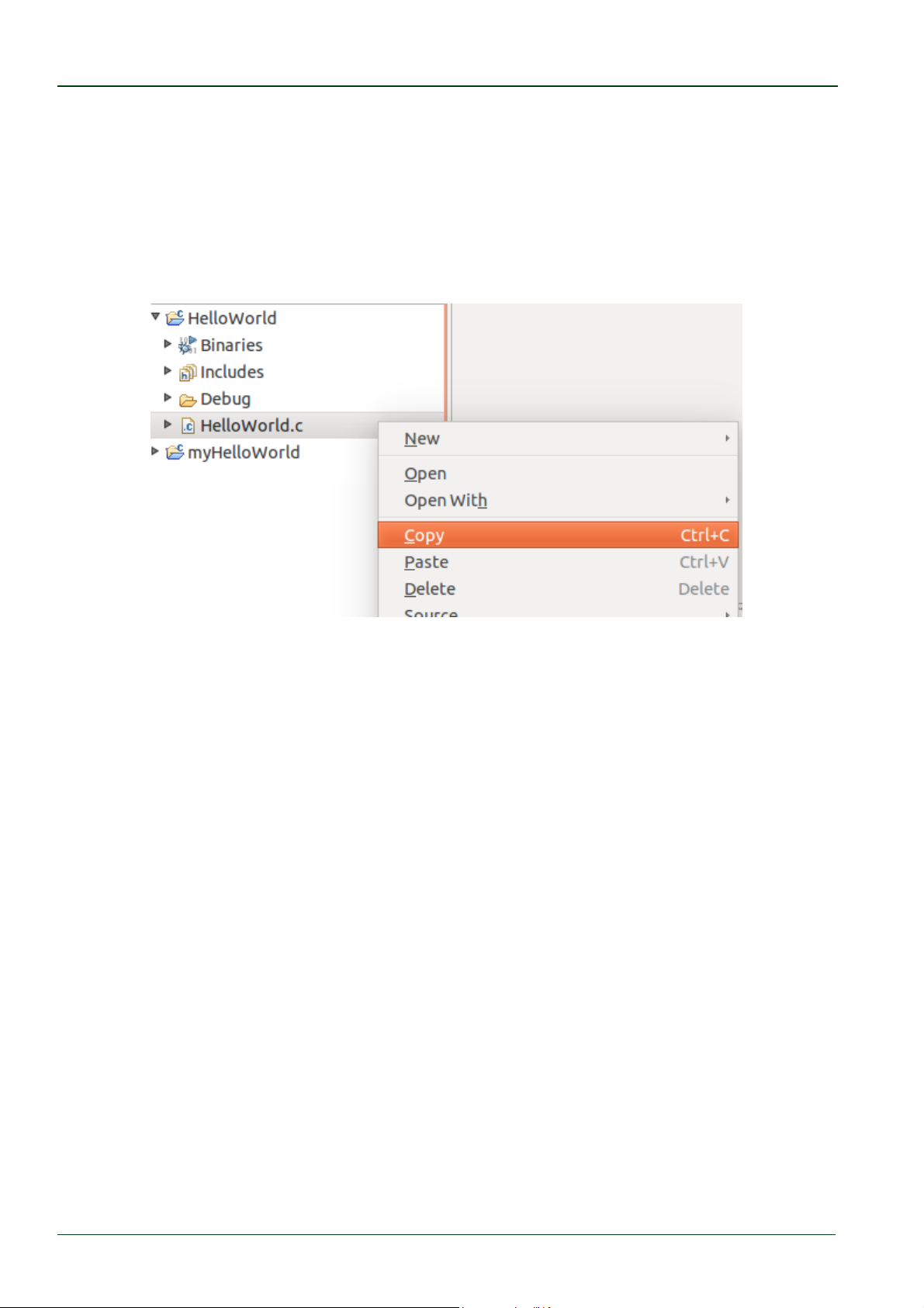
If the HelloWorld project is not expanded double-click the HelloWorld project which we
have worked with previously.
Right-click on HelloWorld.c in the HelloWorld project.
Select Copy.
Select the myHelloWorld project.
Right-click the myHelloWorld project.
Select Paste.
Double-click HelloWorld.c in the myHelloWorld project.
If Build Automatically from the Project menu is selected, the HelloWorld application will now
be compiled and created with the standard GCC C/C++ compiler suitable for your host
machine. You will find the executable file, which can only run on your host system, in the
workspace/myHelloWorld/Debug directory.
To compile your project for phyCORE-AM335x instead, you will have to use the GNU C/C++
cross compiler.
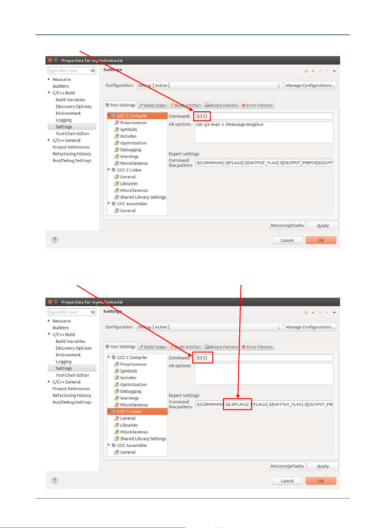
Right-click the myHelloWorld project and choose Properties.
The Properties dialog appears.
Select C/C++ Build ► Settings.
Select GCC C Compiler.
© PHYTEC Messtechnik GmbH 2016 L-779e_6
20
Page 27
Working with Eclipse
Enter
${CC} into the Command input field.
Select GCC C Linker.
Enter
${CC} into the Command input field and add ${LDFLAGS} in the Command line
pattern after ${COMMAND}.
© PHYTEC Messtechnik GmbH 2016 L-779e_6 21
Page 28
phyCORE®-AM335x [PCM-051-xxx]
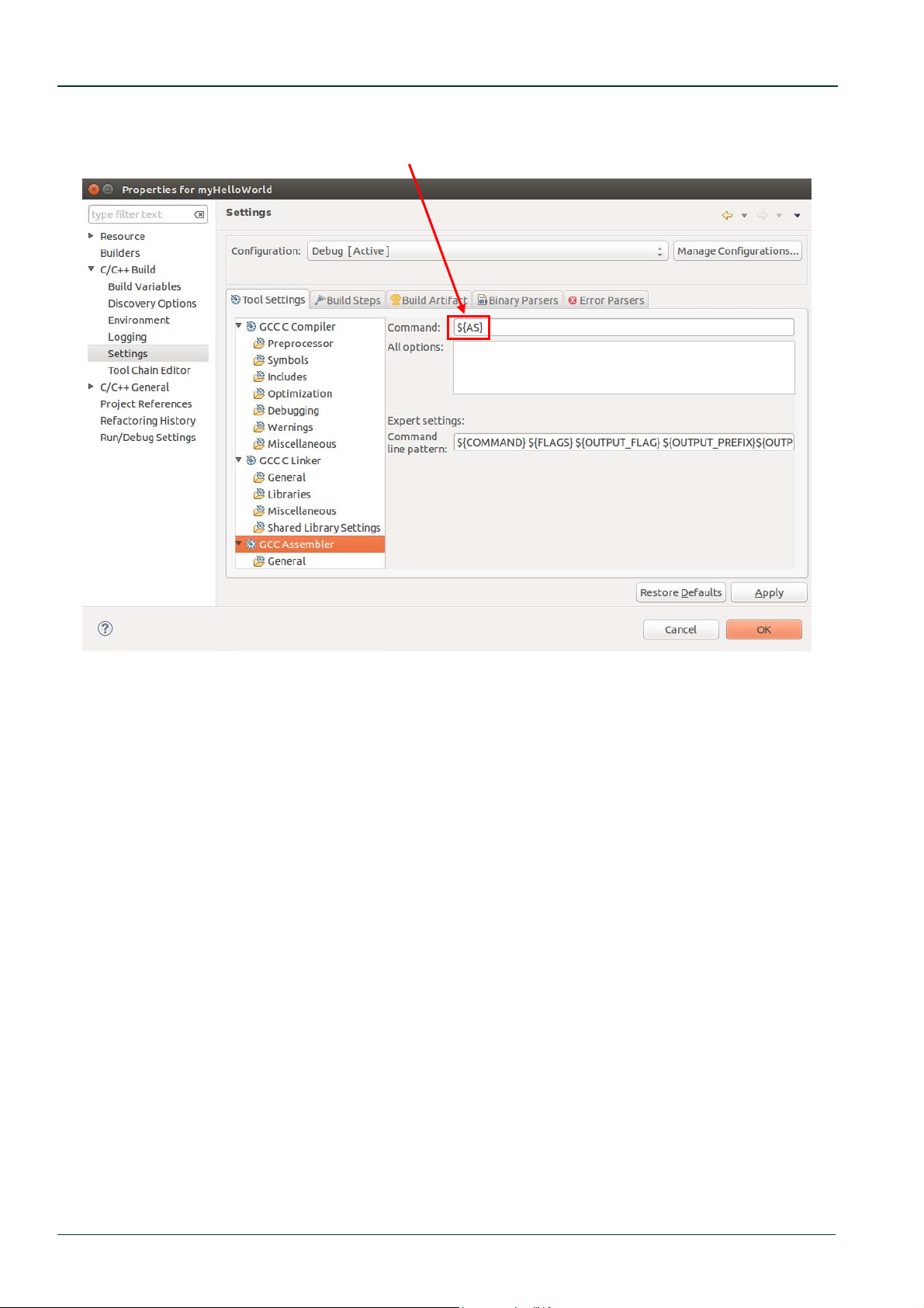
Select GCC Assembler.
Change the Command input field to
${AS}.
Click Apply.
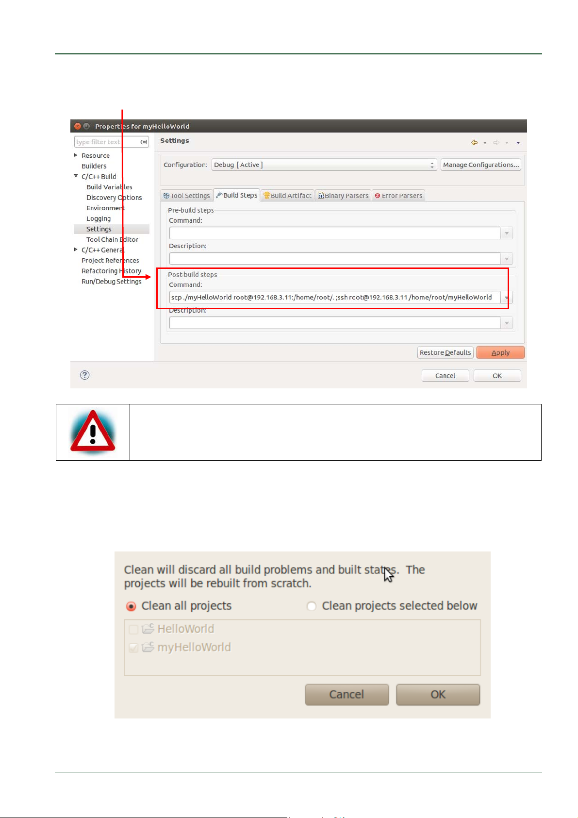
Select the Build Steps tab.
© PHYTEC Messtechnik GmbH 2016 L-779e_6
22
Page 29
Working with Eclipse
Enter the following command in the Post-build steps Command input field:
Be sure to enter the semicolon before the ssh command.
Ensure that the file myHelloWorld on the target will have execution rights,
because otherwise ssh will fail.
Click Apply.
Click OK.
Select Project ► Clean from the menu bar.
Confirm with OK.
© PHYTEC Messtechnik GmbH 2016 L-779e_6 23
Page 30
phyCORE®-AM335x [PCM-051-xxx]
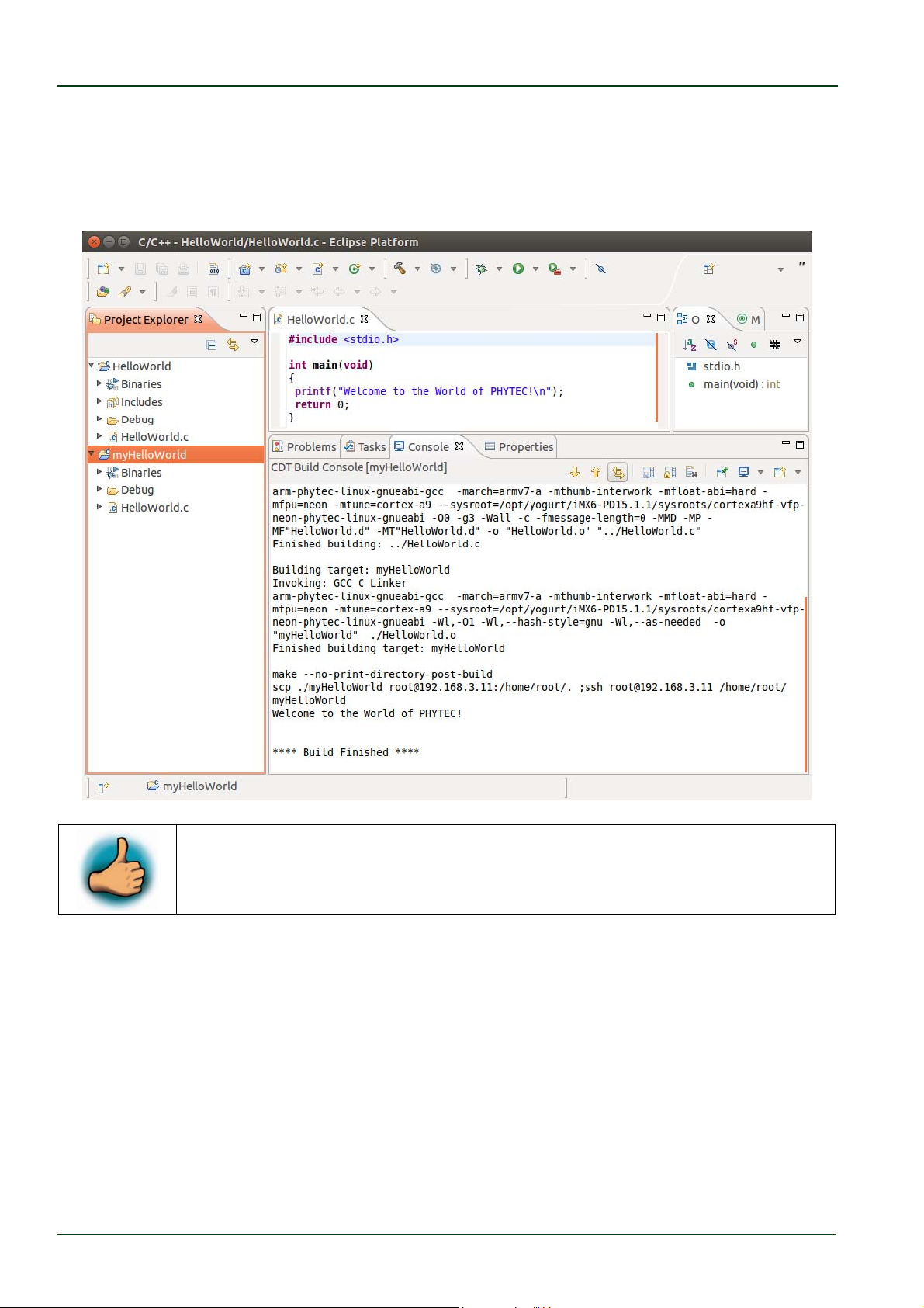
The project will be rebuilt.
Select the Console tab.
If no errors occur while building the project, you will see the following output:
You have successfully created your first own project with the Eclipse IDE.
You have configured the project to create an application for your target
platform.
© PHYTEC Messtechnik GmbH 2016 L-779e_6
24
Page 31
Working with Eclipse
3.1.3 Modifying the Demo Application
Now we will extend the myHelloWorld application. The extended myHelloWorld application
will write an output to the first serial interface as well as to the standard output.
Open Eclipse if it is not opened yet.
Double-click HelloWorld.c in the myHelloWorld project.
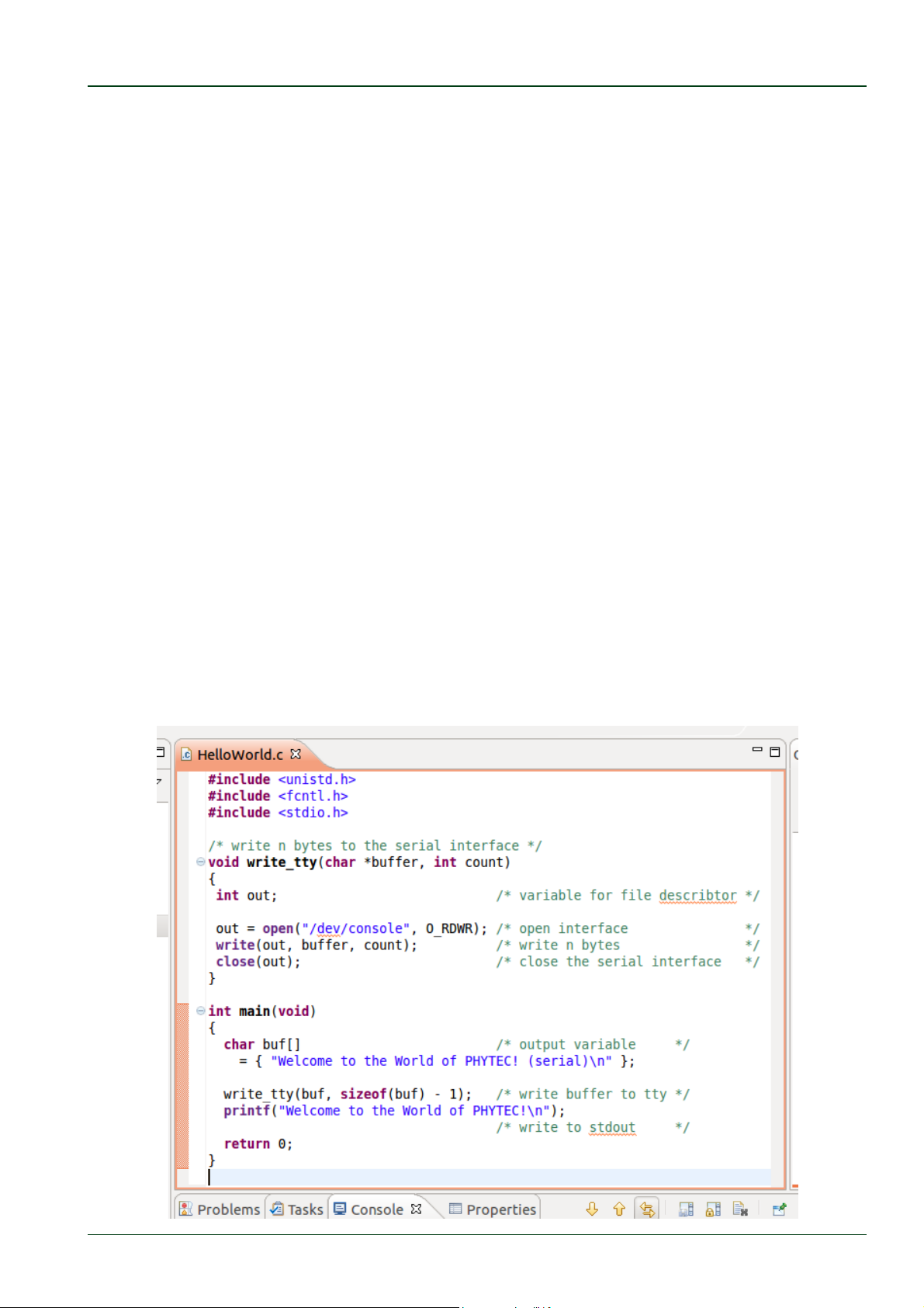
First include the following two additional header files:
#include<unistd.h>
#include<fcntl.h>
Then add the function write_tty(), which writes n bytes to the first serial interface
(which, on the phyCORE-AM335x, is connected to the system console /dev/console):
voidwrite_tty(char*buffer,intcount)
{
intout;
out=open("/dev/console",O_RDWR);
write(out,buffer,count);
close(out);
}
Enter the following two lines in the main() function to declare the buffer and call the
write_tty() function:
charbuf[]={"WelcometotheWorldofPHYTEC!(serial)\n"};
write_tty(buf,sizeof(buf)‐1);
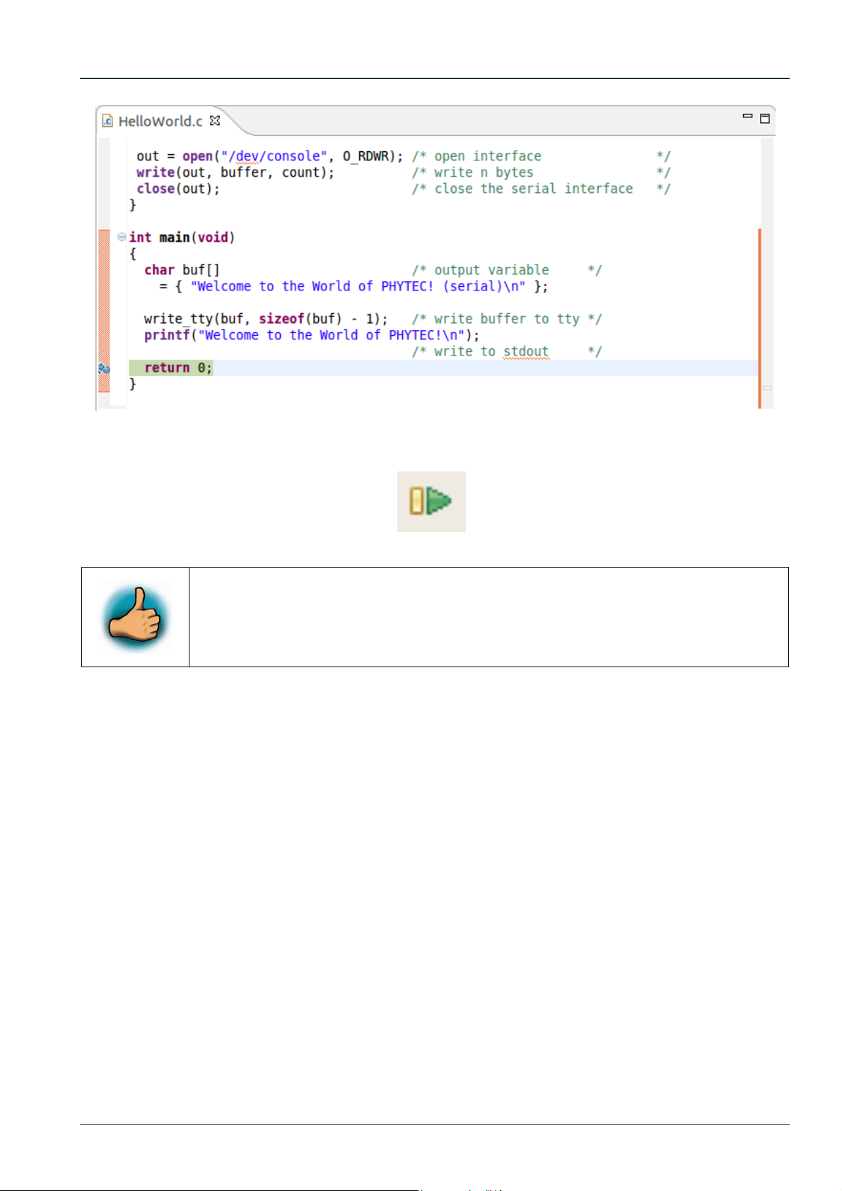
In the next screenshot you can see the complete program.
© PHYTEC Messtechnik GmbH 2016 L-779e_6 25
Page 32
phyCORE®-AM335x [PCM-051-xxx]
Save your program after changing the code.
The application will be compiled, built, copied to the target and executed.
Click the Microcom icon on the desktop.
If you are not logged in, enter
Type .
/myHelloWorld to start the application.
root and press Enter.
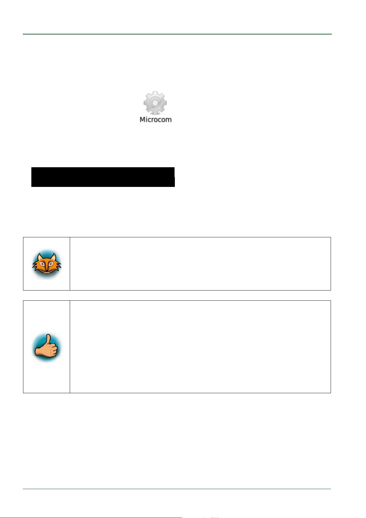
You will see the following output:
.Welcome to the World of PHYTEC! (serial).
.Welcome to the World of PHYTEC!.......... .
Close Microcom.
When you start the application via an SSH session, you only see one output line. When you
execute the program with Microcom, you see two output lines.
The first line is a direct output on the serial interface. You can not see this
line in an SSH session, because you are connected over a TCP/IP
connection to the target. With Microcom, however, you have direct access
to the serial interface, so you can also see the line that is written to the
serial console.
In this section you have changed an existing application. You also
learned how to access the serial interface. First you called the function
open() on the device /dev/console. The return value of this function was a
file descriptor. With the file descriptor you called the function write() to
send n bytes to the device /dev/console. After that, the file descriptor was
closed with the function close().
This procedure is quite typical for Linux, because Linux treats everything
as a file.
© PHYTEC Messtechnik GmbH 2016 L-779e_6
26
Page 33
Working with Eclipse
3.1.4 Starting a Program out of Eclipse on the Target
In the following you will find another method to start an application out of Eclipse.
After compiling a project in Eclipse, the program is copied to the target and directly
executed. A program can also be executed on the target without compiling a project. In the
following section you will learn how to start a program on the target as an external tool.
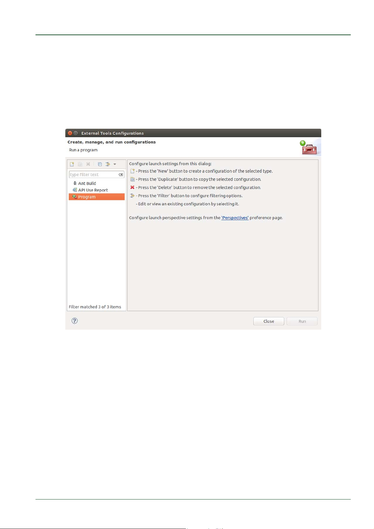
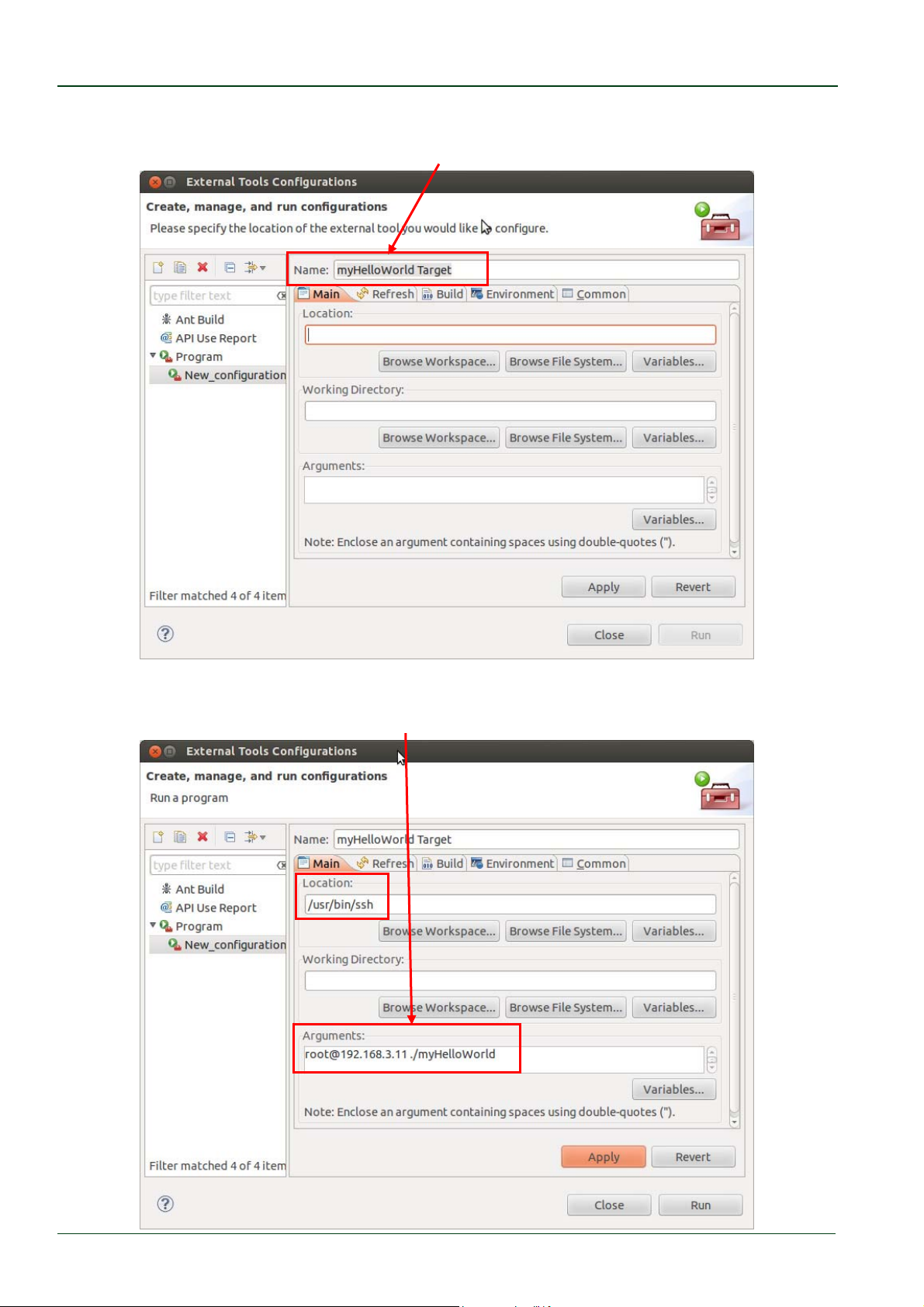
Select Run ► External Tools ► External Tools Configurations from the menu bar.
© PHYTEC Messtechnik GmbH 2016 L-779e_6 27
Page 34
phyCORE®-AM335x [PCM-051-xxx]
Double-click Program a new program configuration will be opened.
In the Name input field, enter:
myHelloWorldTarget.
Enter
Enter
/usr/bin/ssh in the Location input field.
© PHYTEC Messtechnik GmbH 2016 L-779e_6
28
Page 35
Working with Eclipse
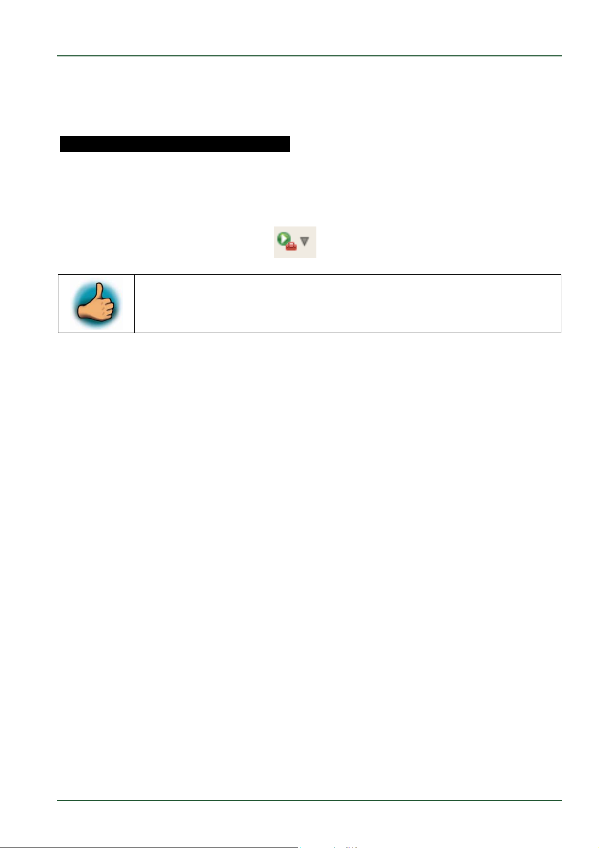
Select Apply.
Select Run.
Now the program is executed on the target and you will see the output
.Welcome to the World of PHYTEC! (serial)
in the Microcom window.
If you want to execute the program the next time, you can use the Run External Programs
button from the menu bar.
You have successfully created your own Eclipse project and you learned
how to execute a program on the target.
3.2 Debugging an Example Project
In this chapter you will learn using the GNU debugger GDB on the host for remote debugging in conjunction with the GDB server on the target. GDB is the symbolic debugger of the
GNU project and is arguably the most important debugging tool for any Linux system.
First you will start the GDB server on the target. Then you will configure the Eclipse
platform and start the GNU debugger out of Eclipse using the Debug view.
The CDT extends the standard Eclipse Debug view with functions for debugging C/C++ code.
The Debug view allows you to manage the debugging and running of a program in the
workbench. Using the Debug view you will be able to set breakpoints/watchpoints in the
code and trace variables and registers. The Debug view displays the stack frame for the
threads of each target you are debugging. Each thread in your program appears as a node
in the tree, and the Debug view displays the process for each target you are running.
The GDB client is running on the host and is used to control the GDB server on the target,
which in turn controls the application running on the target. GDB client and GDB server can
communicate over a TCP/IP network connection as well as via a serial interface. In this
QuickStart we will only describe debugging via TCP/IP.
© PHYTEC Messtechnik GmbH 2016 L-779e_6 29
Page 36

phyCORE®-AM335x [PCM-051-xxx]
3.2.1 Starting the GDB Server on the Target
In this passage you will learn how to start the GDB server on the target. The GDB server will
be used to start and control the myHelloWorld program.
To debug a program with GDB, the program needs extended debugging symbols. These
have already been added while building the program.
Open Microcom.
Type
rootand press Enter.
Start the GDB server:
gdbserver192.168.3.11:10000myHelloWorld
You have started the GDB server on the target. The GDB server is now waiting for
connections on TCP port 10000.
3.2.2 Configuring and Starting the Debugger in Eclipse
In this passage you will learn how to configure your project settings to use Eclipse with the
GNU debugger. After the configuration of your project settings, the GNU debugger will start
and connect to the GDB server on the target.
Start Eclipse if the application is not started yet.
Right-click on the myHelloWorld project in the Navigator window.
Select Debug As ► Debug Configurations.
A dialog to create, manage and run applications appears.
© PHYTEC Messtechnik GmbH 2016 L-779e_6
30
Page 37
Working with Eclipse
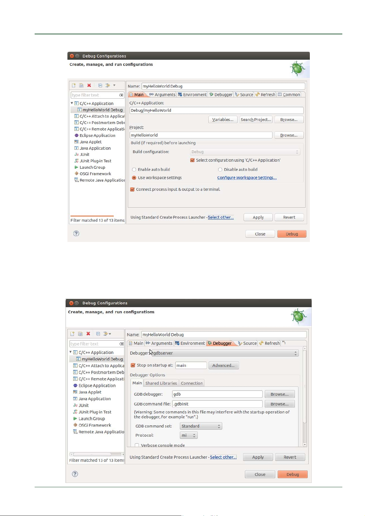
Select myHelloWorld under C/C++ Application (to expand it double-click on it).
Make sure that the Standard Create Process Launcher is used (as shown in the bottom of
the window, left from the Apply button). Otherwise click Select other… and select the
above named launcher.
Select the Debugger tab.
© PHYTEC Messtechnik GmbH 2016 L-779e_6 31
Page 38
phyCORE®-AM335x [PCM-051-xxx]
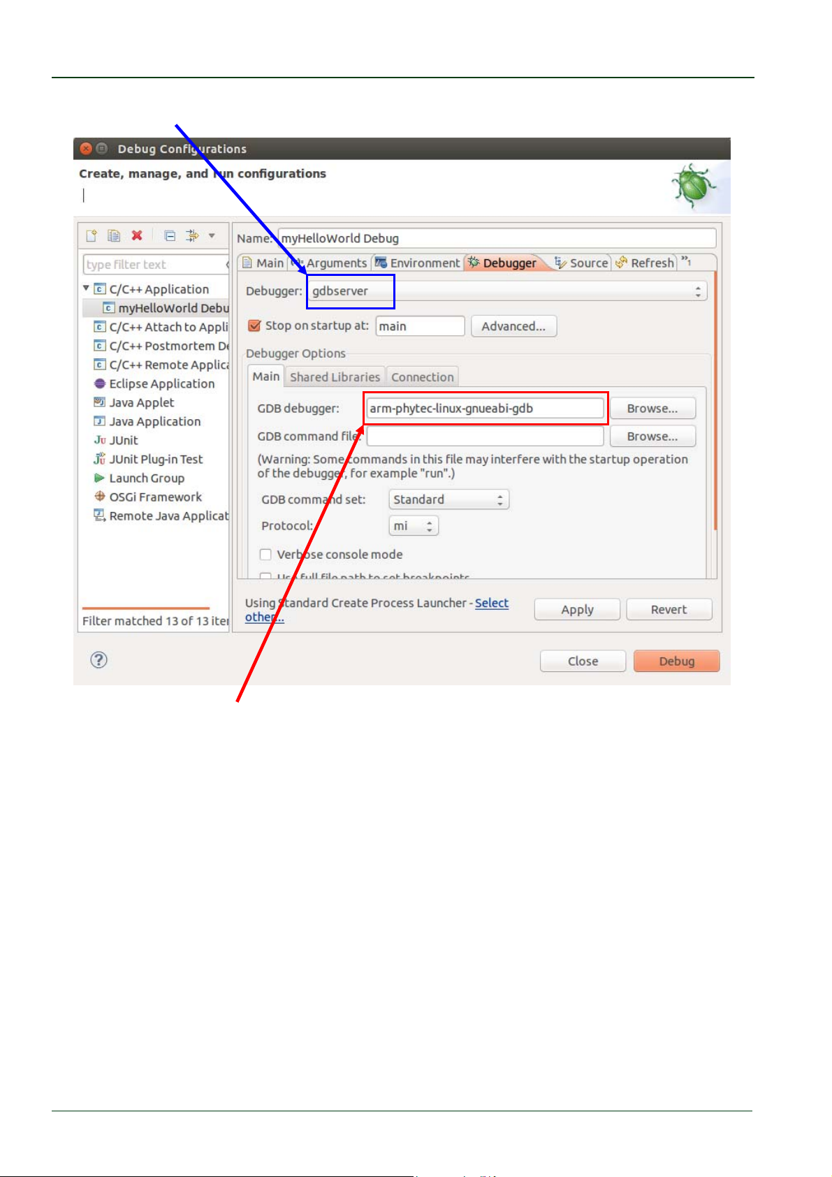
Select gdbserver Debugger from the Debugger drop-down box.
Enter arm‐phytec‐linux‐gnueabi‐gdb in the GDB Debugger field
Keep the GDB command file field empty.
© PHYTEC Messtechnik GmbH 2016 L-779e_6
32
Page 39
Working with Eclipse
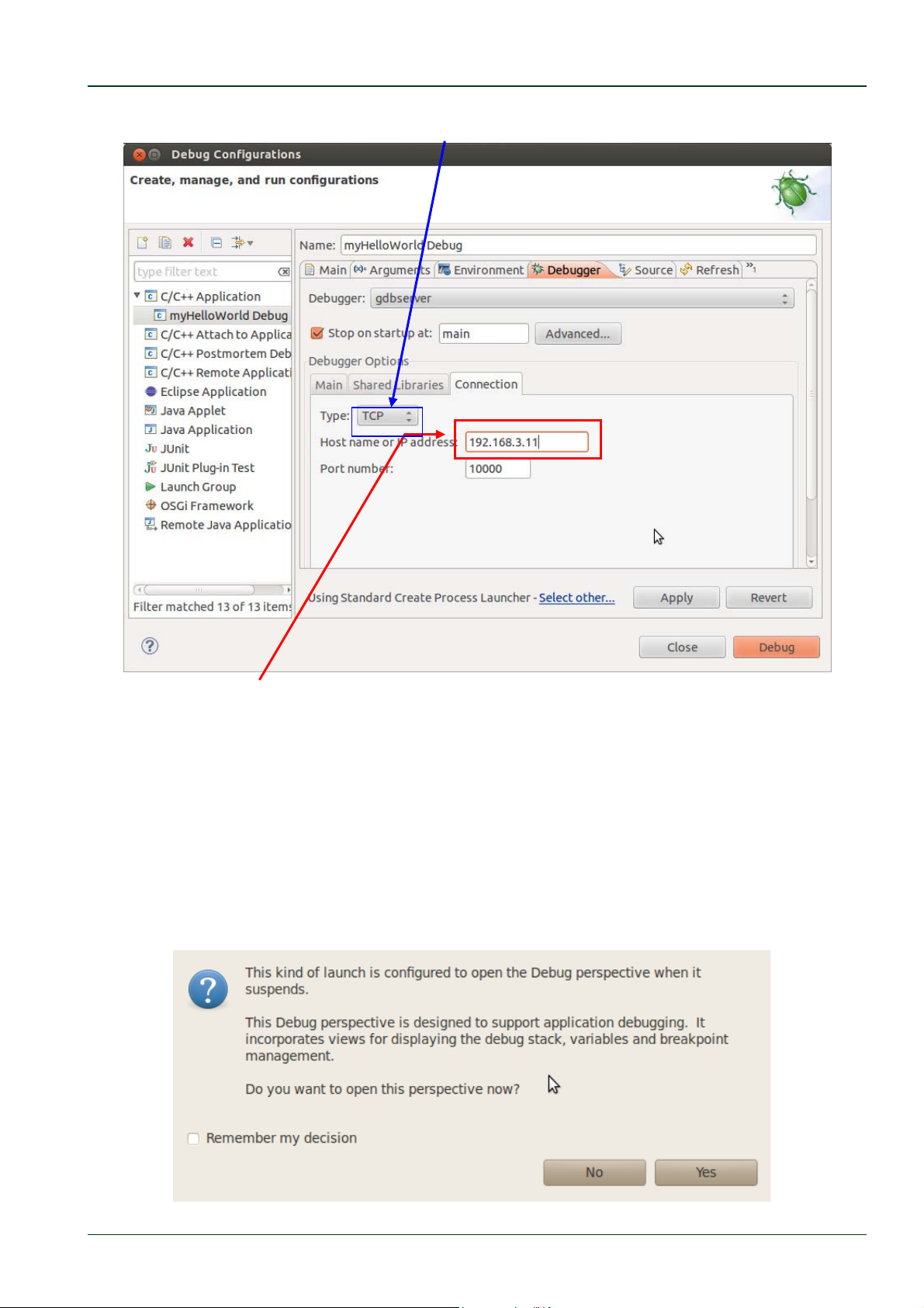
Select the Connection tab and select TCP in the drop-down box.
Enter
192.168.3.11 (the target's IP address) in the Host name input field.
The host's GDB will connect to this IP address to communicate with the target's GDB server.
Click Apply.
Click Debug.
A new dialog appears.
Select Yes to switch to the Debug perspective.
© PHYTEC Messtechnik GmbH 2016 L-779e_6 33
Page 40
phyCORE®-AM335x [PCM-051-xxx]
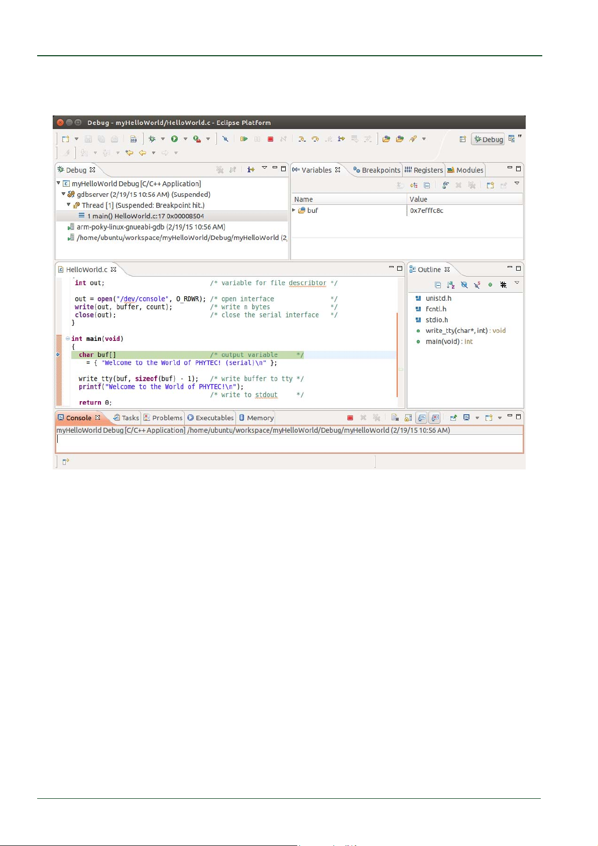
The debug perspective opens and the debugger stops automatically at the first line. The
host's GDB is now connected to the GDB server on the target.
You have configured your project for remote debugging. You have started the GNU
debugger in Eclipse and connected the host's GDB with the target's GDB server. You can
now start to debug the project.
© PHYTEC Messtechnik GmbH 2016 L-779e_6
34
Page 41
Working with Eclipse
3.2.3 Setting a Breakpoint
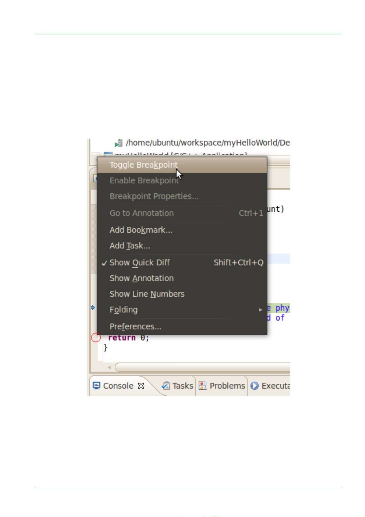
Now you will set a breakpoint in your program. The breakpoint will be set on the last line of
the function main(). If you resume the application, the debugger will stop at this line.
Select the last line in main().
Right-click into the small grey border on the left-hand side and select
Toggle Breakpoint to set a new breakpoint.
© PHYTEC Messtechnik GmbH 2016 L-779e_6 35
Page 42
phyCORE®-AM335x [PCM-051-xxx]
3.2.4 Stepping through and Watching Variable Contents
In this part you will step through the example project with the debugger. You will also
learn how to check the content of a variable.
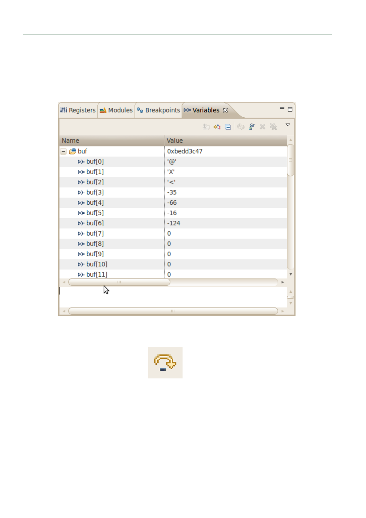
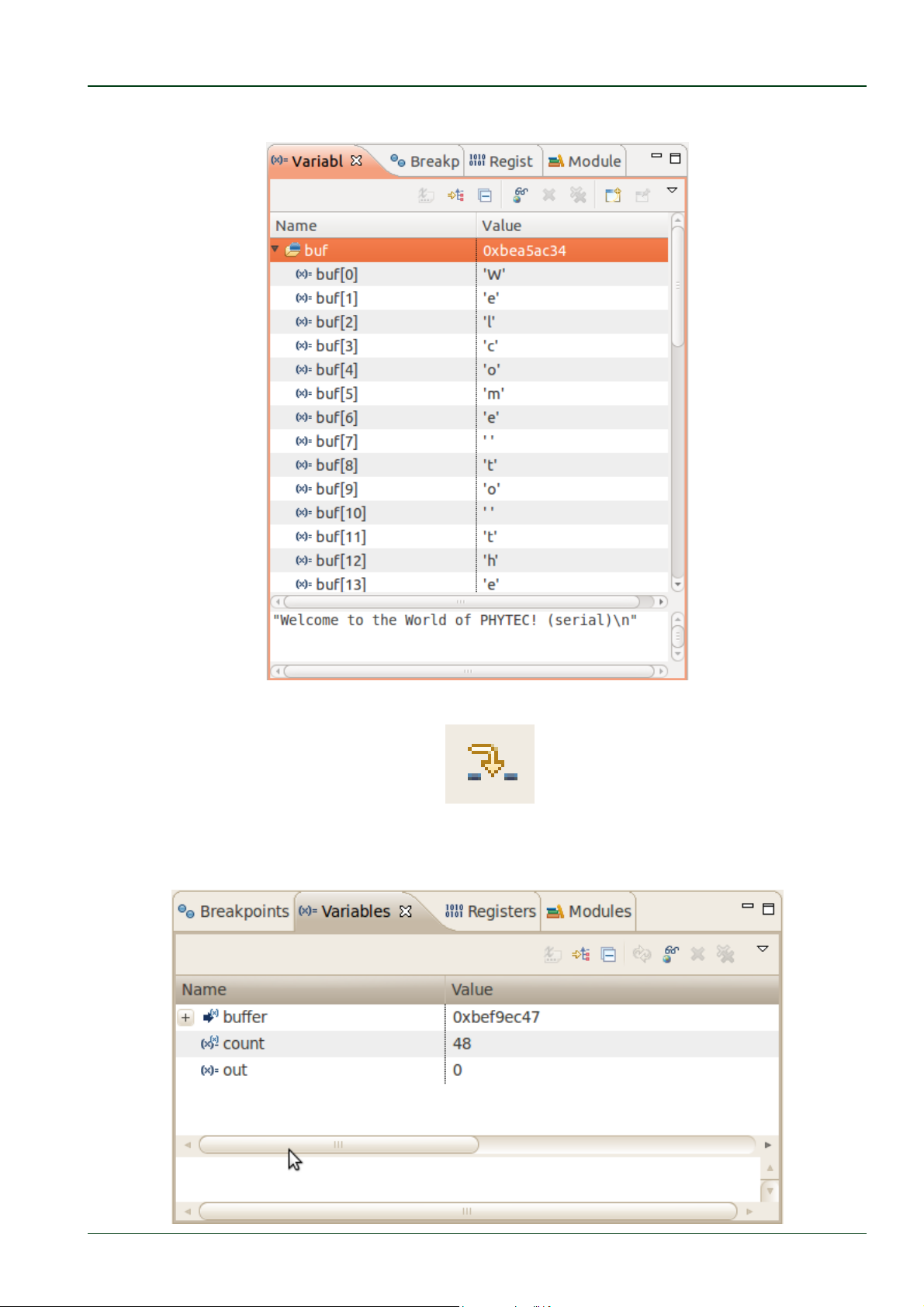
Expand buf in the Variables window.
Click the Step Over button in the Debug window to step to the next line. You will see the
content of the buf variable in the Variables window.
© PHYTEC Messtechnik GmbH 2016 L-779e_6
36
Page 43
Working with Eclipse
Click on the variable buf.
Then click the button Step into to enter the function write_tty().
The debugger stops in write_tty().
You will see the following variable window:
© PHYTEC Messtechnik GmbH 2016 L-779e_6 37
Page 44
phyCORE®-AM335x [PCM-051-xxx]
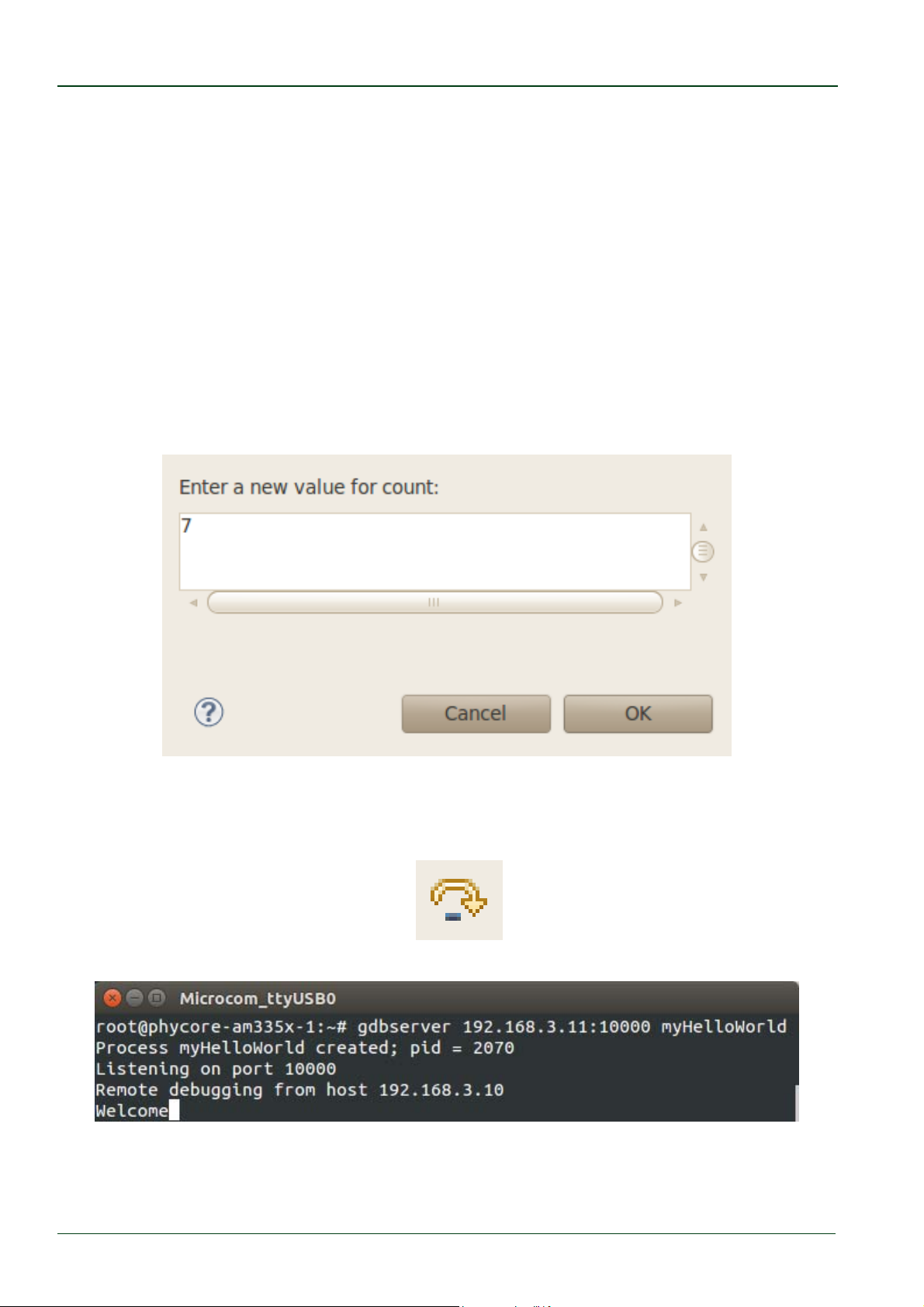
Click on the variable buffer.
You will probably see a different address on the buffer pointer. Remember which address is
shown in your case, you will need this address later.
3.2.5 Stepping through and Changing Variable Contents
In this section you will change the value of a variable. At the end of this part you will see
the effect of this change.
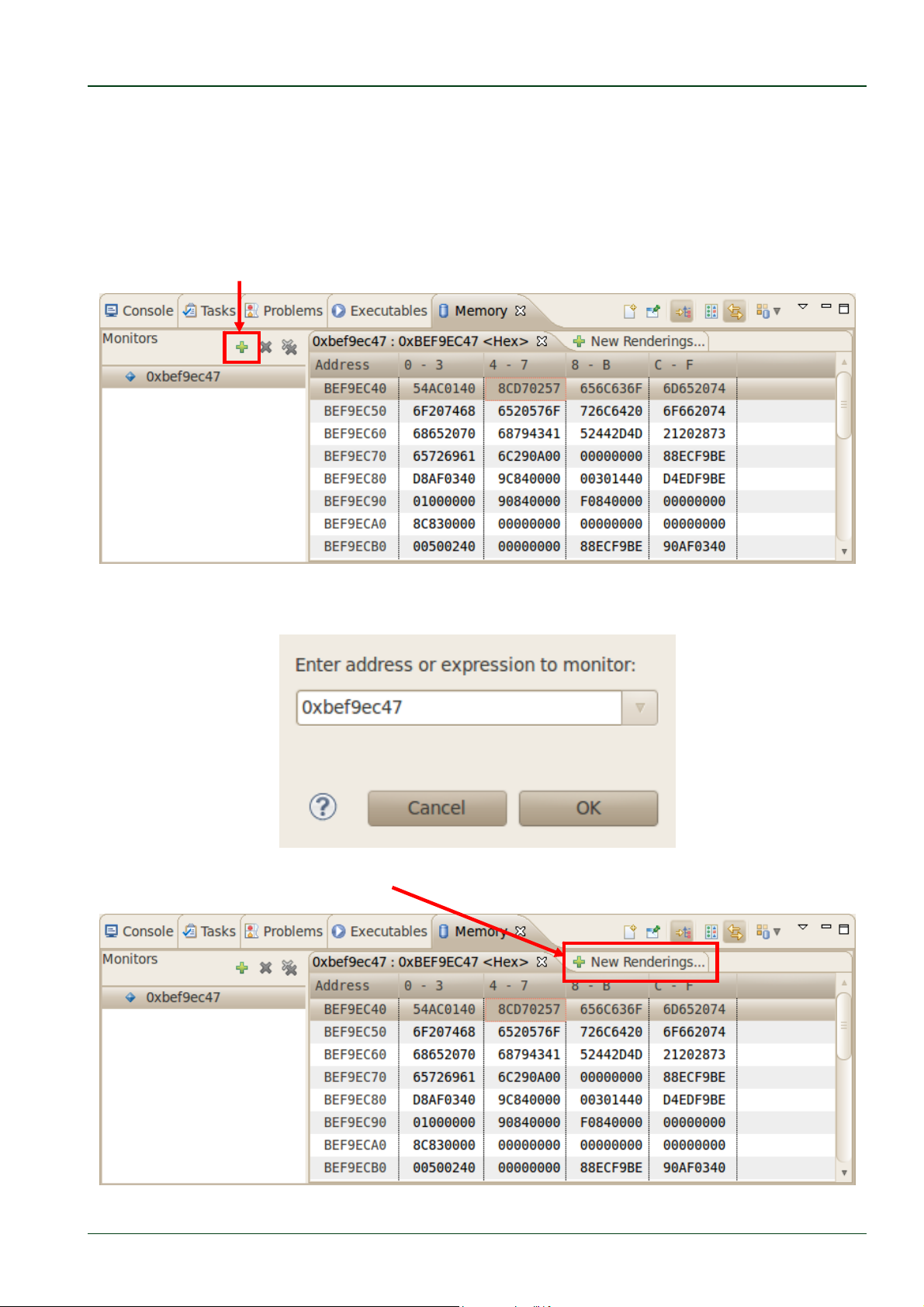
Select the count variable in the Variables window.
Right-click on count and select Change Value.
Change the value of count to
7 and click OK.
Open Microcom if the application is not already opened.
Go back to Eclipse.
Click the Step Over button twice.
Switch to Microcom.
Because we changed the count variable to 7 only the first seven characters (Welcome) are
displayed in the Microcom console.
© PHYTEC Messtechnik GmbH 2016 L-779e_6
38
Page 45
Working with Eclipse
3.2.6 Using the Memory Monitor
In the last section of this chapter you will use the memory monitor to control the content
at a memory address.
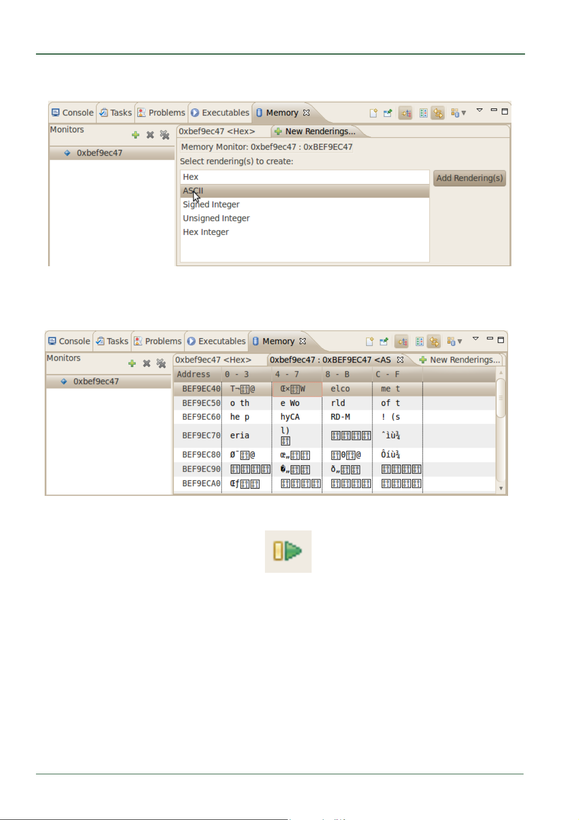
Select the Memory tab in the frame where you can find the Console.
Click + Add Memory Monitor.
Enter the address of the buffer and click OK. Remember that the variable's address
might be different on your system.
Select the tab + New Renderings.
© PHYTEC Messtechnik GmbH 2016 L-779e_6 39
Page 46
phyCORE®-AM335x [PCM-051-xxx]
Select ASCII and click Add Rendering(s).
You can see the contents of th
ddress used on your system).
a
e variable buffer at address 0xbef9ec47 (or at the specific
Now click the Resume button from the menu bar.
The debugger stops at the breakpoint in the last line of main().
© PHYTEC Messtechnik GmbH 2016 L-779e_6
40
Page 47
Working with Eclipse
Click the Resume button to end the application.
You have successfully passed the debugging chapter. You are now able to
configure and use Eclipse for remote debugging. You can step through a
project, watch and change the content of variables, and you can use the
memory monitor to view the content at a memory address.
© PHYTEC Messtechnik GmbH 2016 L-779e_6 41
Page 48

phyCORE®-AM335x [PCM-051-xxx]
© PHYTEC Messtechnik GmbH 2016 L-779e_6
42
Page 49
Working with Qt Creator
4 Working with Qt Creator
In this section we learn how to work with Qt Creator. The Qt framework provides tools to
develop graphical user interfaces. With the help of an example project we show how to
compile your own Qt-based programs and automatically transfer them to the target.
Qt, provided by The Qt Company a subsidiary of Digia Plc., is very
commonly used for embedded systems and it is supported by this BSP.
Please visit http://www.qt.io in order to get all the documentation that is
available about this powerful cross-platform GUI toolkit.
Some demos that show the capabilities of Qt version 5.4.3 are included in
the BSP.
4.1 Stop the Running Qt Demo on the Target
A Qt demo application starts automatically by default after the target has booted
completely. Before we start compiling and running our example project out of Qt Creator we
must first close this Qt application.
Open a serial connection with Microcom.
After the target is booted login with root and enter the following command to stop the
Qt application:
systemctlstopphytec‐qtdemo
After the Qt demo is stopped with the command above we can start to use Qt Creator.
If you want to remove the phytec-qtdemo from the autostart enter the
following command:
systemctldisablephytec‐qtdemo
© PHYTEC Messtechnik GmbH 2016 L-779e_6 43
Page 50
phyCORE®-AM335x [PCM-051-xxx]
4.2 Importing the Demo Application
We start with opening the Qt Creator in a terminal, because otherwise the correct
environment of the toolchain is not set.
Open a terminal.
Enter the following command in the terminal to start Qt Creator
/usr/bin/qtcreator.sh&
Be sure to start Qt Creator in a terminal. Otherwise paths to the correct
toolchain will be missing.
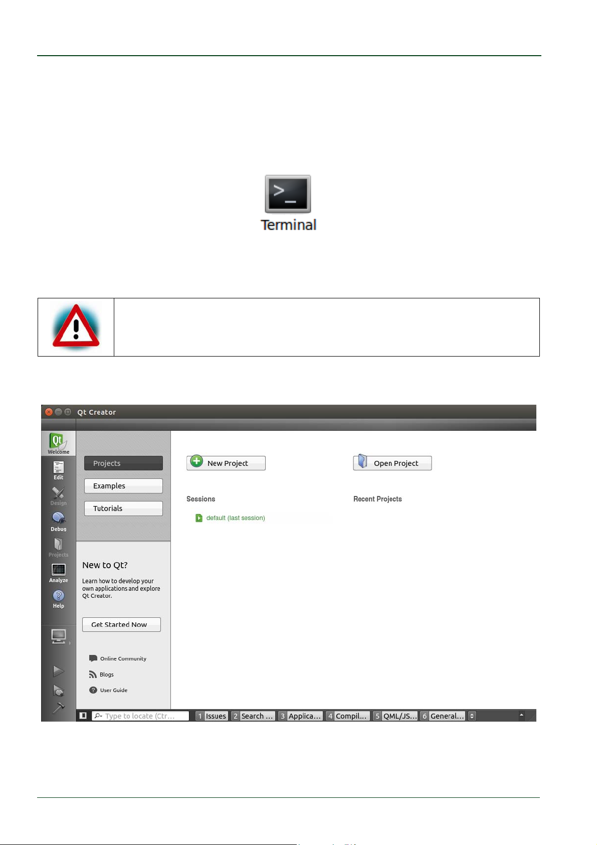
The user interface of Qt Creator appears:
Now we import the example project by clicking Open Project.
© PHYTEC Messtechnik GmbH 2016 L-779e_6
44
Page 51
Working with Qt Creator
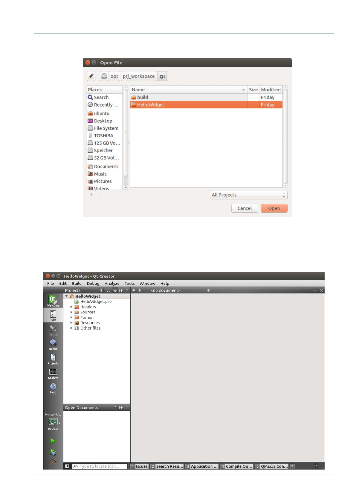
This opens a dialog in which the path to /opt/prj_workspace/Qt is set automatically.
Double-click the HelloWidget folder.
Select HelloWidget.pro and click Open.
The HelloWidget project is now imported into your Qt Creator workspace.
© PHYTEC Messtechnik GmbH 2016 L-779e_6 45
Page 52
phyCORE®-AM335x [PCM-051-xxx]
4.3 Work with the Demo Application
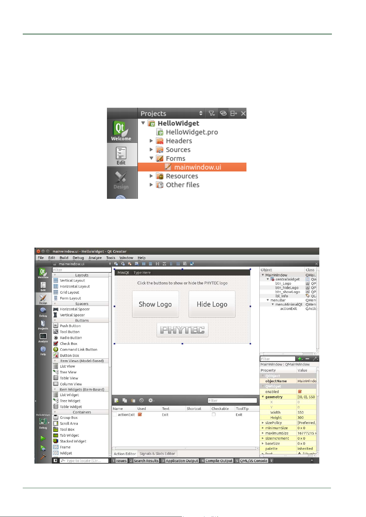
Our example project is a simple Qt Widget Application. First we take a look at the user
interface of our example:
Expand the folder Forms under the project sidebar on the left side and double-click
mainwindow.ui.
Qt Creator opens the design mode and you can see the design of our project, which has a
menu bar with an exit action under the menu item miniQT, one label and three buttons
including one with the Phytec logo inside.
© PHYTEC Messtechnik GmbH 2016 L-779e_6
46
Page 53
Working with Qt Creator
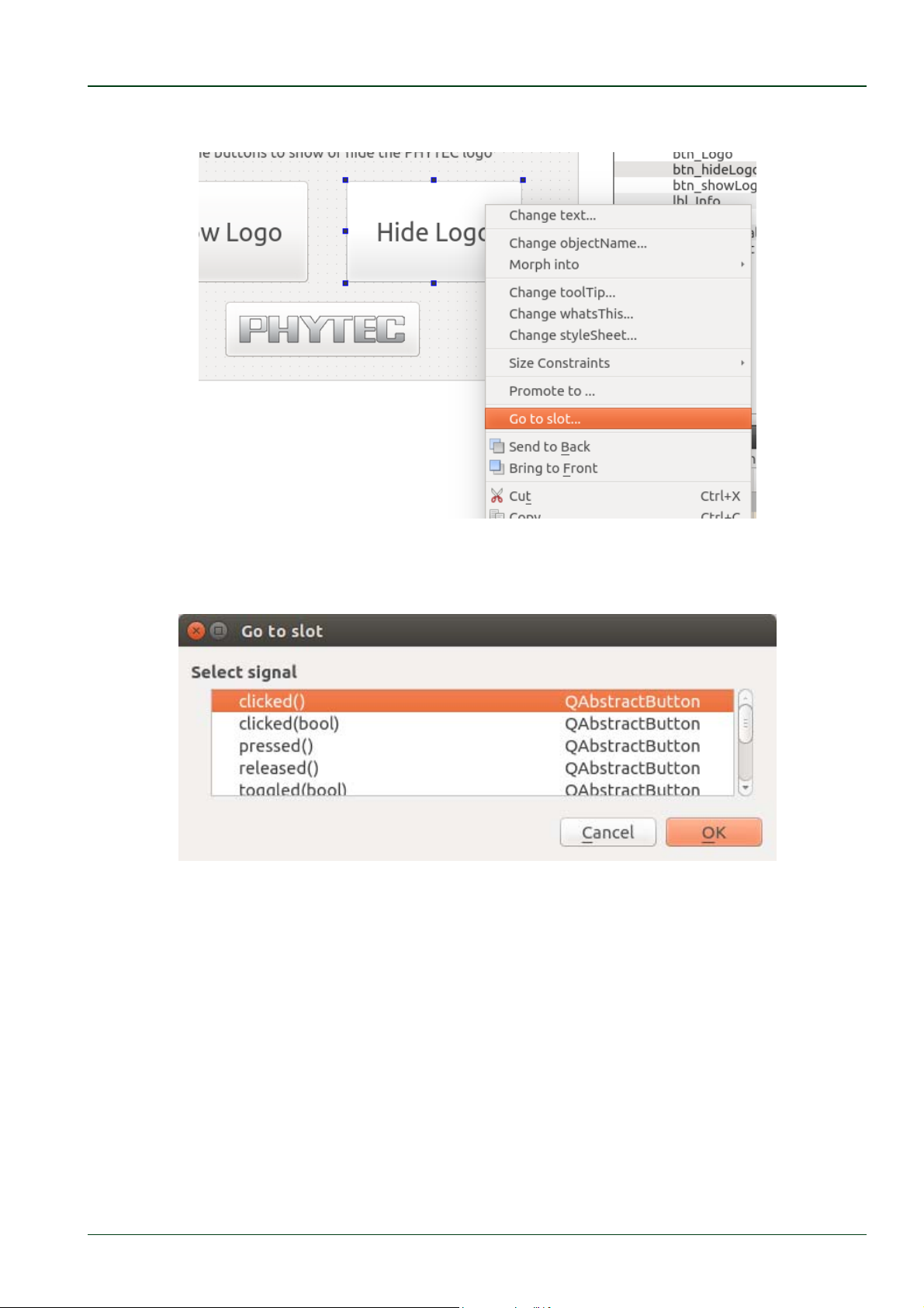
Right-click the “Hide Logo” button and select Go to slot … from the context menu.
A window opens allowing you to select a signal.
Select clicked() and click OK.
© PHYTEC Messtechnik GmbH 2016 L-779e_6 47
Page 54
phyCORE®-AM335x [PCM-051-xxx]
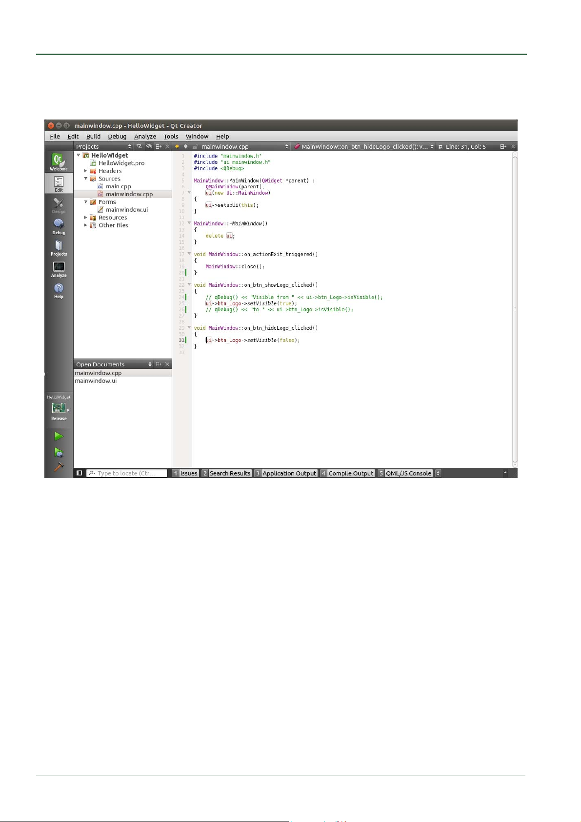
Now Qt Creator jumps into the mainwindow.cpp where you can find the definition of the
function on_btn_hideLogo_clicked(). You see that clicking this button changes the status
of the btn_Logo button from visible to hidden.
Next we build and run the example.
© PHYTEC Messtechnik GmbH 2016 L-779e_6
48
Page 55
Working with Qt Creator
4.4 Compile and Run the Demo Application on the Target
Now we want to compile and run the demo application on the phyCORE-AM335x.
To carry out the steps described in this section and section 4.6 you need an RDK with
display and touchscreen. If your kit does not include a display continue with section 4.5.
The correct Qt settings are already preset in the virtual machine, so the project can be build
directly.
If you want to check the settings click Tools ►Options… in the menu bar.
A new dialog appears. Click Build & Run if it is not already selected. Now,
you can select different tabs to see the settings for the workspace,
compiler, debugger, Qt version and a lot other options.
Be sure that the target is connected via Ethernet and is powered on. As
described before do not forget to stop all actually running Qt applications
on the target.
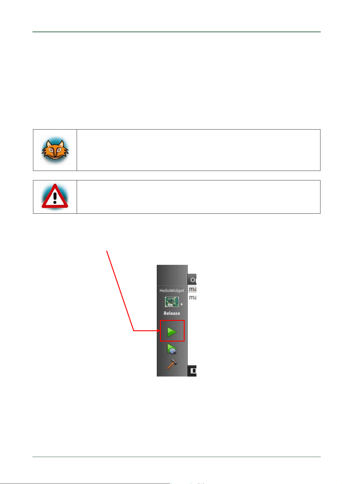
With only one click the project will be built, deployed to the target and executed.
Click the green filled triangle near the bottom of the gray bar on the left.
© PHYTEC Messtechnik GmbH 2016 L-779e_6 49
Page 56
phyCORE®-AM335x [PCM-051-xxx]
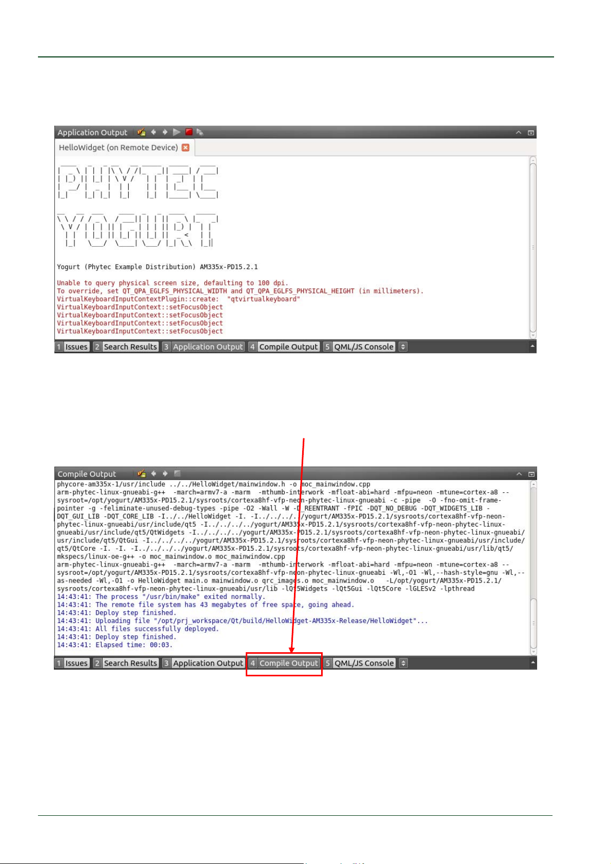
After the target is successfully deployed onto the target the Application Output frame is
shown in the frame under the mainwindow.cpp source code where you can see the prompt
from the phyCORE-AM335x.
On the connected display you will see the HelloWidget application. Click the big button with
the Phytec logo to enable and disable the Welcome label.
To see the different build steps click Compile output which can be found in the bottom
menu bar.
The Compile output frame is opened and you can scroll threw through the compile steps.
© PHYTEC Messtechnik GmbH 2016 L-779e_6
50
Page 57
Working with Qt Creator
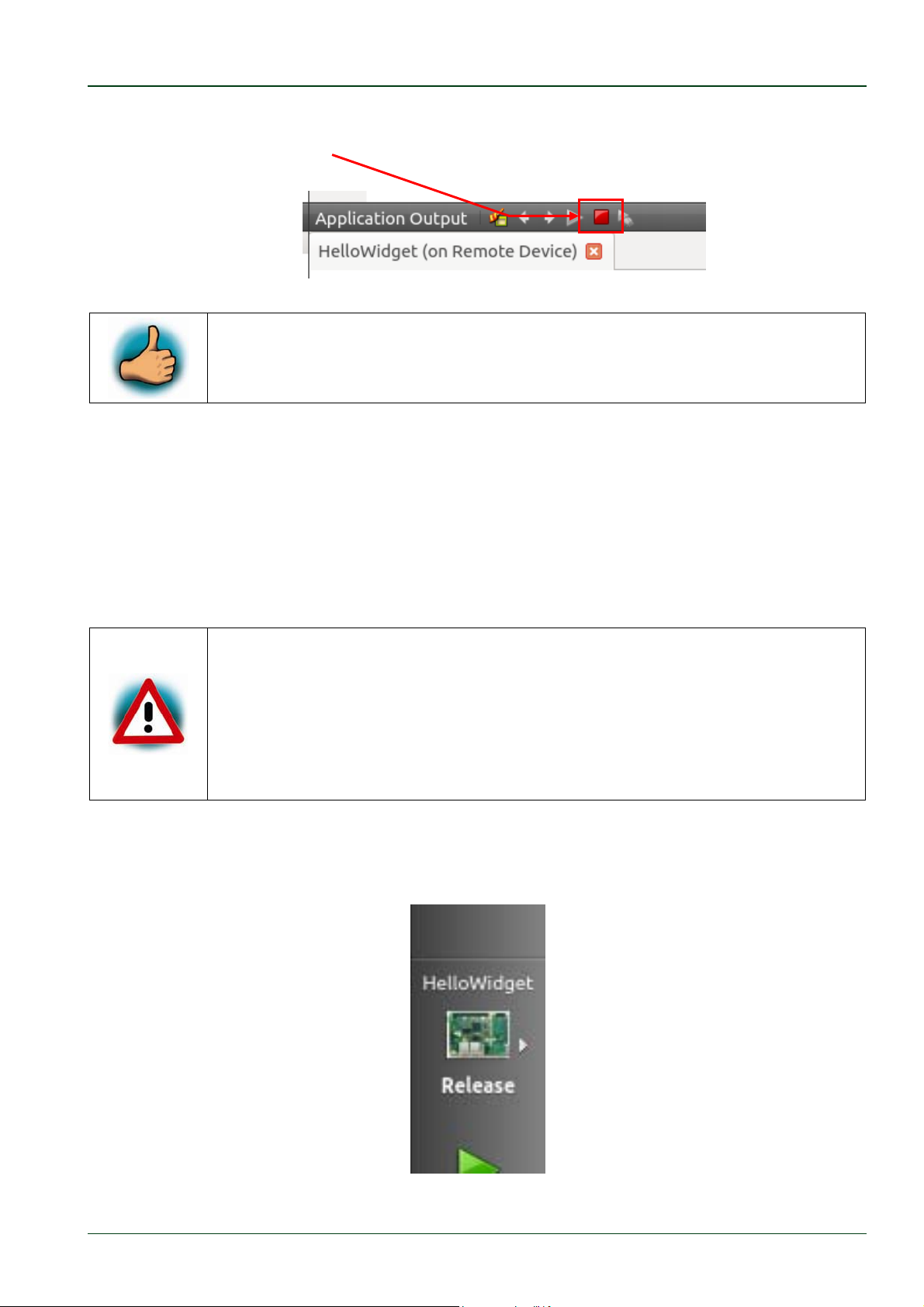
If you want to stop the application on the target switch back to the Application output
frame and click the red rectangle there.
You have successfully imported and built a Qt project with Qt Creator.
You have also learned how to download and execute your application on
the target.
4.5 Compile and Run the Demo Application on the Host
In some cases you do not want to compile and run the application on the target. For
example if the phyCORE-AM335x is not connected to the host or if you only changed some
user interface relevant things and you do not want to copy the application and all the
necessary resources to the target. Running the demo application on the host is faster, but
features specific to the target do not work.
Remember that Qt Creator starts with a link to the target’s environment. If
you want to debug the application on the host you must uncomment the
first line in /usr/bin/qtcreator.sh
./opt/yogurt/AM335x‐PD15.2.1/environment‐setup‐cortexa8hf‐
(
vfp‐neon‐phytec‐linux‐gnueabi)
After that you can use GDB with the host’s environment.
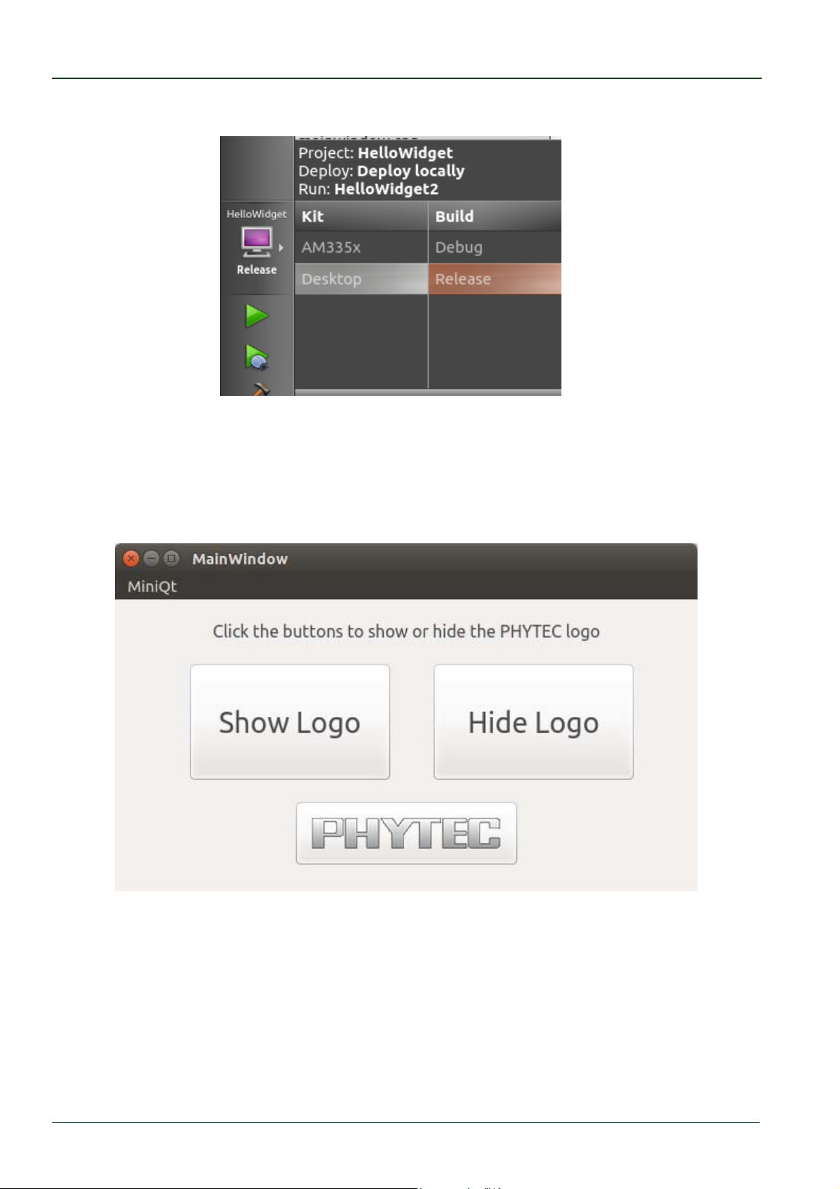
To change the target for downloading and running the application do the following steps:
In the gray bar on the left-click the button with the small picture of the Phytec module.
© PHYTEC Messtechnik GmbH 2016 L-779e_6 51
Page 58
phyCORE®-AM335x [PCM-051-xxx]
In the opened context menu select Desktop as Kit and Release as Build.
Click outside of the context menu to close it.
Now you can start the compilation and execution of the application by clicking the green
triangle.
After the application is compiled a window opens displaying the application running.
Close the running application.
© PHYTEC Messtechnik GmbH 2016 L-779e_6
52
Page 59
Working with Qt Creator
4.6 Debugging the Demo Application
We finish the Qt Creator chapter by showing how to debug the HelloWidget demo
application. To carry out the steps described in this section you need an RDK with display
and touchscreen.
4.6.1 Using QDebug for simple Debugging Messages
In our first debugging step we use the QDebug class. This class provides an output stream
for debugging information. It is used whenever the developer needs to write out
debugging or tracing information to a device, file, string or console.
To make use of the QDebug functions QDebug is already included in the header of the file
mainwindow.cpp.
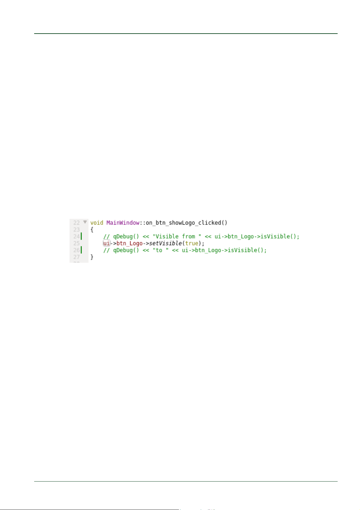
In this file you will also see two out-commented lines in the function
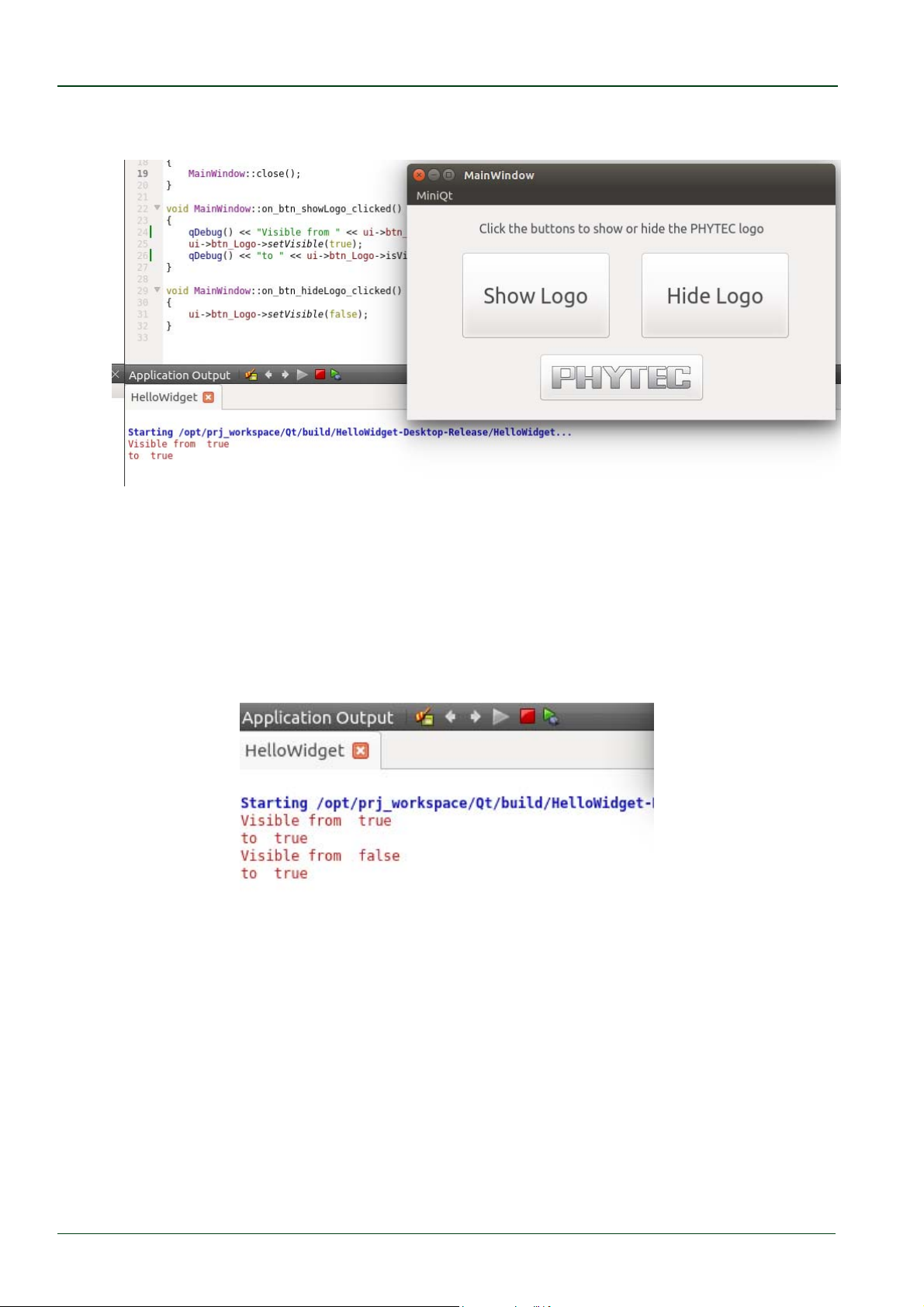
on_btn_showLogo_clicked() which start with a qDebug() command. This is an example how
to make use of qDebug().
Remove the comment flags ( // ) from both "qDebug lines" to enable the two debug
messages.
Save the changes with CTRL + S.
Open the Application Output if it is not already opened.
Build and run the application on the Desktop with the build configuration Release, as it
was shown in the chapter before.
© PHYTEC Messtechnik GmbH 2016 L-779e_6 53
Page 60
phyCORE®-AM335x [PCM-051-xxx]
A window with the running application opens.
Press the Show Logo button.
The logo was visible before we pressed the button so we see the appropriate message from
qDebug() in the Application Output.
Press the Hide Logo button and then the Show Logo button.
Now the logo was hidden before we pressed the Show Logo button again and we see the
appropriate messages from qDebug() in the Application Output.
QDebug is a simple way to generate debug information. In the next chapter we use the
debugger integrated in Qt Creator.
© PHYTEC Messtechnik GmbH 2016 L-779e_6
54
Page 61
Working with Qt Creator
4.6.2 Using the integrated Qt Creator Debugger
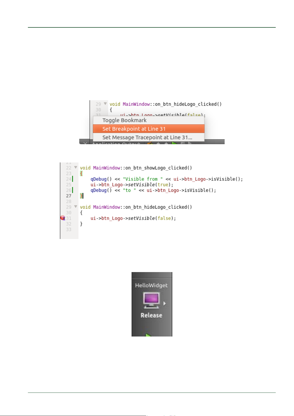
Before we start the integrated Debugger we first set a breakpoint where we want the demo
application to stop.
Open the mainwindow.cpp if it is not already open.
Right-click in front of line number 31.
In the context menu click Set Breakpoint at Line 31 to add a breakpoint.
You now see a red filled circle with a small sand glass in front of this line.
The next step is to change the build configuration from Release to Debug.
In the gray bar on the left-click the button with the small Desktop icon.
© PHYTEC Messtechnik GmbH 2016 L-779e_6 55
Page 62
phyCORE®-AM335x [PCM-051-xxx]
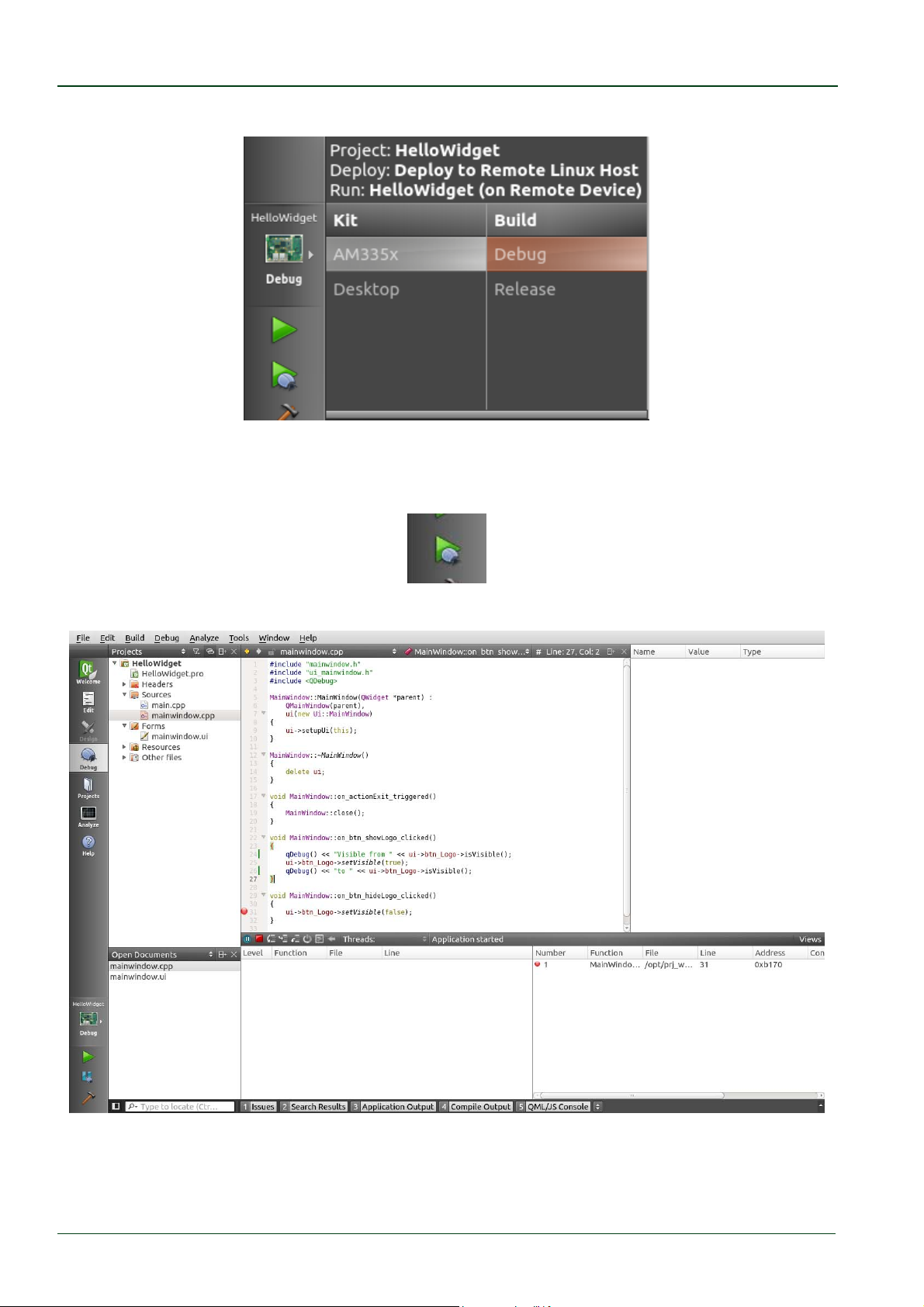
In the opened context menu select AM335x as Kit and Debug as Build.
Be sure that the target is connected via Ethernet to the host.
Start Debugging by clicking on the green filled triangle with the small magnifier.
The debugger starts and Qt Creator changes his view to the Debug mode.
The demo application is shown on the connected display.
© PHYTEC Messtechnik GmbH 2016 L-779e_6
56
Page 63
Working with Qt Creator
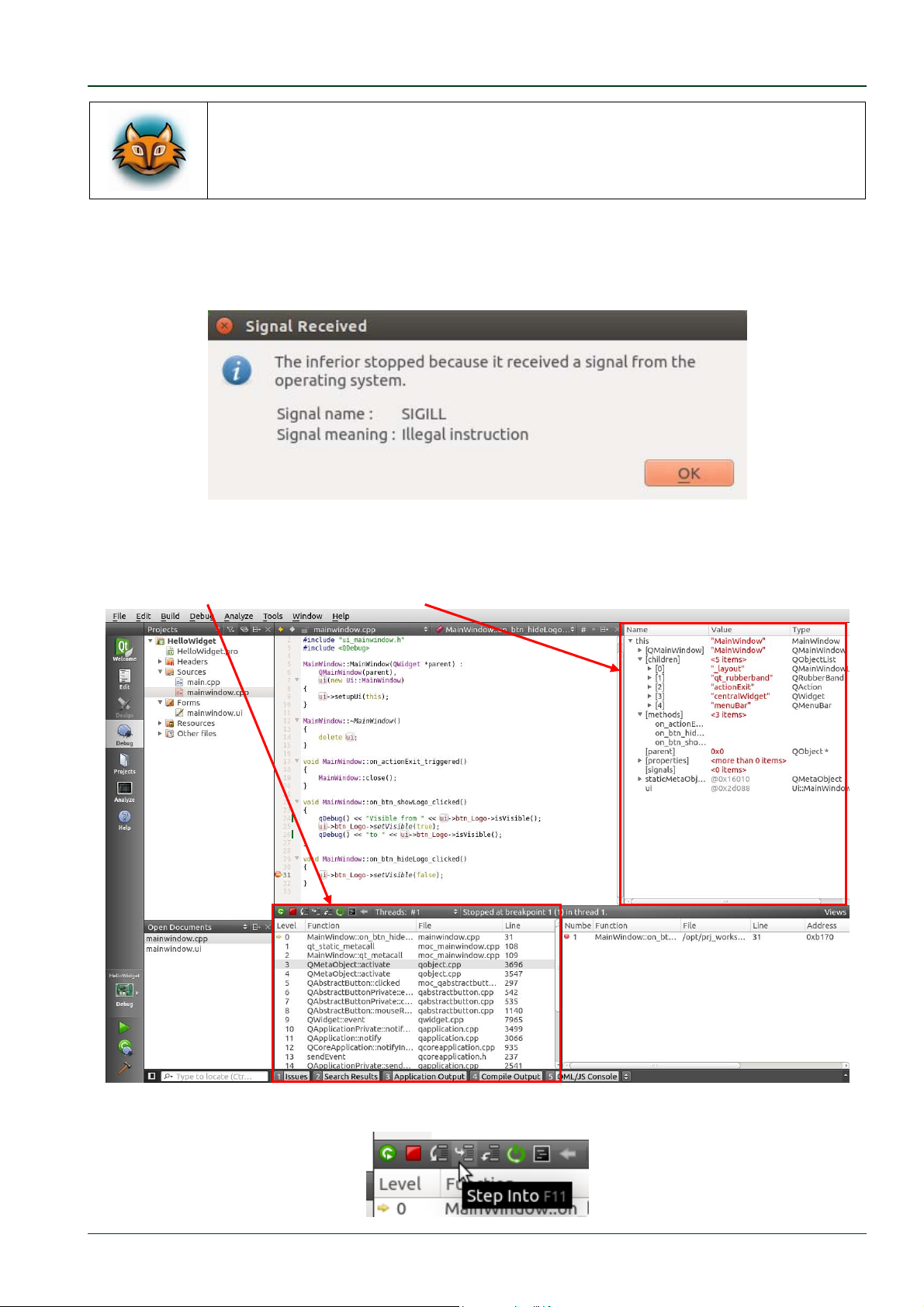
In the Application Output window you will see some warnings regarding
missing dynamic sections. The warnings do not influence the debugging
process and can be ignored.
In the running demo application click the Hide Logo button.
When the button is pressed the debugger receives a SIGILL signal and shows a warning.
This is a normal warning because we use a SSH connection for debugging.
Click OK
The debugger stops at the created breakpoint, because the function is called. You can now
watch the stack, or the Locals and Expressions.
Step into the setVisible function by pressing the Step Into button.
© PHYTEC Messtechnik GmbH 2016 L-779e_6 57
Page 64
phyCORE®-AM335x [PCM-051-xxx]
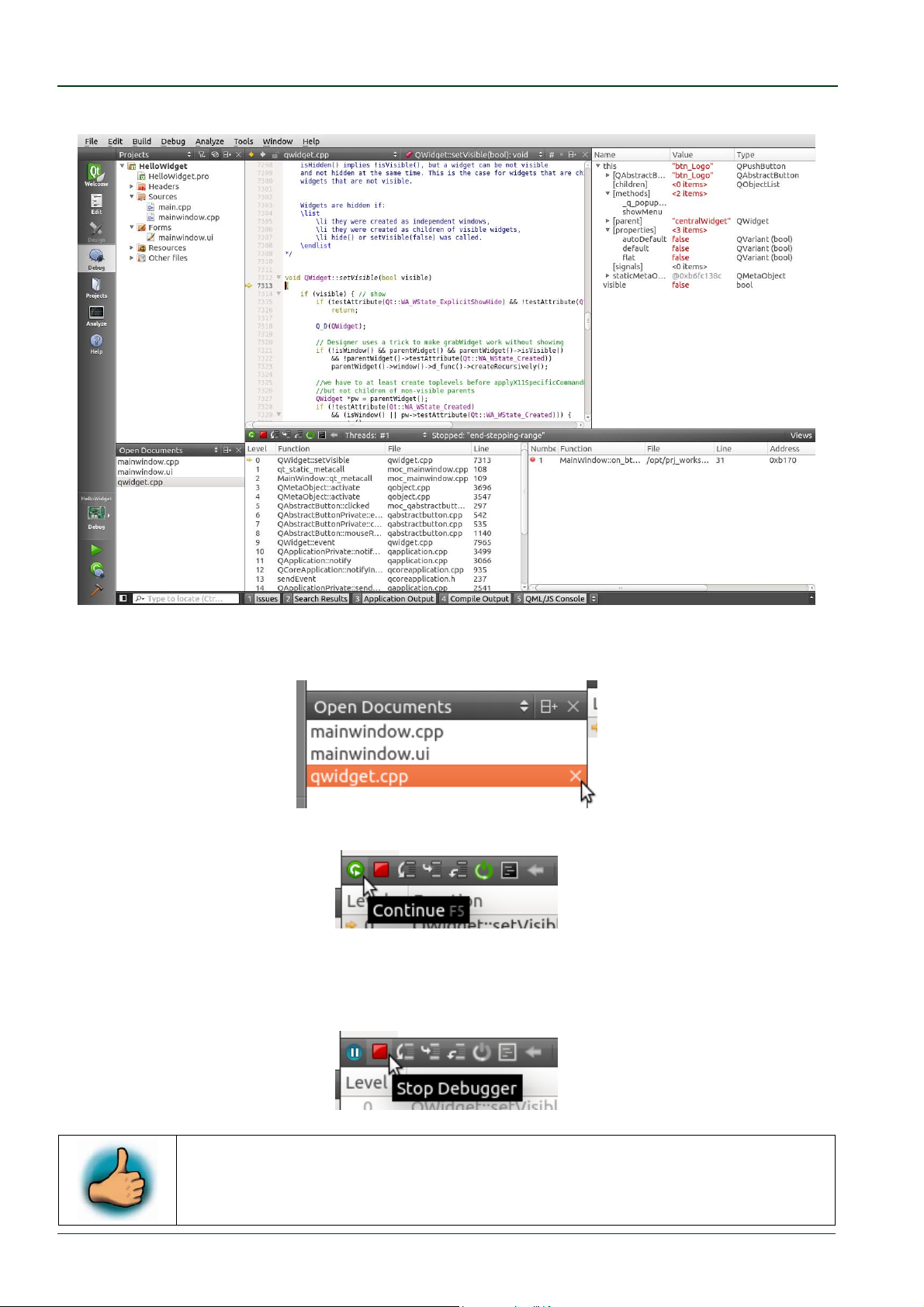
Now the definition of this function is opened.
As many other calls are following it is recommended to close the opened qwidget.cpp.
Close qwidget.cpp in the Open Documents frame by clicking the X on the right side.
Continue the stopped application by clicking on Continue.
Now the demo application is continued and waiting for user interactions.
Stop the Debugger by pressing Stop Debugger.
You have successfully finished our short introduction to the Debugger
from Qt Creator.
© PHYTEC Messtechnik GmbH 2016 L-779e_6
58
Page 65
Getting Started with the BSP
5 Getting Started with the BSP
In this chapter of the QuickStart we describe only the basic Yocto usage.
For in-depth explanations refer to the Yocto Reference Manual.
In this part you will learn how to use the Yocto Project and the Phytec BSP.
5.1 Add new Packages to the Root Filesystem with Yocto
The BSP was pre-build in the virtual machine, but to save disk space some parts were
removed after building. Even so, you will highly benefit from the pre-build BSP, because all
downloads and the shared state (sstate) code are already available.
You can find the pre-build BSP in the virtual machine under /opt/PHYTEC_BSPs/am335x/.
All necessary tools and programs are already pre-installed to directly start with Yocto.
Open a new terminal if you have not already done and change to the directory of the preinstalled BSP:
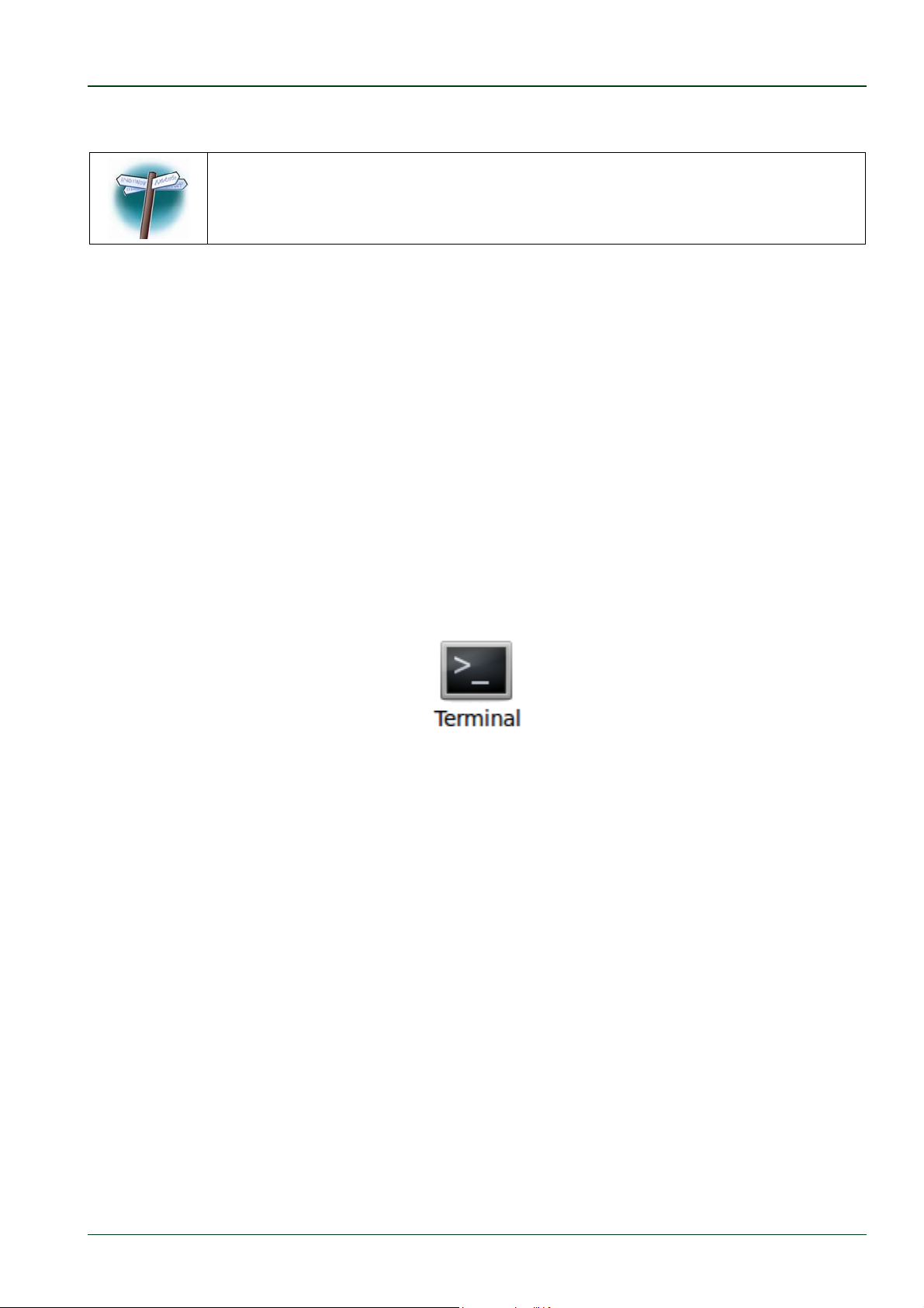
Click the terminal icon on your desktop.
Type the following command to change to the BSP-directory:
cd/opt/PHYTEC_BSPs/am335x/
This directory is the start point for our BSP. You will also find further documents in this
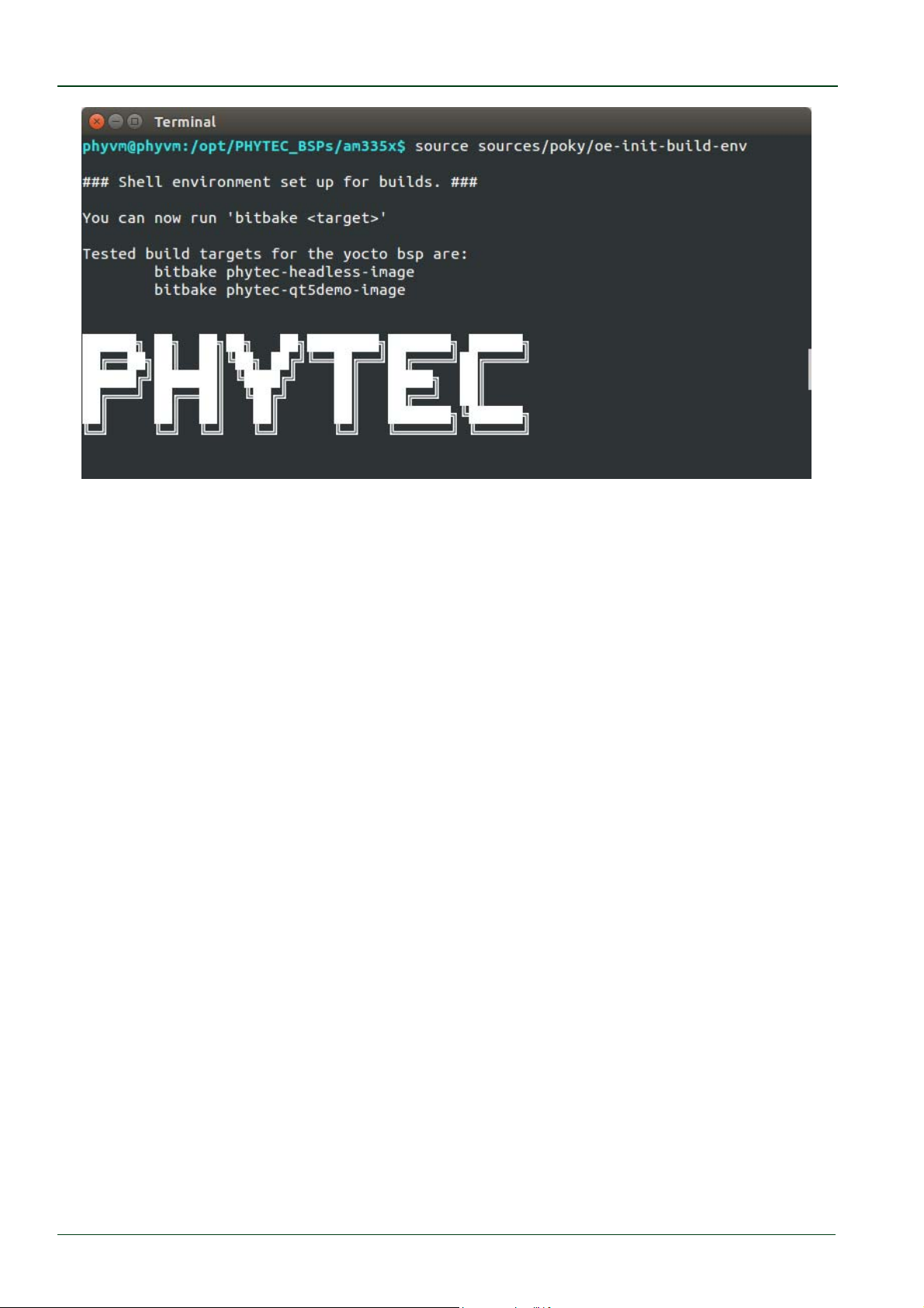
directory. First we must set the correct environment.
Enter the following command sourcesources/poky/oe‐init‐build‐env
© PHYTEC Messtechnik GmbH 2016 L-779e_6 59
Page 66
phyCORE®-AM335x [PCM-051-xxx]
The environment is set and we are now in the build folder. In this example we want to add
the nano editor to the image. Usually new packages are downloaded from an appropriate
server prior to building the image unless they are stored locally. In the virtual machine the
package for the nano editor is already pre-downloaded and available locally.
Before we add the package we check if the right configuration is set.
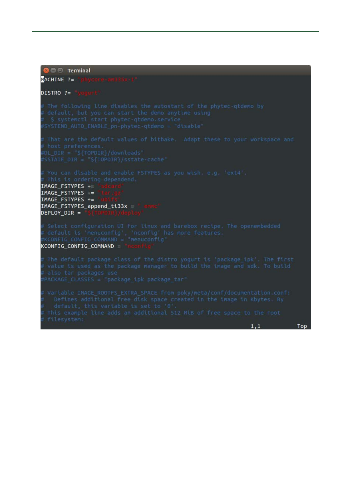
Open the configuration file with any editor, e.g. VI, with the following command:
viconf/local.conf
Check the MACHINE variable in this file.
© PHYTEC Messtechnik GmbH 2016 L-779e_6
60
Page 67
Getting Started with the BSP
By default the variable is set to phycore-am335x-1. This is the correct MACHINE for the
module in the standard RDK (module ordering number PCM-051-12102F0C).
© PHYTEC Messtechnik GmbH 2016 L-779e_6 61
Page 68
phyCORE®-AM335x [PCM-051-xxx]
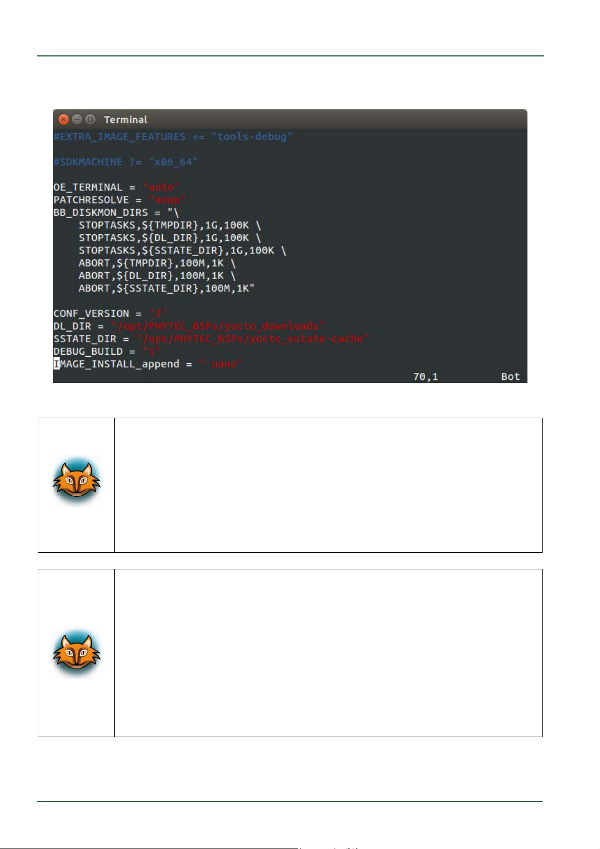
In the same file we can add nano by adding the following line at the end of the file
IMAGE_INSTALL_append=“nano”
Save the changes and close the file with :x and Enter.
If you do not have the standard RDK you can find the appropriate value
for the MACHINE variable on our website at
http://www.phytec.de/produkte/software/yocto/phytec-unified-yocto-bspreleases/.
Click the corresponding BSP release and look for the ordering number of
your module in the column "Hardware Article Number". Now you can find
the correct machine name in the corresponding cell under "Machine
Name".
You can search for more available packages at:
http://layers.openembedded.org/layerindex/branch/master/recipes/
Be sure that the layer on which the package depends is in our BSP. You
can check our integrated layers in the file conf/bblayers.conf .
When your needed layer is not in our BSP you must first checkout the
layer to the folder /opt/PHYTEC_BSPs/am335x/source/ .
Please note that there is no a guarantee that the build process proceeds
successfully with all new packages added.
© PHYTEC Messtechnik GmbH 2016 L-779e_6
62
Page 69
Getting Started with the BSP
Now you can start building the configured BSP. There are two methods to
create the images. You can use either bitbake phytec-hwbringup-image, or
bitbake phytec-qt5demo-image
The first option leads to a faster compilation and smaller images, because all Qt relevant
features are left out.
In our example we want to keep the Qt relevant features, so we type following command:
bitbakephytec‐qt5demo‐image
Because of dead links it is possible that an attempt to download a source
package fails. Every week Phytec checks the accessibility of all the
packages in the BSP and updates links to the mirrors if necessary.
If you nonetheless discover a missing package please send an email to
Among other images you will find the kernel named zImage, the device tree named zImageam335x-phycore-rdk.dtb and the root filesystem named phytec-qt5demo-image-phycoream335x-1.ubifs in the directory deploy/images/phycore-am335x/.
The three files are only a symbolic link to the correct images with the timestamp of the
build date.
For more information about how to work with Yocto, please refer to our
Yocto Reference Manual (L-813e) and the appropriate BSP Manual
(L-818e).
5.2 Writing the Root Filesystem into the Target’s Flash
In this section you will find a description on how to write the newly created root filesystem
into the phyCORE-AM335x’s Flash memory. Before the images can be written into the
Flash, it must be uploaded to the phyCORE-AM335x from a TFTP server. This will be done
from the command line of the bootloader. The partition of the root filesystem will be
formatted. Then the image will be downloaded over TFTP to the created Flash partition.
You should never erase the barebox partition. If this partition is erased,
you will not be able to start your target anymore. In such a case, refer to
our BSP Manual section "Updating the Software".
The versions of the barebox and the Linux kernel must match. Therefore
the following steps should only be done using the hardware that was
shipped together with the virtual machine and thus already contains the
same version of the BSP.
© PHYTEC Messtechnik GmbH 2016 L-779e_6 63
Page 70
phyCORE®-AM335x [PCM-051-xxx]
First open a new terminal window if it is not opened yet. Then change to the directory
/opt/PHYTEC_BSPs/am335x/build/deploy/images/phycore-am355x-1/
Copy the root filesystem to the folder /tftpboot:
cpphytec‐qt5demo‐image‐phycore‐am335x‐1.ubifs/tftpboot/
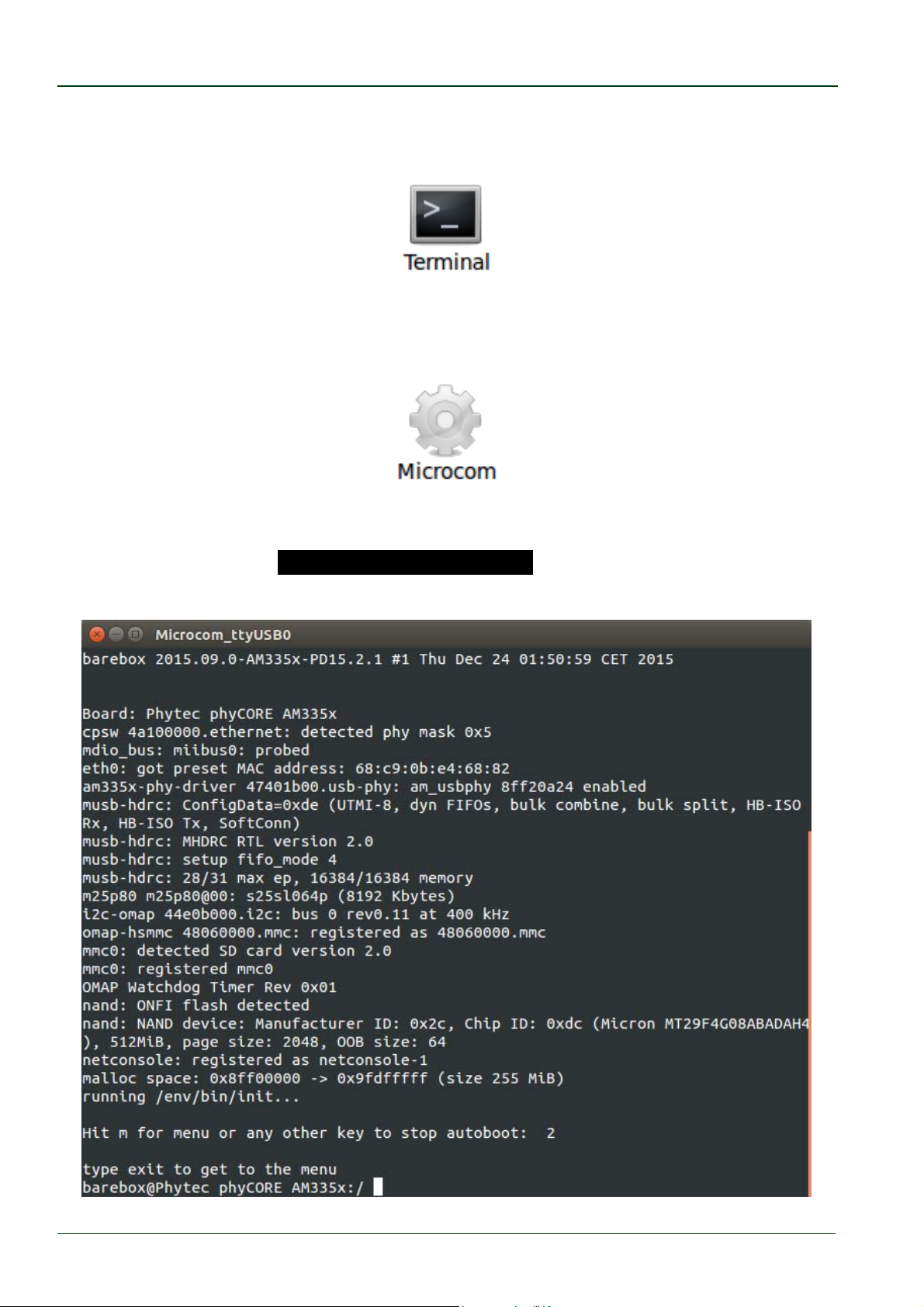
Open Microcom and press the RESET button on the target.
You will see the output .Hit any key to stop autoboot..
Press any key to stop autoboot.
© PHYTEC Messtechnik GmbH 2016 L-779e_6
64
Page 71
Getting Started with the BSP
Check the network settings with following command:
ifupeth0
devinfoeth0
The target should return these lines:
..ipaddr=192.168.3.11..... e
..netmask=255.255.255.0. ic
..gateway=255.255.255.0. .
..serverip=192.168.3.10...ev
If you need to change something, type:
edit/env/network/eth0
edit the settings, save them by leaving the editor with CTRL-D, then typesaveenv and
reboot the board.
Now we flash the root filesystem. Type:
ubiformat/dev/nand0.root
ubiattach/dev/nand0.root
ubimkvol/dev/nand0.root.ubiroot0
cp/mnt/tftp/phytec‐qt5demo‐image‐phycore‐am335x‐1.ubifs
/dev/nand0.root.ubi.root
Enter boot to boot the phyCORE-AM335x with the new kernel and root filesystem.
After the target has successfully finished booting, type
root to log in.
Now we can test the newly installed editor nano by trying to open a file with it.
Enternano/etc/profile.
Close nano by pressing CTRL+X.
Close Microcom after nano is closed.
Troubleshooting:
If any problem occurs after writing the kernel or the root filesystem into
the Flash memory, you can restore the original kernel (zImage) from the
/tftpboot directory. The root filesystem is available in the following
directory of the virtual machine:
/opt/PHYTEC_BSPs/am335x/build/deploy/images/phycore-am335x1/phytec-qt5demo-image-phycore-am335x-1.ubifs
All files are also downloadable from our FTP server. If you want other
versions also check our FTP server:
ftp://ftp.phytec.de/pub/Software/Linux/BSP-Yocto-AM335x/
For more information about how to update the software on our target,
please refer to our BSP Manual section "Updating the Software".
© PHYTEC Messtechnik GmbH 2016 L-779e_6 65
Page 72
phyCORE®-AM335x [PCM-051-xxx]
In this section you learned how to prepare the partition of the root
filesystem and how to download the root filesystem from a TFTP server
into the Flash of the target.
© PHYTEC Messtechnik GmbH 2016 L-779e_6
66
Page 73
Setup your own Linux Host PC
6 Setup your own Linux Host PC
This chapter is for developers who want to get a native environment with the same
modifications as in our virtual machine hard disk image or for developers who want to use
their own existing environment. We will give an overview of the modifications which we
made to the Ubuntu version in the virtual machine hard disk image in comparison to the
original Ubuntu in this chapter. In the following we distinguish between optional and
essential modifications. So you can see easily which changes are important to execute this
QuickStart in case you do not want to use our modified Ubuntu version. The following stepby-step instruction is based on the use of Ubuntu 14.04.4.
We can not guarantee that the presented changes are compatible to other
distributions or versions. If you want to use another distribution, it might
take a lot of individual initiative. We do not support other distributions.
You should be sure about what you do.
6.1 Essential Settings
In the following section you get a short instruction about the important settings which are
essential to guarantee the execution of the examples in this QuickStart.
6.1.1 Installing Ubuntu
We recommend to have at least 80 GB of free disk space available.
Before we can start with the modification we must first install Ubuntu.
Download Ubuntu 14.04.4 LTS from www.ubuntu.com and create a bootable medium.
Boot Ubuntu from your created boot medium.
© PHYTEC Messtechnik GmbH 2016 L-779e_6 67
Page 74
phyCORE®-AM335x [PCM-051-xxx]
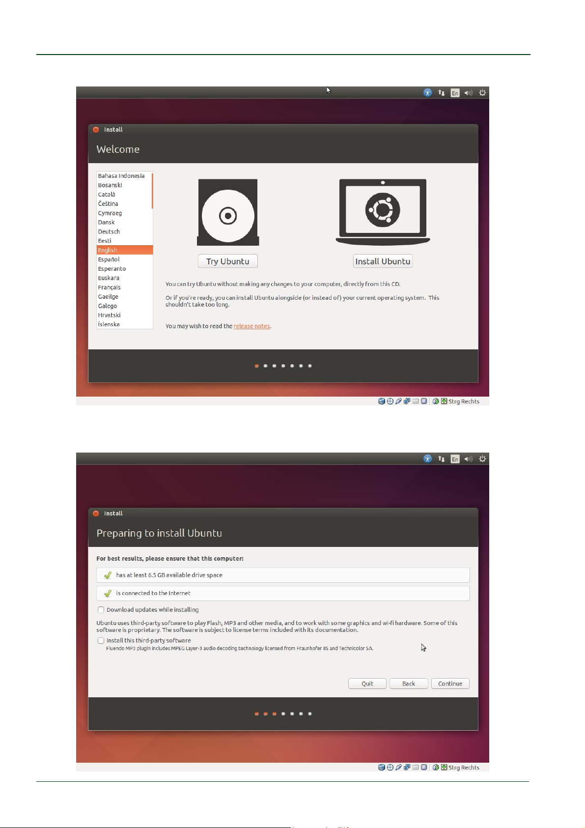
Select Install Ubuntu in the first Welcome window.
The Preparing to install Ubuntu… window appears. From Ubuntu it is advised that you
select Download updates while installing and Install this third-party software now.
© PHYTEC Messtechnik GmbH 2016 L-779e_6
68
Page 75

Setup your own Linux Host PC
Click Continue.
The Installation type window appears. You now have different options how to install
Ubuntu. Depending on your system you have a number of possibilities that are shown in
the dialog.
Chosen one and click Continue.
The Install Ubuntu... window appears. After you have checked the settings you can click
Install now.
While the installation is started Ubuntu asks for your location, keyboard layout and login
and password details.
Please insert this information and wait until the installation is finished.
Finally you must restart your system after the installation is finished.
After that the system boots up and you can log into Ubuntu.
Configure your network connection now and connect the phyCORE-AM335x.
6.1.2 Installation of Software Packages
First of all various software packages that are required must be installed using the package
manager APT.
To gain a better understanding of the packages required, they are installed separately
according to their function:
1. Packages which are needed for compiling and building the Board Support Package:
sudoapt‐get‐yinstallgawkwgetgit‐corediffstatunziptexinfo
gcc‐multilibbuild‐essentialchrpathsocatlibsdl1.2‐devxterm
2. Packages for development
sudoapt‐get‐yinstallvimeclipsemeld
3. Packages to set up the TFTP server:
sudoapt‐get‐yinstalltftpd‐hpa
During installation some programs may ask for a license agreement. Just go through the
steps shown on the screen.
The first preparations are completed. In the next sections you will proceed with building
the Board Support Package installation of Eclipse and Qt Creator and the set up of the TFTP
server.
© PHYTEC Messtechnik GmbH 2016 L-779e_6 69
Page 76

phyCORE®-AM335x [PCM-051-xxx]
6.1.3 Set the Git Configuration
The Board Support Package is heavily based on Git. Git needs some information from you as
a user to be able to identify which changes were done by whom. So at least set the name
and email in your Git configuration, otherwise building the BSP generates many warnings.
Enter following two commands to directly set them
gitconfig‐‐globaluser.email“your_email@example.com”
gitconfig‐‐globaluser.name“namesurname”
6.1.4 Build the Board Support Package and Install the SDK
In this chapter we build our Board Support Package with the help of the Yocto Project.
First we create a folder for the BSP in our example we use the path as it is in our virtual
machine
Enter the following commands:
sudo mkdir‐p/opt/PHYTEC_BSPs/am335x/
sudochmod‐R777/opt/PHYTEC_BSPs/
cd/opt/PHYTEC_BSPs/am335x/
Download the phyLinux script and set execution privileges:
wgetftp://ftp.phytec.de/pub/Software/Linux/Yocto/Tools/phyLinux
chmod+x./phyLinux
The phyLinux script is a basic management tool for Phytec Yocto BSP releases. It is mainly a
tool to get started with the BSP structure. You can get all the BSP sources without the need
of interacting with Repo or Git.
Start the phyLinux script
./phyLinuxinit
During the execution of the init command, you need to choose your processor platform
(AM335x), Phytec's BSP release number (PD15.2.1) and the hardware you are working on
(phycore-am335x-1
1
).
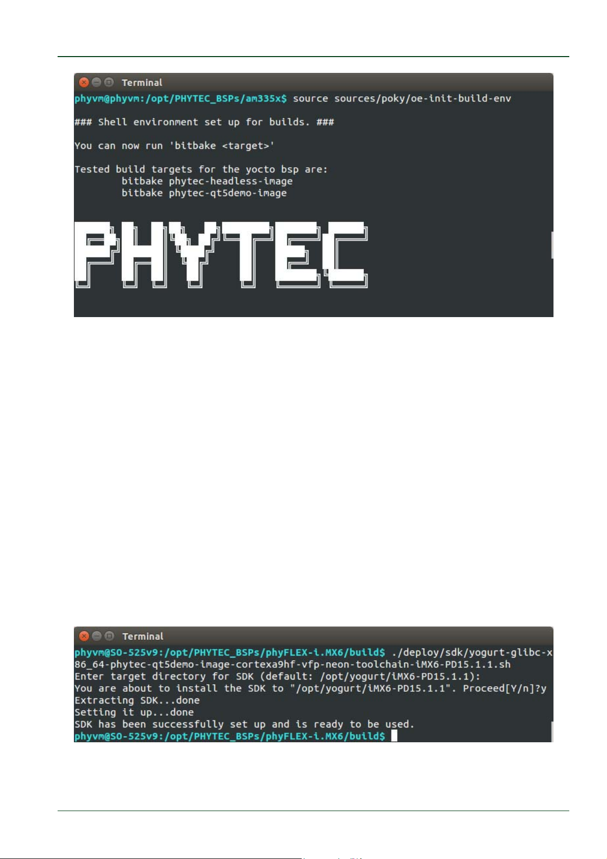
After you downloaded all the meta data with phyLinux, you have to set up the shell
environment variables. This needs to be done every time you open a new shell for starting
builds. We use the shell script provided by Poky in its default configuration.
Type:
sourcesources/poky/oe‐init‐build‐env
1
: If you do not have the standard RDK you can find the appropriate value for the MACHINE variable on our website at
http://www.phytec.de/produkte/software/yocto/phytec-unified-yocto-bsp-releases/. Click the corresponding BSP release
and look for the ordering number of your module in the column "Hardware Article Number". Now you can find the correct
machine name in the corresponding cell under "Machine Name".
© PHYTEC Messtechnik GmbH 2016 L-779e_6
70
Page 77
Setup your own Linux Host PC
The current working directory of the shell should change to build/. To prepare the BSP for a
later development with Eclipse and QtCreator, we change the configuration file.
Open local.conf:
viconf/local.conf
Add DEBUG_BUILD=“1” at the end of the file
Close and save the file with :x and Enter
Now you are ready to build your first images.
Build the BSP:
bitbakephytec‐qt5demo‐image
Generate the SDK needed for Eclipse and Qt Creator:
bitbakephytec‐qt5demo‐image‐cpopulate_sdk
Install the SDK into the recommended default directory:
deploy/sdk/yogurt‐glibc‐*.sh
./
© PHYTEC Messtechnik GmbH 2016 L-779e_6 71
Page 78
phyCORE®-AM335x [PCM-051-xxx]
6.1.5 Set up Eclipse and Integrate Plug-ins
The instructions in this chapter
show how to
setup
Eclipse
and integrate the C/C++
plug
Thus you will be able to assign your own programs, written in Eclipse, to the target.
First of all you have to create a workspace folder, in which you can save your Eclipse
projects.
In this example we create the workspace in the /opt/ directory as it is in the virtual
machine:
mkdir‐p/opt/prj_workspace/Eclipse
sudochmod–R777/opt/prj_workspace/
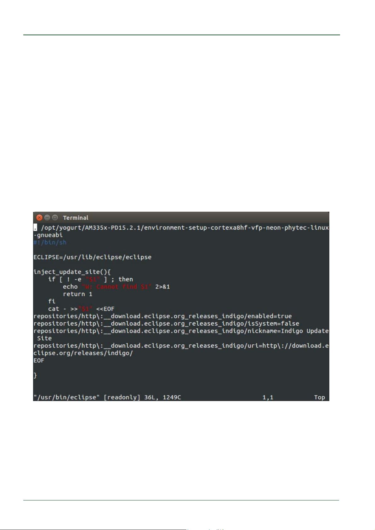
Before we start Eclipse we must set the correct environment to our SDK:
sudo vi/usr/bin/eclipse
Enter following line before #!/bin/sh:
./opt/yogurt/AM335x‐PD15.2.1/environment‐setup‐cortexa8hf‐vfp‐neon‐
phytec‐linux‐gnueabi
-in.
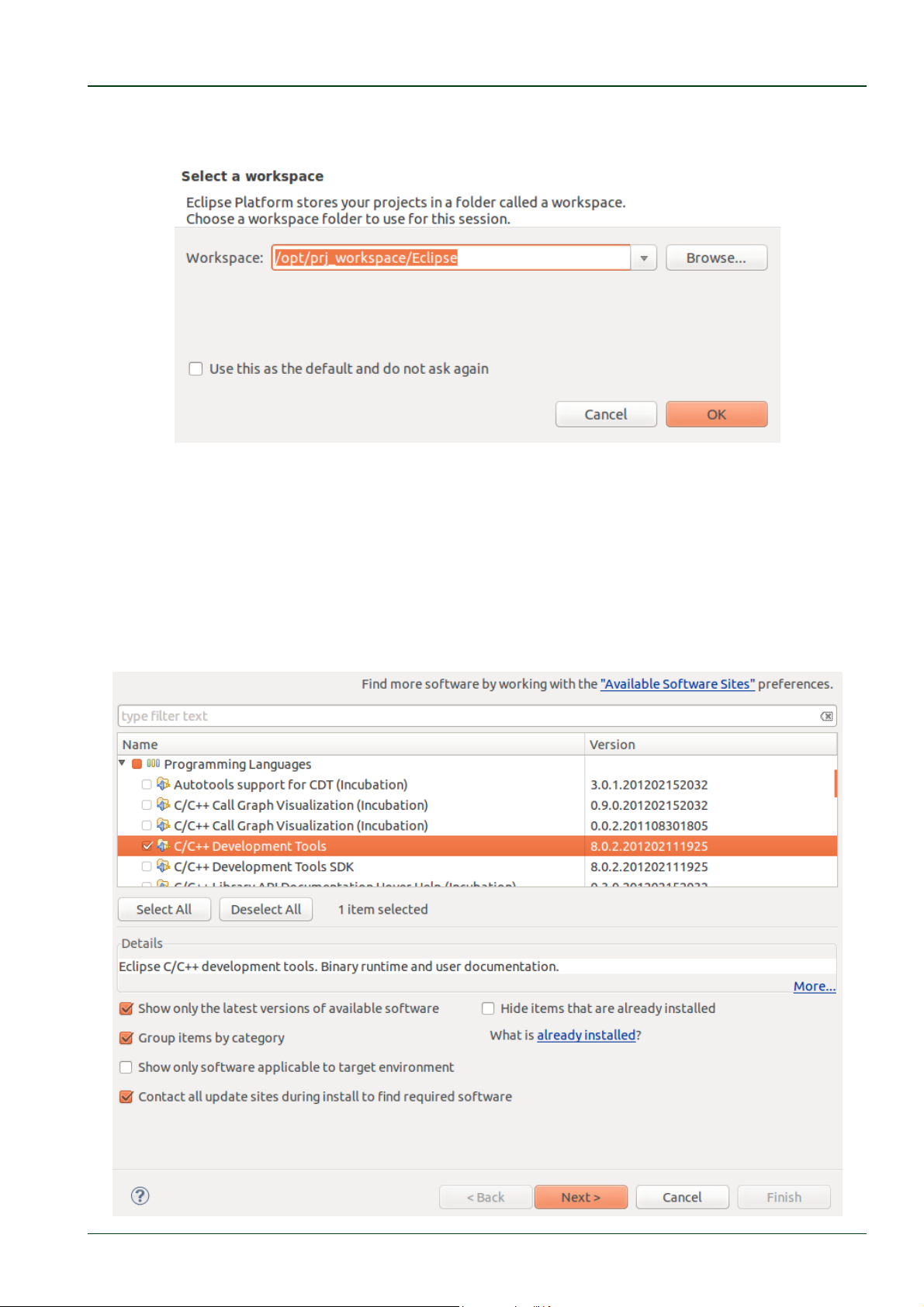
Afterwards open Eclipse and insert the path to the created workspace in the pop-up
window:
eclipse
© PHYTEC Messtechnik GmbH 2016 L-779e_6
72
Page 79
Setup your own Linux Host PC
Enter the path to the created workspace:
/opt/prj_workspace/Eclipse
After Eclipse has started click Help in the menu bar and then Install new Software.
A window opens to add a plug-in to Eclipse.
In the drop-down menu Work with select
Indigo Update Site - http://download.eclipse.org/releases/indigo
The available plug-ins appear in the selection area below now. Expand Programming
Languages and check C/C++ Development Tools. Click Next.
© PHYTEC Messtechnik GmbH 2016 L-779e_6 73
Page 80
phyCORE®-AM335x [PCM-051-xxx]
Now the system displays an overview of the installation details. Click Next to proceed.
Finally accept the licensing agreement and click Finish to start the installation of the
required software.
After that start Eclipse with the option clean, which cleans any cached data:
eclipse‐‐clean
Congratulations! You have successfully integrated the CDT plug-in in
Eclipse and now you can start programming in C/C++. In the next section
you will find a short introduction on how to install and setup the Qt
Creator.
6.1.6 Install and Setup Qt Creator
Because we want the same qmake version as in our BSP we install Qt Creator manually.
Download Qt Creator with following command:
wgethttp://download.qt.io/official_releases/qt/5.4/5.4.2/qt‐
opensource‐linux‐x64‐5.4.2.run
Set execute privileges:
sudochmod+xqt‐opensource‐linux‐x64‐5.4.2.run
Run the Qt Creator installation routine
./qt‐opensource‐linux‐x64‐5.4.2.run
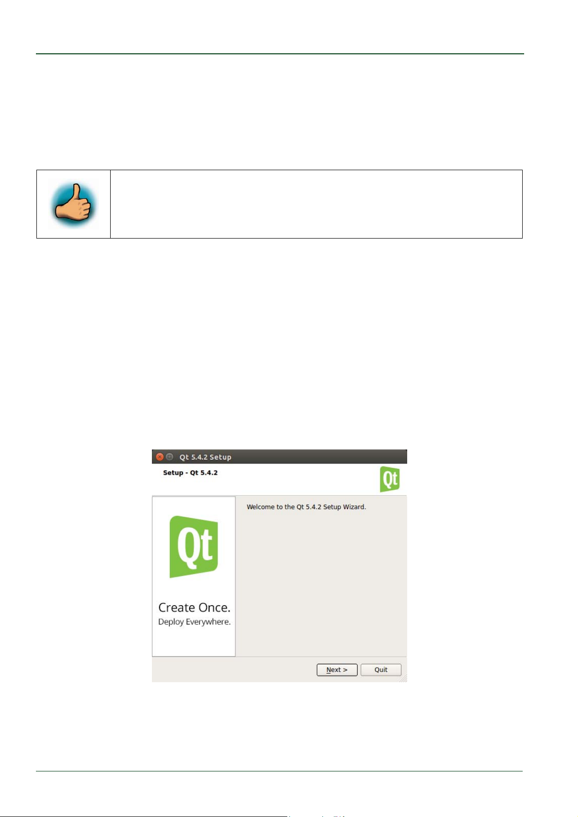
This opens a window for the installation.
© PHYTEC Messtechnik GmbH 2016 L-779e_6
74
Page 81
Setup your own Linux Host PC
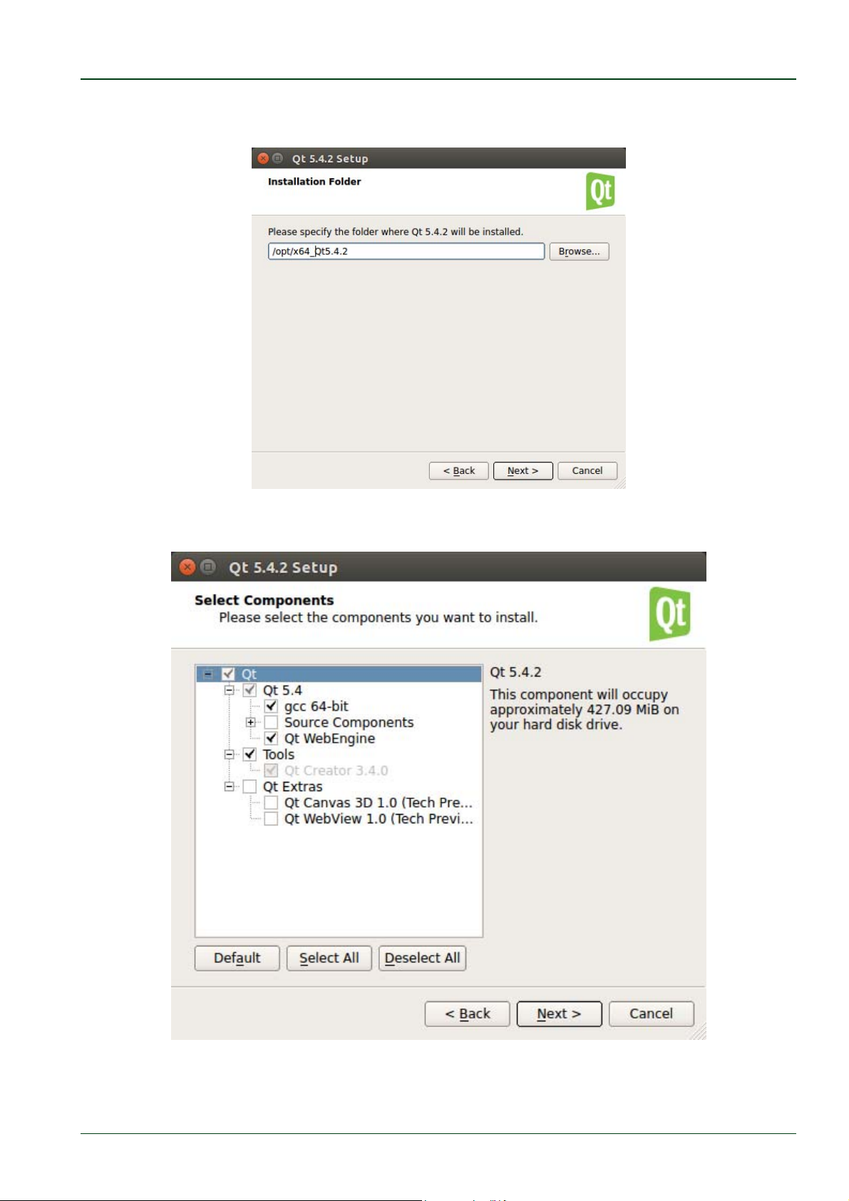
Step trough the installation and if you are asked specify the following installation
directory:
/opt/x64_Qt5.4.2
In the Select Components window select the entries shown in the picture below and click
Next.
Proceed trough the license agreement and start the installation.
© PHYTEC Messtechnik GmbH 2016 L-779e_6 75
Page 82
phyCORE®-AM335x [PCM-051-xxx]
After the installation is finished make a symbolic link to easily start Qt Creator:
sudoln‐s/opt/x64_Qt5.4.2/Tools/QtCreator/bin/qtcreator.sh
/usr/bin/qtcreator.sh
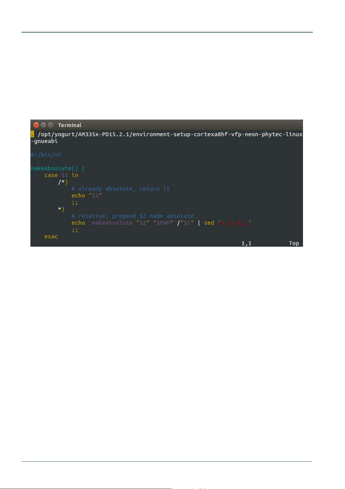
Set the correct environment to our SDK:
sudovi/usr/bin/qtcreator.sh
Enter following line before #!/bin/sh:
./opt/yogurt/AM335x‐PD15.2.1/environment‐setup‐cortexa8hf‐vfp‐neon‐
phytec‐linux‐gnueabi
Create a workspace for Qt Creator e.g.
mkdir‐p/opt/prj_workspace/Qt/build
Start Qt Creator with the following command in a terminal:
/usr/bin/qtcreator.sh
© PHYTEC Messtechnik GmbH 2016 L-779e_6
76
Page 83
Setup your own Linux Host PC
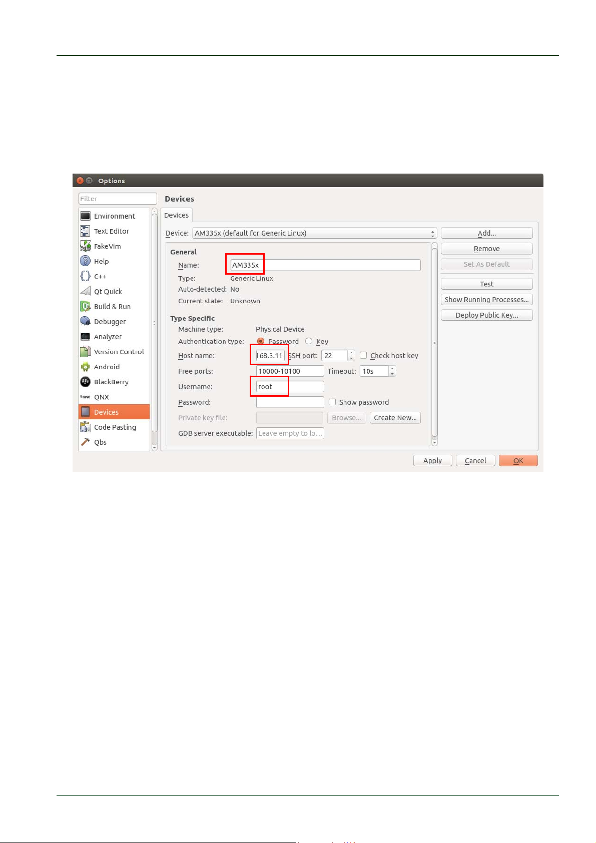
Add the phyCORE-AM335x as device with following inputs by opening
Tools --> Options --> Devices --> Add --> Generic Linux Device:
Name: AM335x
IP: 192.168.3.11
Username: root
Keep the password empty
© PHYTEC Messtechnik GmbH 2016 L-779e_6 77
Page 84
phyCORE®-AM335x [PCM-051-xxx]
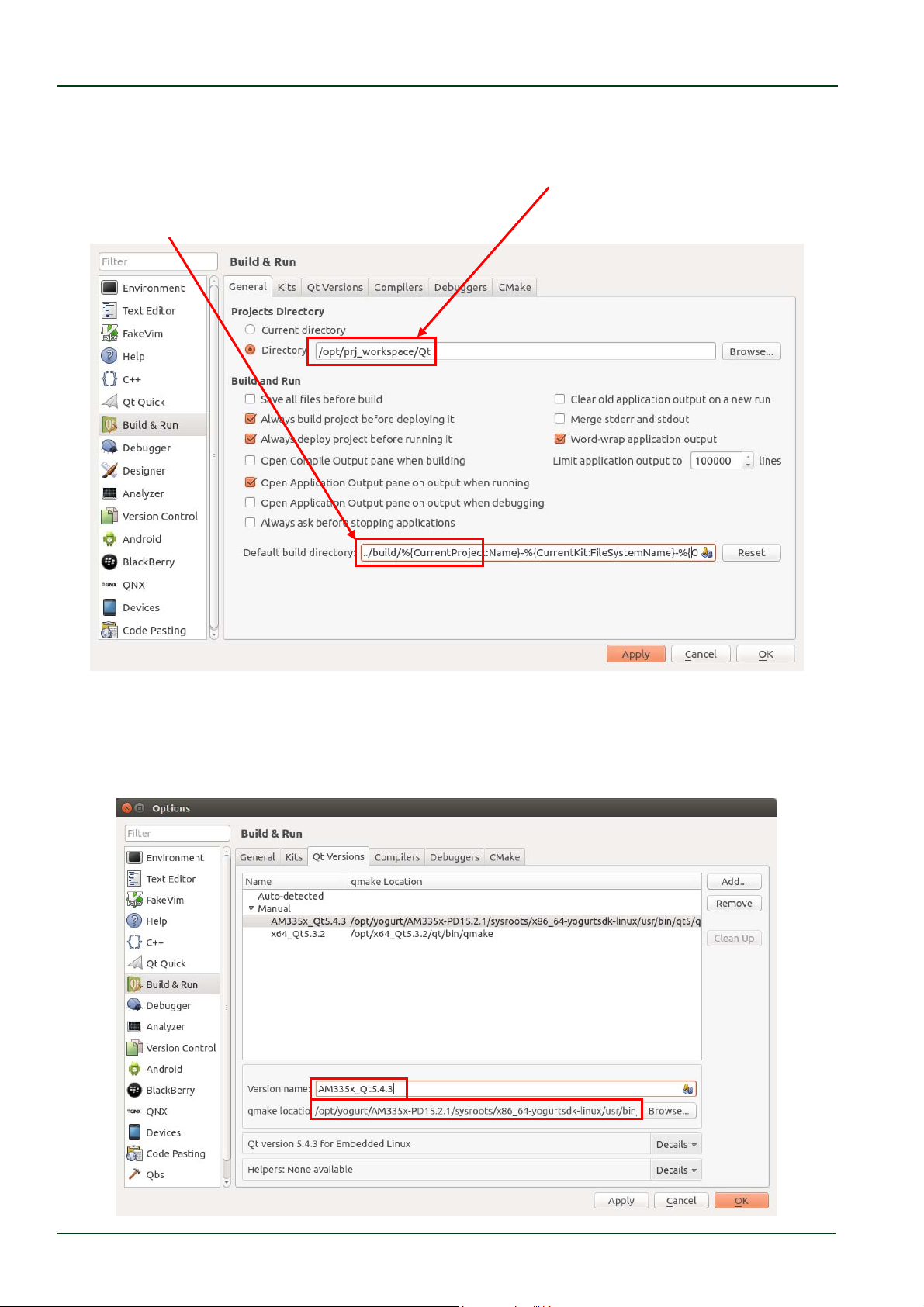
Set the project directory and build directory
Tools --> Options --> Build & Run --> General.
Projects Directory --> Directory:
/opt/prj_workspace/Qt
and change the beginning of the entry in the Default build directory field:
../build/%{CurrentProject:Name}
Select tab Qt Versions and click Add… to add a new one.
Name:
AM335x_Qt5.4.3
qmake Location: /opt/yogurt/AM335x‐PD15.2.1/sysroots/x86_64‐yogurtsdk‐
linux/usr/bin/qt5/qmake
© PHYTEC Messtechnik GmbH 2016 L-779e_6
78
Page 85
Setup your own Linux Host PC
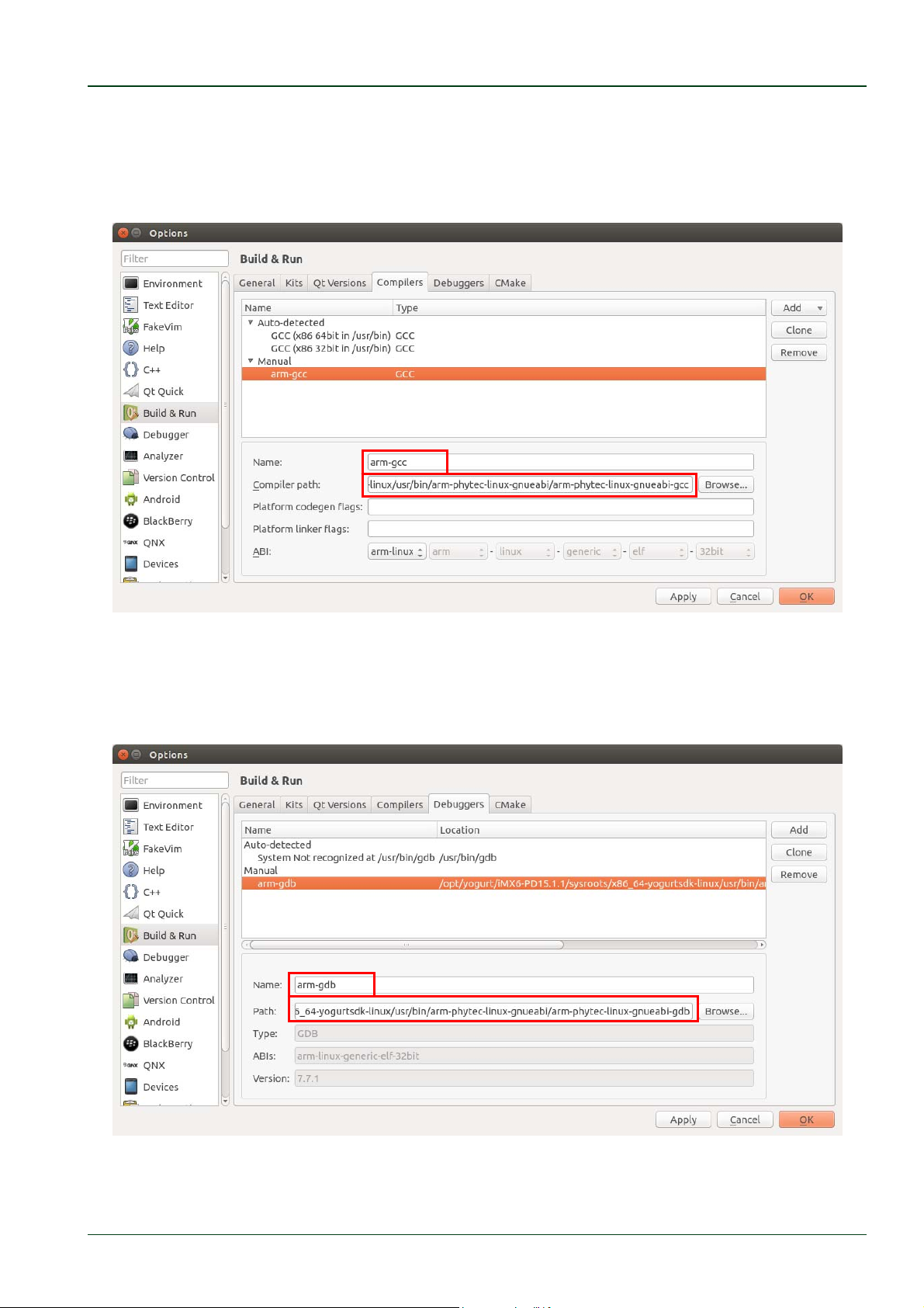
Select tab Compilers and click Add select GCC
Name:
arm‐gcc
Compiler Path: /opt/yogurt/AM335x‐PD15.2.1/sysroots/x86_64‐yogurtsdk‐
linux/usr/bin/arm‐phytec‐linux‐gnueabi/arm‐phytec‐linux‐gnueabi‐gcc
Select tab Debuggers an click Add
Name:
arm‐gdb
Path: /opt/yogurt/AM335x‐PD15.2.1/sysroots/x86_64‐yogurtsdk‐
linux/usr/bin/arm‐phytec‐linux‐gnueabi/arm‐phytec‐linux‐gnueabi‐gdb
© PHYTEC Messtechnik GmbH 2016 L-779e_6 79
Page 86
phyCORE®-AM335x [PCM-051-xxx]
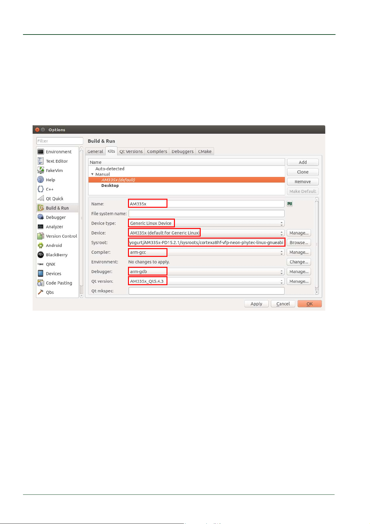
Select tab Kit and click Adds
Name:
AM335x
Device Type:GenericLinuxDevice
Sysroot: /opt/yogurt/AM335x‐PD15.2.1/sysroots/cortexa8hf‐vfp‐neon‐
phytec‐linux‐gnueabi
Compiler: arm‐gcc
Debugger: arm‐gdb
Qt version: AM335x_Qt5.4.3
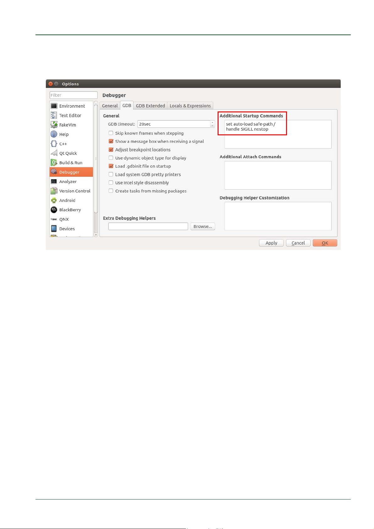
Select Debugger on the left side of the window and click on the GDB tab.
© PHYTEC Messtechnik GmbH 2016 L-779e_6
80
Page 87
Setup your own Linux Host PC
Enter following command in the Addition Startup Commands:
setauto‐loadsafe‐path/
handleSIGILLnostop
Click Apply and close the window with OK.
Now all configurations are done and you can use this Kit to cross compile your application
also if you generate a new project.
6.1.7 Setting up a TFTP server
In the chapter "Installation of software packages" you have installed the required
packages to set up a TFTP server. Now we have to change some short
First
change the file
TFTP_USERNAME="tftp"
TFTP_DIRECTORY="/tftpboot"
TFTP_ADDRESS="0.0.0.0:69"
TFTP_OPTIONS="‐‐secure"
/etc/default/tftp-hpa
as follows:
settings.
Then create a folder called /tftpboot. The TFTP server will access this folder later.
mkdir/tftpboot
Finally we
chmod777/tftpboot
have to set the right permissions:
© PHYTEC Messtechnik GmbH 2016 L-779e_6 81
Page 88
phyCORE®-AM335x [PCM-051-xxx]
Due to a bug in the current version of the TFTP-hpa daemon the daemon
does not start after the system is rebooted. You have to start it in the
terminal with the following command:
restarttftpd‐hpa
A permanent workaround is to create a file called tftp-hpa under
/etc/network/if-up.d/. Insert the following commands in the file:
#!/bin/sh
restarttftpd‐hpa
After saving the file set the correct permission with
chmod755/etc/network/if‐up.d/tftpd‐hpa.
You have successfully set up the TFTP server. In the future the
phyCORE-AM335x can access to the /tftpboot/ folder to load the images.
6.1.8 Optional Settings
In the following section we list the optional settings. These settings are not mandatory for
a successful operation of this QuickStart. They only simplify the handling and the look of
the system. Because of that the modifications are only listed without further explanation.
vim, the improved vi editor is installed.
Desktop-icons for faster and easier start of required programs are created.
The following modifications were made to the look of Ubuntu:
– Other wallpaper and associated options are adjusted with the help of gsettings
– The color of the Gnome terminal is changed.
- The scrolling log for the Gnome terminal is changed.
History-search-backward and history-search-forward in /etc/inputrc is activated.
This allows you to search through your history with the entered string.
Also there are some scripts that will be executed at the first start after the installation.
These scripts ensure that the right permissions are set for the created user.
Congratulations! You have successfully configured your Ubuntu to work
with.
© PHYTEC Messtechnik GmbH 2016 L-779e_6
82
Page 89

Revision History
7 Revision History
Date Version # Changes in this manual
12.09.2012 L-779e_1 First draft
03.12.2012 L-779e_2 Add chapter about QT
Fixed some issues
26.07.2013 L-779e_3 Update Quickstart to work with the Ubuntu 12.04.2 LiveDVD
10.10.2013 L-779e_4 Update Quickstart for working
with PD13.1.0
New barebox handling
Fixed some issues
Remove QT chapter
14.01.2014 L-779e_5 Update Quickstart for working
with PD13.1.2
Fixed some issues
Add QT chapter
15.04.2016 L-779e_6 Change LiveDVD to virtual machine hard disk image
Change ptxdist to Yocto
Update for working with Ubuntu 14.04.4
Update for working with PD15.2.1
Update for working with SO-498v6
Add Programming with Qt Creator
Remove chapter Updating the Software (now in BSP Manual
L-818e)
© PHYTEC Messtechnik GmbH 2016 L-779e_6 83
Page 90

phyCORE®-AM335x [PCM-051-xxx]
© PHYTEC Messtechnik GmbH 2016 L-779e_6
84
Page 91

Suggestions for Improvement
Document: phyCORE-AM335x
Document number: L-779e_6, April 2016
How would you improve this manual?
Did you find any mistakes in this manual? page
Submitted by:
Customer number
:
Name:
Company:
Address:
Return to:
PHYTEC Messtechnik GmbH
Postfach 100403
D-55135 Mainz, Germany
Fax : +49 (6131) 9221-33
© PHYTEC Messtechnik GmbH 2016 L-779e_6
Page 92

Published by
© PHYTEC Messtechnik GmbH 2016 Ordering No. L-779e_6
Printed in Germany
 Loading...