

Page 1
LIFEPAK
94
defibrillator/monitor
PHYSIOCONTROL
ΗΡΕΡΑΚΦΑ
et
ee
AAIOR
Service
Manual
January
Corporate
11811
Post
Redmond,
Telephone:
Toll
Telex:
Telefax:
No.
1994
Headquarters:
Willows
Office
Box
WA
Free:
206/867-4000
800/442-1142
990211 D PHYSIO
206/883-2988
Manual
805378-01
Road
Northeast
97006
98073-9706
USA
or
800/426-8047
RDMD
Page 2
LIFEPAK
9A
defibrillator/monitor
Part
No.
Serial
No.
About
by
technical
test,
troubleshoot,
monitor.
A
separate
intended
personnel.
operating
well
as
This
Manual:
service
publication,
for
use
It
provides
features
operator-level
This
personnel.
and
by
physicians,
of
the
testing
Service
repair
the
Operating
step-by-step
LIFEPAK
Manual
It
describes
the
LIFEPAK
clinicians,
instructions
9A
and
maintenance.
is
intended
how
9A
defibrillator/
Instructions,
and
emergency
for
defibrillator/monitor
for
to
maintain,
is
all
use
care
as
Trademarks
Warranty
PHYSIO-CONTROL*-
QUIK-LOOK * DERMA
and
PARTSLINE™
Willows
Refer
with
the
contact
Road
to
the
product
the
product.
Physio—Control
your
are
N.E.,
PO
warranty
Duplicate
PARTSLINE
local
Physio-Control
LIFEPAK® , FAST-PATCH®,
JEL®,
SAS
trademarks
Box
97006,
statement
copies
at
(SHOCK
of
the
Physio-Control
Redmond,
included
may
be
1-800-442-1142.
sales
or
ADVISORY
WA
in
obtained
service
office.
LIFE*ePATCH®,
SYSTEM)",
Corporation,
98073-9706.
the
accessory
in
the
USA
Outside
the
kit
by
calling
USA,
11811
shipped
ii
All
Rights
Reserved
January
©
Physio-Control
1994
Corporation
Page 3
Table
Safety
of
Contents
Information
General
Information
Description
odt
MOIS
o
Symbols
Service
Effective
Configuration
Content
1
Παυσ
PHYSICAL
Functional
Theory
Power
ue
A
............................................
Information
Publication
OVERVIEW:
DESCTIPLON
Description
of
Operation
Supply
POWER
Regulation:
Overvoltage
Output
BANEN our
BATT
Orne à à à
Isolation
CHRGTAGICAIOF
ο
ο
πο
..................................
Dates
Information
μμ
PCB
Assembly
mms
ps
signori i ian
Protection
....................................
m à
moreno
............................
............................
close
ο
...............................
.................................
(803726)
5 5 e ymm
..............................
o
so.
os
e
ARRE
ο
ο
...................
8
YR
mess à css
more
ER
EEE
sss
ο
ο.
ο.”
a a sonno
和 D ENS
EK
RK
e
RENE
xii
xii
xiii
xiv
XV
xvi
xvii
xviii
1-1
1-1
1-6
1-8
1-8
1-8
1-8
1-8
1-8
1-8
1-9
©
January
1994
Physio-Control
Corporation
All
Rights
Reserved
iii
Page 4
LIFEPAK
9A
defibrillator/monitor
Power
Conversion
O
Lo
BICIBOWELMONIOR
Switching
External
Energy
Low
Capacitor
Energy
Energy
Energy
Serial
Analog
Charge
Interconnect
Main
PCB
RD
System
Display/Recorder
Display
Video
Frame:Sweep
Raster
Raster
Raster:
CRT
Power
Control
Storage
Energy:Charge
Charge
Transfer à à à
DD
Monitor
Datamterfa6e
Voltage
LED
PCB
Assembly
Controller
PCB/CRT
Signal
Scan
Voltage
Generator
Bias
Generator. : :
PCB
Assembly
(803724)
................
6
153
Supply
Input. y sins
Capacitor
Rate... s sn
Control
emmi
νε
εκατο
....................................
Evaluation . .
DAVE
.;
0a
Assembly
(803715)
AAA
..................................
Interface
Assembly
Amplifier
Generator?
Oscillator’
Generator
jee
ss
esin
sl
e
.............................
ss
ramen 3 sürer e 6
Charger
............................
5 & 5
(803761)
dE
...........................
(803706)
..............................
«somos
.............................
segura
sucre
.....................
cranici
gama 8 8 a greenstone
à à à grrr
Perre
cirio в в
44
04 4 sus
i
....................
..........................
GO
É
ELSA
....................
sisas
ss
ss
mms
sonar
isis
se
rene à 6 e
EA
1-9
Hénin à à 9 1-9
mmm
v8 5 1-10
1-11
1-11
1-11
1-12
1-13
a
1-13
Ere
кололи é 1-15
à à
same 6 1-15
öv
ET E GS
a
8
ERE E AE
ee
pores
S 8 2
à
ia
dat
ans
1-14
1-15
1-16
1-16
1-17
1-19
1-24
1-25
1-32
1-34
1-34
1-34
1-34
1-35
1-35
iv
Operation
2
Introduccion:
Controls:and
Option
Test
Setup
Clock:
05s
cases
s a
osa
Indicators; 4 slim
Settings: . .
Menu
...........................................
Menu
.........................................
ci
nbs
cent é Padre à «
4
Pogo
ER
AT
Setting
Procedure
All
Rights
о
Reserved
E
E
A
AE
к
5
+ à č
osseuse k s « « « 2-6
©January
1994
Physio-Control
2-1
2-1
2-7
2-8
2-9
2-10
Corporation
Page 5

^
Testing
3
πω
Performance
PIESPOEDOSE
PIP-Scope
PIP-Definitions
PIP-Requirements
PIP-Required
PIP-Test
PIP=WOTKSAHQN
PIP-Personnel! , z z z zese 5 als
PIP-General
PIP-Physical
A
PIP-Battery
PIP-Batiery
PIP-Setup
ti
PIB-LEGO
PIP-Recorder
PIP-ECG
PIP-lmVCAL.................
PIP-CRT
PIP-Heart
PIP-Recorder
PIPETESEL
PIP-Sync/Sync
PIP-Recorder/CRT
PIP-Defib
PIP-Paddle
PIP-Charge
PIP-Discharge
PIP-Energy
PIP-Charge
FIP-Debivéréd
PIP-Léakage
PIP'Checklišt
Test
and
εδ
πι
TCP-Scope
vos
Inspection
and
Applicability
.......................................
....................................
Equipment
Equipment
Instructions
Inspection
Charge
Power
Menu
Settings
SEIECE
0... 6 cconororesoio
Speed/Baseline
Display
Gain/Aspect
Rate’
OA
.....................................
ws
z z z
Annotation/Real-Time
sus
as
Annotation
Noise
Disarm
and
Polarity
Time
.....................................
Control
Dump:
save 5 5 4
Reduction
Emmy
Current à + à à
..
.
Calibration
1...
.
and
Applicability
ser
dh
Procedure
............................
(PIP)
BG
ES
................
ο
全
生生
.............................
Verification
еее
ария
...............................
................................
>>
esmas
yt a nés à à
........
MM
Ratio
nest
.......................
БКИ
ЗУЕВ
iconos
he à sms
ale v maso
«
vi
emen
Centering
............................
so
leon
PT
rara
à à à à
NE
ολο
ου...
ave
133
56
am
...................
ER
TELECEU
Clock
................
8
Gün
БЕ Е бани
ae
res
eya
sö v8
5 5 BU
NE
Gö
ТЕН
tir
eres
EE
ve
.....................,,......
...............................
CHARGE
...................................
LEDs
Check
..............
.................................
:: z z z z
2 s à à 8
sea
salons à à s s 9
6 v vermen
Procedure(TCP)
ο
Εμ
...........................
στι
e
ο
ЕВ
est
sv
öv
öne
..................
yağ
ο
EA
CURSA
ο
söy
ea
dd a arcani 6 3-19
OD
maş
à
3-1
3-1
3-1
3-2
3-2
3-2
3-2
3-3
3-3
3-3
3-4
3-4
34
3-5
3-5
3-5
3-6
3-7
3-8
3-8
3-9
3-9
3-9
3-10
3-10
3-10
3-11
3-12
3-12
3-12
3-13
3-13
3-13
3-14
3-14
3
3-17
3-19
3-19
OJanuary
1994
Physio-Control
Corporation
All
Rights
Reserved
Page 6
LIFEPAK
9A
defibrillator/monitor
TCP-Definitions
TCP-Requirements
TCP-Equipment
TCP-Test
......................................
....................................
Requirements
Equipment
Verification
TCP-WorkstationReguiremenis
TCP-Personnel
TCP-Voltage
TCP-Low
Battery
Monitoring
Defibrillator
TCP-Test
Menu
TCP-DefibrillatorCalibraion
TCP-Test
Load
TCP-Charge
TCP-Output
TCP-Display
TCP-Power
TCP-Recorder
TCP-Recorder
TCP-CRT
TCP-ECG
TCP
Frequency
Output
Checklist
Troubleshooting
Error
Codes
.....................................
Checks
Check
..................................
Threshold
Checks
..................................
Charge
Access
Check
...........................
................................
...........................
Calibration
Time
............................,.......
Waveform
Calibration
Supply
Calibration
Calibration
Frequency
Response
..........................,.....,....
.............................
................................
...............................
..........................
..............................
Response
..........................
.......................................
Aïds
.................................
and
SERVICE
Indicator
........................
......................
.......................
......................
......................
......................
3-19
3-19
3-19
3-20
3-20
3-20
3-21
3-22
3-22
3-23
3-24
3-24
3-26
3-27
3-27
3-28
3-32
3-33
3-35
3-37
3-37
3-38
3-39
3-39
Service
and
Maintenance
4
Introduction
Battery
Recharging
Battery
Guidelines
Battery
Recycling
General
Operation
Strip
Fuse
Maintenance
Batteries
Maintenance
for
Capacity
Batteries
Maintenance
From
Chart
Recorder
Loading
Cleaning
Protecting
Paper
..........................................
Replacement
........................................
.................................
..................................
Guidelines
Replacement
Check
................................
............................,......
.........................
Batteries
.....................
.................................
AC
or
DC
Power
..................................
.....................................
Printouts
.....................
....................................
Source
..................
4-1
4-1
4-1
4-2
4-2
4-2
4-4
4-4
4-4
4-4
4-4
4-5
4-5
4-5
vi
All
Rights
Reserved
©January
1994
Physio-Control
Corporation
Page 7

Special
Devices (SSDs)
Lock
Use
Wear
Transport
ο
Test
Disassembly
Battery
Front Panel
Strip
Case
Power
Μπα
Display
Power
Interconnect
Inspection
EXÉTIOE
Interior
Tools
Cleaning
External
INTÉTIOE
PCB
Preparation
Handling
for
SSD
Symbol
Static-Dissipative
Wrist
Strap
and
Store
Φον
Work
Area
Procedures:
Pack
Removal
Bezel
Chart
Recorder
Separation
Conversion
αἱ
πολ
PCB/CRT
Supply
Removal:
PCB
Techniques
INSDECTON
Inspection
and
Materials
Procedures
Cleaning z zon
CLEARS: à uses
Repair
Precautions
for
Procedures
......................
Mat
for
Static
Sensitive
0
rina
dd
BE E ösen
ön
..............................
.....................................
PCBs
Routinely
Properly
..............................
., ; s
....................,..
cos
åd
ο
gg
ο.
granat
TEE i ses
.................................
and
Keypad
Removal}
Assembly
ине
за
Removal
киа
..........
а
ро
......................................
PCB Removal
μμ
Assembly
; ;
; è è
Removal
asc
4.
¢ i
Removal
bam
«sswasa
öv
ön
....................
sö
vü
mn
ai cia
аз
квас
yö
ös
sma
.............................
................................
seen
ci
y
EA
....................................
for
Cleaning
and
Repair
.............
.................................
x à à à
dés E ERA
à à v r
adore y E
BARA
RT
E
am
ERA
ema
..............................
Storage
or
Shipping
....................
neess
aa
E
4-5
4-5
4-6
4-6
4-6
4-6
4-6
4-6
4-7
4-7
4-8
4-8
4-10
4-10
4-10
4-11
4-11
4-11
4-11
4-11
4-13
4-13
4-13
4-14
4-15
4-16
Parts
Lists/
Schematics
Component
Reference
Index
5
Introduction
Parts
Låst
Component
Schematic
How
to
Supplies
ws
Layouts
Diagrams
Order
and
Accessories
..
еее
Parts
or
6
Introduction . su: e prensa
Component
Reference
нить
à à de
mmcmme
Exploded
Views
...................
..................................
cs
à
ie
..............................
Diagrams
gonone
.......................
sd 5 à a
AIR
vs
E
5-1
5-1
5-2
5-2
5-2
5-5
6-1
6-3
OJanuary
1994
Physio-Control
Corporation
All
Rights
Reserved
vii
Page 8
LIFEPAK
9A
defibrillator/monitor
List
of
Figures
Description
Operation
1
2
Figure
Figure
Figure
Figure
Figure
Figure
Figure
Figure
Figure
Figure
Figure
Figure
Figure
Figure
Figure
Figure
Figure
Figure
1-1
1-2
1-3
1-4
1-5
1-6
1-7
1-8
1-9
1-10
1-11
1-12
2-1
2-2
2-3
2-4
2-5
2-6
LIFEPAK
LIFEPAK
Block
Power
Main
Preamp
o
Control
Character
Video
Printhead
Display
Display
9A
9A
Diagram
Conversion
PCB
Block
Timing
Ene
Cell
Tntensity
Assembly
PCB/CRT
Scanning
Front Panel
Rear
Panel
Controls,
Test
Menu
................................
Setup
Menu
INTO.
MENU
ee
Clock
Set
Display
defibrillator/monitor
defibrillator/monitor
..........................
PCB
Block
Diagram
............................
Timing: — 5
Locations
cues
Assembly
..........................
Controls
..............................
.........................
...................
gum
....................
sio
........................
and
Indicators
Indicators,
............
Functional
Diagram
крен
rs
rea
Block
Diagram
...........
and
Connectors . 2-6
........
A
нь
rinda
....
1-2
1-7
1-10
1-18
1-20
1-23
1-27
1-28
1-29
1-31
1-33
1-33
2-2
2-7
2-8
2-9
2-10
Testing
Service and
Maintenance
3
4
Figure
Figure
Figure
Figure
Figure
Figure
Figure
Figure
Figure
Figure
Figure
Figure
Figure
Figure
Figure
Figure
3-1
3-2
3-3
3-4
3-5
3-7
3-8
3-9
3-10
3-11
3-12
3-13
3-14
4-1
4-2
4-3
Power-On
Test
Menu
Setup
Menu
Display
ImV
Test
Test
Test.
Output
Display
Power
Recorder
Test
Front
Connector
LIFEPAK
with
CAL
Connections
Measurement
Connector
Memi...
Waveform
PCB
Supply
Signal
Panel
Assembly:
Display
................................
Pulse: 4 5
sv
Calibration
Setup
Removal
Locations
9A
.........................
..............................
Flatline
Assembly
ECG
Trace
..............
mamã
for
Ground
ui
Saona a i
Tlax
oy
sumas
çemen
ave
..........................
Potentiometer
Calibration
Adjustments
for
Function
o é é
cem
Resistance
dale
y
maes
eya
öp
eee
Locations . 3-29
...................
Location
Generator
da
do
.......
.......................
.......................
defibrillator/monitor
ine
Shipping
Eee
яна
da
gro
isg
RA
.....
Est
ss
3-5
3-6
3-6
3-8
3-9
3-15
3-22
3-24
3-28
3-32
3-33
3-35
4-7
4-9
4-16
viii
All
Rights
Reserved
©
January
1994
Physio-Control
Corporation
Page 9
Parts
Lists/
Schematics
5
Figure
Figure
Figure
Figure
Figure
Figure
Figure
Figure
Figure
Figure
Figure
Figure
Figure
Figure
Figure
Figure
Figure
Figure
Figure
Figure
5-1
5-2
5-4
5-4
5-5
5-6
5-7
5--8
5-9
5-10
5-11
Figure
Figure
Figure
Figure
Figure
Figure
Figure
Figure
Figure
Figure
Figure
Figure
Figure
Figure
Figure
Figure
Figure
Figure
5-12
5-13
5-14
5-15
5-16
5-17
5-18
5-19
5-20)
5-21
5-22
5-23
5-24
5-25
5-26
5-27
5-28
5-29
5-30
5-31
5-32
5-33
5-34
5-35
5-36
5-37
5-38
LIFFPAK
Final
Interconnect
Main
Power
Power
Interconnect
Keypad
Rear
Strip
Transfer
Paddle
Display
Power
Wire
Power
Wire
Battery
High
Main
Main
Interconnect
Main
AC
AC
Test
Power
Wire
Power
Wire
Power
Wire
Power
Wire
Main
Main
Storage
Storage
Recorder/Bracket
Power
Defibrillation
Test
Test
Pushbutton
High
9A
defibrillator/monitor
Assembly
Diagram
PCB
Assembly
Supply
Conversion
PCB
PCB
Assembly
Panel
Membrane
Chart
Recorder
Relay
Assembly
Assembly
PCB/CRT
Supply
PCB/AC
Harness
Conversion
Harness
Sensor/Power
Voltage
PCB/Display
PCB/Recorder
PCB/Patient
Receptacle/Ground
Receptacle
Load
Connector
PCB/Keypad
Wire
Contact/Resistor
Conversion
Harness
Conversion
Harness
Conversion
Harness
Conversion
Harness
PCB/Sternum
PCB/Apex
Capacitor
Capacitor
Supply
Bracket/Ground
Adapter
Load
High
Load
High
Switch
Voltage
Connector
.........................
.......................
.......................
Assembly
PCB
Assembly
Assembly
................
............
.................
.........................
Switch
Assembly
..........................
Assembly
................
...............
....................
.................
Receptacle/Ground
...........................
PCB/Power
......................,.....
Supply
Cable
Cable
Connector
Wire
Harness
PCB/Reed
...........................
PCB/Dump
...........................
PCB/Charge
.......................,...
PCB/Charge
...........................
Relay
Relay
Wire
Positive/Relay
Negative/Relay
Ground
Supply
PCB
Wire
Cable
Assembly
Assembly
Assembly
Cable
Wire
Harness
.................
Wire
.....
Assembly
Harness
Harness
Assembly
Relay
Relay
Relay
Wire
Harness
Harness
Wire
Wire
Wire
Harness
Wire
Harness
PCB/Battery
Harness . 5-68
.......
see
..........
.....
.....
..........
.......
Negative
Positive
........
..........
Harness
Harness . 5-79
........
......................
Voltage
Voltage
Wire
Wire
Harness
Wire
Harness
Harness
Cable
..........
..........
..............
Assembly
.......
..
....
5-10
5-11
5-22
5-30
5-39
5-45
5-48
5-49
5-5]
5-53
5-54
5-57
5-66
5-67
5-69
5-70
5-71
5-72
5—73
5-74
5-74
5-75
5-75
5-76
5-77
5-77
5-78
5-78
5-79
5-80
5-81
5-83
5-85
5-85
5-86
5-87
©January
1994
Physio-Control
Corporation
All
Rights
Reserved
ix
Page 10
LIFEPAK
9A
defibrillator/monitor
Component
Reference
Diagrams
6
Figure
Figure
Figure
Figure
Figure
Figure
Figure
Figure
Figure
Figure
Figure
Figure
Figure
Figure
Figure
Figure
Figure
Figure
Figure
Figure
Figure
Figure
Figure
Figure
Figure
Figure
Figure
6-1
6-2
6-3
6-4
6-5
6-6
6-7
6-8
6-9
6-10
6-11
6-12
6-13
6-14
6-15
6-16
6-17
6-18
6-19
6-20
6-21
6-22
6-23
6-24
6-25
6-26
6-27
Buffer
Real-Time
A/D
D/A
Counter
Counter....................,.............
Decoder
Decoder
Deflection
EPROM
D-Type
D-Type
D-Type
J-K
Display
Recorder
Microprocessor
Pulse-Width
Multivibrator
Multivibrator
Oscillator
Shift
Pulse-Width
Static
Analog
Analog
Voltage
...........................,...,...
Clock
Converter
Converter
..........................
............................
............................
.............................,....
...................,....,..,.....
.............................,...
Circuit
..........................
.................................
Hlip-Flop
Hip-Flop
Flip-Flop
Flip-Flop
Gate
Gate
............................,....
Register
RAM,
Switch
Switch
Regulator
..........................
..........................
..........................
.............................
Array
Modulator
.......................,
Array
.............................
.............................
.......................
.......................,...
.....................
.........................,...
Regulator
32k x 8
............................
............................
.....................
.......................
..........................
6-3
6-3
6-4
6-4
6-5
6-5
6-6
6-6
6-7
6-7
6-8
6-8
6-9
6-9
6-10
6-10
6-11
6-11
6-12
6-12
6-13
6-13
6-14
6-14
6-15
6-15
6-16
All
Rights
Reserved
©January
1994
Physio-Control
Corporation
Page 11

List
of
Tables
Description
Operation
Testing
1
2
3
Table
Table
Table
Table
Table
Table
Table
Table
Table
Table
Table
Table
Table
Table
Table
1-1
1-2
1-3
1-4
2-1
2-2
3-1
3-2
3-3
3-4
3-5
3-6
3-7
3-8
3-9
LIFEPAK
Main
Preamp-Pulse
Display/Recorder
Front
Rear
PIP:TEst
Delivered
Maximum
Maximum
Test
Power
Low
Defibrillator
Erfôr
9A
PCB
Functional
Panel
Controls
Panel
Controls,
Equipment
Energy
Leakage
Leakage
and
Calibration
Conversion
Battery
Codes:
defibrillator/monitor
οσο
Thresholds
Calibration
sms
Circuits
Microprocessor
and
Indicators,
Tolerances
Current
Current
Test
PCB
Voltage
34515352
................
Indicators
and
.................
for
120Vac
for
230Vac
Equipment
Checks
.....................
Measurement
Beni
Specifications
à à à 8 à à 5
I/O
sans
Lines
.....
...........
Connectors . 2-6
人 人 3-2
and
60Hz
and
50Hz
...........
........
Ranges
siiri
...
1-3
1-17
1-21
1-26
2-3
3-14
3-15
3-16
3-20
3-22
3-23
3-25
3-39
Service
and
Maintenance
Parts
Lists/
Schematics
Component
Reference
4
5
6
Table
Table
Table
Table
Table
Table
Table
4-1
4-2
5-1
5-2
5-3
5-4
6-1
Inspection
Tools
LIFEPAK
Assemblies
Defibrillation
Reference
Supplies
Component
Techniques : .:
and
Materials
9A
defibrillator/monitor
Adapter
Designator
and
Accessories
Reference
4...
for
Cleaning
.............................
Assemblies
Key
and
Repair
Major
............
...................
νο ὃς
....
....................
Diagrams
..............
4-12
4-13
5-3
5-4
5-4
5-5
6-1
©
January
1994
Physio-Control
Corporation
All
Rights
Reserved
xi
Page 12

LIFEPAK
9A
defibrillator/monitor
Safety
Introduction
Information
This
safety
information
on
the
equipment
recommended
medical
Refer
Facilities,
guidelines
environments.
equipment.
to
NFPA
and
on
precautions
(National
NFPA
the
includes
to
alert
both
operating
in
care,
Fire
Protection
70-1990, National
standards
and practices
terms
use
and
and
and
Association)
Electrical
for
symbols
service
handling
personnel
of
Code,
health-care
used
in
this
this
specialized
99-1990,
for
instruments
manual
of
Health
specific
and
or
Care
Terms
Certain
yourself
Danger:
Warning:
Caution:
Note:
terms
with
their
Immediate
or
Hazards
personal
Hazards
personal
Points
instrument
concerning
are
used
definitions
death.
of
in
this
manual,
and
hazards
or
unsafe
injury
or
unsafe
injury
particular
operation.
the
subject
practices
or
death.
practices
or
product
or
on
the
significance.
which
will
result
which
which
damage.
interest
for
more
Additional
under
discussion.
equipment.
in
severe
could
result
could
result
efficient
information
or
Familiarize
personal
in
in
or
injury
severe
minor
convenient
explanation
xii
All
Rights
Reserved
©January
1994
Physio-Contro!
Corporation
Page 13

Warnings
Shock
Hazard
Following
result
in
cautions
When
charged
discharges
Unless
may
procedure
LIFEPAK
discharged
cause personal
are
descriptions
death,
severe
injury
not
appearing
and
up
to
unless
9A
defibrillator/monitor
in
this
discharged,
360J
of
electrical
properly
injury
you
are
thoroughly
of
general
or
product
section
the
as
described
or
death.
hazards
damage.
are
found
LIFEPAK
energy
in
Do
not
familiar
and
all
and
unsafe
Specific
throughout
9A
defibrillator/monitor
through
this
accessories.
the
manual,
attempt
with
the
defibrillator
to
practices
warnings
the
manual.
this
electrical
perform
operation
this
that
and
paddles.
energy
of
the
could
Possible
Paddle
Possible
Arcing
Damage
Fire
Explosion
Safety
Electrical
Possible
Failure
Hazard
Hazard
Equipment
or
and
and
When
discharging
standard
(STERNUM
arcing
paddle
Use
bag-valve-mask
anesthetics.
Do
location
other
Do
frayed
and
inspections
which
eventually
paddles
and
formation
electrode
care
when
not
mount
where
mounting
not
operate
wires,
possible
on
the
wires
causes
paddle
the
or
equipment
the
defibrillator
are
securely
on
the
of
pits
surfaces
operating
devices
product
it
cannot
location.
equipment
loose
snap
failure.
cables
enter
the
and
the
wire
and
properly
left,
APEX
on
paddle
can
cause
this
device
or
ventilator
directly
harm
the
patient
using
damaged
fittings
Perform
wires.
terminals.
Pay
strands
to
into
the
paddle
electrode
patient
close
tubing)
above
the
if
cables
may
cause
frequent
particular
Repeated
break.
internal
stored
skin
to
it
test
in
on
the
right).
surfaces.
burns
oxygen
and
flammable
patient.
should
and
interference
electrical
attention
flexing
load,
the
paddle
This
Pitted
during
sources
Place
fall
from
wires.
or
to
at
these
make
sure
the
storage
helps
defibrillation.
(such
gases
the
product
its
Broken
loss
and
the
point
points
prevent
or
damaged
as
and
shelf
or
or
of
signal
visual
at
area
ina
©January
Shock
Possible
or
Fire
Equipment
Damage
Safety
Risk
1994
Physio-Control
Hazard
Corporation
Do
not
immerse
spilling
Do
damage.
instructions
Do
Table
work
any
fluids
not
sterilize
Do
clearly
not
substitute
5-4
shown
improperly.
any
portion
on
the
this
product.
not
autoclave
approve
accessories.
on
page
All
of
the
instrument
Sterilization
or
gas
it.
Use
5-5.
Substitution
Rights
Reserved
instrument
or
accessories.
environments
sterilize
only
accessories
recommended
in
may
water
unless
accessories
cause
or
other
can
cause
manufacturer
the
instrument
fluids.
serious
listed
to
Avoid
in
xiii
Page 14
LIFEPAK
9A
defibrillator/monitor
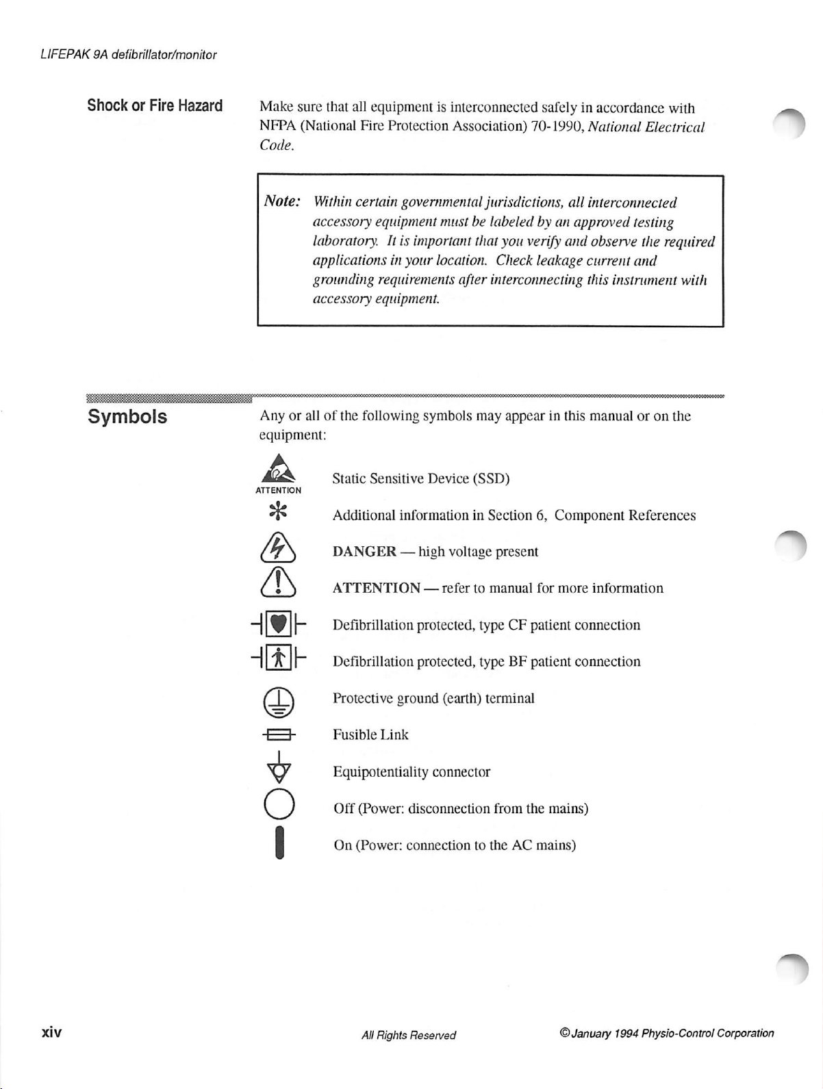
Shock
Symbols
or
Fire
Hazard
Make
sure
NFPA
(National
Code.
Note:
Any
or
all
equipment:
À
ATTENTION
that
all
equipment
Fire
Protection
Within
accessory
laboratory.
applications
grounding
accessory
of
the
Static
certain
equipment
It
in
requirements
equipment.
following
Sensitive
is
interconnected
Association)
governmental
must
be
is
important
your
symbols
Device
that
location.
after
may
(SSD)
safely
70-1990,
jurisdictions,
labeled
you
Check
interconnecting
appear
by an
verify
leakage
in
all
approved
and
this
in
accordance
National
interconnected
observe
current
this
manual
Electrical
testing
the
required
and
instrument
or
on
with
with
the
Additional
*
DANGER
ATTENTION
PB
LL
ta
|S
>|
Defibrillation
Defibrillation
TT
Protective
Fusible
Equipotentiality
Off
(Power:
On
-O<+ie
(Power:
information
—
high
—
protected,
protected,
ground
Link
disconnection
connection
in
Section
voltage
refer
to
manual
type
type
(earth)
connector
terminal
to
present
CF
BF
from
the
the
AC
6,
Component
for
more
patient
patient
connection
connection
mains)
mains)
References
information
xiv
All
Rights
Reserved
©
January
1994
Physio-Control
Corporation
Page 15
General
Information
ervice
Information
Before
technician
Service and
If
technician
in
operating
required, a qualified
Procedure
adjustments
appropriate
Use
adapter
For
1-800-442-1142.
representative.
attempting
should
Maintenance.
the
instrument
should
Section
3,
beginning
within
(TCP)
must
training
of
non-Physio-Control
devices
assistance
in
be
has
complete
specifications.
be
may
servicing
In
to
clean
or
familiar
been
dropped,
on
page
technician
in
Section
performed
and
experience.
void
Safety
the
other
countries
repair
any
assembly
with
the
information
damaged,
the
Performance
3-1,
to
confirm
If
calibration
can
perform
3.
Component
only
by
service
defibrillation
Agency
instrument
contact
in
this
provided
or
abused, a qualified
Inspection
whether
or
more
extensive
the
Test
and
replacement
personnel
electrodes,
Certifications
in
the
the
batteries,
and
US,
call
local
Physio-Control
instrument,
in
Procedure
the
instrument
Calibration
and
internal
qualified
warranty.
Physio-Control
the
Section
4,
(PIP)
is
testing
accessories,
is
by
or
at
-
January
1994
Physio-Control
Corporation
All
Rights
Reserved
Page 16

LIFEPAK
9A
defibrillator/monitor
Effective
Publication
Dates
The
effective
Title
Trademark
Table
List
List
publication
and
Warranty
of
Contents
of
Figures
of
Tables xi
date
for
each
Page
ii
iii
viii
page
thru
thru
of
this
manual
vii
ix
is
listed
January
January
January
January
below.
Date
1994
1994
1994
1994
Safety
Information
Terms
Warnings
Symbols
General
1
2
3
4
5
6
Information
Service
Effective
Configuration
Content
Description
Operation
Testing
Service
Part
Lists/Schematics
Component
Publication
Information
Overview
and
Maintenance
Reference
Dates
xii
xii
xiii
xiv
ху
XV
xvi
xvii
xviii
1-1
2-1
3-1
4-1
5-1
6-1
thru:
thru
thru
thru
thru
thru
thru
thru
xiv
xviii
1-35
2-10
340
4-16
5-87
6-16
January
January
January
January
January
January
January
January
January
January
January
January
January
January
January
1994
1994
1994
1994
1994
1994
1994
1994
1994
1994
1994
1994
1994
1994
1994
xvi
Index
All
Rights
Reserved
Index-1
thru
Index-6
January
©
January
Physio—Control
1994
1994
Corporation
Page 17

e
Configuration
Information
Assembly
LIFEPAK
Main
PCB
Power
Power
Interconnect
Keypad
Rear
Panel
Strip
Chart
Transfer Relay
Paddle
Display
Power
Power
Battery
High
Voltage
Main
PCB/Monitor
Main
PCB/Recorder
Interconnect
Main
PCB/Patient
AC
Receptacle/Ground
AC
Receptacle
Test
Load
Power
Power
Power
Power
Main
PCB/Sternum
Main
PCB/Apex
Storage
Storage
Recorder/Bracket
Power
Name
9A
defibrillator/monitor
Assembly
Supply
Conversion
Supply
Conversion
Conversion
Conversion
Conversion
Conversion
Supply
PCB
PCB
Assembly
Assembly
Switch
Recorder
Assembly
Assembly
PCB/CRT
PCB/AC
Sensor/Power
Connector
PCB/Keypad
Wire
Contact/Resistor
Relay
Capacitor
Capacitor
Gound
Bracket/Ground
This
manual
numbers.
Assembly
PCB
Assembly
Membrane
Assembly
Assembly
Receptacle/Ground
PCB/Power
Supply
PCB
Cable
Connector
Wire
Harness
PCB/Reed
PCB/Dump
PCB/Charge
PCB/Charge
Relay
Wire
Positive/Relay
Negative/Relay
SupplyPCB/Battery
PCB
Cable
Assembly
Cable
Assembly
Assembly
Cable
Assembly
Wire
Harness
(W
10)
Wire
Harness
Assembly
Relay
Relay
Relay
Wire
Harness
Harness
Wire
Wire
Wire
Harness
Wire
is
The
Wire
Harness
(W4)
(W5)
(W6)
Harness
(W9)
(W11)
Wire
Wire
Negative
Positive
(W16)
(W17)
Harness
Harness
(W21)
Harness
current
with
assemblies
Wire
Harness
Wire
(W3)
(W7)
(W8)
Harness
Harness
Wire
Wire
(W13)
Harness
(W18)
(W19)
(W22)
the
appear
(W1)
Harness
(W12)
Harness
listed
in
(W2)
(W14)
(W15)
revision
the
same
level
of
the
order
as
in
PartNumber
803800
803715-11
803726-01
803724-03
803761-02
803771
803741-01
804189-00
800240-14
802901-06
803706
803783-30
803783-23
803783-24
803756-13
803733-00
803773-00
803772-00
803783-00
803783-04
803783-05
803783-06
803783-07
803783-08
803783-09
803783-10
803783-11
803783-12
803783-13
803783-14
803783-19
803783-29
following
Table
5-1.
part
Rev
H4
C3
Orig7
D6
C4
C3
Al
B2
U10
F
AS
BS
BS
BS
D4
0081
Orig]
Orig3
BS
BS
BS
BS
BS
BS
BS
BS
BS
BS
BS
BS
BS
BS
©
January
1994
Physio-Control
Corporation
All
Rights
Reserved
xvii
Page 18
LIFEPAK
9A
defibrillator/monitor
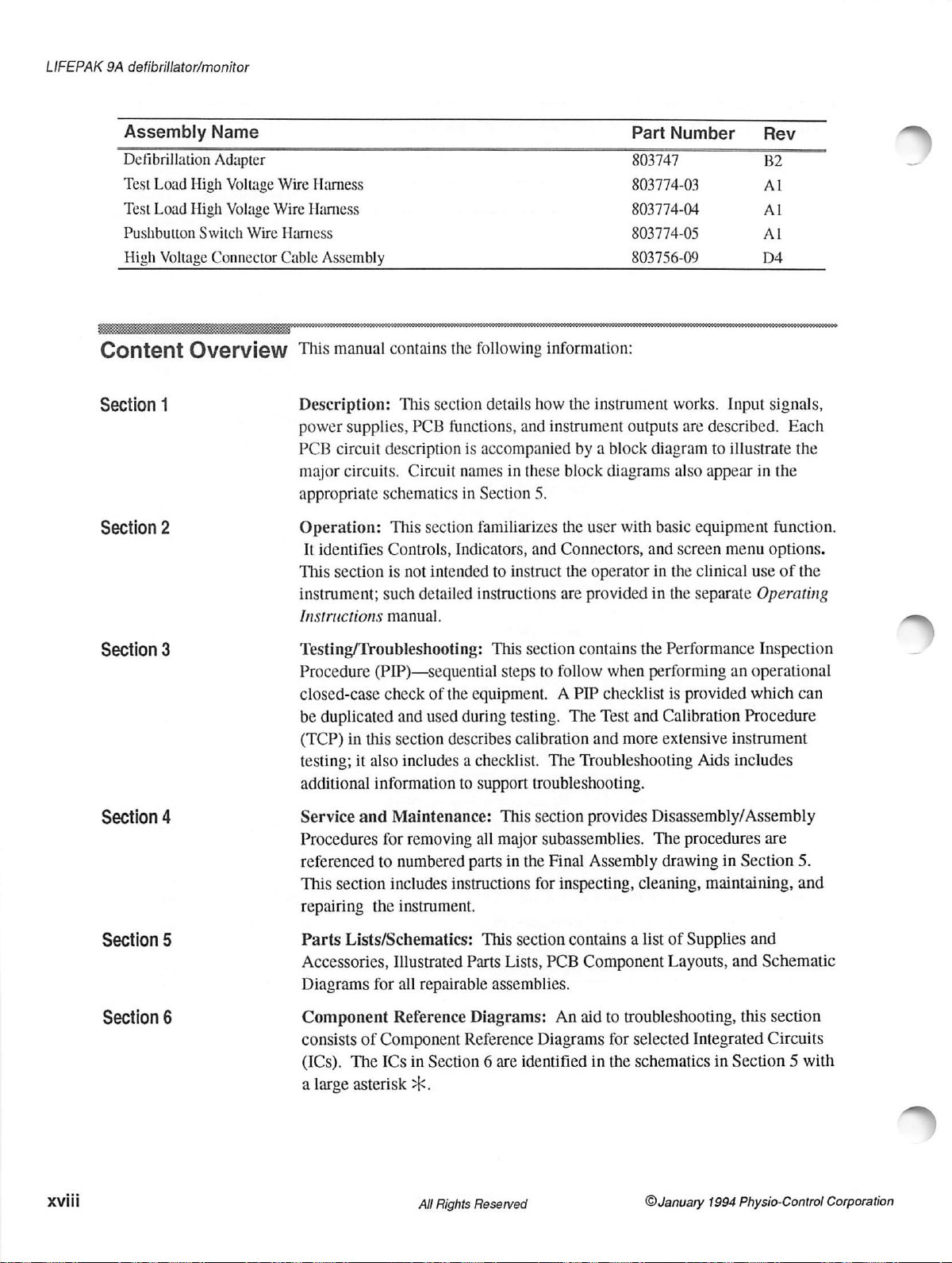
Assembly
Defibrillation
Test
Load
Test
Load
Pushbutton
High
Voltage
Content
Name
Adapter
High
High
Switch
Connector
Overview
Voltage
Volage
Wire
Wire
Wire
Harness
Harness
Harness
Cable
Assembly
This
manual
contains
the
following
PartNumber
803747
803774-03
803774-04
803774-05
803756-09
information:
Rev
B2
Al
Al
Al
D4
Section
Section
Section
Section
1
2
3
4
Description:
power
supplies,
PCB
circuit
major
circuits.
appropriate
Operation:
It
identifies
This
section
instrument;
Instructions
This
section
PCB
functions,
description
Circuit
schematics
This
Controls,
is
not
such
detailed
is
names
in
section
Indicators,
intended
manual.
accompanied
Section
familiarizes
instructions
Testing/Troubleshooting:
Procedure
closed-case
be
duplicated
(TCP)
testing;
additional
Service
Procedures
referenced
This
repairing
(PIP)—sequential
check
and
in
this
section
it
also
includes a checklist.
information
and
Maintenance:
for
removing
to
numbered
section
includes
the
instrument.
of
the
equipment. A PIP
used
during
describes
to
support
all
parts
instructions
details
and
in
these
how
instrument
5.
and
Connectors,
to
instruct
are
This
section
steps
to
follow
testing.
calibration
The
troubleshooting.
This
section
major
subassemblies.
in
the
Final
for
inspecting,
the
instrument
outputs
by a block
block
the
user
diagram
diagrams
with
basic
and
the
operator
provided
contains
when
in
in
the
performing
checklist
The
Test
and
and
more
Troubleshooting
provides
Disassembly/Assembly
The
Assembly
cleaning,
works.
also
Input
are
described.
to
illustrate
appear
equipment
screen
menu
the
clinical
the
separate
Performance
an
is
provided
Calibration
extensive
procedures
drawing
instrument
Aids
includes
in
Section
maintaining,
signals,
Each
the
in
the
function.
options.
use
of the
Operating
Inspection
operational
which
Procedure
can
are
5.
and
xviii
Section
Section
5
6
Parts
Lists/Schematics:
Accessories,
Diagrams
for
Component
consists
(ICs).
a
The
large
of
Component
ICs
asterisk
Illustrated
all
Reference
Parts
repairable
Diagrams:
Reference
in
Section 6 are
>k.
Alll
Rights
Reserved
This
section
Lists,
PCB
assemblies.
Diagrams
identified
contains a list
Component
An
aid
to
troubleshooting,
for
selected
in
the
schematics
of
Supplies
Layouts,
Integrated
©January
and
and
Schematic
this
section
Circuits
in
Section 5 with
1994
Physio-Control
Corporation
Page 19
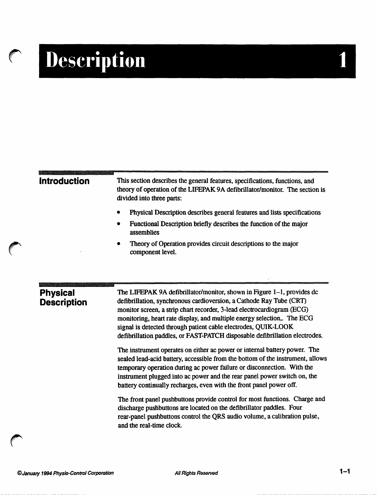
Description
Introduction
This
theory
divided
e
e
e
Physical
Description
The
defibrillation,
monitor
monitoring,
signal
defibrillation
The
sealed
temporary
instrument
battery
section
Physical
Functional
assemblies
Theory
component
LIFEPAK
describes
of
operation
into
three
Description
of
Operation
9A
synchronous
screen, a strip
heart
is
detected
paddles,
instrument
lead-acid
operation
plugged
continually
the
general
of
the
LIFEPAK
parts:
describes
Description
provides
level.
features,
briefly
describes
circuit
9A
general
defibrillator/monitor,
cardioversion, a Cathode
chart
rate
display,
through
or
operates
battery,
during
into
recharges,
recorder,
and
patient
FAST-PATCH
on
either
accessible
ac
power
ac
power
even
3-lead
multiple
cable
electrodes,
ac
power
from
failure
and
the
with
specifications,
defibrillator/monitor.
features
the
function
descriptions
shown
in
Figure
electrocardiogram
energy
selection,.
and
to
Ray
lists
of
the
1-1,
Tube
functions,
The
specifications
the
major
major
provides
(CRT)
(ECG)
The
QUIK-LOOK
disposable
or
the
rear
the
front
defibrillation
internal
bottom
or
disconnection.
panel
battery
of
the
power
panel
power
electrodes.
power.
instrument,
With
switch
on,
off.
and
section
is
dc
ECG
The
allows
the
the
©January
1994
Physio-Control
Corporation
The
front
panel
discharge
rear-panel
and
pushbuttons
pushbuttons
the
real-time
pushbuttons
are
located
control
clock.
Rights
All
provide
on
the
QRS
Reserved
control
the
for
defibrillator
audio
volume, a calibration
most
functions.
paddles.
Four
Charge
pulse,
and
1-1
Page 20
LIFEPAK
9A
defibrillator/monitor
PHYSIO-CONTROL
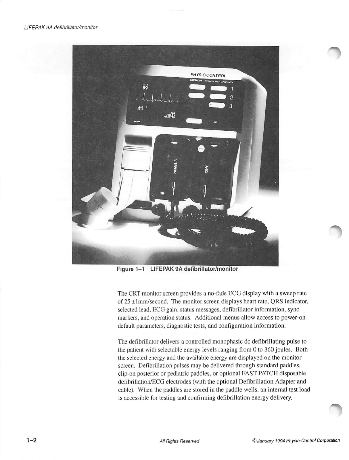
Figure
The
of
selected
markers,
default
The
the
the
screen.
clip-on
defibrillation/ECG
1-1
CRT
monitor
25
+Imm/second.
lead,
and
parameters,
defibrillator
patient
selected
Defibrillation
posterior
cable).
is
When
accessible
LIFEPAK
ECG
operation
with
energy
the
for
9A
screen
The
gain,
status.
diagnostic
delivers a controlled
selectable
and
the
pulses
or
pediatric
electrodes
paddles
testing
and
defibrillator/monitor
provides a no-fade
monitor
status
energy
available
are
screen
messages,
Additional
tests,
and
levels
energy
may
be
delivered
paddles,
(with
the
stored
in
confirming
ECG
displays
defibrillator
menus
configuration
monophasic
ranging
are
or
optional
optional
the
paddle
defibrillation
display
heart
allow access
dc
from
displayed
through
FAST-PATCH
Defibrillation
wells,
with a sweep
rate,
information,
information.
defibrillating
0 to
360
on
standard
an
internal
energy
QRS
indicator,
sync
to
power-on
pulse
joules.
the
monitor
paddles,
disposable
Adapter
test
delivery.
rate
>
to
Both
and
load
All
Rights
Reserved
©January
1994
Physio-Control
Corporation
Page 21

The
recorder
heart
rate,
The
ac
panel.
Table
and
line
The
1-1.
can
print
SYNC
power
fuses
LIFEPAK
the
ECG
trace,
time
(if
activated).
and a ground
9A
defibrillator/monitor
connector
and
date,
ECG
are
accessible
specifications
lead
at
are
and
size,
the
listed
Description
rear
in
1
ECG
Monitor
ECG
LEAD
INPUT
PATIENT
COMMON
CABLE
MONITOR
SWEEP
FREQUENCY
ECG
HEART
1
mV
SPEED
ECG
Leads:
Paddles:
SIZE
RATE
Cal
Defibrillator
ENERGY
External
Internal
CHARGE
PADDLE
CHARGE
CORD
Table
SELECTIONS
LENGTH
MODE
DISPLAY
SELECT
Paddles:
Paddles:
CONTROLS
INDICATORS
REJECTION
RESPONSE
METER
LENGTH
1-1
SIZE
LIFEPAK
9A
defibrillator/monitor
Std,
Paddles,
Isolated
disposable
Total
length
100dB
with
respect
mode
range
ground.
102mm
I,
II,
ECG
via
defibrillation/ECG
4.0m
minimum
to
isolated
for
patient
(4in)
wide x 76mm
25mm/s
Non-diagnostic.
1.0
to
40Hz
(-3dB)
2.2
to
20Hz
(-3dB)
Adjusts
Three-digit
outside
Momentary
the
1,
1,
Independent
ECG
2,
2,
3,
3,
4,
4,
amplitude
readout
this
range
pushbutton
input.
5,
6, 7, 8,
5,
6, 7,
momentary
paddle.
3m
(10ft)
Flashing
increasing
progress.
completed
lamps
stored
Upon
tone
on
sounds.
HI.
QUIK-LOOK
(13ft):
with
cable
respect
ground
cable
of
ECG
displays
do
not
yield
on
9,
10,
20,
8,9,
10,
20,
pushbutton
paddle
energy
full
and
display
charge,
Specifications*
defibrillator
electrodes,
3.1m
(10ft),
to
chassis
when
measured
input
210V
(3in)
tall,
non-fade.
trace
on
monitor
rates
from
20
valid
systole
rear
panel
simulates a 1mV
30,
50,
100,
30,
501
controls
front
panel
on
monitor
energy
available
paddles,
or
3-lead
leads
ground
and
at
peak
with
and
strip
to
300bpm.
tones
200, 300,
on
front
pushbutton
indicate
is
displayed
FAST-PATCH
patient
0.9m
(3ft).
65dB
60Hz.
Common
respect
chart
Heart
or
heart
signal
360J
panel
along
charge
cable.
minimum
to
isolated
recorder.
rates
rate
display.
pulse
to
and
APEX
with
in
and
charge
©January
-*AIl
specifications
1994
Physio-Control
at
20°C
Corporation
unless
otherwise
stated.
Specifications
All
Rights
Reserved
subject
to
1-3
Page 22

LIFEPAK
9A
defibrillator/monitor
Table
Defibrillator
CHARGE
SYNC
SYNC
DEFIBRILLATOR
ACCURACY
DEFIBRILLATOR
Itamps)
INDICATOR
60
50
40
30
20
10
0 2
1-1
(cont.)
TIME
]
LA
|
|
50
Ohm
Load
LIFEPAK
ENERGY
WAVEFORM
へ
N
OA
4
DC
MAJ
6
Defibrillator
9A
Charge
Synchronizes
Inverted
synchronizer
+
+30%
5ms
50
Ohm
Load
8
10
Output
12
Waveform
defibrillator/monitor
to
360J
in
less
than
10s
triangle
15%
at
500
over
monophasic
360
Joule
T
{msec}
14
defibrillator
marker
trigger
the
range
pulse
Itemps)
pulse
on
point
with
of
25
(Edmark)
80
70
;
50
40
30
20
10
displayed
to
Specifications*
with a fully-charged
to
patient-generated
ECG
waveform
respect
10002
to
patient’s
25
(cont.)
battery.
QRS
complex.
identifies
QRS
complex.
Ohm
Load
360
Joule
I
(amps)
Thermal
PAPER
Size:
Speed:
DELAY
FREQUENCY
ECG
ECG
Paddles:
ANNOTATION
40
30
20
10
0 2 4
100
Array
Leads
Leads
6
8
Ohm
Load
DC
Defibrillator
10
Output
Waveform
Recorder
RESPONSE
(non-diagnostic):
(diagnostic):
Ohm
Load
360
100
12
50mm
25mm/s
ECG
Non-diagnostic
Time,
Joule
14
16
wide x 30m
prints 8 seconds
1.0
to
40Hz
0.05
to
2.2
to
20Hz
date,
T
(msec)
18
(diagnostic
(-3dB).
100Hz
(-3dB).
ECG
—10
(100ft)
after
(-3dB).
lead,
ECG
0
0 2 4 6 8
25
Ohm
Load
DC
Defibrillator
first
appearing
available
gain,
heart
via
rate,
on
Setup
10
12 14
Output
Waveform
the
monitor.
Menu).
defibrillation
parameters,
T
(msec)
|
)
1-4
All
Rights
Reserved
©January
1994
Physio-Control
Corporation
Page 23
Description
1
General
AC
INPUT
BATTERY
BATTERY
LOW
BATTERY
BATTERY
SERVICE
POWER
SIZE
Height:
Width:
Depth:
Weight:
POWER
STANDARD
ELECTRODE
Table
OPTIONS
TYPE
CAPACITY
BATTERY
CHARGE
CHARGE
INDICATOR
CONSUMPTION
CORD
LENGTH
PADDLE
AREA
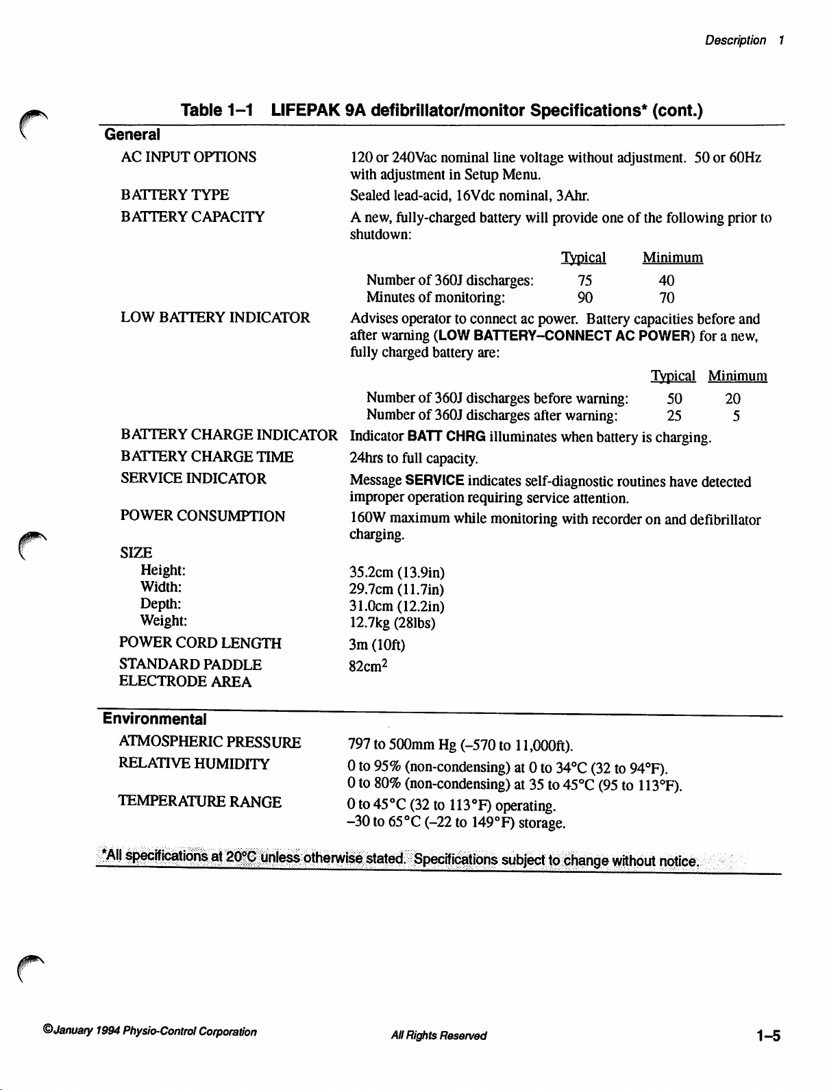
1-1
INDICATOR
LIFEPAK
INDICATOR
TIME
9A
defibrillator/monitor
120
or
240Vac
with
adjustment
Sealed
A
shutdown:
lead-acid,
new,
fully-charged
Number
Minutes
Advises
after
warning
fully
charged
Number
Number
Indicator
24hrs
to
Message
improper
160W
maximum
charging.
35.2cm
29.7cm
31.0cm
12.7kg
3m
(13.9in)
(11.7in)
(12.2in)
(281bs)
(10ft)
nominal
in
of
360J
of
monitoring:
operator
(LOW
battery
of
360J
of
360J
BATT
CHRG
full
capacity.
SERVICE
operation
Setup
16Vdc
battery
discharges:
to
connect
BATTERY-CONNECT
are:
discharges
discharges
illuminates
indicates
requiring
while
82cm?
Specifications*
line
voltage
Menu.
nominal, 3 Ahr.
will
ac
self-diagnostic
monitoring
without
provide
Typical
power.
before
after
warning:
when
service
with
attention.
adjustment.
one
of
75
90
Battery
AC
warning:
battery
routines
recorder
(cont.)
50
the
following
Minimum
40
70
capacities
POWER)
is
charging.
on
before
50
25
have
and
defibrillator
or
60Hz
prior
and
for a new,
20
5
detected
to
©January
Environmental
ATMOSPHERIC
RELATIVE
TEMPERATURE
1994
Physio-Control
PRESSURE
HUMIDITY
RANGE
Corporation
797
0
to
O
to
0
to
—30
to
500mm
95%
80%
45°C
to
65°C
All
Hg
(non-condensing)
(non-condensing)
(32
to
(-22
Rights
Reserved
(-570
113°F)
to
149°F)
to
11,000ft).
at
0
to
34°C
at
35
to
45°C
operating.
storage.
(32
(95
to
94°F).
to
113°F).
1-5
Page 24

LIFEPAK
9A
defibrillator/monitor
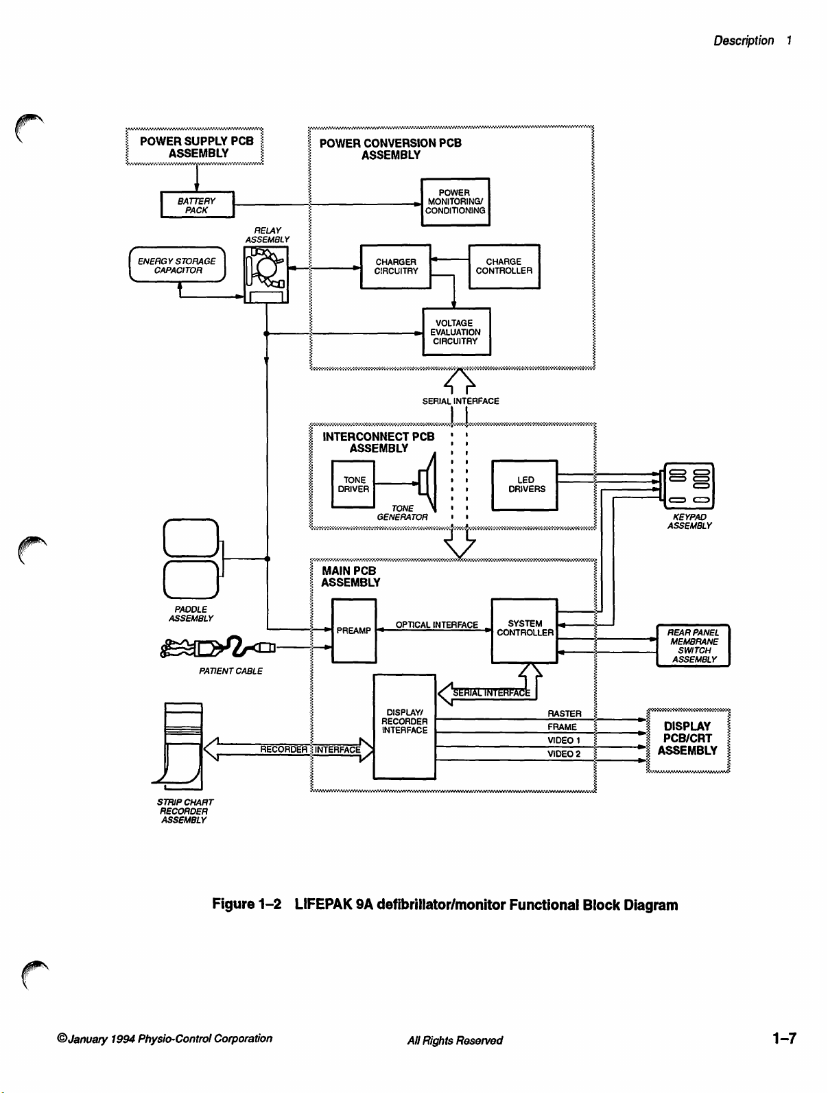
Functional
Description
The
overall
Figure
(Keypad,
Relay,
assemblies
function
1-2.
The
Rear
Paddles,
(Power
Display).
The
Keypad
input.
The
Strip
Transfer
Battery
The
90Vac
Power
supplied
The
power
Relay
Pack
Power
to
270Vac
Supply
to
Power
on/off
Supply
the
Conversion
defibrillation
present
on
the
of
the
LIFEPAK
defibrillator/monitor
Panel
Membrane
and
Battery
Supply,
and
Rear
Chart
and
Paddle
provides
PCB
at
50Hz
PCB
converts
Power
switching,
charging,
Power
Pack)
Power
Panel
Membrane
Recorder
Assemblies
temporary
functions
or
60Hz
the
Conversion
PCB
performs a variety
generation
and
stored
Conversion
9A
defibrillator/monitor
includes
Switch,
and
Strip
five
Printed
Conversion,
Switch
Assembly
help
backup
over
ac
power.
the
without
line
power
full
input
PCB.
of
additional
energy
transfer. A test
PCB.
six
mechanical
Chart
Recorder,
Circuit
Interconnect,
Assemblies
provides
deliver
printed
defibrillator
range
of
line
voltage
to
the
nominal
of
power-handling
power
Board
Main,
receive
output.
input
voltages
selection.
+18.4Vdc
supply
load
is
shown
in
assemblies
Transfer
(PCB)
and
operator
The
pulses.
The
from
The
functions:
voltages,
circuit
is
also
人
The
Interconnect
PCB
and
the
Power
the
audible
The
Main
Controller,
from
System
detection,
implemented
System
microprocessor
tones
PCB
has
and
the
both
the
3-lead
Controller
rate
calculation,
the
in
microprocessor
to
Display/Recorder
messages
The
5-inch
deflection
produce
and
Display
diagonal
and
raster
a
recorder
PCB/CRT
Cathode
incorporates
scan.
PCB
provides
Conversion
and
to
drive
three
the
major
the
PCB.
sections
Display/Recorder
patient
directs
System
the
cable
overall
the
and
synchronous
Controller
ECG
the
and
Display/Recorder
microprocessor
annotations.
Assembly
Tube
Ray
vertical
electrical
It
also
front
panel
of
circuitry:
Interface.
and
QUIK-LOOK
operation
software.
are
data
microprocessor,
and
select
to
contains
a
(CRT).
horizontal
and
connection
contains
between
circuitry
LEDs.
the
Preamp,
The
Preamp
paddles
other
the
of
cardioversion
current
The
transmitted
allowing
format
Monitor
uses
It
the
PCB
electromagnetic
deflection
the
to
produce
the
System
receives
inputs.
all
the
QRS
of
System
circuits.
are
state
from
the
appropriate
drives
that
beam
circuitry
Main
|
input
The
the
CRT
the
to
1-6
All
Rights
Reserved
January
©
Physio-Control
1994
Corporation
Page 25
Description
1
(
POWER
ENERGY
SUPPLY
ASSEMBLY
|
BATTERY
PACK
STORAGE
CAPACITOR
PCB
ASSEMBLY
IO
È
|
RELAY
É
POWER
CONVERSION
PCB
ASSEMBLY
POWER
#1
i
더
È
CHARGER
CIRCUITRY
i
Vo
INTERCONNECT
ASSEMBLY
TONE
DRIVER
M
GENERATOR , ,
CONDITIONING
«@
TT
SERIAL
PCB ' '
ТОМЕ
MONITORING/
VOLTAGE
EVALUATION
CIRCUITAY
INTERFACE
na
1a
t
|
CONTROLLER
+
os
CHARGE
LED
DRIVERS
<
μα
Ч > o
KEYPAD
ASSEMBLY
=
PADDLE
ASSEMBLY
PATIENT
STRIP
CHART
RECORDER
ASSEMBLY
く
_
Figure
|
CABLE
RECORDER:INTERFACE
1-2
é
:
i»
LİFEPAK
MAIN
PCB
ASSEMBLY
>]
РАЕАМР
9A
OPTICAL
DISPLAY?
INTERFACE
INTERFACE
N
defibrillator/monitor
INTERFACE
#1
SYSTEM
CONTROLLER
|
RASTER
FRAME
VIDEO
VIDEO
Functional
1
2
E
—
_
i
DISPLAY
“É
PCB/CRT
>
ASSEMBLY
REAR
MEMBRANE
SWITCH
ASSEMBLY
Block
Diagram
PANEL
©January
1994
Physio-Control
Corporation
All
Rights
Reserved
1-7
Page 26
LIFEPAK
9A
defibrillator/monitor
Theory
of
Operation
Power
Assembly
Supply
(803726)
PCB
This
section
Power
PCB/CRT
circuits
selected
in
Section
The
Power
the
Power
contains
Conversion
Assemblies.
in
Section 5 while
integrated
6.
Supply
Conversion
detailed
PCB,
Interconnect
Refer
reading
circuits
PCB
(indicated
converts
PCB
circuit
to
schematic
and
for
descriptions
PCB,
the
circuit
by a *K
input
ac
voltage
charging
of
the
Main
PCB,
diagrams
of
descriptions.
on
the
schematic)
to a nominal
the
battery.
Power
and
these
Supply
Display
electrical
Information
is
dc
PCB,
about
provided
voltage
for
Power-On
Regulation
Overvoltage
Protection
When
ac
current
CRI.
Resistor
and
R12
turn
and
is
coupled
into
QI,
causing
Increasing
Q2
and a voltage
overrides
base
When
and
current
current
Q1
drive
current
battery
couples
subsides
regulation.
If
the
regulation
together
CR13
short
protection
with
sets
the
a
Power
circuit.
flows
divider
on
QI.
with
pins | and
saturation.
through
drop
and
terminates
to
voltage
the
voltage
to
proper
circuit
CR13,
voltage
Supply
through
R1, R3,
Current
builds
the
across
parallel
the
Q2.
exceeds
from
T2
levels,
fails,
Silicon
R17,
and
threshold
circuit
PCB
J1,
it
is
conditioned
and
R4
in
series
in
Tl
primary
2.
Capacitor
Tl
primary
produces
resistors
primary
the
current.
voltage
threshold
pins 4 and 5 to
Q4
turns
Controlled
R18,
protects
which,
when
output.
with
windings
C6
couples
R11
Transformer
T2
off,
providing
Rectifier
the
load
exceeded,
Removing
by
RT1,
L1,
parallel
the
current
voltage
and
set
R12.
by
VRI,
on
pins 2 and
current
(SCR)
from
damage.
triggers
power
ac
C2,
C3, and
resistors
R11
(pins 4 and
build-up
the
base
Q2
activation
T2
sustains
Q4
turns
7.
When
feedback
CR12,
Diode
CRI2
SCR
resets
6)
of
on
for
to
the
Output
Battery
Isolation
CR11
Diode
from
protect
necessary
it
because
PCB.
16Vdc,
The
output.
The
instrument
the
As
on.
voltage
mode.
isolates
battery
the
the
lead-acid
battery
connected
is
battery
approaches
Current
All
Rights
Power
the
voltage
battery
battery
receives
ac
to
limiting
Reserved
Supply
when
connected
is
wired
is
constant
a
power
charge,
full
sets
PCB
power
ac
in
directly
charging
the
and
the
maximum
the
output
from
is
parallel
the
to
current
panel
rear
supply
charge
the
removed.
the
with
Power
Supply
whenever
mains
operates
current
©January
network
filter
This
Power
power
constant
in
available
1994
to
is
Supply
PCB
the
switch
is
to
Physio-Control
Corporation
Page 27
CHRG
BATT
Power
PCB
Conversion
Assembly
(803724)
Power
Control
Indicator
approximately
battery
the
Power
charging
battery-charging
A
indicator
panel
indicator
the
The
additional
charging,
The
control
Control
Control
Charger
at
Supply
severely
a
whenever
mains
Power
Conversion
voltage
and
Power
Control
instrument
circuit
Input,
circuits.
PCB
power
from
defibrillation
are:
Low
+4.5A.
sources
depleted
LED
the
switch
lighting
generation
current
battery.
signal
power
ac
on.
is
if
PCB
illuminates
the
contains
and
energy
circuit
operation.
regulates
Switching
Energy
Charge
The
Power
limit
This
dead
a
into
the
connected
is
interlock
An
not
battery
is
circuitry
monitoring,
transfer.
battery
circuits
Rate,
Refer
voltage
directly
Supply,
and
Energy
implemented
is
requirement
a
short,
panel
front
instrument
the
to
battery
the
in
installed.
power
for
energy
Logic
storage
to
Figure
for
the
affected
Power
Storage
when
CHRG
BATT
and
harness
switching,
on/off
capacitor
1-3,
circuits
by
the
Monitor,
Capacitor
the
when
the
prevents
page
which
Power
External
Description
rear
1-10.
1
The
Front
Panel
the
Power
power
which
gate
PWR
SWBATT
circuits.
When
V
BATT
the
PWR
low-to-high
disabling
Control
connector:
of
Q11).
Control
on), V BATT
in
turn
of
Q11
SW
MONITOR
voltage
the
power
is
divided
SW
the
circuit
ON
momentary
circuit.
passes
causes
by
RS2,
for
switch
Q10
which
by
MONITOR
transition
Power
R60
Control
may
be
(connects
pushbutton
When
the
to
the
gate
to
conduct. A portion
keeps
Q10
line
is
low
and
the
rest
of
the
is
pressed a second
R108
and
R109,
line
high.
and
activates
circuit.
confirmed
to
the
the
by
gate
provides
power
of
switch
Q11,
causing
of V BATT
conducting.
the
Power
Power
Control
Conversion
time
(turning
forward-biasing
The
System
Logic
The
functional
monitoring
of
Q10)
microprocessor
Power
two
and
R57
the
start-up
is
first
pressed
Q11
to
is
During
this
circuit
PCB
power
CR44
Monitor
integrity
pins
on
(connects
signal
(turning
conduct,
held
on
time
the
provides
Assembly
off),
and
switching
reads
circuit,
of
the
Power
the
test
to
the
for
the
the
the
gate
©January
1994
Physio-Control
Corporation
All
Rights
Reserved
1-9
Page 28
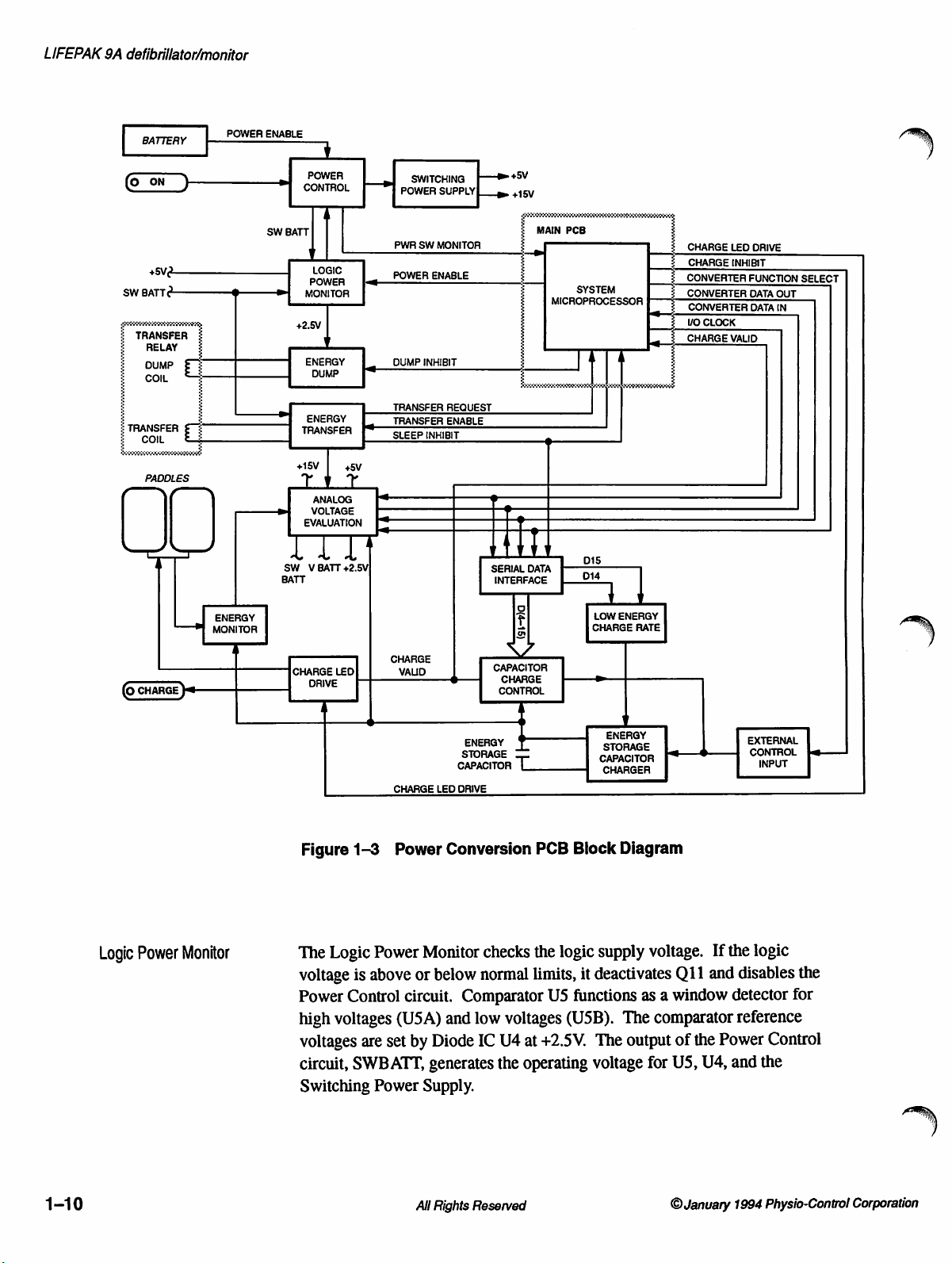
LIFEPAK
9A
defibrillator/monitor
BATTERY
*sv
SW
BATT
£
;
z
TRANSFER
RELAY
pup
COIL
5
5
TRANSFER
ὃν
PADDLES
(©
CHARGE
à
σου
§
)«
νὰ
ENERGY
MONITOR
POWER
ENABLE
POWER
CONTROL
SW
BATT
|
Ч
toc
POWER
æ]
MONITOR
+2.5V
ENERGY
DUMP
ー』
ENERGY
TRANSFER
+15V
ANALOG
si
VOLTAGE
EVALUATION
ITI
SW V BATT
BATT
CHARGE
DRIVE
4
>
ma
+5V
+2.5V
LED
Le
DUMP
|
TRANSFER
TRANSFER
SLEEP
CHARGE
SWITCHING > +5V
POWER
SUPPLYÎ
PWR
SW
MONITOR
POWER
ENABLE
INHIBIT
REQUEST
ENABLE
INHIBIT
VALID
CHARGE
LED
gm
+15V
1
HT
SERIAL
INTERFACE
=
CAPACITOR
CHARGE
CONTROL
ENERGY
STORAGE
CAPACITOR
ORIVE
一
|
|
È
DATA
ο
=
|
|
|
MAIN
PCB
MICROPROGESSOR
14 | 4
D4
D15
LOW
ENERGY
CHARGE
때
>
STORAGE
capaciToR
|
CHARGER
>
|
RATE
CHARGE
CHARGE
CONVERTER
CONVERTER
CONVERTER
VO
CLOCK
CHARGE
F—
LED
DRIVE
INHIBIT
FUNCTION
DATA
OUT
DATA
IN
VALID
EXTERNAL
CONTROL
INPUT
SELECT
Le
1-10
Logic
Power
Monitor
Figure
The
voltage
Power
high
voltages
circuit,
Switching
1-3
Logic
is
Control
voltages
are
SWBATT,
Power
Power
above
circuit.
(USA)
set
Power
Conversion
Monitor
or
below
and
by
Diode
generates
Supply.
All
Rights
PCB
checks
normal
Comparator
low
IC
Reserved
the
limits,
voltages
U4
at
the
operating
Block
logic
it
U5
functions
(USB).
+2.5V.
Diagram
supply
deactivates
The
voltage
voltage.
as a window
The
comparator
output
for
US, U4,
©
If
Q11
and
of
the
January
the
logic
disables
detector
reference
Power
Control
and
the
1994
Physio-Control
the
for
Corporation
Page 29
The
System
signal
to
the
of
USB
to
ground
Electrical
isolation
microprocessor
POWER
ENABLE
which
is
provided
turns
shuts
line.
off
by
down
This
Q11,
CR24
the
instrument
switches
disabling
and
R39.
the
by
sending a low
the
open
Power
collector
Control
circuit.
Description
output
1
Switching
Power
Supply
A time
Control
during
detector
The
check
Voltage
and
The
flyback-coupled
used
The
error
90Hz
the
frequency
V
protect
primary.
delay
circuit
initial
(USA)
low-
and
circuit
measurements
R56
(relative
Switching
by
the
pulse-width
amplifier,
by
R30
outgoing
pulse
BATT
voltage
Q12
function
from
power-on.
and
high-limit
performance
Power
other
and
and
pulse-width.
from
in
the
shutting
Capacitor
C18
for
detector
check
to
the
+5V
Supply
inductor
circuits.
regulator
C12.
by
into
high
(T2)
drive
circuitry
The
driving
the
primary
voltages
Logic
Power
down
while
operating
C26
accomplishes
the
low-limit
inputs
by
serving
the
accuracy
supply).
uses a pulse-width
to
U3
contains
+15V
The
pulse
an
N-channel
caused
to
as
test
produce
an
for
Q12.
output
output
of
T2.
by
FET
Two
Monitor
detector
the
of
the
oscillator,
feedback
circuit
voltages
(USB).
test
connector
points
at
to
voltage
+5V
Oscillation
dividers
regulator
to
+15V
reference
at
U3
pin 6 provides a constant
(Q12)
and
diodes,
leakage
inductance
prevents
are
still
this
for
the
high-limit
are
used
measure
U3
CR28
voltage.
R41,
(U3)
and
supply
voltages,
frequency
pin 2 determines
dumping
and
CR29,
from
the
Power
rising
to
R42, R43,
a
voltages
an
is
set
at
the
the
External
Energy
Control
Storage
Charger
Input
Capacitor
The
Energy
N-channel
forward-biasing
System
energy
voltage,
+5V
minimum.
The
Energy
charge
the
circuit
05-07,
Amplitude
primary
controlled
Charge
+2.5V
to
the
Storage
MOSFET,
microprocessor
storage
the
Capacitor
turning
Storage
energy
consists
and
C17.
O9
comparators
of
Tl.
The
by
the
Control
circuits.
reference
primary
of
Capacitor
Q9.
for
Q9
whenever
on
off.
Capacitor
storage
of
the
U2A
input
External
at
UZA
T1.
Charger
Two
resistors
the
Main
by
setting
The
inverting
Charger
capacitor
following
and
to
the
energy
Control,
If
any
of
pin
3,
the
circuit
(R58
power
is
applied
PCB
initiates a charge
the
CHARGE
input
circuit
through
components:
U2B
determine
storage
Low
Energy
these
incoming
output
switches
is
externally
and
R59)
to
the
INHIBIT
of
U2A
rises
uses a flyback
the
Transfer
T1,
U2A
the
drive
capacitor
Charge
signals
high,
controlled
provide
instrument.
cycle
for
line
at
low
to
the
required
transformer
Relay.
at
Rate,
inhibiting
and
pulse
UZA
and
fall
below
The
U2B,
for
pin 2 is
Capacitor
the
by
The
the
core
O1,
the
the
drive
the
to
of
02,
©
January
1994
Physio-Control
Corporation
All
Rights
Reserved
1-11
Page 30
LIFEPAK
9A
defibrillator/monitor
Low
Energy
Charge
Rate
Once a charge
simultaneously
conducts,
provided
C17
is
zero.
C17.
When
low,
forcing
and
by
cycle
performs
Q7
Q7,
U2B,
When
the
voltage
U2A
T1.
The
power
function
handling
The
secondary
storage
potentials
limits
circuit-response
This
battery
a
low
the
charge
power
charge
capacitor
circuit
circuit
as
push-pull
for
the
capacitor
of
up
the
single
circuit
is
voltage
battery
rate
reguired
energy
will
to
detect
drive
winding
to
pulse
time
centered
levels,
voltage
for the
for
setting
not
the
initiates
shuts
Q7
output
to
the
drivers,
for
defibrillation.
+4.5kV
for
at
two
off.
Timing
C17,
and
shuts
off,
at
C17
high
primary
pulse.
of
T1
under
voltage
control
separate
and
and
supplies
rise
around
or
when
is
detected,
energy
charging.
is
charge
energy
storage
Similarly,
selected,
too
guickly
level.
U2A
pin
functions:
for
R23.
While
the
voltage
exceeds
preventing
of
TI
consists
Q1
and
the
The
normal
to
about
of
the
output
op
amp
U17A
an
energy
the
Low
capacitor,
thereby
for
2,
the
active
transformer
the
transformer
Q7
conducts,
at
SWBATT
+2.5V,
current
Q2
provide
energy
output
the
of
is
operating
+1.5kV,
voltage.
and
level
below
Energy
thus
the
charge
making
the
Analog
low
output
drive
pulse-width
the
starts
output
two
stored
therefore
of
U2B
flow
to
the
stages:
improved
on
the
subject
conditions.
providing
is
active
only
30J
is
selected.
Charge
sure
Rate
reducing
rate
is
slowed
the
energy
Voltage
Evaluation
driver
Q5
voltage
across
charging
switches
primary
05
апд
Об
current
energy
to
Capacitor
during
low
When
circuit
the
slows
amount
when a low
storage
is
of
Cl
of
A
signal
from
determines
selected,
output
noninverting
The
signal
R23)
this
signal
current
current
storage
Storage
time
The
charging
battery
the
low
then
switches
from
and,
in
is
is
supplied
to
the
capacitor.
Capacitor
is
increased
instrument
the
levels
the
System
output
signals
input
of
U17A
turn,
the
blocked
to
primary
This
Charger
to
30
can
operate
energy
by
monitoring
microprocessor
of
U17B.
are
applied
low,
forcing
U17A
to
controls
output
of
by
CR46.
C17.
This
circuit
and
reduces
to
less
seconds.
with
storage
capacitor
the
When
to
the
CR45
+5V,
changing
the
charge
U2A.
When
reduces
slows
the
power
than
low
BATT
at
the
an
energy
inputs
of
to
reverse-bias.
the
timing
During
U17A
half
battery
is
normal
pin 1 is
the
on-time
the
rate
consumption
of
normal.
voltage
reduced.
voltage
at
energy
level
U1SD
output
circuit
charging,
driven
of
of
charge
if
Op
amp
the
inverting
reguest
of
less
from
U20.
This
pulls
of
U17A.
(U2B,
high,
U2A
which
of
the
of
the
At
360J,
the
power
U17A
register,
than
30J
The
the
C17,
and
the
effect
additional
reduces
energy
Energy
the
charge
required
detects
input
and
U20,
is
UISD
of
for
low
1-12
All
Rights
Reserved
©January
1994
Physio-Control
Corporation
Page 31

comparing
on
set
limit
inverting
functions
with
it
noninverting
the
it
input,
described
as
+2.5V
the
in
a
the
indicates
noninverting
the
at
of
input
failing
previous
battery.
exceeds
U17A
The
paragraph.
input.
the
output
When
BATT
of
the
voltage
U17A
Description
threshold
the
on
then
1
Capacitor
Charge
Control
Capacitor
The
Charger.
capacitor
microprocessor.
comparators
Op
amp
capacitor
voltage
Storage
To
set
the
converter
U17B.
word
by
voltage
divided
U17B
rises
Comparator
Charger
above
+2.5V,
of
U2A
Charge
achieves
It
and
reports
U8A,
U17B
sets
by
controlling
is
achieved,
Capacitor
gain
for a particular
U18
is
The
output
the
System
dividers
voltage
accordingly.
U8C
in
response
U8C
high,
shutting
Control
maintains
and
the
capacitor
The
main
circuit
U8B,
and
and
maintains
an
inhibit
U17B
shuts
Charger.
connected
of
the
D/A
microprocessor.
for the
is
energy
applied
provides
to
input
switches
to
switching
down
circuit
a
voltage
components
U8C.
the
signal
down
charge
between
converter
storage
the
noninverting
from
U17B.
low.
This
the
Energy
controls
selected
selected
voltage,
the
Resistors
for
voltage
status
to
pin 2 of
U2A
which
inverting
is
controlled
capacitor
the
Energy
When
low
inhibit
Storage
the
on
the
System
of
to
the
U2A.
and
by
selection
and
R4
voltage.
of
U17B,
Storage
output
Storage
energy
op
amp
energy
When a selected
the
Energy
(D/A)
the
output
function
the
Capacitor
of
U17B
switches
Charger.
Energy
the
to
consist
voltage
disables
digital-to-analog
input
R2
output
input
the
signal
Capacitor
Capacitor
storage
U17B
and
storage
of
of a 12-bit
as
When
this
gain
of
rises
the
output
Energy
Transfer
Comparators
respect
the
minimum
the
maximum
and
U8B
levels.
selected
The
Energy
Capacitor
C9, and
When
Sternum
Request
microprocessor.
microprocessor
evaluate
to
the
form
This
signal
charge
Transfer
out
through
CR4.
the
sternum
Transfer
signal
defibrillation
required
allowed
the
energy.
from
returns a Transfer
the
CHARGE
informs
circuit
the
and
and
Apex
the
If
all
charge
energy
for
in-tolerance
for
the
same
VALID
the
System
transfers
paddles.
apex
pushbuttons
Transfer
output
energy
of
transfer
stored
on
selected.
energy;
energy
signal,
microprocessor
the
energy
The
main
on
lines
UISA
which
parameters
Enable
signal
the
energy
U8B
detects
U8A
setting.
indicating
stored
circuit
the
paddles
at
J17
produce
is
sent
are
through
storage
values
detects
The
components
correct,
outputs
valid
about
in
the
are
pressed,
the
to
the
U11A
values
energy
the
energy
Transfer
System
the
capacitor
greater
less
than
from
U8A
charge
status
of
storage
are
U6,
the
System
and
U14C.
with
than
the
Q4,
©
January
1994
Physio-Control
Corporation
All
Rights
Reserved
1-13
Page 32

LIFEPAK
9A
defibrillator/monitor
The
Transfer
Transfer
transfer
and
enable
ULIA
conducting,
current
noninverting
inverting
current
The
can
are
System
components
discharges
the
remains
and
logic
Relay
to
occur
SCR
CR4
the
relay
forces
current
the
to
input
decrease
to
high
noise
jeopardize
in
transition
and
Display/Recorder
are
C35
time
that
the
low
for
any
stray
activity
Enable
drive.
with
control
drive,
U6A
low,
starts
Transfer
of
input
the
and
through
levels
the
function
from
rendered
at
the
Transfer
an
additional
current
enable.
signal
enables
The
SWBATT
minimum
this
voltage
the
signal
causing
to
flow
Relay
goes
U6A
output
R62
involved
of
one
state
inactive
input
of
Relay
to
dissipate.
and
maintains
voltage
battery
from
Q4
when
higher
switches
and
in
many
to
microprocessors
comparator
coil
period
voltage
and
direct
U14C
to
conduct.
through
current
than
high.
switching
the
transfer
types
another.
during
transfer.
is
energized.
to
allow
This
signal,
R62.
through
the
of
To
U8D
a
constant
is
stored
in
dissipation.
it
to
the
Transfer
turns
on
CR4.
With
both
To
maintain
R62
reference
turns
This
output
U6A
of
stored
defibrillation
logic
signals,
overcome
and
other
To
accomplish
and
holds
The
output
the
Transfer
Sleep
Inhibit,
current
C9,
enabling
Transistor
Relay.
The
signal
CR4
and
a
constant
increases,
causing
Q4,
low.
effect,
speed
low
of
the
to
is
used
at
this,
voltage
off
particularly
this
high
U8D
Relay
to
the
energy
Q4
To
from
O4
the
the
energy
if
the
logic
U6B
during
U8D
reopen
as
a
the
any
Energy
Dump
Sleep
Inhibit
to
U17B
Charger.
discharge
The
Energy
stored
discharged
The
internal
relay
and a power
dump
relay
When a charge
from
draining.
The
System
charged
microprocessor
the
dump
high,
turning
time-out
microprocessor
stored
also
at
OV,
Inadvertent
of
stored
Dump
in
the
energy
within
dissipation
is
held
microprocessor
for
longer
relay
on
expires
energy.
clears
the
shift
which
inhibits
deactivation
energy
circuit
one
resistor
in
is
initiated,
from
provides a safe
storage
capacitor.
minute,
of
stored
located
the
normally
the
controls
than
one
minute.
holds
the
Dump
closed.
Q3
and
During
opening
or a different
turns
Q3
off
again
registers,
the
drive
of
the
the
energy
If
the
Energy
energy
within
closed
contact
opens
Q3,
Prior
Inhibit
charging,
the
dump
energy
setting
to
close
U19
and
to
the
Energy
charge
is
inhibit
storage
current
the
Dump
the
condition
path
paddles
circuit
accomplished
Transfer
to
prevent
preventing
to
any
charge
line
low,
keeping
the
Dump
relay.
is
chosen,
the
dump
U20.
This
Storage
capacitor.
for
are
Relay
by a permanent
the
Inhibit
If
the
relay
Capacitor
will
then
unused
charged
is
activated.
with
Assembly.
the
stored
paddles
activity,
Q3
turned
line
one-minute
the
System
and
sets
all
inputs
cause
no
energy
but
not
the
dump
The
magnet.
energy
from
being
the
System
off
and
is
switched
charge
dissipate
the
1-14
Rights
All
Reserved
©January
Physio-Contro!
1994
Corporation
Page 33

Energy
Monitor
The
Energy
into
the
this
circuit
System
information
The
value
energy
the
secondary
CR10,
System
Monitor
internal
senses
microprocessor.
(e.g.,
of
the
with a current
delivers
microprocessor
circuit
test
load.
When
the
energy
The
200J
DELIVERED).
defibrillation
transformer,
with
each
transfer
the
secondary
to a specific
confirms
delivered
System
pulse
current
the
level
an
energy
to
the
microprocessor
is
acquired
T3. A proportional
pulse. A rectifier
to
C10.
delivered
of
energy
transfer
test
load
by
monitoring
bridge,
The
voltage
energy.
is
that
is
performed
and
informs
then
displays
current
CR8
is
indexed
Description
discharged
as a test,
the
the
the
delivered
is
generated
through
in
the
1
in
Serial
Data
Interface
Capacitor
of the
charge
signal.
sure
Monitor
as a noninverting
the
The
Converter
and
the
this
microprocessor.
A
low
the
set
at
P14
to
the
stored
during
through
high
failure.
C10
delivery.
energy
The
that
each
circuit
signal
processing
Serial
Data
Data
I/O
Clock
D/A
converter
common
on
the
Analog
by
I/O
Clock
enables
register
in
the
the
positive-going
U12C
at
U11C
must
FET
pulse.
FET
Q8
time
determines
Interface
Out
control
set
of
Converter
Voltage
at
8-bit
clock
low-order
route
pin 8 following a byte
start
each
Q8
is
The
gate
shorts
the
instrument
buffer,
providing
circuitry.
consists
allow
communication
data
U18,
used
serial
lines
Function
Evaluation
P14
pin
shift
registers
inputs.
location,
transitions
the
output
transfer
in
parallel
of
Q8
is
C10
when
is
ready
the
correct
high-impedance
of
four
flow.
The
with
the
for
communication
Select
circuit
6A. A high
U19
Information
and
all
of
data
on
transfer
cycle
with
with
C10
driven
the
energy
Analog
Capacitor
for
and
I/O
the
by
charge
to
deliver
level.
lines;
while
Voltage
line
at
connector
data
transfer.
on
the
Converter
U20,
on
the
other
bits
Clock.
Converter
indicates a communication
OV
for
accurate
and
resets
the
inverted
is
enabled
energy,
Op
amp
isolation
Converter
Converter
Evaluation
Charge
with
Control
the
The
allowing
Converter
are
advanced
At
the
Data
evaluation
C10
before
Charge
which
makes
the
Energy
U1A
functions
from
the
Data
In
and
Function
circuit
circuit,
System
P14
pin
7A
data
flow
Function
I/O
Data
same
In
Select
Clock
Out
one
time,
line. A logic
each
Inhibit
rest
of
Select
and
share
enables
rate
is
line
access
line
is
position
U12A
O
January
Analog
Voltage
Evaluation
1994
Physio-Control
Corporation
The
Analog
Power
digital
microprocessor.
Voltage
Conversion
code
for
evaluation
Evaluation
PCB.
An
for
All
Rights
circuit
A/D
converter,
correct
Reserved
monitors
tolerances
operating
U9,
converts
by
the
voltages
these
System
on
the
voltages
to
1-15
Page 34

LIFEPAK
9A
defibrillator/monitor
Charge
LED
Drive
Interconnect
Assembly
(803761)
PCB
The
Charge
when
the
energy
front
panel
the
drain-of
connected
energy
the
The
and
generates
The
protection
level
charge
Interconnect
the
Power
the
LED
drive
CR11.
The
Main
writing
softest)
decoder
through
the
on
U1
R4,
LED
Drive
storage
CHARGE
Q14
limits
to
the
Charge
has
been
LEDs
on
continuously.
PCB
Conversion
audible
circuitry
is
provided
PCB
System
appropriate
line
VOL1,
on
the
Interconnect
C1
through
signal
from
capacitor
LED
and
the
current
Valid
reached,
provides
PCB.
tones.
consists
by
R9,
microprocessor
binary
VOL2,
C3,
is
the
to
signal.
Q13
electrical
It
of
R21, R22,
number
and
PCB.
and
CS.
the
System
charging.
paddle
the
When
conducts.
microprocessor
Transistor Q 14
CHARGE
Paddle
LED.
the
voltage
Transistor
connection
also
drives
the
Q4,
Q5,
Q13,
R14,
C6
through
selects 1 of 8 volume
(000
for
the
VOL3.
These
Static
lines
protection
LED.
The
for
Q14
between
front
panel
R15,
C8,
and
loudest
are
is
controls Q 14
drives
Resistor
gate
of
the
selected
then
the
Main
LEDs
and
R11.
CRI
through
levels
and
111
routed
provided
to
the
R128
Q13
is
clamps
PCB
and
Static
by
for
the
3-to-8
by
R1
on
The
decoder
System
(Q1
series
either
or
The
desired
which
Q12
the
Q11
U2A
the
drive
current
microprocessor.
through
with
U2A
U2B
free-running
tone
is
conducts,
selected
switches
pin
frequency
the
drive
U1
sets
Q3
or
R8.
The
or
U2B
applies
the
frequency.
routed
to
oscillator
grounding
voltage
on
and
3.
Transistor
of
the
transducer.
to
X1.
the
voltage
The
Q7
through
center
as
determined
voltage
The
the
gate
of
U2A
to
U2B
Q12
switches
O6
then
oscillator
Op
amps
required
decoder
Q10)
tap of
the
by
to
the
piezoelectric
in
the
System
oscillator
Q11.
If
pin
3.
pin
S.
If
off,
turns
controls
U2A
and
for
the
volume
output
which
resistor
Ol1,
the
the
on,
turns
on
puts
the
corresponding
divider
012,
microprocessor
generates a square
voltage
Transistor
voltage
applying
grounding
transistors
U2B
is
and
06.
transducer,
at
the
Q6
then
at
the
the
selected
U2B
Q11,
provide
level
selected
one
of
the
routed
to
The
output
X1.
generates
wave,
gate
of
shuts
gate
of
voltage
pin
5.
Q12,
and Q6,
buffering
by
transistors
resistor
the
input
of
UZA
the
Audio
Drive,
Q11
is
low,
off,
applying
Q11
is
high,
to
Therefore,
which
and
high
the
in
of
>
1-16
All
Rights
Reserved
©
January
1994
Physio-Control
Corporation
Page 35

PCB
Main
(803715)
Assembly
Assembly,
PCB
Main
The
Preamp,
circuits:
Interface.
sampled
System
The
System
instrument
recorder
microprocessor.
The
circuit
the
Preamp
The
ECG.
microprocessor
System
Controller
three
is
The
microprocessor
functions.
displays
major
described
the
circuitry
converted
which
provides
The
according
circuits
in
control
the
Figure
illustrated
System
is
the
Display/Recorder
to
following
in
Controller,
converts
ECG
performs
central
interface
information
the
the
the
signal
the
the
to
between
functions
paragraphs.
is
consists
1-4,
Display/Recorder
the
and
from
ECG
optically
ECG
initial
System
Interface
Controller
the
supplied
listed
in
three
of
patient
the
connected
processing.
signal
circuitry.
by
inputs
the
1-2.
System
operator
controls
Table
to
the
Each
Description
major
to
cable
the
The
the
and
and
CRT
1
Isolated
Front-End
Lead
Optical
Instruction
Instrumentation
Filtering
DC
Echo
“Preamp
Power
Protection
Select
Interface
Restore
Supply
Decoding
Table
Amplifier
1-2
Main
System
Front
Controls
Audio
Charge
VO
PCB
Controller | Display/Recorder
and
Rear
Interface
Alarms
Control
Protection
Functional
Panel | Display/Recorder
Circuits
System
Address
Display
Video
Font
Program
Program
Recorder
Motor
Printhead
Printhead
Clock
Decode
Gate
RAM
EPROM
EPROM
RAM
Power
Speed
Control
Resistance
Array
Control
Interface
Controller
Evaluation
©January
1994
Physio-Control
Corporation
All
Rights
Reserved
1-17
Page 36

8L-L
01NGiJ
4-1
ly
SIYDIH
|
UPA
82d
ΡΘΛΙΘΞΘΗ
+2018
шебею
©
Aenuer
p661
jonuog-o1shud
PREAMP
|
|
|
|
||
ter
|
PATIENT
CABLE
|
|
ser
Aaa
[
|
|
|
|
|
OT
3
à
PO:
|
|
|
|
|
|
|
|
|
FRONT-END
PROTECTION
|
DISPLAY/RECORDER
INTERFACE
POWER
그
ef
PE
RASTER
>
VIDEO
]
VIDEO
“To.
|
CDAT
FONT
EPROM
DD
|
CONVERSION
(0-7)
(0-7)
|
|
|
|
|
|
|
|
INSTRUMENTATION
To
PCB
1
2
|
FAD
(0-4)
|
2
DISPLAY
VIDEO
RAM
UFIER
DC
GATE
ARRAY
U29
|
|
RESTORE
AD
N
INSTRUCTION]
AL
|
DECODING
FILTERING
圖
SYSTEM
crock
16MHz
eee
ADDRESS
(0-11)
È
DECODE
U9,U12,U15
A(0-14)
U10
|
,
COMMAND
jo
H.RETR
meme
GO
INCA
AER
CHAR/TR
M
ECG
Ja».
ECHO
ーー
+12V
44
-12V
11506
キーー
«sp
ゴーー
are
SS
Tal
TROS
4
DISPLAY/RECORDER
MICROPROCESSOR
A(0-14)
ší
|
|
OPTICAL
INTERFACE
1
|
isoLATEOD
一
POWER
I
7]
+15V
υι
E
|
|
L
|
AIT
Tx
CLK
!
Hi
|
|
|
|
dl
-
pi
o
εί
0
|NONVOLATILE
|
|
|
|
|
|
|
|
|
|
|
|
PRINTHEAD
gol
RECORDER
POWER
PRINTHEAD
PRINTHEAD
Lo
PRINTHEAD
>
RECORDER
GATE
UE
RESET
SYSTEM
WATCHDOG
TIMER
U2SA,
U268
«в
32KX
8
REAL
TIME
CLOCK
uzea
v288
32K
X
6
EPROM
U27
BMHz
PREAMP
CURRENT
PRINTHEAD
Wi
RESISTANCE
EVALUATION
TYPE
CURRENT
er
EAD
LOAD
BE
DATA
SHIFT
ARRAY
STROBE
O
CONTROLLER
PREAMP
=
ME
RESETS
OUT
STALLED
MOTOR
SENSE
|
VHD
>
Serer
CONTROL
SENSE
Set
TYPE]
SELECTION
y
IN
oi
IN
IN
2
A(0-15)
D(0-7)
MICROPROCESSOR’
|
—
RESET
EXTAL
に
|
j
|
т
Tx
lo]
ax
|,
le
|
|
|
|
|
0
Г
|
Lee
!
|
1
|
I
>
1
RECORDER
i
Le
|
|
1
pri
ск
下
SB2
1°
を
[
>»
SBI
|
μυς
!
1
see
|
U30
=
ㅋㅋ
*
Mı
>
ги
A
N
|
|Ё
PADDLE
CHARGE
CHARGE
—
PADDLE
—
TRANSFER
TRANSFER
PWR
POWER
—
>
mE
|
だ
ss
ég
8
S|
ささ
ト
m
vio
AUDIO
LATCH
420
CHG
SW
VALID
INHIBIT
INTERLOCK
REQUEST
ENABLE
SW
MONITOR
ENABLE
DRIVE
VOL
OUMP
RESETD
|
DRIVE
LED
SYNC
GHARGE
LED
ORIVE
|
|
(1-4)
RAS
CAS
(1-5)
|
|
|
|
|
(1-3)
SERIALINTERFACE
INHIBIT
(1.11)
=
|
4
|
|
3
1
1
|
I
|
|
|
1
T
|
INTERCONNECT
FRONT
pl
>
PANEL
DRIVE
FRONT
)
SWITCHES
>
>
ー
DEFISRILLATOR
CONTROL
TRANSFER
aj
CONTROL
MAIN
ER
POWI
CONVERSION
PCB
amant
ガリ
ツブ
P6
797000720///976D
ィ
uogesodiog
Page 37

Description
1
Preamp
Isolated
+15
Preamp
Power
Vdc,
+12Vdc,
circuitry.
modulator
24kHz.
positive
isolated
the
circuitry
small,
Front-End
VSP3
provided
the
voltage
Lead
U33
controls
between
the
conducts;
selected,
output
The
half
+15V
isolated
from
U37
limit
by
Preamp.
when
Select.
is
loaded
relay
patient
state
of
paddles
analog
of
U33.
Supply.
-15Vdc,
The
US.
Capacitor
secondary
of
the
ac
supply.
-15V
supply.
the
heavier
doubles
Protection.
the
R131
as a regulated
input
and
Diodes
KI
is
switched
To
select
with
the
K1,
U43A,
current
CR18,
leads
K1
to
the
are
switch
The
+5Vdc,
drive
for
C12
of
T1
input
waveforms
The
negative
Regulators
loads.
To
protect
to
R132
which
CR19,
to
between
decoded
and
or
paddles,
desired
selected
U42
selects
position.
Isolated
and
Power
-12Vdc
transformer
and
R28
set
is
applied
to
are
ac
waveforms
U38
Since
the
supply
against
2mA.
analog
Isolation
guard
and
CR28
the
leads
paddles
data
from
switches
U33
causes
and
Patient
when
Q9
conducts.
the
lead
Supply
T1
the
full-wave
stored
and
+5Vdc
and a reference
voltage
against
clamp
mode.
the
counter
Q8
(LILI,
provides
supplies
is
required
generated
frequency
bridge
at
C87,
are
stored
U39
isolate
loads
are
surges,
for
the
paddles
excessive
the
differential
different
U32.
U42
and
U41.
or
Q9
to
leads
are
selected
If
patient
or
STD)
the
isolated
by
by
pulse-width
between
12kHz
CR20.
forming
more
source.
VSP1
the
at
C86,
sensitive
synchronous
through
input
charge
patient
Flip-flop
conduct,
leads,
To
select
input
U33
switching
when
leads
are
requested
the
and
The
forming
and
is
to
paddle
latch
Q8
by
the
Optical
through
synchronize
a
timer
and a fixed-frequency
System
train
The
interrupting
The
isolation.
train
Interface.
the
+1mV
calibration
to
transmit a pulse
microprocessor
at
U4
System
16kHz
Comparator
as
it
passes
Command
the
optical
the
ECG
conversion,
signal.
pin
4.
microprocessor
the
output
pulse
drives
to
the
pulses
interface
of
period
enables
with a CLR
the
U34D
Instruction
to
perform
select 1 of 5 patient
The
System
variable
(S40Hz).
U4
to
controls
signal
infrared-emitting
performs
Decoding
from
the
three
microprocessor
duration
start
the
(approximately
The
variable-duration
counting,
count
of
as
shown
diode
waveform
circuit,
System
microprocessor
different
cable
uses
creating a 16kHz
the
pulse
at
TP6
in
U7
conditioning
U32
functions:
leads,
and
an
internal
80ms
to
pulse
train
by
in
Figure
providing
for
the
and
U33.
pass
induce
1.2ms)
from
pulse
1-5.
pulse
pulse
the
©
January
1994
Physio-Control
Corporation
All
Rights
Reserved
1-19
Page 38

LIFEPAK
9A
defibrillator/monitor
he
+»!
—|
VARIABLE
|
TP6
TP17
TPE
TP19
ον
m
Instruction
microprocessor
The
particular
application
conversion
detected
the
edge
initiated
|
|
|
一
/*—ECHO
PROPORTIONAL
number
ECG
of
le
PRECISIO
PERIOD*—>}
TO
NEGATIVE
Figure
Decoding.
are
coded
of
pulses
command
of a specific
to a digital
by
U31A
which
conversion.
the
first
pulse
with
every
pulse
185218
(540Hz)
12006
ssp]
SLOPE
o
Å
VOLTAGE
1-5
The
pulse
by
the
represents a binary
function.
preamp
equivalent.
responds
Monostable
and
clears
on
the
——__—_—_»|
|
AT
TP20
Preamp
train
number
Each
set
setup,
The
by
multivibrator
U31A
pulse
+»
VARIABLE
|
|
ㅣ
|
——
Timing
commands
of
pulses
number
of
pulses
and
initiation
rising
sending a pulse
so
that
train.
which
performs
edge
U31B
ECG
from
as
listed
of
of the
c
onversion
|
|
the
System
in
Table
corresponds
two
tasks:
ECG
signal
first
pulse
to
U34A.
detects
the
.
1-3.
to
is
This
falling
is
not
LOGIC
LEVELS
a
initiates
Flip-flop
the
of
the
(pins
Because
about
command
Instrumentation
16mV
U44A
by
the
U44B.
outputs
common-mode
through
patient
U36A
pulses
RN2
from
pulse
train
6,
5,
3,
and
of
the
timing
1.5ms
and
signals.
p-p
maximum
and
U44B
pins 1 and
differential
This
of
analog
lead
signal
common-mode
U44A
(LL)
and
the
causes
4).
sends a positive
Amplifier.
together
and
signal
switch
cancelling
counter
pulse
train
the
Subsequent
of
RC
These
command
and
requires
form a differential
2,
R144,
and
rejects
U44B
is
then
U41
and
U32
form a five-stage
(see
TP17,
five-stage
network
The
and
signal
through
inverted
common-mode
counter
edges count
R101
edge
to
signals
typical
amplification
RN2
pins 3 and
the
common-mode
(primarily
voltage
and
K1.
Relay
Figure
U33,
ECG
1-5).
to
load
up
from
and
C74,
latching
select
signal
for
input
4.
60Hz)
dividers
amplified
K1
routes
signals
counter
that
The
from
the
the
preset
U31B
the
decoded
between
further
at
leads
U41
signal
amplifier
Op
amp
signal
from
i
s
generated
R148
and
by
U35D
the
signal
at
the
patient
responds
first
rising
preset
inputs.
times
and
and
U42
processing.
with
the
U44D
U44A
from
R149.
and
to
source.
to
edge
inputs
out
at
paddles.
is
gain
set
amplifies
and
the
The
passes
the
unused
1-20
All
Rights
Reserved
©January
Physio-Control
1994
Corporation
Page 39

Description
1
Pulses
TP17
at
=
»N
AU
MH
A
3
nm
デビ
ーー
デー デー
-
デー
μυ
ニー
NO
NO
D
00
ο
©
=
W
U
A
U
a
YI
0
0
OS
トト
Table
Pulse
Duration
AtTP6(ms)
64
128
192
256
320
384
448
512
576
640
704
768
832
896
960
1024
1088
1152
1216
1280
1344
1408
1-3
Preamp
Result
Not
used
Not
used
Not
used
Lead
HI
Lead
II
Lead
I
Preamp
on
Std
Lead
III + Cal
Lead
II + Cal
Lead I +
Cal
Std + Cal
Lead
III + Leads
Lead
II + Leads
Lead I +
Leads
Std + Leads
Lead
III + Cal + Leads
Lead
II + Cal + Leads
Lead I +
Cal + Leads
Std + Cal + Leads
Lead
III + Paddles
Not
used
Not
used
Pulse
Coil
Coil
Coil
Coil
Drive
Coil
Coil
Widths
Setup
Drive
Drive
Drive
and
Coil
Coil
Coil
Drive
Drive
and
and
and
Switch
Switch
Drive
Drive
Drive
and
and
Switch
Switch
Smooth
and
and
and
Switch
Switch
Switch
Smooth
Smooth
Smooth
Switch
Switch
Smooth
Smooth
Smooth
Smooth
Smooth
©
January
1994
Physio-Control
The
microprocessor
signal
offset
input
Filtering.
operation.
op
function
blocking
U45A
filter.
Corporation
+1mV
calibration
is
applied
of
approximately
stages.
Filtering
The
amps
U44C,
as a high-pass
frequencies
removes
signal
is
which
sets
U33
to
U44A
pin 2 and
+1mV
provides a uniform
preamp
U45D,
frequencies
filtering
UASA,
filter
below
All
Rights
for
0.024Hz.
above
Reserved
created
by
pin 7 high.
U44B
to
the
input
signal
is
performed
and
U45B.
Preamp,
In
DC
the
200Hz.
an
instruction
When
U43A
pin
6.
This
without
bandwidth
by
two
In
the
first
Restore,
second
U45B
functions
from
the
System
closes, a -5V
adds a differential
changing
stages
stage,
stage,
during
and
the
gain
normal
centered
U44C
switch
smoothing,
low-pass
and
as a 540Hz
offset
of
the
around
U45D
filter
notch
1-21
Page 40

LIFEPAK
9A
defibrillator/monitor
DC
Restore.
offset
originating
This
preserves
controls
Instrumentation
conversion.
from
+1V
any
transient
Under
to
+11V.
The
the
DC
Restore
from
switch
dc
offset
signals
Amplifier
normal
circuit
smoothing,
level
required
to
prevent
from
falsely
operation,
compensates
defibrillation,
by
the
Echo
the
high
potential
amplifying
the
A/D
conversion
for
any
circuit.
the
dc
unwanted
or
motion
gain
level
dc
level
artifact.
DC
Restore
of
the
input
for
at
TP19
dc
is
Switch
offset
This
Table
selected
Q11
parallel
above
Transient
U4SC
when
negative
positive
filter
inducing
signal
and
When
eliminate
smoothing
voltages
function
1-3,
lead.
to
conduct.
with
40Hz.
signals
functions
the
voltage
bias
bias
to
prevent
DC
through
U45D,
PADDLES
motion
QUIK-LOOK
Table
1-3,
loaded
Analog
so
switch
high-pass
is
the
when
switching
is
initiated
pulses
12
When
Q11
R165.
associated
as a window
at
to
the
to
the
very
Restore.
high-pass
limits
the
artifact
thru
Q8
changes
Because
its
input
noninverting
inverting
short
The
signal
is
selected,
mode. A command
pulse
20),
turning
that
the
next
clock pulse
U43B
then
filter,
and
limiting
process
when
20)
switches
filter
of
from
the
turns
on,
the
of
R161,
with
defibrillation
comparator
exceeds
input
input.
spikes
(such
output
U44C
passband
further
introduced
Q9
on.
closes,
the
bringing
ECG
limiting
one
appropriate
on
high-pass
C104
of
the
lead
Q8
or
C90
discharges
this
filter
and
+2V.
Resistors
of
U45C;
and
an
an
U45C
drives
and
U45D.
to
5Hz.
Q9
filter
responds
internal
passband
by
the
paddles
pulse
selects
When
Q9
at
pin 6 switches
R155
signal
passband
response
(I,
Il,
Ill,
or
number
and
switches
from
by
switching
limits
the
are
sensed
R172
R171
R151
function
pacing
transistor
Resistor
limiting
when
paddles
conducts,
the Q output
in
parallel
to
of
the
preamp
STD)
to
another.
of
pulses
with a positive
and
is
mode,
above
(see
U42
to
+12V,
causing
R161
signal
passband
by
op
amp
and
R147
R143
apply
as a low-pass
spike)
from
Q10,
routing
R160,
with
required
used
in
to
the
(see
flip-flop
with
U36B
high.
R165
2Hz.
the
in
U45C.
apply
to
dc
to
output
a
a
the
U44C
is
in
the
1-22
Echo.
from
from
back
signal
The
ECG
the
System
the
System
to
the
System
(see
Figure
microprocessor
the
pulse-delay
signal
is
converted
microprocessor.
microprocessor
microprocessor
1-6).
When
the
(across
period
All
an
opto-isolator),
to a number.
Reserved
Rights
to a pulse-delay
The
time
from
is
received
is
echo
until
proportional
pulse
the
System
period
when
the
“echo”
to a sample
is
sent
back
microprocessor
the
January
©
on
command
convert
pulse
of
to
the
System
1994
command
is
sent
the
ECG
converts
Physio-Control
Corporation
Page 41

U34A
TRIGGER
VOLTAGE
AT
TP19
PIN
4
PULSE
704
11
Description
1
|e——
TIME
ECG
passes
sends a trigger
-6.3V
conversion.
The
U35B,
period.
signal
when
output
+5V
U35C.
discharge
Figure
T1
—|
RAMP
conversion
to
U32
at
the
output
ECG
signal
U35C,
The
track
at
U35B
comparator
to
-12V.
line
and
R122
When
from
1-6).
トーー
TRACK
begins
pin
2.
pulse
from
Q7,
phase
to
charge
U34A
This
O7
turns
C76.
Figure
and
1-6
when
The
rising
every
1.8ms
of
U35A,
U35A
C76.
begins
sampling
receives
voltage
provide a constant
off,
This
discharge
ーー
Echo
the
pulse
edge
to
providing a signal
passes
This
passes
the
to a track
circuit
when
capacitor
the
to
constant
トー
Period
train
of
the
first
U34A.
trigger
produces a ramp
The
controls
Q7
conducts,
pulse
the
gate
current
current
rs
—|
at
the
output
pulse
ECG
range
and
ramp
the
C76.
The
(every
of
O7
source
source causes a linear
clocks
signal
of
-1V
circuit
duration
which
ramp
1.8ms),
turning
to
the
output
of
counter
U31A,
is
offset
to
consisting
of
causes
phase
O7
inverting
from
トー
U4
which
to
-11V
the
echo
the
ECG
starts
driving
off.
The
input
U35C
ーー
for
of
the
of
(see
©
January
1994
Physio-Control
While
trigger
Q6,
R100
which
The
long
When
switches
causes
and
Corporation
the
track
pulse
and
allows
and
R99.
discharges
duration
the
output
the
ramp
to
-12V,
the
output
allows
the
and
from
U31A.
the
+15V
The
C72
of
the
of
U34C
output
presenting
of
echo
ramp
output
through
ramp
is
of
U34C
signal
All
Rights
circuit
supply
output
U3SC
is
This
drives
to
of
comparator
opto-isolator
of
low
and
reaches
this
voltage
to
switch
to
be
coupled
Reserved
tracking,
charge
the
sets
to
the
output
C72
U34C
track
the
OV,
at
high
through
comparator
U6
and
duration
the
the
impedance
U34A
of
U34A
to
through
controls
and
ramp
output
inverting
voltage
the
creates
circuit
of
the
of
comparator
input
which
opto-isolator
receives
-12V,
turns
dividers
on-time
the
echo
determines
echo
period.
of
U34C.
turns
U6.
the
off
of
Q6,
signal.
how
U34B
This
on
Q6
1-23
Page 42

LIFEPAK
9A
defibrillator/monitor
System
Controller
The
System
keypad
The
central
with
external
the
ECG
These
filtering
U30
communicates
two
asynchronous
addition
are
created
Controller
and
sends
component
RAM
echo
ECG
samples
and
display
to
the
by
pulse
three
routing
U20.
The
operating
32k x 8
including
contains
decoding
pins
12, 13,
Multivibrator
System
watchdog
microprocessors
consisting
short;
R47
software
EPROM.
the
calibration
the
lithium
is
performed
and
U26
microprocessor
circuit
of
R46
and
C33
circuit
commands
and
widths
are
on
with
serial
8-bit
DO
Battery-backed
energy
14.
and
monitors
if
the
and
C31
detect a pulse
to
of
this
ROM
to
then
sent
the
CRT.
the
Display/Recorder
transmit
I/O
ports
through
for
the
constants.
cell
by
3-to-8
flip-flop
and
the
the
pulse
width
is
used
receives
circuit
devices.
sample
System
1.8ms
input
signals
the
CRT,
recorder,
is
System
The
System
values
to
the
and
receive
contained
D7
in
RAM
DIP
and
real-time
decoder
U16
form
Display/Recorder
preamp
is
out
by
U26
width
for
Display/Recorder
lines
in
parallel
Controller
U28A
(Dual
clock
U25
the
trigger
of
tolerance.
to
detect a pulse
that
is
from
the
front
and
defibrillation
microprocessor
microprocessor
the
CRT
and
recorder.
microprocessor
microprocessor
at
pins
U30,
16
out
to
octal
is
contained
provides
In-line
using
watchdog
too
Package)
information.
only
microprocessor.
pulse
An
long.
(U1)
12
and
extra
output
latches
in
data
storage,
the
outputs
circuit
and
resets
RC
network
width
panel
circuits.
U30,
converts
through
13.
U19
U27,
socket
Address
for
the
The
that
together
for
In
lines
and
a
U28B
at
both
is
too
Controller
needed.
microprocessor
of
tolerance,
conduct,
U18A,
and
Front
panels
function(s)
panels
rows
multiplexer,
column
Audio
off
and
PCB
U46
This protects
the
pulling
and
U17A)
the
Display/Recorder
and
Rear
are
distributed
to
activate.
are
arranged
(RAS | through
providing a high
switch.
Alarms.
controls
produces
an
monitors
activity.
output
the
Panel
The
the
audible
the
+5V
supply
the
RAM
memory
If
the
controller
at
NOT
CEO
switches
voltage
goes
in a matrix
volume. A piezoelectric
at
R45
to
the
RESET
microprocessor.
Controls
to
the
System
Input
from
of
3).
The
System
logic
System
microprocessor
tone
in
response
low.
Interface.
microprocessor
the
five
level
and
causes a system
and
prevents
detects
This
lines
that
high
low
for
the
Signals
the
and
logic
System
from
which
pushbuttons
columns
microprocessor
for
each
to
on
(CAS 1 through
row
switches
transducer
input
from
reset
as
spurious
+5V
supply
causes
level
Q5
to
(through
microprocessor
the
front
determines
the
front
and
5)
and
functions
and
the
on
the
as
sensing
audio
alarm
the
Interconnect
System
a
any
is
U23C,
and
what
rear
three
closed
on
out
rear
and
1-24
All
Rights
Reserved
©January
1994
Physio-Control
Corporation
Page 43

Description
1
microprocessor.
provides
pushbutton
eight
microprocessor
Charge
requests
Clock,
Out
CHARGE
System
Data
Conversion
Data
communication.
Following
self-tests
self-test
The
10-bit
converter
converter.
out
four tone
is
pressed.
volume
levels.
Control.
to
the
D/A
Converter
lines
accomplish
on
the
microprocessor
Out
line.
PCB
In.
The
I/O
the
charge
which
fails,
the
energy
of
stored
A/D
converter
shares
If
the
tolerance,
internal
An
internal
frequencies,
Three
The
audio
oscillator.
The
System
converter
Function
serial
keypad
Status
is
Clock
are
CRT
in
the
System
an
transmits
to
the
information
sent
back
provides
initiation,
completed
displays
the
energy
(U9)
four-line,
microprocessor
ENERGY
oscillator
including
output
microprocessor
U18
Select,
communication
Power
to
in
lines,
is
silenced
on
the
Converter
the
coded
Conversion
on
the
the
System
the
System
the
key-click
VOL1
by
Power
Data
with
decoding
microprocessor
synchronous
the
System
before
the
SERVICE
storage
located
on
serial-communication
FAULT
microprocessor
the
selected
capacitor
the
Power
indicates
message
microprocessor
response
through
turning
initiates
selected
timing
off
and
Conversion
In,
and
the
D/A
energy
PCB
over
process
for
energy
indicator.
is
monitored
Conversion
interface
that
the
is
displayed.
when
VOL3,
the
Converter
converter.
produce
System
monitors
PCB.
The
value
the
Converter
on
the
Power
over
Converter
Data
Pressing
from
serial
performs a set
is
available.
through
PCB.
energy
with
stored
The
the
a
charge
VO
the
of
Ifa
a
A/D
D/A
is
Display/Recorder
Interface
I/O
Protection.
resistors
Additional
on
Display/Recorder
and capacitors
the
Video
Display/Recorder
data
from
the
Display
resolution
PCB
microprocessor
receives
all
microprocessor
displayed
ECG
Display/Recorder
approximately
microprocessor
with
sample
Electrostatic
protection
1,
Video
microprocessor
System
Assembly
is
not
as
compresses
incoming
also
gaps
data
is
microprocessor
every
are
discharge
on
all
the
is
provided
2,
and
Raster
Controller.
microprocessor
CRT
and
high
as
the
recorder
ECG
ECG
data
formats
or
transmitted
1.8ms.
also
the
overlapping
Other
transmitted
protection
I/O
lines
by
6.2V
lines
directed
The
central
U1.
It
receives
and
the
recorder.
resolution,
data
for
samples.
ECG
data
segments.
from
the
System
through
data/command
to
the
is
provided
that
connect
zener
diodes,
component
controls
Because
the
CRT
The
Display/Recorder
for
the
the
Tx
Display/Recorder
to
the
CR7
to
the
Monitor
of
this
the
digitized
the
input
the
the
Display/Recorder
display.
CRT
so
waveforms
microprocessor
serial
communication
bytes
from
by
the
Main
PCB.
through
circuit
of
CRT
The
the
microprocessor
CR9,
PCB.
is
ECG
signal
this
data
screen
recorder
are
to
the
System
the
to
the
not
line
©January
1994
Physio-Control
Corporation
All
Rights
Reserved
1-25
Page 44

LIFEPAK
9A
defibrillator/monitor
when
they
are
packets
data/command
The
Gate
lines
containing a header
first
four
Array,
U29,
control
required
byte.
I/O
lines
driving
the
operation
for a particular
byte,
two
ECG
listed
in
Table
1-4
the
input
for
the
of
the
recorder.
function.
sample
communicate
Display
This
bytes,
PCB.
data
and,
with
The
is
transmitted
if
required,
the
Display
other
five
in
a
VO
Table
VO
P(50) | |
P(52)
P(53)
P(54)
P(21)
P(60)
P(61)
P(66)
P(67)
System
16MHz
both
the
2MHz
Address
and
the
functions
devices
in
memory.
1-4
Line
Clock.
square
System
to
A/D
Decode.
writing
as
when
Display/Recorder
Signal
H.RETR
GO
INCMEM
TR/CHAR
STROBE
RECORDER
PRINTHEAD
PRINTHEAD
PRINTHEAD
Crystal-controlled
wave
to
and
Display/Recorder
converter
Programmable
to
all
external
an
address
the
Display/Recorder
POWER
CURRENT
TYPE
LOAD
the
Display
U9
on
memory
decoder
the
and
Microprocessor
SENSE
multiple-output
Gate
Array.
microprocessors
Power
logic
array
and
is
programmed
microprocessor
It
Conversion
U9
controls
the
Recorder
I/O
Direction
In
Out
Out
Out
Out
Out
In
In
Out
oscillator
also
PCB.
to
addresses
U10
supplies
(U30
the
Gate
enable
Lines
provides
8MHz
and
U1),
reading
Array,
the
different
from
U3.
appropriate
a
to
and
U9
areas
1--26
Buffers
devices
buffers
bus
and
Display
many
flip-flops,
only
ECG
additional
U11,
from
the
data
between
the
RAM/ROM
Gate
blocks
etc.). A metalized
those
circuits
memory
timing
U12,
and
U15
isolate
interaction
bus.
the
Display/Recorder
Array.
of
standard
addressing,
signal
All
with
Buffers
memory
Display
OR
needed
generation.
Rights
Reserved
for a specific
ECG
the
appropriate
the
Display/Recorder
U12
and
U15
microprocessor,
devices.
Gate
Array
and
AND
gate
layer
added
on
function:
display
trace
Two
different
RAM/ROM
microprocessor.
control
interaction
the
U29
is a custom
circuits
top
(counters,
of
the
Monitor
generation,
internal
Display
IC
gate
circuits
PCB
video
counters
©January
memory
U11
on
the
address
Gate
Array,
containing
multivibrators,
connects
sync
timing,
intensity,
1994
and
control
Physio-Control
~
Corporation
Page 45

(
Description
the
timing
|
during
CRT
The
vertical
256
When a count
of
196,608
Four
Gate
horizontal
Each
another
the
corresponds
that
U21
addresses
of the
scan
CRT
retrace
Display
rows,
separate
Array
trace
CRT
corresponds
since
periods.
Gate
and
horizontal
and
the
of
(256 x 768)
memory
format
retrace.
generator
memory
screen
to
the
only
for
each
Video
periods,
Array
upper
256
occurs,
the
An
uses
loop
is
created
the
low
to
the
data
scan.
RAM
(U21)
and
uses
an
retrace
10
bits
U29
occurs,
loops
for
ECG
signal
internal
one
for
the
low
by
turning
point,
and
high
point.
loaded
and
Font
Video
control
on
memory
the
18-bit
counter
the
CRT.
The
correspond
initiates a vertical
the
gate
two
in
11-bit
point
turning
This
in
memory
to
array
separate
memory.
counter
loop
for
of
the
the
video
the
saves
is
EPROM
RAM
to
lower 8 bits
768
initiates
trace
(U22)
addressing
control
columns
retrace.
the
generators
Formatting
addresses
the
high
scan.
The
on
at
the
video
off
memory
the
high
point
addressing
the
timing
correspond
(scan
When a count
horizontal
in
occurs
each
memory
point
of
trace
appearing
screen
at
the
screen
space
in
and
during
of
the
lines).
retrace.
the
Display
during
loop.
the
scan
location
location
Video
RAM
the
low
to
and
on
that
point
1
Serial
communication
Recorder
H.RETR,
Gate
storage
horizontal
H
microprocessor
GO,
Array
and
retrace.
RETR
(IRQ1)
INCMEM
TRICHAR
ο
INCMEM,
and
the
retrieval
Figure
Figure
1-7
between
Display/Recorder
of
ECG
|
Ев
the
Display
is
accomplished
and
TR/CHAR.
and
character
1~7
shows
UPDATE
+
Control
Line
Gate
Array
by
the
following
These
lines
microprocessor
data
in
the
the
control
MESSAGE
line
UPDATE
Timing
and
the
control
enable
to
coordinate
Video
RAM
timing
sequence.
|
Display/
lines:
the
Display
the
during
—
©January
1994
Physio-Control
Data
memory
horizontal
Corporation
from
during
the
Display/Recorder
horizontal
retrace
to
smooth
All
Rights
microprocessor
retrace.
Six
scrolling
Reserved
ECG
of
samples
the
trace
loads
into
update
displayed
the
Video
during
on
the
RAM
CRT.
1-27
Page 46

LIFEPAK
9A
defibrillator/monitor
ROW
(256
PIXELS)
Coded
RAM
ECG
ECG
information
data
Array
the
F
E
D
C
3
A
9
character
at
this
trace
data
to
stored
as
CDAT(0-7).
proper
and
passes
in
address
:
,
6
4
:
3
2
1
0
00
01
02
03
04 05
06
address
time.
messages
the
Display
to
the
Font
on
07
08
09
CA
the
EPROM
The
the
0B0C
768
data
used
display
Gate
Array
Font
EPROM
is
Display
Display
0D
OE
OF
10
PIXELS
(768
by
the
during
raster
through
through
addressed
Gate
Array
PCB
(see
11
12
13
14
15
COLUMN
VERTICAL
RASTER
Font
EPROM
scan.
EDAT(0-7);
DD(0-7).
and
routed
sends
Figure
16
17
18
191A
SCAN
also
The
to
the
1-8).
18
1C1D1E
LINES)
loads
into
Video
RAM
character
Character
the
character
address
Display
data
DISPLAY
ADDRESS
ha
1F
Video
sends
pattern
Gate
out
000
00
1
2
1FF
PIXELS
=
to
COLUMN
|
1+
PIXELS
ROW
y
Е
The
Display
four
levels
of
from
the
Display
brightness
two
This
video,
endpoints
the
sync
transmitted
level
digit
code
code
determines
half-tone,
of
marks.
Figure
Gate
brightness
the
with
Array
Gate
for
to
the
or
ECG
The
normal
1-8
the
off
Character
also
functions
for
the
Array,
digitized
Video
Signal
if
the
addressed
(see
Figure
waveform
rest
of
the
brightness.
Cell
as a video
trace
and
Video 1 and
display
segments;
ECG
data
Amplifier
pixel
1-9).
waveform
Locations
intensity
characters.
Video
2,
generate
by
transmitting
circuit
will
Half-tone
full
on
be
at
is
brightness
and
all
circuit,
Two
video
the
Monitor
full
intensity,
used
only
is
the
characters
producing
outputs
the
appropriate
the
data
PCB.
normal
for
the
used
only
in
for
are
a
1-28
All
Rights
Reserved
©January
1994
Physio-Control
Corporation
Page 47

Description
1
VIDEO
1
VIDEO 2 一
一
一
HALF-TONE
Character
input
data
are
Video
U21.
twelve
Display/Recorder
access.
controlled
NORMAL
Figure
dot
signal.
mapped
RAM.
New
ECG
bytes.
New
by
VIDEO
information
Messages
Trace
Horizontal
data
the
FULL
1-9
Video
merges
have
to
the
same
and
character
data
is
stored
retrace
microprocessor
storage
Display/Recorder
and
INTENSITY
Intensity
priority
point
during
provides
memory
NORMAL
VIDEO
with
trace
information
over
waveforms
on
the
CRT.
data
are
stored
the
horizontal
an
interrupt
which
signals
address
microprocessor.
permission
counter
HALF-TONE
to
create
when
the
in a 32k x 8
retrace
and
to
the
for a memory
incrementing
the
two
types
static
RAM,
consists
video
of
of
is
An
additional
(similar
16 x 32
the
Font
Display/Recorder
Font
EPROM.
with
memory
pixels
wide
displayable
uppercase
and
double-sized
Program
software
is a list
annotated
Program
microprocessor
512
to
ASCII
character
EPROM.
A
for
to
fit
character
letters
EPROM.
for the
of
Display/Recorder
codes
representing
recorder
RAM.
as a scratch-pad
in
in
bytes
are
used
codes).
cells,
The
microprocessor
32k x 8
256
numerals
text.
The
The
with
each
message
EPROM,
characters.
the
screen
set
includes
normal,
inverse,
are
Another
Program
screen
character
in
32k x 8
all
RAM
for
storage
cell
content
during
U22,
Each
single-sized
and
normal
of
can
be
configured
accepting
is
updated
horizontal
contains
character
cells
(see
numerals,
boldface
video
EPROM,
microprocessor.
of
the
words
and
U13
is
used
while
performing
the
character
character
as
needed
retrace.
character
is
16
pixels
Figure
video.
display.
U14,
contains
Included
phrases
by
the
program
address
into a matrix
information
font
high
1-8).
punctuation,
Special
in
used
codes
of
by
the
patterns,
and
The
and
characters
the
operating
the
software
in
the
from
24
Display/Recorder
functions.
©January
1994
Physio-Control
Corporation
All
Rights
Reserved
1-29
Page 48

LIFEPAK
9A
defibrillator/monitor
Recorder
the
Printhead
logic
signal
This
logic
power
Motor
because
printhead
recorder
that
reference
pulse
The
determines
dividers
when
recorder
off-time
much
for
the
Speed
of
and
is
compares
voltage.
enough
back
EMF
R18,
Q3
is
motor.
is
power
Power.
signal
the
regulated
the
off. A frequency-modulated
set
and
the
from
the
causes
recorder
Control.
variable
the
lack
the
back
to
maintain
produced
speed
R17,
The
by
comparator
Q3
conducts
The
Recorder
Motor
Display/Recorder
Q2
motor
Regulation
drag
of a spindle
by a variable-frequency,
EMF
The
circuit
the
in
of
the
and
C4
pulse
to
Power
Speed
Control
to
conduct
and
printhead.
of
on
the
recorder
on
the
(electromotive
varies
the
25mm/s
the
recorder
is
directly
has a fixed
U2B
the
paper
motor
when
motor.
proportional
and
motor.
circuit
provides
circuits
microprocessor
which
the
recorder
motor
paper
force)
frequency
speed.
the
The
pulse
on-time
capacitor
by
turns
on
speed
caused
roll.
pulse-width-modulation
on
of
drive
voltage present
to
from
transistor
and a variable
C4
and
operating
responding
at
the
base
Q4,
thereby
is
necessary
by
the
The
paper
the
motor
the
motor
pulse
switches
the
speed
Q3
off-time.
determines
voltage
to a high
of
Q2.
supplying
thermal
speed
to
a
speed
off
at
voltage
of
the
motor
drives
how
for
of
the
circuit
drive
the
The
The
fixed
on-time
C2
has
charged
on-time
pin
U2C
below
The
pin 6 to
proportional
toward a voltage
normal
constants
pin
conducts,
increases,
shorter.
Printhead
accomplished
cycle,
10
goes
changes
the
voltage
determine
operating
6.
When
Recorder
The
Display/Recorder
microprocessor
to a voltage
the
to
about
states
voltage
on
U2B
to
the
before
the
supplying
the
back
Control.
by
Gate
Array
and
is
determined
level
output
of
U2B
1/3
of
VBATT,
and
ends
the
on
pin
10.
pin 7 is
the
battery
that
is
conditions,
the
voltage
voltages
voltage
EMF
Control
the
Display/Recorder
U3,
compared
off-time.
voltage.
proportional
the
on
are
equal,
to
voltage
of
Program
microprocessor
formats
it
by
U2C.
approximately
switches
and
C2
pulse
on-time
to a calibrated
During
voltage
U2B
the
decreases
data
the
During
to
the
on
pin 7 is
the
output
motor.
to
the
microprocessor
RAM
receives
for
transmission
When
the
75%
to
ground,
starts
when
on-time,
the
off-time,
back
EMF
C4
discharges
equal
of
As
the
and
the
recorder
U13,
and
data
to
off-time
of
the
discharging
the
reference voltage
C4
of
period
VBATT.
voltage
voltage
charges
C4
discharges
the
motor.
over
to
the
reference
U2B
switches
load
on
the
motor
pulse-width
printhead
in
conjunction
Program
from
the
recorder
EPROM U 14.
the
System
is
over,
At
the
at
U2C
through
several
off-time
is
printhead.
R7.
on
C2
drops
at
to a voltage
Under
time
voltage
low
and
gets
with
next
on
Q3
1-30
All
Rights
Reserved
©January
Physio-Control
1994
Corporation
Page 49

The
Recorder
microprocessor
printhead.
bottom
ECG
signal
printhead.
remaining
recorder
paper.
high
The
384-bit
The
data
parallel.
thereby
The
microprocessor
As
and
thermal
Recorder
on
source
Gate
The
of
the
recorder
data
Bytes
64
bits
always
in
the
low
address
printhead
shift
register
Gate
the
DI
line
The
CK
preventing
of
the
Array
and
transmits
printhead
paper.
bytes
from
for
generating
(32
for
appears
Display
at
Gate
inputs
is
an
(see
Array
into
the
pulse
is
the
printhead
CK
pulses
and
the
Display/Recorder
receives
this
data
prints
an
The
hexadecimal
hexadecimal
the
top,
32
fixed
locations
Array,
for
the
array
of
Figure
sends
active
1-10)
clock
shift
register
only
shift
is
the E clock
parallel
array
in
serial
of
data
384
Recorder
code
for
the
bottom)
at
two
internal
ECG
trace
384
switches
receives
pulse
and
when
data
register
used
microprocessor.
from
the
form
to
bits
from
Gate
Array
to
the
320
characters
since
the
top
or
trace
and
the
and
data
input
CK
to
the
converts
is
sent
from
running
by
the
Display/Recorder
the
recorder
the
top
to
the
translates
bits
are
text
bottom
generators
SYNC
dots.
to
printhead
the
data
to
the
System
the
required
mapped
for
of
the
to
the
receive
marks.
An
internal
the
printhead.
which
from
serial
printhead,
continuously.
Description
two
by
the
the
recorder
enters
to
1
Vip
(COMMON
ELECTRODE)
о
|
|
|
|
IN)
οἱ
|
Figure
into
loaded
the
After
7
drive
Strobe
srRosEyo-$-
SB
DI
(DATA
CK
(CLOCK)
(LOAD)
LD
MAIN
PCB
The
Display/Recorder
shift
register
register
Display/Recorder
AND
transistors.
is
gates;
microprocessor
-一
HEATER
ELEMENTS
—İ
>
=
+4
|
i
PRINTHEAD
1-10
the
printhead
into a 384-bit
microprocessor.
the
ASSEMBLY
Printhead
microprocessor
latch
latch
for
the
dot
heating
data
is
loaded
line
switches
4
384
BIT
LATCH
|
384
BIT
REGISTER
Assembly
moves
via
the
with a high
The
output
elements
into
the
one
input
-
d
the
LD
line.
of
latch,
of
e
>
Ç
T
Ç
—
>
data
stored
in
Data
in
LD
signal
from
the
latch
is
gated
is
provided
the
Display/Recorder
the
AND
gates
the
the
by
shift
the
384
high.
printhead
by
384
NPN
This
©January
1994
Physio-Control
Corporation
All
Rights
Reserved
1-31
Page 50

LIFEPAK
9A
defibrillator/monitor
Causes
outputs
their
Printhead
circuit
When
microprocessor
The
and
printhead.
are
(see
be
the
resistance,
the
gates
high.
The
respective
Resistance
is
active
the
motor
measured
voltage
energized;
Figure
light;
life
optimum
Monitoring
dots
turned
turned
Comparator
sense
monitored
printhead
across
directs
the
microprocessor
dots
on
resistor
R16
the
Recorder
turned
printhead
during
The
this
1-10,
if
it
is
of
the
printhead.
battery
printhead
the
on
increases,
U2A
R27
at
pin 4 through
increases,
drops
Display/Recorder
Gate
on
switched
selected
heating
only
speed
starts
printhead
page
too
voltage,
current
determines
monitors
lower
then
and
high
elements
Evaluation.
when
calibration
energizing
resistance
printing
duty
is
regulated
1-31).
long,
the
The
strobe
through
the
combined
and
voltage
the
voltage
than
Array
at
determines
passes
(data
=1)
transistors
the
instrument
determines
cycle
excessive
System
and
width.
the
printhead
the
voltage
the
microprocessor
the
this
information
conduct,
and
activating
The
test
runs,
the
printhead
used
is
the
by
the
width
If
the
strobe
heat
microprocessor
printhead
the
printhead
resistance
load
on
divider
R13
dividers
across
voltage
STROBE
the
printhead
on
the
other
dropping a voltage
the
Printhead
is
in
motor
the
Display/Recorder
dots.
together
the
temperature,
resistance.
the
R16
across
input.
with
optimum
time
period
of
the
pulse
is
on
the
while
of
the
VHD
line
and
Ri6.
R10
and
decreases.
R15,
to
stop
The
resistance
to
the
System
input
to
switch
across
selected
Resistance
speed
duty
printhead
too
dots
increasing
As
printhead
RIS.
U2A
sending
printhead
Evaluation
calibration
printhead
cycle
that
the
strobe
short,
the
will
greatly
monitors
and
calculates
the
the
number
decreases.
at
pin
5,
through
The
VBATT
As
the
When
the
switches
strobe
temperature
of
the
printhead
pulse,
print
shorten
the
printhead
number
of
line
load
voltage
low.
signals
Display/Recorder
from
the
number
microprocessor.
their
dots.
mode.
dots
SB
will
the
dots
current
is
on
This
of
the
to
of
1-32
Display
PCB/CRT
Assembly
(803706)
The
Display
the
Monitor
information
information
synchronization
PCB/CRT
PCB
Assembly.
and
synchronization
on
the
signals
All
Assembly
CRT.
Frame
Reserved
Rights
The
The
(Figure
Monitor
signals
incoming
Sync
and
1-11)
PCB
from
the
signals
Raster
is
composed
assembly
Main
PCB
are
Video
Sync.
January
©
of a CRT
processes
and
1,
Video
video
displays
2,
and
Physio-Control
1994
and
the
Corporation
Page 51

Description
1
С
\
上 一 一 一 一 一 一 一 一 一 一 一 一 一 一 一 一 一 一 一
>
|
|
FRAME——e|
|
|
|
RASTER——™ — SCAN
|
|
|
|
1
vogo1
|
|
|
VIDEO 2 —
FRAME
SWEEP
GENERATOR
RASTER
OSCILLATOR
o
SIGNAL
AMPLIFIER
=>
2
2
>
|
>|
HORIZONTAL
DEFLECTION
YOKE
RASTER
GENERATOR
RASTER
GENERATOR
(FLYBACK)
VIDEO
一 一 一 一 一 一 一 一 一 7
MONITOR
ASSEMBLY
=
VERTICAL
2
DEFLECTION
S
rokE
>
GENERATOR
CATH
ear O SBE?
BIAS
ODE
PCB
-ez 一 一 |
|
|
|
|
ua
> | é
É
à
|
CRT
二
一
一 一 一 一 一 一 一 一
Figure
Two
The
pixels
and
1-11
separate
CRT
raster
per
line.
left
to
right
一 一 一 一 一 一 一 一 一 一 一
Display
circuits
consists
The
(see
PCB/CRT
provide
of
CRT
screen
Figure
horizontal
768
scan
is
1-12).
一”
Assembly
and
lines
in
scanned
There
is
一 一 一 一 一
Block
Diagram
vertical
one
by a vertical
no
CRT
complete
raster,
interlacing
J
beam
frame
bottom
during
deflection.
with
256
to
top
the
raster
VERTICAL
VERTICAL
RETRACE — ||
ne
SCAN
—
EN
Figure
MINT
|
ddd
VM
|
| | |
|
1-12
Display
bri
\|
|
|
Scanning
|
<
一
一
—
ーー
ニニ
ーーーー
=—
—
ım
aa
一
一
一
一
p
|
©
January
1994
Physio-Control
Corporation
All
Rights
Reserved
1-33
Page 52

LIFEPAK
9A
defibrillator/monitor
Video
Signal
Amplifier
Frame
Sweep
Generator
This
circuit
controlling
input
The
the
Main
U401C
nominal
available
Brightness
A
deflection
during
a
nominal
To
sweep
receives
the
to
Video
PCB
provide
+40V
by
switching
is
hybrid
horizontal
60Hz
the
components.
frequency
horizontal
and
senses
control
eliminate
of
rolling.
Horizontal
deflection
both
width
yoke
video
voltage
at
biasing
to
adjustable
CRT
The
the
Linearity,
ringing
to
|
and
voltage
TTL
for
the
video
the
through
IC,
U101,
retrace.
synchronizing
accurately,
RC
combination,
hybrids
current
internal
Horizontal
and
linearity.
(oscillation).
information
cathode
CRT
the
2
is
Video
Q401,
output.
outputs
The Display
R113,
and
supplied
levels.
causing
Four
of
U401A,
Video
drives
the
signal,
U101
requires
R105,
oscillator.
Width,
provides
R111,
calibrates
R117
The
Frame
feedback
at
the
at
outputs
Q401
levels
Gain,
frame
Gate
R106,
Horizontal
controls
the
and
C112
Video
the
from
video
the
of
to
conduct
video
of
U401B,
1
and
Display
U401A,
and
R402.
yoke
to
Array
on
the
Sync,
for
biasing
CRT
by a number
and
C102,
the
beam
to
U101
form a damping
Video
output
sweep
this
Hold,
(J902
Gate
U401B,
supply
and
intensity
U401C.
the
Main
PCB
circuit.
sets
R106,
width
adjustment
linearity.
pin
10
to
2
inputs,
pin
Array
and
a
are
CRT
supplies
of
external
the
controls
R128
help
circuit
2).
on
to
Raster
Scan
Raster
Voltage
Oscillator
Generator
The
Raster
and
the
The
circuit
The
voltage
signal.
Q201,
R217
power-on.
size
will
Input
input
forward-biases
conducts,
input
Vertical
U201
The
Raster
T301
comes
Oscillator
Scan
switching
is
designed
regulator
This
signal
causing
and
Q201
capacitor
Resistor
be
minimally
overvoltage
voltage
at
which
rises
it
inhibits
pin
4.
Size,
R224,
determines
Voltage
as
well
as
from
the
circuit.
Oscillator
frequency
around
oscillator
is
sent
from
to
conduct
C203
function
R209
decouples
affected
protection
to
18V
or
Q203
which
the
internal
controls
the
Generator
overall
output
CRT
of
voltage
sets
the
for
the
voltage
frequency
the
and
by
is
provided
greater,
routes
oscillator
the
width
amount
supplies
bias
voltages.
regulator
sweep
Raster
regulator
Display
pass
the
as
an
RC
the
+15V
changes
by
D201
it
to
the
of
the
of
energy
the
frequency
Voltage
is
Gate
Generator
U201.
set
to
about
Array
signal
to
network,
supply
in
the
+15V
Q201, Q202,
starts
to
conduct.
gate
of
Q202.
in
U201
by
pulse
from
delivered
input
voltage
The
input
U201
pin
for
the
52kHz
on
the
U201
slowing
voltage
supply.
and
When
applying
the
to
transformer
for
signal
10
in
the
Raster
power
by
Main
pin
5.
the
current
so
that
D201.
This
signal
Q202
+5V
output
the
primary
for
the
Raster
Generator
supply.
the
Raster
PCB
to
Resistor
at
display
If
the
to
the
stage
of
T301.
of
circuit
Scan
1-34
All
Rights
Reserved
January
©
Physio-Control
1994
Corporation
Page 53

Raster
Generator
The
Raster
and
transistors
providing
for the
total)
winding
This
Vertical
circuit.
deflection
The
Raster
Raster
transformer
the
drive
for
the
The
Display
Raster,
causes
of
Q205
precise
resonance
voltage
Voltage
additional
primary
output
on
voltage
deflection
Because
circuit
Scan
signal
CRT.
which
Q204
controls
values
while
for
Generator
Q501
and
Q502.
current
of
at
T1
T301.
pin
adds
The
S. A tap
+14V
to
at
provides a ground
for
the
raster
of
high
current
consists
Generator,
Oscillator
T301,
which
for
Gate
Array
is
passed
to
conduct,
the
of
these
charging
charging
of
like
the
circuit.
is
the
88mH
on
to
voltage
providing
charge
capacitors
and
the
capacitors.
shared
the
circuit
for
+15V
boost
is
designed
The
oscillating
Q502.
The
input
T501
pin 6 supplies
the
+24V
reference
yoke
is
and
voltage
discrete
yoke
components,
Raster
The
Raster
with
coil.
Main
PCB
Voltage
regulator
additional
and
discharge
are
essential
discharging.
around
output
output
at
T501
to
+40V
for
biasing
provided
reguirements,
Generator,
Generator
the
CRT
Bias
This
creates
supplies
U201.
current
of
C208
for
Transformer
transformer
of
U201
drives
of
Q502
sets
the
pin 4 produces
+24V.
by
forming a resonant
output
G1,
the
Raster
The
G2,
is
circuit
Generator
the
vertical
the
synchronizing
The
output
for
Q205.
through
maintaining
T301
£15V
secondary
at
T501
and
G4.
Generator
the
vertical
driven
from
includes
and
scan
of
U201
The
C212.
The
the
proper
provides
Description
T501
0501,
voltage
(30V
pin
8.
circuit.
the
provides
drive
signal,
pin
9
output
high
1
CRT
Bias
Generator
The
CRT
anode
and
for
bias
+11.6kV
which
largely
Focus,
R306,
Bias
grid
of
GI,
for
anode
Generator
from
the
up
to
+700V
bias.
determines
adjusts
the
supplies
output
of
for
bias
Master
the
focus.
Brightness,
general
half-wave
transformer
of
background
G2
and
rectified
T301.
R302,
voltage
It
G4,
and
adjusts
brightness
for
the
provides
between
up
+8.5kV
the
brightness
of the
CRT
to
-150V
CRT.
and
©
January
1994
Physio-Control
Corporation
All
Rights
Reserved
1-35
Page 54

Operation
Introduction
This
section
instrument.
instrument.
manual.
Front
Rear
provides
It
is
For
This
section
Panel
Panel
information
not
intended
clinical
Controls
Controls,
use,
includes
about
to
instruct
refer
to
information
and
Indicators,
Indicators,
the
an
the
separate
including
and
Connectors
basic
operation
operator
Operating
about
the
of
in
the
clinical
Instructions
following:
Paddles
Area
the
use
of
the
Controls
indicators
and
Option
e
Clock
LIFEPAK
Figures
Note:
Settings,
Setting
9A
defibrillator/monitor
2-1
and
Pushbuttons
displayed
including
Procedure.
2-2
and
are
messages
self-tests
controls
described
indicated
are
indicated
in
in
and
power-on
and
indicators
the
corresponding
sans-serif
in
CAPITAL
BOLD
default
are
Tables
LETTERS
CAPITAL
settings
identified
2-1
LETTERS.
and
and
in
2-2.
©
January
1994
Physio-Control
Corporation
All
Rights
Reserved
2-1
Page 55

LIFEPAK
9A
defibrillator/monitor
a
りら
ここ
さき E だ
ニー
ニニ
スリ
ーー
ER
ニニ
ニー
ニュ っ 5
PHYSIO-CONTROL
LIFEPAK
CD
9A
CARDIAC
MONITOR
EP
O
ENERGY
chance
DEFIBAILLATOR
PL
2
3
EŞ
ss
«ο
TS
ヨ
Mr1Nd
Caiana
Figure
2-2
2-1
Front
All
Panel
Rights
Controls
Reserved
and
Indicators
OJanuary
1994
Physio-Control
Corporation
Page 56

Operation
2
Item
Control
1
2
3
ON
WLEADSELECTA
VW
ENERGYA
SELECT
4
VECGA
SIZE
5
6
7
8
9
10
11
12
13
CHARGE
SYNC
RECORD
CRT
QRS
Heart
Trace
Lead
Calibrated
Table
or
Indicator
Display
Indicator
Rate
Select
Indicator
ECG
2-1
.
Gain
Front
Panel
Toggles
Selects
LEAD
video
at
PADDLES
and
power-on
power
Displays
the
high
range
joules.
range
charging.
Causes
Select
selection
stored
Changes
decreases
0.2cm/mV
Initiates
message
where
value.
JOULES
steadily.
Activates
with
defibrillate
Toggles
No-fade
Heart
Displays
No-fade
Display
Display
defibrillation
XXX
LED
each
the
symbol
Controls
on
and
input
or
LEAD
Ill).
advances
unless
the
energy
Pressing
the
displayed
the
to
is
replaced
displays
flashes
AVAILABLE
sync
QRS
(asynchronous)
to
PADDLES
selection
menu
to
HIGH
on
from
O to
during
energy
gain
to
by
4.0cm/mV.
with
the
during
mode
detection.
recorder
CRT
display.
flashes
digital
display
indicates
indicates
QRS
trace
lead
actual
and
Function
off.
Power-on
or
patient
Switches
the
next
range
display
the
low
360
joules.
charging
discharge
ECG
size
one
setting.
Defaults
charge
message
on
with
rate
moves
cycle.
XXX
stored
charge.
message
Pressing
mode
and
off.
ECG
trace
each
(20
from
selected.
ECG
Indicators
illuminates
cable
leads
selected
lead
selection.
is
specified
incrementally.
the
low
range
range
menu
Selecting
or
prior
internally.
to
reverse
ECG
size
to
gain
Existing
JOULES
energy
displays
display
as
At
and
charge
CHARGING
it
while
SYNC
and
turns
moves
QRS
detection.
to
300bpm).
right
to
gain
selected.
the
(STD,
LEAD
lead
display
Defaults
in
the
Setup
Select
selections
to
display
OJ
inhibits
to
energy
video
and
is
adjustable
of
X1.0
at
defibrillator
ramps
LED
from
left.
up
completion
LED
light.
again
returns
off
the
LED.
right
to
remains
to
LED.
I,
to
reverse
to
LEAD
Menu.
LOW
from 0 to
the
high
energy
transfer
increases
or
from
power-on.
status
message,
the
selected
XXX
on
LED
flashes
to
left.
I
on
9
©
January
1994
Physio-Control
Corporation
All
Rights
Reserved
2-3
Page 57

LIFEPAK
9A
defibrillator/monitor
item
14
15
16
17
18
PADDLES
Table
Control
Status
Message
SYNC
FOR
USE
NO
CONNECT
Energy
JOULES
Indicator
BATT
Recorder
AREA
MODE
SYNC:
LEADS
PAPER
LOW
BATTERY:
SERVICE
Selection
CHRG
2-1
or
Indicator
Front
Display © Provides
AC
POWER
Display
SELECTED
Indicator
Panel
Indicates
Flashes
lead
is
synchronous
selected
Flashes
recorder
Appears
—
the
battery
connect
operation
Indicates
fault
Selection
to
display
low
energy
10
seconds
another
On-screen
increases
to
200J
Indicates
Records
time,
sync
Prints
selected
Controls
operating
the
if
the
selected
and
if
the
will
if
the
voltage
the
and
the
status
condition.
from
the
high
range
following
pushbutton.
indication
up
to
at
power-on.
battery
ECG
and
mode
and
status
synchronous
SYNC
pushbutton
with
the
mode
may
standard
recorder
not
defibrillator/monitor
to
internal
high
selected
is
(if
energy
paddles
operate
defibrillator/monitor
is
low.
recharge
self-diagnostic
energy
energy
menu.
the
of
selected
energy
charging.
annotation
active),
and
Indicators
Function
information:
mode
is
activated.
is
pressed
standard
not
is
activated
without
the
Refer
range
range
Energy
last
ECG
defibrillation
paddles
be
used
connected).
but
paper.
is
As
soon
as
to
ac
battery.
to
page
shown.
menu.
selection
energy
in
energy
level
delay
lead,
level
as
ECG
with
software
3-39
ECG
(cont.)
and
connected
the
PADDLES
no
paper
powered
this
message
power
for
for
Press
Select
LOW
range
selected
level
in
charging
mode
gain,
mode
during
the
PADDLES
(the
lead
is
installed.
by
battery
appears,
continuous
has
detected
more
information.
ENERGY
stays
or
joules.
occurs.
only.
and
SELECT
to
display
on
screen
until
pressing
Number
Defaults
Prints
heart
defibrillation.
The
and
a
the
for
date,
rate.
2—4
19
20
Patient
Cable
STERNUM
Connector
Paddle
Connection
Defibrillation
placed
ECG
for
electrode
to
left
of
electrode
All
Rights
Reserved
6-pin
sternum
during
patient
cable.
with
one
(patient’s
QUIK-LOOK
discharge
right).
pushbutton,
Also
paddle
©
January
usually
serves
monitoring.
1994
as
negative
Physio-Control
Corporation
Page 58

Operation
2
Item
21
22
23
24
25
Table
Control
APEX
CHARGE
(QUIK-CHARGE
control)
Charge
Discharge
Test
or
Paddle
Indicator
Pushbuttons
Load
(not
Indicator
2-1
shown)
Front
Panel
Defibrillation
and
one
Also
serves
monitoring.
Momentary
LED
flashes
reached
Pushbuttons
pressed
WILL
FULLY
500
defibrillator
storage
paddles.
Controls
electrode
discharge
selected
simultancously
NOT
CHARGED
area)
pushbutton,
as
positive
pushbutton
during
to
BE
charge
level.
discharge
DELIVERED
test
for
receiving
and
Indicators
Function
with
QUIK-CHARGE
ECG
electrode
to
charge
and
energy.
to
deliver
TO
SELECTED
load.
Metal
defibrillation
(cont.)
usually
glows
UNLESS
placed
during
defibrillator
steadily
Both
pushbuttons
energy
to
THE
LEVEL.
contacts
(not
discharge
control
near
cardiac
QUIK-LOOK
from
APEX
when
energy
must
the
paddles.
INSTRUMENT
shown,
energy
(CHARGE)
apex.
paddle
paddle.
has
be
ENERGY
IS
in
paddles
from
©January
1994
Physio-Control
Corporation
All
Rights
Reserved
2-5
Page 59

LIFEPAK
9A
defibrillator/monitor
CAUTION
HAZARD.
REFER
SERVICING
SERVICE
ELECTRICAL
DO
NOT
REMOVE
TO
PERSONNEL.
SHOCK
COVER.
QUALIFIED
TIMEDATE
4A 250
SLOW
WARNING
REPLACE
FUSES
CAUTION.
BEFORE
CHANGING
BLOW
FUSES
RISK
OF
FIRE
AS
MARKED.
DISCONNECT
POWER
FUSES.
Item
1
2
3
4
5
6
Table
TIME/DATE
MODE
SET
W
QRSVOLA
ImV
CAL
Ground
AC
Power
Fuse
Cover
© ©
Figure
Connector
2-2
2-2
Rear
Rear
Panel
Pushbuttons
Pressing
selects
clock
Pressing
Pressing
QRS
Pressing
Equipotential
AC
Access
Panel
Controls,
Controls,
for
once
minutes,
setting
advances
the
up
volume.
displays a ImV
power
connector.
panel
setting
selects
hour,
mode.
the
or
down
The
last
ground
for
changing
Indicators,
Indicators,
Function
the
real-time
the
clock
setting
year,
month,
value
displayed
scroll
pushbutton
setting
is
retained
calibration
tie
point.
fuses.
and
Connectors
and
clock.
mode.
day
fields.
in
signal
Connectors
Pressing
Pressing
the
selected
increases
when
power
on
the
CRT
repeatedly
again
clock
set
or
decreases
is
off.
and
recorder.
exits
the
field.
the
2-6
Option
Settings
The
user
LIFEPAK
to
initiate
9A
defibrillator/monitor
self-tests,
All
Rights
change
Reserved
settings
includes
and
software
power-on
©
January
which
defaults
1994
Physio-Control
allows
such
as
00000
the
Corporation
Page 60

Operation
2
Test
Menu
languages,
gained
Setup
The
the
Menu,
1.
2.
through
Menu
Test
Menu
two
other
do
the
Make
and
hold
Continue
SELECTED
Figure
and
examine
the
or
Info
is
the
menus,
following:
sure
the
LEAD
holding
TEST:
2-3.
This
SELECTED
TEST:
INFO
DEFIB
DISPLAY
RECORDER
SETUP
system
top-level
Menu.
top-level
the
defibrillator/monitor
SELECT
LEAD
and a list
information
Test
All
Setup
and
SELECT
data.
Menu
menus
menu
Menu
SYNC,
of
is
Access
which
and
which
and
power
and
tests
the
Test
the
then
are
for
all
then
options
allows
Info
is
off.
press
SYNC
until
displayed
Menu.
of
these
options
allows
are
access
Menu.
access
described
to
the
To
access
Simultaneously
ON.
the
message
as
shown
is
to
the
below.
self-tests
in
the
press
and
Test
The
Test
Menu
DISPLAY,
(SETUP).
Procedure
in
Section
following
To
exit
the
scroll
down
し
Figure
allows
and
RECORDER),
The
self-tests
and
the
Test
3.
The
Info
paragraphs.
Test
Menu
to
EXIT,
access
are
and
Menu
and
then
2-3
return
press
Test
Menu
to
the
four
the
Info
Menu
executed
Calibration
and
the
to
normal
SYNC.
as
Procedure
Setup
self-tests
part
(INFO),
of
the
Menu
(KEYPAD,
and
are
operation,
DEFIB,
and
the
Setup
Performance
are
described
described
press Ÿ ECG
Menu
Inspection
in
detail
in
the
SIZE
to
©January
1994
Physio-Control
Corporation
All
Rights
Reserved
2-7
Page 61

LIFEPAK
9A
defibrillator/monitor
Setup
Menu
The
Setup
settings
the
1.
such
Setup
First,
press
2.
After
to
scroll
as
shown
Menu
allows
as
the
Menu,
access
and
hold
the
Test
down
in
do
the
Figure
SELECTED
TEST:
SETUP
LANGUAGE:
RECORDER:
NOTCH:
LEADS
NOTCH:
LEAD:
VOL:
you
to
language,
the
following:
Test
Menu
LEAD
SELECT
Menu
appears
to
SETUP.
2-4.
examine
notch
filters,
by
turning
and
as
shown
Then
press
DIAG
60HZ
NO
LEAD
8
II
and
and
power
SYNC
in
SYNC
change
the
alarm
off.
while
Figure
to
various
operating
volume.
Then
simultaneously
pressing
2-3,
press W ECG
display
the
ON.
Setup
To
access
Menu
SIZE
The
LANGUAGE:
RECORDER:
NOTCH:
LEADS
LEAD:
ALARM
3.
Press
scroll
4.
After
the
selected
5.
To
SELECT.
W
Figure
different
NOTCH:
VOL:
SYNC
through
you
choose
setting
exit the
ECG
and
become
Setup
To
SIZE
2-4
option
to
scroll
the
the
move
the
Menu
exit
to
scroll
Setup
settings
are
ENGLISH,
MONitor
50Hz
or
”YES
or
NO
PADDLES
1
to 8 (A
to
indicate
through
different
the
option
desired
to
the
next
power-on
and
return
Test
Menu
down
to
Menu
as
follows:
FRENCH,
or
DIAGnostic
60Hz
or
LEAD
short
tone
the
selected
the
selections.
settings.
option
setting,
selection.
default
to
the
and
return
EXIT,
then
GERMAN,
Il
sounds
volume.)
Press W ECG
press
Whatever
settings.
Test
Menu,
to
normal
press
or
with
each
SYNC
options
press
operation,
SYNC.
SPANISH
level
change
SIZE A to
again
to
store
are
LEAD
press
2-8
All
Rights
Reserved
©January
1994
Physio-Control
Corporation
Page 62

a
Info
Menu
The
Info
Menu
revision
discharges
Menu,
1.
2.
numbers,
do
First,
and
hold
After
to
scroll
shown
allows
recorded
the
following:
access
the
down
in
the
LEAD
Test
Figure
SELECTED
TEST:
INFO
you
and
to
and
Test
SELECT
Menu
to
INFO.
2-5.
to
examine
examine
fault
status
Menu.
and
appears
Then
and
codes
Turn
SYNC
as
shown
press
the
manufacturing
clear
the
number
recorded.
power
off,
then
while
pressing
in
Figure
SYNC
to
display
date
and
EPROM
of
defibrillator
To
access
simultaneously
the
ON.
2-3,
press W ECG
the
Info
Info
press
Menu
Operation
SIZE
as
2
BUILT:
SYSTEM
DISPLAY
DEFIB
FAULT
BUILT:
SYSTEM
DISPLAY
DEFIB USES:
FAULT
REV:
REV:
USES:
STATUS:
REV:
REV:
STATUS:
Figure
2-5
Manufacturing
Revision
EPROM;
update
Revision
microprocessor
with
Records
may
Retains
codes
(user
any
RETAIN
listed
RETAIN
20
JUN
一
XXX
一
XXX
0000
RETAIN
00
RETAIN
Info
Menu
number
changes
cannot
number
EPROM
the
number
or
any
coded
in
or
CLEAR
91
date
(user
cannot
for
system
automatically
change).
for
the
display/recorder
EPROM;
CLEAR
instrument
changes
update
(user
of
defibrillator
the
Section 3 on
codes.
change).
microprocessor
with
any
EPROM
automatically
cannot
number.
errors
page
change).
discharges;
using
3-39;
user
the
may
user
error
©January
1994
Physio-Control
Corporation
3.
4.
Press
SYNC
FAULT
STATUS:,
RETAIN.
To
exit
the
To
exit
the
V
ECG
to
Info
Test
SIZE
scroll
through
press W ECG
Menu
Menu
to
scroll
All
Rights
and
return
and
return
down
Reserved
the
selections.
SIZE A to
to
the
to
normal
to
EXIT,
then
For
toggle
Test
Menu,
operation,
press
DEFIB
between
press
press
SYNC.
USES:
CLEAR
LEAD
or
and
SELECT.
2-9
Page 63

LIFEPAK
9A
defibrillator/monitor
Clock
Setting
Procedure
clock
the
set
To
following:
1.
Press
TIME/DATE
mode.
corner
highlighted.
2.
Press
setting.
increases
3.
Press
desired
4.
To
field.
The
of the
TIME/DATE
MODE
value.
exit
the
which
monitor
Each
by
clock
is
MODE
CRT
as
SET
time
the
one
increment.
again
to
Repeat
setting
on
the
the
in
the
to
set
mode,
on
Figure
rear
to
displayed
displays
shown
on
pushbutton
advance
this
the
rear
panel
current
panel
is
pressed,
the
next
the
entire
press
CRT
clock
2-6.
to
MODE
recorder,
and
to
initiate
setting
The
change
the
field.
time
and
again
the
in
single
the
value
Press
SET
date.
after
the
do
clock
the
lower
minutes
single
minute
of
the
field
to
select
selecting
setting
left
field
is
the
the
day
CLOCK
SETTING
PADDLES
X1.0
23
AUG
Figure
93
09:20
2-6
Clock
Set
200
JOULES
SELECTED
Display
2-10
All
Rights
Reserved
©January
Physio-Control
1994
Corporation
Page 64

Testing
Introduction
This
section
LIFEPAK
describes
9A
defibrillator/monitor.
how
to
test,
calibrate,
Topics
cover:
and
troubleshoot
the
Performance
Inspection
Procedure
(PIP)
e © The
e
e
Note:
This
defibrillator/monitor
defibrillator/monitor
The
PIP
Test
(page
Performance
The
Test
and
Calibration
Troubleshooting
Prefixes
PIP—
TCP—
Performance
PIP
Checklist
results.
and
Calibration
3-39)
are
identifies
identifies
Inspection
(page
If
the
defibrillator/monitor
for
help
Inspection
Procedure
Aids.
used
to
distinguish
Performance
Test
Procedure
is
performing
case
does
3-17)
Procedure
in
locating
Procedure
and
Calibration
within
not
need
may
be
(page
3-19)
any
failed
(PIP)
(TCP)
testing
Inspection
(PIP)
to
photocopied
fails
steps.
Procedure
Procedure
checks
specifications.
be
opened
and
any
part
and
the
Troubleshooting
subassemblies.
steps.
steps.
whether a LIFEPAK
The
to
perform
used
of
the
to
PIP,
the
PIP.
record
refer
to
Aids
9A
the
the
170048-000
©
January
PIP-Purpose
Orig
1994
Physio-Control
Corporation
This
PIP
checks
performing
maintenance
whether
within
check
the
LIFEPAK
specifications.
and
after
All
Rights
Perform
any
repair
Reserved
9A
defibrillator/monitor
the
PIP
regularly
or
calibration.
is
as a periodic
3-1
Page 65

LIFEPAK
9A
defibrillator/monitor
PIP-Scope
and
Applicability
PIP-Definitions
PIP-Requirements
This
PIP
monitor.
LIFEPAK
for
testing
Acronyms
BPM
ECG
PIP
QRS
or
NSR
p-p
Note:
The
requirements
below
along
applies
This
to
all
configurations
PIP
does
not
apply
9P
defibrillator/monitors;
information.
used
in
this
procedure
Beats
Electrocardiogram
Performance
QRS
Complex _ Refers
Normal
peak-to-peak
Pushbuttons
messages
with
are
indicated
are
indicated
for
test
equipment,
important
safety
of
the
to
the
LIFEPAK
refer
to
are:
Per
Minute
Inspection
to
portions
Sinus
Rhythm
in
CAPITAL
in
BOLD
information.
CAPITAL
workstation,
LIFEPAK
9,
their
respective
Procedure
of
the
ECG
LETTERS
and
9A
defibrillator/
LIFEPAK
service
waveform
and
displayed
LETTERS.
personnel
9B,
are
or
manuals
listed
PIP-Required
Equipment
Defibrillator
Energy
ECG
Leakage
Safety
*
Equipment
Meter
simulator
Tester/
Analyzer
Equivalent
equipment
Performing
specific
equivalent
test
Table
Power
Load
Resistance:
Accuracy:
Defib
Attenuation:
with
Accuracy:
110Vac
Current
Current
Resistance
230Vac
Current
2004
2000pA/1%
Resistance
is
required
this
PIP
requires
instruments
specifications
3-1
are
may
PIP
Specifications
Range:
0-400J
5002
+3%
Waveform
oscilloscope
Line
Line
to
Amplitude
1000:1
output
1%
of
selected
Voltage:
Range:
0-2000uA
Accuracy:
Accuracy:
Voltage:
Range/Accuracy:
A/5%
of
reading
of
reading
Accuracy:
meet
the
specifications
the
equipment
recommended,
be
used.
Test
Equipment
+1%
(minimum)
rate
+1%
+1%
+1%
listed
listed
in
other
test
Bio-Tek
Bio-Tek
Dynatech
equivalent*
Dynatech
equivalent*
in
the
specifications
Table
3-1.
Although
equipment
with
Manufacturer
QED-6
QED-6
or
or
Nevada
Nevada
column.
equivalent*
equivalent*
232D,
432
or
HD,
or
3-2
All
Rights
Reserved
170048-000
-
OJanuary
Orig
1994
Physio-Control
Corporation
Page 66

Testing
3
Equipment
Patient
Recorder
Metric
recorder
Timer
*
Caution
PIP-Test
Equipment
Verification
Cable
paper
ruler
or
paper
Equivalent
Table
3-lead,
3-lead,
50mm
paper)
Resolution:
1
second
equipment
is
required
Possible
Physio-Control
may
not
All
test
equipment
label
affixed
certified
3-1 PIP
Specifications
AHA
or
IEC
(use
only
1mm
resolution
to
meet
Equipment
(PN
print
legibly.
used
to
its
exterior.
calibration
facility.
Test
Equipment
Physio-Control
divisions
the
specifications
Damage.
804700).
in
performing
The
listed
Be
sure
Other
calibration
in
the
to
paper
the
PIP
(cont.)
Manufacturer
Physio-Control
Physio-Control
Physio-Control
Aristo
or
equivalent*
specifications
use
only
may
damage
must
label
must
column.
recorder
the
have a current
be
issued
PN
9-10418-02
PN
800947-01
PN
804700
paper
from
printhead
and
calibration
by
a
PIP-Workstation
PIP-Personnel
Warning
The
ac
line
power
Personnel
of
this
experience:
e
e
9
source.
the
LIFEPAK
PIP
must
Associate
biomedical
Certificate
biomedical
Equivalent
SHOCK
performing
HAZARD.
LIFEPAK
energy
described
not
with
through
attempt
the
operation
power
in
for this
9A
meet
of
applied science
electronics
of
technical
electronics
biomedical
9A
defibrillator/monitor
the
this
PIP,
to
perform
workstation
this
PIP
must
defibrillator/monitor.
at
least
one
of
training
electronics
When
charged
defibrillator
this
this
of
the
paddles.
electrical
procedure
LIFEPAK
must
be
thoroughly
the
following
degree
with a major
in
electronics
experience.
and
discharges
energy
unless
9A
defibrillator/monitor.
be
connected
familiar
In
addition,
levels
of
emphasis
with a major
discharged
Unless
may
you
during
up
to
360J
discharged
cause
are
thoroughly
to a grounded
with
the
personnel
education
injury
performing
in
emphasis
this
PIP,
of
electrical
properly
or
death.
familiar
operation
or
in
the
as
Do
170048-000
©
January
Orig
1994
Physio-Control
Corporation
All
Rights
Reserved
3-3
Page 67

LIFEPAK
9A
defibrillator/monitor
Warning
PIP-General
PIP-Physical
Instructions
Inspection
POSSIBLE
defibrillator
securely
on
the
formation
electrode
The
following
are
designed
input
of
you
are
Before
power
e
Inspect
including
e
Inspect
defibrillation
other
e
Inspect
Remove
e
Inspect
debris.
e
Inspect
cracks,
e
Open
make
latches
e
Press
Press
display
uniform
into
and
left,
APEX
of
surfaces
to
30bpm
instructed
beginning
cord
from
all
paddles
foreign
recorder
all
the
breaks,
the
sure
properly.
the
ON
is
ARCING
properly
pits
sections
be
is
exterior
fluid
dust
external
power
battery
batteries
ON
again
blank).
mechanical
AND
the
internal
stored
paddle
on
paddle
can
cause
are
executed
specified
to
change
the
PIP-Physical
the
ac
power
surfaces
spills,
for
pitted
gel,
and
matter
for
or
foreign
connections
cord
bent
door
pushbutton
and
Then
PADDLE
test
load,
in
the
on
the
right).
electrode
patient
the
actual
in
sequential
for
one
test
it.
Inspection,
source.
for
cracks
from
ease
or
are
make
resistance.
and
electrode
integrity
paddles
of
door
matter
and
all
cables
broken
on
installed.
the
bottom
and
sure
press
connector
confirm
the
all
DAMAGE.
make
paddle
of
inside
storage
This helps
surfaces.
skin
burns
PIP
steps
order.
it
also
signs
of
dents.
plates,
cables
and
paddle
operation
recorder.
for
bent,
and
of
Close
that
green
other
When
discharging
sure
the
standard
area
(STERNUM
prevent
Pitted
during
to
be
For
applies
be
sure
abuse
or
presence
and
switches.
wells.
and
broken,
accessories
pins,
or
the
defibrillator/monitor
the
door
the
green
LED
is
pushbuttons
arcing
or
damaged
defibrillation.
performed.
instance,
to
to
other
positive
or
other
and
off
if a heart
the
next
disconnect
damage,
of
dried
Remove
latching.
corroded
for
damage,
signs
make
LED
and
power
and
check
the
paddles
sure
illuminates.
are
paddle
and
paddle
These
test
unless
the
gel
pins,
of
wear.
and
it
is
off
them
steps
rate
ac
or
and
(the
for
3-4
PIP-AC
Power
1.
2.
3.
4.
Connect
Press
the
Confirm
Confirm
on,
the
ON
ON
LED
that © 1989,
that
the
monitor
defibrillator/monitor
to
apply
power
to
illuminates.
PCC
within
All
10
displays
Rights
Reserved
seconds
power-on
to
the
defibrillator/monitor
is
displayed
after
information
ac
power.
and
for
at
least 5 seconds.
the
defibrillator/monitor
as
shown
170048-000
©January
1994
confirm
in
Orig
Physio-Control
that
is
turned
Figure
3-1.
Corporation
Page 68

Testing
3
PIP-Battery
PIP-Battery
Charge
Power
LEAD
With
defibrillator/monitor
confirm
1.
2.
that
With
defibrillator/monitor
ac
power
is
not
displayed.
Reconnect
defibrillator/monitor
Il
x1.0
©1989,
PCC
Figure
BATT
CHRG
source.
the
ac
3-1
power
Power-On
power
is
displayed
Confirm
cord and
power.
on
and
power
that
the
JOULES
SELECTED
Display
the
ac
power
in
the
lower
on,
disconnect
display
press
remains
ON
to
left
the
turn
source
connected,
corner
power
on
but
off
of
the
cord
BATT
display.
from
the
CHRG
PIP-Setup
Settings
Menu
This
procedure
settings
down
of
1.
2.
required
the
current
the
PIP.
To
access
Simultaneously
ON.
Continue
SELECTED
Figure
describes
for the
settings
the
holding
TEST:
3-2.
This
how
rest
so
Setup
Menu,
press
and
LEAD
and a list
information
to
access
of
the
you
can
make
hold
SELECT
of
the
PIP.
Before
restore
sure
LEAD
and
tests
is
the
Setup
Menu
and
select
changing
these
settings
defibrillator/monitor
SELECT
SYNC
until the
are
displayed
Test
Menu.
and
any
at
SYNC,
message
as
shown
the
settings,
the
proper
write
completion
power
then
in
is
off.
press
170048-000
©January
Orig
1994
Physio-Control
Corporation
All
Rights
Reserved
3-5
Page 69

LIFEPAK
9A
defibrillator/monitor
SELECTED
TEST:
INFO
DEFIB
DISPLAY
RECORDER
SETUP
em
EXIT
PCC
3.
Press Y ECG
SETUP
Figure
Settings
4.
Press
V
and
3-3.
so
SELECTED
TEST:
SETUP
LANGUAGE:
RECORDER:
NOTCH:
LEADS
LEAD:
E
SYNC
ECG
SIZE A to
Figure
SIZE A to
then
press
Before
you
can
NOTCH:
o
Figure
3-3
to
scroll
LANGUAGE:
RECORDER:
NOTCH:
LEADS
LEAD:
ALARM
3-2
scroll
SYNC
changing
restore
them
60HZ
|
Setup
through
change
NOTCH:
VOL:
Test
through
to
display
any
DIAG
NO
LEAD
Menu
the
an
option
Menu
the
the
settings,
after
completing
II
_)
available
selection.
Match
DIAG
Match
NO
LEAD
8
Test
Menu.
Setup
Menu
write
down
the
PIP.
selections.
Select:
local
requirements
local
line
II
Scroll
to
as
shown
the
current
Press
requirements
in
user
iù
)
3-6
PIP-Keypad
Test
5.
To
LANGUAGE:,
Leave
1.
The
Figure
exit
and
the
Keypad
3-2)
store
(hen
Test
Test
which
Rights
All
the
changes,
press
Menu
displayed
is
initiated
should
Reserved
press
LEAD
for
from
be
displayed
SYNC
SELECT
the
the
Test
to
to
next
Menu
from
scroll
return
to
test,
PIP-Keypad
(as
the
end
170048-000
OJanuary
back
the
shown
of
the
Orig
1994
to
Test
Menu.
Test.
in
previous
|
Physio-Control
Corporation
Page 70

step.
Press W ECG
start
the
Press
the
the
following
Keypad
front
panel
order:
Front
Panel:
LEAD
SELECT
w
ECG
ECG
SIZE
w
ENERGY
ENERGY
CHARGE
RECORD
SYNC
Rear
Panel:
Y
QRS
ORS
VOL
MODE
1mV
CAL
SET
SIZE A to
Test.
pushbuttons
SIZE
A
SELECT
SELECTA
VOL
A
scroll
to
and
then
KEYPAD,
the
rear
then
press
panel
SYNC
to
pushbuttons
Testing
in
3
PIP-Lead
Select
Press
the
APEX
paddle
Press
the
APEX
paddle
Press
the
STERNUM
sounds.
Simultaneously
beep
sounds.
Confirm
SELECT
in
the
order
displays
to
SYNC
To
to
Use
the
exit
EXIT
the
KEYPAD:
Test
to
the
and
patient
press
that
the
to
return
listed
Menu;
restart
Keypad
press
cable
defibrillator/monitor.
CHARGE
discharge
paddle
both
monitor
to
above,
displays
the
Test
or
FAULT.
press Y ECG
the
Keypad
Test
after
SYNC
to
to
connect
Set
the
pushbutton.
pushbutton;
discharge
paddle
discharge
KEYPAD:
Menu.
if
there
is a pushbutton
In
this
case,
SIZE A to
Test
and
completion,
resume
the
ECG
normal
simulator
pushbutton;
pushbuttons; confirm
OK,
If
the
pushbuttons
press
scroll
repeat
ECG
steps 2 through
press Y ECG
operation.
simulator
for a 60bpm-NSR
confirm
confirm
then
failure,
LEAD
to
KEYPAD,
to
no
beep
no
press
are
not
the
SELECT
SIZE A to
the
sounds.
beep
LEAD
pressed
monitor
to
then
7.
signal.
that
a
return
press
scroll
170048-000
©January
Orig
1994
Physio-Control
Corporation
All
Rights
Reserved
3-7
Page 71

LIFEPAK
9A
defibrillator/monitor
2.
Press
all
lead
LEAD
(l,
SELECT
H,
HE)
configurations.
repeatedly
and
confirm
that
the
signal
displays
in
PIP-Recorder
Speed/Baseline
Centering
PIP-ECG
Display
1.
Confirm
2.
Set
the
3.
Press
select
RECORD
4.
Measure
trace.
5.
Measure
the
baseline
Confirm
Confirm
there
ECG
RECORD,
STD.
the
Confirm
the
that
the
that
all
is
paper
simulator
let
the
Let
the
recorder
to
stop
the
distance
baseline
is
flatline
messages
between
that
the
centering
centered
display
in
the
recorder.
for a 60bpm-NSR
recorder
recorder.
distance
within
are
run
run
the
between
of
+1mm.
on
the
clearly
for
for
an
maximum
the
recorded
CRT
visible
signal
in
LEAD
approximately
additional
consecutive
appears
as
shown
peaks
STD
level
in
10
seconds,
of
trace.
Figure
Il.
10
seconds,
the
recorded
peaks
is
Confirm
and
centered.
3-4.
then
25
+1mm.
then
press
ECG
that
STD
x1.0
Figure
—
3-4
Display
with
JOULES
SELECTED
Flatline
200
ECG
Trace
3-8
All
Rights
Reserved
170048-000
©January
Orig
1994
Physio-Control
Corporation
Page 72

Testing
3
PIP-1mV
CAL
In
order
recorder
page
3-5.
1.
Confirm
(press
2.
Press
once.
as
illustrated
to
perform
must
be
that
LEAD
RECORD,
Confirm
Figure
this
test
set
to
DIAG
the
STD
SELECT
then
that a 10.0
in
Figure
3-5
1mV CAL
the
LEADS
as
described
lead
remains
if
necessary
press
the
+0.5mm
3-5.
Pulse
NOTCH
selected
to
1mV
p-p
must
in
the
PIP-Setup
from
select
STD).
CAL
pushbutton
calibration
be
set
Menu
the
previous
on
pulse
to
NO
the
is
printed
and
the
Settings
PIP
test
rear
panel
out
on
PIP-CRT
Gain/Aspect
Ratio
PIP-Heart
Rate
1.
Select
2.
Set
the
3.
Adjust V ECG
4.
Press
5.
Confirm
20
+1mm
1.
With
2.
Set
the
systole
each
LEAD
ECG
RECORD.
that
p-p.
LEAD
Il
ECG
indicator
QRS
complex
Input
Rates
II.
simulator
for a 60bpm-NSR
SIZE A for a 34
the
signal
amplitude
selected,
simulator
30
60
240
set
for the
(the
heart-shaped
and
that
(bpm)
+2mm
ECG
input
the
displayed
30
60
240
p-p
printed
Size
to
rates
symbol)
HR
+2bpm
+2bpm
+Sbpm
signal.
ECG
on
the
X1.0.
listed
below.
flashes
HR
corresponds:
display
ECG
signal.
paper
Confirm
on
the
is
that
display
the
with
170048-000
©January
Orig
1994
Physio-Control
Corporation
3.
Return
the
ECG
simulator
All
Rights
Reserved
selection
to
60bpm-NSR.
3-9
Page 73

LIFEPAK
9A
defibrillator/monitor
PIP-Recorder
Annotation/
Real-Time
PIP-Test
Clock
Load
1.
Set
the
defibrillator/monitor
the
rear
panel
to
display
increment
TIME/DATE
2.
Press
and
3.
Confirm
4.
Press
1.
Make
RECORD
time
annotated.
that the
RECORD
sure
to
the
MODE
the
paddles
desired
and
time
to
defibrillator/monitor.
2.
Press V ENERGY
200).
3.
Press
CHARGE.
4,
After
the
defibrillator
paddle
Confirm
and
discharge
that
TEST
annotates
on
to
the
clock
value
to
advance
confirm
stop
SELECT A as
pushbuttons
200
the
recorder
the
is
accurate
the
recorder.
are
stored
reaches
JOULES
local
time.
setting;
in
the
displayed
to
the
next
recorder
to
within
in
the
necessary
full
charge,
to
transfer
DELIVERED
printout.
(Press
TIME/DATE
press
TIME/DATE
field,
field.)
begins
paddle
the
printing
+1
minute.
storage
to
set
the
simultaneously
energy
into
displays
then
press
with
area
energy
press
the
on
MODE
SET
the
of
the
level
both
test
the
monitor
on
to
date
to
load.
3-10
PIP-Sync/Sync
Annotation
1.
Press
ECG
simulator
2.
Press
marker
wave,
3.
Place
V
ENERGY
4.
Press
simultaneously
the
energy
5.
Confirm
DELIVERED
the
printed
LEAD
SELECT
SYNC.
(the
inverted
and
the
the
paddles
CHARGE.
is
that
ECG
All
to
set
the
for a 60bpm-NSR
Confirm
SYNC
SELECT À if
press
discharged
the
and
Rights
that
triangle)
pushbutton
in
the
paddle
After
the
and
hold
into
recorder
the
prints
sync
trace.
Reserved
SYNC
necessary
defibrillator
markers
defibrillator/monitor
to
LEAD
signal.
MODE
is
clearly
LED
storage
both
the
test
the
displays
visible
flashes.
area
to
set
reaches
paddle discharge
load.
message
are
clearly
on
on
each
of
the
defibrillator.
the
energy
full
charge,
SYNC
visible
170048-000
January
©
the
displayed
level
pushbuttons
TEST
on
Orig
1994
II.
Set
the
CRT,
the
sync
R
Press
to
200J.
until
200
JOULES
each R wave
Physio-Control
on
Corporation
Page 74

Testing
3
PIP-Recorder/CRT
Noise
jemně
.
Note:
Confirm
off,
Short
Set
Press
Confirm
Select
least
baseline
that
and
no
together
the
ECG
RECORD
that
PADDLES
10
seconds,
noise
The
ECG
approximately
the
SYNC
sync
markers
the
RA
gain
to
X4.0.
to
start
the
CRT
electrodes. Short
and
then
is
less
than
signal
that
10
MODE
are
visible.
and
LL
leads
Select
the
recorder.
and
recorder
confirm
3mm
is
displayed
seconds
display
of
the
LEAD
baseline
the
that
p-p.
on
before
being
and
SYNC
patient
Il.
noise
paddle
the
CRT
the
printed
pushbutton
cable.
is
plates
and
CRT
is
less
than
together,
the
recorder
delayed
by
the
recorder.
LED
3mm
wait
are
p-p.
at
PIP-Defib
CHARGE
LEDs
Disarm
Check
and
Return
off
the
the
recorder.
paddles
Press W ENERGY
Press
the
CHARGE
Confirm
continues
that the
to
display 0 JOULES
Press W ENERGY
Press
CHARGE
paddle
Confirm
reached.
Simultaneously
charge.
the
CHARGE
that the
Confirm
message
and
press
TEST
to
the
paddle
SELECT A and
pushbutton.
CHARGE
LED
SELECT À to
confirm
LEDs
LEDs
both
that
the
200
that
flash
during
remain
paddle
CHARGE
JOULES
on
storage
does
SELECTED.
both
area.
set
the
energy
not
light
set
the
selected
the
front
the
charge
and a tone
discharge
LEDs
are
DELIVERED.
Press
RECORD
level
to
and
that
the
energy
panel
and
cycle.
sounds
pushbuttons
off
and
when
the
to
OJ.
CRT
to
200J.
the
APEX
full
charge
to
transfer
recorder
turn
is
the
prints
170048-000
©January
PIP-Paddle
Orig
1994
Physio-Control
Polarity
Corporation
—
Press
from
LEAD
the
SELECT
paddles
All
to
select
storage
Rights
Reserved
area.
PADDLES
lead
and
remove
the
paddles
3-11
Page 75

LIFEPAK
9A
defibrillator/monitor
2.
3.
Hold
the
LL,
STERNUM
is
visible
Return
paddles
on
the
the
paddles
on
on
RA)
CRT.
to
the
the
ECG
and
confirm
paddle
simulator
storage
output
that a positive-going
connections
area.
(APEX
QRS
on
complex
PIP-Charge
Time
1.
Press Y ENERGY
sure
the
2.
Simultaneously
the
defibrillator
displayed
time
is
3.
Press
the
energy
displays
paddles
message
less
than
paddle
into
the
on
the
SELECTA
are
securely
press
CHARGE
reaches
360
JOULES
10
seconds.
discharge
test
load.
CRT
and
to
stored
and
full
charge
AVAILABLE).
pushbuttons
Confirm
three
tones
set
the
energy
in
the
paddle
start
the
(as
indicated
simultaneously
that
TEST
sound.
level
storage
timer.
by
Confirm
USE
200
to
Stop
the
tone
to
JOULES
360].
Make
area.
the
timer
and
that
the
transfer
when
the
charge
the
3-12
Rights
All
Reserved
170048-000
©January
Orig
1994
Physio-Control
Corporation
Page 76

Testing
3
PIP-Discharge
Control
Warning
1.
Remove
away
or
any
SHOCK
cords
away
described
2.
Press
3.
After
displayed
extended
shaking
that
no
4.
Return
5.
Simultaneously
energy
the
paddles
from
the
paddle
Other
object.
HAZARD.
from
your
in
the
following
CHARGE.
the
defibrillator
message
and
away
the
paddles
discharge
the
is
discharged
occurs.
paddles
press
from
wells
Help
avoid
body
steps.
reaches
360
JOULES
from
and
to
the
both
into
the
paddle
at
least
injury
and
away
full
your
coil
cords
paddle
discharge
the
test
storage
three
by
from
charge
AVAILABLE)
body
with a moderate
storage
pushbuttons
load.
area.
feet
holding
any
other
(indicated
or
any
area.
and
away
the
person
keep
other
and
Extend
the
from
paddles
or
by
the
tone
the
coil
object
motion.
while
confirm
coil
cords
your
body
and
coil
object
as
and
cords
Confirm
that
the
the
PIP-Energy
PIP-Charge
Dump
Reduction
1.
Place
the
2.
Press & ENERGY
3.
Press
CHARGE.
4.
After
the
to
300J.
5.
Confirm
paddles
1.
Leave
SELECT W and
2.
Press
CHARGE.
3.
When
energy
should
4.
Confirm
you
start
and
confirm
paddles
on
the
energy
SELECT W and
defibrillator/monitor
CHARGE
to
the
the
paddles
full
charge
level
scroll
that
the
paddle
stored
set
is
to
1J
and
to
1J
full
charge
timer.
that
the
REMOVED
storage
in
the
the
energy
reached,
and
Simultaneously
energy
press
press
of
1J
start
CHARGE
CHARGE
is
meter
electrodes.
set
the
charges
is
area.
paddle
level
to
displayed
storage
to
360J.
the
timer
(to
within a few
is
reached
press
discharged
energy
360J,
change
and
area.
and
perform
within
both
discharge
into
the
level
to
360J.
the
energy
tones
sound.
Press & ENERGY
immediately
this
test
properly,
seconds).
20
seconds
test
or
pushbuttons
load.
level
Return
change
less
after
the
the
you
170048-000
©January
Orig
1994
Physio-Control
Corporation
All
Rights
Reserved
3-13
Page 77

LIFEPAK
9A
defibrillator/monitor
PIP-Delivered
PIP-Leakage
Energy
Current
Connect
confirm
the
paddles
that
the
delivered
Table
Energy
Check
AAMI/ANSI
American
CSA
Electrotechnical
Laboratories)
Setting
1
2J
3J
4J
SJ
6J
77
8J
9}
leakage
(Association
National
(Canadian
544.
current
Standards
Commission)
to
the
energy
energy
3-2
meter
is
within
Delivered
Tolerance | Energy
+0.2J
+0.2J
+0.3J
30.4]
30.5]
30.6]
3.7]
+0.8J
30.0]
in
accordance
for
Standards
Association)
with
the
Advancement
Institute)
601-1,
IEC
electrodes.
tolerances
Energy
Tolerances
Setting
107
20]
30]
50]
1001
2001
300]
360]
the
following
of
Medical
ES1-1985,
C22.2,
601-2-4,
AAMI/ANSI
IEC
(International
and
Refer
to
for
each
Tolerance
standards:
Instrumentation/
UL
(Underwriters
Table
energy
+1.0J
+2.0J
+2.1J
13.5]
37.0]
+14.0J
+21.0J
+25.2]
DF2-1989,
3-2
level.
and
Because
tests,
Analyzer
performing
of
the
specific
operator’s
these
summarized
50Hz.
connect
on
the
When
the
ac
power
wide
variety
instructions
manual
tests.
in
Table
3—3
measuring
ohmmeter
between
connector
of
are
for
The
maximum
for
ground
as
Safety
not
120Vac,
shown
Analyzers
provided
instructions
allowable
60Hz,
resistance
the
rear
panel
in
Figure
in
this
about
and
for
the
ground
3-6.
that
may
be
PIP.
Refer
configuring
leakage
in
leakage
Table
stud
current
3-4
current
and
used
to
your
and
for
the
for
these
Safety
is
230Vac,
tests,
ground
pin
3-14
All
Rights
Reserved
170048-000
©January
Orig
1994
Physio-Control
Corporation
Page 78

Testing
3
Warni
ng
GROUND
Co)
O
DEFIBRILLATOR/MONITOR
Figure
STUD
(CD
CD
3-6
Test
ELECTRICAL
equipment
these
REAR
Connections
and
how
tests
could
Sept
に
PANEL
for
HAZARD.
to
execute
result
in
マー
ミミ
Em
a»
X
Ground
Make
not
detecting
スマ
ーー
Resistance
sure
these
tests.
GROUND
Measurement
you
are
familiar
Failure
excessive
PIN
to
properly
leakage
OHMMETER
with
your
perform
current.
test
170048-000
©
January
Orig
1994
Table
ECG
NOTE:
Physio-Control
Parameter
Chassis
Shorted
Interlead
Interlead
Interlead
Paddles,
Paddles,
1.
2.
3.
4.
Corporation
to
All
Test
factored
N/A=Not
Ground
the
3-3
Ground
All
Leads
RA-LA
RA-RL
LA-RL
Shorted
Paired
tests
are
procedure
in,
resistance:
ground
Maximum
Closed
SOURCE
conducted
limits
Applicable.
<0.050Q
pin
on
the
Leakage
Safety
Ground
<69
<9.0
<9.0 <9.0
<9.0 <9.0
<9.0
<69
<69
in
both
based
on
as
ac
power
Current
(uA)
hot/neutral
AAMI/ANSI
measured
connector
All
Rights
SOURCE
normal
between
(refer
Reserved
Open
Ground
<69
<9.0
<9.0
<69
<69
Standards
for
Safety
and
the
to
Figure
120Vac
(uA)
reverse
with
rear
3-6).
meter
panel
polarities.
and
60Hz
Closed
Ground
SINK
:
<19
<19
<19
<19
<69
Ni
inaccuracies
ground
stud
Safety
(yA)
as
and
3-15
Page 79

LIFEPAK
9A
defibrillator/monitor
Chassis
ECG
NOTE:
Table
Parameter
to
Shorted
Interlead
Interlead
Interlead
Paddles,
Paddles,
1.
All
2.
Test
3.
N/A=Not
4.
Ground
the
* 1 =
measured
3-4
Ground
All
Leads
RA-LA
RA-RL
LA-RL
Shorted
Paired
tests
are
procedure
resistance:
ground
Maximum
Closed
SOURCE
ος
conducted
limits
Applicable.
<0.100Q
pin
on
the
current.
Note:
After
settings
settings
on
Leakage
Safety
Ground
<73
<6.4
«δι
<8.5
<8.5
<24
<18 <18
in
both
based
on
as
ac
power
completing
reguired
were
page
3-5).
Current
(uA)
hot/neutral
IEC
Standards
measured
connector
noted
the
by
the
when
SOURCE
normal
between
(refer
PIP,
Open
10<
with
user
for
Safety
Ground
i*
<123
<24
<18
<18
<18
<24
and
meter
the
to
Figure
be
sure
during
you
performed
230Vac
(uA)
reverse
polarities.
inaccuracies
rear
panel
3-6).
to
restore
normal
PIP-Setup
and
50Hz
Closed
Ground
УМК
NTA:
<24
<18
<18
<18
<384
factored
ground
the
Setup
operation
Safety
(ЦА)
stud
Menu
in.
and
Menu
(these
Settings
option
3-16
All
Rights
Reserved
170048-000
©January
Orig
1994
Physio-Control
Corporation
Page 80

ao
PIP
Checklist
Performance
Physical
AC
Battery
Battery
Setup
Inspection
Power
Charge
Power
Menu
Inspection
Settings
Customer:
Dept/Location:
Instrument
Serial
Frequency:
Tech.
Type:
Number:
Name/ID:
Pass
口
口
口
口
Fail
口
口
口
口
Comments
User
settings
LANGUAGE:
RECORDER:
NOTCH:
LEADS
LEAD:
ALARM
NOTCH:
for
VOLUME:
normal
ENG
ENG
MON
50HZ
NO
LEAD
12345678
operation
FRE
POR
or
DIAG
or
60HZ
or
YES
Il
or
PADDLES
Date:
Model:
Last
Insp:
(circle
GER
ITA
or
SPA
SWE
fill
blank):
Testing
3
E
Keypad
Lead
Recorder
Test
Select
Speed/Baseline
Centering
ECG
Display
1mV
CAL
CRT
Gain/Aspect
Heart
Recorder
Real-Time
Test
Sync/Sync
Rate
Annotation/
Clock
Load
Annotation
Recorder/CRT
Defib
Disarm
LEDs
Check
Paddle
Charge
Polarity
Time
Performance
Ratio
Noise
and
CHARGE
Inspection
(Cont.)
口
口
口
口
口
口
口
口
口
口
口
口
口
口
Pass
口
口
口
口
口
口
口
口
口
口
口
口
口
口
Fail
Comments
Discharge
170048-000
©January
Orig
1994
Control
Physio-Control
Corporation
口
口
All
Rights
Reserved
3-17
Page 81

LIFEPAK
9A
defibrillator/monitor
Energy
Charge
Delivered
Leakage
Restore
ECG
NOTE:
Dump
Reduction
Current
user
Parameter
Chassis
Shorted,
Interlead
Interlead
Interlead
Paddies,
Paddies,
1.
2.
3.
4.
Energy
Setup
to
Ground
All
RA-LA
RA-RL
LA-RL
Shorted
Paired
All
tests
Test
procedure
N/A=Not
Ground
ac
power
(see
below)
Menu
settings
Maximum
Closed
Limit
<69
Leads | <9.0
<9.0
<9.0
<9.0
<69
<69
are
resistance:
conducted
limits
Applicable.
<0.050Q
connector
(refer
based
Ц
O
O
O
O
Leakage
Safety
SOURCE
in
both
on
as
to
Figure
0
Oo00
Current
Ground | Open
(uA)
Actual
hot/neutral
AAMI/ANSI
measured
normal
between
3-6).
for
120Vac
SOURCE
Limit
<69
<9.0
<9.0
<9.0
<9.0
<69
<69
and
reverse
Standards
the
with
rear
Safety
polarities.
meter
panel
and
60Hz
Ground | Closed
(uA)
Actual
SINK
Limit
<19
<19
<19
<19
inaccuracies
ground
stud
factored
and
the
ground
Safety
(yA)
|
in.
pin
Ground
Actual
on
the
ECG
NOTE:
Chassis
Parameter
to
Shorted,
Interlead
Interlead
Interlead
Paddles,
Paddles,
All
1.
2.
Test
3.
N/A=Not
4.
Ground
ac
* 1 =
Ground
All
Leads | <64
RA-LA
RA-RL
LA-RL
Shorted
Paired
tests
are
procedure
resistance:
power
connector
measured
Maximum
Closed
SOURCE
Limit
<73
<8.5
<8.5
<8.5
<24
<18
conducted
limits
Applicable.
current.
in
based
<0.100Q
(refer
Leakage
Safety
Ground | Open
(uA)
both
hot/neutral
on
IEC
Standards
as
measured
to
Figure
Current
Actual
normal
between
3-6).
for
230Vac
SOURCE
Limit
10<i*<123
<24
<18
<18
<18
<24
<18
and
reverse
with
meter
the
rear
and
Safety
Ground | Closed
(uA)
Actual
polarities.
inaccuracies
panel
ground
50Hz
factored
stud
in.
and
Safety
SINK
Limit
the
ground
(uA)
|
pin
Ground
Actual
on
the
3-18
All
Rights
Reserved
170048-000
©January
Orig
1994
Physio-Control
Corporation
Page 82

Test
Calibration
Procedure
and
(TCP)
The
Test
calibration
the
PIP
(Performance
necessary
is
necessary
and
Calibration
instructions
need
to
be
to
separate
Procedure
for
the
LIFEPAK
Inspection
performed,
the
case
(TCP)
9A
Procedure),
and
these
halves
for
contains
defibrillator/monitor.
may
some
only
be
of
in-depth
those
tests
conducted
the
tests.
testing
considered
in
any
and
Unlike
order.
It
TCP-Purpose
TCP-Scope
Applicability
and
TCP-Definitions
These
tests
PIP
or
if
there
completing
Note:
This
not
monitors;
If
(page
performing
TCP
apply
DMM
ECG
ESD
NSR
PIP
р-р
QRS
or
QRS
SSD
TCP
may
be
performed
is
a
suspected
any
of
the
tests
you
perform
3-1)
afterward
within
applies
to
refer
to
the
the
LIFEPAK
to
their
respective
Complex _ Refers
if
the
defibrillator/monitor
failure
in
any
of
specifications.
LIFEPAK
9,
Digital
Electrocardiogram
Electrical
Normal
Performance
peak-to-peak
Static-Sensitive
Test
in
this
section.
the
tests
to
confirm
9A
LIFEPAK
service
Multimeter
Static
Sinus
to
portions
and
Calibration
an
in
defibrillator/monitor.
assembly.
this
TCP,
that
the
defibrillator/monitor
9B,
or
LIFEPAK
manuals
Discharge
Rhythm
Inspection
of
the
Device
Procedure
fails
Perform
perform
9P
for
testing
Procedure
ECG
waveform
a
step
in
the
the
PIP
after
the
PIP
is
This
TCP
does
defibrillator/
information.
TCP-Requirements
TCP-Equipment
Requirements
170048-001
January
©
Orig
Physio-Control
1994
Corporation
The
following
Test
equipment
defibrillator/monitor
is
recommended,
used.
are
minimum
required
is
other
All
for
listed
test
Rights
requirements:
maintenance
in
Table
equipment
Reserved
and
3-5.
with
Although
equivalent
calibration
of
specific
specifications
the
LIFEPAK
test
9A
equipment
may
be
3-19
Page 83

LIFEPAK
9A
defibrillator/monitor
Equipment
Storage
Digital
Function
ECG
Defibrillator
DC
Timer
Components
Frequency
Phone
Oscilloscope
Multimeter
Generator
Simulator
Energy
Power
Supply
for
Response
(construction
Figure
*
Equivalent
3-13,
plug
defined
page
Table
(DMM)
Meter
Recorder
test
in
3-35)
equipment
3-5
Test
Specifications
“Bandwidth:
Vertical
Horizontal
4-1/2
DC
Low
Output
Amplitude/Freq.
Amplitude/Freq.
Sinewave
Output
Power
Load
Accuracy: 土 3%
Defib
Output
Output
Resolution: 1 second
R1,R2
R3,R4
0.25
is
required
Accuracy:
Time
digits,
Voltage
Resistance:
Waveform:
Output:
Frequency:
Range:
Resistance:
Waveform
1000: 1 (min.)
Voltage: 0 to
Current: 0 to
Resistor,
Resistor,
inch
plug
to
meet
and
2kHz
to
dc
+5%
Accuracy:
Base
Range
2A
Accuracy:
0.01Q
Sinusoidal
Accuracy:
Range:
+0.5mV
1.0
10.0
0-400J
500
Amplitude
with
oscilloscope
20Vdc
3A equivalent*
100kQ,
1000,
tip
the
specifications
£1%
on
Test
200Q
Calibration
(SmV-5V/division)
reading
of
0.1%
resolution
+0.5dB/t5%
10V/11MHz
p-p
+0.5Hz
+1%
Attenuation:
output
1/8W,
1%
1/8W,
1%
listed
in
the
specifications
Equipment
“Manufacturer
Tektronix
equivalent*
Fluke
equivalent*
scale
Krohn-Hite
equivalent*
Bio-Tek
Bio-Tek
Topward
Aristo
Physio-Control
Physio-Control
column.
Model
8012A
Model
Model
QED-6
QED-6
Model
or
equivalent*
or
2232
or
5400A
equivalent*
or
equivalent*
or
TPS
2000
PN
200054-384
PN
200054-097
or
or
TCP-Test
Equipment
Verification
TCP-Workstation
Requirements
TCP-Personnel
All
test
equipment
calibration
by a certified
Workstations
Discharge
workstation
Personnel
operation
performing
education
e | Associate
e | Certificate
e
label
calibration
where
(ESD)
must
performing
of
the
this
TCP
or
experience:
of
biomedical
biomedical
Equivalent
electronics
of
electronics
biomedical
used
in
affixed
to
facility.
the
TCP
protected
connected
be
this
LIFEPAK
must
applied
technical
science
performing
its
exterior.
is
performed
environment,
to
TCP
9A
defibrillator/monitor.
meet
training
electronics
grounded
a
must
at
least
degree
the
TCP
The
calibration
must
The
ac
power
be
thoroughly
one
of
the
with a major
in
electronics
experience.
must
provide
line
have a current
label
must
an
Electrical
power
source.
familiar
In
following
with a major
for
with
addition,
levels
emphasis
be
issued
Static
this
the
personnel
of
in
emphasis
in
3-20
All
Rights
Reserved
170048-001
©
January
Orig
1994
Physio-Control
Corporation
Page 84

Testing
3
Warning
Warning
Warning
SHOCK
+11.6kV
touch
SHOCK
LIFEPAK
energy
described
not
with
POSSIBLE
defibrillator
securely
on
formation
electrode
HAZARD.
are
internal
HAZARD.
through
attempt
operation
the
and
the
left,
exposed
9A
this
in
to
ARCING
into
properly
APEX
of
pits
surfaces
Terminals
with
circuitry
except
When
defibrillator/monitor
defibrillator
the
this
TCP,
of
this
LIFEPAK
the
perform
AND
the
internal
stored
paddle
on
paddle
can
cause
on
and
wires
the
defibrillator/monitor
as
indicated
charged
electrical
procedure
and
discharges
paddles.
energy
9A
PADDLE
test
load,
in
the
paddle
the
right).
electrode
patient
surfaces.
skin
carrying
in
discharged
Unless
may
unless
you
defibrillator/monitor.
DAMAGE.
make
sure
storage
This
helps
burns
high
cases
these
procedures.
during
360J
to
up
discharged
cause
are
thoroughly
When
the
area
prevent
Pitted
during
voltages
removed.
this
of
electrical
properly
or
injury
discharging
standard
(STERNUM
or
defibrillation.
paddles
arcing
damaged
up
to
Do
not
TCP,
the
as
death.
familiar
Do
the
are
paddle
and
paddle
Caution
TCP-Voltage
Checks
Possible
special
page
identify
1.
2.
3.
handling.
4-5
With
access
front
refer
Connect
Figure
Turn
within
Component
to
prevent
PCB
assemblies
the
defibrillator/monitor
the
test
panel
connector
to
page
the
3-7,
the
defibrillator/monitor
the
limits
Damage.
Follow
static
connector
4—7,
Front Panel
ground
page
3-22.
listed
the
special
discharge
containing
J3
cable
lead
of
in
Table
Static
Sensitive
handling
and
damage.
SSDs.
power
on
connected).
Removal.
the
power
the
DMM
3-6,
off,
Power
to
on
page
Devices
procedures
Refer
remove
Conversion
For
disassembly
pin 7 of
and
check
3-22.
the
J3.
that
to
front
PCB
Refer
(SSDs)
described
Table
require
on
5-1
panel
(leave
instructions,
to
the
voltages
to
to
the
are
170048-001
©
January
Orig
1994
Physio-Control
Corporation
All
Rights
Reserved
3-21
Page 85

LIFEPAK
9A
defibrillator/monitor
PIN
1
+15V
(4)
TCP-Low
Threshold
Battery
Checks
Test
+5V
+5V
Table
Point
Pin
4
Pin
11
Pin
9
Pin
10
Pin
18
Pin
25
1.
HIGH
LIMIT
LOW
LIMIT
3-6
+15V
+5V
+5V
+5V
SW
V
BAIT
With
the
access
front
panel
refer
to
SIGNAL
Signal
BATT
the
page
GND
(7)
DETECT
DETECT
Power
High
Low
defibrillator/monitor
test
connector
(9)
(10)
+5V
(11)
Figure
Conversion
Name
Limit
Detect
Limit
Detect
connector
cable
4-7,
Front
м
T°
—
Cod
3-7
Test
Nominal
J3
on
connected).
Panel
O
O
PCB
power
the
Removal.
<«—
ΟΟΟΟΟΟΟ
ΟΟΟΟΟΟΟΟ
ο
o
(18)
SW
BATT
O
Connector
Voltage
Voltage
+15.0V
+5.00V
+2.25V +0.15V
+2.625V
+18.0V
+18.4V
off,
Power
(25) V BATT
J3
Checks
+0.3V
+0.25V
+0.125V
+2.0V
+1.6V
remove
Conversion
For
the
disassembly
Limits
front
PCB
to
-2.4V
to
-2.8V
panel
to
(leave
the
instructions,
3-22
Monitoring
Check
2.
Remove
disconnect
connector
to
1.
Use
Figure
2.
Turn
supply
3.
Slowly
message
supply
seconds
the
the
battery
the
inputs.
pin 3 or 4 (red
the
DMM
3-7
(connect
the
defibrillator/monitor
output
decrease
LOW
voltage
or
less).
Low
Battery
door
battery.
Connect
wire).
to
monitor
the
to
+18.00
the
output
BATTERY:
quickly
Confirm
Limits
|
All
Rights
Reserved
on
the
Connect
ground
the
voltage
DMM
ground
power
+0.05
Vdc.
voltage
CONNECT
enough
listed
that
for
to
the
bottom
the
of
the
DC
power
to
pin 1 or 2 (black
at
the
to
J3
on
and
until
the
AC
POWER
cause
the
power
the
supply
Monitoring
defibrillator/monitor
supply
J3
pin
pin
initially
monitor
message
170048-001
OJanuary
to
25
as
7).
|
set
displays
(decrease
to
voltage
Check
the
battery
wire)
and
shown
the
appear
in
power
the
the
level
Table
in
within
is
Orig
1994
Physio-Control
and
power
power
45
within
3-7.
Corporation
Page 86

Testing
3
Defibrillator
Charge
Check
Test
Pin
25
Pin
25
Note:
Point
Monitoring
Defib
Once
illuminated,
not
will
Slowly
look
for
the
voltage
to
blank.
shuts
down
Table
3-7
Use
the
Figure
Turn
supply
3-7
the
output
Charge
Table
Charge
reset
reduce
the
DMM
defibrillator/monitor
the
3-7
Function
Check
Check
the
LOW
battery
the
until
the
power
CRT
display
to
+14.4V
If
this
within
for
the
to
(connect
to
defibrillator
for
does
not
one
minute
Monitoring
monitor
the
+18.00
Low
Battery
Low
BATTERY:
supply
to
blank
one
minute
occur
Check.
the
voltage
DMM
power
+0.05Vdc.
to
360J.
Thresholds
Battery
15.50V
15.00V
voltage
at
+0.23V
+0.22V
CONNECT
rises
voltage
at
the
ground
to
out.
If
this
and
again
+14.4V, confirm
lower
at
the
to
J3
on
and
Limits
16.5V.
above
+14.5V
limit
J3
pin
initially
for
does
not
look
that
(+14.29V)
pin
25
7).
Shutdown
14.50V
13.50V
AC
POWER
one
happen,
fot
the
the
as
shown
set
the
message
minute
reduce
CRT
CRT
display
shown
in
power
Limits
+0.21V
+0.20V
and
display
in
Gradually
Battery
With
discharge
Repeat
toward
until
Confirm
shown
Return
Charge
Slowly
Limit
Discharge
10.
Repeat
11.
toward
blanks
Shutdown
reduce
Limit
the
defibrillator
the
steps 3 through 5 above,
the
the
LOW
that
in
Table
the
the
reduce
detection
steps 7 through
the
out.
the
power
detection
defibrillator
lower
BATTERY:
the
3-7
power
defibrillator
the
threshold
paddles
Low
Battery
triggering
for
the
supply
voltage
to
power
supply
threshold
the
defibrillator
10
lower
Shutdown
Confirm
Limits
that
shown
the
in
into
CONNECT
360J.
of
above,
supply
voltage
Defib
voltage
of
+15.22Vdc.
securely
the
internal
lowering
Limit
detection
is
Charge
to
+18.00
voltage
+13.70Vdc.
into
the
internal
lowering
Limit
of
+13.30Vdc
power
Table
supply
3-7
toward
stored
test
the
AC
POWER
within
Check.
+0.05Vdc.
toward
test
the
voltage
for
the
the
in
the
paddle
load
of
power
supply
threshold
message
the
Low
the
upper
load
of
power
until
is
Defib
Charge
upper
Low
wells,
the
defibrillator.
voltage
of
+14.78Vdc
is
displayed.
Battery
supply
the
within
Limits
Shutdown
the
defibrillator.
voltage
CRT
display
the
Check.
170048-001
©January
Orig
1994
Physio-Control
Corporation
All
Rights
Reserved
3-23
Page 87

LIFEPAK
defibrillator/monitor
9A
TCP-Test
Access
Menu
the
of
Three
RECORDER)
Menu,
2.
1.
do
Turn
Press
until
SELECTED
TEST:
IKEYPAD
INFO
DEFIB
DISPLAY
RECORDER
SETUP
EXIT
Test
the
on
tests
four
and
Test
in
used
are
the
following:
the
defibrillator/monitor
ON
the
while
Test
pressing
Menu
and
displayed
is
|
(DEFIB,
Menu
Calibration
power
holding
shown
as
off.
down
DISPLAY,
Procedures.
SELECT
LEAD
Figure
in
3-8.
and
To
access
SYNC
and
the
Test
TCP-Defibrillator
Calibration
Caution
Figure
e | Press W ECG
e
Press
SYNC
e
Press
LEAD
Menu.
e
To
exit
the
test
SYNC.
1.
With
the
defibrillator/monitor
meter
electrodes.
Possible
level
successive
2.
Energy
to
avoid
overheating
order.
Access
holding
displayed).
the
down
Test
3-8
SIZE A to
to
start a
SELECT
menu,
Meter
Menu
LEAD
Test
Menu
scroll
through
test.
to
interrupt a test
press W ECG
power
Damage.
the
(turn
SELECT
Start
energy
power
and
the
in
progress
SIZE A to
off,
place
each
test
meter.
off,
SYNC
Test
then
until
selections.
and
scroll
to
the
paddles
at
the
lowest
each
energy
press
ON
while
the
Test
return
EXIT,
on
energy
level
pressing
Menu
to
the
then
the
in
is
Test
press
energy
and
3-24
Rights
All
Reserved
170048-001
January
©
Orig
1994
Physio-Control
Corporation
Page 88

3.
Press
4.
Press
5.
Press
6.
Press
7.
After
tone,
the
8.
Confirm
XXX,
9.
Read
10.
Press W ECG
DELIVERED:
11.
Press
W
ECG
SIZE
A
SYNC
W
CHARGE.
the
simultaneously
energy
where
the
to
start
the
ENERGY
defibrillator/monitor
into
that
value
the
XXX
the
CRT
on
is
the
SELECT
energy
the
SIZE & as
XXX
value
SYNC
to
enter
the
to
scroll
DEFIB
A
press
both
meter.
displays
energy
energy
meter.
necessary
to
match
adjusted
to
the
DEFIB
test.
to
scroll
reaches
paddle
the
message
selected.
to
change
the
value
value.
test.
to
LOW.
full
charge
discharge
JOULES
the
on
the
Select
pushbuttons
1J.
as
indicated
DELIVERED:
JOULES
energy
meter.
by
the
to
transfer
Testing
3
Selected
Value
10
1
2
3
4
5
6
7
8
9
Table
(J)
12.
“Value
0.8
1.8
2.7
3.8
4.8
5.71063
6.7
7.6
8.6
9.5
13.
Press
CHARGE.
paddle
meter.
indicated
3-8
Acceptable
discharge
Confirm
in
Table
Defibrillator
Range
(J) % Tolerance
to
to
to
to
to
to
to
to
to
12
2.2
3.3
4.2
5.2
7.3
8.4
9.4
10.5
Press
SYNC
+20%
+10%
+10%
+5%
+5%
+5%
+5%
士
5%
+5%
+5%
to
reinitiate
After
charging
pushbuttons
that
the
energy
3-8.
Calibration
the
is
complete,
to
transfer
meter
Selected
Value
20
30
50
100
200
300
360
DEFIB
simultaneously
the
energy
value
equals
Measurement
(J)
test.
Acceptable
Value
19.0
28.5
47.5
95.0
to
190.0
to
285.0
to
342.0
into
the
selected
Ranges
(J)
to
21.0
to
31.5
to
52.5
105.0
210.0
315.0
to
378.0
the
press
both
energy
value
Range
%
Tolerance
+5%
+5%
+5%
+5%
+5%
+5%
+5%
as
170048-001
©
January
Orig
1994
Physio-Control
Corporation
14.
15.
Repeat
Return
steps 5 through
the
paddles
All
Rights
to
the
13
for
each
paddle
Reserved
energy
storage
level.
area
on
the
defibrillator.
3-25
Page 89

LIFEPAK
9A
defibrillator/monitor
TCP-Test
Load
Calibration
Note:
1.
Make
the
2.
Access
holding
displayed).
3.
Press W ECG
4.
Press
5.
Press
6.
Press
7.
After
paddle
Complete
calibration
sure
TCP-Defibrillator
of
the
the
paddles
defibrillator.
the
Test
Menu
down
LEAD
SIZE A to
SYNC
the
to
start
ENERGY
CHARGE.
defibrillator
discharge
the
SELECTA
pushbuttons
test
load.
are
securely
(turn
power
SELECT
scroll
DEFIB
reaches
Calibration
stored
off,
then
and
SYNC
to
the
DEFIB
test.
to
set
the
full
charge,
to
transfer
before
performing
in
the
paddle
press
ON
while
until
the
Test
test.
selected
simultaneously
the
energy
energy
into
storage
pressing
Menu
is
to
200].
press
the
test
this
area
the
load.
of
and
8.
When
9.
Press
10.
Scroll
lead.
11.
Press
simultaneously
energy
12.
Confirm
13.
Confirm
JOULES
the
CRT
LEAD
SELECT
to
EXIT
CHARGE.
into
the
that
the
that
the
DELIVERED.
displays
to
and
press
After
press
the
test
load.
CRT
displays
recorder
JOULES
retum
to
the
SYNC
to
the
defibrillator
paddle
discharge
TEST
prints
the
DELIVERED:
Test
Menu.
resume
reaches
200
time
and
normal
pushbuttons
JOULES
200,
operation.
full
date
followed
press
SYNC.
Select
charge,
to
transfer
DELIVERED.
by
the
TEST
STD
200
3-26
All
Rights
Reserved
170048-001
©January
Orig
1994
Physio-Control
Corporation
Page 90

Testing
3
TCP-Charge
TCP-Output
Waveform
Time
mů
Make
sure
the
defibrillator.
2.
Press
V
3.
Simultaneously
4.
Stop
the
the
time
5.
Simultaneously
energy
1.
Place
the
paddle
polarity
2.
Connect
the
paddles
ENERGY
timer
when
required
into
the
paddles
on
the
right
is
positive.
the
storage
are
SELECT
start
the
the
to
reach
press
both
test
load.
on
the
electrode
oscilloscope
securely
A
timer
defibrillator
full
paddle
energy
to
set
and
press
charge
discharge
meter
of
the
to
stored
the
reaches
is
less
electrodes.
energy
the
energy
in
the
paddle
selected
energy
CHARGE.
full
charge.
than
10
pushbuttons
Place
meter
so
meter
storage
to
360].
Confirm
seconds.
to
transfer
the
APEX
that
the
pulse
signal
output.
area
that
of
the
3.
Set
up
pulse
waveform
oscilloscope
place
both
10%
levels.
4,
Press V ENERGY
5.
Press
6.
After
paddle
meter.
7.
Inspect
waveform
Figure
the
oscilloscope
for
assistance.
the
left
CHARGE.
the
defibrillator
discharge
the
waveform
meets
3-9.
Peak
current
Time
above
Time
above
for
the
capture.
and
Refer
For
right
measurement
SELECT A to
reaches
pushbuttons
displayed
the
specifications
=
50%
=
10% = 3.10ms
“single
to
the
waveform
select
full
charge,
to
transfer
on
the
listed
46A
to
2.10ms
shot”
acquisition
Operating
markers
Instructions
parameter
at
360J.
simultaneously
the
energy
oscilloscope
below
and
64A
peak
to
4.20ms
to
9.20ms
mode
for
for
the
measurement,
both
the
50%
press
the
into
the
energy
and
confirm
illustrated
in
the
and
that
the
170048-001
January
©
Orig
Physio-Control
1994
Corporation
All
Rights
Reserved
3-27
Page 91

LIFEPAK
9A
defibrillator/monitor
CURRENT
PEAK
CURRENT
İpoak
0.5lpeak
TCP-Display
Calibration
TT
lie
CURRENT
0.1Leak
Output
the
shows
PEAK
CURRENT
|
^
lbeak
Waveform
calibration
the
location
ABOVE
TIME
-
$
;
一
To
The
Assembly
PCB
50%
<
реак
<
46A
4.20ms
<
Tso
<
2.10ms
.
—
Figure
following
potentiometers.
paragraphs
PCB.
Figure
64А
TIME
3-9
describe
3-10
-
/
Tio
procedure
of
all
Display
for
ABOVE
TIME
10%
реак
<
46А
Tio
<
3.10ms
ra
the
Display
Assembly
<
9.20ms
<
—
64А
TIME
Warning
Warning
1.
Disconnect
access
page
SHOCK
+11.6kV.
generator
FLYING
vacuum
glasses
2.
Reconnect
Note:
the
to
the
4-8,
Case
HAZARD.
Do
not
circuitry
GLASS
which
may
when
removing
the
Reroute
PCB
to
prevent
ac
power
cord.
potentiometers.
Separation.
The
Display
contact
ac
J1
the
when
the
HAZARD.
implode
the
CRT
input
cord.
ribbon
cable
strain
CRT
defibrillator/monitor
The
if
broken.
on
Remove
For
Assembly
anode
CRT
from
Reconnect
underneath
the
capacitor
front
disassembly
connector
is
made
Handle
the
Display
J1
and
instructions,
produces
or
power
of
glass
with
care
Assembly
on
the
C32
on
the
during
rear
cases
high
the
CRT
is
on.
and
and
front
Power
the
following
to
allow
refer
voltages
bias
contains
wear
safety
PCB.
panel.
Conversion
to
up
to
a
tests.
3-28
All
Rights
Reserved
170048-001
©
January
Orig
1994
Physio-Control
Corporation
Page 92

Testing
3
Brightness
Master
(CUTOFF)
GAIN)
(VID
Horizontal
(FRAME
HEIGHT)
Focus
Height
ke)
—
|
|
R402
o)
R11
O
—
U501
0000000000
0000000000
J901
R306
0
a
0
8
a
n
2
|
P
201
7301
O
tm
=
=
E
Linearity
LIN
(SCAN
Vertical
Size
(SCAN
SIZE)
Horizontal
(FRAME
Horizontal
(FRAME
Hold
HOLD)
Linearity
LİN)
J101
KO
~
R113
16)
—
Figure
3-10
Display
PCB
Assembly
Potentiometer
Locations
170048-001
January
©
Orig
1994
Physio-Control
Corporation
Rights
All
Reserved
3-29
Page 93

LIFEPAK
9A
defibrillator/monitor
Warning
SHOCK
leads
of
3.
Press
raster
4.
Turn
past
5.
Access
holding
displayed).
6.
Press W ECG
start
7.
Press W ECG
8.
Adjust:
LIN);
display
HAZARD.
R302
and
ON.
Adjust
lines
are
R106,
Horizontal
the
point
the
Test
down
the
test.
SIZE A to
R224,
and
R111,
pattern
High
R306.
visible
where
LEAD
SIZE À to
Vertical
that
Use
R302,
behind
Hold
the
Menu
(turn
SELECT
Size
Horizontal
fills
voltages
Master
up
an
insulated
Brightness
the
characters.
(FRAME
horizontal
power
scroll
select
most
and
to
the
the
(SCAN
Height
of
the
rolling
off,
SYNC
PATTERN
to
1000V
screwdriver
(CUTOFF),
HOLD),
stops.
then press
until
DISPLAY
SIZE);
(FRAME
screen.
may
be
present
for
adjustment.
approximately
ON
while
the
Test
Menu
test,
then
test.
L201,
Linearity
HEIGHT),
on
until the
1/8
pressing
is
press
SYNC
(SCAN
to
obtain
the
vertical
turn
and
to
a
9.
Loosen
10.
Rotate
11.
Tighten
still
is
12.
Adjust
13.
Adjust
to
make
Note:
preceding
14.
Turn
15.
Turn
approximately
DISPLAY:
the
screw
holding
the
yoke
until
the
screw
on
level.
the
yoke
rings
R224
for
a
display
each
box
of
the
The
adjustments
step
until
R402,
Video
Gain
the
defibrillator/monitor
10
minutes.
PATTERN
the
display
the
to
center
display
of
R224
both
(VID
test.
the
yoke
pattern
yoke
clamp
the
pattern
pattern
and
measurements
GAIN),
off
and
Then,
clamp.
is
and
confirm
display
grid
height
approximately
L201
are
fully
allow
access
the
level.
that
the
display
pattern
interactive.
counterclockwise.
of
are
correct.
the
CRT
Test
on
73
Menu
the
+2mm.
the
Repeat
to
cool
and
CRT.
Adjust
same
down
select
pattern
L201
height.
the
for
the
3-30
All
Rights
Reserved
170048-001
©January
Orig
1994
Physio-Control
Corporation
Page 94

Testing
3
Warning
SHOCK
pins
16.
17.
Note:
18.
HAZARD.
of
R302
Turn
R302
counterclockwise
Turn
R402
Raster
counterclockwise.
Adjust
Horizontal
the
same
Note:
The
above
Potentially
and
R306.
Use
counterclockwise
approximately
clockwise
will
R111
for
Linearity
width.
adjustments
step
not
reach
an
overall
until
until
(FRAME
of
both
dangerous
an
insulated
just
until
1/16
the
normal
normal
intensity
pattern
width
LIN)
R11
and
R113
measurements
voltages
screwdriver
the
raster
turn
more.
display
so
that
are
intensity
if
R302
of
106
each
interactive.
are
correct.
are
present
for
adjustment.
disappears.
is
turned
+2mm.
box
is
on
Turn
is
visible.
too
Adjust
approximately
Repeat
the
R302
far
R113,
the
19.
Adjust
sharpness
20.
Adjust
Confirm
of
difference
2mm.
21.
Turn
the
R402
the
that
test
R402
to
obtain a dim
of
the
display
yoke
rings
the
difference
pattern
in
is
width
from
clockwise
characters.
to
center
in
less
than
the
until
the
display.
height
or
top
the
test
equal
to
Adjust
from
the
normal
R306,
pattern
to
bottom
display
on
the
right
Imm. Check
is
intensity
Focus,
the
side
less
CRT
to
that
than
is
visible.
for
maximum
within
the
left
the
or
equal
2mm.
side
to
170048-001
©January
Orig
1994
Physio-Control
Corporation
Rights
All
Reserved
3-31
Page 95

LIFEPAK
9A
defibrillator/monitor
TCP-Power
Calibration
Ras
Supply
|
ES
oo
AT2
FJ
|
το
čs
Lo,
1.
To
gain
access
to
R23
on
the
rear
cases
(for
Separation).
PCB
and
Figure
00000000000
A
Jpı
3-11.
——
disassembly
Then
remove
pull
it
away
J2
instructions,
the
from
the
Re
[EEE]
jpg
3 =
R17
C20
CR10
CR12
.
Power
four
chassis
J1
оо
A
=
=
|
5
の
6
M
Supply
screws
refer
holding
to
access
n n
N
PCB,
to
о
|
L
m
=
Fi
.
(9)
first
page
the
R23
as
OO
L1
remove
4-8,
Case
Power
shown
front
Supply
in
and
cs
(=)
[7]
EE
04
4]
00
Figure
+
=
,
3-11
R13
Cs)
Гат
Power
n
|
>
(CDI
sn
O
Supply
ο
R14
O
Calibration
C2
ο
_
Te
3-32
All
Rights
Reserved
170048-001
©
January
Orig
1994
Physio-Control
Corporation
Page 96

2.
Reconnect
the
battery
to
the
defibrillator/monitor.
Testing
3
TCP-Recorder
Calibration
Note:
3.
4.
5.
1.
The
Power
defibrillator/monitor
prior
Supply
to
calibration
stabilizes.
Connect
Connect
Locate
allow
Remove
Main
front
the
DMM
the
ac
power
R23.
Remove
adjustment.
the
front
PCB)
required
panel
removed
panel.
compensates
must
so
between
cord
the
potting
Adjust
R23
The
for
Recorder
as
shown
be
powered-on
the
temperature
the
positive
and
press
compound
for
+18.40
two
potentiometers
Calibration
in
Figure
for
temperature
around
and
ON.
+0.18V.
3-12.
fluctuations.
for
at
least
thermistor
negative
from
R23
(R176
are
accessible
30
battery
as
required
and
R8
with
The
minutes
RT2
terminals.
to
on
the
the
Motor
Paper
Speed
Out
Sense
Figure
Adjust
R176
3-12
R8
Recorder
Calibration
(FRONT
Adjustments
PANEL
CRT
REMOVED)
Location
170048-001
©
January
Orig
1994
Physio-Control
Corporation
All
Rights
Reserved
3-33
Page 97

LIFEPAK
9A
defibrillator/monitor
2.
Access
holding
displayed).
3.
Press Y ECG
SYNC.
the
Test
down
Make
Menu
(turn
LEAD
SELECT
SIZE A to
sure
the
RECORDER:
power
and
scroll
to
off,
then
SYNC
the
RECORDER
PATTERN
press
until
the
ON
Test
test,
test
is
while
pressing
Menu
is
then
press
selected.
and
Note:
4.
5.
6.
7.
8.
During
decreased
Consequently,
Turn
R176,
Make
sure
paper
Confirm
NO
Slowly
Adjust
NO
repeated
Remove
Counting
while
where
make
that
PAPER
turn
R176
PAPER
to
the
the
repeatedly
the
recorder
the
adjustment.
this
calibration
to
prevent
print
Paper
Out
Sense,
is
installed
the
recorder
message
R176
just
message
determine
paper
number
is
counterclockwise
to
the
is
this
from
of
pressing
turns
procedure
damage
legibility
does
displayed.
point
not
threshold.
the
rotations
RECORD.
on.
to
may
on
the
in
the
recorder
not
where
displayed.
recorder
required,
Note
the
the
the
printhead
range
Main
print,
or
while
the
recorder
This
and
close
Adjust
number
printhead
and
from
light
PCB
fully
and
press
if
it
does
repeatedly
is
on
procedure
the
recorder
turn
R176
R176
just
of
rotations
dot
intensity
drive
to
invisible.
is
roller.
clockwise.
RECORD.
print
that
the
pressing
and
may
counterclockwise
to
RECORD.
the
need
to
doors.
the
point
required
be
to
3-34
9.
Adjust
and
10.
Confirm
11.
Press W ECG
12.
Press
printed
Adjust,
turn
13.
Reinstall
R176
8.
that
RECORD.
sawtooth
if
off
the
the
to
the
midpoint
the
recorder
SIZE A to
Inspect
waveform
necessary
recorder.
front
panel.
All
Rights
only
select
the
is
to
obtain
Reserved
of
the
number
operates
the
RECORDER:
printout
25
+1mm.
the
period
when
and
of
rotations
paper
confirm
Adjust
of
25
+1mm.
between
is
loaded.
MOTOR
that
R8,
170048-001
©January
the
Motor
Press
Orig
1994
SPEED
period
Speed
steps
6
test.
of
the
RECORD
to
|
Physio-Control
Corporation
Page 98

Testing
3
TCP-Recorder
Frequency
Response
FUNCTION
GENERATOR
1.
Access
holding
displayed).
2.
Press
the
NOTCH
enter
3.
Press
scroll
4.
Press
V
5.
Connect
signal
SIGNALH-——————W
Y
Setup
the
LEAD
to
LEAD
ECG
setup
the
down
ECG
Menu.
is
option
EXIT,
SIZE À as
the
Test
Menu
(turn
power
LEAD
SELECT
SIZE
dk
to
scroll
Make
sure
set
to
NO
(if
making
changes).
SELECT
then
SELECT
function
shown
R1
100k02/1%
to
return
press
SYNC
to
set
needed
generator
in
Figure
the
to
R2 R4
100k02/1%
1000:1
ATTENUATOR
off,
then
press
and
SYNC
to
SETUP,
RECORDER
any
to
the
to
defibrillator/monitor
select
to
the
3-13.
R3
10002/1%
until
changes,
Test
resume
X1.0
patient
the
then
is
set
press
Menu,
normal
gain.
cable
1000/1%
ON
while
Test
Menu
press
SYNC
to
DIAG
and
SYNC
press W ECG
operation.
to
LEAD
input
using
PATIENT
CONNECTOR
pressing
is
to
display
LEADS
at
the
end
SIZE
II.
Press
the
test
and
to
to
170048-001
©January
Orig
1994
Physio-Control
Corporation
Figure
6.
Note:
7.
3-13
Set
the
function
to
turn
on
Because
signal
for
approximately
appears
Set
the
function
printout
10.5mm
the
input
and
p-p.
confirm
Test
Signal
generator
recorder.
the
ECG
by
approximately
on
the
printout.
generator
that
All
Rights
Setup
for a 1V
trace
on
10
seconds
to
the
Reserved
for
Function
p-p,
the
recorder
10
seconds,
before a change
0.05Hz.
recorded
After
10Hz
trace
Generator
sinewave.
printout
15
is
lags
the
recorder
to
seconds,
between
Press
behind
the
input
examine
7mm
RECORD
must
signal
p-p
the
run
the
and
3-35
Page 99

LIFEPAK
9A
defibrillator/monitor
Set
printout
10.5mm
Set
printout
10.5mm
Set
10.
printout
10.5mm
11.
Set
printout
12.
Access
NOTCH
13.
Press
scroll
the
function
and
p-p.
the
function
and
p-p.
the
function
and
p-p.
the
function
and
the
to
LEAD
to
EXIT,
generator
confirm
generator
confirm
generator
confirm
generator
confirm
Test
Menu
YES.
Press
SELECT
then
that
the
that
the
that
the
that
the
and
SYNC
to
return
press
SYNC
to
0.5Hz.
recorded
to
60Hz.
recorded
to
100Hz.
recorded
to
110Hz.
recorded
then
the
to
to
to
After
After
After
After
Setup
enter
the
Test
resume
15
trace
is
15
trace
15
trace
15
trace
Menu.
the
option
Menu,
normal
seconds,
between
seconds,
is
between
seconds,
is
between
seconds,
is
less
than
Set
change.
press W ECG
operation.
examine
9mm
examine
7mm
examine
7mm
examine
7mm
the
LEADS
the
p-p
the
p-p
p-p
p-p.
SIZE
and
and
the
and
the
>
to
14.
Press
Output
60Hz).
15.
Press
that the
16.
Access
MON
changes,
17.
Set
18.
Press
gain
19.
Press
generator
confirm
LEAD
to a 1
RECORD.
recorded
the
and
then
the
function
LEAD
to
X1.0.
RECORD.
the
SELECT
Vp-p
sinewave
After
trace
Test
Menu
set
LEADS
exit
the
generator
SELECT
Wait
frequency
recorded
from
to
select
15
seconds,
is
less
and
then
NOTCH
Setup
for a 1Vp-p,
to
select
10
seconds,
1Hz
trace
is
LEAD
and
than
the
to
Menu
LEAD
to
7mm
match
examine
Imm
Setup
NO.
and
then
40Hz.
p-p
Il.
Set
the
the
input
the
p-p.
Menu.
Press
SYNC
Test
Menu.
1Hz
sinewave.
Ii.
Press W ECG
slowly
Examine
minimum.
function
line
frequency
printout
Set
RECORDER
to
enter
SIZE A to
sweep
the
the
printout
generator
(50Hz
and
confirm
the
option
set
function
and
or
to
the
All
Rights
Reserved
170048-001
©January
Orig
1994
Physio-Control
Corporation
Page 100

Testing
3
TCP-CRT
Response
Frequency
Press W ECG
Connect
divider
Set
Decrease
the
Increase
the
Disconnect
the
(as
the
function
trace
displayed
the
trace
displayed
illustrated
the
the
SIZE A to
function
generator
in
generator
function
on
function
generator
on
function
increase
to
Figure
generator
the
the
generator.
3-13
for a 1Vp-p,
signal
CRT
is
signal
CRT
is
the
ECG
the
patient
on
10Hz
frequency
19
+2mm
frequency
19
+2mm
gain
page
p-p.
p-p.
to
X1.4.
cable
through
3-35).
sinewave.
to
1Hz.
to
40Hz.
the
1000:1
Confirm
Confirm
that
that
170048-001
©
January
Orig
1994
Physio-Control
Corporation
All
Rights
Reserved
3-37
 Loading...