

Page 1
PHYSIO
CONTRO
LIFEPAK
9
defibrillator/monitor
PHYSIOCONTROL
Service
Manual
August
Corporate
11811
Post
Redmond,
Telephone:
Toll
Telex:
Telefax:
No.
1993
Headquarters:
Willows
Office
Box
WA
Free:
206/867-4000
800/442-1142
990211 D PHYSIO
206/883-2988
Manual
803763-06
Road
Northeast
97006
98073-9706
USA
or
800/426-8047
RDMD
Page 2
LIFEPAK 9 defibrillator/monitor
Part
No.
Serial
No.
About
by
test,
monitor.
A
for
personnel.
features
operator-level
This
technical
troubleshoot,
separate
use
by
of
Manual:
service
publication,
physicians,
It
provides
the
LIFEPAK 9 defibrillator/monitor
testing
This
Service
personnel.
and
repair
the
Operating
clinicians,
step-by-step
and
maintenance.
Manual
It
describes
the
LIFEPAK 9 defibrillator/
Instructions,
and
emergency
instructions
is
intended
how
for
as
for
to
maintain,
is
care
all
operating
well
as
use
intended
Trademarks
Wa
rranty
PHYSIO-CONTROL®
QUIK-LOOK®
CODE
Physio-Control
Redmond,
Refer
with
the
contact
SUMMARY",
to
the
the
product.
Physio-Control
your
DERMA
Corporation,
WA
98073-9706.
product
Duplicate
PARTSLINE
local
Physio-Control
LIFEPAK® , FAST-PATCH®,
JEL®,
SAS
(SHOCK
and
PARTSLINE"
warranty
copies
11811
statement
may
at
sales
are
trademarks
Willows
1-800-442-1142.
Road
included
be
obtained
or
service
LIFE*PATCH®,
ADVISORY
N.E.,
PO
in
the
accessory
in
the
Outside
office.
SYSTEM),
of
the
Box
USA
the
97006,
kit
shipped
by
calling
USA,
ii
All
Rights
Reserved
©
August
1993
Physio-Control
Page 3
Table
Safety
of
Contents
Information
General
Information
Description
Introduction
pa
ολ
Service
Effective
Configuration
Content
1
Introduction:
Physical
Functional
Theory
Power
........................................
seniii
ο
ασ
Information < ©
Publication
Information
Overview...
vemos
Description + |
Description
of
Operation
Supply
Power-Qn
Regulation < s
Overvoltage
Output
Battery
BATT
PCB
à à
Protection
Isolation
...............
CHRG
И
πο
ri
ee
rana
ozon
Dates
sees.
sra
+ à
.................................
Assembly
secs à à à à mana
usi 4 4 A
....................................
Indicator
à à L
some
............................
............................
roger
ran
ss
ss
...............................
(803726)
à die
rames s à P EG
,......,..,.s4ues
...............
σι
e
ec
ns o more
ss
ea
ro
sr es
ena
semen
...................
eee
à à e
acera
ini i e e ana
A A E A ONA
esse
e
ο
Ee
ass
na
xii
BS
xii
xiii
xiv
yo o XV
xvi
xvii
xviii
a
vs
1-1
es
1-1
1-6
1-8
1-8
dd
1-8
G č
1-8
1-8
1-8
1-8
1-9
©
August
1993
Physio—Control
All
Rights
Reserved
iii
Page 4
LIFEPAK 9 defibrillator/monitor
Power
Conversion
Power:ControlSS-
Eopic
Power
MONItOL
Switching
External
Energy
Low
Capacitor
Energy
Energy
Energy
Serial
Analog
Charge
Interconnect
Main
PCB
μι
System
Display/Recorder
Display
Video
οκ
ουσ
Raster
Raster
Raster
ο
ἁμ
Power
Control
Storage
Energy
πο
Charge
Charge
Transfer
Dump
Monitor
Data
Intérfice
Voltage
LED
DIVE
PCB
Assembly
Controller
PCB/CRT
Signal
Scan
Oscillator
Voltage
Generator
ντε
ο
PCB
Assembly
a.
το
7:55 2 à
Supply
Input... é oo
Capacitor
Rate
Control
ο
sus : 5
Evaluation
Assembly
sas
....................................
Line
+:
mesada
(803715)
τν
..................................
Interface
Assembly
Amplifiér
Generator
cmo.
...............................
wan,
σσ
(803724)
................
cri
saunas
50 5 emen
.............................
usasse
Charger
.............................
ccoo o a
(803761)
sessao
à
5 a
eran
р
...........................
ds
cana 5 EE
..........................
ο
...........................
(803706)
cs
ινών
.............................
ο
ne
3%
ο
ca
imersa o à e eme
.....................
music
dè
pa
σος
à à à é
cease
RR
....................
....................
moss
sae
ο
ο.
ο
πο
cala
ss
sum
а e e
à
à à
ος,
à à é unia
I è da
ος
à
6 6 ο 1-34
πα
ο.
1-9
1-9
1-10
1-11
1-11
1-11
1-12
ers
1-13
pags
1-17
1-13
1-14
1-15
1-15
1-15
1-16
1-16
1-19
1-24
1-25
1-32
1-34
1-34
1-34
1-35
1-35
iv
Operation
2
Introduction
Controls
Option
和
Setup
Into
Clock
and
Settings
Meaw
MOO
Setting
55
some
5 8
ynde
Indicators
......................................
И
Procedure
All
Rights
...............................
Reserved
E
E
RAEE
ERRE
ee e ©
di i id
©
2-1
2-1
2-7
2-7
eim
2-8
2-9
August
1993
Physio-Cantrol
Page 5
Special
Devices
Look
Use
Wear
Transport
Keep
Test
Disassembly
Battery
Front
Strip
(CB
Power
Main
Display
Power
Interconnect
Inspection
Exterior
Interior
Tools
Cleaning
External
Interior
PCB
Preparation
Handling
(580$)
for
SSD
Symbol
Static-Dissipative
Wrist
Strap
and
Store
Work
ArcaStatic-Free
Work
Area
Procedures
Pack
Removal
Panel
Bezel
Chart
Recorder
ανω
Conversion
PCB
Removal
PCB/CRT
Supply
Removal
POB
Techniques
Inspection
Inspection:
and
Materials
Procedures « ccs:
Cleaning
Cleaning
Repair
Precautions ο εν
for
Procedures
....................
asus
Mat
for
Static
Sensitive
00
ava
Gowen à à à sous
..............................
.....................................
PCBs
Properly
.......................
............................
Routinely
..............................
...........................,..
.................................
and
Keypad
Removal
αν
PCB
Assembly
Removal
...........................
ο
Removal
........................
8
KPE
..........
Dajan
...................................
Assembly
Removal
....................
................................
RemOval
a: : 5
4
casmcmense
4 à à
du
rss
aamemennenss
4
à 4 à à
ananas à à
....................................
ss
++
ono
sis
for
Cleaning
sss
soeces
and
ssawaas
sr
Repair
cee
.............
ie
veweea
.....................................
.....................................
τς
νε
Storage
or
Shipping
εώς
ετεκ
....................
9
4 8 € wa
84
RRE
anaes
ασε
0A
us
να
4-5
4-5
4-6
4-6
4-6
4-6
4-6
4-6
4-7
4-7
4-8
4-8
4-10
4-10
4-10
4-11
4-11
4-11
4-11
4-11
4-13
4-13
4-13
4-14
4-15
4-16
Parts
Lists/
Schematics
Component
Reference
Index
πια
Parts
List
Component
Schematic
How
to
Supplies
à
à à
ones à à à
ο
...........................................
Layouts
Diagrams
Order
and
or
Exploded
..................................
Parts:
са
Accessories
...,
Views
Е
.,,,
...................
m
444444
Böle
ma
eşe
ο
EE
3
5-1
5-1
5-2
5-2
5-2
5-5
O
August
1993
Physio-Control
All
Rights
Reserved
vii
Page 6
LIFEPAK 9 defibrillator/monitor
List
of
Figures
Description
Operation
1
2
Figure
Figure
Figure
Figure
Figure
Figure
Figure
Figure
Figure
Figure
Figure
Figure
Figure
Figure
Figure
Figure
Figure
Figure
1-1
1-2
1-3
1-4
1-5
1-6
1-7
1-8
1-9
1-10
1-12
2-1
2-2
2-3
2-4
2-5
2-6
1-11
LIFEPAK 9 defibrillator/monitor
LIFEPAK 9 defibrillator/monitor
Block
Diagram
Power
Preamp
Бепо
Control
Character
Conversion
Main
PCB
TOS
πο
Line
Video
Intensity
Printhead
Display
Display
PCB/CRT
Scanning:
Block
Cell
Assembly
Front Panel
Rear
Panel
Controls,
Test
Mei
ees;
Seip MENU
О
И
Clock
Set
Display
..........................
PCB
Block
Diagram
Ys
πο.
Timing
Locations
............................
Assembly
oss
Controls
è
ass
<<
vse
.........................
...................
1.:
<; à sure
....................
........................
css
and
Indicators
Indicators,
ο
.............
Functional
Diagram
ins
Block
rig
Rida
s à à sise
Diagram
nia
ns
...........
and
Connectors . 2-6
πο
ο
é
wu
........
ra
고
à à
....
nera
ο
ας
5
à 2-8
OS
a 2-9
1-2
1-7
1-10
1-18
1-20
1-23
1-27
1-28
1-29
1-31
1-33
1-33
2-2
2-7
2-10
Testing
Service
Maintenance
and
3
4
Figure
Figure
Figure
Figure
Figure
Figure
Figure
Figure
Figure
Figure
Figure
Figure
Figure
Figure
Figure
Figure
Figure
3-1
3-2
3-3
3-4
3-5
3-6
3-7
3-8
3-9
3-10
3-11
3-12
3-13
3-14
4-1
4-2
4-3
Power-On
MOREL.
SEMP
Display
TY
Example
Test
MG
Test
SEMİN
(Output
Display
Power
Recorder
Test
Front
Connector
LIFEPAK 9 defibrillator/monitor
Assembly
Display:
à
MEM
with
Flatline
CAL
PUIG
of
CODE
Connections
asar
Connector
Signal
Panel
iyi
J3
ik
Wavelorm;
PCB
Assembly
Supply
Calibration
Calibration
Setup
Removal
Locations
wen
use
de
sans à à à « sois à 3-5
Le
ess à à à
sommes à 6
еее о ©
ECG
; i
scesi i di
SUMMARY
for
Ground
İN. à de
..........................
Bakla e VE
Sa
отель
Trace
..............
iva
Printout
Resistance
verge
Vb
im»
Potentiometer
...................
Adjustments
for
Function
Generator
.......................
.......................
Shipping
3 3 v ymm
sö ss
&
sm
ео хе
заварные a 3-6
saa
.......
te
a e a acosan
466
Locations . 3-30
Location
aan
«a
sue
.....
.......
E
EE no
3-6
3-8
3-9
3-15
3-16
3-23
3-25
3-29
3-33
3-34
3-36
4-7
4-9
4-16
viii
Rights
All
Reserved
August
O
Physio-Control
1993
Page 7
Parts
Lists/
Schematics
5
Figure
Figure
Figure
Figure
Figure
Figure
Figure
Figure
Figure
Figure
Figure
Figure
Figure
Figure
Figure
Figure
Figure
Figure
Figure
Figure
Figure
Figure
Figure
Figure
Figure
Figure
Figure
Figure
Figure
Figure
Figure
Figure
Figure
Figure
Figure
Figure
Figure
Figure
Figure
5-1
5-2
5-3
5-4
5-5
5-6
5-7
5-8
5-9
5-10
5-11
5-12
5-13
5-14
5-15
5-16
5-17
5-18
5-19
5-20
5-21
5-22
5-23
5-24
5-25
5-26
5-27
5-28
5-29
5-30
5-31
5-32
5-33
5-34
5-35
5-36
5-37
5-38
5-39
LIFEPAK 9 defibrillator/monitor
Interconnect
Main
PCB
Power
Power
Interconnect
Keypad
Rear
Panel
Strip
Chart
Transfer
Paddle
Display
Power
Wire
Power
PCB/Battery
Battery
High
Voltage
Main
PCB/Display
Main
PCB/Recorder
Interconnect
Main
PCB/Patient
AC
Receptacle/Ground
AC
Receptacle
Test
Load
Power
Power
Harness
Power
Wire
Power
Wire
Main
PCB/Sternum
Main
PCB/Apex
Storage
Storage
ECG
Out
Recorder/Bracket
Power
Defibrillation
Test
Load
Load
Test
Pushbutton
High
Diagram
Assembly
Supply
PCB
Conversion
PCB
Assembly
Membrane
Recorder
Relay
Assembly
Assembly
PCB/CRT
Supply
PCB/AC
Harness
Conversion
Sensor/Power
Connector
PCB/Keypad
Wire
Contact/Resistor
Conversion
Conversion
...............................
Conversion
Harness
Conversion
Harness
.......,...............
.......................
Assembly
PCB
Assembly
Assembly
.........................
Switch
Assembly
....................
.................,........
Assembly
Receptacle/Ground
...........................
PCB/Power
Wire
Harness
Supply
Cable
Cable
Assembly
Cable
Connector
Wire
Harness
PCB/Reed
PCB/Dump
PCB/Charge
...........................
PCB/Charge
...........................
Relay
Relay
Wire
Capacitor
Capacitor
Wire
Supply
High
High
Voltage
Positive/Relay
Negative/Relay
Harness
.....................
Ground
Wire
Bracket/Ground
Adapter
Voltage
Voltage
Switch
Connector
......................
Wire
Wire
Harness
Wire
Cable
Final
................
.................
................
...............
.................
Supply
................
PCB
Wire
Assembly
Assembly
Cable
Assembly
Wire
Harness
Harness
.................
Wire
Harness
Assy
Relay
Relay
Relay
Wire
Harness
Harness
Wire
Wire
Harness
Wire
Harness
Harness
..............
Assembly
Assembly
............
Harness . 5-70
.......
...........
..........
.....
.....
..........
.......
Wire
Harness
Wire
Negative
Positive
........
..........
Harness
..
Harness . 5-81
........
Harness
(W1)
(W2)
....
.....
.....
.......
5-13
5-14
5-24
5-32
5-41
5-47
5-50
5-51
5-53
5-55
5-56
5-59
5-68
5-69
5-71
5-72
5-73
5-74
5-75
5-76
5-76
5-77
5-77
5-78
5-79
5-79
5-80
5-80
5-81
5-82
5-83
5-84
5-86
5-88
5-88
5-89
5-90
August
©
Physio-Control
1993
All
Rights
Reserved
ix
Page 8
LIFEPAK 9 defibrillator/monitor
Component
Reference
Diagrams
6
Figure
Figure
Figure
Figure
Figure
Figure
Figure
Figure
Figure
Figure
Figure
Figure
Figure
Figure
Figure
Figure
Figure
Figure
Figure
Figure
Figure
Figure
Figure
Figure
Figure
Figure
Figure
6-1
6-2
6-3
6-4
6-5
6-6
6-7
6-8
6-9
6-10
6-11
6-12
6-13
6-14
6-15
6-16
6-17
6-18
6-19
6-20
6-21
6-22
6-23
6-24
6-25
6-26
6-27
Buffer
Real-Time
A/D
D/A
Counter
Counter
Decoder
Decoder
Deflection
EPROM.............
D-Type
D-Type
D-Type
J-K
Display
Recorder
Microprocessor
Pulse-Width
Multüvibrator
Multivibrator
Oscillator
Shift
Pulse-Width
Static
Analog
Analog
Voltage
...............................,...
Clock
Converter
Converter
...............................,..
.....................,.......,....
..............................,..
.................................
Circuit
Flip-Flop
Flip-Flop
Flip-Flop
Flip-Flop
Gate
Gate
................................
Register
RAM,
Switch
Switch
Regulator
..........................
............................
..............,.............
..........................
..........................
..........................
..........................
.........................,...
Array
Array
.............,.............
Modulator
.............................
.............................
.............................
Regulator
32kx 8 ..................,....
..........................
............................
.............,......,.....
eee
어이
........................
.......................
.....................
.....................
6-3
6-3
6-4
6-4
6-5
6-5
6-6
6-6
6-7
6-7
6-8
6-8
6-9
6-9
6-10
6-10
6-11
6-11
6-12
6-12
6-13
6-13
6-14
6-14
6-15
6-15
6-16
All
Rights
Reserved
©
August
1993
Physio-Control
Page 9
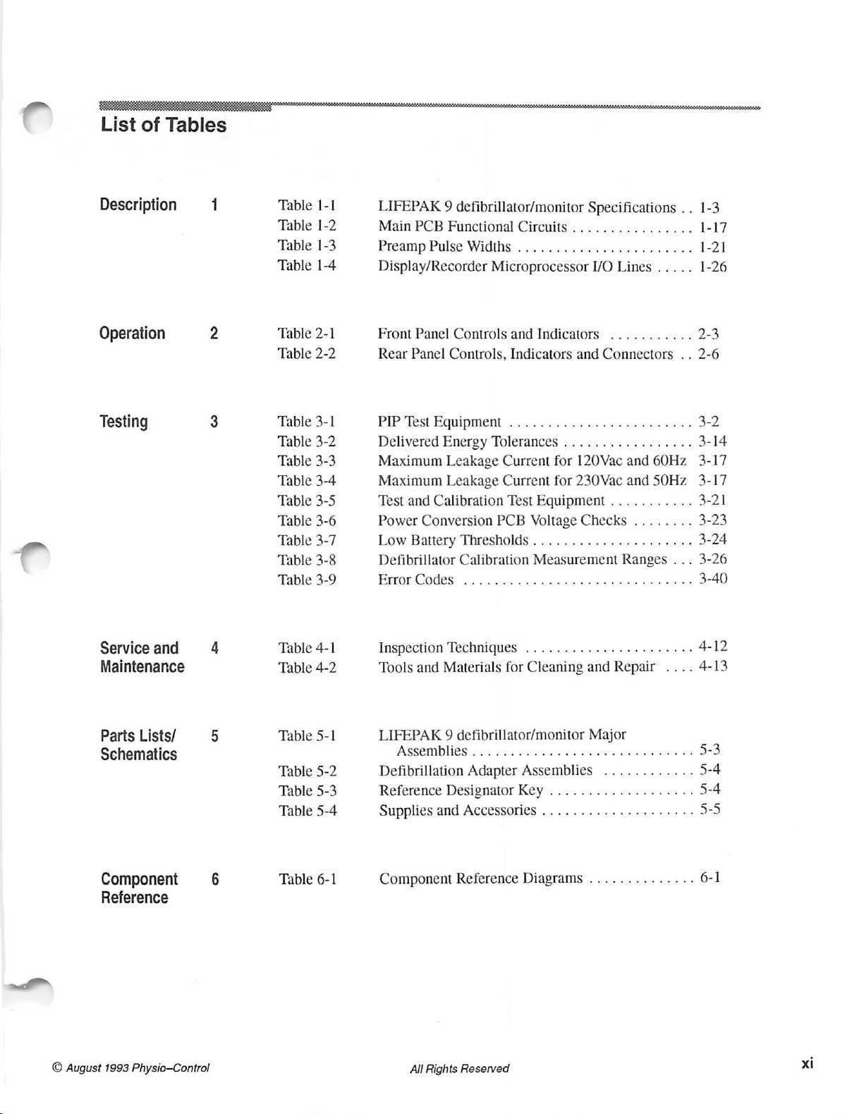
List
of
Tables
Description
Operation
Testing
1
2
3
Table
Table
Table
Table
Table
Table
Table
Table
Table
Table
Table
Table
Table
Table
Table
1-1
1-2
1-3
1-4
2-1
2-2
3-1
3-2
3-3
3-4
3-5
3-6
3-7
3-8
3-9
LIFEPAK 9 defibrillator/monitor
Main
PCB
FunctionalCircuits................
Preamp
Display/Recorder
Front
Rear
PIP
Delivered
Maximum
Maximum
Test
Power
Low
Defibrillator
οι
Pulse
Panel
Controls
Panel
Controls,
Test
Equipment
Energy
Leakage
Leakage
and
Calibration
Conversion
Battery
κια
Widths . .
Microprocessor
and
Indicators
...;:
Tolerances:
Current
Current
Test
PCB
Voltage
Thresholds
Calibration
ее
Indicators
and
css
for
120Vac
for
230Vac
Equipment
Checks
.....................
Measurement
ο
ο.
Specifications
sms
1/0
Lines
...........
Connectors
sia
à
à à à
and
and
...........
........
Ranges
..
sue.
.....
..
ss
60Hz
50Hz
...
1-3
1-17
1-21
1-26
2-3
2-6
3-2
3-14
3-17
3-17
3-21
3-23
3-24
3-26
3-40
Service
and
Maintenance
Parts
Lists/
Schematics
Component
Reference
4
5
6
Table
Table
Table
Table
Table
Table
Table
4-1
4-2
5-1
5-2
5-3
5-4
6-1
Inspection
Tools
LIFEPAK 9 defibrillator/monitor
Defibrillation
Reference
Supplies
Component
and
πο
Ημ
and
Techniques
Materials
Designator
Accessories
Reference
for
Adapter
......................
Cleaning
Assemblies
Key
....................
Diagrams
and
Major
...................
..............
Repair
............
....
4-12
4-13
3
5-4
5-4
5-5
6-1
©
August
1993
Physio—Control
All
Rights
Reserved
xi
Page 10
LIFEPAK 9 defibrillator/monitor
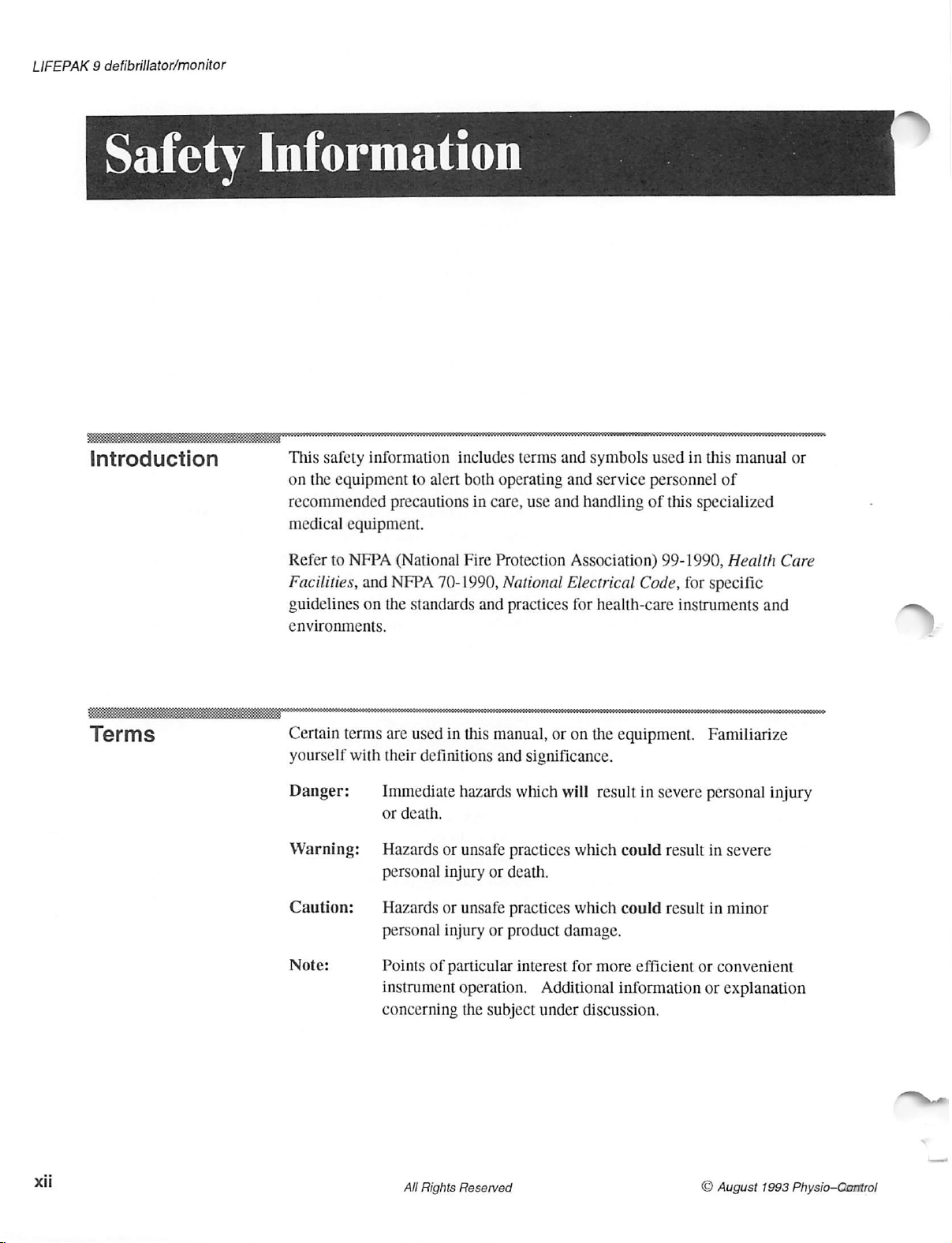
Safety
Introduction
Information
This
safety
information
on
the
equipment
recommended
medical
Refer
Facilities,
guidelines
environments.
equipment.
to
NFPA
and
on
the
precautions
(National
NFPA
includes
to
alert
both
operating
in
care,
Fire
Protection
70-1990, National
standards
and
terms
and
and
use
and
Association)
Electrical
practices
for
symbols
service
handling
health-care
of
Code,
used
in
this
personnel
this
specialized
99-1990,
for
instruments
manual
of
Health
specific
or
Care
and
Terms
Certain
yourself
Danger:
Warning:
Caution: — Hazards
Note:
terms
with
are
used
their
Immediate
or
death.
Hazards
personal
personal
Points
instrument
concerning
in
this
manual,
definitions
or
injury
or
injury
of
particular
and
hazards
unsafe
or
unsafe
or
operation.
the
subject
or
on
significance.
which
will
practices
death.
practices
product
interest
which
which
damage.
for
Additional
under
discussion.
the
equipment.
result
in
could
could
more
efficient
information
severe
result
result
or
Familiarize
personal
in
in
convenient
or
injury
severe
minor
explanation
xii
All
Rights
Reserved
O August
1993
Physio-Control
Page 11

Warnings
Following
in
result
cautions
are
descriptions
severe
death,
not
appearing
of
injury
in
this
general
product
or
section
hazards
damage.
are
found
and
unsafe
Specific
throughout
practices
warnings
the
manual.
that
and
could
Shock
Possible
Paddle
Possible
Hazard
Arcing
Damage
Fire
Explosion
Safety
Hazard
or
and
When
charged
discharges
Unless
may
procedure
LIFEPAK 9 defibrillator/monitor
When
standard
(STERNUM
arcing
paddle
Do
presence
Refer
Facilities,
this
Do
location
other
discharged
Cause
discharging
and
electrode
not
operate
to
product
not
mount
mounting
and
up
to
personal
unless
paddles
paddle
formation
this
of
flammable
NFPA
(National
and
NFPA
in
the
the
where
it
discharged,
360J
of
electrical
properly
injury
you
the
are
on
surfaces
product
proximity
product
cannot
location.
as
or
are
thoroughly
defibrillator
securely
the
left,
of
pits
on
can
in
gases
Fire
70-1990, National
directly
harm
the
LIFEPAK 9 defibrillator/monitor
energy
described
death.
and
into
and
properly
APEX
paddle
cause
oxygen-enriched
or
anesthetics.
Protection
of
flammable
above
the
patient
through
in
this
Do
not
attempt
familiar
all
accessories.
the
internal
stored
paddle
electrode
patient
skin
Association)
Electrical
gases
the
if
it
the
manual,
to
with
the
test
in
the
on
the
right).
surfaces.
burns
environments
Explosion
Code,
or
anesthetics.
patient.
should
fall
defibrillator
this
perform
operation
load,
paddle
This
Pitted
during
or
fire
99-1990,
before
Place
from
paddles.
electrical
this
of
the
make
sure
storage
helps
or
damaged
defibrillation.
or
in
the
can
result.
Health
operating
the
product
its
shelf
energy
the
area
prevent
Care
in
a
or
O August
Electrical
Possible
Hazard
Equipment
Failure
Shock
Possible
or
Fire
Equipment
Damage
1993
Physio-Control
and
Hazard
Do
not
operate
frayed
and
inspections
which
eventually
Do
spilling
damage.
instructions
possible
not
Do
not
wires,
equipment
on
the
wires
causes
immerse
any
fluids
sterilize
Do
clearly
equipment
or
loose
cables
enter
the
any
portion
on
this
product.
not
autoclave
approve
All
using
snap
fittings
failure.
and
wires.
the
terminals.
wire
strands
of
the
instrument
or
it.
Rights
damaged
may
Perform
Pay
to
the
instrument
Sterilization
gas
sterilize
Reserved
cables
cause
frequent
particular
Repeated
break.
or
accessories.
environments
and
wires.
interference
electrical
attention
flexing
in
accessories
at
water
unless
to
these
or
can
Broken
or
loss
of
and
visual
the
point
points
other
fluids.
cause
manufacturer
or
signal
at
Avoid
serious
xiii
Page 12

LIFEPAK 9 defibrillator/monitor
Safety
Shock
Risk
or
Fire
Hazard
Do
not
Table
work
improperly.
Make
NFPA
Code.
substitute
5-4
shown
sure
that
(National
accessories.
on
page
5-5.
all
equipment
Fire
Protection
Use
only
recommended
Substitution
is
interconnected
Association)
may
cause
safely
70-1990,
accessories
the
instrument
in
accordance
National
Electrical
listed
to
with
in
Symbols
Note:
Any
or
all
equipment:
>
ATTENTION
+
>
al
>||S
TET
als
Within
accessory
laboratory.
applications
grounding
accessory
certain
equipment
It
in
requirements
equipment.
of
the
following
Static
Sensitive
Additional
DANGER
ATTENTION
Defibrillation
Defibrillation
governmental
must
be
is
important
your
symbols may
Device
information
—
high
—
refer
protected,
protected,
that
location.
after
(SSD)
in
voltage
to
jurisdictions,
labeled
interconnecting
Section
manual
type
type
by an
you
verify
Check
leakage
appear
6,
present
for
CF
patient
BF
patient
and
in
this
Component
more
all
interconnected
approved
observe
current
this
manual
connection
connection
testing
and
instrument
or
References
information
the
required
on
with
the
xiv
Protective
©
Fusible
Equipotentiality
Off
On
ECG
®=04
Link
(Power:
(Power:
Output
All
Rights
ground
(earth)
connector
disconnection
connection
Reserved
terminal
from
to
the
AC
the
mains)
mains)
O
August
1993
Physio-Control
Page 13
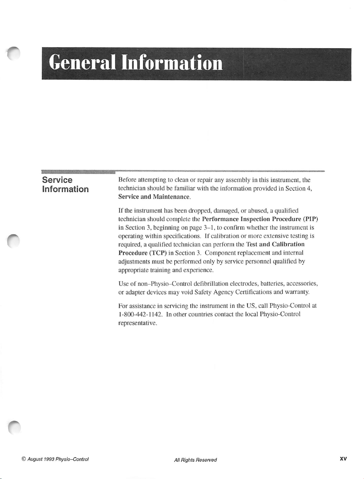
General
Information
Service
Information
Before
technician
Service
If
technician
in
operating
required, a qualified
Procedure
adjustments
appropriate
attempting
and
the
instrument
Section
to
clean
should
be
familiar
Maintenance.
has
been
should
3,
within
complete
beginning
specifications.
technician
(TCP)
in
must
be
training
Section
performed
and
or
repair
with
dropped,
the
Performance
on
page
3-1,
If
can
3.
Component
only
experience.
any
assembly
the
information
damaged,
to
calibration
perform
by
or
Inspection
confirm
or
the
replacement
service
in
this
instrument,
provided
abused, a qualified
whether
more
Test
and
personnel
in
Section
Procedure
the
instrument
extensive
Calibration
and
internal
qualified
testing
the
4,
(PIP)
is
is
by
©
August
1993
Physio—Control
Use
of
non—Physio—Control
or
adapter devices
For
assistance
1-800-442-1142.
representative.
in
may
void
servicing
In
other
countries
All
Rights
defibrillation
Safety
the
Agency
instrument
contact
Reserved
electrodes,
Certifications
in
the
the
batteries,
US,
call
local
Physio-Control
accessories,
and
warranty.
Physio-Control
at
xv
Page 14
LIFEPAK 9 defibrillator/monitor
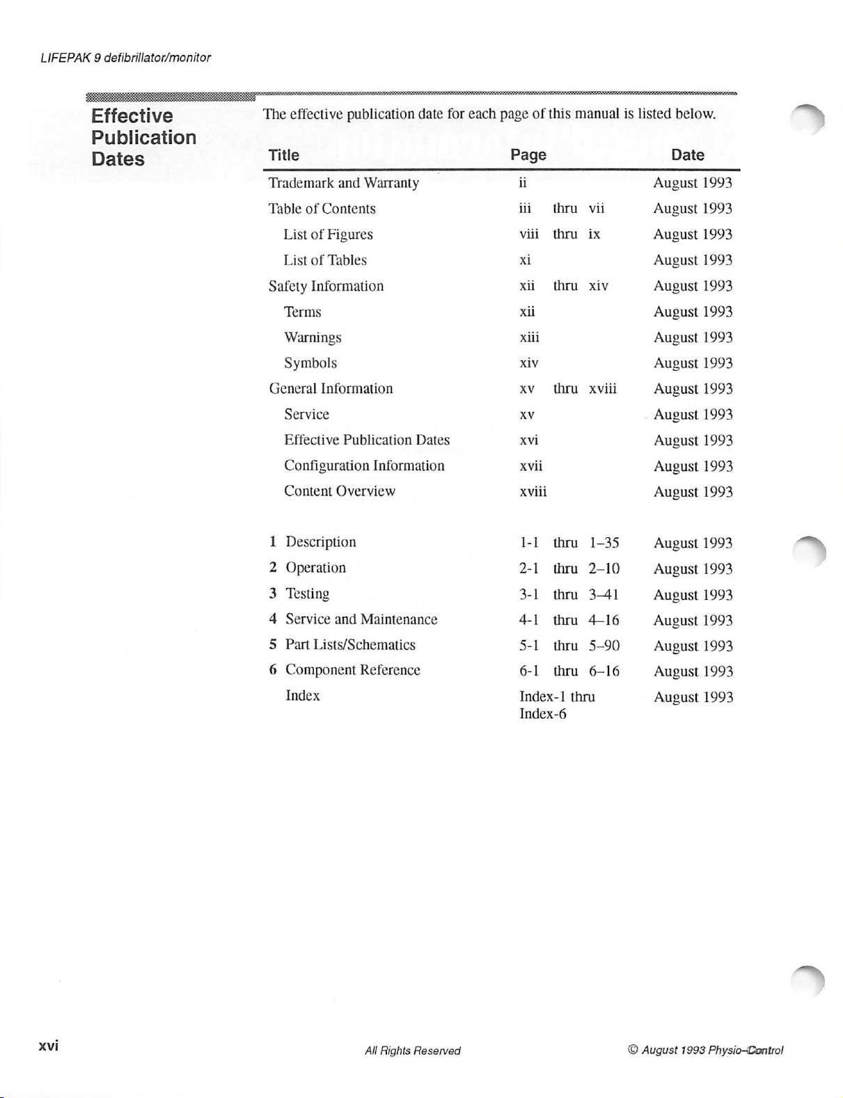
Effective
Publication
Dates
The
effective
Title
Trademark
Table
List
List
and
of
Contents
of
Figures
of
Tables
publication
date
Warranty
for
each
page
Page
ii
ii
viii
xi
of
this
thru
thru
manual
vii
ix
is
listed
below.
Date
August
August
August
August
1993
1993
1993
1993
Safety
Information
Terms
Warnings
Symbols
General
Information
Service
Effective
Configuration
Content
1
Description
2
Operation
3
Testing
4
Service
5
Part
6
Component
Overview
and
Lists/Schematics
Publication
Information
Maintenance
Reference
Dates
xi
xii
xiii
xiv
χν
XV
Xvi
xvii
xviii
1-
2-1
3-1
4-1
5-1
6-1
thru
thru
thru
thru
thru
thru
thru
thru
xiv
xviii
1-35
2-10
3-41
4-16
5-90
6-16
August
August
August
August
August
August
August
August
August
August
August
August
August
August
August
1993
1993
1993
1993
1993
1993
1993
1993
1993
1993
1993
1993
1993
1993
1993
xvi
Index
All
Rights
Reserved
Index-1
Index-6
thru
©
August
August
1993
1993
Physio-Control
Page 15
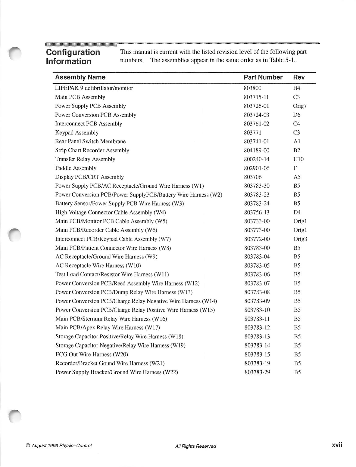
Configuration
Information
Assembly
Name
This
numbers.
LIFEPAK 9 defibrillator/monitor
Main
PCB
Assembly
Power
Supply
Power
Conversion
Interconnect
Keypad
Rear
Panel
Strip
Chart
Transfer
Paddle
Display
Power
Supply
Power
Conversion
Battery
High
Voltage
Main
PCB/Monitor
Main
PCB/Recorder
Interconnect
Main
PCB/Patient
AC
Receptacle/Ground
AC
Receptacle
Test
Load
Power
Conversion
Power
Conversion
Power
Conversion
Power
Conversion
Main
PCB/Sternum
Main
PCB/Apex
Storage
Storage
ECG
Out
Recorder/Bracket
Power
Supply
PCB
Assembly
PCB
PCB
Assembly
Assembly
Switch
Relay
Assembly
PCB/CRT
Membrane
Recorder
Assembly
Assembly
PCB/AC
PCB/Power
Assembly
Sensor/Power
Connector
PCB
Cable
PCB/Keypad
Connector
Wire
Harness
Contact/Resistor
PCB/Reed
PCB/Dump
PCB/Charge
PCB/Charge
Relay
Relay
Capacitor
Capacitor
Wire
Positive/Relay
Negative/Relay
Harness
Gound
Bracket/Ground
Assembly
Receptacle/Ground
Supply
PCB
Cable
Cable
Assembly
Cable
Wire
Wire
Harness
(W
Wire
Assembly
Wire
Wire
Harness
(W20)
Wire
manual
SupplyPCB/Battery
Assembly
Assembly
Assembly
is
The
Wire
Harness
(W4)
(W5)
(W6)
Harness
current
assemblies
Wire
(W7)
(W8)
(W9)
10)
Harness
Relay
Relay
Relay
Harness
Wire
Harness
Wire
(W11)
Wire
Harness
Wire
Harness
Negative
Positive
Wire
Wire
(W16) 803783-11
(W17)
Harness
Wire
Harness
Harness
(W21)
(W18)
(W19)
(W22)
with
Harness
Wire
(W3)
(W12)
(W13)
Harness
Harness
the
listed
appear
(W1)
Harness
(W14)
(W15)
revision
in
the
same
(W2)
level
of
the
order
as
in
PartNumber
803800
803715-11
803726-01
803724-03
803761-02
803771
803741-01
804189-00
800240-14
802901-06
803706
803783-30
803783-23
803783-24
803756-13
803733-00
803773-00
803772-00
803783-00
803783-04
803783-05
803783-06
803783-07
803783-08
803783-09
803783-10
803783-12
803783-13
803783-14
803783-15
803783-19
803783-29
following
Table
part
5-1.
Rev
H4
C3
Orig7
D6
C4
C3
Al
B2
U10
F
AS
BS
BS
BS
D4
Orig]
Orig]
Orig3
BS
BS
BS
BS
BS
BS
BS
BS
BS
BS
BS
BS
BS
BS
BS
August
©
Physio-Control
1993
Rights
All
Reserved
xvii
Page 16
LIFEPAK 9 defibrillator/monitor
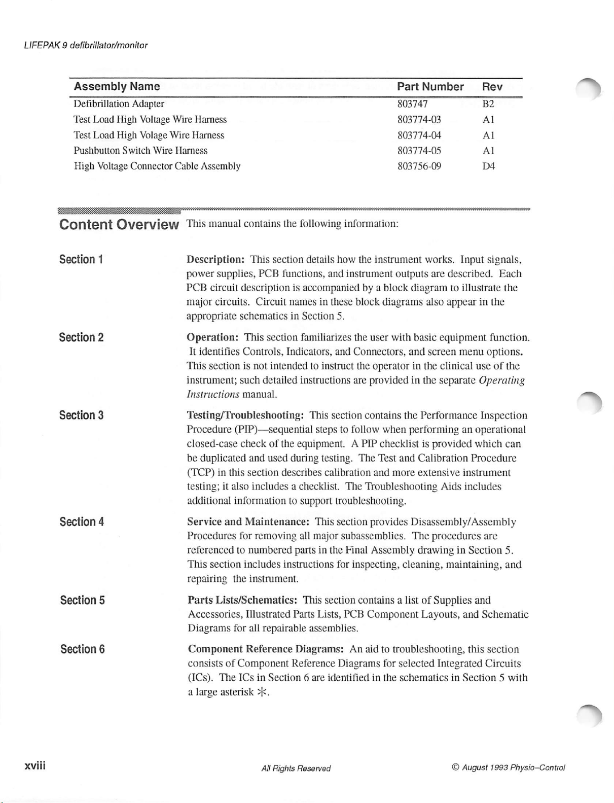
Assembly Name
Defibrillation
Test
Load
Test
Load
Pushbutton
High
Voltage
Content
Adapter
High
Voltage
High
Volage
Switch
Wire
Connector
Overview
Wire
Harness
Wire
Harness
Harness
Cable
This
Assembly
manual
contains
the
following
PartNumber
803747
803774-03
803774-04
803774-05
803756-09
information:
Rev
B2
Al
Al
Al
D4
Section
Section
Section
Section
1
2
3
4
Description:
power
supplies,
PCB
circuit
major
circuits.
appropriate
Operation:
It
identifies
This
section
instrument;
Instructions
This
section
PCB
functions,
description
Circuit
schematics
This
Controls,
is
not
such
names
in
section
Indicators, and
intended
detailed
manual.
is
accompanied
Section
familiarizes
instructions
Testing/Troubleshooting:
Procedure
closed-case
be
duplicated
(TCP)
testing;
additional
Service
Procedures
referenced
This
repairing
(PIP)—sequential
check
and
in
this
section
it
also
includes a checklist.
information
and
Maintenance:
for
removing
to
numbered
section
includes
the
instrument.
of
the
equipment. A PIP checklist
used
during
describes
to
support
all
parts
instructions
details
and
in
these
how
instrument
5.
the
Connectors,
to
instruct
are
This
section
steps
to
follow
testing.
calibration
The
troubleshooting.
This
section
major
subassemblies.
in
the
Final
for
inspecting,
the
instrument
outputs
by a block
block
user
diagram
diagrams
with
basic
and
the
operator
provided
contains
The
Test
and
the
when
and
more
in
in
performing
Calibration
extensive
Troubleshooting
provides
Disassembly/Assembly
The
Assembly
drawing
cleaning,
works.
also
Input
are
described.
to
appear
illustrate
equipment
screen
the
the
menu
clinical
separate
Performance
an
is
provided
Procedure
instrument
Aids
includes
procedures
in
Section
maintaining,
signals,
Each
the
in
the
function.
options.
use
of
the
Operating
Inspection
operational
which
can
are
5.
and
xviii
Section
Section
5
6
Parts
Lists/Schematics:
Accessories,
Diagrams
Illustrated
for
Component
consists
(ICs).
a
The
large
asterisk
of
Component
ICs
all
repairable
Reference
in
Section 6 are
>.
All
Rights
This
section
Parts
Lists,
assemblies.
Diagrams:
Reference
identified
Reserved
contains a list
PCB
Component
An
aid
to
Diagrams
in
for
the
of
Supplies
Layouts,
troubleshooting,
selected
schematics
and
this
Integrated
in
Section 5 with
©
August
and
Schematic
section
Circuits
1993
Physio-Control
Page 17
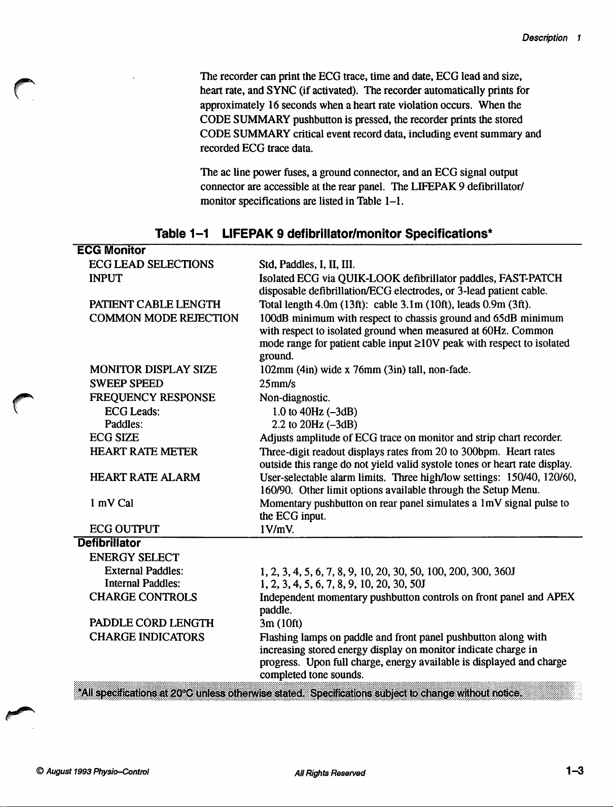
The
recorder
heart
rate,
approximately
CODE
CODE
recorded
The
ac
connector
monitor
can
and
SUMMARY
SUMMARY
ECG
line
power
are
specifications
print
the
SYNC
16
seconds
(if
pushbutton
critical
trace
data.
fuses, a ground
accessible
at
are
ECG
trace,
time
activated).
when a heart
event
the
listed
The
is
pressed,
record
connector,
rear
panel.
in
Table
and
date,
recorder
rate
violation
the
recorder
data,
including
and
The
LIFEPAK 9 defibrillator/
1-1.
ECG
lead
and
automatically
occurs.
prints
event
an
ECG
prints
When
the
summary
signal
size,
for
the
stored
output
Description
and
1
ECG
Monitor
ECG
LEAD
INPUT
PATIENT
COMMON
MONITOR
SWEEP
FREOUENCY
ECG
HEART
HEART
1
ECG
mV
SPEED
ECG
Leads:
Paddles:
SIZE
RATE
RATE
Cal
OUTPUT
Defibrillator
ENERGY
External
Internal
CHARGE
PADDLE
CHARGE
Table
SELECTIONS
CABLE
MODE
DISPLAY
SELECT
Paddles:
CONTROLS
CORD
INDICATORS
LENGTH
REJECTION
RESPONSE
METER
ALARM
Paddles:
LENGTH
1-1
SIZE
LIFEPAK 9 defibrillator/monitor
Std,
Paddles,
Isolated
disposable
Total
length
100dB
with
respect
mode
range
ground.
102mm
I,
II,
ITI.
ECG
via
QUIK-LOOK
defibrillation/ECG
4.0m
(13ft):
minimum
(4in)
with
to
isolated
for
patient
wide x 76mm
respect
cable input
cable
ground
Specifications*
defibrillator
electrodes,
3.1m
to
chassis
when
(3in)
tall,
25mm/s
Non-diagnostic.
1.0
to
40Hz
(-3dB)
2.2
to
20Hz
(-3dB)
Adjusts
Three-digit
outside
User-selectable
160/90.
Momentary
the
amplitude
this
Other
ECG
input.
of
ECG
readout
range
displays
do
not
alarm
limit
options
pushbutton
trace
rates
yield
limits.
Three
available
on
rear
on
from
valid
panel
1V/mV.
1,
2,
3,
4,
S, 6,
7,
8,
9,
10,
20,
30,
50,
1,
2,
3,
4,
5,
6,
7,
8,
9,
10,
20,
30,
SOJ
Independent
momentary
pushbutton
paddle.
3m
(10ft)
Flashing
increasing
progress.
completed
lamps
stored
Upon
tone
on
paddle
energy
full
charge,
sounds
and
front
display
energy
on
paddles,
or
3-lead
(10ft),
leads
ground
measured
210V
peak
with
non-fade.
monitor
systole
high/low
controls
panel
monitor
available
and
20
to
300bpm.
tones
settings:
through
simulates a 1mV
100,
the
200,
on
pushbutton
indicate
is
FAST-PATCH
patient
0.9m
(3ft).
and
65dB
at
60Hz.
Common
respect
strip
chart
Heart
or
heart
150/40,
Setup
Menu.
signal
300,
360J
front
panel
along
charge
displayed
cable.
minimum
to
isolated
recorder.
rates
rate
display.
120/60,
pulse
and
APEX
with
in
and
charge
to
©
August
1993
Physio—Control
All
Rights
Reserved
1-3
Page 18
LIFEPAK 9 defibrillator/monitor
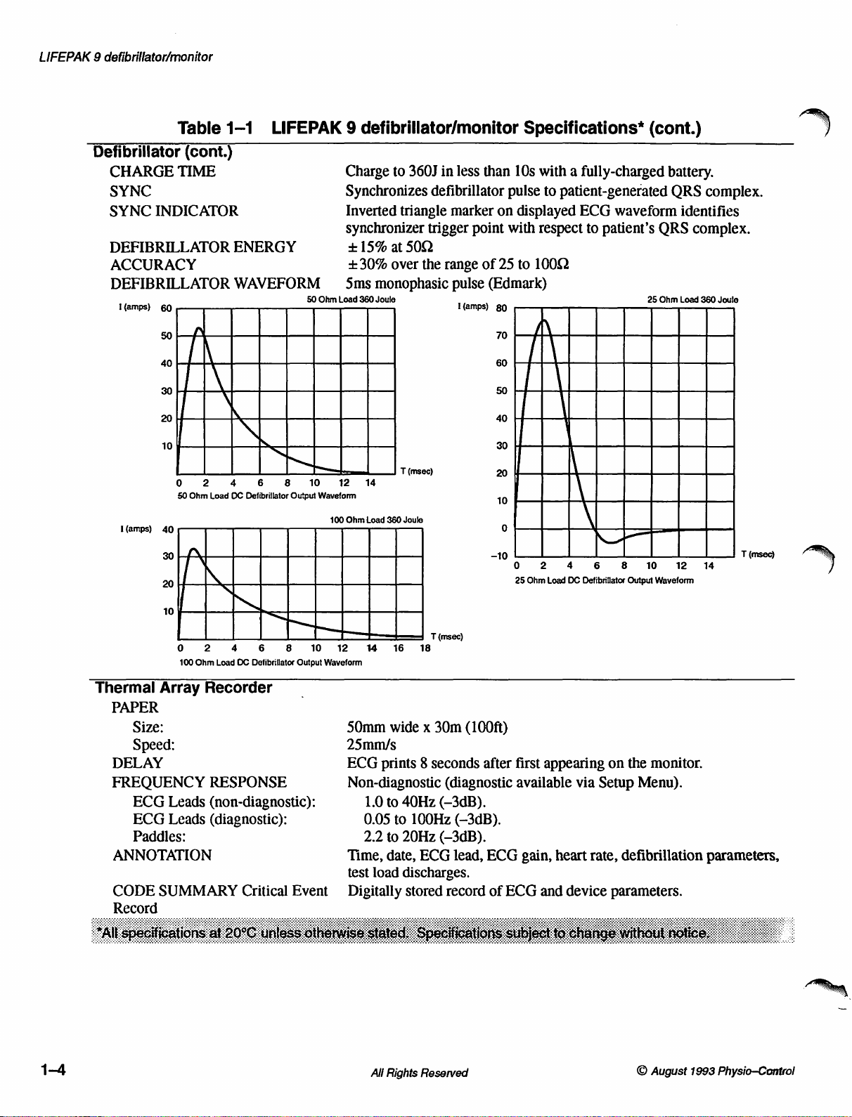
Table
Defibrillator
CHARGE
SYNC
SYNC
DEFIBRILLATOR
ACCURACY
DEFIBRILLATOR
1(amps)
I
(amps)
(cont.)
TIME
INDICATOR
60
50
40
|
30
20
10
0 2 4 6 8
50
Ohm
1-1
ENERGY
WAVEFORM
\
\
<
Load
OC
LIFEPAK 9 defibrillator/monitor
NM
NT
Defibrillator
Output
Charge
Synchronizes
Inverted
synchronizer
+
+30%
—
Sms
50
Ohm
Load
10
12 14
Waveform
100
Ohm
to
360J
triangle
15%
at
500
over
monophasic
360
Joule
T
(msec)
Load
360
Joule
in
less
than
defibrillator
marker
trigger
the
point
range
pulse
L(amps)
of
Specifications*
10s
with a fully-charged
pulse
to
patient-generated
on
displayed
with
respect
25
to
1000
(Edmark)
80
70
60
50
40
30
20
10
0
ECG
waveform
to
patient’s
(cont.)
battery.
QRS
identifies
QRS
complex.
25
Ohm
Load
360
complex.
Joule
Thermal
PAPER
Size:
Speed:
DELAY
FREQUENCY
ECG
ECG
Paddles:
ANNOTATION
CODE
Record
0 2
100
Ohm
Array
SUMMARY
Recorder
RESPONSE
Leads
(non-diagnostic):
Leads
(diagnostic):
4
Load
OC
Critical
6 8
Defibrillator
Output
Event
10 12
14
Waveform
50mm
25mm/s
ECG
Non-diagnostic
1.0
0.05
2.2
Time,
test
Digitally
T
16
wide x 30m
prints 8 seconds
to
to
to
date,
load
(msec)
18
(diagnostic
40Hz
(-3dB).
100Hz
20Hz
discharges.
stored
(-3dB).
ECG
(-3dB).
lead,
record
-10
(100ft)
after
ECG
of
ECG
0
2
4
6
8
25
Ohm
Load
DC
Defibrillator
first
appearing
available
gain,
heart
and
device
on
via
Setup
rate,
parameters.
defibrillation
10
Output
Waveform
the
monitor.
Menu).
12
14
parameters,
T
(msec)
1-4
Rights
All
Reserved
August
©
Physio-Control
1993
Page 19
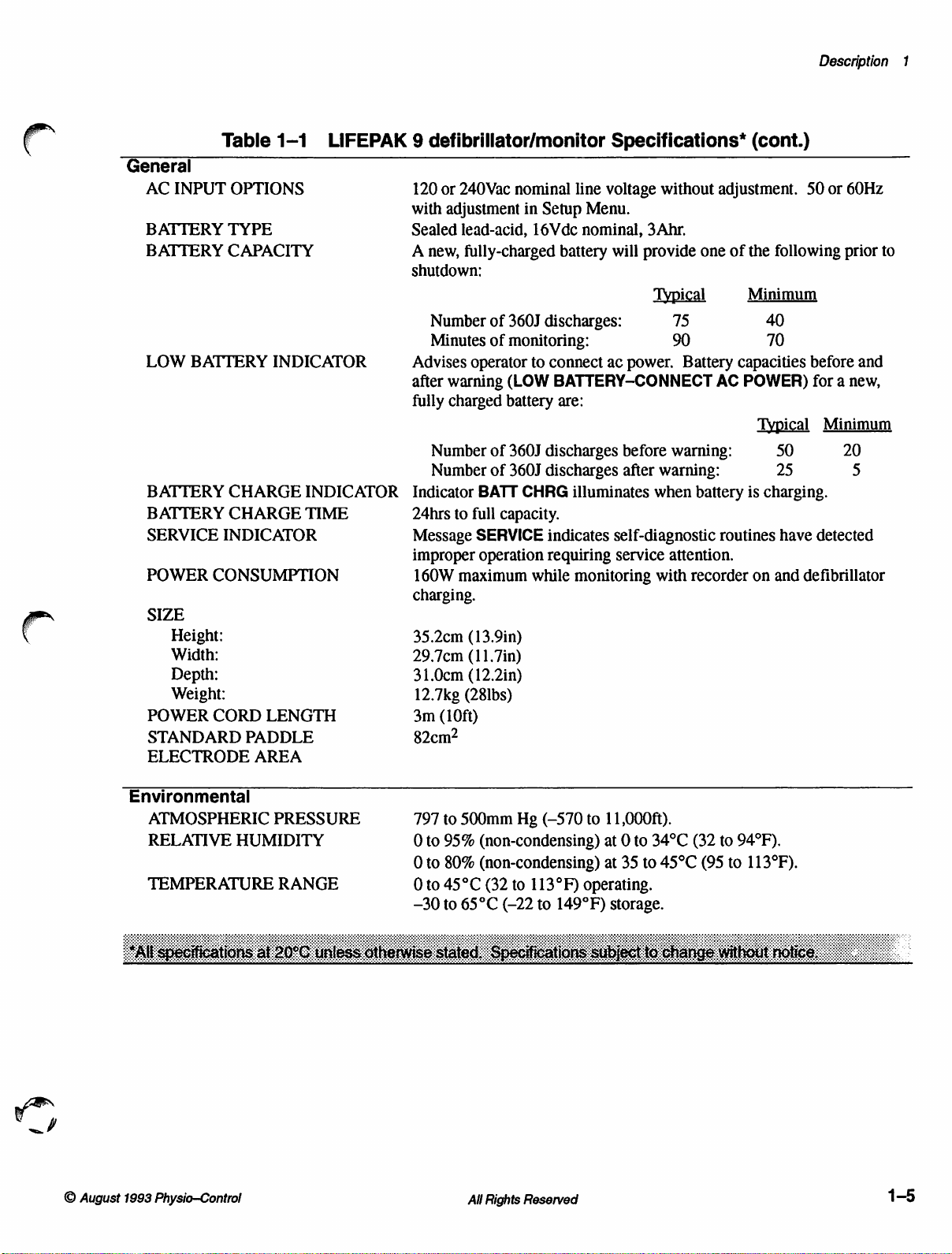
Description
1
General
AC
BATTERY
BATTERY
LOW
BATTERY
BATTERY
SERVICE
POWER
SIZE
POWER
STANDARD
ELECTRODE
Table
INPUT
BATTERY
CONSUMPTION
Height:
Width:
Depth:
Weight:
CORD
1-1
OPTIONS
TYPE
CAPACITY
INDICATOR
CHARGE
CHARGE
INDICATOR
LENGTH
PADDLE
AREA
LIFEPAK 9 defibrillator/monitor
120
or
with
adjustment
Sealed
A
new,
240Vac
lead-acid,
fully-charged
nominal
in
Setup
16Vdc
battery
shutdown:
INDICATOR
TIME
Number
Minutes
Advises
after
fully
Number
Number
Indicator
24hrs
Message
improper
160W
of
of
operator
warning
charged
of
of
BATT
to
full
SERVICE
operation
maximum
360J
discharges:
monitoring:
to
connect
(LOW
BATTERY-CONNECT
battery
360J
360J
capacity.
are:
discharges
discharges
CHRG
indicates
requiring
while
illuminates
monitoring
charging.
35.2cm
29.7cm
31.0cm
12.7kg
3m
(13.9in)
(11.7in)
(12.2in)
(28lbs)
(10ft)
82cm?
Specifications*
line
voltage
Menu.
nominal, 3 Ahr.
will
ac
without
provide
Typical
75
90
power.
before
after
self-diagnostic
service
warning:
warning:
when
attention.
with
adjustment.
one
of
Battery
AC
battery
routines
recorder
(cont.)
50
the
following
Minimum
40
70
capacities
POWER)
Typical
is
on
before
50
25
charging.
have
and
defibrillator
or
60Hz
prior
and
for a new,
Minimum
20
5
detected
to
©
August
Environmental
ATMOSPHERIC
RELATIVE
TEMPERATURE
1993
Physio—Control
PRESSURE
HUMIDITY
RANGE
797
0 to
0 to
0
to
—30
to
500mm
95%
80%
45°C
to
65°C
All
Hg
(non-condensing)
(non-condensing)
(32
to
(-22
Rights
Reserved
(-570
113°F)
to
149°F)
to
11,000ft).
at 0 to
at
35
34°C
to
operating.
storage.
45°C
(32
(95
to
94°F).
to
113°F).
1-5
Page 20
LIFEPAK 9 defibrillator/monitor
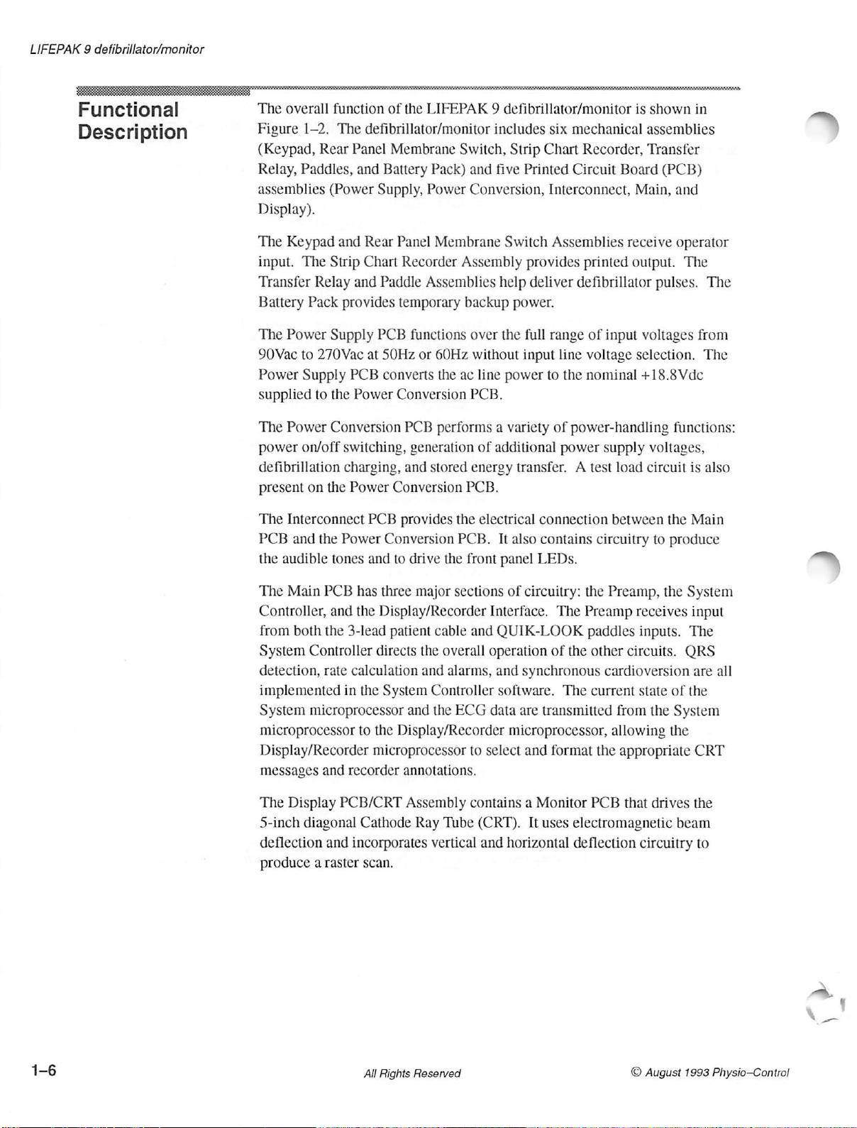
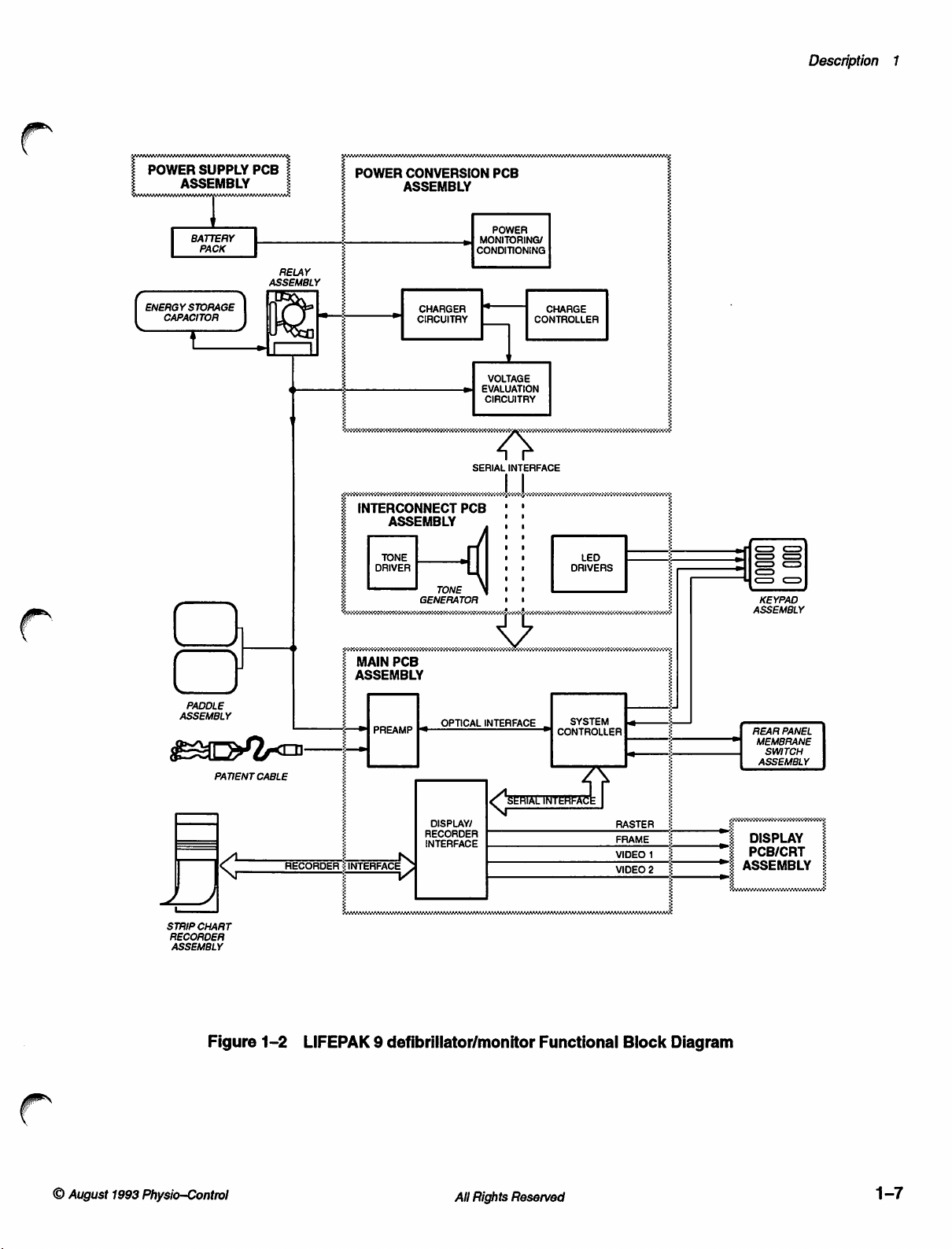
Functional
Descri
ption
The
overall
Figure
(Keypad,
Relay,
assemblies
function
1-2.
Rear
Paddles,
(Power
Display).
The
Keypad
input.
Transfer
Battery
The
90Vac
Power
supplied
The
power
The
Relay
Pack
Power
to
270Vac
Supply
to
Power
on/off
Strip
Supply
the
Conversion
defibrillation
present
on
the
of
the
LIFEPAK 9 defibrillator/monitor
The
defibrillator/monitor
Panel
Membrane
and Battery
Supply,
and
Rear
Chart
and
Paddle
provides
PCB
at
50Hz
PCB
converts
Power
switching,
charging,
Power
Pack)
Power
Panel
Membrane
Recorder
Assemblies
temporary
functions
or
60Hz
the
Conversion
PCB
performs a variety
generation
and
stored
Conversion
includes
Switch,
and
Strip
five
Conversion,
Switch
Assembly
help
backup
over
ac
power.
the
without
line
power
input
PCB.
of
additional
energy
transfer. A test
PCB.
six
mechanical
Chart
Recorder,
Printed
Circuit
Interconnect,
Assemblies
provides
deliver
full
printed
defibrillator
range
line
voltage
to
the
nominal
of
power-handling
power
of
input
supply
is
shown
assemblies
Transfer
Board
(PCB)
Main,
receive
output.
pulses.
voltages
selection.
+18.8Vdc
voltages,
load
circuit
in
and
operator
The
The
from
The
functions:
is
also
The
Interconnect
PCB
and
the
Power
the
audible
The
Main
Controller,
from
System
detection,
implemented
System
microprocessor
tones
PCB
has
and
the
both
the
3-lead
Controller
rate
calculation
in
the
microprocessor
to
Display/Recorder
messages
The Display
5-inch
deflection
produce a raster
and
recorder
PCB/CRT
diagonal
and
Cathode
incorporates
scan.
PCB
provides
Conversion
and
to
drive
three
the
major
the
PCB.
sections
Display/Recorder
patient
directs
System
the
cable
the
overall
and
alarms,
Controller
and
the
ECG
Display/Recorder
microprocessor
annotations.
Assembly
Ray
Tube
vertical
electrical
front
Interface.
and
operation
data
connection
It
also
contains
panel
LEDs.
of
circuitry:
QUIK-LOOK
of
and
synchronous
software.
are
transmitted
The
the
The
microprocessor,
to
select
and
format
contains a Monitor
(CRT).
and
It
uses
electromagnetic
horizontal
deflection
between
circuitry
the
Preamp,
Preamp
paddles
other
to
receives
inputs.
circuits.
cardioversion
current
state
from
the
allowing
the
appropriate
PCB
that
drives
circuitry
the
Main
produce
the
System
input
The
QRS
are
of
the
System
the
CRT
the
beam
to
all
1-6
All
Rights
Reserved
© August
1993
Physio—Control
Page 21
Description
1
の
POWER
ENEAGY
SUPPLY
ASSEMBLY
BATTERY
PACK
STORAGE CHARGER
CAPACITOR
PCB
|
|
RELAY
ASSEMBLY
1
¿
POWER
|
“|
INTERCONNECT
ASSEMBLY
TONE
DRIVER
CONVERSION
ASSEMBLY
CONDITIONING
CIRCUITAY
4]
SERIAL
PCB
TONE
GENERATOR | |!
PCB
POWER
MONITORING/
È
VOLTAGE
EVALUATION
CIRCUITRY
INTERFACE
| +
!
o
,,
vt
Vos
bhi
CHARGE
CONTROLLER
DRIVERS
LED
人
iss
=
<>
O
=>
KEYPAD
ASSEMBLY
PADDLE
ASSEMBLY
PATIENT
STRIP
CHART
RECORDER
ASSEMBLY
Figure
く
>
CABLE
RECORDER:INTERFACE
1-2
LIFEPAK 9 defibrillator/monitor
A
мик
PREAMP
5
PCB
Fs
DISPLAW
INTERFACE
INTERFACE
N
Y
MAIN
ASSEMBLY
#1
E
OPTICAL
ο
D.
INTERFACE
vece
es
SYSTEM
#1
CONTROLLER
]
Functional
[
RASTER
FRAME
VIDEO
VIDEO
+
1
2
Block
Diagram
_
i
=
„z
"E
ASSEMBLY
REAR
PANEL
MEMBRANE
SWITCH
ASSEMBLY
=
DISPLAY
PCB/CRT
©
August
1993
Physio—Control
All
Rights
Reserved
1-7
Page 22
LIFEPAK 9 defibrillator/monitor
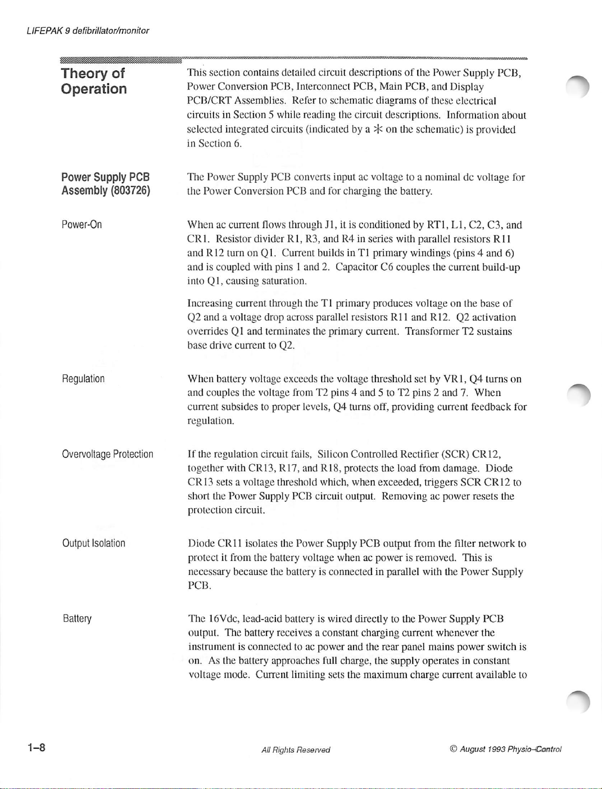
Theory
of
Operation
Power
Assembly
Power-On
Supply
(803726)
PCB
This
section
Power
Conversion
PCB/CRT
circuits
selected
in
Section
The
Power
the
Power
When
ac
CRI.
Resistor
and
R12
and
is
coupled
into
QI,
Increasing
Q2
and a voltage
overrides
base
drive
contains
PCB,
Assemblies.
in
Section 5 while
integrated
circuits
6.
Supply
PCB
Conversion
current
turn
causing
flows
divider
on
Q1.
with
saturation.
current
pins 1 and
through
drop
QI
and
terminates
current
to
detailed
circuit
Interconnect
Refer
to
reading
(indicated
converts
PCB
and
through
R1,
R3,
Current
builds
the
across
parallel
the
Q2.
descriptions
PCB,
schematic
the
by a >k
input
for
charging
J1,
it
is
and
R4
in
2.
Capacitor
TI
primary
resistors
primary
Main
diagrams
circuit
descriptions.
on
ac
voltage
the
the
battery.
conditioned
in
series
with
T1
primary
C6
couples
produces
R11
current.
of
the
Power
PCB,
and
Display
of
these
electrical
Information
schematic)
to a nominal
by
RT1,
L1,
parallel
windings
voltage
and
the
R12.
current
on
resistors
(pins 4 and
Q2
Transformer
Supply
PCB,
about
is
provided
dc
voltage
C2,
for
C3, and
R11
6)
build-up
the
base
of
activation
T2 sustains
Regulation
Overvoltage
Output
Protection
Isolation
Battery
When
battery
and
couples
current
subsides
regulation.
If
the
regulation
together
CR13
short
protection
Diode
protect
necessary
with
sets a voltage
the
Power
circuit.
CR11
it
from
because
PCB;
The
16Vdc,
output.
instrument
on.
voltage
As
The
is
the
battery
mode.
voltage
the
CR13,
exceeds
voltage
to
proper
circuit
R17,
threshold
Supply
isolates
the
battery
the
the
lead-acid
battery
receives a constant
connected
approaches
Current
from
T2
levels,
fails,
and
PCB
circuit
Power
voltage
battery
battery
to
ac
limiting
the
voltage
pins 4 and 5 to
Q4
turns
Silicon
R18,
which,
Controlled
protects
when
output.
Supply
is
connected
is
wired
when
directly
PCB
ac
charging
power
full
sets
and
charge,
the
maximum
threshold
T2
off,
providing
Rectifier
the
load
exceeded,
Removing
output
power
in
parallel
to
the
current
the
rear
panel
the
supply
set
by
pins 2 and
current
from
triggers
ac
from
the
is
removed.
with
Power
whenever
mains
operates
charge
VR1,
Q4
7.
feedback
(SCR)
CR12,
damage.
SCR
power
resets
filter
This
the
Power
Supply
power
in
current
turns
on
When
Diode
CR12
the
network
is
Supply
PCB
the
switch
constant
available
for
to
to
is
to
All
Rights
Reserved
© August
1993
Physio-Control
Page 23

BATT
CHRG
Power
PCB
Conversion
Assembly
(803724)
Power
Control
Indicator
the
battery
Power
charging a severely
A
battery-charging
indicator
panel
the
indicator
The
Power
additional
charging,
The
Power
control
Control
Control
Charger
at
approximately
Supply
mains
PCB
whenever
power
from
Conversion
voltage
and
defibrillation
Control
instrument
circuit
Input,
Low
circuits.
switch
lighting
generation
operation.
are:
sources
depleted
LED
the
signal
ac
power
is
if
current
PCB
energy
circuit
regulates
Switching
Energy
Charge
+4.5A.
battery.
on.
the
This
into a dead
illuminates
is
connected
An
interlock
battery
contains
and
monitoring,
transfer.
battery
The
circuits
Power
Rate,
limit
is
short, a requirement
the
front
to
in
is
not
installed.
circuitry
Supply,
for
energy
Refer
voltage
directly
Logic
and
Energy
implemented
panel
BATT
the
instrument
the
battery
power
on/off
storage
to
Figure
for
the
affected
Power
Storage
circuits
when
when
CHRG
and
the
harness
switching,
capacitor
1-3,
page
which
by
the
Power
Monitor,
Capacitor
Description
the
rear
prevents
1-10.
External
1
The
Front
Panel
the
Power
power
which
gate
PWR
SWBATT
circuits.
When
V
BATT
the
PWR
low-to-high
disabling
Control
connector:
of
Q11).
Control
on), V BATT
in
turn
of
Q11
SW
MONITOR
voltage
the
power
is
SW
the
circuit
ON
momentary
circuit.
passes
causes
by
divided
MONITOR
transition
Power
R60
Q10
R52,
which
for
switch
by
Control
may
be
(connects
pushbutton
When
the
to
the
gate
to
conduct. A portion
keeps
Q10
line
is
low
and
the
rest
of
the
is
pressed a second
R108
and
R109,
line
high.
and
activates
circuit.
confirmed
to
the
by
gate
provides
power
Power
The
the
The
monitoring
switch
of
Q11,
causing
of V BATT
conducting.
the
Power
Conversion
time
forward-biasing
System
Logic
Power
functional
of
Q10)
and
the
start-up
is
first
pressed
Q11
to
conduct,
is
held
During
Control
(turning
microprocessor
integrity
two
R57
this
circuit
PCB
power
CR44
Monitor
pins
on
(connects
Assembly
and
circuit,
of
the
signal
(turning
on
the
time
the
provides
off),
switching
reads
the
the
Power
test
to
the
gate
for
the
©
August
1993
Physio-Control
All
Rights
Reserved
1—9
Page 24
LIFEPAK 9 defibrillator/monitor
BATTERY
Goon
W
SW BATT2
TRANSFER
RELAY
DUMP
COIL
À
TRANSFER
COIL
PADDLES
1
(O
chance
)
Js
POWER
ENERGY
MONITOR
ENABLE
юж
CONTROL
1
SW
BATT MAIN
|
POWER q —
#1
MONITOR
+2.5V
|
ENERGY
DUMP
|
ENERGY
TRANSFER
+15V | δν
TIT
ANALOG
si
VOLTAGE
EVALUATION
Lili
SW
VBATT
BATT
a
+2.5V
SWITCHING
POWER
PWR
POWER
OUMP
TRANSFER
TRANSFER
SLEEP
[<
[+
|
SUPPLYÎ
SW
MONITOR
ENABLE
INHIBIT
REQUEST
ENABLE
INHIBIT
+
„15V
|
ВА:
SERIAL
INTERFACE
È
CHARGE
DRIVE
}
LED
ono
VA
ur
CAPACITOR
CHARGE
CONTROL
ENERGY
CHARGE
STORAGE
CAPACITOR
LED
DRIVE
一
age
PCB
ー
SYSTEM
MICROPROCESSOR
14
DATA
Q
2
ì
|
D15
014
<
1
/
LOW
ENERGY
CHARGE
RATE
=
'
STORAGE
capacitor
CHARGEA
:
É
CHARGE
2 _ CHARGE
À _ CONVERTER
:
i
LED
INHIBIT
CONVERTER
CONVERTER
CLOCK
VO
CHARGE
VALID
Fr
DRIVE
FUNCTION
DATA
DATA
EXTERNAL
CONTROL
OUT
IN
INPUT
SELECT
fee
1-10
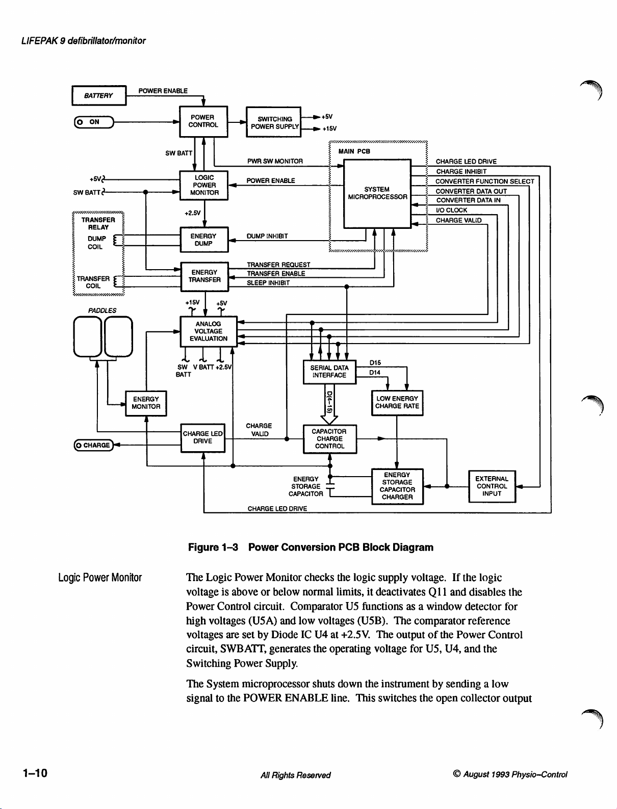
Logic
Power
Monitor
Figure
The
voltage
Power
high
voltages
circuit,
Switching
The
signal
1-3
Logic
is
Control
voltages
are
SWBATT,
System
to
the
Power
Power
above
(USA)
set
Power
microprocessor
POWER
Conversion
Monitor
or
below
circuit.
by
Comparator
and
Diode
generates
Supply.
ENABLE
All
Rights
PCB
checks
normal
low
IC
the
limits,
voltages
U4
at
+2.5V.
the
operating
shuts
down
line.
Reserved
Block
logic
it
US
functions
(USB).
the
This
Diagram
supply
deactivates
The
voltage
switches
voltage.
as a window
The
comparator
output
for
instrument
the
If
the
Q11
and
of
the
Power
U5,
U4,
by
sending a low
open
collector
©
August
logic
disables
detector
reference
Control
and
the
output
1993
the
for
Physio-Control
Page 25
of
USB
to
ground
Electrical
A
time
Control
during
detector
The
check
Voltage
and
isolation
delay
circuit
initial
(USA)
low-
and
circuit
measurements
R56
(relative
which
turns
is
provided
function
from
power-on.
high-limit
performance
and
to
in
the
shutting
Capacitor
C18
for
detector
check
the
+5V
off
by
Logic
down
the
low-limit
by
serving
the
supply).
Q11,
disabling
CR24
and
Power
while
operating
C26
accomplishes
inputs
to
as
test
accuracy
the
R39.
Monitor
detector
the
test
connector
points
of
voltage
Power
circuit
voltages
this
(USB).
to
measure
dividers
Control
prevents
are
still
for
the
high-limit
are
used
voltage.
R41,
Description
circuit.
the
Power
rising
to
R42,
R43,
1
Switching
External
Power
Control
Supply
Input
The
Switching
flyback-coupled
used
by
the
The
pulse-width
error
amplifier,
90Hz
by
the
outgoing
frequency
V
BATT
protect
primary.
The
N-channel
forward-biasing
System
energy
Q12
Energy
microprocessor
storage
voltage,
+5V
minimum.
Power
other
and
R30
and
pulse-width.
pulse
voltage
from
Storage
MOSFET,
capacitor
turning
Supply
inductor
circuits.
regulator
drive
C12.
The
by
driving
into
the
primary
high
voltages
Capacitor
Q9.
for
Q9
whenever
on
by
O9
off.
The
uses a pulse-width
(T2)
to
produce
U3
contains
circuitry
+15V
The
pulse
an
N-channel
caused
Charger
Two
resistors
the
Main
setting
inverting
an
for
Q12.
output
output
of
T2.
by
circuit
power
PCB
the
CHARGE
input
FET
Two
(R58
is
regulator
the
+5V
to
+15V
oscillator,
Oscillation
feedback
at
leakage
applied
initiates a charge
of
reference
frequency
at
U3
pin 2 determines
U3
pin 6 provides a constant
(Q12)
and
dumping
diodes,
is
and
CR28
inductance
externally
R59)
provide
to
the
INHIBIT
U2A
rises
instrument.
to
(U3)
and
a
supply
voltages
voltages,
is
the
and
CR29,
from
the
controlled
cycle
for
line
at
low
the
required
set
by
The
the
an
at
the
©
August
Energy
Storage
Charger
1993
Physio—Control
Capacitor
The
Energy
charge
the
05-07,
Amplitude
primary
controlled
Charge
+2.5V
to
the
circuit
απά
of
Control
reference
the
primary
consists
Storage
energy
(17.
comparators
Tl.
by
Capacitor
storage
of
The
input
the
External
circuits.
at
U2A
of
T1.
All
the
capacitor
following
U2A
and
to
the
Control,
If
any
pin
3,
Reserved
Rights
Charger
through
components:
U2B
energy
Low
of
these
the
output
circuit
determine
uses a flyback
the
Transfer
storage
Energy
incoming
capacitor
Charge
switches
T1,
U2A
the
drive
signals
high,
transformer
Relay.
at
Rate,
inhibiting
and
pulse
U2A
fall
The
U2B,
for
pin 2 is
and
Capacitor
below
the
core
01,
the
the
drive
to
of
02,
1-11
Page 26
LIFEPAK 9 defibrillator/monitor
Low
Energy
Charge
Rate
Once a charge
simultaneously
conducts,
provided
C17
is
zero.
C17.
When
low,
forcing
and
by
cycle
performs
Q7
Q7,
U2B,
When
the
voltage
U2A
T1.
The
power
circuit
function
handling
The
storage
potentials
limits
circuit-response
This
battery
a
low
the
power
charge
Capacitor
circuit
as
push-pull
for the
secondary
Capacitor
of
the
single
circuit
charge
is
voltage
battery
rate
required
energy
will
to
detect
drive
winding
up
to
pulse
time
centered
levels,
voltage
for
for
setting
not
the
initiates
shuts
Q7
output
to
the
at
two.separate
off.
Timing
C17,
and
shuts
off,
at
C17
high
and
primary
drivers,
and
pulse.
of
T1
supplies
for
defibrillation.
+4.5kV
under
voltage
for
control
rise
around
or
when
is
detected,
the
energy
charging.
is
charge
energy
storage
Similarly,
selected,
too
quickly
level.
U2A
pin
for
R23.
the
voltage
exceeds
preventing
of
TI
Ol
and
The
normal
to
about
of
the
op
amp
an
energy
the
Low
capacitor,
thereby
for
2,
the
active
functions:
the
transformer
While
Q7
conducts,
at
SWBATT
+2.5V,
consists
the
output
U17A
the
the
current
of
02
provide
energy
output
is
operating
+1.5kV,
voltage.
and
level
below
Energy
thus
charge
making
the
Analog
low
output
transformer
drive
the
starts
output
two
of
flow
to
stages:
U2B
improved
stored
on
the
therefore
conditions.
providing
is
active
Charge
rate
sure
Voltage
subject
only
30]
is
selected.
Rate
reducing
is
slowed
the
energy
Evaluation
driver
QS
pulse-width
voltage
charging
the
Q5
across
switches
primary
and
Q6
current
energy
to
Capacitor
during
circuit
the
low
When
slows
amount
when a low
storage
is
of
C1
of
A
signal
from
determines
selected,
output
noninverting
The
signal
R23)
this
signal
Current
current
Storage
Storage
time
The
charging
battery
the
low
then
switches
from
and,
in
is
is
supplied
to
the
Capacitor.
Capacitor
is
increased
instrument
the
levels
the
System
output
signals
input
of
U17A
turn,
the
blocked
to
primary
This
Charger
to
30
can
operate
energy
storage
by
monitoring
microprocessor
of
U17B.
are
applied
low,
forcing
U17A
to
+5V,
controls
output
by
C17.
of
CR46.
This
circuit
and
reduces
to
less
seconds.
with
capacitor
the
U2A.
When
to
the
CR45
changing
the
charge
When
reduces
slows
the
power
than
low
battery
is
SWBATT
at
the
energy
an
energy
inputs
of
to
reverse-bias.
the
timing
During
U17A
half
normal
pin 1 is
the
on-time
the
rate
of
consumption
of
normal.
voltage
reduced.
voltage
level
U1SD
output
circuit
charging,
driven
of
charge
if
Op
amp
at
the
request
of
less
from
U20.
This
pulls
of
U17A.
(U2B,
high,
U2A
which
of
the
of
the
At
360J,
the
power
U17A
inverting
register,
than
30J
The
the
C17,
and
the
effect
additional
reduces
energy
Energy
the
charge
required
detects
input
U20,
is
ULSD
of
for
low
and
1-12
All
Rights
Reserved
O
August
1993
Physio-Cantrol
Page 27
Description
1
Capacitor
Charge
Control
comparing
limit
the
inverting
functions
The
Charger.
Capacitor
microprocessor.
comparators
Op
amp
capacitor
voltage
Storage
To
set
converter
U17B.
word
voltage
divided
U17B
it
with
set
on
the
input,
as
described
Capacitor
the
The
by
rises
Charge
It
achieves
and
reports
U8A,
U17B
sets
by
controlling
is
achieved,
Capacitor
gain
for a particular
U18
is
output
the
System
dividers
voltage
accordingly.
noninverting
is
the
+2.5V
it
indicates a failing
in
at
input
the
previous
Control
and
maintains a selected
the
capacitor
The
main
circuit
U8B,
and
U8C.
and
maintains
an
inhibit
U17B
shuts
Charger.
connected
of
microprocessor.
for
the
applied
the
D/A
energy
to
between
the
the
noninverting
of
U17A
battery.
paragraph.
circuit
charge
converter
controls
voltage
components
the
selected
signal
to
down
U2A
voltage,
the
inverting
is
Resistors
storage
capacitor
noninverting
input.
exceeds
the
voltage
status
consist
voltage
pin 2 of
which
digital-to-analog
controlled
R2
input
the
The
output
Energy
on
to
the
of
to
U2A.
disables
input
by
and
output
of
U17B,
When
SWBATT
the
System
op
the
and
selection
R4
voltage.
the
threshold
voltage
of
U17A
then
Storage
When a selected
function
energy
amp
energy
the
Energy
(D/A)
the
output
the
Capacitor
storage
U17B
and
storage
of
of a 12-bit
as
When
this
gain
of
on
Energy
Transfer
Comparator
Charger
above
of
U2A
Comparators
respect
the
minimum
the
maximum
and
U8B
levels.
selected
The
Energy
capacitor
C9,
and
When
Sternum
Request
microprocessor.
microprocessor
U8C
in
response
+2.5V,
high,
to
the
form
This
charge
Transfer
out
CR4.
the
sternum
Transfer
signal
U8C
shutting
evaluate
defibrillation
required
allowed
the
signal
energy.
through
from
returns a Transfer
provides
to
input
switches
down
the
for
for
CHARGE
informs
circuit
the
and
apex
and
Apex
the
output
If
all
energy
switching
from
low.
the
charge
energy
in-tolerance
the
same
VALID
the
transfers
paddles.
pushbuttons
Transfer
transfer
for
U17B.
This
Energy
stored
selected.
energy
System
The
lines
of
U15A
Enable
the
the
Energy
When
the
low
inhibit
Storage
on
the
energy;
setting.
signal,
microprocessor
energy
main
on
at
which
parameters
signal
signal
Capacitor
energy
U8B
detects
U8A
indicating
stored
circuit
the
paddles
J17
produce
is
sent
are
through
Storage
output
detects
The
components
correct,
Capacitor
of
switches
Charger.
storage
values
values
outputs
valid
energy
about
in
the
are
pressed,
the
to
the
System
U11A
the
energy
Transfer
U17B
rises
the
output
capacitor
greater
less
from
U8A
charge
status
storage
are
U6,
the
the
System
and
U14C.
with
than
than
of
the
Q4,
O
August
1993
Physio-Control
All
Rights
Reserved
1-13
Page 28
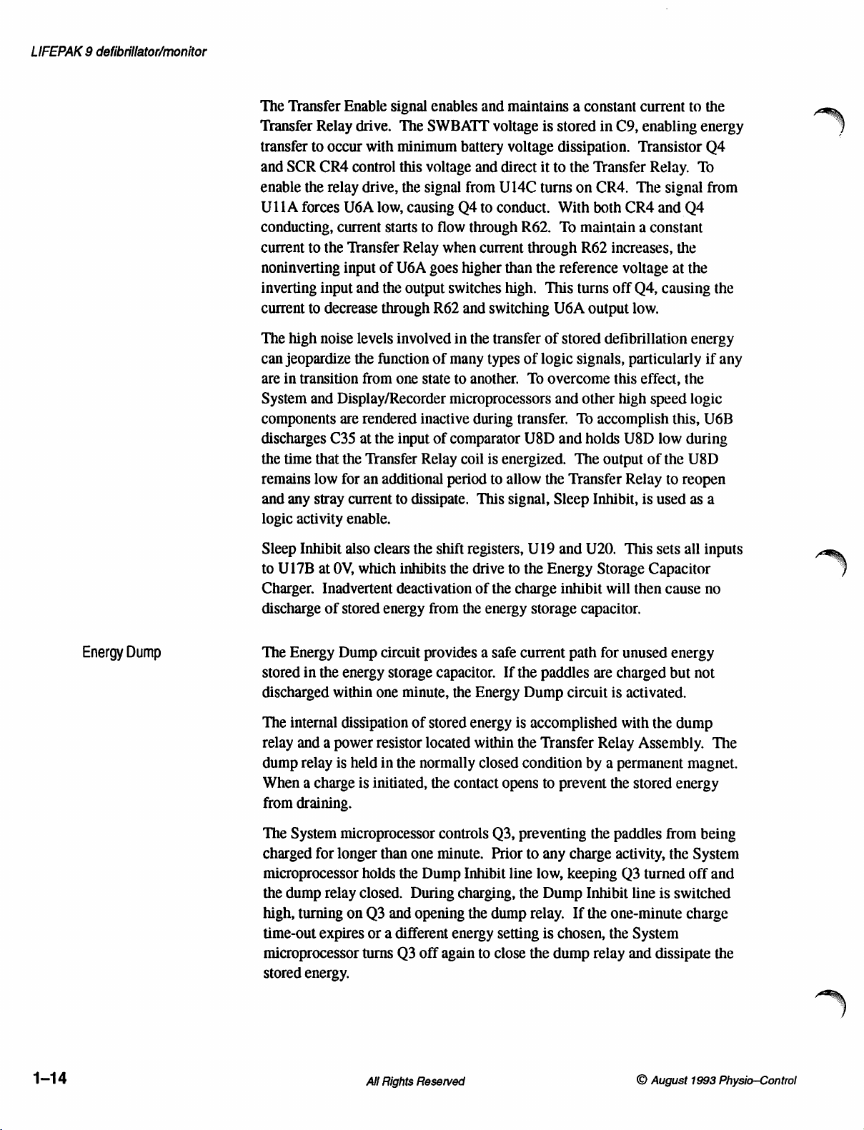
LIFEPAK 9 defibrillator/monitor
The
Transfer
Transfer
transfer
and
enable
ULIA
conducting,
current
noninverting
inverting
current
The
can
are
System
components
discharges
the
remains
and
logic
Relay
to
occur
SCR
CR4
the
relay
forces
current
to
the
input
to
decrease
high
noise
jeopardize
in
transition
and
Display/Recorder
are
C35
time
that the
low
any
stray
activity
Enable
drive.
with
control
drive,
U6A
low,
starts
Transfer
input
of
and
the
through
levels
the
function
from
rendered
at
the
Transfer
for
an
additional
current
enable.
signal
enables
The
SWBATT
minimum
this
voltage
the
signal
causing
to
Relay
U6A
goes
output
R62
involved
of
one
state
inactive
input
of
Relay
to
dissipate.
and
maintains a constant
voltage
battery
Q4
flow
when
higher
switches
and
in
many
to
microprocessors
comparator
coil
period
voltage
and
direct
from
U14C
to
conduct.
through
current
than
high.
switching
the
transfer
types
another.
during
is
energized.
to
allow
This
signal,
R62.
through
of
To
transfer.
U8D
is
stored
in
C9,
dissipation.
it
to
the
Transfer
turns
on
CR4.
With
both
To
maintain a constant
R62
increases,
the
reference
This
turns
off
U6A
output
of
stored
defibrillation
logic signals,
overcome
and
and
the
Transfer
Sleep
this
other
To
accomplish
holds
The
output
Inhibit,
high
current
enabling
Transistor
The
CR4
voltage
Q4,
low.
particularly
effect,
U8D
Relay
is
Relay.
signal
and
Q4
the
at
causing
the
speed
this,
low
during
of
the
to
reopen
used
to
To
the
energy
logic
U8D
as
the
energy
Q4
from
the
if
any
U6B
a
Energy
Dump
Sleep
Inhibit
to
U17B
Charger.
discharge
The
Energy
stored
discharged
The
internal
relay
and a power
dump
relay
When a charge
from
draining.
The
System
charged
microprocessor
the
dump
high,
turning
time-out
microprocessor
Stored
also
at
OV,
Inadvertent
of
stored
Dump
in
the
energy
within
dissipation
is
held
microprocessor
for
longer
relay
on
expires
energy.
clears
the
shift
which
inhibits
deactivation
energy
circuit
one
resistor
in
is
initiated,
than
holds
closed.
Q3
or a different
turns
from
provides a safe
storage
and
capacitor.
minute,
of
stored
located
the
normally
the
one
the
Dump
During
opening
Q3
off
registers,
the
drive
of the
the
energy
the
Energy
energy
within
closed
contact
controls
minute.
Inhibit
charging,
the
energy
again
to
U19
to
the
charge
storage
current
If
the
Dump
is
accomplished
the
condition
opens
Q3,
preventing
Prior
to
line
the
dump
relay.
setting
close
the
and
U20.
Energy
inhibit
capacitor.
path
paddles
circuit
Transfer
by a permanent
to
prevent
any
charge
low,
keeping
Dump
is
Inhibit
If
chosen,
dump
This
Storage
will
for
unused
are
charged
is
activated.
with
Relay
the
the
paddles
activity,
Q3
the
one-minute
the
relay
and
sets
all
Capacitor
then
cause
energy
but not
the
dump
Assembly.
stored
energy
from
the
turned
line
is
switched
System
dissipate
inputs
no
The
magnet.
being
System
off
and
charge
the
1-14
All
Rights
Reserved
©
August
1993
Physio—Control
Page 29
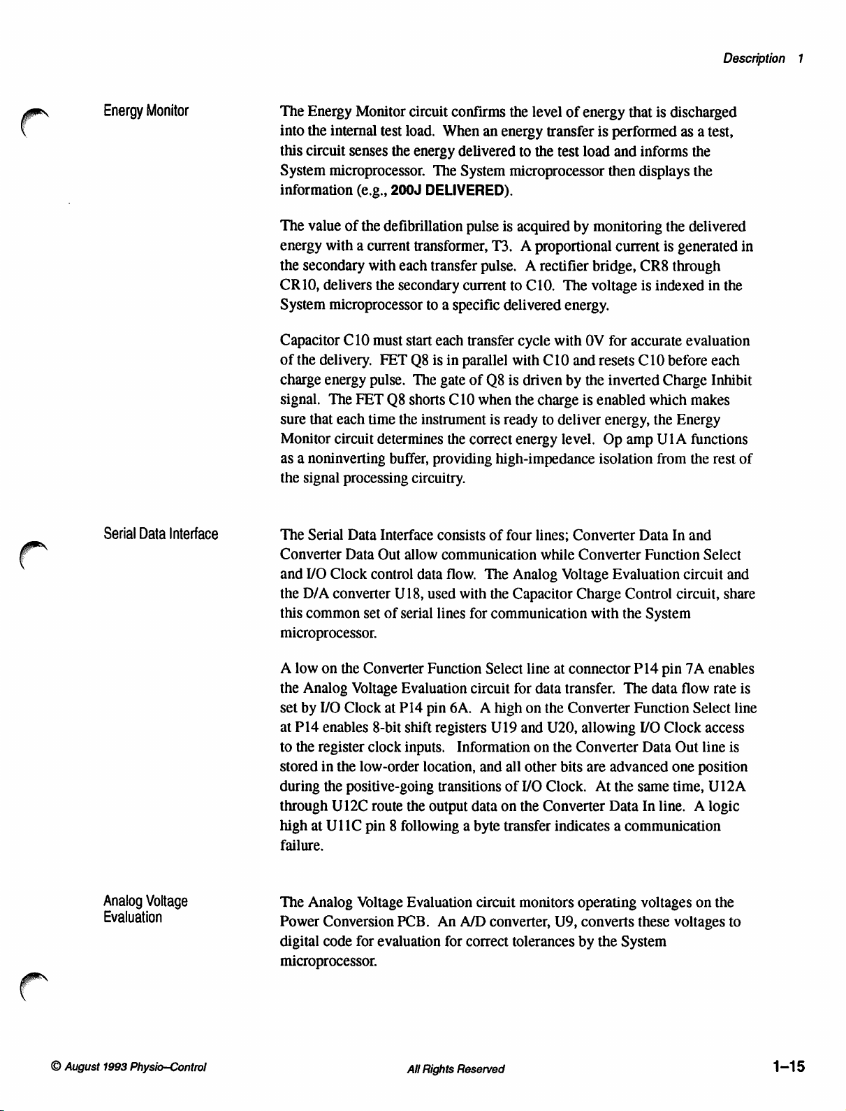
Description
1
Energy
Monitor
The
Energy
into
the
this
circuit
System
information
The
value
energy
the
secondary
CR10,
System
Capacitor
of
the
charge
signal.
sure
that
Monitor
as a noninverting
the
signal
Monitor
internal
microprocessor.
with a current
delivers
microprocessor
delivery.
energy
The
each
circuit
test
senses
(e.g.,
of
the
defibrillation
with
the
C10
must
FET
pulse.
FET
time
determines
processing
circuit
load.
the
energy
The
200J
DELIVERED).
transformer,
each
transfer
secondary
to a specific
start
each
O8
is
The
O8
shorts
the
instrument
buffer,
providing
circuitry.
confirms
When
delivered
System
pulse
current
the
an
energy
microprocessor
is
acquired
T3. A proportional
pulse. A rectifier
to
delivered
transfer
in
parallel
gate
of
C10
the
correct
with
O8
is
when
the
is
ready
energy
high-impedance
level
transfer
to
the
C10.
cycle
C10
driven
charge
to
of
energy
test
load
by
monitoring
bridge,
The
voltage
energy.
with
OV
and
by
the
is
deliver
level.
that
is
performed
and
informs
then
displays
current
CR8
is
for
accurate
resets
C10
inverted
enabled
energy,
Op
isolation
which
the
amp
is
discharged
as a test,
the
the
the
delivered
is
generated
through
indexed
evaluation
before
Charge
makes
Energy
UIA
functions
from
the
in
in
the
each
Inhibit
rest
of
Serial
Data
Interface
Analog
Voltage
Evaluation
The
Serial
Data
Interface
Converter
and
the
D/A
this
microprocessor.
A
low
the
Analog
set
by
at
P14
to
the
stored
during
through
high
failure.
The
Power
digital
microprocessor.
Data
I/O
Clock
converter
common
on
the
Voltage
I/O
Clock
enables
register
in
the
low-order
the
positive-going
U12C
at
U11C
Analog
Voltage
Conversion
code
for
Out
control
set
Converter
8-bit
clock
route
pin 8 following a byte
evaluation
allow
data
U18,
used
of
serial
Function
Evaluation
at
P14
pin
shift
inputs.
location,
the
output
Evaluation
PCB.
consists
communication
flow.
lines
registers
transitions
An
for
of
four
The
Analog
with
the
Capacitor
for
communication
Select
circuit
6A. A high
Information
data
A/D
correct
for
U19
and
all
of
on
transfer
circuit
converter,
tolerances
lines;
Converter
while
Converter
Voltage
Charge
with
line
at
connector
data
transfer.
on
the
Converter
and
U20,
allowing
on
the
Converter
other
bits
are
YO
Clock.
the
Converter
monitors
At
indicates a communication
operating
U9,
converts
by
Data
Evaluation
Control
the
P14
The
Function
VO
advanced
the
same
Data
voltages
these
the
System
In
and
Function
System
data
Data
In
line. A logic
circuit
circuit,
pin
7A
flow
Select
Clock
Out
line
one
position
time,
on
voltages
Select
access
and
share
enables
rate
is
line
is
U12A
the
to
©
August
1993
Physio—Control
All
Rights
Reserved
1-15
Page 30
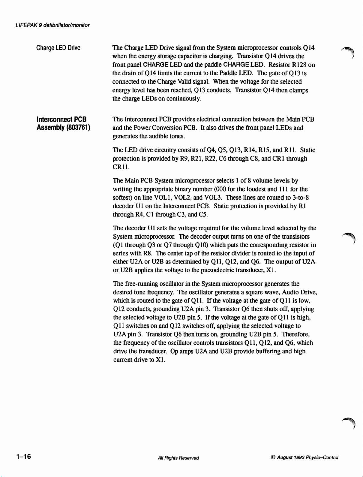
LIFEPAK 9 defibrillator/monitor
Charge
Interconnect
Assembly
LED
Drive
(803761)
PCB
The
Charge
when
the
energy
front
panel
the
drain
of
connected
energy
the
charge
The
and
generates
The
protection
CRII.
The
writing
softest)
decoder
through
to
level
LEDs
Interconnect
the
Power
the
LED
drive
is
Main
PCB
the
on
line
U1
R4,
LED
Drive
signal
storage
CHARGE
Q14
the
has
LED
limits
the
Charge
been
reached, Q 13
on
continuously.
PCB
provides
Conversion
audible
provided
appropriate
on
Cl
tones.
circuitry
by
System
microprocessor
binary
VOLI, VOL2,
the
Interconnect
through
C3,
from
capacitor
and
the
current
Valid
signal.
electrical
PCB.
It
consists
R9,
of
R21,
number
and
PCB.
and
CS.
the
System
is
charging.
paddle
to
the
When
conducts.
microprocessor
Transistor
CHARGE
Paddle
LED.
the
voltage
Transistor
connection
also
drives
the
Q4,
QS,
Q13,
R22,
C6
through
selects 1 of 8 volume
(000
for
the
VOL3.
These
Static
protection
LED.
The
for
between
front
panel
R14,
R15,
C8,
and
loudest
lines
are
is
controls Q 14
Q14
drives
Resistor
gate
of
the
selected
Q14
then
the
LEDs
and
R11.
CRI
levels
and
111
routed
provided
the
R128
Q13
is
clamps
Main
PCB
and
Static
through
by
for
the
to
3-to-8
by
R1
on
The
decoder
System
(Q1
series
either
or
The
desired
which
Q12
the
Q11
U2A
the
drive
current
microprocessor.
through
with
U2A
U2B
free-running
tone
is
conducts,
selected
switches
pin
frequency
the
drive
U1
sets
Q3
or
R8.
The
or
U2B
applies
the
oscillator
frequency.
routed
to
grounding
voltage
on
and
3.
Transistor
of
the
transducer.
to
X1.
the
voltage
The
Q7
through
center
tap of
as
determined
voltage
the
gate
to
Q12
U2B
to
in
The
of
U2A
pin
switches
Q6
then
oscillator
Op
amps
required
decoder
the
the
oscillator
O11.
controls
output
Q10)
which
the
resistor
by
Q11,
piezoelectric
System
generates a square
If
the
pin
3.
Transistor
5.
If
the
off,
applying
turns
on,
transistors
U2A
and
for
the
volume
turns
on
one
puts
the
corresponding
divider
Q12,
microprocessor
voltage
voltage
grounding
is
routed
and
Q6.
transducer,
at
the
Q6
then
at
the
gate
the
selected
U2B
Q11,
U2B
provide
buffering
level
selected
of
the
to
The
output
X1.
generates
wave,
gate
of
shuts
of
Q11
voltage
pin
5.
Q12,
and Q6,
by
the
transistors
resistor
the
input
of
U2A
the
Audio
Q11
off,
Therefore,
Drive,
is
low,
applying
is
high,
to
which
and
high
in
of
1-16
All
Rights
Reserved
©
August
1993
Physio-Control
Page 31
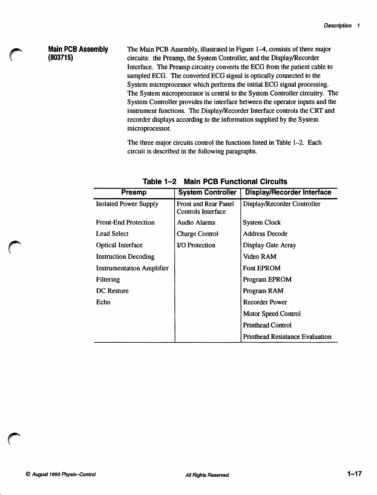
Main
PCB
(803715)
Assembly
The
Main
PCB
Assembly,
circuits:
Interface.
sampled
System
The
System
instrument
recorder
microprocessor.
The
circuit
the
Preamp,
The
Preamp
ECG.
microprocessor
System
Controller
three
is
The
microprocessor
functions.
displays
major
described
the
circuitry
converted
which performs
provides
The
according
circuits
in
control
the
illustrated
System
is
the
Display/Recorder
to
following
in
Controller,
converts
ECG
signal
central
the
to
interface
information
the
functions
paragraphs.
Figure
the
the
the
between
1-4,
and
the
ECG
from
is
optically
initial
ECG
System
the
Interface
supplied
listed
consists
Display/Recorder
Controller
operator
in
of
three
the
patient
connected
signal
processing.
circuitry.
inputs
controls
by
Table
the
1-2.
the
System
cable
to
the
CRT
Each
Description
major
to
The
and
the
and
1
(©
Preamp
Isolated
Front-End
Lead
Optical
Instruction
Instrumentation
Filtering
DC
Echo
Power
Protection
Select
Interface
Decoding
Restore
Table
Supply
Amplifier
1-2
Main
System
Front
Controls
Audio
Charge
VO
Protection
PCB
Controller
and
Rear
Interface
Alarms
Control
Functional
Display/Recorder
Panel
Display/Recorder
System
Address
Display
Video
Font
Program
Program
Recorder
Motor
Printhead
Printhead
Circuits
Clock
Decode
Gate
RAM
EPROM
EPROM
RAM
Power
Speed
Control
Resistance
Interface
Controller
Array
Control
Evaluation
©
August
1993
Physio—Control
All
Rights
Reserved
1-17
Page 32

994
NOISH3ANO
S3HOUMS
defibrillator/monitor
9
LIFEPAK
HAMOd
NIV
OBLNOO
HadSNYHL
OO
volvrimandaa
o
し
STaNVd
SEN
34040
jaNva
10003
eram
|,
994
:
el]
es 83040938
ο
É
É
É
5/5
als
olo = |
3 3 É
fa
93go2zg É |
aj"
—|—
— — — — —
|
1
|
;
U
a
|
1
]
I
|
|
i
БЫ
3owadauNi
|
| |
ㅣ
|
|
|
]
ョ
Agd
O31Wdvivun | HOLNTE
3NHO
03)
3080
037
|
TAWA
HOLINON
JIOVN3
1831035
TÍ
NDOJHALNÍ
LIGIHNI
GNVA
————————n1
MS
DHD
019898
|
anna
ELES)
Wa
】
HOLM)
[60070
3480
0100
(6-1)
SVO
osa
이
30UVHI
ONAS
HEMOd
MS
UMd
ον
U3ISNVUL
5Э45МУЗА
HIGAVÁ
SOUVHO
3OHYHO
TIGOVd
6
ο
同
A
LAN
Gola]
—
| — —
|
13934
cen
HOSSaOOUdOHOIN
N
V
à
|
E
AG
E | NOlO313S13dALov3aHLNI8d
3
Zi
Le
3
+
1
Е
|
TMP,
у
|
—
|
|
|
|
|
ei
l'ammvis
x
[e]
X1
ft
!
|
|
wa
le
|
一
[susu
—
(00
(so)
NI
a
ms
55
NI
L4IHS
Ni
VIVO
Hdl
QVOT
3SN3S
1N3BBno
3dALQVIHINISO
93335
GHA
NOLLVITIVAS
JONVISISIU
ανΒΗΙΝΙΜά
|
39N3S
INIGUNO
BOLON
1nO
dgWV3dd
THING
一
一 一 一 一 一 一
32
US
=
dWV ヨ dd
TodlNoo
vd
FILLVIOANON
>
dezn
pooHoyAla
WaIsAS
WOYdI
хе
00001
013838
Se
AVY
31VO
n
—z
ao
QY3HINiBd
QY ヨ HLNIHd
HIMOd
43040034
het
OVAHINIVA
一
一
un
|
0900
exes
vezn
»
zv
D
I
sos
4-0)
a
m
Få
нозезоонаоной
d ヨ QHOO ヨ HAVTdSIQ
M
po)
때
圖
一 十 一 一 一 一
|
|
|
1
AS1+
|
|
|
|
|
|
|
|
|
|
'
|
|
|
|
|
0910705-
in
ο.
T
一
1
atadas
намоа
|
ROvdUBINI
WOLLdO
|
|
we
OCIA
600
AVIV
31V9
Avidsla
NOISHIANOD
INR 7 HILHSANOO
430409
mm
00
»
|
=
N
av
auolsa
(1-0) v 300930 [ (1-0)
SL
ron
1081
tou
一
一 一 一 一 一 一 一 一 一 一 一 一 一 一 一 一 一 一
po
|
İ—>
ems
HLBUH
ZHNS | 2019
dASI-
+
AZI-
(91-0)
SIn そ in'en
SS3HCOV
нию
~
W3LSAS
|
waLindwy
NOLIVINZIANH
SN!
LE
—
0H93
VO
(he
oniva.nia
=
20005
Co)
qa
(0)
ava
woud
NOA
RR
_
し
IdsIG
|
|
|
|
|
|
|
|
;
一
|
|
|
|
|
|
sz100w4
NOOT-MINO
—
37072
ANGUYA
Diagram
Block
PCB
Main
1-4
Figure
Ti
to
HIMOd
UN
OL
39VJH ヨ 1NI
3/AV
1
NOLL9310Hd
UN3-1NOYA
|
ο
a
Physio-Control
1993
August
©
Reserved
Rights
All
1-18
Page 33

Description
1
Preamp
Isolated
+15Vdc,
Preamp
Power
+12Vdc,
circuitry.
modulator
24kHz.
positive
isolated
the
circuitry
small,
Front-End
VSP3
provided
the
voltage
Lead
U33
controls
between
the
conducts;
selected,
output
The
half
+15V
isolated
from
U37
limit
by
Preamp.
when
Select.
is
loaded
relay
patient
state
of
paddles
analog
of
U33.
Supply.
-15Vdc,
The
US.
Capacitor
secondary
of
the
ac
supply.
-15V
supply.
the
heavier
doubles
Protection.
the
R131
K1
as a regulated
input
and
Diodes
Kl
is
switched
To
select
with
the
K1,
U43A,
leads
to
the
are
switch
current
CR18, CR19,
The
+5
drive
for
C12
of
T1
input
waveforms
The
negative
Regulators
loads.
To
protect
to
R132
which
between
decoded
and
or
paddles,
desired
selected
U42
selects
Isolated
Vdc,
and
is
2mA.
to
analog
position.
when
Power
and
transformer
R28
applied
ac
U38
Since
supply
against
Isolation
guard
and
the
leads
paddles
data
from
switches
U33
causes
Q9
the
Supply
-12Vdc
set
to
are
waveforms
the
CR28
Patient
conducts.
lead
supplies
T1
is
generated
the
frequency
full-wave
stored
at
C87,
are
and
U39
isolate
+5
Vdc
loads
and a reference
voltage
against
mode.
and
counter
(1,II,1I,
for
excessive
clamp
the
different
U32.
U42
Q8
or
leads
surges,
the
and
Q9
If
or
provides
required
by
between
bridge
the
are
patient
CR20.
forming
stored
at
more
are
synchronous
source.
VSP1
paddles
charge
differential
patient
Flip-flop
U41.
to
conduct,
selected
leads
STD)
requested
the
isolated
by
the
pulse-width
12kHz
The
the
C86,
forming
sensitive
through
input
is
input
paddle
leads,
latch
U33
To
select
switching
when
Q8
are
by
and
and
to
the
Optical
through
synchronize
a
+1mV
timer
and a fixed-freguency
System
train
The
interrupting
The
isolation.
train
Interface.
the
the
optical
the
ECG
calibration
to
transmit a pulse
microprocessor
at
U4
pin
4.
System
16kHz
as
microprocessor
the
output
pulse
Comparator
it
passes
Command
conversion,
signal.
drives
to
the
pulses
interface
to
perform
select 1 of 5 patient
The
System
of
variable
period
(540Hz).
enables
with a CLR
the
U34D
Instruction
U4
controls
signal
infrared-emitting
performs
Decoding
from
the
three
microprocessor
duration
to
start
the
(approximately
The
variable-duration
counting,
count
as
shown
diode
waveform
circuit,
System
microprocessor
different
cable
uses
creating a 16kHz
of
the
pulse
at
TP6
in
U7
conditioning
U32
functions:
leads,
and
an
internal
80ms
pulse
train
by
in
Figure
providing
for
the
and
U33.
to
1.2ms)
from
1-5.
pulse
pulse
pass
induce
the
pulse
©
August
1993
Physio—Control
All
Rights
Reserved
1-19
Page 34

LIFEPAK 9 defibrillator/monitor
TP6
TP17
ua
TP19
oV
TP4
e
———
+»!
VARIABLE
i
| |
Le
1200
PRECISIO
|
1852u»
(540Hz)
to
18001
SLOPE
DA
AP
—
——>»İ
ef
ΩΩ
ΧΧΧ
|
|
|
ke
—ECHO
PROPORTIONAL
PERIOD"
TO
NEGATIVE
==
VOLTAGE
Å
|
AT
TP20
+»!
VARIABLE
|
|
İİ
|,|,
一 一 一
lat
DR
|
一
ασ.
LOGIC
LEVELS
Instruction
microprocessor
The
number
particular
application
conversion
detected
the
ECG
edge
of
initiated
Flip-flop
the
pulses
of
the
(pins
Because
about
command
Decoding.
of
command
of a specific
to a digital
by
U31A
conversion.
the
first
with
every
U36A
from
pulse
train
6,
5,
3,
and
of
the
1.5ms
and
signals.
are
pulses
the
timing
Instrumentation
16mV
p-p
maximum
U44A
and
U44B
by
RN2
pins 1 and
the
differential
U44B.
outputs
This
of
common-mode
through
patient
analog
lead
signal
common-mode
U44A
signal
switch
(LL)
Figure
The
coded
1-5
by
pulse
the
represents a binary
function.
Each
preamp
equivalent.
which
responds
Monostable
pulse
and
clears
pulse
on
the
and
counter
pulse
causes
4).
Subsequent
of
train
the
RC
U32
(see
five-stage
network
sends a positive
These
command
Amplifier.
and
together
2,
R144,
and
The
requires
form a differential
and
rejects
signal
and
U44B
through
is
then
inverted
U41
and
cancelling
common-mode
Preamp
number
train
Timing
commands
of
pulses
number
set
of
pulses
setup,
and
initiation
The
rising
edge
by
sending a pulse
multivibrator
U31A
so
pulse
train.
that
U31B
ECG
form a five-stage
TP17,
Figure
counter
edges
count
R101
edge
to
signals
typical
amplification
and
U33,
select
ECG
to
up
C74,
latching
signal
for
input
RN2
pins 3 and
the
common-mode
(primarily
voltage
and
K1.
Relay
60Hz)
dividers
amplified
K1
routes
signals
from
as
listed
which
corresponds
performs
of
ECG
of
the
to
U34A.
detects
conversion
counter
1-5).
The
load
from
from
the
U31B
the
between
at
U41
further
amplifier
4.
Op
amp
signal
is
generated
R148
by
U35D
the
at
the
the
System
in
Table
two
tasks:
signal
first
pulse
the
that
first
the
preset
times
decoded
leads
and
signal
with
U44D
from
and
and
signal
patient
1-3.
to
a
is
This
initiates
falling
is
not
responds
rising
edge
preset
inputs
inputs.
out
at
and
paddles.
U42
is
processing.
the
gain
amplifies
U44A
and
from
the
R149.
passes
to
the
source.
The
unused
to
set
1-20
All
Rights
Reserved
©
August
1993
Physio-Control
Page 35

Description
1
Pulses
atTP17
ma
YN
bh
ón
JO
DO
©
pe
=
=
Se
WN
S|
Det
S|
AA
pudo
=|
WON
ーー
CTO
DN
=
NON
N
Table
Pulse
Duration
AtTP6(ms)
64
128
192
256
320
384
448
512
576
640
704
768
832
896
960
1024
1088
1152
1216
1280
1344
1408
1-3
Preamp
Result
Not
used
Not
used
Not
used
Lead
III
Lead
II
Lead
I
on
Preamp
Std
Lead
III + Cal
Lead
II + Cal
Lead I +
Cal
Std + Cal
Lead
III + Leads
Lead
II + Leads
Lead I +
Std + Leads
Lead
Lead
Lead I +
Leads
Coil
III + Cal + Leads
II + Cal + Leads
Cal + Leads
Std + Cal + Leads
Lead
III + Paddles
Not used
Not
used
Pulse
Coil
Coil
Drive
Coil
Drive
Drive
Coil
Coil
Widths
Setup
Drive
and
and
and
Coil
Coil
Drive
Coil
Drive
Drive
Drive
and
Switch
Switch
Switch
Switch
Drive
and
and
and
Switch
and
Smooth
Smooth
Smooth
Smooth
and
Switch
Switch
Switch
Switch
Smooth
Smooth
Smooth
Smooth
Smooth
©
August
1993
Physio—Control
The
+1mV
calibration
microprocessor
signal
is
applied
offset
of
approximately
input
stages.
Filtering.
operation.
op
amps
function
blocking
U45A
Filtering
The
U44C,
as a high-pass
freguencies
removes
filter.
DC
Restore.
offset
originating
The
signal
is
which
sets
U33
to
U44A
pin 2 and
+1mV
provides a uniform
preamp
U45D,
freguencies
below
DC
from
All
filtering
U45A,
filter
for
0.024Hz.
above
Restore
switch
Rights
Reserved
created
by
pin 7 high.
U44B
to
the
input
signal
is
performed
and
U45B.
Preamp,
In
the
200Hz.
circuit
compensates
smoothing,
an
instruction
When
pin
6.
This
without
from
U43A
adds a differential
changing
bandwidth
by
two
stages
In
the
first
stage,
DC
Restore,
second
U45B
defibrillation,
and
stage,
functions
for
any
or
the
System
closes, a -SV
the
gain
during
normal
centered
U44C
and
switch
low-pass
smoothing,
filter
as a 540Hz
unwanted
motion
artifact.
offset
of
the
around
U45D
notch
dc
1-21
Page 36

LIFEPAK 9 defibrillator/monitor
This
preserves
controls
Instrumentation
conversion.
from
+1V
any
transient
Under
to
+11V.
the
dc
offset
signals
Amplifier
normal
level
required
to
prevent
from
falsely
operation,
by
the
the
high
amplifying
the
A/D
conversion
Echo
circuit.
potential
the
dc
gain
level
dc
DC
of
the
input
level
Restore
for
at
TP19
is
Switch
offset
This
Table
selected
Q11
parallel
above
Transient
U45C
when
negative
positive
filter
inducing
signal
and
When
eliminate
QUIK-LOOK
Table
loaded
Analog
high-pass
smoothing
voltages
function
1-3,
lead.
to
conduct.
with
40Hz.
functions
the
bias
bias
to
prevent
DC
through
U45D,
PADDLES
1-3,
so
switch
is
the
when
switching
is
initiated
pulses
signals
voltage
motion
pulse
that
filter,
12
thru
When
Q8
Q11
R165.
to
limits
Because
associated
as a window
at
its
to
the
noninverting
the
inverting
very
short
Restore.
high-pass
the
signal
is
selected,
artifact
mode. A command
20),
turning
the
next
U43B
then
and
limiting
process
when
20) turns
switches
changes
of
with
input
exceeds
input.
spikes
The
output
filter
passband
introduced
Q9
clock
pulse
closes,
the
of
limiting
from
one
lead
the
appropriate
on
Q8
on,
C90
the
high-pass
R161,
this
defibrillation
comparator
+2V.
input
of
C104
(such
an
of
U45C
U44C
and
to
5Hz.
further
passband
by
the
pulse
selects
on.
When
at
pin 6 switches
bringing
ECG
signal
the
response
(I,
Il,
number
or
Q9
and
discharges
filter
by
filter
limits
are
sensed
and
responds
Resistors
U45C;
and
U45D.
R151
an
internal
drives
R171
transistor
Resistor
limiting
paddles
paddles
Q9
conducts,
R155
in
passband
of
the
Ill,
or
STD)
of
pulses
switches
from
switching
the
R172
function
pacing
when
U42
+12V,
signal
by
op
with a positive
and
and
R143
as a low-pass
spike)
Q10,
R160,
is
required
used
mode,
flip-flop
the Q output
parallel
to
with
above
preamp
to
another.
(see
to
the
causing
R161
in
passband
amp
U45C.
R147
apply
apply
from
routing
with
U44C
to
in
the
(see
U36B
high.
R165
2Hz.
to
dc
to
output
a
a
the
is
in
the
1-22
Echo.
from
from
back
signal
microprocessor
the
The
ECG
the
System
the
System
to
the
System
(see
Figure
pulse-delay
signal
is
converted
microprocessor.
microprocessor
microprocessor
1-6).
When
(across
period
All
Rights
an
opto-isolator),
to a number.
Reserved
to a pulse-delay
The
time
is
received
is
proportional
the
echo
pulse
the
from
until
is
sent
System
period
on
when
the
convert
the
“echo”
to a sample
back
to
microprocessor
©
command
pulse
of
the
the
System
August
command
is
sent
ECG
converts
1993
Physio-Control
Page 37

U34A
TRIGGER
VOLTAGE
AT
TP19
PIN 4 |
PULSE
ト - ECHO
TP4
TIME
En
|
| |
|
Description
1
>
PERIOD» | |
거
———
he—
13
—».
-一
i
RAMP
ECG
conversion
passes
sends a trigger
-6.3V
conversion.
The
U35B,
period.
signal
when
output
+5V
U35C.
discharge
Figure
While
trigger
Q6,
R100
which
to
U32
at
the
output
ECG
signal
U35C,
The
track
at
U3SB
comparator
to
-12V.
line
and
When
from
1-6).
the
track
pulse
and
allows
and
R99.
discharges
pin
pulse
07,
R122
Q7
from
TRACK
Figure
begins
2.
of
from
and
phase
to
charge
U34A
This
turns
C76,
and
U31A.
the
+15V
The
C72
1-6
when
The
rising
every
1.8ms
U3SA,
U35A
providing a signal
passes
C76.
This
begins
sampling
receives
voltage
provide a constant
This
ramp
output
passes
off,
the
discharge
circuit
This
supply
of
through
Echo
Period
the
pulse
train
edge
of
the
to
U34A.
to a track
circuit
when
the
constant
is
drives
to
comparator
opto-isolator
controls
O7
conducts,
capacitor
trigger
to
the
gate
current
current
produces a ramp
tracking,
the
output
charge
C72
U34C
at
the
output
first
pulse
The
ECG
range
and
ramp
the
duration
which
C76.
The
pulse
(every
of
Q7
turning
source
comparator
to
source
of
U34A
through
controls
U6
and
creates
of
counter
clocks
signal
of
output
U31A,
is
offset
-1V
to
-11V
circuit
ramp
causes a linear
consisting
of
causes
phase
1.8ms),
Q7
the
inverting
from
U34A
to
-12V,
voltage
the
on-time
the
the
the
driving
off.
U35C
receives
turns
dividers
echo
U4
which
to
for
of
echo
ECG
starts
the
The
input
(see
the
off
of
Q6,
signal.
of
©
August
1993
Physio-Control
The
duration
long
the
When
the
switches
Causes
and
the
allows
of
output
ramp
to
-12V,
output
the
the
ramp
of
U34C
output
echo
of
presenting
of
U34C
signal
All
output
is
low
U35C
to
to
Rights
of
the
and
sets
reaches
this
voltage
switch
be
coupled
Reserved
track
to
high
and
the
duration
OV,
the
at
the
impedance
through
ramp
circuit
of
the
output
inverting
of
comparator
input
which
opto-isolator
determines
echo
period.
of
U34C.
turns
U6.
U34B
on
how
This
Q6
1-23
Page 38

LIFEPAK 9 defibrillator/monitor
System
Controller
The
System
keypad
The
central
with
external
the
ECG
These
filtering
U30
communicates
two
asynchronous
addition
are
created
and
echo
ECG
and
to
the
Controller
sends
component
RAM
pulse
samples
display
three
by
routing
U20.
The
operating
32k x 8
including
contains
decoding
pins
12,
Multi-vibrator
System
watchdog
microprocessors
consisting
short;
R47
software
EPROM.
the
calibration
the
lithium
is
performed
13,
and
U26
microprocessor
circuit
of
R46
and
C33
circuit
commands
and
widths
are
on
with
serial
8-bit
DO
Battery-backed
energy
14.
and
monitors
if
the
pulse
and
C31
detect a pulse
to
of
this
ROM
to
then
sent
the
CRT.
the
Display/Recorder
transmit
I/O
through
for
the
constants.
cell
by
3-to-8
flip-flop
and
the
the
width
is
used
receives
the
circuit
devices.
sample
ports
System
and
Display/Recorder
1.8ms
input
CRT,
is
System
The
values
to
the
Display/Recorder
and
receive
contained
D7
in
parallel
Controller
RAM
DIP
(Dual
real-time
decoder
U16
form
preamp
is
out
by
U26
width
that
signals
recorder,
System
for
U28A
U25
the
trigger
of
tolerance.
to
detect a pulse
is
from
the
and
defibrillation
microprocessor
microprocessor
the
CRT
and
microprocessor
microprocessor
lines
at
pins
12
in
U30,
16
extra
out
to
octal
is
contained
provides
In-line
clock
using
watchdog
microprocessor.
too
data
Package)
information.
only
the
circuit
pulse
and
An
RC
width
long.
front
panel
circuits.
U30,
converts
recorder.
(U1)
through
and
13.
output
latches
outputs
U19
in
U27,
storage,
socket
Address
at
for
the
The
resets
both
network
that
together
for
In
lines
and
a
U28B
is
too
Controller
needed.
microprocessor
of
tolerance,
conduct,
U18A,
and
Front
panels
function(s)
panels
rows
multiplexer,
column
Audio
off
and
PCB
U46
This
protects
the
pulling
and
U17A)
the
Display/Recorder
and
Rear
are
distributed
to
activate.
are
arranged
(RAS 1 through
providing a high
switch.
Alarms.
controls
produces
an
monitors
activity.
output
the
Panel
The
the
audible
the
+5V
supply
the
RAM
memory
If
the
controller
at
NOT
CEO
switches
voltage
goes
in a matrix
System
volume. A piezoelectric
at
R45
to
the
RESET
microprocessor.
Controls
to
the
Input
3).
The
tone
Interface.
System
from
of
five
System
logic
microprocessor
in
response
low.
microprocessor
the
level
and
causes a system
and
prevents spurious
detects
This
lines
pushbuttons
columns
microprocessor
for
that
high
and
low
logic
for
the
System
Signals
which
on
(CAS 1 through
each
row
switches
transducer
to
input
from
the
from
reset
as
+5V
supply
causes
level
Q5
to
(through
microprocessor
the
front
determines
the
front
and
5)
and
functions
and
the
on
the
as
sensing
audio
alarm
the
Interconnect
System
a
any
is
out
U23C,
and
what
rear
three
closed
on
rear
and
1-24
All
Rights
Reserved
©
August
1993
Physio-Control
Page 39

Description
1
microprocessor.
provides
pushbutton
eight
microprocessor
Charge
requests
Clock,
Out
CHARGE
System
Data
Conversion
Data
communication.
Following
self-tests
self-test
The
10-bit
converter
converter.
out
four
tone
is
pressed.
volume
lines
levels.
internal
Control.
to
the
D/A
Converter
accomplish
on
the
microprocessor
Out
line.
Status
PCB
In.
The
I/O
the
charge
which
are
fails,
the
energy
of
stored
A/D
converter
shares
If
the
tolerance,
An
internal
frequencies,
Three
The
audio
oscillator.
The
System
converter
Function
keypad
is
sent
Clock
completed
CRT
in
the
System
an
ENERGY
Select,
serial
communication
transmits
to
the
information
back
provides
initiation,
displays
the
energy
(U9)
located
four-line,
microprocessor
oscillator
including
output
microprocessor
U18
Power
to
before
the
serial-communication
FAULT
in
the
the
lines,
is
silenced
on
the
Power
Converter
the
coded
Conversion
on
the
decoding
the
System
synchronous
the
System
the
selected
SERVICE
storage
on
the
capacitor
Power
indicates
message
System
key-click
VOL1
by
turning
initiates
Conversion
Data
with
the
selected
PCB
microprocessor
timing
microprocessor
indicator.
Conversion
is
microprocessor
response
through
off
and
VOL3,
the
System
monitors
PCB.
In,
and
Converter
D/A
converter.
energy
over
the
process
energy
is
monitored
interface with
that
on
over
for
serial
performs a set
is
available.
PCB.
the
energy
displayed.
when
a
produce
charge
The
Data
Pressing
value
from
Converter
the
Power
Converter
Ifa
through
The
the
D/A
stored
I/O
the
of
a
A/D
is
Display/Recorder
Interface
I/O
Protection.
resistors
Additional
on
Display/Recorder
Display/Recorder
data
Display
resolution
microprocessor
receives
microprocessor
displayed
ECG
Display/Recorder
approximately
microprocessor
the
from
sample
and
capacitors
protection
Video
the
PCB
is
not
all
incoming
with
1,
Video
System
Assembly
as
compresses
also
gaps
data
every
are
Electrostatic
is
2,
Controller.
microprocessor
microprocessor
high
discharge
on
all
the
provided
and
Raster
CRT
and
as
the
recorder
ECG
ECG
data
formats
or
is
transmitted
microprocessor
1.8ms.
also
the
overlapping
Other
transmitted
protection
I/O
lines
that
by
6.2V
zener
lines
directed
The
central
U1.
It
receives
and
controls
the
recorder.
resolution,
data
for
the
samples.
ECG
segments.
from
through
data
the
The
for
System
the
data/command
to
the
Display/Recorder
is
provided
connect
diodes,
component
Because
CRT
Display/Recorder
the
Tx
to
the
CR7
to
the
Monitor
of
the
digitized
the
input
the
the
Display/Recorder
display.
CRT
so
microprocessor
serial
communication
bytes
from
by
the
Main
PCB.
through
this
circuit
of
this
CRT
The
waveforms
the
microprocessor
CR9,
PCB.
is
ECG
signal
data
screen
recorder
are
to
the
System
the
to
the
not
line
©
August
1993
Physio—Control
All
Rights
Reserved
1-25
Page 40

LIFEPAK 9 defibrillator/monitor
when
they
are
packets
containing a header
data/command
The
first
four
VO
Gate
Array,
U29,
lines
control
the
required
byte.
lines
driving
operation
for a particular
byte,
listed
in
Table
the
input
of
the
function.
two
ECG
1-4
for
the
recorder.
This
data
sample
bytes,
communicate
Display
PCB.
is
transmitted
and,
if
with
the
The
other
in
required,
a
Display
five
YO
Table
VO
P(50)
P(52)
P(53)
P(54)
P(21)
P(60)
P(61)
P(66)
P(67)
System
16MHz
both
the
2MHz
Address
and
the
functions
devices
in
memory.
1-4
Line
Clock.
square
System
to
A/D
Decode.
writing
as
when
Display/Recorder
Signal
H.RETR
GO
|INCMEM
|TR/CHAR
STROBE
RECORDER
PRINTHEAD
PRINTHEAD
PRINTHEAD
Crystal-controlled
wave
to
and
Display/Recorder
converter
Programmable
to
all
external
an
address
the
Display/Recorder
POWER
CURRENT
TYPE
LOAD
the
Display
U9
on
the
memory
decoder
and
Microprocessor
SENSE
multiple-output
Gate
Array.
microprocessors
Power
logic
array
and
is
programmed
microprocessor
It
Conversion
U9
controls
the
Recorder
VO
Direction
In
Out
Out
Out
Out
Out
In
In
Out
oscillator
also
PCB.
to
addresses
U10
supplies
(U30
the
Gate
enable
Lines
provides
8MHz
and
U1),
reading
Array,
the
different
from
U3.
appropriate
a
to
and
U9
areas
>
1-26
Buffers
devices
buffers
bus
and
Display
many
flip-flops,
only
ECG
additional
U11,
from
the
data
between
the
RAM/ROM
Gate
blocks
etc.). A metalized
those
circuits
memory
timing
U12,
and
U1S5
interaction
bus.
the
Display/Recorder
Array.
of
standard
addressing,
signal
All
with
Buffers
memory
Display
OR
needed
generation.
Rights
Reserved
for a specific
ECG
isolate
the
appropriate
the
Display/Recorder
U12
and
U15
microprocessor,
devices.
Gate
Array
and
AND
gate
layer
added
function:
display
trace
Two
RAM/ROM
control
U29
circuits
on
different
interaction
the
is a
top
of
the
Monitor
generation,
internal
memory
microprocessor.
on
the
Display
custom
(counters,
gate
Gate
IC
containing
multivibrators,
circuits
PCB
video
counters
O
connects
sync
intensity,
August
U11
address
Array,
timing,
and
control
1993
Physio-Control
Page 41

the
timing
during
CRT
The
vertical
256
of
CRT
retrace
Display
and
rows,
and
the
scan
periods.
Gate
horizontal
When a count
of
196,608
Four
Gate
horizontal
Each
another
the
CRT
corresponds
that
corresponds
U21
addresses
(256 x 768)
separate
Array
format
retrace.
trace
generator
memory
screen
to
since
the
for
Video
periods,
Array
the
upper
of
256
memory
the
An
loop
is
created
the
low
to
only
data
each
scan.
RAM
uses
retrace
10
occurs,
occurs,
loops
ECG
internal
uses
for
the
point,
the
high
loaded
(U21)
and
control
an
on
bits
correspond
U29
the
for
signal
11-bit
one
memory
low
by
turning
and
point.
in
and
Font
the
18-bit
the
CRT.
EPROM
Video
counter
The
to
768
RAM
to
lower 8 bits
(U22)
addressing
control
columns
the
initiates a vertical retrace.
gate
array
two
separate
in
memory.
counter
point
the
turning
This
memory
loop
for
of the
video
the
saves
is
initiates
trace
addresses
scan.
on
video
memory
the
the
horizontal
generators
Formatting
each
the
high
point
The
trace
at
the
screen
off
at
the
space
high
point
addressing
during
timing
correspond
(scan
of
the
lines).
When a count
retrace.
in
the
Display
occurs
during
memory
of
the
appearing
location
screen
in
Video
and
the
loop.
scan
location
RAM
low
Description
to
and
on
that
point
1
Serial
communication
Recorder
H.RETR,
Gate
storage
horizontal
H.
microprocessor
GO,
Array
and
RETR
(IRQ1)
=
TR/CHAR
ο
INCMEM,
and
the
Display/Recorder
retrieval
retrace.
Figure
Figure
1-7
between
of
ECG
トド
ce
the
Display
is
accomplished
and
TR/CHAR.
and
character
1-7
shows
UPDATE
Control
|
Line
Gate
Array
by
the
following
These
lines
microprocessor
data
the
control
MESSAGE
©
UPDATE
Timing
in
the
line
to
timing
and
the
Display/
control
enable
the
coordinate
Video
RAM
sequence.
|
lines:
Display
the
during
©
August
1993
Physio-Control
Data
from
memory
horizontal
during
the
Display/Recorder
horizontal
retrace
to
smooth
All
Rights
microprocessor
retrace.
Six
scrolling
Reserved
ECG
of
the
loads
samples
trace
displayed
into
the
update
Video
during
on
the
RAM
CRT.
1-27
Page 42
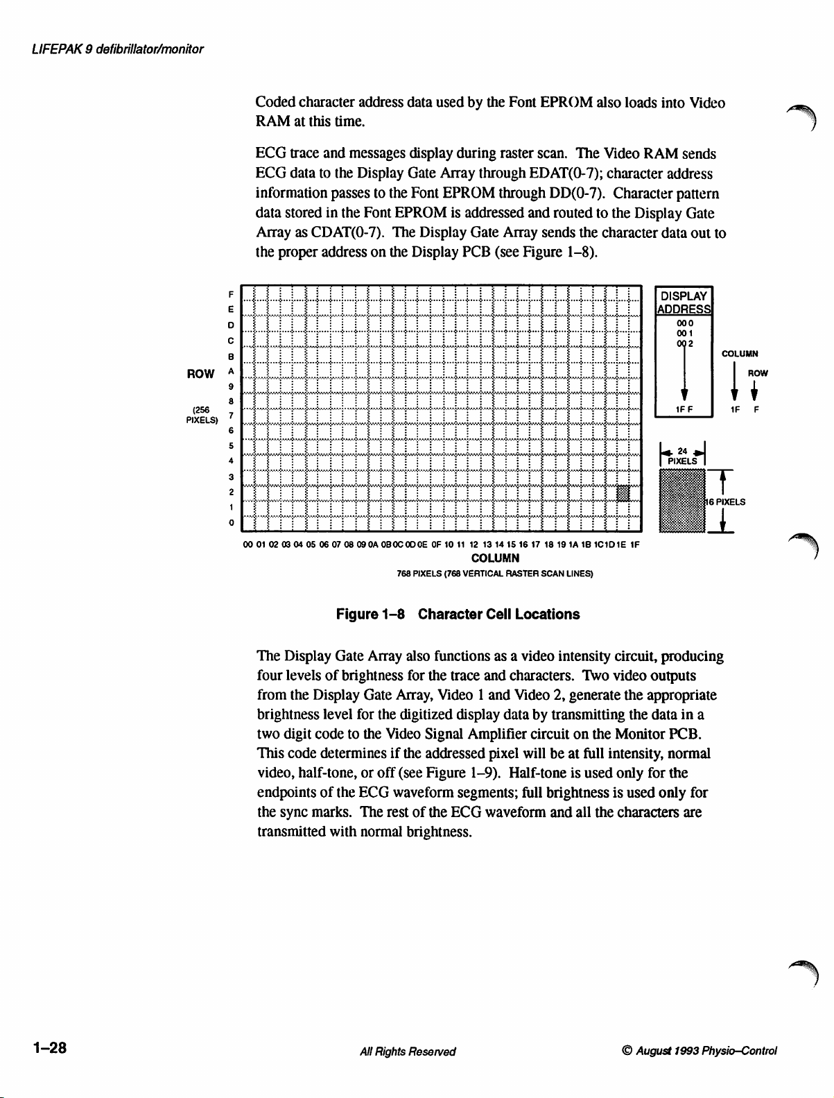
LIFEPAK 9 defibrillator/monitor
ROW
(256
PIXELS)
Coded
RAM
ECG
ECG
information
data
Array
the
ロコ
ロ
O
BO
©
O
ON
BU
O
OSN
00
01
at
trace
data
stored
as
proper
02
03
04
character
this
time.
and
to
the
passes
in
the
CDAT(0-7).
address
05
06
07
address
messages
Display
to
Font
on
08
09
OA
0BOC
data
display
Gate
the
Font
EPROM
The
the
Display
OD
768
PIXELS
used
during
Array
EPROM
is
Display
CE
OF
10
11
(768
by
the
Font
raster
through
through
addressed
Gate
Array
PCB
(see
12
13 14 15 16
COLUMN
VERTICAL
RASTER
EPROM
scan.
The
EDAT(0-7);
DD(0-7).
and
routed
sends
the
Figure
17
SCAN
18 19
1-8).
1A
LINES)
also
Video
character
Character
to
the
character
18
1C1D1E
loads
into
RAM
sends
address
pattern
Display
Gate
data
DISPLAY
ADDRESS
000
001
1FF
24
P
IXELS
m
_
1F
Video
out
to
|
2
=
>
+
E
COLUMN
FT
1+
Е
The
Display
four
levels
of
from
the
Display
brightness
two
This
video,
endpoints
the
sync
transmitted
level
digit
code
code
determines
half-tone,
of
marks.
Figure
Gate
the
1-8
Array
brightness
Gate
for
the
to
the
or
off
ECG
The
with
normal
Character
also
functions
for
the
Array,
Video 1 and
digitized
Video
Signal
if
the
addressed
(see
Figure
waveform
rest
of
the
brightness.
Cell
as a video
trace
and
display
Amplifier
pixel
1-9).
segments;
ECG
waveform
Locations
intensity
characters.
Video
2,
generate
data
by
transmitting
circuit
will
be
at
Half-tone
full
brightness
and
Two
on
full
is
all
the
used
the
circuit,
video
Monitor
intensity,
only
is
producing
outputs
the
appropriate
the
data
PCB.
normal
for
the
used
only
characters
in
a
for
are
1-28
All
Rights
Reserved
O
August
1993
Physio—Control
Page 43

Description
1
VIDEO
1
VIDEO 2 一
|
一
一
一
HALF-TONE
Character
input
data
are
Video
U21.
twelve
Display/Recorder
access.
controlled
NORMAL
Figure
dot
signal.
mapped
RAM.
New
ECG
bytes.
New
by
VIDEO
information
Messages
Trace
Horizontal
data
the
FULL
INTENSITY
1-9
Video
merges
have
to
the
same
and
character
data
is
stored
retrace
microprocessor
storage
Display/Recorder
and
Intensity
with
priority
point
over
on
the
data
during
memory
the
provides
which
microprocessor.
NORMAL
VIDEO
trace
information
waveforms
CRT.
are
stored
horizontal
an
interrupt
signals
address
counter
HALF-TONE
to
when
in a 32k x 8
retrace
to
the
permission
incrementing
create
the
video
the
two
types
static
RAM,
and
consists
for a memory
is
of
of
An
additional
(similar
16 x 32
the
Font
Display/Recorder
Font
EPROM.
with
memory
pixels
wide
displayable
uppercase
and
double-sized
Program
software
is a list
annotated
Program
microprocessor
Additionally,
microprocessor
512
to
ASCII
character
EPROM.
for
to
fit
character
letters
EPROM.
for
the
Display/Recorder
of
codes
recorder
RAM.
as a scratch-pad
all
bulletin
A
in
representing
CODE
bytes
are
used
codes).
cells,
The
microprocessor
32k x 8
256
in
numerals
text.
The
The
with
each
message
EPROM,
characters.
the
screen
set
includes
normal,
inverse,
are
Another
all
Program
SUMMARY
board
screen
character
in
32k x 8
RAM
is
for
storage
cell
content
during
U22,
Each
single-sized
and
normal
microprocessor.
of
the
while
data
stored
of
can
be
configured
accepting
is
updated
horizontal
contains
character
cells
(see
numerals,
boldface
video
EPROM,
words
and
U13
is
used
performing
and
the
in
the
Program
the
character
address
into a matrix
character
is
Figure
video.
display.
U14,
phrases
by
program
Display/Recorder
information
as
needed
retrace.
character
16
contains
Included
the
font
pixels
high
1-8).
punctuation,
Special
in
used
Display/Recorder
functions.
RAM.
codes
of
by
the
patterns,
and
The
characters
the
operating
the
software
in
the
from
24
and
©
August
1993
Physio-Control
All
Rights
Reserved
1-29:
Page 44
LIFEPAK 9 defibrillator/monitor
Recorder
the
Printhead
logic
signal
This
logic
power
for
the
Motor
because
printhead
recorder
that
reference
pulse
The
determines
dividers
when
recorder
off-time
much
The
C2
on-time
pin
U2C
below
Speed
of
and
is
compares
voltage.
enough
back
EMF
R18,
Q3
is
motor.
is
power
fixed
on-time
has
charged
cycle,
10
goes
changes
the
Power.
signal
the
regulated
the
set
voltage
The
Recorder
and
the
Motor
from
the
Display/Recorder
causes
recorder
Control.
variable
the
the
to
maintain
produced
speed
R17,
off. A frequency-modulated
The
by
Q3
conducts
to a voltage
the
to
about
states
Q2
motor
Regulation
drag
lack
of a spindle
by a variable-frequency,
back
EMF
The
circuit
the
in
of
the
and
C4
pulse
comparator
to
is
determined
output
on
1/3
and
pin
of
of
ends
10.
Power
Speed
Control
to
conduct
and
printhead.
of
on
the
recorder
on
(electromotive
varies
the
25mm/s
the
motor
recorder
is
directly
has a fixed
U2B
the
level
U2B
VBATT,
the
motor.
and
motor.
by
U2C.
approximately
switches
and
pulse
circuit
provides
circuits
microprocessor
which
turns
the
recorder
motor
caused
the
paper
roll.
pulse-width-modulation
force)
on
frequency
paper
speed.
when
the
drive
The
voltage
proportional
pulse
on-time
capacitor
When
to
C2
on-time
to
from
and a variable
C4
the
75%
ground,
starts
discharging
when
operating
by
responding
at
the
on
Q4,
thereby
speed
is
necessary
by
The
paper
the
motor
of
the
motor
pulse
switches
present
the
speed
transistor
and
determines
off-time
of
VBATT.
the
voltage
the
voltage
voltage
to a high
base
of
Q2.
supplying
the
thermal
speed
of
circuit
to
a
speed
off
at
voltage
of
the
motor
Q3
drives
off-time.
how
period
is
At
the
at
U2C
through
on
C2
for
the
drive
the
The
over,
next
R7.
drops
The
voltage
pin 6 to
proportional
toward a voltage
normal
constants
pin
6.
conducts,
increases,
shorter.
Printhead
accomplished
Recorder
The
Display/Recorder
microprocessor
The
Recorder
microprocessor
on
U2B
determine
to
the
operating
before
When
the
supplying
the
back
Control.
by
Gate
Array
Gate
and
and
pin 7 is
the
battery
that
is
conditions,
the
voltage
voltages
voltage
EMF
Control
the
Display/Recorder
U3,
formats
Array
transmits
compared
off-time.
voltage.
proportional
the
on
are
equal,
to
voltage
of
Program
microprocessor
it
receives
this
to a calibrated
During
voltage
U2B
the
decreases
data
for
the
During
to
the
pin 7 is
the
output
motor.
to
the
microprocessor
RAM
receives
transmission
parallel
data
in
reference
on-time,
the
back
on
C4
equal
As
the
and
C4
charges
off-time,
EMF
discharges
of
load
the
C4
of
the
to
the
reference
U2B
switches
on
pulse-width
the
recorder printhead
in
conjunction
U13,
and
Program
data
from
the
to
the
recorder
data
from
the
Display/Recorder
serial
form
to
the
voltage
to a voltage
discharges
motor.
over
several
voltage
low
motor
off-time
is
EPROM
System
printhead.
recorder
at
Under
time
and
Q3
gets
with
U14.
on
1-30
All
Rights
Reserved
©
August
1993
Physio-Control
Page 45
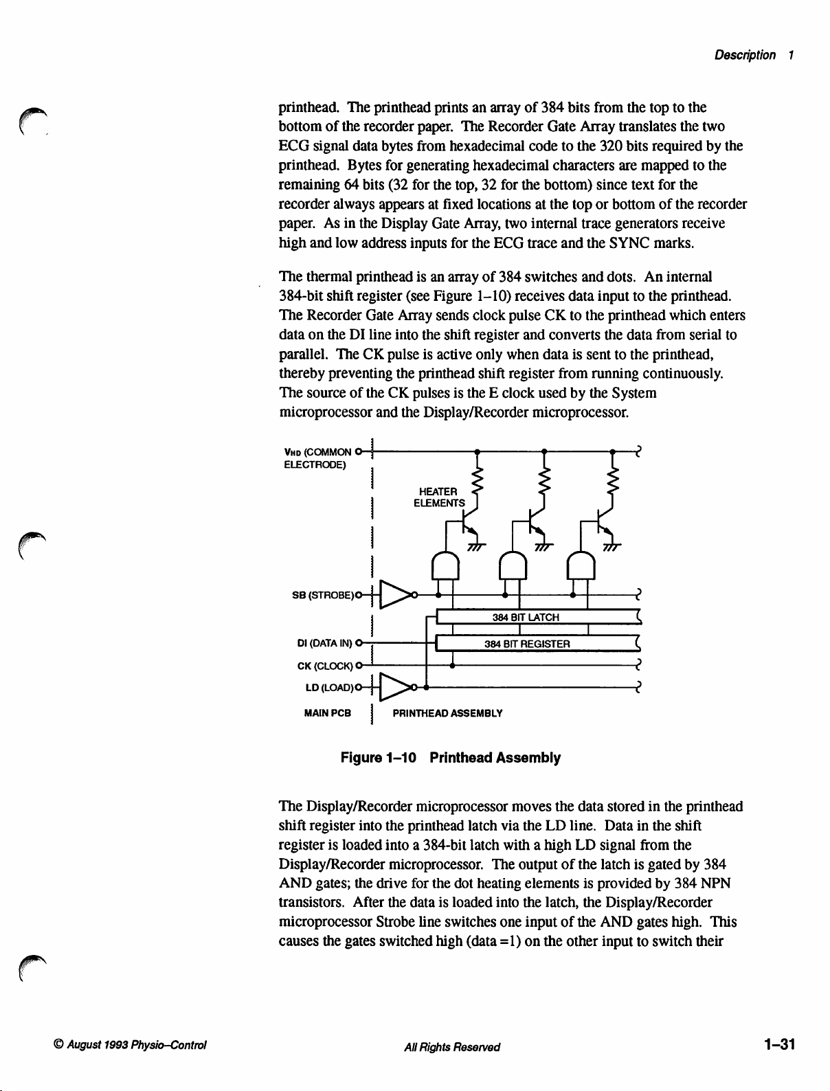
Description
1
printhead.
bottom
ECG
printhead.
remaining
recorder
paper.
high
The
384-bit
The
data
parallel.
thereby
The
The
of
the
signal
data
Bytes
64
always
As
in
and
low
thermal
printhead
shift
register
Recorder
on
the
DI
The
preventing
source
of
recorder
bits
the
address
Gate
CK
the
microprocessor
Уно
(СОММОМ
©
ELECTRODE)
printhead
paper.
bytes
from
for
generating
(32
for
appears
Display
inputs
is
(see
Array
line
into
the
pulse
is
the
printhead
CK
pulses
and
the
|
HEATER
|
ELEMENTS
prints
an
array
of
The
Recorder
hexadecimal
code
hexadecimal
the
top,
32
for
the
at
fixed
locations
Gate
Array,
for
an
array
Figure
sends
shift
active
is
two
the
ECG
trace
of
384
switches
1-10)
receives
clock
pulse
register
only
shift
and
when
register
the E clock
Display/Recorder
1
384
bits
from
the
Gate
Array
translates
to
the
320
bits
characters
bottom)
at
the
top
internal
and
data
CK
to
converts
data
is
from
used
by
since
or
bottom
trace
generators
the
SYNC
and
dots.
input
the
printhead
the
sent
to
running
the
System
are
data
microprocessor.
>
»
top
to
the
the
two
required
mapped
text
for
of
to
the
the
recorder
receive
marks.
An
internal
to
the
printhead.
which
from
serial
the
printhead,
continuously.
し
の
by
the
the
enters
to
SB
(srrosejo-H[
|
DI
(DATA
CK
(CLOCK)
LD
MAIN
IN) © [
©
tonjo-H
PCB
|
Figure
The
Display/Recorder
shift
register
register
is
loaded
into
Display/Recorder
AND
gates;
the
drive
transistors.
microprocessor
causes
the
After
gates
Strobe
switched
229
$ $
+
| |
|
i
22ο
PRINTHEAD
1-10
ASSEMBLY
Printhead
microprocessor
the
printhead
into a 384-bit
latch
latch
microprocessor.
for
the
dot
heating
the
data
is
loaded
line
switches
high
(data
384
BIT
LATCH
384
BIT
REGISTER
Assembly
moves
via
the
with a high
The
output
elements
into
the
one
input
=1)
on
$
the
data
LD
line.
LD
of
the
latch,
of
the
the
other
|
ς
(
2
ο
о
stored
Data
signal
latch
is
provided
the
Display/Recorder
AND
input
in
in
the
from
is
gated
by
gates
to
switch
the
printhead
shift
the
by
384
384
NPN
high.
This
their
©
August
1993
Physio-Control
All
Rights
Reserved
1-31
Page 46

LIFEPAK 9 defibrillator/monitor
outputs
their
Printhead
circuit
When
microprocessor
The
and
printhead.
are
(see
is
printhead.
battery voltage,
printhead
Monitoring
dots
turned
Comparator
sense
monitored
printhead
across
directs
the
microprocessor
dots
high.
respective
Resistance
is
active
the
motor
measured
voltage
The
energized;
Figure
too
long,
The
strobe
turned
on
increases,
resistor
at
increases,
R16
drops
the
Display/Recorder
Recorder
turned
The
heating
only
printhead
during
printhead
this
1-10).
the
excessive
System
the
current
on
determines
U2A
R27
pin 4 through
Gate
on
and
selected
when
speed
starts
energizing
printing
is
regulated
If
the
and
printhead
width.
the
monitors
and
the
lower
Array
then
determines
passes
transistors
elements
Evaluation.
calibration
resistance
duty
strobe
heat
microprocessor
through
combined
voltage
voltage
than
at
this
and
activating
The
the
instrument
test
the
printhead
used
determines
cycle
is
by
the
width
pulse
on
the
dots
temperature,
the
printhead
the
printhead
resistance
the
load
on
divider
voltage
the
dividers
across
the
voltage
microprocessor
STROBE
the
printhead
information
conduct,
dropping a voltage
Printhead
is
in
motor
runs,
the
Display/Recorder
dots.
together
the
optimum
the
time
period
of
the
is
too
short,
will
greatly
monitors
and
calculates
while
resistance.
of
the
VHD
R13
and
R16.
R10
R16
decreases.
across
R15,
to
input.
resistance
to
the
the
selected
Resistance
speed
with
duty
printhead
the
the
printhead
increasing
As
the
printhead
line
at
and
R15.
U2A
stop
sending
The
Display/Recorder
System
printhead
Evaluation
calibration
printhead
cycle
of
that
the
printhead
strobe
print
will
be
shorten
The
When
the
resistance,
the
optimum
the
the
number
decreases.
pin
5,
through
VBATT
As
the
the
switches
strobe
from
the
microprocessor.
across
dots.
mode.
temperature
the
dots
pulse,
SB
light;
if
it
life
of
the
number
of
line
load
voltage
low.
signals
number
of
dots
current
is
on
the
This
to
of
1-32
Display
PCB/CRT
Assembly
(803706)
The
Display
the
Monitor
information
information
synchronization
PCB/CRT
PCB
and
on
the
Assembly
Assembly.
synchronization
CRT.
signals
All
Rights
The
signals
The
incoming
Frame
Sync
Reserved
(Figure
Monitor
from
signals
and
Raster
1-11)
PCB
is
composed
assembly
the
Main
are
Video
Sync.
of a CRT
processes
PCB
and
1,
Video
©
August
and
video
displays
2,
and
1993
Physio-Control
the
Page 47

Description
1
上 一 一
|
|
|
|
|
|
|
|
|
|
|
|
|
|
|
|
一 一 一 一 一 一 一
FRAME
RASTER 一 一 | __
VIDEO 1 ——&
VIDEO 2 —
Figure
Two
The
pixels
and
m|
FRAME
SWEEP
GENERATOR
RASTER RASTER
SCAN
OSCILLATOR
VIDEO
SIGNAL
AMPLIFIER
려
一 一 一 一 一 一 一 一 一 一 一 一 一 一 一 一 一 一 一
=
2
$
1
>|
1-11
separate
CRT
per
left
raster
line.
to
right
Display
circuits
provide
consists
The
CRT
(see
Figure
PCB/CRT
HORIZONTAL
DEFLECTION
YOKE
GENERATOR
RASTER
VOLTAGE
(FLYBACK)
VIDEO
of
768
screen
Assembly
horizontal
scan
is
scanned
1-12).
è
つ
2
lines
There
and
MONITOR
ASSEMBLY
VERTICAL
DEFLECTION
YOKE
CRT
CATHODE
Block
Diagram
vertical
in
one
complete
by a vertical
is
no
interlacing
PCB
r
G4
CRT
一
3
E
a
beam
frame
raster,
bottom
during
deflection.
with
256
to
top
the
raster
VERTICAL
VERTICAL
HORIZONTAL
RETRACE
RETRACE
SCAN
|
|
—
|
Figure
BM
| |
| |
A
WTA
DEN
VÍ
1
PŮ
1-12
Display
|
|
|
Scanning
i}
기
| |
III
n
|
|
©
August
1993
Physio—Control
All
Rights
Reserved
1-33
Page 48

LIFEPAK 9 defibrillator/monitor
Video
Signal
Amplifier
Frame
Sweep
Generator
This
circuit
controlling
The
input
the
Main
U401C
nominal
available
Brightness
A
deflection
during
a
nominal
To
sweep
components.
frequency
horizontal
and
Horizontal
senses
control
eliminate
the
to
PCB
provide
+40V
by
is
horizontal
60Hz
the
of
rolling.
deflection
both
yoke
receives
video
voltage
to
Video 1 and
at
TTL
voltage
biasing
to
switching
the
for
video
the
adjustable
hybrid
the
width
IC,
U101,
retrace.
synchronizing
CRT
accurately,
The
RC
combination,
hybrids
Horizontal
Linearity,
current
and
linearity.
ringing
(oscillation).
information
the
CRT
Video 2 is
levels.
Q401,
causing
output.
outputs
through
Video
drives
The
Display
signal,
U101
internal
R113,
and
oscillator.
Width,
calibrates
provides
R117
at
the
cathode
supplied
The
Q401
Four
levels
of
U401A,
Gain,
the
frame
Gate
Frame
requires
R105,
R111,
the
feedback
and
Video 1 and
at
the
video
from
the
outputs
of
to
conduct
of
video
U401B,
R402.
yoke
Array
on
Sync,
biasing
R106,
and
Horizontal
controls
CRT
beam
to
U101
C112
form a damping
Video 2 inputs,
output
Display
U401A,
and
intensity
and
U401C.
to
sweep
the
Main
for
this
circuit.
by a number
C102,
sets
Hold,
the
width
linearity.
pin
10
(J902
pin
Gate
Array
U401B,
the
R106,
adjustment
supply
are
CRT
PCB
supplies
of
external
the
controls
R128
to
help
circuit
and
2).
on
a
to
Raster
Scan
Raster
Voltage
Oscillator
Generator
The
Raster
and
the
The
circuit
The
voltage
signal.
Q201,
R217
power-on.
size
Input
input
forward-biases
conducts,
input
Vertical
U201
The
T301
comes
Oscillator
Scan
switching
is
designed
regulator
This
signal
causing
and
capacitor
Resistor
will
be
minimally
overvoltage
voltage
at
which
Raster
as
it
pin
Size,
well
from
inhibits
4.
Voltage
rises
R224,
determines
as
the
circuit.
Oscillator
frequency
around
oscillator
is
sent
Q201
to
conduct
C203
R209
affected
protection
to
18V
Q203
which
the
internal
controls
the
Generator
overall
output
CRT
of
sets
the
sweep
for
the
Raster
voltage
frequency
from
the
Display
and
pass
function
decouples
or
as
by
changes
is
provided
greater,
routes
it
oscillator
the
width
amount
the
of
supplies
bias
voltages.
voltage
regulator
frequency
Voltage
regulator
is
set
Gate
the
signal
an
RC
network,
+15V
in
by
Q201, Q202,
D201
starts
to
the
gate
in
U201
of the
energy
the
input
The
U201
for
Generator
U201.
to
about
Array
to
U201
slowing
supply
the
pulse
delivered
+15V
to
conduct.
of
Q202.
by
from
voltage
applying
voltage
input
signal
pin
10
the
Raster
power
52kHz
on
the
Main
pin
5.
the
so
supply.
and
D201.
This
When
+5V
the
output
to
transformer
for
the
primary
for
in
the
Raster
Generator
supply.
by
the
Raster
PCB
Resistor
current
that
display
If
the
signal
Q202
to
the
stage
T301.
the
circuit
Scan
to
at
of
of
1-34
Rights
All
Reserved
August
O
Physio—Control
1993
Page 49

The
Raster
and
transistors
providing
for
total)
winding
This
the
primary
output
on
voltage
additional
Voltage
Generator
Q501
and
Q502.
current
of
T301.
at
pin
Tl
adds
provides a ground
The
5. A tap
+14V
to
circuit
The
for
Q502.
+15V
at
T501
boost
reference
is
designed
oscillating
The
input
at
around
output
output
T501
pin 6 supplies
the
+24V
to
+40V
for
biasing
transformer
of
U201
drives
of
Q502
sets
the
pin 4 produces
+24V.
The
output
G1, G2,
secondary
at
T501
and
T501
Q501,
voltage
+15V
pin
G4.
Description
(30V
8.
1
Raster
CRT
Bias
Generator
Generator
Vertical
circuit.
deflection
The
Raster
transformer
the
for
The
Raster,
causes
of
precise
resonance
voltage
The
anode
for
+11.6kV
which
Focus,
Raster
Scan
drive
the
CRT.
Display
which
Q204
Q205
values
for
CRT
and
bias
largely
R306,
deflection
Because
circuit
Generator,
signal
controls
while
charging
Bias
grid
of
G1,
for
for
the
of
high
consists
like
Oscillator
T301,
which
for
the
Gate
Array
is
passed
to
conduct,
the
charge
of
these
charging
the
Generator
from
the
up
to
+700V
anode
bias.
determines
adjusts
the
raster
yoke
current
circuit.
is
88mH
on
to
and
of
discrete
the
Raster
The
shared
yoke
the
Main
voltage
providing
and
discharge
capacitors
and
discharging.
capacitors.
supplies
output
for
Master
the
general
focus.
of
bias
Brightness,
is
provided
voltage
components,
Voltage
Raster
with
coil.
PCB
regulator
requirements,
Generator
the
CRT
This
supplies
U201.
additional
of
are
essential
Transformer
half-wave
transformer
of
background
G2
and
rectified
R302,
by
the
Raster
the
forming a resonant
Generator,
Bias
creates
current
C208
for
is
circuit
Generator
the
vertical
the
synchronizing
The
output
for
Q205.
through
maintaining
T301
voltage
T301.
It
G4,
and
adjusts
brightness
provides
between
the
Generator
vertical
driven
from
includes
and
scan
of
U201
The
C212.
the
proper
provides
for
the
up
+8.5kV
brightness
of
the
Circuit.
the
provides
drive
signal,
pin
output
The
high
CRT
to
-150V
and
CRT.
9
©
August
1993
Physio—Control
All
Rights
Reserved
1-35
Page 50

Operation
Introduction
This
instrument.
instrument.
manual.
section
This
provides
not
is
It
clinical
For
section
information
use,
to
refer
intended
includes
about
the
to
an
separate
the
instruct
information
basic
operation
operator
Operating
the
about
of
the
clinical
the
in
Instructions
following:
use
of
the
Controls
Indicators
and
Indicators,
Controls
Panel
Front
e
Controls,
Panel
Rear
©
©
Option
e
e
Clock
LIFEPAK 9 defibrillator/monitor
Figures
Note:
Settings,
Setting
2-1 and
Pushbuttons
displayed
Procedure.
2-2
messages
and
Indicators
including
and
described
are
indicated
are
self-tests
indicated
including
Connectors
and
and
controls
in
the
corresponding
in
sans-serif
power-on
and
indicators
in
BOLD
Paddles
default
CAPITAL
CAPITAL
Area
settings
are
identified
Tables
LETTERS
LETTERS.
2-1 and
and
in
2-2.
O
August
1993
Physio-Control
All
Rights
Reserved
2-1
Page 51

LIFEPAK 9 defibrillator/monitor
Mn
PHYSIO-GONTROL
, 내 타 싸 9
LEAD
SELECT
아시아
바이
sti
~
O
OOO
(
a
E
TEO
ii
ER
emma
WANHILS
?
O®@OOQD
®
2-2
GH
Figure
2-1
Front
All
Panel
Rights
Controls
Reserved
and
Indicators
リリ)
©
August
1993
Physio<Oomtrol
Page 52

Operation
2
fm
PAT
Table
|
Item
21
PADDLES
22
23
24
Control
Recorder
AREA
Patient
STERNUM
APEX
Cable
Paddle
2-1
or
Indicator
Connector
Paddle
Front
Panel
Records
time,
Prints
Records
violation
Connection
Defibrillation
placed
ECG
Defibrillation
and one
Also
Controls
ECG
and
sync
mode
selected
to
electrode
serves
energy
automatically
occurs.
for
6-pin
electrode
left
of
during
electrode
discharge
as
positive
and
annotation
(if
active),
and
for
patient
with
sternum
(patient’s
QUIK-LOOK
with
pushbutton,
ECG
Indicators
(cont.)
Function
in
delay
ECG
ECG
lead,
ECG
defibrillation
16
seconds
cable.
one
discharge
QUIK-CHARGE
usually
electrode
mode
whenever a heart
right).
Also
paddle
placed
during
mode
only.
Prints
gain,
and
heart
during
defibrillation.
rate
pushbutton,
serves
usually
as
monitoring.
control
near
(CHARGE)
cardiac
QUIK-LOOK
date,
rate.
alarm
negative
apex.
paddle
monitoring.
25
CHARGE
Momentary
pushbutton
to
charge
defibrillator
from
APEX
paddle.
(QUIK-CHARGE
control)
26
27
28
Charge
Indicator
Discharge
Test
Load
Pushbuttons
(not
shown)
LED
flashes
reached
selected
Pushbuttons
pressed
WILL
FULLY
50Q
storage
simultaneously
NOT
CHARGED
defibrillator
area)
paddles.
during
level.
to
discharge
BE
DELIVERED
test
for
receiving
charge
and
energy.
to
deliver
TO
SELECTED
load.
Metal
defibrillation
glows
Both
energy
UNLESS
contacts
steadily
when
pushbuttons
to
the
paddles.
THE
INSTRUMENT
LEVEL.
(not
shown,
discharge
energy
must
in
energy
has
be
ENERGY
IS
paddles
from
O
August
1993
Physio-Control
All
Rights
Reserved
2-5
Page 53

LIFEPAK 9 defibrillator/monitor
CAUTION
HAZARD.
REFER SERVICING
SERVICE
ELECTRICAL
DO
NOT
REMOVE
TO
PERSONNEL.
SHOCK
COVER.
QUALIFIED
4A
250
WARNING
REPLACE
CAUTION
BEFORE
SLOW
RISK
FUSES
DISCONNECT
CHANGING
BLOW
OF
AS
FUSES
FIRE
MARKED
FUSES.
POWER
Item
1
2
3
4
5
6
7
8
Table
TIME/DATE
MODE
SET
W
ORSVOLA
1mV CAL
Ground
ECG
OUTPUT
AC
Power
Fuse
Cover
Mains
©
Figure
Connector
Power
2-2
2-2
Rear
Rear
Pushbuttons
Pressing
selects
clock
Pressing
Pressing
ORS
Pressing
Eguipotential
ECG
ECG
AC
Access
Rocker
clip
Panel
Panel
once
minutes,
setting
advances
the
volume.
displays a ImV
out
connector;
SIZE
power
panel
switch
is
installed
Controls,
Controls,
for
setting
selects
hour,
mode.
the
up
or
down
The
last
ground
1V/mV
to
set
gain).
connector.
for
changing
turns
ac
which
Indicators,
Indicators,
Function
the
real-time
the
clock
setting
year,
month,
value
displayed
scroll
pushbutton
setting
tie
line
locks
is
retained
calibration
point.
output
fuses.
power
this
switch
and
and
clock.
mode.
day
in
signal
with
on
(I)
©
Connectors
Connectors
Pressing
fields.
Pressing
the
selected
increases
when
on
the
ECG
gain
or
off
in
the
on
power
(0).
repeatedly
again
clock
or
decreases
is
off.
CRT
and
of 1 (press
On
some
position.
exits
the
set
field.
the
recorder.
models
a
2-6
All
Rights
Reserved
©
August
1993
Physio-Control
Page 54

Operation
2
Option
Test
Menu
Settings
The
LIFEPAK 9 defibrillator/monitor
user
to
initiate
language
all
of
these
allows
access
described
The
Test
the
two
other
Menu,
1.
do
Make
and
2.
Continue
SELECTED
Figure
and
heart
options
to
below.
Menu
menus,
the
following:
sure
hold
LEAD
2-3.
SELECTED
TEST.
self-tests,
the
is
the
the
holding
TEST:
This
change
rate
alarm
limits,
is
gained
Setup
through
Menu
top-level
the
Setup
defibrillator/monitor
SELECT
LEAD
and
SELECT
and a list
information
settings
and
the
or
Info
menu
which
Menu
HR
of
tests
is
the
includes
and
power-on
examine
top-level
Menu.
allows
and
the
Info
power
ALARM,
and
HR
are
displayed
Test
Menu.
software
system
Test
All
menus
access
Menu.
is
off.
Simultaneously
then
press
ALARM
which
allows
defaults
data.
Menu
which
and
options
to
the
To
access
ON.
until
the
as
shown
the
such
as
Access
for
then
are
self-tests
the
and
Test
press
message
in
The
Test
Menu
DISPLAY,
(SETUP).
Procedure
in
Section
following
To
exit
the
scroll
down
INFO
DEFIB
DISPLAY
RECORDER
SETUP
EXIT
Figure
allows
and
RECORDER),
The
self-tests
and
the
Test
3.
The
Info
paragraphs.
Test
Menu
to
EXIT,
then
2-3
access
to
the
are
executed
and
Calibration
Menu
and
and
return
press
Test
the
Info
the
to
HR
Menu
four
self-tests
Menu
as
part
Procedure
Setup
normal
ALARM.
(KEYPAD,
(INFO),
of
and
the
Performance
and
Menu
are
described
operation,
press Ÿ ECG
the
are
described
DEFIB,
Setup
Inspection
in
the
Menu
in
SIZE
detail
to
© August
1993
Physio-Control
All
Rights
Reserved
2-7
Page 55

LIFEPAK 9 defibrillator/monitor
Setup
Menu
The
Setup
settings
alarm
1.
2.
such
volume.
First,
press
After
to
scroll
Menu
Menu
as
access
and
hold
the
Test
down
as
shown
SELECTED
TEST:
SETUP
LANGUAGE:
RECORDER:
NOTCH:
LEADS
LEAD:
HR
LIMITS:
ALARM
allows
the
language,
To
access
the
Test
LEAD
Menu
to
in
NOTCH:
VOL:
you
to
the
Menu
SELECT
appears
SETUP.
Figure
examine
notch
filters,
Setup
Menu,
by
turning
and
as
shown
Then
press
2-4.
DIAG
60HZ
NO
LEAD
150
120
040
060
8
II
and
do
HR
HR
160
090
change
heart
rate
the
following:
power
ALARM
in
Figure
ALARM
various
alarm
off.
Then
while
2-3,
to
operating
limits,
pressing
press Ÿ ECG
display
and
simultaneously
ON.
the
Setup
the
SIZE
The
LANGUAGE:
RECORDER:
NOTCH:
LEADS
LEAD:
HR
ALARM
3.
Press
to
4.
After
Store
selected
5.
To
SELECT.
W
Figure
different
NOTCH:
LIMITS:
VOL:
HR
ALARM
scroll
through
you
choose
the
setting
become
exit
the
To
ECG
SIZE
option
Setup
exit
to
2-4
Setup
settings
ENGLISH,
MONitor
50Hz
—
УЕ$
PADDLES
3
limits
ranges:
1
to 8 (A
to
indicate
to
scroll
the
different
the
desired
and
move
the
power-on
Menu
and
the
Test
scroll
down
Menu
are
FRENCH,
or
or
60Hz
ог
МО
or
can
80bpm
short
the
through
option
option
to
the
default
return
Menu
to
EXIT,
as
follows:
DIAGnostic
LEAD
II
be
configured
to
240bpm
tone
sounds
selected
the
selections.
settings.
setting,
next
selection.
settings.
to
the
Test
and
return
then
press
GERMAN,
from
and
with
volume.)
press
HR
Whatever
Menu,
to
normal
HR
or
SPANISH
the
following
20bpm
Press W ECG
press
to
each
level
ALARM
options
LEAD
operation,
ALARM.
100bpm.
change
SIZE
again
to
are
press
A
2-8
All
Rights
Reserved
©
August
1993
Physio-Control
Page 56

Info
Menu
The
Info
Menu
revision
discharges
Menu,
1.
2.
numbers,
do
the
First,
hold
and
After
scroll
to
Menu
allows
recorded
following:
access
the
as
the
LEAD
Test
down
shown
you
and
to
and
Test
SELECT
Menu
INFO.
to
Figure
in
to
examine
examine
fault
status
Menu.
and
appears
Then
2-5.
and
codes
Turn
HR
as
shown
press
the
manufacturing
clear
the
number
recorded.
power
ALARM
HR
off,
while
in
Figure
ALARM
then
date
and
of
defibrillator
To
access
simultaneously
pressing
2-3,
display
to
ON.
press
the
W
the
EPROM
Info
press
ECG
SIZE
Info
Operation
2
©
BUILT:
SYSTEM
DISPLAY
SELECTED
TEST:
INFO
BUILT:
SYSTEM
DISPLAY
DEFIB
USES:
FAULT
STATUS:
Figure
REV:
REV:
20
REV:
REV:
一
-XXX
0000
RETAIN
00
RETAIN
2-5
Info
Manufacturing
Revision
EPROM;
update
Revision
microprocessor
withany
number
changes
(user
number
EPROM
JUN
91
XXX
Menu
date
(user
for
automatically
cannot
change).
for
EPROM;
update
cannot
system
change).
microprocessor
with
the
display/recorder
changes
(user
automatically
cannot
any
EPROM
change).
©
August
1993
Physio—Control
3.
4.
DEFIB
FAULT
Press
FAULT
USES:
STATUS:
HR
STATUS:,
RETAIN.
To
exit
the
To
exit
the
V
ECG
ALARM
Info
Test
SIZE
Records
may
Retains
codes
RETAIN
to
scroll
press W ECG
Menu
Menu
to
scroll
All
Rights
RETAIN
listed
through
and
return
and
return
down
Reserved
the
number
or
any
coded
in
Section 3 on
or
CLEAR
the
SIZE À to
to
to
to
EXIT,
of
defibrillator
CLEAR
instrument
codes.
selections.
toggle
the
Test
Menu,
normal
then
operation,
press
the
number.
page
HR
discharges;
errors
using
3-40;
For
DEFIB
between
press
LEAD
press
ALARM.
the
user
may
USES:
CLEAR
SELECT.
user
error
or
and
2-9
Page 57

LIFEPAK 9 defibrillator/monitor
Clock
Setting
Procedure
clock
the
set
To
following:
1.
Press
TIME/DATE
mode.
corner
highlighted.
2.
Press
setting.
increases
3.
Press
desired
4.
To
field.
The
of
TIME/DATE
MODE
value.
exit the
which
monitor
the
Each
by
clock
is
MODE
CRT
as
SET
time
the
one
increment.
again
to
Repeat
setting
on
the
the
in
the
to
set
mode,
on
rear
current
Figure
rear
to
the
the
press
displayed
displays
shown
on
pushbutton
advance
this
CRT
the
panel
2-6.
panel
is
pressed,
next
entire
MODE
and recorder,
to
clock
The
to
change
field.
time
again
initiate
the
the
setting
single
the
value
Press
and
date.
after
in
minutes
single
SET
the
do
clock
setting
the
lower
field
minute
of
the
field
to
select
selecting
left
the
is
the
day
CLOCK
SETTING
PADDLES
X1.0
23
AUG
Figure
93
09:20
2-6
Clock
Set
200
JOULES
SELECTED
Display
2-10
All
Rights
Reserved
©
August
1993
Physio-Control
Page 58

mL
Testing
Introduction
This
section
defibrillator/monitor.
describes
Topics
how
to
test,
cover:
calibrate,
and
troubleshoot
the
LIFEPAK
9
Performance
In
spection
Procedure
(PIP)
© © The
©
e
Note:
This
defibrillator/monitor
defibrillator/monitor
The
PIP
Test
(page
Performance
The
Test
and
Calibration
Troubleshooting
Prefixes
PIP—
TCP—
Performance
PIP
Checklist
results.
and
Calibration
3-40)
are
identifies
identifies
Inspection
(page
If
the
defibrillator/monitor
Procedure
for
help
Aids.
used
is
case
in
Inspection
Procedure
to
distinguish
Performance
Test
and
Procedure
performing
does
not
3-18)
may
(page
locating
any
Procedure
(TCP)
testing
Inspection
Calibration
(PIP)
within
need
specifications.
to
be
photocopied
fails
3-20)
failed
(PIP)
steps.
Procedure
Procedure
checks
be
opened
any
and
subassemblies.
whether a LIFEPAK
The
to
perform
and
used
part
of
the
the
Troubleshooting
steps.
steps.
the
to
record
PIP,
refer
PIP.
the
to
the
Aids
9
170008-000
August
O
PIP-Purpose
A
Physio-Control
1993
This
PIP
within
check
checks
specifications.
and
after
whether
Perform
any
repair
All
the
LIFEPAK 9 defibrillator/monitor
the
PIP
or
calibration.
Reserved
Rights
regularly
as a periodic
is
performing
maintenance
3-1
Page 59

LIFEPAK 9 defibrillator/monitor
PIP-Scope
and
Applicability
This
PIP
monitor.
LIFEPAK
for
testing
applies
This
to
all
configurations
PIP
does
not
apply
9P
defibrillator/monitors;
information.
to
the
refer
of
the
LIFEPAK 9 defibrillator/
LIFEPAK
to
9A,
their
respective
LIFEPAK
9B,
service
manuals
or
PIP-Definitions
PIP-Requirements
PIP-Required
Equipment
Equipment
Acronyms
BPM
ECG
PIP
QRS
or
QRS
NSR
p-p
Note:
The
below
Performing
specific
equivalent
Pushbuttons
messages
requirements
along
test
used
in
this
procedure
Complex
are
are
indicated
for
test
with
important
this
PIP
requires
instruments
specifications
Table
3-1
Specifications
are:
Beats
Per
Minute
Electrocardiogram
Performance
Refers
Normal
peak-peak
indicated
in
equipment,
safety
the
equipment
are
recommended,
may
be
used.
PIP
Test
Inspection
to
portions
Sinus
Rhythm
in
CAPITAL
BOLD
workstation,
information,
Equipment
of
the
LETTERS
CAPITAL
listed
other
Procedure
ECG
waveform
and
LETTERS.
and
personnel
in
Table
3-1.
test
equipment
Manufacturer
displayed
are
listed
Although
with
3-2
Defibrillator
Energy
ECG
Leakage
Safety
Meter
simulator
Tester/
Analyzer
*Equivalent
Power
Load
Accuracy:
Defib
Accuracy:
110Vac
230Vac
equipment
Range:
Resistance:
+3%
Waveform
Attenuation:
with
oscilloscope
1%
of
Line
Voltage:
Current
Current
Resistance
Current
Range:
Accuracy:
Accuracy:
Line
Voltage:
Range/Accuracy:
2001A/5%
2000uA/1%
Resistance
is
required
Accuracy:
to
meet
All
Rights
0-400J
500
Amplitude
1000:1
output
selected
0-2000uA
+1%
of
reading
of
reading
the
specifications
Reserved
+1%
(minimum)
rate
+1%
+1%
listed
Bio-Tek
Bio-Tek
Dynatech
equivalent*
Dynatech
equivalent*
in
the
specifications
QED-6
QED-6
Nevada
Nevada
column.
170008-000
©
or
equivalent*
or
equivalent*
232,
or
432
HD,
A
August
1993
or
Physio—Control
Page 60

Testing
3
Patient
Recorder
Metric
recorder
Timer
Caution
PIP-Test
Verification
Equipment
Equipment
Cable
paper
ruler
or
paper
*Equivalent
Table
3-lead,
3-lead,
SOmm
per)
Resolution:
1
second
equipment
is
required
Possible
Physio-Control
may
not print
All
test
equipment
label
affixed
certified
calibration
3-1
PIP
Specifications
AHA
or
IEC
(use
only
Physio-Control
1mm
resolution
to
meet
Equipment
(PN
804700).
legibly.
used
to
its
exterior.
facility.
Test
divisions
the
specifications
Damage.
in
performing
The
Equipment
pa-
listed
in
Be
sure
to
Other
paper
the
PIP
calibration
label
(cont.)
Manufacturer
Physio-Control
Physio-Control
Physio-Control
Aristo
or
equivalent
the
specifications
use
only
may
damage
must
have a current
must
column.
recorder
the
be
issued
PN
9-10418-02
PN
800947-01
PN
804700
paper
from
printhead
calibration
by
a
and
PIP-Workstation
PIP-Personnel
Warning
The
ac
line
power
power
Personnel
of
this
experience:
e
e
e
source.
performing
the
LIFEPAK 9 defibrillator/monitor.
PIP
must
Associate
biomedical
Certificate
biomedical
Equivalent
SHOCK
LIFEPAK 9 defibrillator/monitor
through
in
this
attempt
the
HAZARD.
the
PIP,
to
perform
operation
for
this
this
meet
at
least
of
applied
electronics
of
technical
electronics
biomedical
science
When
defibrillator
this
electrical
of
the
paddles.
this
procedure
LIFEPAK 9 defibrillator/monitor.
workstation
PIP
must
one
of
the
degree
training
electronics
charged
discharges
energy
may
must
be
thoroughly
In
following
with a major
in
electronics
experience.
and
discharged
Unless
unless
discharged
cause
you
be
connected
familiar
addition,
up
injury
are
personnel
levels
with a major
to
360J
or
thoroughly
to a grounded
with
performing
of
education
emphasis
emphasis
during
properly
death.
this
of
electrical
as
Do
familiar
the
operation
or
in
PIP,
the
energy
described
not
with
in
170008-000
©
August
A
1993
Physio-Control
All
Rights
Reserved
3-3
Page 61
LIFEPAK 9 defibrillator/monitor
Warning
PIP-General
PIP-Physical
Instructions
Inspection
POSSIBLE
defibrillator
securely
on
formation
electrode
The
are
input
you
Before
power
e
e
e
e
e
e
e © Press
and
the
left,
APEX
of
surfaces
following
designed
of
30bpm
are
instructed
beginning
cord
from
Inspect
including
Inspect
defibrillation
other
Inspect
Remove
Inspect
debris.
Inspect
cracks,
Open
make
latches
Press
display
uniform
all
paddles
foreign
recorder
all
the
breaks,
the
sure
properly.
the
ON
is
ARCING
into
the
internal
properly
paddle
pits
on
paddle
can
sections
to
be
executed
is
specified
to
change
the
PIP-Physical
the
ac
exterior
fluid
spills,
for
gel,
and
matter
for
dust
or
foreign
external
power
bent
battery
ON
again
blank).
mechanical
door
batteries
pushbutton
and
AND
PADDLE
test
stored
in
the
on
the
right).
electrode
cause
patient
are
the
actual
in
sequential
for
one
it.
power
cord
Then
source.
surfaces
pitted
from
ease
connections
or
are
make
resistance.
for
cracks
and
electrode
integrity
paddles
of
door
matter
and
all
broken
on
the
installed.
and
sure
press
DAMAGE.
load,
make
sure
paddle
test
storage
This
helps
surfaces.
skin
burns
PIP
steps
order.
it
also
Inspection,
signs
of
abuse
dents.
plates,
of
cables
and
and
paddle
operation
inside
recorder.
for
bent,
broken,
cables
and
connector
bottom
Close
confirm
the
all
other
pins,
of
the
the
that
green
LED
pushbuttons
When
discharging
the
standard
area
(STERNUM
prevent
Pitted
or
during
to
For
applies
be
presence
and
accessories
defibrillator/monitor
the
defibrillation.
be
performed.
instance,
to
sure
to
or
other
switches.
wells.
positive
or
or
other
door
and
green
is
off
and
paddles
arcing
damaged
and
paddle
These
if a heart
the
next
test
disconnect
damage,
of
dried
Remove
latching.
corroded
for
make
LED
and
pins,
damage,
signs
of
sure
illuminates.
power
check
them
the
are
paddle
steps
rate
unless
the
ac
gel
or
and
wear.
and
it
is
off
(the
for
3-4
PIP-AC
Power
1.
2.
Connect
Ifthe
that
power
on
the
dash
the
power module
switch,
to
step
Dash
Numbers
803800-09
803800-
803800-28
defibrillator/monitor
number
3.
of the
locking
with
defibrillator/monitor
clip
the
switch
Power
to
is
installed
to
Module
ac
the
803800-300
18
803800-309
803800-314
All
Rights
Reserved
power.
at
the
bottom
power
Clip
is
listed
of
on
(I)
position.
Installed
thru
-312
thru
-316
170008-000
O
below,
the
rear
August
confirm
panel
Then
go
A
1993
Physio—Quntrol
Page 62

Testing
3
^.
|
3.
4.
5.
If
the
dash
number
the
bottom
position.
Press
the
ON
Confirm
Confirm
on,
the
of
ON
to
apply
LED
that © 1989,
that
monitor
LEAD
x1.0
of
the
defibrillator/monitor
the
rear
panel
power
power
to
the
illuminates.
PCC
is
within
10
seconds
displays
power-on
Il
©1989,
PCC
Figure
3-1
Power-On
is
not
listed
switch
defibrillator/monitor
displayed
after
information
to
place
it
in
and
for
at
least 5 seconds.
the
defibrillator/monitor
as
shown
=
JOULES
SELECTED
Display
above,
the
on
confirm
in
Figure
press
(1)
that
is
turned
3-1.
、
ーー
PIP-Battery
PIP-Battery
PIP-Setup
Settings
Charge
Power
Menu
With
defibrillator/monitor
confirm
1.
2.
This
settings
down
of
1.
2.
that
BATT
CHRG
With
defibrillator/monitor
ac
power
is
not
Reconnect
defibrillator/monitor
procedure
the
the
PIP.
To
Simultaneously
press
Continue
SELECTED
Figure
source.
displayed.
the
describes
required
current
access
the
ON.
holding
3-2.
ac
for
settings
Setup
TEST:
This
power
is
displayed
power
Confirm
power
the
press
cord
power.
how
to
rest
of
so
you
Menu,
and
hold
LEAD
SELECT
and a list
information
on
and
that
the
and
access
the
PIP.
can
make
LEAD
of
tests
is
the
ac
power
in
the
lower
on,
disconnect
display
press
ON
the
Setup
Before
restore
the
these
sure
defibrillator/monitor
SELECT
and
HR
ALARM
are
displayed
Test
Menu.
source
left
the
remains
to
turn
Menu
changing
settings
and
corner
power
on
but
off
and
any
at
HR
ALARM,
until
the
as
shown
connected,
of
the
display.
cord
from
BATT
CHRG
select
the
proper
settings,
the
write
completion
power
is
then
message
in
the
off.
170008-000
August
O
A
Physio—Control
1993
Rights
All
Reserved
3-5
Page 63

LIFEPAK 9 defibrillator/monitor
3.
Press Y ECG
SETUP
in
Figure
user
SELECTED
TEST:
INFO
DEFIB
DISPLAY
RECORDER
SETUP
EXIT
and
then
3-3.
settings
SELECTED
TEST:
SETUP
Figure
3-2
SIZE A to
press
HR
Before
so
you
changing
can
Test
scroll
ALARM
restore
them
Menu
through
any
the
to
display
settings,
after
Test
Menu.
the
Setup
write
down
completing
Scroll
Menu
the
the
PIP.
to
as
shown
current
m
_
4.
Press
V
5.
To
LANGUAGE:,
Leave
LANGUAGE:
RECORDER:
NOTCH:
LEADS
LEAD:
HR
LIMITS:
ALARM
Figure
HR
ALARM
ECG
SIZE À to
exit
and
the
Test
NOTCH:
VOL:
3-3
to
scroll
change
LANGUAGE:
RECORDER:
NOTCH:
LEADS
LEAD:
HR
ALARM
store
NOTCH:
LIMITS:
VOL:
the
changes,
then
press
Menu
DIAG
60HZ
NO
LEAD
150 120
040
8
Setup
Menu
through
an
option
press
LEAD
displayed
II
160
060
090
the
selection.
Match
DIAG
Match
NO
LEAD
150 120
040 060
8
HR
SELECT
for
the
available
Select:
local
local
Il
ALARM
next
to
return
test,
to
selections.
requirements
line
scroll
to
the
PIP-Keypad
Press
requirements
160
090
back
Test
to
Menu.
Test.
3-6
All
Rights
Reserved
170008-000
©
August
A
1993
Physio—Control
Page 64

PIP-Keypad
Test
The
Keypad
Figure
step.
Press Y ECG
to
start
Press
the
the
following
3-2)
the
Keypad
front
Test
is
which
panel
order:
initiated
should
from
be
displayed
SIZE A to
Test.
pushbuttons
the
Test
scroll
to
and
then
Menu
from
the
KEYPAD,
the
rear
(as
shown
end
of
the
then press
panel
pushbuttons
in
previous
HR
ALARM
Testing
in
3
Press
Front
LEAD
y ECG
ECGSIZE
y
ENERGY
ENERGY
HR
CHARGE
CODE
RECORD
SYNC
Rear
Y
QRS
QRS
MODE
1mV
SET
the
APEX
Panel:
SELECT
SIZE
ALARM
SUMMARY
Panel:
VOL
VOL
CAL
paddle
A
SELECT
SELECTA
A
CHARGE
pushbutton.
170008-000
©
August
A
1993
Physio—Control
Press
the
APEX
Press
the
STERNUM
sounds.
Simultaneously
beep
sounds.
Confirm
SELECT
in
displays
to
Steps 2 through
To
to
that
to
the
order
KEYPAD:
KEYPAD,
exit
the
EXIT
and
the
return
listed
then
Keypad
press
paddle
paddle
press
both
monitor
to
the
above,
FAULT.
press
7.
Test
HR
ALARM
All
Rights
discharge
discharge
paddle
displays
Test
Menu.
or
if
there
In
this
HR
ALARM
after
completion,
to
resume
Reserved
pushbutton;
pushbutton;
discharge
KEYPAD:
If
is a pushbutton
case,
to
restart
confirm
pushbuttons;
OK,
the
pushbuttons
press W ECG
the
press W ECG
normal
no
beep
confirm
confirm
then
press
are
failure,
SIZE À to
Keypad
Test
SIZE A to
operation.
sounds.
no
beep
LEAD
not
pressed
the
monitor
and
that
a
scroll
repeat
scroll
3-7
Page 65

LIFEPAK 9 defibrillator/monitor
PIP-Lead
Select
PIP-Recorder
Speed/Baseline
Centering
1.
Use
the
patient
cable
defibrillator/monitor.
2.
Press
LEAD
SELECT
all
lead
(1,
1,
III)
configurations.
1.
2.
3.
4.
5.
Confirm
Set
Press
select
RECORD
Measure
trace.
Measure
the
there
the
ECG
RECORD,
STD.
to
the
Confirm
the
baseline
is
paper
simulator
let
Let
the
stop
distance
that
baseline
is
centered
to
connect
Set
the
ECG
repeatedly
in
the
recorder.
for a 60bpm-NSR
the
recorder
recorder
the
between
the
centering
run
recorder.
distance
within
the
ECG
simulator
and
run
for
for
the
maximum
between
of
the
+1mm.
simulator
for a 60
confirm
that
signal
approximately
an
additional
peaks
consecutive
recorded
STD
the
in
LEAD
10
of
to
the
bpm-NSR
signal
Il.
10
seconds,
the
recorded
peaks
trace.
signal.
displays
seconds,
then
is
25
+1mm.
Confirm
in
then
press
ECG
that
PIP-ECG
Display
Confirm
Confirm
that
that
STD
x1.0
Figure
the
flatline
all
messages
3-4
display
are
Display
on
the
clearly
with
Flatline
CRT
appears
visible
as
shown
level
in
DI
200
ECG
Trace
JOULES
SELECTED
and
centered.
Figure
3-4.
All
Rights
Reserved
170008-000
©
August
A
1993
Physio—Control
Page 66

PIP-imV
CAL
In
order
to
recorder
page
must
3-5.
perform
be
set
this
to
DIAG
test
the
LEADS
as
described
NOTCH
in
the
must
be
set
PIP-Setup
Menu
to
NO
and
the
Settings
on
Testing
3
PIP-CRT
Ratio
Gain/Aspect
1.
—
ㆍ
Confirm
(press
Press
once.
as
Select
Set
that
LEAD
RECORD,
Confirm
illustrated
Figure
LEAD
the
ECG
the
STD
lead
SELECT
then
press
that a 10.0
in
Figure
3-5
1mV
II.
simulator
remains
if
necessary
the
+0.5mm
selected
to
1mV
select
CAL
p-p
3-5.
CAL
Pulse
for a 60bpm-NSR
from
the
previous
STD).
pushbutton
calibration
on
pulse
signal.
the
rear
is
printed
PIP
panel
test
out
PIP-Heart
Rate
Adjust V ECG
Press
RECORD.
Confirm
20
With
Set
systole
each
Return
+imm
LEAD
the
ECG
indicator
QRS
Input
the
that
the
p-p.
Il
simulator
complex
Rates
ECG
SIZE A for a 34
signal
amplitude
selected,
set
for
(the
heart-shaped
and
that
(bpm)
ECG
the
the
30
60 60
240
simulator
240
selection
+2mm
printed
Size
to
input
rates
symbol)
displayed
HR
30
+2bpm
+2bpm
+5bpm
to
p-p
ECG
display
on
the
ECG
X1.0.
listed
below.
flashes
HR
corresponds:
60bpm-NSR.
on
paper
the
signal.
is
Confirm
display
that
with
the
170008-000
©
August
A
1993
Physio-Contro!
All
Rights
Reserved
3-9
Page 67

LIFEPAK 9 defibrillator/monitor
PIP-Rate
Alarms/
Alarm-Activated
Record
1.
Press
is
displayed
2.
While
twice
3.
Press
about 2 seconds
4. | Set
5.
6.
7.
8.
the
alarm
16
seconds.
Confirm
Press
Decrease
that
the
approximately
Press
HR
ALARM.
in
150/40
and
confirm
HR
ALARM
ECG
sounds,
that
HR
ALARM
the
alarm
HR
ALARM
Confirm
reverse
remains
simulator
the
the
ECG
sounds,
16
video.
displayed
that
to
display
150/40
150
flashes,
heart
rate
and
confirm
simulator
the
seconds.
and
confirm
that
120/60
rate
and
150/40
displays
to
greater
printed
rate
40
flashes,
the
HR
in
reverse
160/90
in
in
normal
than
and
the
on
that the
to
30bpm.
and
that
the
ALARM
video,
display
reverse
video.
150bpm.
recorder
the
printout
alarm
stops.
Press
the
recorder
alarm
stops.
LED
is
on
and
press
HR
ALARM
consecutively.
video.
runs
is
HR
Confirm
Confirm
for
approximately
151bpm
ALARM.
runs
for
150/40
that
that
the
or
higher.
Confirm
after
PIP-Recorder
Annotation/
Real-Time
PIP-Test
Clock
Load
1.
Set
the
ECG
2.
Set
the
defibrillator/monitor
the
rear
panel
increment
TIME/DATE
3.
Press
and
4.
Confirm
5.
Press
1.
Make
defibrillator/monitor.
2.
Press W ENERGY
2001.
3.
Press
RECORD
time
annotated.
that
RECORD
sure
CHARGE.
to
the
simulator
to
the
MODE
the
paddles
to
display
desired
to
advance
and
confirm
time
is
to
stop
the
are
SELECT A as
60bpm.
to
local
the
clock
value
in
to
the
recorder
accurate
recorder.
stored
time.
(Press
setting;
the
the
to
in
press
displayed
next
field.)
begins
within
the
paddle
+1
necessary
TIME/DATE
TIME/DATE
field,
printing
minute.
storage
to
set
the
then
press
with
area
energy
MODE
SET
the
of
the
level
j
on
to
date
to
3-10
All
Rights
Reserved
170008-000
©
August
A
1993
Physio—Control
Page 68

Testing
3
(©
X
PIP-Sync/Sync
Annotation
4.
After
paddle
Confirm
and
annotates
1.
Press
ECG
2.
Press
marker
wave,
3.
Place
V
ENERGY
4,
Press
Simultaneously
the
energy
5.
Confirm
DELIVERED
the
printed
the
defibrillator
discharge
that
LEAD
simulator
SYNC.
(the
and
the
paddles
CHARGE.
that
pushbuttons
TEST
on
the
SELECT
for a 60bpm-NSR
Confirm
inverted
the
SYNC
SELECT A if
After
press
is
discharged
the
recorder
and
ECG
trace.
reaches
200
JOULES
recorder
to
set
that
triangle)
pushbutton
in
the
paddle
the
and
into
the
sync
full
charge,
to
transfer
DELIVERED
printout.
the
defibrillator/monitor
simultaneously
the
energy
displays
signal.
SYNC
defibrillator
hold
prints
markers
MODE
is
clearly
LED
storage
necessary
both
paddle
the
test
load.
the
message
are
displays
visible
flashes.
area
of
to
set
the
reaches
discharge
SYNC
clearly
visible
on
the
energy
full
press
both
into
the
test
load.
on
the
monitor
to
LEAD
on
the
each
defibrillator.
charge,
pushbuttons
TEST
on
Il.
CRT,
the
displayed
Press
level
to
200J.
200
JOULES
each R wave
Set
the
sync
R
until
on
PIP-Recorder/CRT
Noise
6.
1.
2.
3.
4.
5.
Note:
6.
Confirm
off,
Short
Set
Press
Confirm
Select
least
baseline
Return
off
that
and
no
together
the
ECG
RECORD
that
PADDLES
10
seconds,
noise
The
ECG
approximately
the
the
recorder.
the
SYNC
sync
markers
the
gain
to
to
the
CRT
electrodes.
and
is
less
signal
paddles
RA
and
X4.0.
start
and
then
than
that
10
seconds
to
the
MODE
are
visible.
LL
leads
Select
the
recorder.
recorder
Short
confirm
3mm
is
displayed
paddle
display
of
LEAD
baseline
the
that
p-p.
before
storage
and
the
patient
II.
paddle
the
on
the
being
area.
SYNC
cable.
noise
plates
CRT
and
CRT
printed
Press
pushbutton
is
less
than
together,
the
recorder
is
delayed
by
the
recorder.
RECORD
LED
3mm
wait
to
are
p-p.
at
turn
170008-000
August
O
A
1993
Physio-Control
All
Rights
Reserved
3-11
Page 69

LIFEPAK 9 defibrillator/monitor
PIP-Defib
CHARGE
Disarm
LEDs
Check
and
m
Press W ENERGY
Press
the
CHARGE
SELECT À and
pushbutton.
set
the
energy
level
to
OJ.
PIP-Paddle
Polarity
Confirm
continues
Press Y ENERGY
Press
CHARGE
paddle
Confirm
reached.
Simultaneously
charge.
the
—
.
Set
Press
from
Hold
LL,
is
CHARGE
Confirm
message
the
ECG
LEAD
the
the
STERNUM
visible
that
the
CHARGE
to
display 0 JOULES
SELECT À to
and
confirm
LEDs
that
the
LEDs
press
both
that
the
TEST
200
simulator
SELECT
paddles
paddles
on
the
to
storage
on
the
on
RA)
CRT.
LED
does
not
SELECTED.
set
the
that
both
the
flash
during
remain
paddle discharge
CHARGE
JOULES
the
on
and a tone
LEDs
DELIVERED.
for a 60bpm-NSR
select
PADDLES
area.
ECG
simulator
and
confirm
that a positive-going
light
and
selected
front
panel
charge
output
cycle.
sounds
pushbuttons
are
off
signal.
lead
and
connections
that
the
energy
and
when
to
and
the
remove
CRT
to
200].
the
APEX
full
charge
transfer
recorder
the
prints
paddles
(APEX
QRS
complex
is
the
on
3-12
PIP-Charge
Time
Return
the
paddles
Press W ENERGY
sure
the
paddles
Simultaneously
the
defibrillator
displayed
time
is
less
Press
the
energy
displays
into
on
press
reaches
message
than
paddle
the
test
the
CRT
All
Rights
to
the
paddle
SELECT A to
are
securely
CHARGE
360
10
seconds.
discharge
load.
and
Reserved
stored
full
charge
JOULES
pushbuttons
Confirm
three
storage
set
the
in
the
and
start
(as
indicated
AVAILABLE).
simultaneously
that
TEST
tones
sound.
area.
energy
paddle
the
timer.
USE
level
to
storage
Stop
by
the
tone
Confirm
to
200
JOULES
170008-000
©
August
360].
Make
area.
the
timer
and
that
the
transfer
A
1993
when
the
charge
the
Physio—Control
Page 70

Testing
3
PIP-Discharge
Control
Warning
1.
Press Y ENERGY
SHOCK
cords
described
2.
3.
4.
5.
HAZARD.
away
in
Remove
away
from
or
any
other
After
the
displayed
extended
shaking
that
no
Return
Simultaneously
energy
SELECT A to
Help
from
your
body
the
following
the
paddles
the
paddle
object.
defibrillator
message
and
the
paddles
discharge
the
paddles
is
discharged
360
away
occurs.
press
steps.
from
wells
Press
reaches
JOULES
from
and
to
the
both
into
avoid
injury
and
away
the
paddle
at
least
CHARGE.
full
your
coil
cords
paddle
discharge
the
test
set
the
energy
by
holding
from
any
other
storage
three
charge
AVAILABLE)
body
with a moderate
storage
pushbuttons
load.
area.
feet
(indicated
or
any
area.
level
the
person
and
away
keep
other
and
to
260].
paddles
or
Extend
from
by
the
the
coil
object
motion.
confirm
and
object
the
coil
your
tone
and
cords
while
Confirm
that
coil
as
cords
body
the
the
PIP-Energy
PIP-Charge
Dump
Reduction
1.
Place
2.
Press À ENERGY
3.
Press
4.
After
to
300J.
5.
Confirm
paddles
1.
Leave
SELECT W and
2.
Press
3.
When
energy
should
4.
Confirm
you
start
and
confirm
the
paddles
on
the
energy
SELECT W and
CHARGE.
the
defibrillator/monitor
CHARGE
to
the
the
paddles
CHARGE.
full
charge
level
scroll
that
the
REMOVED
paddle
stored
set
the
is
to
1J
and
to
1J
and
full
charge
timer.
that the
storage
in
energy
reached,
press
press
of
Simultaneously
energy
meter
set
charges
is
displayed
area.
the
paddle
level
start
the
CHARGE
CHARGE
1J
is
reached
is
discharged
electrodes.
the
energy
to
360J,
and
storage
to
360J.
timer
and
(to
perform
within a few
within
press
both
into
level
to
change
tones
area.
immediately
20
discharge
the
the
sound.
Press & ENERGY
this
test
seconds).
seconds
test
load.
360J.
energy
properly,
pushbuttons
Return
change
or
less
level
the
you
after
the
170008-000
©
August
A
1993
Physio-Control
All
Rights
Reserved
Page 71

LIFEPAK 9 defibrillator/monitor
PIP-Delivered
PIP-CODE
Energy
SUMMARY
Report
Connect
confirm
1.
2.
the
that
Energy
2J
Press
Place
to
set
paddles
the
Table
Setting
1J
3]
4]
SJ
6J
77
8J
9]
ON
the
the
to
the
energy meter
delivered
3-2
energy
Delivered
Tolerance | Energy
+0.2]
+0.2J
30.3]
+0.4J
+0.5J
30.6]
+0.7J
+0.8J
+0.9J
twice
to
switch
paddles
defibrillator/monitor
on
the
electrodes.
is
within
Energy
tolerances
Refer
for
Tolerances
Setting
10)
20]
30]
50J
100J
2001
3001
360J
defibrillator/monitor
energy
meter
to
LEAD
electrodes.
power
Press
И.
to
Table
each
energy
Tolerance
+1.0J
2.0]
+2.1J
+3.5]
+7.0J
+14.0]
+21.0J
+25.2]
off
then
LEAD
3-2
and
level.
on.
SELECT
3.
Connect
60
bpm-NSR
4.
Press
SYNC.
5.
Press A ENERGY
6.
Press
CHARGE.
and
displayed
paddle
meter.
7.
Press
RECORD
8.
Press
CODE
9.
Confirm
the
data
the
ECG
signal.
message
discharge
twice
SUMMARY.
that
the
shown
in
simulator
to
the
SELECT W and
When
full
charge
200J
AVAILABLE),
pushbuttons
to
format
Figure
to
switch
and
appearance
3-6.
patient
set
the
is
reached
transfer
the
recorder
cable
and
set
energy
the
of
level
(as
indicated
simultaneously
energy
on,
the
into
then
recorded
for
to
200J.
the
off
quickly.
data
a
by
the
press
energy
is
similar
tone
both
to
3-14
All
Rights
Reserved
170008-000
©
August
A
1993
Physio-Control
Page 72

“DESERT
“GAMCALE
EVENT
RECORD:
:
COMMENTS
Testing
3
À
RESHOCK
AMADA.
Led
ag:
ar
mem
sn.
να
ge
dy
Car
"dnb
ue
D
ere
11
X1.0
O
db
V
LEAD I x
ar
à
O
5.
MM.
DO
«AA
€.
re:
a
IO
II
IA
O
a
D
POSTSHOCK
a
aia
R
I
O
e
OI
LEAD 1 X
OLY
ON
IO
OU
ca a ae
a
IO
OR AR
ыы"
0
IM
170008-000
O
August
A
1993
Physio-Control
Figure
3-6
Example
of
All
CODE
Rights
SUMMARY
Reserved
Printout
3-15
Page 73

LIFEPAK 9 defibrillator/monitor
PIP-Leakage
(
Current
GROUND
CD
Check
AAMI/ANSI
American
CSA
(Canadian
Electrotechnical
Laboratories)
Because
tests,
specific
Analyzer
performing
summarized
50Hz.
connect
on
the
STUD
) €
CD
leakage
(Association
National
544.
of
the
wide
instructions
operator’s
these
in
Table
When
measuring
the
ohmmeter
ac
power
)
current
Standards
in
accordance
Standards
Commission)
variety
are
manual
tests.
The
3-3
for
ground
between
connector
reer
ーー
©)
еж.
with
for
the
Advancement
Institute)
Association)
601-1,
of
Safety
not
for
instructions
maximum
120Vac,
resistance
the
as
shown
o
ES1-1985,
IEC
Analyzers
provided
allowable
60Hz,
rear
in
Figure
the
C22.2,
601-2-4,
in
this
about
and
for
panel
ground
GROUND
following
of
IEC
that
leakage
in
the
3-7.
standards:
Medical
AAMI/ANSI
(International
and
UL
may
be
PIP.
Refer
configuring
current
Table
3-4
leakage
stud
and
N
PIN
Instrumentation/
DF2-1989,
(Underwriters
used
for
these
to
your
Safety
and
is
for
230Vac,
current
the
tests,
ground
pin
OHMMETER
Br
3-16
Warning
DEFIBRILLATOR/MONITOR
Figure
3-7
Test
ELECTRICAL
equipment
these
Connections
tests
could
and
REAR
HAZARD.
how
result
All
Rights
PANEL
for
to
execute
in
Reserved
Ground
Make
these
not
detecting
Resistance
sure
you
are
tests.
Failure
excessive
Measurement
familiar
leakage
to
properly
©
with
current.
170008-000
August
your
test
perform
A
1993
Physio-Omabol
Page 74

Testing
3
Chassis
ECG
NOTE:
Chassis
ECG
NOTE:
Table
Parameter
to
Shorted
Interlead
Interlead
Interlead
Paddles,
Paddles,
1.
All
2.
Test
factored
3.
N/A=Not
4.
Ground
the
Table
Parameter
to
Shorted
interlead
interlead
Interlead
Paddles,
Paddles,
1.
All
2.
Test
3.
N/A=Not
4.
Ground
the
*
i=
3-3
Ground
All
Leads
RA-LA
RA-RL
LA-RL
Shorted
Paired
tests
are
procedure
in.
resistance:
ground
3-4
Ground
All
Leads
RA-LA
RA-RL
LA-RL
Shorted
Paired
tests
are
procedure
resistance:
ground
measured
Maximum
Closed
SOURCE
conducted
limits
based
Applicable.
<0.050Q
pin
on
the
Maximum
Closed
SOURCE
conducted
limits
based
Applicable.
<0.100Q
pin
on
the ac
current.
Leakage
Safety
Ground Ground
<69
<9.0
<9.0
<9.0
<9.0 <9.0
<69
(1A)
Current
Open
SOURCE
<69
<9.0
<9.0
<9.0
<69
for
<69 <69
in
both
on
ac
power
Leakage
Ground
<73
<6.4
<8.5
<8.5
<8.5
<24
<18
in
both
on
power
hot/neutral
AAMI/ANSI
as
measured
connector
Safety
(uA)
hot/neutral
IEC
as
measured
connector
normal
Standards
between
(refer
Current
Open
SOURCE
10<
normal
Standards
with
between
(refer
and
to
for
Ground
i*
<24
<18
<18
<18
<24
<18
and
to
120Vac
Safety
(uA)
reverse
with
the
rear
Figure
3-7).
230Vac
Safety
(uA)
<123
reverse
meter
inaccuracies
the
rear
Figure
3-7).
and
Closed
:
ONE
polarities.
meter
inaccuracies
panel
ground
and
Closed
polarities.
panel
ground
60Hz
Safety
Ground
SINK
(uA)
NE
<19
<19
<19
<19
<69
stud
and
50Hz
Safety
Ground
SINK
(uA)
factored
stud
and
in.
170008-000
August
©
A
Physio—Control
1993
Note:
After
completing
settings
settings
on
required
were
page
noted
3-5).
All
the
by
.
Rights
PIP,
be
the
user
when
you
Reserved
sure
to
restore
during
normal
performed
the
Setup
operation
PIP-Setup
Menu
(these
Menu
option
Settings
3-17
Page 75

LIFEPAK 9 defibrillator/monitor
PIP
Checklist
Performance
Physical
AC
Power
Battery
Charge
Battery
Setup
Menu
Keypad
Lead
Select
Recorder
Inspection
Inspection
Power
Settings
Test
Speed/Baseline
Centering
ECG
Display
ImV
CAL
CRT
Gain/Aspect
Heart
Rate
Rate
Alarms/Alarm-Activated
Ratio
Record
Recorder
Real-Time
Test
Sync/Sync
Recorder/CRT
Defib
LEDs
Paddle
Charge
Annotation/
Load
Disarm
Check
Polarity
Time
Clock
Annotation
Noise
and
CHARGE
Customer:
Dept/Location:
Instrument
Serial
Frequency:
Tech.
Type:
Number:
Name/ID:
Pass
口
О О
О
口
口
O
О
口
口
口
口
O
口
口
口
口
口
口
口
Fail
口
О
口
口
O
О
口
口
口
口
О
口
口
口
口
口
口
口
Comments
User
settings
LANGUAGE:
RECORDER:
NOTCH:
LEADS
LEAD:
HR
ALARM
NOTCH:
LIMITS:
VOLUME:
for
normal
ENG
ENG
MON
50HZ
NO
LEAD
150
040
12345678
operation
FRE
POR
or
DIAG
or
60HZ
or
YES
Il
or
PADDLES
120
060
Date:
Model:
Last
Insp:
(circle
GER
SPA
ITA
SWE
o
or
fill
160
090
blank):
.
3-18
All
Rights
Reserved
170008-000
O
August
A
1993
Physio-Control
Page 76
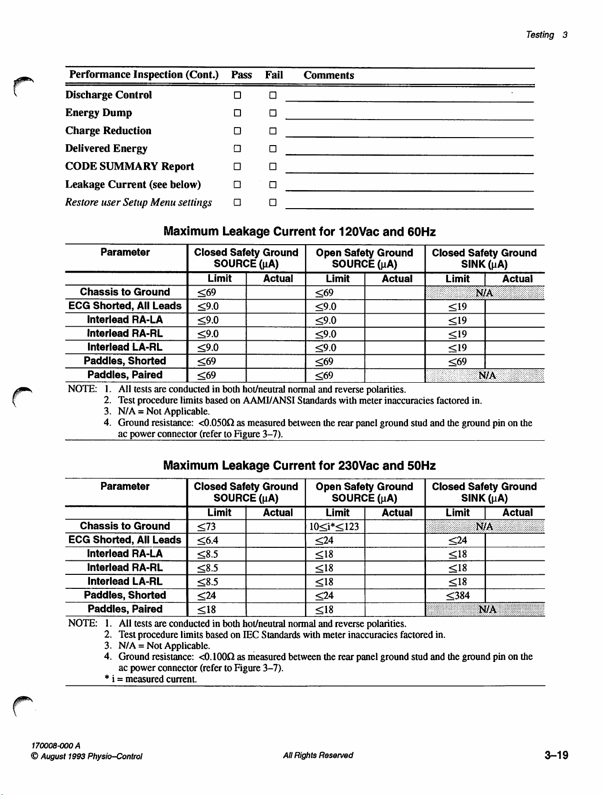
Performance
Inspection
(Cont.)
Pass
Fail
Comments
Testing
3
Discharge
Energy
Charge
Delivered
CODE
Leakage
Restore
ECG
NOTE:
Dump
Reduction
SUMMARY
Current
user
Parameter
Chassis
Shorted,
Interlead
Interlead
Interlead
Paddles,
Paddles,
1.
2.
3.
4.
Control
Energy
Setup
to
Ground
All
RA-LA
RA-RL
LA-RL
Shorted
Paired
All
tests
Test
procedure
N/A=Not
Ground
ac
power
Report
(see
below)
Menu
settings
Maximum
Closed
Limit
<69
Leads | <9.0
<9.0
<9.0
<9.0
<69 <69
<69
are
conducted
limits
based
Applicable.
resistance:
connector
<0.050Q
(refer
0000005065
Leakage
Safety
SOURCE
in
both
hot/neutral
on
as
to
Figure
口
ロロ
ロロ
ロ
口
Current
Ground | Open
(uA)
Actual
normal
AAMI/ANSI
measured
between
3-7).
for
120Vac
SOURCE
Limit
<69
<9.0
<9.0
<9.0
<9.0
<69
and
reverse
Standards
the
with
rear
Safety
polarities.
meter
panel
and
60Hz
Ground
(uA)
|
Actual
inaccuracies
ground
stud
Closed
Limit
factored
and
the
Safety
SINK
|
in.
ground
Ground
(uA)
Actual
pin
on
the
170008-000
O
August
Parameter
Chassis
ECG
Shorted,
Interlead
Interlead
Interlead
Paddles,
Paddles,
NOTE:
A
1993
Physio-Control
to
Shorted
1.
All
2.
Test
3.
N/A = Not
4.
Ground
ac
* 1 =
measured
Maximum
Ground
All
Leads | <64
RA-LA
RA-RL
LA-RL
Paired
tests
are
procedure
resistance:
power
connector
Closed
Limit
<73
<8.5
<8.5
<8.5
<24 <24
<18 <18
conducted
limits
based
Applicable.
<0.100
(refer
current.
Leakage
Safety
SOURCE
in
both
hot/neutral
on
as
to
Figure
Current
Ground | Open
(uA)
Actual
normal
IEC
Standards
measured
between
3-7).
All
for
230Vac
Safety
SOURCE
Limit
10<i*<123
<24
<18 <18
<18
<18
and
reverse
with
meter
inaccuracies
the
rear
Rights
Reserved
and
Ground
(uA)
Actual
polarities.
panel
ground
50Hz
|
factored
stud
Closed
Limit
<24
<18
<18
<384
in.
and
the
Safety
SINK
|
ground
Ground
(uA)
Actual
pin
on
the
3-19
Page 77

Test
Calibration
Procedure
and
TCP-Purpose
(TCP)
The
Test
and
calibration
PIP
(Performance
necessary
is
necessary
tests
These
there
if
or
PIP
completing
Calibration
instructions
Inspection
need
to
be
performed,
to
separate
performed
be
may
suspected
a
is
tests
the
of
any
Procedure
for
the
LIFEPAK 9 defibrillator/monitor.
Procedure),
and
the
case
halves
the
if
failure
this
in
(TCP)
section.
contains
only
these
may
for
some
defibrillator/monitor
assembly.
an
in
those
be
conducted
of
the
in-depth
tests
considered
tests.
fails
Perform
testing
in
any
step
a
the
and
Unlike
order.
PIP
the
the
in
after
It
TCP-Scope
Applicability
and
TCP-Definitions
Note:
This
TCP
apply
to
monitors;
DMM
ECG
ESD
NSR
PIP
p-p
QRS
or
SSD
TCP
If
you
perform
(page
3-1)
afterward
performing
applies
the
LIFEPAK
refer
QRS
within
to
the
to
their
Complex _ Refers
any
of
the
tests
in
this
TCP,
perform
to
confirm
specifications.
that
the
defibrillator/monitor
LIFEPAK 9 defibrillator/monitor.
9A,
LIFEPAK
respective
Digital
Electrocardiogram
Electrical
Normal
Performance
peak-to-peak
Static-Sensitive
Test
9B,
service
Multimeter
Static
Sinus
Inspection
to
portions
and
Calibration
or
LIFEPAK
manuals
Discharge
Rhythm
of
the
Device
Procedure
for
Procedure
ECG
the
This
9P
defibrillator/
testing
waveform
PIP
is
PIP
does
information.
not
3-20
TCP-Requirements
TCP-Equipment
Requirements
The
following
Test
equipment
defibrillator/monitor
is
recommended,
used.
are
minimum
required
is
other
All
Rights
test
requirements:
for
maintenance
listed
in
Table
equipment
Reserved
and
3-5.
with
calibration
Although
equivalent
specific
of
the
LIFEPAK
test
equipment
specifications
may
170008-001
©
August
1993
9
be
Orig
Physio-Control
Page 78

Testing
3
Equipment
Storage
Digital
Function
ECG
Defibrillator
DC
Timer
Components
Freguency
(construction
Figure
Phone
*
Oscilloscope
Multimeter
Generator
Simulator
Energy
Power
Supply
Response
3-14,
plug
Equivalent
(DMM)
for
Recorder
defined
page
3-36)
equipment
Table
Mete
test
in
is
3-5
Test
Specifications
Bandwidth:
Vertical
Horizontal
4-1/2
DC
Low
Output
Amplitude/Freq.
Amplitude/Freq.
Sinewave
Output
r
Power
Load
Accuracy:
Defib
Output
Output
Resolution: 1 second
R1,R2
R3,R4
0.25
required
Accuracy:
Time
digits,
Voltage
Resistance:
Waveform:
Output:
Frequency:
Range:
Resistance:
+3%
Waveform
1000:1
(min.)
Voltage: 0 to
Current: 0 to
Resistor,
Resistor,
inch
plug
to
meet
and
dc
to
2kHz
+5%
Base
Accuracy:
2A
Range
Accuracy:
0.01Q2
Sinusoidal
Accuracy:
Range:
1.0
+0.5mV
10.0
0-400J
5002
Amplitude
with
oscilloscope
20Vdc
3A
100kQ,
100Q,
tip
the
specifications
Calibration
Test
(SmV-5V/division)
+1%
0.1%
of
reading
resolution
on
200Q
+0.5dB/+5%
10V/11MHz
p-p
+0.5Hz
+1%
Attenuation:
output
1/8W,
1%
1/8W,
1%
listed
in
the
specifications
Equipment
Manufacturer
Tektronix
equivalent*
Fluke
equivalent*
scale
Krohn-Hite
equivalent*
Bio-Tek
Bio-Tek
Topward
equivalent*
Aristo
Physio-Control
Physio-Control
column.
Model
Model
8012A
Model
QED-6
QED-6
Model
or
equivalent*
2232
or
or
5400A
or
equivalent*
or
equivalent*
TPS
2000
PN
200054-384
PN
200054-097
or
or
TCP-Test
Equipment
Verification
TCP-Workstation
Requirements
TCP-Personnel
All
test
equipment
calibration
by a certified
Workstations
Discharge
workstation
Personnel
operation
performing
education
label
calibration
where
(ESD)
must
performing
of
the
this
or
experience:
Associate
biomedical
Certificate
biomedical
Equivalent
used
in
affixed
performing
to
its
exterior.
the
TCP
The
calibration
must
facility.
the
TCP
is
protected
be
connected
this
TCP
performed
environment.
to a grounded
must
must
The
be
thoroughly
provide
ac
line
power
LIFEPAK 9 defibrillator/monitor.
TCP
must meet
of
applied
electronics
of
technical
electronics
biomedical
at
least
science
degree
training
electronics
one
of
with a major
in
electronics
experience.
the
have a current
label
must
an
Electrical
power
for
source.
familiar
In
following
with
addition,
levels
emphasis
with a major
be
issued
Static
this
the
personnel
of
in
emphasis
in
170008-001
©
August
Orig
1993
Physio-Control
All
Rights
Reserved
3-21
Page 79
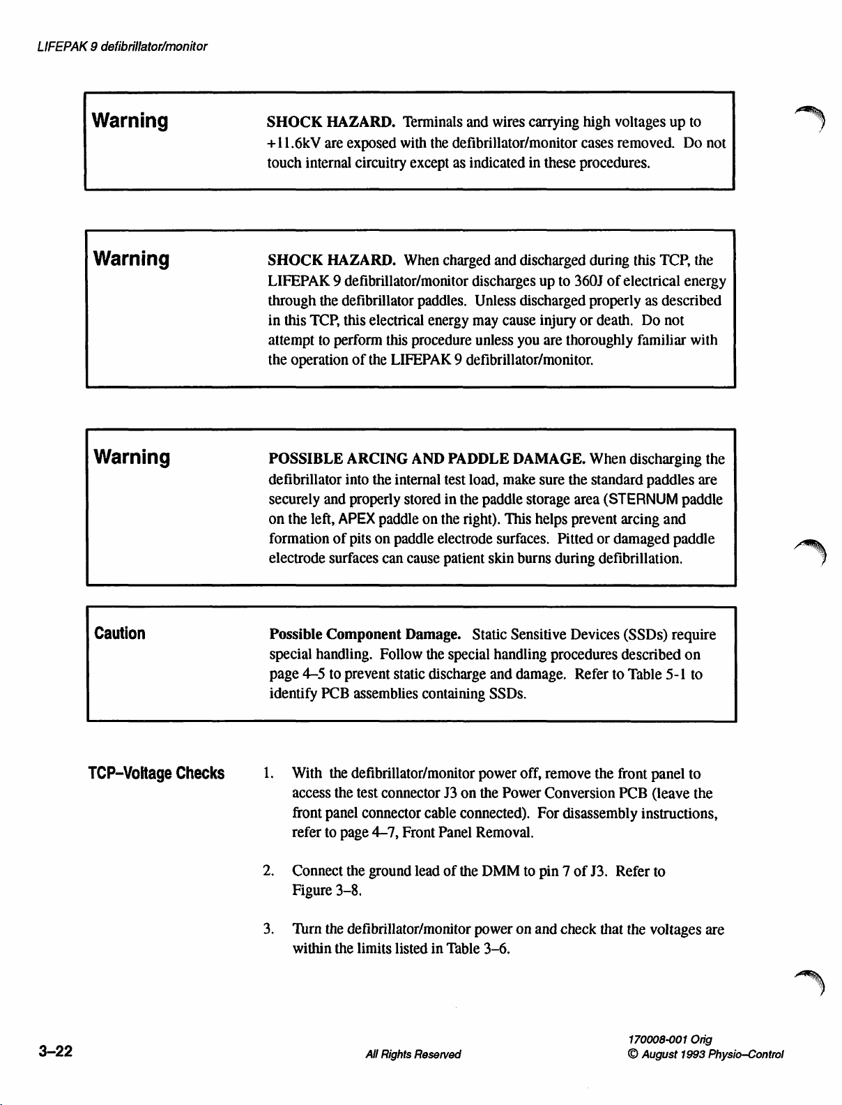
LIFEPAK 9 defibrillator/monitor
Warning
Warning
Warning
SHOCK
+11.6kV
touch
SHOCK
LIFEPAK 9 defibrillator/monitor
through
in
this
attempt
the
POSSIBLE
defibrillator
securely
on
formation
electrode
HAZARD.
are
exposed
internal
HAZARD.
the
defibrillator
TCP,
this
to
perform
operation
ARCING
into
and
properly
the
left,
APEX
of
pits
surfaces
Terminals
with
circuitry
except
When
paddles.
electrical
this
procedure
of
the
LIFEPAK 9 defibrillator/monitor.
AND
the
internal
stored
paddle
on
paddle
can
cause
on
and
wires
the
defibrillator/monitor
as
indicated
charged
energy
PADDLE
test
in
the
electrode
patient
and
discharges
Unless
may
unless
load,
the
paddle
right).
surfaces.
skin
carrying
in
these
discharged
up
to
discharged
cause
injury
you
are
thoroughly
DAMAGE.
make
sure
the
storage
This
helps
prevent
Pitted
burns
during
high
voltages
cases
removed.
procedures.
during
360J
properly
or
When
standard
area
this
of
electrical
as
death.
or
defibrillation.
Do
familiar
discharging
paddles
(STERNUM
arcing
damaged
up
to
Do
not
TCP,
the
energy
described
not
with
the
are
paddle
and
paddle
|
)
Caution
TCP-Voltage
Checks
Possible
special
page
4—5
identify
1.
With
access
front
refer
2.
Connect
Figure
3.
Turn
within
Component
handling.
to
prevent
PCB
assemblies
the
defibrillator/monitor
the
test
panel
connector
to
page
the
3-8.
the
defibrillator/monitor
the
limits
Damage.
Follow
static
connector
4-7,
Front
ground
listed
the
special
discharge
containing
J3
cable
Panel
lead
of
in
Table
Static
Sensitive
handling
and
damage.
SSDs.
power
on
connected).
Removal.
the
power
the
Power
DMM
3-6.
off,
For
to
pin 7 of
on
and
Devices
procedures
Refer
remove
Conversion
the
disassembly
J3.
check
that
(SSDs)
described
to
Table
front
PCB
Refer
the
require
5-1
panel
(leave
instructions,
to
voltages
on
to
to
the
are
3-22
All
Rights
Reserved
170008-001
©
August
Orig
1993
Physio-Control
Page 80

Testing
3
Test
+5V
+5V
Table
Point
Pin
4
Pin
11
Pin
9
Pin
10
Pin
18
Pin
25
HIGH
LOW
LIMIT
3-6
+15V
+5V
+5V
+5V
SW
V
pin
SIGNAL
LIMIT
DETECT
DETECT
Power
Signal
High
Low
BATT
BATT
1
+15V
(4)
GND
(7)
(9)
(10)
+5V
(11)
Figure
Conversion
Name
Limit
Detect
Limit
Detect
TT
———
————>
—»
——
——O
3-8
0
라
A
ΟΟΟΟΟ
«—
¥
000000000
ΟΟΟΟΟΟ
0
(027
Test
Nominal
0
Connector
PCB
Voltage
Voltage
+15.0V
+5.00V
+2.25V
+2.625V
+18.0V
+18.4V
(18)
SW
(25) V BATT
J3
Checks
+0.3V
+0.25V
+0.15V
+0.125V
+2.0V
+1.6V
BATT
Limits
to
-2.4V
to
-2.8V
TCP-Low
Threshold
Monitoring
Battery
Checks
Check
With
1.
access
front
refer
Remove
disconnect
connector
to
Use
Figure
Turn
supply
Slowly
message
supply
seconds
the
the
defibrillator/monitor
the
test
connector
panel
connector
to
page
4-7,
Front
the
battery
the
battery.
inputs.
pin 3 or 4 (red
the
DMM
3-8
the
defibrillator/monitor
output
decrease
LOW
voltage quickly
or
less).
Low
Battery
Connect
wire).
to
monitor
(connect
to
+18.00
the
BATTERY:
Confirm
Limits
J3
cable
Panel
door
on
Connect
the
the
DMM
+0.05
output
enough
listed
power
on
connected).
the
ground
off,
the
Power
Removal.
bottom
the
DC
to
voltage
ground
power
Vdc.
voltage
CONNECT
that
for
to
cause
the
the
on
until
power
remove
Conversion
For
of
power
pin 1 or 2 (black
at
the
to
J3
and
the
AC
the
supply
Monitoring
the
front
disassembly
the
defibrillator/monitor
supply
J3
pin
25
pin
7).
initially
monitor
POWER
message
set
displays
(decrease
to
voltage
Check
panel
PCB
(leave
instructions,
to
the
battery
wire)
and
as
shown
the
appear
in
power
the
the
level
Table
in
within
is
to
the
and
power
power
45
within
3-7.
170008-001
©
August
Orig
1993
Physio-Control
All
Rights
Reserved
3-23
Page 81

LIFEPAK 9 defibrillator/monitor
Defibrillator
Charge
Check
Test
Pin
25
Pin
25
Note:
Point
4.
1.
2.
3.
Table
Function
Monitoring
Defib
Charge
Once
illuminated,
will
not
reset
Return
power
power
for
Use
Figure
Turn
supply
Charge
the
supply
supply
the
Monitoring
the
DMM
3-8
the
defibrillator/monitor
output
the
3-7
Low
Check
Check
the
LOW
until
the
battery
power
supply
voltage
voltage
to
(connect
to
defibrillator
until
is
Check.
monitor
the
+18.00
to
within
DMM
+£0.05
Battery
Low
15.50V
15.00V
BATTERY:
voltage
voltage
the
CRT
the
the
voltage
ground
power
Vdc.
360J.
Thresholds
Battery
+0.23V
+0.22V
CONNECT
rises
to
+18.00
display
Shutdown
at
the
to
on
and
Limits
above
+0.05Vdc.
blanks
Limits
J3
pin
J3
pin
7).
initially
Shutdown
AC
POWER
16.5V.
Slowly
out.
Confirm
shown
25
as
shown
set
the
14.50V
13.50V
+0.21V
+0.20V
message
reduce
that
in
Table
in
power
Limits
the
the
3-7
4.
5.
6.
7.
8.
9.
10.
11.
Gradually
Battery
With
discharge
Repeat
toward
until
Confirm
shown
Return
Charge
Slowly
Limit
Discharge
Repeat
toward
blanks
Limit
the
defibrillator
steps 3 through
the
the
LOW
that
in
the
the
reduce
detection
steps 8 through
the
out.
Shutdown
reduce
the
Table
the
Limits
the
power
detection
paddles
defibrillator
lower
Low
BATTERY:
the
triggering
3-7
for
power
supply
defibrillator
the
power
threshold
defibrillator
lower
Shutdown
Confirm
that
shown
supply
threshold
securely
into
the
$5
above,
Battery
the
Limit
CONNECT
voltage
Defib
voltage
to
360J.
supply
of
+13.70Vdc.
into
10
above,
Limit
the
power
in
Table
voltage
of
+15.22Vdc.
stored
internal
lowering
detection
AC
is
within
Charge
to
+18.00
voltage
the
internal
lowering
of
+13.30Vdc
supply
3-7
for
toward
in
the
test
load
the
power
threshold
POWER
the
Low
Check.
+0.05Vdc.
toward
test
the
power
voltage
the
Defib
the
load
the
paddle
of
the
supply
message
Battery
upper
of
supply
until
the
is
within
Charge
upper
Low
wells,
defibrillator.
voltage
of
+14.78Vdc
is
displayed.
Limits
Shutdown
the
defibrillator.
voltage
CRT
display
the
Check.
3-24
All
Rights
Reserved
170008-001
©
August
Orig
1993
Physio—Control
Page 82

Testing
3
TCP-Test
Access
Menu
Three
of
the
RECORDER)
Menu,
2.
1.
do
Turn
Press
ALARM
SELECTED
TEST:
INFO
DEFIB
the
DISPLAY
RECORDER
SETUP
EXIT
four
tests
on
the
Test
are
used
in
Test
the
following:
defibrillator/monitor
ON
while
until
pressing
the
Test
and
Menu
Menu
and
Calibration
power
holding
is
displayed
(DEFIB,
Procedures.
off.
down
LEAD
as
shown
DISPLAY,
SELECT
in
Figure
and
To
access
and
HR
3-9.
the
Test
Г
o
TCP-Defibrillator
Calibration
Caution
e
Press Y ECG
e
Press
e
Press
Menu.
e
To
exit
HR
ALARM.
1.
With
meter
Possible
level
to
avoid
successive
2.
Access
holding
displayed).
Figure
HR
ALARM
LEAD
the
the
defibrillator/monitor
3-9
SIZE À to
to
SELECT
test
menu,
Test
Menu
scroll
start a test.
to
interrupt a test
press Y ECG
power
electrodes.
Energy
Meter
overheating
order.
the
Test
down
LEAD
Menu
Damage.
the
energy
(turn
SELECT
power
through
SIZE À to
off,
Start
each
meter.
off,
and
HR
the
selections.
in
progress
scroll
place
the
test
at
Test
each
then press
ALARM
until
and
return
to
paddles
the
lowest
energy
ON
while
the
Test
EXIT,
on
energy
level
pressing
Menu
to
the
then
the
in
Test
press
energy
and
is
170008-001
©
August
Orig
1993
Physio—Control
All
Rights
Reserved
3-25
Page 83

LIFEPAK 9 defibrillator/monitor
3.
Press Y ECG
4.
Press
5.
Press Y ENERGY
6.
Press
7.
After
tone,
the
energy
8.
Confirm
XXX,
9.
Read
10.
Press Y ECG
DELIVERED:
11.
Press
SIZE A to
HR
ALARM
CHARGE.
the
defibrillator/monitor
simultaneously
into
that
where
the
value
HR
ALARM
to
SELECTA
the
energy
the
CRT
XXX
is
on
the
SIZE & as
XXX
value
to
start
press
displays
the
energy
energy
enter
scroll
to
the
the
DEFIB
to
scroll
reaches
both
paddle
meter.
the
selected.
meter.
necessary
to
match
the
adjusted
DEFIB
test.
to
LOW.
full
charge
discharge
message
to
change
the
value
value.
test.
Select
as
pushbuttons
JOULES
the
JOULES
on
the
1J..
indicated
DELIVERED:
energy
meter.
by
the
to
transfer
Selected
Value
10
(J)
1
2
3
4
5
6
7
8
9
12.
Table
“Value
0.8
1.8
2.7
3.8
4.8
5.7
6.7
7.6
8.6
9.5
13.
Press
CHARGE.
paddle
meter.
indicated
3-8
Acceptable
discharge
Confirm
Defibrillator
in
Range
After
pushbuttons
that
Table
3-8.
(J) % Tolerance
to
to
to
to
to
to
to
to
to
to
10.5
Press
1.2
2.2
3.3
4.2
5.2
6.3
7.3
8.4
9.4
HR
+20%
+10%
+10%
+5%
+5%
+5%
+5%
+5%
+5%
+5%
ALARM
to
charging
the
energy
is
complete,
to
transfer
meter
Calibration
Selected
Value
20
30
50
100
200
300
360
reinitiate
the
DEFIB
simultaneously
the
energy
value
equals
Measurement
(J)
test.
Acceptable
“Value
19.0
28.5
47.5
95.0
to
190.0
to
285.0
to
342.0
press
both
into
the
energy
the
selected
value
as
Ranges
Range
(J) % Tolerance
to
21.0
to
31.5
to
52.5
105.0
210.0
315.0
to
378.0
+5%
+5%
+5%
+5%
+5%
+5%
+5%
3-26
14.
15.
Repeat
Return
steps 5 through
the
paddles
All
to
Rights
Reserved
13
the
for
each
paddle
energy
storage
level.
area
on
the
defibrillator.
170008-001
©
August
Orig
1993
Physio—Control
x
Page 84

Testing
3
TCP-Test
Load
Calibration
Note:
Complete
calibration
Make
sure
the
defibrillator.
Access
holding
displayed).
Press Y ECG
Press
HR
Press W ENERGY
Press
CHARGE.
After
the
paddle
TCP-Defibrillator
of
the
the
paddles
the
Test
Menu
down
LEAD
SIZE À to
ALARM
defibrillator
discharge
to
pushbuttons
Calibration
test
load.
are
securely
(turn
power
off,
SELECT
start
and
scroll
to
the
DEFIB
HR
the
SELECT A to
reaches
full
charge,
to
transfer
stored
then
ALARM
DEFIB
test.
set
the
the
before
performing
in
the
paddle
press
until
ON
while
the
storage
Test
test.
selected
simultaneously
energy
energy
into
the
this
area
pressing
Menu
to
200].
press
the
test
load.
of
and
is
When
Press
LEAD
Scroll
10.
STD
lead.
Press
11.
12.
13.
CHARGE.
simultaneously
energy
Confirm
Confirm
JOULES
the
CRT
SELECT
to
EXIT
and
into
the
that
the
that
the
DELIVERED.
displays
After
press
test
CRT
recorder
JOULES
to
return
press
the
the
load.
displays
HR
DELIVERED:
to
the
Test
ALARM
defibrillator
paddle
prints
to
discharge
TEST
the
time
Menu.
resume
reaches
pushbuttons
200
JOULES
and
200,
normal
full
date
press
HR
operation.
charge,
to
transfer
DELIVERED.
followed
ALARM.
by
TEST
Select
the
200
170008-001
©
August
Orig
1993
Physio—Control
All
Rights
Reserved
3-27
Page 85

LIFEPAK 9 defibrillator/monitor
TCP-Charge
TCP-Output
Waveform
Time
1.
Make
sure
the
defibrillator.
2.
Press Y ENERGY
3.
Simultaneously
4.
Stop
the
the
time
5.
Simultaneously
energy
1.
Place
the
paddle
polarity
2.
Connect
the
timer
required
into
the
paddles
on
the
right
is
positive.
the
storage
paddles
when
test
are
SELECTA
start
the
the
to
reach
press
both
load.
on
the
electrode
oscilloscope
securely
timer
defibrillator
full
paddle
energy
to
set
and
charge
discharge
meter
of
the
to
stored
the
press
reaches
is
less
electrodes.
energy
the
energy
in
the
paddle
selected
CHARGE.
full
than
pushbuttons
meter
meter
storage
energy
charge.
10
seconds.
to
Place
the
so
that
the
signal
area
to
360].
Confirm
transfer
APEX
pulse
output.
of
that
the
3.
Set
up
pulse
oscilloscope
place
10%
levels.
4.
Press V ENERGY
5.
Press
6.
After
paddle
meter.
7.
Inspect
waveform
Figure
the
oscilloscope
waveform
for
both
the
left
CHARGE.
the
defibrillator
discharge
the
waveform
meets
3-10.
Peak
current
Time
above
Time
above
for
the
capture.
assistance.
and
SELECT
pushbuttons
the
Refer
For
right
measurement
À
reaches
displayed
specifications
=
50%
=
10%
=
“single
to
the
waveform
to
select
full
charge,
to
transfer
on
the
listed
46A
to
2.10ms
3.10ms
shot”
acquisition
Operating
Instructions
parameter
markers
360].
simultaneously
the
energy
oscilloscope
below
and
64A
peak
to
4.20ms
to
9.20ms
mode
measurement,
at
both
the
press
into
the
energy
and
confirm
illustrated
for
for
50%
the
in
the
the
and
that
the
3-28
All
Rights
Reserved
170008-001
©
August
Orig
1993
Physio-Control
Page 86

PEAK
CURRENT - TIME
ABOVE
50%
PEAK
CURRENT - TIME
ABOVE
10%
Testing
3
CURRENT
TCP-Display
Calibration
一 下 一
==
---δ
Tso
The
Assembly
PCB
1.
46A < Ineak
2.10ms < T59 < 4.20ms
following
PCB.
potentiometers.
Disconnect
access
page
to
4-8,
<64A
—>
Figure
paragraphs
Figure
the
ac
the
potentiometers.
Case
Separation.
TIME
3-10
describe
3-11
shows
power
cord.
0.1
Output
the
the
Remove
For
CURRENT
一 十 一
Ipeak
peak
Waveform
calibration
disassembly
ーーーーーー
procedure
location
of
front
and
instructions,
Tio
all
Display
rear
46А < [реак < 64А
3.10ms < Tio < 9.20ms
o!
for
the
—
Display
Assembly
cases
to
allow
refer
to
TIME
Warning
Warning
SHOCK
+11.6kV.
generator
FLYING
vacuum
glasses
2.
Reconnect
Note:
HAZARD.
Do
not
circuitry
GLASS
which
when
Reroute
PCB
may
removing
the
to
prevent
The
contact
when
HAZARD.
implode
ac
input
Ji
ribbon
strain
Display
the
the
the
CRT
cord.
cable
Assembly
CRT
anode
connector
defibrillator/monitor
The
CRT
is
if
broken.
from
underneath
on
Handle
the
Display
Reconnect
the
capacitor
produces
or
power
made
of
glass
with
care
Assembly
J1
on
the
C32
on
the
during
high
the
CRT
is
on.
and
and
front
panel.
Power
the
following
voltages
contains
wear
PCB.
up
bias
a
safety
Conversion
tests.
to
170008-001
©
August
Orig
1993
Physio—Control
All
Rights
Reserved
3-29
Page 87

LIFEPAK 9 defibrillator/monitor
Master
Brightness
(CUTOFF)
Focus
Video
Gain
(VID
GAIN)
Horizontal
(FRAME
Height
HEIGHT)
—
|
TO)
R111
O
ーー
J90
0000000000
G000000000
A306
T301
0
CD
Lineanty
a
δν
vertical
(SCAN
Size
SIZE)
U501
E
©
|
Horizontal
(FRAME
Horizontal
(FRAME
HOLD)
LIN)
Hold
Linearity
J101
~
O
~
NO)
Figure
3-11
Display
PCB
Assembly
Potentiometer
Locations
3-30
All
Rights
Reserved
170008-001
©
August
Orig
1993
Physio—Control
Page 88

Testing
3
Warning
SHOCK
leads
3.
Press
raster
4.
Turn
past
5.
Access
holding
displayed).
6.
Press W ECG
HR
7.
Press W ECG
8.
Adjust:
LIN);
display
HAZARD.
of
R302
ON.
lines
R106,
the
ALARM
and
Adjust
are
Horizontal
point
the
Test
down
R224,
and
R111,
pattern
High
R306.
Use
R302,
visible
where
LEAD
SIZE À to
to
start
SIZE A to
Vertical
behind
the
Menu
(turn
SELECT
the
Horizontal
that
fills
voltages
an
insulated
Master
Hold
horizontal
Brightness
the
(FRAME
power
and
scroll
to
test.
select
the
Size
(SCAN
Height
most
of the
up
to
1000V
screwdriver
characters.
HOLD),
rolling
off,
HR
the
PATTERN
stops.
then press
ALARM
DISPLAY
SIZE);
(FRAME
screen.
may
be
present
for
(CUTOFF),
approximately
ON
while
until
the
test,
then
test.
L201,
Linearity
HEIGHT),
on
the
adjustment.
until
the
vertical
1/8
turn
pressing
Test
Menu
is
press
(SCAN
to
obtain
a
and
a
9,
Loosen
10.
Rotate
11.
Tighten
is
still
12.
Adjust
13.
Adjust
to
make
Note:
14.
Turn
15.
Turn
approximately
DISPLAY:
the
screw
holding
the
yoke
until
the
the
screw
on
the
level.
the
yoke
rings
to
R224
for a display
each
box
of
the
The
adjustments
preceding
R402,
Video
the
defibrillator/monitor
PATTERN
step
until
Gain
minutes.
10
of
the
display
yoke
center
pattern
display
R224
both
(VID
Then,
test.
yoke
clamp.
pattern
clamp
the
pattern
and
measurements
GAIN),
off
is
and
confirm
display
grid
height
approximately
L201]
are
fully
and
allow
access
the
level.
that
the
display
pattern
on
the
CRT.
of
73
+2mm.
interactive.
are
correct.
counterclockwise.
the
CRT
Menu
Test
the
Repeat
to
cool
and
Adjust
same
pattern
height.
the
down
select
L201
for
the
170008-001
©
August
Orig
1993
Physio-Control
All
Rights
Reserved
3-31
Page 89

LIFEPAK 9 defibrillator/monitor
Warning
SHOCK
pins
16.
17.
Note:
18.
Note:
HAZARD.
of
R302
Turn
R302
counterclockwise
Turn
R402
Raster
counterclockwise.
Adjust
Horizontal
the
same
The
above
Potentially
and
R306.
counterclockwise
approximately
clockwise
will
not
reach
R111
for
an
overall
Linearity
width.
adjustments
step
until
both
Use
an
insulated
just
until
the
normal
pattern
(FRAME
of
R111
and
measurements
dangerous
screwdriver
until
the
1/16
turn
normal
LIN)
display
intensity
width
so
R113
are
voltages
raster
more.
if
of
that
are
disappears.
intensity
R302
106
+2mm.
each
box
interactive.
are
correct.
present
for
adjustment.
is
visible.
is
turned
too
Adjust
is
approximately
Repeat
on
the
Turn
far
R113,
the
R302
19.
Adjust
sharpness
20.
Adjust
Confirm
of
difference
2mm.
21.
Turn
the
R402
R402
of
the
yoke
that the
test
pattern
in
clockwise
to
obtain a dim
the
display
rings
difference
is
less
width
from
display.
characters.
to
center
the
in
height
than
or
the
top
until
the
normal
test
from
equal
to
the
Adjust
R306,
pattern
the
to
Imm.
bottom
display
Focus,
on
the
CRT
right
side
to
Check
is
intensity
less
that
than
is
for
maximum
within
the
or
left
the
equal
2mm.
side
to
visible.
3-32
All
Rights
Reserved
170008-001
©
August
Orig
1993
Physio-Control
Page 90

Testing
3
TCP-Power
Calibration
R23
Supply
/
O
7
O
o
—
SIE
[020]
1.
To
gain
rear
Separation).
PCB
Figure
ロロ
ロロ
JP1
mm
access
cases
(for
and
pull
3-12.
J2
ロロ
|
to
R23
disassembly
Then
remove
it
away
ロロ
ロロ
ロ
må
>
2
©
|
on
the
Power
instructions,
the
from
the
four
chassis
Supply
refer
screws
to
access
PCB,
to
holding
page
R23
first
remove
4-8,
the
Power
as
shown
00
L1
Case
RT1
front
Supply
in
and
O
D
ο
C7
ο
0
|
0
LR?
D
o D a
N
R
©
Figure
(re)
3-12
2
©
Q1
Power
Supply
|
|
+
R14
ーー
Calibration
ce
+
CR1
I
170008-001
©
August
Orig
1993
Physio—Control
All
Rights
Reserved
3-33
Page 91

LIFEPAK 9 defibrillator/monitor
2.
Reconnect
the
battery
to
the
defibrillator/monitor.
TCP-Recorder
Calibration
Note:
3.
4.
5.
1.
The
Power
defibrillator/monitor
prior
Supply
to
calibration
stabilizes.
Connect
Connect
Locate
allow
Remove
Main
front
the
DMM
the
ac
power
R23.
Remove
adjustment.
the
front
panel.
PCB)
required
panel
removed
between
Adjust
compensates
must
so
the
the
cord
and
the
potting
R23
The
two
for
Recorder
as
shown
in
for
temperature
be
powered—on
temperature
positive
press
compound
for
+18.40
ON.
around
and
negative
from
+0.18V.
potentiometers
Calibration
Figure
3-13.
fluctuations.
for
at
least
thermistor
battery
R23
as
(R176
are
accessible
30
minutes
RT2
terminals.
required
and
R8
with
on
the
The
to
the
Motor
Paper
Speed
Out
Sense
Figure
Мам
Adjust
РСВ
—
R8
R176
3-13
、
Recorder
Calibration
(FRONT
Adjustments
PANEL
CRT
REMOVED)
Location
3-34
All
Rights
Reserved
170008-001
©
August
Orig
1993
Physio—Control
Page 92

Testing
3
Access
holding
displayed).
Press W ECG
HR
Note:
Turn
Make
Confirm
NO
Slowly
Adjust
NO
repeated
the
Test
Menu
down
LEAD
SIZE A to
ALARM.
During
decreased
Consequently,
R176,
sure
PAPER
PAPER
this
Paper
paper
that the
message
turn
R176
R176
message
to
determine
Make
calibration
to
recorder
just
(turn
SELECT
sure
the
prevent
print
legibility
Out
Sense,
is
installed
is
displayed.
power
scroll
procedure
damage
does
off,
and
HR
to
the
RECORDER:
to
may
on
the
in
the
recorder
not
print,
counterclockwise
to
the
point
where
is
not
displayed.
this
threshold.
then
press
ALARM
RECORDER
PATTERN
the
printhead
the
printhead
range
from
Main
PCB
and
or
if
while
repeatedly
the
recorder
This
procedure
ON
until
light
fully
press
it
does
is
while
the
Test
test,
then
test
is
dot
intensity
and
drive
to
invisible.
clockwise.
RECORD.
print
that
pressing
on
and
the
may
pressing
Menu
is
press
selected.
is
roller.
the
RECORD.
need
to
and
be
Remove
Counting
while
where
make
Adjust
and
Confirm
10.
Press W ECG
11.
Press
12.
printed
Adjust,
turn
Reinstall
13.
the
paper
the
repeatedly
the
recorder
the
adjustment.
R176
to
8.
that
RECORD.
sawtooth
if
necessary
off
the
recorder.
the
from
number
pressing
turns
the
the
recorder
SIZE
Inspect
waveform
front
panel.
the
recorder
of
rotations
RECORD.
on.
midpoint
only
to
select
the
to
obtain
and
required,
Note
the
of
the
number
operates
the
RECORDER:
printout
is
25+1mm.
the
period
close
turn
Adjust
number
when
and
confirm
Adjust
of
25
the
recorder
R176
R176
of
rotations
of
rotations
paper
MOTOR
that
R8,
+1mm.
doors.
counterclockwise
just
to
the
point
required
between
is
loaded.
the
Motor
Press
steps
SPEED
period
Speed
RECORD
to
test.
of
the
6
to
170008-001
©
August
Orig
1993
Physio—Control
All
Rights
Reserved
3-35
Page 93

LIFEPAK 9 defibrillator/monitor
TCP-Recorder
Frequency
Response
1.
Access
holding
displayed).
2.
Press Y ECG
display
LEADS
at
the
end
3.
Press
LEAD
scroll
to
4.
Press
LEAD
V
ECG
5.
Connect
signal
GND
SIGNAL
FUNCTION
GENERATOR
the
Test
down
LEAD
SIZE A to
the
Setup
NOTCH
to
enter
SELECT
EXIT,
then
SELECT
SIZE A as
the
function
setup
shown
R1
100k0Y/1%
R2
100kQ/1%
1000:1
Menu
SELECT
Menu.
is
set
the
press
needed
in
AN
(turn
power
and
scroll
Make
to
NO
(if
option
to
to
generator
ATTENUATOR
return
HR
set
the
to
Figure
changes).
to
ALARM
select
3-14.
off,
then
press
ON
HR
ALARM
to
SETUP,
sure
RECORDER
making
the
Test
to
defibrillator/monitor
X1.0
to
the
patient
R3
1000/1%
until
then
any
changes,
Menu,
resume
gain.
cable
press
is
press Y ECG
normal
input
R4
1000/1%
while
pressing
the
Test
HR
ALARM
set
to
DIAG
press
HR
operation.
to
LEAD
using
PATIENT
CONNECTOR
Menu
to
and
ALARM
SIZE
II.
Press
the
and
is
to
test
3-36
Figure
6.
Note:
7.
3-14
Set
the
function
to
turn
on
Because
signal
for
approximately
appears
Set
the
function
printout
10.5mm
the
input
and
p-p.
All
Test
Signal
generator
recorder.
the
ECG
by
approximately
on
the
printout.
generator
confirm
Rights
Reserved
that
Setup
for a 1V
trace
10
seconds
to
the
for
Function
p-p,
on
the
recorder
10
before a change
0.05Hz.
recorded
10Hz
sinewave.
printout
seconds,
After,
15
trace
is
Generator
lags
the
recorder
to
the
seconds,
between
7mm
170008-001
©
Press
RECORD
behind
must
input
signal
examine
p-p
August
1993
the
run
the
and
Orig
Physio-Control
Page 94

10.
11.
12.
13.
Set
the
function
printout
10.5mm
Set
the
function
printout
10.5mm
Set
the
function
printout
10.Smm
Set
the
function
printout
Access
the
NOTCH
Press
LEAD
scroli
to
and
confirm
p-p.
and
confirm
p-p.
and
confirm
p-p.
and
confirm
Test
to
YES.
SELECT
EXIT,
generator
that
generator
that
generator
that
generator
that
Menu
and
Press
to
then
press
to
0.5Hz.
the
recorded
to
60Hz.
the
recorded
to
100Hz.
the
recorded
to
110Hz.
the
recorded
then
HR
ALARM
return
HR
ALARM
the
to
After
Setup
to
the
After
trace
trace
After
trace
After
trace
Menu.
enter
Test
to
resume
15
seconds,
is
between
15
seconds,
is
between
15
seconds,
is
between
15
seconds,
is
less
the
option
Menu,
examine
9mm
examine
7mm
examine
7mm
examine
than
7mm
Set
the
LEADS
change.
press W ECG
normal
operation.
the
p-p
the
p-p
p-p
p-p.
SIZE
and
and
the
and
the
Testing
to
3
E
14.
Press
output
60Hz).
15
.
Press
that
Access
16.
MON
option
17.
Set
Press
18.
gain
Press
19.
generator
confirm
LEAD
to a 1Vp-p
RECORD.
the
recorded
the
Test
and
set
changes,
the
function
LEAD
to
X1.0.
RECORD.
frequency
the
SELECT
sinewave
After
trace
Menu
LEADS
then
generator
SELECT
Wait
recorded
to
select
15
is
less
and
NOTCH
exit
to
select
10
from
trace
the
seconds,
1Hz
LEAD
Il.
and
match
seconds,
then
for a 1Vp-p,
than
the
to
NO.
Setup
LEAD
examine
Imm
Setup
Menu
Il.
then
to
40Hz.
is
7mm
p-p
Set
the
the
input
the
p-p.
Menu.
Press
HR
and
Test
1Hz
sinewave.
Press W ECG
slowly
Examine
minimum.
function
line
frequency
printout
Set
RECORDER
ALARM
Menu.
SIZE A to
sweep
the
the
printout
generator
(50Hz
and
confirm
to
enter
the
function
and
to
set
or
the
170008-001
O
August
Orig
1993
Physio—Control
All
Rights
Reserved
3-37
Page 95

LIFEPAK 9 defibrillator/monitor
TCP-CRT
Response
TCP-ECG
(when
applicable)
Frequency
Output
Press W ECG
Connect
divider
Set
Decrease
the
Increase
the
Disconnect
Press
Connect
divider
Set
the
the
(as
the
function
the
trace
displayed
the
trace
displayed
LEAD
the
(as
the
function
1000:1
function
illustrated
function
the
SELECT
function
illustrated
divider.
SIZE A to
generator
in
generator
function
generator
on
the
generator
on
the
function
to
generator
in
generator
increase
Figure
the
to
the
3-14
for a 1Vp-p,
signal
CRT
15
19
signal
CRT
is
19
generator.
select
LEAD
to
the
Figure
3-14
for a 1Vp-p,
ECG
gain
patient
on
page
10Hz
frequency
+2тм
+2mm
р-р.
frequency
p-p.
Il.
patient
on
page
10Hz
to
X1.4.
cable
through
3-36).
sinewave.
to
1Hz.
to
40Hz.
cable
through
3-36).
sinewave
at
the
1000:
Confirm
Confirm
the
1000:
the
output
1
that
that
1
of
Connect a 0.25-inch
the
defibrillator/monitor.
Press W ECG
Confirm
that
the
phone
SIZE A to
oscilloscope
plug
to
the
Connect
set
the
the
gain
displays a 1.00
ECG
output
oscilloscope
to
X1.0.
on
to
+0.15Vp-p
the
rear
the
phone
sinewave.
panel
plug.
of
All
Rights
Reserved
170008-001
©
August
Orig
1993
Physio—Control
Page 96

Testing
3
TCP
Voltage
Low
Test
Checklist
and
Calibration
Checks
Battery
Monitoring
Defib
Charge
Test
Menu
Access
Defibrillator
Selected
Value
(4)
1
2
3
4
5
6
7
8
9
10
Threshold
Checks
Check
Check
Calibration
Acceptable
value
(4) % Tolerance
0.8
to
1.2
1.8
to
2.2
2.7
to
3.3
3.8
to
4.2
4.8
to
5.2
5.7
to
6.3
6.7
to
7.3
7.6
to
8.4
8.6
to
9.4
9.5
to
10.5
Customer:
Dept/Location:
Instrument
Serial
Frequency:
Tech.
Type:
Number:
Name/ID:
Pass
口
口
口
口
Range
MEASURED | Selected
VALUE 人 |
+20%
+10%
+10%
+5%
+5%
+5%
+5%
+5%
+5%
+5%
Fail
口
口
口
O
Comments
Value
20
30
50
100
200
300
360
(5)
Acceptable
Value
19.0
28.5
47.5
95.0
to
190.0
to
285.0
to
342.0
to
(4)
to
21.0
to
31.5
to
52.5
105.0
210.0
315.0
378.0
Date:
Model:
Last
Insp:
Range
%Tolerance
15%
+5%
+5%
+5%
+5%
+5%
+5%
MEASURED
VALUE
(J)
Test
Charge
Output
Display
Power
Recorder
Recorder
CRT
ECG
170008-001
©
August
Load
Calibration
Time
Waveform
Calibration
Supply
Calibration
Frequency
Frequency
Output
Orig
1993
Physio-Control
Calibration
Response
Response
口
口
口
O O
口
О
口
口
口
口
口
口
口
口
口
口
口
All
Rights
Reserved
3-39
Page 97

Troubleshooting
Aids
Error
Codes
SERVICE
and
Indicator
The
information
software
an
Physio-Control
outside
The
or
instrument
the
LIFEPAK 9 defibrillator/monitor
When a software
SERVICE
code
is
generated
To
access
holding
displayed.
HR
FAULT
with
To
RETAIN
than
in
displays
Test
HR
down
ALARM
STATUS.
each
remove
(or
one
error
sequence.
00),
Menu.
ALARM
in
this
circuit
problems.
problem
customer
US,
contact
or
circuit
message
is
and
the
Info
Menu,
LEAD
Press W ECG
to
display
Refer
error
code.
or
“clear”
CLEAR),
code
has
After
all
press
LEAD
Press W ECG
to
resume
section
cannot
service
the
local
problem
displayed
displayed
turn
SELECT
SIZE
the
Info
to
Table
an
error
then press
been
error
codes
SELECT
SIZE
normal
may
help a service
It
consists
be
isolated
of
specialist
Physio-Control
contains
is
detected
on
the
monitor.
in
the
Info
power
off,
and
HR
ALARM
to
scroll
down
Menu.
code,
generated,
3-9
ECG
are
to
to
scroll
press
The
for
SIZE & to
the
cleared
exit
down
operation.
technician
the
self-diagnostic
and repaired,
in
the
US
at
representative.
self-diagnostic
during
For
many
Menu.
then
press
ON
until
the
to
INFO,
error
code
the
software
HR
ALARM
CLEAR
next
error
(and
the
the
Info
Menu
to
EXIT,
isolate
error
codes.
contact
1-800-442-1142;
operation,
while
Test
then
number
or
to
code
FAULT
a
software.
problems,
pressing
Menu
press
is
circuit
scroll
down
the
error.
will be
STATUS
and
return
then
press
the
is
listed
associated
If
displayed
to
Testing
possible
If
an
error
and
beside
to
more
the
3
After
the
error
code
display.
SERVICE
representative
Error
If,
however, a software
message
for
Code
μα
N
LU
a
ひい Uu
EW
=
o
is
cleared,
is
again
displayed.
assistance.
Table
Watchdog
Watchdog
3-9
Unknown
Unknown
Recorder
Shock
System
System
System
Critical
motor
Advisory
RAM
microprocessor
controller
ROM
the
SERVICE
or
circuit
Error
Software
hardware
hardware
transfer
watchdog
code
stalled/paper
Adapter
test
ROM
(U27)
message
problem
is
still
exists
removed
or
reoccurs,
Contact a Physio-Control
Codes
or
Circuit
(fast
test)
(slow
test)
code
jam
(U28)
RAM
(U30)
(U27)
from
the
the
3-40
All
Rights
Reserved
©
August
1993
Physio-Control
Page 98

Testing
and
Troubleshooting
3
Error
Code
11
12
13
14
15
16
17
18
19
20
21
22
23
24
Table
3-9
Display
Error
interface
Display/recorder
Display
D/A
Transfer
Transfer
Charge
Preamp
interface
converter
switching
enable
reference
baseline
Clock
+SV
supply
+15V
Defib
A/D
converter
Recorder
out
supply
cal
factors
printhead
Codes
Software
RAM
microprocessor
ROM
CRC
stuck
out
out
of
out
of
out
(U9)
or
(U13)
(U14)
(Q4,CR4)
on
of
tolerance
of
tolerance
tolerance
tolerance
of
tolerance
self-test
resistance
(cont.)
Circuit
RAM
out
of
tolerance
(U1)
©
August
1993
Physio-Control
All
Rights
Reserved
Page 99

Introduction
This
e
section
Battery
provides
Maintenance
the
following
information:
Battery
Maintenance
Warning
e © General
©
©
Special
©
Disassembly
e
Inspection
©
Tools
e
Cleaning
e — Printed
e
Preparation
The
Battery
interim
of
power
power
ac
power.
if
the
POSSIBLE
battery
may
battery
LOW
display,
power,
cause
warning.
BATTERY:
Maintenance
Handling
Procedures
Techniques
and
Materials
Procedures
Circuit
Pack
power
the
immediately
Board
for
Storage
in
the
while
transporting
The
defibrillator/monitor
cord
DEFIBRILLATOR
the
large
defibrillator
If
the
CONNECT
Procedures
for
Repair
LIFEPAK 9 defibrillator/monitor
is
disconnected
current
defibrillator
connect
for
Cleaning
Precautions
or
Shipping.
patients
SHUTDOWN.
draw
to
reach
AC
POWER
the
power
Static
Sensitive
and
Repair
or
during
automatically
or
the
ac
required
shutdown
shuts
down
message
cord
to
for
voltage
Devices
provides
other
brief
switches
power
source
When
operating
defibrillator
levels
without
an
warning,
appears
ac
power
short-term
interruptions
to
battery
fails.
on
charging
with
no
low
or
if
on
the
monitor
source.
the
©
August
Recharging
1993
Physio-Control
Batteries
The
defibrillator/monitor
whenever
front
switch
the
panel
must
instrument
power
switched
be on).
The
All
Rights
continually
is
connected
off
BATT
charges
to
(although
CHRG
message
Reserved
an
the
the
installed
ac
power
rear
panel
appears
Battery
source,
ac
mains
on
the
even
lower
Pack
with
power
left
the
4-1
Page 100

LIFEPAK
defibrillator/monitor
9
Battery
Maintenance
Guidelines
monitor
the
corner
Battery
in
of
is
Pack
hours.
24
trickle-charge
a
Battery
The
maintained
Battery
Whenever
e
connected
This
on
When
e
the
power
operation
Battery
life.
the
e
Perform
Pack a minimum
Battery
e
Replace
minimum
After
Pack
to
Packs,
charges
the
monitor
the
monitor
source
Pack
the
If
Battery
Pack
display
recharged
charging,
full
maintains
which
contains
maximize
follow
LOW
and
the
the
these
power
ac
power
ac
to
Battery
the
display.
BATTERY:
display,
(with
begin
when
battery
low
needs
Pack
Battery
may
Battery
of
every
of
during
capacity
90%
to
the
the
lead-acid
sealed
battery
life
guidelines:
available,
is
the
(with
Pack
CONNECT
immediately
panel
rear
the
recharging
minimum
at
is
it
message
be
to
Capacity
every
six
not
be
functioning
Pack
installed
two
years.
fully
battery
in
charging.
three
A
hours,
defibrillator/monitor
Battery
the
charge
and
as
the
replaced.
Check
months
on
batteries
performance.
defibrillator/monitor
the
keep
mains
panel
rear
indicated
connect
mains
Battery
occurs
in
by
POWER
AC
the
power
Pack.
reserve
frequently,
(p.
4-2)
or
whenever
properly.
the
defibrillator/monitor
which
To
power
BATT
the
power
ac
switch
Frequent
capacity
this
on
the
installed
you
depleted
full
to
and
be
maintain
switch
appears
to
continue
to
use
reduce
indicate
to
properly
an
continues
Pack.
must
properly
CHRG
message
cord
on)
will
may
Battery
suspect
a
capacity
supply
on).
message
on
ac
the
of
battery
that
the
Guidelines
for
Replacement
Battery
Capacity
Check
Batteries
End
of
battery
diminish.
replaced a minimum
To
maximize
these
guidelines:
e
Perform
a
minimum
Check,
returning
e
Recharge
before
e
Store
To
check
procedure
range
of
1.
Install
the
charged,
life
The
Battery
the
life
the
Battery
of
be
sure
it
to
any
storing
replacement
the
capacity
requires
0-400)):
the
Battery
Battery
Pack
go on
is
inevitable.
Pack
installed
of
every
two
and
performance
Capacity
every
six
months.
to
recharge
storage.)
new
replacement
it
or
using
it.
Battery
of a Battery
the
use
of a Defibrillator
Pack
in a LIFEPAK 9 defibrillator/monitor
for
at
least
to
the
next
As
batteries
in
years
Check
(If
the
Battery
Battery
Packs
at
Pack,
24
hours
step).
age,
their
charge
the
defibrillator/monitor
as a preventive
of
replacement
on
any
replacement
it
passes
Pack
for
Pack
20°
to
25°C
perform
Energy
(if
the
Battery
maintenance
Battery
the
Battery
24
hours
as
soon
(68°
the
following
Meter
as
to
with a power
Pack
capacities
should
practice.
Packs,
Battery
Capacity
before
you
77°F).
is
follow
receive
steps
(this
and
already
Pack
charge
be
at
it
fully
4-2
All
Rights
Reserved
©
August
1993
Physio-Control
 Loading...