

Page 1
Title: Defibrillator – Lifepak 9 Date: March 12, 2020
By: Physio-Control
File = Lifepak9Rev 1.0
DISCLAIMER: THIS PROCEDURE PROVIDED "AS IS" AND WITH
POSSIBLE FAULTS. USER MUST VERIFY BEFORE USE.
NEITHER PROVIDER NOR WEBSITE ASSUMES ANY
RESPONSIBILITY FOR ITS USE.
1. General
Applies to Physio-Control Model Lifepak 9 (1994)
2. Reference Documents
Lifepak 9A Defibrillator / Monitor Operating Instructions
P/n 805383-003 or 805455-003; Paddle Use Manual
Service Manual P/N 803763-05 or 805378-01.
@ frankshospitalworkshop.com
3. Accessories / Tools / Fixtures
Chart Paper: 50mm x 100m = Physio-Control P/N 804700 or
Philips 40457C/D
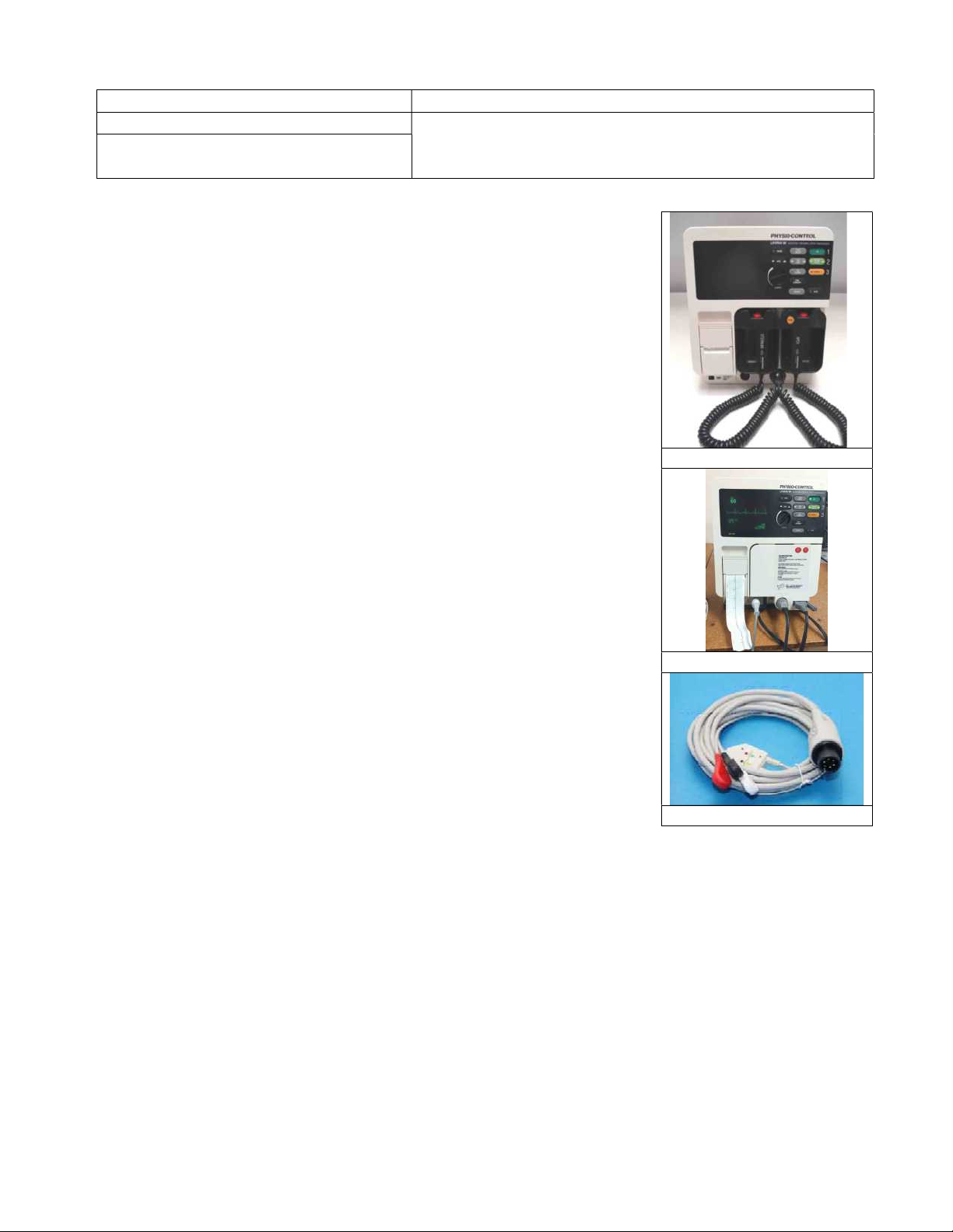
Three lead, 6 prong ECG cable
EKG Simulator ex: Biotek ECG-1
Defib Output Analyzer
Electrical Safety Analyzer
This procedure first checks the unit with line power; often the only repair issue
is battery quality/replacement. See Appendix. For other reference, see Section 6
of Operating Instructions for a more extensive maintenance procedure.
4. Basic PM Procedure
4.1. Physical Inspection. Check unit for cracks, ECG lead, power cord
and paddle leads for abrasions etc. Check that paddles are clean and
easily removed and re-installed. To clean, per manual, “do not use
alcohol, solvents, or cleaning solutions.”
4.2. Line Power Check
After plugging in the unit but before turning on, note that the
“BATTERY CHRG” is lit. Turn unit on. The CRT monitor should
show a trace in a few seconds. Note if the “Service” indicator lights,
the cause can be poor batteries.
4.3. ECG Setup and Connection
Adjust your ECG simulator for 60-100 BPM and an output between 1 and 2 millivolts. Connect the
unit’s three ECG leads to the defib simulator, matching the colors or other designators.
4.4. ECG Display and Recorder.
If an ECG waveform does not appear on the monitor screen, press <LEAD SELECT> until
waveform appears. Verify that that <ECG SIZE> and QRS volume -- QRS adjusts on rear of unit.
Compare displayed heart rate to the simulator’s setting. Start and stop the thermal printer by hitting
<RECORD> and check the trace/waveform. See Appendix for recorder print example.
4.5. Defibrillator Joule Check (three methods)
With Paddles
With Adapter
ECG Cable
Page 2
The No Analyzer Method - No Paddles Needed: With the “QUIK-COMBO PACING
DEFIBRILLATION ADAPTER” in place, connect the power cable as shown in the above photo.
Set <Energy Select> to 200 joules. Press <CHARGE> and after screen shows charging done, press
both of the red shock buttons simultaneously. This works only at 200. If succesful, screen will
display “200 joules delivered.”
The No Analyzer Method – Using Paddles With the paddles in place in their holders, set
<Energy Select> to 200 joules. Press <CHARGE> and after screen shows charging done, press
both of the red paddle shock buttons simultaneously. This works only at 200.
Joule Test Using Paddles and External Analyzer.
Be sure the paddle cable connector is fully locked onto the main unit. Set the “Energy Select” for
50 joules, and use the paddle’s charge button to start the shock. In less than 10 seconds the unit
will announce it’s ready with an audible tone. With paddles on the joule tester, hit both the red
paddle shock buttons simultaneously and check that the delivered joules match “Energy Select” to
within ____ tbd. The internal power oscillator may make a faint buzz while charging. Using a
higher power setting, repeat, but using the CHARGE button on the unit itself instead.
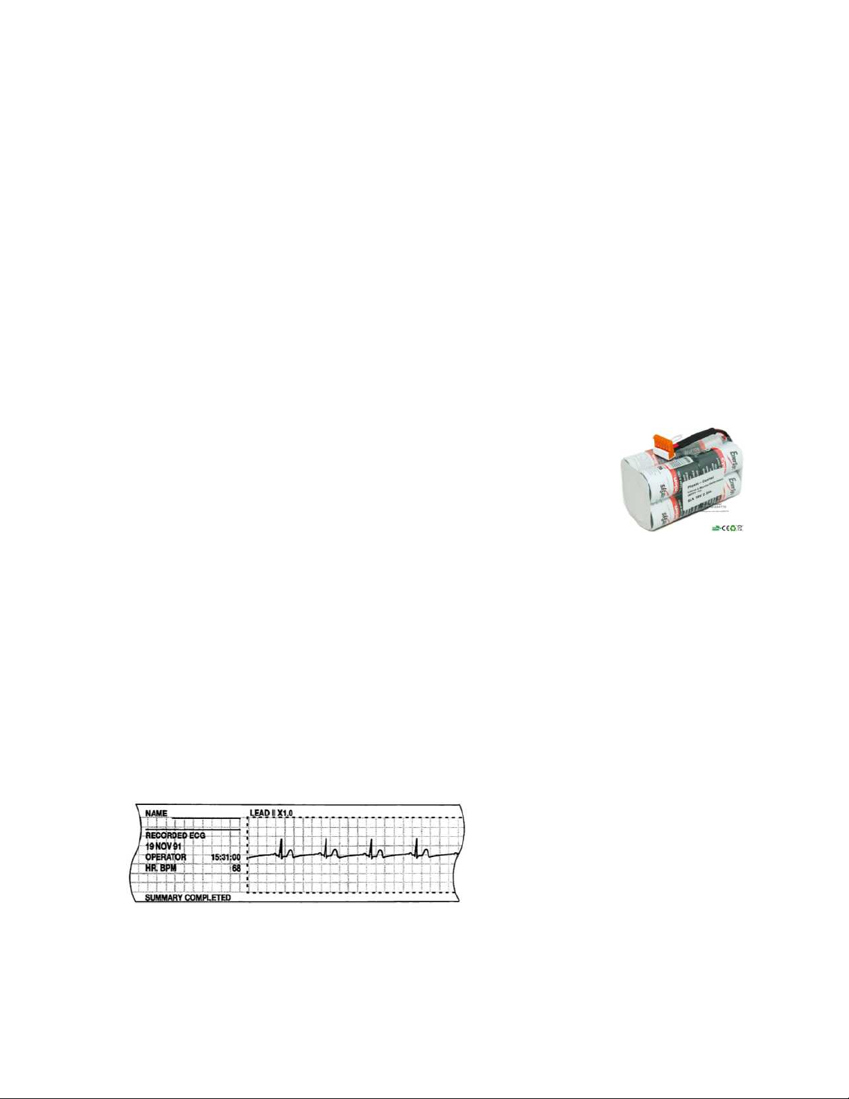
4.6. Battery (16 volt, 2500 mah) and Battery Quality -- see photo …
Frequently occuring Low Battery messages indicate the battery may need
to be replaced. If a “Service” indicator lights at turn-on, turn unit off and
back on again and recheck. A general rule of thumb for defibrillators on
battery – it should deliver three successive charges of 360 joules at or
nearly the same speed as when plugged-in. This is about 10 seconds.
Monitor Run Time with Battery
“2.5 hours” for a new unit. For reference only.
Replacing the Battery --- Open and remove/replace the battery door at the bottom of the case.
4.7. Date Time Check
Verify date and time by running the recorder; info will print in the margin. To set date and time,
use the TIME/DATE MODE and SET on the rear of the unit (if necessary, see page 2-19 of
Operating Instructions).
4.8. Patient Leakage Test / Line Leakage Test
Should be done if unit was mishandled or incurred moisture. Limits for various conditions are on
page 3-17 of Service Manual.
APPENDIX
Typical Recorder Printout
 Loading...