

Page 1

LIFEPAK6
Portable Cardiac Care System
(^
Operating and Service
Manual No.
800533-01
PhysioControl
Redmond,
Cable:
PHYSIO-RED,
Manual
January
11811
Willows
Washington
206/883-1181
Telex:
1979
Road
98052
32-0166
\
Page 2

c
SERIAL
LIFEPAK®
Corporation, 11811 Willows Road,
and
Physio-Control®
NO.
are
trademarks
Redmond,
of the
Washington 98052
Physio-Control
,//^%'
Page 3

Due
to
continuing
figurationofthis
pages
historical
the
of
mation
detailed
or
impactedbya
form
that
pages
the
effected.
page,apage
sectionatthe
information
Physio-Control,
CHANGE
design
instrument
update
may
particular
will
Each
design
log
all
individual
and
withnodateisan
rearofthis
concerning
Redmond,
changes,
Washington.
SUMMARY
additionofoptions
change.
This
form
changeorupdate.
changes,
change
manual
with
page
original
for
any
contact
the
will
page.
interim
your
available,
will
accompany
Thisisa
dateofthese
be
datedatthe
Check
the
change
changes.
Service
Representative
the
con
any
change
continuing
changes
and
bottom
infor
For
more
CHANGE
May 1978
Jar..
1979
DATE
PAGES
Front
2-19,
3-16/3-17,
3-35/3-36, 3-38
thru
3-58/3-59, 4-1
4-16, 4-18
5-3
6-1
Front
iii\
2-5, 2-3,
2-21,
3-11,
3-15
3-24 thru 3-27, 3-35
thru
3-47,
thru 3-53, 3-55,
3-57 thru
3-61,
4-10 thru
4-13, 4-19, 4-29,
4-41
4-18A, 4-13B, 4-42
thru
EFFECTED
page,
3-7/3-8,
3-26/3-27,
3-43,
thru
thru
1-4 thru
thru
3-42,
(added
4-46)
3-47/3-08,
5-64
6-24
page,
3-7 thru
3-12,
3-40,
4-2 thru 4-5,
i,
2-10,
3-14,
3-19,
3-44,
3-51
3-59,
4-16,
pages
thru
ii,
1-7,
2-12
3-9.
3-21
REASON FOR
Pages
reflect the
figuration
changes
IV)
SectionVupdated
new
lists
Section
added
schematic
applicable.
Pages
to
configuration
functional
(SectionsIthru
of
text
(SectionsIIthru
drawings
as
applicable.
VI
engineering
of
text
reflect
CHANGE
updated
latest
and
functional
and
updated
drawings
updated
the
latest
and
changes
EFFECTIVITY
to
con
with
parts
and
as
IV).
5-2
thru
5-65
SectionVupdated
bly
lists
drawings
as
and
applicable.
assem
parts
Page 4

CHANGE
SUMMARY
(Continued)
CHANGE DATE
Jan. 1979
(continued)
PAGES EFFECTED
6-1 thru 6-33
REASON
FOR CHANGE
SectionVIupdated
and
added
waveforms
applicable
and/or
voltages.
schematics
test
point
EFFECTIVITY
Page 5

TABLE
OF
CONTENTS
SECTION
I.
II.
PAGE
LIST
LIST
INTRODUCTION
1-1
1-2
1-3 General 1-1
1-4
1-5 DC Defibrillator Module 1-3
1-6
1-7
1-8 DC Defibrillator Module 1-3
1-9
OPERATION 2-1
2-1 General 2-1
2-2 Controls and Indicators 2-1
2-3
2-4 Module Connection 2-10
2-5
2-6
2-7 DC Defibrillator Module 2-12
2-8
2-9
2-10
2-11
2-12
OF
ILLUSTRATIONS
OF
TABLES
Scope
Physical
Description
Cardioscope/Recorder
Features
and
Functional
Cardioscope/Recorder
Synchronized
Operating
Input
Power,
Instructions
Cardioversion
AC
or
Cardioscope/Recorder
Synchronized
Operator
Operational
Recorder
Recorder
Cardioversion
Service
Checkout
Paper
Stylus
Replacement
Replacement
Module
Description
Module
DC
Operation
Module
and
Adjustment
. .
iii
iv
1-1
1-1
1-1
1-3
1-3
1-3
1-8
2-10
2-10
2-11
2-13
2-14
2-14
2-12
2-19
III. CIRCUIT DESCRIPTION 3-1
3-1 Introduction 3-1
3-2
3-3 Monitor Module Circuits 3-1
3-4 Defibrillator Module Circuits 3-3
3-5
3-6
3-7
3-8
3-9
3-10
3-11
3-12
3-13
3-14
3-15
3-16
Functional
Description
Cardioscope/Recorder
Preamplifier
Rate
Board
No-Fade
Recorder
Rate
Power
Display
Supply/Deflection
Monitor
DC
Defibrillator
Main
Board
Defibrillator
Test
Load Board 3-61
Board
Circuitry
Board
Circuitry
Board
Board
Charger
Circuitry
Charger
Circuitry
Board
Circuitry
Board
Circuitry
Board
Circuitry
Circuitry
. .
. . .
Jan.
3-1
3-6
3-6
3-12
3-24
3-34
3-34
3-38
3-44
3-46
3-46
3-57
1979
Page 6

TABLEOFCONTENTS
(continued)
SECTION
IV.
V.
MAINTENANCE
4-1
4-2
4-3
4-4
4-5
4-6
4-7
4-8
4-9
4-10
4-23
4-33
4-39
4-40
4-51
4-54
PARTS
5-1
5-2
5-3
Introduction
General
Warranty
Test
Repair
Cleaning
Component
Cardioscope/Recorder
Troubleshooting
Test
Major
DC
Defibrillator
Troubleshooting
Test
Major
Battery
LISTS
AND
General
Parts
Part
Lists
Ordering
Equipment
Techniques
Identification
Module
and
Calibration
Component
and
Calibration
Component
Maintenance
ASSEMBLY
Removal
Module
Removal
Guide
DRAWINGS
and
Installation
and
Installation
: • • •
. .
. .
PAGE
4-1
4-1
j"j
4-1
4-1
4-3
4-3
4-4
4-4
4-4
4-4
4-19
4-25
4-25
4-29
4-37
4-41
5-1
jj-l
£~|
b_1
VI.
SCHEMATICS
6-1
General
ii
Jan.
6~l
b_i
1979
Page 7

LIST
OF
ILLUSTRATIONS
FIGURE
1-1 LIFEPAK 6 1-2
1-2
2-1
2-2
2-3 DC
2-4 Module Connection 2-11
2-5
2-6
3-1
3-2
3-3
3-4
3-5
3-6 Rate Board Schematic 3-16
3-7
3-3
3-9 No-Fade Board Schematic 3-26
3-10
3-11 Recorder Board Schematic 3-35
3-12
3-13
3-14
3-15 Main Board Schematic 3-47
3-16 On-Off Control 3-49
3-17 Paddle Interlocks Path to Ground 3-56
3-18
3-19 Test Load Board Schematic 3-62
4-1
4-2
4-3
4-4
4-5
4-6
4-7
4-8
Typical
ECG
Waveform
Cardioscope/Recorder
Cardioscope/Recorder
Defibrillator
Recorder
Stylus
Block
Block
Preamplifier
Preamplifier
Rate
Rate
Beat
Cardioscope
Display
Power
Monitor
Defibrillator
Paper
Replacement
Diagram
Diagram
Placement
Cardioscope/Recorder
DC
Board
Board,
Board,
Count
Period
Block
Timing
Sensing,
(CRT)
Board
Schematic
Supply/Deflection
Charger
Board
Charger
Cardioscope/Recorder
Offset
Check
Setup
Cardioscope/Recorder
DC
Defibrillator
DC
Defibrillator
DC
Defibrillator
DC
Defibrillator
Battery
PARTS
SCHEMATIC
Voltage
LISTS
DRAWINGS
AND
Profile
ASSEMBLY
TITLE
Controls
Module
Module Controls and Indicators
Defibrillator
Schematic
Block
Diagram
Sampling
Display
Board
Schematic
Board
Module
Major
Key
Voltage
Module
Output
Major
Component
Waveforms
Component
(SECTION
and
Rear
Diagram
and
Schematic
Schematic
Component
Component
Waveforms
DRAWINGS
VI)
Indicators
Panel
Weighted
Average
Identification
Removal
Identification
Removal
(SECTION
V)
....
...
....
.
. .
PAGE
1-3
2-2
2-5
2-6
2-19
2-21
3-2
3-4
3-7
3-10
3-13
3-20
3-22
3-31
3-37
3-39
3-45
3-53
4-9
4-13
4-20
4-30
4-32
4-35
4-39
4-46
u^
iii Jan. 1979
Page 8

LIST OF TABLES
TABLE
1-1
2-1
2-2
2-3
2-4
2-5
2-6
4-1
4-2
4-3
4-4
4-5
4-6
5-1
5-2
6-1
TITLE
LIFEPAK6General
Cardioscope/Recorder
Indicators
Cardioscope/Recorder
DC
Defibrillator
Cardioscope/Recorder
DC
Defibrillator
Cardioscope/Recorder
Operational
Test
Cardioscope/Recorder
Power
Equipment
Supply
Lead
Select
DC
Defibrillator
Energy
Cardioscope/Recorder
Drawings
DC
Defibrillator
Drawings
Schematic
Verification
Select
Drawings
Specifications
Module
Module
Module
Controls
Module
Module
Operational
and
DC
Checkout
Troubleshooting
Voltage
Check
Test
Troubleshooting
Tolerances
Parts
Parts
List
List
Controls
Rear
Operational
and
Panel
and
Indicators
Checkout
Checkout
Defibrillator
•
Guide
Guide
and
Assembly
and
Assembly
....
....
PAGE
1-4
z~*
£•-$
2-7
2-15
2-17
2-18
4-£
4-b
4-11
4-1/
4-26
4-33
5-2
l~*z
b~'
/^\
IV
Page 9
SECTION
INTRODUCTION
I
1-1.
1-2
l-:3.
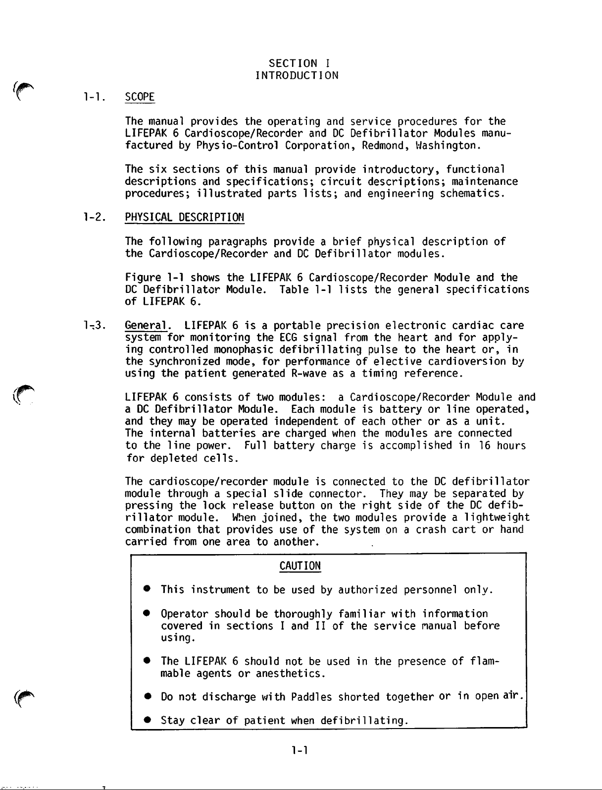
SCOPE
The
manual
provides
the
operating
LIFEPAK6Cardioscope/Recorder
factured
The
descriptions
procedures;
PHYSICAL
The
following
the
Cardioscope/Recorder
Figure
DC
Defibrillator
of
LIFEPAK
General.
system
ing
the
using
by
Physio-Control
six
sections
and
illustrated
DESCRIPTION
paragraphs
1-1
shows
6.
LIFEPAK6isaportable
for
monitoring
controlled
synchronized
the
patient
of
this
manual
specifications;
parts
provideabrief
and DC
the
LIFEPAK6Cardioscope/Recorder
Module.
monophasic
mode,
Table
the
ECG
defibrillating
for
generated
Corporation,
performance
R-wave
and
service
and
DC
Defibrillator
provide
circuit
lists;
and
Defibrillator
1-1
lists
precision
signal
from
of
as a
procedures
Redmond,
Washington.
introductory,
descriptions;
engineering
physical
description
modules.
the
general
electronic
the
heart
pulse
elective
timing
to
the
cardioversion
reference.
for the
Modules
manu
functional
maintenance
schematics.
of
Module
and
specifications
cardiac
and
for
apply
heart
or,
the
care
in
by
LIFEPAK6consists
a DC
and
The
to
The
module
pressing
rillator
combination
carried
Defibrillator
they
the
for
may
internal
line
depleted
be
batteries
power.
cells.
cardioscope/recorder
throughaspecial
the
lock
module.
that
•
This
•
Operator
covered
using.
•
The
mable
from
one
instrument
in
LIFEPAK6should
agents
operated
should
of two
Module.
are
Full
release
When
joined,
provides
area
to another.
to
be
sections
or
anesthetics.
modules:
Each
a Cardioscope/Recorder
module
is
independentofeach
charged
battery
module
slide
button
use
CAUTION
be
used
thoroughly
I and II of the
not
when
charge
is
connected
connector.
on
the
the two
of
the
system
by
authorized
familiar
be
used
the
is
right
modules
service
in
the
battery
other
modules
or
or
are
accomplished
to the DC
They may be
side of the DC
provide
on a
crash
personnel
with
information
manual
presence
Module
line
operated,
asaunit.
connected
in
16
hours
defibrillator
separated
defib
a lightweight
cart
or
hand
only.
before
of
flam
and
by
•
Do
not
discharge
• Stay clear of
with
patient
Paddles
when defibrillating.
1-1
shorted
togetherorin
open
air
Page 10

CARDIOSCOPE/RECORDER
PATIENT
CABLE
Figure
1-1
LIFEPAK
1-2
6
Page 11

1-3.
General
The
stable
(Continued)
circuitry
and
highly
inahospital
recommended.
usedinthe
reliable.
LIFEPAK6is
environment.
solid
The
instrumentissuitable
Useinan
explosive
state,
temperature
for
atmosphereisnot
use
1-4.
1-5.
1-6.
1-7•
Cardioscope/Recorder
continuous
ing
or
hard
copyofthe
display
througharecorder
cardioscope/recorder
ing
the
heart
internal
5-lead
DC
Defibrillator
to
deliveracontrolled
paddles,orthrough
fully
patient's
(optional
provided
or
through
FEATURES
The
cardioscope/recorder
with
AND
following
rate
shielded
heart
500
withadelivered
joules).
the
the
limited
FUNCTIONAL.DESCRIPTION
paragraphs
Cardioscope/Recorder
easily
described
accessible.
and
illustratedinSection
Module.
through
The
eitherano-fade
display
information
module
from
cable.
Module.
displayedonthe
also
signals
externally
TheDCdefibrillator
monophasic
The
pulse
unitaswellaswith
delivered
provideafunctional
and
DC
defibrillator
Module.
The
location
All
waveformisdisplayedoneither
which
from
at
mentationat25
on
4
4
is
are
drivenbyelectrical
external
25
mm/sec.
the
monitor
seconds
second
shieldedtoreject
memory
overloading
The
mm/sec.
panel,
from
real
and
signals.
recorder
the
time.
provides
By
activating
recorder
In
canbeused
radio
frequency
networks
effect,
cardioscope/recorder
cardioscope
allowing
the
usertoobtain
cardioscope.
provides
detected
for
computing
through
applied
Quik-Look
electrodes
provides
defibrillating
energy
contentof5
pulsetothe
maybedelivered
energy
pediatric,
internal,
anterior-posterior
spoon
to
with
provides
for
monitor
The
and
display
paddles,
and
the
means
400
joules
the
paddles
shaped
descriptionofthe
modules.
controls
and
function
II.
the
no-fade
The
real
are
clearly
of
all
The
patient
cardioscopeorrecorder
designed
for
cardioscope
time
the
diagnostic
Delayed
labelled
controls
generated
fast
trace
docu
Record
recovery
sweeps
switch
documentationisdelayedbyabout
this
for
monitoring
provides
purposes.
interference.
the
user
The
with
a
a
a
paddles.
and
are
ECG
a
circuitry
When
monitoringapatient's
the
inputiscompletely
be
obtained
adjustable
the
cardioscope
The3digit
beats-per-minute
BPM
limit
are
exceeded,anaudio
additional
a
one
volt/millivolt
availableatthe
millivolt
gain;alow
for
freezing
indicator.
from
the
volume
heart
controlisprovided
or
rate
(BPM)
alarm
features
calibration
capabilities
ECG
battery
the
ECG
ECG
wave-form
protected
DC
defibrillator.Asystole
from
high
for
recorder
monitor
from20to
alarm
are
andaone
OUT
switch
voltage
signalonthe
cannot
be
watched.
providesacontinuous
300
BPM.
are
provided.Ifthe
systemistriggered.
includedinthe
millivolt/millivoltinreal
jack
locatedonthe
(CAL)isprovidedtocalibrate
level
indicator;amomentary
cardioscope;
1-3
through
voltage
audible
Adjustable
cardioscope/recorder
back
the
patient
levelsasmay
beeper
monitoring
pre-set
The
panel;aone
with
display
low
and
BPM
following
time
the
when
of
unit:
freeze
andabattery
charging
cable,
high
limits
is
ECG
switch
Page 12

TABLE
1-1
LIFEPAK
CHARACTERISTIC
CARDIOSCOPE/RECORDER MODULE
•
SIZE
• WEIGHT
•
CARDIOSCOPE
• COMMON MODE REJECTION
• CALIBRATION
(envelope)
DISPLAY
Sweep
Bandwidth
LOW BATTERY INDICATOR
Speed
(-3dB)
(CRT)
6 GENERAL SPECIFICATIONS
♦QUANTITY
OR SPECIFICATIONS
10.75"xl2"x4.5"
15
pounds
3
inch
25
mm/sec.
0.5 Hz to 30 Hz
72 dB minimum with
isolated
misbalance
Indicates
level
Internal1mV
pushbutton
instrument.
(6.8
x 4
inch
+ 1 mm
ground
at 60
approximate
of
battery.
switchtocalibrate
calibration
(27.3x30.5x11.4cm)
kg)
(7.62cmxl0.16cm)
respect
(with
Hz).
5 K
to
ohms
voltage
(CAL),
•
RATE
METER
• ECG
•
•
OUTPUT
INPUT
SYSTOLE
BATTERY CHARGING INDICATOR
(Heart
BEEPER
Rate)
(QRS)
3
digit
displayofthe
20
Adjustable
(audio)
1
volt/millivolt
millivolt,
Note:
1)
2)
to
readout
300
beats-per-minute
high
provides
R-wave
and
low
rate
alarms.
and1millivolt/
CSA units do not have this
ECG OUTPUT function.
Obtained
cable,
paddles.
or
0.05
Hz
through
through
to 100
a 5
QUIK-LOOK
Selectablebyrotary
any
one
of
nine
standard
figurations
(Paddles,
rate
AVR,AVL,AVF,V,STD).
Adjustable
acts as threshold control.
Illuminates
charging.
accomplishedin16
depleted
Volume.
when the
Full
cells.
ECG
battery
battery
hours
for
from
(BPM).
limit
Hz.
lead
switch
in
con
I,II,III,
size
charge
control
is
is
for
1-4
Jan. 1979
Page 13

TABLE
1-1
(Continued)
LIFEPAK
CHARACTERISTIC
CARDIOSCOPE/RECORDER MODULE
O
POWER
SOURCE
Battery
Capacity
AC
•
RECORDER
Sweep
Bandwidth
Input
Power
Speed
Power
Consumption
DISPLAY
(3
dB)
6
GENERAL
SPECIFICATIONS
♦QUANTITY
Nickel
Cadmium
Cardioscope
min.
at
-10°C.
Recorder
at 250C.
115+12
230
12
watts
30
watts
set
Paper
25
mm/sec
0.05
0.5
Monitoring,1hour
VAC,
VAC,
50
during
during
to
maximums.
Size
(fixed)
to
100
to
40
OR SPECIFICATIONS
Battery,
Monitoring,
60
Hz
(or
Hz).
cardioscope
recording
43
mmx30m(100
Hz
(Real)
Hz
(Delayed)
14.4V
2.5
1.5AH
hours
min.
optional
monitoring.
with
heat
ft.)
e
FREEZE
DEFIBRILLATOR
c
SIZE
e
WEIGHT
©
WAVEFORM
•
OUTPUT
O
CHARGE
•
LOW
SWITCH
(envelope
ENERGIES
TIME
BATTERY
MODULE
(Delivered)
INDICATOR
Momentary
freezinq
CRT.
19.25x12x4.5
(48.9x30.5x11.4
19.25
Monophasic
pushbutton
QRS
complex
inches
switch
observed
cm)
pounds
(8.6
kg)
Pulse,5milliseconds
(Edmark)
5,10,20,30,50,100,2-0,300,400
joules
Internal
joules
(Optional
paddles:
(Higher
energies
500
joules).
5,10,20,30,50
cannot
chargedordelivered).
To 400
seconds.
(Optional)to500
seconds.
Indicates
level
joules
approximate
of
battery.
in
less
joules
than 10
in
voltage
for
on
be
12.5
9
—^—^————^___—___
OUTPUT
Electrode
Cord
PADDLES
Length
Size
32
cm2
Extended
1-5
Length
10
feet.
Jan.
1979
Page 14

TABLE
1-1
(Continued)
LIFEPAK6GENERAL
CHARACTERISTIC
DEFIBRILLATOR MODULE
• BATTERY CHARGING INDICATOR
• POWER SOURCE
Battery
Capacity
AC
Input
• CHARGE CONTROLS
Power
Power
Consumption
SPECIFICATIONS
♦QUANTITY
Illuminates
charging.
OR
when
Full
SPECIFICATIONS
battery
battery
accomplishedin16
depleted
Nickel
Using
discharges
15-400
at -10OC.
115+12
230
25
watts
250
Nine
presetting
energy.
initiates
preset
pushbutton
automatic
cells.
Cadmium
battery
minimumat25°C.
joule
VAC,
VAC,
watts
50
when
during
position
Pushbuttononfront
automatic
level.
chargingtopreset
Battery,
pak,
discharges
60
Hz)
power
rotary
the
desired
Paddle
(on
APEX
hours
25-400
Hz
(or
on.
defib
charging
paddle
is
charge
for
12V
1 AH
joule
minimum
optional
charge.
switch
for
discharge
mounted
initiates
is
panel
to
level).
• ISOLATED OUTPUT
• DISCHARGE CONTROL
• DEFIBRILLATOR SYNCHRONIZER
Synchronized
pulse
version timed to occur on
the
R-wave which follows
rillate command.
Sync
Sensitivity
for
first
Indicator
defibrillating
elective
cardio
patient-generated
defib-
Control
Defibrillator
isolated.
Pushbutton
both
accidental
on
paddlesinseriestoprevent
control
internal
Marker
sync
on
trigger
pushbutton
output
discharge
discharge.
panel
paddles.
CRT
trace
point.
switch
for
will
systoletoindicate
ECG size control
control.
acts as threshold
electrically
controls
Pushbutton
use
identifies
The
flash
only
SYNC
on
on
in
synchronization
1-6
Jan.
1979
Page 15

TABLE
LIFEPAK 6 GENERAL SPECIFICATIONS
1-1
(Continued)
CHARACTERISTIC
DEFIBRILLATOR MODULE
©
DEFIBRILLATOR
Sync-Defib
GENERAL
Line
Cord
Switches
ENVIRONMENTAL
Unless
met
otherwise
under
the
SYNCHRONIZER
Mode
CONDITIONS
stated
following
Control
the
storage
(Cont'd.)
performance
and
operating
♦QUANTITY
Pushbutton
to
change
to
Defib
Each
ten
foot
low
capacitance
hospital
Separate
vided for monitor and defibrillator
modules.
OR SPECIFICATIONS
switch
mode
or Defib to
Module
instantly
is
provided
special
duty,3prong
ON-OFF
can
be
Sync.
low
leakage,
cable
with
connector.
switches
depressed
from
with
special
are
requirementsofLIFEPAK6shall
conditions.
Sync
pro
be
•
ATMOSPHERIC
•
RELATIVE
•
VIBRATION
SHOCK
requirements
•
DROP
operator
(capableofmeeting
TEST
drop).
•
PADDLE
operational
TEMPERATURE
HUMIDITY
(without
or
DROP
PRESSURE
after
patient
TEST
and
(capable
safety
RANGE
ODerating
shock).
resulting
hazard
in
during
of
meeting
requirements).
400 mm
0
to
MIL-STD-810C,
cedure
V.
30
sine,
direction)
mutually
1
concrete floor on each axis
(6
1
FDA-MDS-021-0001, fifth
paragraph
0°C to
-30°Cto+65°C
Hg
95%
VIII,
g's,
18
1/2
foot
drops).
Meter
to
772
mm
Hg
(non-condensing)
11
- 1
impact
along
Method
Figure
milliseconds,half-
514.2,
514.2-6,
shocks(3in
each
perpendicular
drop
Benchmark
(45.7
(3.281
4.3.2.
55°C
Operating
Storage
of
axes.
cm)
draft,
three
feet)
on
Pro
Curve
each
a
per
♦
Specifications
specifications
subjecttochange
at
25°C.
without
1-7
notice.
Unless
otherwise
Jan.
1979
stated
all
Page 16

DC
Defibrillator
defibrillator
are
Module.
described
The
locationofall
and
illustratedinSection
controls
for
II.
the
1-9
FeaturesontheDCdefibrillator
the
stateofchargeofthe
voltage
200
charging
hiqh
the
discharged
Look
available
positions
capableofbeing
Synchronized
level
indicator;atest
joulesorgreaterisdeliveredtothe
indicator.Acharge
voltage
capacitor
paddlesorthrough
defibrillating
from
through
from
ranging
the
the
theDCdefibrillator
from5to
rechargedto400
Cardioversion.
provideasynchronized
pulse
milliseconds
atrial
using
is
the
causes
deliveryofthe
after
flutterorother
the
R-waveasthe
deliveredata
ECG
cycle
where
the
time
electrical
charge
charging
chestofa
internal,
trigger
marker
arrhythmias.AsshowninFigure
initiating
which
include:aready
storage
load
storage
pulse.Oncommand,
circuitry
patient,
spoon
400
joules
joulesinless
The
functionofthis
pulsetothe
defibrillating
pulse
signal,
avoids
shock
flasher
capacitor;alow
indicator
test
which
load;
andabattery
capacitoristhe
relays
and
the
resultant
through
shaped
canbeadjustedinnine
delivered.
the
paddles.
The
indicating
battery
will
flash
sourceofthe
disconnect
external
The
instrument
than10seconds.
circuitisto
LIFEPAK6.This
pulseatapoint
for
converting
the
the
vulnerable
may
cause
atrial
fibrillation,
1-2,
defibrillating
T-wave
portion
ventricular
it
_
pulse
is
Quik-
energy
discrete
is
trigger
20
by
pulse
of
fibrillation
ll.£
PAI
FIGURE
Pl.'SHBl'TTt
DEPRESSED
1-2
TYPICAL
ECG
DEFIBRILLATING PULSE
TRIGGERED BY DEFIBRILLATOR
SYNCHRONIZER CIRCUIT
t
TIME
WAVEFORM
Page 17

SECTION
OPERATION
II
rthe
2-1.
2-2. CONTROLS AND INDICATORS
1)
2)
3)
GENERAL
This
and DC Defibrillator Modules.
The
and
The
shown
to
or
of each control or indicator.
ECG
listing
and
The
in
or
of
section
and
provides
following
indicators
controls
in
the
corresponding
indicator
Figure
2-2
recording.
in
briefly
controls
Figure
corresponding
indicator
each
control
provides
operator
paragraphs
on
and
indicators
Figure
2-1.
placarded
provides
Each
Table
describes the
2-3.
2-2.
and
indicators
Each
placarded
or
LIFEPAK6Cardioscope/Recorder
listing
the
item
control
listing
indicator.
information
service
for
provideabrief
for
the
Each
control
in
Table
nomenclature
rear
The
nomenclature
panel
is
keyed
table
function.
in
lists
for
the
and
indicatoriskeyed
Table
and
procedurestoproperly
the
LIFEPAK6Cardioscope/Recorder
descriptionofthe
and
DC
Cardioscope/Recorder
and
indicatoriskeyedonthe
2-1.
and
view
on
the
DC
2-3.
and
the
The
table
briefly
of
the
figure
describes
connections
to
item
placarded
Defibrillator
The
table
briefly
lists
describes
lists,
the
corresponding
Module
on
the
operate
controls
Defibrillator.
Module
the
the
for
nomenclature
are
figure
the
control
the
are
figure
control
functions
external
shown
to
functions
2-1
Page 18

FIGURE
2-1
CARDIOSCOPE/RECORDER MODULE CONTROLS AND INDICATORS
2-2
Page 19
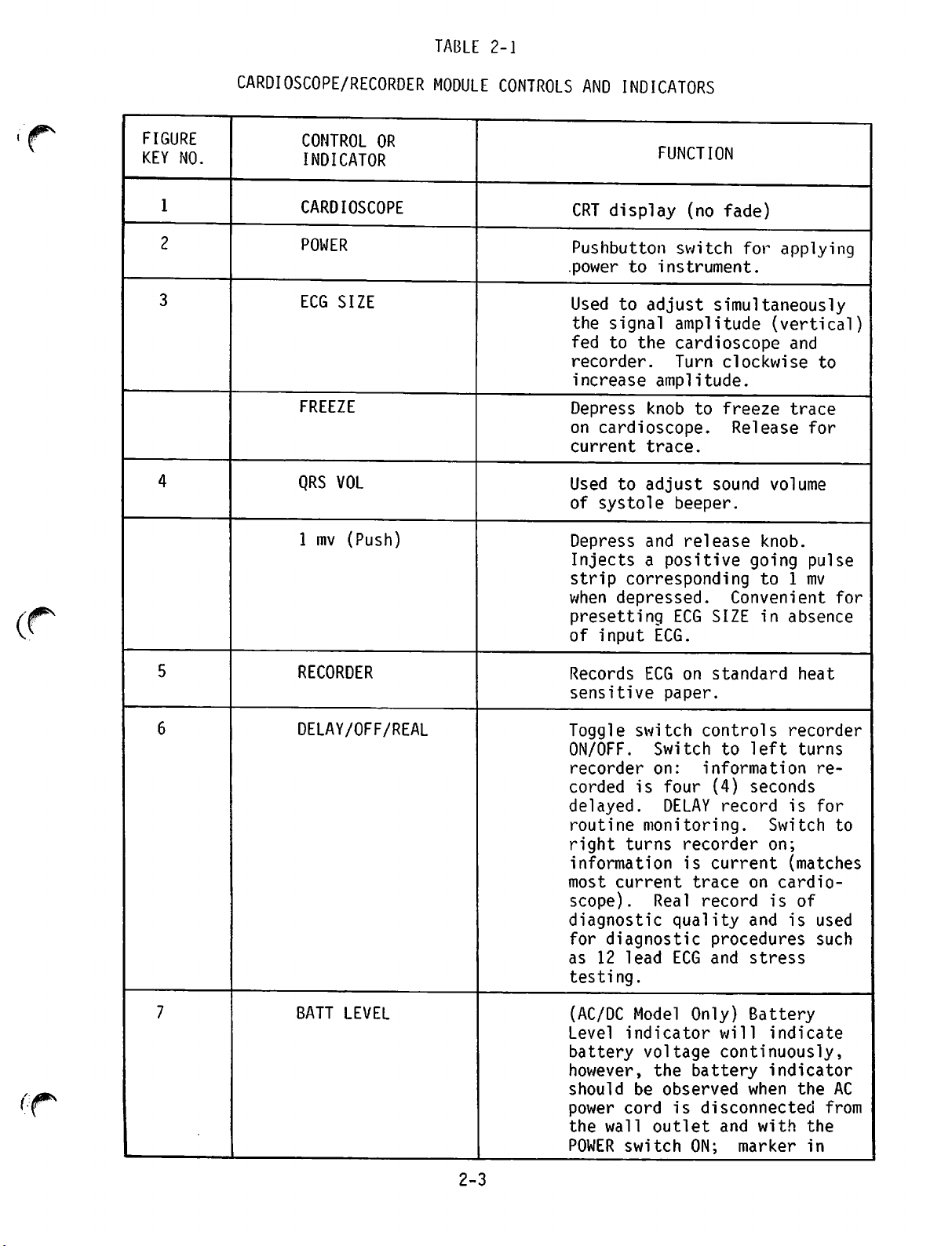
TABLE 2-1
.-JpN
FIGURE
KEY NO.
1
2
3
4
CARDIOSCOPE/RECORDER
CONTROL
INDICATOR
CARDIOSCOPE
POWER
ECG
FREEZE
QRS VOL
1
mv
OR
SIZE
(Push)
MODULE
CONTROLS
.power
AND
INDICATORS
FUNCTION
CRT
display
Pushbutton
(no
switch
fade)
for
applying
to instrument.
Used
to
the
signal
fed
to
the
recorder.
increase
adjust
amplitude.
simultaneously
amplitude
cardioscope
Turn
clockwise
(vertical)
and
to
Depress knob to freeze trace
on
cardioscope.
current
trace.
Release
for
Used to adjust sound volume
of
systole
Depress
Injectsapositive
strip
when
corresponding
depressed.
presetting
of
input
beeper.
and release
Convenient
ECG
SIZE
ECG.
knob.
going
to 1 mv
in
absence
pulse
for
/'jJP^
5
6
RECORDER
DELAY/OFF/REAL
Records
sensitive
Toggle
ON/OFF.
recorder
corded
delayed.
routine
right
ECG
on
standard
paper.
switch
controls
Switch to left turns
on:
is
information
four
(4)
seconds
DELAY record
monitoring.
turns
recorder
informationiscurrent
most
current
scope).
diagnostic quality and
for
diagnostic
as 12
lead
Real
ECG
trace
on
record
procedures
and
stress
heat
recorder
is
Switch
on;
(matches
cardio
is
of
is
re
for
to
used
such
testing.
7
BATT
LEVEL
(AC/DC
Level
battery
however,
should
power
the
POWER switch ON; marker in
Model
indicator
Only)
wil1
Battery
indicate
voltage continuously,
the battery indicator
be
observed
when
the
cord is disconnected from
wall
outlet
and
with
the
AC
2-3
Page 20

TABLE
2-1
(Continued)
'/^\
FIGURE
KEY
NO.
7
(cont'd.)
8
9
10
CARDIOSCOPE/RECORDER
CONTROL
INDICATOR
BATT
BATT
ECG
PATIENT
LEVEL
CHG
LEAD
OR
(Continued)
SELECT
CONN
MODULE
CONTROLS
AND INDICATORS
FUNCTION
green
voltage
half
depleted
charged
necting
wall
(AC/DC
will
pak
Rotary
desired
half
indicates
adequacy,
indicates
battery
in 16
power
outlet.
Model
illuminate
is
charging.
switch
paddles
patient cable
II,
III,
AVR, AVL, AVF and
Connections
patient
cable.
low
hours
cord
Only)
for
leads;
for
battery
marker
battery.
can
be
by con
to
Indicator
when
input
six
battery
selecting
STD,
(6)
in
red
fully
grounded
or
I,
V.
pin
A
11
12
13
QRS
HEART
ALARM
RATE
LIMITS
Indicator
sensed.
Digital
from
20 to 300
minutes
dates
Switches
LOW
heart
Violation
will result in a continuous audio
alarm. To
control
flashes
display of QRS
beats-per-
(BPM).
ewery
for
rate
of
silence
knobs
Heart
3.5
seconds.
selecting
limits.
these
to
when QRS
rate
preset
alarm
OFF.
rate
up
HIGH
limits
turn the
and
^\
2-4
Page 21

Ksoumn
CAimo*—rerr
TO INSTRUCTION
MANUAL BEFORE
CONNECTING
ACCESSORY
El
|;
CSA
Figure
units
I
FIGURE
KEY NO.
1
2
*Note:
2-2
CARDIOSCOPE/RECORDER
TABLE
CARDIOSCOPE/RECORDER
CONTROL
INDICATOR
ECG
POWER
do not
OR
OUTPUT
CORD
*
have
this
2-2
MODULE
ECG
output
MODULE
REAR
ECG
REAR
PANEL
output
monitoring
Connect
function.
PANEL
FUNCTION
jack
equipment.
to
wall
for
external
receptable.
2-5
Jan.
1979
Page 22

FIGURE
2-3
DC
DEFIBRILLATOR
MODULE
2-6
CONTROLS
AND
INDICATORS
Page 23
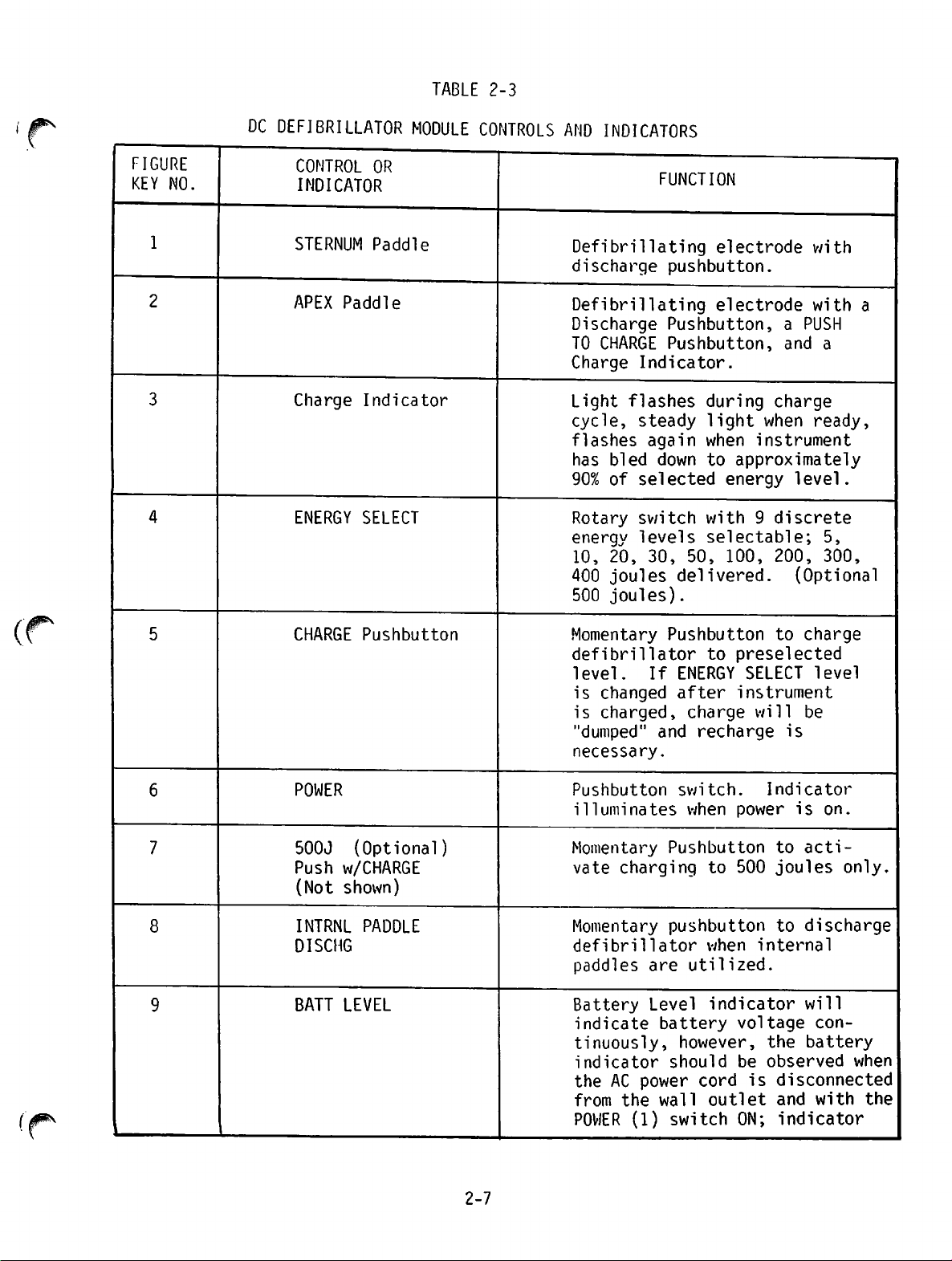
TABLE
2-3
J^*\
FIGURE
KEY NO.
1
2
3
4
DC
DEFIBRILLATOR
CONTROL
INDICATOR
STERNUM
APEX
Paddle
Charge
ENERGY
MODULE
OR
Paddle
Indicator
SELECT
CONTROLS
AND
INDICATORS
FUNCTION
Defibrillating
discharge
Defibrillating
Discharge
TO CHARGE Pushbutton, and a
Charge
Light
cycle,
flashes
has
90%
Rotary
energy
10,
400
500
Indicator.
flashes
steady
again when
bled
down to approximately
of
selected
switch
levels
20,
30,
joules
joules).
electrode
pushbutton.
electrode
Pushbutton,aPUSH
during
light
charge
when
instrument
energy
with 9
level.
discrete
selectable;
50,
100,
delivered.
200, 300,
(Optional
with
with a
ready,
5,
5
CHARGE
Pushbutton
Momentary
defibrillator
level. If ENERGY
is
changed
is
charged,
"dumped"
necessary.
6
POWER
Pushbutton
illuminates
7
8
500J
Push w/CHARGE
(Not
INTRNL
DISCHG
(Optional)
shown)
PADDLE
Momentary
vate
charging
Momentary
defibrillator
paddles
BATT
9
LEVEL
Battery
indicate
tinuously,
indicator
the
AC
from the wall outlet and with the
POWER
Pushbutton to charge
to
preselected
SELECT
after
charge
and
switch.
when
Pushbutton
pushbutton
are
Level
instrument
will
recharge
power
to
500
when
internal
utilized.
indicator
Indicator
to
joules
to
battery voltage con
power
(1)
however,
should
cord
switch
the
be
observed
is
disconnected
ON;
level
be
is
is
on.
acti
only.
discharge
will
battery
when
indicator
2-7
Page 24

DC
DEFIBRILLATOR
TABLE
2-3
(Continued)
MODULE CONTROLS
AND
INDICATORS
FIGURE
KEY NO.
(Cont'd)
10
11
CONTROL
INDICATOR
BATT
BATT
SYNC
LEVEL
CHG
OR
(continued)
FUNCTION
will
marker
be
connecting
grounded
Indicator
being
Momentary
select
ton
with each
defibrillate
mode,
indicate
in
battery
in red half indicates low
voltage
battery.Adepleted
fully
chargedin16
wall
battery
green
half
adequacy,
AC
power
outlet.
indicates
condition,
indicates
battery
hours
cord
battery
charged.
pushbutton
synchronized
will
illuminate
QRS.
To return to
switch
mode.
and
(asynchronous)
depress
button
again.
marker
to
But
flash
can
by
is
to
OFF
Defibrillatorisautomatically
in
defib mode when instrument
is
turnedonand
returns to defib mode after
discharge
connected from monitor.
or
automatically
if
unit
is
dis
13
14
15
16
12
Discharge
Pushbutton
Test Load Indicator
Test
Power
Paddle Connector
Load
Cord
Discharge
paddles
Pushbuttons
must
be
depressed
on
both
simultaneouslytodischarge
defibrillator.
be
delivered
ment
Indicator
or
test
less
50
Metal
energy
is
fully
flashes
greater
load.
than
ohm
is
100
defibrillator
contacts
pulse
Connecttowall
Connector for external
internal
paddles.
Energy
unless
the
will
instru
chargedor"ready".
when
discharged
Will
not
joules
for
from
paddles.
200
into
flash
is
delivered
test
load
receiving
receptacle
or
not
joules
when
2-8
Jan.
1979
Page 25

DC
DEFIBRILLATOR
TABLE
2-3
MODULE
(Continued)
CONTROLS
AND
INDICATORS
FIGURE
KEY NO,
17
CONTROL
INDICATOR
Power
LP6
Receptacle
Monitor
OR
for
FUNCTION
Connector
Cardioscope/Recorder
when
operatedorcharging
batteries from one power source
both
for
connecting
units
are
Module
to
be
the
the
line-
2-9
Page 26

2-3.
OPERATING INSTRUCTIONS
The
following
the
LIFEPAK6cardiac
cautions
•
•
•
while
This
Operator
covered
The
agents
paragraphs
operating
instrumentisto
should
in
SectionsIand
LIFEPAK6should
to
anesthetics.
provide
care
be
instrument.
the
CAUTION
be
thoroughly
not
brief
operating
instrument.
used
by
authorized
familiar
II
of
this
be
used
in
Observe
with
service
the
presence
instructions
the
following
personnel
information
manual
only.
before
of
flammable
for
using
2-4.
• Do not
•
Stay
•
Do
•
Keep
(wet
the
charge.
• Do
energy
If
diathermy
Module
DC
defibrillator
separated
of
the
and
electrical
When the modules are
exposed.
used
only to
signal
the
synchronized
recorder
present
discharge
clear
not
of
discharge
defibrillator
or
dry)
presentahazardous
paddle
not
fibrillation
Connection.
again
defibrillator.
electrodes
operate
electrical
prior
module
by
connections
These exposed
transfer
from the DC
mode,
to the DC
at these
contacts.
with
patient
paddles
when
defibrillator
paddles
and
the
defibrillator
fields
occurs
to
turning
The
cardioscope/recorder
throughaspecial
pressing
The
such
where
the
slide
between
separated,
contacts
the
paddle
defibrillator
the
trigger
defibrillator.
shorted
defibrillating.
into
clean.
user
in
the
as
diathermy
on
defibrillator.
lock
release
connector
the
the
electrical
do
not
pickup
to the cardioscope/recorder or
pulse
No
together.
open
air.
Paddles
electrical
during
presence
those
two
represent
of the low
from
dangerous
defibrillator
generated
is
in
module is connected to the
slide
button
makes
modules.
slide contacts are
the
covered
with
pathway
of
strong
by
use,
connector.
both
a safety
cardioscope/
voltages
turn off
on the
the
Refer
level
between
diathermy.
right
mechanical
to
hazard
ECG
are ever
jel
dis
high
They may
side
Figure
and
in
be
2-4
are
2-5.
1)
2)
Input
For
grounded
To
to a
operate
power
Power,
AC
operate
three
cord
AC or DC
operating
power
source.
AC/DC
pin
grounded
AC/DC
instrument
from
Operation.
instrument,
connect
Do not use
instrumentonAC
power
on
the
the
three
pin
2-10
adapter.
input
source.
internal
grounded
power
cord
power,
Do not use
battery,
outlet.
toathree
connect
adapter.
disconnect
Turn
POWER
pin
power
switch
Jan.
cord
To
the
1979
Page 27

Slide
Connection
Figure
2-4
Module
Release
Connection
(,.
2-5
'
2-6.
1}
2)
3)
4)
InputPovier^M^^L^m^^
to
ON
and
observe
the
"green"
Hot.:
C^c^Re^^
^^^^TI^^
Refertoparagraph
ational
zone
When
instant
rechargedin16
checkout.
^fused!^
be
connected
Attach
Turn
Depress
either
ECG
LEAD
POWER
the
BATT
LEVEL
which
indicates
is
connected
hours.
2-10
for
ui
•
4-0
^^"cSySSS^Tnd
together.
patient
SELECT
pushbutton
cable
switch
switch_on1_______
(Continued)
^
adequate
operatui
DATTFNT
or
paddles
to
position
CAUTI
b^^^
oakery
t<>
the
AC
input.
service
CONN
to
which
If
QUIK-LOOK
DC
dSfltrlll.tor
patient.
desired.
he
in
power^the
includes
an
oper-
paddlesa)e
,™st
when not in
5)
-^J22t-^Ji^
if
recorder
switchtothe
use.
monitoringisdesired,
position
madeinthe
• a -^
desired.
DELAY
switch
2-11
,ri<»st
adjust
position.
the
the
recorder
DELAY/REAL
.pfihril
Page 28

2-6.
Cardioscope/Recorder
Module
(Continued)
6)
7)
8)
9)
10)
Depress
a
10mmsquarewave
cardioscope.
Adjust
on
Adjust
Note:
If
HIGH and LOW limits.
Note:
If
CAL
momentary
ECG
SIZE
controltoobtain
cardioscope
SYST
When
each
useofthe
Audible
exceeded.
limit
desired,
For
patient
to
the
combination with LIFEPAK 6 has been evaluated for fire
and
shock
and/or
VOL
controltodesired
volumeisadjusted,
QRS
complex.
ALARM
alarm
adjustments
connect
safety
ECG
OUTPUT
hazard.
pushbutton
switch,
displayonrecorderora
desired
recorder.
volume.
"beeper"
LIMITSisdesired,
is
continuous
To
turn
off
alarm,
beyond
external
do
not
jack
the
monitoring
CAUTION
connect
unless
adjust
when
accessory
preset
move
patient's
equipment
accessory
adjust
ECG
convenient
patient
should
the
limits
the
HIGH
rate.
equipment
SIZE
control
displayonthe
generated
coincide
controls
and/or
to
equipment
are
the
in
with
ECG
ECG
for
LOW
for
display
proper
OUTPUT
O
jack
11)
2-7.
1)
2)
3)
Depress
is
desired
Note:
DC
Defibrillator
operating
using
2-10
Press
Note:
Select
Depress
front
Note:
FREEZE
If
FREEZE
recording
depressed
to
real-time
information will be recorded and the unit then returns to
DELAY
instructions
the
paddlesisdiscussedinparagraph
for
operator
POWER
If
operating
indicator
desired
and
panel
If
the
w/CHG
CHARGE 3
switch
to be studied.
while
mode.
Module.
on
switchisdespressed
continues
recordinginDELAY
until
for
service
1
release
or on
switch
on
to
insure
energytobe
CHARGE
APEX
(optional)
pushbutton
pushbutton.
internal
paddle.
front
The
to
500
switch
panel;ifthe
while
uninterrupted.
FREEZE
is
released.
following
LIFEPAK6DC
includinganoperational
on.
adequate
delivered
3
Button
battery
battery
with
pushbutton
joulesisto
must
be
pushed
recording
If
mode,
paragraphs
Defibrillator.
2-6.
will
power,
voltage.
ENERGY
switch
be
ECG
signal
FREEZE
recording
At
that
on
in
switch
time,
provide
Monitoring
Refer
checkout.
illuminate.
check
SELECT
either
delivered,
simultaneously
to
BATT
the
cardioscope
REAL
mode,
is
reverts
frozen
brief
paragraph
LEVEL
2
on
switch.
defibrillator
500J
with
PUSH
the
Indiscriminate
cause
is
cardiac
not
recommended.
use of
damage.
CAUTION
energy
Automatic
(See
Operators
2-12
settings
selection
above
Instruction
400
of
maximum
joules
Manual).
may
energy
Jan.
1979
Page 29

2"7-
DC
Defibrillator
Module
(Continued)
4)
5)
6)
Place
DC
flashing
fully
Note:
Depress
shock.
paddles
firmlyonpatient's
defibrillatorisreadytofire
and
glows
charged
Once
and
is
bleed
level,
instrument
If
changed
automatically
instrument to
both
to
the
the
ready
down.
the
the
Stay
paddle
steady.
preset
defibrillator
charge
to
CHARGE
must be
ENERGY
while the
clear
level.
indicator
fire.
When
SELECT
dumped.
defibrill
of
discharge
If
the
indicator
recharged
defibrillator
patient
chest.
when
DC
defibrillator
has
charged
stops
not
fired,
charge
switch
It
is
ate at a different
CAUTION
when
pushbuttons
red
to
flashing,
the
reaches
will
is
begin
before
inadvertently
is
charged,
necessary
defibrill
simultaneously
CHARGE
will
the
desired
the
charge
90%
of
to
flash
using.
to
recharge
setting.
ati
indicator
not
fire
instrument
will
the
or
the
ng.
stops
unless
level
slowly
selected
and
the
intentionally
charge
the
for
is
counter-
<r
7)
8)
9)
If
repeat
and
repeat
To
dump
on
defibrillator
For
internal
the
instrument
separate
and
the
A.
To
illuminate.
B.
Select
(Delivered
internal
Note:
C.
Depress
Defibrillatorisready
and
D.
Depress
counter
as
above.
charge
from
connector
defibrill
and
front
defibrillation
(the
the
ate.
desired
energy
paddles).
Instrument
energies
and
release
glows
steady.
INTRNL
shockisnecessary,
turn
off
defibrillator,
panel.
LIFEPAK6cardioscope/recorder
defibrillator
for
the
Button
the
external
moduletoexpose
internal
Press POWER
energytobe
is
limited
will
with
internal
delivered
not
charge
depress
light
paddles
(T)
to
5,
paddles
depress
will
paddles
is
switchtoon.
with
10,
20,
to
nor
deliver
connected.
CHARGE©pushbutton
to
fire
PADDLE
DISCHG
when
switchonfront
CHARGE
CHARGE
then
(5)
pushbutton
POWER
extinguish.
are
module
the
connected.
(T)
disconnected
must
paddle
switch
connector)
Button
ENERGY
30
switchonfront
indicator
and
higher
panel
SELECT
50
for
(?)
joules
stops
countershock.
panel.
from
be
will
switch.
with
flashing
r2-8.
E.
Synchronized
operating
1)
Connect
If
repeat
and
repeat
the
countershockisnecessary,
as
above.
Cardioversion.
instructions
Cardioscope/Recorder
for
The
following
the
LIFEPAK6synchronized
and
2-13
depress
paragraphs
Defibrillator
CHARGE
(£)
pushbutton
provide
cardioversion.
Modules
brief
together.
Page 30

2-8
Synchronized,
Cardioversion
(Continued)
2)
3)
4)
5)
6)
7)
Turn
Connect
on
POWER
Defibrillator
patienttopatient
Do
not
electrive
buttons
movementofpaddles
defibrillator prematurely. .
Press
Adjust
cardioscope
will
SYNC
ECG
beep
pushbutton
SIZE
(CRT).
with
getasignal
Set
desired
Depress
front
panel
energytobe
and
release
or on
switchonboth
will
use
with
come
on
defibrillator
cardioversions.
are
depressed,
switch
control
marker.
SYNC
(It
until
pushbutton
sufficient
delivered
CHARGE©pushbutton
APEX
paddle.
Cardioscope
in
manually
cable
could
and
CAUTION
paddlesasECG
Once
artifact
cause
on.
Button
marker
may
be
necessarytomove
amplitude).
with
and
Defibrillator
triggered
set
LEAD
the
discharge
from
poor
synchronizertofire
will
blip
occursonECG
switch
will
mode.
SELECT
pickup
switchtolead
push
contact
illuminate.
flash
the
ENERGY
SELECT
switch
either
Modules
for
or
complex
and
SYSTOLE
electrodes
(?)
switch.
on
defibrillator
II
on
sound
to
2-9.
2-10.
To
discharge,
lator
milliseconds
After
rillate
the
button
OPERATOR
The
daily
stylus
fires
discharge,
mode.
defibrillator
switch
following
operational
adjustment
Operational
procedures
Table
DC
ronized
These
2-6
Defibrillator
cardioversion.
procedures
depress
on
the
of marker. Release.
on.
SERVICE
paragraphs
Checkout.
for
providesanoperational
scope/Recorder
tests
checkout
should
procedures
be
activitytocopy
tenance
aid.
both
discharge
next
R-wave.
the
defibrillator
If
repeat
in
When
checlou'.
and
synchronized
the
SYNC
button
provide
replacement.
Tables
the
cardioscope/record-r
Defibrillator
mode
is
illuminated,
npo*
''^unvj,--
2-4
and
checkout
modules
will
and
DC
performedasroutine
them
connected
determine
whetherornot
Defibrillator
are
presentedintabular
and
use
themasan
buttons
automatically
cardioversionisrequired,
again
•t
2-5
and
by
depressing
r
service
replacement
provide
hold
until
will
fire
within
returnstothe
the
synchronizer
procedures
and
operational
-ndDCdefibrillator
for
Cardioscope/Recorder
together
nodules
maintenance.
for
verification
the
function
form
ongoing
LIFEPAK6Cardio
normally.
The
operational
to
allow
preventative
defibril
20
defib-
place
SYNC
recorder
push
is
on.
including
checkout
modules.
of
synch
These
the
using
main
and
<*%
2-14
Page 31

TABLE
CARDIOSCOPE/RECORDER MODULE OPERATIONAL CHECKOUT
2-4
PROCEDURE
1.
Turn
ition and SYS VOL control
counterclockwise.
2.
Attach
CONN
3. Recorder switch should be in off
ALARM
LIMITS
patient
connector.
to
OFF
cable to
pos
PATIENT
position.
4. Set ECG LEAD
STD
position.
5.
Push
POWER
SELECT
button
switch
on.
to
RESULTS
Verify
on
ment, observe BATT level
cator
age
With
power
Battery
illuminous trace appears
cardioscope.
for
adequate
with
power
power
source,
CHG
cord
(If
battery
cord
connected
verify
indicator
AC/DC
disconnected.
that
is
ated.)
instru
indi
volt
to
the
illumin
6.
Depress1mV
pushbutton
7.
Set
Recorder
8.
Depress1mV
pushbutton
9.
Adjust low ALARM
off
position.
10.
Set
ECG
position
LEAD
1.
(PUSH)
switch.
switch
(PUSH)
switch.
LIMITS
SELECT
momentary
to REAL
momentary
from
switch
to
Squarewave
on
cardioscope.
if necessary.
Verify
replacement
to
paragraph
A)
Verify
display
on
B)
Adjust
is
heard
pulse
should
Adjust
recorder
starts.
is
required,
2-12.
thatasatisfactory
(pulse)
recorder.
SYS
with
VOL
is
so
each
appear
ECG
If
refer
obtained
that
lmV
signal.
Verify
activated.
A)
that
Verify
the
audio
interference
alarm
is
on cardioscope trace with 4 or
5 lead
of white lead and black lead
wires
scope
cable.
Place snap ends
together-trace
should
stabilize.
on
size
paper
beep
is
present
cardio
2-15
Page 32

TABLE
CARDIOSCOPE/RECORDER MODULE OPERATIONAL CHECKOUT
2-4
(CONTINUED)
PROCEDURE
(Continued)
10.
11.
Return ECG
to STD.
12.
Turn Recorder DELAY/REAL
switch
to
LEAD
DELAY.
SELECT
switch
RESULTS
B)
RepeatAabove
SELECT
Place
and
trace
stabilize.
C)
RepeatAabove
SELECT switch to
Place
and
trace
stabilize.
Verify recorder starts and trace
appears
Depress
switch
that
on
cardioscope
on
the
switch
snap ends of white lead
red
lead
on cardioscope
snap
red
lead
on cardioscope
within one and 1/2
lmV
(PUSH)
several
the
squarewave
ECG
paper
with
to position
wire
ECG
LEAD
together
should
with
ends
wire
ECG
position
of
black
together
LEAD
should
second.
pushbutton
times
and
and
verify
pulse
is
appears
recorded
within5seconds.
II.
-
III.
lead
-
13. Set Recorder switch to OFF.
14.
Press
POWER
switch
off.
2-16
Page 33

DC
DEFIBRILLATOR
TABLE
MODULE
2-5
OPERATIONAL
CHECKOUT
PROCEDURE
Note:
1.
3.
4.
Do
not
lubricate
on
test
to
Verify
are firmly seated in stor
age
Push
on.
Set
switch
unlubricated
area.
POWER
ENERGY
Depress
button
load
insure
delivery of
Q
SELECT
to maximum
CHARGE
switch.
(3)
plates
switch
paddles.
paddles
(?)
rotary
energy.
push
to
prevent
energies.
to
Use
RESULT
firm
contact
arcing,
Verify
uminates.
observe BATT level indicator for
adequate
power
power
source,
CHG
Verify
until
dicator
CHARGE
also
at
pitting
that
(If
battery
cord
cord
verify
indicator
indicator
fully
is
indicator
flashes
time
of
discharge
of
paddles,
button
AC/DC
indicator
instrument,
capacity
disconnected.
connected
that
is
charged
on
steady.
until
the
illuminated.)
on
panel
and
on APEX
fully
and
to
power
battery
then
Verify
ill
with
With
flashes
in
paddles
charged.
With unlubricated
firmly
in
both
buttons
on
storage
paddle
simultaneously.
test
load
area.
DISCHARGE
paddles
plates
Depress
Verify
than 10 seconds.
Verify
flashes with discharge.
Note:
charging
TEST
Because of heat created
at time of discharge
into test load, do not
repeat
rillator more than ten
400
every
temperature.
time
Load
Indicator
testingofdefib
joules
hour
discharges
at room
is
less
2-17
Page 34

TABLE
CARDIOSCOPE/RECORDER AND DC DEFIBRILLATOR OPERATIONAL CHECKOUT
2-6
PROCEDURE
Note:
1.
The
Cardioscope/Recorder
connected
Push POWER switch, on
cardioscope/recorder
to
on.
Set
ECG
LEAD
to
PADDLES.
Connect
simulator
CABLE connector on cardio
scope/recorder
patient
and
together
SELECT
cabletoECG
to
PATIENT
module.
for
module,
switch
and
the
following
RESULTS
DC
Defibrillator
operational
A.
B.
C.
Observe
modules
Verify
paddle
trace
Repeat
paddle
Place
Verify
trace
ppears.
thatbytouching
face,
shows
A above with the other
face.
paddle
that the interference
on
cardioscope
must
checkout.
the
cardioscope
interference.
faces
cardioscope
for
be
one
together.
disa
ECG
signal
4.
Push POWER
defibrillator, to
Depress
switch.
6. Set ENERGY SELECT switch to
200
joules
7.
With
load
depress
paddles
plates
CHARGE
switch,
SYNC
pushbutton
or
firmly
in
both
paddle
buttons
on DC
on.
above.
on
test
storage
area,
DIS
simultaneously.
Verify
defibrillator
inates.
Verify
on
indicator is
PWR
button
that
the
R-wave
Verify
on the next R-wave and that the
test load
Following
verify
returns
(cardioscope)
illuminated
defibrillator
indicator
energy
that the instrument
to
indicator
front
panel
marker
discharge,
defibrill
illum
blip
and
discharges
flashes.
ate
mode.
on DC
appears
SYNC
'**%
2-18
Page 35

w
'
2-11.
1)
2)
3)
4)
5)
2-12.
Recorder
follows.
Pull
Remove
out
old
Replace
off the
Pull
out
Press
DELAY
POWER
position
with
Figure
Paper
paper
paper
new
roll
in a counterclockwise
short
pushbutton
2-5
Replacement.
carrier.
roll.
paper
lengthofpaper
and
ECG
recorderisrunning,
rubber
Recorder
proceed
Note:
roller.
Stylus
as
follows:
The
special
kit)
information,
stylus.
Paper
Replacement
stylus
willberequiredinthe
Recorder
Paper
Replacement
RefertoFigure
roll.
switchtoon.
LEAD
guide
willbepulled
Note
that
direction.
and
close
Set
SELECT
paper
switchtoSTD
over
all
throughbyrubber
and
Adjustment.
replacement
tool
the
following
refertoinstruction
2-5
and
recorder
paper
Recorder
carrier.
switch
position.
metal
sheet
rollers
RefertoFigure
(partofthe
procedure.
accompanying
proceed
paper
as
must
to
While
and
under
roller.
2-6
replacement
For
more
replacement
come
and
detailed
2-19
May
1978
Page 36
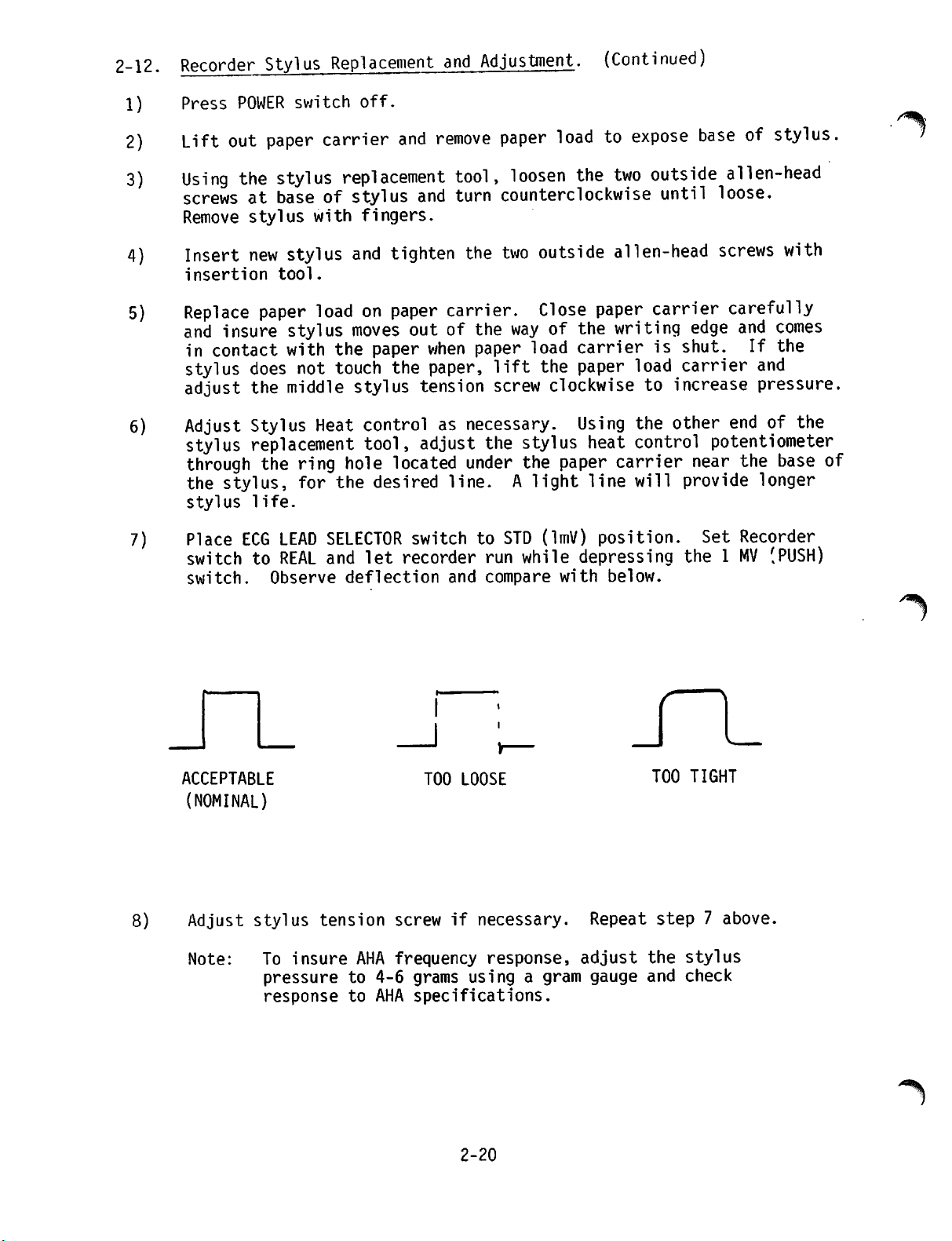
2-12.
Recorder
Stylus
Replacement
and
Adjustment.
(Continued)
1)
2)
3)
4)
5)
6)
7)
Press
Lift
Using
screwsatbaseofstylus
Remove
Insert
insertion tool.
Replace
and
in
stylus
adjust
Adjust
stylus
through
the
stylus
Place
switchtoREAL
switch.
POWER
out
paper
the
stylus
stylus
new
stylus
paper
insure
contact
stylus
with
does
the
middle
Stylus
replacement
the
stylus,
life.
ECG
LEAD
Observe
switch
off.
carrier
replacement
with
not
ring
for
fingers.
and
tighten
loadonpaper
moves
the
paper
touch
Heat
the
stylus
controlasnecessary.
tool,
hole
the
SELECTOR
and
deflection
located
desired
let
and
recorder
remove
and
paper
tool,
turn
loosen
counterclockwise
the
two
carrier.
outofthe
when
paper,
tension
adjust
way
paper
lift
screw
the
under
line.Alight
switchtoSTD
run
and
compare
loadtoexpose
the two
outside
Close
of
load
the
clockwisetoincrease
stylus
the
(lmV)
while
paper
the
carrierisshut.
paper
Using
heat
paper
line
position.
depressing
with
outside
until
alien-head
carrier
writing
load
the
control
carrier
will
below.
edge
carrier
other
near
provide
the1MV
baseofstylus.
alien-head
loose.
screws
carefully
endofthe
potentiometer
Set
with
and
comes
If
the
and
pressure.
the
base
longer
Recorder
(PUSH)
of
/^llkN
8)
ACCEPTABLE
(NOMINAL)
Adjust
Note:
stylus
To
tension
insure
pressure
response
AHA
to
to
4-6
AHA
TOO
LOOSE
screw
frequency
if
necessary.
response,
grams
specifications.
usingagram
2-20
Repeat
adjust
gauge
_r
TOO TIGHT
step7above,
the
stylus
and
check
'**%
Page 37

STYLUS
CONTROL
HEAT
FIGURE
2-6
STYLUS
REPLACEMENT
AND
ADJUSTMENT
STYLUS
OUTSIDE
HEAD
SCREWS
TENSION
ALLEN
SCREW
r
2-21
Jan
1979
Page 38
SECTION
III
0
3-1.
3-2. FUNCTIONAL
INTRODUCTION
This
section
or
first.
followed
The
view
diagrams
cussion,
reading
section
in
LIFEPAK6Cardioscope/Recorder
is
block
The
LIFEPAK6block
of
the
the
NOTE:
in
this
values)
This
a
different
In
any
would
change
tion at the rear of this
CIRCUIT
providesadetailed
divided
diagram
subsequent
by the DC
DESCRIPTION
system
of
the
to allow for
circuit
In
section
from
would
case,
carry
into
description
Defibrillator
diagrams
operation
major
rare
occur
the
circuits
examination
descriptions.
instances
may
the
configuration
only
revision
the
engineering
applicable
information
DESCRIPTION
descriptionofthe
three
parts
major
of
are
of
in,
the
differ
if
the
than
each
presentedbyCardioscope/Recorder
module.
Figures
terms
are
slightly
the
configuration
notedinthe
manual.
circuits
and
DC
Defibrillator
parts.
module
of
provided
of
the
in-text
that
PCB
board
one
schematicinSection
Change
A
brief
of
the
3-1
and
its
two
later,
circuits
schematics
(e.g.,
the
user
in
question
presented
and
Information
general
LIFEPAK6is
3-2
provide
modules.
in
from
provided
component
may
in
text.
interim
modules.
Schematic
the
detailed
two
levels
have.
was
6
Sec
contained
The
functional
presented
module
an
overall
dis
while
3-3.
Monitor
in
Figure
no-fade,
and
and
in
boards.
a
given
The
five-lead
seven
Module
3-1
(4)
deflection
displays.
Figure
3-1
They
function.
preamplifier
cableordefibrillator
combinations,
iousDCand
isolation
processing.
The
rate
display
ECG
for
zation
heart
between
board
size
each
pulses
rate
Circuits.
are
incorporatedinthe
recorder,
printed
The
numbers1through7assignedtoindividual
correspondtothe
therefore
board
prearnplifies
power-line-frequency
the
provides
The
(5)
display,
circuit
indicate
accepts
patient
ECG
final
monitor
boards,
module
(1)
preamplifier,
(6)
charger,
andinthe
numbersinthe
which
ECG
paddles,
the
board
signals
sums
signaltoreject
components,
and
subsequent
amplification,
from
control.Inaddition,itdetects
successive
for
defibrillator
alarm,
and
systole
heart
rate
event,
module
digital
generates
use,
outputs.
circuit
functions
(2)
and
(7)
power
front
above
contains
the
the
and
interposes
amplification
signal
the
cardioversion
and
produces
panel
listingofcircuit
the
patient,
cable
signals
common-mode,
calibration,
R-wave
systole
portrayed
rate,
(3).
supply
controls
blocks
circuitry
either
for
via
into
spur
electrical
and
signal
and
portionofthe
synchroni
sound,
3-1
Page 39

D/A
CONVERTER
I
VERT
AMPLIFIER
DEFLECTION
I
YOKE
(CRT)
VERT
(CRT)
HORIZONTAL
YOKE
MOTOR
PEN
RECORDER
STYLUS
PEN
DRIVE
MOTOR
PAPER
MEMORY
AMP
FINAL
2
BANDPASS
SIZE
ECG
&
AMPLIFIER
FREEZE
ECG
OUT
lmV
CAL
SWITCH
REAL TIME
DELAY TIME
R-WAVE
DETECTOR
*-*
RATE
DIGITAL
CIRCUITRY
HORIZONTAL
HORIZONTAL
SYSTOLE
'
I
AMP
DEFLECTION
RAMP
GENERATOR
ALARM
OSCILLATOR
SOUND
ALARMS
RATE
r
AMP
PEN
DEFLECTION
DEFIB
CONTROL
TO
CIRCUITRY
SYNC
AUDIO
TRANSDUCER
VOLUME
SYSTOLE
CONTROL
HEAT
CONTROL
STYLUS
VOLTAGE
FLYBACK
CIRCUITRY
HI
ANODE
CRT
BATTERY
INDICATOR
LOW
CONTROL
PAPER SPEED
POWER
SUPPLY
AC/DC
CONTROL
BATTERY
15V
LI 'J
CIRCUITRY
RELAY
BLOCK DIAGRAM CARDIOSCOPE/RECORDER
3-1.
FIGURE
PREAMP
ISOLATED
LEAD
SELECTOR
rr
CABLE
PATIENT
RATE
DISPLAY
DEFIB
PADDLES
ALARM
CONTROLS
RATE
CHARGE
BATTERY
CIRCUITRY
AC/DC
CONVERTER
BATTERY
CHARGING
INDICATOR
I
ro
Page 40

3-3.
Monitor
The
to
digital
memory
that
a
time
power
anode
The
recorder.
fier
no-fade
heating
Module
no-fade
store
readout
base
supply
voltages,
recorder
in
the
board.
and
Circuits
board
form,
representing
to
for
and
board
The
rate
recorder
samples
stores
analog
CRT
deflection
and
amplifies
signal
board,
The
(Continued).
the
ECG
successive
the
past5seconds
form,
display
amplification
is
recorder
paper
of
board
either
or
delayed,
constant
and
the
the
real-time,
board
at a
generatesahorizontal
ECG
highrate,
samples
readout5second
providesDCsupply
for
CRT
signal
obtained
in
addition
speed
in
deflection
obtained
drive.
converts
memory,
of
ECG
for
applicationtothe
from
the
controls
reads
waveform,
history.
voltages,
signals.
from
memory
each
out
converts
sweep
the
recorder
ramp
The
final
in
sample
the
as
CRT
ampli
the
stylus
Display
light
AC
line
it
when
3-4.
(
Defibrillator
a
control
andatransfer
load,aone-ampere
rillator
A
gross
following
picture
the
Dashed
housing
The
applicationsinthe
either
POWER
As
various
a
temporary
board
blink
power,
line
and
may
later
lines
those
charger
circuits
display
chargesabattery
power
Module
panel,ahigh-energy
relay
board
containing
abbreviated
paragraphsinconjunction
be
obtainedbystudying
descriptionofindividual
enclose
functions.
board
rectifiesACline
switch
one
result,
supply
depressiononthe
charger
voltages.Asanother
reset
controladigital
for
each
heart
is
unavailable,
Circuits.
for
discharge
hour
12-volt
the
control
outlineofmodule
+12
various
volt
blocks
output
defibrillator
powerorrelays
+12V
to
non-charge
passes
display
beat.
as
alternative
and
The defibrillator module
storage
of
battery,acharger,
with
that
The
monitors
capacitor
the
charged
circuitry.
functionsistracedinthe
Figure
diagraminassociation
circuit
to
portray
constitutes
module.
front
through
panel
To
the
sets
relay
result,
state.
of
heart
charger
energy
battery
and
capacitor,atest
and
3-2.
boards
the
the
and
circuit
DC
provide
battery
flipflopUlto
Kl,
charge
flipflopU4receives
rate
board
inductor,
A
supply
it,
rectifies
source,
status.
incorporates
the
main
more
their
complete
schematics.
boards
for
the
output.
thus
establishing
and
a
selects
paddles
defib
with
all
charger
Initial
go
on.
^
(f*
The
operator
of
its
operative
having
settings,
rotated
the
the
front
dump
comparator
panel
atorsinmonochipU4sensesafractionofthe
high-energy
the
voltage
ator
outputs
operator
transitionstocharge-up
circuit.
that
cyclically
permeance
storage
capacitor.
representing
will
activates
not
eitheroftwo
There,asa
gate-on
transformer
With
the
fractioning
less
than
the
desired
reset
charge
state,
flipflopU4to
charge
switches,
sendingaCD&RLI
result,anoscillator
and
gate-offapath
il.
WithDCcurrent,
ENERGY
voltage
and
SELECT
energy
establishedinthe
path
charge,
the two
non-charge.
the
charge
signaltothe
will
commence
through
the
drivenbythe
switchtoone
level
intact
compar
and
compar
When
the
flipflop
charge-up
oscillations
primaryofhigh-
+12
volts,
Page 41

ICUIT
CD
LI
INTERNAL
PADDLES
BOARD
& RLI
+12V
ENERGY
PADDLE
CONN
DEFIB
UP
CIRCUIT
H
U6,U3,Q1,T1
LIMIT
INTERLOCK .
CHARGE
ENERGY
(FRONT
1
L
SELECT
SWITCH
RESISTORS
PANEL)
500 J SW
ENERGY
RESISTOR
&
DIVIDE
DEFIB
CAP &
INDUCTOR
1
TRANSFER
RELAY
TRANSFER
RELAY
AMP
Q2
—z—
TRANSFER
O.S.
U4
1
ri-
PADDLE
DEFIB
MONITOR
INTER
CONNECT
PADDLE
CONN
PADDLES
TO
QUICKLOOK
SYNC
PADDLE
DISCHARGE
SWITCHES
CONN
I
INTERNAL
PADDLE
DISCHARGE
(FRONT
PREAMP
•
•
SW
PANEL)
"1
A2
±
DEFIB
CHARGER
DEFIB
CONSTANT
CURRENT
BATTERY
CHARGING
SOURCE
CHARGER
"1
I
I
(FRONT
rh
BATTERY
CHARGING
INDICATOR
(FRONT
PANEL)
PANEL)
- i
R
SYNC
CONTROL
& F/F
R
U2
±j
TEST
LOAD
INDICATOR
(TOP
COVER)
FIGURE 3-2. BLOCK
3-4/3-5
SYNC
_
D!F1?
INDICATOR
SWITCH
(FRONT
TEST
I 1
DIAGRAM
LOAD
PCB
DC DEFIBRILLATOR
PAN)
_
\
Page 42

0^
PADDLE
CHARGE
SWITCH
DEFIBRILLATOR
MAIN
READY
LIGHT
U
CHARGE
SWITCH
FRONT
READY
LIGHT
ON/OFF
RESET
AMP
U4
ON/OFF
SWITCH
FRONT
PANEL)
ON/OFF
INDICATOR
PANEL
PADDLE
CONN
J
500J CHARGE
•*+12V
READY
LIGHT
OSC
LAMP
DRIVERS
U2
ENABLE
U4
&
DUMP R
RELAY
DUMP
(PART
TRANSFER
RELAY)
F/F
Q U4 R
RELAY
OF
K
+7V
REF
U6
+5V
ORIGIN
BATTERY
INDICATOR
(FRONT
LEVEL
PANEL)
INDICATOR
CALIBRATION
CIRCUIT
R8, CR17
J
r
ON/OFF
RELAY
Ul
F/FQ
ON/OFF
RELAY
U5
AMP
+5V
n
SUPPLY
U6
E+12V
ON/OFF
RELAY
Kl
ORIGI
LINE
SWITCH-OVER
RELAY
^
12V 1AH
BATTERY
BATTERY
J
Page 43

3-4.
Defibrillator
Module
Circuits
(Continued).
3-5.
flowing
the
the
sensed
ator
charge
external
with
relay,
is
required
pulse
This
circuit
is
given
CARDIOSCOPE/RECORDER
The
scope/Recorder
starting
no-fade,
circuitry.
in
Tl
off
periods,
energy
output
the
simplified,
they
by
the
transitions,
flip
effecting
through
flop.
paddle
sync-defib
for
elements,
in
the
following
with
cardioscope
primary
high
representisstored
energy
discharge
capacitor
capacitor
the
defibrillator-monitor
introductory
and
detailed
paragraphs
circuit
the
preamplification
during
voltage
level
disabling
With
flip
chargeup
flop
logic
discussion.
3-6
description
and
recorder
the
on
periods,
pulses
comparator
switchesorthe
in
discharge.
discharge,
resume
are
in
the
reaches
further
completed,
U2
in
defib
In
namely
neglects
and
being
induced
capacitor.
chargeup
single
sync
interconnect.
in
the
desired
operator
internal-paddle
mode,
mode,
the
receipt
various
interrelationships.Amore
through
3-12
presented
circuitry
display,
provide
by
individual
and
rate
display
the
continuing
interrupted
Tl
secondary
When
by
actuation
enables
one
functional
the
level,
resetting
the
more
of a
condition
systole
complete
LIFEPAK6Cardio
function,
through
and
power
by
and
voltage
compar
the
of
both
switch,
transfer
sequences,
view
the
supply
3-6.
The
interconnecting
interconnection
Cardioscope/Recorder.
Preamplifier
selection,
ionofDC
A.
Input
electrodes
being
and
Buffers
individually
data
Board.
isolated
power
and
and the
channeledtothe
circuit
by
connector,
its
own
operational
Operatedatunity
andalow
All
fouropamps
output
characteristics
a
high-resolution
The
three
and
averagedbyresistors
and
appliedtothe
cancelling
the
preamplifier.
addition
a
summing
puts
buffered
signal
connected
array.
correspondingtovarious
wiring
for
The
diagram
the
sub-assemblies
preamplifier
in
preamplification,
line
frequencies.
Drive.
monitor
shielded.
preamplifier
Jl.
All
are made
Each
ECG
The
through
of
the
amplifier,
gain,
each
buffer
impedancetothe
being
closely
diagnostic
that
partofthe
match.
outputs
right
leg,
increases
The
arm
to
the
Various
This
application.
from
the
R13,
R14,
drives
the
and
left
Wilson
sum
resistance
fractions
lead
Section6provides
which
provides
common-mode
(See
connections
ECG
Figure
via
input
five-lead
four
four
physically
comprises
input
rejection,
3-3
from
of
input
1/4
buffering,
and
between
cable,
the
these
leads
of
presentsahigh
Wilson
same
arms
networkinthe
monolithic
isacritical
and
left
R15.
that
The
result,
member
common-mode
leg
buffered
network,
quad,
consideration
leg
withacommon-mode
rejection
outputs
constitute
combinations.
the
complete
the
LIFEPAK
lead
and
reject
3-4).
the
patient's
each
patient
leads
is
module
input
is
and
buffered
Ul.
impedance
next
stage.
their
are
summed
invertedinU2
ratio
are
in
which
the
provides
network
6
lead
in
of
out
3-6
Page 44

JPN
-a
avro—^
1
Rib T
-*—vvv-J
10K.,
I/4W,
6%
(whV"»
*
(rbcSJ—^
V W
(BWNj
7/"
,RZO
>IOK
l/4WS%
R'
.
IOM
—vw^fr
49.9K
.IOM
0
/ TO PINS 9,IO,M, OF
^ A
PINS
9.IO.II,OFU0(CD4OSb),/s«yX
TLO&4
1/4
>^»
1/4W5*
ul
>*♦
RI4
2TK
l/4W5*J
U<&
(C040S3YOK?
1
WILSON
RI71
-VW
NETWORK
RIBl
IOK> ,OK5
'££?
RI9
'£*£<
14
|IS'
ie
-8$—^
ir5
El:
U4
COAOSIB
7
'15
15,8
j&jr8
12.
•u6a
•
1/3
1
-8
CD40S3B
US
CD405JBJ
|4
L4^
—AA/V-
R4T
49/5K
•i<o
J
15
-S-8
a
I
IZ
ATE
I
ts&r-*3
ISOGNO—^
W
PAOOLE
(-)
PADDLE
^
f£
PfeT
HWV
2.M
J2.
1/401,5%
^
R24>2&OK
R66
CI4
.0O4lMf/50
R2fc<280K
5-7
Page 45

RZ7
-VNAr
20
255
K
u&a
4 1/3
C0405iB
•
T
is
!s.<o.a
ZfolK.
cn
PRE-AN
ORW£
3«g_
CR2D
k +IS LMVH>i./)Z.-8.0
♦IS
LMVH>L/)Z.-8.0
K
„ 1
—rr-*
TJ'-
LM52QI-AZ:o*i/w
^Ul5
ATE. 6
2*£<
C6
.2/SO
-S
CI3
2.2/SOV
37<?/»/>
-SYNC
L?"
03
r>>—G"°
'.£»
SYNC
l_i
I
I
."ES:
I.
I.
UNLESS
ALL
RESISTORS
ALL
CAPACITORS
3-?
OTHERWISE
AREINOHMS,
IN
SPECIFIED
MFD/WVDC.
1/8W,
1%,
<T
USC^7
FIGURE
3-3.
VSPI
liO
6>MD
800101
PREAMPLIFIER
BOARD
3-7/3-8
SCHEMATIC
Jan
19;
Page 46

3-6.
Preamplifier
B.
Lead
panel
1.
tion
Board
Selection.
determines
In
position
voltage
amplifier
control.
2.
Each
of
possible
3.
The
final
the
ECG
The
seven
diodes
codes
state
CRT-12.
is
applied
units
equivalent
connectionofeach
on
the
binary
signals
originatinginthe
available
(continued)
The
the
STD,
can
stage
the
next
lead
combinations.
switch
signal
different
In
as
U4
and
of a
multiposition
control
at
the
U4
setting
sources
of a
of
thereisno
then
through
seven
position
source.
lead
any
control
U5.
be
applied
actuationofanother
positions
selects
combinations
given
setting,aunique
input
Electrically,U4and
selector
appearsatits
input,
and
U5
any
V,
LL,
outputs.
nine-position
inputtothe
preamp
input.
independentlytoa
uniquely
the
defibrillator
are
switch-selected
to
pins
9,
switch.
pin
3.
Therefore,
of
seven
RA
combinationsofanalog
and
LA
leads
switch
on
preamplifier.
A 1
mv
standardiza
later
front
selects
panel
one
paddles
one
of
seven
10,
and
11
of
U5
are
The
each
output
the
depending
can
be
made
the
front
of
seven
as
through
binary
solid-
(I
Somewhat
and
the
return
solid state
not
at
position
an
8-volt
obtained
C.
Amplification.
cable,
the
amplifier
After
are
makes
especially
therefore
Overall
DC-reject
inputs
integrating
the
applied
for
to
basicallybythe
byafaster
constant set
arbitrarily,
U5
output
paths
are
completedtothe
switches
PADDLES.
control
from
signal
that
first
the
Whether
employs
stage
the
as
the
U6a&b,
potentialtoU6
defibrillation
obtained
is
applied
operational
of
inverselytodifference
AC
common-mode
high
closely
the
circuits
U2d,pin3.
because
three
circuit
the
matched
op
amps
feed
The
involving
back
valuesofR36
reacting
basically
circuit
by
U4
output
referenceorsignal
can
be
thought
return.
Instrumentation
provided
At
position
through
amplification,
rejection.
three
in
operating
provideanominal
through
the
PADDLES,
so
that
paddles.
from
the
U6a&b
amplifiers
the
amplifier
The
op
amps
characteristics.
U7 to
front
the
paddles
panel
the
Amplifier
to a
U2b,
signal
U2d,aprocess
rejection
are
monolithic
AC
gain
provide
feedbackisaccomplished
an
RC
time-constant
and
C4,
or
involving
R37
and
(for
U9,
C4.
largerDCswings)
Ql,
and
of
as
the
Signal
Amplifier
selector
selector
input
or
the
patient
differential
U2c
and
and
reference
efficiency
and
of
500.
DC-cancelling
either
determined
an
RC
via
time-
signal
and
via
is
connects
is
U2d.
that
is
an
The
normal
of
the
However,
defibrillation
the
output
speed
instantaneous
this
of
circuit
DC
DC
output
discharges
comparator
is
enabled
output
level
or
lead
U9
transitions
3-9
at
may
as
long
U2d
is
less
be
momentarily
selection
to a
as
the
than
exceeded
changes.
logic
absolute
3.2
volts.
In
that
high,
charging
Jan.
value
following
case,
1979
Page 47

3-6.
Preamplifier
Board
(continued)
LEAD
SELECT
SWITCH
PATIENT
CABLE
INPUT
PADDLES
INPUT
*\-
>r
BUFFERS
LEAD
SELECT
LOGIC
WILSON
NTK
60/50 Hz
NOTCH
INSTRUMENT
AMP
n a
CHOPPER
ISOLATOR
I
ISO
POWER
SUPPLY
ECG,
60V
P-P
FIGURE
C.
Amplification
up
C7,
conduct.
insertedinthe
The
resultant
restores
U9
output
instrumentation
Common-mode
R33
in the
With
is
conveyed
cable
amplifier.
response
3-4.
(continued)
and
thereby
Asaresult
quick-acting
U2c
outputtozero.
swings
rejectionismaximizedbyadjusting
DC-reject
input
through
In
is
from
PREAMPLIFIER
applyingahighto01
R37,
much
RC
circuit
and
inverse
With
low
again,
amplifier
circuit.
selected,
switch
that
case,
0.05-40
turning
to
normal
the
U6c
the
instrumentation
Hz.
3-10
BOARD,
lower
greatly
BLOCK DIAGRAM
that
in
resistance
reduces
feedback
causes
throughU7rapidly
zeroDCoutput
off
Ql
and
operation.
instrumentation
to
Q2,
the
inputtothe
amplifier
its
that
than
time
FET
R36,
constant.
re-established,
returning
potentiometer
amplifier
the
output
chopper
frequency
to
is
Page 48

/jlp\
3-6.
Preamplifier
c-
Amplification
In
contrast,
amplifier
paddles
through
decreasing
D-
more
as
effect
response
when
Notch
the
To
than
often
being
cable
Filter.
possibility
form
remove
switched
filter.
The
circuit
The
first
at
all
frequenciessothat
stages
the
Ull,
(the
filter,
and
European
inherent,
Following
than
notch
UlOd
outputisswitched
Board
output
selected,
U6c
tenfold.
encountered
limit
(continued)
(continued)
with
paddle
is
moreover,
to
R39.
the
normal
to
increase
to 1
input
exists
is
When
input
switched
the
This
Asaresult
with
Hz,
selected.
paddle
for
RC
time
the
as
an
places
paddle
opposed
input
artifact
ofacomponentatline
that
component,
through
op-amp
UlOc
U8a
employs
stage
filter
multiple
produce
operational
proper)
application).
even
the
if
circuit
filter
frequencytoits
the
and
appliedtoan
divides
the
will
feedback
sharp
band-rejectat60
Stabilityofthe
component
stages,
original
through
selected,
through
U2c
output
R39
constant
low-frequency
use
preamplifier
to the
is
selected
being
power
instrumentation
the
U8a to a
in
parallel
in
the
are
rejected,
low-end
0.05
present
frequency
active
amplifiers
the
input
reduced
not
saturate
circuits
inafixed
signal
involving
high
values
UlOd
restores
input
U8b
to
the
instrumentation
notch
pin
DC-reject
DC
for
amplifier
filter.
is
connected
with
variations
Hz
monitoring,
on
(50
R36,
the
frequency
low-end
the
or
circuit
accompanying
60
output
band-reject
U10a,b,c,&d,
proportion
to
the
next
that
Hz
UlOb,
(or
section.
high-gain
50
rejectionQis
drift
the
with
time.
signalatother
leveltoUlOa.
chopper
amplifier.
thereby
such
limit
ECG
in
Hz).
(notch)
and
three
In
Hz
for
The
With
a
is
Ull.
6
E.
Isolation
equipment
isolation
ineffectiveatECG
ontoamuch
carrier
The
main
and
T2
that
carrierisderived
power
the
gate
secondary,isalso
therefore
wave.
in
modulatedbythe
The
rate
in
for
The
Q2
at
Tl
outputishalf-wave
board.
effect
subsequent
Chopper.
power,
transformer.
To
the
preamplifier
signal
higher
is
supply
of
frequency,acarrier;itis
applied
and
conductedtothe
transistor
appliedtothe
gateonduring
preamplifier
20-kHz
frequency.
ECG
signal,istransformedbytransformer
Thereashunt
shortingitto
amplificaton.
further
However,
frequencies,
to
froma20-kHz
shield
output
inasmuch
the
transformer.
patient
the
and
is
passed
asatransformer
signalisfirst
the
square
wave
ECG
signal
through
signal-modulated
generatedinthe
primaryoftransformer
Q3.
The
20-kHz
gate
each
negative-going
outputisappliedatQ2
The
resulting
rectifiedbyQ3
capacitor
ground,
3-11 Jan. 1979
removes
while
wave,
of
Q2.
halfofthe
drain,
carrier,
and
conveyedtothe
the
detecting
reappearing
Both
transistors
and
amplitude-
20-kHz
the
ECG
from
an
is
modulated
T2
at
20-kHz
chopped
Tl.
component,
modulation
Page 49
3-6.
Preamplifier
F.
Isolated
addition
supply.Asthe
with
diodes
respecttoground,
CR18&21
Similarly,
provides-8volts
CMOS
ratings
Board
Power
(continued)
Supply.
servesasthe
opposite
to
regulator
CR19&20
for
are
not
The
20-kHz
isolated
endsofT2
they
are
connect
the
exceeded.
the
board.
outputoftransformerT2in
inputtothe
secondary
alternately
U12,
which
negative
The
regulators
preamplifier
swing
connected
provides+8volts.
swingstoU13,
ensure
power
positive
through
which
that
3-7.
Rate
Board
signal
R-waves
and
rate
of
the
Circuitry.
calibration,
and
generates
digital
rate
board
providesafull
A.
Bandpass
ECG
whose
to
ground,
blocks
the
signal
outputisUl,
the
providesamidband
the
preamplifier
from
generated
the
patient
Inasmuchasthe
amplitudeatUl,
the
circuits
voltage
simulating
produced
This
network
terminal,
equivalence
by
action
R2,
Ul,
The
rate
and
display
cardioversion
outputs.
showing
interface
schematicofthe
Final
Amplifier.
board
size
Figure
rate
provides
control.Inaddition,itdetects
sync,
3-5
with
On
systole
providesanoverall
other
board
the
circuitry.
rate
arrivingatPl-17isappliedtoa
pin
7.
CapacitorC2bypasses
thus
removing
DC
componentofthe
gainoftwo.
gain
byafactor
typical
inahuman
pin
are
operating
the
effect
pressing
connects
R6,afraction
pin
6.
them
from
input
of
approximately
of
1000
maximum
is1millivolt,
7,
can
of a
given
of a
the1mv
-12V
to
amplitude
be
expectedtobe1volt.
normally
CRT
1-mv
input
CAL
Jl-6.
of
this
the
signal.
This
gain
at
the
and/or
display,
to
button
By
-12V
input
500
Ula
typical
the
on
means
is
ECG
final
sound,
amplification,
rate
block
stages.
board
bandpass
signal.
The
actingincascade
raises
output.
of
the
Figure
the
preamplified
amplifier
25-kHz
harmonics
Capacitor
bandpass
the
ECG
ECG
signal
counterpart
To
to
calibrate
Ula,
the
of
applied
pin6input
preamplifier
front
potential
the
panel.
to the
alarm,
diagram
3-6
C3
amplifier
with
signal
verify
can
divider
inverting
that
be
The
result
Ula.
along
step
With
made,
equivalent to a 1-mv ECG
The
on the
(ring-tiporring-tip-sleeve)
service
full
normally
This
with
negative
circuit
the
output
Ula
isanegative
step,
the
displacement
normality
visual
of
Ula
main
flex
recording
output
equal
amplified
ECG
signal
step
is
connected
assembly.
or
other
or to
to the
step
and
(if
of
indicated
can
be
input.
There,
measurement
1/1000
ECG
input
3-12
of
of
one
volt
in
the
output
convertedinsucceeding
any)
will
the
display
and
used
asadeflection
via
depending
the
test
that
from
be
in
no
subsequent
Pl-8toa
signal,
purpose,
output,
the
patient.
evidencedbya
the
CRT
test
on
plug
used
is
the
latter
signal
stages
and
recorder.
gain
adjustments
reference
jack
and
insertion
for
field
equal
to
thus
Jan.
from
vertical
divider
the
being
(/^l
1979
Page 50

ERROR
INTEGRATOR
VALUE
CIRCUIT
ABSOLUTE
*
AGC
HOLD
SAMPLE
AND
SET
RESET
LATCH
K
INTEGRATOR
^h
CLOCK
COMPARATOR
RECORDER
FADE,
OUT)
(ECG
TO NO
OUT
IV/MV
ECG
BUFFER
AC COUPLED
SIZE
CONTROL
<-
*
-j
i
COUNTER
DIGIT
STROBE
BCD
RATE BOARD - BLOCK DIAGRAM
3-5.
FIGURE
j
CONTROL
VOLUME
DETECTOR
DURATION
*
*
IMV CAL
1
X2
GAIN
ECG
IN
IN
SIZE
PEAK
DETECTOR
DEFIB
LOADING
DETECTOR
LIMITS
ALARM
FADE)
NO
SYNC 4
INTERFACE
DEFIB/MONITOR
I
OJ
OJ
(TO
Page 51
3-7.
Rate
Board
A.
Bandpass
For
gain,
is
connectedtoPl-5.
dividerinthe
determines
Circuitry
the
(continued)
Final
Amplifier
(continued)
control,apotentiometer
In
conjunction
output
the
vertical
load
circuitofUla.
deflectionofthe
(ECG
size)onthe
with
front
R8,itformsapotential
The
pot
setting
CRT
and
recorder
panel
thus
displays.
Dependingonthat
of
Ul
outputisappliedtofinal
gainof6.
Outputofbuffer
corder.
peak
amplitudeofsignal
6 x
5/6x1000).
B
R-Wave
time
during
functionofthe
R-wave
reference
gain
stage,anAC-coupled
sistingofan
integrator,
That
AGC
amplification,
of
that
CapacitorC6couples
unity-gain
attenuate
P
andTwaves
availableattest
absolute
The
With
Detection.
monitoringofthe
peak
amplitude
level.
and
loop
stageiscontrolledbythe
buffer.
frequencies
detection
gain
setting,avariable
amplifier
fraction
Ulb
which
outputisconnectedtoPl-3assignal
U3aisusedasECG
the
Gain
Controlatits
ECG
OUTistypically5volts
R-wave
amplitude
patient.
R-wave
This
processing
and
reduceittoanessentially
automatic
buffer
absolute-value
circuit,
voltage-controlled
will
nowbeexamined.
appearsatop
amp
theACcomponentsofU2a
The
coupling
below
and
favoring
point3,enters
circuit,
about3Hz,
the
using
real
time
maximum
can
vary
Therefore
circuitsisto
gain
control
stage,
andafeedback
peak
detector,
resistance
The
ECG
U2a
input.
AGC-regulated
components
thus
R-wave
spectrum.
the
AGC
U2b
and
feedback
Uld.
signaltothe
(5/6)
substantially
the
sense
involvesavariable
network.
signal,
The
variable-gain
resistanceofQ8.
outputtoUlc,
(R23,
discriminating
C6)
The
(from0to
provides
ECG
setting,
(i.e.,
first
the
fixed
loop
error
after
selectively
buffer
loop
via
a
OUT.
re
the
with
major
ECG
con
final
a
against
output,
an
5/6)
That
circuit
regardlessoftrue
producesapositive-going
original
signalatTP3is+V,
conduct
ohmsasinverting
periences
Its
other
path
(-V),
shapes
through
appliedtoCR10
Rapid
the
time
referenceis-2V
and
thus
two
scaled
handifthe
for
whichitinvertstoproduce
inverted
U2b
provideapath
inputtoUld.
inputs:-Vthrough
signalatTP3is-V,
output.
appearatUl,
CR9tochargeupC13.
cathode,
variationsinabsolute
C13,
R34, R28,
periodispresentedtoU2casan
R29
maintainedatthe
ECG
ECG
polarity.
its
unity
outputistherefore
The
pin8as
C13
combination.
gain
inversioninU2b
for
applicationof-V
That
summing
summing
10K
ohm
-1(-Vx2
CR8
amplifier
output
positive-going
Because
+2.8V
charge-upislimitedto+2.8
ECG
signal
level
The
error
junctionofR30
3-14
waveformatUld
For
example,ifthe
causes
through
amplifier
and+Vthrough
+Vxl)=+V.
conducts,
thus
+V.
To
and
clipping
are
average
signal.
providing
has
but
restate,
are
conducted
voltage
integrated
value
overanRC
The
and
R29.
Jan.
output
CR7
thus
20K
one
all
volts.
error
1979
to
10K
ex
ohm.
On
the
no
input
wave
is
by
Page 52

3-7.
Rate
Board
B.
R-Wave
The
applied
resistance
For
error
negative,
integrating
Circuitry
Detection
error
to the
peak
detected
signal
(continued)
(continued)
signal
in
so that
capacitance
is
gate
proportion
voltages
to
U2c,
CR15
inverted
of
FET
to
pin
13
is
not
increases,
and
integrated
Q8,
in
signal
of
more
swings
conducting.
order
to
strength.
than
+2
positive,
and
AGC
at
U2,
vary
Q8
volts
and
Thus
damping
the
pin
14
and
drain-to-source
across
the
CI3,
output
effective
periods
lengthen.
the
C.
With
error
voltage
R
thus
to
minimum.
R-Wave
zero
signal
is
minimum.
maximum.
U2c
is
negative
been
brought
presence
tiation,
The
filtering
and
U3C.
passing
emphasizes
the
high-end
spectrum
Differentiation
stage
U3d,
instantaneous
relatively
while
noise
rejecting
or
ECG
signal,
reference
is
at
its
is
at
its
and
Detector.
to a
of
an
slope
function
Together
the
principal
the
roll-off.
and
effectively
with
slope
low
other
the
-2
maximum
The
gain
At
high
ECG
maximum
Q8
resistance
The
ECG
reference
R-wave.
magnitude
involves
they
R-wave
low
end
of
of
the
bandpassed
R25
and
of
the
frequency
the
high
artifacts.
steady-state
volts
plus
at
U2a,
signal
positive
signal,
This
detection,
is
level,
inversely
is
maximum.
level
process
two
applied
levels
level
its
by
AGC,
involves
and
op
provideapass
harmonic
the
spectrum
Stage
C8
U3c
provides
the
basic
wave.
favors
the
ECG
components
CapacitorC7serves
harmonicsofthe
frequency
spikes
CI3
voltage
to
U2c,
and
drain-source
proportional
such
that
(+0.5V),
Therefore
average
amplitudes
is
now
filtering,
duration
amp
stages
band
from5to
components.
and
effectively
the
high-end
low
roll-off.
waveshapes
sensing
differentiated
caused
is
zero,
the
Q8
gate
resistance
to
1+R,
the
error
the
Q8
gate
U2a
gain
having
examined
for
differen
detection.
employing
17
Hz,
Stage
is
U3b
provides
of
the
provided
the
to
pass
wave,
typically
the
is
signal
voltage
is
the
U3b
by
the
by
The
slope
configuration.
outputaslong
detector
Circuit
as
the
exceedsareference
volts
thereby
With
(slope=0).
are
resistance
(=
producing
when
an
the
slope
causes
the
unvarying
Under
maintained
-.6-(+.6)).
an
at
ladders.
output
input
-0.6
This
produces
outputatU2d
purposeisto
absolute
level.
of
the
amplitudeofthe
Specifically,
R-wave
outputofU3d
to
U3d,
this
of
condition,
and
+0.6V
The
difference
large
-12
volts.
3-15 Jan. 1979
input
inacomparator
produceasteady
differentiated
U2d
output
exceedsafixed
to
exceed
its
outputatpin
input
1.2
volts
16
pins12and
respectivelyby-12V
input
causes
is
the
then
op
-1.2
amp
amplifier
positive
goes
to
value
and
absolute.
is0volts
11
of
and
+12V
volts
to
saturate,
DC
signal
+12
U2d
Page 53
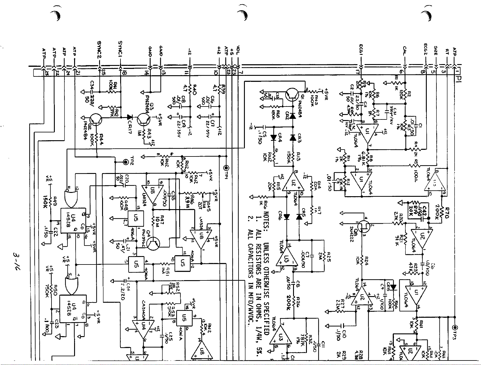
to -o
a
"0
T»
2
-o en r
,-JL
-1-
fro
CD
-*T\"S?-V'
<%y
O—'
Page 54
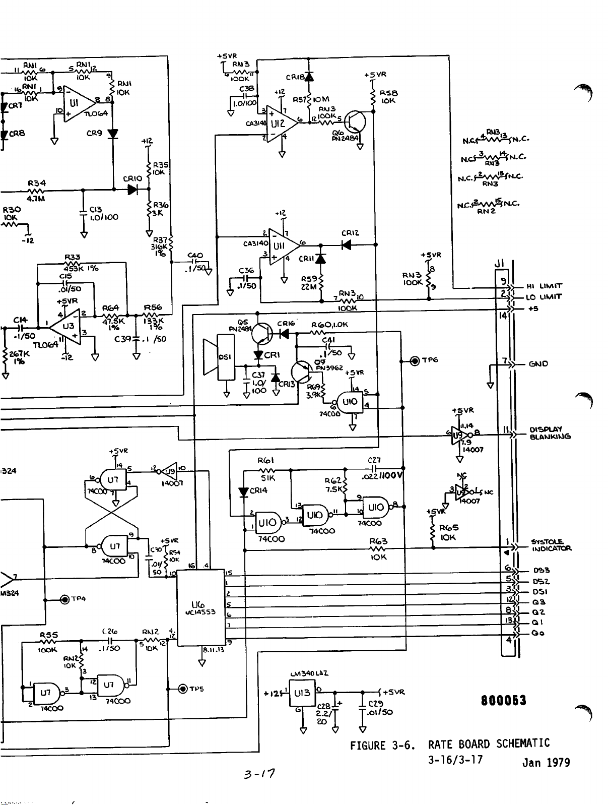
rcR8
R"2>0
IOK
AAA—I
upm
—w/y—
iok
-VNA/-
-12
4.1
Kb
+SVR
A58k
i
IOK 9I
CR9
^
yi
411
IOOK
+
5VR
H.CPVVV%N-C.
aCT2VNAv!%M.C.
•R35
,IOK
R<b4
1%
03^^.1
CRIO
R5«5>
/so
N£.*S^AA^N.C.
RN2
•If-
•I
If—|
IOOK.
Jl
-i£>—HI LIMIT
l}j—LO
14
LIMIT
+5
A
W\
J.D3
1.0/100
R33
—AAA/
CI5
OS
T
I
_C37
T '-O/
TCRI3"
RCol
AAA-
SIK
'CRI4
.
UlO)o^L__y
»—I
y
74COO
i4coo
RG>2<
7.SKJ
C21
.ozz/IOOV
74coo
uuzl
Rfc=>
-AAA^
IOK
«-®TP€>
tSVR
}>—
g>no
f
"^"^
^>
BLftKlKlKAGj
R(oS
:
IOK
^ SYSTOLE.
•?/—
INDICATOR.
%>_
D*2>*
-^4)1—osi
^Q3
-8£>—QZ
3-n
+
I2S-1
UI3
o
cz8l+
2.a/
eo
-(+SVR
1^
.Ol/SO
FIGURE
3-6.
RATE
BOARD
3-16/3-17
800053
SCHEMATIC
jan
^\
1979
Page 55

3-7.
Rate
C.
Board
R-Wave
Circuitry
Detector
(continued)
(continued)
JfF^
Duringarapidly
in
the
R-wave,
positive
(the
The
Finally,
millivolt,
responds
The circuit
12-volt
milliseconds.
With
is
initially
output
time
drops
charges
When
positive
or
constant
U2d
output
when
with a +12
output
-12V
output
becomes
constant
below
quickly
U2d
output
voltage
transistor
stitutingasignal
the
negative.
threshold
is
U3dabsolute
U2d
input
associated
of U2d
uncharged.
+12V
of
threshold,
through
has
to
conduct.
changing
U3d
ECG
output
When
it
across
then
zero
(+.6-(+.6)).
output
difference
volt
output.
with
has
transistor
lasted
(indicating
When
and
C5
charges
this
transmitted
path
U2d
been
that a
is
output
CR4,
positive
Asaresult
valid
input
will
to
equal
is
+1.2V,
CR5
accounting
exceeds
goes
the
requisite
positive
waves!ope
ECG
slope
through
20
ms.
When
reverts
the
RC
of
for
almost
via
CR2
to
Ql,
R-wave
U3d,
or
U2d
1.2V
Ql
senses
less
exceeds
CR3
the
to
that
the
pin
has
been
such
exceed
input
for
by more
and the
whether a
minimum
than
threshold,
and
slope
-12V
path
20
ms,
base
16
goes
sensed.
as
experienced
1.2V,
becomes
the
either
+0.6V
0.6V
than
comparator
drop).
a
positive
of 20
threshold),
U2d
R13.
and
being1ms.
of
The
eventually
C5
dis
the
increasingly
Ql
causes
low,
this
C5
RC
that
con
w|P\
Quick
once
D.
Cardioversion Sync
output
multivibrator.
stable
(+5
shutoff
U2d
from
condition,
and0volts)
single-shot
which
One
drives
and
the
lator
with Q2
swings
PI-25,
it will
result
the
monitor
defibrillator
has
base
high.
as
addition,
version
discharge.
of
Ql
is
reverts
Ql
to
negative
Generation.
is
inputted
Up to
that
with
respectively.
transitions
sustain
is
thatQbecomesalow
base
of
modules
for the
Q2
low.
interfaced
panel,aconstant
been
supplying
driven
That
signal
in
the
low by
high
SYNC
to
defibrillator,
effected
at
by
C33
discharge
output.
An affirmative R-wave detection
U4a
asalogic
time,
the
flip
flop
itsQandQterminals
Now,
to
its
unstable,
next
Up
to
and
with
10
during
that
the
pin
complementary
milliseconds.
that
moment,
SYNC
current
conduction
Q,
02
is
conducted
generate
current
switches
to
an
R-wave
the
SYNC
off and
the
signal
through
low
to
that
has
been
high
and
low-
11
pulsed
condition,
10
ms.
with
the
pushbutton
source
to
no-fade
marker
Q2
in
via
its
board
on
the
Pl-18.
collector
the
enablesacardio
R68,
one-shot
in
its
low,
It
the
thus
defibrillator
actuated
on
defibril
Now,
through
CRT.
In
3-18 Jan. 1979
Page 56
3-7.
Rate
Board
E.
Rate
an
belowinconjunction
As
Figure
U4b,
175
conducted
systole
the
result,
approximates
The
Circuitry
Measurement.
R-wave
soonasU4a
involve
3-7(b)
drives
milliseconds,
that
through
LEDtolight
U10,
pin8,audio
the
audio
thatofthe
feedback
loopofQ
servestoprevent
output
refractory
from
period.
retriggering
(continued)
The
further
rate
sensing
with
has
transitionedtoits
itsQoutput
the
hightoa
unittoits
Figure
Jl-1
3-7(c).
andonto
for
that
alarm
alarm
sounds
heart.
output
any
new
(and
the10ms
consequencesofthe
and
display.
pulse
diagramsofFigure
10ms
second
unstable
175
oscillator
stage,
The
resultingQoutput
the
display
ms.
The
for
They
unstable
one-shot
whose
boardtocause
sameQlow
that
withaninterrupted
high
from
U4btothe
presumably
single-shot
spurious)
during
detection
are
discussed
3-7.
state,
of
multivibrator,
duration
low
is
is
the
enables
interval.Asa
beep
whose
period
inputofU4a
R-wave
detector
the
175-ms
(>%
During
shot
returnedtohigh,apositive
the
previous
had
revertedtoits
heartbeat
period,
stable
condition,
pulse
about2ms,asdeterminedbyR48,
connecting
After
to
the2ms
start
current
C21
has
Figure
current
produced
that
gatetoconnect
on
C21
ratio
10-ms
shorted
a
new
C24,
Figure
lengthoftime
recent
measureofthe
effectofC24
successive
average
U5a,
pin1to
period,
rechargingata
through
since
3-7(d).
excursiontothe
a Q
transistor
then
been
That
output
ground
the
steady
climbing
climb
unstable
hightoU5b.
C24inparallel
and
C24
then
rapidly
equals
state,
the
capacitance
the
U5b
connection
temporarilytoground
C21
recharge
3-7(e)
detected
heartbeatsissuggestedinFigure
short
cycle
servesasa
between
R-wave.
current
sampling
term
the
rateatwhich
and
variations
will
Thus
and
U5a
gate
rate
Q4.
Asaresult,
essentially
reachesastateinwhich
ratio.
will
through
start.
stored
previous
the
storageofC21
yet
just
after
and
through
C20)
draining
has
C20
enabled
off
reopened,
determinedbythe
the
steadily
with
stopped
state,
This
voltage
react
the
10-ms
control
with
C21.
At
the
end
open,
detected
the
C21
U5a,
pins
Meanwhile,
sample
proportionaltothe
R-wave
across
heartisbeating.
charge
3-8.
quicklytosustained
the
10-ms
with
had
switch
U4a-Q
briefly
U5a,
single
having
chargeonC21.
allowing
constant
voltage
time,asin
across
when,inits
single
signal
The
of
will
1 &
the
again
2,
and
C24isan
buildups
It
shot
causes
charges
the
charge
me
current
be
and
voltage
the
during
serves
(for
thus
C21
^
< 1
then
across
most-
inverse
The
to
changes.
In
the
first
experienced.
voltage
the
end
C21
and
initial
it
is
seen
staircasedtoa
level.
halfofthe
During
across
of
thatonC24isdistributedtoC24.
chargeonC24isassumed
C21)
each
ramp,
that
withinafew
virtually
mock
each
history
heartbeat
illustrated,a60-BPM
period,
therefore,
V21
rate
(the
is
rampstoapproximately1volt.Atessentially
the
difference
heartbeats
stable
3-19
between
zero.
level,
the
charge
For
simplicity,
Eveninthis
the
voltage
asymptotic
with
on
worst
across
the
Jan.
the
case,
C24
C21
1979
has
**%
Page 57
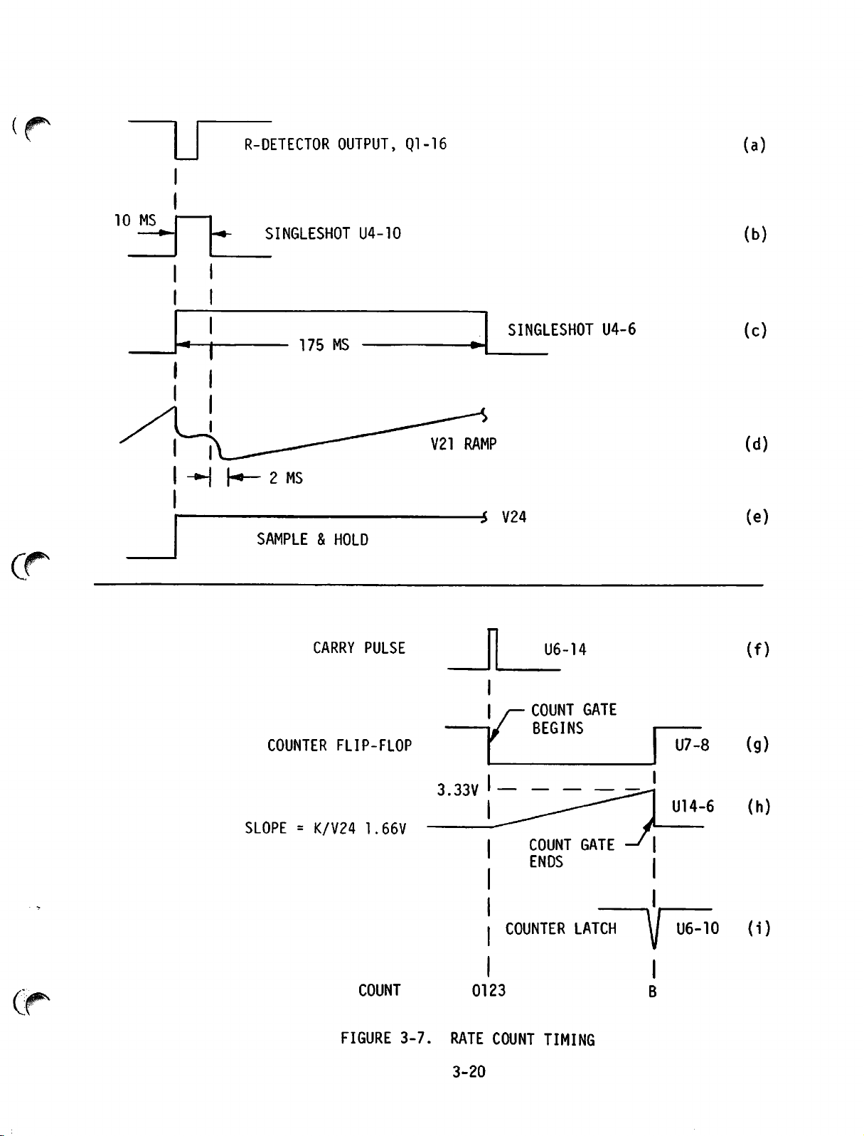
10
MS
R-DETECTOR
SINGLESHOT
OUTPUT,
U4-10
Ql-16
(a)
(b)
-H
h*—2MS
SAMPLE&HOLD
COUNTER
175
CARRY
MS
PULSE
FLIP-FLOP
V21
RAMP
-i
SINGLESHOT
V24
I/—
f
COUNT
BEGINS
U6-14
U4-6
GATE
U7-8
(c)
(d)
(e)
(f)
(9)
Ci
SLOPE = K/V24 1.66V
COUNT
FIGURE
3-7.
3.33V
COUNT
ENDS
COUNTER
0123
RATE COUNT TIMING
3-20
GATE
LATCH
I
\/
V
U14-6
U6-10
(h)
(i)
Page 58

3-7.
Rate
E.
Board
Rate
Measurement
In
the
the
end
Circuitry
second
of
each
equilibriumisquickly
change
quick
F.
Rate
voltage
ators.
this
the
steady
The
C24
Reference
from
60
reactionofthe
Alarm
(Systole
appearing
These
voltage,iswithinaselected
BPfl
value
audio
signal
comparators
voltageisappliedtothe
voltage
inputsbyconnecting
selectable
resistance
display
resistancestoground.
values
board.
(continued)
(continued)
half
of
ramp,
to
120
Sound).
across
determine
is
too
high
to
employ
levels
Jl-2
by
means
the
history,
charge
flows
attained.
BPM,
the
C24
weighted
C24
whether
be
sampling
One
is
or
too
appliedtoa
difference
inverting
are
established
and
Jl-9
of
two
120
BPM
from
C24
At
the
time
voltage
technique
use
of
the
as
an
inputtorate
the
heart
rangeofbeats
low,
rate,
the
comparators
loudspeaker,
amplifiers
inputofboth
for
respectively
The
operator
nine-position
is
assumed.
to
C21.
of
the
step
illustrates
weighted
as evidenced by
Ull
and
the
non-inverting
through
selects
switches
Now
But
again
radical
employed.
average
alarm
per
DS1.
compar
minute.
cause
U12.
units.
operator-
these
on
at
the
If
a
The
the
If
the
C24
voltage
the
high
heart
to
U12,
tion
signal,
The
base
DS1.
the
collectorofQ9
(QRS
systole
output
full
CR18
alarm
too
Q6.The
non-inverting
alarm
varies
CR11
reference
rate
alarm
pin3(high
from
one's
level
appliedtoU10,
resulting
of
transistor
During
2KHz
2KHz
non-alarm
signalisalso
is
VOL)
on
the
volume.
goes
volume
high
alarm
providesahysteresis
has
been
sustained.
low,
U12,
pin
resulting
input
output,
slightly
offers
evenifthe
around
similar
sample
appliedtoUll
appliedtoUll,
limit)
rate
(+5
or
is
limit),
volts)
pin2,enables
square
Q5,
waveisapplied
which
provides
conditions,
applied
connected
front
panel,
During
causingQ9to
beep.
6,comparator
current
slightly,
the
hysteresis
through
alarm
effect
With
through
actual
high
and
U12
is
pin3(correspondingtoa
lower
thus
conditions
tendingtostabilize
than
the
collectorofQ6
to
zero's
systole
through
providing
turn
off,
for
the
signal
output
CR18
C24
limit.
for
the
the
low
reference
level.
the
systole
the
through
drive
R60
current
beeping
U10
to
baseofQ9.
Pl-7toa
(U10,
thus
comparator
switchestohigh,
and
sample
In
low
shunting
variable
pin5low)
providingacontinuous
U12
voltage
R57
raises
magnitude
comparator
limit.
higher
than
low
applied
will
This
sound
(U10,
transi
alarm
oscillator.
and
CR16tothe
for
the
pin5high),
speaker
The
audio
control
U10,
control
of
the
pin
afterahigh-rate
at
U12,
the
pin
2
turning
the
original
on
comparator
subsequently
Ull,
diode
6
3-21 Jan. 1979
Page 59

3-7.
Rate
Board
Circuitry
(continued)
60
BPM
FIGURE
G.
Rate
servestoinversely
accumulating
The
The
cycle
are
is
counting
to
given
3-8.
BEAT
Display.
clock
count
counter
producedbya
U7,
is
ending
pin
11.
thus
countsincontinuous
with
from0to
the
first
R-wave
zero
has
As
PERIOD
its
SENSING,
second
control
countsina
made
to
measure
resettozero.
free-running
The
clock
1000
count
been
frequencyis285
thus
reset
detected,
mustbeconstrainedtolatchinthe
instant
count
seconds,t,is
is
to
(i.e.
such
equals
that
the
the
heart
adjusted
be
proportionaltothe
t=k/V24).
The
numberofmilliseconds
rateinBPM.
during
rationale
SAMPLING
function,
the
durationofa
three-digit
the
cycles
The
square-wave
takes
heart
clock
3.5
AND
the
voltage
binary
from0to
generator
seconds.
experiencedbythe
the
output
registerofthe
accumulating
That
calibration
gating
againstaknown
reciprocalofthe
for
that
equation
120
BPM
WEIGHTED
gating
rate
in
pulses
Hz.
counter
countatan
elapsed
periodinmilli
voltage
follows:
AVERAGE
across
period
counter,
BPM.
1,000,
being
Each
with
counted
whose
cycle
Subsequent
after
since
across
C24
for
U6.
each
output
of
a
counter
zero
BPM
and
C24
3-22
Page 60

fD
3
3
o
-s
rt
o
-s
rt
4s»
O
Cl
-s
CD
o
O
CD
to
fD
XJ
ro
-p»
-f>
ro
o>o
-H
_i.
«
fD
fD
_j.
rt
3-
s
to
fD
-s
CD
<
Cl
fD
O
CO
TO
rt
CD
CD
TO
CD
ro
ro
-O
C
o
rt
fD
Cl
c
fD
ZT
fD
JO
fD
fD
CD
-s
XJ
to
to
o
fD
fD C
CT
-S
rt
3"
fD
fD
rt
CT
O-
o
CD
fD
3
fD
3
-5
rt
T
O
al
ri
n
3
Q.
CD
tO
• 3
rt
CD «•
rt
O
CD O
rttQ
O
to
CD
to
O
< >
-••
cr
cr
cd
O CD
tO
rt
TJ3-C+
O
CL
xj
o 3
Q—•
cr
-s
3*
C
rt
CD
3"
ro
CD
-1.
co
3
-a
3
fD
—'"O
to
O
3
--J-O
3
rt
3"
cn
3"
CD CD O
fD O
—j.
-«•
o o
II
11
-p»
to
3
TO
Js>
-H
—'CO
"5
O
CD
3-
tO
CD
—1
CD O -••
fD
rt
fD
-••
3
Cl
o%
-H
ro
fD
rt
CD
CD
<
fD
to
to
CO
3 C
'-v
fD
3
O
fD
-1.
o
rfO
ro
cn
-»
co
cr
—'
O
fD
to
<<3"
rt
fD O
-s
3--0
CD
3"
rt
to
3
-J'
fD
< fD
-O
O
3 ?
rt
_j.
O
c+
O 3 3 c
to
S-o
vj
3*«
CD
3 3
to
Cl
CO
~5
fD
Cl
3"
O
3
O
3 O
-i.
CT
3 fD ~
fD
to
o.
"5
_j.
-"•
rt
CO
rt
3
3" 3"
-s
<= fD
fD
rt
fD
ZT
ro
CO
fD
CD
c
o
rt
_i.
vj
cr-a
-a
rt«
n>
rt rt
3
O
rt
CD
3 O
CL
cn
CD
fD
to
CO
3 C
-J«
3
->•
-».
rt
CD
-t
fD
fD
fD
3
<
< O
Cl
fD
—'
3
Cl
O
_i.
*>Q
-5
-h
D"
3 3
3
to
O
rt
r+
to
» O
fD
-»•
-S
rt
<
3"3
rt
rt
O
3
-••
rt
fD
7TXJ
Cl-
XJ
CO
fD «•
C+XJ
CO
3 3 C
CLtO
CD CD
XJ
3
fD
CT
3
C
—'
CD
CT
3 fD
-•.
O"
<
CO
fD
3"
CL
rt
O
o
tO
-s
-s
—*xj
3 fD
o
-••
CD
ro
3
fD
rt
fD 3
3
to
c+
3
-s
to
onto
-s
o.
. 3 cu
CD • CD
CO
c+
to
-s
r+
to
CD
fD
-5
CD
3
-J.
tQ
fD
vj
3"
CT
rt
fD
C
_j.
-n
-j
-l.CQ
rt
to
to
cr
cn
CO
rt
fD *»
to
O 1
T3
fD
r+
fD
to
3"
tQ
O
3T
CD 3
CXX)
cn
cr
cl
-%
OJ
cd <<
-s
rt
U3
O
to
CD
rt
3"
"^
-^
cr»
cn
—«
•
-h
->•
-S
Cl
-••
to
o
->
rt
-»
O
-a
CD
O
rt
c
-Pi
—'
O
C
-1.
-S
rt
tQ
fD
ft
3*
3 •
(+T
-
rt
OJ
cn
COJ
"O
CD
=T
-S
O
to
CD
c+
tQ
-*•
3*
rt
3
rt
O
fD
fD
Cl
-S
rt
<
fD
<
o
-J.
rt
_).
3
rt
fD fD
CO
CD
fD 3
Cl
—I.
to
3
3
to
I CD
—1.
(-*•
CL
-i.
to
3
O
-h
CO
fD <
3"*<
fD
_i.
Cl
»
CO
XJ
fD
fD
-s
CO
_l.
a>
~n
_ -J
cr
—iCQ
3
Q)
fD
—»
Cl
1 « c
—1 o
_i.
vl
< fD -
O O
C_j.
CO
r+
X3
3
-*•
"S
fD
-"•
3-
3
-J-
3"
rt
vj
«
CD w
•a
fD
fD
—'
'<
-S
CD
3
—'
CD C
-J.
to
CL
o o cr>
cd
—-h
to
fD
sz
rt
-s
fD
3"
to
<-t
rt
ro
cn
to
O
C
rt
C
o
XJ
co
rt
—*
rt
O
-s
rt
—'<<
rt-o
O
3
fD
Cl
c
rt
to
•
'
o
to
—'
rt
O
to
< a
Cl
r+
O
C
c+
O fD
C
C+
T3
fD
—1
C
—J.
3 <-h
C+
CD (/>
tO
—"to
3"
id
CO
<X> -
to
v. CO
fD
—•
-"•
co-o
-s
_i.-a
O
O 3
fD
cr
3
CD
CD
cz
cr»
cr
fD o
rt rt
fD
zr
-s
-s
O
3"
rt
to
rt
3"
rt
rt
3
co
rt
3 O
CD
I
O
fD
fD
to
-S
o 3
3 O
fD O
CD -+»
O 3
fD
-s
CD
-h
--J
co
3'
XJ
fD
fD
-J
<
-s
o«
-o
rt
o
fD £
fD
-S
<<
fD
-j.
-s
ZTXJ
rt
to
fD
-S
-1
Q_
O
rt
CM
rt
O
O
rfO
O
to
•
ri-
to
cr
-"•
to
-h
fD
O <
I
-h
ro
o«
rt
C
-a
c o
CO
-s
CD CD
O
3"
Qt
-s
00
—•
fD
T3
rt
rt
-S
fD
7T
CD
-j.
—1
fD
—•
o
en
TCTft
td
rt
O
to
-ps>
->•
3
rt
O O
TO
rt
CD
fD
to
CO
CD
O
CD
« fD
T3
fD
-s
I N
-fi
—'
-a
—i
3 •
r+
O
o
-a
fD
to
—'
o
to
7T
O
CT
CD
fD
-+>
r+
3
CD
CO
3 ~S
-S
-J.
CD fD
<<
to
ro
3=>
fD fD
Cl
fD
fD
O-
3"
rt
rt
-•
to
3
xj
fD
fD
<
rt
o
-a
3
3
cr
C
3"
rt
fD
-S
3
cr
3
C fD
fD
rt
CD
-s
rt
fD
3
CD
3"
—i
_J.
3"
rt
O
to
rt
_l.
to
-a
fD
Q.
rt
3
o o
3
o
o
ro
«s= fD
3
CD
3-
CD
O
"5
tQ
-J'
fD
fD
< 3
—'-a
—'
rt
O
3
rt
CD
O
to
O CD
-ti
CD
-s
o
fD
ZT
rt
CO
en
.
X
co
3
CD
o
X
fD
cr>
I
fD
fD
—'
3"
to
CD <
O O
-*.T3
3"
3"
CD
to
3"
P2
2
O
«
—j.
O
rl-
to
1
-h
O
-a
•a
<-+
to
I
O-
Cl
O
•^J fD
U3
«
« O
4*.
CD
w 0>
C
o
cr»
sl3
« CD fD
to
—'
rt
CD
fD
-j
_i.
_i.
to
Cl
to
to
N
-P»rt
fD
en
rt
3
to
fD
—•
to
O
3-
l
XI
CO
fD
rt
to
CD
fD
-5
CD
fD
I
fD
3
CO CD
XJ
O
3
cr
co
3
ro
ota
ro
<
-j.
T3
fD
fD
3"
rt-
C
rt-
to
CT
>»
fD
O
fD
to
CL
CT>
—'
CD
fD
Cl
-J.
O
*•%
CD
XJ
XJ
o
o
• o
fD
fD
to
-s
rt
-h
o
—'
cr
CD
rt
-h
to
co
<
-j.
rt
cn
CD c
4^
cd
cn
3
fD
X
o
CO
cd
vlct
cr
fD
zr«
3"
c+
O fD
1
CD
to
CD
fD
3
'
3
3
S
-«•
3 fD
-
XJ
-j.
rt
O 3
cn
cr
O
—'
—1
-"•
—\
ro
.
cn
O
rt-
CTXJ
3
o
-s
—•
rt
to
o
fD
Cl
Cl
3
n TO o
Cl
3
rt
O
fD
CO
Cl
3
CO
CO
00
cr
v
—J.
«
-a
3
-j.
-a
-s
CD
rt
o
CD
o
en
3
cr
cr
-P.
—'
£
tQ
3 •
3
.C*
1
-<•
rt
CO
cn
o
C
•a
CO
3
O •
T3
3
CO
3
to
« o
00
rt
CD
3-
« —I O —>
s:
ZO
OS
ro
fD
rt
CD
to
fD
ro
<
+
ro
cn
TO
rt
CO
I
—'•
vj
•
CL
vo
—1
^ CD
O 3
3
—i.
-i.
O 3
rt
3
3
CD
_i.-o
tQ
--•
to
I
E 3
—•
3
fD fD O
fD
3
3
rf
3"
r+
-
-S
-h
v.
fD 3 CD
to
3"
O O
•H
O
in
fD
r+
3
C
c+
-j.
Cl
-».
O
fD
_j.
-h
3
3-
rt
3
rt
3
3
3"
C CD
rt
3"
3 fD Gi
-J.
rt
fD
n
c
o
3"
CL
ro
rt
-s
cr
C
to
3
-»•
1 <*
_j.
to
Cl
fD
-h
3-
c+
r+
fD
fD
—'
c+
-*•
fD
rt
to
O
to
rt
3"
CD
ri
-
rt
to
ft
3
-j.
tO
fD
XJ
fD
to
7T
CD
-s
—•
CD
<< C+
fD
—»
(/)
c
XJ
__i
to
c
XJ
fD
o
-s
-«•
00
CLtQ
3
CD
to
fD
C
-s
CD
CO
3
rt
_j.
O
fDtofD
-S
XJ
CD
rt
CD
-J«
O
CO
O
'-h
3
fD
CD
3-
-h
rt
O
fD
-*•
<
—J
.£»
CT
fD
O » 3
CO
fD
rt-
fD C
rt^
Cl
to
c+
C
->.-a
Cl
CD O
—'
Cl
3"
fD
-S
fD
< fD
S
c+
3
3
o
O
3-
o
I CD
' 3
• 3
fD
CD
-*•
o
Cl
en
• 3
CT>
« fD
00
fD o
-a
rt
-i.-O
-••
to
cnta
Cl
o
fD
CD fD
<<
-a
I
ro
CO
Page 61

3-7.
Rate
G.
Board
Rate
Circuitry
Display
(Continued)
(Continued)
3-8.
With
the
no
blanks
sounds
placement
systole
the
BPM
if a
low
Regardlessofcause,
until
current
R45,
been
has
by
emitter-base
U8
U8
U9,
board,
it
its
which
finally
through
R46,
3.33
likewise
the
swings
goes
the
volts.
voltage
towards0volts.
high
pin8and
where
constitutesacontrol
terminal
condition
comparator)toexceed
inverting
No-Fade
ECG
signal
(a)
convert
number,
samples
periods,
convert
the
vertical
voltage
time
base
Board
(b)
similarly
(c)
them
which,
input.
Circuitry.
every
the
signal
store
extract
in
succession
amplifierofthe
applied
for
display
being
digital
alarm
of
the
sensed,
display.
is
patient
the
the
voltage
Q4.
Up
voltage
been
at
junction
causing
is
it
extinguishes
11
to
causes
at
At
the
3.33
04
volts.
emitter
and
two
transmittedasa
terminal
the
any
The
Ull
The
5.125
milliseconds
smplitude
that
obtained
number
and
alternate
to
to
the
of the
an
output
Concurrently,
set.
The
cause
lead
selectortothe
effectisto
across
till
op
amp
it
then,
inverting
blocks
becauseofthe
non-inverting
The
U8,
minus
R4
at
When
things
the
/*-
2.7V.
it
to
happen.
reaches
low
the
digital
signal
10.
to
This
U5d,
inverting
selectable
output
no-fade
inasolid-state
stored
numbers
analog
CRT,
CRT
analog
goes
circuits
and
duringagiven
in
evidenceatthat
during
from
voltage
and
(d)
horizontal
output.
is
producedatJl-11
the
rate
of no
systole
STD
prolong
the
further
chargingofC21
collector
ohmic
input
input,
pin8output
voltage
Now,
through
display
causing
path
inputatUll
reference
low
and
U8,
pin9has
U8,
pin
has
drop
through
however,
1.66
volts,
One,
charges
it
Jl-11
of
that
is
to
heart
C24
(the
voltageatthe
actuates
sample
the
gate
sample
moment
memory
the
memory
form
along
1023
preceding
sequentially
for
application
generateasawtooth
amplifier,
will
which
alarm
input
may be
position.
drop
10,
the
been
through
voltage
set
the
pin
8 of
pin1of
inverted
the
display
rate.
to
connect
to
3.33
low
rate
non-
the
alarm.
amplified
period:
toabinary
with
1023
sampling
and
to
ramp
create
at
Two,
volts,
alarm
a
The
for
no-fade
every
action
fourth
sample.
approximately50Hz.
is
made
5.12
to
say,
a
time
zontal
exhibits
In
order
events,
addressing
up
of
1024
ms
duration,
if
fully
it
traced
starting5seconds
sweep
rate
any
fading.
that
referred
the
rate
is
display
to
and
arises
adjoining
as
follows:
It,
Inasmuch
segments,
The
therefore,
as
the
reconsistuted
each
horizontal
hasarepetition
sweep
ECG
representingasample
portraysahistoryofabout5seconds.
on
the
ago
up
sufficiently
may
showareal-time
the
constantly
sampling
rate
CRT,
it
would
to
the
fast
that
updated
normally
3-24 Jan. 1979
show
present
instant.
none
of
progression
present
differbyone
heart
this5sec.
instant,
is
rate
analog
That
activity
The
hori
of
ECG
the
part
in
gated
of
signal
of
is
from
interval
memory
1024.
Page 62

3-8.
No-Fade
Asaresult,
the
levelofthe
the
segments.
waveformsonthe
appear
waveforms
CRT,
left
off
Board
Circuitry
the
namely
ECG
and
successively
The
screen,
on the
(continued)
analog
the
signal,
collective
screen
their
right.
segment
segment
is,
replacedonthe
resultofsuch
are
place
displayedonthe
representing
as
time
progresses,
seen
to
move
being
takenbyprogressive
righthand
the
present
shifted
rightbymore
lateral
to
the
steppingisthat
left
side
instantaneous
stepwise
up-to-date
of
to
all
until
they
more
dis
recent
f^l
Actuatinganoperator
lateral
sampling
addressing
remains
occurs.
A
supplementary
vertical
that
causes
uniformityofthe
circuit
R-wave
The
Figures
tional
to
A.
movementofthe
rateby1
partin1025,
ratestoequalize.
selected,noupdateormotionofthe
circuitonthe
movementofthe
the
vertical
display
movement
intensification,
visual
introducesavertical
portionsofthe
no-fade
3-9
circuit
and
3-10.
functions
groupingsofcircuit
in
text,
AnalogtoDigital
in
into
instantaneous
ference
Converter.
derived
are
initial-capitalized.
levelinthe
no-fade
boardassignal
amplitudeisto
amplifier
The
as
discussed
preamplifier
other
control
CRT
labeled
display.
causing
Thereafter,
no-fade
CRT
display-painting
exceedsareference
thereby
trace
displayed
with
markerata
waveform.
are
The
dashed
elements.
Conversion.
and
ECG
Ul3
inacomparator
inputtoU13
in
the
following
FREEZE,
It
board
providing
minimum
discussedinconjunction
blocksinFigure
The
The
ECG
amplifier
IN.
be
evaluated,itis
isareference
however,
does
so
by
dropping
the
sampling
while
the
original
senses
beam.
level,
the
To
for
power
pre-selected
expenditure.
3-9
block
signal,
There,asthe
titles,
having
stages,ischanneled
circuitinthe
paragraph.
halts
and
memory
FREEZE
CRT
mode
display
effective
the
degree
the
circuit
overall
pointonthe
with
enclose
v/hen
been
waveform
appliedtodif
Analog/Digital
staircase
the
the
ECG
Another
func-
referred
raised
whose
voltage
"^
'
A
400-kHz
after
servestoclock
one
the
the
other
U5b.
binary
locationofone
Access
oscillator
inversionina
Address
the
The
Address
numbers
Memory
Counter
sampling
from1through
consistingoftwo
parallel,Uland
Counter
appearingasa
numbers8through
the
outputsaset
A/D
Converter.
high
providesamaster
Schmidt
two
free-running
consistingofmodules
Cycle
Counter
word
U2.
at
2047
outputsaconstantly
to
be
written
Duringanormal
of
numbers
U5b-Q4.
are
appliedtoresistance
3-25
trigger,
Counter
1024,
4-bit
U9b
three-module
consistingofU6a,
each
into
1024-word
sampling
from1through
The8most
square
in
Chip
U6b,
number
or
read
significant
wave
output
Select
synchronous
U7a,
and
U5a,
cycling
set
specifying
out
fromaRandom
RAM
modules
period
2050,
the
with
bits
network
Jan.
which,
Logic,
counters:
U7b;
and
of
the
in
Cycle
2048
of
RN1
in
1979
^^
'^)
Page 63

J|P\
PKEtee
6ND
OCivE
ECO
SYNC
MORI2
in——$>
11
(f2V
——»
-?*
Page 64

-3-2-7
SCHE
BOARD
800159
MFD/WVDC.
OHMS,
IN
3-26/3-27
NO-FADE
5%,
ALL
FIGURE
2.
3-9.
CAPACITORS
1/4W,
ALL RESISTORS ARE IN
UNLESS OTHERWISE SPECIFIED
AND
FI|_TER
D/A
VERTICAL
a* ^
?•<
^—vw-,
\ -
14-
1(0
14
Ifo
\<b
\<o
7
—
S
7
fo,e.
—
Ife
14
14
14
14
\(o
\to
IO
8
7
7
7
7
&
8
e
8
II
+ *3
(.iMO
LM320WP-5
LM34<XA£E
40G8
TL084
MO*«74
40lf>
4003J3
CA3I30
4CM7
4081b
4071b
74CI4
4013
-
tAU4'}tfJ
407ec
4I04A
TYPE
U2I
•J
9
1
U2.3
U22
U«^,U20
Ulfc,UI 7
ui5,uie
LH4
uie>
U1Z
Ull
UtO
ue>
U7
ue
US
U3,U4
UI,UZ
DES
1
SS COUNTER
Page 65
3-8.
No-Fade
A.
Circuitry
AnalogtoDigital
(continued)
Conversion
(continued)
(T
When
B.
the
resulting
increasestoa
the
U13
output
increasing
successively
output
inversioninU9c,alogic1appearsatpins9of
abling
sequent
1
to
2050.
numbers
shifted
goes
low,
further
higher
The
andU4correspondstothe
digital
pulses
been
lasted
Write-In
number
conversion
countedbythe
2050
and
2050/4x105
to
Memory.
2050,
the
Logicgohigh.
which,
of
the
Hence
to
of
the
ending.
chip
channeledtopinsRin
that
countertozero,
same
logic1from
theQoutputofU8
the
RAM.
The
theQoutput
data
latchedinU3
The
select
pulse.
actual
voltage
level
equaling
switches
being
into
however,sodoes
inputtothose
number
digital
for
the
clock
staircase
that
from
hightolow.
generatedinthe
registersU3and
gate
unitssothat
during
the
Cycle
the
restofthe
word
(i.e.,
analog
ECG
present
Counterinthe
frequency
400
output
of
number)
IN
sampleiscomplete.
seconds,or5.125
When
counter
Asaresult,
simultaneous
the
cycle
outputstoUlOb
AND
gate
the
ready
Ullb
goes
for
servesasa
high,
write
counter
cycle
the
constitutingawrite
signal
fromU8servestorelease
and
U4
RAM
write-in
during
the
occursasa
the
UlOa
kHz,
millisec.
Ullb
from
ECG
Up
sample
U4.
RN1
IN
signaltoU13,
to
that
counter
As
soonasU13
output.
U3
they
registernosub
current
thus
signal
sample
the
tally
and
and
sample
Ullb
latched
the
period
mounts
in
producesalogic
counter,
next
1-2050
Set
input
complementinthe
for
sampling
initiate
cycle.
into
write-intothe
period
resultofthe
to
U13
instant,
have
After
and
cycle
U4,
output
dis
from
into
analog-to-
The
clock
having
event
Read/Write
has
to
1
resetting
Meanwhile
flip-flop
command
just
upcoming
the
been
U3
U8.
form
RAM
In
ordertosave
that
of
the
clock
power,
(200
accomplishedinUlla
an
input
from
200
Ql,
whose
clock
caused
to
Read,
during
from
the
least
kHz
pulse
resultant
inputtoU8
one
word
allowing
the
next
the
400-kHz
significant
outputismultiple
so
to
the
enabled
the
chip
kHzasopposedto400
in
the
master
bit
select
Chip
Select
oscillator
portofthe
purpose:
output
that
be
written
enables
after
full
sampling
3-28 Jan. 1979
theU8Write
into
1024-word
period.
the
one
pulse
frequencyishalf
kHz).
Logic.
anda200-kHz
Address
(a)itgates
RAM's,
(b)itprovides
output
address
RAM
contentstobe
The
This
Counter.
the
command
halving
gate
AND's
input
transistor
command
reverts
read
is
The
a
has
out
Page 66

3-8.
No-Fade
C
Circuitry
Full
Memory
capacityof1024
occurring
tationofthat
involved.
(Continued)
Time
overaperiodof5.248
Representation.
words
represents
seconds.
5.248
seconds
promotes
Writinginof
the
recordingofECG
understandingofthe
the
The
following
RAM's
events
compu-
full
,
i^
circuits
Each
the
Thereforeasample
accepting
D.
"
sampling
cycle
counter.
1024
period
Read-Out
RAM
Counter,
thus
of:
1024x2.05/400
From
lodginginthe
the
becomingaRead
periodinthe
event
Memory.
Write
A/D
1024isgenerated
resultofa
rate
the
RAMat200
RAM
are
in
the
the
registersbya
coincident
U9b
For
counter
Meanwhileasdiscussed
sequenced
RAM
Output
with
each
summedinresistance
Converter.
successive
channeled
Circuit
the
vertical
After
voltage
throughagate
and
sent
amplifierofthe
involves
Each
takes
such
samples.
sec.=5.248
the
count
2050/400,000
Thusafull
Afteragiven
address
signal
signal
most
fromU8invertsasexplained
for
Converter.
sequentiallyinthe
receiptof2048
kHz
rate.
out
Latch.
pulse
the
trailing
word
latched,
smoothingina
steps
Therefore
into
the
Each
appliedtotheir
edgeofthe
the
network
RN2inthe
(analog
(discussed
off-boardasa
accumulationof2050
takes
one
sec.
sec.
clock
The
RAM
representsatime
period,
RAM
binary
fills
sampleiswritten-intothe
recently
the
durationofthe
During
clock
earlier
during
storage
wordissuccessively
outputsofU15
filter
segment)
later)inthe
signal
CRT.
generatedinthe
next
that
period
Address
Counter,asthe
the
full
pulses,at400
theQloutputisenabling
the
next
registers
period,
U15
and
latched
clock
chip
Vertical
stage
are
inputs,
select
and
pulse
U16
Deflection
there,
sequentially
the
Intensity
ECG
OUT
for
application
ones
1/400,000
upon
on
sec.
Address
earlier,
sampling
cycle
kHz
of
clock
the
Ulb
into
arriving
from
are
then
D/A
1024
Control
to
^%
E
ECG
Freeze.
'
(a)
that
address
(b)
that
the
right
from
righttoleft.
These
to
2050
cycle,
In
the
successive
events.
completed
counter
Three
each
new
previously
the
newest
hand
results
clock
which
Fiqure
edgeofthe
occur
periodstoaccomplish,asopposedtoa
takes
3-10,
voltage
The
abcissa
after
has
2050
cycled
facts
sample
heldbythe
are
written
sample
read
CRT;
clarifiedbyFigure
into
oldest
out
from
and
(c)
becauseasampling
2048
clock
the
sawteeth
ramps
denotes
clock
from1to
3-29
periods.
represent
outofRN1,
time
from
counts.Inthat
1024
and
the
RAM
occupiesamemory
stored
sampleofthe
the
RAMisdisplayed
the
displayed
takesatime
the
generationofthree
and
therefore
t(0).
The
time
backto1.
3-10,
namely:
ECG;
on
ECG
moves
interval
RAM
three
first
the
ramp
RAM
Accordingly
equal
read-out
sampling
is
address
when
Page 67

j0^\
3-8.
No-Fade
E-
ECG
sample1is
as
reflects
to
appears
In
address
the
prior
left
new
the
left.
counts
appears
selected
for
oldest
Board
Freeze
Circuitry
(continued)
written
the
CRT
horizontal
2050
right
sawtooth
sweep.
initially
two,
counter
word
sample
formerly
sample,
edge
of
two
immediately
And
so
earlier
on
the
at the
the
newest
digital
clock
Accordingly
on the
sample
reaches
stored
which
the
CRT
will
preceding
with
time
per
sweep
extreme
end
digital
word.
(continued)
in
to
the
RAM
sweep
counts,
is
each
when
righthand
in
two,
count
read
is
two.
at
address2and
cycle2was
(actually
be
displayed
sample
each
given
cycle,
left
edge
of
the
next
word,
which
it
lodgesinaddress
initiated
sawtooth
sample
edge
written
when
also
one
of the
into
New
sample2therefore
representing
displayed
offscreen).
on
the
extreme
will
have
address
each
sample
of
the
sampling
thus
CRT.
period
takes
the
represents
is
CRT.
the
During
moved
being
moves
That
the
1.
RN1
output
displayed
RAM
when
the
on
the
read
right
as
one
read
left
address
the
place
edge,
slot
out
until
repository
Inasmuch
one
it
the
erases
oldest
extreme
period
and
to
the
two
it
then
of the
left
3
clock
is
(T
The
leftward
resultant
can be
panel.
the
read/write
number
signal
while
cycle
no new
sweep
matching
remains
F.
Circuit
board
(U9a)
Adjustment
G.
Defibrillation
mode
sync
SYNC.
superimposed
pulse
and
enabled.
movement
disappearance
prevented
This
2048
to
the
counter
information
period
Adjustments.
is
action
AND
the
FREEZE
now
the
RAM
fixed
provided
RAM
count
in
logic.
gate
switch
reflecting
readout
location
of
by
pressing
channelsalogic1input
Thus
Ullb
and
resetting
in1clock
is
written
The
by an
andatime-constant
is
selected
pulses,
Board
was
generated,
of the R2
Sync
each
circuits
on the
potentiometer
Display.
and the
pulse
then
ECG
thus
the
ECG
offscreen
the
at a
has
two
the
remains
cycle
and
main
oscillator
actuated,
step
in
2048
period,
shape.
clock
circuit
When
R-wave
is
at
indicating
detector
channeled
cause
points
display
left
FREEZE
can
after
button
be
some
to
cycle
or
clock
counter
high
inputs,
cycle
from1clock
displayed,
frequency
comprised
counter.
both
pulse
the
selected
periods
of a
composedofRl,
trims
the
an
corresponding
the
frequency
synchronized
produces
to
the
no-fade
intensified
when
defibrillation
halted
on the
OR
output
initiatingawrite
and
five
seconds
control
gate
UlOb
representing
its
in
Consequently,
the
address
pulse
and
with
and
ECG
for
the
Schmidt
R2,
and
defibrillation
defibrillation
board
spike
to
marker to be
each
and the
through
the
horizontal
exactly
display
no-fade
trigger
Cl.
to 400
as
signal
timeasync
was
suitable
2048,
kHz.
3-30
Page 68

3-8.
No-Fade
G.
Board
Defibrillation
Circuitry
Sync
(continued)
Display
(continued)
o
«*
WRITE
CLOCK
v..
NEW
SAMPLE
WORD
1
1
SAMPLE
WRITE2—i
2050
2
NEW 1
^.-
SAMPLE
,'".
v„<
WRITE
3
V
3
rNEW
1
OLD
READING
SWEEP
s
1024
1
1
FIGURE
Initiating
to OR
suchamarker,
gate
UlOa
appearinginthe
durationofthe
accept
Cycle
(representing
an
uninterrupted
Counter
until
decimal
\
OLD
SWEEP
CRT
3-10.
in
the
comparator
SYNC
pulse.
register
numbers16through
OLD
1024-
2
2
DISPLAY
CARDIOSCOPE
the
SYNC
A/D
converter.
input
Thus
to
registers
V OLD 1024
X0LD
(CRT)
pulse(alogic
Asaresult
UlOa
progressionofbinary
capacity
is
reached,
2048).
3
SWEEP
DISPLAY
is
overridden
U3
and
numbers
3
high)
any
U4
are
from
namely
is
low
for
forced
255
NEW
2
inputted
the
to
the
counts
r\
3-31
Page 69

3-8.
Mo-Fade
G.
Board
Defibrillation
Circuitry
Sync
(continued)
Display
(continued)
Consequently,
next
chip
memory
latch
enable
and
read-out
all-one's
producesaU21
circuit
SYNC
all
to
the top
vertical
Intensity
uniformity
is
reduced
readout
further
direct
As
discussed
for
causes
That
to
Q2,
switches
anode
then
pulse
ones
during
blip.
cycles
pov/er
proportion
three
blanking
is
to
is
+12
circuit.
period.
of
Control.
of
by
samples
say,
invertedasa
v/hen
the
pulse
output
high
causes
that
the
screen.
waveform
blanking
from
savings
to
earlier,
out of
of
beam
the
volts
to
This
current
arrives,
into
latches
to
AND
signal
intensification
The
readoutofapparent
pulse,
This
circuit
to
the
The
ECG
the
U15
gate
the
CRT
combined
saves
brightness.
CRT
the
RAM
are
the
the
intensity
gating
low
J1-J5,
shuts
anode
promoted
speed
50
four.
off
off
voltage
memory.
of
Hz
signal
In
while
signal,
to
Q3
as
output
the
sampling
eight-bit
and
Ul6
U21
in
the
Intensity
of the
trace
is
effect
beam
In
part,
during
Brightness
by
varying
trace
vertical
to
U14a
addition,
the
appearing
base,
causingQ3conduction
signal
beam
accelerating
period
ends
number
is
all
ones.
Sync
Control
CRT
ECG
Detection
circuit.
beam
throughout
amplitude
concurrently
isabrightened
power
the
and
power
three
uniformity
beam
intensity
travel.
blocks
channeled
ECG
output
as an
INTENS
and
the
written
into
The
Gate
being
deflected
enforces
requirement
of
every
and
in
ECG
output
to
Q2,
is
blocked.
input
to the CRT
high
voltage.
That
the
four
it
that
On the
is
controlling
tiating
amplifiers
slope
U19c.
rectification
This
of
the R wave
intensity
burning
Delayed
time
is
When
of
receivesapulse
U8
being
other
gated
on,
hand,
the
display
the
signal
U20a
at
U19d,
The
output,
of
produces
the
ECG,
the
increased
particularlysoon
portion.
is
needed,
baseline
Record.
to
record
erased,aDelay
during
32,
terminal
causes
read
any
registers
from
during
slope
intensity.
in
andband
pin
7.
signal
the
slope
In
reducing
into
In
order
from
memory
Record
sampling
R2
of
from
U17
memory.
the
one
read-out
of
the
ECG
signal
The
slope
C12
and
processing
U19d
to
produce
That
flip-flop
the
signal
INTENS,
of
intensity
consequence,arelatively
the
CRT.
to
give
an
Circuit
period
counter.
and
U18
This
word
is
inverted
isanegative-going
the
vertical
on the
the
steepest
power
requirement
the
operator
interesting
is
provided.
the
cycle
U8
in
the
The
to
latch
is
thus
in
serves
is
the
an
deflection
faster
ECG
counter
delay
resulting
the
applied
four
as the
sensed
result
absolute
and
traveling
slopes,
low average
and
adequate
before
reachesacount
record
Q output
binary
when ECG OUT
basis
by
differen
in
operational
value
amplified
for
of
at
full-wave
signal.
portions
experienced
the
chance
reaction
that
waveform
circuit
from
word then
as a
binary
the
on
beam
of
3-32
Page 70

3-8.
No-Fade
I.
Delayed
Board
Circuitry
Record
(continued)
(continued)
f^k
number
form,
normally
recorder
delay
Each
to
and
mechanism.
ramp
produced
sample
a
and
For
start
to
64
come
therefore
period
then
simplicity,
at
1.
During
and
constituting
from
sample
inserted
ramp
through
address
word
1.
will
newest
resistance
filtered
conducting
as
signal
corresponds
byacycle
the
memory
back
to the
1.
Therefore
that
address
periods
into
address
Similarly,
1024,
33
back
will
represent
sample,
and
FREEZE
DELAYED
counter
takes
is
in
sketched
ramp,
the
32.
earlier
during
to
be
conveyed
the
which
network
amplified.
to
gate
RECORD.
an
ECG
RN3,
count
2050/400,000
serially
original
ramp1the
it
sequences
the
word
first
This
address
than
the
1 at the
ramp
1.
At
clock
to
sample
will
be
lodged
summed
It
is
U14c
and
Figure
A/D
converter
from1through
sec=5.125
scanned
address.
from1through
read-out
sample
input
representsasample
present
end
of the
2,
the
count
the
recorder.
taken
993
in
there
then
outputted
3-10
through
address
from
to the
sample,
period
address
64,
samples
address
to
analog
conveyed
to the
illustrates
sampling
2050.
ms.
its
scan
1024,
RAM
recorder
which
occupied
will
the
word
As in
earlier
2.
through
staircase
Each
During
1024
is
assumed
at
clock
taken
will
cycle
stored
ramp
than
voltage
the
such
addresses
to
then
back
count
will
993
be
by
from
1,
2
at
this
the
Thus
the
occurred
J.
5.09
Blanking
sweeps
A
seconds.
is
effected
Intensity
200
Hz
divide-by-four
applied
the
Horizontal
conducted
oscilloscope.
the
analog
conducted
oscilloscope.
K.
Horizontal
to
generate
operation
2050
pulses
5.125miHi
to 5
volts
buffering
U19b
output
to
recorder
993 x
Control.
is
gated
in
Control
square-v/ave
constantly
5.125
the
ms
In
to the CRT
Output
Circuit.
from
counter
through
through
through
(freeze
amplifier
yieldasawtooth
is
gated
Sweep
The
gate
Sweep
the
from
sec.
DC.
OR
gate
Circuit.
U14b
Ul2,
U14a.
U14a
Circuit.
horizontal
mode
the
400-kHz
The
ramp
This
input
U19a,
through
senses
earlier,
order to
deflection
Gate
the
Cycle
U12.
to
UlOc
Jl,
The
to
pin
pin2output
Asaresult
to
Jl,
pin
The
sweep.
not
selected)
clock,
voltage
to
the
summed
swing
U14b.
3-33
that
save
Logic,
Ul2,
control
One
sweep
22
one
21
ramp
Inasmuch
over
Sweep
with
from
and
records
is
to
say,
power,
only one of
amplifiers.
Horizontal
Counter
is
pin2output
the
analog
out
as
signal
is
also
ECG
sample
as
signal
from
the
as
builds
the
-2.5
+2.5
overacount
normal
that
time
Circuit
volts
to
-2.5
the event that
the delay
This
Sweep
inputted
Circuit
(50
gate
of
four
H0RIZ
applied
is
to
to
out of
ECG
OUT to the
A/D
converter
the
ramp
sweep
period
swings
is
applied
and
inverted
volts.
is
every
blanking
to
the
Hz)
is
U14b
thereby
the
control
four
is
in
normal
from0to
is
from
to
This
four
and
in
is
used
0
in
Page 71

3-9.
Recorder
circuits
Board
for
Circuitry.
stylus
heating,
The
pen
recorder
drive,
board
and
contains
paper
drive.
the
control
xjjp*
Heating
is
provided
is
effected
U3
timer
Upon
voltage
period,
to
timer
Q2
base,
through
When
Thereafter
the
of
resistor
The
of
circuit.
recorder
that
therefore,
U3,
it
P2-3
Cll
is
U3,
timer
U3.
duration
pin3cyclic
0.11
msec
The
paper
recorder
6-volt
The
fractionofthat
at
25
amplifier
to
the
emitter
constant
minimum.
drive
paper
drop
mm/sec.
Q3
armature
counteracts
voltage
the
recorder
by
the
by
the
turn-on,
turns
pin
4,
turns
fully
that
for
an
charged,
pin3output
The
R27.
of
U3,
high
circuit
at a
across
The
to
supply
winding.
across
stylus,
current
single
on
Ql
pulse
current
Ql.
collector
reappears
transistor
output
Charging
required
from
circuit
charging
Cll
voltage
without
on,
delay
conducting
uninterrupted3seconds
Ql
duty
cycle
It
varies
pin3cyclic
is
adjustable
turns
alternates
(U3,
from
off
pin3output
about
low
is
(via
R27)
producesasteadyDCcurrent
fixed
itself
inverted
motor
speed
so
voltage
constant
Negative
frictional
the
of
that
tapped
output
drive
motor
25
mm/sec.
its
anode
by
at
Ul,
current
feedback
or
winding
for
the
heat-sensitive
P2-3.
associated
Cll
takes
is
and
high
Control
with
developsaQl
about3seconds.
low.
and
That
at
U3,
stylus
for
quick
Ql
collector
low
pin
low)
47%
(R27=0)toabout
0.104
from
msec.
0.45
Zener
is
regulated
potentiometer
pin
10
analog
through
to
Ul,
pin
inertial
inductance.
variations
of
that
Ql
low,
3.
heating
initial
goes
under
depends
The
duration
msec
maximum
that
CR1
maintains
to
R20
fixes
controls
the
12
paper,
output
and
by
the
base-to-emitter
For
that
transmitted
Applied
to
current
warmup.
the
19%
fixed
command
on
high.
of
the
setting
(R27=50K).
of
U3,
to
advances
the
a
-6
volts.
the
speed
power
motor
and
commutator
from
by
maintaining
Q3
3-10.
The
ECG
cation
fier
mounted
input
stages
line.
applied
or
right
pen
deflection
signal,
and
application
on a
to
the
depending
either
provide
Op
amp
heat
sink
two
velocity
overshoot.Abridge
feedback
the
former
representation,
Rate
lighted
also
Four-bit
are
channeled
decoder
respectively.
signal
lead
stage
Display
digital
providesablink
binary
Ul.
Ul
is
involving
the
Board
display
coded-decimal
through
These
Transistor
low
inputted
selector is
placed
real
time
to
the
pen
high-frequency
U2
furnishes
to
dissipate
pen
deflection
on
the
signal
and
sendsafeedback
circuit
balanced
primarily
latter
Circuitry.
of
indication
including
via
adjustment
primarily
The
patient
numbers
Jl
to
pins
four
pins
correspondtodecimal
supply
through
on
pin4of
STD.
or
delayed,
deflection
discrimination
the
power
thermal
windings
polarity.
the
potentiometric
damping.
circuit
heart
synchronous
generated
7,
1,2and
appears
motor.
against
amplification
energy.
in
series,
The
small
signal
main
to
windings,
pickoffs
for
fidelity
of
Figure
rate
in
beats
with each
in
the
6 of
BCD-to-seven
at
The
The
for
third
U2
of
3-12
per
beat.
R-wave
Jl-6
first
and
drive
numbers
voltageisinputtedatUl,
Ul
blanks
the
display
for
amplifi
two
ampli
noise
as
output
on
such
the
deflection
winding
to
damp
Rll
at
square-wave
provides
and
R10
inertial
R10,
and
a
minute.
count
segment
1,
2,4and
pin
16.
when
the
is
is
left
senses
and
R17,
It
circuit
8
A
patient
3-34
Page 72

r
n,
II A
"»
II 3
^
C2.00a7/50V
C4
Cl .O22./50V
-i>
.OOl/SOV
II-
Ji
-ffiZV
-H2V
-CMC
-4
-*;
'few
nC
NC
PENJ
MOTOR
DRIVE
CIRCUITRY
12V
— i17
.001/SOV
IMS
-IZV
STYLUS
HEAT
CIRCUITRY
3-
^t>
Page 73
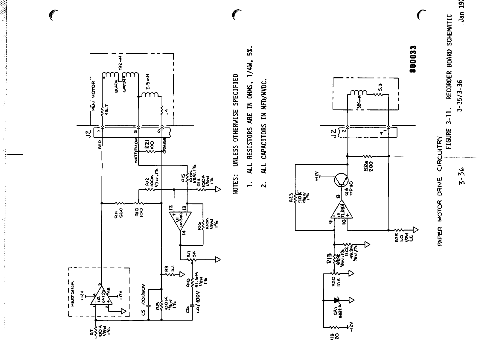
5%.
/*%
SCHEMATIC
1/4W,
OHMS,
SPECIFIED
OTHERWISE
UNLESS
ALL RESISTORS ARE IN
1.
NOTES:
MFD/WVDC.
ALL CAPACITORS IN
2.
800033
BOARD
RECORDER
3-35/3-36
3-11.
FIGURE
i
CIRCUITRY
3-36.
DRIVE
MOTOR
WK
SI
MEAT
U9
CPU
20
PAPER
IK182I4
-\IV
Page 74

3-10.
Rate
Display
Board
Circuitry
(continued)
G
|J—L
-Sn.c.
The
decoder
combinations,
range0through
series
diodes,
resistor
one each in
EachDSmodule
arrangedasone
cathodes
3
to
connectedtoa
connected
base,
segment,aspartofa
the
that
of
emitter
transistor
FIGURE
outputs
each
9.
contains
segmentofa
all
seven
Ul
LED
emits
3-12. DISPLAY
through
combination
A
high
in
RNl
and
DSl,
pins
atagiven
thence
DS2 and
seven
LED's
of a
transistor.
output
conductsbyvirtue
light.
displayofsome
are
high,
BOARD
9-15.
representingadifferent
pin
to
the
DS3.
such
LED's,
seven-segment
connected
When
and
when
The
result
SCHEMATIC
These
anodes
pins
is
transmitted
of
with
each_LED
figure
through
the
anode
simultaneously
ofapulse
is
the
display
integerinthe
go
high
in
digit
through
three
light-emitting
spatially
y
array.
module
of a
at
pins
given
its
the
of
LED
cathode-
transistor
that
range0through
800161
ten
in
the
a
The
14,
is
one
9.
TransistorQ4controls
plays
playedinthe
place.
digitsinthe
ten's
unit's
place,
the
lightingofLED
place.
SimilarlyQ3controls
whileQ2controls
3-37
segmentsinDS3,
DS2
DSl
digitsinthe
Jan.
which
dis
digits
hundred's
1979
dis
Page 75

3-10.
Rate
Display
The
three
strobe
digital
strobe
any
inputs
rate
pulses
given
next7ms,
enabled
digits
illuminated.
for
selected
Board
transistors,
circuits
transistor
during
3.5
at
on
Jll,
any
ms
for
Circuitry
which
each.
display
Q2,
J10 and
on the
one
line
is
enabled
time
(continued)
Q3,
and Q4 are
J9.
rate
is
10.5
for
the
other
Eye
persistance
inagiven
The
board.
ms.
3.5
turned
strobe
The
The
ms,
then
tv/o
transistors
of
vision
readout
on successively by
signals
period
strobe
to
originate
betv/een
duty
disabled
are
allows
appear
cycle
for
sequentially
all
steadily
in
successive
is
1/3;
the
three
3-11.
Heart
Jl-12.
conducted
separate
When
emits
digital
Switch
and
tively
Power
power
and
high
A.
beat
Arrived
through
LED
DSl
is
light.
display
SI
and
RN3
respectively,
for
Supply/Deflection
supply/deflection
vertical
voltage
Cardioscope
signal
second.
current
connected
The
fraction
U7,
pin
potentiometer
during
ground
conducts
As diode current
improves
for
screen
pulses
generated
at the
Ql,
in
DSl.
enabled
The
visual
isalight
S2
select
heart
beat
deflection
supply
(CRT)
incoming
Power
ramp
to the
betv/een
of the
2,
depends
R15.
each
depends
sweep
on the
the
overall
curvature.
base
aresistorin
through
result
blink
from
thereby
rate
comparators
Board
board
signals
and
the
Deflection
at
Pl-22
op
amp
U7
CRT
Jl-1
and
Pl-22
primarily
The
because
on
instantaneous
positive
increases,
visual
in
the
R-wave
of
transistor
RNl,
Q2 at
strobe
in
the
during
differently
setting
Circuitry.
provides
for
the
main
power
Amplifiers.
ramps
from
amplifies
horizontal
Jl-2.
signal
on
the
fraction
the
resistance
signal
half
of the
diode resistance decreases. This effect
linearity
detector
Ql,
they cause +5
and
thence
frequency,
front
the
on
panel,
each
successive
valued
low
and
the
rate
As
shov/ninFigure
amplification
cardioscope
supply
for
The
-2.5
to +2.5
that
deflection
applied
signal,
to the
calibrated
applied,
however,
through
strength.
ramp,
of
the
CR18 on the
are
conveyed
to
the
the
separate
adjacent
heart
resistances
high
limits
board.
for
the
(CRT)
the
module
horizontal
volts
to
provide
coil
externally
non-inverting
setting
varies
CR17
Diode
sweep,
compensating
volts
anode
to the
beat.
in
respec
3-13,
horizontal
display,
as
sweep
50
times
of
gain
slightly
and
CR18
CR17
negative.
through
to be
of a
LED
RN2
the
CRT
follows:
a
the
input,
to
The
sampled
application
constituted
frequency
covers
milliseconds.
than
about5seconds
ECG
wave
to the
ECG
signal
the
appears
vertical
representsaspectrum
original,
but
at
Pl-21
deflection
inasmuchasthe
is
horizontally
3-38
for
coils
power
of the
about
portrayed
swept
amplification
CRT.
1000
The re
greater
history
once
each
Jan.
5
and
in
1979
Page 76

+15.
FREAMP
PREAMP
H.V
DRIVE
GWD
ONO
+400
62
Page 77

• OWLY)
ANODE
LEAD
(REP)
7
:ri<>-
CIS±-
NOTES: UNLESS OTHERWISE
1. ALL RESISTORS
i
5
V
-
MRBlft
.025/
500
j
2. ALL CAPACITORS IN
FIGURE
SPECIFIED
ARE
IN
MFD/WVDC,
3-13.
OHMS,
POWER
1/4W,
5%,
SUPPLY/DEFLECTION
800112
BOARD
SCHEMATIC
3-39/3-40
Jan
Page 78

3-11.
Power
Supply/Deflection
Board
Circuitry
(continued)
(f^
A.
Cardioscope
The
amplified
converted
Transistor
Q13.
In
(CRT)
signal
to
deflection
Q10
providesaconstant
proportiontothe
pin6,conduction
as
diodes).
proportionatetosignal.
increases
increased
Accordingly
through
Q12
current
proportionatetosignal.
creases
B.
High
square-waves,
Hz,
On
the
1
and2are
As
C13
2
increases.
8
and
of
the
conduct
from
Voltage
arrive
negative
charges
11
go
input.
v/hen
J3
Supply.
generatedonthe
at
the
driven
through
When
low
This
pins8and
Deflection
Amplifiers
appearingonop
coil
current
magnitudeofa
diminishes
R26,
CR19
and
Q14
With
to
turns
through
is
With
through
Pl-1
going
low
the
and
R27
and
High
voltage
of
the
power
transitionofthe
which
RIO
threshold
remains
is
coupledtothe
11
causes
and
low
of
U6
(continued)
amp
drive
current
Qll
turned
positive
J3.
off
negative
CR20.
no-fade
Rll,
voltageofU6
until
are
off
signal
A
negative
Q13,
signal
drive
boardata
supply
signalatPl-1,
U6,
pins8and
the
voltageonU6,
the
baseofQ9
high.
output
positive
and
while
U8,
pin6is
byatransistor
source
for
outputatU8,
Q12
(which
and
Q13
currentismade
increase,
outputatU8,
increasing
increase
pulses,
positive-going
frequencyof200
board.
11
is
reached,
next
negative
causingitto
network.
base
drive
are
connected
current
pin
Q14
current
U6,
pins
to
go
high.
pins1and
U6,
transition
of
6
current
in
pins
During
of
is
stored in the core
Voltageonthe
stored
the
T2
increases
turned
in
secondaryoranode
The
resulting
secondary
to
ground,
cathode
topped,
CR22
c-
+12
from
non-inverting
ray
rectifiedinCR16,
and
appliedtothe
Volt
Regulator.
the
charger
throughtothe
locks
via
In
the
the
Pl-10
addition,
T2
primary
time
Q9
is
conducting,
linearly
off,
the
secondaryofT2
is
secondaryisdependentonthe
the
core
during
storing
released to the
each
energy
cycle
voltageisadjustedbythe
high
are
diode-rectified,
and
tube.
voltaqe
positive
appliedasanode
A
lesser
portionofthe
smoothedbytwo
voltageof9KV
filteredinC15,
CRT
accelerating
Zener
board
terminalofop
inverting
output
asavoltage
at
after
winding
12.1
being
diode
to
be
droppedto6.2
amp
input
volts.
regulated
filtered,itforms
current.
(via
the
currentinthe
in
flies
back
secondary.
i.e.,
swingsatthe
anodeat+400
CR12
causes
U5.
Feeding
emitter
This
supply
potentialisapplied
elsewhereinthe
primary
the
core
to
amountofenergy
on
time
of
+9KV,
of
T2.
and
Q9.
When
the
The
potentiometerofRIO.
top
of
the
capacitorsinseries
in
the
monitor
secondary
voltage
regulatedbyR31,
the
+14.4
volts
followers
the
appliedtothe
back
the
Q7,
power
supply
volt
volt
output
level.
input
and
offboard
monitor.
winding
Q9
energy
is
CR21,
Q8)
for
3-41 Jan. 1979
Page 79

3-11.
Power
D.
Supply/Deflection
Power
Supply.
potential
charger
virtue
flipflop
terminals
These
waves
paralleled
VMOS-FET
volt
input
first
terminal
from
developed
effectistwice
reversalofflow
30
volts,
Board
ReferringtoFigure
across
inputatPl-12.
of
RC
U2a,
output
zener
feedback.
the
result
complementary
are
buffer
gatesoftwo
transistors.
flowsinTl
center
3.
Withagiven
across
but
tap
the
the
14.4
direction,
of
opposite
Circuitry
diode
amplified
CR1isderived
Amplifier
Its
squarewave
being
that
squarewavesof20
and
setsofthree
Asaresult,
primary
to
terminal1,then
full
volt
winding,
directionofflow,
primarybyvirtueofauto
inputoressentially30volts.
the
full
polarity.
(continued)
3-13,
Ula
the13volt
from
the
oscillatesat40KHz
output
the
flipflop0and
applied
clocks
kHz
pushpulltothe
high-current
current
driven
alternatingindirection,
from
center
the
inductive
winding
inductionisagain
regulated
14.4
volt
by
D-type
Q
frequency.
capacity
by
the
+14.4
tap
to
voltage
transformer
With
Preamolifier
Tl-6
and
squarewave
are
±20
volts
180°
outofphase
Pl-19
The
p-p,isfull
level
On
to
and
regulator
by
to
On
-62
portionofthis
For
7,
and
voltage
in
the
Tl
17
volts
CR7
virtueofCR5,
regulator
negative
volts
squarewave
9,
10
chopper
Tl-9,
and
voltagesatthese
and
Pl-20is30
wave
wave
the
anode
secondary
negative
alternate
U3,
which
U4,
swings,
across
voltageistappedtosupply
rectification,asTl
and
11,
respecttocenter
conduct,
providing
driveistapped
distributed
out
points
±10
volts
with
volts
from
primary
rectifiedbyCR10
voltage
winding
with
conduction,
producesa-12
CR6
alternate
v/hich
CR8
itself
alternately
tap8,diodes
rectification.
respectively.
each
other,
peak-to-peakat20
center
circuit.
terminals6and10alternately
respecttoground.ByvirtueofCR4
the
conduction
provides
the+5volts
conducts,sothat
with
respecttoground.Aselected
swing
CR4,5,6,7and8alternately
offoftheTlsecondary
through
(with
the
taptoend
and
-16.5
volt
secondary
Pl-19
and
Pl-20.
respecttochassis
Since
differential
CR11
voltsisappliedtovoltage
regulated
+7.5
zener
these
voltages
signal
kHz.
points,30volts
for
useat26
output.
voltsisapplied
regulated
CR9
CRT
grid
winding,
supply.
maintains
bias.
points
negativeorpositive
at
The
ground)
are
between
volt
swing
Similarly,
6,
with
The
outputsofthe
in
casesofthe
U3
andU4respectively.
zener
diode
CR9,
rectifiers
-12R
adjustedbypotentiometerR4and
and
are
+5R
voltages
The
-10Vto-60V
3_42
filteredbyC4,
are
series
outputisregulated
C6,C8and
pass
regulated
by
filteredbyC9.
Jan.
1979
by
Page 80
(This
page
intentionally
left
blank)
3-43
May
1978
Page 81

3-12.
Monitor
module
source
selectionofbatteryas+15
(d)
As
line,
thentothe
former
Charger
provides
for
module,
Sensingofbattery
indicatedonFigure
the
lineisconnected
secondaryisapplied
Board
for
power
(a)
(b)
transformer,
Circuitry.
Rectificationofline
Battery
condition
3-14,
The
charger
trickle
volt
sourceifAC
and
charging
when
the
moduleisplugged
through
across
fuseF2on
locatedonthe
the
boardinthe
poweras+15
charging,
diodes
(c)
powerisinterrupted,
status.
the
module
CR1,
monitor
volt
Automatic
intoa115-volt
charger
proper.
CR3,
board,
and
CR4.
jr
"^
and
Trans
Rectificationofone
secondary
Jl-1
is
slow-blow
Assume
that
J2-3
positive
The
return
A
half
With
the
chargeClwill
be
via
and
connectionofthe
involves
that
diodes
to
initially
is
at
relativetoJ2-3,
path
cycle
later,
center
stillbethrough
ground,
CR4
WithClcharged,
the
normally
fuseFlto
the
front
pointsofapplication.
Trickle
CR1
diode
through
whose
fully
current-limiterR2andonto
positive
charged,
open
PI-9.
panel.
chargingofthe
in
half
terminalisplugged
the
half
CR4
accommodate
its
maximum
from
the
the
tap
now
and
relayKlwill
contact.
That
Actuationofthat
wave
trickle
the
and
3,
the
the
transformer
negative
maximum
resulting
capacitor
initial
potential
+15
Cl,
charging
secondary
amplitude.
currenttochargeClflows
grounded
maximum
positive
J2-2.
The
plateofCl
negative
relativetoJ2-2,
J2-1.
have
+15
swing
The
return
energized,
voltsisthus
pointisconnectedtothe
switch
battery
rectification.
involves
into
charge
throughR2is
The
the
Pl-7.
connects
full
rectified
nickel
appearing
voltstooutput
and
relay
of
Cl.
voltage
With
Kl.
swings
the
across
center
through
is
through
willbeat
current
path
pulling
outputted
power
the
secondary
cadmium
When
150
CR3toJ2-3.
J2-2.
flow
fromClwill
its
wiper
through
switch
+15Vtoits
voltage
output
the
mA.
is
battery,
battery
the
pin
Fuse
so
tap
J2-1.
to
on
and
passed
is
F2
to
^
While
of
on,
connectedtoPl-6.
whenever
battery
Ql
positive
channeling
charging
chargeisoccurring,
(around16volts).
the
+30V
current
WhenACpowerisnot
AsaresultKlwiper
battery
outputtoPI-9.
equipotential,Qlis
Battery
PI-3.
terminal
voltage
dropstonear
conditionisindicatedbya
Zener
diode
maintainsavoltageof12
CR2,
dropstoonly
zero,
the
CR1
output
The
base
beingat15V,Qlswitches
through
The
LED,
flows.
availableoris
switchestotheNCcontact,
Moreover,
off
and
whose
slightly
causing
Rl,
labelled
LED
BATT
anode
volts
below
the
meter
3-44
Ql,
andafront
BATT
CHG,
not
selected,
withQlbase
CHG
does
front
is
panel
connectedtothe
across
that
level,
needletofall
pulls
accordingly
the
panel
emitter
LED
lights
relayKlde-energizes.
thereby
and
not
illuminate.
meter
itself.
the
connecting
emitter
now
connected
battery
If
battery
meter
into
current
the
Jan.
to
+
red
range.
1979
^
Page 82
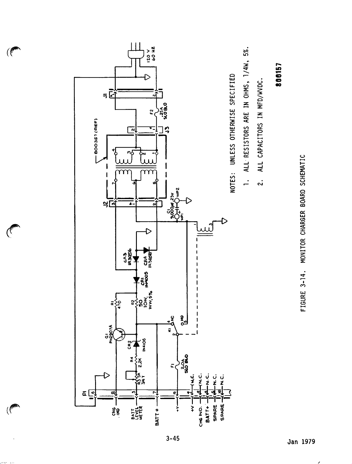
-f-t
S
LuuJ
ill
m
*i
v9
-£>
-13
— * J
^Tr I
uuuu
<!
i—
Q
UJ
t—i
U_
oo
i—i
s:
c_>
^
o
UJ
a.
CO
z
1—1
o
-J
-»
UJ
oo
•—<
3
a:
UJ
3C
I—
O
oo
OO
UJ UJ
_l
z
Z3
oo
UJ
1—
o
UJ
ce:
<c
oo
a:
o
tr
io
1—1
00
Ci
-J
_l
<c
r—
€S
o
>
3
*-^
2:
2T
. .
.
Q
Q
U_
i—i
OO
ca
o
h-
i—i
o
*<
Q.
•<
O
_J
_l
<:
CM
o
i—i
l—
<:
O
OO
Q
a:
<c
o
CO
cn
ui
CD
a:
"
T T Z
v—y~y~y~y—
CO
a:
o
co
DC
ZD
CJ3
i
3-45
Jan
1979
Page 83

3-13.
DC DEFIBRILLATOR
The
following
DC
Defibrillator
diagram
data
Defibrillator.
presentedinSectionVIprovides
for
the
paragraphs
subassemblies
circuit
3-14
through
description.
which
comprises
3-16
The
the
provide
interconnect
complete
the
the
LIFEPAK
interconnection
LIFEPAK6DC
6
wiring
3-14.
Main Board Circuitry
The
central
volt
of
these
inputtohigh-voltageDCpulses
functionofmain
pulses.
Entailed
provisionofsupply
control.
capacitor
energy
(e)
disconnectionofECG
mode
(g)
status
to
the
A.
On-Off
the
of
on-off
Kl
not
and
In
its
monostable
of
front
stantlyto+12
The
aspectsofactive
shunt
level
enabling
withdrawal;
selection;
(defibrillationofsynchronized
display;
patient.
Control.
main
transformerTlwill
relayKlis
coil
conducting.
theKlwiper
the
quiescent
emitter
the
POWER
panel,
(See
board
to
appearsatJ3-3.
groundisopen
and
flip-flop
switch,amomentary
grounds
volts.
defibrillator
andtocontrol
steps
voltages,
(d)
monitoring
and
(h)
Figure
The
+12
include
controls
control
(b)
high-voltage
initialization,
are:
dumpingofunwanted
circuits;
controlofstored
3-15).
volt
input
from
TheDCinput
eventuallybecompleted
energized.
Initially,
because
ControlofU5aismade
bypass
state,Q3is
baseatthe
path
involving
not
conducting
+12
volt
UlaQoutputishigh.
switchonthe
Jl-9,
thus
Figure
causing
3-16
traces
boardisto
the
power
on-off
(a)
energy-storage
pulse
timing;
stored
(f)
discharge
cardioversion);
charge
the
charger
pathtoterminal
v/hen
however,
transistor
viaafront
transistor
input
CIOtocharge
subsequent
U5ainthat
but
potential.
The
first
defibrillator
convert
+12
application
control,
and
active
(c)
stored
energy;
application
board
the
the
panel
Q3.
maintains
events.
to
1
coil
path
of
from
path
control
The
depression
almost
in
is
The
ground
state,
and
to
pin
which
then
until
about
+6-volt
12)islow,
WhileQ3is
level.
a
large
Later
charging
signaltoUla,
pin10triggers
lastsaslongasthe
CIO
has
discharged
on,
when
level.
that
its
theKlwiper
current
During
turnsonQ3.
current
chargesCland
that
3-46
Ulatoits
power
through
this
closes,itwill
would
switchisdepressed,
130K
period,
tendtodegrade
instable
ohm
(RN1-7to8)
theQoutput
C15tofull
not
switch
its
(Ula,
+12
volt
contacts.
Page 84
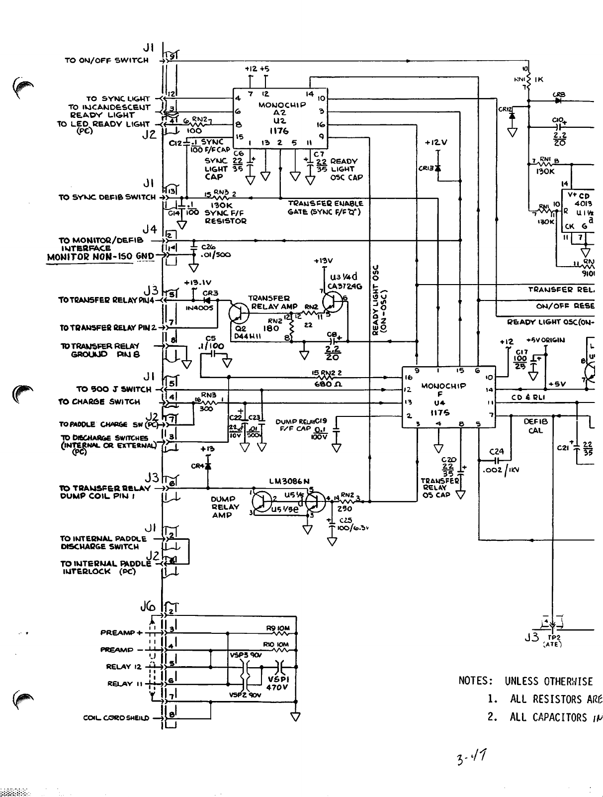
TO
TO
TO
TO
OU/OFF
TO
IVlCANDESCEklT
BEADY
LED
READY
SYWC
SYMC
LIGHT
DEFIB
SWITCH
LIGHT
LIGHT
SWITCH
Jl k
J4
TO
MONITOB/DEFIB
INTERFACE
MONITOR
TOTBAWSFEB
TOTOAMSFEfi
TO
TRANSFER
GROUUD
NON-150
BELAY
BELAY
RELAY
PIKJ6
-
GND
J 3
PlU4-<«$
IU4-«
PlM 2.
Jl
TO
©OOJSWITCH
TO
CHARGE
TO
PADDLE
TO
DISCHARGE
(INTERNALOREXT^RNaO"7£3
SWITCH
CHARGE
SW ^
SWITCHES''31
J3
TO
T0AV4SFER
DUMP
COIL
PlM
BELAY
J
-»
-«-
-»
»> ,
iTsf
-»-
0 1
ITS"
-<«
W
-»
IU
>r
_
ckTioo
^U
s
u
t*
%
+
IN400S
I3-IV
f
i M t
.l/lOO
CR4J&
I30K
SYWCF/F
EEStSTOB
C2fe
.OI/500
CR3
Q2
D44WII
3O0
+
13
DUMP
BELAY
AMP
+
C22J.C23
V
TQAWSFEQ
RELAY
RW2
180
LM3086N
C7
22
T
35
^7
TBAUSPEC
GATE(SYKJCF/Pt3'')
+
I3V
CA3724G
AMP
s
15
RKJ2
3^
fefiOA
dump
relavCis r
F/F
CAP
0.1 i
100
v
READY
LIGHT
OSC
CAP
ENABLE
U3 '/4-d
2
J
U
«n
O
r~
o u
j*>»
UJ O
I2.V
CRI32[
9 I
MOkJOCHlP
F
U4
JIT'S
3 ** S
V
C2D
22
35
TBAI4SFEC
BELAY
0*b CAP V
GRIZ
ao.
V
2.2
20
.7
RNI B
I30K
10
M^\t-B
13OK
14
V+CD
CK
4013
UIV«
G>
¥
-^-ws
TPAWSFEB
ON/OFF
BEADY
+
12
i5
C24
.002/IW
:£
.
100
CD
LIGHT
•6VOBI&IW
CI7
£BU
0EFI6
CAL
+
SV
0SC(0W-
C2i
BEL,
HESE
±22
:£
I
35
k
TO
IMTEBMAL
DISCMABGE
TO
IMTEBWAL
IUTERLOCK
COILCOROSHElLD
PADOLE
SWITCH
PADDLE
(PC")
PREAfMP-
RELAY
12
RELAY11-tJ-»S_
•
—»>^
J2
-ffl^j-
riii
IIII31
y
-*-»-»
I 1
till"
LUL
Mj,
11
ib
VSP3«XV
vspzqov
R9IOM
—^A/V—<>
RIO
•WVHi
H-Je
V5PI
470V
tOM
J-*^
J 3
TP2
NOTES: UNLESS
1.
ALL RESISTORS
V
2. ALL
•?
OTHERWISE
CAPACITORS
Mt
/*>
-•/?
Page 85
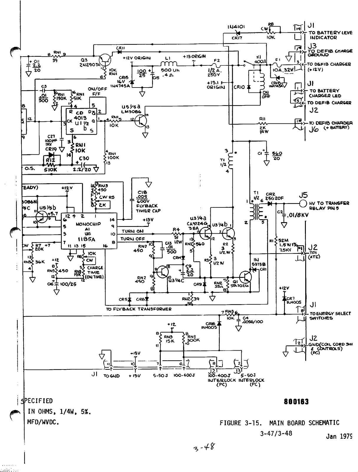
j+
Cll
±
2^2
<7™
12
O.S.
a RNI 9
P A A
A_Z-
3*3
Q3
2N2907AV
6 RNl F/F
51K
B CD
S b S
C21
_L
lOOpP x
|6
31
nBTilW]«0
5
IOK
2.1/20
OKJ/OFF
05
CRti
IOK.
RNl
IW4745A
IOK
CRlS
I6.V
+
I2VORIGIW
«±-
LM30&fc
IOO
25
T
+1
-T^5
LI
JTTTL
500
.*IL
Uh
+ 13
ORIGIN
JU.
F2
1/2
A.
2SOV
+ 1-5.1
OBIGIKJ
*-
lU«4lOl
—*-
CRI7
» » 0
CRIO
R8 ,
cwJ
—wv-*>
IOK
it
-»-
TO
BATTEBY
IWDICATOB
u
J3
»rTO
•TO
(♦12
DEFIB
D&.FIB
V)
Jl
,-»>-
TO
"^'
-rsTI
1—j^<-TODEFIB
BATTEBY
CHABGEB
LEVE
OIARGE
CHARGES
LED
CHABGEB
J2
-A/W-
Rll
2K
I^W
^
-TO
DEFIB
CHARGER
EADY)
>08feN
0k
»
U5'/5b
—(I
+
I2V
u.
12
II 13
+ e
MOMOCUIP
Al
U6
U35A
15
5>
™K
MOM
CHARGE
TIME)
Ifo
TO
TURW
TOBM
Cd52l
FLYBACK
T
tOOV
FLYBACK
TIMER
ON
OFF
GK&y.
TRAWSFOBMEfi
-H^V
CAP
♦12.
-X-
RN3
I5K
8 ,
RN3
300K
10
CR(6
IN40OS
7KN3fe
,
-A/W^fIOK. _L
_
T
V
C4
.0056/100
+I2V
[CRT
V^
-T)HVTO
IUAOOS
u
H
T5f.
TRANSFER
BELAY
(ATE^
Jl
.TOEWER&V
SWITCHES
JZ
^GWD(COlL
iWD
£ C
PIN
5
SELECT
CORD
-ROLS)
3HII
jSpecified
IN
OHMS,
MFD/WVDC
1/4W,
5%.
£
—r—
Jl
TO&UD
i=
+
I3V
S-5QJ
IOO-400J
J2^ J3' ,
I00-4OOJ
IUT&B.LOCK
(PC)
5
-50
INTERLOCK
LPC)
J
800163
"*>
FIGURE
-+ %
3-15.
MAIN BOARD SCHEMATIC
3-47/3-48
Jan
197S
Page 86

3-14.
Main
Board
Circuitry
(continued)
v*
A.
On-Off
Control
POWER
SWITCH
1st
U1A
l|
DEPRESS
(ON)
RESET"[/
—^
——**2SEC
U1A Q
U1B Q
(continued)
RELEASE
Q3
CONDUCTS
* '
r c
J '
' •
U5A CONDUCTS
2ND
|j
DEPRESS
(OFF)
[/-
i_r
FIGURE 3-16. ON-OFF CONTROL
When
Ula
finally
after
off
to
charger
to
off
itsQoutput
Kl
energized,
transformer
For
is
pulse
depressed,
enter
about
constitutinganew
causes
low.
path
POWER
Q3.
The
typeDflip-flop
input
reset
winding
comparable,
Ulb
transistor
path
thereby
Tl.
subsequent
through
sending
its
set
0.2
second,
theQoutputofUlb
Asaresult
to
ground.
revertstoits
switch
leading
first
so
that
U5a.
toggles
from
normal
except
C3.
state,
The
reset
release),
edge
Ulb.
became
flip-flop'sQoutput
Now,
high,
+12
completing
turnoffofthe
that
Again,
a'low
with
itsQoutput
clock
U5a
transistor
Kl
itsQpin
of
the
high
At
some
earlier
available,ithad
with
the
turningonU5a
voltstoground.
the
high
Ulb
does
the
POWER
pulsetoUla,
itsQoutput
revertstohigh,
inputtoUlb.
to
toggle
turns
wiper
accordingly
state
reverts
constitutesaclock
clock
capacity
+12
not
(about
to
time,
pulsed
wasalow
input
and
thus
The
volt
experienceareset
input,
0.2
second
high,
when
shutting
+12
through
that
to
Ulb
going
completing
Kl
relay
circuittothe
accordingly
the
switchismomentarily
pin
going
This
from
off,
10.
its
opens.
This
low.
the
second
previous
breaking
causes
After
leading
clock
high
the
input
volt
C3
switched
high,
the
action
high
Ula
to
edge
input
to
Kl
coil
(<
3-49
Page 87
3-14.
Main
Board
B.
Voltage
the
nominal
is
from
from
against
and
volts
outputatU6,
the
The
the
Circuitry
Supply.
defibrillator
+12
volts
tapped
charger
charger
CR18.
basesoftwo
outputatthe
base-emitter
from
transient
The
to
monochip
input
input
channeledtomonochips
tively.
the
+12
tiometer
pin7as
in U4.
C.
Control
centerinmonochips
areaready
to
two
lation.
flip-flop,
U6
isacharge
U6
providesinaddition,a+7
volts.
R7,
adjusted
the
reference
Initialization.
oscillator
selectable
StagesinU4
andanenergy-level
(continued)
The
control
module
for
the
the
load
(J3-3).
after
overvoltagesisprovidedbyZener
+5
volt
U6,
pin
supplyisderived
which
6.
This
emitter-follower
emittersisconsequently
diode
drop,or5
U6,U4and
and
indicatorDCloads
are
supplied
POWER,
SYNC,
from
and
sideoffuseF2and
The
nominal
filteringinLI
producesaregulated
+5.7
volts
transistorsinparallel,
volts.
U2,
+12
and
from
is
That5volts
pins5,14
the
CHARGE
applied
the
volt
OutputtedatU6,
pin
7,
it
is
theretoabout6volts,
U2S
andaflip-flop
modes:
voltage
The
U4,
synchronized
includeadump
for
control
and
U6.
the
energy-level
functions
Principal
whose
cardioversionordefibril
relay
comparator.Aprincipal
oscillator.
throughout
main
supplied
volts
C15.
applicationof+12
5.7
supply
board.
switch
directly
is
derived
Protection
diodes
+5.7
to
and
volt
volts
is
12
respec
derived
The
lamps
CR15
U5b&c.
minus
from
appliedtopoten
and
appliedtoU4,
comparator
on
the
board
stagesinU2
two
states
correspond
flip-flop,acharge
feature
of
J
^
v 7
As
of
POWER
U2 and U4.
It
dump
to
of
will
D.
Active
energy
depressing
charge
grounds
to
charge
to
high,
caus.es
J3-6,togo
also
has
their
partofthe
Ulb
during
switch
resets
flip-floptode-energized
non-charge
Ulb
goes
have
Control.
storage
buttononthe
common
the
charge
state,
its
energized
appliedtothe
those
turn-on
and
until
acts
the
high
stabilized
as
sync/defib
state.
ensures
After
capacitor
either
the
point
flip-flop
which
state.
units
low.
In
process,
shortly
an
reset
flip-floptodefibrillation
state,
Holding
before
Ulb-Q
can
CHARGE
adult
Jl-4,
at
causes
these
that
the
active
has
begin.
switchonthe
apex
J2-7.
U4,
pin
the
dump
Asaresult,
basesoftransistors
to
conduct
and
consequence,
tiedtoJ3-6,isenergized.
passively
normally
allowed
closed
the
relay
position
that
the
low
appearingatQ
after
pulse
the
to
the
and
states
first
the
until
+12,+7and
control
gone
high,
That
is
chargeupofthe
processisstarted
front
external
This
13.
flip-flopinU4
paddle.
constitutesaset
That
U4,
pin3goes
U5d
thus
the
Until
high-voltage
their
transfer
now,
completesa100K
terminal
depressionofthe
flip-flops
charge
theQterminal
+5
volt
entered.
in
mode,
the
flip-flop
supplies
panelorthe
Either
action
input
unit
switches
to
transition
to
high.
and
U5e
in
parallel,
collectors,
relay
the
coil,
contactstostay
tied
dump
coil,
de-energized,
ohm
resistor
high-
by
the
That
to
in
^
\ 1
3-50
Page 88
3-14.
Main
D.
Board
Active
Circuitry
Control
(continued)
(continued)
g
path
connected
provision
has
across
ensured
drainedofcharge
instrument
relay
will
drain
the
dump
the
bleed
In
transitioningtocharge
relay
a
high
thence
called
builds
imately
U6,
pin3ordering
initiate
*
delay
ohm
shunt
The
oscillator
exceeds
with
time.
mentary
then
complete
paralleled
positive
low
failure,
and
passive
offafull
coil
to
energize,
(+5
to
having
path
so
volts)
capacitor
signalCD&
until,
3.5
energy
gives
volts.
the
from
after
the
in
+3.5
volts,
That
form
at
forashorter
one
cycle.
transistors
and
essentially
storage
dump
U6,
the
high-energy
that
the
capacitor
and
therefore
with
closing
that
the
through
C21.
RLI
At
the
storage
U6,
output,
consequent
of
charge
been
energized,
subsequent
charge
internal
As
(charge
about
100
that
oscillatorinU6
capacitor
coil
sufficient
commandedonwhen
providesasquare-wave
appearingatU6,
pin
8),
variable
Each
50-usec
U3a
shorting
safe.
the
100K
within
capacitor charge-up
state
and
flip-flop
C21
charges,
delay
milliseconds,
level
capacitor
goes
it
charge-up.
high
period
high
and
U3b,
Ql
storage
capacitor.
initially
is
(Incidentally,
de-energizingofthe
ohm
20
seconds).
the
100K
thereby
has,
path
across
Now,
ohm
dump
signaling
in
addition,
resistancetoU4,
the
voltage
and
ready
constitutesacommand
to
time
to
before
the
pin
for
50
(about
from
thereby
collector
light
it
exceeds
operate
The
disconnect
charge-up
signal
output
10
and
100
to
unsymmetrical
(and
microseconds,
20
to
30
U6,
pin
10
driving
to
Ql
ground.
This
essentially
power
or
dump
the
capacitor,
however,
relay
may
the
opens
proceed.
dump
applied
pin
11
and
across
it
interface^
approx
via
thereby
millisecond
the
100K
begins.
U6,
pin
3
in
comple
usee)
turns
to
on
base
During
1-2
the
of Tl
maximum
flux
buildup
winding
of
this
During
emitter
phase
high
from
8
high
be
voltage
negative
almost
in
the
of
to
low
turns
shorted
immediately.
Tl
inducesahigh
endpoint
veyed
passes
through
through
50-usec,
increases
current
has
end
point6goes
negative
50
microseconds,C9has
signal
the
oscillation
low
and
to
high.
on
through
across
pulse
Tl-6
going
CR2
the
DC
current
from
zero
producesalarge
inducedalarge
negative.
voltage
of
Ql.
its
complement
The
transistor
U3c
C9
cannot
to the
to
J5,
After
begins,
significant
U3c,
collectortoground.
change
base
of
The
consequent
voltage
positive.Aresultant
and
output
the
normally
closed
through
to
Ql
magnetic
voltage
the
charged
the
50
with
terminal,
result
causing
instantly,
Ql,
turning
in
Tl
secondary
jack
J5.
contacts
primary
saturation
flux
in
Tl
Diode
high-voltage
usee
U6,
CR2
up
period
pin
U6,
is
C9
positive
prevents
via
10
pin
that
Inasmuch
the
that
quick
collapse
with
current
From
there,
of
winding
level.
in
Tl
secondary,
This
core.
coupling
connector.
the
base-to-
ends,
changing
the
8,
switching
the
U6,
plate
as
result
transistor
is
of
the
winding
pulse
off
board,
the
transfer
The
so
that
reverse
from
pin
to
the
a
off
flux
is
con
relay
it
3-51
Jan.
1979
Page 89

3-14.
Main
Board
D.
Active
and
capacitor.
through
relay,
As
secondaryisinductively
ground,
to
appliedtopin
turn-on
When
50-usec
current
Circuitry
Control
is
stored
The
another
and
thence
longasthe
the
magnitudeofthe
the
drop
across
line
all
the
on-period
ceases
(continued)
as an
discharging
16,
low
energy
in
(continued)
incremental
return
pathisthrough
setofnormally
charge
closed
on
the
series
contactsonthe
backtogroundatJ3-8onthe
currentisflowing,
driven
conducting
ofU6maintains
as
longasthe
storedasTl
has
been
Tl
secondary.
negative
negative
diode
the
negative
with
voltage
CR6.
turn-off
condition
This
fluxasa
transferredtothe
energy
inductor
storage
LI,
transfer
main
terminal5of
respect
being
board.
to
limited
negative
line
high
endures.
resultofthe
storage
capacitor,
Tl
signal,
and
the
previous
/-/*%
Consequently,
signaltoU6,
tained
for
Tl-5
pin16ends.
an
dependsonthe
14
of
U6.
During
value
long
lations in Tl.
In
25
the
on-off
to
cretely
300
charging
voltage
the
This
SELECT
interconnected
potential
the
setting,
SELECT
then
or
to
wiring
such
that
enough
all,
usee.
RC
(about10usee)todamp
the
off
The
turn-on
circuit
charging
charge
the
storage
selectable
or
400
joules).
processisstopped
across
desired
amount of
quantityisselectedbyappropriate
switchonthe
end
of
voltageonthe
the
switched
switch
back
Jl-7
(dependingonjoule
ground
harness
wiper
through
via
J2-8
revertstoground
The
additional,
fixed
valuesofR5,
calibration,
the
fixed
("flyback")
final
phaseofa
phaseisset
externaltoU6,
cycles
suchasthe
capacitor
energy
levels
An
optional,
when
the
capacitor
joules.
front
to
the
main
52
megohm
energy
andaselected
panel.
board
resistorRlwhose
storage
path
from
interconnect
range).
and
J3-2
respectively
and
the
paddle
potential;
turn-off
period.
RM3,
and
potentiometerR5is
portionofthe
to
pin
15.
one
phase,
This
C18
out
energy-dissipating
charging
50
usee
Thousands
just
fixed
connectedtopins1and
off
by
describedisrequired
stepwisetoone
(5,
10,
20,
30,
tenth
the
levelis500
incrementally
reachesamagnitude
settingofthe
The
wiper
at Jl-8and
of
thus
high
capacitor.
Jl-8
passes
resistoronthe
wiringtothe
Those
and
connectors.
In
through
main
two
points
interlocksonthe
i.e.,
the
negative
however,issus
period
adjustedtoa
phase
lasts
oscil
cycle
of
lasts
about
adjustingR6in
of
successive
nine
dis
50,
100,
joules.
200,
The
increasing
corresponding
ENERGY
the
switch
to the low
end
senses
any
given
the
control
is
ENERGY
panel,
boardatJl-6
are
connected
to
3-52
Jan.
1979
Page 90

3-14.
Main
Board
D.
Active
The
voltage
voltage,
52
megohms,
on the
at
J5
comparator.
6.2
volts,
7.
When
switches,
flip-flop
its
previous
2-volt
stop
halts.
U6
has
up
oscillator
has
also
flip-flop
two
concurrent
respectively,
U2.
the
LED
period.
a
ground-level
to
light
progress,
1
Hz
capacitor
Circuitry
Control
at
that
whereRis
control
is
conveyedtomonochip
obtained
the
signal
causing
drops
(continued)
(continued)
Jl-8
proportion
panel.
The
isasmall
comparator
from
climbs
the
the
CD &
greater-than
level.
operating.
While
remained
remained
Each
lamp
Each
for
frequency
This
the
high
was
in
U4
was
highs,
and
positive
on
the
negative
output,
that
both
C7.
lights
is
causes
In
consequence,
charging
commandedtooperate.
high,
commanded
theretostartasquare-wave1Hz
half
apex
0.5
determined
equaling
the
resistance
That
fraction
reference
potentiometer
to
this
charge
RLI
3.5
the
process
at
the
level
at
the
conveyed
cycle,
paddle
half
cycle,
causes
second
will
blinkonand
proportion
the
U4,
pin
reference
flip-flop
signal
volt
output
level
charge-up
charging
has
it
level
to
its
to
monochip
appearing
to
light
appearing
the
CHARGE
period.
by
U2
internal
of
ratio
of
of the
5,
voltage
R7
in U4 to
betweenRand
the
increasing
the
and
level,
at
(typical
oscillator
of
been
proceeding
switched
Meanwhile
it
attained
energized
U2,
at
pin
for
lamp
Thus
during
off
onceasecond.
elements
the
storage
Selected
signal
is
applied
U4,
input
approximately
comparator
reset.
pin
5V)
in
the
storage
to
when
pin
v/hen
state.
pin
10
oscillator
8 of
that
at
on
pin
the
0.5
6 of
the
capacitor
R+
resistor
voltage
to
to
U4,
The
11,
from
to
the
U6
to
capacitor
pin
the
charge-
3 of
the
dump
These
and
9
U2,
causes
second
U2
front
charging
plus
a
pin
output
reset
2 of
U4
in
as
panel
The
When
the
charge-up
selected
Pins8and6will
steady
subsequently
bleeds
5%,
exceeded
condition.
until
lighting
down
the
energy
either
joule
and
re-initiationofthe
switch
E.
Defibrillation
is
applied
In
in
that
is
defib
to
mode,
rotated
mode,
the
(indicatedbysteady
can
command
by
depressing
paddles
or
the
oscillator
level
of
before
sufficiently
level
the
In
that
the
having
go
fixed
both
application
comparator
comparator
case,
desired
charge-up
or
the
Discharge.
pin
4 of
SYNC
when
lamp
the
selected
lightingofthe
its
dischargetothe
both
discharge
single
switch
3-53
been
high
the
CHARGE
to
drop
output
the
charge
main
While
U2
on
the
is
commanded
reached,
and
low
lamp
of
the
the
capacitor
hysteresis
will
charge
indicator
level
process,
power
maintainsasteady
is
the
front
amount
sync/defib
charge
patient.
switches
on
the
simultaneouslyonthe
control
to
pin
respectively,
and
the
stored
lag
revert
is
restored
or
the
turned
panel,
of
energy
lamps),
The
panel.
cease
2 of
apex
charge,
voltage
of 5%
to
not
lamps
after
energy
off.
flip-flop
high
keeps
has
command
operating,
U6
goes
causing
lamp.
that
more
will
will
be
ready
blink,
operator
select
which,
that
been
the
is
Jan-
lamp
stored
operator
effected
^79
the
low.
If
charge
than
in
U2
off.
external
Page 91

3-14.
Main
Board
E.
Defibrillation
Discharge
at
energy
single
state
shot
plishes
the
instrumentisused.
this
sync
Circuitry
switch
U4,
pin
level
shot
of
about
flip-flop,
four
sync-defib
reset
mode,
(b)atU2b,
that
flip-flopinon
sequent
U3d,
through
in
storage
whichinturn
J3-7toenergize
U4,
the
(continued)
Discharge
despression
16,
traversesatransfer-enable
comparator
multivibratorinU4
200-millisecond
going
things:
flip-floptodefib
is
academic.
resets
the
pin6,the
capacitor
200-msec
flip-floptode-energized
to
shunt
appliedtothe
before
the
energy
patient.
any
significant
(continued)
grounds
J2-3.
outputishigh)
to
transitiontoits
duration.
highatU4,
(a)
appliedtoU2,
(With
the
The
pin9for
mode
instrument
same
action,
instrumenttothe
set
inputofthe
status
turnsontransistor
singleshot
storage
during
the
discharge,
the
transfer
output
state.
This
capacitor
The
dischargeisaccomplished,
amountofthe
(c)itturnsontransistor
relay
resets
evenasthe
energyisbled
This
ground,
gateinU4
and
causes
the
setorhigh
The
output
the
pin
16,itactstoreset
for
the
next
currentlyindefib
however,
safe
mode
on-off
flip-flop,itholds
transients
Q2,
transmittingalow
and
the
causes
the
of
200-msec
time
occurring
for
causedbysub
(d)
internally
dump
bleed
charge
down.
appearing
(when
the
transfer
the
single
accom
the
mode,
in
next
relay
use.)
resistor
is
however,
/^jjk
The
energizingofthe
and
inductor
relay
pins6and9,thencetopaddle
andonto
In
addition,
closed
ECG
disconnecting
F.
Synchronized
the
automatic
sync/defib
the
defibrillator
both
are
defibrillation
on
the
front
In
that
switch
statesitis
+2
the
low,
U2,
U4,
toggles
volts
flip-floptosync
causing
pin2goes
pin1,disables
received.
at
J4-2,
combination
the
paddle
the
"Quik-Look"
the
Cardioversion.
turn-on
flip-flopinU2todefibrillation
turned
panel.
joint
configuration,
in
from
the
the
The
appearsasa
whichisappliedtotwo
transfer
via
the
electrodes.
energizingofthe
contactsonthe
monitor
preamplifier
When
sequences,asexplained
and
monitor modules
on,
mode
either
can
synchronized
be
selectedbymeans
each
the
defib/sync
to
the
opposite
paneltoJl-13
status,
SYNC
hightoabout
systole
lamptolight.
+4.3
the
transfer
pulse,
+5
volt
circuits;
relay
connects
relay
DPDT
connector
transfer
transfer
from
the
defibrillatorisused
are
cardioversion
momentary
flip-flop
state.
and
its
outputatU2,
volts.
gate
received
signalof10
(a)
from
Switch
via
C12asa
Moreover,
untilasystole
from
appearingatU2,
the
storage
wipers
pins
relay
the
mode.
connected
opens
relay,
paddle
earlier,
of
the
to
Jl-11
However,
together
SYNC
capacitor
transfer
and
normally
thus
electrodes.
set
mode
switch
depressionofthe
whicheverofthe two
depression
clock
applies
pulse
pin4goes
itsQoutput
The
high,
applied
pulse
the
monitor
millisecond
interface
duration,
pin3,it
Jl-8,
alone,
the
when
and
or
SYNC
to
steady
at
to
is
/^
^ /
3-54
Page 92

3-14.
Main
F.
Board
Synchronized
Circuitry
Cardioversion
(continued)
(continued)
a
turns
10
to
the
msec
U2,
SYNC
is
lengthenedto80-100
pin
1).
approximate
the
systole
the
10-msec
the
transfer
As
in
defib
charge
discharge
the
ready
switchorswitches
transfer
flip-floptoits
results
of
R-wave.
G.
Energy
while
to
be
operator.
The
rotation
the
the
voltage
ground.
The
U4,
U4
the
to
as
in
the
stored
Level
the
storage
the
previously
dumped
energy
and
The
selected
from
wiperisin
circuit
division
The
voltageatU4,
pin
5,
input
is
caused
dump
non-charge
flip-floptode-energized
capacitorisdumped,
is
suspended.
position,
normal
lamp
0.1
signals
5-volt
gate
mode,
condition.
gate.
defib
off
The
visible
second
per
are
pulseisone
in
U4.
another
The
200
millisecond
mode;
for80to
being
When
subsequent
chargeisnow
Change.
If
the
capacitorischargingupor
selected
charge-uptothe
sequenceisas
switchonthe
one
settingtoanother
transit.
between
the
low
resistorsinthe
undivided
high
pin5,quickly
exceeds
to
transition.
status.
Asaresult,
and
When
the
select
sequencing
100
milliseconds
msecasthe
blinking
heart
beat
off
informs
received;
of
the
coincident
requisite
the
sends
enabling
gateisenabled,
the
discharge
transitionofthe
with
the
in
synchronization
operator
level,
new
follows:
Switch
end
state
rotation
of
accomplishes
exception
selectsanew
that
charge
limit
front
panelisof
opens
52
megohm
energy
voltageisapplied
risesto+8
about8volts,
The
changed
an
status
the
energyinthe
if
charging
switchisthen
resumes.
was
(in
effectofC6
of
the
lamp
the
operator
(b)
appearingatU4,
conditions
the
transfer
depressing
command
the
that
the
with
the
energy
afterithas
stored
will
the
be
institutedbythe
wiper
therefore
resistorRland
select
switch
throughRlto
voltsormore.
energy
comparator
and
in
progress,
dump
the
charge
placed
U2,
the
connected
for
that
that
pin
enabling
gate
the
through
single-shot
same
discharge
detected
level
charged
earlier
the
circuit
briefly
type
will
where
while
opens
the
circuit
C4.
When
comparator
output
resets
flip-flop
storage
the
charging
anew
onaset
15,
is
to
in
the
H.
500
energy
unit,a500
a
500
resistor
the
switch
With
circuitinU4
(See
Joule
storage
joule
for
energy
and
the
instrumentonbut
Figure
Option.
When
the
500
capacitorisemployed
joule
switchisaddedtothe
voltage
select
the
3-17).
settingisaddedtothe
divisionatJl-8.
switchisin
500
JOULE
produces
With
switch
before
+1.5
voltsatthe
the
energy
3-55 Jan. 1979
Joule
front
500
joule
must
charging
select
optionisinstalled,a46
insteadofthe
energy
panel,
To
initiate
position,
be
depressed
starts,
comparator
switchin500
standard36uf
select
as
is
switch,
an
appropriate
charging
both
the
CHARGE
simultaneously.
the
comparator
input,
U4,
JOULE
uf
and
when
pin
setting
5
Page 93

3-14.
Main
H.
Board
500
that
500
to
Circuitry
Joule
+1.5
Joule
Jl-5onthe
(continued)
Option
voltsisconveyed
position
(continued)
via
voltage-division
main
board
and
Jl-8,
the
select
resistor,
thencetoU4,
and
pin
switch
wiper,
interconnect
12.
C
the^
wiring
With
the
+1.5
to
U4,
pin
13,byactuationofeither
inhibited.
Actuationofthe
voltsatU4,
voltstogroundsothat
switch,
charge
PCB
+
HARNESS
Jl
(the
charge
flip-flopinU4
I
20K
with
commandatU4,
to
>
J5
i
300K
+12
pin
12,acharge
500
JOULE
concurrent
pin
charge
state.
6
command,
charge
switch,
switch
will
inputted
will
short
actuationofeither
13),
now
gated,
^
500
JOULE
SWITCH
will
->T0Ji-5
CHARGE
INHIBIT
be
the
+1.5
charge
set
the
PADDLE CONN.
FIGURE
Interlocks.
ground,
in
the
in
EXTERNAL
PADDLES
3-17.
establishing
main
PADDLE
Figure
board
energy
i
INTERLOCKS
3-17
shows
the
voltage
level
3-56
n
PATHTOGROUND
the
paddle
division
comparator.
n,
INTERNAL
PADDLE
interlock
for
energy
paths
to
sensing
Page 94

c.
3-14.
Main
Board
!•
Interlocks
With
and
Thus,
resistors
and
If
switchisin
through
storage
not
charging
If
storage
via
pin
J.
Battery
(from
voltage
diode
R8
The
actually
In
the
This
of
Circuitry
(continued)
adult
J3-2
the
the
external
are
the
low
are
100-400
ground
grounded
potential
normally
or
path
any
J2-8
is
broken,inany
capacitoratleast
occur.
the
As
and
ground
discussed
dump
interlock
capacitor,
an
energy
5,
with
select
the
result
Monitoring.
the
battery
levelisdroppedby8.2
and
CR17)
Jl-14
and
to
the
readingofthis
under
calibrating
battery)
reading
full
battery
the
the
and
correspondstothe
(continued)
paddles
via
employed,
the
jumpersinthe
endsofboth
100-500
through
low
range
grounded
(namely
bank).
J3-2isbroken
setting
high
partly
under
any
chargeonthe
energy
pathisbroken
the
+12
voltsatRN3,
via
switch
that
For
J6-1
pathtoJl-8
chargingisinhibited.
battery
and
condition
the
volts
the
differenceisapplied
BATT
LEVEL
meteronthe
meterissignificant
load,ofthe
meter,
R8
is
+10.5
adjusted
defibrillator
voltsissubstitutedatJ6-1
for
voltage
charge
remains.
main
board
paddle
banksofvoltage
the5to
while
(5-50)orif
range
charged,
storage
setting,
level
but
the
change,
capacitor.
with
pin8,willbeapplied
and
comparator
monitoring,
defib
charger
(the
fixed
through
defibrillator
only
meter
when
charge-up
deflectiontocenter
experienced
points
connectors.
division
50
joule
the
energy
the
ground
and
with
voltage
no
division
this
chargeonthe
the
assembly)
voltage
adjustable
the
when
J2-8
bank
select
path
the
does
will
input
+12
halt
U4,
volts
supply
across
panel.
battery
circuitry.
Zener
resistance
is
(for
scale.
only
20%
3-15.
Defibrillator
three
main
functions:
defibrillator
battery:
Charger
and
automatic
Board.
conversionofline
board;
transfer
The
charging
between
defibrillator
the
AC
115-voltACconfigurationisdescribed
working
doubled;
The
VDC
to
directlytoa
Filtering
to
power
Cl,
TransistorsQland
square-wave
producea20
voltagesatcollectorsofQl,
otherwise
AC
conversion
to
generatea20
12
volts
the
block
C2,
radio
line
frequencies.
and C3 is 150
DC.
oscillator,
kHz
the
involves
kHz
In
the
full-wave
bridge
frequency
output,
VDC.
Q2
and
output
same
square-wave,
initial
bridge
interference;
The
transformerT2are
the
to
Q2
description
rectification
and
step,
employing
series
nominal
the
inductorLIserves
no-load
transistors
transformer
3-57 Jan. 1979
charger
to
DC
for
alternative
the
two
power
below.
and
suffices
to
Cl
150
For
and
(see
VDC,
square-wave
line
AC
diodes
CR1
applicationtothe
power
the
is
board,
source,
sources.
230
C2
should
Figure
use
of
volt
be
3-18).
the
performs
The
option,
150
rectification
applied
through
4.
principally
capacitorsCland2bypass
rectifier
principal
conducting
Tl.
output
across
elementsofa
alternately
to
a
basic
'
Page 95

CRI4
CRI5
CR5
IN3470
Q3
2N4400
I
Q,/T^>kDTS423
R3
.43
2W
WW
C2>
.OI/IKV
33K
IW
cc
T!
c@-
Rl
BLK
WP-
MR6I2
330/
200
WW
C5+
3V
IO%
MR8I2
3W
CR6
1N3470
.033 7
!
C4
DT5423
100
02
—<D:
—©•
^D-
V
CRI2
IN4005
Rl
I
4.3KI/2W
CC
i i
/7-7SRH
a*
48
0'2)
VDC
Page 96
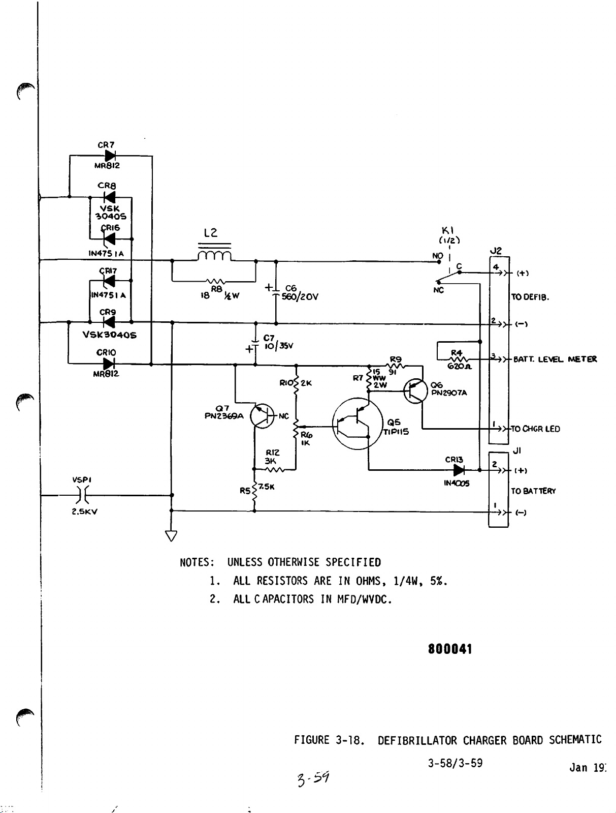
=i»-BATT.
LEVEL.
METER
NOTES: UNLESS OTHERWISE
1.
ALL
RESISTORS
2.
ALL
CAPACITORS
FIGURE
5-57
SPECIFIED
ARE
IN
IN
MFD/WVDC.
3-18.
OHMS,
1/4W,
DEFIBRILLATOR
5%.
800041
CHARGER
3-58/3-59
BOARD
SCHEMATIC
Jan
19;
Page 97
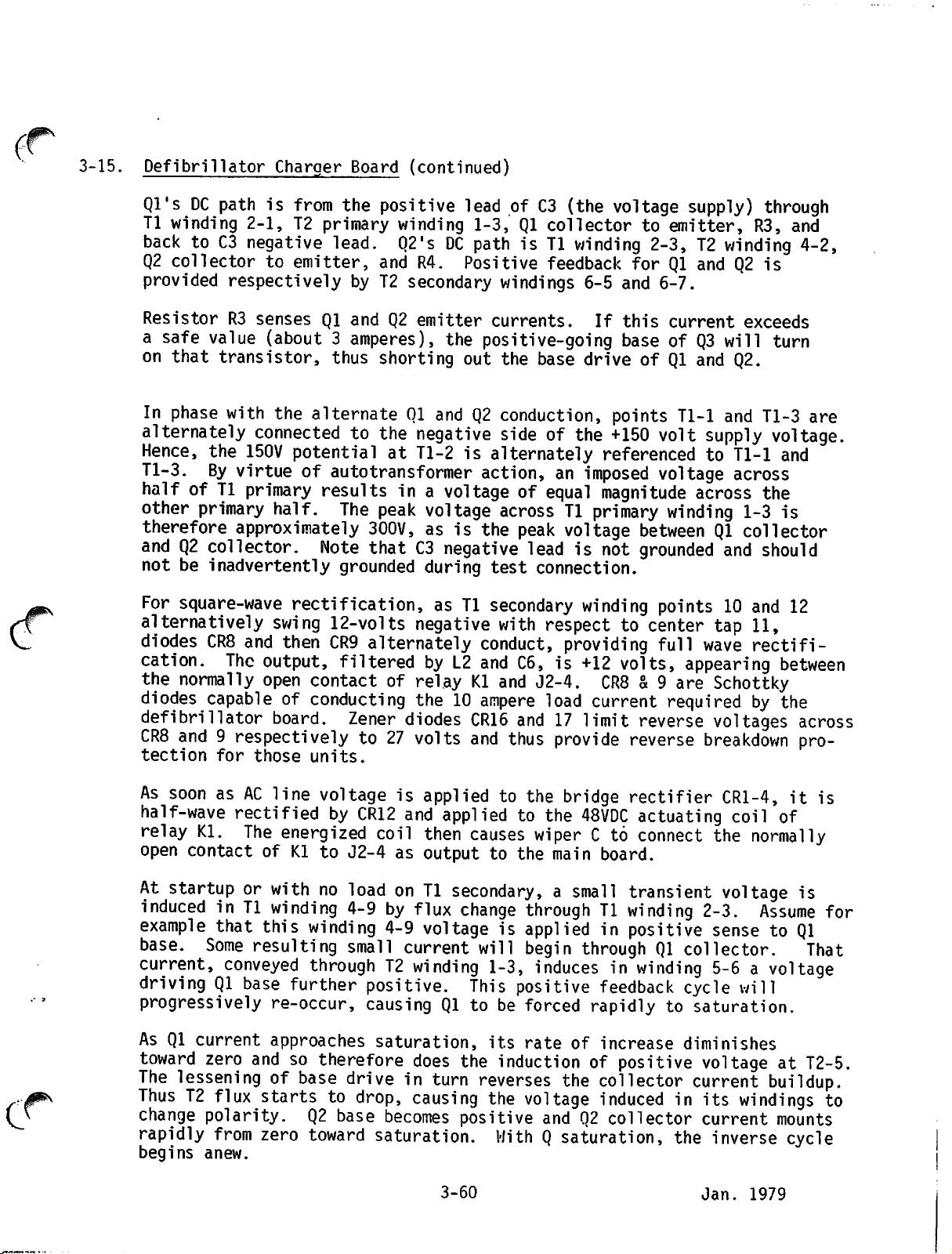
e
•0^\
3-15.
Defibrillator
Charger
Board
(continued)
Ql'sDCpathisfrom
Tl
winding
backtoC3
Q2
collectortoemitter,
provided
ResistorR3sensesQland
a
safe
on
that
In
phase
alternately
Hence,
Tl-3.
halfofTl
other
primary
therefore
and
Q2
not
be
For
square-wave
alternatively
diodes
cation.
the
normally
diodes
defibrillator
CR8
and9respectivelyto27
tection for those units.
2-1,
T2
negative
respectivelybyT2
value
(about3amperes),
transistor,
with
the
connectedtothe
the
150V
potentialatTl-2isalternately
By
virtueofautotransformer
primary
half.
approximately
collector.
inadvertently
rectification,asTl
swing
CR8
and
then
The
output,
open
capableofconducting
board.
the
primary
lead.
thus
alternate01andQ2conduction,
resultsina
The
Note
grounded
12-volts
CR9
filteredbyL2
contactofrelayKland
Zener
positive
winding
leadofC3
1-3,Qlcollectortoemitter,
Q2'sDCpathisTl
and
R4.
Positive
secondary
Q2
emitter
the
shorting
negative
windings
currents.
positive-going
out
the
sideofthe
action,animposed
voltageofequal
peak
voltage
300V,asis
acrossTlprimary
the
peak
thatC3negative
during
negative
alternately
test
secondary
with
conduct,
and
C6,is+12
the10ampere
diodes
volts
CR16
and17limit
and
thus
(the
voltage
winding
feedback
6-5
If
2-3,T2winding
for
Ql
and
6-7.
this
current
baseofQ3
base
driveofQl
points
+150
referencedtoTl-1
volt
voltage
magnitude
winding
voltage
leadisnot
connection.
winding
betweenQlcollector
grounded
points10and
respecttocenter
providing
full
volts,
J2-4.
load
CR8
& 9
current
requiredbythe
reverse
provide
reverse
supply)
R3,
and
Q2
exceeds
will
and
Q2.
Tl-1
and
supply
across
across
1-3
and
tap
11,
wave
rectifi
appearing
are
Schottky
voltages
breakdown
through
and
4-2,
is
turn
Tl-3
are
voltage.
and
the
is
should
12
between
across
pro
As
soonasAC
half-wave
relay
open
At
Kl.
contactofKl
startuporwithnoloadonTl
inducedinTl
example
base.
current,
that
Some
conveyed
drivingQlbase
progressively
As
Ql
current
toward
The
zero
lesseningofbase
ThusT2flux
change
rapidly
begins
polarity.Q2base
from
anew.
line
voltageisappliedtothe
rectifiedbyCR12
The
energized
to
J2-4
winding
this
resulting
4-9byflux
winding
small
throughT2winding
further
re-occur,
approaches
positive.
causingQlto
andsotherefore
driveinturn
startstodrop,
zero
toward
and
appliedtothe
coil
then
causes
as
outputtothe
secondary,asmall
change
4-9
voltageisappliedinpositive
current
will
1-3,
This
saturation,
does
its
the
reverses
causing
becomes
saturation.
the
positive
WithQsaturation,
3-60 Jan. 1979
bridge
48VDC
wiperCto
main
rectifier
actuating
connect
board.
transient
throughTlwinding
begin
throughQlcollector.
inducesinwinding
positive
be
forced
rate
feedback
rapidlytosaturation.
of
increase
cycle
diminishes
inductionofpositive
the
collector
voltage
andQ2collector
inducedinits
current
the
CR1-4,itis
coil
the
voltage
2-3.
of
normally
is
Assume
for
sensetoQl
That
5-6avoltage
will
voltageatT2-5.
buildup.
windings
current
inverse
mounts
to
cycle
Page 98

3-15.
Defibrillator
Thus
T2
flux
current
TransformerT2operatesinthe
fact,
foraclose
waveform.
sinusoidal
Asaresult,Tland
the
If
drains
the
and
augmenting
alternative,astep-down
line
voltage
off
normally
12-volt1ampere-hour
output
As
terminal
longasline
connected
charged.
the
24-volt20kHz
consistsofCR7,
DC
to
C7.
transistor
zener
diode,
makeQ5collector
charging
it
current
control
when
panel.
the
Charger
and
the
induced
approximationtothe
Wave
line
squareness
frequencies,
drops
throughKlcoil,
closed
Board
current
the
sharp
T2
out,
contactsothat
(continued)
oscillate
voltage
saturation
and
together
the
allowing
makes
transformer
battery,
point.
voltageisappliedtoKl
from
supplying
The
charging
output
CR8,
The
trickle
Q5.
For
emittertocollector.
current
output
currentisobtained
fromTlwinding
CR9
and
currentismaintainedat100
voltage
regulation,
100
currentisflowing,
that
chargerisdisconnected
will
light
Diode
CR13
the
prevents
and
so
in
step
output
saturated
ideal
relative
are
from
Tl
secondary
flux
density
characteristicofQl&2,
square-wave
high
frequency,
for
efficient
much
lighter
operatingatline
chargeonsmoothing
rapid
the
willbeconnected
through
CR10,
mA.
also
which
PotentiometerR6is
The
servestoturnonQ6
LED
called
battery
from
actuationofKl
alternative
relay,
J2-4
and
through
10-12.
apply
transistorQ7is
R7
drop,
BATTCHGonthe
discharge
line
power.
does
the
Tl
primary
10-12.
region.
transformer
compared
transformer
and
less
This
makes
output
to
action.
bulky
frequency.
than
capacitorC8quickly
wiper
power
from
the
batteryisdis
is
instead
source,
Jl-2tothe
rectification
The
bridge
approximately24volts
mA
by
means
used
adjusted
becauseitindicates
and
pass
to
the
Jl-5
trickle-
of
rectifier
of
as
a
to
through
defibrillator
throughQ5collector
^
( J
3-16.
Test
maintain
Load
Board.
indicator
serves
settings
With
on
the
both
discharge
seeing
either
cathodeofZener
of
CR2
Cl
minus22volts.
Ql
turnsonQ2.
the
collectorofQ2
until
drained,
when
the
to
200
the
paddles
front
discharge
200
indicator
test
that
and
panel,
switches.
voltageisimpressed
approximately
polarity,ispolarizedbyrectifier
is
22
volts,
the
energy
Ql,
Q2
The
test
joulesisdischarged
the
100
areatleast
load
circuit
dark
when
defibrillator
100
restingintheir
the
charged
Either
capacitorisdischargedbydepressing
paddle
acrossRlandR2in
1.3%ofthe
diode
The
CR2
the
voltage
When
R3
conductionofQ2
going
high
storedinCl
and
the
LED
is
input.
positive.
acrossR3is
potential
latches
is
dissipated.
turn
off.
joules
approximately
normal
postponedatleast30secondstoallow
to
be
dissipated.
is
designed
through
stored
the
is
discharged.
charges
correct
locationonthe
maybeon
This
fraction,
bridge
Because
drop
exceeds
lights
Ql.
The
next
heat
the
the
voltage
LED
CR1.
Q2
conductionisextended
When
test
dissipatedinRl
to
light
load
at
either
series,
CR1sothat
breakdown
the
and
to
It
energy
(see
Figure
contact
plate.
with
which
maybeof
the
across
thereby
select
3-19).
plates
The
R2
voltage
approximately2volts,
In
addition,
that
capacitor
discharge
and
is
must
R2
be
3-61
Jan.
1979
Page 99
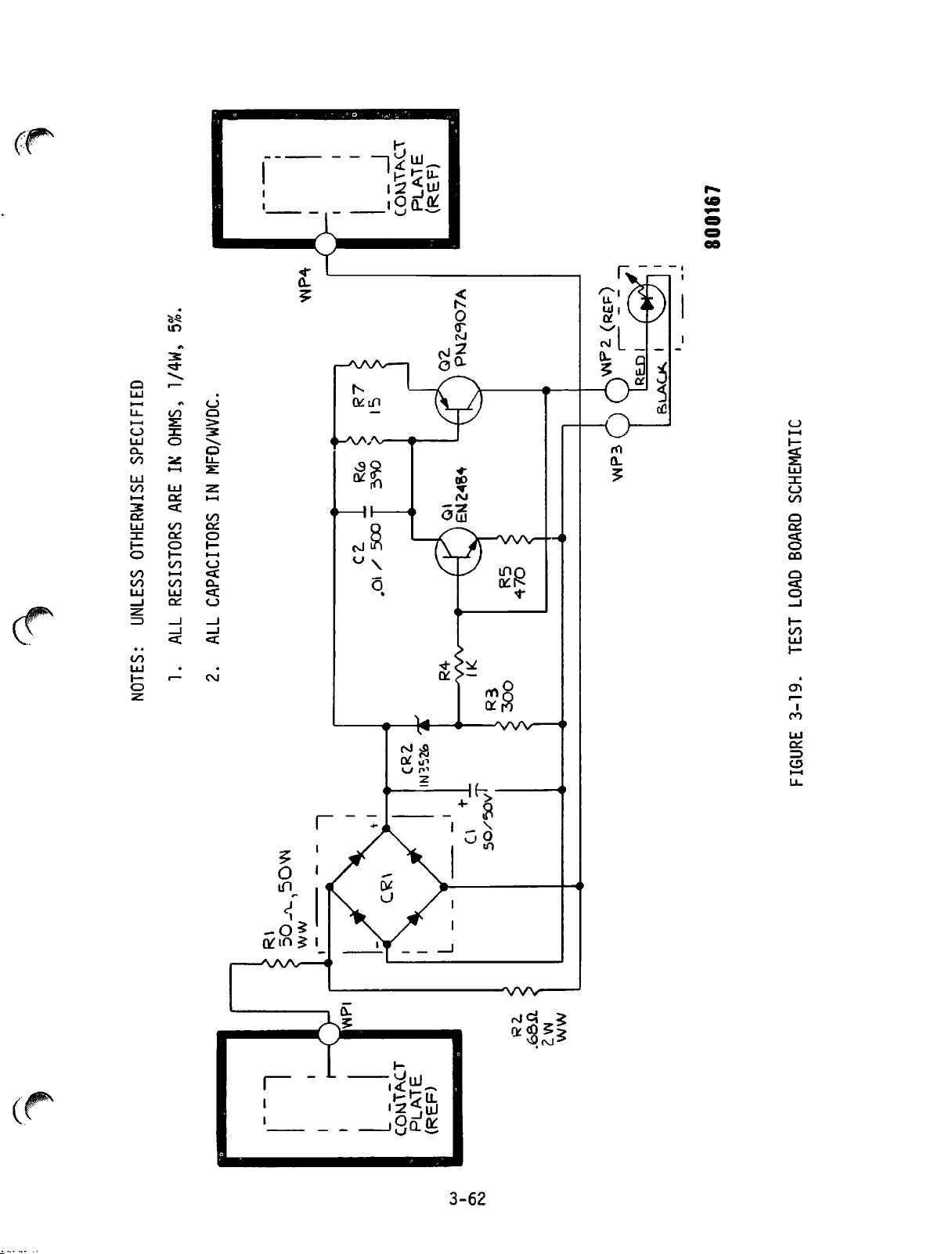
5%.
1/4W,
OHMS,
SPECIFIED
IK
800167
OTHERWISE
ALL RESISTORS ARE
1.
NOTES: UNLESS
ALL CAPACITORS IN MFD/WVDC.
2.
BOARD SCHEMATIC
LOAD
TEST
3-19.
FIGURE
PLATE
(REF)
CONTACT
co
R2L
.6SH
WW
Page 100

4-1. INTRODUCTION
SECTION
MAINTENANCE
IV
/T$P\
4-2.
4-3.
This
procedures
section
for the
provides
listofrecommended
for
helpinfault
calibration,
qualified
tion
should
The
section
part
Subsequent
by the DC
GENERAL
The
following
for the
which
cleaning
Warranty.
workmanship
cable
any
products
provided
described
personnel
presentedinSection
be
returned
provides
parts
defibrillator.
instrument.
include
information.
LIFEPAK6is
and
stylus90days.
proper
in
and
is
foraperiod
which
the
isolation.
component
to
organized
general
are
paragraphs
warranty,
provetobe
use
operating
maintenance,
LIFEPAK6instrument.
test
equipment
Troubleshooting,
removal
thoroughly
III.
Physio-Control
into
three
information
presentedbycardioscope/recorder
4-3
through
This
section
test
equipment,
warranted
of
one
Physio-Control
and
maintenance
and
servicing
and
Included
calibration
andatroubleshooting
repair,
shouldbeattempted
familiar
Circuit
applicable
is
against
year
defective
service
with
for
major
4-6
divided
repair
from
the
boards
servicing.
parts.
to
provide
into four major
all
defects
date
will
during
procedures
manual.
circuit
needing
both
general
techniques
of
repairorreplace
the
are
The
delivery:,
herein
is
guide
test
only
descrip
repair
first
units.
followed
information
and
in
parts
warranty
followed
a
and
by
major
topics
and
patient
period,
as
4-4.
All
defective
Control,orits
planationofthe
Service
performed,
Controlorits
Control be cause to void this warranty.
No
other
assume
either
Test
calibration
any
inplied
Equipment.
specific,
other
listed
test
may be
productsorcomponents
authorized
failure.
other
authorized
party
is
authorizedtomake
liability
or
in
Test
of the
LIFEPAK6are
commercially
equipment
used.
than
agents
for
Physio-Control
writing
instruments
available
with
specifications
service
center,
Transportation
stylus
may,
will
be
suitable
listed
test
4-1
must
be
returnedtoPhysio-
withadetailed
charges
must
be
replacement,byother
at
the
discretionofPhysio-
any
other
products.
warranty,orto
No
other
recognized.
for
maintenance
in
Table
instruments
4-1.
are
Although
recommended,
equivalenttothose
ex
prepaid.
than
Physio-
warranty,
and
 Loading...