

Page 1
XP 600 XP 1000
XP 2000 XP 2100
XP 3000 XP 3100
XP 5000 XP 5100
POWER AMPLIFIER
AMPLIFICADOR DE POTENCIA
功率放大器
XP 5100
User’s Manual
Manual del Usuario
使用手册
English / Español / 简体中文
Page 2

XP 600/1000/2000/2100/3000/3100/5000/5100
POWER AMPLIFIER
AMPLIFICADOR DE POTENCIA
功率放大器
CONTENTS
INTRODUCTION........................4
FEATURES.................................4
INSTALLATION...........................4
FRONT PANEL DESCRIPTION.5
REAR PANEL DESCRIPTION....5
SPECIFICATIONS......................8
DIMENSIONS...........................23
BLOCK DIAGRAMS..................25
CONTENIDO
INTRODUCCION..............................11
CARACTERISTICAS........................11
INSTALACIÓN..................................11
DESCRIPCIÓN DE PANEL FRONTAL
DESCRIPCIÓN DE PANEL DORSAL
ESPECIFICACIONES......................15
DIMENSIONES................................23
DIAGRAMAS DE BLOQUE..............25
...12
.....13
目录
简介................................18
特色................................18
安装................................18
正面板功能说明..............19
背面板功能说明..............19
规格................................21
尺寸................................23
线路图............................25
Phonic preserves the right to improve or alter any information within this document without prior notice
Phonic se reserva el derecho de mejorar o alterar cualquier información provista dentro de este documento sin previo aviso
PHONIC保留不预先通知即可更新本手册的权利
V1.0 11/28/2008
Page 3

1. Read these instructions befo re operating this
apparatus.
2. Keep these instructions for future reference.
3. Heed all warnings to ensure safe operation.
4. Follow all instructions provided in this document.
5. Do not use this apparatus near water or in locations
where condensation may occur.
6. Clean only with dry cloth. Do not use aerosol or liquid
cleaners. Unplug this apparatus before cleaning.
7. Do not block any of the ventilation openings. Install
in accordance with the manufacturer’s instructions.
8. Do not install near any heat sources such as radiators,
heat registers, stoves, or other apparatus (including
.
9. Do not defeat the safety purpose of the polarized or
grounding-type plug. A polarized plug has two blades
with one wider than the other. A grounding type plug
has two blades and a third grounding prong. The wide
blade or the third prong is provided for your safety. If
the provided plug does not into your outlet, consult
an electrician for replacement of the obsolete outlet.
10. Protect the power cord from being walked on or
pinched particularly at plug, convenience receptacles,
and the point where they exit from the apparatus.
11. Only use attachments/accessories by the
manufacturer.
12. Use only with a cart, stand, tripod, bracket, or
table by the manufacturer, or sold with
the apparatus. When a cart is used, use caution
when moving the cart/apparatus
combination to avoid injury from tipover.
13. Unplug this apparatus during lighting
storms or when unused for long
periods of time.
14. Refer all servicing to service personnel.
Servicing is required when the apparatus has been
damaged in any way, such as power-supply cord or
plug is damaged, liquid has been spilled or objects
have fallen into the apparatus, the apparatus has
been exposed to rain or moisture, does not operate
normally, or has been dropped.
IMPORTANT SAFETY INSTRUCTIONS
CAUTION: TO REDUCE THE RISK OF ELECTRIC SHOCK,
DO NOT REMOVE COVER (OR BACK)
NO USER SERVICEABLE PARTS INSIDE
REFER SERVICING TO QUALIFIED PERSONNEL
The lightning flash with arrowhead symbol, within an
equilateral triangle, is intended to alert the user to the
presence of uninsulated “dangerous voltage” within the
product
’
magnitude to constitute a risk of electric shock to persons.
The exclamation point within an equilateral triangle is in-
tended to alert the user to the presence of important operat-
ing and maintenance (servicing) instructions in the literature
accompanying the appliance.
WARNING: To reduce the risk of or electric shock, do
not expose this apparatus to rain or moisture.
CAUTION: Use of controls or adjustments or performance
of procedures other than those may result in
hazardous radiation exposure.
The apparatus shall not be exposed to dripping or splashing and that no objects with liquids, such as vases,
shall be placed on the apparatus. The MAINS plug is used as the disconnect device, the disconnect device shall
remain readily operable.
Warning: the user shall not place this apparatus in the area during the operation so that the mains switch
can be easily accessible.
CAUTION
RISK OF ELECTRIC SHOCK
DO NOT OPEN
Page 4

INTRODUCTION
Thank you for choosing XP series power amplier. The unit is
designed to provide a good combination of power, audio clarity,
reliability and durability. An efcient heat-dissipation system
comprising a high-surface area heat sink coupled with two
variable speed fans ensures quiet and reliable cooling. Good
sound quality and sturdy construction make this unit ideal for
a multitude of amplication tasks; from studio installations to
mobile DJs, house of worship and touring bands. In order to
get the best performance out of your XP series power ampli-
er, please read this user’ s manual carefully, and retain it for
future reference.
COOLING
Two variable-speed fans would start running as soon as the power
is being turned on. Before mounting your amplier, you should
familiarize yourself with its cooling requirements. The air ows from
the front to the back, so it is important not to block the amplier
front air vents. If the amplier is rack-mounted, leave some space
in front of the rack to prevent heated air being drawn back into
the front-to-back airow. Airow restrictions are the most common cause of inadequate cooling. They may result from improper
mounting, bundles of power cords, clogged dust lters and closed
rack doors. Mount the amplier to allow sufcient airow out the
front outlets to ensure your amplier work properly.
FEATURES
● Advanced powerful performance- third generation
circuitry design
● High continuous current output from robust toroidel
transformer
● Switchable input peak limiter and selectable high pass lter
(30 Hz, 50 Hz) to reduce distortion and protect speakers
● Two front mounted detented gain controls
● User selectable low pass lters (XP2100, XP3100
and XP5100 only)
● Selectable stereo, parallel & bridge mono amp modes
● Ground Lift-switch to help against humming
● Signal level at -40, -20, -10, protect and clip LED
indicators to monitor performance
● Bridge mono and parallel mode LEDs
● Fast Recovery design for lower distortion if clipping occurs
● Active balanced inputs for low noise
● XLR/TRS connectors for maximum input exibility
● Barrier strip input connectors on the XP5000 and XP5100
for permanent installations
● Speakon and 5-way binding post speaker outputs
● 2 ventilation variable speed fans
● Very rugged housing
● Fits a standard 19” rack
WIRING
The balanced XLR and TRS input connectors will accept the
line-level output of most devices for ultimate input convenience.
The amplier built-in XLR and TRS connectors can be wired similarly for balanced or unbalanced, oating or ground-referenced
sources. The output connector is a binding post with Speakon
which provides an easy connection when using banana plugs,
spade lugs or bare wires.
INSTALLATION
MOUNTING
The power amplifier can be inst alle d in a standard 19-
in c h equipment rac k . It re q uires 3 units (5.25 inc h es)
for the XP 200 0/210 0, XP 3000/ 3100, and 2 units (3.5
inches) for the XP600/1000 of verti cal rac k space and
se c ur es to th e r a ck cab i net wi t h f our ra c k m oun t
screws and cup washers. In a rack, it is best to mount
units one above the other, with at least a unit of space at least
between two ampliers. This provides efcient airow and support.
4 XP 600/1000/2000/2100/3000/3100/5000/5100
Page 5

FRONT PANEL DESCRIPTION
POWE R
C
--33 22
--1166
--1144
-6
0
10-
--2200--2200--2200--2200
--4400--4400--4400--4400
PROTEC T
CLIP/
LIMI
T
NNOORRMMAALL
60
90
12
0
SUB
WOOFER
10-
--2200--2200--2200--2200
--4400--4400--4400--4400
--33 22
--1166
--1144
6
0
PROTEC T
CLIP/
LIMIT
NNOORRMMAALL
60
90
120
SUB
WOOFER
1. CLIP/LIM LED (RED)
When the audio signal drives the amplier output circuit beyond
its power capability, it will clip. The peak limiter detects this and
quickly reduces the gain to minimize the amount of overdrive, so
as to preserve as much of the program dynamics as possible.
2. PROTECT LED (YELLOW)
The power amplier features several types of protection to prevent damage to the circuitry during turn-on or fault conditions.
The power-on protection relay prevents damaging thumps to the
speakers as the power comes on. When the amplier is switched
on, the protect LED will light for a few seconds, and then go out,
indicating that the relay has closed, connecting the speakers to
the amplier.
The protect LED will also come on if the speaker terminals are
short circuited, or the impedance of the load between them is
too low. Under these circumstances, the protect LED will stay on
until the fault condition is rectied.
If the amplier’ s large heat sinks go down for thermal reasons,
leave the power connected to the amplier, try to improve ventila-
tion, and reduce the gain. Without power, the fan cannot oper-
ate, and the amplier will require longer to reach a low enough
temperature to restart.
3. SIGNAL LED (GREEN)
Each channel of the power amplier features a signal light to show
that how much of an audio signal has been put in to the channel.
The threshold for the indicator is -40dB, above that, noise will
trigger the LED to light.
4. GAIN CONTROL
These two knobs are the level controls for each channel of the
amplier. The gain increases as the knob is turned clockwise.
This unit features detented gain controls.
5. POWER SWITCH
Although the XP series ampliers feature power-on muting, it is
always a good practice to reduce both the gain controls before
turning on the amplier. The powering-up procedure for an audio
system should start from instruments and then mixer, and you
should verify that all system operations are normal before turn-
ing on the amplier.
6. SUBWOOFER SWITCH (XP2100/3100/5100 ONLY)
NORMAL/60/90/120Hz
Switching from normal to either 60Hz, 90Hz or 120Hz setting will
add the dedicated low pass lter to the output path, which offers
you a sub bass output to achieve a 3-way or more ways speaker
system. When you activate this function, you will get the subwoofer
frequency output below 60Hz, 90Hz or 120Hz only. On the XP5100
this switch is located on the rear of the amplier.
7. DISPLAY
When the power is on, the PHONIC logo at the top of the front
panel will light up in green.
When the amplier is switched to the bridge mono mode, the
bridge LED right next to the PHONIC logo will light up in red.
When the amplier is switched to the parallel mode, the parallel
LED next to the bridge LED will light up in yellow.
5XP 600/1000/2000/2100/3000/3100/5000/5100
Page 6

REAR PANEL DESCRIPTION
8. FAN
These two variable speed fans automatically maintain safe internal temperature. Keep the front and rear vents clear to allow
full airow. Hot air will be drawn out the back of the amplier, so
it does not stay in the rack, and make sure plenty of cool air can
enter the rack.
9. RESET BREAKER
With rated loads and output levels, the breaker should only shut
down the amplier in rare instances of catastrophic failure. The
circuit breaker can also shut down the amplier in cases where
extremely low-impedance loads and high output levels result in
a current draw that exceeds its rating.This feature is not included
on the XP600.
10. POWER CORD
All units are shipped with an appropriate plug and cord for the
required AC voltage. This product is equipped with a 3-wire
grounding type plug. This is a safety feature and should not be
defeated. Check the AC voltage before connecting the plug.
11. CHASSIS GROUNDING CONNECTING POINT
Please refer to your local safety code for proper grounding.
12. OUTPUT CONNECTORS
A pair of versatile binding posts and Speakon connectors are
provided for output connection to each channel. Loudspeakers can be easily connected using banana plugs, spade lugs,
bare wires or Speakon connector. Spade lugs and bare wires
should both be screwed down tightly to avoid a short circuit. The
Speakon connector for channel 1 includes channel 1, channel 2
and bridged mono pin connecting points. A pin out information
could be foundbeside the Speakon connector.
13. INPUT CONNECTORS
The power amplier offers XLR and TRS input connectors for your
connecting convenience. On the XP5000 and 5100, users will also
nd barrier strip inputs. Barrier strip inputs should be screwed
down tight as to not let oxygen enter the connection. These are
best used in long term or permanent installations.
14. GROUNDING - FLOATING SWITCH
This switch allows the circuit and chassis grounding to be sepa-
rated in case of a grounding conict. In normal use, the switch
should be in the grounding on position. Lifting the grounding
(to what is called the oating position) may resolve the ground
conict, but it means that circuit grounding depends on other connected equipment. Deciencies in other components’ grounding
will affect the sound quality and cause a grounding loop hum.
For the best combination of safety and performance, it is highly
recommended to set the switch at the “grounding on” position.
15. LIMITER ON/OFF
This switch allows you to route the peak limiter circuit to the input
signal. This function will reduce distortion and protect speakers.
This switch is not included on the XP5000 or XP5100.
16. HPF
This switch can activate a 30Hz or 50Hz high pass lter, which
will roll off signals below either 30 Hz or 50 Hz. This improves sub
bass performance by limiting sub bass cone motion. It will make
more power available for the speakers’ rated frequency range. This
switch is not included on the XP5000 or XP5100.
6 XP 600/1000/2000/2100/3000/3100/5000/5100
Page 7

17. PARALLEL / STEREO / BRIDGE MONO SWITCH
Turn off the power before changing the operation mode. In ste-
reo operation, each channel of the amplier runs independently
with its own signal and speakers. When the switch is set to the
parallel mode, the input of CH2 is paralleled with that of CH1.
Then, CH1 and CH2 can drive their own speakers independently,
but they will have the same source, that of CH1. In bridge mono
operation, both channels can be congured to drive a single
load with a single signal at twice the power. Use the following
procedure to ensure the systems safety when switching from
one mode to another:
1.Turn off the power of the amplier
2.Put one speaker, of not less than 4 ohms impedance,
across the red (+) output terminals of the amplier.
3.Ensure that there is only one input signal connected
to CH1.
4.Switch the amplier to bridge mono.
5.Turn the gain controls of CH1 and CH2 to the
extreme left and then turn on the amplier.
6.Verify operation at low gain, and then turn up the
CH1 gain to increase power to a desired level.
This switch is not included on the XP5000 or XP5100.
18 . M O DE S WI TC H ES ( X P 50 00 / X P5 10 0 o nl y)
7XP 600/1000/2000/2100/3000/3100/5000/5100
Page 8

SPECIFICATIONS
XP 600 XP 1000 XP 2000 / XP 2100 XP 3000 / XP 3100
Stereo Mode (driving both channels) Continuous Average Output Power Per Channel
8Ω 20Hz-20KHz 0.03% THD 125W 250W 400W 600W
4Ω 20Hz-20KHz 0.05% THD 200W 400W 600W 1000W
8Ω EIA 1KHz 1% THD 140W 275W 450W 650W
4Ω EIA 1KHz 1% THD 220W 440W 660W 1100W
2Ω EIA 1KHz 1% THD 280W 560W 960W 1400W
Bridge Mono Mode Continuous Average Output Power
8Ω 20Hz-20KHz 0.1% THD 400W 800W 1200W 2000W
4Ω 1KHz 1% THD 560W 1120W 1920W 2800W
All Models
Input sensitivity @ 8 1 Vrms 1.4 Vrms 1.73 Vrms
Input sensitivity @ 4 Ω 0.9 Vrms 1.25 Vrms 1.23 Vrms 1.58 Vrms
Noise (unweighted 20Hz-20KHz below rated
output)
Distortion (SMPTE-IM) <0.01% <0.02%
Damping Factor >200 @ 8Ω >500 @ 8Ω
Output Circuitry Class H Amplier
Filtering High pass lter (30Hz, 50Hz)
Subwoofer output Selectable subwoofer crossover at 60Hz, 90Hz, 120Hz for subwoofer
Frequency Response 20Hz-20KHz, 0/-1dB, -3dB points: 5Hz-100KHz
Input Impedance 20 kΩ balanced, 10 kΩ unbalanced
Cooling Dual continuous variable-speed fans, front-to-rear air ow
Connectors (each channel) Input: XLR & 1/4” TRS jacks Output: Speakon & binding posts
Indicators Power: Amber Phonic logo; Parallel: Green backlight icon;
PROTECT: Yellow LED Green LED for -10dB, -20dB and -40dB Signal Lights
Front panel controls CH1 & CH2 GAIN knobs with 41 detents; selectable low frequency crossover at 60Hz,
Amplier Protection Short circuit, thermal, subsonic, RF protection, Output DC offset, Heatsink and
transformer over-heat protection, Power on/off muting, Soft start power on
Gain 32x (30dB) 40x (32dB)
Power Consumption 150W 293W 880W 1460W
Dimensions (WxHxD) 482.6 x 89 x 367.2mm
Weight 15kg (33lbs) 16kg (35.2lbs) 21kg (46.3lbs) 23.3kg (51.3lbs)
106 dB 107 dB
output (XP 2100, XP 3100 only)
Bridged: Red backlight icon; CLIP/LIM: Red LED;
90Hz and 120Hz (XP 2100 and XP 3100 only)
19" x 3.5" x 14.4"
482.6 x 133.5 x 376mm
19" x 5.25" x 14.8"
8 XP 600/1000/2000/2100/3000/3100/5000/5100
8
Page 9

XP5000 / 5100
Stereo Mode (both channels driven) Continuous Average Output Power Per channel
8 ohms FTC 20Hz-20kHz 0.1% THD 1050
4 ohms FTC 20Hz-20kHz 0.1% THD 1600
2 ohms FTC 20Hz-20kHz 0.1% THD 2000
8 ohms EIA 1kHz 0.1% THD 1100
4 ohms EIA 1kHz 0.1% THD 1800
2 ohms EIA 1kHz 1% THD 2500
Bridge Mono Mode Continuous Average Output Power
8 ohms FTC 20Hz-20kHz 0.1% THD 3200
8 ohms EIA 1kHz 0.1% THD 3600
4 ohms EIA 1kHz 1% THD 5000
All Models
Subwoofer output Selectable subwoofer crossover at 60Hz, 90Hz, 120Hz
(XP5100 only)
Distortion (SMPTE-IM) <0.02%
Distortion (Typical) 20Hz-20kHz: 10dB
below rated power
Distortion (Typical) 1kHz and below: full
rated power
Frequency Response 20Hz-20kHz, 8 ohms, LF lter bypassed, +0/-1dB
5Hz to 50kHz, 8ohms, LF lter bypassed, +0/-3 dB
Damping Factor >250 @ 8 ohms
Noise (unweighted) 100 dB below rated output (20 Hz to 20kHz, 8 ohms load)
Input sensitivity 1.42 Vrms for 1000 watts into 8 ohms
Control Font AC power switch, Ch1 & Ch2 gain control with 41 detents
Control Rear 12-pole DIP switch featuring high pass lter on/off, high pass lter 30/50Hz, Clip Limiter
on/off control for each channel and switches for selecting Stereo, Parallel, or Bridge
Mode. Push-button circuit breaker for each channel. Slide switch for Grounding /
Floating (Selectable low pass lter frequency at 60Hz, 90Hz and 120Hz, XP5100 only)
Voltage Gain 41x (36dB)
Input Impedance 20k ohms balanced, 10k ohms unbalanced
Indicators Power-On: Amber Phonic logo; Parallel: Green backlight icon; Bridged: Red back-
light icon; CLIP/LIM: Red LED;
PROTECT: Yellow LED Green LED for -10dB, -20dB and -40dB Signal Lights
Connectors Input XLR, 1/4”TRS jacks and barrier strip
Connectors Output Binding posts and speakon outputs (Ch1 speakon wired for biamp)
Cooling Continuous variable-speed fan, rear-to-front air ow
Amplier Protection Short circuit, open circuit, thermal, ultrasonic, and RF protection. Stable into mis-
Load Protection on/off muting, DC fault output crowbar
Output Circuitry Calss H Amplier
Power Requirements (depends on region) 100-120VAC, 220-240VAC (+/- 10%), 50/60Hz (factory congured); 120V model
Circuit Breakers two (one for each channel): 100 and 120V models: 20 amp / 230 V models: 10 amp
Dimensions (WxHxD) 482.6 x 133 x 415 mm (19” x 5.2” x 16.3”)
Weight 28.2 kg (62.1 lbs)
<0.02%
<0.02%
matched loads
requires 20 amp
9XP 600/1000/2000/2100/3000/3100/5000/5100
9
Page 10

Page 11

INTRODUCCION
Gracias por elegir el amplicador de potencia de la serie XP de
Phonic. La unidad está diseñada para proporcionar una buena
combinación de energía, claridad de audio, conabilidad y
durabilidad. Un sistema eciente de disipación de calor que
consta de un disipador de calor de área de super cie alta con
dos ventiladores de velocidad variable asegura enfriamiento
silencioso y conable. La buena calidad de sonido y una
construcción robusta hacen que esta unidad sea ideal para una
multiplicidad de tareas de amplicación; desde instalaciones
del estudio a DJs móviles, lugares de alabanza y bandas en
gira. Para obtener el mejor rendimiento de su amplicador de
potencia XP, por favor lea cuidadosamente este manual del
usuario y guardelo para la referencia futura.
CARACTERÍSTICAS
Funcionamiento poderoso avanzado – diseño de circuito de
tercera generación
Salida de corriente continua alta desde transformador
toroidal fuerte
Limitador de pico de entrada conmutable y ltro de paso
alto seleccionable (30 Hz, 50 Hz) para reducir la distorsión
y protege los altavoces
Dos controles de ganancia a pasos montados en la parte
frontal
Filtros de paso bajo seleccionable por usuario (XP2100,
XP3100 y XP5100 solamente)
Modos de amplicador seleccionables estéreo, paralelo &
bridge mono
Interruptor Ground Lift para ayudar a prevenir el zumbido
Nivel de señal en -40, -20, -10, indicadores LED de
protección y clip para monitorear el funcionamiento
LEDs de modo bridge mono y paralelo
Controles de ganancia a pasos
Diseño de recuperación rápida para distorsión más baja si
ocurre el recorte
Conectores XLR/TRS para exibilidad de entrada máxima
Conectores de entrada de tira de barrera en XP5000 y
XP5100 para instalaciones permanentes
Salidas de altavoz binding post de 5-vías y speakon
2 ventiladores de velocidad variable de ventilación
Cubierta muy fuerte
Cabe en un rack estándar de 19”
INSTALACIÓN
Dos ventiladores de velocidad variable comienza a funcionar
tan pronto como se enciende. Antes de montar su amplicador,
usted debe familiarizarse con los requisitos de enfriamiento.
El aire uye de adelante hacia atrás, así que es importante
no bloquear las rejillas de aire delanteras de amplicador. Si
el amplicador es montado en rack, deje cierto espacio en el
delantero de rack para prevenir que el aire calentado se corre
nuevamente dentro de la circulación de aire de delante-haciaatrás.
Las restricciones de la circulación de aire son la causa más
común del enfriamiento inadecuado. Pueden resultar del
montaje incorrecto, de bultos de cables eléctricos, de ltros
estorbados del polvo y de puertas de rack cerradas. Monte el
amplicador que permite suciente circulación de aire fuera
de las salidas delanteras para asegurar que su amplicador
funciona correctamente.
CABLEADO
Los conectadores de entrada balanceados de XLR y TRS
aceptarán la salida de nivel de línea de la mayoría de los
dispositivos para máxima conveniencia de la entrada. Los
conectadores integrados del amplicador XLR y TRS pueden ser
cableados tanto para fuentes balanceada como desbalanceada,
otante o a tierra. El conectador de salida es un binding post
con Speakon que proporciona una conexión fácil al usar los
enchufes banana, spade lugs o cables pelados.
CABLEADO DE ENTRADA
XLR Balanceado
XLR Desbalanceado
Balanceado
Jack de 3 polos
Desbalanceado
Jack de 3 polos
CABLEADO DE SALIDA
SALIDA DE PIN DE SPEAKON
MONTAJE
Los amplicadores de potencia pueden ser instalados en un
rack de equipo de 19” estándar. Esto requiere 3 unidades (5.25
pulgadas) para XP 2000/2100, XP 3000/3100 y, 2 unidades
(3.5 pulgadas) para XP600/1000 de espacio de rack vertical y
asegurado al gabinete de rack con 4 tornillos del montaje de rack
y arandelas de cup. En un rack, es mejor montar las unidades
una sobre otra, con por lo menos una unidad de espacio entre
dos amplicadores. Esto proporciona una circulación de aire y
soporte más eciente.
ENFRIAMIENTO
CH1
CH CH
PIN PIN
1+ 1
11+
BRG+
2+
2-
1
2+
2
2
BRG-
CH2
CH CH
PIN PIN
1+
1-
2+
2
2 2-
NA
NA
11XP 600/1000/2000/2100/3000/3100/5000/5100
Page 12

DESCRIPCIÓN DEL PANEL FRONTAL
POWE R
C
--33 22
--1166
--1144
-6
0
10-
--2200--2200--2200--2200
--4400--4400--4400--4400
PROTEC T
CLIP/
LIMI
T
NNOORRMMAALL
60
90
12
0
SUB
WOOFER
10-
--2200--2200--2200--2200
--4400--4400--4400--4400
--33 22
--1166
--1144
6
0
PROTEC T
CLIP/
LIMIT
NNOORRMMAALL
60
90
120
SUB
WOOFER
1. LED DE CLIP/LIM (ROJO)
Cuando la señal de audio conduce el circuito de salida del
amplicador más allá de su capacidad de la energía, se
recortará. El limitador de pico detecta esto y reduce rápidamente
la ganancia para minimizar la cantidad de sobremarcha, para
preservar tanto de la dinámica del programa como sea posible.
2. LED DE PROTECCIÓN (AMARILLO)
El amplicador de potencia presenta varios tipos de protección
para prevenir daño al circuito durante condiciones de encendido
o de avería. El circuito de protección de encendido previene
daños a los altavoces mientras se presenta la energía. Cuando el
amplicador está encendido, el LED de protección se encenderá
por algunos segundos y, luego se apaga, indicando que el circuito
se ha cerrado, conectando los altavoces con el amplicador.
El LED de protección también se presenta si los terminales del
altavoz se ponen en cortocircuito, o la impedancia de la carga
entre ellos es demasiada baja. Bajo estas circunstancias, el LED
de protección permanecerá encendido hasta que la condición de
avería es recticada.
Si los disipadores de calor grandes del amplier bajan por razones
termales, deje la energía conectada con el amplicador, trate de
mejorar la ventilación y reduzca la ganancia. Sin la energía, el
ventilador no puede funcionar y, el amplicador requerirá más
tiempo para alcanzar a una temperatura sucientemente baja
para recomenzar.
3. LED DE SEÑAL (VERDE)
Cada canal del amplicador de potencia presenta una luz
de señal para mostrar cuánto de una señal de audio se ha
introducido al canal. El umbral para el indicador es de -40 dB,
cualquier ruido sobre este nivel hará que se encienda el LED.
4. CONTROL DE GANANCIA
Estas dos perillas son controles de nivel para cada canal del
amplicador. La ganancia aumenta con la perilla girada hacia la
derecha. Esta unidad ofrece controles de ganancia a pasos.
5. INTERRUPTOR DE ENERGÍA
Aunque los amplicadores de la serie XP presenta
enmudecimiento de encendido, es siempre una buena práctica
reducir ambos controles de ganancia antes de encender el
amplicador. El procedimiento encendido para un sistema de
audio debe empezar con los instrumentos y luego la mezcladora
y, usted debe vericar que todas las operaciones del sistema
sean normales antes de encender el amplicador.
6. INTERRUPTOR DE SUBWOOFER
(XP2100/3100/5100 SOLAMENTE)
NORMAL/60/90/120Hz
Conmutando de normal al seteo de 60Hz, 90Hz o 120Hz agregará
el ltro de paso bajo dedicado a la trayectoria de la salida, que le
ofrece una salida sub bass para alcanzar un sistema de altavoz de
3-vías o más. Cuando usted activa esta función, usted obtendrá
la salida de frecuencia del subwoofer debajo de 60Hz, 90Hz o
120Hz solamente. En XP5100 este interruptor está localizado en
la parte posterior del amplicador.
7. DISPLAY
Cuando la energía está prendida, el logo de PHONIC en la
parte superior del panel frontal se encenderá en verde.
Cuando el amplicador se cambia al modo bridge mono, el LED
bridge al lado de logo de PHONIC se encenderá en rojo.
Cuando el amplicador se cambia al modo paralelo, el LED
paralelo al lado del LED bridge se encenderá en amarillo.
12 XP 600/1000/2000/2100/3000/3100/5000/5100
Page 13

DESCRIPCIÓN DEL PANEL DE DORSO
8. VENTILADOR
Estos dos ventiladores de velocidad variable mantienen
automáticamente una temperatura interna segura. Mantenga los
agujeros de ventilación despejados para permitir la circulación
de aire completa. El aire caliente será sacado por el dorso del
amplicador, así que no permanece en el rack y, asegure que
pleno aire fresco puede entrar a rack.
9. INTERRUPTOR DE RESET
(XP2000/2100 & XP3000/3100 SOLAMENTE)
Con las cargas y niveles de salida tasados, el interruptor debe
apagar el amplicador solamente en casos raros de falla
catastróca. El interruptor automático también puede apagar
el amplicador en caso donde las cargas de impedancia
extremadamente baja y los niveles altos de salida dan lugar a un
drenaje de corriente que excede su índice. Esta característica
no está incluida en XP600.
10. CABLE DE ENERGÍA
Todas las unidades se envían con un enchufe y cable apropiado
para voltaje AC requerido. Este producto está equipado con un
enchufe a tierra de 3-alambres. Esto es una característica de
seguridad y no debe ser rechazada. Chequee el voltaje AC
antes de conectar el enchufe.
11. PUNTO DE CONEXIÓN A TIERRA DE CHASIS
Por favor consulte su código de seguridad local para conexión
a tierra apropiada.
12. CONECTORES DE SALIDA
Se proporciona un par de conectores binding posts y Speakon
versátiles para la conexión de salida a cada canal. Los altavoces
pueden ser conectados fácilmente usando enchufes banana,
spade lugs, cables pelados o conectadores Speakon. Los spade
lugs y cables pelados deben ser atornillados rmemente, para
evitar un cortocircuito. El conectador Speakon para el canal 1
incluye puntos de conexión de pin de canal 1, canal 2 y bridge
mono. Una información de salida de pin puede ser encontrada al
lado del conectador Speakon.
13. CONECTORES DE ENTRADA
El amplicador de potencia ofrece conectadores de entrada XLR
y TRS para su conveniencia de conexión. En XP5000 y 5100,
los usuarios también encontrarán entradas de tira de barrera.
Las entradas de la tira de barrera se deben atornillar rmemente
para no dejar que el oxígeno entre a la conexión. Éstos son más
utilizados en instalaciones de largo plazo o permanentes.
14. INTERRUPTOR A TIERRA - FLOTANTE
Este interruptor permite que el circuito y chasis a tierra sean
separados en caso de un conicto de conexión a tierra. En
uso normal, el interruptor debe estar en la posición a tierra. El
levantamiento de la conexión a tierra (lo cual se llama posición
otante) puede resolver el conicto de conexión a tierra, pero
signica que la conexión a tierra del circuito depende del otro
equipo conectado. Las deciencias en la conexión a tierra de
otros componentes afectarán a la calidad de sonido y causarán
zumbido del lazo de conexión a tierra. Para la mejor combinación
de seguridad y funcionamiento, es altamente recomendado
setear el interruptor en la posición “grouding on” (poner a
tierra).
15. ENCENDIDO/APAGADO DE LIMITADOR
Este interruptor le permite rutear el circuito de limitador de
pico a la señal de entrada. Esta función reducirá la distorsión
y protegerá los altavoces. Este interruptor no está incluido en
XP5000 o XP5100.
13XP 600/1000/2000/2100/3000/3100/5000/5100
Page 14

16. HPF
Este interruptor puede activar un ltro de paso alto de 30Hz
o 50Hz, que roll off señales debajo de 30 Hz o 50 Hz. Esto
mejora funcionamiento de sub bass limitando el movimiento
cono de sub bass. Hará más energía disponible para el rango
de frecuencia tasado de los altavoces. Este interruptor no está
incluido en XP5000 o XP5100.
17. INTERRUPTOR DE PARALELO / ESTÉREO / BRIDGE
MONO
Apague la energía antes de cambiar el modo de operación. En
la operación de estéreo, cada canal del amplicador funciona
independientemente con su propia señal y altavoces. Cuando el
interruptor está seteado al modo paralelo, la entrada de CH2 es
paralela con la de CH1. Entonces, CH1 y CH2 pueden conducir
sus propios altavoces independientemente, pero tendrán la
misma fuente, la de CH1. En operación bridge mono, ambos
canales pueden ser congurados para conducir una sola carga
con una sola señal en dos veces de energía. Utilice el siguiente
procedimiento para asegurar la seguridad de los sistemas al
cambiar de un modo al otro:
1. Apague el amplicador
2. Ponga un altavoz, no menos de 4 ohms de impedancia, a
través de los terminales de salida rojos (+) del amplicador.
3. Asegúrese de que haya solamente una señal de entrada
conectada a CH1.
4. Cambie el amplicador al bridge mono.
5. Gire los controles de ganancia de CH1 y de CH2 al izquierdo
extremo y luego encienda el amplicador.
6. Verique la operación en ganancia baja y, luego suba la
ganancia de CH1 para incrementar la potencia a un nivel
deseado.
Este interruptor no está incluido en XP5000 o XP5100.
18. INTERRUPTORES DE MODO
HPF
Estos interruptores (interruptores
DIP 1 y 2 para canal 1, 11 y 12 para
canal 2) pueden activar un ltro de
paso alto de 30Hz o 50Hz, que roll
off señales debajo de 30 Hz o 50
Hz. Esto mejora funcionamiento de
sub bass limitando el movimiento
cono de sub bass. Hará más
energía disponible para el rango de
frecuencia tasado de los altavoces.
ENCENDIDO/APAGADO DE LIMITADOR
Estos interruptores DIP (interruptores DIP 3 para canal 1 y
número 10 para canal 2) le permite activar el circuito de limitador
de pico integrado en el amplicador de potencia. Esta función
reducirá la distorsión y protegerá los altavoces. Para activar
los limitadores integrados, los interruptores DIP 3 (limitador de
canal 1) y 10 (limitador de canal 2) deben estar seteados a la
posición derecha.
PARALELO / ESTÉREO / BRIDGE MONO
Apague la energía antes de cambiar el modo de operación para
evitar dañar su mezcladora XP. Los interruptores DIP número 4 y
5 permiten a los usuarios a cambiar entre los modos de entrada
estéreo y paralelo, mientras que los interruptores DIP 7 y 8 son
utilizados para activar el modo bridge mono. Los interruptores
DIP 6 y 9 son utilizados para activar los indicadores de Paralelo
y Bridge Mono, respectivamente.
Modo Estéreo: cada canal del amplicador funciona
independientemente con su propia señal y altavoces. Para
setear el amplicador a modo estéreo, setee los interruptores
DIP 4, 5, 7 y 8 a la posición izquierda. Los interruptores DIP 6 y 9
deben estar seteados a la posición izquierda, para asegurar que
los indicadores de paralelo y de bridge mono están apagados.
La carga de cada altavoz en el modo estéreo debe ser arriba de
2ohms.
Modo Paralelo: este modo
permite la entrada de canal 1
alimentar al canal 2 también,
permitiendo las salidas
de canal 1 y 2 conducen
sus propios altavoces
independientemente, no
obstante, con la misma fuente.
Para setear a modo paralelo,
los interruptores DIP 4 y 5
deben estar seteados a la
derecha, sin embargo, los
interruptores 7 y 8 deben estar
posicionados a la izquierda.
Usted también puede activar
el indicador de paralelo
seteando el interruptor DIP 6
a la derecha y el interruptor
DIP 9 a la izquierda. La carga
de cada altavoz en el modo
paralelo debe ser arriba de 2 ohms.
Bridge Mono: la señal de ambas entradas está combinada y
alimentada a través de las salidas bridge mono a dos veces de
potencia. El control de ganancia de canal 2 debe estar seteado
a un mínimo y una carga tasada debe ser usada para mayor
potencia de salida. Para setear a modo bridge mono, los
interruptores DIP 4, 5, 7, 8 y 9 deben estar todos seteados a la
derecha y, los interruptores 6, 10 y 11 deben estar seteados a la
izquierda. Usted también puede activar el LED de Bridge Mono
seteando el interruptor DIP 9 a la derecha y el interruptor DIP 6
a la izquierda. La carga de altavoz en el modo bridge mono debe
ser arriba de 4 ohms.
14 XP 600/1000/2000/2100/3000/3100/5000/5100
Page 15

ESPECIFICACIONES
XP 600 XP 1000 XP 2000 / XP 2100 XP 3000 / XP 3100
Modo Estéreo (conduciendo ambos canales) Energía de Sailida Promedio Continuo Por Canal
8Ω 20Hz-20KHz 0.03% THD 125W 250W 400W 600W
4Ω 20Hz-20KHz 0.05% THD 200W 400W 600W 1000W
8Ω EIA 1KHz 1% THD 140W 275W 450W 650W
4Ω EIA 1KHz 1% THD 220W 440W 660W 1100W
2Ω EIA 1KHz 1% THD 280W 560W 960W 1400W
Modo Bridge Mono Energía de Salida Promedio Continuo
8Ω 20Hz-20KHz 0.1% THD 400W 800W 1200W 2000W
4Ω 1KHz 1% THD 560W 1120W 1920W 2800W
Todos lo Modelos
Sensibidad de entrada @ 8 1 Vrms 1.4 Vrms 1.73 Vrms
Sensibidad de entrada @ 4 Ω 0.9 Vrms 1.25 Vrms 1.23 Vrms 1.58 Vrms
Ruido (20Hz-20KHz desponderado debajo
de la salida tasada)
Distorsión (SMPTE-IM) <0.01% <0.02%
Factor de Amortiguación >200 @ 8Ω >500 @ 8Ω
Circuito de Salida Amplicador de Clase H
Filtración Filtro de paso alto (30Hz, 50Hz)
Salida de subwoofer Crossover de subwoofer seleccionable en 60Hz, 90Hz, 120Hz para la salida de
Respuesta en Frecuencia 20Hz-20KHz, 0/-1dB, -3dB puntos: 5Hz-100KHz
Impedancia de Entrada 20 kΩ balanceada, 10 kΩ desbalanceada
Enfriamiento Ventiladores de velocidad variable duales continuos, ujo de aire de adelante hacia
Conectores (cada canal) Entrada: jacks XLR & 1/4” TRS Salida: Speakon & binding posts
Indicadores Energía: logo de Phonic ámbar; Paralelo: Icono de contraluz verde; Bridge: Icono de
contraluz rojo; CLIP/LIM: LED Rojo; PROTECCIÓN: LED Amarillo LED Verde para
Controles de panel frontal Perillas de GANANCIA de CH1 & CH2 con 41 pasos; crossover de baja frecuencia
seleccionable en 60Hz, 90Hz y 120Hz (XP 2100 y XP 3100 solamente)
Protección de Amplicador Cortocircuito, termal, subsónica, protección RF, offset de DC de salida, Protección
del sobrecalentamiento del disipador de calor y del transformador, Enmudecimiento
Ganancia 32x (30dB) 40x (32dB)
Consumo de Energía 150W 293W 880W 1460W
Dimensiones (AnxAlxP) 482.6 x 89 x 367.2mm
Peso 15kg (33lbs) 16kg (35.2lbs) 21kg (46.3lbs) 23.3kg (51.3lbs)
106 dB 107 dB
subwoofer (XP 2100, XP 3100 solamente)
atrás
-10dB, -20dB y -40dB Luces de Señal
de encendido/apagado de energía, Encendido suave
19" x 3.5" x 14.4"
482.6 x 133.5 x 376mm
19" x 5.25" x 14.8"
15XP 600/1000/2000/2100/3000/3100/5000/5100
Page 16

ESPECIFICACIONES DE XP XP 5000 / 5100
Modo Estéreo (conduciendo ambos canales) Energía de Sailida Promedio Continuo Por Canal
8 ohms FTC 20Hz-20kHz 0.1% THD 1050
4 ohms FTC 20Hz-20kHz 0.1% THD 1600
2 ohms FTC 20Hz-20kHz 0.1% THD 2000
8 ohms EIA 1kHz 0.1% THD 1100
4 ohms EIA 1kHz 0.1% THD 1800
2 ohms EIA 1kHz 1% THD 2500
Modo Bridge Mono Energía de Salida Promedio Continuo
8 ohms FTC 20Hz-20kHz 0.1% THD 3200
8 ohms EIA 1kHz 0.1% THD 3600
4 ohms EIA 1kHz 1% THD 5000
Todos lo Modelos
Salida de subwoofer Crossover de subwoofer seleccionable en 60Hz, 90Hz, 120Hz
(XP 5100 solamente)
Distorsión (SMPTE-IM) <0.02%
Distorsión (Típico) 20Hz-20kHz: 10dB bajo energía tasada <0.02%
Distorsión (Típico) 1kHz y bajo: tada energía tasada <0.02%
Respuesta en Frecuencia 20Hz-20KHz, 8 ohms, ltro LF bypass, +0/-1dB
5Hz a 50kHz, 8 ohms, ltro LF bypass, +0/-3dB
Factor de Amortiguación >250 @ 8 ohms
Ruido (desponderado) 100 dB debajo de salida tasada (20 Hz a 20 kHz, carga de 8 ohms)
Sensibidad de entrada 1.42 Vrms para 1000 watts en 8 ohms
Controles de panel frontal Interruptor de energía AC, control de ganancia de CH1 & CH2 con 41 pasos
Controles de panel dorso Interruptor DIP de 12-polos presenta encendido/apagado de ltro de paso alto,
ltro de paso alto a 30/50 Hz, control de encendido/apagado de Limitador de
Clip para cada canal e interruptores para seleccionar Modo Estéreo, Paralelo o
Bridge. Interruptor de circuito de botón para cada canal. Interruptor deslizante
para A Tirra/Flotante (Frecuencia de ltro de paso bajo seleccionable en 60Hz,
90Hz y 120Hz, XP 5100 solamente)
Ganancia de Voltaje 41x (36dB)
Impedancia de Entrada 20 k ohms balanceada, 10 k ohms desbalanceada
Indicadores Energía-Encendido: logo de Phonic ámbar; Paralelo: Icono de contraluz verde;
Bridge: Icono de contraluz rojo; CLIP/LIM: LED Rojo; PROTECCIÓN: LED
Amarillo, LED Verde para -10dB, -20dB y -40dB Luces de Señal
Entrada de Conectores Jacks XLR, 1/4” TRS y tira de barrera
Salida de Conectores Salidas de binding posts y speakon
Enfriamiento Ventilador de velocidad variable continuo, ujo de aire de atrás hacia adelante
Protección de Amplicador Cortocircuito, circuito abierto, termal, utrasónica, y protección RF. Estable en
Protección de Carga Enmudecimiento de encendido/apagado, perilla de salida de avería de DC
Circuito de Salida Amplicador de Clase H
Requisitos de Energía (depende de la región) 100-120VAC, 220-240VAC (+/- 10%), 50/60Hz (congurado de fábrica); modelo
Interruptores de Circuito Dos (uno para cada canal): modelos 100 y 120 V: 20 amp /
Dimensiones (AnxAlxP) 482.6 x 133 x 415mm (19" x 5.2" x 16.3")
Peso 28.2kg (62.1 lbs)
(cableado de speakon de Ch1 para biamp)
cargas mal emparejadas
120V requiere 20 amp
modelos 230 V: 10 amp
16 XP 600/1000/2000/2100/3000/3100/5000/5100
Page 17

重要安全说明
1. 请在使用本机前,仔细阅读以下说明。
2. 请保留本使用手册,以便日后参考。
3. 为保障操作安全,请注意所有安全警告。
4. 请遵守本使用手册内所有的操作说明。
5. 请不要在靠近水的地方,或任何空气潮湿的地点操作本机。
6. 本机只能用干燥布料擦拭,请勿使用喷雾式或液体清洁剂。清洁本机前请先将电源插头拔掉。
7. 请勿遮盖任何散热口。确实依照本使用手册来安装本机。
8. 请勿将本机安装在任何热源附近。例如:暖气、电暖气、炉灶或其它发热的装置(包括功率
扩大机)。
9. 请注意极性或接地式电源插头的安全目的。极性电源插头有宽窄两个宽扁金属插脚。接地式
电源插头有两支宽扁金属插脚和第三支接地插脚。较宽的金属插脚(极性电源插头)或第三支
接地插脚(接地式电源插头)是为安全要求而制定的。如果随机所附的插头与您的插座不符,
请在更换不符的插座前,先咨询电工人员。
10. 请不要踩踏或挤压电源线,尤其是插头、便利插座、电源线与机身相接处。
11. 本机只可以使用生产商指定的零件/配件。
12. 本机只可以使用与本机搭售或由生产商指定的机柜、支架、三脚架、拖架
或桌子。在使用机柜时,请小心移动已安装设备的机柜,以避免机柜翻倒
造成身体伤害。
13. 在雷雨天或长期不使用的情况下,请拔掉电源插头。
14. 所有检查与维修都必须交给合格的维修人员。本机的任何损伤都须要检修,例如: 电源线或插
头受损,曾有液体溅入或物体掉入机身内,曾暴露于雨天或潮湿的地方,不正常的运作,或曾
掉落等。
这个三角形闪电标志是用来警告用户,装置内的非绝缘危险电压足以造成使人触
电的
危险性。
这个三角形惊叹号标志是用来警告用户,随机使用手册中有重要操作与保养维修
说明。
警告: 为减少火灾或触电的危险性,请勿将本机暴露于雨天或潮湿的地方。
注意: 任何未经本使用手册许可的操控,调整或设定步骤都可能产生危险的电磁幅射。
CAUTION
RISK OF ELECTRIC SHOCK
DO NOT OPEN
PHONIC CORPORATION
Page 18
简介
安装
SPEAKON
PIN P I N
PIN PIN
1+ 1
1
1+
1+
1-
1-
BRG+ BRG-
2
2
2
2
2-
2-
2+
2+
2+
NA
NA
CH2 2
CH
CH
CH
CH
CH1 1
感谢您选购Phonic XP功率放大器,该系列产品可提供超强的
功率、清晰的音质,性能可靠,持久耐用。由高表面区的散热
片以及两个变速风扇组成的高效散热系统确保了运作时安静、
可靠的散热。优良的音质和牢固的构造使得XP可适用于多种
扩声应用;从录音棚安装到移动DJ,礼堂或乐队巡回演出。
为使XP系列展现最佳的性能,请仔细阅读本使用手册并妥善保
管,以备日后查阅。
功能特性
● 高级超强性能的第三代电路设计
● 高恒向电流输出的优质环型变压器
● 切 换式 的 输 入 峰 值 限 幅 器 和 可 选 择 的 高 通 滤 波 器
(30Hz,50Hz)可有效的减少失真并保护音箱
● 前面板两个制动增益控制
● 用户自定义低通滤波器(仅适用于XP2100,XP3100和
XP5100)
● 可选择的立体声,并联和桥接单声道模式
● 接地浮动开关
● -40,-20,-10电平显示,保护和峰值LED指示灯
● 桥接单声道和并联模式LED指示灯
● 峰值时用于超低失真的快速修复设计
● 用于低噪音的有源平衡式输入
● XLR/TRS连接器
● 用 于 永 久 性 安 装 的 端 子 台 输 入 连 接 器 ( X P 5 000,
XP5100)
● Speakon和5音路香蕉插座音箱输出
● 2个变速散热风扇
● 牢固坚硬的外箱构造
● 19”支架安装
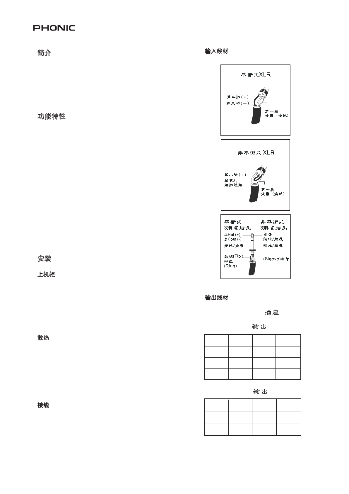
输入线材
安装
上机柜
XP功率放大器 可以 安装于标准的19英寸的机柜上。 此外 ,
还需要3U(5.25英寸)——XP2000/2100,XP3000/3100,和
XP5000/5100——或2U(3.5英寸)——XP600/XP1000——垂
直的支架空间。使用4个机柜螺丝和埋头垫圈将功放固定在
机柜上。在同一机柜上,最好将功放按照从下至上的顺序安
装,并确保两个功放间留有至少1U的空间,以提供有效的空
气流动和支撑。
散热
XP系列的两个变速散热风扇在开机的同时即开始运转。在功
放上机柜前,您首先需要熟悉此设备的散热系统。XP功放的
空气流通为从前往后,确保通风口不手阻塞是相当重要的。如
果功放已上机柜,应在支架前侧保留一定的空间以防止热空气
被再次吸入机器。气流受阻是散热不佳的主要原因,不恰当的
上机柜方式,捆绑的电线,滤灰器阻塞和机柜门未开都可能造
成空气流通受阻。上机柜时应确保空气可有效的从前侧通风口
排出,并在机身前后保留一定的空间以防止热空气回流。
接线
XP功放的平衡式XLR和TRS输入接头可连接大多数音响设备
的高电平输出。功放的内建XLR和TRS连接器可以在使用平
衡式或非平衡式,浮地或共地信号时用相似的接线方法连接。
输出接头为Speakon型的香蕉插头,可连接香蕉线头,平接线
头或裸线头
输出线材
18 XP 600/1000/2000/2100/3000/3100/5000/5100
Page 19

正面板功能说明
POWER
C
--3322
--1166
--1144
-6
0
10-
--2200--2200--22 00--2200
--4400--4400--44 00--4400
PROTECT
CLIP/
LIMI
T
NNOORRMMAALL
60
90
12
0
SUB
WOOFER
10-
--2200--2200--22 00--2200
--4400--4400--44 00--4400
--3322
--1166
--1144
6
0
PROTECT
CLIP/
LIMIT
NNOORRMMAALL
60
90
120
SUB
WOOFER
背板功能说明
1.峰值/限幅指示灯(红色)
当音频信号超出功放输出电路所能承载的范围时,即产生峰值
现象。限幅器在侦测到该现象的同时迅速减少增益从而降低超
载量,以尽可能的保持音乐的动态范围。
2.保护指示灯(黄色)
功放拥有多种保护电路,可在开机或故障时可保护设备,以免损
伤机器。开机延迟保护可在电源开启后有效的防止对音箱所造成
的损害。功放开启后,保护LED灯将持续闪亮数秒,然后熄灭,
即表示延迟保护已解除,已将音箱接通至功放。
音箱 接 线 端出现短路 , 或 音 箱与功放间 的 阻 抗 过低时,保 护
LED也会变亮。在这些情况下,保护LED灯将持续闪亮直至故
障得到修正。
若放大器的散热片因过热而发生故障,请继续向放大器通电,改善
通风并减少增益。在断电情况下,风扇无法工作,放大器需要更久
时间降温,直到可重新开机。
3.信号指示灯(绿色)
该功 率 放 大器的各输 入 声 道 均有用来显 示 输 入 信号强度的 指
示灯 . 指示灯的启 动 值是-4 0分贝。任 何 超 出这些强 度 的 噪音
都会启动相应 的指示灯。
4.增益控制
这两只旋钮可控制放大器各声道的音量.顺时针方向旋转可以增
加增益值.该旋钮具有制动设计。
5.电源开关
虽然本机有开/关静音功能,在开机前还是建议您将输入音量调到
最低,音响系统的正常开机顺序应该从乐器到调音台,在开启放大
器前应确保所有的系统运作正常。
6.重低音单元开关(仅适用于XP2100/XP3100/XP5100)
NORMAL/60/90/120Hz
从Normal切换至60Hz,90Hz或100Hz将会对 输出 信号进行低
通滤波,使得超低音输出可实现3音路或更多音路的音箱系统。
激活此功能后 ,您只能获 得低于60Hz,90Hz或120Hz的 超低
音输出。
7.运作状态显示
在通电状态下,前机身上方的PHONIC商标会呈绿色.当放大器
被切换至并联模式时,Logo旁边的LED将变成红色;并联模式
时LED指示灯呈黄色。
8.风扇
这两个温感变速风扇会自动维持本机内安全温度.由于冷空气从机
身后方进入前方然后流出,为了保持最佳空气流通,请确保前后通
风口的清洁畅通。
9.断路器复位
在使用额定负载和输出电平的情况下,断路器只有在极不常见的情
况下才会关闭放大器. 断路器也会在极低阻抗和高输出电平造成
超额电流的情况下关闭放大器.此功能不适用于XP600。
10.电源线
XP系列的电源线需要接通到合适的电源.该电源线是一条具有安全
功能的三缆接地式缆线.基于安全考虑,切勿对电源线作出任何改
动.请在连接插头前检查本地电压标准。
11.机壳接地点
为确保安全的接地方式,请在使用前参考您的区域安全法规。
12.输出连接器
该机 有一对通 用 的香蕉插 座 和一对speakon插 座 .这些插 座 为
各声 道 提 供 了多种连接 方 式 . 香蕉插头, 平接线 片 , 裸 线或
speakon插头都可以用来连接高音扬声器.为了避免发生短路,在
使用平接线片和裸线时,请务必将接线锁紧。1声道的speakon插
座为1声道,2声道和单声道桥接的针形插口提供了连接点.请参考
speakon插座旁的接线脚位说明表格。
13.输入接口
该机 为 了 方 便您接线特 地 提 供 了 XLR,TRS输入。XP5000和
XP5100还用有端子台输入。为了防止氧气进入连接处,在使用
端子台输入时, 请务必将接线锁紧. 端子台输入连接方式最适
合永久性联机。
14.共地/浮动开关
该开关可以在共地冲突的情况下将电路和机壳地位分开. 在正常
使用时, 应将它切换到共地方位. 提升共地位置(到浮动地位置)可
能会解决共地冲突的问题, 但也意味着电路的共地位置将由其它
相连接的设备决定. 其它构件的共地匮乏也会影响音质并造成地
回路交流哼声. 为了得到最佳的安全与性能组合, 建议您将此开
关设定到 “Grounding ON” 的位置。
19XP 600/1000/2000/2100/3000/3100/5000/5100
Page 20

15.限幅器开/关
此开关可将峰值限幅器电路指定至输入信号。可减少失真并保护音
箱。此开关不适用于XP5000和XP5100。
16.HPF
此开关 可 开 启 30Hz或 50Hz的高通 滤 波 器 , 切 除低 于 30Hz或
50Hz的信号。这样即可通过限制超低音信号的运动来加强重低音
效果。可增加音箱额定频率范围内的信号功率。此开关不适用于
XP5000或XP5100。
17.并联/立体声/桥接单声道模式开关
切换操作模式前,请务必关闭电源。立体声模式下,功放的各声道
均拥有各自的信号和音箱,独立运作。将开关设置于并联模式时,
CH2的输入将与CH1的输入并联。与此同时,CH1和CH2分别驱动
各自连接的音箱,但它们却共用相同的声源CH1。桥接单声道模式
下,两个声道即可以两倍功率的单一信号驱动单一的负载。请按照
以下的步骤从一种模式切换至另一种模式以确保系统的安全:
1、关闭功率放大器。
2、将一个负载至少为4欧姆的音箱连接至功放的红色(+)输出端。
3、确保只有一路输入信号连接至CH1。
4、将功放切换为桥接单声道模式。
5、将CH1和CH2的增益控制调节至最左端,然后打开功放。
6、确保开始操作时增益较低,然后逐步将CH1的增益增加至理想大小。
此开关不适用于XP5000或XP5100。
18. 操作模式开关 (仅适用于XP5000和XP5100)
这些开关(一声道的DIP开关1,2;二声道
的DIP开关11,12)可以启动能够衰减低
于30Hz或50Hz讯号的相应频率点高通滤
波器.超低音信号会因此受限,从而提高
了机器的性能.这也可以为扬声器的额定
频率范围提供更多可利用的功率。
这些DIP开关(一声道的DIP开关3和二声道的DIP开关10)使您
可以启用本机内建的波峰限制电路.这项功能可减少失真并
保护扬声器.如须启用内置限幅器,请将IP开关3(一声道限幅
器)和DIP开关10(二声道限幅器)切换到正确位置.
并联/立体声/单声道桥接
为避 免 损 坏您的XP调音 台 , 请在切换操 作 模 式前将电源 关
掉.4号,5号DIP开关使操作者可以在立体声和并联输入模式间
切换;而7号,8号DIP开关是用来启用单声道桥接模式.6号,9号
DIP开关分别用来启用并联和单声道桥接模式指示灯.
立体声模式
此操作
模式下,扩大机每一个声道的讯号和扬声器分别独立运
作.如须将扩大机转换至立体声模式,将DIP开关4,5,7和8切
换到左侧来切换模式并确认并联和单声道桥接模式指示灯被关
掉.每台音箱的阻抗在立体声模式下都应超过2ohms.
并联模式
此操作模式使一声 道的输入也
可以输入二声道 , 然 而 却 在 同
一信号源的情况 下 使 一 / 二 声
道的输出可以独立 的推动各自
的扬声器.如须 切 换 至 并 联 模
式, 将 DIP开关 4和 5切 换 到右
侧;而DIP开关7和8应被切换到
左侧 . 您也可以 将 DIP开 关 6切
换到 右 侧;DIP开关9切 换到左
侧来启用并联模式指示灯.每台
每台音箱的阻抗在 并联模式下
都应超过2ohms.
限幅器开关
单声道桥接模式
所 有 声 道 的 讯 号 被 合 并 后 传
送 到 单 声 道 桥 接 的 输 出 从 而
提 供 两 倍 的 输 出 功 率 . 二 声
道 的 增 益 控 制 应 设 置 到 最 低
值, 并应使用 一个额定 负载来顺 应更高的 输出功率 .如须切
换至单声道桥接模式,将DIP开关4,5,7,8和9切换到右侧;而
DIP开关6,10和11应被切换到左侧.您也可以将DIP开关9切换
到右侧;DIP开关6切换到左侧来启用单声道桥接模式指示灯.每
台音箱的阻抗在单声道桥接模式下都应超过4ohms.
20 XP 600/1000/2000/2100/3000/3100/5000/5100
Page 21

规格
XP 600 XP 1000 XP 2000 / XP 2100 XP 3000 / XP 3100
立体声模式(驱动两个声道)
8Ω 20Hz-20KHz 0.03% THD 125W 250W 400W 600W
4Ω 20Hz-20KHz 0.05% THD 200W 400W 600W 1000W
8Ω EIA 1KHz 1% THD 140W 275W 450W 650W
4Ω EIA 1KHz 1% THD 220W 440W 660W 1100W
2Ω EIA 1KHz 1% THD 280W 560W 960W 1400W
桥接单声道模式 连续平均输出功率
8Ω 20Hz-20KHz 0.1% THD 400W 800W 1200W 2000W
4Ω 1KHz 1% THD 560W 1120W 1920W 2800W
所有型号
输入灵敏度 @ 8Ω 1 Vrms 1.4 Vrms 1.73 Vrms
输入灵敏度 @ 4 Ω 0.9 Vrms 1.25 Vrms 1.23 Vrms 1.58 Vrms
噪音 (未加权 20Hz-20KHz低于额定
输出)
失真 (SMPTE-IM) <0.01% <0.02%
阻尼系数
输出电路
滤波器
重低音单体输出
频率响应
输入阻抗
散热
连接器 (各声道) 输入: XLR & 1/4”TRS 插孔 输出: Speakon & 香蕉插座
指示灯
前面板控制
功放保护
增益
功耗
尺寸(宽x高x深) 482.6 x 89 x 367.2mm
重量
电源: 琥珀色Phonic logo; 并联: 绿色背光图标; 桥接: 红色背光图标; 峰值/限幅: 红色LED; 保
CH1 & CH2 增益旋钮带 41段制动; 可选择低频分频器( 60Hz, 90Hz和 120Hz)
短路,过热,超低频,射频保护,输出DC补偿,散热片和变压器过热保护,电源开/关静音,平稳电源
150W 293W 880W 1460W
15kg (33lbs) 16kg (35.2lbs) 21kg (46.3lbs) 23.3kg (51.3lbs)
106 dB 107 dB
>200 @ 8Ω >500 @ 8Ω
重低音单体输出上可选择的重低音单体分频器(60Hz, 90Hz, 120Hz)
20Hz-20KHz, 0/-1dB, -3dB 点: 5Hz-100KHz
两个连续变速散热风扇,气流从前往后流动
护: 信号达到 -10dB, -20dB 和 -40dB时分别为黄色 LED和绿色 LED
32x (30dB) 40x (32dB)
19” x 3.5” x 14.4”
连续平均输出功率/声道
H级放大电路
高通滤波器(30Hz, 50Hz)
(仅适用于XP 2100, XP 3100)
20 kΩ平衡式, 10 kΩ 非平衡式
(仅适用于XP 2100 和 XP 3100 )
启动
482.6 x 133.5 x 376mm
19” x 5.25” x 14.8”
21XP 600/1000/2000/2100/3000/3100/5000/5100
Page 22

XP规格 XP5000/5100
立体声模式(推两声道)
8ohm 联邦贸易委员会20Hz-20KHz 0.1% 总协波失真 1050
4ohm 联邦贸易委员会20Hz-20KHz 0.1% 总协波失真 1600
2ohm 联邦贸易委员会20Hz-20KHz 0.1% 总协波失真 2000
8ohm 电子工业协会1KHz 0.1% 总协波失真 1100
4ohm 电子工业协会1KHz 0.1% 总协波失真 1800
2ohm 电子工业协会1KHz 1% 总协波失真 2500
单声道桥接模式 平均持续输出功率
8ohm 联邦贸易委员会20Hz-20KHz 0.1% 总协波失真 3200
8ohm 电子工业协会1KHz 0.1% 总协波失真 3600
4ohm 电子工业协会1KHz 1% 总协波失真 5000
全部机型
超低音输出
失真(美国电影电视工程师协会互调测试) <0.02%
失真(典型) 20Hz-20KHz: 低于额定功率10分贝 <0.02%
失真(典型) 20Hz-20KHz: 全额定功率 <0.02%
频率响应
阻尼系数
噪音(未加权)
输入灵敏度
正面控制
背面控制
电压增益
输入阻抗
指示灯
输入接口
输入接口
散热 持续温感变速风扇, 气流由后向前
扩大机保护 短路,开路,过热,超音波,射频保护. 可稳定失配负载
负载保护 开/关机静音, 直流输出补偿
输出线路
电源要求(因区域不同)
断路器
尺寸(宽x高x深)
凈重
可选性超低音切换:60Hz,90Hz,120Hz(仅供XP5100)
20Hz-20KHz, 8ohm,低通旁路滤波器, +0/-1分贝
5Hz-50KHz, 8ohm,低通旁路滤波器, +0/-3分贝
20Hz-20KHz, 8ohm负载: 低于额定输出100分贝
12极DIP开关: 高通滤波器开/关, 高通滤波器30/50Hz 限幅器
保护线跟按钮(每声道), 共地/浮动地滑动开关
(只供XP5100的可选性低通滤波器:60Hz,90Hz,120Hz)
开机: 橙红色PHONIC商标;
并联模式: 绿色背光符号
桥接模式: 红色背光符号
削波/限幅: 红色灯;
保护功能: 黄色灯 -10分贝,-20分贝,-40分贝
讯号水平:绿色灯
Speakon和香蕉插座(1声道为双功放系统接线)
100-120v交流电源, 200-240v交流电源(+/-10%),50/60Hz (厂商线
两组(每声道一组): 100-120v机型:20amp电流
482.6x133x415毫米 (19英寸x5.2英寸x16.3英寸)
每声道平均持续输出功率
>250@8ohm
100watts 8ohms:1.42vrms
AC电源开关, 1,2声道41齿止动式增益控制
开/关(每声道), 立体声模式,
并联模式, 桥接模式
41x(36分贝)
平衡式: 20k ohms, 非平衡式:10k ohms
XLR,1/4英吋TRS插座和阻挡带式接口
高效率H级扩大机
路设定); 120v机型需要20amp电流
230v机型:10amp电流
28.2公斤(62.1英磅)
22 XP 600/1000/2000/2100/3000/3100/5000/5100
Page 23

DIMENSIONS DIMENSIONES 尺寸
XP2000/2100/3000/3100
442.4/17.42
9
482.6/ 1
1
8
5
.
.
4
3
1
1
/
/
2
0
.
.
6
3
7
4
3
3
5
2
.
5
/
5
.
3
3
1
XP600/1000
442.4/17.42
482.6/ 19
5
4
.
.
3
4
1
1
/
/
0
2
.
.
3
7
4
6
3
3
5
.
3
/
9
8
measurements are shown in mm/inches
Todas las medidas están mostradas en mm/pulgadas.
尺寸是以毫米
mm/英寸inch
表示。
23XP 600/1000/2000/2100/3000/3100/5000/5100
Page 24

DIMENSIONS DIMENSIONES 尺寸
XP 5000 / 5100
measurements are shown in mm/inches
Todas las medidas están mostradas en mm/pulgadas.
尺寸是以毫米
mm/英寸inch
表示。
24 XP 600/1000/2000/2100/3000/3100/5000/5100
Page 25

BLOCK DIAGRAMS DIAGRAMAS DE BLOQUE 线路图
y
l
n
O
0
0
1
3
X
&
0
0
1
2
P
X p
y
l
n
O
0
0
1
3
X
&
0
0
1
2
P
X P
25XP 600/1000/2000/2100/3000/3100/5000/5100
Page 26

XP5000
26 XP 600/1000/2000/2100/3000/3100/5000/5100
Page 27

XP5100
27XP 600/1000/2000/2100/3000/3100/5000/5100
Page 28

support@phonic.com http://www.phonic.com
CÓMO COMPRAR EQUIPO ADICIONAL
Y ACCESORIOS DE PHONIC
Para comprar equipos y accesorios opcionales de
Phonic, póngase en contacto con cualquiera de los
distribuidores autorizados de Phonic. Para una lista
de los distribuidores de Phonic visite nuestra página
web en www.phonic.com y entre a la sección Get
Gear. También, puede ponerse en contacto directa
mente con Phonic y le ayudaremos a encontrar un
distribuidor cerca de usted.
SERVICIO Y REPARACIÓN
Para refacciones de reemplazo y reparaciones, por
favor póngase en contacto con nuestro distribuidor
de Phonic en su país. Phonic no distribuye manuales
de servicio directamente a los consumidores y, avisa
a los usuarios que no intenten hacer cualquier
reparación por si mismo, haciendo ésto invalidará
todas las garantías del equipo. Puede encontrar un
distribuidor cerca de usted en
http://www.phonic.com/where/.
INFORMACIÓN DE LA GARANTIA
Phonic respalda cada producto que hacemos con
una garantía sin enredo. La cobertura de garantía
podría ser ampliada dependiendo de su región.
Phonic Corporation garantiza este producto por un
mínimo de un año desde la fecha original de su
compra, contra defectos en materiales y mano de
obra bajo el uso que se instruya en el manual del
usuario. Phonic, a su propia opinión, reparará o
cambiará la unidad defectuosa que se encuentra
dentro de esta garantía. Por favor, guarde los recibos
de venta con la fecha de compra como evidencia de
la fecha de compra. Va a necesitar este comprobante
para cualquier servicio de garantía. No se aceptarán
reparaciones o devoluciones sin un número RMA
apropiado (return merchandise autorization). En
orden de tener esta garantía válida, el producto
deberá de haber sido manejado y utilizado como se
describe en las instrucciones que acompañan esta
garantía. Cualquier atentado hacia el producto o
cualquier intento de repararlo por usted mismo,
cancelará completamente esta garantía. Esta
garantía no cubre daños ocasionados por accidentes, mal uso, abuso o negligencia. Esta garantía es
válida solamente si el producto fue comprado nuevo
de un representante/distribuidor autorizado de
Phonic. Para la información completa acerca de la
política de garantía, por favor visite
http://www.phonic.com/warranty/.
SERVICIO AL CLIENTE Y SOPORTE
TÉCNICO
Le invitamos a que visite nuestro sistema de ayuda
en línea en www.phonic.com/support/. Ahí podrá
encontrar respuestas a las preguntas más frecuentes, consejos técnicos, descarga de drivers, instrucciones de devolución de equipos y más información
de mucho interés. Nosotros haremos todo el
esfuerzo para contestar sus preguntas lo antes
posible.
TO PURCHASE ADDITIONAL
PHONIC GEAR AND ACCESSORIES
To purchase Phonic gear and optional
accessories, contact any authorized
Phonic distributor. For a list of Phonic
distributors please visit our website at
www.phonic.com and click on Get Gear.
You may also contact Phonic directly and
we will assist you in locating a distributor
near you.
SERVICE AND REPAIR
For replacement parts, service and repairs
please contact the Phonic distributor in
your country. Phonic does not release
service manuals to consumers, and advice
users to not attempt any self repairs, as
doing so voids all warranties. You can
locate a dealer near you at
http://www.phonic.com/where/.
WARRANTY INFORMATION
Phonic stands behind every product we
make with a no-hassles warranty.
Warranty coverage may be extended,
depending on your region. Phonic Corpo
ration warrants this product for a minimum
of one year from the original date of
purchase against defects in material and
workmanship under use as instructed by
the user’s manual. Phonic, at its option,
shall repair or replace the defective unit
covered by this warranty. Please retain the
dated sales receipt as evidence of the date
of purchase. You will need it for any
warranty service. No returns or repairs will
be accepted without a proper RMA number
(return merchandise authorization). In
order to keep this warranty in effect, the
product must have been handled and used
as prescribed in the instructions accompa
nying this warranty. Any tempering of the
product or attempts of self repair voids all
warranty. This warranty does not cover
any damage due to accident, misuse,
abuse, or negligence. This warranty is
valid only if the product was purchased
new from an authorized Phonic
dealer/distributor. For complete warranty
policy information, please visit
http://www.phonic.com/warranty/.
CUSTOMER SERVICE AND
TECHNICAL SUPPORT
We encourage you to visit our online help
at http://www.phonic.com/support/. There
you can find answers to frequently asked
questions, tech tips, driver downloads,
returns instruction and other helpful
information. We make every effort to
answer your questions within one business
day.
购买 Phonic产 品及 其周边
器材
使用者如需购买Phonic产品及其周边
器材,请与Phonic授权的经销商取得
联 系 。 访 问 我 们 的 网 站
www.phonic.com,点击 Get Gear 即
可查 询 Phonic地 区经 销商 的联 系方
式。您也可直接联系Phonic公司,我
们将协助您快速定位离您最近的经销
商。
服务与维修
订购替换零件或维修事宜,请与您所
在地区的Phonic经销商联系。Phonic
不对使用者发行维修手册,且建议使
用者切勿擅自维修机器,否则将无法
获 得 任 何 保 固 服 务 。 您 可 登 录
http://www.phonic.com/where/定位离
您最近的经销商。
产品保固资讯
Phonic承诺对每项产品提供最完善的
保固服务。我们将根据客户群体所在
的地区来拓展我们的服务所涵盖的范
围。自原始购买日起,Phonic即对在
严格遵照使用说明书的操作规范下,
因产品材质和做工所产生的问题提供
至少 1年 的保固服 务。Phonic可在此
保固范围内任意地选择维修或更换缺
陷产品。请务必妥善保管购买产品的
凭证 , 以 此获 得 保 固服务 。 未 获得
RMA号的将不受理退货,以及保固服
务。保固服务只限于正常使用情况下
产生的问题。使用者需严格遵照使用
说明书正确使用,任何肆意损坏或擅
自维修机器,意外事故,错误使用,
人为 疏 忽 ,都 将 不 在保固 受 理 范围
内。此外,担保维修只限于在授权经
销商处的有效购买。欲知全部的保固
政 策 资 讯 , 请 参 考
http://www.phonic.com/warranty/。
客户服务和技术支持
欢 迎 您 访 问 我 们 的 网 站
http://www.phonic.com/support/。从
该网站上,您可获得各种常见问题的
答案 , 技 术指 导 , 并可下 载 产 品驱
动,获得有关退货指导以及其它帮助
资讯。我们竭尽全力在一个工作日内
回复您的询问。
 Loading...