

Page 1

Sensaphone STATIONSitter
User’s Manual
Version 1.21
PHONETICS, INC.
Page 2

Every effort has been made to ensure that the information in this
document is complete, accurate and up-to-date. Phonetics, Inc.
assumes no responsibility for the results of errors beyond its control.
Phonetics, Inc. also cannot guarantee that changes in equipment
made by other manufacturers, and referred to in this manual, will
not affect the applicability of the information in this manual.
Copyright © 2003 by Phonetics, Inc. dba
SENSAPHONE
®
First Edition, version 1.21, January, 2005
Written and produced by Phonetics, Inc.
Please address comments on this publication to:
Phonetics, Inc.
901 Tryens Road
Aston, PA 19014
Sensaphone is a registered trademark of Phonetics, Inc.
ii
Page 3

Important Safety Instructions
Your Sensaphone STATIONSitter has been carefully designed to give you years of
safe, reliable performance. As with all electrical equipment, however, there are a
few basic precautions you should take to avoid hurting yourself or damaging the
unit:
• Read the installation and operating instructions in this manual carefully. Be
sure to save it for future reference.
• Read and follow all warning and instruction labels on the product itself.
• To protect the Sensaphone STATIONSitter from overheating, make sure all
openings on the unit are not blocked. Do not place on or near a heat source,
such as a radiator or heat register.
• Do not use your Sensaphone STATIONSitter near water, or spill liquid of any
kind into it.
• Be certain that your power source matches the rating listed on the AC power
transformer. If you’re not sure of the type of power supply to your facility,
consult your dealer or local power company.
• Do not allow anything to rest on the power cord. Do not locate this product
where the cord will be abused by persons walking on it.
• Do not overload wall outlets and extension cords, as this can result in the risk
of fire or electric shock.
• Never push objects of any kind into this product through ventilation holes as
they may touch dangerous voltage points or short out parts that could result in
a risk of fire or electric shock.
• To reduce the risk of electric shock, do not disassemble this product, but
return it to Sensaphone Customer Service or another approved repair facility
when any service or repair work is required. Opening or removing covers may
expose you to dangerous voltages or other risks. Incorrect reassembly can
cause electric shock when the unit is subsequently used.
• If anything happens that indicates that your Sensaphone STATIONSitter is not
working properly or has been damaged, unplug it immediately and follow the
procedures in the manual for having it serviced. Return the unit for servicing
under the following conditions:
1. The power cord or plug is frayed or damaged.
2. Liquid has been spilled into the product or it has been exposed to water.
3. The unit has been dropped, or the enclosure is damaged.
4. The unit doesn’t function normally when you’re following the operating
instructions.
iii
Page 4

• Avoid using a telephone (other than a cordless type) during an electrical
storm. There may be a remote risk of electric shock from lightning.
• Do not use the telephone to report a gas leak in the vicinity of the leak.
CAUTION: To reduce the risk of fire or injury to persons, read and follow these
instructions:
1. Replace the battery only with the same or equivalent type recommended
by the manufacturer.
2. Do not dispose of the battery in a fire. The cell may explode. Check with
local codes for possible special disposal instructions.
3. Do not open or mutilate the battery. Released electrolyte is corrosive and
may cause damage to the eyes or skin. It may be toxic if swallowed.
4. Exercise care in handling battery in order not to short the battery with
conducting materials such as rings, bracelets, and keys. The battery or
conductor may overheat and cause burns.
iv
Page 5

FCC Requirements
Part 68: The Sensaphone STATIONSitter complies with 47 CFR, Part 68 of
the rules. On the back of the unit there is a label that contains, among other
information, the Certification Number and the Ringer Equivalence Number (REN)
for this equipment. You must, upon request, provide this information to your local
telephone company.
The REN is useful to determine the quantity of devices that you may connect to
your telephone line and still have all of those devices ring when your telephone
number is called. In most, but not all areas, the sum of the REN’s of all devices
connected to one line should not exceed f ive (5.0). To be certain of the number
of devices that you may connect to your line, you may want to contact your local
telephone company to determine the maximum REN for your calling area.
The applicable certification jack USOC for this equipment is: RJ11C. The facility
interface code (FIC) for this equipment is: 02LS2.
A compliant telephone cord and modular plug are provided with equipment. This
equipment is designated to be connected to the telephone network or premises
wiring using a compatible modular jack which is Part 68 compliant. See
Installation Instructions for details.
This equipment may not be used on coin service units provided by the telephone
company. Connection to party lines is subject to state tariffs. Contact the state
public utility commission, public service commission or corporation commission
for information.
Should the STATIONSitter cause harm to the telephone network, the telephone
company may discontinue your service temporarily. If possible, they will notify
you in advance. But if advance notice isn’t practical, the telephone company may
temporarily discontinue service without notice and you will be notified as soon as
possible. You will be informed of your right to file a complaint with the FCC. The
telephone company may make changes in its facilities, equipment, operations, or
procedures where such action is reasonably required in the operation of its business
and is not inconsistent with the rules and regulations of the FCC that could affect
the proper functioning of your equimenpt. If they do, you will be notified in
advance to give you an opportunity to maintain uninterrupted telephone service.
If you experience trouble with the STATIONSitter, or you need information on
obtaining service or repairs, please contact:
Phonetics, Inc.
901 Tryens Road
Aston, PA 19014
Toll-Free: 1-877-373-2700
FAX: 610-558-0222
v
Page 6

If the equipment is causing harm to the telephone network, the telephone company
may ask that you disconnect this equipment from the network until the problem has
been corrected or until you are sure that the equipment is not malfunctioning.
Part 15: This equipment has been tested and found to comply with the limits
for a Class A digital device, pursuant to Part 15 of the FCC Rules. These limits
are designed to provide reasonable protection against harmful interference
when the equipment is operated in a commercial environment. This equipment
generates, uses and can radiate radio frequency energy and, if not installed and
used in accordance with the instructions, may cause harmful interference to radio
communications. Operation of this equipment in a residential area is likely to
cause harmful interference in which case the user will be required to correct the
interference at his own expense.
General Requirements for all Automatic Dialers
When programming emergency numbers and (or) making test calls to emergency
numbers:
1. Remain on the line and briefly explain to the dispatcher the reason for the call.
2. Perform such activities in the off-peak hours, such as early morning or late
evenings.
vi
Page 7

Canadian Department of Communications Statement
Notice: The Canadian Department of Communications label identifies
certified equipment. This certification means that the equipment meets certain
telecommunications network protective operational and safety requirements. The
Department does not guarantee the equipment will operate to the user’s satisfaction.
Before installing this equipment, users should ensure that it is permissible to
be connected to the facilities of the local telecommunications company. The
equipment must also be installed using an acceptable method of connection. In
some cases, the company’s inside wiring associated with a single line individual
service may be extended by means of a certif ied connector assembly (telephone
extension cord). The customer should be aware that compliance with the above
conditions may not prevent degradation of service in some situations.
Repairs to certif ied equipment should be made by an authorized Canadian
maintenance facility designated by the supplier. Any repairs or alterations
made by the user to this equipment, or equipment malfunctions, may give
the telecommunications company cause to request the user to disconnect the
equipment.
Users should ensure for their own protection that the electrical ground connections
of the power utility, telephone lines and internal metallic water pipe system, if
present, are connected together. This precaution may be particularly important in
rural areas.
CAUTION: Users should not attempt to make such connec
tions themselves, but should contact the appropriate electric
inspection authority, or electrician, as appropriate.
-
The Ringer Equivalence Number (REN) assigned to each terminal device denotes
the percentage of the total load to be connected to a telephone loop which is used
by the device to prevent overloading. The termination on a loop may consist of
any combination of devices subject only to the requirement that the total of the
Ringer Equivalent Numbers of all the devices does not exceed 5.0. For Sensaphone
STATIONSitter, the AC Ringer Equivalent Number is 0.6B.
vii
Page 8

Sensaphone STATIONSitter Manual
viii
Page 9

3 YEAR LIMITED WARRANTY
PLEASE READ THIS WARRANTY CAREFULLY BEFORE USING THE
PRODUCT.
THIS LIMITED WARRANTY CONTAINS SENSAPHONE’S STANDARD
TERMS AND CONDITIONS. WHERE PERMITTED BY THE APPLICABLE
LAW, BY KEEPING YOUR SENSAPHONE PRODUCT BEYOND THIRTY
(30) DAYS AFTER THE DATE OF DELIVERY, YOU FULLY ACCEPT THE
TERMS AND CONDITIONS SET FORTH IN THIS LIMITED WARRANTY.
IN ADDITION, WHERE PERMITTED BY THE APPLICABLE LAW, YOUR
INSTALLATION AND/OR USE OF THE PRODUCT CONSTITUTES FULL
ACCEPTANCE OF THE TERMS AND CONDITIONS OF THIS LIMITED
WARRANTY (HEREINAFTER REFERRED TO AS "LIMITED WARRANTY
OR WARRANTY"). IF YOU DO NOT AGREE TO THE TERMS AND
CONDITIONS OF THIS WARRANTY, INCLUDING ANY LIMITATIONS OF
WARRANTY, INDEMNIFICATION TERMS OR LIMITATION OF LIABILITY,
THEN YOU SHOULD NOT USE THE PRODUCT AND SHOULD RETURN
IT TO THE SELLER FOR A REFUND OF THE PURCHASE PRICE. THE
LAW MAY VARY BY JURISDICTION AS TO THE APPLICABILITY OF YOUR
INSTALLATION OR USE ACTUALLY CONSTITUTING ACCEPTANCE OF
THE TERMS AND CONDITIONS HEREIN AND AS TO THE APPLICABILITY
OF ANY LIMITATION OF WARRANTY, INDEMNIFICATION TERMS OR
LIMITATIONS OF LIABILITY.
1. WARRANTOR: In this Warranty, Warrantor shall mean "Dealer,
Distributor, and/or Manufacturer."
2. ELEMENTS OF WARRANTY: This Product is warranted to be free
from defects in materials and craftsmanship with only the limitations and
exclusions set out below.
3. WARRANTY AND REMEDY: Three-Year Warranty — In the event that
the Product does not conform to this warranty at any time during the time
of three years from original purchase, warrantor will repair the defect and
return it to you at no charge.
This warranty shall terminate and be of no further effect at the time the
product is: (1) damaged by extraneous cause such as fire, water, lightning,
etc. or not maintained as reasonable and necessary; or (2) modified; or (3)
improperly installed; or (4) misused; or (5) repaired or serviced by someone
other than Warrantors’ authorized personnel or someone expressly
authorized by Warrantor’s to make such service or repairs; (6) used in a
manner or purpose for which the product was not intended; or (7) sold by
original purchaser.
LIMITED WARRANTY, LIMITATION OF DAMAGES AND DISCLAIMER
OF LIABILITY FOR DAMAGES: THE WARRANTOR’S OBLIGATION
ix
Page 10

Sensaphone STATIONSitter Manual
UNDER THIS WARRANTY IS LIMITED TO REPAIR OR REPLACEMENT
OF THE PRODUCT, AT THE WARRANTOR’S OPTION AS TO REPAIR
OR REPLACEMENT. IN NO EVENT SHALL WARRANTORS BE
LIABLE OR RESPONSIBLE FOR PAYMENT OF ANY INCIDENTAL,
CONSEQUENTIAL, SPECIAL AND/OR PUNITIVE DAMAGES OF
ANY KIND, INCLUDING BUT NOT LIMITED TO ANY LABOR COSTS,
PRODUCT COSTS, LOST REVENUE, BUSINESS INTERRUTPION
LOSSES, LOST PROFITS, LOSS OF BUSINESS, LOSS OF DATA
OR INFORMATION, OR FINANCIAL LOSS, FOR CLAIMS OF ANY
NATURE, INCLUDING BUT NOT LIMITED TO CLAIMS IN CONTRACT,
BREACH OF WARRANTY OR TORT, AND WHETHER OR NOT
CAUSED BY WARRANTORS’ NEGLIGENCE. IN THE EVENT THAT
IT IS DETERMINED IN ANY ADJUDICATION THAT THE LIMITED
WARRANTIES OF REPAIR OR REPLACEMENT ARE INAPPLICABLE,
THEN THE PURCHASER’S SOLE REMEDY SHALL BE PAYMENT TO
THE PURCHASER OF THE ORIGINAL COST OF THE PRODUCT, AND IN
NO EVENT SHALL WARRANTORS BE LIABLE OR RESPONSIBLE FOR
PAYMENT OF ANY INCIDENTAL, CONSEQUENTIAL, SPECIAL AND/OR
PUNITIVE DAMAGES OF ANY KIND, INCLUDING BUT NOT LIMITED
TO ANY LOST REVENUE, BUSINESS INTERRUTPION LOSSES, LOST
PROFITS, LOSS OF BUSINESS, LOSS OF DATA OR INFORMATION, OR
FINANCIAL LOSS, FOR CLAIMS OF ANY NATURE, INCLUDING BUT
NOT LIMITED TO CLAIMS IN CONTRACT, BREACH OF WARRANTY
OR TORT, AND WHETHER OR NOT CAUSED BY WARRANTORS’
NEGLIGENCE.
WITHOUT WAIVING ANY PROVISION IN THIS LIMITED WARRANTY,
IF A CIRCUMSTANCE ARISES WHERE WARRANTORS ARE FOUND
TO BE LIABLE FOR ANY LOSS OR DAMAGE ARISING OUT OF
MISTAKES, NEGLIGENCE, OMISSIONS, INTERRUPTIONS, DELAYS,
ERRORS OR DEFECTS IN WARRANTORS’ PRODUCTS OR SERVICES,
SUCH LIABILITY SHALL NOT EXCEED THE TOTAL AMOUNT PAID BY
THE CUSTOMER FOR WARRANTORS’ PRODUCT AND SERVICES
OR $250.00, WHICHEVER IS GREATER. YOU HEREBY RELEASE
WARRANTORS FROM ANY AND ALL OBLIGATIONS, LIABILITIES AND
CLAIMS IN EXCESS OF THIS LIMITATION.
INDEMNIFICATION AND COVENANT NOT TO SUE: YOU WILL
INDEMNIFY, DEFEND AND HOLD HARMLESS WARRANTORS,
THEIR OWNERS, DIRECTORS, OFFICERS, EMPLOYEES, AGENTS,
SUPPLIERS OR AFFILIATED COMPANIES, AGAINST ANY AND ALL
CLAIMS, DEMANDS OR ACTIONS BASED UPON ANY LOSSES,
LIABILITIES, DAMAGES OR COSTS, INCLUDING BUT NOT LIMITED TO
DAMAGES THAT ARE DIRECT OR INDIRECT, INCIDENTAL, SPECIAL OR
CONSEQUENTIAL, AND INCLUDING ATTORNEYS FEES AND LEGAL
COSTS, THAT MAY RESULT FROM THE INSTALLATION, OPERATION,
USE OF, OR INABILITY TO USE WARRANTORS’ PRODUCTS AND
SERVICES, OR FROM THE FAILURE OF THE WARRANTORS’ SYSTEM
x
Page 11

TO REPORT A GIVEN EVENT OR CONDITION, WHETHER OR NOT
CAUSED BY WARRANTORS’ NEGLIGENCE.
YOU AGREE TO RELEASE, WAIVE, DISCHARGE AND COVENANT NOT
TO SUE WARRANTORS, THEIR OWNERS, DIRECTORS, OFFICERS,
EMPLOYEES, AGENTS, SUPPLIERS OR AFFILIATED COMPANIES,
FOR ANY AND ALL LIABILITIES POTENTIALLY ARISING FROM ANY
CLAIM, DEMAND OR ACTION BASED UPON ANY LOSSES, LIABILITIES,
DAMAGES OR COSTS, INCLUDING BUT NOT LIMITED TO DAMAGES
THAT ARE DIRECT OR INDIRECT, INCIDENTAL, SPECIAL OR
CONSEQUENTIAL, AND INCLUDING ATTORNEYS FEES AND LEGAL
COSTS, THAT MAY RESULT FROM THE INSTALLATION, OPERATION,
USE OF, OR INABILITY TO USE WARRANTORS’ PRODUCTS AND
SERVICES, OR FROM THE FAILURE OF THE WARRANTORS’ SYSTEM
TO REPORT A GIVEN EVENT OR CONDITION, WHETHER OR NOT
CAUSED BY WARRANTORS’ NEGLIGENCE, EXCEPT AS NECESSARY
TO ENFORCE THE EXPRESS TERMS OF THIS LIMITED WARRANTY.
EXCLUSIVE WARRANTY: THE LIMITED WARRANTY OR WARRANTIES
DESCRIBED HEREIN CONSTITUTE THE SOLE WARRANTY OR
WARRANTIES TO THE PURCHASER. ALL IMPLIED WARRANTIES
ARE EXPRESSLY DISCLAIMED, INCLUDING: THE WARRANTY
OF MERCHANTIBILITY AND THE WARRANTY OF FITNESS
FOR A PARTICULAR USE AND THE WARRANTY OF FITNESS
FOR A PARTICULAR PURPOSE AND THE WARRANTY OF NONINFRINGEMENT AND/OR ANY WARRANTY ARISING FROM A COURSE
OF DEALING, USAGE, OR TRADE PRACTICE.
It must be clear that the Warrantors are not insuring your premises or
business or guaranteeing that there will not be damage to your person or
property or business if you use this Product. You should maintain insurance
coverage sufficient to provide compensation for any loss, damage, or
expense that may arise in connection with the use of products or services,
even if caused by Warrantors’ negligence. The warrantors assume no
liability for installation of the Product and/or interruptions of the service due
to strikes, riots, floods, fire, and/or any cause beyond Seller’s control, further
subject to the limitations expressed in any License Agreement or other
Agreement provided by Warrantors to purchaser.
The agreement between the Warrantors and the Purchaser, including but
not limited to the terms and conditions herein shall not be governed by
the Convention for the International Sale of Goods. Where applicable, the
Uniform Commercial Code as adopted by the State of Delaware shall apply.
4. PROCEDURE FOR OBTAINING PERFORMANCE OF WARRANTY: In
the event that the Product does not conform to this warranty, the Product
should be shipped or delivered freight prepaid to a Warrantor with evidence
of original purchase.
xi
Page 12

Sensaphone STATIONSitter Manual
5. LEGAL REMEDIES AND DISCLAIMER: Some jurisdictions may
not allow, or may place limits upon, the exclusion and/or limitation of
implied warranties, incidental damages and/or consequential damages
for some types of goods or products sold to consumers and/or the use
of indemnification terms. Thus, the exclusions, indemnification terms
and limitations set out above may not apply, or may be limited in their
application, to you. If the implied warranties can not be excluded, and
the applicable law permits limiting the duration of implied warranties,
then the implied warranties herein are to be limited to the same duration
as the applicable written warranty or warranties herein. The warranty or
warranties herein may give you specific legal rights that will depend upon
the applicable law. You may also have other legal rights depending upon
the law in your jurisdiction.
6. CHOICE OF FORUM AND CHOICE OF LAW: In the event that a
dispute arises out of or in connection with this Limited Warranty, then
any claims or suits of any kind concerning such disputes shall only and
exclusively be brought in either the Court of Common Pleas of Delaware
County, Pennsylvania or the United States District Court for the Eastern
District of Pennsylvania.
Regardless of the place of contracting or performance, this Limited
Warranty and all questions relating to its validity, interpretation, performance
and enforcement shall be governed by and construed in accordance
with the laws of the State of Delaware, without regard to the principles of
conflicts of law.
Effective date 05/01/2004
PHONETICS, INC. d.b.a. SENSAPHONE
901 Tryens Road
Aston, PA 19014
Phone: 610.558.2700 Fax: 610.558.0222
www.sensaphone.com
xii
Page 13

Table of Contents
Table of Contents
Important Safety Instructions. . . . . . . . . . . . . . . . . . . . . . .iii
FCC Requirements . . . . . . . . . . . . . . . . . . . . . . . . . . . . .
Canadian Department of Communications Statement
. . . vii
v
Warranty
. . . . . . . . . . . . . . . . . . . . . . . . . . . . . . . . . . . . .ix
Chapter 1: Introduction. . . . . . . . . . . . . . . . . . . 17
FEATURES. . . . . . . . . . . . . . . . . . . . . . . . . . . . . . . . . . . 18
LAYOUT
TECHNICAL SUPPORT . . . . . . . . . . . . . . . . . . . . . . . . . .
. . . . . . . . . . . . . . . . . . . . . . . . . . . . . . . . . . . . 19
20
Chapter 2: Installation . . . . . . . . . . . . . . . . . . . 21
OPERATING ENVIRONMENT . . . . . . . . . . . . . . . . . . . . . 21
Mounting the STATIONSitter
Grounding . . . . . . . . . . . . . . . . . . . . . . . . . . . . . . 22
TURNING THE STATIONSITTER ON
Backup Battery (optional)
Telephone Line . . . . . . . . . . . . . . . . . . . . . . . . . . .
WIRING SENSORS & TRANSDUCERS TO ZONE INPUTS . . 24
Wiring Recommendations . . . . . . . . . . . . . . . . . . .
LED INDICATORS . . . . . . . . . . . . . . . . . . . . . . . . . . . . .
. . . . . . . . . . . . . . . . . . 21
. . . . . . . . . . . . . . . . . 23
. . . . . . . . . . . . . . . . . . . . 23
24
26
27
Chapter 3: Getting Started . . . . . . . . . . . . . . . . 29
HOW THE KEYPAD COMMANDS WORK . . . . . . . . . . . . 29
ABORTING A COMMAND
ERROR MESSAGES . . . . . . . . . . . . . . . . . . . . . . . . . . . .
ACKNOWLEDGING A FALSE ALARM
RECOMMENDED PROGRAMMING STEPS
. . . . . . . . . . . . . . . . . . . . . . . 29
29
. . . . . . . . . . . . . . . 30
. . . . . . . . . . . . 30
Chapter 4: Zone Programming . . . . . . . . . . . . . 31
CONFIGURE ZONE TYPE. . . . . . . . . . . . . . . . . . . . . . . . 31
MANUAL ZONE CONFIGURATION . . . . . . . . . . . . . . . .
ENABLE/DISABLE ZONE ALARMS . . . . . . . . . . . . . . . . .
ENABLE/DISABLE SOUND LEVEL ALARM . . . . . . . . . . . .
ENABLE/DISABLE POWER
. . . . . . . . . . . . . . . . . . . . . . . 34
32
33
34
xiii
Page 14

Sensaphone STATIONSitter Manual
CONFIGURE TEMPERATURE SCALE . . . . . . . . . . . . . . . . 35
CONFIGURE TABLE RANGE FOR 4-20mA SENSORS
. . . . 35
ALARM RECOGNITION TIME . . . . . . . . . . . . . . . . . . . . . 38
ALARM LIMITS . . . . . . . . . . . . . . . . . . . . . . . . . . . . . . .
ZONE CALIBRATION
SOUND LEVEL CALIBRATION
DESIGNATING A ZONE AS UNUSED
EXIT DELAY
. . . . . . . . . . . . . . . . . . . . . . . . . . . . . . . . . . 49
. . . . . . . . . . . . . . . . . . . . . . . . . . . 44
. . . . . . . . . . . . . . . . . . . . . 46
. . . . . . . . . . . . . . . 48
41
Chapter 5: Communication Programming . . . . . 51
DATE and TIME. . . . . . . . . . . . . . . . . . . . . . . . . . . . . . . 51
VOICE MESSAGES . . . . . . . . . . . . . . . . . . . . . . . . . . . .
ID NUMBER . . . . . . . . . . . . . . . . . . . . . . . . . . . . . . . . .
ALARM DIAL-OUT TELEPHONE NUMBERS . . . . . . . . . . .
Voice Dialout . . . . . . . . . . . . . . . . . . . . . . . . . . . .
Numeric Pager Dialout . . . . . . . . . . . . . . . . . . . . .
Alphanumeric Pager Dialout
. . . . . . . . . . . . . . . . . . 63
SPECIAL DIALING OPTIONS . . . . . . . . . . . . . . . . . . . . .
Blind Dialing . . . . . . . . . . . . . . . . . . . . . . . . . . . .
DIAL-OUT TEST MODE
. . . . . . . . . . . . . . . . . . . . . . . . . . 69
ALARM ACKNOWLEDGMENT CODES . . . . . . . . . . . . . .
ALARM HISTORY . . . . . . . . . . . . . . . . . . . . . . . . . . . . .
Deleting the Alarm History
TONE OR PULSE DIALING
RINGS UNTIL ANSWER
. . . . . . . . . . . . . . . . . . . . . . . . . 74
. . . . . . . . . . . . . . . . . . . 72
. . . . . . . . . . . . . . . . . . . . . . . 73
CALL DELAY TIME . . . . . . . . . . . . . . . . . . . . . . . . . . . . .
INTERCALL TIME
CALL PROGRESS
. . . . . . . . . . . . . . . . . . . . . . . . . . . . . . 77
. . . . . . . . . . . . . . . . . . . . . . . . . . . . . . 79
VOICE REPETITIONS . . . . . . . . . . . . . . . . . . . . . . . . . . .
MAX CALLS . . . . . . . . . . . . . . . . . . . . . . . . . . . . . . . . .
TELEPHONE ANSWERING DEVICE (TAD) COMPATIBILITY
LISTEN-IN TIME
LOCKING THE KEYPAD
. . . . . . . . . . . . . . . . . . . . . . . . . . . . . . . 84
. . . . . . . . . . . . . . . . . . . . . . . . . 85
SPEAKER MUTE . . . . . . . . . . . . . . . . . . . . . . . . . . . . . .
CALLBACK ACKNOWLEDGMENT
xiv
. . . . . . . . . . . . . . . . . . 88
53
56
58
58
60
67
68
70
72
75
80
81
83
87
Page 15

Table of Contents
Chapter 6: Pump Control . . . . . . . . . . . . . . . . . 89
Output Wiring . . . . . . . . . . . . . . . . . . . . . . . . . . . . . . . 89
Level Sensor or Float Switch Selection
Analog Level Sensor Wiring . . . . . . . . . . . . . . . . . . . . .
Float Switch Wiring for Draining the Well
Float Switch Wiring for Filling the Well . . . . . . . . . . . . .
Installation Recommendations
Pump Control Programming . . . . . . . . . . . . . . . . . . . . .
Analog Level Sensor Programming . . . . . . . . . . . . . . . .
Programming the Pump Control Mode
Float Switch Programming . . . . . . . . . . . . . . . . . . . . . .
Manually Controlling the Pump Outputs . . . . . . . . . . . .
Application Example
. . . . . . . . . . . . . . . . . . . . . . . . . . 100
. . . . . . . . . . . . . . . . . . . . 93
. . . . . . . . . . . . . . 90
91
. . . . . . . . . . . 91
92
93
93
. . . . . . . . . . . 95
97
99
Chapter 7: Controlling the Auxiliary Output . . 101
AUTOMATIC MODES. . . . . . . . . . . . . . . . . . . . . . . . . . 101
MANUAL MODE . . . . . . . . . . . . . . . . . . . . . . . . . . . . . 102
Manually Switching the Auxiliary Output
. . . . . . . . 102
Chapter 8: Internet Web Status . . . . . . . . . . . . 105
Chapter 9: Operation
ALARM DIALOUT AND ACKNOWLEDGMENT. . . . . . . . 107
Alarm Recognition
Alarm Notification
Dialout Note: Call Progress . . . . . . . . . . . . . . . . .
Alarm Dialout—Voice . . . . . . . . . . . . . . . . . . . . .
Alarm Dialout - Pager . . . . . . . . . . . . . . . . . . . . .
Alarm Dialout - Alphanumeric Pager
ALARM ACKNOWLEDGMENT . . . . . . . . . . . . . . . . . . .
Voice Dialout . . . . . . . . . . . . . . . . . . . . . . . . . . .
Numeric Pager Dialout . . . . . . . . . . . . . . . . . . . .
Alphanumeric Pager Dialout
Automatic (Max Calls)
CALL-IN STATUS . . . . . . . . . . . . . . . . . . . . . . . . . . . . .
REMOTE COMMANDS VIA TOUCH-TONE PHONE . . . .
. . . . . . . . . . . . . . . . . . . 107
. . . . . . . . . . . . . . . . . . . . . . . . 107
. . . . . . . . . . . . . . . . . . . . . . . . 107
107
107
108
. . . . . . . . . . . 108
109
109
110
. . . . . . . . . . . . . . . . . 111
. . . . . . . . . . . . . . . . . . . . . 112
113
114
xv
Page 16

Sensaphone STATIONSitter Manual
APPENDIX A: Checking Your STATIONSitter for
Proper Operation . . . . . . . . . . . 119
APPENDIX B: Troubleshooting STATIONSitter . .
APPENDIX C: 2.8K & 10K Thermistor Tables . .
APPENDIX D: Technical Specifications . . . . . . .
APPENDIX E: Quick Reference Guide
APPENDIX F:
Accessories . . . . . . . . . . . . . . . . 139
. . . . . . . . 135
Test Log . . . . . . . . . . . . . . . . . . . . . . . . . . . . .
121
131
133
141
Index . . . . . . . . . . . . . . . . . . . . . . . . . . . . . . . 143
xvi
Page 17

Chapter 1: Introduction
CHAPTER 1: INTRODUCTION
Congratulations on your purchase of the Sensaphone
STATIONSitter. The STATIONSitter is a powerful integrated pump
controller and alarm dialer. The STATIONSitter can perform duplex
pump control using either a level transducer or float switches for fill
or drain applications. It can monitor equipment and environmental
conditions using eight universal Zones, built-in power failure
detection, and sound level monitoring. The Sensaphone
STATIONSitter also features several communication options: userrecordable voice, numeric pager, and alphanumeric pager (wireless
phone text message). The STATIONSitter can also produce a web
page of pump and zone status and alarm history, using our optional
service. The STATIONSitter is the ultimate choice for pump station
control or similar monitoring applications.
The Sensaphone STATIONSitter is a fully programmable
environmental monitoring system for unattended or remote
applications. The unit will monitor and alarm on eight zones: N.O./
N.C.(Normally Open or Normally Closed) contact, 2.8K and 10K
thermistor (temperature sensor), and 4-20mA transducer. The unit
will also monitor AC power, sound level, and battery condition. On
the front of the unit are LED indicators to show the operating status.
Each zone (including power, sound and battery) has a status LED
indicating the alarm status of the Zone. There is also an LED to
indicate if the Output is On, an LED for Phone In-Use status and an
LED for System-On status.
The unit is programmed using the built-in keypad and voice
response menus. All programming is stored in nonvolatile memory
so that all programming is retained even without power. The unit
is capable of performing alarm event logging of the eight universal
Zones, power, and sound. The event logging (history) is also stored
in nonvolatile memory. A battery-backed real-time clock is also
included to time-stamp logged events. The alarm event history
can be heard through the built-in speaker or remotely over the
telephone. A complete status report of all monitored conditions can
also be heard simply by calling the STATIONSitter. An optional web
page can be periodically updated to allow viewing STATIONSitter
status from any internet-connected computer.
17
Page 18

Sensaphone STATIONSitter Manual
The unit comes in an aluminum enclosure with tabs for wall or
panel mounting. Terminal connections for Zones, outputs and power
are easily accessible from the front of the unit. The STATIONSitter
is powered by a plug-in adapter and has connections for an optional
12V rechargeable backup battery. Circuitry in the unit will maintain
precise charging of the battery system.
FEATURES
The Sensaphone STATIONSitter Includes the following features:
Eight Zones configurable as temperature, 4-20mA or dry
contact
Calibration for each each Zone
Each Zone can be individually enabled or disabled
Power monitor
High sound-level monitor (w/optional external mic)
1 auxiliary relay output (manual or automatic control)
2 pump control relay outputs
17 status LEDs
Dial out to eight telephone numbers
User-recordable voice messages
Alarm dialout via voice, numeric pager and
alphanumeric pager (wireless phone text message)
Microphone for on-site listen-in (w/optional external mic
Line Seizure to ensure reliable alarm delivery
Time-stamped Alarm History
Optional web page
Superior surge/lightning protection on all Zones, telephone
line and power supply
12-hour rechargeable battery backup (optional)
Duplex pump controller using either a level transducer or
float switches for fill or drain applications.
Isolated 24VDC power supply for powering level transducer.
Optically isolated inputs for pump control.
18
Page 19
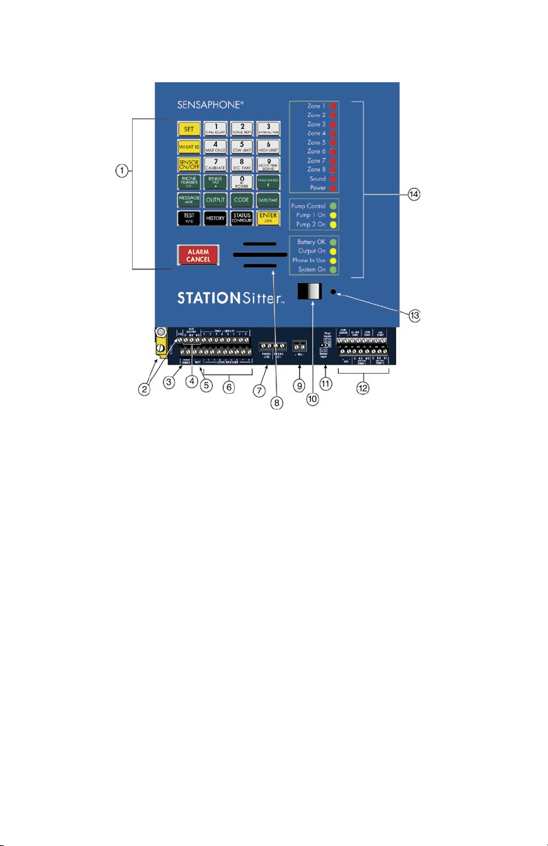
LAYOUT
Chapter 1: Introduction
1. Keypad
2. Earth Grounds
3. 12VAC terminal
4. Auxiliary Output terminals
5. Battery terminal
6. Zone Input/Ground terminals
Figure 1: STATIONSitter diagram
7. Phone terminals
8. Speaker
9. External Microphone terminal
10. Power switch
11. Sensor/Float Control jumpers
12. Pump Control Terminal Block
13. Built-in microphone
14. System LEDs
19
Page 20

Sensaphone STATIONSitter Manual
TECHNICAL SUPPORT
Reading this instruction manual will help you install and program
STATIONSitter easily. Programming and voice recording are
performed locally using the built-in keypad. Some programming
can also be accessed via touch-tone phone.
If there are any questions or problems that arise upon installation or
operation, please contact Technical Support at:
PHONETICS, INC.
901 Tryens Road
Aston, PA 19014
Toll-Free Phone: 1-877-373-2700
FAX: 610-558-0222
[email protected]
20
Page 21
Chapter 2: Installation
CHAPTER 2: INSTALLATION
OPERATING ENVIRONMENT
The Sensaphone STATIONSitter should be mounted and operated
in a clean, dry environment. The unit is microprocessor-controlled
and as a result it should not be installed near devices that generate
strong electromagnetic fields. Such interference is typically
generated by power switching equipment such as relays or
contactors. A poor operating environment may result in unwanted
system resets and/or system lockup. The temperature range the unit
can operate in is 32°F to 122°F (0°C to 50°C). If the unit needs to
operate below freezing, a heater should be installed nearby.
Mounting the STATIONSitter
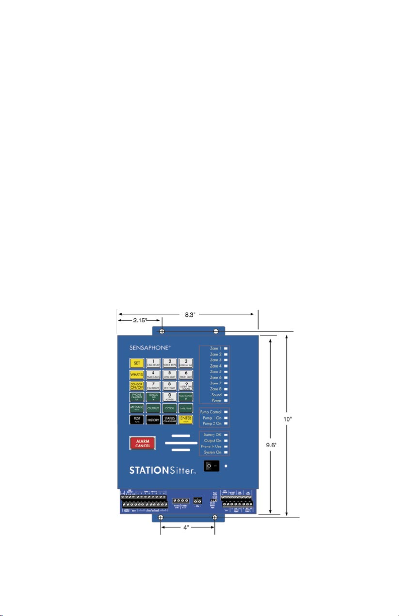
The STATIONSitter comes with hardware for wall or panel
mounting.Mount the unit in a position that allows easy access to the
terminal blocks and keypad. Also, there must be a power outlet and
telephone jack close to the unit.
Figure 1: Mounting Dimensions
21
Page 22
Sensaphone STATIONSitter Manual
Grounding
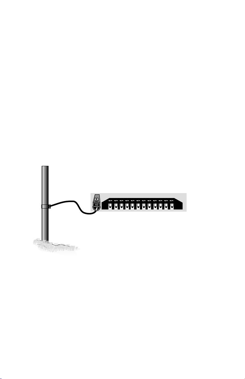
Connect a heavy gauge (#10AWG) copper wire to the earth ground
lug on the left end of the panel and connect the other end to a
ground rod or metal cold water pipe (See Figure 3). It is extremely
important that the earth ground connection be as short as possible.
The ground rod should have sufficient depth to provide a low
impedance connection to earth. This connection is required for the
surge/lightning protection circuits to function properly.
NOTE: Proper earth grounding of the
STATIONSitter is required for warranty coverage.
Ground rods can typically be found at local electrical supply houses
and/or hardware stores. Be sure to contact your state “Call before
you dig” hotline at least two days before you install your ground
rod, to insure that it is safe to install the ground rod in a chosen
area.
Figure 3: Grounding the STATIONSitter
22
Page 23
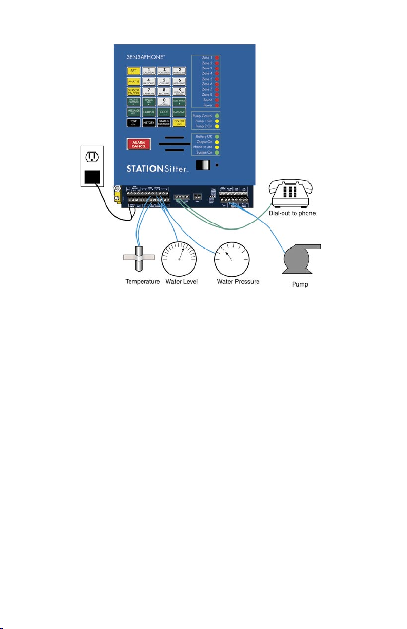
Figure 4: Typical connections from STATIONSitter
Chapter 2: Installation
TURNING THE STATIONSITTER ON
Plug the unit’s transformer into a 120VAC 60Hz outlet. Toggle the
power switch to ON to start the unit. The System-On LED should
glow steadily and the unit will say “Hello.”
Note that when the unit is turned off, all programming is retained in
non-volatile memory.
Backup Battery (optional)
The Sensaphone STATIONSitter includes for connecting a 12V
sealed lead-acid gel-cell rechargeable battery for system back-up in
the event of a power failure. The battery will provide approximately
12 hours of backup time. Actual backup time will depend upon the
temperature, battery age, and dialing activity.
The STATIONSitter will automatically charge the battery whenever
the power switch is turned on and the power transformer is plugged
in. The unit also includes special circuitry to prevent the battery
23
Page 24

Sensaphone STATIONSitter Manual
from being damaged in the event of an extended power outage.
The battery should provide about 5 years of service before needing
replacement. See Appendix B for battery replacement instructions.
The STATIONSitter also includes a 3V lithium battery to retain the
date and time when main power is off. The lithium battery should
provide 8-10 years of service life.
NOTE: Have batteries serviced by qualified service
personnel only.
Telephone Line
Connect the STATIONSitter’s Phone jack to a standard 2-wire
analog phone line. The unit dials using pulse or tone, with loop start
only. The STATIONSitter will recognize ringer frequencies from
16 to 60 Hz and will operate with all standard analog telephone
systems that accept pulse or tone dialing.
Certain private telephone systems and public switching equipment
may not accept the unit’s dialing or may generate an unacceptable
ring signal. In those cases, a dedicated line may be required for the
unit. Consult the supplier of your telephone system if you encounter
problems.
CAUTION: Never install telephone wiring during a
lightning storm. Never install telephone jacks in wet
locations unless the jack is specifically designed for
wet locations. Never touch uninsulated telephone wires
or terminals unless the telephone line has been dis
connected at the network interface. Use caution when
installing or modifying telephone lines.
WIRING SENSORS AND TRANSDUCERS TO ZONE INPUTS
The STATIONSitter Zones are compatible with NO/NC dry
contacts, 2.8K and 10K thermistors, and 4-20mA transducers. To
prevent an alarm from occurring while wiring the sensors, it is
recommended that the zone be disabled [SENSOR ON/OFF] +
[Zone #1-8]. After wiring all of your sensors you will need to
configure the zones using the [SET] + [CONFIGURE] command.
See Chapter 3 for more information on Disabling sensors and
Configuring Zones.
24
Page 25

Chapter 2: Installation
Recommended sequence for adding a new sensor:
1. Disable the zone.
2. Wire up the sensor.
3. Configure the zone.
4. Enable the zone.
Note: If a false alarm occurs while wiring a sensor, you can quickly acknowledge it by pressing
the [ALARM/CANCEL] key and entering [11234]
+ [ENTER]. This is the default acknowledgment
code for user #1. See Chapter 4 for more informa
-
tion on User Acknowledgment Codes.
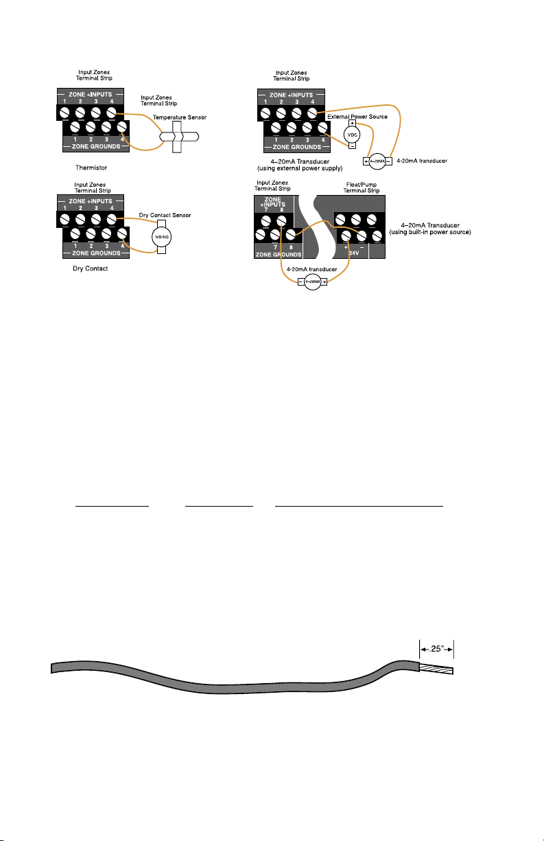
Temperature: The unit will accept 10K thermistors. These should
be wired to a Zone terminal and the adjacent ground terminal. For
compatible thermistors check the accessory list or thermistor data in
the appendices. 10K Thermistor temperature range: -20ºF to 150ºF
(-29ºC to 65ºC).
Dry Contacts: Only contacts which have no voltage or current
applied may be used. Connect the contact to a Zone terminal and
an adjacent ground terminal. Do NOT try to monitor a contact that
switches 120VAC. This will permanently damage the unit.
4–20mA: A 4–20mA transducer typically requires you to have an
external DC power supply for the transducer to operate. On the
Pump Control terminal strip is an isolated 24V DC supply which
can be used for this purpose; however, it can only provide enough
current for up to 2 transducers. An external supply has to be used in
order to power additional transducers. When wiring the transducer,
connect the positive wire of your transducer to the positive terminal
of your DC power supply. Connect the negative terminal of the
transducer to a Zone (
+) input terminal on the StationSitter. Connect
the negative terminal from your power supply to the adjacent Zone
ground terminal on the StationSitter.
25
Page 26
Sensaphone STATIONSitter Manual
Figure 5: Different Sensor Types connected to the Terminal Block
Wiring Recommendations
The STATIONSitter will work fine in indoor environments using
unshielded cable. When wiring will be subject to long lengths
(>250') or if run outdoors, it is highly recommended that shielded
cable be used and that the shield be connected to an earth ground.
Also, be sure to use the appropriate gauge wire based on the
distance and sensor type. See chart below:
Wire Gauge
Thermistor NO/NC Contact & 4-20mA
#24 250' 1000'
#22 500' 2000'
#20 1000' 4000'
When preparing wire for connection to the terminal blocks, strip
1/4" of insulation from the conductor (see figure below).
Figure 6: Wire stripped for connection
26
Page 27

LED INDICATORS
The LEDs provide on-site alarm and status information. Listed
below are descriptions of how the LEDs work.
Zones 1–8, Sound and Power:
LED Off: Zone OK
LED Blinking Fast: Alarm condition exists but
recognition time has not been met
LED Blinking Slowly: Unacknowledged alarm exists
LED On: Acknowledged alarm exists
Pump Control:
LED On: Pump Control is on
Pump 1 On:
LED On: Pump 1 is on
Pump 2 On:
LED On: Pump 2 is on
Battery OK:
Chapter 2: Installation
LED On: Battery OK
LED Blinking: Battery condition low
Output On:
LED On: Auxiliary output relay on
LED Off : Auxiliary output relay off
Phone-In-Use:
LED On: Unit is communicating on the phone line
LED Off: Unit is not using the phone line
System-On:
LED On: System power on
LED Off : System power off
27
Page 28

Sensaphone STATIONSitter Manual
28
Page 29

Chapter 3: Getting Started
CHAPTER 3: GETTING STARTED
This section presents a brief guide and some helpful hints for
first-time users of the STATIONSitter. Follow the instructions for
installation before attempting to program the unit.
HOW THE KEYPAD COMMANDS WORK
The STATIONSitter uses simple keypad commands to program
and listen to all pertinent parameters. All of the keypad commands
begin with either the SET, WHAT IS, or SENSOR ON/OFF keys.
The SET key is used to program parameters. When performing a
programming sequence, the command will typically require the
SET key followed by the parameter to be programmed, followed
by a value, and then the ENTER key at the end. For example, to
program the Call Delay you would press [SET] + [CALL DELAY]
+ [value] + [ENTER]. To check your programming , you would
press the WHAT IS key followed by the parameter (in this case,
[WHAT IS] + [CALL DELAY].
The SENSOR ON/OFF key is generally used to enable and disable
functions or to toggle a function on and off. For example, to disable
a Zone you would press [SENSOR ON/OFF] + [Zone #] or to
turn the speaker Mute on you would press [SENSOR ON/OFF] +
[MESSAGE/MUTE].
ABORTING A COMMAND
If you are in the middle of a command and you make a mistake, you
can abort the command by either pressing the ALARM CANCEL
key or by simply waiting for the command to time out (typically 30
seconds). When you abort a command, the unit will say “Error 1” to
indicate that the command has not been executed successfully.
ERROR MESSAGES
When programming parameters in the STATIONSitter you may get
an error message if you inadvertently enter an incorrect value. If
the unit says “Error 1,” it means that you entered a value that is out
29
Page 30

Sensaphone STATIONSitter Manual
of range or have aborted the command. If the unit says “Error 2,”
it means that the keypad is locked and must be unlocked to perform
the function.
ACKNOWLEDGING A FALSE ALARM
While programming the unit you may inadvertently set off an alarm.
Once an alarm occurs, the unit will start its alarm processing
routine, which will prevent you from performing any other keypad
function until the alarm is acknowledged. To acknowledge an alarm
and stop the unit from making any phone calls, press [ALARM
CANCEL] + [11234] + [ENTER]. This will acknowledge the
alarm, using the default Acknowledgement Code for user #1. If you
have changed the default acknowledgment code, then enter the new
code as required.
RECOMMENDED PROGRAMMING STEPS
Listed below are the basic programming steps to get you up and
running. The chapters that follow provide detailed programming
instructions as well as additional options to customize the operation
of your STATIONSitter.
1. Set the Date & Time
2. Configure Zones
3. Set Alarm Limits
4. Record Zone voice messages
5. Record ID voice message
6. Set ID number
7. Set dialout telephone numbers
8. Set pump control parameters
30
Page 31
Chapter 4: Zone Programming
CHAPTER 4: ZONE PROGRAMMING
This chapter explains the keyboard commands for the monitoring
functions of the STATIONSitter. This includes:
Configure Zone Type
Enable/disable Zones
Temperature Scale
Table Range for 4-20mA sensors
Alarm Recognition Time
Alarm Limits
Zone Calibration
AC Power Monitoring Enable/disable
AC Power Recognition Time
Sound Level Monitoring Enable/disable
Sound Level Recognition Time
Sound Level Calibration
CONFIGURE ZONE TYPE
The STATIONSitter is compatible with normally open, normally
closed, 2.8K or 10K thermistor (temperature), and 4–20mA type
sensors. All of the Zones are configured simultaneously by keying
in a simple key sequence after connecting all of your sensors. Make
sure all sensors are in their normal state. All 4–20mA transducers
should be powered on.
NOTE: Temperature sensors will default configure
to 10K. If you are connecting any 2.8K sensors to
the FarmSitter, these must be configured manually.
(See the Manual Configuration section)
To configure the Zone Types:
1. Press the SET key.
31
Page 32

Sensaphone STATIONSitter Manual
2. Press the CONFIGURE key.
The STATIONSitter will announce each Zone number and its
detected Zone type.
The Zones are now considered normal. If a normally closed Zone
becomes open, an alarm will occur. If a normally open Zone
becomes closed, an alarm will occur.
MANUAL ZONE CONFIGURATION
If you would like to program the Zone type (NO, NC, temperature,
4–20mA) without going through the automatic process that scans
all Zones, this command will allow you to conf igure a single Zone.
This command is useful if you have alarms on other channels and
cannot use the automatic configuration process, or if you wish to
configure the Zone type without actually connecting the sensor.
NOTE: You
MUST use manual configuration for
any zone connecting to a 2.8K temperature sensor.
To configure the Zone Type:
1. Press the SENSOR ON/OFF key.
2. Press the TABLE RANGE key.
The STATIONSitter will say “Enter Number.”
3. Press the corresponding Zone key (1–8).
32
Page 33
Chapter 4: Zone Programming
The STATIONSitter will say “Enter Mode.”
4. Press the key which corresponds to the type of Zone according to
the table below:
1: NC Dry Contact
2: NO Dry Contact
3: 10K Thermistor (temperature sensor)
4: 4–20mA
5: Not applicable
6: 2.8K Thermistor (temperature sensor)
5. Press ENTER.
ENABLE/DISABLE ZONE ALARMS
This function allows you to enable or disable a Zone (1-8) for
dialout during an alarm. An enabled Zone will respond to an alarm
and allow dialout. A disabled Zone will not initiate a dialout, but
it will still be included in the status report, preceded by the word
“off.” This command is useful while you are wiring your Zones or at
any other time you would like the alarms to be ignored. The default
setting for all Zones is enabled (on)
.
To enable/disable Zones:
1. Press the SENSOR ON/OFF key.
33
Page 34
Sensaphone STATIONSitter Manual
2. Press the corresponding number key (1-8) of the Zone you want
to enable/disable. STATIONSitter will say “Off ” to indicate
disabled or “On” to indicate enabled.
3. Repeat key sequence to change.
ENABLE/DISABLE SOUND LEVEL ALARM
This function allows you to enable or disable the sound alarm
for dialout. When enabled, a high sound level at the remote
microphone (optional)—that meets the programmed recognition
time and level—will trip a sound alarm and the unit will dial out.
Disabling sound will prevent a sound alarm dialout status report.
The default setting is enabled (on)
.
To enable/disable sound:
1. Press the SENSOR ON/OFF key.
2. Press the Sound Alarm key (9). STATIONSitter will say “Off ”
to indicate disabled or “On” to indicate enabled.
3. Repeat the steps to change.
ENABLE/DISABLE POWER
This function allows you to enable or disable AC power failure
monitoring (0). Enabled AC power monitoring will respond to an
alarm and allow dialout. Disabled AC power monitoring will not
initiate a dialout status report. The default setting is enabled (on)
34
.
Page 35
Chapter 4: Zone Programming
To enable/disable power:
1. Press the SENSOR ON/OFF key.
2. Press the power key (0) to enable/disable. STATIONSitter will
say “Off ” to indicate disabled or “On” to indicate enabled.
3. Repeat the steps to change.
CONFIGURE TEMPERATURE SCALE
The STATIONSitter can read temperature in degrees Fahrenheit or
Celsius. The default is degrees Fahrenheit.
To change the Temperature Scale:
1. Press the SENSOR ON/OFF key.
2. Press the F/C key.
STATIONSitter will say “degrees F” or “degrees C” to indicate the
current setting. Repeat the key sequence to change.
CONFIGURE TABLE RANGE FOR 4-20mA SENSORS
The STATIONSitter allows you to create a unique linear table for
each 4-20mA sensor Zone. The Table Low (4mA) and Table High
(20mA) values are used to define the upper and lower range of your
4-20mA sensor. For example, suppose you are using a 4-20mA
transducer to measure the depth of water in a 15 foot well. Simply
35
Page 36
Sensaphone STATIONSitter Manual
enter a Table Low value of 0 and a Table High value of 15 and the
STATIONSitter will scale the Zone to read between 0 and 15. The
low and high table range can be set from -10,000 to + 10,000. To
make a value negative, precede the value with the [RINGS/TAD/*]
key.
To configure the Table Low and High Range:
1. Press the SET key.
2. Press the TABLE RANGE key.
3. Press the corresponding Zone number (1-8). STATIONSitter
will say “Enter Low Number.”
4. Using the number keys, enter the Table Low value, then press
ENTER.
STATIONSitter will say “Enter High Number.”
36
Page 37
Chapter 4: Zone Programming
5. Using the number keys, enter the Table High value and press
ENTER.
STATIONSitter will say “OK.”
To play back the Table Low and Table High Range:
1. Press the WHAT IS key.
2. Press the TABLE RANGE key.
3) Press the corresponding Zone number (1-8).
The STATIONSitter will say “Low” then speak the value, then
STATIONSitter will say “High” and speak the value.
37
Page 38
Sensaphone STATIONSitter Manual
ALARM RECOGNITION TIME
The Alarm Recognition Time is the length of time an alert condition
must be present before a valid alarm exists and dial-out is activated.
If a condition exists and then clears within the recognition time, it is
not considered an alarm. This is useful to prevent nuisance dialouts
for momentary alarm conditions or on self-correcting equipment.
Each Zone can be programmed with a different recognition time,
including power alarms and Sound Level Alarms. The default
recognition time is 3 seconds for Zones, 5 minutes for Power, and 8
seconds for Sound level. You may program the recognition time for
Zone and Power alarms from 0 seconds up to 272 minutes. Sound
level alarms may be programmed from 5 to 60 seconds.
Note: When the main power fails, the
STATIONSitter will announce out loud “Power is
OFF” every 15 seconds. It will do this regardless of
the programmed recognition time. As a result, when
the programmed recognition time is finally met,
the unit will dial immediately and not wait the pro
grammed Call Delay time. The Power Alarm is the
only one treated in this fashion.
-
To program the Alarm Recognition Time:
1. Press the SET key.
2. Press the REC TIME key.
3. Press the corresponding Zone key (1-8), Power(0), or Sound(9).
38
Page 39
Chapter 4: Zone Programming
STATIONSitter will say “Enter minutes.”
4. Using the number keys, enter minutes. Then press ENTER.
STATIONSitter will say “Enter seconds.”
5. Using the number keys, enter seconds. Then press ENTER.
STATIONSitter will say “OK.”
To play back the Alarm Recognition Time:
1. Press the WHAT IS key.
39
Page 40

Sensaphone STATIONSitter Manual
2. Press the REC TIME key.
3. Press the corresponding Zone key (1-8), Power(0), or Sound (9).
STATIONSitter will recite the programmed recognition time for that
Zone.
40
Page 41
Chapter 4: Zone Programming
ALARM LIMITS
The Alarm Limits determine the level at which a temperature or
4-20mA Zone has reached the alarm threshold. Each Zone has a
programmable Low and High Alarm Limit. The default settings are
Low Limit=0 and High Limit=100. The range of programming is
-20 to +150 for Zones configured as temperature (degrees F), -29 to
66 for Zones configured as temperature (degrees C), and --10,000
to 10,000 for 4–20mA Zones. To make a value negative, precede the
value with the [RINGS/TAD/*]
key.
NOTE: Only Zones configured as temperature or
4–20mA can have Alarm Limits programmed.
To program the Low Alarm Limit:
1. Press the SET key.
2. Press the LOW LIMIT key.
3. Press the corresponding Zone key (1-8), STATIONSitter will
say “Enter number.”
4. Using the number keys, enter a value. Then press ENTER.
41
Page 42
Sensaphone STATIONSitter Manual
To program the High Alarm Limit:
1) Press the SET key.
2) Press the HIGH LIMIT key.
3) Press the corresponding Zone key (1-8), STATIONSitter will
say “Enter number.”
4. Using the number keys, enter a value. Then press ENTER.
42
Page 43
Chapter 4: Zone Programming
To Play back the Low Alarm Limit:
1. Press the WHAT IS key.
2. Press the LOW LIMIT key.
3. Press the corresponding Zone key (1-8), STATIONSitter will
say the programmed value.
To Play Back the High Alarm Limit:
1. Press the WHAT IS key.
2. Press the HIGH LIMIT key.
3. Press the corresponding Zone key (1-8), STATIONSitter will
say the programmed value.
43
Page 44
Sensaphone STATIONSitter Manual
ZONE CALIBRATION
Due to tolerance variations or other factors, you may need to
program an offset to calibrate the sensor Zones. The offset can range
from -15 to +15 for Zones configured as temperature, and -100 to
+100 for Zones configured as 4–20mA. Setting a positive number
will add that number to the Zone reading. Setting a negative
number will subtract the programmed value from the Zone reading.
For instance, if a temperature sensor consistently read two degrees
high, you could use the calibration feature to adjust that temperature
down two degrees. To make a value negative, precede the value
with the [RINGS/TAD/*] Key.
To calibrate a Zone:
1. Press the SET key.
2. Press the CALIBRATE key.
Express will say “Enter number.”
3. Press the corresponding Zone key (1–8).
STATIONSitter will say “Enter Number.”
4. Enter the number. Then press ENTER.
44
Page 45
STATIONSitter will say “OK.”
To play back the present calibration:
1. Press the WHAT IS key.
2. Press the CALIBRATE key.
3. Press the corresponding Zone key (1–8).
Chapter 4: Zone Programming
STATIONSitter will recite the programmed calibration.
45
Page 46
Sensaphone STATIONSitter Manual
SOUND LEVEL CALIBRATION
This feature allows you to program the level of sound that will
cause the STATIONSitter to respond to an alarm and dial out. It
may be useful to desensitize the STATIONSitter to sound if it is
installed in an area with a relatively high noise level, or where a
loud noise occurs frequently but is not associated with an alarm. In
some applications, it may be desireable to increase sound sensitivity
to low Sound Levels. The sensitivity setting (calibration) for sound
alarm monitoring ranges from 1 to 255. A value of 1 makes the
microphone the MOST sensitive to changes in sound. The value
255 makes the microphone the LEAST sensitive to sound. The
default value is 32.
To calibrate the Sound Level:
1. Press the SET key.
2. Press the CALIBRATE key.
3. Press the SOUND key.
The STATIONSitter responds: “Enter number.”
4. Using the number keys, enter a value for sound calibration and
press ENTER
46
Page 47
STATIONSitter will say, “OK.”
To play back the Sound Level calibration:
1. Press the WHAT IS key.
2. Press the CALIBRATE key.
3. Press the SOUND key.
Chapter 4: Zone Programming
The STATIONSitter will recite the programmed sound sensitivity
level.
47
Page 48
Sensaphone STATIONSitter Manual
DESIGNATING A ZONE AS UNUSED
This feature allows you to mark selected Zones as unused, which
will prohibit them from going into alarm and will also leave them
out of the status report.
To designate a Zone as unused:
1. Press the SENSOR ON/OFF key.
2. Press the SET key.
3. Press the corresponding number of the Zone you wish to mark
as unused.
The STATIONSitter will respond by saying “Off.” Repeat the key
sequence to place the Zone back in use.
48
Page 49
Chapter 4: Zone Programming
EXIT DELAY
The Exit Delay feature is useful when you are using your
STATIONSitter for security monitoring. This feature allows
you to exit a building without tripping a security alarm. When
tripping an alarm is unavoidable, yet a true alert condition has not
actually occurred, the alarm response—including dial-out—can be
temporarily suppressed.
The STATIONSitter is able to suppress and then reset its dialout function automatically through use of the Status Report. This
is especially convenient when an alert condition is created upon
exiting a monitored door, and there is no way to cancel from the
local keypad.
Example: You are planning to exit through a monitored door.
Prior to exiting, you initiate a Status Report recitation at the
STATIONSitter keypad by pressing [WHAT IS], followed
by [STATUS], (key sequence shown below). This allows
you approximately 60 seconds to exit without activating the
STATIONSitter’s programmed response to an alarm. At the
conclusion of the status report, normal alarm response is
reactivated.
To use exit delay, initiate the Status Report.
1. Press WHAT IS.
2. Press STATUS.
The STATIONSitter recites the full Status Report; during this time,
you are able to exit the monitored area without tripping an alarm.
49
Page 50

Sensaphone STATIONSitter Manual
50
Page 51
Chapter 5: Communication Programming
CHAPTER 5: COMMUNICATION PROGRAMMING
This chapter explains the keyboard commands for programming
the communications functions of the STATIONSitter. This includes
programming, interrogating and/or resetting of:
Date and Time
Voice messages
ID Number
Dial-out phone numbers
Special dialing
Tone or pulse dialing
Rings until answer
Call delay time
Intercall time
Call Progress
Voice repetitions
Maximum number of calls
Telephone Answering Device compatibility
Listen-in time
Keypad lock
Local voice mute
DATE and TIME
The STATIONSitter has an internal clock/calendar that is used to
time-stamp events and maintain alarm history. To program the date
and time:
1. Press SET, followed by the DATE/TIME key.
51
Page 52
Sensaphone STATIONSitter Manual
2. The unit will say “Enter date.” Enter the date in month/day/year
(mm/dd/yy) format using two digits for each. For example,
if the date was January 7, 2003 you would enter 010703, then
press ENTER.
3. Next, the unit will say “Enter time.” Enter the time in 24-hour
format (e.g. 3:00 PM = 15:00) using hours/minutes (hh/mm)
format. For example, if the time was 1:30PM you would enter
1330, then press ENTER.
4. To check the date and time press WHAT IS, followed by DATE/
TIME. The unit will announce the date and time.
Note: The internal clock is powered by an onboard
lithium battery which should provide 10 years of
service life.
To program only the Date or only the Time, you can simply press
the ENTER key when prompted and the unit will keep its current
value. For example, to program a new TIME but keep the current
DATE, press [ENTER] when prompted for the Date. The unit will
keep the current setting and then prompt you to enter the new Time.
52
Page 53
Chapter 5: Communication Programming
VOICE MESSAGES
The STATIONSitter’s digital speech recording feature allows you
to record custom messages for each of the eight Zones and an ID
Message. This means that when STATIONSitter calls you during
an alarm, you will hear a personalized Voice Message telling you
exactly what alarm condition exists. You can record a separate
message for each of the eight Zones. The message can run a
maximum of 3.75 seconds. The ID Message can be a maximum of
six seconds.
The ID Message is used to identify the unit. This could be a
particular building name, its location (address or city), or some
other identifier.
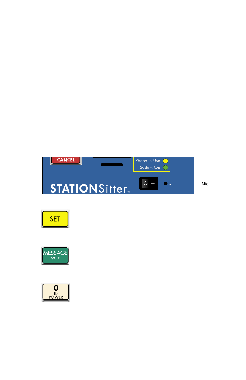
To program the ID Message:
1. Locate the condenser mic.
2. Press the SET key.
3. Press the MESSAGE key.
Press ID key (number 0 key).
5. When the unit beeps, begin speaking your message into the
microphone. The microphone is located next to the power
switch on the front panel. The unit will say “OK,” when the
recording time has elapsed; then it will play back your recorded
message.
4.
53
Page 54
Sensaphone STATIONSitter Manual
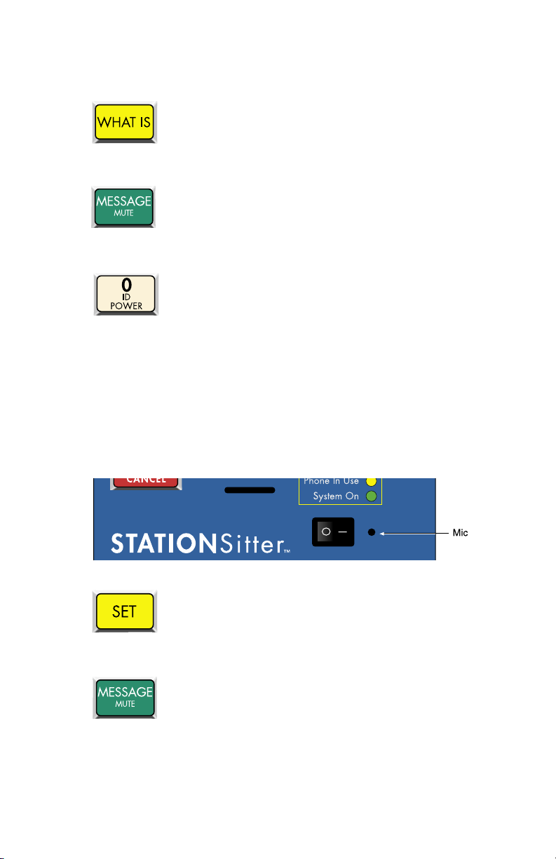
To play back the ID Message:
1. Press the WHAT IS key.
2. Press the MESSAGE key.
3. Press the ID key (number 0 key).
4. The STATIONSitter will play back your recorded message.
The Zone Messages are used to identify the device or condition
being monitored such as temperature, humidity, equipment alarms,
security alarms, etc.
To program the Voice Message for Zone 1:
1. Locate the condenser mic.
2. Press the SET key.
3. Press the MESSAGE key.
4. Press number 1 key (substitute other Zone numbers to record
their respective messages).
54
Page 55
Chapter 5: Communication Programming
5. When the unit beeps begin speaking your message into the
microphone. The microphone is located next to the power
switch on the front panel. The unit will say “OK,” when the
recording time has elapsed; then it will play back your recorded
message.
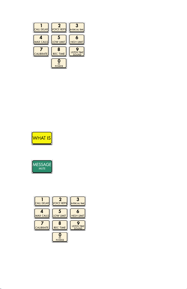
To play back the message for Zone 1:
1. Press the WHAT IS key.
2. Press the MESSAGE key.
3. Press the number 1 key (substitute other Zone numbers to hear
their respective messages).
The STATIONSitter will play back your recorded message.
55
Page 56
Sensaphone STATIONSitter Manual
ID NUMBER
The ID Number is the identification number of the STATIONSitter.
This number is typically the telephone number where the unit is
installed, or it may be designated using any number that best suits
your application. The purpose of the ID Number is to immediately
provide the source of any alarm, especially when using multiple
STATIONSitter units in a complex monitoring system. The
ID number is announced during voice alarm messages and displayed
on pagers. The ID Number can be up to 16 digits long.
When the STATIONSitter is called from a remote location, it always
begins its message with the identification number: “Hello, this is
(ID Number).”
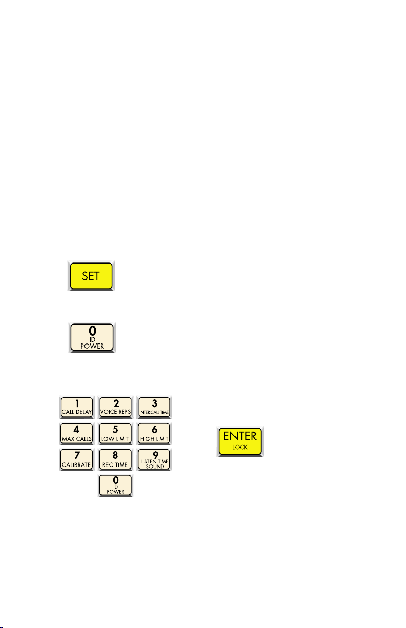
To program the ID Number:
1. Press the SET key.
2. Press the ID key (number 0 key).
3. The unit will say “Enter number.” Using the number keys, enter
the unit’s phone number, then press ENTER.
If the number was accepted, the STATIONSitter will say “OK.”
56
Page 57

Chapter 5: Communication Programming
To play back the ID Number:
1. Press the WHAT IS key.
2. Press the ID key (number 0 key).
3. The STATIONSitter will recite the ID Number.
57
Page 58
Sensaphone STATIONSitter Manual
ALARM DIAL-OUT TELEPHONE NUMBERS
The Sensaphone STATIONSitter will dial up to eight 48-digit phone
numbers to report alarm conditions. These are the numbers that will
be called during an alarm dial-out. The unit can deliver an alarm
message via voice telephone call, numeric page, or alphanumeric
page. Most wireless phones can also receive the alarm message
as text when programmed using the alphanumeric page format.
The telephone numbers are dialed sequentially 1 through 8.
Therefore, program the first number you want called as Phone #1,
the second one as Phone #2, and so on. A pause, pound or asterisk
can be added to the phone number to access different phone and
beeper systems (see Special Dialing Options). Once the alarm is
acknowledged, all dial-out stops.
Voice Dialout
When STATIONSitter calls in Voice mode it will announce the
ID Message and the alarm message. Afterward it will ask for the
acknowledgment code. If a correct code is entered, the unit will stop
dialout. If the wrong code is entered it will hang up and continue
dialing the next number.
To program a VOICE dial-out telephone number:
1. Press the SET key.
2. Press the PHONE NUMBER key.
3. Select which Phone number to program. Press any unassigned
number key (keys 1-8) to represent the new telephone number
entry. STATIONSitter will respond: “Enter number.”
58
Page 59
Chapter 5: Communication Programming
4. Enter the phone number using the number keys, and then press
ENTER.
STATIONSitter will say “OK.”
To play back a programmed dial-out telephone number:
1. Press the WHAT IS key
2. Press the PHONE NUMBER key.
3. Select an assigned Phone number (keys 1-8)
59
Page 60

Sensaphone STATIONSitter Manual
The STATIONSitter will recite the type of call (voice, pager,
alphanumeric pager) and the number programmed. If there is no
number programmed, STATIONSitter will say “No number.”
Numeric Pager Dialout
When programming the STATIONSitter to dial a Numeric pager
there are two methods that can be used:
Manual mode.
The only difference is that in Automatic mode the STATIONSitter
will automatically try to sense when the call has been answered
and then send the ID Number and alarms. In some instances, the
automatic answer detection and timing from the STATIONSitter is
incompatible with the paging service, and the Manual mode must be
used.
Note: If your phone system requires you to dial a
‘9’ followed by a pause to get an outside line, you
must use Manual mode and insert the pauses at the
end of the number.
When the STATIONSitter calls your Numeric Pager it will leave
the programmed ID Number along with the Zone number that is in
alarm. To acknowledge the alarm you will have to call the unit back
and enter an acknowledgment code, otherwise the unit will continue
dialing the remaining numbers.
Automatic mode and
To program a NUMERIC PAGER using AUTOMATIC
Mode:
1. Press the SET key
2. Press the PHONE NUMBER key
3. Select which Phone number to program. Press any unassigned
number key (keys 1-8) to represent the new telephone number
entry. STATIONSitter will respond: “Enter number.”
6060
Page 61
Chapter 5: Communication Programming
4. Press CODE 3 (This tells STATIONSitter this is a Numeric
pager call).
5. Enter the pager telephone number using the number keys. Then
press ENTER.
The STATIONSitter will say “OK.”
To program a NUMERIC PAGER using the MANUAL Mode:
1. Press the SET key
2. Press the PHONE NUMBER key
3. Select which Phone number to program. Press any unassigned
number key (keys 1-8) to represent the new telephone number
entry. STATIONSitter will respond: “Enter number.”
61
Page 62
Sensaphone STATIONSitter Manual
4. Press CODE 3 (This tells STATIONSitter this is a Numeric pager
call).
5. Enter the pager telephone number using the number keys.
6. Press CODE 1 twice.
Note: Depending on your pager service, you may
need to insert a longer or shorter delay (additional
pauses). Two pauses is the recommended starting
point. Use the Dial-out Test Mode to help determine
the proper number of pauses for your pager service.
When it is programmed properly, you will hear the
STATIONSitter dial your pager service, then wait
(based on the number of pauses) until the call has
been answered, and then send another series of
Touch-Tones and hang up.
62
Page 63
Chapter 5: Communication Programming
7. Press the ENTER key.
To play back a NUMERIC PAGER number:
1. Press WHAT IS
Press the PHONE NUMBER key
3. Select the programmed Phone Number from the number keys
(keys 1-8). STATIONSitter will recite the type of call, “pager,”
followed by the pager number assigned to that key.
2.
Alphanumeric Pager Dialout
When the STATIONSitter sends a text message to your
alphanumeric pager (or wireless phone) it must connect with your
service provider’s paging terminal. This is a telephone number that
is answered by a modem. Your service provider’s paging terminal
must support TAP protocol. This is the standard protocol used by
most major service providers. You will need to know this telephone
number and your pager ID Number to program this type of call
into the STATIONSitter. If you don't know the paging terminal
number or your pager ID Number, contact your service provider
(or visit their web page).
63
Page 64
Sensaphone STATIONSitter Manual
When sending text messages to your wireless telephone, the pager
ID is typically the telephone number of your phone. Many wireless
phone providers have toll-free national numbers for their paging
terminals. The list below is provided for your convenience.
TAP Protocol Paging Terminal Phone Numbers
AT&T Wireless: 800-841-8837
Cingular Wireless: 800-469-5351
MCI: 800-759-6366
Mobil Comm: 800-946-4644
NEXTEL National: 800-201-2501
Sprint: 888-656-1727
Verizon Wireless: 866-823-0501
To program an ALPHANUMERIC PAGER dial-out
telephone number:
1. Press the SET key
2. Press the PHONE NUMBER key
3. Press any unassigned number key (keys 1-8) to represent the
new telephone number entry. STATIONSitter will respond:
“Enter number.”
64
Page 65
Chapter 5: Communication Programming
4. Press CODE 4 (tells STATIONSitter this is an Alpha Numeric
pager call). STATIONSitter will say “Alpha Pager.”
5. Enter the telephone number of your paging terminal using the
number keys.
6. Press CODE 5 (this tells the STATIONSitter that the next digits
will be the pager ID number).
STATIONSitter will say “Alpha ID.”
7. Using the number keys, enter the pager ID Number and then
press ENTER.
The STATIONSitter will say “OK.”
To play back an ALPHANUMERIC PAGER number:
1. Press WHAT IS
65
Page 66
Sensaphone STATIONSitter Manual
2. Press the PHONE NUMBER key
3. Select the programmed Phone Number from the number keys
(keys 1-8). STATIONSitter will recite the the type of call,
“Alpha Pager,” followed by the paging terminal number and the
Alpha ID Number.
To delete a dial-out telephone number:
1. Press the SET key.
Press the PHONE NUMBER key.
3. Select the Phone number (1-8) to erase.
The STATIONSitter will say “Enter number.”
4. Press the ENTER key. STATIONSitter will say “OK.”
66
2.
Page 67
Chapter 5: Communication Programming
SPECIAL DIALING OPTIONS
The STATIONSitter has provisions for special dialing requirements.
These including dialing a * or #, inserting a two-second pause, or
forcing the system to wait for the called party to answer. These
options are typically used when: (a) the unit is connected to a PBX
and must dial a ‘9’ or extension to reach an outside line; (b) when
dialing a business and stepping through menus to reach a specific
extension; or (c) when a pager service is answered by a voice menu.
The special dialing commands can be inserted as part of the dialout
telephone number. Valid commands are listed below:
A # tone can be dialed by inserting the Table Range/# key in
the telephone number.
The * tone can be dialed by inserting the Rings/Tad/* key in
the telphone number.
A two-second pause can be inserted in the dialout telephone
number by pressing CODE 1.
The STATIONSitter can be instructed to wait for the call to
be answered before dialing additional digits. This is useful
if you need to call a company’s main number and then dial
additional digits to go to a specific extension (Example:
888-555-1200—wait for answer—227). Press CODE 2 to
make the unit wait for an answer.
67
Page 68

Sensaphone STATIONSitter Manual
Blind Dialing
The STATIONSitter normally checks for a dial tone before dialing.
However, if your telephone system does not produce a dial tone,
you can make the STATIONSitter dial blindly (i.e., without dial
tone). To do this, make the f irst digit of each telephone number
a pause (CODE 1). When the STATIONSitter sees this as the
first digit, it will not check for a dial tone, but dial the number
regardless.
Special Dialing Codes for the STATIONSitter are:
Code 1: two second pause
Code 2: Wait for answer
Code 3: Numeric pager type
Code 4: Alphanumeric pager type
Code 5: Alphanumeric pager ID Number
Code 6: Change to Touch-Tone dialing
68
Page 69
Chapter 5: Communication Programming
DIAL-OUT TEST MODE
The STATIONSitter allows you to test your telephone programming
by simulating an alarm dialout to any programmed telephone
number. This can be a valuable tool for insuring that your
programming is correct and also for troubleshooting dialing
problems. In this mode all signals on the telephone line are audible
through the local speaker.
To test a dialout phone number:
1. Press the SET key.
2. Press the TEST key.
The STATIONSitter will say “Enter Number.”
3. Press a number key (1-8) corresponding to the phone number
entry you wish to test, and press ENTER.
The STATIONSitter will dial the number and send a test message.
69
Page 70
Sensaphone STATIONSitter Manual
ALARM ACKNOWLEDGMENT CODES
When the STATIONSitter detects an alarm, it starts dialing each
telephone number until it receives acknowledgment. An alarm
can be acknowledged either by pressing the ALARM CANCEL
button on the keypad and entering an Acknowledgment Code, or
by entering the Acknowledgment Code over the telephone using
touch tones. An Acknowledgment Code is made up of five digits:
the user’s entry number (1-8) plus a four-digit code. Up to eight
different Acknowledgment Codes may be programmed into the
unit to identify individual users in the Alarm History Log. When
the unit makes a telephone call in Voice mode it will prompt the
user to enter an Acknowledgment Code. If this is entered correctly,
the STATIONSitter will say “Alarm Acknowledged.” When an
alarm message is sent to a pager, the person who receives the page
will have to call the unit back to acknowledge the alarm. When
acknowledging an alarm, the user must first press their entry
number (1-8), and then their programmed 4-digit Acknowledgment
Code. Acknowledgment Code 1 defaults to 1234, so to acknowledge
an alarm the user would have to enter 11234. All other Codes (2-8)
are not programmed by default.
To Program an Acknowledgment Code:
1. Press SET
2. Press CODE
3. Press a telephone number entry (1-8)
70
Page 71
STATIONSitter will say “Enter code.”
4. Enter a 4-digit acknowledgment code.
The STATIONSitter will say “OK.”
To play back an Acknowledgment Code:
1. Press WHAT IS
2. Press CODE
3. Press a telephone number entry 1-8
Chapter 5: Communication Programming
The STATIONSitter will recite the Acknowledgment Code for the
selected telephone number entry.
71
Page 72
Sensaphone STATIONSitter Manual
ALARM HISTORY
The STATIONSitter will retain historical information on the last
10 alarms. The information retained includes: Zone number,
the time/date that the alarm occurred, and the User number that
acknowledged the alarm.
To hear the Alarm History:
1. Press the WHAT IS key.
2. Press the HISTORY key.
The unit will recite the history for the last 10 alarms. A sample
report is shown below:
“Zone 1 (custom message) alarm high at 3:31
PM 4/8/2003
acknowledged by number 4”
“Zone 8 (custom message) alarm low at 2:35
AM 3/27/2003
acknowledged by number 1”
Deleting the Alarm History
The Alarm History can be deleted by pressing SET, then HISTORY.
72
Page 73

Chapter 5: Communication Programming
TONE OR PULSE DIALING
The STATIONSitter can dial out in pulse or touch-tones. All
numbers will be called using the chosen dialing method. The default
is TONE.
To program as either Tone or Pulse:
1. Press the SENSOR ON/OFF key.
2. Press the PHONE NUMBER(T/P) key.
The unit will say “On” to indicate that Tone dialing is enabled,
it will say “Off ” when tone dialing is disabled (i.e., when pulse
dialing is enabled).
73
Page 74

Sensaphone STATIONSitter Manual
RINGS UNTIL ANSWER
The Rings Until Answer is the number of rings that must occur
before STATIONSitter answers the phone. This value can be from 1
to 15. The default value is 4.
To program Rings Until Answer:
1. Press the SET key
2. Press the RINGS key.
STATIONSitter will say “Enter number.”
3. Using the number keys, enter a value and press ENTER.
The STATIONSitter will say “OK.”
To play back the Rings Until Answer:
1. Press the WHAT IS key
2. Press the RINGS key.
The STATIONSitter will recite the programmed value.
74
Page 75
Chapter 5: Communication Programming
CALL DELAY TIME
The call delay time is the length of time the STATIONSitter will
announce an alarm before it starts the dial-out sequence. This
only applies to the first call. To set delay time between calls, see
INTERCALL TIME. The default call delay time is 30 seconds.
It can be programmed from 0 to 60 minutes. The purpose of
Call Delay is to allow time for personnel at the STATIONSitter’s
installation site to respond to and cancel an alarm before dial-out
begins. During this time, the unit will audibly repeat its “alarm”
message and the front panel alarm LED will blink.
To program call delay time:
1. Press the SET key.
Press the CALL DELAY key.
2.
STATIONSitter will say “Enter minutes.”
3. Enter the number of minutes using the number keys. Then press
ENTER.
STATIONSitter will say “Enter Seconds.”
4. Using the number keys, enter the number of seconds, and then
press ENTER.
75
Page 76
Sensaphone STATIONSitter Manual
The STATIONSitter will say “OK.”
To play back the call delay time:
1. Press the WHAT IS key
2. Press the CALL DELAY key
The STATIONSitter will recite the programmed time.
76
Page 77
Chapter 5: Communication Programming
INTERCALL TIME
The Intercall Time is the programmable period of time the
STATIONSitter waits between making alarm phone calls. Intercall
Time is activated only after alarm dial-out to the first telephone
number fails to be acknowledged. This period can be programmed
from 10 seconds to 60 minutes. The default Intercall Time is 30
seconds.
TIP: When the STATIONSitter is programmed to
make calls to pagers, make sure the intercall delay
time is long enough to give the person carrying the
pager some time to get to a phone to call the unit
back.
If an incoming telephone call is received by STATIONSitter during
the Intercall Time (in between dialing of subsequent telephone
numbers to report an alarm), it will answer the incoming call and
immediately report any existing alarms. The manner in which the
incoming call is answered depends upon whether or not TAD is
enabled or disabled:
If TAD is disabled (default), Rings Until Answer will be the
programmed number of rings.
If TAD (Telephone Answering Device) is enabled, Rings Until
Answer will be
1.
To program intercall time:
1. Press the SET key.
2. Press the INTERCALL TIME key.
STATIONSitter will say “Enter minutes.”
77
Page 78
Sensaphone STATIONSitter Manual
3. Using the number keys, enter the number of minutes, and then
press ENTER.
STATIONSitter will say “Enter seconds.”
4. Using the number keys, enter the number of seconds, and
press ENTER.
The STATIONSitter will say “OK.”
To play back the Intercall Time:
1. Press the WHAT IS key
2. Press the INTERCALL TIME key
The STATIONSitter will recite the programmed time.
78
Page 79

Chapter 5: Communication Programming
CALL PROGRESS
The STATIONSitter monitors call progress when it dials out for an
alarm. If STATIONSitter encounters a busy signal or receives no
answer after eight rings, the unit hangs up, waits the programmed
intercall time and then dials the next phone number. When dialing
some beeper/pager services, the line may be answered before
receiving a ringback. This may interfere with the call progress
detection and result in a failed call to certain phone systems or
beeper/pager services. If this occurs, disable call progress detection.
To disable call progress detection:
1. Press the SENSOR ON/OFF key.
2. Press the STATUS/CONFIG key.
STATIONSitter will respond “Off ” to indicate that call progress has
been turned off.
3. Repeat key sequence to change.
79
Page 80
Sensaphone STATIONSitter Manual
VOICE REPETITIONS
The voice repetitions is the number of times the STATIONSitter
will recite the alarm message per phone call when it dials out. This
can be programmed from 1 to 10 repetitions. The default value is 3
repetitions.
To program the voice repetitions:
1. Press the SET key
2. Press the VOICE REPS key.
STATIONSitter will say, “Enter number.”
3. Using the number keys, enter a value and then press ENTER.
The STATIONSitter will say “OK.”
To play back the number of voice repetitions:
1. Press the WHAT IS key.
2. Press the VOICE REPS key.
The STATIONSitter will repeat the number programmed.
80
Page 81
Chapter 5: Communication Programming
MAX CALLS
The STATIONSitter has the ability to acknowledge itself by using
the Max Calls function. The unit keeps a count of the number of
phone calls it makes for a particular alarm. Once the number of
calls made reaches Max Calls, the STATIONSitter will acknowledge
the alarm and stop the dialout process. The unit indicates it
has reached max calls by saying “alarm acknowledged by (ID
Number).” The max calls can be programmed from 0 to to 255. The
default is 100.
NOTE: If only one Phone Number is programmed,
STATIONSitter will dial a maximum of 15 times, regardless of
the programmed value of max calls, as required by FCC rules.
To program Max Calls:
1. Press the SET key.
2. Press the MAX CALLS key.
STATIONSitter will say “Enter number.”
3. Using the number keys, enter a value, then press ENTER.
The STATIONSitter will say “OK.”
81
Page 82

Sensaphone STATIONSitter Manual
To play back Max Calls:
1. Press the WHAT IS key.
2. Press the MAX CALLS key
The STATIONSitter will recite the value of max calls.
82
Page 83
Chapter 5: Communication Programming
TELEPHONE ANSWERING DEVICE (TAD) COMPATIBILITY
The STATIONSitter can be used on the same telephone line as
a telephone answering device, such as an answering machine,
fax machine, or modem. This feature allows you to call in to
STATIONSitter and bypass the answering device.
To use TAD:
1. Program STATIONSitter’s Rings Until Answer to a greater
number than the rings until answer for your answering device.
For example, STATIONSitter RINGS = 5, device rings = 3.
2. Press the SENSOR ON/OFF key.
3. Press the TAD key.
STATIONSitter will say “On.” (If STATIONSitter says “Off ” repeat
steps 2 and 3.)
4. Once TAD is on, allow the phone to ring once when you call
the unit and then hang up. STATIONSitter recognizes that a call
was made and activates a 30 second internal timer. This allows
you 30 seconds to call the STATIONSitter back.
5. Call back within 30 seconds. STATIONSitter will override the
answering device on this incoming call and answer the phone
on the first ring. STATIONSitter resets the TAD timer after one
incoming call is received. If you want to call the unit again, you
must repeat steps 4 and 5.
83
Page 84
Sensaphone STATIONSitter Manual
LISTEN-IN TIME
The Listen-In Time is the amount of time you can listen to
sounds at the unit’s location during a status call-in. An external
microphone (optional) is required to listen in to on-site sounds. The
programmable range is 0 to 255 seconds. The default setting is 0
seconds (disabled).
To program the Listen-In Time:
1. Press the SET key.
2. Press the LISTEN TIME key.
STATIONSitter will say “Enter seconds.”
3. Using the number keys, enter the seconds, then press ENTER.
The STATIONSitter will say “OK.”
To play back the Listen-in Time:
1. Press the WHAT IS key.
2. Press the LISTEN TIME key
The STATIONSitter will recite the time programmed.
84
Page 85
Chapter 5: Communication Programming
LOCKING THE KEYPAD
The keypad can be locked to prevent unauthorized access to the
STATIONSitter’s programming. This will only prevent programming
from being changed. You may, however, play back programming
parameters and listen to a status report without unlocking the keypad.
To edit programming parameters or record messages, you must
unlock the keyboard by entering the four-digit lock/unlock code.
For call-in access, you may freely listen to a status report but the
lock/unlock code must be entered via touch-tone phone to obtain
programming access if the keypad is in the “locked” mode. If you
enter the correct code, you will gain access to STATIONSitter
to use the phone commands. If you enter the incorrect code,
STATIONSitter will hang up. You cannot program or change the
lock code remotely.
For an explanation of how to use the lock code during a call-in, see
Chapter Eight.
To Lock the keypad:
1. Press the SET key.
2. Press the LOCK key.
STATIONSitter will say “Enter security code.”
3. Using the number keys, enter 4 digits, and press ENTER.
The STATIONSitter will say “OK.”
85
Page 86
Sensaphone STATIONSitter Manual
To Unlock the keypad:
1. Press the WHAT IS key.
2. Press the LOCK key.
STATIONSitter will say “Enter security code.”
3. Using the number keys, enter your 4-digit code and press
ENTER. (If you enter the incorrect code, STATIONSitter will
say “error 2.”)
If the correct code was entered, the STATIONSitter will say “OK.”
NOTE: You may not interrogate the security code. The WHAT
IS key is used to unlock the keypad when the correct code is
entered.
86
Page 87

Chapter 5: Communication Programming
SPEAKER MUTE
When the STATIONSitter dials out with an alarm, it recites the
alarm message over the phone and at the monitor site. The Speaker
Mute command allows you to silence the STATIONSitter at the
monitor site.
To Mute the speaker:
1. Press the SENSOR ON/OFF key.
2. Press the MUTE key
STATIONSitter will say “On” to indicate that the speaker mute is
on. It will say “Off” to indicate when the speaker mute is off.
3. Repeat key sequence to change.
87
Page 88
Sensaphone STATIONSitter Manual
CALLBACK ACKNOWLEDGMENT
This is an optional feature that can be enabled using the keypad
(default=disabled). It allows an alarm to be acknowledged simply
by calling the unit and letting the line ring 10 times. When this
feature is enabled it will temporarily make the Rings Until Answer
set to 10 when an unacknowledged alarm exists. If you receive a
call via Voice or Pager and are unable to send touch-tones, then you
can call the unit back, let the line ring 10 times, and the unit will
answer and say “Alarm Acknowledged.”
Note: If TAD is also enabled, then the STATIONSitter will
answer on 1 ring and acknowledge the alarm.
To Enable the Callback Acknowledgment Feature:
1. Press SENSOR ON/OFF.
2. Press CODE.
The STATIONSitter will say “On” to indicate that Callback
Acknowledgment is enabled. Repeat the key sequence to disable.
88
Page 89

Chapter 6: Pump Control
CHAPTER 6: PUMP CONTROL
The Sensaphone STATIONSitter can be used in Fill or Drain pump
control applications using either float switches or an analog level
transducer. The unit will automatically perform alternating duplex
pump control to allow for equal run times on each pump.
The pump control inputs and outputs are located on the terminal
strip on the right side of the unit. All pump control inputs are
optically isolated. A 24VDC power supply is provided for powering
an analog level transducer. The 24V supply is electrically isolated
from other circuitry on the board. The relay outputs are protected by
gas tube surge suppressors. The relay outputs should ONLY be used
as an intermediate switch to control contactors or motor starters.
NEVER wire pumps directly to the STATIONSitter relay outputs
(see wiring diagrams).
Note: When using float switches to perform pump
control, only normally open float switches may be
used (e.g. the switch is open when no water is pres
ent).
-
Output Wiring
The output relays on the STATIONSitter are for low-current control
signals (2A 120VAC/2A 24VDC).
DO NOT directly connect the power for the pumps
to these relays—THIS WILL PERMANENTLY
DAMAGE THE STATIONSITTER
Use the outputs for intermediate control to turn on motor contactors/
starters that will switch actual power to the pumps. See Figure 1.
.
89
Page 90
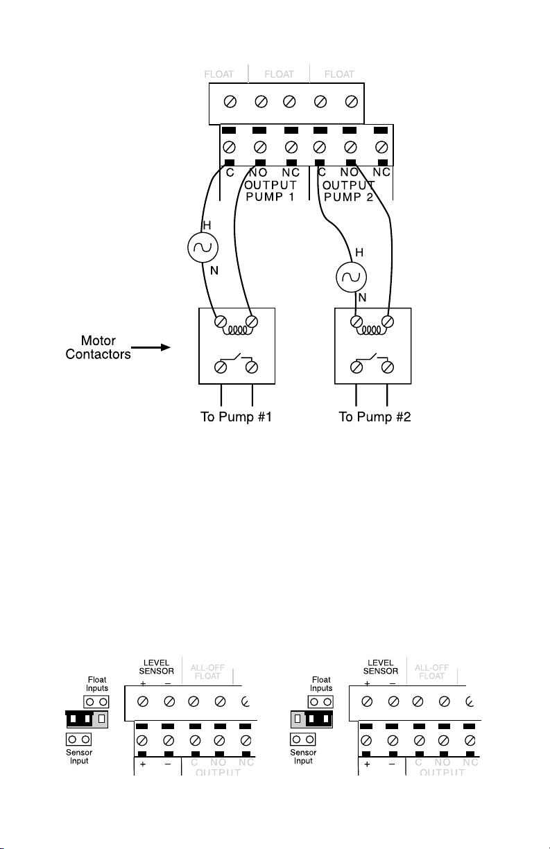
Sensaphone STATIONSitter Manual
Figure 1: Output pump wiring
Note: Hand-operated switches may also be installed
to provide manual override of the system. These
are typically installed for maintenance and safety
purposes.
Level Sensor or Float Switch Selection
There is a jumper next to the pump control terminal strip for
selecting either Analog Level Sensor or Float Switch operation. Set
the jumper accordingly. See Figures 2a and 2b.
Figure 2a: Jumper in analog level sensor position Figure 2b: Jumper in float switch position
90
Page 91
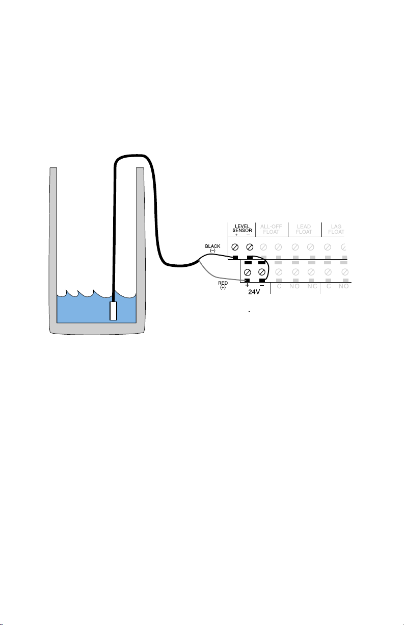
Chapter 6: Pump Control
Analog Level Sensor Wiring
The analog level sensor must be a 4–20mA transducer that is
selected and calibrated based upon the depth of the well. The
calibrated depth values of the transducer must be entered into the
Output Table Range programming of the STATIONSitter, so that the
proper depth is computed (programming is described later in this
section).
Figure 3: Analog level sensor wiring
Float Switch Wiring for Draining the Well
When performing drain pump control using float switches, three
floats are required:
float determines when to turn on the first pump. If the first pump is
unable to bring the level below the All-Off float, then the Lag float
will close, turning on the second pump. When the level drops below
the All-Off float, both pumps are turned off. The STATIONSitter
will automatically alternate between the two pumps to facilitate
uniform run times between the two.
Lead, Lag, and All-Off (See Figure 4). The Lead
91
Page 92
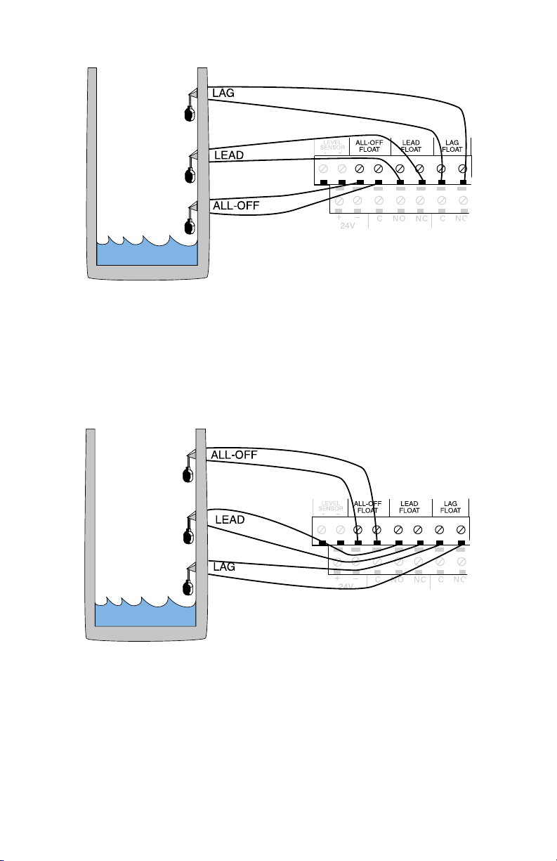
Sensaphone STATIONSitter Manual
Figure 4: Float positions for a drain application
Float Switch Wiring for Filling the Well
In a Fill application, the Lag and All-Off floats would change
position as shown below:
Figure 5: Float positions for a fill application
In this case, the pumps are attempting to keep the well full. When
the well is full, all three floats are closed. If the level drops below
the Lead float, then the first pump will turn on. If the level rises
above the All-Off float then the pump will turn off. If the level
continues to fall below the Lag float, then the 2nd pump will turn
on. Both pumps will remain on until the All-Off float closes.
92
Page 93
Chapter 6: Pump Control
Installation Recommendations
Be sure to install and wire the STATIONSitter and associated
equipment in accordance with all local codes and regulations.
Adhere to Standard Practice/Best Practice policies when installing
and wiring any control system. Be sure to include hand-operated
switches to disconnect power on all pumps/equipment to insure
worker safety when installing and servicing equipment.
Pump Control Programming
The appropriate programming procedure will depend on whether
you are using an analog level sensor or float switches. For
simplicity this has been split up into two sections: Analog Level
Sensor Programming and Float Switch Programming
.
Analog Level Sensor Programming
When using an analog level sensor, you must program the Table
Range of the level sensor, calibrate (if necessary), and then enter the
appropriate Lead, Lag and All-Off levels.
Make sure you have the calibrated range of the Level Sensor
available—this should look something like: 4mA at 0' and 20mA at
15'.
To program the Level Sensor Table Range:
1. Press SET
2. Press TABLE RANGE
3. Press OUTPUT
The STATIONSitter will say “Enter low number.”
93
Page 94
Sensaphone STATIONSitter Manual
4. Enter the sensor low value (typically 0) and press ENTER.
The STATIONSitter will say “OK, Enter high number.”
5. Enter the sensor high value and press ENTER.
The STATIONSitter will say “OK.”
To check the reading from the Level Sensor, press WHAT IS, then
STATUS. The level will be recited near the end of the status report.
To Calibrate the Level Sensor:
1. Press SET
2. Press CALIBRATE
3. Press OUTPUT
The STATIONSitter will say “Enter number.”
4. Enter the offset required to calibrate the reading. For negative
values, precede the entry with the RINGS/TAD/* key. Press
ENTER when finished.
94
Page 95
Chapter 6: Pump Control
To check the programmed calibration for the Level
Sensor:
1. Press WHAT IS
2. Press CALIBRATE
3. Press OUTPUT
The STATIONSitter will recite the calibration value.
Programming the Pump Control Mode
The pump control mode setting is where you select Fill or Drain
mode as well as the Lead, Lag, and All-Off levels.
To program the pump control mode:
1. Press SET
2. Press OUTPUT
The STATIONSitter will say “Enter number.”
3. PRESS 1 (selects pump control). The STATIONSitter will say
“Enter mode.”
95
Page 96
Sensaphone STATIONSitter Manual
For DRAIN mode, PRESS 1.
For FILL mode, PRESS 3.
4. The STATIONSitter will respond by saying “Drain” (or “Fill”
if selected), then “Level,” then “OK.” Next it will say “Enter
1 on.” Enter the Lead level and press ENTER. STATIONSitter
will say “Enter 2 on.” Enter the Lag level and press ENTER.
STATIONSitter will say “Enter 1-2 off.” Enter the All-Off level
and press ENTER.
To check the pump control Mode settings:
1. Press WHAT IS
2. Press OUTPUT
3. Press 1 (selects pump control)
Sample response: “Drain level mode, pump 1 on at 10, pump 2 on
at 15, pump 1-2 off at 5, pump 1 is ON, pump 2 is OFF.”
96
Page 97

Chapter 6: Pump Control
Float Switch Programming
When using float switches to perform pump control with the
STATIONSittter you only need to enable the appropriate pump
control mode (i.e. Drain or Fill). The turn-on and turn-off levels are
determined by the position of the floats in the well.
To program pump control mode using Float Switches:
1. Press SET
2. Press OUTPUT
The STATIONSitter will say “Enter number.”
3. Press 1 (selects pump control)
The STATIONSitter says “Enter mode.”
Press 2 to select DRAIN mode using float switches.
Press 4 to select FILL mode using float switches.
The STATIONSitter will say "OK."
97
Page 98
Sensaphone STATIONSitter Manual
To check the pump control mode settings:
1. Press WHAT IS
2. Press OUTPUT
3. Press 1 (selects pump control)
Sample response: “Drain switch mode”
To disable pump control mode (forces pumps off and
disables pump control logic):
1. Press SET
2. Press OUTPUT
3. Press 1 (selects pump control)
4. Press 0, to disable pump control mode. The STATIONSitter
will say “OK.”
98
Page 99
Chapter 6: Pump Control
Manually Controlling the Pump Outputs
You can manually control the pump outputs from the keypad if
desired. Doing this will disable the pump control mode logic.
To manually turn on or turn off the pump outputs:
1. Press SENSOR ON/OFF
2. Press OUTPUT
The STATIONSitter will say “Enter output number.”
3. Press 1 for Pump 1. Press 2 for pump 2.
The STATIONSitter will say “Enter mode.”
4. Press 1 for ON. Press 0 for Off.
The STATIONSitter will say “Pump 1 On” or “Pump 2 Off ” as
instructed.
99
Page 100

Sensaphone STATIONSitter Manual
Application Example
A wastewater lift station is to be constructed with a 15' well and two
pumps. The design calls for an alternating duplex pump controller.
An analog level sensor is to be used to measure the water level and
control the system. Monitoring of the system is required to detect
pump failure, low/high water level, power failure, etc., such that
any malfunction results in alarm notification via voice and pager
dialout. The Sensaphone STATIONSitter is selected to perform all
of these functions.
The STATIONSitter is installed in a control cabinet along with
battery back-up, pump motor starters, hand operated (HOA)
switches, and indicator lights. The well level sensor is wired to the
unit and its shield is connected to earth ground. Additional float
switches are installed and connected to the STATIONSitter Zone
inputs to monitor for low/high water level alarms. Pump alarm
contacts are also wired to the unit to detect problems with the
pumps.
The STATIONSitter is programmed to operate in Analog Level
Sensor Drain Mode. The Lead value is set to 9', the Lag value is set
to 12', and the All-Off value is set to 3'. A high water float switch
is installed at 13' and a low water float at 1'. In operation this will
allow the well to fill to 9' before turning on the first pump. When
the level drops to 3' the pump will turn off. The next time the level
reaches 9' the second pump will turn on, alternating between the
two each time a pump-down action is required. If the level continues
to rise after the first pump turns on, and it reaches 12', then the
second pump will also turn on. Both pumps will turn off when the
level reaches 3'.
In the event of a power failure, the STATIONSitter will continue
to try and control the system. Since the STATIONSitter has battery
backup, it will continue to measure the water level, monitor the
low/high water float switches and any other alarm points that have
been connected. Assuming the pumps do not have a backup power
source, the water level will continue to rise. If the water level
reaches the high water alarm float the STATIONSitter will notify
the programmed parties so that emergency action can be initiated.
100
 Loading...