

Page 1

SCADA 3000
Annunciator Module
ANNUNCIATOR MODULE
AM-1
Page 2

SCADA 3000 User’s Manual
Every effort has been made to ensure that the information in this document is complete, accurate and up-to-date. Phonetics, Inc. assumes no responsibility for the results of errors beyond its
control. Phonetics, Inc. also cannot guarantee that changes in equipment made by other manufacturers, and referred to in this manual, will not affect the applicability of the information in
this manual.
Copyright 1999 by Phonetics, Inc.
First Edition, version 1.0, July, 1999.
Written and produced by Phonetics, Inc.
Please address comments on this publication to:
Phonetics Inc.
901 Tryens Road
Aston, PA 19014
Sensaphone is a registered trademark of Phonetics, Inc.
For information on updates to this manual, check our website at
www.sensaphone.com
AM-2
Page 3

Annunciator Module
IMPORTANT SAFETY INSTRUCTIONS
Your ANNUNCIATOR MODULE has been carefully designed to give you years of safe,
reliable performance. As with all electrical equipment, however, there are a few basic precautions
you should take to avoid hurting yourself or damaging the unit:
•Read the installation and operating instructions in this manual carefully. Be sure to
save it for future reference.
•Read and follow all warning and instruction labels on the product itself.
•To protect the Annunciator Module from overheating, make sure all openings on the
unit are not blocked. Do not place on or near a heat source, such as a radiator or heat
register.
•Do not use your Annunciator Module near water, or spill liquid of any kind into it.
•Be certain that your power source matches the rating listed in the specification
section of this manual. If you’re not sure of the type of power supply to your facility,
consult your dealer or local power company.
•Do not allow anything to rest on the power cord. Do not locate this product where
the cord will be abused by persons walking on it.
•Do not overload wall outlets and extension cords, as this can result in the risk of fire
or electric shock.
•Never push objects of any kind into this product through ventilation holes as they
may touch dangerous voltage points or short out parts that could result in a risk of
fire or electric shock.
•To reduce the risk of electric shock, do not disassemble this product, but return it to
Phonetics’ Customer Service, or another approved repair facility, when any service or
repair work is required. Opening or removing covers may expose you to dangerous
voltages or other risks. Incorrect reassembly can cause electric shock when the unit is
subsequently used.
•If anything happens that indicates that your Annunciator Module is not working
properly or has been damaged, disconnect it immediately and follow the procedures
in the manual for having it serviced. Return the unit for servicing under the following conditions:
1. Liquid has been spilled into the product or it has been exposed to water.
2. The unit has been dropped, or the enclosure is damaged.
3. The unit doesn’t function normally when you’re following the operating
instructions.
FCC Requirements
Part 15: This equipment has been tested and found to comply with the limits for a Class A
digital device, pursuant to Part 15 of the FCC Rules. These limits are designed to provide
reasonable protection against harmful interference when the equipment is operated in a commercial environment. This equipment generates, uses and can radiate radio frequency energy
and, if not installed and used in accordance with the instructions, may cause harmful interference
to radio communications. Operation of this equipment in a residential area is likely to cause
harmful interference in which case the user will be required to correct the interference at his
own expense.
AM-3
Page 4

SCADA 3000 User’s Manual
Contents
SCADA 3000..................................................................................................... 1
Annunciator Module......................................................................................... 1
Important Safety Instructions ........................................................................... 3
FCC Requirements .............................................................................................................................. 3
Introduction...................................................................................................... 5
Technical Support ............................................................................................................................... 5
Installation........................................................................................................ 6
OPERATING ENVIRONMENT ............................................................................................... 6
MOUNTING THE ANNUNCIATOR MODULE ....................................................................... 6
abeling .............................................................................................................................................. 7
L
Power Supply and Grounding ............................................................................................................. 7
Communications Wiring ..................................................................................................................... 8
Bus Termination .................................................................................................................................. 9
How the Annunciator Module Works.............................................................. 10
Appendix A: Specifications ............................................................................. 11
Appendix B: Returning Module for Service..................................................... 12
Important Information for Canadian Customers ................................................................................. 12
WARRANTY.................................................................................................... 13
AM-4
Page 5

Introduction
The SCADA 3000 Annunciator Module is an optional component for use with the SCADA
3000 system. The module provides 8 programmable LED indicators to display the status of
assigned I/O points. The LEDs are bi-color (red/amber), which means that each LED is always
on, thereby preventing a false reading due to a burned-out LED. Red indicates an active or ON
condition and Amber indicates an inactive or OFF condition. The Annunciator LEDs appear as
two-state (ON/OFF) outputs in the SCADA 3000 software. The Annunciator module is housed
1
in a
/8 DIN enclosure for convenient panel mounting.
Technical Support
If any questions arise upon installation or operation of the Annunciator Module, please contact
Phonetics Customer Service Department at the number shown below and have the following
information:
Annunciator Module
• Date of purchase __________________
• Serial number __________________
Technical support is available from 8:00 AM to 5:00 PM, EST.
You can also contact technical support at any time via e-mail at: [email protected]
Phonetics, Inc.
901 Tryens Road
Aston, PA 19014
Phone: (610)558-2700
FAX: (610)558-0222
www.sensaphone.com
AM-5
Page 6

SCADA 3000 User’s Manual
Installation
This chapter provides information necessary to install the Annunciator Module. Correctly
installing the unit will ensure proper functioning and maximum service life. Please read the
entire chapter before attempting installation.
OPERATING ENVIRONMENT
The Annunciator Module should be mounted and operated in a clean, dry and safe environment.
Do not mount the unit where it will be subject to shock and vibration. Do not mount the unit
where it will be subject to dirt, dust or moisture. Ideally the unit would be mounted in a steel or
a fiberglass NEMA-4 enclosure. Do not mount the unit or the expansion modules close to
motor starters, contactors or relays that switch inductive loads. These devices generate large
electromagnetic fields that can cause the Annunciator Module to malfunction. Where this is
unavoidable, mount the module(s) and main unit in a separate, grounded, steel enclosure. This
will shield them from harmful electrical interference.
The temperature range the Annunciator Module can operate in is 32°F to 158°F (0°C to 70°C).
If you require Annunciator Module to operate in a below freezing environment, you must take
safe and practical measures to keep the module’s temperature above 32°F or it will not operate
reliably.
CAUTION: The Annunciator Module is a sensitive electronic device. Personnel
and work area should be grounded before handling this device. Do not install a
SCADA 3000 system near any strong electrostatic, electromagnetic, magnetic or
radioactive fields. Do not expose it to fumes or corrosive vapors.
MOUNTING THE ANNUNCIATOR MODULE
The Annunciator Module is packaged in a standard 8 DIN enclosure. This style of enclosure is
designed to be flush-mounted in a panel or door. The module includes all the hardware necessary for mounting; however, a small Allen wrench will be required to secure the enclosure to the
panel. To mount the module, cut a hole in the panel according to the dimensions shown in
Figure 1 below.
3.58"
1.73"
AM-6
Figure 1: Module Mounting Dimensions
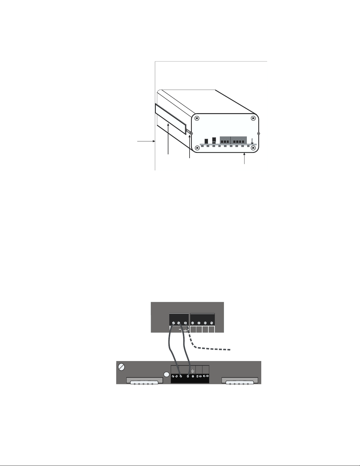
Remove the two Allen screws on the back of the enclosure and slide out the locking side panels.
Insert the module into the hole in the panel and slide it back until the front bezel is flush with
Page 7
Annunciator Module
the panel. Re-install the locking side panels and tighten the Allen screws to secure the enclosure
to the panel. See Figure 2 below.
Panel
locking
side
panel
Allen
screw
Rear of
Module
Figure 2: Rear view of mounted annunciator module
Labeling
The Annunciator Module comes with a blank label on the front on which you can write a description to identify each light—such as the corresponding alarm or output. We include additional blank labels for your convenience.
POWER SUPPLY AND GROUNDING
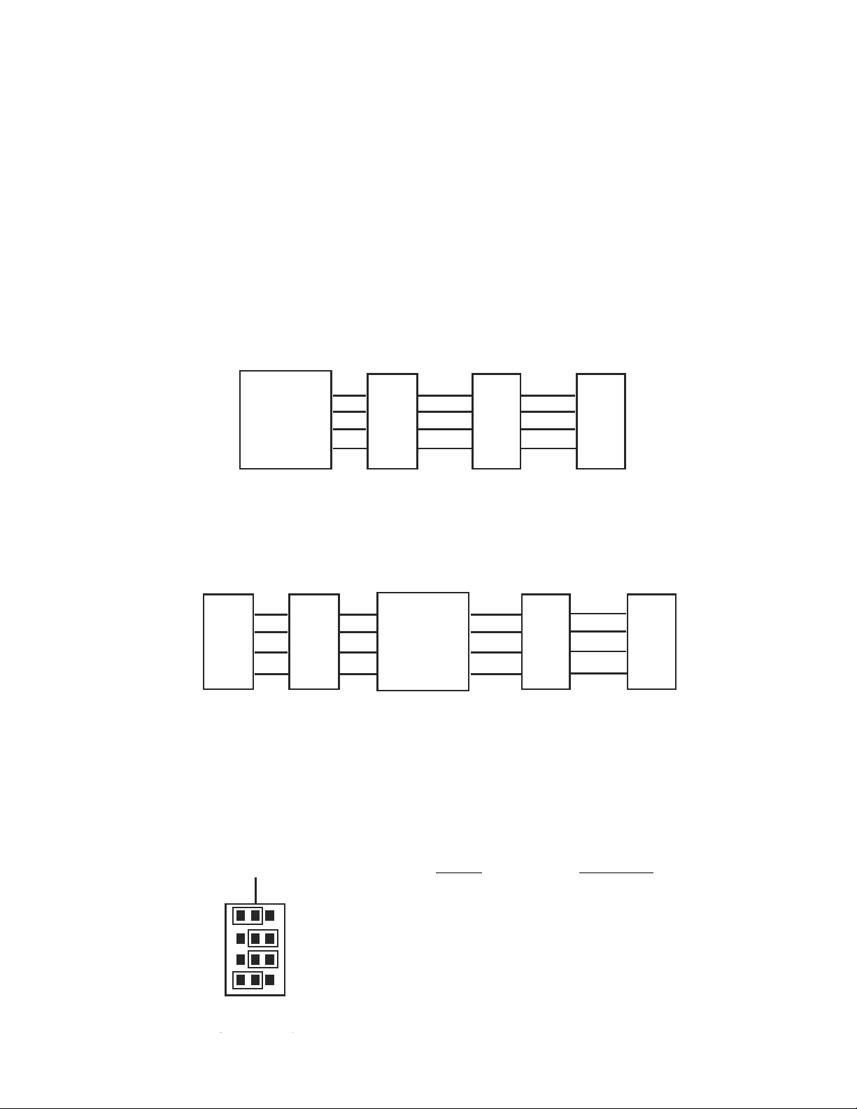
The Annunciator Module operates on 10-15VDC. Typically the module is powered from the
AUX PWR terminals on the SCADA 3000 main unit. This is preferred because the AUX PWR
from the main unit is battery-backed in the event of a power failure, when a battery is connected
to the main unit. Alternately, you may connect the module to any 10-15VDC power source.
The module requires 1.5 Watts of power. See Figure 3.
Annunciator Module
AUX
EG
+
12VIN
ABYZ
4
Connect to Electrical
Earth Ground
15V
AUX
BAT
EG
RS232-DCE
COM 1
SPARE
+IN-
+PWR-
FUSE
SCADA 3000
4A
+ -
24V
RS232-DTE
COM 2
Figure 3: Annunciator Module connected to the SCADA 3000
It is extremely important that the EG pin be connected to a good earth ground. This will
prevent communication errors due to differences in ground potential between modules in
addition to possible damage due to voltage transients and surges.
AM-7
Page 8
SCADA 3000 User’s Manual
COMMUNICATIONS WIRING
The Annunciator Module communicates with the SCADA 3000 using a high-speed serial
communications bus. This 4-wire bus is used to connect up to 15 modules to the main unit to
provide additional inputs and/or outputs. Perform all wiring with power to the main unit and
modules turned off.
Modules may be located a maximum of 2000' away from the main unit and should be connected
in a daisy-chain fashion from one module to the next. Each module connects to the next via a 4wire communications cable connected to the terminals labeled A,B, Z & Y. The cable must be
4-Conductor Twisted Pair (shielded or unshielded) with a nominal impedance of 120Ω (for
example, Belden #8132 or 9842 cable). Use one pair for A & B and the other pair for Z & Y. The
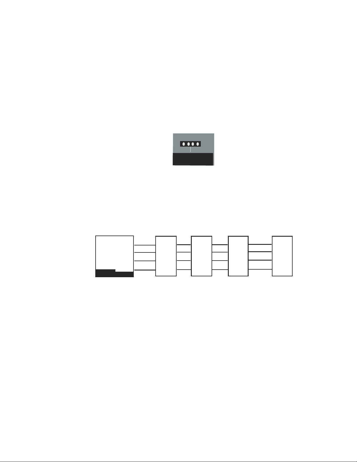
proper wiring from the main unit to the modules, and from module to module, is shown in
Figure 3:
SCADA 3000
A
B
Z
Y
Figure 3: Correct daisy chain setup: Main unit on the end.
Module
Y
Z
B
A
Figure 4: Incorrect daisy chain setup: Main unit in the middle of the chain.
The Main Unit should always be on one end of the chain, never in the middle.
Module Module
Y
Z
B
A
reversedstraight-thru
Module Module Module
Y
Z
B
A
reversed
SCADA 3000
A
B
Z
Y
Y
Z
B
A
straight-thru straight-thru
Y
Z
B
A
reversed
Y
Z
B
A
Module
Y
Z
B
A
straight-thru
AM-8
Each module must be configured with its own unique address using the BUS ADDRESS
jumpers. You may mix & match up to 15 modules to suit your application’s requirements. The
example below shows a Bus Address setting of 9.
Address Jumper Code
A B
1
2
3
4
BUS
ADDRESS
1 A B B B
2 B A B B
3 A A B B
4 B B A B
5 A B A B
6 B A A B
7 A A A B
8 B B B A
9 A B B A
Page 9
Annunciator Module
10 B A B A
11 A A B A
12 B B A A
13 A B A A
14 B A A A
15 A A A A
Figure 5: Setting the Bus Address
Bus Termination
Located on each module is a jumper labeled BUS TERM. This jumper is used to terminate the
4-wire communications bus.
BUS TERM
IN OUT
Figure 6: Bus Termination jumper
Termination is required at the extreme ends of the communications network to minimize signal
reflections that would otherwise cause data communication errors. To activate the Bus Termination, move the jumper to the IN position. Note that this should only be activated if the module
is at the very end of the network. All other modules in between should have the termination set
to the OUT position. As a result, only 1 module should ever have the termination activated.
The diagram below illustrates proper termination of the communications bus.
0
Main
Unit
In
Out
Figure 7: Correct bus termination
Out
Out
In
AM-9
Page 10

SCADA 3000 User’s Manual
How the Annunciator Module Works
The Annunciator module appears as an output module to the SCADA 3000. When the system
is powered up, the main unit will scan the external module network and add the Annunciator to
its list of modules at the address specified by the Bus Address jumpers. An icon for the Annunciator will also appear on the main unit screen.
The Annunciator module provides eight LED indicators which can be used to display the status
of I/O points, system variables, or alarm conditions. The LEDs can be forced on (Red) or off
(Amber) through the Annunciator module programming screen, or they may be controlled
automatically using a C-program or Ladder program. The eight LEDs appear in the programming software as digital outputs numbered from 0-7. To access the Annunciator programming
screen, click on the Annunciator icon from the Main Unit form or select Modules, then Annunciator, from the main menu.
AM-10
Page 11

Appendix A: Specifications
Annunciator Module
:etaRataDkrowteN
:ecnadepmInoitanimreTsuB
:stnemeriuqeRrewoP
:epyt&gnitaResuFrewoP
:erutarepmetgnitarepO
:erutarepmeTegarotS
ytidimuH
:snoisnemiD
:thgieW
:erusolcnE
8 slenapedisgnikcolhtiwgnisuoHmunimulANID
spbK6.351
smhO021
)lacipyt(Am00lCDV5l-0l
)lacipyt(W5.l
)1400041273#nnamkciW(5-RTeziS,V052Am005
)Fseerged851ot23(suisleCseerged07ot0
)Fseerged851ot4-(suisleCseerged07ot02-
gnisnednoc-non%09ot5
"6.5x"58.1x"8.3
.sbl57.0
.noitallatsnilenaprof
AM-11
Page 12

SCADA 3000 User’s Manual
Appendix B: Returning Module for Service
In the event that the Annunciator Module does not function properly, we suggest that you do
the following:
1) Record your observations regarding the Annunciator Module malfunction.
2) Call the Customer Service Department at (610)558-2700 prior to sending the
unit to Phonetics for repair.
If the module must be sent to Phonetics for Servicing, please do the following:
1) Disconnect all wiring and unplug the unit.
Note that the terminal blocks can be unplugged from the unit to maintain
your input wiring.
2) Carefully pack the module to avoid damage in transit. Use the original container
(if available) or a sturdy shipping box.
3) You must include the following information to avoid shipping delays:
a) Your name, address and telephone number.
b) A note explaining the problem.
4) Ship your package to the address below:
SERVICE DEPARTMENT
Phonetics Inc.
901 Tryens Road
Aston, PA 19014
5) Ship prepaid and insured via UPS or US Mail to ensure a traceable shipment with
recourse for damage or replacement.
Important Information for Canadian Customers
In the event that your Sensaphone SCADA 3000 unit does not function properly, Canadian
customers have the option of shipping the unit to one of the following Phonetics-authorized
Canadian Repair facilities:
Microwise Computer Systems G.A.S. Analytical Systems, Ltd.
100 Covington Crescent Head Office
Kitchener, Ontario N2N 2X3 Bay V, 1338 36 Avenue NE
(519) 744-9892 Calgary, Alberta T2E 6T6
(403) 253-6576
Please record your observations regarding the unit’s malfunction and follow the procedures
outlined on the previous page.
AM-12
For Technical Support questions, you may call Phonetics Technical Service Department at (610)
558-2700, or by E-mail at [email protected].
Page 13

Annunciator Module
3 YEAR LIMITED WARRANTY
1. WARRANTOR: Dealer, Distributor, Manufacturer
2. ELEMENTS OF WARRANTY: This Product is warranted to be free from defects in
materials and craftsmanship with only the limitations and exclusions set out below.
3. WARRANTY AND REMEDY: Three-Year Warranty — In the event that the Product
does not conform to this warranty at any time during the time of three years from
original purchase, warrantor will repair the defect and return it to you at no charge
This warranty shall terminate and be of no further effect at the time the Product is (1)
damaged by extraneous cause such as fire, water, lightning, etc. or not maintained as
reasonable and necessary; (2) modified; (3) improperly installed; (4) repaired by someone other than warrantor; (5) used in a manner or purpose for which the Product was
not intended; or (6) sold by original purchaser.
WARRANTORS’ OBLIGATION UNDER THIS WARRANTY IS LIMITED TO REPAIR OR
REPLACEMENT OF THE PRODUCT. THIS WARRANTY DOES NOT COVER PAYMENT
OR PROVIDE FOR THE REIMBURSEMENT OF PAYMENT OF INCIDENTAL OR CONSEQUENTIAL DAMAGES.
It must be clear that the warrantors are not insuring your premises or guaranteeing that
there will not be damage to your person or property if you use this Product. The
warrantors shall not be liable under any circumstances for damage to your person or
property or some other person or that person’s property by reason of the sale of this
product or its failure to operate in the manner in which it is designed. The warrantors’
liability, if any, shall be limited to the original cost of the Product. The warrantors
assume no liability for installation of the Product and/or interruptions of the service due
to strikes, riots, floods, fire, and/or any cause beyond Seller’s control.
4. PROCEDURE FOR OBTAINING PERFORMANCE OF WARRANTY: In the event
that the Product does not conform to this warranty, the Product should be shipped or
delivered freight prepaid to a warrantor with evidence of original purchase.
5. LEGAL REMEDIES: This warranty gives you specific legal rights, and you may also
have other rights which vary from state to state to the extent allowed by law expressly
in lieu of any other express or implied warranty, condition, or guarantee.
Effective date: 1 June 1999
Phonetics, Inc.
901 Tryens Road
Aston, PA 19014
Phone: (610) 558-2700 Fax: (610) 558-0222
AM-13
 Loading...