

Page 1

ISACC MANAGER for
Windows
User’s Manual
Version 2.1.145
Phonetics, Inc.
Page 2

Every effort has been made to ensure that the information in this document is complete,
accurate and up-to-date. Phonetics, Inc. assumes no responsibility for the results of errors
beyond its control. Phonetics, Inc. also cannot guarantee that changes in equipment made by
other manufacturers, and referred to in this manual, will not affect the applicability of the
information in this manual.
Copyright 1998 by Phonetics, Inc.
Second edition, version 2.1.145, November, 1998.
Written and produced by Phonetics, Inc. Please address all comments on this publication to:
Phonetics, Inc.
901 Tryens Road
Aston, PA 19014
Sensaphone is a registered trademark of Phonetics, Inc.
Touch Tone is a registered trademark of AT&T.
Windows is a registered trademark of Microsoft Corporation.
Page 3

ISACC Manager
Table of Contents
Chapter 1 Getting Started.................................................. 1
Installing and Starting MANAGER ...................................................................1
Installing MANAGER........................................................................................1
Installation Procedure:........................................................................................1
Starting MANAGER ..........................................................................................2
MANAGER Menu Bar.......................................................................................3
Tool Bar ..............................................................................................................4
Chapter 2 Configuring MANAGER for your System.... 5
Local Port Setup .................................................................................................5
Modem Setup......................................................................................................5
Adding a New Unit to your Database.................................................................7
Editing Unit Information ....................................................................................8
Deleting a Unit from your Database...................................................................8
Opening a Unit....................................................................................................9
Closing a Unit...................................................................................................10
Copying Programming using Drag and Drop...................................................11
On-line Programming .......................................................................................11
Off-line (Unit Database) Programming............................................................12
Chapter 3 Programming .................................................. 13
SYSTEM TAB..................................................................................................13
INPUTS TAB....................................................................................................16
OUTPUTS TAB................................................................................................18
PHONE TAB ....................................................................................................19
C PROGRAMMING TAB ...............................................................................21
BLOCK FUNCTIONS .....................................................................................23
KEYBOARD SHORTCUTS ............................................................................24
CONTROL KEYS ............................................................................................24
REAL TIME TAB.............................................................................................26
DATA LOGGING TAB ....................................................................................29
TEXT MODE TAB...........................................................................................34
Page 4

Chapter 4 Receive Alarm Mode ...................................... 35
AUTO ANSWERING ......................................................................................35
VIEWING ALARM INFORMATION.............................................................36
Chapter 5 Real Time Screen Builder .............................. 37
Building your Screen ........................................................................................39
Appendix A T roubleshooting ........................................... 41
Page 5

Chapter One: Getting Started
Chapter 1 Getting Started
ISACC MANAGER can be installed in just a few minutes. The instructions below outline
the procedure and system requirements. It is important to note that this manual is specific to
the ISACC MANAGER software program. For information on ISACC and its operation you
should consult the ISACC Owner’s Manual.
Installing and Starting MANAGER
MANAGER minimum requirements:
• 486 or better computer (Pentium recommended)
• 10 MB of free disk space
• 4 MB RAM (16 MB RAM recommended)
• Graphics card compatible with Microsoft Windows
• Microsoft Windows
• VGA or Super VGA monitor
• Mouse
• Modem
® 3.1, 95 or NT
® 3.1, 95 or NT (such as VGA)
Installing MANAGER
MANAGER’s setup program makes installation quick and easy. You will be prompted to
insert the installation disks in the order they are numbered. Make sure that all windows
applications are closed before attempting to run Setup. If you encounter problems during
installation see Troubleshooting, in Appendix A.
The ISACC MANAGER Software for Windows will install to a directory named
ISACCMAN. If necessary, you may change the directory when prompted during installation.
If you have an older version of MANAGER for DOS, do not use the directory name MANAGER since this will result in overwritten files and program conflicts.
Installation Procedure:
For Windows® 95
1)Start Microsoft Windows.
2)Insert disk 1 in drive A.
5
Page 6
ISACC Manager for Windows
3)Select Start>Settings>Control Panel. Double click on Add/Remove Programs.
4)Follow the prompts to install the software.
For Windows
® 3.1
1)Start Microsoft Windows.
2)Insert disk 1 in drive A.
3)Choose File, then Run, to open the Windows Run dialog box.
4)In the Command Line box, type a:\setup.
5)Click OK, and follow the instructions in the dialog boxes displayed on the screen.
Starting MANAGER
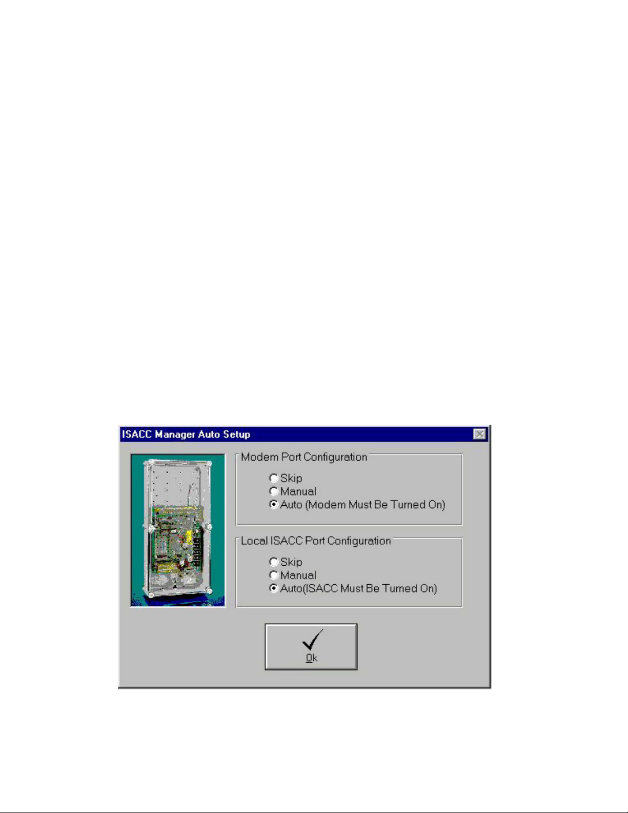
To start MANAGER, position the mouse over the MANAGER icon and double click. When
you run the program for the first time it will ask if would like the software to self-configure
for your system. You may choose to skip this or selectively allow it to configure only your
modem or your local COM port. The Auto procedure is recommended because it simplifies
setting-up your communications. When the software finishes the configuration process you
will see a menu and toolbar with the New Unit form in the MANAGER window. You may
enter the information for a new unit at this time or simply click Cancel to add a new unit
later. The menus and tools at the top of the screen will allow you to open new ISACC units,
communicate with existing ISACC units, observe real-time input values and numerous other
features.
6
Page 7
Chapter One: Getting Started
MANAGER Menu Bar
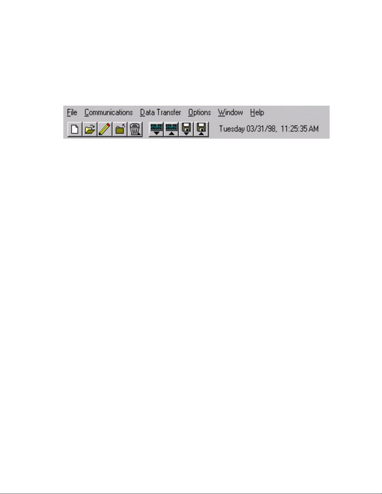
The menu bar at the top of the MANAGER window lists menu commands for selecting a
unit, configuring your communication ports, sending and receiving programming, enabling
automatic features and other functions. You can choose these commands by clicking them
with the mouse. Many frequently used commands are also available as tools on the toolbar.
The following table briefly describes each menu. Shortcut keys that you can use to display
each menu are included in parentheses next to the menu names.
_______________________________________________________________________
Menu name Functions under this menu...
_______________________________________________________________________
File (Alt, F) Adding new units, opening existing units, editing existing
units, closing units and deleting units; printing information;
exiting MANAGER.
_______________________________________________________________________
Communications (Alt, C) Local port setup, modem setup
_______________________________________________________________________
Data Transfer (Alt, D) Sending and receiving unit programming between the
computer and ISACC; Sending and receiving programming
to the computer database; restoring database programming
from MANAGER’s backup copy
_______________________________________________________________________
Options (Alt, O) Enabling/Disabling alarm receiving; Viewing alarm data;
Alarm Reception Settings; Activating/Deactivating polling;
Viewing the polling schedule; Real Time Settings
_______________________________________________________________________
Window (Alt, W) Cascade; Tile; Arrange Icons
_______________________________________________________________________
Help (Alt, H) Accessing MANAGER on-line help; Program Information
_______________________________________________________________________
7
Page 8

ISACC Manager for Windows
Tool Bar
The tool bar appears below the menu bar and is made up of nine buttons. On each button, a
name tag appears when the pointer rests on it. The toolbar allows fast one-click access to the
following ISACC MANAGER functions:
New - Configures a new unit in the database for programming and communication.
Open - Opens a unit for online communication or database programming.
Edit - Permits editing of a unit’s phone number and modem baud rate.
Close - Terminates a communication session whether online or using the database.
Delete - Deletes a unit from the database.
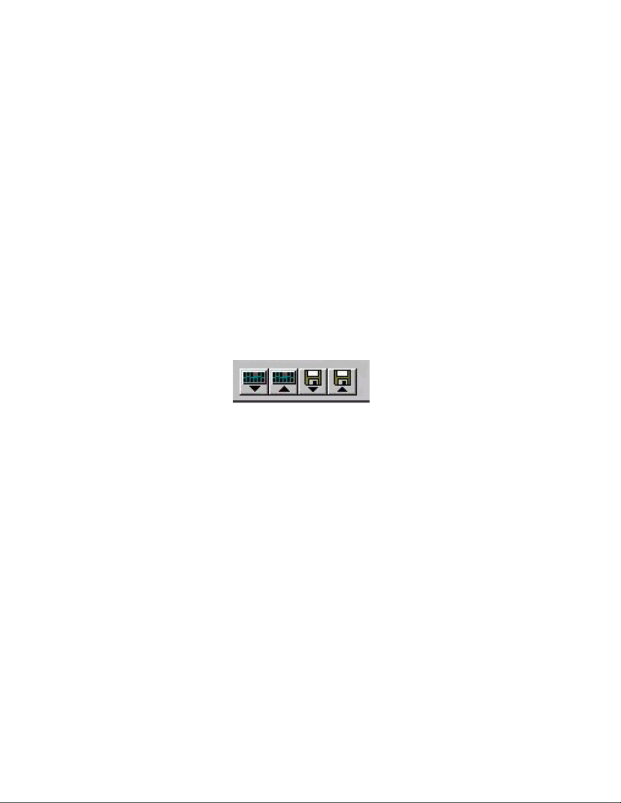
From Unit - Downloads the programming from a unit to the computer screen.
To Unit - Uploads programming from the computer to the unit.
From Database - Retrieves information from the database and puts it on the screen.
To Database - Sends the on-screen programming to the database.
8
Page 9
Chapter Two: Configuring MANAGER
Chapter 2 Configuring MANAGER for your System
ISACC MANAGER will communicate to your ISACC through your computer’s local serial
port or through your modem. These communication paths must be properly configured for a
connection to be established. (If you allowed the software to automatically configure
your system you only need to configure the modem initialization string).
Local Port Setup
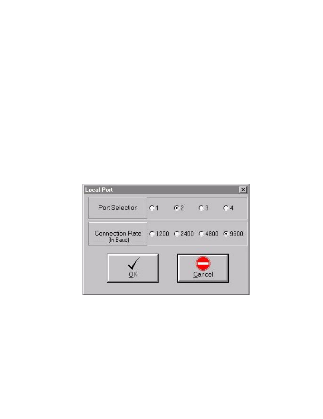
Click on Communications from the menu bar. Click on Local Port Setup. Select the appropriate serial port and baud rate to communicate with ISACC. Select a serial port on your
computer that is unused and can be attached to ISACC’s RS232 port. Note that the maximum (and default) speed at which ISACC can communicate is 9600 baud. When finished
click OK.
Modem Setup
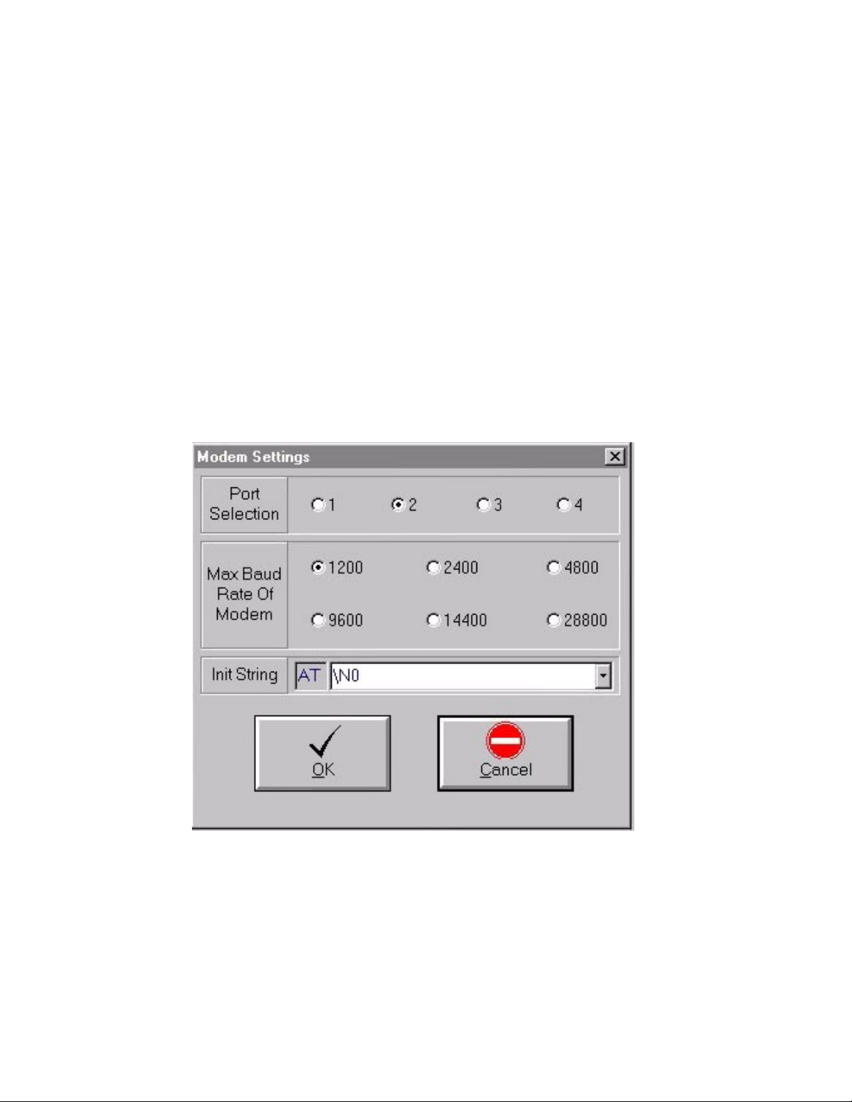
Click on Communications from the menu bar. Click on Modem Setup. Select the serial port
that communicates with your modem and select the maximum baud rate of your modem.
Next, select the appropriate modem initialization string (init string) for your modem. The
initialization string is a command given to your modem to configure it for various communication purposes. Certain modems perform the additional features of data compression and
error correction. The two most common protocols are MNP4-5 and V.42. These special
features conflict with the operation of ISACC’s modem and must be disabled. Check with
your modem owner’s manual to see if you have these features. To disable these features an
9
Page 10
ISACC Manager for Windows
initialization string is sent to the modem. Some common initialization strings are listed in
the drop down box on your screen. Click on the down arrow next to the blank box to see a
list of initialization strings. Select the initialization string that is appropriate for your modem
or type one in that adjusts your modem accordingly. Click on OK when finished. Listed
below are some sample initialization strings for several popular modems.
____________________________________________________________________
Manufacturer & Model Number Initialization String
____________________________________________________________________
Bocamodem M144EW \N0
Intel 9600bps \N0
Practical Peripherals PM144 \N0
U.S. Robotics Sportster14.4 & 28.8kbps &K0&M0
Wisecom 28.8kbps \N0
____________________________________________________________________
Adding a New Unit to your Database
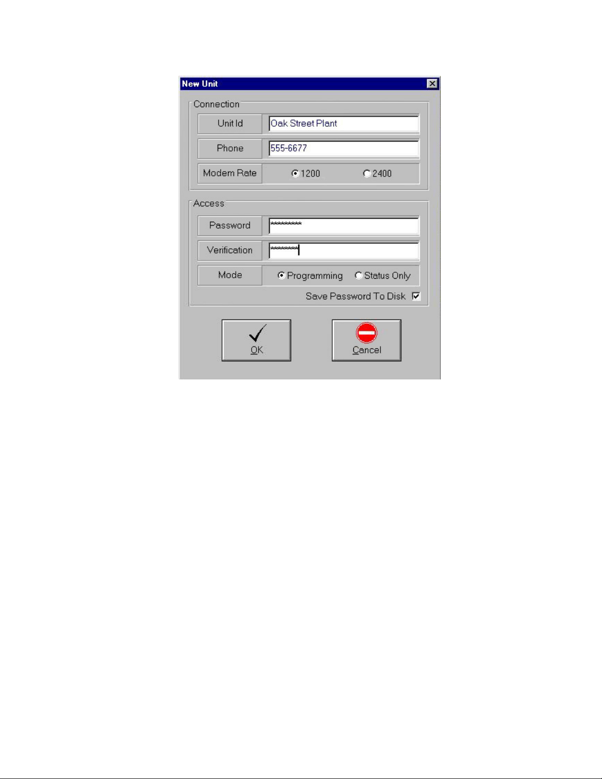
Click on ’New’ from the file menu or click on the “New” toolbar button. The ‘New
Unit’ form will appear.
10
Page 11
Chapter Two: Configuring MANAGER
Enter the Unit ID name, phone number, and modem speed. The Unit ID is the identification
name for the unit and may be up to 31 characters long. This will appear in your unit list and
in other forms. The phone number is the number for your ISACC unit and may be up to 31
characters long. ISACC MANAGER will dial this number when connecting with your
modem. Modem Rate refers to ISACC’s modem speed. This should be set to 1200 for most
applications.
Enter the ISACC unit’s data password under both Password and Verification. The password
may be up to 30 characters long. Next, select either Programming or Status-Only access. If
Programming access is selected, full access to all unit functions is granted when MANAGER
opens the unit. When MANAGER opens a unit with Status-Only access selected, only the
Real Time Status screen and the Data Log screen will be visible. In Status-Only mode, no
programming changes will be allowed.
NOTE: The ISACC Manager database uses the Unit ID as the database key. Therefore it
is imperative that the database and your ISACC unit have identical Unit ID descriptions.
Next, choose whether to save the password to disk. If this box is checked, MANAGER will
automatically enter the programmed password when a unit is opened. If this box is not
checked, MANAGER will prompt you to manually enter the unit’s password when a unit is
opened.
11
Page 12
ISACC Manager for Windows
When connecting to a new unit (a new unit being one with no Unit ID, no unit phone number
and no password), Manager will automatically copy the unit ID, the phone number and
password from the NEW UNIT form into the unit. This ensures that the Unit ID matches the
database.
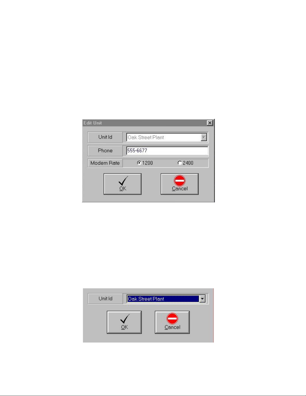
Editing Unit Information
This function permits editing of a unit’s phone number and modem baud rate.
1. Click on Edit from the File menu or click on the “Edit” button on the toolbar.
The ‘Edit Unit’ form will appear.
2. Select a unit from the list, make the desired changes, then click ‘OK’.
Deleting a Unit from your Database
1. Click on ’Delete’ from the file menu or click on the ‘Delete’ toolbar button (trash can).
The ‘Delete Unit’ form will appear.
2. Select a unit from the list.
3. Click ’OK’.
Note: Deleting a unit deletes ALL information pertaining to that unit. This includes unit
programming and any downloaded Data Log, and Alarm Data information.
12
Page 13
Chapter Two: Configuring MANAGER
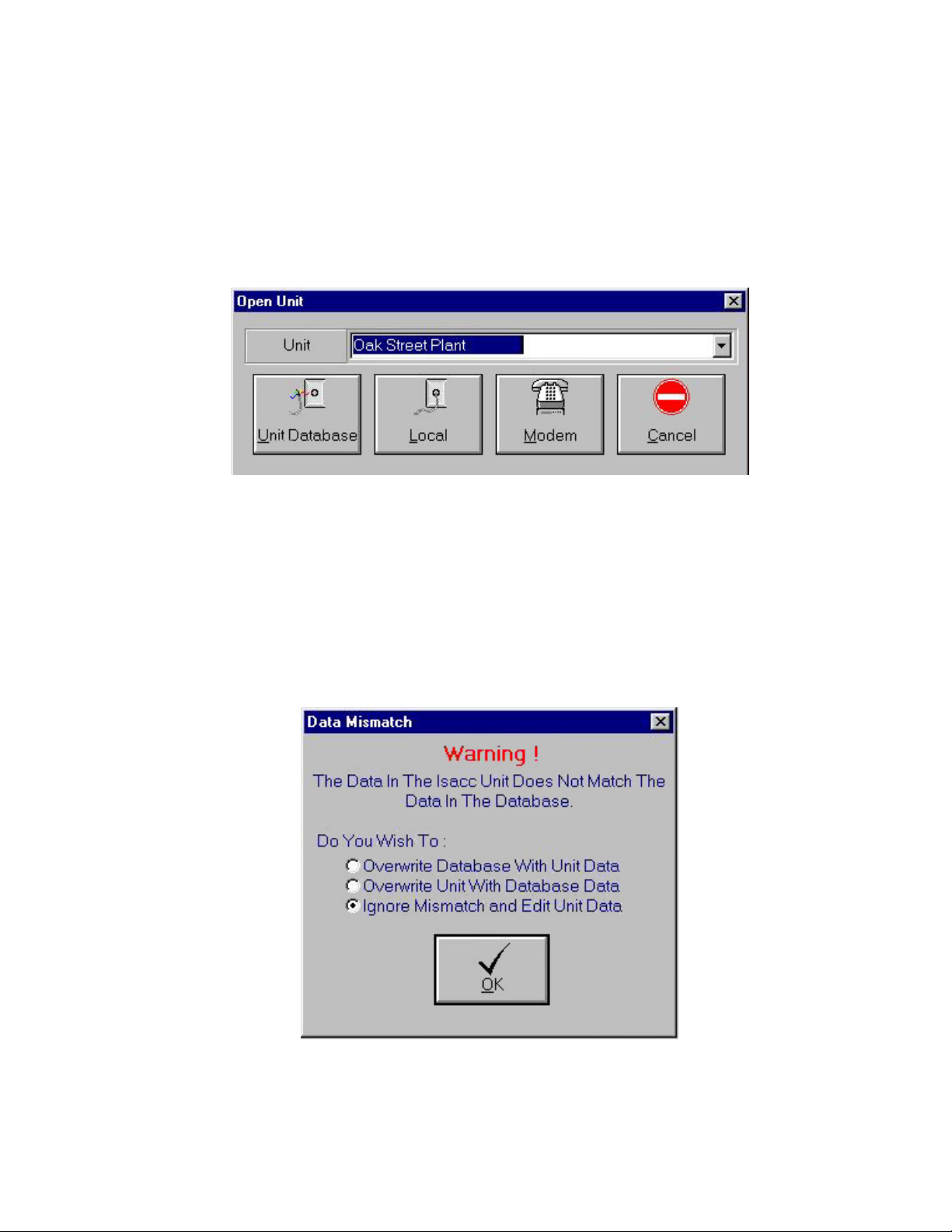
Opening a Unit
1. Click on Open from the File menu or click on the “Open” button on the toolbar.
2. Select a unit from the list.
3. Choose a communication method.
If you Open a Unit using either “Local” or “Modem” communication, you will be connected
directly to an ISACC unit. If you Open a Unit using the ‘Unit Database’ selection, you can
view downloaded Datalogger information, setup a polling schedule or pre-program an
ISACC. The on-line connection (Local or Modem) allows you to make programming
changes and load them into the unit immediately. When you Open a Unit using either “Local” or “Modem” communication, the ISACC’s data is automatically downloaded to the PC
for comparison. If the ISACC’s data does not match the PC’s database data, a “Data Mismatch” warning appears.
13
Page 14

ISACC Manager for Windows
The Data Mismatch form gives you three options:
Overwrite Database With Unit Data - This option will download the programming
from ISACC and copy it into the database. This choice is useful if you are connecting to a previously programmed unit and are connecting to it for the first time using
ISACC Manager for Windows.
Overwrite Unit With Database Data - This option will upload the programming in
your computer Database to ISACC. This choice is useful if you have set all of your
programming in the unit database and wish to copy it into your ISACC unit.
Ignore Mismatch and Edit Unit Data - This option will simply display the
programming in your ISACC unit. No programming will be copied to either your
database or ISACC unit. If you are unsure about what option to select, this is the
safe choice.
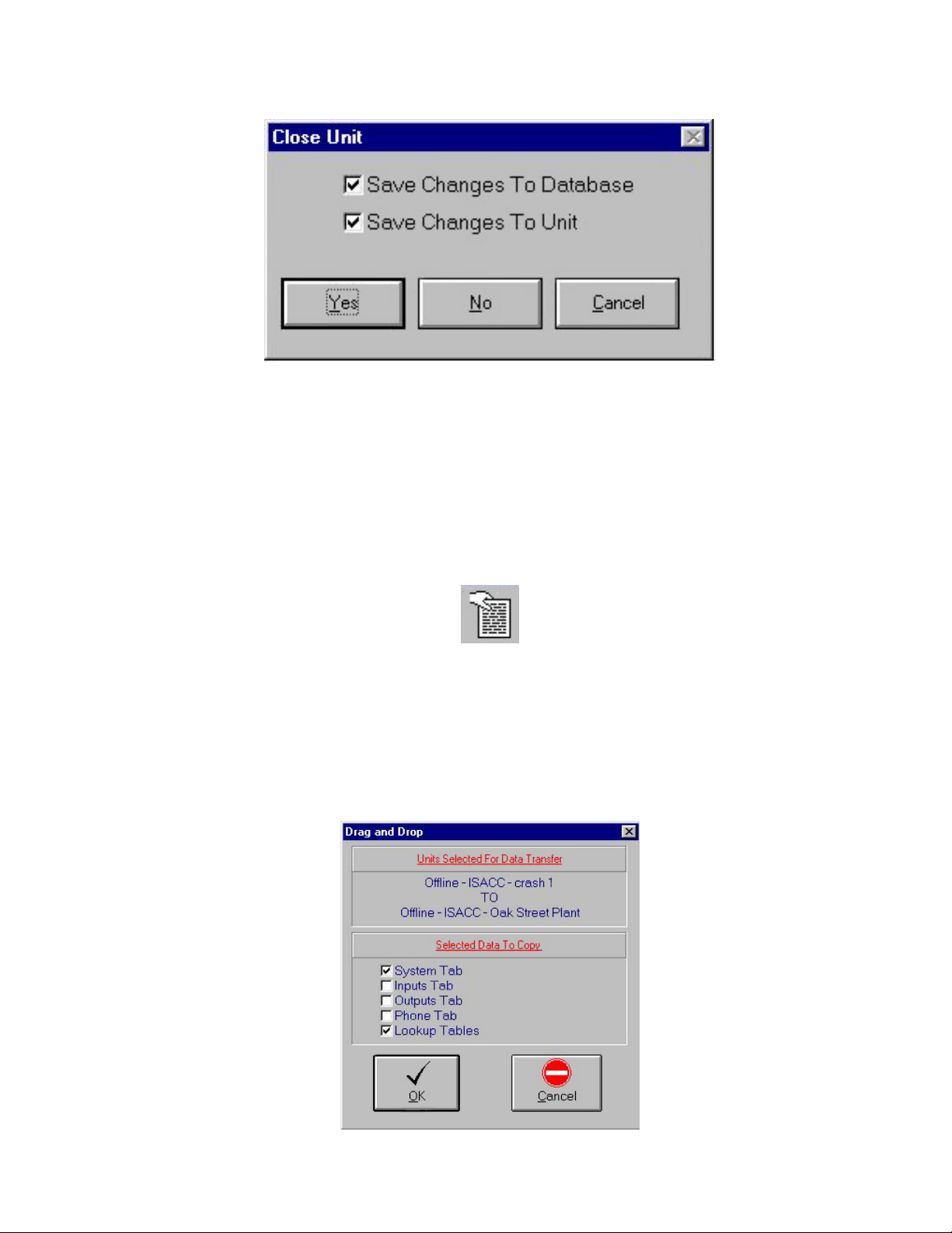
Closing a Unit
Click on Close from the File menu, or click the “Close” button on the toolbar.
When you close a unit and you have made programming changes, the ‘Close Unit’ form
appears. You will be given the option of saving your changes to the ISACC unit as well as to
the database on your PC.
Connecting to a Unit not in your Database
If you want to connect to an ISACC unit that is already programmed, but this unit is not in
your database, follow the instructions below.
If you know the exact Unit ID description, just follow the instructions for “Adding a New
Unit to Your Database” in this chapter. When you connect to the unit, the data mismatch box
will appeaer. Select “Overwrite Database with Unit Data.” Your PC database will now
contain the programming from the unit.
If you are unsure of the exact Unit ID description but you know the phone number and
password, you can connect to the unit and get the exact Unit ID. Start by creating a dummy
unit named Temp. follow the instructions for “Adding a New Unit to Your Database” in this
chapter, but use the name “Temp” for the Unit ID. Go online with the unit. A data mismatch
form will appear. Select “Ignore Mismatch and Edit Unit Data.” Go to the “Text Mode” tab.
Type “>show system” at the ISACC prompt. The Unit Identification will appear in the
listing. Write it down exactly as it appears. Close the connection without saving to the unit
or database. Delete the Temp unit. Now create a NEW unit using the exact Unit ID. When
you connect to the unit, the data mismatch box will appear. Select “Overwrite database with
Unit Data.” Your PC database will now contain the programming from the unit.
14
Page 15
Chapter Two: Configuring MANAGER
Copying Programming using Drag and Drop
Phonetics MANAGER for Windows is an MDI application that allows you to have several
different unit forms open at the same time. You can only be on-line with one ISACC unit at a
time so the other unit forms must represent off-line units. Drag and Drop has been implemented for data transfer between unit forms. To Drag ISACC parameters from one unit to
another, click on the icon of a hand holding a sheet of paper in the upper left hand corner of
the form.
NOTE: This icon exists only on the System, Inputs, Outputs, and Phone tabs. You must
have one of these tabs open in both units to perform Drag and Drop between units.
Keeping your mouse button depressed, move your mouse pointer over the tab of another unit
form until it transforms into an open hand dropping a page. Then release the button. Data
from the System, Inputs, Outputs, and Phone tabs can be copied from the first unit form to
the second. Releasing the mouse button will bring up the following form:
15
Page 16
ISACC Manager for Windows
The Drag and Drop form allows you to select the data to be copied. Click OK to proceed
with transferring the data between units.
On-line Programming
If you Open a Unit using either ‘Local’ or ‘Modem’ communication, you will be connected
directly to an ISACC unit. This on-line connection allows you to make programming
changes and load them into the unit immediately.
When using the MANAGER software to go on-line with a unit, the data you see on your
screen will reflect what the ISACC Unit currently holds only if you have maintained pro-
gramming settings between both database and unit. It is the user’s responsibility to keep
the data consistent between the database and the ISACC unit. While Manager software is
designed to prompt you to save changes in most instances, you should make a habit of al-
ways saving your programming changes to both the unit and database, no matter how minor
the change might be. Remember, if you are On-line with ISACC and you make a pro-
gramming change on the screen, you must send the updated data to the ISACC. The
software will automatically prompt you to save when you Close your connection; however,
you may also save the information immediately by clicking on the To Unit button or To
Database button on the toolbar. These features are also available on the Data Transfer menu.
When you use the TO UNIT/FROM UNIT and TO DATABASE/FROM DATABASE buttons, the Unit ID, Unit phone number, and password are not transferred or changed.
Off-line (Unit Database) Programming
If you Open a Unit using the ‘Unit Database’ selection, you can change a unit’s programming without actually connecting to the unit. All programming will be saved to the unit
database in your PC. The next time you open the unit using either ‘Local’ or ‘Modem’
communication, you’ll be able to replace the unit’s programming with your PC’s database
information. This feature is useful if you want to pre-program a unit before connecting to it.
Uploading Programming (copying programming information from your PC’s database to an
ISACC unit)
1. Open an on-line connection with a unit.
2. Select ‘To Unit’ from the ‘Data T ransfer’ menu, or click the ‘To Unit’ button on the
toolbar.
Downloading Programming (copying programming information from an ISACC unit to
your PC’s database)
1. Open an on-line connection with a unit.
2. Select ‘From Unit’ from the ‘Data Transfer’ menu, or click the ‘From Unit’ button
on the toolbar.
16
Page 17
Chapter Three: Programming
Chapter 3 Programming
MANAGER organizes all of ISACC’s programmable parameters into a fill-in-the-blank
format. Within a unit record, there are eight easy-to-read programming screens, referred to
as tabs. The tab titles are: System, Inputs, Outputs, Phone, C Programming, Real Time, Data
Logging, and Text Mode.
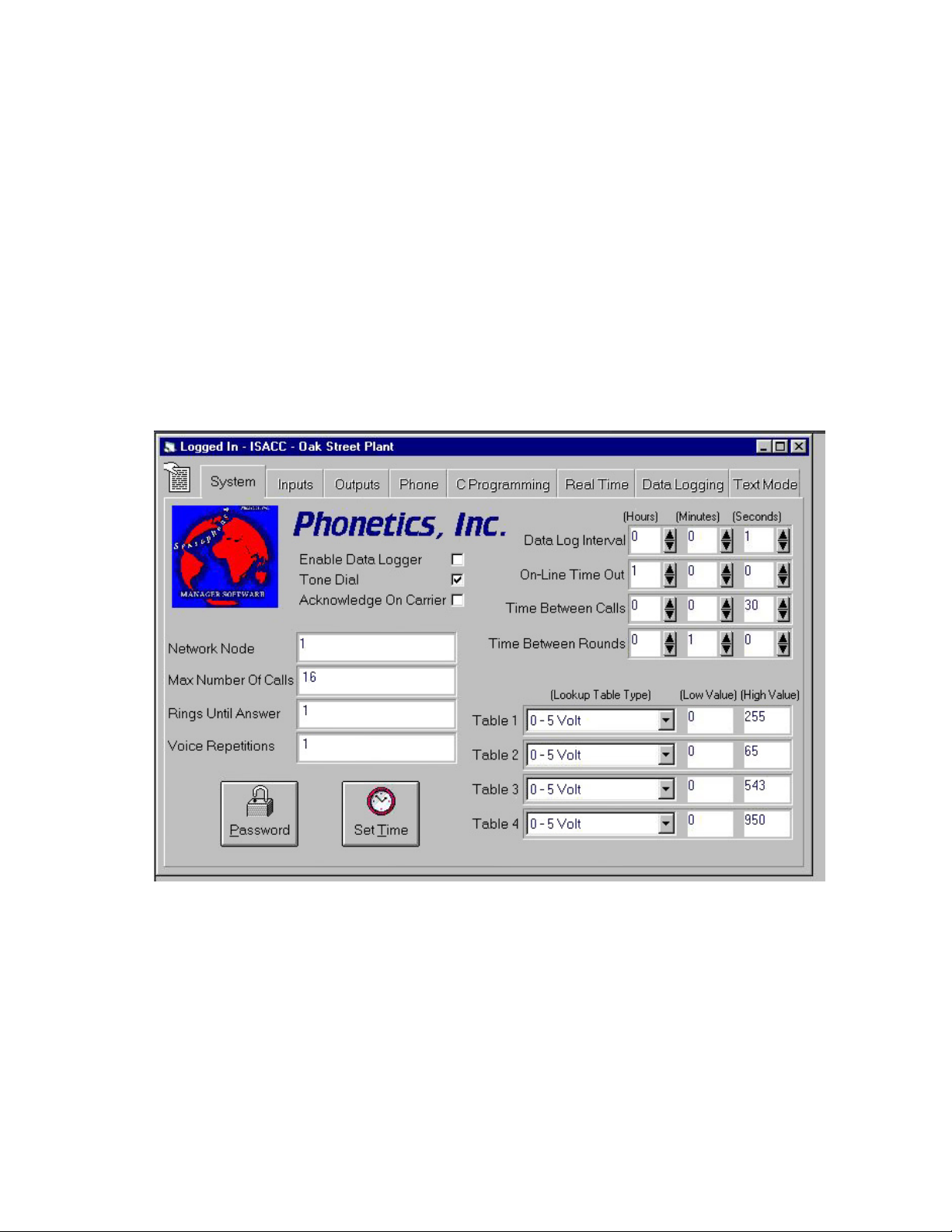
SYSTEM TAB
The System tab contains programming parameters that apply globally to the operation of the
unit.
Enable Data Logger - Check this box to enable ISACC’s Data Logging feature. The Data
Logger can record and store up to 512 logs. Each log contains the present value of all 16
inputs with a time stamp. Remember, the datalogger won’t start until you upload your
programming.
Tone Dial - ISACC can dial out using Touch-Tones or Pulses. Check this box to select Tone
dialing. If the box is not checked, ISACC will dialout using pulses.
17
Page 18

ISACC Manager for Windows
Acknowledge on Carrier - If this box is checked and ISACC makes an alarm call to a
computer, it will consider the alarm acknowledged when it detects a modem carrier signal. If
not, ISACC will expect an acknowledgment code before it will consider the alarm acknowledged. If you are going to use a PC running MANAGER software to receive alarm calls, you
must disable this feature.
Network Node - Up to 16 ISACC units may be networked together via the RS485 port. The
Network Node number identifies the ISACC unit in the network. This number may be from
0 to 15, the default is 1. If ISACC is not part of a network, its network node should be set to
1. When units are networked, the master must be set to 0.
Max Number of Calls - This is the total number of calls that ISACC will make in the event
of an alarm. ISACC will continue to call the eight Phone Numbers in sequence until the
alarm is acknowledged or the Max Number of Calls has been reached. The Max Number of
Calls parameter may be programmed from 0 to 9999
CAUTION: If Max Number of Calls is programmed to zero, ISACC will not dial out
at all.
Rings Until Answer - This is the number of rings that ISACC will wait before answering an
incoming call. The minimum number of Rings Until Answer is 1, the maximum is 15.
Voice Repetitions - This is the number of times ISACC will repeat the alarm message during
an alarm dialout phone call before requesting acknowledgment. The number of repetitions of
the alarm message may be from 1 to 255 for each phone call. The default is 3 repetitions.
NOTE: If the voice repetitions is set to 0 (zero), ISACC will not recite the alarm message.
Data Log Interval - This is the amount of time ISACC waits between making entries to the
Data Logger. The minimum time is 1 second and the maximum time is 18 hours. Use the up
and down arrow buttons to set the Data Log Interval.
NOTE: The Data Logger must be enabled to write data to the data logger, otherwise no data
will be logged.
On-Line Time Out - This parameter allows you to program the amount of time that ISACC
will wait before disconnecting during Text-Mode communication. When on-line with
ISACC in Text-Mode, the unit looks for communications inactivity. When the unit has not
received a command for the duration of the On-Line Time Out, ISACC will disconnect and
display the message TIME OUT on the screen.
NOTE: This parameter only affects communications in Text-Mode. If any of the
other Windows forms are displayed, ISACC MANAGER for Windows will terminate
the connection after a fixed time-out of 10 minutes. After this time period a warning
message will appear on the screen. You will have 30 seconds to acknowledge the
message and remain connected.
18
Page 19

Chapter Three: Programming
Time Between Calls - This is the amount of time ISACC will wait between dial-outs. The
minimum time is five seconds and the maximum is 273 minutes. Use the up and down arrow
buttons to set the Time Between Calls.
Time Between Rounds - This parameter is used to set the amount of time that a unit will
wait after calling all the Phone Numbers in its list before starting over again. The minimum
time is zero minutes. The maximum time is 273 minutes. Use the up and down arrow
buttons to set the Time Between Rounds.
Lookup Table Type - ISACC offers you the ability to create up to 4 linear lookup tables for
0-5V or 4-20mA analog input types. Use the drop down arrow to select either a 0-5V or 420mA Lookup Table Type.
Lookup Table Low Value - This is the low limit of the analog lookup table. Position the
cursor in the field and type a numerical value between -9999 and 9999.
Lookup Table High Value - This is the high limit of the analog lookup table. Position the
cursor in the field and type a numerical value between -9999 and 9999.
Set Time - This is used to set the date and time of ISACC’s internal clock. While on-line
with a unit, click the Set Time button and the ‘Set Unit Time’ form will appear. Position the
cursor in the date and time fields and enter the desired values. If you wish to transfer your
PC’ s internal time and date directly to ISACC, click the PC Date/Time button. Click ‘OK’
when finished.
NOTE: This feature is only available while on-line with a unit.
Password - This button is used to change ISACC’s data password. While on-line with a unit,
click the Password button. A form will appear prompting you to enter the current password.
If you don’t know the current password, you won’t be able to change it. Enter the current
password, click ‘OK’, and the ‘New Password’ form appears. Enter the new password under
both Password and Verification. The password can be up to 30 characters long. Next, choose
whether to save the password to disk. If this box is checked, MANAGER will automatically
enter the programmed password when a unit is opened. If this box is not checked, MANAGER will prompt you to manually enter the unit’s password when a unit is opened.
NOTE: This feature is only available while on-line with a unit.
19
Page 20
ISACC Manager for Windows
INPUTS TAB
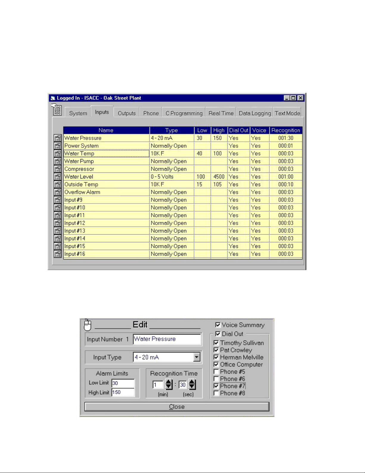
The Inputs tab allows you to view and program the input parameters for all 16 inputs. The
main form is shown below.
To program the input parameters, click the input’s ‘Edit’ button, located to the left of each
input. The selected input’s ‘Edit’ form will appear. When finished click Close.
20
Page 21

Chapter Three: Programming
Input Name - This is the descriptive name you provide to identify each input. The name can
be up to 16 characters long.
Input T ype - The input type is defined by this parameter. To program, select one of the
following 14 input types:
Normally Closed 10K F
Normally Open 10K C
Pulse Count Table 1
4 - 20 mA Table 2
0 - 5 Volts Table 3
2.8K F Table 4
2.8K C User Defined
Limits - If an input’s value goes below the low alarm limit or above the high alarm limit,
ISACC will dial out with an alarm. The Low and High Alarm Limits can be programmed
from -9999 to 9999. To set the Alarm Limits, position the cursor in the field and type in a
value.
Recognition Time - The Alarm Recognition Time is the length of time an alert condition
must exist continuously before ISACC considers it an actual alarm and initiates a response.
The recognition time is programmed in minutes and seconds by clicking the up and down
buttons or by positioning the cursor in the field and type in a value. The Alarm Recognition
Time can be from 0 seconds (recognized as 300 milliseconds) to 273 minutes. The default
value is 3 seconds.
Voice Summary - This parameter determines what information will be included in ISACC’s
status report during a voice dial-in. If Voice is checked for a particular input, that input’s
status will be included in the status report when you call in over the phone. If Voice is not
checked, that input’s status will be excluded from the report.
Dial Out - This allows you to enable the input for dialout and allows you to choose which of
the 8 phone numbers will be dialed in case of an alarm. To select a phone number for dial
out, check the appropriate box. If the ‘Dial Out’ box for the current input is not checked, the
Dial Out feature is disabled and no calls will be made if an alarm occurs on the input.
21
Page 22
ISACC Manager for Windows
OUTPUTS TAB
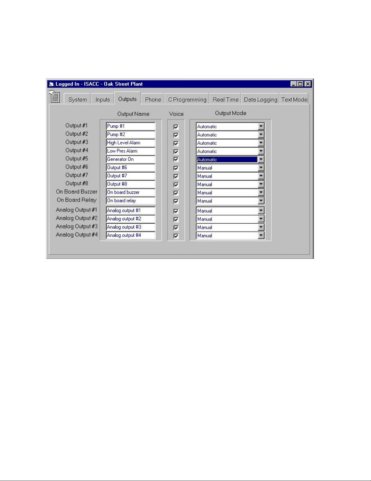
The Outputs tab allows you to program the output name, voice report status and mode of
output control.
Output Name - This is the descriptive name you provide to identify each input. The name
can be up to 16 characters long.
Output Mode - This parameter determines how the outputs are controlled. The choices are
manual and automatic. Manual output type means that the output is controlled by the user.
Automatic means that the output is controlled within a C program.
NOTE: For an output to work in a C program, its Type MUST be automatic.
Voice - This parameter determines what information will be included in ISACC’s status
report during a voice dial-in. If Voice is checked for a particular output, that output’s status
will be included in the status report when you call in over the phone. If Voice is not checked,
that output’s status will be excluded from the report.
22
Page 23
Chapter Three: Programming
PHONE TAB
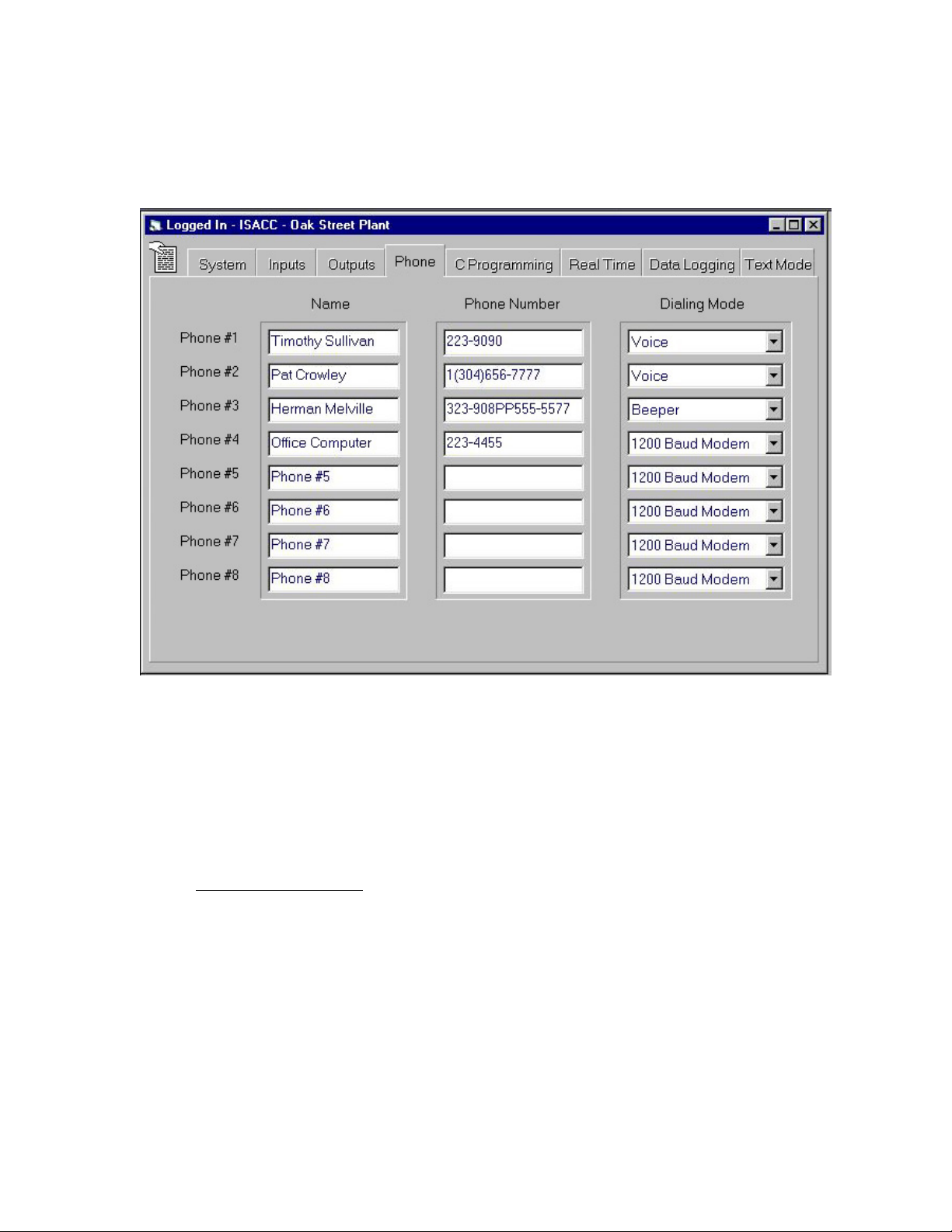
The Phone tab allows you to program the phone numbers that will be called when ISACC has
an alarm. The Phone Tab is pictured below:
Name - This is the descriptive name you provide to identify each dial-out contact person.
The name can be up to 16 characters long. To edit the name, click in the text box and type.
Phone Number - These are the numbers that ISACC will call in case of an alarm dialout.
The Phone Number can be up to 31 characters long. To edit the phone number, click in the
phone number text box and type.
Special Dialing Codes
In programming the Phone Numbers, four special dialing codes may be incorporated
to account for pauses and to wait for special phone line tones. The five dialing codes
are:
P = two-second pause
W = wait for dial tone
A = wait for answer
I = send input numbers in alarm
23
Page 24

ISACC Manager for Windows
Code P - This code tells ISACC to wait two seconds during the dialout. A twosecond pause may be placed anywhere in the Phone Number that a pause is desired.
It accounts for one character and may be used more than once.
Example: 9-P-1(601)555-7744 (if you need to dial 9 to get an outside line)
Code W - This code tells ISACC to wait until a dial tone is detected before dialing
the Phone Number. If, after ten seconds no dial tone is detected, ISACC will dial-out
automatically.
Example: 109-W-1(402)123-4432 (dial extension 109, wait for dialtone and dial the
number)
Code A - This code tells ISACC to wait for the phone to stop ringing before ISACC
continues. This is useful if you are calling a beeper and the beeper service does not
produce a tone when ready. If the phone number is called in voice mode, ISACC will
automatically wait until the phone is answered before speaking.
Example: 556-4433-A-(609)423-2222 (pager phone number)
Code I - This code tells ISACC to send the input number that has an alarm. It can
only be used if you are dialing out to a pager. After the call is received by the pager
company, the ‘I’ code instructs ISACC to send a two-digit number indicating which
input is in alarm.
Example: 1(301)665-8877-PP-444-5511-I (pager number with alarms)
Dialing Mode - Program the Dialing Mode by clicking on the down arrow of the selection
box and selecting the desired Dialing Mode. ISACC is capable of performing the following
types of dialout:
300 Baud Modem (data mode)
1200 Baud Modem (data mode)
2400 Baud Modem (data mode)
Voice
Beeper
External Modem
Data mode dialout is used when you wish to have your computer answer alarm calls. This
requires you to have your computer and modem on continuously and also have ISACC
Manager Software running in Receive Alarm Mode (see chapter on Receive Alarm Mode).
24
Page 25
Chapter Three: Programming
C PROGRAMMING TAB
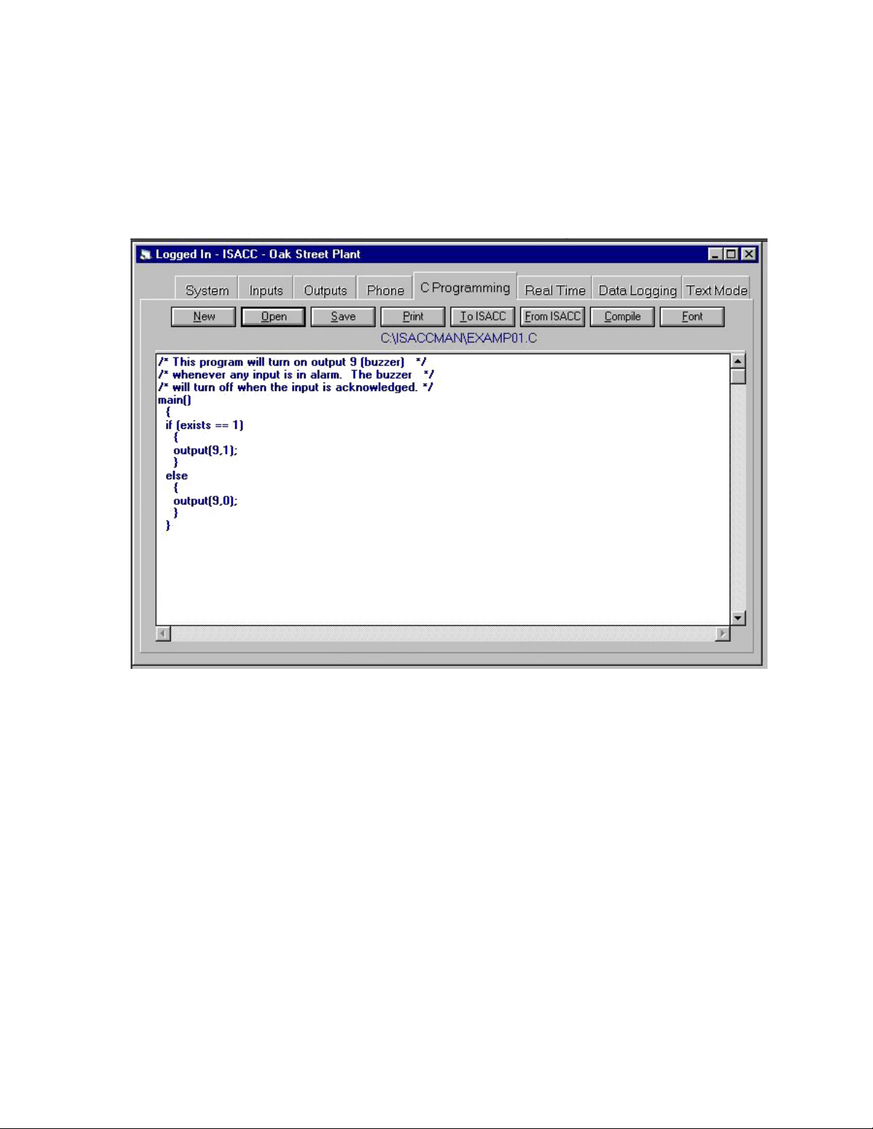
The C PROGRAMMING tab provides a user-friendly environment to write, edit, and manage your C programs. The toolbar buttons above the Editor screen provide access to all
available functions. For instruction on writing C programs, refer to Chapter 8 of the ISACC
Operator’s Manual. The following is a description of the functions of the C Programming
Toolbar buttons.
New - This will clear the editor screen so you can create a new C program. If there is already
a C program in the editor window, you will be prompted to save changes to it before it is
cleared.
Open - This will clear the editor screen and load a previously saved C program. If there is
already a C program in the editor window, you will be prompted to save changes to it before
it is cleared.
Save - This button allows you to name your program and save it as a file. Type the name you
want to give your program (“*.C” is the default). MANAGER will automatically tag your
program with the extension “.C” if you do not include an extension. Click ‘OK’ and MANAGER will save your program under that name and return you to the editor window. The
name of your program will be displayed below the toolbar buttons.
Print - Prints the C current program.
25
Page 26

ISACC Manager for Windows
To ISACC - Copies (uploads) the current C program into an ISACC unit.
NOTE: The “To ISACC” upload feature is only available while on-line with a unit.
From ISACC - Copies (downloads) the C program from an ISACC unit to the editor screen.
NOTE: This feature is only available while on-line with a unit.
Compile - This feature searches your program for errors and reports the number of global
variables detected. If a programming error is detected, the Compiler will provide an error
type and description along with the line number where it detected the error. It is possible to
pass the scan with no errors, but receive an error during a program run. A run time error
occurs when the syntax of a built-in function is incorrect. If the program compiled successfully, you will be asked if you wish to start the program. If you choose “OK,” you will be
asked to enter a program reload rate.
NOTE: The C-Program reload rate can be interrupted by the Real Time Download if
the download delay is set too short. The delay is programmable from the main menu
under Options>Real Time Settings. Be sure to set the delay to at least 5000 ms if you
will be using Real Time mode with a C-Program running.
Below is a list of compiling errors:
ERROR TYPE DESCRIPTION
0 Syntax
1 Semicolon expected
2 Unbalanced braces
3 Parentheses expected
4 While expected
5 Quote expected
6 Variable not found
7 Too many variables defined, limit is 127
8 Bracket expected
9 Compiled file too big
Font - This button allows you to change the attributes of the text displayed in the editor
window.
26
Page 27
Chapter Three: Programming
BLOCK FUNCTIONS
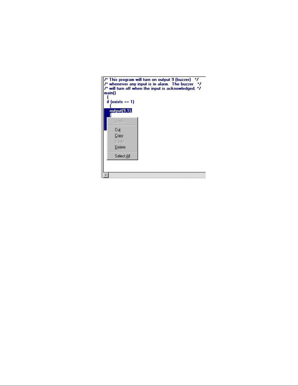
The following keys are called block functions. They allow you to cut and paste blocks of
programming text. An example is shown below:
Define a block - This function is used to select the section of your program that you want to
edit. A block selected for editing by highlighting the text. To use, position the cursor in your
program where you want to start the block. Hold down the left mouse button and drag it to
highlight a block of text. Once highlighted, the portion of text you want to delete, move or
copy is now ready to edit. To access the editing functions, place the cursor over the highlighted text and click the right mouse button (Windows 95 and NT only, if you’re using
Windows 3.x use the Alt - ? functions listed below). Manager’s editing functions are: Cut,
Copy, Paste, Delete, and Select All.
Cut (Alt - X) - This function removes the highlighted section of your program from the
screen and places it on the Windows clipboard. You may then use the Paste command to reinsert the cut block into your program. When used this way, you can move portions of your
program around, eliminating retyping.
Copy (Alt - C) - This function copies the highlighted section of your program from the
screen to the Windows clipboard. You may then use the Paste command to re-insert the
copied block into your program.
Paste (Alt - V) - This function is used to insert a Cut or Copied block into your program. To
use, position the cursor where you want to insert the block. Click the right mouse button to
access the editing functions and select Paste. The block will be inserted in the program at the
place you specified.
27
Page 28

ISACC Manager for Windows
Delete - This function deletes the highlighted section of your program.
Select All - This is used to quickly highlight your entire program.
KEYBOARD SHORTCUTS
Most of the C program editor’s block functions may be accessed using keyboard shortcuts.
Define - Shift+Arrow
Cut - Shift+Delete
Copy - Ctrl+Insert
Paste - Shift+Insert
Delete - Delete
CONTROL KEYS
The following are CONTROL keys. They help you to move around the Editor window.
Control Key Function
CTRL-Home Go to beginning of document
CTRL-End Go to end of document
CTRL-PageDown Go to bottom of screen
CTRL-PageUp Go to top of screen
CTRL-Home - This function will return the cursor to the beginning of your program. To
use, press CTRL + Home key.
CTRL-End - This function will take you to the end of your program. To use, press CTRL +
End key.
CTRL-PageDown - This command will position the cursor at the bottom of the screen. To
use, press CTRL + PageDown key.
CTRL-PageUp - This command will position the cursor at the top of the screen. To use,
press CTRL + PageUp key.
28
Page 29

Chapter Three: Programming
OTHER FUNCTION KEYS
The following are additional functions to help you to move around the Editor window.
KEY FUNCTION
End Go to end of line
Home Go to beginning of line
PageUp Go up one screen
PageDown Go down one screen
Arrow keys Cursor up, down, left, right
End - This key will take you to the end of a program line. To use, press End.
Home - This key will take you to the beginning of a line. To use, press Home.
PageUp - This key will take you up one page or screen. To use, press PageUp.
PageDown - This key will take you down one page or screen. To use, press PageDown.
Arrow keys - These keys are used to cursor one character up, down, left, or right.
29
Page 30
ISACC Manager for Windows
REAL TIME TAB
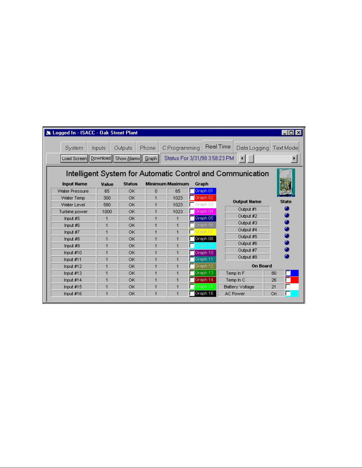
The Real Time tab allows you to monitor ISACC’s inputs in real time while you are on-line
with a unit. You will be able to watch input values change and see alarms as they occur. You
can make your own custom Real Time Screen using the Real Time Screen Builder (see the
chapter on “Real Time Screen Builder”). This is a separate program included with ISACC
Manager Software.
Real time ISACC data may be displayed two ways: the Real Time form or a real time graph.
The Real Time form is shown below:
Following is a description of the functions of the Real Time toolbar buttons.
Load Screen - This button allows you to load in a custom screen that was made with the Real
Time Screen Builder.
Download - In order to receive real time data from ISACC, you must click the Download
button while on-line with a unit. While the Download button is depressed, the display dial
spins to indicate that ISACC’s inputs are being monitored in real time. Information on all of
ISACC’s inputs is continuously transferred to the MANAGER software while the Download
button is depressed. To stop real time monitoring, click the Download button again.
NOTE: Downloading will start automatically when you first connect to a unit.
30
Page 31
Chapter Three: Programming
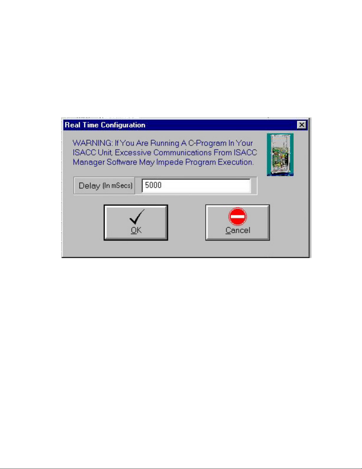
The Real Time display’s update speed depends on the delay time programmed on the Real
Time Settings form under Options from the main menu. The delay time is programmable in
milliseconds (i.e. 1000 milliseconds = 1 second). The minimum delay time is 0 milliseconds,
but this setting is only recommended if you are not running a C-Program. If you are running
a C-Program, a delay of 0 milliseconds will impede the execution of the C-Program, causing
it not to run at the programmed interval. To prevent this problem, set the delay to at least
5000 milliseconds or longer, depending on the run time of your C-Program and the baud rate
of your connection. Shown below is the Real Time Settings configuration form:
Show Alarms - This button will display all unacknowledged alarms that may exist.
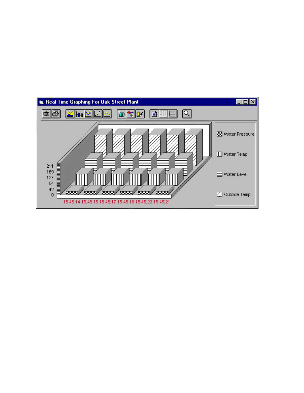
Graph - To include an input in a real time graph, you must first check the Graph Option
check box for that input. Each selected input will be drawn in a different color so that they
can be distinguished on the graph. Click the Graph button. Next, click Download to begin
the real time data transfer. You may add or remove an input from the real time graph during
the data transfer by checking the Graph Option check box for that input.
The Graph feature has many options for displaying your data such as line graph, bar chart 3D, etc… Experimentation is the best way to determine the format most applicable to your
application. If you come upon a part of the graph that you wish to print, simply click on the
‘Printer button’ on the graph toolbar. The GRAPH feature also allows you to graph stored
real time records. Manager’s Real Time function also works like a mini Data Logger. In
addition to displaying the unit’s real time data, MANAGER will also store up to 100 real
time records in your PC. As the unit displays input information in real time, the scroll bar on
the top of the form will slowly move to the right. Once it scrolls all the way to the right,
Manager will have received 100 records, but now the oldest real time records are being
overwritten by the newest ones. When the Download button is clicked again, real time
31
Page 32
ISACC Manager for Windows
monitoring will stop and your PC will retain the most recent 100 real time records for playback. To playback the stored real time data, use the left and right scrollbar arrows. The
scrollbar can be useful if you are trying to locate the time of a particular event or if you just
want to view trends of the conditions being monitored. You may select an input to graph by
checking the Graph Option box for that input. Note that once you close the connection, the
real time data will be deleted.
32
Page 33
Chapter Three: Programming
DATA LOGGING TAB
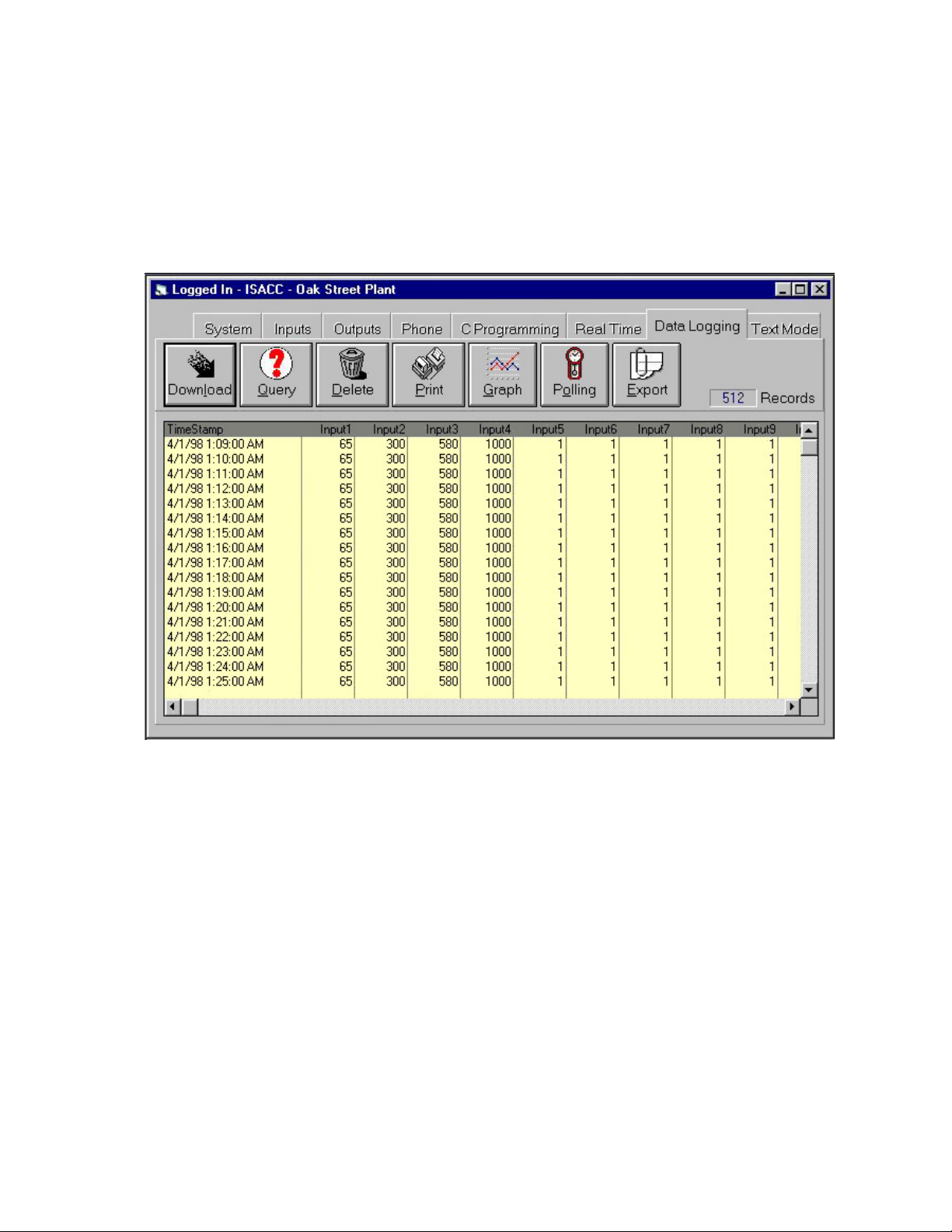
The Data Logging tab allows you to retrieve, store and view information collected from an
ISACC’s datalogger. MANAGER software will collect the data and store it in a database on
your PC.
Following is a description of the functions of the Data Logging toolbar buttons:
Download - While on-line with a unit you can instantly download the contents of a unit’s
Data Logger by clicking on DOWNLOAD. This will instruct ISACC to send all of its
datalogger contents to the PC. Every time a unit’s Data Logger is downloaded, MANAGER
software adds the new information to that unit’s database in your PC. It also checks for and
filters out duplicate Data Log records. When finished, MANAGER will prompt you to clear
ISACC’s datalogger. Choosing OK will clear the datalogger in ISACC. By choosing Can-
cel, ISACC will retain all of its datalogger information and simply start to overwrite the
oldest records once it is full. Once you select OK or Cancel, Manager will display the data
that was just downloaded.
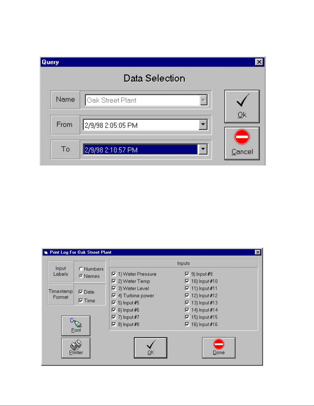
Query - The QUERY button allows you to selectively search and view Data Log information
in the PC’s database by entering start and end dates in the ‘From’ and ‘To’ fields. If you click
on the down arrows, the time and dates for all of the records in the database will be displayed
in chronological order. Select the time and dates you want to query and click on OK. The
query grid may be adjusted to show more inputs on the screen by dragging the lines separat-
33
Page 34
ISACC Manager for Windows
ing each input name closer to each other. The scroll bars may also be used to move around
the grid and view all of the information.
Delete - The DELETE button will delete the visible records in the current Query.
Print - The print button allows you to print the datalogger information that is currently
displayed on the Query grid. Clicking on the print button opens a form for selecting print
options including: input value headings (by input name or number), time stamp options (date,
time or both), which inputs to print, and selectable fonts & point sizes. Your printer may
even give you additional options such as printing in portrait or landscape modes. Landscape
will print and 8.5" x 11" page sideways so that if you are printing many inputs you can get
most, if not all of them, on a page. You will have to experiment with fonts and point sizes to
optimize printing results with your equipment.
34
Page 35
Chapter Three: Programming
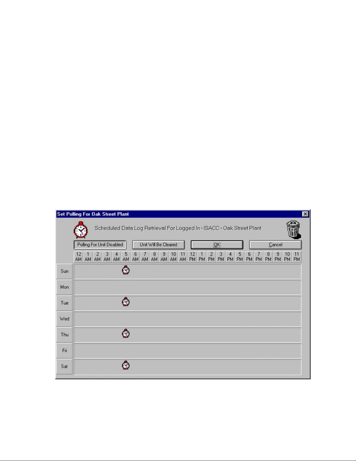
Polling - Polling is an automated method of having MANAGER contact your ISACC unit(s)
and retrieve datalogger information on a programmed time schedule. To set-up the polling
feature click on the POLLING button. The time schedule is configured by grabbing a clock
from the top of the screen and dragging it to the appropriate day and time and then releasing
the clock. Polling can only be performed on the hour. You may set as many days and times
as necessary to ensure that you don’t miss any records. This depends on how often ISACC is
programmed to log data. For example, if ISACC is logging data every 5 minutes, you would
have to retrieve the data every 42 hours (512 records x 5minutes / 60min per hr). To delete a
polling time, click on the polling clock you want to delete, then drag and drop it into the trash
can at the top of the screen. Click on the ‘Polling Enable/Disable’ button to turn polling on or
off. The button marked “Unit will be Cleared” is the default setting to clear the datalogger in
the ISACC after polling. If you wish to retain the data after polling, click on this button to
change it to “Unit Will Not Be Cleared.” (Clearing after polling will reduce the download
time because MANAGER will only have to download the amount of data in the datalogger.)
Once you have set up the polling schedule you must enable the polling feature from the
Options category on the main menu. Note that in order for the polling feature to work you
must: (a) Have the program password saved to disk for the unit you are polling and (b) have
the MANAGER software running continuously on your PC, 24 hours a day, 7 days a week.
35
Page 36
ISACC Manager for Windows
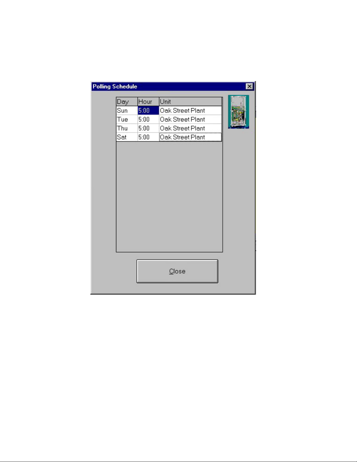
You can view the polling schedule for all units by clicking on Polling Schedule in the Options menu. A sample screen is shown below:
36
Page 37
Chapter Three: Programming
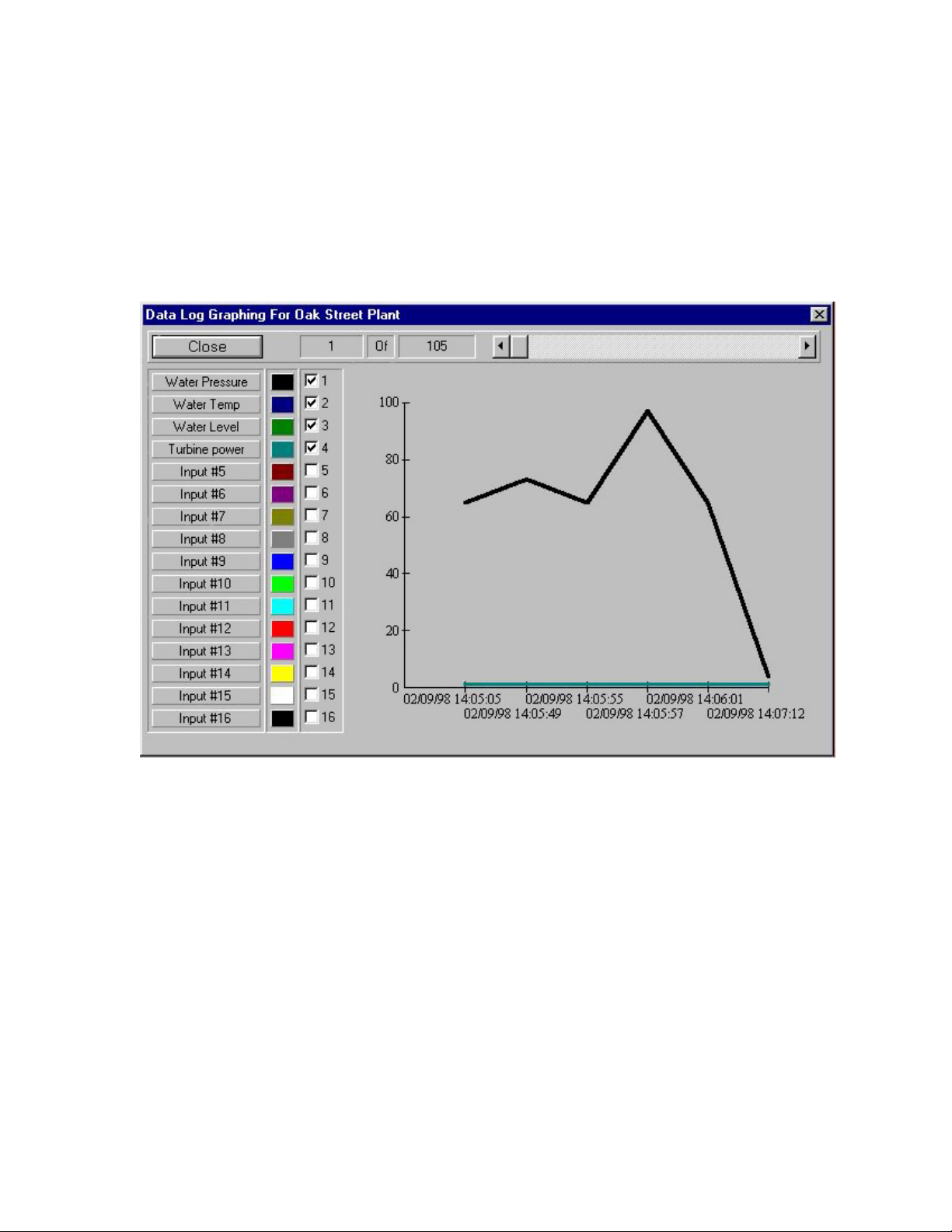
Graph - This feature allows you to graph the information that is currently displayed in the
Query grid. You may select an input to view on the graph by checking the input’s selection
box. Each selected input may be drawn in a different color so that they can be distinguished
on the graph. Select an input’s display color by clicking on the input’s color box until the
desired color appears. The scroll bar at the top of the form moves the graph left and right.
This feature can be useful if you are trying to locate the time of a particular event or if you
just want to view trends of the conditions being monitored.
Export - The EXPORT feature creates a comma-delimited text file of the data displayed in
the Query grid. This formats the data so that it can be used in spreadsheets such as Microsoft
Excel, Lotus 123, or Quattro. Refer to the documentation on these programs to import a
comma-delimited text file.
37
Page 38

ISACC Manager for Windows
TEXT MODE TAB
Text mode allows you to use the original ISACC programming language as detailed in the
ISACC Operator’s Manual. This mode is required to program or access some parameters not
available from the Windows interface. These parameters include:
- manually turning outputs on or off
- manually setting the analog output values
- checking ISACC diagnostics
Refer the ISACC Operator’s Manual for more information on the text mode commands. You
will receive warning messages as you enter and leave Text Mode asking you to upload/
download changes. It is recommended that you perform the Upload or Download so that
none of your programming changes will be lost going into and out of Text Mode.
38
Page 39
Chapter Four: Receive Alarm Mode
Chapter 4 Receive Alarm Mode
Receive Alarm Mode is the communication link between ISACC and your computer when
you are not there. You must have a modem for MANAGER to receive alarm phone calls
from ISACC. MANAGER will answer the incoming alarm calls, record the alarm information in the PC’s database, then either acknowledge the alarm or not depending on your
programming. Note that in order for the Receive Alarm Mode feature to work you must have
MANAGER software running continuously on your PC, 24 hours a day, 7 days a week.
AUTO ANSWERING
To engage Receive Alarm Mode, select Receive Alarms from the Options menu. MANAGER will set your modem to Auto Answer mode. Note that Receive Alarm Mode cannot
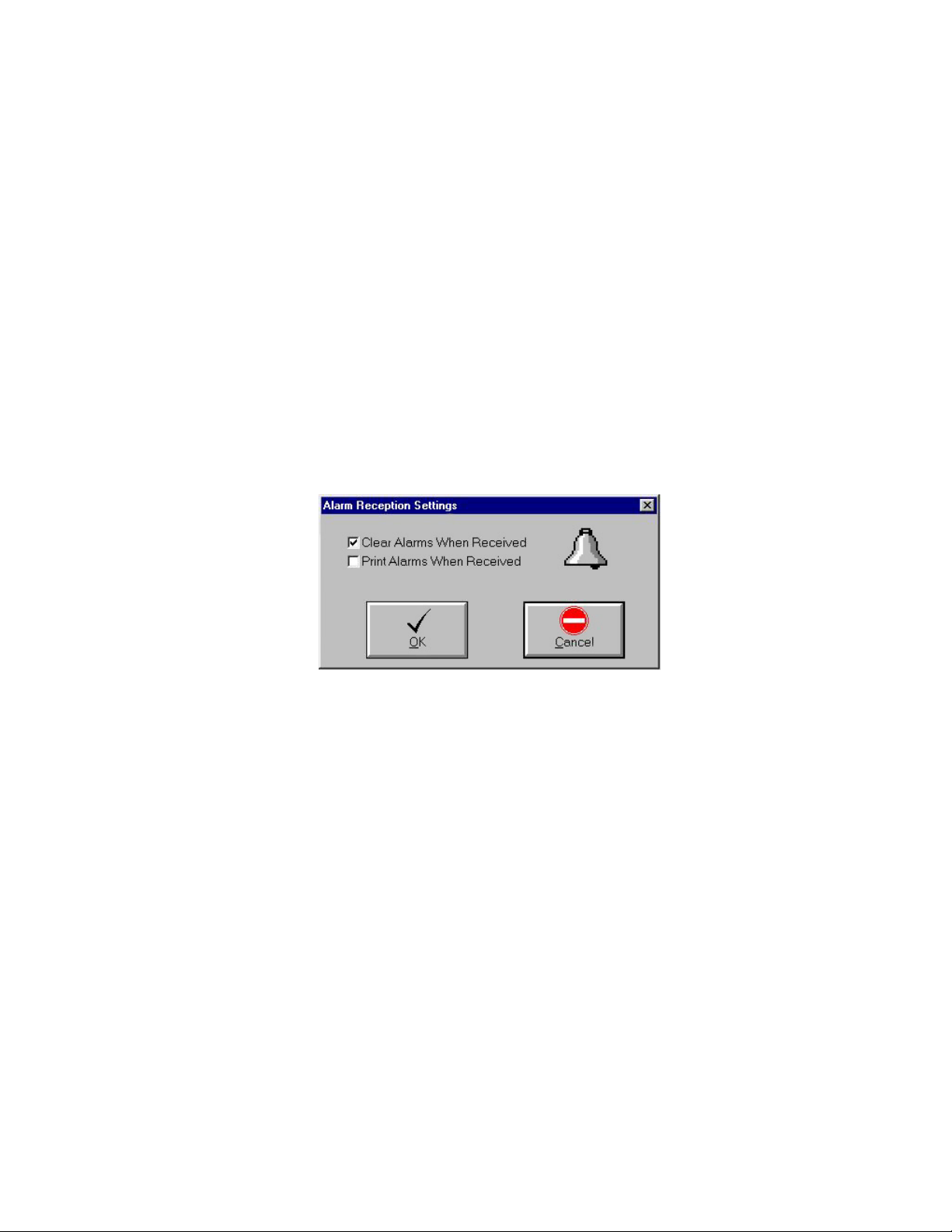
be enabled while you are on-line with a unit. From the Options Menu, select Alarm Recep-
tion Settings to see the following form:
You may choose to clear or print the alarms when they’re received. The Default setting will
clear the alarms.
NOTE: The automatic Clear Alarms feature is not the same as ISACC’s Acknowledge-On-Carrier feature. If Acknowledge-On-Carrier is selected, as soon as ISACC
detects a modem carrier tone during a dial out alarm call, it acknowledges the alarm.
If MANAGER is programmed to receive alarms, ISACC should NOT be programmed to Acknowledge-On-Carrier (see System Tab in Chapter 3). If it is, the PC
will not keep a record of the incoming alarm call because ISACC just acknowledged
the alarm so there is nothing to record.
The RECEIVE ALARMS form will run minimized in the bottom left corner of your PC’S
screen. Your PC is now ready to receive alarm calls from ISACC units.
39
Page 40
ISACC Manager for Windows
VIEWING ALARM INFORMATION
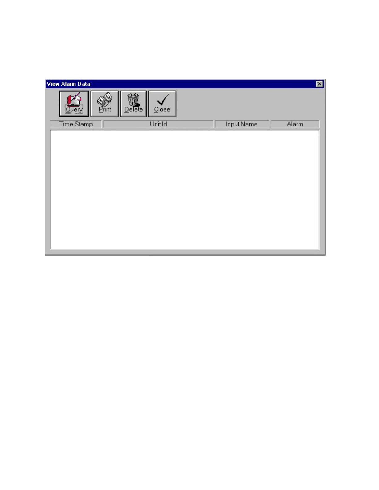
To view the received alarm messages, select View Alarm Data from the Options menu. The
VIEW ALARM DATA form will appear. A sample is shown below:
The following is a description of the functions of the View Alarm toolbar buttons:
Query - The Query button allows you to selectively search and view Alarm information in
the PC’s database by picking a unit and selecting start and end dates.
Print - The Print button allows you to print the Alarm Data information currently displayed
in the Query grid.
Delete - The Delete button will delete selected Alarm Data records from the PC’s database.
To delete a record, highlight it first by clicking on it. Multiple records can be highlighted by
dragging the cursor up or down while holding the left mouse button. Click the Delete button
to delete the highlighted records.
40
Page 41
Chapter Five: Real Time Screen Builder
Chapter 5 Real Time Screen Builder
The ISACC MANAGER Real Time Screen Builder is a design tool for customizing the
display screen shown on ISACC MANAGER’s Real Time programming tab. It is a separate
program that is included with ISACC MANAGER Software.
When you first open ISACC MANAGER’s Real Time tab, the default monitoring screen is
displayed. The screen is composed of two types of display entities, text fields and graphics.
Text fields display input and output information such as name, status, and value. Graphics
are used to display output states or pictures of your process. They may be inserted anywhere
in the monitoring screen to make it more visually appealing.
To create your own Real Time Screen, exit Manager and run Screen Builder. When the Real
Time Screen Builder program is run, the Properties window and the Design toolbar appear in
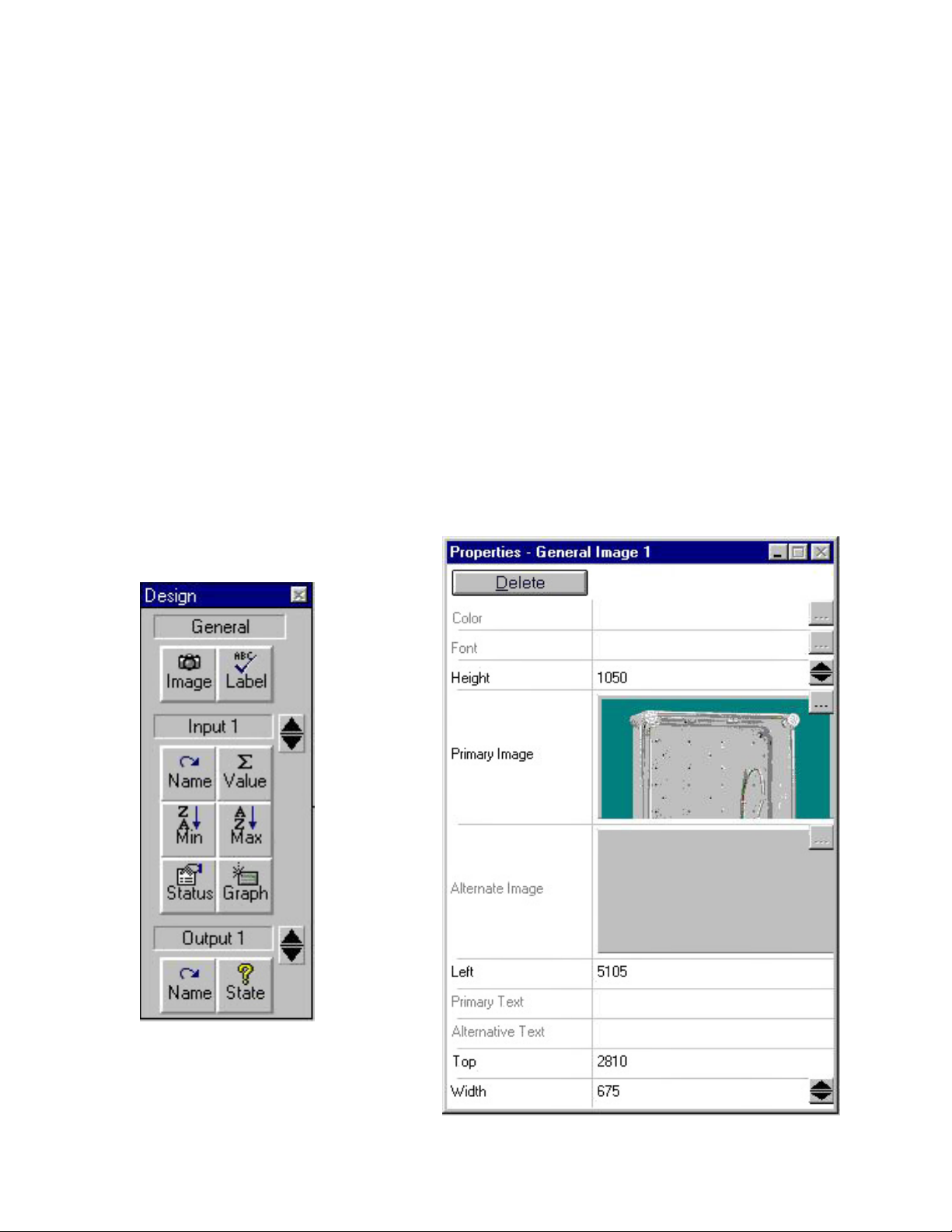
addition to four buttons across the top of the screen labeled Clear, Open, Save and Exit. The
rest of the screen is the design palette. This where you will place images and labels to create
your screen. Shown below are the Design Toolbar and Properties Window:
41
Page 42

ISACC Manager for Windows
The Design toolbar contains all possible entities (images, labels, values, names,…). There
are 3 main headings for entities: General, Input, and Output. Input and Output entities are
associated with a particular input or output while General entities are just generic images and
labels that may be added for convenience. When working with the Input and Output entities
you must select the specific input or output with the up/down arrows before you drag the
entity to the screen. Listed below is a description of each of the features on the Design
Toolbar and Properties Window.
General Images - A graphic entity used for adding images such as pictures or company
logos to sections of the monitoring screen. MANAGER’s default general image is the Phonetics company logo, but any windows bitmap (.bmp) file may be used as an image entity.
General Labels - A text field used for adding titles to sections of the monitoring screen.
The default Real Time tab monitoring screen contains the general labels ‘ISACC Real Time’,
‘Input Name’, ‘Value’, ‘Status’, ‘Minimum’, ‘Maximum’, ‘Graph’, ‘Output Name’, ‘State’,
and ‘System’.
Input Name - A text field that displays the name of the input. The name displayed is the
same name as that programmed from the Inputs tab in the MANAGER program.
Input Value - A text field that displays the current value of the input. For Normally Open
and Normally Closed input types, an Open input will display a value of 1, and a Closed input
will display a value of 0, however, you can also have a text description appear for Normally
Open and Normally Closed inputs. With the Value field selected, type in the ‘Open’ condition text in the Primary text field on the Properties window and the ‘Closed’ condition text in
the Alternate text field.
Input Min - A text field that displays the lowest value an input has reached.
Input Max - A text field that displays the highest value an input has reached.
Input Status - A text field that displays the current status of an input.
Input Graph - A selection field that allows the user to choose to include an input in a graph.
Output Name - A text field that displays the name of the output. The name displayed is the
same as that programmed from the Outputs tab in the Manager program.
Output State - A graphic entity that displays the state of an output. The output state graphic
is actually made up of two images, primary and alternate. The primary image is displayed
when the output is OFF and the alternate image is displayed when the output is ON.
MANAGER’s default primary image is a blue light, and it’s default alternate image is a red
light. However, any windows bitmap (.bmp) file may be used as an image entity.
42
Page 43

Chapter Five: Real Time Screen Builder
Building your Screen
1. Click on the desired entity from the Design Toolbar.
2. Hold the left mouse button down to drag the entity to the desired location and drop it.
Note: To place an Input or Output entity, you must first use the up and down arrows
to select the desired input or output.
Moving an entity (text field or graphic):
1. Click on the desired entity.
2. Hold the left mouse button down to drag the entity to a new location and drop it.
Deleting an entity (text field or graphic):
1. Click on the desired entity.
2. Click the Delete button at the top of the Properties Window.
Modifying Fonts
1. Click on a text field. The Properties Window will display the attributes of the selected
field.
2. Click the browse button on the right side of the Font line in the Properties Window.
3. Select the desired font, style, and point size, then click OK.
Modifying a text field size
1. Click on a text field. The Properties Window will display the attributes of the selected
field.
2. Click the up or down arrows on the right side of the Height and Width fields in the
Properties Window until the field is the desired size.
Selecting an image
1. Drag and drop an image from the Design Toolbar or click on an image on the screen.
2. On the properties toolbar, click on the browse button on upper right-hand corner of the
primary image field. Select an image file and click OK.
Modifying an image size
1. Click on a an image. The Properties Window will display the attributes of the image.
2. Click the up or down arrows on the right side of the Height and Width fields in the
Properties Window until the image is the desired size.
43
Page 44

ISACC Manager for Windows
Modifying Graph Options colors
1. Click on a Graph Option field. The Properties window will display the attributes of
the selected field.
2. Click the browse button on the right side of the Color field in the Properties Window.
3. Select the desired color, then click OK.
NOTE: The Graph Option color selected for an input will be used to represent that
input when MANAGER creates a real time graph.
Selecting Output State Primary and Alternate images
1. Click on an Output State image. The Properties Window will display the attributes of
the selected image.
2. Click the browse button on the right side of the Primary or Alternate image line in the
Properties window.
3. Select an image bitmap (.bmp) file, then click OK.
Note: MANAGER’s default primary image is a blue light, and it’s default alternate
image is a red light. However, any windows bitmap (.bmp) file may be used as an
image entity.
44
Page 45

Appendix A: Tr oubleshooting
Appendix A T roubleshooting
Installation Problems
• A common problem during the installation process occurs when the setup program tries to
update a windows file (usually a DLL, OCX, or VBX) while that file is in use. If a message pops up telling you that a certain file is in use, the easiest way around the problem is
to press the Ignore button. That particular file will not be updated, but the MANAGER
Software should still run. The MANAGER Software will just be missing some of the
newer enhancements contained in the latest version of that DLL, OCX, or VBX. If you
press the ignore button during the installation process and the MANAGER software does
not run properly, you may wish to rename the file that caused the conflict and then reinstall
MANAGER.
Communication Problems
• I have a laptop plugged into ISACC’s RS232 port but I can’t get on-line?
Check the Local Port setup and make sure you have the correct baud rate and com port
selected. Remember, ISACC defaults to 9600 baud.
• I try to go on-line through the modem but it never seems to connect?
Check the Modem Setup on the Communications menu. Make sure you are using the
right setup string. Sometimes this requires trying different strings to find the right one for
your modem. If necessary you may have to contact your modem manufacturer to get the
setup string. Your setup string must disable error correction and data compression in order
to communicate with ISACC.
Programming problems
• When I enable datalogging on the System Tab and then try to Download on the Datalogger
Tab, I get the message “No records were downloaded.”
When you made changes on the System Tab you probably didn’t send your programming
to ISACC. You must click the To ISACC button after making programming changes in
order for them to be uploaded to ISACC.
• I have MANAGER programmed to poll but it never collects any data?
There are several things to check:
- Make sure that you have the programming password saved to disk.
- Make sure polling is enabled for that ISACC unit on the Polling screen.
- Make sure you enabled polling from the Options menu.
- Make sure your modem is on.
45
Page 46

ISACC Manager for Windows
- Make sure your ISACC unit has the date and time programmed
- Make sure ISACC’s datalogger is running.
- Make sure your modem communications is properly setup.
• I have MANAGER running in Receive Alarm Mode but I didn’t get a message when an
alarm occurred?
There are several things to check:
- Make sure your modem communications is setup properly.
- Make sure Acknowledge On Carrier is set to ‘No’ on the System Tab.
- Make sure you enabled Receive Alarm Mode from the Options menu.
- Make sure your modem and computer are on.
• Can I run in Polling Mode and Receive Alarm Mode at the same time?
Yes. Manager will perform polling at the programmed time periods and when its not
polling it will Receive Alarms.
46
 Loading...