

Page 1
○○○○○○○○○○○○○○○○○○○○○○○○○○○○○○○○○○○○○○○○○○○○○
®
Sensaphone
ISACC
Operator’s
Manual
version 3.49
○○○○○○○○○○○○○○○○○○○○○○○○○○○○○○○○○○○○○○○○○○○○○
Page 2

Every effort has been made to ensure that the information in this document is complete, accurate and
up-to-date. Phonetics, Inc. assumes no responsibility for the results of errors beyond its control.
Phonetics, Inc. also cannot guarantee that changes in equipment made by other manufacturers, and
referred to in this manual, will not affect the applicability of the information in this manual.
© 1997 by Phonetics, Inc.
Version 3.49, September, 2000.
Written and produced by Phonetics, Inc.
Please address comments on this publication to:
Phonetics, Inc.
901 Tryens Road
Aston, PA 19014
Updates and addendums to this manual can be found on the Support pages of our web site: http://
www.sensaphone.com
Sensaphone
®
is a registered trademark of Phonetics, Inc.
Touch Tone™ is a registered trademark of AT&T.
Page 3

SAFETY INSTRUCTIONS
○○○○○○○○○○○○○○○○○○○○○○○○○○○○○○○○○○○○○○○○○○○○○
IMPORTANT SAFETY INSTRUCTIONS
Your ISACC has been carefully designed to give you years of safe, reliable performance. As
with all electrical equipment, however, there are a few basic precautions you should take to
avoid hurting yourself or damaging the unit:
• Read the installation and operating instructions in this manual carefully. Be sure to save
it for future reference.
• Read and follow all warning and instruction labels on the product itself.
• To protect the ISACC from overheating, make sure the unit is not subject to direct
sunlight. Do not place on or near a heat source, such as a radiator or heat register.
• Be certain that your power source matches the rating listed in the AC power requirements of this manual. If you’re not sure of the type of power supply to your facility,
consult your dealer or local power company.
• Do not allow anything to rest on the power cord. Do not locate this product where the
cord will be abused by persons walking on it.
• Do not overload wall outlets and extension cords, as this can result in the risk of fire or
electric shock.
• Never push objects of any kind into this product through ventilation holes as they may
touch dangerous voltage points or short out parts that could result in a risk of fire or
electric shock.
• To reduce the risk of electric shock, do not disassemble this product, but return it to
Phonetics' Customer Service, or other approved repair facility, when any service or
repair work is required. Opening or removing covers may expose you to dangerous
voltages or other risks. Incorrect reassembly can cause electric shock when the unit is
subsequently used.
• If anything happens to indicate that your ISACC is not working properly or has been
damaged, unplug it immediately and follow the procedures in Appendix E for having it serviced. Return the unit for servicing under the following conditions:
1. The power cord or plug is frayed or damaged.
2. Liquid has been spilled into the product or it has been exposed to water.
3. The unit has been dropped, or the cabinet is damaged.
4. The unit doesn’t function normally when you’re following the operating instructions.
CAUTION
Safety Instructions Page 3
Page 4

To Reduce the Risk of Fire or Injury to Persons, Read and Follow these Instructions:
1. Use only the following type and size batteries:
6V 3.0AH sealed lead-acid rechargable
2. Do not dispose of the batteries in a fire. The cell may explode. Check with local codes
for possible special disposal instructions.
3. Do not open or mutilate the batteries. Released electrolyte is corrosive and may cause
damage to the eyes or skin. It may be toxic if swallowed.
4. Exercise care in handling batteries in order not to short the battery with conducting
materials such as rings, bracelets, and keys. The battery or conductor may overheat and
cause burns.
5. Do not mix old and new batteries in this product.
6. Battery service should be performed by qualified personnel only.
Page 4 Sensaphone® ISACC Instruction Manual
Page 5

Table of Contents
TABLE OF CONTENTS
○○○○○○○○○○○○○○○○○○○○○○○○○○○○○○○○○○○○○○○○○○○○○
ISACC MANUAL 3.4.9
SAFETY INSTRUCTIONS ........................................................................ 3
IMPORTANT SAFETY INSTRUCTIONS................................................................................ 3
CHAPTER 1: INTRODUCTION .............................................................. 9
PROGRAMMING ISACC ..................................................................................................... 9
LEARNING TO USE ISACC .................................................................................................. 9
ABOUT THE MANUAL ........................................................................................................9
IMPORTANT! ....................................................................................................................10
CHAPTER 2: INSTALLATION ................................................................ 11
COMPLETE PACKAGE INSTALLATION (FGD-5000) .......................................................... 11
UNPACKING ISACC ..........................................................................................................11
GROUNDING WRIST STRAP ............................................................................................ 11
OPERATING ENVIRONMENT ...........................................................................................12
MOUNTING ISACC........................................................................................................... 12
STRAIN RELIEF .................................................................................................................. 12
POWERING ISACC............................................................................................................13
ADDITIONAL SURGE PROTECTION ................................................................................ 13
BACKUP BATTERY .............................................................................................................13
LITHIUM BATTERY............................................................................................................ 14
TURNING ISACC ON........................................................................................................14
RESET BUTTON ................................................................................................................. 14
BUZZER ............................................................................................................................. 14
PHONE LINE INSTALLATION ........................................................................................... 14
BOARD LEVEL INSTALLATION (FGD-5100) ..................................................................... 15
UNPACKING ISACC ..........................................................................................................15
GROUNDING WRIST STRAP ............................................................................................ 15
OPERATING ENVIRONMENT ...........................................................................................15
MOUNTING ISACC........................................................................................................... 15
POWERING ISACC............................................................................................................16
AC SUPPLY REQUIREMENTS: ............................................................................................ 16
AC SUPPLY CONNECTIONS: ............................................................................................ 16
DC SUPPLY REQUIREMENTS: ...........................................................................................17
DC SUPPLY CONNECTIONS:............................................................................................ 17
GROUNDING ISACC ........................................................................................................ 18
BACKUP BATTERY .............................................................................................................18
LITHIUM BATTERY............................................................................................................ 18
TURNING ISACC ON........................................................................................................19
RESET BUTTON ................................................................................................................. 19
BUZZER ............................................................................................................................. 19
v
Page 6

Sensaphone® ISACC Instruction Manual
PHONE LINE INSTALLATION ........................................................................................... 19
FCC REQUIREMENTS ........................................................................................................ 20
CANADIAN DEPARTMENT OF COMMUNICATIONS NOTICE......................................... 21
CHAPTER 3: COMMUNICATION SETUP ............................................. 23
SETUP FOR PC .................................................................................................................. 24
LOCAL COMMUNICATION THROUGH RS232 PORT...................................................... 24
SETUP FOR TERMINAL...................................................................................................... 27
LOCAL COMMUNICATION THROUGH RS232 PORT...................................................... 27
REMOTE COMMUNICATION VIA MODEM...................................................................... 30
ISACC RS232 SPECIFICATIONS ......................................................................................... 31
NETWORK WIRING .......................................................................................................... 31
CHAPTER 4: INPUTS ............................................................................ 33
HOW THE INPUTS WORK ................................................................................................ 33
INPUT TERMINAL BLOCK ................................................................................................. 35
WIRING SENSORS TO THE INPUTS .................................................................................. 35
SHIELDED WIRE ................................................................................................................ 36
LENGTH OF WIRE............................................................................................................. 37
INPUT MODULES ............................................................................................................. 37
To use the 4-module rack with ISACC:.............................................................................................. 37
To wire the logic I/O (right side) to ISACC: ...................................................................................... 38
To wire the field I/O (left side) to the input device:..........................................................................38
DIP CONNECTOR FOR A 16-MODULE RACK .................................................................. 38
To use the 16-module rack: ............................................................................................................... 39
ISACC INPUT SPECIFICATIONS........................................................................................ 40
INPUT MODULE SPECIFICATIONS .................................................................................. 40
AC INPUT MODULE (FGD-0018): .................................................................................... 40
DC INPUT MODULE (FGD-0017): .................................................................................... 40
CHAPTER 5: OUTPUTS ........................................................................ 41
HOW THE OUTPUTS WORK ............................................................................................ 41
OUTPUT TERMINAL BLOCKS ........................................................................................... 41
WIRING THE MECHANICAL RELAY .................................................................................. 42
To wire a device to the mechanical relay using an ISACC power supply:.......................................... 42
To wire a device to the mechanical relay using an external power source: ....................................... 42
WIRING THE DIGITAL OUTPUTS..................................................................................... 43
WIRING THE ANALOG OUTPUTS.................................................................................... 49
OUTPUT SPECIFICATIONS ............................................................................................... 49
DIGITAL: ........................................................................................................................... 49
ANALOG: .......................................................................................................................... 49
RELAY: ............................................................................................................................... 49
BUZZER: ............................................................................................................................ 50
SOLID STATE RELAY SPECIFICATIONS ............................................................................. 50
AC OUTPUT MODULE (FGD-0015):................................................................................. 50
DC OUTPUT MODULE (FGD-0016): ................................................................................ 50
HIGH POWER SOLID STATE RELAY (FGD-0020): ............................................................. 50
CHAPTER 6: POWER SUPPLIES ............................................................ 51
vi
Page 7

Table of Contents
CHAPTER 7: PROGRAMMING ............................................................. 53
KEYWORDS....................................................................................................................... 53
SYSTEM ............................................................................................................................. 54
CLOCK .............................................................................................................................. 56
INPUTS.............................................................................................................................. 56
ITYPE ................................................................................................................................. 57
TABLE ................................................................................................................................ 59
LIMITS ............................................................................................................................... 60
RECOGNITION ................................................................................................................. 61
ALARMS ............................................................................................................................ 62
DIALOUT .......................................................................................................................... 62
OUTPUTS .......................................................................................................................... 63
ONAME ............................................................................................................................. 64
PHONE .............................................................................................................................. 65
SELECTION........................................................................................................................ 67
VOICE ............................................................................................................................... 68
LOGGING .........................................................................................................................69
NETWORK.........................................................................................................................70
VARIABLES ........................................................................................................................ 71
STAND ALONE COMMANDS ........................................................................................... 72
RESET................................................................................................................................. 72
CLEAR................................................................................................................................ 72
PATCH ............................................................................................................................... 73
HELP .................................................................................................................................. 73
EXIT ................................................................................................................................... 74
DATA ................................................................................................................................. 74
123 .................................................................................................................................... 74
DIAG ................................................................................................................................. 75
CHAPTER 8: C PROGRAMMING ......................................................... 77
SPECIFICATIONS............................................................................................................... 77
ABOUT THE C LANGUAGE ............................................................................................... 77
STRUCTURE ..................................................................................................................................... 78
EDITING COMMANDS ..................................................................................................... 82
INSERT ............................................................................................................................................. 82
DELETE ............................................................................................................................................. 83
ERASE ............................................................................................................................................... 83
LIST .................................................................................................................................................. 83
STAND ALONE COMMANDS ........................................................................................... 84
COMPILE .......................................................................................................................................... 84
RUN ................................................................................................................................................. 84
START & STOP .................................................................................................................................. 84
C LANGUAGE KEYWORDS ............................................................................................... 86
PREDEFINED VARIABLES................................................................................................... 89
MONTH, DAY, YEAR, HOURS, MINUTES & SECONDS ................................................................... 89
EXISTS & UPTIME ............................................................................................................................. 89
FUNCTION LIBRARY ........................................................................................................ 91
ALARM .............................................................................................................................. 92
DATA ................................................................................................................................. 92
ENABLE ............................................................................................................................. 93
vii
Page 8

Sensaphone® ISACC Instruction Manual
INPUT ............................................................................................................................... 94
IS_ALARM ......................................................................................................................... 95
NETWORK.........................................................................................................................96
OUTPUT............................................................................................................................ 97
OUT_SPEC......................................................................................................................... 98
PUTNUM........................................................................................................................... 98
PUTS.................................................................................................................................. 99
RESET............................................................................................................................... 100
RELOAD .......................................................................................................................... 101
SET_INPUT ...................................................................................................................... 102
ARRAYS ........................................................................................................................... 103
SAMPLE PROGRAM: ....................................................................................................... 103
ERROR HANDLING ........................................................................................................ 106
DIFFERENCES BETWEEN STANDARD C AND ISACC C .................................................. 107
PROGRAMMING EXAMPLES .......................................................................................... 109
COMMON ISACC PROGRAMMING ERRORS................................................................. 112
CHAPTER 9: OPERATION .................................................................. 115
HOW THE UNIT WORKS ................................................................................................ 115
ALARM DIALOUT - VOICE MODE.................................................................................. 115
ALARM DIALOUT - DATA MODE ................................................................................... 116
ALARM DIALOUT - BEEPER ........................................................................................... 117
CALL PROGRESS ............................................................................................................. 117
STATUS REPORT - VOICE MODE .................................................................................... 117
VOICE MODE OUTPUT CONTROL ................................................................................ 118
STATUS REPORT - DATA MODE...................................................................................... 118
DATA LOGGER ................................................................................................................ 118
EXTERNAL MODEM ........................................................................................................ 118
CHAPTER 10: GLOSSARY................................................................... 121
APPENDIX A: CHECKING YOUR SENSAPHONE
FOR PROPER OPERATION .......................................... 123
APPENDIX B: ENGINEERING SPECIFICATIONS ................................ 125
APPENDIX C: BOARD LAYOUT ......................................................... 131
APPENDIX D: MOUNTING I/O DEVICES .......................................... 133
APPENDIX E: ACCESSORIES .............................................................. 139
APPENDIX F: RETURN FOR REPAIR .................................................. 141
WARRANTY ....................................................................................... 143
viii
Page 9

Chapter 1: Introduction
CHAPTER 1
○○○○○○○○○○○○○○○○○○○○○○○○○○○○○○○○○○○○○○○○○○○○○
INTRODUCTION
ISACC is a unique device that puts monitoring, alarm, and control capabilities all in one
system. It can monitor equipment and environmental conditions using 16 universal inputs. In
addition, these inputs can be programmed to switch up to 8 digital outputs and four analog
outputs in any combination.
Along with control, ISACC offers comprehensive communication. When an alarm occurs,
ISACC can dial up to 8 phone numbers and communicate in voice or data with its built-in
1200 bps modem.
One advantage ISACC has over other similar systems is that it is an all-in-one package. There
are no additional components to buy to complete the system, and ISACC's programming
flexibility provides the control you need to get the job done.
PROGRAMMING ISACC
Even with all of these features, ISACC is easy to use. A terminal or PC is all that is required to
communicate and program, locally or remotely. Phonetics also includes a Windows software
package, ISACC Manager for Windows, to help you take full advantage of ISACC's powerful
capabilities.
Text Mode programming is also available with simple keywords or stand-alone commands.
ISACC prompts for everything that is necessary, so you will have the unit up and running in
no time!
ISACC also offers the ability to create your own programs in the C language. It is resident
within the unit and is easy to use.
LEARNING TO USE ISACC
Reading this manual will help you become familiar with ISACC and its programming. This
will enable you to use the unit to its fullest potential. As you read this manual, consider your
specific installation and application.
If there are any questions or problems, contact:
PHONETICS, INC.
901 Tryens Road
Aston, PA 19014
(610) 558-2700 Fax: (610) 558-0222
www.sensaphone.com
ABOUT THE MANUAL
The ISACC Instruction Manual is composed of the instructions you need to use ISACC. You
should thoroughly read the manual to establish a basic understanding of the system and keep it
as a reference.
9
Page 10

Sensaphone® ISACC Instruction Manual
IMPORTANT!
Phonetics now includes a software package to work with ISACC using the Windows operating
system, it is called ISACC MANAGER for Windows and it will work with Windows 3.x,
95 and NT. This software makes ISACC even easier to use, and even more powerful. Some of
ISACC MANAGER’s features include:
AUTOMATIC POLLING - ISACCs can be polled on a programmable schedule
to retrieve the data logger.
INFORMATION MANAGEMENT - The PC can store and maintain all
programming information, data logger activity, and alarm activity for one or more
ISACCs.
ON-LINE HELP - All programming screens feature on-line help to provide
information that is pertinent to the parameters you are programming.
REAL TIME SCREEN - The software allows you to build a custom screen that
includes the input and output values you want displayed. You can also include your
own bitmap graphics for even greater customization. A separate application called
Real Time Screen Builder is included for this purpose.
For more information on the ISACC MANAGER for Windows Software Package, contact
Phonetics at (610)558-2700.
10
Page 11

Chapter 2: Installation
CHAPTER 2
○○○○○○○○○○○○○○○○○○○○○○○○○○○○○○○○○○○○○○○○○○○○○
INSTALLATION
This chapter explains the unpacking and installation of ISACC, both the complete package
(FGD-5000) and the board level product (FGD-5100). The complete package system is
mounted in a NEMA-4 ABS plastic enclosure with 18 VDC rechargeable battery backup. The
board-level unit is provided with a mounting kit so that you can mount the system properly
in another enclosure, etc. It is important that this chapter be read thoroughly and followed
very carefully before operating ISACC. Instructions for the complete package follow. For
instructions on installing the board level product, turn to page 15. Refer to Appendix B for a
diagram of the ISACC board layout.
COMPLETE PACKAGE INSTALLATION (FGD-5000)
UNPACKING ISACC
ISACC is shipped in specially designed packaging so that no damage will occur during shipment. When unpacking the unit, be careful not to damage the equipment or the box. It is
recommended that the packaging be saved for future use.
Within the packaging will be a Warranty Registration Card. Please take the time to fill
this out and mail. The Limited 1 Year Warranty is explained in the back of this manual.
CAUTION
ISACC is a sensitive electronic device. Personnel and work area should be grounded
before handling this device. Do not install ISACC near strong electrostatic, electromagnetic, magnetic or radioactive fields, i.e. generators, huge motors, pumps, or
turbines. Do not attach the power supply cord to building surfaces.
GROUNDING WRIST STRAP
Enclosed with the product is a Disposable Grounding Wrist Strap. It is provided to help
control and prevent the possibility of damage due to static electricity.
To use the grounding wrist strap, unwrap the strap to expose the adhesive. Wrap this end
around your wrist. Unwrap the rest of the strap and peel the liner away from the copper foil,
located at the opposite end. Attach the copper foil to the steel back panel in the ISACC
enclosure. NOTE: The grounding wrist strap is for static control. It will not reduce or
increase the risk of receiving electrical shock.
11
Page 12
Sensaphone® ISACC Instruction Manual
OPERATING ENVIRONMENT
ISACC should be mounted and operated in a clean, dry environment. If this is not possible,
NEMA 4 conduit hubs should be installed to seal ISACC off from the hazardous environment.
The temperature range that ISACC can operate in is 32°F to 120°F (0°C to 49°C).
MOUNTING ISACC
When you receive ISACC, there will be a PC Board (ISACC) mounted inside an ABS plastic
enclosure rated at NEMA 4, 4X, 12 and 13. You will also find the ISACC Instruction Manual,
a Communication Hookup Kit and ISACC Communication Software.
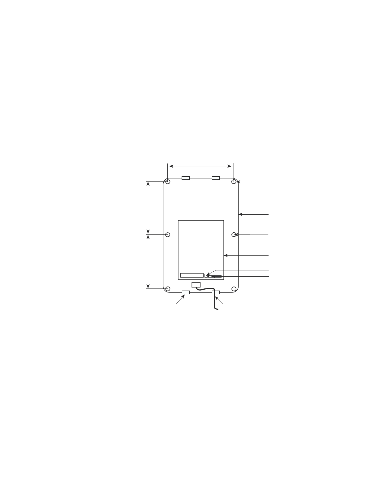
Carefully remove ISACC from the box. The mounting holes are located under the six plastic
screws. Carefully remove them and the clear top cover to mount the enclosure. Decide where
you will be mounting ISACC and drill holes according to the diagram below.
10"
.27" diameter
10.5"10.5"
strain relief clamp
Mounting ISACC enclosure
power cord
enclosure
mounting holes under
plastic screws
PC board (ISACC)
phone receptacle
RS232 port
After the holes have been drilled, you can mount the enclosure. Reinstall the top cover after
installation is complete.
STRAIN RELIEF
Strain relief clamps are provided in the ISACC enclosure to prevent wiring from being pulled
from the circuit board or damaged when passing through the enclosure. To use the strain
relief, thread wires through the clamp and clear rubber bushing. Position the bushing in the
clamp and tighten the screws on either side so that the wiring does not move.
12
Page 13

Chapter 2: Installation
top plate
clamp screw
bottom plate
clear rubber bushing
wiring
Strain relief clamp
POWERING ISACC
IMPORTANT: Before applying power to ISACC, the ON-OFF switch must
be in the OFF position. The ON-OFF switch is located to the right of the
acrylic panel, below the power supply terminal block.
ISACC is pre-wired with a three prong cord that can be plugged into any 117VAC
outlet. The power supply specification for the ISACC circuit board is 20 to 24
Volts AC, 50 or 60 Hz. This is applied through the two terminals labeled 24 AC.
ISACC is earth grounded. This is done to help protect it from the possible effects
of lightning strikes in or around the immediate area. A wire is connected from the
terminal labeled EG to the third leg of the power cord. The steel panel on the
bottom of the enclosure is also connected to earth ground for safety.
ADDITIONAL SURGE PROTECTION
It is recommended that additional surge protection be obtained for the power and
telephone lines, particularly if ISACC will be installed in a lightning-prone area.
Additional surge protection is available through Phonetics. Contact the Sales
Department for details.
BACKUP BATTERY
ISACC has three 6VDC rechargeable batteries wired in series. The total backup
battery voltage is 18VDC and offers a minimum of 3.5 hours and a maximum of
15 hours backup time. The actual battery performance is dependent upon what
external devices are wired to the 5V, 12V, 15V and 20V power supplies. If ISACC
is not powering any external devices, backup time will be 15 hours.
When the battery is configured for recharge, ISACC supplies a constant charge of
20.4 VDC when main power is present. To recharge the battery backup, go to the
SIP header at location P11 on the PC board. (P11 is located between the power
supply terminal block and the ON-OFF switch.) Using needlenose pliers, move
the shunt to the recharge position. See diagram below.
RECHARGE
NC
P11
Battery configured for recharge
NOTE: Have battery serviced by qualified service personnel only.
13
Page 14

Sensaphone® ISACC Instruction Manual
LITHIUM BATTERY
The lithium battery provides backup to the RAM and to the real-time clock, it's function is to
retain the time and programming if the power fails and backup battery is exhausted. On the
circuit board, the lithium battery is located under the acrylic safety panel on the right side. To
activate the battery, pull the paper strip out of the battery clip. The lithium battery is a
CR2430, 3 Volts, 270 mAhr. It will provide battery backup for approximately 2 years. Note:
The lithium battery will not keep ISACC operational.
TURNING ISACC ON
Now that ISACC has power, the ON-OFF switch may be turned on. The ON-OFF switch is
located on the right side of the circuit board below the power supply terminal block. ISACC’s
buzzer will sound briefly. The “power” LED will come on and be constant and the “pulse”
LED will blink steadily. The “phone” LED will not be lit.
When the unit is turned off, it is disabled. Programming parameters are retained by the 3V
lithium battery. In the off position, the 3V lithium battery is in use, however 18V battery
backup is not.
RESET BUTTON
Under the acrylic safety panel on ISACC’s PC board is a reset button. This is provided to
manually reset the unit. The button can be pressed by pushing a pen or thin object through
the hole provided. When the reset button is pressed, the PC board stays powered, but the
system is reset. None of the unit's programming will be affected by resetting the unit. Anything that ISACC recognizes as an alarm will be acknowledged and all dial out processes will
be halted.
BUZZER
Located on the PC board is a buzzer. When ISACC is turned on or reset, this buzzer will go
on briefly and then go off. The buzzer may also be used as a local audible alarm. It is considered OUTPUT9 in the programming of the parameters and the C program.
PHONE LINE INSTALLATION
ISACC must be hooked up to an analog phone line so that it can dial out for an alarm. On
the PC Board there is an RJ11C phone jack. It is located at one end of the PC BOARD and
is labeled PHONE (board location P3) . Connect ISACC to a standard 2 wire phone line.
ISACC dials using pulse or tone, with loop start only. ISACC will recognize ringer frequencies from 16 to 60 Hz.
IMPORTANT: Never install telephone wiring during a lightning storm. Never install
telephone jacks in wet locations unless the jack is specifically designed for wet locations.
Never touch uninsulated telephone wires or terminals unless the telephone line has been
disconnected at the network interface. Use caution when installing or modifying telephone lines.
14
Page 15

Chapter 2: Installation
BOARD LEVEL INSTALLATION (FGD-5100)
This section explains the unpacking and installation of a board level ISACC. For installation
instructions of a complete package ISACC (FGD-5000), turn to page 11. It is important that
this chapter be read and followed very carefully before operating ISACC.
UNPACKING ISACC
ISACC is shipped in specially designed packaging to eliminate damage during shipment.
When unpacking the unit, be careful not to damage the equipment or the box. It is recommended that the packaging be retained for future use.
Within the packaging will be a Warranty Registration Card. Please take the time to fill this
out and mail. The Limited 1 Year Warranty is explained in the back of this manual.
CAUTION: ISACC is a sensitive electronic device. Personnel and work area should be
grounded before handling this device. Do not install ISACC near strong electrostatic, electromagnetic, magnetic or radioactive fields. Do not attach the power supply cord to building
surfaces.
GROUNDING WRIST STRAP
Enclosed with the product is a Disposable Grounding Wrist Strap. It is provided to help
control and prevent the possibility of damage due to static electricity.
To use the grounding strap, unwrap the strap to expose the adhesive. Wrap the adhesive
around your wrist. Unwrap the rest of the strap and peel the liner away from the copper foil,
located at the opposite end. Attach the copper foil to an earth-grounded object. NOTE: The
grounding wrist strap is for static control. It will not reduce or increase the risk of receiving
electrical shock.
OPERATING ENVIRONMENT
ISACC should be mounted and operated in a clean, dry environment. The recommended
temperature range that ISACC should operate in is 32°F to 120°F (0°C to 49°C).
MOUNTING ISACC
When you receive ISACC, there will be a PC Board (ISACC), an instruction manual, and a
Mounting Hardware Kit. Inside the Mounting Hardware Kit are the following:
• 4 Hollow Nylon Spacers
• 4 #8-32 1˘” Machine Screws
• 4 #8 ˚" Wood Screws
• 4 Nylon Washers
• 4 #8-32 Hex Nuts
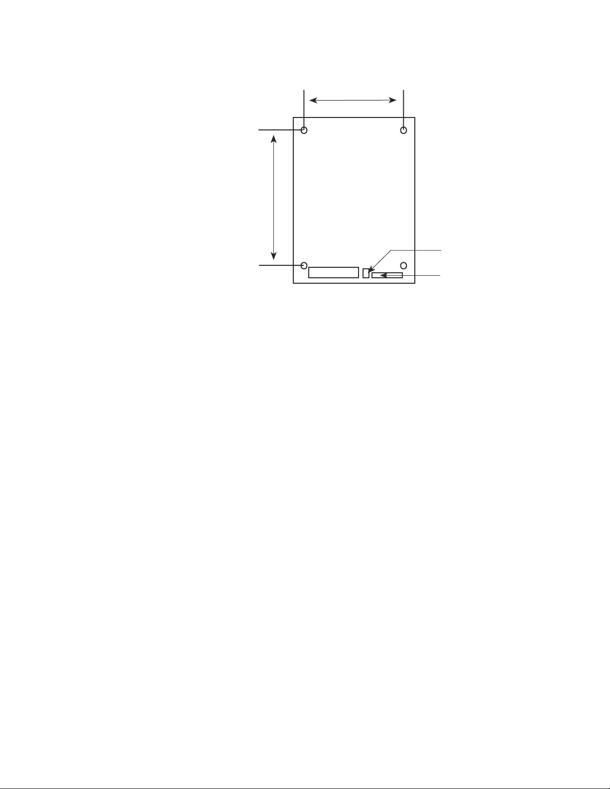
Carefully remove ISACC from the bubble pack. Decide where you will be mounting ISACC
and drill holes according to the diagram on the next page. The circuit board dimensions are
8" by 11".
15
Page 16
Sensaphone® ISACC Instruction Manual
7.5"
9"
phone
receptacle
RS232
port
Mounting ISACC circuit board
After the holes have been drilled, mount the board with the hardware provided. Use a nylon
washer between the board and the screw, and a nylon spacer between the board and mounting
surface. Both wood screws and machine screws have been provided for your convenience.
POWERING ISACC
IMPORTANT: Before applying power to ISACC, the ON-OFF switch must be in the
OFF position. The ON-OFF switch is located to the right of the acrylic panel, below the
power supply terminal block.
Located on the board is a terminal block labeled POWER. The power supply specification for
ISACC is 20 to 24 Volts AC, 50 or 60 Hz. This is applied through the two terminals labeled 24
AC.
You may use either an external AC power supply or an external DC power supply. Follow the
requirements and connection instructions below exactly so that problems and/or damage do
not occur. Three manufacturers of AC transformers that are compatible with ISACC are
Magnetek Triad (#F6-20), Thordarson (#FP-507), and Stancor (#P8661).
CAUTION: To avoid the danger of shock or damage to the unit, only qualified
personnel should wire and service the power supply.
AC supply requirements:
1. The voltage range for powering ISACC is 20 to 24 VAC.
2. The AC supply should be able to provide a minimum of 1.5 Amp at the required
voltage.
AC supply connections:
16
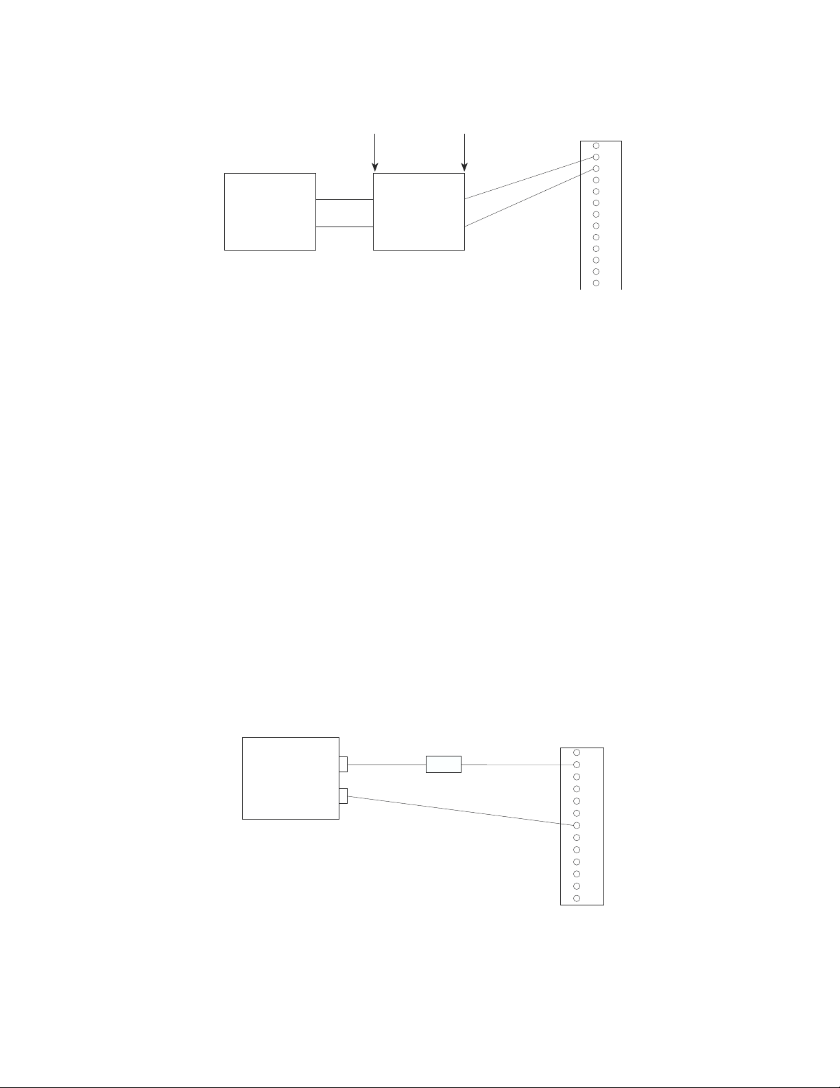
1. Wire the primary side of the 20 - 24 VAC transformer to the 120 VAC supply.
2. Wire the secondary side of the 20 - 24 VAC transformer to the terminals marked
24AC on the ISACC POWER terminal block.
Page 17
primary secondary
Chapter 2: Installation
EG 24 24 BAT C 20V C 15V C 12V C 5V C
AC AC
120 VAC
supply
DC supply requirements:
1. The voltage range for powering ISACC is 24 to 28VDC. If the voltage is lower
than 24VDC, the batteries will not fully charge. If the voltage is over 28VDC, excess
heat will be generated in the power supply and components may fail.
2. The DC supply should be able to provide a minimum of 1.5 Amp at the required
voltage.
3. The negative terminal on the DC supply must be either floating or connected to
"Earth Ground." If it is not, you will create a ground differential between ISACC,
your computer, and your sensors that may seriously damage these devices.
4. The positive terminal should have a 1.5 Amp Slo Blo fuse in-line between the
supply and ISACC. This is required because the fuse on the circuit board will be
bypassed with the new wiring.
20 - 24 VAC
1.5 A
transformer
Wiring an AC power supply to ISACC
POWER
DC supply connections:
1. Connect the negative wire from the DC supply to one of the common terminals
on the POWER terminal block.
2. Connect the positive wire from the DC supply (with the in-line fuse) to the terminal marked 24AC that is directly to the right of the EG terminal.
See diagram next page.
24 -32VDC
power supply
+
1.5 Amp
fuse
-
Wiring a DC power supply to ISACC
EG 24 24 BAT C 20V C 15V C 12V C 5V C
AC AC
POWER
17
Page 18

Sensaphone® ISACC Instruction Manual
GROUNDING ISACC
ISACC should be earth grounded by connecting a true earth ground to the terminal labeled
EG. This is not essential for ISACC to operate, but this will help protect against the possible
effects of lightning strikes in or around the immediate area.
BACKUP BATTERY
ISACC offers the ability to wire a backup battery to the power terminal block. The backup
battery can be a rechargeable or non-rechargeable 18VDC. To hook up your backup battery,
wire the positive terminal of your battery to the terminal labeled BAT on ISACC and wire
the negative terminal of your battery to the terminal labeled C on ISACC. See diagram
below:
POWER
EG 24 24 BAT C 20V C 5 V C 12V C 5V C
AC AC
Wiring a backup battery to ISACC
If you are providing ISACC with rechargeable backup batteries, the board must be configured
so that ISACC knows to recharge the batteries.
When the battery is configured for recharge, ISACC supplies a constant charge of 20.4 VDC,
with maximum current limited to 185 mA. To recharge the battery backup, go to the SIP
header at location P11 on the PC board. (P11 is located between the power supply terminal
block and the ON-OFF switch.) Using needlenose pliers, move the shunt to the recharge
position. See diagram next page:
RECHARGE
NC
P11
Battery configured for recharge
LITHIUM BATTERY
The lithium battery provides backup to the RAM and to the real-time clock. To activate the
battery, pull the paper strip out of the battery clip. The lithium battery is a CR2430, 3 Volts,
270 mAhr. It will provide battery backup for approximately 2 years. NOTE: The lithium
battery will not keep ISACC operational. Its function is to retain the time and program if the
power fails and backup battery is exhausted.
18
Page 19

Chapter 2: Installation
TURNING ISACC ON
Now that ISACC has power, the ON-OFF switch may be turned on. ISACC’s buzzer will
sound briefly. The “power” LED will come on and be constant and the “pulse” LED will blink
steadily. The “phone” LED will not be lit.
When the unit is turned off, it is disabled. Programming parameters are retained by the 3V
lithium battery. In the off position, the 3V lithium battery is in use, however 18V battery
backup is not.
RESET BUTTON
Under the acrylic safety panel on ISACC’s PC board is a reset button. This is provided to
manually reset the unit. The button can be pressed by pushing a pen or thin object through
the hole provided. When the reset button is pressed, the PC board stays powered, but the
system is reset. Anything that ISACC recognizes as an alarm will be acknowledged and all
dialout processes will be halted.
BUZZER
Located on the PC board is a buzzer. When ISACC is turned on or reset, this buzzer will go
on briefly and then go off. The buzzer may also be used as a local audible alarm. It is considered OUTPUT9 in the programming of the parameters and the C program.
PHONE LINE INSTALLATION
ISACC must be hooked up to an analog phone line so that it can dial out for an alarm. On
the PC Board there is an RJ11C phone jack. It is located on the PC board to the right of the
input terminal block and is labeled PHONE (board location P3). Connect ISACC to a
standard 2 wire phone line. ISACC dials using pulse or tone, with loop start only. ISACC will
recognize ringer frequencies from 16 to 60 Hz.
IMPORTANT: Never install telephone wiring during a lightning storm. Never
install telephone jacks in wet locations unless the jack is specifically designed for
wet locations. Never touch uninsulated telephone wires or terminals unless the
telephone line has been disconnected at the network interface. Use caution when
installing or modifying telephone lines.
19
Page 20

Sensaphone® ISACC Instruction Manual
FCC REQUIREMENTS
PART 68 - This equipment complies with Part 68 of the FCC rules. On the acrylic panel there
is a label that contains, among other information, the FCC Registration Number and the Ringer
Equivalenzce Number (REN) for this equipment. You must, upon request, provide this information to your local telephone company.
The REN is useful to determine the quantity of devices that you may connect to your telephone
line and still have all of those devices ring when your telephone number is called. In most, but
not all areas, the sum of the REN’s of all devices connected to one line should not exceed five
(5.0). To be certain of the number of devices that you may connect to your line, you may want
to contact your local telephone company to determine the maximum REN for your calling
area.
This equipment may not be used on coin service provided by the telephone company. Connection to party lines is subject to state tariffs.
Should ISACC cause harm to the telephone network, the telephone company may discontinue
your service temporarily. If possible, they will notify you in advance. But if advanced notice
isn’t practical, you will be notified as soon as possible. You will be informed of your right to
file a complaint with the FCC. The telephone company may make changes in its facilities,
equipment, operations, or procedures that could affect the proper functioning of your equipment. If they do, you will be notified in advance to give you an opportunity to maintain
uninterrupted telephone service.
If you experience trouble with this equipment, please contact:
PHONETICS, INC.
901 Tryens Road
Aston, PA 19014
(610) 558-2700
Fax: (610) 558-0222
http:www.sensaphone.com
for information on obtaining service or repairs. The telephone company may ask that you
disconnect this equipment from the network until the problem has been corrected or until you
are sure that the equipment is not malfunctioning.
PART 15 - This equipment has been tested and found to comply with the limits for a Class A
digital device, pursuant to Part 15 of the FCC Rules. These limits are designed to provide
reasonable protection against harmful interference when the equipment is operated in a
commercial environment. This equipment generates, uses and can radiate radio frequency
energy and if not installed and used in accordance with the instruction manual, may cause
harmful interference to radio communications. Operation of this equipment in a residential
area is likely to cause harmful interference in which case the user will be required to correct
the interference at his own expense.
20
Page 21

Chapter 2: Installation
CANADIAN DEPARTMENT OF COMMUNICATIONS NOTICE
The Canadian Department of Communications label identifies certified equipment. This
certification means that the equipment meets certain telecommunications network protective
operational and safety requirements. The Department does not guarantee the equipment will
operate to the user’s satisfaction.
Before installing this equipment, users should ensure that it is permissible to be connected to
the facilities of the local telecommunications company. The equipment must also be installed
using an acceptable method of connection. In some cases, the company’s inside wiring
associated with a single line individual service may be extended by means of a certified connector assembly (telephone extension cord). The customer should be aware that compliance
with the above conditions may not prevent degradation of service in some situations.
Repairs to certified equipment should be made by an authorized Canadian maintenance
facility designated by the supplier. Any repairs or alterations made by the user to this equipment, or equipment malfunctions, may give the telecommunications company cause to request
the user to disconnect the equipment.
Users should ensure for their own protection that the electrical ground connections of the
power utility, telephone lines and internal metallic water pipe system, if present, are connected
together. This precaution may be particularly important in rural areas.
CAUTION: Users should not attempt to make such connections themselves, but should contact the appropriate electric inspection authority, or electrician, as appropriate.
The Load Number(LN) assigned to each terminal device denotes the percentage of the total
load to be connected to a telephone loop which is used by the device to prevent overloading.
The termination on a loop may consist of any combination of devices subject only to the
requirement that the total of the Load Numbers of all the devices does not exceed 100. For
Sensaphone ISACC Models 5000 and 5100, the Load Number is 8.
21
Page 22

Sensaphone® ISACC Instruction Manual
22
Page 23

Chapter 3: Communication Setup
CHAPTER 3
○ ○ ○○○○○○○○○○○○○○○○○○○○○○○○○○○○○○○○○○○○○○○○○○○
COMMUNICATION SETUP
After you have installed the unit, you must set up communications with ISACC before you
can begin programming. To communicate with ISACC you must have the following:
• IBM PC or compatible with the Microsoft Windows Operating System, an RS232
serial port and/or a Hayes compatible modem and the supplied DB25 cable.
OR
• Dumb terminal with an RS232 serial port and/or a Hayes compatible modem and
the supplied cable DB-25.
Whether you use a PC or a dumb terminal, you may communicate with ISACC in two ways:
1) Locally through the PC or terminal’s RS232 port to ISACC’s RS232 port, or 2) remotely
through a modem connected to the PC or terminal to ISACC’s built-in modem.
This chapter is divided into two sections: 1) SETUP FOR PC, and 2) SETUP FOR TERMINAL. Each section explains how to setup for local and remote communication with ISACC.
Refer to Appendix B for a diagram of the ISACC Board layout.
Included with your unit is a software program designed to be used with your ISACC. Before
using this program please read the ISACC MANAGER for Windows User’s Manual within this
binder.
23
Page 24

Sensaphone® ISACC Instruction Manual
SETUP FOR PC
LOCAL COMMUNICATION THROUGH RS232 PORT
To communicate locally using your PC, you must first hook up and configure ISACC’s RS232
port with your PC’s RS232 port. ISACC’s RS232 port is positioned on the circuit board at
location P4 next to the phone jack and is labelled RS232 PORT (DCE). Provided with
ISACC is a Communication Hookup Kit that contains the following:
• Male DB25 plug to RJ11C
• Female DB25 socket to RJ11C
• Female 9-pin socket to RJ11C
• 10 feet of RS232 wire with male RJ11C on each end
To connect your PC to ISACC’s RS232 port, do the following:
1. Insert the male DB25 plug into ISACC’s RS232 port
2. Insert one end of the RS232 wire into the male DB25 plug
3. Insert the other end of the RS232 wire into the female DB25 socket
4. Insert the female DB25 socket into your PC’s male RS232 port. Make sure that you are
connecting to one of the PC’s COM ports and not to a parallel port. If your PC’s COM port
is a 9 pin connector, then use the included 9-pin socket instead.
See page 30 for ISACC’s RS232 Specifications and a diagram of the RS232 DB25 socket.
5. After connecting the PC with ISACC, you may need to configure the PC's RS232 port to
communicate at the same speed (bps) as ISACC (see the ISACC Manager User's Manual). If
this is not an option, you can change ISACC's communication rate by configuring the shunts
at location P10 on the ISACC board. Before changing anything, read the following:
IMPORTANT: The speed of ISACC’s RS232 port is completely independent of
ISACC’s built-in modem or modem speed. ISACC’s modem has its own separate
RS232 port built in. Therefore, you do not need to configure ISACC to communicate at the same speed as its built-in modem (1200 bps) when you are communicating locally. Use the rate at which your PC can communicate.
ISACC is factory configured at 9600 bps, which is the fastest it can communicate. All PCs can
communicate at least that fast. Unless your PC definitely communicates at a slower speed, do
not change the configuration of the shunts for local communication.
ISACC is capable of communicating locally at the following speeds:
150 bps 2400 bps
300 bps 4800 bps
1200 bps 9600 bps
There are 9 pins at board location P10. (P10 is located under the acrylic safety panel next to
the digital outputs terminal block.) Three shunts are provided to configure the communication
speed for the RS232 port. The speed is determined by the different positions of the shunts.
All three shunts must be used for ISACC to communicate properly. To configure the shunts,
you must first remove the acrylic panel. Using needlenose pliers, move the shunts to the
24
Page 25
Chapter 3: Communication Setup
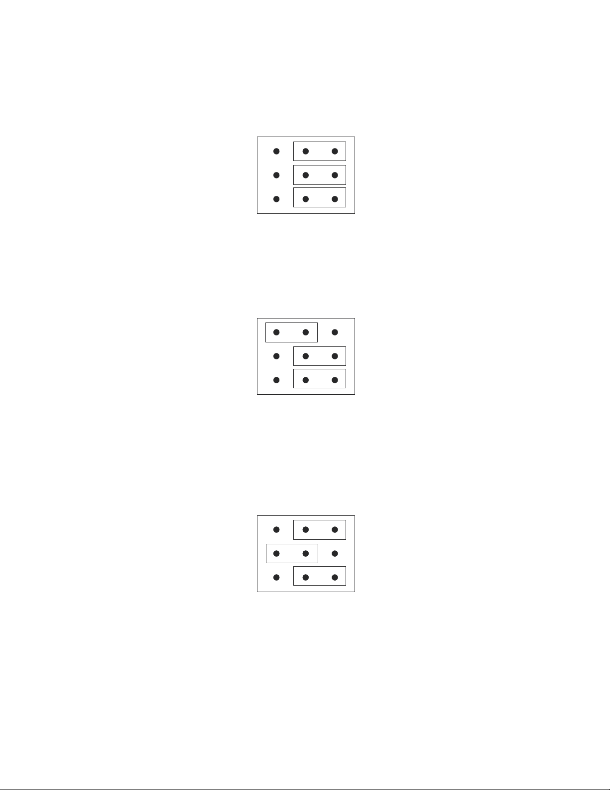
appropriate positions. Replace the acrylic panel when finished. See diagrams below.
To configure P10 for 150 bps, the shunts must be OFF OFF OFF:
P10
1
2
3
ON OFF
Shunt configuration for 150 bps
To configure P10 for 300 bps, the shunts must be ON OFF OFF:
P10
1
2
3
ON OFF
Shunt configuration for 300 bps
To configure P10 for 1200 bps, the shunts must be OFF ON OFF:
P10
1
2
3
ON OFF
Shunt configuration for 1200 bps
25
Page 26
Sensaphone® ISACC Instruction Manual
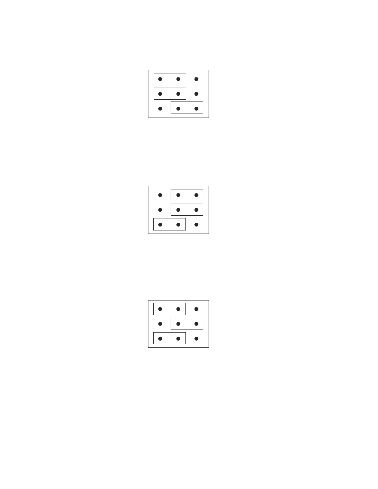
To configure P10 for 2400 bps, the shunts must be ON ON OFF:
P10
1
2
3
ON OFF
Shunt configuration for 2400 bps
To configure P10 for 4800 bps, the shunts must be OFF OFF ON:
P10
1
2
3
ON OFF
Shunt configuration for 4800 bps
To configure P10 for 9600 bps, the shunts must be ON OFF ON:
P10
1
2
3
ON OFF
Shunt configuration for 9600 bps
NOTE: Again, do not change the configuration of the shunts for local communication unless
you are positive that your PC cannot communicate at 9600 bps.
6. If you changed the position of the shunts, you must reset ISACC so that the unit can
recognize the new configuration. To do this press the reset button (a hole is provided in the
acrylic safety panel) or turn the ON-OFF switch off and back on again. If you did not
reconfigure the shunts, you do not need to reset ISACC.
26
Page 27

Chapter 3: Communication Setup
7. When using a PC to communicate locally with ISACC, you must next install communications software. Provided with ISACC is the ISACC MANAGER for Windows Software. The
package comes with four 3.5" floppy disks. Follow the instructions in the ISACC MANAGER User's Manual to install the software.
SETUP FOR TERMINAL
LOCAL COMMUNICATION THROUGH RS232 PORT
To communicate locally, you must hookup and configure ISACC’s RS232 port with your
terminal. ISACC’s RS232 port is positioned on the circuit board at location P4 next to the
phone jack and is labelled RS232 PORT (DCE). Provided with ISACC is an Accessory Bag
that contains the following:
• Male DB25 plug to RJ11C
• Female DB25 socket to RJ11C
• Female 9-pin socket
• 10 feet RS232 wire with male RJ11C on each end
To connect your terminal to ISACC’s RS232 port, do the following:
1. Insert the male DB25 plug into ISACC’s RS232 port
2. Insert one end of the RS232 wire into the male DB25 plug
3. Insert the other end of the RS232 wire into the female DB25 socket
4. Insert the female DB25 plug into your terminal’s male RS232 port.
NOTE: You may encounter a common problem at step four. Some terminals have a female
RS232 port. Since the provided equipment has a female DB25 socket, you may have to obtain
a gender changer to connect the socket to your terminal.
See page 30 for ISACC’s RS232 Specifications and a diagram of the RS232 DB25 socket.
5. After connecting the terminal with ISACC, you may need to configure your terminal's
RS232 port to communicate at the same speed (bps) as your terminal (refer to your terminal's
operator's manual). If this is not an option, you can change ISACC's communication rate by
configuring the shunts at location P10 on the ISACC board. Before changing anything, read
the following:
IMPORTANT: The speed of ISACC’s RS232 port is completely independent of
ISACC’s built-in modem or modem speed. ISACC’s modem has its own separate
RS232 port built in. Therefore, you do not need to configure ISACC to communicate at the same speed as its built-in modem (1200 bps) when you are communicating locally. Use the rate at which your terminal can communicate.
ISACC is factory configured at 9600 bps, which is the fastest it can communicate. Most
terminals can communicate at least that fast. Unless your terminal definitely communicates at
a slower speed, do not change the configuration of the shunts for local communication.
27
Page 28
Sensaphone® ISACC Instruction Manual
ISACC is capable of communicating locally at the following speeds:
150 bps 2400 bps
300 bps 4800 bps
1200 bps 9600 bps
There are 9 pins at location P10. (P10 is located under the acrylic safety panel next to the
digital outputs terminal block.) Three shunts are provided to configure the communication
speed for the RS232 port. The speed is determined by the different positions of the shunts.
All three shunts must be used for ISACC to communicate properly. To configure the shunts,
you must first remove the acrylic panel. Using needlenose pliers, move the shunts to the
appropriate positions. Replace the acrylic panel when finished. See diagrams below.
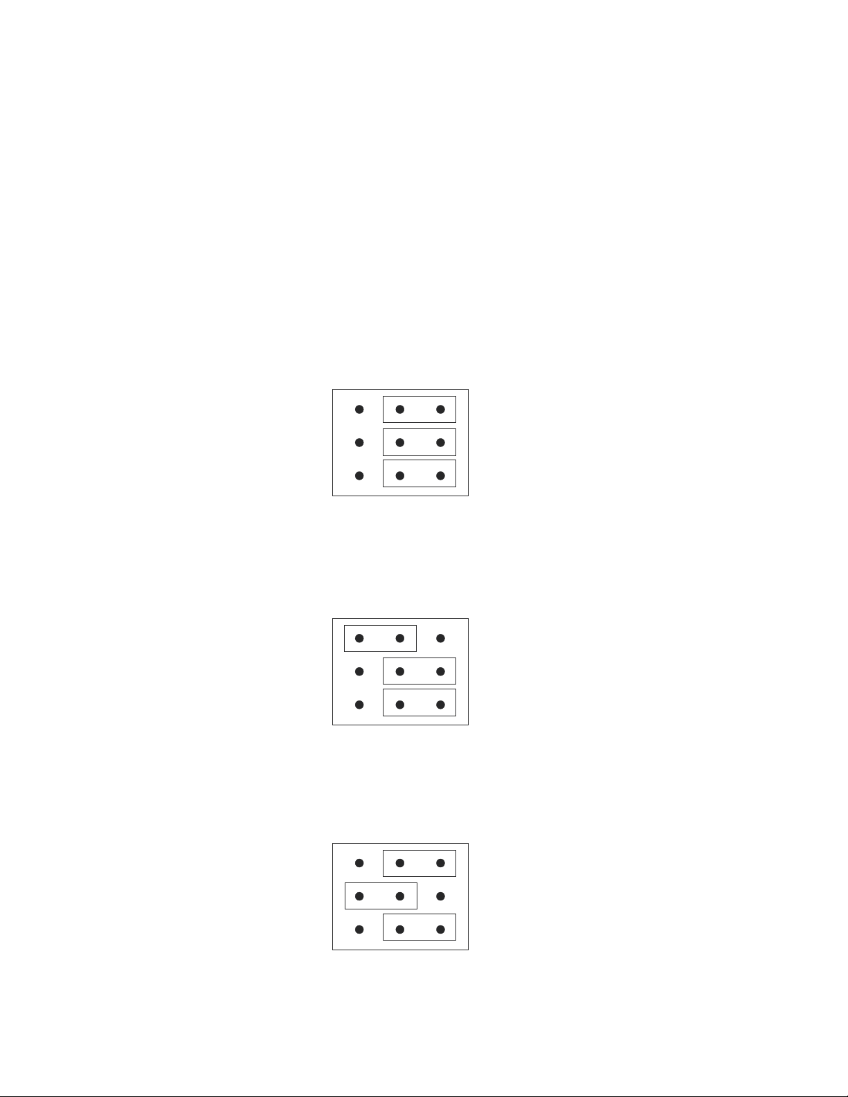
To configure P10 for 150 bps, the shunts must be OFF OFF OFF:
P10
1
2
3
ON OFF
Shunt configuration for 150 bps
To configure P10 for 300 bps, the shunts must be ON OFF OFF:
P10
1
2
3
ON OFF
Shunt configuration for 300 bps
To configure P10 for 1200 bps, the shunts must be OFF ON OFF:
P10
1
28
2
3
ON OFF
Shunt configuration for 1200 bps
Page 29
Chapter 3: Communication Setup
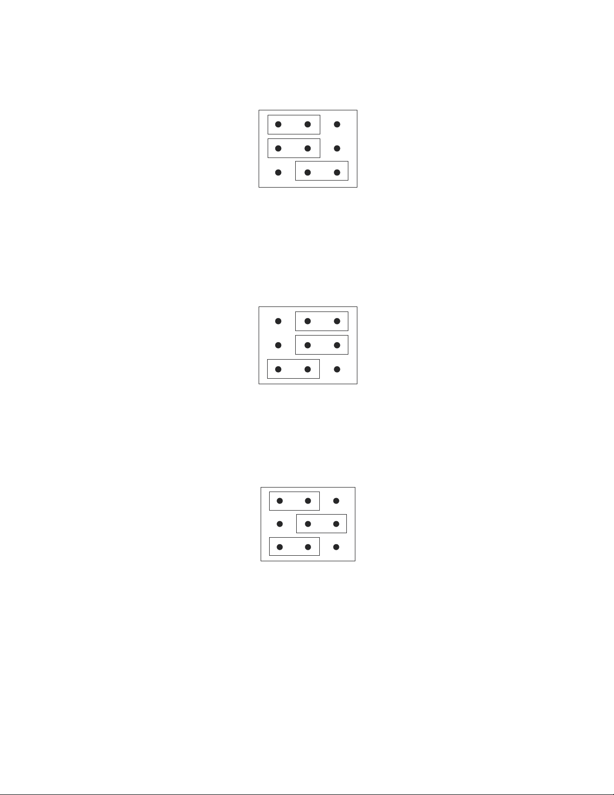
To configure P10 for 2400 bps, the shunts must be ON ON OFF:
P10
1
2
3
ON OFF
Shunt configuration for 2400 bps
To configure P10 for 4800 bps, the shunts must be OFF OFF ON:
P10
1
2
3
ON OFF
Shunt configuration for 4800 bps
To configure P10 for 9600 bps, the shunts must be ON OFF ON:
P10
1
2
3
ON OFF
Shunt configuration for 9600 bps
NOTE: Again, do not change the configuration of the shunts for local communications unless you are absolutely positive that your terminal cannot communicate at
9600 bps.
29
Page 30

Sensaphone® ISACC Instruction Manual
6. If you changed the position of the shunts, you must reset ISACC so the unit can recognize
the new configuration. To do this, press the reset button (a hole is provided in the acrylic
panel for easy access) or turn the ON-OFF switch off then on. If you did not reconfigure the
shunts, you do not need to reset ISACC.
7. Go to your terminal setup screen. Set the baud rate of the terminal to 9600 bps.
8. Press <RETURN>. You will receive the ISACC welcome screen. You are now online
with the unit and may begin programming and communication.
If you do not receive the ISACC welcome screen, there are only two possible problems. First,
the baud rates do not match. Double check that the terminal and ISACC are set to be the
same. If you are sure that they are correct, then you may need to add a null modem adaptor to
the terminal.
REMOTE COMMUNICATION VIA MODEM
To communicate with ISACC remotely, you must have a Hayes compatible modem installed
on your terminal. ISACC must be connected to an analog phone line (see Chapter 2: IN-
STALLATION: “Phone Line Installation”).
1. Go to your terminal setup screen. Next, you must set your terminal modem speed. The
calling modem (in this case, your terminal’s) establishes the baud rate of communication for
the receiving modem (ISACC). If the calling modem communicates at a faster speed than the
receiving modem can, there will be no communication. Therefore, set your terminal modem
rate to the fastest speed at which both the terminal modem and ISACC’s modem can commu-
nicate. For example:
If your terminal modem can communicate at 9600 bps, it can also communicate at 2400 bps,
1200 bps, and 300 bps. ISACC’s modem is a 1200 bps modem, it can communicate at 1200
bps and 300 bps. Set the terminal modem (calling modem) to call ISACC at 1200 bps because
this is the fastest that both can communicate. If you were to set the terminal baud rate to 300
bps, both will still communicate, but not at the optimum speed (not recommended).
NOTE: DO NOT RECONFIGURE THE SHUNTS AT LOCATION P10! ISACC’s
modem has a completely independent RS232 port that automatically configures
itself. The shunts at P10 are ONLY for local communication.
2. Type (in capital letters): ATZ
This will reset your terminal modem to recognize the new baud rate. You are now ready to
dial ISACC’s phone number.
3. Type (in capital letters): ATD followed by ISACC’s phone number. Or, if you want to dial
in touch-tones, type: ATDT followed by ISACC’s phone number. For example:
ATD5555674
ATDT5555674
4. Your modem will call ISACC. When it connects, you will receive the message CONNECT on your terminal screen, followed by the ISACC welcome screen. You are now online
and ready to begin programming and communication.
30
Page 31
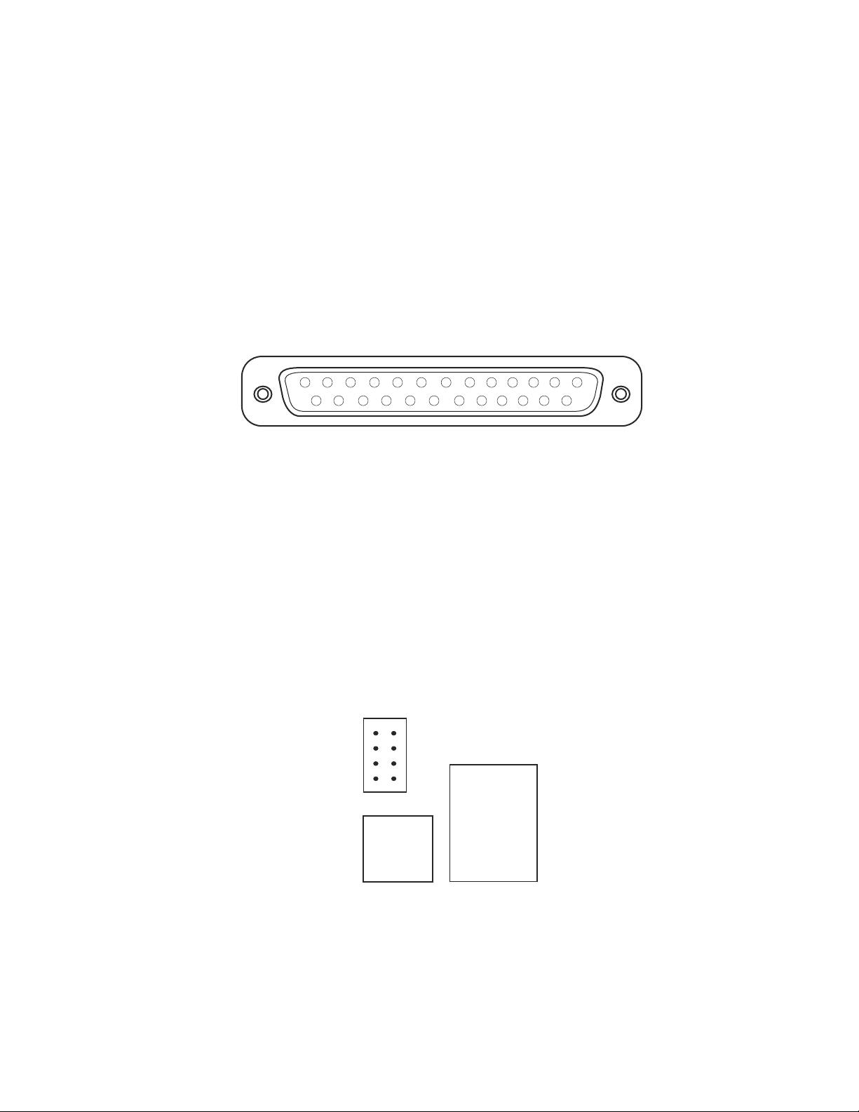
ISACC RS232 SPECIFICATIONS
Start/Stop protocol: XON/XOFF only
Communications protocol: 8 data bits, no parity, 1 stop bit
DB25 socket configuration: DCE female
RS232 receptacle configuration (refer to diagram below):
Pin 2 = Received Data (Receive)
Pin 3 = Transmitted Data (Send)
Pin 6 = DSR (Data Set Ready)
Pin 7 = Ground
13
12 11 10 9 8 7 6 23451
25 24 23 22 21 20 19 18 17 16 15 14
ISACC's RS232 DB25 Socket
Chapter 3: Communication Setup
NETWORK WIRING
ISACC units may be connected in a network using as few as two units and as many as 16
units. The units are connected together using 2 conductor twisted pair cable (Belden 9841 or
equivalent) to the networking terminal block (also called a port) labelled RS485. The 2position RS485 terminal block is positioned next to the RJ11 phone jack on the circuit board.
See below:
OFF
ON
P9
AB
RS485
RS485 networking port
PHONE
31
Page 32
Sensaphone® ISACC Instruction Manual
ISACC units are networked by connecting the A terminals together, and the B terminals
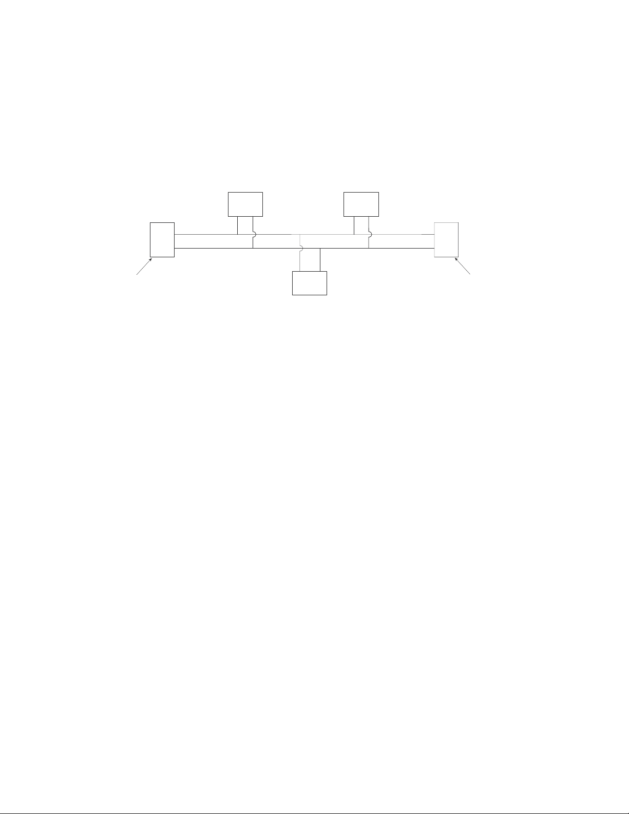
together. Next, it is necessary to enable a termination on the two units that are located farthest apart. This termination is located at pin header P9, located directly above the RS485
terminal block. To enable termination, move the two black jumpers from the off position to
the on position. If only two ISACC units are being networked, enable both. See the following diagram:
node 1 node 3
Termination
ON
node 0
A B A B
A
B
A B
node 2
Five ISACC units networked
node 4
A
B
Termination
ON
After the units are networked, you must determine the node number for each unit. This must
be done so that the each unit is identified in the network. The “master” unit is identified as 0
(zero). See Chapter 7: PROGRAMMING: “System”, for information on how to program the
network node number. See Chapter 7: PROGRAMMING: “Network” for information on how
to make a network request. See Chapter 8: C PROGRAMMING for information on how to
use network information in C programming.
32
Page 33
Chapter 4: Inputs
CHAPTER 4
○ ○ ○ ○ ○○○○○○○○○○○○○○○○○○○○○○○○○○○○○○○○○○○○○○○○○
INPUTS
ISACC comes with 16 user definable inputs that can sense the following: temperature, analog
voltage, analog current, dry contact and pulse count.
HOW THE INPUTS WORK
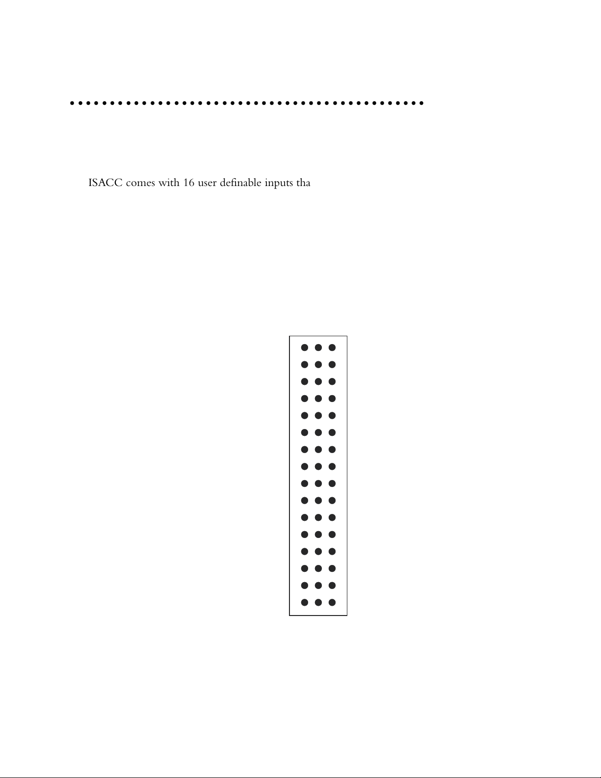
ISACC reads the value of each input by measuring the voltage across the input terminal and
common. ISACC can read the voltage between 0 Volts and 5 Volts, in increments of .00489
Volts. The inputs are configured by positioning the shunts at location P12 on the ISACC
circuit board. (P12 is located under the acrylic safety panel directly above the input terminal
block. Refer to Appendix B for a diagram of the ISACC board layout.) P12 has 16 sets of
pins, one set for each input. See diagram of P12 below:
P12
10
11
12
13
14
15
16
1
2
3
4
5
6
7
8
9
TEMP
4-20mA
The input configuration pins at P12
When the shunts are positioned for a specific type of sensor, ISACC uses a different circuit to
measure the appropriate reading for that sensor. The three configurations are single ended 420mA; thermistor/digital/pulse; and 0-5V. To configure an input channel, you must first
33
Page 34

®
Sensaphone
ISACC Instruction Manual
remove the acrylic panel. Using needlenose pliers, move the shunt to the appropriate position.
See diagrams below. Replace the acrylic panel when finished.
TEMP position - The default configuration connects the input signal to a 5V reference
through a 6.34K pull-up resistor. This configuration allows a thermistor, dry contact (N.C. or
N.O. ), or pulse counting sensor to be wired to the input. You may use either a 2.8K thermistor or a 10K thermistor with ISACC.
P12
1
TEMP
4-20mA
Thermistor, dry contact or pulse count configuration
4-20mA position - This configuration connects the input signal to a 249 Ohm load resistor.
This allows ISACC to measure the current at the input. Any sensor that puts out 4-20mA can
be wired to this input.
P12
1
TEMP
4-20mA
4-20mA configuration
0-5V (NO SHUNT) position - This configuration connects the input signal directly to
ISACC’s analog to digital converter for measuring the output of 0 to 5 volt transducers. Any
sensor that puts out 0-5V can be wired to this input.
P12
1
TEMP
4-20mA
0-5 Volt configuration
CAUTION: Wiring sensors with shunts in the incorrect position could result in
damage to the unit.
34
Page 35
Chapter 4: Inputs
INPUT TERMINAL BLOCK
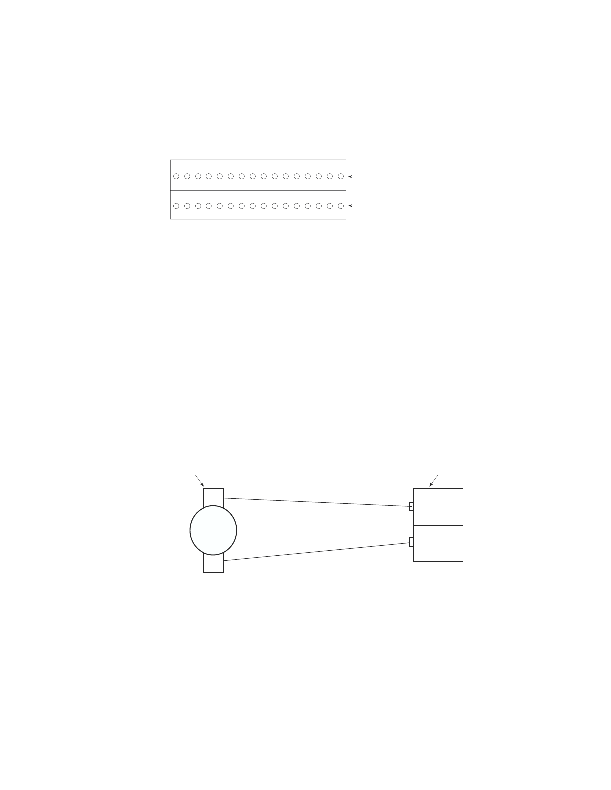
On the circuit board, each input terminal is located on the double row terminal block labeled
INPUTS. The bottom row is the positive input terminal and the top row is the common
terminal. All commons are the same and are internally connected. See diagram below:
INPUTS
Commons
Input terminal screws
1 2 3 4 5 6 7 8 9 10 11 12 13 14 15 16
Input terminal block
NOTE: If you are using the ABS plastic enclosure, you must remove the top cover to
access the circuit board. After wiring is completed, reinstall the top cover. All wiring
should be properly fitted through the strain relief clamps. Strain relief is provided in
the ISACC enclosure to prevent wiring from being pulled from the circuit board or
damaged while passing through the enclosure. To use, thread wires through the clamp
and clear rubber bushing. Position the bushing in the clamp and tighten the screws on
either side so that the wiring does not move.
WIRING SENSORS TO THE INPUTS
Dry contact/Thermistor/Pulse count - To use a dry contact sensor, thermistor, or pulse
counter on an input, wire one lead to the numbered screw of an input terminal and the other
lead to the corresponding common screw. See diagram below:
Dry contact sensor
NO / NC
Dry contact/ Thermistor/Pulse count sensor
Input terminal pair
COMMON
INPUT
4-20mA (internally powered) - To use a 4-20mA sensor on an input, you must supply
power to it. You may power a 4-20mA sensor using ISACC's internal power supply, or you
may wire the sensor to an external power supply. NOTE: The number of internally powered
sensors will affect battery backup time during a power failure. To use the internal power
supply, wire the positive lead from the sensor to ISACC's 15V power supply (located on the
POWER terminal block). Wire the negative lead to a numbered input terminal screw. See
following diagram:
35
Page 36
Sensaphone
®
ISACC Instruction Manual
4-20mA sensor
+
POWER
EG 24 24 BAT C 20V C 15V C 12V C 5V C
AC AC
Wire to the 15V power supply.
Power supply
terminal block
4-20MA
-
COMMON
INPUT
Input terminal pair
4-20mA sensor using internal power supply
4-20mA (externally powered) - To use an external power supply, wire the positive lead
from the sensor to the positive terminal on the external power source. Wire the negative lead
from the sensor to a numbered input screw on ISACC. Next, connect the power supply to
ISACC by wiring the negative terminal on the power supply to a common screw on ISACC.
See diagram below:
External power source
COMMON
VDC
4-20mA sensor
+ 4-20mA-
INPUT
Input terminal pair
4-20mA sensor using external power source
0-5V sensor - To use a 0-5V sensor with ISACC, wire the sensor signal lead to a numbered
input terminal screw on the unit. Then, wire the sensor common to the corresponding common screw on ISACC. See diagram below:
Common
COMMON
0-5V
INPUT
Signal
Input terminal pair
0-5V sensor
SHIELDED WIRE
ISACC is designed to work in most installations without the need of shielded wire. This does
not apply to wire run in conduit that has other noise-generating conductors such as 60Hz AC.
36
Page 37

Chapter 4: Inputs
It is strongly recommended that input wiring be run in a conduit separated from AC power or
output wiring. When wire runs are long or are in close proximity to large power consuming,
power generating or power switching equipment, it is recommended that SHIELDED WIRE
be used. Not doing so may cause erroneous input readings.
LENGTH OF WIRE
Temperature - It is recommended that long wire runs be avoided when using a thermistor
as a sensor. A long run of wire could alter the resistance of the circuit therefore providing an
inaccurate temperature reading of the input. Below is a chart of recommended gauges and
wire lengths:
MINIMUM WIRE GAUGE MAXIMUM WIRE LENGTH LOOP RESISTANCE
#26 250 feet 10.2 Ohms
#24 700 feet 18 Ohms
#22 1500 feet 24.15 Ohms
#20 2500 feet 25.5 Ohms
Dry contact - The total resistance of the loop cannot exceed 50 Ohms. Use the table above
to determine the appropriate GAUGE wire for your application.
Analog Current - Long wire runs will not affect the accuracy of the input because there is
constant current being driven through the sensor wire.
Analog Voltage - Wire runs should be kept as short as possible to avoid voltage drops and
noise susceptibility. Use the chart above as a guideline.
NOTE: All wiring should comply with section 17 of the UL requirements.
INPUT MODULES
Solid state input modules may also be used with ISACC. Input modules provide a reliable
means of interfacing between ISACC and an outside device. Input modules come in AC and
DC versions and are used to measure the presence or absence of AC or DC voltage, respectively.
The ISACC enclosure comes predrilled to mount a 4-module rack using four #6-32 1"
machine screws. If you are using input modules, you must hardwire the rack to ISACC. If
your application requires the use of many input modules, you may want to consider using a
16-module rack. See end of this section.
NOTE: With the 4-module racks, you may use a combination of input and output
modules in the same rack. For information on output modules, See Chapter 5:
Outputs.
To use the 4-module rack with ISACC:
1. Insert solid state modules into the 4-module rack.
2. Place the rack in front of you so that 2IO-4A is at the top and the LEDs are on
your right.
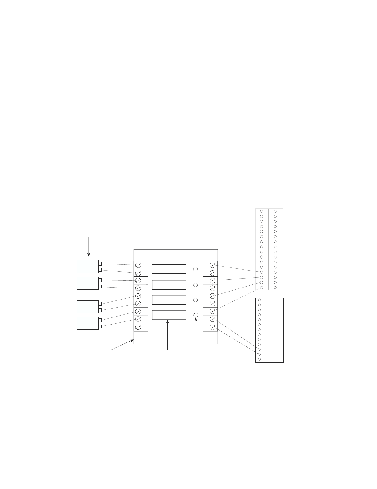
3. The right side of the 4-module rack is the logic I/O that is wired to ISACC. The
left side of the board is the field I/O that is wired to the I/O devices.
37
Page 38
®
Sensaphone
ISACC Instruction Manual
To wire the logic I/O (right side) to ISACC:
1. Attach terminal 1 (on the right side) to 5 VDC on the ISACC power supply terminal block. Attach terminal 2 to one of the C (common) terminals on the ISACC
power supply terminal block.
2. Connect an odd-numbered terminal (3, 5, 7, or 9) to one of the ISACC input
terminals (1-16) on the bottom row terminal block. The shunt for this input must be
in the TEMP position.
To wire the field I/O (left side) to the input device:
If the input device is DC:
1. Connect ground from the outside device to the odd-numbered terminal (3, 5, 7, or
9) on the rack.
2. Connect the positive voltage from the outside device to the even-numbered termi-
nal (2, 4, 6, or 8) on the rack.
If the input device is AC, polarity does not matter and either wire can be connected to a
terminal pair on the rack.
See sample diagram below:
Input devices
DC device
DC device
AC device
AC device
G
+
G
+
4-module rack
2I0-4A
9
DC input
8
7
DC input
6
5
AC input
4
3
AC input
2
1
Wiring AC and DC input modules using a 4-module rack
9
8
7
6
5
4
3
2
1
LEDSolid state modules
1 2 3 4 5 6 7 8 9 10 11 12 13 14 15 16
EG 24 24 BAT C 20V C 15V C 12V C 5V C
AC AC
INPUTS
POWER
DIP CONNECTOR FOR A 16-MODULE RACK
If you need to use all 16 inputs for monitoring AC or DC voltage, you may simplify your
wiring by using a 16-module rack (Potter & Brumfield 2IO16), with a 50-pin ribbon cable
with a card edge connector on one end and a 50-pin socket connector on the other end. The
socket connector connects to the ISACC unit and the card edge connector connects to the
38
Page 39
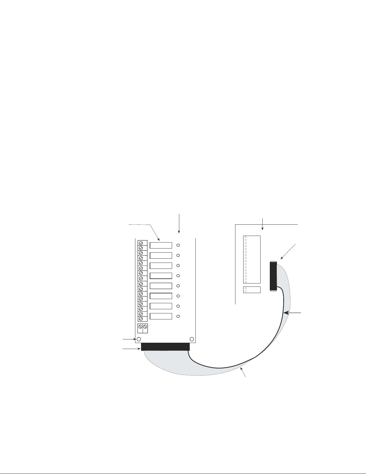
Chapter 4: Inputs
16-module rack. On the ISACC circuit board is a 50-pin DIP connector at
location P13 (located adjacent to the input terminal block). The signals at the DIP
header are internally connected to the input terminal block. Configure all input
shunts to the TEMP position.
IMPORTANT: The 16-module rack is used in lieu of the input terminal
block, both cannot be used at the same time. When using a 16-module
I/O rack, all 16 inputs are dedicated to using input modules. If a smaller
number of input modules are needed, use a smaller rack and hardwire
the rack to the input block.
To use the 16-module rack:
1. Connect the ribbon cable between the 16-module rack and the DIP
connector on ISACC. Make sure that pin 1 on the rack connects to pin 1
on the DIP header.
2. Install the jumper wire at the card edge pad 49 on the rack, or connect
the positive terminal on the rack's 2-position terminal strip to 5V on the
ISACC POWER terminal block.
16-module
Solid state
output modules
16 15 14 13 12 11 10 8976543
2
1
DC input
DC input
DC input
DC input
AC input
AC input
AC input
AC input
rack
2IO-16
0 1 2 3 4 5 6 7
(Input terminal
cannot be used
with the 16-
module rack)
ISACC circuit board
1 2 3 4 5 6 7 8 9 10 11 12
INPUTS
13 14 15 16
P13
Socket connector
plugged into P13
on ISACC circuit
board
1
Red stripe
Mounting hole
Card edge connector
- +
49
1
Ribbon cable
16-module rack connection
39
Page 40

®
Sensaphone
ISACC Instruction Manual
ISACC INPUT SPECIFICATIONS
Voltage Range: 0 to +5 VDC
Minimum/Maximum Input Voltage: -0.5VDC to +5.5VDC
Input Resolution: 10 Bit or 0.004888V
A/D Converter Typical Total Unadjusted Error: ± 1 LSB
Accuracy (TEMP POSITION): ± 1° F typical using Phonetics 2.8K
temperature sensor
Accuracy (4-20mA POSITION): ± 1.25%
Maximum Pulse Frequency: 1.0Hz
Minumum Pulse Width: 400ms
Noise Filtering: 2300Hz low pass filter
-20dB/Decade
INPUT MODULE SPECIFICATIONS
AC INPUT MODULE (FGD-0018):
Input Voltage: 90 - 140 VAC/VDC
Input Current: 8 - 12 mA
Output Current: 100 mA DC max.
Output Leakage: 100 µA DC max.
Logic Supply Voltage: 5 VDC
Logic Supply Current: 10 mA DC typical
DC INPUT MODULE (FGD-0017):
Input Voltage: 3-32 VDC
Input Current: 10-15 mA
Output Current: 100 mA DC
Output Leakage: 100 µA DC
Logic Supply: 5 VDC
Logic Supply Current: 10 mA DC
40
Page 41
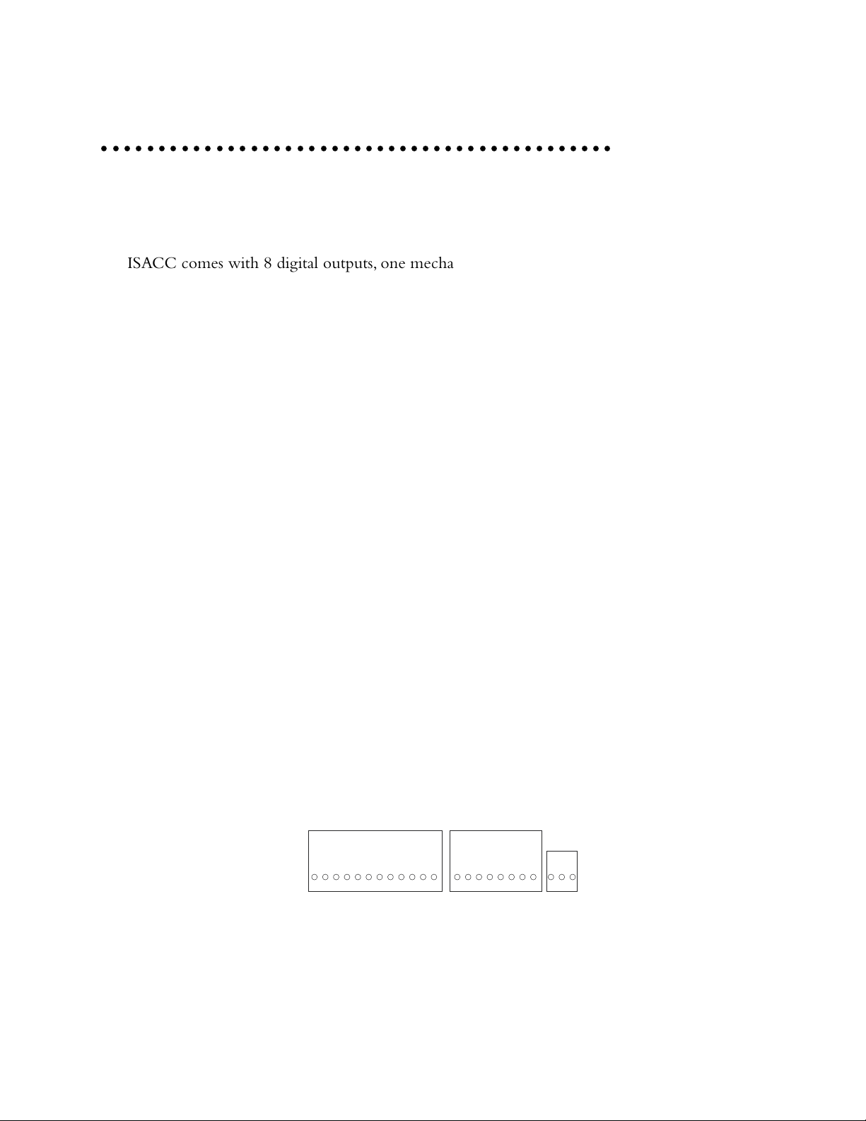
Chapter 5: Outputs
CHAPTER 5
○○○○○○○○○○○○○○○○○○○○○○○○○○○○○○○○○○○○○○○○○○○○○
OUTPUTS
ISACC comes with 8 digital outputs, one mechanical relay, one on-board buzzer, and four
analog outputs.
NOTE: All wiring should comply with section 17 of the UL requirements.
HOW THE OUTPUTS WORK
On-board buzzer - is considered an output that acts as a local audible indicator. Its function is controlled by programming. No wiring required. It is referred to as output 9 in the
programming parameters. It may be controlled manually, or automatically by C program.
Mechanical SPDT Relay - used for simple on/off switching of up to 5 Amps. If your
application requires the use of only one output, the on-board relay may be appropriate. It is
referred to as output 10 in the programming parameters. It may be controlled manually, or
automatically by C program.
Digital Outputs - used to control equipment such as heating, air conditioning, ventilation,
lighting, power, etc. The outputs are low level 5 volt TTL signals capable of sinking or sourcing about 20mA. The logical operation of the outputs is OFF = 5 volts and ON = 0 volts.
The digital outputs require an interface such as solid state relays to be used. The digital outputs are referred to as outputs 1-8 in the programming parameters. They may be controlled
manually, or automatically by C program.
Analog Outputs - provide proportional control of equipment and do not require an interface
to be used. The analog outputs are 0 to 10 Volts, specified by a number from 0 to 255. They
are controlled automatically by C program and are referred to as outputs 11 through 14 in the
programming parameters. They may be controlled manually, or automatically by C program.
OUTPUT TERMINAL BLOCKS
On the circuit board, the outputs are available on three different terminal blocks labelled
DIGITAL OUTPUTS, ANALOG OUTPUTS, and RELAY. See diagram below:
DIGITAL OUTPUTS
8 7 6 5 4 3 2 1 C 12V C 5V
Output terminal blocks
NOTE: If you are using the ABS plastic enclosure, you must remove the top cover to access
the circuit board. After wiring is completed, reinstall the top cover. All wiring should be
properly fitted through the strain relief clamps. Strain relief is provided in the ISACC
enclosure to prevent wiring from being pulled from the circuit board or damaged while
ANALOG OUTPUTS
C 4 C 3 C 2 C 1
RELAY
NC COM NO
41
Page 42

Sensaphone® ISACC Instruction Manual
passing through the enclosure. To use, thread wires through the clamp and clear rubber
bushing. Position the bushing in the clamp and tighten the screws on either side so that
the wiring does not move.
WIRING THE MECHANICAL RELAY
To wire a device to the mechanical relay using an ISACC power supply:
1. Wire one lead from the device to the terminal marked NO on the relay terminal
block.
2. Wire the other lead from the device to a common on ISACC's POWER supply
terminal block.
3. Wire the terminal marked COM on the relay terminal block to a power terminal
(5V, 12V, 15V, or 20V) on ISACC's POWER supply terminal block.
NOTE: If the unit powers off, the relay will revert to "normal" condition. It is not Latching!
See diagram below:
POWER
RELAY
EG 24 24 BAT C 20V C 15V C 12V C 5V C
AC AC
NC COM NO
- +
Outside device
Wiring a device to mechanical relay using an ISACC power supply
To wire a device to the mechanical relay using an external power source:
1. Wire one lead from the device to the terminal marked NO on the relay terminal
block.
2. Wire the other lead from the device to the NEUTRAL terminal on the external
power source.
3. Wire the terminal marked COM on the relay terminal block to the HOT terminal
on the external power supply.
See diagram next page.
42
Page 43
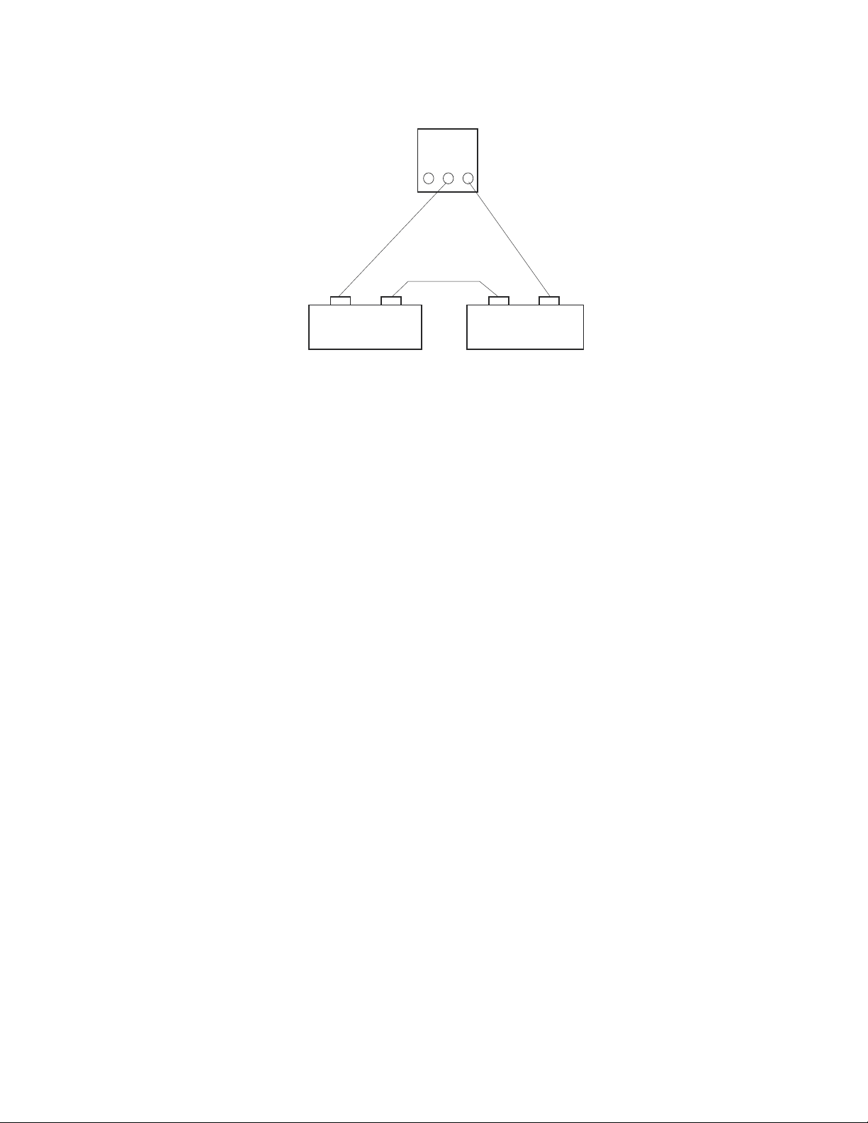
Chapter 5: Outputs
RELAY
NC COM NO
HOT NEUTRAL
External
power source
Wiring a device to mechanical relay using an external power source
NOTE: The NO/NC status is only valid while the unit is on. Should the unit lose power,
the relay will invert position.
Outside device
WIRING THE DIGITAL OUTPUTS
In order to use the digital outputs to control other equipment, an appropriate interface is
required. Optically isolated solid state relays provide the optimum interface to be driven by
the digital outputs. These are preferred because they isolate ISACC from the equipment being
switched. The two types that can be used with ISACC are:
• Solid state output modules
• High power solid state relays (FGD-0020)
If the equipment that needs to be switched requires less than 3 Amps, use solid state output
modules mounted in a 4- or 8-module rack. If the equipment requires more than 3 Amps,
individual high power solid state relays must be used.
Solid State Output Modules - The solid state output modules come in AC and DC versions and are typically limited to 3 Amp switching. They are designed to be plugged into
output mounting boards (racks). The ISACC enclosure is predrilled to mount either one 4module rack or one 8-module rack using four #6-32 1" machine screws. See Appendix C for
mounting diagrams.
AC and DC output modules (FGD-0015 and FGD-0016), the 4-module rack (FGD-0021),
and the 8-module rack (FGD-0039) are available from Phonetics. See Appendix D for accessory information. Other output modules from different manufactures may be used with
ISACC. Contact Phonetics for more information.
If you use an 8-module rack, you must use a ribbon cable to connect AC/DC output modules
to ISACC. The ribbon cable attaches to the rack and plugs into a 26-pin DIP header at
location P14 on ISACC. The output signals at the DIP header are internally connected to
those at the terminal block. This is only for the digital outputs, there is no DIP connector for
the analog outputs. See the 8-module rack installation diagram.
NOTE: With the 4-module rack, you may use a combination of input and output modules.
For more information on using and wiring input modules, see Chapter 4: Inputs.
43
Page 44

Sensaphone® ISACC Instruction Manual
To wire the 4-module rack logic I/O to ISACC:
1. Insert solid state modules into the 4-module rack.
2. Mount the rack in the ISACC enclosure so that it is parallel to the
ISACC circuit board, with the LED side closest to the circuit board. The
LED side is called the logic I/O and is wired to ISACC. The other side is
called the field I/O and is wired to the AC and DC devices.
3. Wire terminal 1 on the rack to 5 VDC on the ISACC digital output
terminal block. Attach terminal 2 to one of the C (common) terminals on
the ISACC digital output terminal block.
4. Connect an odd-numbered terminal (3, 5, 7, or 9) on the rack to a
digital output terminal (1-8) on ISACC.
To wire the 4-module rack field I/O to DC devices using an ISACC power supply:
1. Connect ground from the DC device to a common on ISACC's power
supply terminal block.
2. Connect an even-numbered terminal on the 4-module rack to a power
terminal (20V, 15V, 12V, or 5V) on ISACC's power supply terminal block.
3. Connect the positive terminal from the DC device to the odd-num-
bered terminal (2, 4, 6, or 8) on the rack.
4. If you use more than one DC module, you may wire the even-num-
bered terminals on the rack together (if they require the same voltage) to
supply power, and the ground terminals on the DC devices together to
ground.
To wire the 4-module rack field I/O to AC devices using an external power supply:
1. Wire the HOT terminal from the external power supply to an odd-
numbered terminal on the 4-module rack.
2. Wire the NEUTRAL terminal from the external power supply to a
terminal on the AC device.
3. Wire the other terminal on the AC device to an even-numbered termi-
nal on the 4-module rack.
4. When using more than one AC module, you may wire the odd num-
bered-terminals on the rack together, and the neutral terminals on the AC
devices together.
See diagram on next page.
NOTE: If you are using the ABS plastic enclosure, any external wiring must go
through the strain relief clamps in the wall of the enclosure. Replace the top
cover after installation. Terminal 1 on the field I/O side of the 4-module rack is
unused.
44
Page 45
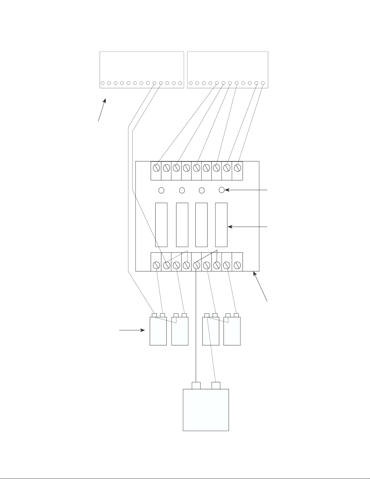
Chapter 5: Outputs
9
8
7
6
5
4
3
2
1
9
8
7
6
5
4
3
2
1
DC output
DC output
2I0-4A
LED
Solid state modules
AC output
AC output
DIGITAL OUTPUTS
8 7 6 5 4 3 2 1 C 12V C 5V
DC device
+
G
DC device
+
G
AC device
AC device
AC external
power supply
HOTNEUTRAL
Output devices
Power supply and digital
outputs terminal blocks
on ISACC circuit board
POWER
EG 24 24 BAT C 20V C 15V C
12V C 5V C
AC AC
4-module rack
Using 4-module rack with ISACC
45
Page 46
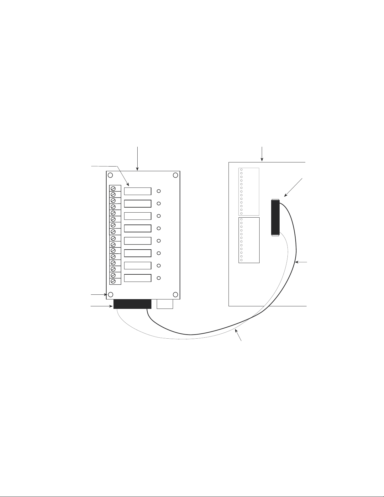
Sensaphone® ISACC Instruction Manual
To install the 8-module rack with ISACC:
1. Insert the solid state modules into the 8-module rack.
2. Mount the rack in the ISACC enclosure so that it is parallel to the ISACC circuit
board, with the LED side closest to the circuit board.
3. Plug the ribbon cable card edge connector to the rack with the red stripe at pin 1.
4. Insert the socket connector into the 26-pin DIP header at location P14 on the
ISACC circuit board with the red stripe at pin 1.
See diagram below:
ISACC circuit board8-module rack
Solid state
output modules
Mounting hole
Card edge connector
EG 24 24 BAT C 20V C 15V C 12V C 5V C
AC AC
Socket connector
16 15 14 13 12 11 10 9 8 7 6 5 4 3 2 1
DC output
DC output
DC output
DC output
AC output
AC output
AC output
AC output
25
1
2IO-8
8 7 6 5 4 3 2 1 C 12V C 5V
0 1 2 3 4 5 6 7
POWER
P14
1
DIGITAL OUTPUTS
plugged into P14
on ISACC circuit
board
Red stripe
Ribbon cable
Installing the 8-module rack with ISACC
To wire a DC device to the 8-module rack using an ISACC power supply:
1. Wire the ground terminal on the DC device to a common on the ISACC POWER
supply terminal block.
2. Wire the positive terminal on the DC device to an even-numbered terminal on the
8-module rack.
3. Wire an odd-numbered terminal on the 8-module rack to a power terminal (5V,
12V, 15V, or 20V depending on your application) on the ISACC POWER supply
terminal block.
46
Page 47
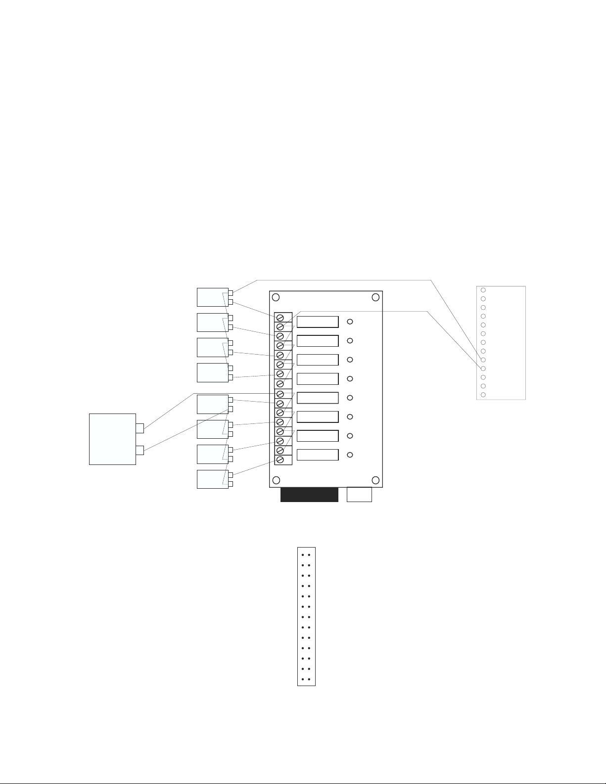
4. When using more than one DC device, you may wire all the device ground terminals together, and wire the odd-numbered terminals on the 8-module rack together if
all the DC devices require the same voltage.
To wire an AC device to the 8-module rack using external AC power source:
1. Wire the HOT terminal on the external AC power source to an even-numbered
terminal on the 8-module rack.
2. Wire the NEUTRAL terminal on the external power source to one of the AC
device terminals.
3. Wire the other AC device terminal to an odd-numbered terminal on the 8-module
rack.
4. When using more than one AC device, you may wire the even-numbered terminals
on the rack together, and wire the neutral terminals on the AC devices together.
See diagram below:
G
DC device
DC device
DC device
DC device
+
G
+
G
+
G
+
16 15 14 13 12 11 10 9 8 7 6 5 4 3 2 1
DC output
DC output
DC output
DC output
2IO-8
Chapter 5: Outputs
EG 24 24 BAT C 20V C 15V C 12V C 5V C
AC AC
POWER
AC output
AC output
AC output
AC output
25
1
AC external
power supply
HOTNEUTRAL
AC device
AC device
AC device
AC device
Wiring the AC and DC devices to the 8-module rack
Below is a pin-out of the digital outputs DIP connector:
Common 26
Common 24
Common 22
Common 20
Common 18
Common 16
Common 14
Common 12
Common 10
Common 8
Common 6
Common 4
Common 2
26-pin DIP header at P14
25 +5V
23 Output 1
21 Output 2
19 Output 3
17 Output 4
15 Output 5
13 Output 6
11 Output 7
9 Output 8
7 N.C.
5 N.C.
3 N.C.
1 +12V
P14
0 1 2 3 4 5 6 7
47
Page 48

Sensaphone® ISACC Instruction Manual
High Power Solid State Relay - The 25 Amp high power solid state relay (FGD-0020) is
available from Phonetics. See Appendix D for accessory information. The ISACC enclosure is
predrilled to mount as many as 8 high power solid state relays using two #6-32 ˘” machine
screws. See Appendix C for mounting diagrams.
NOTE: Do not use a high power solid state relay when a lower power relay will be sufficient. Solid state relays require a certain minimum current to switch (see page 54 for solid
state relay specifications). If a lower power relay is sufficient to switch the required current, but you have a high power relay wired, the output may not switch. Likewise, a
certain amount of leakage current also occurs. With a high power relay, this could be
sufficient to cause unintended switching of an output.
To use a high power solid state relay:
1. Mount the relay in the ISACC enclosure so that terminals 3 and 4 are closest to the
ISACC circuit board.
2. Wire terminal 3 on the relay to the 5V terminal on the DIGITAL OUTPUTS
terminal block.
3. Wire terminal 4 on the relay to one of the digital output terminals (1-8).
4. Wire terminal 2 on the relay to one of the terminals on the AC device.
5. Wire the other terminal on the AC device to the NEUTRAL terminal on the AC
external power source.
6. Wire the HOT terminal on the AC external power source to terminal 1 on the
relay.
See diagram below:
CAUTION: Exercise care when handling high voltage, high current circuits. Failure to do
so may result in electrical shock, fire, and/or serious bodily harm.
AC power source
HOT NEUTRAL
8 7 6 5 4 3 2 1 C 12V C 5V
1 2
High power solid
state relay
- +
4 3
DIGITAL OUTPUTS
AC device
48
Wiring a high power solid state relay
Page 49

WIRING THE ANALOG OUTPUTS
To wire the analog outputs:
1. Wire the positive terminal on the DC device to a numbered terminal on the analog
outputs terminal block.
2. Wire the negative terminal on the DC device to a common on the analog outputs
terminal block.
See diagram below:
ANALOG OUTPUTS
C 4 C 3 C 2 C 1
Chapter 5: Outputs
- +
DC device
Wiring an analog device
OUTPUT SPECIFICATIONS
DIGITAL:
Output Voltage 0 to 5V
Output Source Current (V = 0V) -30mA Max
Output Sink Current (V = 5V) 20mA Max
ANALOG:
Output Voltage 0 to 10V
Resolution 8 bits or .03137V
Maximum Total Unadjusted Error +2 LSB
Voltage Output Slew Rate 3V/µs
Voltage Output Settling Time 4µs
Minimum Output Load Resistance (V = 10V) 2K
RELAY:
Type: SPDT
Rated Load 5A at 120VAC
5A at 30VDC
Carry Current 5A
49
Page 50

Sensaphone® ISACC Instruction Manual
Maximum Operating Voltage 250VAC
125VDC
Maximum Operating Current 5A (AC/DC)
Maximum Switching Capacity 1,250VA, 150W
BUZZER:
Sound Output 80dB at 30cm
Frequency 400Hz +50Hz
SOLID STATE RELAY SPECIFICATIONS
AC Output Module (FGD-0015):
Voltage range: 24 - 140 Vrms
Max current: 3 Arms
Min current: 20 mArms
Typical leakage current: 2 mArms at 120 Vrms
DC Output Module (FGD-0016):
Voltage range: 5 - 60 V DC
Max current: 3 A DC
Min current: 20 mA DC
Typical leakage: .5 mA at 32 V DC
High Power Solid State Relay (FGD-0020):
Voltage range: 24 - 140 Vrms
Max current: 25 Arms
Min current: 50 mArms
Typical leakage: 7.5 mArms at 140 Vrms
50
Page 51

Chapter 6: Power Supplies
CHAPTER 6
○○○○○○○○○○○○○○○○○○○○○○○○○○○○○○○○○○○○○○○○○○○○○
POWER SUPPLIES
ISACC has four power supplies available from the PC board. They are there to power your
external sensors, solid state relays or output devices. Below are the specifications for these
power supplies:
Maximum Available Current
5V Supply 200mA
12V Supply 200mA
15V Supply 100mA
20V Supply 100mA
POWER
EG 24 24 BAT C 20V C 5 V C 12V C 5V C
AC AC
Power supply terminal block
The 5 Volt, 12 Volt, 15 Volt, and 20 Volt supplies are battery backed, but usage affects battery
backup time. The charge voltage at the BAT terminal is 20.4 Volts. Main power (24VAC) is
supplied through the two terminals labelled 24 and 24. The Earth Ground Terminal is labelled
EG.
NOTE: If you are using the ABS plastic enclosure, you must remove the top cover to access
the circuit board. After wiring is completed, reinstall the top cover. All wiring should be
properly fitted through the strain relief clamps. Strain relief is provided in the ISACC
enclosure to prevent wiring from being pulled from the circuit board or damaged while
passing through the enclosure. To use, thread wires through the clamp and clear rubber
bushing. Position the bushing in the clamp and tighten the screws on either side so that
the wiring does not move.
All wiring should comply with section 17 of the UL requirements.
51
Page 52

Sensaphone® ISACC Instruction Manual
52
Page 53

Chapter 7: Programming
CHAPTER 7
○○○○○○○○○○○○○○○○○○○○○○○○○○○○○○○○○○○○○○○○○○○○○
PROGRAMMING
The standard parameter programming and system setup of ISACC is accomplished through
using short command words called KEYWORDS and STAND ALONE commands. To use
either type of command, you simply type the letters after an ISACC prompt (ISACC>) and
then press the ENTER (or RETURN) key.
Note About Programming Examples: Commands and example information in this chapter
that are typed in by the user are represented in bold type. This is so that you can easily see
what has been changed.
KEYWORDS
There are two main components of a keyword command: the command prefix words SET or
SHOW followed by the KEYWORD. SET allows you to make a change in a parameter.
SHOW lists the current values of the parameter. The KEYWORDS represent all the system
and programming parameters. They are:
SYSTEM RECOGNITION SELECTION
CLOCK ALARMS VOICE
INPUTS DIALOUT LOGGING
ITYPE OUTPUTS NETWORK
TABLE ONAME VARIABLES
LIMITS PHONE
The format for using a keyword command is the following:
ISACC>SET (KEYWORD)
ISACC>SHOW (KEYWORD)
You may abbreviate the prefix and the keyword by using only the first three letters of each
word. For example, the command “show system” may also be typed as “sho sys”. The
command “set system” may be typed as “set sys”. This applies for all the keyword com-
mands.
You may specify which item you want to program or interrogate for certain input, output and
phone parameters. To do this, type set or show followed by the keyword and the number of
the input, output or phone. For example, to show the programming for phone number 3,
type:
ISACC>show phone 3
DIALOUT PHONE NUMBER, DIALING MODE, AND LABEL NAME
PH03, Num =
Dialing mode = (Voice ) > Name = "Phone #3 "
53
Page 54

®
Sensaphone
SYSTEM
ISACC Instruction Manual
This keyword allows you access to the global system parameters, including:
Unit identification - You may assign a name to the ISACC unit for identification. The name
may be up to 31 numbers or characters long.
Phone number of unit - The ISACC unit may be reached at this number. This number is
used in voice mode identification. The phone number may be up to 31 digits long and can be
typed plain, using hyphens and parentheses. Example:
Phone number of unit = >16105551234
Phone number of unit = >1-610-555-1234
Phone number of unit = >1(610)555-1234
Data password - The data password can be any combination of numbers or letters up to 30
characters long. The password is case sensitive. You MUST enter the password exactly as it
was originally programmed, with capitals, small letters, punctuation, etc. If the password is
forgotten, the only way to access ISACC is to turn the unit off and remove the lithium battery.
All programming will be deleted and reset back to the default settings.
Network node number - Up to 16 ISACC units may be networked together in series via
the RS485 port. The network node number identifies the ISACC unit in the network. This
number may be from 0 to 15, the default is 1. If ISACC is not part of a network, its network
node number should be set to 1.
Rings until answer - This parameter is the number of rings ISACC will wait before answering the phone line when the unit is being called. The rings may be programmed from 1 to 15,
the default is 1.
Phone dialing - This parameter allows you to determine whether ISACC will dial out using
pulse or tone dialing. The unit will prompt you to enter 0 for pulse or 1 for tone, the default
is tone.
Time between calls - This parameter is the length of time that ISACC will wait between
phone calls before dialing the next phone number on the list. The time between calls may be
programmed from 5 seconds to 270 minutes, the default is 30 seconds.
Wait time between rounds - This parameter allows you to program the time ISACC will
wait before it resumes calling from the top of the phone list after it finishes a round. The wait
time may be programmed from 1 minute to 270 minutes, the default is 5 minutes..
Maximum number of calls - This parameter determines the maximum number of calls
ISACC will make if the unit does not receive acknowledgment. The maximum number of
calls may be programmed from 0 to 9999, the default is 16. If ISACC reaches the maximum
number, it will self-acknowledge the alarm(s) and cease the dialout. NOTE: If you program
the maximum number of calls to 0 (zero), ISACC WILL NOT DIAL OUT. If only one
phone number is programmed ISACC will dialout a maximum of 15 times to report an alarm.
Voice alarm repetitions - This parameter allows you to program how many times ISACC
will repeat the alarm message during an alarm dialout phone call before requesting acknowledgment. The number of repetitions of the alarm message may be from 1 to 255 for each
phone call, the default is 3 repetitions.
NOTE: If the voice alarm repetitions is programmed to 0 (zero), ISACC will not recite the
alarm message.
54
Page 55

Chapter 7: Programming
Online time out - When you are online with ISACC locally or remotely, the unit looks for
inactivity. This parameter allows you to set the amount of time, 1 - 255 minutes, that ISACC
will wait during inactivity before it terminates the online session, the default is 4 minutes. If
there is inactivity that meets this parameter, ISACC will disconnect and display the message
TIME OUT on your screen.
Acknowledge on carrier - When ISACC dials out in data mode, the unit will wait to
receive a carrier signal from a modem. This tells ISACC that a telephone connection has been
made. The acknowledge on carrier parameter allows you to program ISACC to self-acknowledge an alarm when it receives the carrier signal. To acknowledge on carrier, type Y for yes. If
you do not want ISACC to acknowledge on carrier, type N for no. The default is Yes.
When used with the SHOW command, the SYSTEM keyword also displays the following
information in addition to the current values of the above parameters:
Alarm acknowledgment status - This parameter tells you if any alarms exist and, if so,
whether they have been acknowledged or not. To see which inputs are in alarm, type SHOW
ALARMS.
C program run status - This parameter will indicate if there is a C program running or not.
Data log status - This line will indicate if the data logger is currently running.
Current temperature - ISACC has a temperature sensor on its circuit board. This parameter
will display the current board temperature, not air temperature, in degrees Fahrenheit and
degrees Celsius.
Battery level - This parameter displays the present voltage of the backup battery, rounded to
the nearest whole number.
AC power status - This parameter displays the status of the AC power. NOTE: You may use
power outage as a system alarm by controlling it through a C program. See Chapter 8.
To display the current system information and global parameter values, type show system at
an ISACC prompt:
ISACC>show system
SYSTEM INFORMATION
No unacknowledged alarms exist
C program not running
Data logger not running
The temperature is 78 Deg F, 25 Deg C
Battery level is 21 V
AC power is OFF
Unit identification = Snow
Phone number of unit = 555-4592
Data password = 23B79Q4
Network node = 1
Rings until answer = 3
Phone dialing (0=pulse, 1=tone) = 1
Time between calls = 0 Min 30 Sec
Wait time between rounds = 5 Min
Maximum number of calls = 3
55
Page 56

®
Sensaphone
Voice alarm repetitions = 4
On line time out (minutes) = 4
Acknowledge on carrier = YES
ISACC Instruction Manual
To change the global parameters, type set system after an ISACC prompt. Enter new information after the prompt (>). Press ENTER to go to the next parameter:
ISACC>set system
SYSTEM INFORMATION
Unit identification = Snow >Sun
Phone number of unit = 555-4592 >555-5674
Data password = 23B79Q4 >123999
Network node = 1 >
Rings until answer = 3 >5
Phone dialing (0=pulse, 1=tone) = 1 >
Time between calls = 0 Min 30 Sec, New minutes > New seconds >
Wait time between rounds = 5 Min >3
Maximum number of calls = 3 >
Voice alarm repetitions = 4 >
On line time out (minutes) = 4 >
Acknowledge on carrier = YES (Y or N) >N
CLOCK
ISACC has a battery-backed real time clock that stores the time and date. This is a separate
battery, not the 18V battery. This KEYWORD will provide the current time and date and the
allow you to enter new settings.
To display the current time and date, type show clock after an ISACC prompt:
ISACC>show clock
The time is 08:47:27 AM
The date is 12/15/93
To change the time and/or date, type set clock after an ISACC prompt. Enter the new
information after the prompt (>). Time must be entered in 24 hour format, i.e. 0 = midnight.
Press ENTER to go to the next parameter:
ISACC>set clock
The time is 08:48:37 AM
The date is 12/15/93
Enter new time (hh:mm) >22:00
Enter new date (mm/dd/yy) >12/17/93
INPUTS
ISACC has 16 universal inputs. The command SHOW INPUTS will display all 16 inputs
with their names, values, status and limits. The command prefix SET is not valid with this
keyword. Refer to ITYPE, LIMITS, and RESET to change this information.
56
Page 57

Chapter 7: Programming
To display the current input names, values, and status, type show inputs after an ISACC
prompt:
ISACC>show inputs
INPUT NAME VALUE STATUS LOW LIMIT HIGH LIMIT MIN MAX
IN01 = "Input #1 " = Open OK
IN02 = "Input #2 " = Open OK
IN03 = "Input #3 " = Open OK
IN04 = "Input #4 " = Open OK
IN05 = "Input #5 " = Open OK
IN06 = "Input #6 " = Open OK
IN07 = "Input #7 " = Open OK
IN08 = "Input #8 " = Open OK
IN09 = "Input #9 " = Open OK
IN10 = "Input #10 " = Open OK
IN11 = "Input #11 " = Open OK
IN12 = "Input #12 " = Open OK
IN13 = "Input #13 " = Open OK
IN14 = "Input #14 " = Open OK
IN15 = "Input #15 " = Open OK
IN16 = "Input #16 " = Open OK
ITYPE
This command allows you to program the input type for each of the 16 inputs and assign a
descriptive name. NOTE: The input type programmed must correspond with the shunt
configuration on the ISACC circuit board. See Chapter 4: Inputs. The input types are:
00=Digital: Normally Closed 07=Analog: 10K F
01=Digital: Normally Open 08=Analog: 10K C
02=Digital: Pulse Count 09=Analog: Table 1
03=Analog: 4-20mA 10=Analog: Table 2
04=Analog: 0-5 Volts 11=Analog: Table 3
05=Analog: 2.8K F 12=Analog: Table 4
06=Analog: 2.8K C 13=User Defined
Input type 13 - User defined. The value for an input defined as type 13 is not received from a
physical input but is generated from a C program. See SET_INPUT, Chapter 8.
To display the current input type and name, type show itype after an ISACC prompt. You
may also display a specific itype by typing show itype followed by the number of the input.
ISACC>show itype
INPUT TYPE
IN01 is now Digital: N.O. Name = "Input #1 "
IN02 is now Digital: N.O. Name = "Input #2 "
IN03 is now Digital: N.O. Name = "Input #3 "
IN04 is now Digital: N.O. Name = "Input #4 "
IN05 is now Digital: N.O. Name = "Input #5 "
IN06 is now Digital: N.O. Name = "Input #6 "
IN07 is now Digital: N.O. Name = "Input #7 "
IN08 is now Digital: N.O. Name = "Input #8 "
IN09 is now Digital: N.O. Name = "Input #9 "
IN10 is now Digital: N.O. Name = "Input #10 "
IN11 is now Digital: N.O. Name = "Input #11 "
IN12 is now Digital: N.O. Name = "Input #12 "
IN13 is now Digital: N.O. Name = "Input #13 "
57
Page 58

®
Sensaphone
IN14 is now Digital: N.O. Name = "Input #14 "
IN15 is now Digital: N.O. Name = "Input #15 "
IN16 is now Digital: N.O. Name = "Input #16 "
ISACC Instruction Manual
To configure the input type and assign a descriptive name, type set itype after an ISACC
prompt. Enter the type number to change the input type and press ENTER to get to the
name parameter. Enter an input name. The name may be up to 16 characters. Press ENTER
to go to the next input. You may program a specific itype by typing set itype followed by the
input number.
ISACC>set itype
INPUT TYPE
00 = Digital: N.C. 01 = Digital: N.O. 02 = Digital: P.C.
03 = Analog: 4-20mA 04 = Analog: 0-5 Volts 05 = Analog: 2.8K F
06 = Analog: 2.8K C 07 = Analog: 10K F 08 = Analog: 10K C
09 = Analog: Table 1 10 = Analog: Table 2 11 = Analog: Table 3
12 = Analog: Table 4 13 = User Defined
IN01 is now Digital: N.O. >00 Name = "Input #1 " >LOW WELL FLOAT
IN02 is now Digital: N.O. > Name = "Input #2 " >HI SUMP FLOAT
IN03 is now Digital: N.O. > Name = "Input #3 " >
IN04 is now Digital: N.O. >09 Name = "Input #4 " >FLOW RATE(GPM)
IN05 is now Digital: N.O. >10 Name = "Input #5 " >WELL LEVEL(FT)
IN06 is now Digital: N.O. > Name = "Input #6 " >RESET
IN07 is now Digital: N.O. > Name = "Input #7 " >
IN08 is now Digital: N.O. >09 Name = "Input #8 " >VOLTAGE
IN09 is now Digital: N.O. > Name = "Input #9 " >
IN10 is now Digital: N.O. > Name = "Input #10 " >
IN11 is now Digital: N.O. > Name = "Input #11 " >
IN12 is now Digital: N.O. > Name = "Input #12 " >
IN13 is now Digital: N.O. > Name = "Input #13 " >
IN14 is now Digital: N.O. > Name = "Input #14 " >
IN15 is now Digital: N.O. > Name = "Input #15 " >
IN16 is now Digital: N.O. > Name = "Input #16 " >
NOTE: The unit will not speak the input name when in voice mode.
58
Page 59

Chapter 7: Programming
TABLE
ISACC allows you to create up to four custom linear analog tables to be used with 4-20mA or
0-5V analog sensors. This allows you to translate a 4-20mA or 0-5V signal into a more meaningful number. For example, if your transducer is calibrated for 0-10' of water depth, an
ITYPE of #3 (4-20mA) will express the water level as a percentage. However, using a table
with a low of 0 and a high of 10, the water level will be expressed in feet. When you type
SET TABLE, ISACC prompts you to enter the high and low values that ISACC will use to
calculate the table. NOTE: To use a table, the input type must be programmed as Analog
Table 1, 2, 3, or 4.
To display the current input table configuration and range, type show table after an ISACC
prompt. You may also display a specific table by typing show table followed by the table
number.
ISACC>show table
LOOK UP TABLE
0 = 0-5 Volt input
1 = 4-20mA input
Table #1 low number = 0000
Table #1 high number = 1023 input = 0-5 V
Table #2 low number = 0000
Table #2 high number = 1023 input = 0-5 V
Table #3 low number = 0000
Table #3 high number = 1023 input = 0-5 V
Table #4 low number = 0000
Table #4 high number = 1023 input = 0-5 V
To configure the tables and set high and low values, type set table after an ISACC prompt.
Enter a value and press ENTER to go to the next parameter. You may also program a specific
table by typing set table followed by the table number.
ISACC>set table
LOOK UP TABLE
0 = 0-5 Volt input
1 = 4-20mA input
Table #1 low number = 0000 >
Table #1 high number = 1023 >0800 input = 0-5 V >
Table #2 low number = 0000 >
Table #2 high number = 1023 >2300 input = 0-5 V >1
Table #3 low number = 0000 >
Table #3 high number = 1023 > input = 0-5 V >
Table #4 low number = 0000 >
Table #4 high number = 1023 >0768 input = 0-5 V >
59
Page 60

®
Sensaphone
ISACC Instruction Manual
LIMITS
ISACC allows you to set high and low limits for inputs defined as 4-20mA analog, 0-5V
analog, pulse count, temperature, table, or user defined. The limits are used to determine when
an input is in alarm. The command SET LIMITS prompts you to enter these values. NOTE:
An input defined as N.O. or N.C. does not have a high or low limit. ISACC will display N/A
for that input. An input defined as pulse count can only have a high limit.
To display the current programmed limits, type show limits after an ISACC prompt. You
may display a specific limit by typing show limits followed by the input number.
ISACC>show limits
HIGH AND LOW ANALOG LIMITS
IN01 = "LOW WELL FLOAT " = N/A
IN02 = "HI SUMP FLOAT " = N/A
IN03 = "Input #3 " = N/A
IN04 = "FLOW RATE (GPM) " = LOW = -9999 HIGH = 9999
IN05 = "WELL LEVEL (FT) " = LOW = -9999 HIGH = 9999
IN06 = "RESET " = N/A
IN07 = "Input #7 " = N/A
IN08 = "VOLTAGE " = LOW = -9999 HIGH = 9999
IN09 = "Input #9 " = N/A
IN10 = "Input #10 " = N/A
IN11 = "Input #11 " = N/A
IN12 = "Input #12 " = N/A
IN13 = "Input #13 " = N/A
IN14 = "Input #14 " = N/A
IN15 = "Input #15 " = N/A
IN16 = "Input #16 " = N/A
To program the low and high limits for analog or pulse count inputs, type set limits after an
ISACC prompt. Type a value and press ENTER to go to the next parameter. You may program a specific limit by typing set limits followed by the input number.
ISACC>set limits
HIGH AND LOW ANALOG LIMITS
IN01 = "LOW WELL FLOAT " = N/A
IN02 = "HI SUMP FLOAT " = N/A
IN03 = "Input #3 " = N/A
IN04 = "FLOW RATE (GPM) " = LOW = -9999 >0001 HIGH = 9999 >0025
IN05 = "WELL LEVEL (FT) " = LOW = -9999 >0010 HIGH = 9999 >0150
IN06 = "RESET " = N/A
IN07 = "Input #7 " = N/A
IN08 = "VOLTAGE " = LOW = -9999 >0000 HIGH = 9999 >0110
IN09 = "Input #9 " = N/A
IN10 = "Input #10 " = N/A
IN11 = "Input #11 " = N/A
IN12 = "Input #12 " = N/A
IN13 = "Input #13 " = N/A
IN14 = "Input #14 " = N/A
IN15 = "Input #15 " = N/A
IN16 = "Input #16 " = N/A
60
Page 61

Chapter 7: Programming
RECOGNITION
The recognition time is the length of time that an alarm condition must exist continuously
before ISACC will consider it a valid alarm and initiate a response. This keyword allows you
to program the recognition time for each input.
To display the currently programmed recognition times, type show recognition after an
ISACC prompt. You may also display the recognition time for a specific input by typing show
recognition followed by the input number.
ISACC>show recognition
INPUT RECOGNITION TIME
IN01 = "LOW WELL FLOAT " = 000 Min 003 Sec
IN02 = "HI SUMP FLOAT " = 000 Min 003 Sec
IN03 = "Input #3 " = 000 Min 003 Sec
IN04 = "FLOW RATE (GPM) " = 000 Min 003 Sec
IN05 = "WELL LEVEL (FT) " = 000 Min 003 Sec
IN06 = "RESET " = 000 Min 003 Sec
IN07 = "Input #7 " = 000 Min 003 Sec
IN08 = "VOLTAGE " = 000 Min 003 Sec
IN09 = "Input #9 " = 000 Min 003 Sec
IN10 = "Input #10 " = 000 Min 003 Sec
IN11 = "Input #11 " = 000 Min 003 Sec
IN12 = "Input #12 " = 000 Min 003 Sec
IN13 = "Input #13 " = 000 Min 003 Sec
IN14 = "Input #14 " = 000 Min 003 Sec
IN15 = "Input #15 " = 000 Min 003 Sec
IN16 = "Input #16 " = 000 Min 003 Sec
To program the recognition times, type set recognition after an ISACC prompt. Enter a new
value for the minutes and press ENTER. Enter a new value for the seconds and press ENTER to go to the next parameter. You may also program the recognition time of a specific
input by typing set recognition followed by the input number.
ISACC>set recognition
INPUT RECOGNITION TIME
IN01 = "LOW WELL FLOAT " = 000 Min 003 Sec New minutes > New seconds >001
IN02 = "HI SUMP FLOAT " = 000 Min 003 Sec New minutes > New seconds >001
IN03 = "Input #3 " = 000 Min 003 Sec New minutes > New seconds >001
IN04 = "FLOW RATE (GPM) " = 000 Min 003 Sec New minutes >001 New seconds >030
IN05 = "WELL LEVEL (FT) " = 000 Min 003 Sec New minutes >005 New seconds >000
IN06 = "RESET " = 000 Min 003 Sec New minutes > New seconds >
IN07 = "Input #7 " = 000 Min 003 Sec New minutes >010 New seconds >000
IN08 = "VOLTAGE " = 000 Min 003 Sec New minutes >001 New seconds >030
IN09 = "Input #9 " = 000 Min 003 Sec New minutes > New seconds >
IN10 = "Input #10 " = 000 Min 003 Sec New minutes > New seconds >
IN11 = "Input #11 " = 000 Min 003 Sec New minutes > New seconds >
IN12 = "Input #12 " = 000 Min 003 Sec New minutes > New seconds >
IN13 = "Input #13 " = 000 Min 003 Sec New minutes > New seconds >
IN14 = "Input #14 " = 000 Min 003 Sec New minutes > New seconds >
IN15 = "Input #15 " = 000 Min 003 Sec New minutes > New seconds >
IN16 = "Input #16 " = 000 Min 003 Sec New minutes > New seconds >
61
Page 62

®
Sensaphone
ISACC Instruction Manual
ALARMS
The keyword command SHOW ALARMS will display the present status of the inputs in
alarm, if any alarms exist. The prefix SET is not valid with this keyword.
To display the current input alarm status, type show alarms at an ISACC prompt:
ISACC>show alarms
DIALOUT ALARM STATUS
No alarms
DIALOUT
This command allows you to enable or disable an input’s ability to cause a dialout during an
alarm on that input. If the input is enabled, an alarm on that input will initiate a dialout. If
the input is disabled, ISACC will not dialout if an alarm occurs on that input.
To display the input dialout programming, type show dialout after an ISACC prompt. You
may also display the dialout programming for a specific input by typing show dialout followed
by the input number.
ISACC>show dialout
DIALOUT ENABLING
IN01 = "LOW WELL FLOAT " = Yes
IN02 = "HI SUMP FLOAT " = Yes
IN03 = "Input #3 " = Yes
IN04 = "FLOW RATE (GPM) " = Yes
IN05 = "WELL LEVEL (FT) " = Yes
IN06 = "RESET " = Yes
IN07 = "Input #7 " = Yes
IN08 = "VOLTAGE " = Yes
IN09 = "Input #9 " = Yes
IN10 = "Input #10 " = Yes
IN11 = "Input #11 " = Yes
IN12 = "Input #12 " = Yes
IN13 = "Input #13 " = Yes
IN14 = "Input #14 " = Yes
IN15 = "Input #15 " = Yes
IN16 = "Input #16 " = Yes
To program the dialout for an input, type set dialout after ISACC prompt. To enable the
input for dialout, type Y after prompt. To disable the input for dialout, type N at the prompt.
You may also program the dialout for a specific input by typing set dialout followed by the
input number.
ISACC>set dialout
DIALOUT ENABLING
IN01 = "LOW WELL FLOAT " = Yes (Y or N) >
IN02 = "HI SUMP FLOAT " = Yes (Y or N) >
IN03 = "Input #3 " = Yes (Y or N) >N
IN04 = "FLOW RATE (GPM) " = Yes (Y or N) >
IN05 = "WELL LEVEL (FT) " = Yes (Y or N) >
IN06 = "RESET " = Yes (Y or N) >
IN07 = "Input #7 " = Yes (Y or N) >N
IN08 = "VOLTAGE " = Yes (Y or N) >
IN09 = "Input #9 " = Yes (Y or N) >N
62
Page 63

Chapter 7: Programming
IN10 = "Input #10 " = Yes (Y or N) >N
IN11 = "Input #11 " = Yes (Y or N) >
IN12 = "Input #12 " = Yes (Y or N) >N
IN13 = "Input #13 " = Yes (Y or N) >
IN14 = "Input #14 " = Yes (Y or N) >
IN15 = "Input #15 " = Yes (Y or N) >
IN16 = "Input #16 " = Yes (Y or N) >
OUTPUTS
ISACC has 8 digital outputs, 1 on-board relay, 1 on-board buzzer, 4 analog outputs. The
outputs can be controlled manually, or can be controlled automatically by a C program. This
keyword command allows you to manually turn the output on or off, or to set the output to
be automatically controlled by C program. For the analog outputs, you may enter a value from
0 to 255 to manually set the output level, or set the output to be controlled automatically by C
program.
To display the output name, configuration and status, type show outputs after an ISACC
prompt. You may also display the information for a specific output by typing show outputs
followed by the output number.
ISACC>show outputs
OUTPUTS
OUT01 = "WATER PUMP RELAY" = MAN, OFF
OUT02 = "LOW WELL LIGHT " = MAN, OFF
OUT03 = "HI SUMP LIGHT " = MAN, OFF
OUT04 = "Output #4 " = MAN, OFF
OUT05 = "Output #5 " = MAN, OFF
OUT06 = "Output #6 " = MAN, OFF
OUT07 = "Output #7 " = MAN, OFF
OUT08 = "Output #8 " = MAN, OFF
OUT09 = "On board buzzer " = MAN, OFF
OUT10 = "On board relay " = MAN, OFF
OUT11 = "CONTROL VALVE " = MAN, 000
OUT12 = "Analog output #2" = MAN, 000
OUT13 = "Analog output #3" = MAN, 000
OUT14 = "Analog output #4" = MAN, 000
To program or switch the outputs, type set outputs after an ISACC prompt. Enter a value
and press ENTER to go to the next parameter. You may also program or switch a specific
output by typing set outputs followed by the output number.
ISACC>set outputs
OUTPUTS
0 = OFF, 1 = ON, A = AUTO
OUT01 = "WATER PUMP RELAY" = MAN, OFF >A
OUT02 = "LOW WELL LIGHT " = MAN, OFF >A
OUT03 = "HI SUMP LIGHT " = MAN, OFF >A
OUT04 = "Output #4 " = MAN, OFF >1
OUT05 = "Output #5 " = MAN, OFF >
OUT06 = "Output #6 " = MAN, OFF >1
OUT07 = "Output #7 " = MAN, OFF >
OUT08 = "Output #8 " = MAN, OFF >
OUT09 = "On board buzzer " = MAN, OFF >
OUT10 = "On board relay " = MAN, OFF >
OUT11 = "CONTROL VALVE " = MAN, 000 >
63
Page 64

®
Sensaphone
OUT12 = "Analog output #2" = MAN, 000 >
OUT13 = "Analog output #3" = MAN, 000 >
OUT14 = "Analog output #4" = MAN, 000 >
ISACC Instruction Manual
ONAME
This keyword command allows you to assign a descriptive name to an output.
To display the label name for each output, type the command show oname at an ISACC
prompt. You may also display a specific output name by typing show oname followed by the
output number.
ISACC>show oname
OUTPUT LABEL NAMES
OUT01 = "Output #1 "
OUT02 = "Output #2 "
OUT03 = "Output #3 "
OUT04 = "Output #4 "
OUT05 = "Output #5 "
OUT06 = "Output #6 "
OUT07 = "Output #7 "
OUT08 = "Output #8 "
OUT09 = "On board buzzer "
OUT10 = "On board relay "
OUT11 = "Analog output #1"
OUT12 = "Analog output #2"
OUT13 = "Analog output #3"
OUT14 = "Analog output #4"
To assign a descriptive name to an output, type set output after an ISACC prompt. Press
ENTER to go to the next parameter. You may also program a specific output name by typing
set oname followed by the output number.
ISACC>set oname
OUTPUT LABEL NAMES
OUT01 = "Output #1 " >WATER PUMP RELAY
OUT02 = "Output #2 " >LOW WELL LIGHT
OUT03 = "Output #3 " >HI SUMP LIGHT
OUT04 = "Output #4 " >
OUT05 = "Output #5 " >
OUT06 = "Output #6 " >
OUT07 = "Output #7 " >
OUT08 = "Output #8 " >
OUT09 = "On board buzzer " >
OUT10 = "On board relay " >
OUT11 = "Analog output #1" >CONTROL VALVE
OUT12 = "Analog output #2" >
OUT13 = "Analog output #3" >
OUT14 = "Analog output #4" >
64
Page 65

Chapter 7: Programming
PHONE
ISACC is capable of dialing to up to 8 phone numbers, 32 digits each, during an alarm.
ISACC can dial to a modem, to a standard touch-tone or pulse telephone (VOICE mode), to a
beeper, or through an external modem. The command SET PHONE prompts you to program the phone number, the dialing mode (modem, voice, beeper, external modem), and a
descriptive label name, a maximum of 16 characters, for each phone number.
DIALING MODES: ISACC is capable of dialing out to a 300 bps modem, 1200 bps modem, to a pulse or touch-tone telephone, to a beeper, or through an external modem. The
dialing modes tell ISACC whether it will be dialing to or through a modem (and its speed), to
a pulse telephone, or to a tone telephone. The dialing modes are:
Dialing mode 0 - dial out in data mode through the internal modem at 300bps
Dialing mode 1 - dial out in data mode through the internal modem at 1200bps
Dialing mode 3 - dial out in voice mode and give message in digitized voice
Dialing mode 4 - dial out to a beeper, leaves no voice message
Dialing mode 5 - dial out through an external modem. See Chapter 9.
To display the current phone number, dialing mode and label names, type show phone after
an ISACC prompt. You may also display information for a specific phone number by typing
show phone followed by the entry number, (01-08).
ISACC>show phone
DIALOUT PHONE NUMBER, DIALING MODE, AND LABEL NAME
PH01, Num =
Dialing mode = (Voice ) > Name = "Phone #1 "
PH02, Num =
Dialing mode = (Voice ) > Name = "Phone #2 "
PH03, Num =
Dialing mode = (Voice ) > Name = "Phone #3 "
PH04, Num =
Dialing mode = (Voice ) > Name = "Phone #4 "
PH05, Num =
Dialing mode = (Voice ) > Name = "Phone #5 "
PH06, Num =
Dialing mode = (Voice ) > Name = "Phone #6 "
PH07, Num =
Dialing mode = (Voice ) > Name = "Phone #7 "
PH08, Num =
Dialing mode = (Voice ) > Name = "Phone #8 "
To program the phone numbers, dialing modes and assign label names, type set phone after
an ISACC prompt. Enter values at the prompt and press ENTER to go to the next parameter.
You may also program information for a specific phone number by typing set phone followed
by the entry number, (01-08).
ISACC>set phone
DIALOUT PHONE NUMBER, DIALING MODE, AND LABEL NAME
Dialing codes:
P = 2 second pause, W = wait for dial tone, B = wait for beeper tone,
A = wait for beeper service to answer, I = send input numbers in alarm
Dialing modes
0 for 300 bps data
1 for 1200 bps data
65
Page 66

®
Sensaphone
3 for Voice
4 for Beeper
5 for External Modem
PH01, Num = >14078546142b123456789**I
Dialing mode = (Voice ) >4 Name = "Phone #1 " >Engineer Beeper
PH02, Num = >16105551290
Dialing mode = (Voice ) > Name = "Phone #2 " >DIF phone
PH03, Num = >12035554044
Dialing mode = (Voice ) > Name = "Phone #3 " >Office
PH04, Num = >12155559854
Dialing mode = (Voice ) >1 Name = "Phone #4 " >Manager
PH05, Num = >5554538
Dialing mode = (Voice ) >1 Name = "Phone #5 " >M. Weaver
PH06, Num = >5559605
Dialing mode = (Voice ) >1 Name = "Phone #6 " >J. Hogan
PH07, Num = >17175556886
Dialing mode = (Voice ) >1 Name = "Phone #7 " >A. Daniels
PH08, Num = >16035556453
Dialing mode = (Voice ) >0 Name = "Phone #8 " >M. Otto
ISACC Instruction Manual
DIALING CODES: Sometimes ISACC may need special instructions when dialing out on
certain phone systems, long distance phone services, to access an outside phone line, or to
beepers. The dialout codes give ISACC instructions on how to set the phone digits when
dialing the phone number. Each code is counted as one digit toward the total of 32 digits.
The dialout codes are:
P = two second pause
W = wait for dial tone
B = wait for beeper tone
A = wait for phone to be answered
I = send alarm input digits
P = two second pause: A two second pause can be placed anywhere within the phone
number by typing the letter P (upper or lower case). The pause takes up one digit and may be
used more than once.
W = wait for dial tone: This code instructs ISACC to wait until a dial tone is detected on
the phone line before it continues dialing. This is needed when a second dial tone, such as for
an outside line, is present. ISACC automatically waits for the first dial tone. If the second dial
tone is not detected after 10 seconds, ISACC will dial automatically.
Example: 9 W 5555674
B = wait for beeper tone: This code instructs ISACC to wait for a tone from the beeper
company before it sends the remaining digits.
Example: 16105552376 B 123456
A = wait for a phone to be answered: This code instructs ISACC to wait for the phone
to stop ringing before it continues sending digits when dialing to a beeper. This allows you to
essentially force call progress in the middle of the phone dialing when the beeper service does
not produce a tone when ready.
Example: 16105554593 A 234567
I = send alarm input digits: This code is used only when dialing to a beeper. After the call
is received by the beeper company, the code I instructs ISACC to send a two-digit number(s)
indicating which input(s) is in alarm.
Example: 16025553487 B 1235679 I
66
Page 67

Chapter 7: Programming
POUND OR ASTERISK: When dialing to a beeper, a pound sign (#) or an asterisk (*)
may be used within the phone number. When using pulse dialing, the # or * will instruct
ISACC to switch to tones for the remaining digits.
Example: 1 # 6105554591 A P 986033 #
NOTE: When dialing to a beeper it is sometimes necessary to combine codes. Certain
beeper systems vary and you must adjust accordingly. To test your beeper system, use an
extension telephone on the same line as the ISACC unit and listen in during ISACC's dial
out to confirm that your beeper service is reached without a problem. If you must add a
pause, use the letter P to insert a two second pause wherever necessary. See your beeper
service for specifics.
SELECTION
This keyword command allows you to program ISACC to dial only specific phone numbers
depending on which input is in alarm.
To display the current dialing selection, type show selection after an ISACC prompt. You
may also display the selection for a specific phone number by typing show selection followed
by the entry number (01-08).
ISACC>show selection
DIALOUT ALARM SELECTION
Input source = 01 02 03 04 05 06 07 08 09 10 11 12 13 14 15 16
PH01 = "Engineer Beeper " = 0 0 0 0 0 0 0 0 0 0 0 0 0 0 0 0
PH02 = "DIF phone " = 0 0 0 0 0 0 0 0 0 0 0 0 0 0 0 0
PH03 = "Office " = 0 0 0 0 0 0 0 0 0 0 0 0 0 0 0 0
PH04 = "Manager " = 0 0 0 0 0 0 0 0 0 0 0 0 0 0 0 0
PH05 = "M.Weaver " = 0 0 0 0 0 0 0 0 0 0 0 0 0 0 0 0
PH06 = "J. Hogan " = 0 0 0 0 0 0 0 0 0 0 0 0 0 0 0 0
PH07 = "A. Daniels " = 0 0 0 0 0 0 0 0 0 0 0 0 0 0 0 0
PH08 = "M. Otto " = 0 0 0 0 0 0 0 0 0 0 0 0 0 0 0 0
To change the dialing selection for each phone number, type set selection after an ISACC
prompt. Enter 1 to enable or 0 (zero) to disable the alarm dialing for the corresponding phone
number and input. Press the spacebar to advance to the next entry. Press ENTER to jump to
the next phone number. You may also program the selection of a specific phone number by
typing set selection followed by the entry number(01-08).
ISACC>set selection
DIALOUT ALARM SELECTION
Input source = 01 02 03 04 05 06 07 08 09 10 11 12 13 14 15 16
PH01 = "Engineer Beeper " = 1 1 0 0 0 1 0 1 0 0 0 0 0 0 0 0
PH02 = "DIF phone " = 1 1 0 0 0 1 0 1 0 0 0 0 0 0 0 0
PH03 = "Office " = 1 1 0 0 0 1 0 1 0 0 0 0 0 0 0 0
PH04 = "Manager " = 0 0 1 1 1 0 1 0 1 1 1 1 1 1 1 1
PH05 = "M. Weaver " = 0 0 1 1 1 0 1 0 1 1 1 1 1 1 1 1
PH06 = "J. Hogan " = 0 0 1 1 1 0 1 0 1 1 1 1 1 1 1 1
PH07 = "A. Daniels " = 0 0 1 1 1 0 1 0 1 1 1 1 1 1 1 1
PH08 = "M. Otto " = 0 0 1 1 1 0 1 0 1 1 1 1 1 1 1 1
67
Page 68

®
Sensaphone
ISACC Instruction Manual
VOICE
This keyword command allows you to select the input and output status information to be
recited when you call into the unit for a status report using a standard telephone.
To display the information to be recited during a voice status report, type show voice after an
ISACC prompt:
ISACC>show voice
VOICE STATUS SELECTION
IN01 = "LOW WELL FLOAT " = Yes
IN02 = "HI SUMP FLOAT " = Yes
IN03 = "Input #3 " = Yes
IN04 = "FLOW RATE (GPM) " = Yes
IN05 = "WELL LEVEL (FT) " = Yes
IN06 = "RESET " = Yes
IN07 = "Input #7 " = Yes
IN08 = "VOLTAGE " = Yes
IN09 = "Input #9 " = Yes
IN10 = "Input #10 " = Yes
IN11 = "Input #11 " = Yes
IN12 = "Input #12 " = Yes
IN13 = "Input #13 " = Yes
IN14 = "Input #14 " = Yes
IN15 = "Input #15 " = Yes
IN16 = "Input #16 " = Yes
OUT01 = "WATER PUMP RELAY" = Yes
OUT02 = "LOW WELL LIGHT " = Yes
OUT03 = "HI SUMP LIGHT " = Yes
OUT04 = "Output #4 " = Yes
OUT05 = "Output #5 " = Yes
OUT06 = "Output #6 " = Yes
OUT07 = "Output #7 " = Yes
OUT08 = "Output #8 " = Yes
OUT09 = "On board buzzer " = Yes
OUT10 = "On board relay " = Yes
OUT11 = "CONTROL VALVE " = Yes
OUT12 = "Analog output #2" = Yes
OUT13 = "Analog output #3" = Yes
OUT14 = "Analog output #4" = Yes
To program the information to be provided in the voice status report, type set voice after an
ISACC prompt. At the prompt, enter Y to include the information, or N to exclude. Press
ENTER to go to the next parameter:
ISACC>set voice
VOICE STATUS SELECTION
IN01 = "LOW WELL FLOAT " = Yes (Y or N) >
IN02 = "HI SUMP FLOAT " = Yes (Y or N) >
IN03 = "Input #3 " = Yes (Y or N) >
IN04 = "FLOW RATE (GPM) " = Yes (Y or N) >
IN05 = "WELL LEVEL (FT) " = Yes (Y or N) >
IN06 = "RESET " = Yes (Y or N) >
IN07 = "Input #7 " = Yes (Y or N) >N
IN08 = "VOLTAGE " = Yes (Y or N) >
IN09 = "Input #9 " = Yes (Y or N) >N
IN10 = "Input #10 " = Yes (Y or N) >N
IN11 = "Input #11 " = Yes (Y or N) >N
68
Page 69

Chapter 7: Programming
IN12 = "Input #12 " = Yes (Y or N) >N
IN13 = "Input #13 " = Yes (Y or N) >N
IN14 = "Input #14 " = Yes (Y or N) >N
IN15 = "Input #15 " = Yes (Y or N) >N
IN16 = "Input #16 " = Yes (Y or N) >N
OUT01 = "WATER PUMP RELAY" = Yes (Y or N) >
OUT02 = "LOW WELL LIGHT " = Yes (Y or N) >
OUT03 = "HI SUMP LIGHT " = Yes (Y or N) >
OUT04 = "Output #4 " = Yes (Y or N) >N
OUT05 = "Output #5 " = Yes (Y or N) >N
OUT06 = "Output #6 " = Yes (Y or N) >N
OUT07 = "Output #7 " = Yes (Y or N) >N
OUT08 = "Output #8 " = Yes (Y or N) >N
OUT09 = "On board buzzer " = Yes (Y or N) >
OUT10 = "On board relay " = Yes (Y or N) >N
OUT11 = "CONTROL VALVE " = Yes (Y or N) >
OUT12 = "Analog output #2" = Yes (Y or N) >N
OUT13 = "Analog output #3" = Yes (Y or N) >N
OUT14 = "Analog output #4" = Yes (Y or N) >N
LOGGING
ISACC’s data logging feature gives you the ability to log and store up to 512 records. Each
record contains the present value of all 16 inputs with a time stamp. The keyword command
SET LOGGING prompts you to determine the time between logs, whether to enable or
disable the data logger, and whether to reset the data logger. This command also informs you
of how many records have been used and how many are available.
To display the current log programming and data log status, type show logging after an
ISACC prompt:
ISACC>show logging
DATA LOGGING
Time between logs = 0 Hrs 0 Min 00 Sec
Enable data logger = NO
0 records used
512 records available
To program and enable the data logger, type set logging after an ISACC prompt. Enter
values after the prompt (>) and press ENTER to go to the next parameter:
ISACC>set logging
DATA LOGGING
Time between logs = 0 Hrs 0 Min 00 Sec, New hrs >1 New min >30 New sec >45
Enable data logger = YES (Y or N) >Y
Reset data logger (Y or N) >Y
0 records used
512 records available
69
Page 70

®
Sensaphone
ISACC Instruction Manual
NETWORK
ISACC can communicate with other ISACC units without telephone lines through a network. After the network is set up, you must tell each ISACC unit the information it will have
access to from another unit. See Chapter 3, for information on setting up the network. This
predetermined information exchange is called an Information Network Request. The keyword command SET NETWORK allows you to program an Information Network Request.
Each ISACC unit can make a total of 60 requests for input/output information. However, all
units cannot request information at the same time. Therefore, the Master unit controls all
information exchange. An ISACC unit is identified as the Master by programming its network
node number as 0 (zero). See keyword SYSTEM. Note: Each piece of information takes one
second to transfer to another unit. The more requests you have programmed, the longer it will
take for each round through the units.
To program an information request, type set network after an ISACC prompt. Press ENTER
to go to the next parameter:
ISACC>set network
NETWORK REQUESTS
Request #01: Node >1, Input or Output (I/O) >i, I/O number >4
Request #02: Node >1, Input or Output (I/O) >o, I/O number >3
Request #03: Node >2, Input or Output (I/O) >i, I/O number >14
Request #04: Node >
To display the network request values, type show network after an ISACC prompt:
ISACC>show network
NETWORK REQUESTS
Request #01: Node = 01, Input #04 = 0018
Request #02: Node = 01, Output #03 = 0001
Request #03: Node = 02, Input #14 = 0001
70
Page 71

Chapter 7: Programming
VARIABLES
ISACC allows you control over the information calculated in your C program. With the
keyword command SET VARIABLES, you can set or alter the present value of any variable in
your program.
To display values of variables in your C program, type show variables after an ISACC
prompt:
ISACC>show variables
PROGRAM VARIABLES
rset = 00000
gal1ta = 00000
gal1tb = 00000
rate = 00000
temp = 00000
in = 00000
To change the values of your C program variables, type set variables after an ISACC prompt.
Press ENTER to go to the next parameter:
ISACC>set variables
PROGRAM VARIABLES
rset = 00000 >00001
gal1ta = 00000 >00008
gal1tb = 00000 >00990
rate = 00000 >00001
temp = 00000 >00038
in = 00000 >00794
71
Page 72

®
Sensaphone
ISACC Instruction Manual
STAND ALONE COMMANDS
The STAND ALONE commands are used without the command prefix SET or SHOW to
execute an action. The STAND ALONE commands are:
RESET EXIT
CLEAR DATA
PATCH 123
HELP DIAG
The format for using a STAND ALONE command is the following:
ISACC>(COMMAND)
RESET
ISACC keeps track of all the highest and lowest events for each analog input. These are
labelled MIN and MAX values. The RESET command allows you to reset the MIN and
MAX values for all the analog inputs, or for one specific input.
If an input is defined as a pulse counting input, then the RESET command will clear the pulse
count to zero.
To reset all minimum and maximum values, type reset after an ISACC prompt. To reset a
specific input's minimum and maximum values, type reset followed by the input number.
ISACC>reset
Minimum/maximum and pulse count values reset
CLEAR
This command is used to stop a dialout in progress for all inputs, or for one specific input, by
clearing the alarms.
To clear all alarms, type clear after an ISACC prompt. To clear a specific alarm, type clear
followed by the input number.
ISACC>clear
CLEAR DIALOUT ALARMS
Input #01 cleared
Input #02 cleared
Input #03 cleared
Input #04 cleared
Input #05 cleared
Input #06 cleared
Input #07 cleared
Input #08 cleared
Input #09 cleared
Input #10 cleared
Input #11 cleared
Input #12 cleared
Input #13 cleared
Input #14 cleared
Input #15 cleared
Input #16 cleared
72
Page 73

Chapter 7: Programming
PATCH
This command enables you to communicate directly with an external device connected to the
RS232 port when you call ISACC using a modem. This command also allows you to establish
an online session with an ISACC unit not connected to your PC, but through the Master unit.
This is called network patching.
To communicate with an external device connected to ISACC's RS232 port, type patch
after an ISACC prompt:
ISACC>patch
To communicate with ISACC units in a network through the master, the patch command is
followed by the node number. This can be used remotely or locally. The following example
patches to the ISACC unit with node number 2:
ISACC>patch 2
Using the above example, you will receive the message "Connecting to network 2." Type the
command SHOW SYSTEM. The system parameters of the network unit #2 will now be
listed. You are online with that unit and may now program it. To return to the Master unit,
type the command EXIT, press ENTER and then press CTRL Z. If you type the command
SHOW SYSTEM, you should see the Master's system parameters.
HELP
The HELP command provides a list of all valid KEYWORDS and STAND ALONE commands.
To display the command list, type help after an ISACC prompt:
ISACC>help
COMMANDS SET/SHOW KEYWORDS
-------- ----------------SHOW INPUTS*
SET OUTPUTS
PATCH CLOCK
HELP SYSTEM
RESET ITYPE
CLEAR ONAME
LIST LIMITS
INSERT PHONE
DELETE ALARMS*
ERASE RECOGNITION
COMPILE NETWORK
START SELECTION
STOP TABLE
RUN VARIABLES
DATA DIALOUT
123 LOGGING
DIAG VOICE
EXIT
73
Page 74

®
Sensaphone
ISACC Instruction Manual
EXIT
This command “logs” you off from an online data programming or status inquiry session with
ISACC. If you do not log off the unit cannot communicate until the online timeout expires.
It will block alarm dialout!
To log off ISACC, type exit after an ISACC prompt.
ISACC>exit
DATA
This command displays input values from data log records for all or specified inputs. There are
three parts to the DATA command. The first is the command itself. The second indicates how
many of the 16 inputs you want to display records for. The third indicates how many records
you want to display. (Note: If you request the records for all 16 inputs, the values may wrap to
the next line, depending on the width of your text line.) The following example requests the
last 10 records for inputs 1 through 9.
ISACC>data 9 16
12/17/93 10:02:24, 0001, 0001, 0001, 0799, 2300, 0001, 0001, 0794, 0001
12/17/93 10:03:54, 0001, 0001, 0001, 0799, 2300, 0001, 0001, 0794, 0001
12/17/93 10:05:24, 0001, 0001, 0001, 0798, 2300, 0001, 0001, 0794, 0001
12/17/93 10:06:54, 0001, 0001, 0001, 0799, 2300, 0001, 0001, 0794, 0001
12/17/93 10:08:24, 0001, 0001, 0001, 0798, 2300, 0001, 0001, 0794, 0001
12/17/93 10:09:54, 0001, 0001, 0001, 0798, 2300, 0001, 0001, 0794, 0001
12/17/93 10:11:24, 0001, 0001, 0001, 0799, 2300, 0001, 0001, 0794, 0001
12/17/93 10:12:54, 0001, 0001, 0001, 0798, 2300, 0001, 0001, 0794, 0001
12/17/93 10:14:24, 0001, 0001, 0001, 0799, 2300, 0001, 0001, 0794, 0001
12/17/93 10:15:54, 0001, 0001, 0001, 0799, 2300, 0001, 0001, 0794, 0001
123
This command displays input values for data log records for specified inputs so that they can be
imported into a spreadsheet program like Quattro or Lotus. It is used the same as the DATA
command. Refer to your communication software manual on how to capture the data to a
disk and then import the information into your spreadsheet software. Using the above example, ISACC would display the following:
ISACC>123 9 10
"12/17/93","10:02:24", 0001, 0001, 0001, 0799, 2300, 0001, 0001, 0794, 0001
"12/17/93","10:03:54", 0001, 0001, 0001, 0799, 2300, 0001, 0001, 0794, 0001
"12/17/93","10:05:24", 0001, 0001, 0001, 0798, 2300, 0001, 0001, 0794, 0001
"12/17/93","10:06:54", 0001, 0001, 0001, 0799, 2300, 0001, 0001, 0794, 0001
"12/17/93","10:08:24", 0001, 0001, 0001, 0798, 2300, 0001, 0001, 0794, 0001
"12/17/93","10:09:54", 0001, 0001, 0001, 0798, 2300, 0001, 0001, 0794, 0001
"12/17/93","10:11:24", 0001, 0001, 0001, 0799, 2300, 0001, 0001, 0794, 0001
"12/17/93","10:12:54", 0001, 0001, 0001, 0798, 2300, 0001, 0001, 0794, 0001
"12/17/93","10:14:24", 0001, 0001, 0001, 0799, 2300, 0001, 0001, 0794, 0001
"12/17/93","10:15:54", 0001, 0001, 0001, 0799, 2300, 0001, 0001, 0794, 0001
74
Page 75

Chapter 7: Programming
DIAG
This command runs a diagnostics test to verify system functioning and pinpoint errors.
To run the diagnostics test, type diag following an ISACC prompt.
ISACC>diag
Crystal = 14.7456Mhz
Board rev = C/D/E
Software version = 3.37
Max int stack = 151
Min ext stack = 24539
Max int time = 5734
Min int time = 4166
Avg int time = 4188
C run time = 0 mS
Start ups = 1
ROM test:PASS
Internal RAM test:PASS
External RAM test:PASS, PASS
Analog input test:PASS
Phone test:NO DIAL TONE
Reset ?
ISACC>
Crystal speed, board revision, and software revision - used for factory identification.
Max internal stack, min internal stack, max interrupt time, min interrupt time, and
avg interrupt time - refer to memory usage and processing times. These are internal moni-
toring elements that are important for factory referral.
C execution time - indicates the duration time of the C program, if one is running.
Start ups - indicates the number of times the unit has been powered up or reset.
ROM test, internal RAM test, and external RAM test - these tests evaluate different
sections of memory. Each are either PASS or FAIL
Analog input test - determines ISACC's ability to read analog information from the inputs.
It is either PASS or FAIL.
Phone test - determines if there is a dial tone or not.
Reset? - (y/n) This is the remote equivalent of turning ISACC off then on again. There is no
loss of programming information.
75
Page 76

Sensaphone
®
ISACC Instruction Manual
76
Page 77

Chapter 8: C Programming
CHAPTER 8
○○○○○○○○○○○○○○○○○○○○○○○○○○○○○○○○○○○○○○○○○○○○○
C PROGRAMMING
Resident within ISACC is a C compiler . The purpose of putting a C compiler within
ISACC is to offer remote programmability and flexibility. With a C program running, ISACC
can perform logical input and output control and computation.
SPECIFICATIONS
The maximum size of your program can be 2K of compiled space, 8191 characters, or 500
lines, whichever comes first . You can define up to 127 variables, in addition to those built in,
and the names of the variables can be up to 15 characters. A C program may be executed a
maximum of once per second. It will continue to run until you halt it.
ABOUT THE C LANGUAGE
C is a structured programming language that is similar to other structured languages like Pascal
(for those of you who are familiar with it). For those who aren’t, do not be frightened off by
the following list of structural elements. The most important part of C is the structure, not
remembering all the names for its elements.
The structure of C is like asking a question or posing a problem, and then going through the
simple steps of information gathering and action to solve the problem. For example, if your
alarm clock is ringing and you want it to stop ringing, you must hit the OFF button to turn it
off, otherwise nothing will happen. If you want ISACC to turn off the alarm clock, you must
first tell the unit how to recognize that it is ringing, give it the command to turn it off when it
recognizes that it is ringing, otherwise do nothing.
To give ISACC this information, you must translate English commands into C commands.
ISACC’s built-in compiler then translates the C commands into ISACC’s language.
The C language structure is fairly simple. Each program must have a beginning and an end.
Each individual statement within the program must open, provide its information, and then
close. Think of it as writing sentences—without the proper sentence structure and punctuation, you will get syntax errors. The reader (ISACC) will then not be able to receive the
message or understand what to do.
The ISACC C facility is comprised of the following elements:
STRUCTURE: To write a valid C program, regardless of length, you must follow its simple
structural elements.
EDITING COMMANDS: These commands allow you to begin writing, edit, list, or delete
a C program.
77
Page 78

®
Sensaphone
ISACC Instruction Manual
STAND ALONE COMMANDS: These are one word commands that are basic to the
execution of a C program. These commands allow you to compile, test, start and stop a C
program.
KEYWORDS: These are short words or symbols that define variables or execute specific
actions within a C program. They include operators, assignment, comparators, and comments.
PREDEFINED VARIABLES: These are variables that have specific predefined values that
are automatically updated and cannot be changed by the user.
FUNCTIONS: These are word commands that perform a predefined function within a C
program.
ARRAYS: This is a more advanced programming type that significantly shortens and simplifies long programs.
ERROR HANDLING: When a program is compiled, it is scanned for language related
errors. An error message including the type of error is displayed.
This chapter provides basic instruction in the C language and gives all the commands that are
valid for use with ISACC. Sample programs are included. If you have questions or problems,
please call for technical support at (610)558-2700.
78
Page 79

Chapter 8: C Programming
STRUCTURE
Below are some examples that will help demonstrate the C language structure. Refer to
following pages for explanation of the keywords, functions, and commands used within the
sample programs.
1. All programs must begin with the main() function. It must be followed by an open brace {
and closed with an end brace }.
This program is valid, but will do nothing.
main()
{
}
2. A statement is a line of programming code. All statements are placed inside the braces {}
and end with a semicolon (;). For example:
main()
{
puts(“Hello there\n”);
puts(“I am ISACC.”);
}
This program will print the words “Hello there” and “I am ISACC.” The \n following “Hello
there” means start a new line. When this program is run, the screen would look like this:
Hello there
I am ISACC.
3. In the C language, numbers are stored in what are called variables. A variable must be
defined before the main() function.
int x;
main()
{
x=12;
}
In this program we defined a variable called “x” and set its value equal to 12. Here, x is defined as an integer. ISACC’s C language can define variables as integers or characters. An
integer can hold a value from -32768 to 32767, but a character can only hold a value from 128 to 127. Both characters and integers must be whole numbers. NOTE: If a value exceeds
these limits, the variable will still contain a number, but it will not be the correct number. For
example, var x contains the value 32767. Adding one to x will cause x to equal -32768.
The following program will set y to 47 and x equal to 57:
char y;
int x;
main()
{
y=47;
x=y+10;
}
79
Page 80

®
Sensaphone
ISACC Instruction Manual
In many of the examples in this chapter, we use x and y as variable names. The variable name
can be up to 15 characters long. Numbers can also be used as long as the name does not
begin with a number. In addition to letters and numbers, the underscore character may be
used in a variable name, but it cannot be the first character of the variable name.
The following are valid variable names:
int average;
int outside_temp;
int condition1;
int contact12;
The following are NOT valid variable names:
int 3temp;
int average_result_per_day;
int inside room;
int _timer;
4. The ISACC C language has other tools available to construct your program. One of the
most important tools is the “if” statement. The “if” statement is used to make a decision
whether or not to execute a sequence of statements.
Example: The following program will print “X is big” only if x if greater than 10, which in
this case is true. When the condition in the “if ” statement is true, the program continues
through the statements inside the “if ” braces. If the condition was not true, the program skips
the block of statements.
int x;
main()
{
x=14;
if (x>10)
{
puts(“X is big\n”);
}
}
The “else” statement can be used with the “if ” statement and gives instructions on what to do
when the "if" statement is false.
80
Page 81

Chapter 8: C Programming
Example: In the following program, if x is greater than 30, the words “X is big” will print. If
x is not greater than 30, the words “X is small” will print. In either case, “All done” will always
print.
int x;
main()
{
x=23;
if (x>30)
{
puts(“X is big\n”);
}
else
{
puts(“X is small\n”);
}
puts(“All done\n”);
}
There are C commands other than “if ” and “else”, and built in variables to access ISACC’s
inputs and outputs. Details for these will be covered later.
81
Page 82

®
Sensaphone
ISACC Instruction Manual
EDITING COMMANDS
The commands used to edit your program are INSERT, DELETE, ERASE and LIST. These
commands allow you to insert and delete lines within a new or already existing program.
When an existing line needs to be modified, the DELETE command is used to erase that line
and the INSERT command is used to retype the line. The ERASE command eliminates an
entire C program at once. The LIST command allows you to view the program on the screen.
ISACC's editor is a line editor. You can only make changes to the current line.
INSERT
To begin your program, enter INSERT at a prompt. ISACC will prompt you to type in the
first line of your program by displaying the following:
ISACC>insert
INSERT LINES
#001 >
After you are done typing the text for each line, press <RETURN> and the cursor will move
to the next line. If a <RETURN> is pressed on a line with no text, ISACC will return you
to a prompt, outside of the text editor.
Example:
ISACC>insert
INSERT LINES
#001 >this is a c program <RETURN>
#002 > <RETURN>
ISACC>
To add a line at a particular line number within your already existing program, type INSERT,
spacebar, line number. Using the example above, if you want to add a line at line #2, type
INSERT 2. ISACC will display the following, prompting you to type in the text for that line
and as many more as you want. To stop inserting lines, press <RETURN> on a line with no
text:
ISACC>insert 2
INSERT LINES
#002 >new line <RETURN>
#003 > <RETURN>
ISACC>
If line #002 already has text, that text will be moved to line #003.
82
Page 83

Chapter 8: C Programming
DELETE
The DELETE command will let you delete a specific line or number of lines of your program.
To delete a specific line of your program, type DELETE followed by the line number. For
example:
ISACC>delete 3
DELETE LINES
ISACC>
The text on line 4, if any, will be moved up to line 3.
If you would like to delete a section of program, for instance lines 12 through 35, type DELETE, spacebar, 12, spacebar, 35.
ISACC>delete 12 35
DELETE LINES
ISACC>
ERASE
The ERASE command is used to delete an entire C program at once. Using this command
eliminates having to delete a program by specifying line numbers when the whole program is
to be erased. To use this command, type the word ERASE at the prompt. For example:
ISACC>erase
LIST
The command LIST allows you to view your program on the screen. If you want to view all
of your program enter LIST at a prompt. To view a particular line within a program, enter
LIST, spacebar, line number. For example:
ISACC>list 4
To view a particular section of lines, enter LIST, spacebar, starting line number, spacebar,
ending line number.
ISACC>list 14 35
At the bottom of your listed program, ISACC will give you an update on bytes used and bytes
remaining. Remember, there are 8191 bytes available
ISACC>list
#01 main()
#02 {
#03 }
36 bytes used
8155 bytes remaining
83
Page 84

®
Sensaphone
ISACC Instruction Manual
STAND ALONE COMMANDS
Stand alone commands are one word commands that are typed at an ISACC prompt. They are
instructions for the physical execution of a C program. They allow you translate the C program into ISACC’s language, run the program once to test, start and stop the continuous
execution of the program within ISACC. The four commands are COMPILE, RUN, START
and STOP.
COMPILE
This command must be typed in before the program is executed. All programs that are written must be translated into a language that ISACC will understand and this is done with the
COMPILE command.
When you type the command COMPILE, ISACC scans your program, looks for errors and
makes another copy in its memory in a coded format. The coded format is another language
so ISACC will run more efficiently. When you type COMPILE, the following will appear:
ISACC>compile
Starting prescan
Found main
Finished scanning
Prescan completed
0 global variables found
ISACC>
The new program is checked for syntax errors. If a problem is found, an error code will be
displayed. The type of error code depends on where the code is found and what kind it is.
Multiple errors must be corrected one at a time before ISACC will continue to scan the
program. Please refer to the ERROR HANDLING section in this chapter.
IMPORTANT: Any time the program is changed or corrected, it must be recompiled. If it
is not, ISACC will continue using the old version of the program. When the program is
recompiled, all variables are reset to zero.
RUN
After the program has been compiled, you may enter RUN at a prompt. The RUN command
allows you to see your new program executed once. It is wise to check the new program
before continuing. When you type RUN, ISACC will display a “Run time” which is the
amount of time it takes to execute. This is required when starting the program, so it is wise to
make a note of it. It will also display any Run time errors it finds.
ISACC>run
Run time 0.140 seconds
START & STOP
After the program has been compiled and run once, you may start your program by entering
START. Your screen will display the following:
ISACC>start
Reload time (seconds) = 2 >
84
Page 85

Chapter 8: C Programming
The reload time is how much time ISACC will wait between running the program. This is
programmable so you can make the unit most efficient by telling ISACC to execute the C
program only when necessary. For instance, if you require the program to run every half hour,
it is not necessary to waste ISACC’s time and have the program run every 10 seconds.
The reload time must be at least double the Run time and can be given in whole numbers
only. The Run time is provided when you RUN your program. So if your Run time is 1.5
seconds, the Reload time must be at least 3 seconds. The maximum number of seconds is 255.
For example:
ISACC>run
Run time was 0.760 seconds
For this example, the recommended reload time is 2 seconds:
ISACC>start
Reload time (seconds) = 2 > 2
Program now running
The default Reload time is 2 seconds.
After the program is started, ISACC will run the program depending on your programmed
Reload time. If you want to stop the program enter STOP at a prompt. ISACC will display
the following:
ISACC>stop
Program now halted
If a Run time error is encountered ISACC will display the following: (See Error Handling
section for description of error number)
Error (error number)
Whenever a modification is made to your program, you should enter STOP. If STOP is not
entered before recompiling your new program, ISACC will stop the program automatically.
The actual mechanics of working with the C programming within ISACC is fairly simple. To
edit your program, the commands INSERT, DELETE, and LIST are used. To compile and test
your program the commands COMPILE and RUN are used. When you actually put your
program to use or discontinue your program from running, the commands START and STOP
are used.
The contents of your C program is what tells ISACC what to do. The next section will teach
you the basics so that you can program in C.
85
Page 86

®
Sensaphone
ISACC Instruction Manual
C LANGUAGE KEYWORDS
The following is a list of all valid components of the C language within ISACC.
char
int
if
else
for
do
while
operators
assignment
comparators
comments
functions
CHAR - used to define a variable as a character. A character can hold a value from -128 to
+127 and must be a whole number. Exceeding this range will cause incorrect results.
Example:
char x;
main()
{
x = 12;
}
INT - used to define a variable as an integer. An integer can hold a value from -32,768 to
+32,767 and must be a whole number. Exceeding this range will cause incorrect results.
Example:
int result;
main()
{
result = 17;
}
IF - Used to make decisions.
Example:
main()
{
if (input(1)>7)
{
puts(“One is bigger\n”);
}
}
86
Page 87

Chapter 8: C Programming
ELSE - Used with IF to execute a statement when the IF condition is false.
Example:
main()
{
if (input(2)>100)
{
puts(“It is hot\n”);
}
else
{
puts(“It is cold\n”);
}
}
FOR - Used to execute a statement (or statements) multiple times. Contains a start condition,
a stop condition, and a control statement. The following example starts a counter at one,
checks that it is less than nine, and executes the output statement. Then it adds one to the
counter, and checks that it is still less than nine. When the counter equals nine, the for loop is
finished. This program example sets outputs 1 through 8 off.
Example:
int counter;
main()
{
for (counter=1;counter<9;counter=counter+1)
{
output(counter,0);
}
}
DO - Used to execute a list of statements while a condition is true. The statements are always
executed at least once. The following example always sets output 1 on and keeps it on as long
as input 1 is greater than 100.
Example:
main()
{
do{
output(1,1);
}while(input(1)>100);
}
WHILE - Used to execute a list of statements while a condition is true. The statements are
only executed if the condition is already true. The following example only sets output 1 on
when input 1 is greater than 100, and keeps it on until input 1 is less than or equal to 100.
Example:
main()
{
while(input(1)>100)
{
output(1,1);
}
}
87
Page 88

®
Sensaphone
ISACC Instruction Manual
OPERATORS - Symbols used to execute mathematical operations and determine whether a
particular condition exists.
+ Adds two values.
- Subtracts two values.
* Multiplies two values.
/ Divides two values. Produces a whole number result.
% Finds the remainder of a division.
|| Checks if one condition or another exists.
&& Checks if one condition and another exists.
ASSIGNMENT - Symbol used to assign a numeric value.
= Assigns a new value to a variable.
COMPARATORS - Symbols used to compare numeric values to each other.
< Less than
> Greater than
== Is equal to
!= Is not equal to
<= Less than or equal to
>= Greater than or equal to
COMMENTS - Provide a format for you to make English notations within a program.
/* Begin comment
*/ End comment
88
Page 89

Chapter 8: C Programming
PREDEFINED VARIABLES
ISACC’s C language has a number of variables that are predefined. These variables are automatically updated with the proper information outside of the C program and cannot be userchanged. They include:
MONTH EXISTS
DAY UPTIME
YEAR
HOURS
MINUTES
SECONDS
MONTH, DAY, YEAR, HOURS, MINUTES & SECONDS
These variables represent the values from the real time clock. They are defined as integer type.
Their internal definitions look like the following:
int month;
int day;
int year;
int hours;
int minutes;
int seconds;
Note: You do not need to define these at the beginning of your program to use them.
Description:
MONTH - Holds the present value from 1 to 12.
DAY - Holds the present value from 1 to 31.
YEAR - Holds the present value from 0 to 99, representing only the last two digits of
the year.
HOURS - Holds the present value in 24 hour time from 0 to 23.
MINUTES and SECONDS - Hold the present values from 0 to 59.
EXAMPLE: This program will reset the minimum and maximum values for input 12 at
midnight.
main()
{
if ((hours==23)&&(minutes==59))
{
reset(12);
}
}
EXISTS & UPTIME
These are predefined variables specifically for use with ISACC.
EXISTS - The alarm status of ISACC is represented by this variable. When any alarm exists
that has not been acknowledged, the EXISTS variable is equal to one. When there are no
unacknowledged alarms, it is equal to zero.
89
Page 90

®
Sensaphone
ISACC Instruction Manual
Example: This program will turn on the buzzer (output 9) whenever any alarm occurs. It
will turn the buzzer off when the alarm is acknowledged.
main()
{
if (exists==1)
{
output(9,1);
}
else
{
output(9,0);
}
}
UPTIME - This variable contains the number of seconds since the last power up or reset.
This value starts at zero when the unit is powered up or reset, and will increase in increments
of one up to 3600 seconds. After 3600 seconds (1 hour), it will continue to have a value of
3600.
EXAMPLE - This program will keep output 2 off for the first 30 seconds of power up, and
controlled by input 1 after that.
main()
{
if ((input(1)>88)&&(uptime>30))
{
output(2,1);
}
else
{
output(2,0);
}
}
90
Page 91

Chapter 8: C Programming
FUNCTION LIBRARY
In ISACC’s C language, there are a number of functions that are predefined. These functions
allow you to retrieve certain values and incorporate them into your C program. A function
can be a statement by itself or it can be used to retrieve a value and return it.
This function is turning output one on and is an example of a function acting alone:
output(1,1);
This function retrieves the value of input 3:
x=input(3);
The format for how these functions work is in a reference format. First the function is stated,
then a summary is given. The summary is how the function is internally defined. The return
value is the value of the function after performing what has been programmed. Some of the
functions do not have a return value that would apply. In these cases the return value will be
zero.
The functions for use with ISACC are:
ALARM
DATA
ENABLE
INPUT
IS_ALARM
NETWORK
OUTPUT
OUT_SPEC
PUTNUM
PUTS
RESET
RELOAD
SET_INPUT
91
Page 92

®
Sensaphone
ISACC Instruction Manual
ALARM
Summary:
int alarm(n);
int n; Input Number
Description:
The alarm function generates an alarm condition for the input specified by n.
Return value:
The alarm function always returns a zero.
Example:
This program will initiate an alarm 3 condition if input 3 is greater than 100 and input
2 is greater than 90.
main()
{
if ((input(3)>100)&&(input(2)>90))
{
alarm(3);
}
}
NOTE: The Phone numbers, Selection and Dialout in the standard programming parameters
must be set up properly to generate an alarm, or nothing will happen.
DATA
Summary:
int data(n1,n2,n3,n4);
int n1; Number of hours
int n2; Number of minutes
int n3; Number of seconds
int n4; Start or stop, 0=stop, 1=start
Description:
The data function enables or disables the data logger, and specifies how often the data
logger executes.
Return value:
The data function always returns a zero.
Example:
This program will run the data logger every 2 minutes from 7:00am to 5:00pm, and
disables it at all other hours.
main()
{
if ((hours >= 7) && (hours <= 17))
{
data(0,2,0,1);
}
else
{
data(0,2,0,0);
}
}
92
Page 93

ENABLE
Summary:
int enable(n1,n2);
int n1; Input number
int n2; Command, 0=disable, 1=enable, 2=return status
Description:
The enable function enables, disables, or reads the dialout ability for an input specified
by n1.
Return value:
The enable function returns 0 if the input is disabled, or a 1 if the input is enabled for
dialout.
Example:
This program will disable dialout for input 4 from 12 noon to 12:59, and enable dialout
for all other hours. This program will also turn on output 1 when input 1 dialout is
enabled.
main()
{
if (hours == 12)
{
enable(4,0);
}
else
{
enable(4,1);
}
if (enable(1,2) == 1)
{
output(1,1);
}
else
{
output(1,0);
}
}
Chapter 8: C Programming
93
Page 94

®
Sensaphone
ISACC Instruction Manual
INPUT
Summary:
int input(n);
int n; Input number
Description:
The input function will return the present value of an input specified by n1. When n1
is a number from 1 to 16, the return value is from the corresponding input. For n1
equals 17 to 20, the return values are the following:
17 The built in temperature sensor in degrees F.
18 The built in temperature sensor in degrees C.
19 Battery backup level in volts DC.
20 AC power, 1 = on, 0 = off.
Return value:
The input function returns the present value of an input specified by n1. This will be
the appropriate look up table value if the input is analog. If the input is a dry contact,
an open condition will return a 1, and a closed condition will return a zero.
Example:
This program will generate an alarm condition if input 12 is greater than 100. It will
also generate alarm condition 13 if AC power fails. Please note that for input 13 to
alarm as power failure, the ITYPE must be set to USER DEFINED (see ITYPE
section), and the low alarm limit set to 90.
main()
{
if (input(12) > 100)
{
alarm(12);
}
set_input(13,(input(20)*110));
}
94
Page 95

IS_ALARM
Summary:
int is_alarm(n);
int n; Input number
Description:
The is_alarm function checks if there is an active dialout alarm on the input specified
by n. This follows the unacknowledged status on the alarm, so after the alarm is acknowledged by someone, it is no longer considered an alarm even if the physical
condition is still there.
Return value:
The is_alarm function returns a zero if there in no alarm on input n, or a 1 if there is
an alarm.
Example:
This program will set output number 3 on if input 3 is alarming. Otherwise it sets
output 3 off. When input 3 goes into alarm status, the output will be turned on. As
soon as that alarm is acknowledged by someone, the output will be turned off.
main()
{
if (is_alarm(3) == 1)
{
output(3,1);
}
else
{
output(3,0);
}
}
Chapter 8: C Programming
95
Page 96

®
Sensaphone
ISACC Instruction Manual
NETWORK
Summary:
int network(n1,n2);
int n1; Request number
int n2; Command, 0=turn off, 1=turn on, 2=return status
Description:
The network function will read a value or write a value to one of the predetermined
network requests (specified by n1). If the network request is an output function, then
the value of n2 is the value sent to that output. If the network request is an input
function, then n2 should have the value 2. For more information on the network
requests see NETWORK command - Chapter 7, page 72.
Return value:
If n2 is 2, then the network function returns the present value of that network request.
Otherwise it will return the value of n2.
Example:
This program will set network request number 2 (for output 7) to 1 (on) if network
request 1 (value of input 4) if greater than 85. Otherwise it sets request 2 to 0 (off). In
other words, if input number 4 on node 2 is greater then 85, then output 7 on node 3
is turned on. Otherwise output 7 on node 3 is turned off.
This program assumes these network requests:
NETWORK REQUESTS
Request #01: Node = 02, Input #04 = 0082
Request #02: Node = 03, Output #07 = 0000
main()
{
if (network(1,2) > 85)
{
network(2,1);
}
else
{
network(2,0);
}
}
PROGRAMMING NOTE: When using the NETWORK command, be sure to program n1 as the
network request number, NOT the input or output number that you want to manipulate.
For analog outputs, if n2 is 0 or 1, the output will be set to that value. Note that analog
outputs use incremental values. Therefore, the value 1 for an analog output is not the same as
"on" for a digital output.
96
Page 97

OUTPUT
Summary:
int output(n1,n2);
int n1; Output number
int n2; Command, 0=turn off;1=turn on;2=return status
Description:
The output function will turn a digital output specified by n1 on or off, or will just
read the present state of the output. It will also set the value of an analog output. The
analog outputs, referred to as outputs 11 through 14, are 0 to 10V. They are specified
by 8 bit data from 0 to 255. If n1 is from 1 to 8, it refers to the corresponding digital
outputs. When n1 is 9, it refers to the built in buzzer, and when n1 is 10, it refers to
the built in relay. This function will not change an output unless that output is
set for automatic control. See OUTPUT command, Chapter 7.
Return value:
The output function returns the state of the digital output, 0 for off, 1 for on. IMPORTANT: If the output function is used on an analog output, with n2=2, it will
return status, and set the output to a value of 2. There is no way to query an analog
output without changing its value. The C program must remember what it set it to.
The value of n2 is assigned to the analog output.
Chapter 8: C Programming
Example:
This program will turn output 8 on between the hours of 8:00am and 5:00pm. This
program will also set analog output 1 to full scale if the buzzer is on, and sets analog
output 1 to bottom scale when it is off.
main()
{
if ((hours >= 8) && (hours <= 17))
{
output(8,1);
}
else
{
output(8,0);
}
if (output(9,2) == 1)
{
output(11,255);
}
else
{
output(11,0);
}
}
97
Page 98

®
Sensaphone
ISACC Instruction Manual
OUT_SPEC
Summary:
int out_spec(n);
int n; Input number
Description:
The out_spec function checks if the value of input n is outside of the high and low
alarm limits. This is without regard to alarm processing, recognition time, acknowledged status, dialout selection, and dialout enabling.
Return value:
The out_spec function will return a zero if the input is within limits, and will return a
nonzero result if it is outside of the limits.
Example:
This program will set output 9, the onboard buzzer, on if input 5 is closed. It will set
output 9 off when input 5 opens again. Input 5 is defined as a normally open input.
main()
{
if (out_spec(5)!=0)
{
output(9,1);
}
}
PUTNUM
Summary:
int putnum(n);
int n; Value
Description:
The putnum function will write the value of n to the local RS232 port.
Return value:
The putnum function always returns a zero.
Example:
This program will send the value of input 9 to the RS232 port when it is greater than
100.
main()
{
if (input(9) > 100)
{
putnum(input(9));
}
}
NOTE: PUTNUM does not send data to the modem port.
98
Page 99

PUTS
Summary:
int puts(s);
char * s; String
Description:
The puts function will write a string to the local RS232 port.
Return value:
The puts function always returns a zero.
Example:
This program will send the string “SHUTDOWN” followed by a carriage return,
and send the string “Input 11 is 96” followed by a carriage return to the RS232
port when input 11 is equal to 96. A carriage return is created by typing \n.
main()
{
if (input(11) == 96)
{
puts(“SHUTDOWN\n”);
puts(“Input 11 is “);
putnum(input(11));
puts(“\n”);
}
}
Chapter 8: C Programming
Your output will look like the following:
SHUTDOWN
Input 11 is 96
_ (final cursor placement)
NOTE: The PUTS function does not send data to the modem port. The PUTS function
will not accept variables or formatted data. You must use a combination of PUTS and
PUTNUM.
99
Page 100

®
Sensaphone
ISACC Instruction Manual
RESET
Summary:
int reset(n);
int n; Input number
Description:
The reset function resets the values automatically maintained by the system for an
input specified by n. If the input is analog, reset resets the max and min values. If the
input is a pulse counter, reset sets the pulse count to zero. If the input is a dry contact,
reset has no effect.
Return value:
The reset function always returns a zero.
Example:
If input 7 is a pulse counting input, this program will initiate an alarm 7 condition if
input 7 is greater than 100, and reset the counter to zero.
main()
{
if (input(7) > 100)
{
reset(7);
alarm(7);
}
}
100
 Loading...