

Page 1

SENSAPHONE
®
IMS-4000
User’s Manual
Version 2.4.8
PHONETICS, INC.
Page 2

Every effort has been made to ensure that the information in this document is complete, accurate
and up-to-date. Phonetics, Inc. assumes no responsibility for the results of errors beyond its control. Phonetics, Inc. also cannot guarantee that changes in equipment made by other manufacturers,
and referred to in this manual, will not affect the applicability of the information in this manual.
Copyright © 2003 by Phonetics, Inc.
Second Edition, version 2.4.8, May 2005
Written and produced by Phonetics, Inc.
Please address comments on this publication to:
Phonetics, Inc.
901 Tryens Road
Aston, PA 19014
Sensaphone is a registered trademark of Phonetics, Inc.
ii
Page 3

Important Safety Instructions
Your IMS-4000 has been carefully designed to give you years of safe, reliable performance. As with all
electrical equipment, however, there are a few basic precautions you should take to avoid hurting yourself or damaging the unit:
• Read the installation and operating instructions in this manual carefully. Be sure to save it for
future reference.
• Read and follow all warning and instruction labels on the product itself.
• To protect the IMS-4000 from overheating, make sure all openings on the unit are not blocked. Do
not place on or near a heat source, such as a radiator or heat register.
• Do not use your IMS-4000 near water, or spill liquid of any kind into it.
• Be certain that your power source matches the rating in the specifications of this manual. If you’re
not sure of the type of power supply to your facility, consult your dealer or local power company.
• Do not allow anything to rest on the power cord. Do not locate this product where the cord will be
abused by persons walking on it.
• Do not overload wall outlets and extension cords, as this can result in the risk of fire or electric
shock.
• Never push objects of any kind into this product through ventilation holes as they may touch
dangerous voltage points or short out parts that could result in a risk of fire or electric shock.
• To reduce the risk of electric shock, do not disassemble this product, but return it to Sensaphone
Customer Service, or another approved repair facility, when any service or repair work is
required. Opening or removing covers may expose you to dangerous voltages or other risks.
Incorrect reassembly can cause electric shock when the unit is subsequently used.
• If anything happens that indicates that your IMS-4000 is not working properly or has been
damaged, unplug it immediately and follow the procedures in the manual for having it serviced.
Return the unit for servicing under the following conditions:
1. The power cord or plug is frayed or damaged.
2. Liquid has been spilled into the product or it has been exposed to water.
3. The unit has been dropped, or the enclosure is damaged.
4. The unit doesn’t function normally when you’re following the operating instructions.
• Avoid using a telephone (other than a cordless type) during an electrical storm. There may be a
remote risk of electric shock from lightning.
• Do not use the telephone to report a gas leak in the vicinity of the leak.
• To reduce the risk of fire or injury to persons, read and follow these instructions:
1. Use only the specified type and size batteries.
2. Do not dispose of the batteries in a fire. The cell may explode. Check with local codes for
possible special disposal instructions.
3. Do not open or mutilate batteries. Released electrolyte is corrosive and may cause
damage to the eyes or skin. It may be toxic if swallowed.
4. Exercise care in handling batteries in order not to short the battery with conducting
materials such as rings, bracelets, and keys. The battery or conductor may overheat and
cause burns.
iii
Page 4

IMS-4000 Manual
FCC Requirements
Part 68: The Sensaphone IMS-4000 complies with 47 CFR, Part 68 of the rules. On the back of the
unit there is a label that contains, among other information, the Certification Number and the Ringer
Equivalence Number (REN) for this equipment. You must, upon request, provide this information to
your local telephone company.
The REN is useful to determine the quantity of devices that you may connect to your telephone line
and still have all of those devices ring when your telephone number is called. In most, but not all areas,
the sum of the REN’s of all devices connected to one line should not exceed five (5.0). To be certain of
the number of devices that you may connect to your line, you may want to contact your local telephone
company to determine the maximum REN for your calling area.
The applicable certification jack USOC for this equipment is: RJ11C. The facility interface code (FIC)
for this equipment is: 02LS2.
A compliant telephone cord and modular plug are provided with equipment. This equipment is
designated to be connected to the telephone network or premises wiring using a compatible modular
jack which is Part 68 compliant. See Installation Instructions for details.
This equipment may not be used on coin service units provided by the telephone company. Connection
to party lines is subject to state tariffs. Contact the state public utility commission, public service com
mission or corporation commission for information.
Should the IMS-4000 cause harm to the telephone network, the telephone company may discontinue
your service temporarily. If possible, they will notify you in advance. But if advance notice isn’t
practical, the telephone company may temporarily discontinue service without notice and you will be
notified as soon as possible. You will be informed of your right to file a complaint with the FCC. The
telephone company may make changes in its facilities, equipment, operations, or procedures where
such action is reasonably required in the operation of its business and is not inconsistent with the rules
and regulations of the FCC that could affect the proper functioning of your equipment. If they do, you
will be notified in advance to give you an opportunity to maintain uninterrupted telephone service.
If you experience trouble with the Sensaphone IMS-4000, or you need information on obtaining service
or repairs, please contact:
Phonetics, Inc.
901 Tryens Road, Aston, PA 19014
610.558.2700
Fax: 610.558.0222
If the equipment is causing harm to the telephone network, the telephone company may ask that you
disconnect this equipment from the network until the problem has been corrected or until you are sure
that the equipment is not malfunctioning.
-
Part 15: This equipment has been tested and found to comply with the limits for a Class A digital
device, pursuant to Part 15 of the FCC Rules. These limits are designed to provide reasonable protec
tion against harmful interference when the equipment is operated in a commercial environment. This
equipment generates, uses and can radiate radio frequency energy and, if not installed and used in
accordance with the instructions, may cause harmful interference to radio communications. Operation
of this equipment in a residential area is likely to cause harmful interference in which case the user will
be required to correct the interference at his own expense.
iv
-
Page 5

Telephone Consumer Protection Act (Host only)
The FCC Telephone Consumer Protection Act of 1991 makes it unlawful for any person to use a computer or other electronic device, including FAX machines, to send a message unless such message contains, in a margin at the top or bottom of each transmitted page or on the first page of the transmission,
the date and time it is sent and an identification of the business or other entity, or other individual sending the message, and the telephone number of the sending machine or such business, other entity, or
individual. (The telephone number provided may not be a 900 number or any other number for which
charges exceed local or long-distance transmission charges.)
To comply with this law, you must enter the following information into your IMS-4000:
• Date and Time as described in the Unit Properties section of the Software Manual.
• Name and telephone number to identify the source of the FAX transmission, as shown in the Unit
Properties section of the Software Manual.
General Requirements for all Automatic Dialers (Host only)
When programming emergency numbers and (or) making test calls to emergency numbers:
1. Remain on the line and briefly explain to the dispatcher the reason for the call.
2. Perform such activities in the off-peak hours, such as early morning or late evenings.
Canadian Department of Communications Statement (Host only)
Notice: The Canadian Department of Communications label identifies certified equipment. This cer-
tification means that the equipment meets certain telecommunications network protective operational
and safety requirements. The Department does not guarantee the equipment will operate to the user’s
satisfaction.
Before installing this equipment, users should ensure that it is permissible to be connected to the facili
ties of the local telecommunications company. The equipment must also be installed using an acceptable method of connection. In some cases, the company’s inside wiring associated with a single line
individual service may be extended by means of a certified connector assembly (telephone extension
cord). The customer should be aware that compliance with the above conditions may not prevent deg
radation of service in some situations.
Repairs to certified equipment should be made by an authorized Canadian maintenance facility des
ignated by the supplier. Any repairs or alterations made by the user to this equipment, or equipment
malfunctions, may give the telecommunications company cause to request the user to disconnect the
equipment.
Users should ensure for their own protection that the electrical ground connections of the power utility,
telephone lines and internal metallic water pipe system, if present, are connected together. This precau
tion may be particularly important in rural areas.
CAUTION: Users should not attempt to make such connections themselves, but should contact the
appropriate electric inspection authority, or electrician, as appropriate.
-
-
-
-
The Ringer Equivalence Number (REN) assigned to each terminal device denotes the percentage of the
total load to be connected to a telephone loop which is used by the device to prevent overloading. The
termination on a loop may consist of any combination of devices subject only to the requirement that
the total of the Ringer Equivalence Numbers of all the devices does not exceed 5.0. For IMS-4000, the
Ringer Equivalence Number is 0.3.
v
Page 6

IMS-4000 Manual
The following Copyright applies to the Graphing features of the IMS web page.
Portions copyright 1994, 1995, 1996, 1997, 1998, 1999, 2000, 2001, 2002 by Cold Spring Harbor
Laboratory. Funded under Grant P41-RR02188 by the National Institutes of Health.
Portions copyright 1996, 1997, 1998, 1999, 2000, 2001, 2002 by Boutell.Com, Inc.
Portions relating to GD2 format copyright 1999, 2000, 2001, 2002 Philip Warner.
Portions relating to PNG copyright 1999, 2000, 2001, 2002 Greg Roelofs.
Portions relating to gdttf.c copyright 1999, 2000, 2001, 2002 John Ellson ([email protected]).
Portions relating to gdft.c copyright 2001, 2002 John Ellson ([email protected]).
Portions relating to JPEG and to color quantization copyright 2000, 2001, 2002, Doug Becker and
copyright © 1994, 1995, 1996, 1997, 1998, 1999, 2000, 2001, 2002, Thomas G. Lane. This software is
based in part on the work of the Independent JPEG Group.
Portions relating to WBMP copyright 2000, 2001, 2002 Maurice Szmurlo and Johan Van den Brande.
Permission has been granted to copy, distribute and modify gd in any context without fee, including a
commercial application, provided that this notice is present in user-accessible supporting documenta
tion.
-
This does not affect your ownership of the derived work itself, and the intent is to assure proper credit
for the authors of gd, not to interfere with your productive use of gd. If you have questions, ask.
“Derived works” includes all programs that utilize the library. Credit must be given in user-accessible
documentation.
This software is provided “AS IS.” The copyright holders disclaim all warranties, either express or
implied, including but not limited to implied warranties of merchantability and fitness for a particular
purpose, with respect to this code and accompanying documentation.
Although their code does not appear in gd 2.0.4, the authors wish to thank David Koblas, David
Rowley, and Hutchison Avenue Software Corporation for their prior contributions.
vi
Page 7

3 YEAR LIMITED WARRANTY
PLEASE READ THIS WARRANTY CAREFULLY BEFORE USING THE PRODUCT.
THIS LIMITED WARRANTY CONTAINS SENSAPHONE’S STANDARD TERMS AND CONDITIONS. WHERE PERMITTED
BY THE APPLICABLE LAW, BY KEEPING YOUR SENSAPHONE PRODUCT BEYOND THIRTY (30) DAYS AFTER THE DATE
OF DELIVERY, YOU FULLY ACCEPT THE TERMS AND CONDITIONS SET FORTH IN THIS LIMITED WARRANTY.
IN ADDITION, WHERE PERMITTED BY THE APPLICABLE LAW, YOUR INSTALLATION AND/OR USE OF THE PRODUCT
CONSTITUTES FULL ACCEPTANCE OF THE TERMS AND CONDITIONS OF THIS LIMITED WARRANTY (HEREINAFTER
REFERRED TO AS "LIMITED WARRANTY OR WARRANTY"). IF YOU DO NOT AGREE TO THE TERMS AND
CONDITIONS OF THIS WARRANTY, INCLUDING ANY LIMITATIONS OF WARRANTY, INDEMNIFICATION TERMS OR
LIMITATION OF LIABILITY, THEN YOU SHOULD NOT USE THE PRODUCT AND SHOULD RETURN IT TO THE SELLER
FOR A REFUND OF THE PURCHASE PRICE. THE LAW MAY VARY BY JURISDICTION AS TO THE APPLICABILITY OF
YOUR INSTALLATION OR USE ACTUALLY CONSTITUTING ACCEPTANCE OF THE TERMS AND CONDITIONS HEREIN
AND AS TO THE APPLICABILITY OF ANY LIMITATION OF WARRANTY, INDEMNIFICATION TERMS OR LIMITATIONS
OF LIABILITY.
1. WARRANTOR: In this Warranty, Warrantor shall mean "Dealer, Distributor, and/or Manufacturer."
2. ELEMENTS OF WARRANTY: This Product is warranted to be free from defects in materials and craftsmanship
with only the limitations and exclusions set out below.
3. WARRANTY AND REMEDY: Three-Year Warranty — In the event that the Product does not conform to this
warranty at any time during the time of three years from original purchase, warrantor will repair the defect and
return it to you at no charge.
This warranty shall terminate and be of no further effect at the time the product is: (1) damaged by extraneous
cause such as fire, water, lightning, etc. or not maintained as reasonable and necessary; or (2) modified; or (3)
improperly installed; or (4) misused; or (5) repaired or serviced by someone other than Warrantors’ authorized per
sonnel or someone expressly authorized by Warrantor’s to make such service or repairs; (6) used in a manner or pur
pose for which the product was not intended; or (7) sold by original purchaser.
LIMITED WARRANTY, LIMITATION OF DAMAGES AND DISCLAIMER OF LIABILITY FOR DAMAGES: THE
WARRANTOR’S OBLIGATION UNDER THIS WARRANTY IS LIMITED TO REPAIR OR REPLACEMENT OF THE PRODUCT,
AT THE WARRANTOR’S OPTION AS TO REPAIR OR REPLACEMENT. IN NO EVENT SHALL WARRANTORS BE LIABLE
OR RESPONSIBLE FOR PAYMENT OF ANY INCIDENTAL, CONSEQUENTIAL, SPECIAL AND/OR PUNITIVE DAMAGES
OF ANY KIND, INCLUDING BUT NOT LIMITED TO ANY LABOR COSTS, PRODUCT COSTS, LOST REVENUE,
BUSINESS INTERRUTPION LOSSES, LOST PROFITS, LOSS OF BUSINESS, LOSS OF DATA OR INFORMATION, OR
FINANCIAL LOSS, FOR CLAIMS OF ANY NATURE, INCLUDING BUT NOT LIMITED TO CLAIMS IN CONTRACT,
BREACH OF WARRANTY OR TORT, AND WHETHER OR NOT CAUSED BY WARRANTORS’ NEGLIGENCE. IN
THE EVENT THAT IT IS DETERMINED IN ANY ADJUDICATION THAT THE LIMITED WARRANTIES OF REPAIR
OR REPLACEMENT ARE INAPPLICABLE, THEN THE PURCHASER’S SOLE REMEDY SHALL BE PAYMENT TO THE
PURCHASER OF THE ORIGINAL COST OF THE PRODUCT, AND IN NO EVENT SHALL WARRANTORS BE LIABLE OR
RESPONSIBLE FOR PAYMENT OF ANY INCIDENTAL, CONSEQUENTIAL, SPECIAL AND/OR PUNITIVE DAMAGES OF
ANY KIND, INCLUDING BUT NOT LIMITED TO ANY LOST REVENUE, BUSINESS INTERRUTPION LOSSES, LOST
PROFITS, LOSS OF BUSINESS, LOSS OF DATA OR INFORMATION, OR FINANCIAL LOSS, FOR CLAIMS OF ANY
NATURE, INCLUDING BUT NOT LIMITED TO CLAIMS IN CONTRACT, BREACH OF WARRANTY OR TORT, AND
WHETHER OR NOT CAUSED BY WARRANTORS’ NEGLIGENCE.
WITHOUT WAIVING ANY PROVISION IN THIS LIMITED WARRANTY, IF A CIRCUMSTANCE ARISES WHERE
WARRANTORS ARE FOUND TO BE LIABLE FOR ANY LOSS OR DAMAGE ARISING OUT OF MISTAKES, NEGLIGENCE,
OMISSIONS, INTERRUPTIONS, DELAYS, ERRORS OR DEFECTS IN WARRANTORS’ PRODUCTS OR SERVICES, SUCH
LIABILITY SHALL NOT EXCEED THE TOTAL AMOUNT PAID BY THE CUSTOMER FOR WARRANTORS’ PRODUCT
AND SERVICES OR $250.00, WHICHEVER IS GREATER. YOU HEREBY RELEASE WARRANTORS FROM ANY AND ALL
OBLIGATIONS, LIABILITIES AND CLAIMS IN EXCESS OF THIS LIMITATION.
-
-
INDEMNIFICATION AND COVENANT NOT TO SUE: YOU WILL INDEMNIFY, DEFEND AND HOLD HARMLESS
WARRANTORS, THEIR OWNERS, DIRECTORS, OFFICERS, EMPLOYEES, AGENTS, SUPPLIERS OR AFFILIATED
COMPANIES, AGAINST ANY AND ALL CLAIMS, DEMANDS OR ACTIONS BASED UPON ANY LOSSES, LIABILITIES,
DAMAGES OR COSTS, INCLUDING BUT NOT LIMITED TO DAMAGES THAT ARE DIRECT OR INDIRECT, INCIDENTAL,
SPECIAL OR CONSEQUENTIAL, AND INCLUDING ATTORNEYS FEES AND LEGAL COSTS, THAT MAY RESULT FROM
vii
Page 8

IMS-4000 Manual
THE INSTALLATION, OPERATION, USE OF, OR INABILITY TO USE WARRANTORS’ PRODUCTS AND SERVICES, OR
FROM THE FAILURE OF THE WARRANTORS’ SYSTEM TO REPORT A GIVEN EVENT OR CONDITION, WHETHER OR
NOT CAUSED BY WARRANTORS’ NEGLIGENCE.
YOU AGREE TO RELEASE, WAIVE, DISCHARGE AND COVENANT NOT TO SUE WARRANTORS, THEIR OWNERS,
DIRECTORS, OFFICERS, EMPLOYEES, AGENTS, SUPPLIERS OR AFFILIATED COMPANIES, FOR ANY AND ALL
LIABILITIES POTENTIALLY ARISING FROM ANY CLAIM, DEMAND OR ACTION BASED UPON ANY LOSSES,
LIABILITIES, DAMAGES OR COSTS, INCLUDING BUT NOT LIMITED TO DAMAGES THAT ARE DIRECT OR INDIRECT,
INCIDENTAL, SPECIAL OR CONSEQUENTIAL, AND INCLUDING ATTORNEYS FEES AND LEGAL COSTS, THAT MAY
RESULT FROM THE INSTALLATION, OPERATION, USE OF, OR INABILITY TO USE WARRANTORS’ PRODUCTS AND
SERVICES, OR FROM THE FAILURE OF THE WARRANTORS’ SYSTEM TO REPORT A GIVEN EVENT OR CONDITION,
WHETHER OR NOT CAUSED BY WARRANTORS’ NEGLIGENCE, EXCEPT AS NECESSARY TO ENFORCE THE EXPRESS
TERMS OF THIS LIMITED WARRANTY.
EXCLUSIVE WARRANTY: THE LIMITED WARRANTY OR WARRANTIES DESCRIBED HEREIN CONSTITUTE THE
SOLE WARRANTY OR WARRANTIES TO THE PURCHASER. ALL IMPLIED WARRANTIES ARE EXPRESSLY DISCLAIMED,
INCLUDING: THE WARRANTY OF MERCHANTIBILITY AND THE WARRANTY OF FITNESS FOR A PARTICULAR USE
AND THE WARRANTY OF FITNESS FOR A PARTICULAR PURPOSE AND THE WARRANTY OF NON-INFRINGEMENT
AND/OR ANY WARRANTY ARISING FROM A COURSE OF DEALING, USAGE, OR TRADE PRACTICE.
It must be clear that the Warrantors are not insuring your premises or business or guaranteeing that there will not
be damage to your person or property or business if you use this Product. You should maintain insurance coverage
sufficient to provide compensation for any loss, damage, or expense that may arise in connection with the use of
products or services, even if caused by Warrantors’ negligence. The warrantors assume no liability for installation
of the Product and/or interruptions of the service due to strikes, riots, floods, fire, and/or any cause beyond Seller’s
control, further subject to the limitations expressed in any License Agreement or other Agreement provided by
Warrantors to purchaser.
The agreement between the Warrantors and the Purchaser, including but not limited to the terms and conditions
herein shall not be governed by the Convention for the International Sale of Goods. Where applicable, the Uniform
Commercial Code as adopted by the State of Delaware shall apply.
4. PROCEDURE FOR OBTAINING PERFORMANCE OF WARRANTY: In the event that the Product does not conform to this warranty, the Product should be shipped or delivered freight prepaid to a Warrantor with evidence of
original purchase.
5. LEGAL REMEDIES AND DISCLAIMER: Some jurisdictions may not allow, or may place limits upon, the exclusion and/or limitation of implied warranties, incidental damages and/or consequential damages for some types of
goods or products sold to consumers and/or the use of indemnification terms. Thus, the exclusions, indemnification
terms and limitations set out above may not apply, or may be limited in their application, to you. If the implied
warranties can not be excluded, and the applicable law permits limiting the duration of implied warranties, then the
implied warranties herein are to be limited to the same duration as the applicable written warranty or warranties
herein. The warranty or warranties herein may give you specific legal rights that will depend upon the applicable
law. You may also have other legal rights depending upon the law in your jurisdiction.
6. CHOICE OF FORUM AND CHOICE OF LAW: In the event that a dispute arises out of or in connection with
this Limited Warranty, then any claims or suits of any kind concerning such disputes shall only and exclusively be
brought in either the Court of Common Pleas of Delaware County, Pennsylvania or the United States District Court
for the Eastern District of Pennsylvania.
Regardless of the place of contracting or performance, this Limited Warranty and all questions relating to its validity,
interpretation, performance and enforcement shall be governed by and construed in accordance with the laws of
the State of Delaware, without regard to the principles of conflicts of law.
viii
Effective date 05/01/2004
PHONETICS, INC. d.b.a. SENSAPHONE
901 Tryens Road
Aston, PA 19014
Phone: 610.558.2700 Fax: 610.558.0222
www.sensaphone.com
Page 9

Table of Contents
Table of Contents
Important Safety Instructions . . . . . . . . . . . . . . . . . . . . . . . . . . . . . . . . . . . .iii
FCC Requirements . . . . . . . . . . . . . . . . . . . . . . . . . . . . . . . . . . . . . . . . . . . . . . . . . . . . . . iv
Telephone Consumer Protection Act (Host only) . . . . . . . . . . . . . . . . . . . . . . . . . . . . .
General Requirements for all Automatic Dialers (Host only) . . . . . . . . . . . . . . . . . . . .
Canadian Department of Communications Statement (Host only)
3 YEAR LIMITED WARRANTY . . . . . . . . . . . . . . . . . . . . . . . . . . . . . . . . . . . . . . . . . . . . .
. . . . . . . . . . . . . . . . . . .v
vii
Chapter 1: Installation . . . . . . . . . . . . . . . . . . . . . . . . . . . . . . . . . 19
Introduction. . . . . . . . . . . . . . . . . . . . . . . . . . . . . . . . . . . . . . . . . . . . . . . . . . . . . . . . . . 19
Features . . . . . . . . . . . . . . . . . . . . . . . . . . . . . . . . . . . . . . . . . . . . . . . . . . . . . . . . . . . . 19
Technical Support
About This Manual . . . . . . . . . . . . . . . . . . . . . . . . . . . . . . . . . . . . . . . . . . . . . . . . . . . .
HOST INSTALLATION and CONFIGURATION . . . . . . . . . . . . . . . . . . . . . . . . . . . . . . . .
Physical Description
Front Panel Layout
Serial Port
RJ-45 10/100BASE-T Ethernet Port
Phone Jack
Sensor Inputs
. . . . . . . . . . . . . . . . . . . . . . . . . . . . . . . . . . . . . . . . . . . . . . . . . . . . . . . . . . 20
. . . . . . . . . . . . . . . . . . . . . . . . . . . . . . . . . . . . . . . . . . . . . . . . . . . . . 19
20
20
. . . . . . . . . . . . . . . . . . . . . . . . . . . . . . . . . . . . . . . . . . . . . . . . . . . . 20
. . . . . . . . . . . . . . . . . . . . . . . . . . . . . . . . . . . . . . . . . . . . . . . . . . . 20
. . . . . . . . . . . . . . . . . . . . . . . . . . . . . . . . . . . . . . . 20
. . . . . . . . . . . . . . . . . . . . . . . . . . . . . . . . . . . . . . . . . . . . . . . . . . . . . . . . . 21
. . . . . . . . . . . . . . . . . . . . . . . . . . . . . . . . . . . . . . . . . . . . . . . . . . . . . . . 21
v
v
Sensor Input LEDs . . . . . . . . . . . . . . . . . . . . . . . . . . . . . . . . . . . . . . . . . . . . . . . . . . . 21
AC Power and Battery LEDs . . . . . . . . . . . . . . . . . . . . . . . . . . . . . . . . . . . . . . . . . . . .
Microphone Jack . . . . . . . . . . . . . . . . . . . . . . . . . . . . . . . . . . . . . . . . . . . . . . . . . . . .
Rear Panel
ON/OFF Switch . . . . . . . . . . . . . . . . . . . . . . . . . . . . . . . . . . . . . . . . . . . . . . . . . . . . .
Installation . . . . . . . . . . . . . . . . . . . . . . . . . . . . . . . . . . . . . . . . . . . . . . . . . . . . . . . . . . . 22
Parts Required . . . . . . . . . . . . . . . . . . . . . . . . . . . . . . . . . . . . . . . . . . . . . . . . . . . . . .
Operating Environment
Rack Mount Installation . . . . . . . . . . . . . . . . . . . . . . . . . . . . . . . . . . . . . . . . . . . . . . . .
Wall Mount Installation
Tabletop Installation
Power On Self Test (POST)
Connecting Sensors . . . . . . . . . . . . . . . . . . . . . . . . . . . . . . . . . . . . . . . . . . . . . . . . . . .
Network Configuration
Local Configuration Definitions . . . . . . . . . . . . . . . . . . . . . . . . . . . . . . . . . . . . . . . . .
Battery Maintenance
Service life . . . . . . . . . . . . . . . . . . . . . . . . . . . . . . . . . . . . . . . . . . . . . . . . . . . . . . . . . .
. . . . . . . . . . . . . . . . . . . . . . . . . . . . . . . . . . . . . . . . . . . . . . . . . . . . . . . . . . 22
. . . . . . . . . . . . . . . . . . . . . . . . . . . . . . . . . . . . . . . . . . . . . . . . . 23
. . . . . . . . . . . . . . . . . . . . . . . . . . . . . . . . . . . . . . . . . . . . . . . 23
. . . . . . . . . . . . . . . . . . . . . . . . . . . . . . . . . . . . . . . . . . . . . . . . . . . 24
. . . . . . . . . . . . . . . . . . . . . . . . . . . . . . . . . . . . . . . . . . . . . . 24
. . . . . . . . . . . . . . . . . . . . . . . . . . . . . . . . . . . . . . . . . . . . . . . . . 25
. . . . . . . . . . . . . . . . . . . . . . . . . . . . . . . . . . . . . . . . . . . . . . . . . . . 29
22
22
22
22
23
24
28
29
ix
Page 10

IMS-4000 Manual
Replacing the Battery . . . . . . . . . . . . . . . . . . . . . . . . . . . . . . . . . . . . . . . 29
IMS Host Specifications . . . . . . . . . . . . . . . . . . . . . . . . . . . . . . . . . . . . . . . . . . . . . . . . . 31
Operating Specifications
Communications Specifications . . . . . . . . . . . . . . . . . . . . . . . . . . . . . . . . . . . . . . . . . .
Environmental Monitoring . . . . . . . . . . . . . . . . . . . . . . . . . . . . . . . . . . . . . . . . . . . . . .
. . . . . . . . . . . . . . . . . . . . . . . . . . . . . . . . . . . . . . . . . . . . . . . . 31
31
31
NODE INSTALLATION & CONFIGURATION. . . . . . . . . . . . . . . . . . . . . . . . 32
Physical Description. . . . . . . . . . . . . . . . . . . . . . . . . . . . . . . . . . . . . . . . . . . . . . . . . . . . 32
Front Panel Layout . . . . . . . . . . . . . . . . . . . . . . . . . . . . . . . . . . . . . . . . . 32
Sensor Inputs
Microphone . . . . . . . . . . . . . . . . . . . . . . . . . . . . . . . . . . . . . . . . . . . . . . . . . . . . . . . . 32
RJ-45 10BASE-T Ethernet Port
Serial Port
ON/OFF Switch . . . . . . . . . . . . . . . . . . . . . . . . . . . . . . . . . . . . . . . . . . . . . . . . . . . . .
Rear Panel
Battery Compartment . . . . . . . . . . . . . . . . . . . . . . . . . . . . . . . . . . . . . . . . . . . . . . . .
. . . . . . . . . . . . . . . . . . . . . . . . . . . . . . . . . . . . . . . . . . . . . . . . . . . . . . . 32
. . . . . . . . . . . . . . . . . . . . . . . . . . . . . . . . . . . . . . . . . . . 32
. . . . . . . . . . . . . . . . . . . . . . . . . . . . . . . . . . . . . . . . . . . . . . . . . . . . . . . . . . 32
33
. . . . . . . . . . . . . . . . . . . . . . . . . . . . . . . . . . . . . . . . . . . . . . . . . . . . . . . . . . 33
33
Installation . . . . . . . . . . . . . . . . . . . . . . . . . . . . . . . . . . . . . . . . . . . . . . . . . 33
Parts Required . . . . . . . . . . . . . . . . . . . . . . . . . . . . . . . . . . . . . . . . . . . . . . . . . . . . . . 33
Operating Environment . . . . . . . . . . . . . . . . . . . . . . . . . . . . . . . . . . . . . . . 33
Battery Replacement . . . . . . . . . . . . . . . . . . . . . . . . . . . . . . . . . . . . . . . . . . . . . . . . . 34
Rack Mount Installation
Wall Mount Installation . . . . . . . . . . . . . . . . . . . . . . . . . . . . . . . . . . . . . . . . . . . . . .
Tabletop Installation
Connecting Sensors . . . . . . . . . . . . . . . . . . . . . . . . . . . . . . . . . . . . . . . . . . . . . . . . . .
Network Configuration
Local Configuration Definitions . . . . . . . . . . . . . . . . . . . . . . . . . . . . . . . . . . . . . . . . . .
Node Specifications . . . . . . . . . . . . . . . . . . . . . . . . . . . . . . . . . . . . . . . . . . . . . . . . . . . . 38
Operating Specifications
Communications Specifications . . . . . . . . . . . . . . . . . . . . . . . . . . . . . . . . . . . . . . . . . .
Environmental Monitoring . . . . . . . . . . . . . . . . . . . . . . . . . . . . . . . . . . . . . . . . . . . . . .
. . . . . . . . . . . . . . . . . . . . . . . . . . . . . . . . . . . . . . . . . . . . . . . 34
34
. . . . . . . . . . . . . . . . . . . . . . . . . . . . . . . . . . . . . . . . . . . . . . . . . . 35
35
. . . . . . . . . . . . . . . . . . . . . . . . . . . . . . . . . . . . . . . . . . . . . . . . . 36
37
. . . . . . . . . . . . . . . . . . . . . . . . . . . . . . . . . . . . . . . . . . . . . . . . 38
38
38
Chapter 2: IMS-4000 Software . . . . . . . . . . . . . . . . . . . . . . . . . . 39
Introduction. . . . . . . . . . . . . . . . . . . . . . . . . . . . . . . . . . . . . . . . . . . . . . . . . . . . . . . . . . 39
Help . . . . . . . . . . . . . . . . . . . . . . . . . . . . . . . . . . . . . . . . . . . . . . . . . . . . . . . . . . . . . . . 39
IMS-4000 Quick Start Guide . . . . . . . . . . . . . . . . . . . . . . . . . . . . . . . . . . . . . . . . . . . . . 39
Install Units and Configure Network Settings
. . . . . . . . . . . . . . . . . . . . . . . . . . . . . . . . 39
Install Software and Log In to Host. . . . . . . . . . . . . . . . . . . . . . . . . . . . . . . . . . . . . . . . 39
Default Username and Password . . . . . . . . . . . . . . . . . . . . . . . . . . . . . . . . . . . . . . . . .
Configure the Unit Properties for the Host and Node(s)
Configure Input Templates
Connect Environmental Sensors to Host and Node(s) . . . . . . . . . . . . . . . . . . . . . . . . . 40
x
. . . . . . . . . . . . . . . . . . . . . . . . . . . . . . . . . . . . . . . . . . . . . . 40
. . . . . . . . . . . . . . . . . . . . . . . . 40
39
Page 11

Table of Contents
Configure User Profiles and Contacts . . . . . . . . . . . . . . . . . . . . . . . . . . . . . . . . . . . . . . 40
Configure IP Alarms . . . . . . . . . . . . . . . . . . . . . . . . . . . . . . . . . . . . . . . . . . . . . . . . . . . 41
Record and Assign Voice Messages
. . . . . . . . . . . . . . . . . . . . . . . . . . . . . . . . . . . . . . . . 41
Software Installation and Hardware Requirements . . . . . . . . . . . . . . . . . 42
Hardware and Software Requirements. . . . . . . . . . . . . . . . . . . . . . . . . . . . . . . . . . . . . 42
Minimum Requirements: . . . . . . . . . . . . . . . . . . . . . . . . . . . . . . . . . . . . . . . . . . . . . .
42
Software Installation . . . . . . . . . . . . . . . . . . . . . . . . . . . . . . . . . . . . . . . . . 42
Installing from the CD . . . . . . . . . . . . . . . . . . . . . . . . . . . . . . . . . . . . . . . . . . . . . . . . . 42
Starting the IMS-4000 ConsoleView Software . . . . . . . . . . . . . . . . . . . . . . . . . . . . . . .
43
Configuring Hosts and Nodes . . . . . . . . . . . . . . . . . . . . . . . . . . . . . . . . . . 43
Setting Up An Enterprise . . . . . . . . . . . . . . . . . . . . . . . . . . . . . . . . . . . . . . 43
Adding an Enterprise Group. . . . . . . . . . . . . . . . . . . . . . . . . . . . . . . . . . . . . . . . . . . . 43
Deleting an Enterprise Group
Adding a Host
Connecting to a Host
Deleting a Host
. . . . . . . . . . . . . . . . . . . . . . . . . . . . . . . . . . . . . . . . . . . . . . . . . . . . . . . 43
. . . . . . . . . . . . . . . . . . . . . . . . . . . . . . . . . . . . . . . . . . . . . . . . . 44
. . . . . . . . . . . . . . . . . . . . . . . . . . . . . . . . . . . . . . . . . . . . . . . . . . . . . . 44
. . . . . . . . . . . . . . . . . . . . . . . . . . . . . . . . . . . . . . . . . . . 43
Setting the Unit Properties for the IMS Host . . . . . . . . . . . . . . . . . . . . . . 45
Adding a Node . . . . . . . . . . . . . . . . . . . . . . . . . . . . . . . . . . . . . . . . . . . . . . . . . . . . . . 46
Deleting a Node
. . . . . . . . . . . . . . . . . . . . . . . . . . . . . . . . . . . . . . . . . . . . . . . . . . . . . 47
Changing Host Network Settings using ConsoleView . . . . . . . . . . . . . . . 47
Setting the Unit Properties for the Node
Sample Application: . . . . . . . . . . . . . . . . . . . . . . . . . . . . . . . . . . . . . . . . . . . . . . . . . . 48
. . . . . . . . . . . . . . . . . . . . . . . . . 47
Changing Node Network Settings . . . . . . . . . . . . . . . . . . . . . . . . . . . . . . 48
Configuring Environmental Inputs . . . . . . . . . . . . . . . . . . . . . . . 49
Channel Setup
Alarm Response via the PowerGate, PowerGate2, or Camera. . . . . . . . . 52
PowerGate . . . . . . . . . . . . . . . . . . . . . . . . . . . . . . . . . . . . . . . . . . . . . . . . . . . . . . . . . . 52
Camera Snapshots on Alarm . . . . . . . . . . . . . . . . . . . . . . . . . . . . . . . . . . . . . . . . . . . .
High Sound Alarms . . . . . . . . . . . . . . . . . . . . . . . . . . . . . . . . . . . . . . . . . . . . . . . . . . . .
Realtime Strip Chart . . . . . . . . . . . . . . . . . . . . . . . . . . . . . . . . . . . . . . . . . . . . . . . . . . .
Environmental Input Alarm Logic
Trouble Alarms
Removing/Changing a Sensor . . . . . . . . . . . . . . . . . . . . . . . . . . . . . . . . . . . . . . . . . . .
. . . . . . . . . . . . . . . . . . . . . . . . . . . . . . . . . . . . . . . . . . . . . . . . . . . . . . . 49
52
53
53
. . . . . . . . . . . . . . . . . . . . . . . . . . . . . . . . . . . . . . . . . 54
. . . . . . . . . . . . . . . . . . . . . . . . . . . . . . . . . . . . . . . . . . . . . . . . . . . . . . . . 54
54
Special Notes
Configuring Templates
. . . . . . . . . . . . . . . . . . . . . . . . . . . . . . . . . . . . . . . . . . . . . . . . . . . . . . . 54
. . . . . . . . . . . . . . . . . . . . . . . . . . . . . . . . . . . . . . . . . . . . . . . . 54
Configuring IP Alarms . . . . . . . . . . . . . . . . . . . . . . . . . . . . . . . . . . . . . . . . 56
IP Alarm Setup . . . . . . . . . . . . . . . . . . . . . . . . . . . . . . . . . . . . . . . . . . . . . . 56
Programming Alarm Parameters . . . . . . . . . . . . . . . . . . . . . . . . . . . . . . . . . . . . . . . . 56
xi
Page 12

IMS-4000 Manual
Alarm Logic . . . . . . . . . . . . . . . . . . . . . . . . . . . . . . . . . . . . . . . . . . . . . . . . 58
Removing an IP Alarm . . . . . . . . . . . . . . . . . . . . . . . . . . . . . . . . . . . . . . . . . . . . . . . . 59
Input/Alarm Classes . . . . . . . . . . . . . . . . . . . . . . . . . . . . . . . . . . . . . . . . . . 60
Configuring User Profiles and Contacts . . . . . . . . . . . . . . . . . . . . . . . . . . 61
Configuring User Profiles . . . . . . . . . . . . . . . . . . . . . . . . . . . . . . . . . . . . . . . . . . . . . . . 61
Adding a Profile
Permissions. . . . . . . . . . . . . . . . . . . . . . . . . . . . . . . . . . . . . . . . . . . . . . . . . . . . . . . . . . 62
Classes . . . . . . . . . . . . . . . . . . . . . . . . . . . . . . . . . . . . . . . . . . . . . . . . . . . . . . . . . . . . . 63
Selecting Classes . . . . . . . . . . . . . . . . . . . . . . . . . . . . . . . . . . . . . . . . . . . . . . . . . . . .
Deleting a Profile . . . . . . . . . . . . . . . . . . . . . . . . . . . . . . . . . . . . . . . . . . . . . . . . . . . . .
Contacts . . . . . . . . . . . . . . . . . . . . . . . . . . . . . . . . . . . . . . . . . . . . . . . . . . . . . . . . . . . . . 64
Adding Contacts . . . . . . . . . . . . . . . . . . . . . . . . . . . . . . . . . . . . . . . . . . . . . . . . . . . . .
Voice Calls . . . . . . . . . . . . . . . . . . . . . . . . . . . . . . . . . . . . . . . . . . . . . . . . . . . . . . . . .
Numeric Pager Calls . . . . . . . . . . . . . . . . . . . . . . . . . . . . . . . . . . . . . . . . . . . . . . . . .
Alphanumeric Pager Calls
Fax Calls
E-mail. . . . . . . . . . . . . . . . . . . . . . . . . . . . . . . . . . . . . . . . . . . . . . . . . . . . . . . . . . . . . 66
SNMP. . . . . . . . . . . . . . . . . . . . . . . . . . . . . . . . . . . . . . . . . . . . . . . . . . . . . . . . . . . . . 66
Schedule . . . . . . . . . . . . . . . . . . . . . . . . . . . . . . . . . . . . . . . . . . . . . . . . . . . . . . . . . . 66
. . . . . . . . . . . . . . . . . . . . . . . . . . . . . . . . . . . . . . . . . . . . . . . . . . . . . . . 61
63
64
64
65
65
. . . . . . . . . . . . . . . . . . . . . . . . . . . . . . . . . . . . . . . . . . . . . . 65
. . . . . . . . . . . . . . . . . . . . . . . . . . . . . . . . . . . . . . . . . . . . . . . . . . . . . . . . . . . 66
Alarm Delivery Options . . . . . . . . . . . . . . . . . . . . . . . . . . . . . . . . . . . . . . . 66
Saving and Loading Programming . . . . . . . . . . . . . . . . . . . . . . . . . . . . . . 67
Reconnecting . . . . . . . . . . . . . . . . . . . . . . . . . . . . . . . . . . . . . . . . . . . . . . . 67
Recording and Uploading Voice Messages . . . . . . . . . . . . . . . . . . . . . . . . 67
Recording Voice Messages . . . . . . . . . . . . . . . . . . . . . . . . . . . . . . . . . . . . . . . . . . . . . 68
Holiday Setup. . . . . . . . . . . . . . . . . . . . . . . . . . . . . . . . . . . . . . . . . . . . . . . 69
Alarm Message Pop-Ups . . . . . . . . . . . . . . . . . . . . . . . . . . . . . . . . . . . . . . 70
Activating Alarm Pop-Ups . . . . . . . . . . . . . . . . . . . . . . . . . . . . . . . . . . . . . . . . . . . . . 70
Enabling Custom Pop-Up Messages . . . . . . . . . . . . . . . . . . . . . . . . . . . . . . . . . . . . .
Setting Pop-Up Text Location . . . . . . . . . . . . . . . . . . . . . . . . . . . . . . . . . . . . . . . . . .
Editing Pop-Up Custom Message . . . . . . . . . . . . . . . . . . . . . . . . . . . . . . . . . . . . . . .
Audible Alarm Notification . . . . . . . . . . . . . . . . . . . . . . . . . . . . . . . . . . . . . . . . . . . .
71
71
71
72
E-Mail Setup and Two-Way E-Mail Commands. . . . . . . . . . . . . . . . . . . . . 72
SMTP Error messages . . . . . . . . . . . . . . . . . . . . . . . . . . . . . . . . . . . . . . . . . . . . . . . . . 72
Two Way E-Mail . . . . . . . . . . . . . . . . . . . . . . . . . . . . . . . . . . . . . . . . . . . . . . . . . . . . .
Requesting a Status Report
Requesting an IP Ping . . . . . . . . . . . . . . . . . . . . . . . . . . . . . . . . . . . . . . . . . . . . . . . .
Requesting a Trace Route
. . . . . . . . . . . . . . . . . . . . . . . . . . . . . . . . . . . . . . . . . . . . . 73
. . . . . . . . . . . . . . . . . . . . . . . . . . . . . . . . . . . . . . . . . . . . . . 74
73
73
Requesting a PowerGate Outlet Command . . . . . . . . . . . . . . . . . . . . . . . . . . . . . . . .
Requesting a Picture from a Camera . . . . . . . . . . . . . . . . . . . . . . . . . . . . . . . . . . . . .
xii
74
74
Page 13

Table of Contents
Requesting Help . . . . . . . . . . . . . . . . . . . . . . . . . . . . . . . . . . . . . . . . . . . . . . . . . . . . . 75
Configuring a Video Camera . . . . . . . . . . . . . . . . . . . . . . . . . . . . . . . . . . . 75
Web Page . . . . . . . . . . . . . . . . . . . . . . . . . . . . . . . . . . . . . . . . . . . . . . . . . . 77
Graphs . . . . . . . . . . . . . . . . . . . . . . . . . . . . . . . . . . . . . . . . . . . . . . . . . . . . . . . . . . . . . . 77
Updating the Web Page
Viewing the Remote Web Page . . . . . . . . . . . . . . . . . . . . . . . . . . . . . . . . . . . . . . . . .
. . . . . . . . . . . . . . . . . . . . . . . . . . . . . . . . . . . . . . . . . . . . . . . 78
79
History . . . . . . . . . . . . . . . . . . . . . . . . . . . . . . . . . . . . . . . . . . . . . . . . . . . . 80
Datalog History . . . . . . . . . . . . . . . . . . . . . . . . . . . . . . . . . . . . . . . . . . . . . . . . . . . . . . . 81
Viewing History . . . . . . . . . . . . . . . . . . . . . . . . . . . . . . . . . . . . . . . . . . . . . . . . . . . . . .
History QuickView . . . . . . . . . . . . . . . . . . . . . . . . . . . . . . . . . . . . . . . . . . . . . . . . . . . .
Querying the History Database with HistoryView
Graphing . . . . . . . . . . . . . . . . . . . . . . . . . . . . . . . . . . . . . . . . . . . . . . . . . . . . . . . . . . 82
Printing Data . . . . . . . . . . . . . . . . . . . . . . . . . . . . . . . . . . . . . . . . . . . . . . . . . . . . . . .
Exporting Data
Copying to the Clipboard . . . . . . . . . . . . . . . . . . . . . . . . . . . . . . . . . . . . . . . . . . . . .
Deleting Data
Archiving . . . . . . . . . . . . . . . . . . . . . . . . . . . . . . . . . . . . . . . . . . . . . . . . . . . . . . . . . .
Manually Forcing History Downloads
. . . . . . . . . . . . . . . . . . . . . . . . . . . . . . . . . . . . . . . . . . . . . . . . . . . . . . 83
. . . . . . . . . . . . . . . . . . . . . . . . . . . . . . . . . . . . . . . . . . . . . . . . . . . . . . . 83
. . . . . . . . . . . . . . . . . . . . . . . . . . . . . . . . . . . . . . 84
. . . . . . . . . . . . . . . . . . . . . . . . . . . . . 81
81
81
83
83
83
Updating Firmware . . . . . . . . . . . . . . . . . . . . . . . . . . . . . . . . . . . . . . . . . . 84
Chapter 3: Operation. . . . . . . . . . . . . . . . . . . . . . . . . . . . . . . . . . 85
Alarm Delivery and Acknowledgment . . . . . . . . . . . . . . . . . . . . . . . . . . . 85
Alarm Acknowledgment . . . . . . . . . . . . . . . . . . . . . . . . . . . . . . . . . . . . . . . . . . . . . . . . 85
Alarm Delivery Logic . . . . . . . . . . . . . . . . . . . . . . . . . . . . . . . . . . . . . . . . . . . . . . . . . .
Sample Alarm Messages
Sample E-mail alarm message . . . . . . . . . . . . . . . . . . . . . . . . . . . . . . . . . . . . . . . . . .
Sample Fax message . . . . . . . . . . . . . . . . . . . . . . . . . . . . . . . . . . . . . . . . . . . . . . . . .
Sample Alphanumeric Pager Message . . . . . . . . . . . . . . . . . . . . . . . . . . . . . . . . . . . .
. . . . . . . . . . . . . . . . . . . . . . . . . . . . . . . . . . . . . . . . . . . . . . . . 86
86
86
87
87
Voice Status Report and Touch-Tone Commands. . . . . . . . . . . . . . . . . . . 87
User Specific Reports. . . . . . . . . . . . . . . . . . . . . . . . . . . . . . . . . . . . . . . . . . . . . . . . . . . 87
Sample Status Report
Voice Alarm Dialout
Performing an IP Ping via Telephone . . . . . . . . . . . . . . . . . . . . . . . . . . . . . . . . . . . . . .
. . . . . . . . . . . . . . . . . . . . . . . . . . . . . . . . . . . . . . . . . . . . . . . . . . 88
. . . . . . . . . . . . . . . . . . . . . . . . . . . . . . . . . . . . . . . . . . . . . . . . . . . . 88
89
Call-in Alarm Acknowledgment. . . . . . . . . . . . . . . . . . . . . . . . . . . . . . . . . 89
Remote Login via Dialup . . . . . . . . . . . . . . . . . . . . . . . . . . . . . . . . . . . . . . . . . . . . . . . . 89
Windows 95 and 98
Windows 2000
. . . . . . . . . . . . . . . . . . . . . . . . . . . . . . . . . . . . . . . . . . . . . . . . . . . 89
. . . . . . . . . . . . . . . . . . . . . . . . . . . . . . . . . . . . . . . . . . . . . . . . . . . . . . . 90
Windows XP
. . . . . . . . . . . . . . . . . . . . . . . . . . . . . . . . . . . . . . . . . . . . . . . . . . . . . . . . . 90
Communicating with your IMS-4000 . . . . . . . . . . . . . . . . . . . . . . . . . . . . 90
xiii
Page 14

IMS-4000 Manual
Chapter 4: SNMP (Simple Network Management Protocol) . . . 91
Chapter 5: PowerGate
. . . . . . . . . . . . . . . . . . . . . . . . . . . . . . . . . 93
Physical Description . . . . . . . . . . . . . . . . . . . . . . . . . . . . . . . . . . . . . . . . . . 93
Front Panel Layout . . . . . . . . . . . . . . . . . . . . . . . . . . . . . . . . . . . . . . . . . . . . . . . . . . . 93
Rear Panel
LEDs. . . . . . . . . . . . . . . . . . . . . . . . . . . . . . . . . . . . . . . . . . . . . . . . . . . . . . . . . . . . . . 93
Installation . . . . . . . . . . . . . . . . . . . . . . . . . . . . . . . . . . . . . . . . . . . . . . . . . . . . . . . . . . . 93
Parts Required . . . . . . . . . . . . . . . . . . . . . . . . . . . . . . . . . . . . . . . . . . . . . . . . . . . . . .
Operating Environment
. . . . . . . . . . . . . . . . . . . . . . . . . . . . . . . . . . . . . . . . . . . . . . . . . . . . . . . . . . 93
. . . . . . . . . . . . . . . . . . . . . . . . . . . . . . . . . . . . . . . . . . . . . . . 94
Rack Mount Installation. . . . . . . . . . . . . . . . . . . . . . . . . . . . . . . . . . . . . . . 94
Wall Mount Installation . . . . . . . . . . . . . . . . . . . . . . . . . . . . . . . . . . . . . 94
Tabletop Installation . . . . . . . . . . . . . . . . . . . . . . . . . . . . . . . . . . . . . . . . . 95
Connection to IMS-4000 Host or Node . . . . . . . . . . . . . . . . . . . . . . . . . . . . . . . . . . . . 95
Operation . . . . . . . . . . . . . . . . . . . . . . . . . . . . . . . . . . . . . . . . . . . . . . . . . . 95
Plugging In Equipment . . . . . . . . . . . . . . . . . . . . . . . . . . . . . . . . . . . . . . . . . . . . . . . . . 95
PowerGate Setup via the IMS ConsoleView Software
Switching Outlets using the IMS ConsoleView Software
. . . . . . . . . . . . . . . . . . . . . . . . . 96
. . . . . . . . . . . . . . . . . . . . . . . 97
94
Automatic Outlet Switching
Switching Outlets via Telephone . . . . . . . . . . . . . . . . . . . . . . . . . . . . . . . . . . . . . . . . .
Switching Outlets via Email . . . . . . . . . . . . . . . . . . . . . . . . . . . . . . . . . . . . . . . . . . . . .
IMS PowerGate Specifications . . . . . . . . . . . . . . . . . . . . . . . . . . . . . . . . . . . . . . . . . . . 98
. . . . . . . . . . . . . . . . . . . . . . . . . . . . . . . . . . . . . . . . . . . . . 97
97
97
Chapter 6: PowerGate2 . . . . . . . . . . . . . . . . . . . . . . . . . . . . . . . . 99
Physical Description . . . . . . . . . . . . . . . . . . . . . . . . . . . . . . . . . . . . . . . . . . 99
Front Panel Layout . . . . . . . . . . . . . . . . . . . . . . . . . . . . . . . . . . . . . . . . . . . . . . . . . . . . 99
Rear Panel . . . . . . . . . . . . . . . . . . . . . . . . . . . . . . . . . . . . . . . . . . . . . . . . . . . . . . . . . . .
LEDs . . . . . . . . . . . . . . . . . . . . . . . . . . . . . . . . . . . . . . . . . . . . . . . . . . . . . . . . . . . . . . . 99
Installation . . . . . . . . . . . . . . . . . . . . . . . . . . . . . . . . . . . . . . . . . . . . . . . . 100
Parts Required . . . . . . . . . . . . . . . . . . . . . . . . . . . . . . . . . . . . . . . . . . . . . . . . . . . . . . 100
Operating Environment . . . . . . . . . . . . . . . . . . . . . . . . . . . . . . . . . . . . . . . . . . . . . . .
Rack Mount Installation . . . . . . . . . . . . . . . . . . . . . . . . . . . . . . . . . . . . . . . . . . . . . . .
Wall Mount Installation . . . . . . . . . . . . . . . . . . . . . . . . . . . . . . . . . . . . . . . . . . . . . .
Tabletop Installation . . . . . . . . . . . . . . . . . . . . . . . . . . . . . . . . . . . . . . . . . . . . . . . . . .
Connection to IMS-4000 Host or Node . . . . . . . . . . . . . . . . . . . . . . . . . . . . . . . . . . .
99
100
100
101
101
101
Operation . . . . . . . . . . . . . . . . . . . . . . . . . . . . . . . . . . . . . . . . . . . . . . . . . 102
Connect Input Power . . . . . . . . . . . . . . . . . . . . . . . . . . . . . . . . . . . . . . . . . . . . . . . . . 102
Plugging In Equipment
Latched Power to Outlets
. . . . . . . . . . . . . . . . . . . . . . . . . . . . . . . . . . . . . . . . . . . . . . . . 102
. . . . . . . . . . . . . . . . . . . . . . . . . . . . . . . . . . . . . . . . . . . . . . 103
PowerGate2 Setup via the IMS ConsoleView Software . . . . . . . . . . . . . 103
xiv
Page 15

Table of Contents
Switching Outlets using the IMS ConsoleView Software . . . . . . . . . . . . . . . . . . . . 104
Automatic Outlet Switching
Switching Outlets via Telephone
Switching Outlets via Email . . . . . . . . . . . . . . . . . . . . . . . . . . . . . . . . . . . . . . . . . . .
. . . . . . . . . . . . . . . . . . . . . . . . . . . . . . . . . . . . . . . . . . . 104
. . . . . . . . . . . . . . . . . . . . . . . . . . . . . . . . . . . . . . . 105
105
IMS PowerGate2 Specifications. . . . . . . . . . . . . . . . . . . . . . . . . . . . . . . . 105
Chapter 7: IMS-4000 Sensors . . . . . . . . . . . . . . . . . . . . . . . . . . 107
IMS-4810 Room Temperature Sensor . . . . . . . . . . . . . . . . . . . . . . . . . . . 107
Installation Instructions . . . . . . . . . . . . . . . . . . . . . . . . . . . . . . . . . . . . . . . . . . . . . . . . 107
Introduction . . . . . . . . . . . . . . . . . . . . . . . . . . . . . . . . . . . . . . . . . . . . . . . . . . . . . . . . 107
Package Contents
Cabling . . . . . . . . . . . . . . . . . . . . . . . . . . . . . . . . . . . . . . . . . . . . . . . . . . . . . . . . . . . 107
Mounting . . . . . . . . . . . . . . . . . . . . . . . . . . . . . . . . . . . . . . . . . . . . . . . . . . . . . . . . . 107
Electrical box installation . . . . . . . . . . . . . . . . . . . . . . . . . . . . . . . . . . . . . . . . . . . . .
Hidden cable surface installation . . . . . . . . . . . . . . . . . . . . . . . . . . . . . . . . . . . . . . .
Visible cable surface installation . . . . . . . . . . . . . . . . . . . . . . . . . . . . . . . . . . . . . . . .
Configuration . . . . . . . . . . . . . . . . . . . . . . . . . . . . . . . . . . . . . . . . . . . . . . . . . . . . . . 109
Fahrenheit/Celsius Selection . . . . . . . . . . . . . . . . . . . . . . . . . . . . . . . . . . . . . . . . . .
. . . . . . . . . . . . . . . . . . . . . . . . . . . . . . . . . . . . . . . . . . . . . . . . . . . 107
107
108
108
109
Sensor Template (factory default)
Specifications . . . . . . . . . . . . . . . . . . . . . . . . . . . . . . . . . . . . . . . . . . . . . . . . . . . . . . 110
. . . . . . . . . . . . . . . . . . . . . . . . . . . . . . . . . . . . . . 110
IMS-4811 Room Temperature Sensor with display (FAHRENHEIT). . . . 111
Installation Instructions . . . . . . . . . . . . . . . . . . . . . . . . . . . . . . . . . . . . . . . . . . . . . . . . 111
Introduction . . . . . . . . . . . . . . . . . . . . . . . . . . . . . . . . . . . . . . . . . . . . . . . . . . . . . . . . 111
Package Contents
Cabling . . . . . . . . . . . . . . . . . . . . . . . . . . . . . . . . . . . . . . . . . . . . . . . . . . . . . . . . . . . 111
Mounting . . . . . . . . . . . . . . . . . . . . . . . . . . . . . . . . . . . . . . . . . . . . . . . . . . . . . . . . . 111
Electrical box installation . . . . . . . . . . . . . . . . . . . . . . . . . . . . . . . . . . . . . . . . . . . . .
Hidden cable surface installation . . . . . . . . . . . . . . . . . . . . . . . . . . . . . . . . . . . . . . .
Visible cable surface installation . . . . . . . . . . . . . . . . . . . . . . . . . . . . . . . . . . . . . . . .
Configuration . . . . . . . . . . . . . . . . . . . . . . . . . . . . . . . . . . . . . . . . . . . . . . . . . . . . . . 113
Sensor Template
Specifications . . . . . . . . . . . . . . . . . . . . . . . . . . . . . . . . . . . . . . . . . . . . . . . . . . . . . . 113
. . . . . . . . . . . . . . . . . . . . . . . . . . . . . . . . . . . . . . . . . . . . . . . . . . . 111
111
112
112
(factory default) . . . . . . . . . . . . . . . . . . . . . . . . . . . . . . . . . . . . . . 113
IMS-4812 Mini–Temperature Sensor (Fahrenheit) . . . . . . . . . . . . . . . . . 114
Installation Instructions . . . . . . . . . . . . . . . . . . . . . . . . . . . . . . . . . . . . . . . . . . . . . . . . 114
Introduction . . . . . . . . . . . . . . . . . . . . . . . . . . . . . . . . . . . . . . . . . . . . . . . . . . . . . . . . 114
Cabling . . . . . . . . . . . . . . . . . . . . . . . . . . . . . . . . . . . . . . . . . . . . . . . . . . . . . . . . . . . 114
Mounting . . . . . . . . . . . . . . . . . . . . . . . . . . . . . . . . . . . . . . . . . . . . . . . . . . . . . . . . . 114
Configuration . . . . . . . . . . . . . . . . . . . . . . . . . . . . . . . . . . . . . . . . . . . . . . . . . . . . . . 114
Sensor Template
Specifications . . . . . . . . . . . . . . . . . . . . . . . . . . . . . . . . . . . . . . . . . . . . . . . . . . . . . . 115
(factory default) . . . . . . . . . . . . . . . . . . . . . . . . . . . . . . . . . . . . . . 115
xv
Page 16

IMS-4000 Manual
IMS-4813 Room Temperature Sensor with display (Celsius) . . . . . . . . .116
Installation Instructions
Introduction . . . . . . . . . . . . . . . . . . . . . . . . . . . . . . . . . . . . . . . . . . . . . . . . . . . . . . . . 116
Cabling . . . . . . . . . . . . . . . . . . . . . . . . . . . . . . . . . . . . . . . . . . . . . . . . . . . . . . . . . . . 116
Mounting . . . . . . . . . . . . . . . . . . . . . . . . . . . . . . . . . . . . . . . . . . . . . . . . . . . . . . . . . 116
Electrical box installation . . . . . . . . . . . . . . . . . . . . . . . . . . . . . . . . . . . . . . . . . . . . .
Hidden cable surface installation . . . . . . . . . . . . . . . . . . . . . . . . . . . . . . . . . . . . . . .
Visible cable surface installation . . . . . . . . . . . . . . . . . . . . . . . . . . . . . . . . . . . . . . . .
Configuration . . . . . . . . . . . . . . . . . . . . . . . . . . . . . . . . . . . . . . . . . . . . . . . . . . . . . . 118
Sensor Template
Specifications . . . . . . . . . . . . . . . . . . . . . . . . . . . . . . . . . . . . . . . . . . . . . . . . . . . . . . 118
. . . . . . . . . . . . . . . . . . . . . . . . . . . . . . . . . . . . . . . . . . . . . . . . 116
116
117
117
(factory default) . . . . . . . . . . . . . . . . . . . . . . . . . . . . . . . . . . . . . . 118
IMS-4820 Room Humidity Sensor . . . . . . . . . . . . . . . . . . . . . . . . . . . . . . 119
Installation Instructions . . . . . . . . . . . . . . . . . . . . . . . . . . . . . . . . . . . . . . . . . . . . . . . . 119
Introduction . . . . . . . . . . . . . . . . . . . . . . . . . . . . . . . . . . . . . . . . . . . . . . . . . . . . . . . . 119
Cabling . . . . . . . . . . . . . . . . . . . . . . . . . . . . . . . . . . . . . . . . . . . . . . . . . . . . . . . . . . . 119
Mounting . . . . . . . . . . . . . . . . . . . . . . . . . . . . . . . . . . . . . . . . . . . . . . . . . . . . . . . . . 119
Electrical box installation . . . . . . . . . . . . . . . . . . . . . . . . . . . . . . . . . . . . . . . . . . . . .
119
Hidden cable surface installation . . . . . . . . . . . . . . . . . . . . . . . . . . . . . . . . . . . . . . .
Visible cable surface installation . . . . . . . . . . . . . . . . . . . . . . . . . . . . . . . . . . . . . . . .
Configuration . . . . . . . . . . . . . . . . . . . . . . . . . . . . . . . . . . . . . . . . . . . . . . . . . . . . . . 121
Sensor Template
Specifications . . . . . . . . . . . . . . . . . . . . . . . . . . . . . . . . . . . . . . . . . . . . . . . . . . . . . . 121
(factory default) . . . . . . . . . . . . . . . . . . . . . . . . . . . . . . . . . . . . . . 121
120
120
IMS-4821 Room Humidity Sensor with display . . . . . . . . . . . . . . . . . . . 122
Installation Instructions . . . . . . . . . . . . . . . . . . . . . . . . . . . . . . . . . . . . . . . . . . . . . . . . 122
Introduction . . . . . . . . . . . . . . . . . . . . . . . . . . . . . . . . . . . . . . . . . . . . . . . . . . . . . . . . 122
Cabling . . . . . . . . . . . . . . . . . . . . . . . . . . . . . . . . . . . . . . . . . . . . . . . . . . . . . . . . . . . 122
Mounting . . . . . . . . . . . . . . . . . . . . . . . . . . . . . . . . . . . . . . . . . . . . . . . . . . . . . . . . . 122
Electrical box installation . . . . . . . . . . . . . . . . . . . . . . . . . . . . . . . . . . . . . . . . . . . . .
Hidden cable surface installation . . . . . . . . . . . . . . . . . . . . . . . . . . . . . . . . . . . . . . .
Visible cable surface installation . . . . . . . . . . . . . . . . . . . . . . . . . . . . . . . . . . . . . . . .
Configuration . . . . . . . . . . . . . . . . . . . . . . . . . . . . . . . . . . . . . . . . . . . . . . . . . . . . . . 124
Sensor Template
Specifications . . . . . . . . . . . . . . . . . . . . . . . . . . . . . . . . . . . . . . . . . . . . . . . . . . . . . . 124
(factory default) . . . . . . . . . . . . . . . . . . . . . . . . . . . . . . . . . . . . . . 124
122
123
123
IMS-4830 Water Detection Sensor . . . . . . . . . . . . . . . . . . . . . . . . . . . . . 125
Installation Instructions . . . . . . . . . . . . . . . . . . . . . . . . . . . . . . . . . . . . . . . . . . . . . . . . 125
Introduction . . . . . . . . . . . . . . . . . . . . . . . . . . . . . . . . . . . . . . . . . . . . . . . . . . . . . . . . 125
Cabling . . . . . . . . . . . . . . . . . . . . . . . . . . . . . . . . . . . . . . . . . . . . . . . . . . . . . . . . . . . 125
Extending the WaterRope . . . . . . . . . . . . . . . . . . . . . . . . . . . . . . . . . . . . . . . . . . . .
Cascading Water Sensors . . . . . . . . . . . . . . . . . . . . . . . . . . . . . . . . . . . . . . . . . . . . .
xvi
125
126
Page 17

Table of Contents
Mounting . . . . . . . . . . . . . . . . . . . . . . . . . . . . . . . . . . . . . . . . . . . . . . . . . . . . . . . . . 126
Configuration . . . . . . . . . . . . . . . . . . . . . . . . . . . . . . . . . . . . . . . . . . . . . . . . . . . . . . 126
Sensor Template
Specifications . . . . . . . . . . . . . . . . . . . . . . . . . . . . . . . . . . . . . . . . . . . . . . . . . . . . . . 127
(factory default) . . . . . . . . . . . . . . . . . . . . . . . . . . . . . . . . . . . . . . 127
IMS-4840 External Power Sensor . . . . . . . . . . . . . . . . . . . . . . . . . . . . . 128
Installation Instructions . . . . . . . . . . . . . . . . . . . . . . . . . . . . . . . . . . . . . . . . . . . . . . . . 128
Introduction . . . . . . . . . . . . . . . . . . . . . . . . . . . . . . . . . . . . . . . . . . . . . . . . . . . . . . . . 128
Package Contents
Cabling . . . . . . . . . . . . . . . . . . . . . . . . . . . . . . . . . . . . . . . . . . . . . . . . . . . . . . . . . . . 128
Mounting . . . . . . . . . . . . . . . . . . . . . . . . . . . . . . . . . . . . . . . . . . . . . . . . . . . . . . . . . 129
Configuration . . . . . . . . . . . . . . . . . . . . . . . . . . . . . . . . . . . . . . . . . . . . . . . . . . . . . . 129
Sensor Template
Specifications . . . . . . . . . . . . . . . . . . . . . . . . . . . . . . . . . . . . . . . . . . . . . . . . . . . . . . 130
. . . . . . . . . . . . . . . . . . . . . . . . . . . . . . . . . . . . . . . . . . . . . . . . . . . 128
(factory default) . . . . . . . . . . . . . . . . . . . . . . . . . . . . . . . . . . . . . . 130
IMS-4850 Dry Contact Bridge . . . . . . . . . . . . . . . . . . . . . . . . . . . . . . . . 131
Installation Instructions . . . . . . . . . . . . . . . . . . . . . . . . . . . . . . . . . . . . . . . . . . . . . . . . 131
Introduction . . . . . . . . . . . . . . . . . . . . . . . . . . . . . . . . . . . . . . . . . . . . . . . . . . . . . . . . 131
Package Contents
Wiring the Contact
. . . . . . . . . . . . . . . . . . . . . . . . . . . . . . . . . . . . . . . . . . . . . . . . . . . 131
. . . . . . . . . . . . . . . . . . . . . . . . . . . . . . . . . . . . . . . . . . . . . . . . . . 131
Cabling . . . . . . . . . . . . . . . . . . . . . . . . . . . . . . . . . . . . . . . . . . . . . . . . . . . . . . . . . . . 131
Mounting . . . . . . . . . . . . . . . . . . . . . . . . . . . . . . . . . . . . . . . . . . . . . . . . . . . . . . . . . 132
Configuration . . . . . . . . . . . . . . . . . . . . . . . . . . . . . . . . . . . . . . . . . . . . . . . . . . . . . . 132
Sensor Template (factory default)
Specifications . . . . . . . . . . . . . . . . . . . . . . . . . . . . . . . . . . . . . . . . . . . . . . . . . . . . . . 133
. . . . . . . . . . . . . . . . . . . . . . . . . . . . . . . . . . . . . . 133
IMS-4851 4–20mA Bridge . . . . . . . . . . . . . . . . . . . . . . . . . . . . . . . . . . . . 134
Installation Instructions . . . . . . . . . . . . . . . . . . . . . . . . . . . . . . . . . . . . . . . . . . . . . . . . 134
Introduction . . . . . . . . . . . . . . . . . . . . . . . . . . . . . . . . . . . . . . . . . . . . . . . . . . . . . . . . 134
Package Contents
Wiring the Transducer . . . . . . . . . . . . . . . . . . . . . . . . . . . . . . . . . . . . . . . . . . . . . . .
Cabling . . . . . . . . . . . . . . . . . . . . . . . . . . . . . . . . . . . . . . . . . . . . . . . . . . . . . . . . . . . 134
Mounting . . . . . . . . . . . . . . . . . . . . . . . . . . . . . . . . . . . . . . . . . . . . . . . . . . . . . . . . . 135
Configuration . . . . . . . . . . . . . . . . . . . . . . . . . . . . . . . . . . . . . . . . . . . . . . . . . . . . . . 135
Host and Node Firmware Requirements
IMS-4000 Host
IMS-4000 Node
. . . . . . . . . . . . . . . . . . . . . . . . . . . . . . . . . . . . . . . . . . . . . . . . . . . 134
134
. . . . . . . . . . . . . . . . . . . . . . . . . . . . . . . . . 136
. . . . . . . . . . . . . . . . . . . . . . . . . . . . . . . . . . . . . . . . . . . . . . . . . . . . . 136
. . . . . . . . . . . . . . . . . . . . . . . . . . . . . . . . . . . . . . . . . . . . . . . . . . . . 136
Sensor Template (factory default)
Specifications . . . . . . . . . . . . . . . . . . . . . . . . . . . . . . . . . . . . . . . . . . . . . . . . . . . . . . 136
. . . . . . . . . . . . . . . . . . . . . . . . . . . . . . . . . . . . . . 136
IMS-4860 Door Switch. . . . . . . . . . . . . . . . . . . . . . . . . . . . . . . . . . . . . . . . 137
Installation Instructions . . . . . . . . . . . . . . . . . . . . . . . . . . . . . . . . . . . . . . . . . . . . . . . . 137
Introduction . . . . . . . . . . . . . . . . . . . . . . . . . . . . . . . . . . . . . . . . . . . . . . . . . . . . . . . . . 137
xvii
Page 18

IMS-4000 Manual
Package Contents . . . . . . . . . . . . . . . . . . . . . . . . . . . . . . . . . . . . . . . . . . . . . . . . . . . . . 137
Mounting the Door Switch
Mounting the Bridge
Configuration. . . . . . . . . . . . . . . . . . . . . . . . . . . . . . . . . . . . . . . . . . . . . . . . . . . . . . . . 138
Sensor Template
Specifications . . . . . . . . . . . . . . . . . . . . . . . . . . . . . . . . . . . . . . . . . . . . . . . . . . . . . . . . 139
. . . . . . . . . . . . . . . . . . . . . . . . . . . . . . . . . . . . . . . . . . . . . . . . . . 138
(factory default) . . . . . . . . . . . . . . . . . . . . . . . . . . . . . . . . . . . . . . . 138
. . . . . . . . . . . . . . . . . . . . . . . . . . . . . . . . . . . . . . . . . . . . . 137
IMS-4861 Passive Infrared Detection Sensor . . . . . . . . . . . . . . . . . . . . . 140
Installation Instructions . . . . . . . . . . . . . . . . . . . . . . . . . . . . . . . . . . . . . . . . . . . . . . . . 140
Introduction . . . . . . . . . . . . . . . . . . . . . . . . . . . . . . . . . . . . . . . . . . . . . . . . . . . . . . . . . 140
Package Contents . . . . . . . . . . . . . . . . . . . . . . . . . . . . . . . . . . . . . . . . . . . . . . . . . . . . .
Configuration. . . . . . . . . . . . . . . . . . . . . . . . . . . . . . . . . . . . . . . . . . . . . . . . . . . . . . . . 141
Sensitivity Adjustment
Sensor Template
Specifications . . . . . . . . . . . . . . . . . . . . . . . . . . . . . . . . . . . . . . . . . . . . . . . . . . . . . . . . 142
(factory default) . . . . . . . . . . . . . . . . . . . . . . . . . . . . . . . . . . . . . . . 142
. . . . . . . . . . . . . . . . . . . . . . . . . . . . . . . . . . . . . . . . . . . . . . . . . 141
140
IMS-4862 Smoke Detector Sensor. . . . . . . . . . . . . . . . . . . . . . . . . . . . . . 143
Installation Instructions . . . . . . . . . . . . . . . . . . . . . . . . . . . . . . . . . . . . . . . . . . . . . . . . 143
Introduction . . . . . . . . . . . . . . . . . . . . . . . . . . . . . . . . . . . . . . . . . . . . . . . . . . . . . . . . 143
Cabling . . . . . . . . . . . . . . . . . . . . . . . . . . . . . . . . . . . . . . . . . . . . . . . . . . . . . . . . . . . 143
Mounting . . . . . . . . . . . . . . . . . . . . . . . . . . . . . . . . . . . . . . . . . . . . . . . . . . . . . . . . . 143
Configuration . . . . . . . . . . . . . . . . . . . . . . . . . . . . . . . . . . . . . . . . . . . . . . . . . . . . . . 143
Sensor Template
Specifications . . . . . . . . . . . . . . . . . . . . . . . . . . . . . . . . . . . . . . . . . . . . . . . . . . . . . . 144
(factory default) . . . . . . . . . . . . . . . . . . . . . . . . . . . . . . . . . . . . . . 144
Technical Support for the IMS-4000 Sensors . . . . . . . . . . . . . . . . . . . . . 145
Appendix A: Weekly Testing Procedure . . . . . . . . . . . . . . . . . . 147
Appendix B: Troubleshooting . . . . . . . . . . . . . . . . . . . . . . . . . .
Appendix C: IMS-4000
Accessories . . . . . . . . . . . . . . . . . . . . . . 151
149
Appendix D: License Agreement for Sensaphone®
Appendix E: Returning an IMS Unit for REPAIR
Test Log . . . . . . . . . . . . . . . . . . . . . . . . . . . . . . . . . . . . . . . . . . .
IMS-4000ConsoleView Software . . . . . . . . . . . . . . . 153
. . . . . . . . . . . . 157
159
Index . . . . . . . . . . . . . . . . . . . . . . . . . . . . . . . . . . . . . . . . . . . . . 161
xviii
Page 19

Chapter 1: Installation
Chapter 1: Installation
Introduction
Congratulations on your purchase of the Sensaphone IMS-4000 Infrastructure Monitoring
System. This one-of-a-kind solution will change the way you think about computer room and
network monitoring. The system is designed to be a comprehensive method of ensuring 100%
up-time of your computer systems. By monitoring all aspects of your computer room, including
environmental conditions and network equipment, the system will keep you informed of the status
of your infrastructure. Monitored conditions can include temperature levels, humidity levels, line
voltage, leak detection, server response , UPS systems, and more. The system allows the computer
professional to be notified immediately of any detected problems. Notification can occur via
voice telephone call, pager, e-mail, or fax. An internal battery backup system insures that the unit
will continue to run if main power fails. The system also includes the ability to remotely perform
diagnostic tests via Touch-Tone commands or e-mail. And with the IMS-4000 PowerGate, you can
also remotely reboot equipment.
Features
The IMS-4000 series of products includes the following key features:
n Expandable architecture permitting up to thirty-one IMS-4000 Nodes to be used with each
IMS-4000 Host.
n Eight sensor inputs per Host to monitor environmental conditions and/or alarm contacts from
other computer equipment such as UPS systems.
n 10BASE-T Ethernet port for inter-operation with other IMS-4000 equipment and network
devices.
n RS-232 serial port for local configuration.
n Internal battery backup for uninterrupted performance.
n Microphone for detecting audible alarms such as smoke detectors.
n Compact design allows rack-mount, wall-mount, or tabletop installation.
n ConsoleView software to program and manage your IMS-4000 system.
Technical Support
If any questions arise upon installation or operation of the IMS-4000, please contact the
Sensaphone Technical Service Department at 610.558.2700 and have the following information
available:
• Date of purchase __________________
• Serial number __________________
Technical support is available from 8:00 AM to 5:00 PM, eastern time.
19
Page 20
IMS-4000 Manual
About This Manual
This manual comprises the instructions and commands necessary to install and program the IMS-
4000. Additional summary and application chapters are included to help you speed programming
and to understand IMS-4000’s features. You should thoroughly read this manual to establish a basic
understanding of the system and keep it as a reference.
HOST INSTALLATION and CONFIGURATION
Physical Description
The IMS-4000 Host is housed in a 17"w x 1.75"h x 10"d enclosure, which is 1 EIA rack-mount
space high.
Front Panel Layout
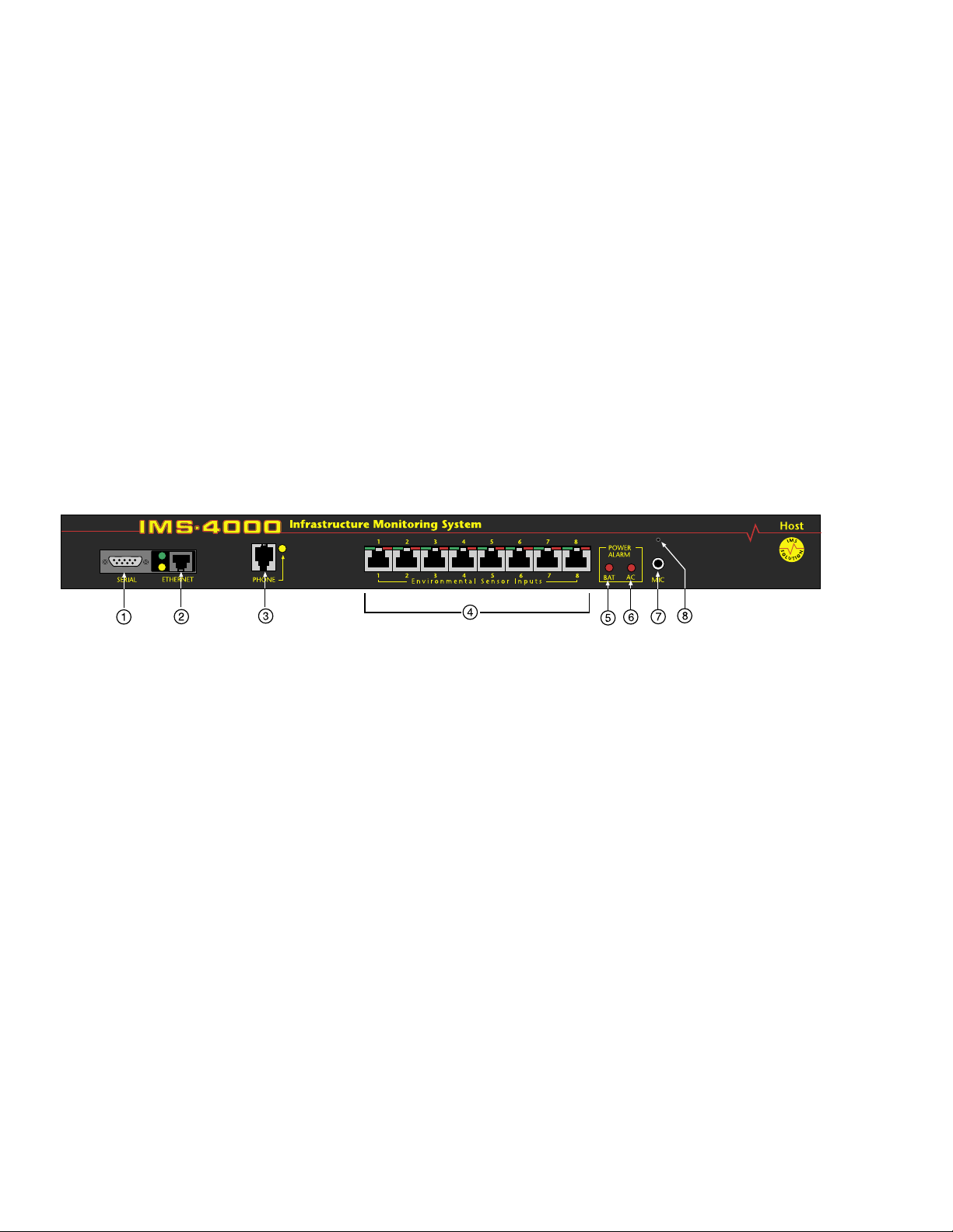
The front panel contains connections for eight sensor inputs, microphone input, Ethernet port, serial
port, and status LEDs. See figure below:
Figure 1: Front Panel Layout of the IMS-4000 Host
1 Serial Port
2 Ethernet port (10/100Base-T)
3 Phone line
4 Sensor Inputs (8)
5 Battery Power Alarm LED
6 AC Power Alarm LED
7 External Microphone Input
8 Internal Microphone
Serial Port
The RS-232 serial port is used to configure network settings. The port operates at 9600 baud, no
parity, and 1 stop bit.
RJ-45 10/100BASE-T Ethernet Port
This jack is for connecting to your network so that the IMS-4000 Host can communicate with the
IMS-4000 Nodes and ping selected network servers and/or services. Two LEDs indicate received
data (green) and transmitted data (yellow).
20
Page 21

Chapter 1: Installation
Phone Jack
Connect the IMS-4000’s Phone jack to a standard 2-wire analog phone line. The unit dials using
touch-tones, with loop start only. The IMS-4000 will recognize ringer frequencies from 16 to 60 Hz
and will operate with all standard analog telephone systems that accept tone dialing.
Certain private telephone systems and public switching equipment may not accept the unit’s dialing
or may generate an unacceptable ring signal. In those cases, a dedicated line may be required for
the unit. Consult the supplier of your telephone system if you encounter problems.
CAUTION: Never install telephone wiring during a lightning storm. Never install telephone
jacks in wet locations unless the jack is specifically designed for wet locations. Never touch
uninsulated telephone wires or terminals unless the telephone line has been disconnected at the
network interface. Use caution when installing or modifying telephone lines.
Sensor Inputs
The sensor inputs are designed to interface with IMS-4000 series sensors (See Chapter 6). The use
of RJ-45 jacks for sensor inputs allows the use of existing structured cabling to connect remote sen
sors.
Since the sensor produces an analog signal, it must connect directly to the Host or Node. The path
from the sensor to the IMS unit CANNOT pass through a network Hub or Switch.
-
Sensor Input LEDs
Each sensor input has two LEDs (red and green) to indicate the present status of the input. The
key below describes the multiple modes of operation.
Mode 0: No sensor at input
Green: OFF
Red: OFF
Mode 1: Sensor present—No alarms
Green: ON
Red: OFF
Mode 2: Alarm detected but has not exceeded recognition time
Green: FAST BLINK
Red: FAST BLINK
Mode 3: New alarm exists and not yet acknowledged
Green: SLOW BLINK
Red: SLOW BLINK
Mode 4: Input is in normal range, but alarm is still unacknowledged
Green: ON
Red: SLOW BLINK
Mode 5: Alarm has been acknowledged, but input is still out of range
Green: SLOW BLINK
Red: ON
Mode 6: Sensor in trouble
Green: QUICK FLASH
Red: QUICK FLASH
21
Page 22
IMS-4000 Manual
AC Power and Battery LEDs
The AC Power and Battery alarm status is indicated by two red LEDs. Their modes of operation
are described below.
Mode 1: No Alarm
LED: OFF
Mode 2: Alarm detected but has not exceeded recognition time
LED: FAST BLINK
Mode 3: New Alarm exists and not yet acknowledged
LED: SLOW BLINK
Mode 4: Alarm has been acknowledged but input is still out of range
LED: ON
Microphone Jack
The Host unit comes with a built-in microphone. Directly below the built-in mic is a separate jack
for connecting an optional condenser microphone to sense audible alarms, such as smoke detectors.
When an external microphone is connected, the internal microphone is disabled.
Rear Panel
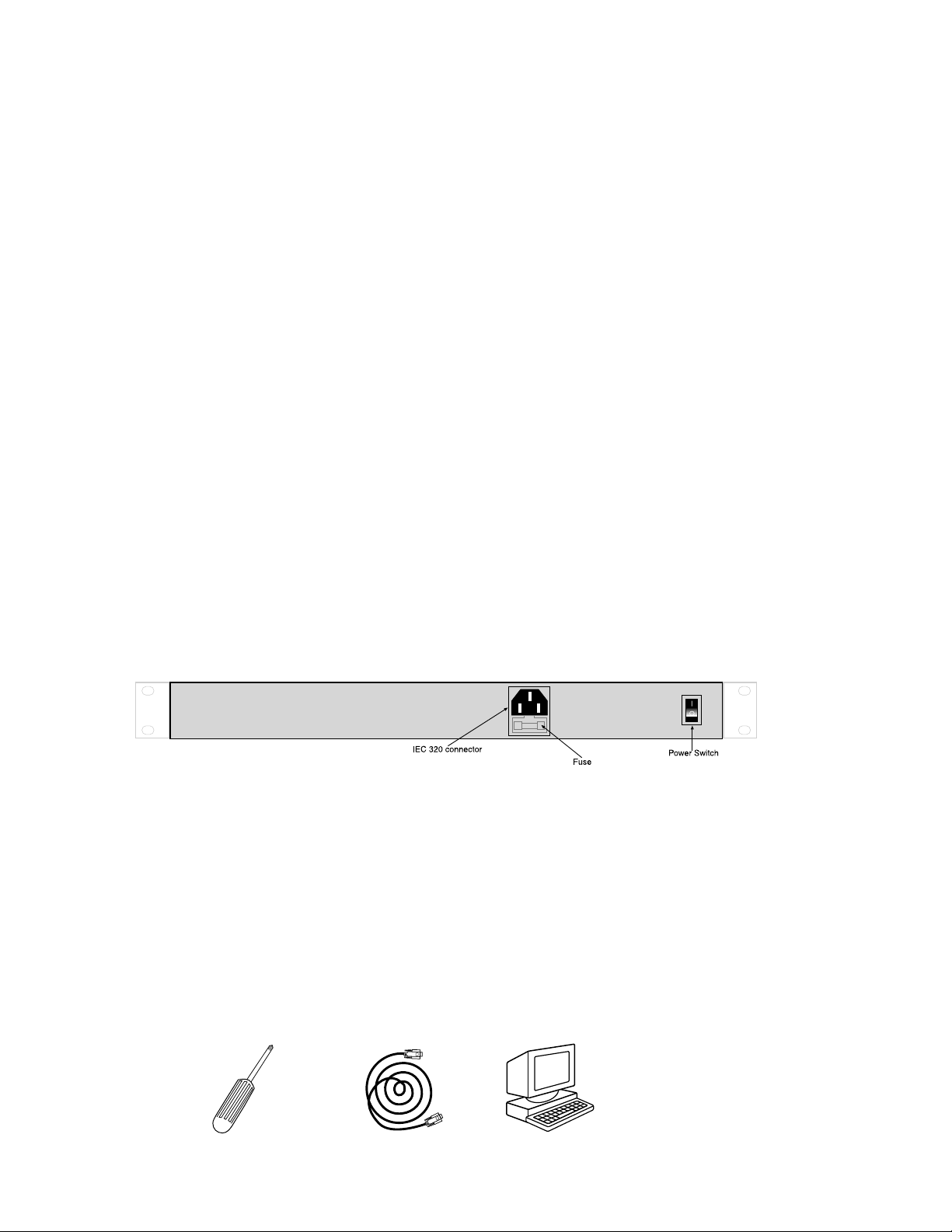
The rear panel is where the main power switch is located. The main power cord attaches to the
IEC320 connector. The unit can be powered from 90–260VAC 47–63Hz.
ON/OFF Switch
The on/off switch connects main power and battery power to the system. Note that the system will
only turn on when main power is present. When main power fails, the internal battery will auto
matically supply power to the unit.
Figure 2: Rear Panel of the IMS Host
Installation
This section provides information on:
n Operating environment
n Rack, wall, and tabletop installation
n Connecting sensors
-
Parts Required
22
Phillips 9 pin F/F null Dumb terminal or PC
Screwdriver modem cable w/9 pin com port
Page 23

Chapter 1: Installation
Operating Environment
Before you install the IMS-4000 Host be sure that your operating environment meets the physical
requirements of the equipment.
Operating Temperature: 32º –122º Fahrenheit (0º– 50º C)
Humidity: 5– 90 %RH, non-condensing
Power: 90–260VAC 47/63 Hz outlet within 6'
Rack Requirements: Standard 19' equipment rack with supplied mounting bracket
hardware. Requires 1.0 EIA rack mount space.
Tabletop requirements: Flat area which can support an enclosure 17" wide by 10" deep by 2"
high.
Rack Mount Installation
&ASEG&
23
Page 24
IMS-4000 Manual
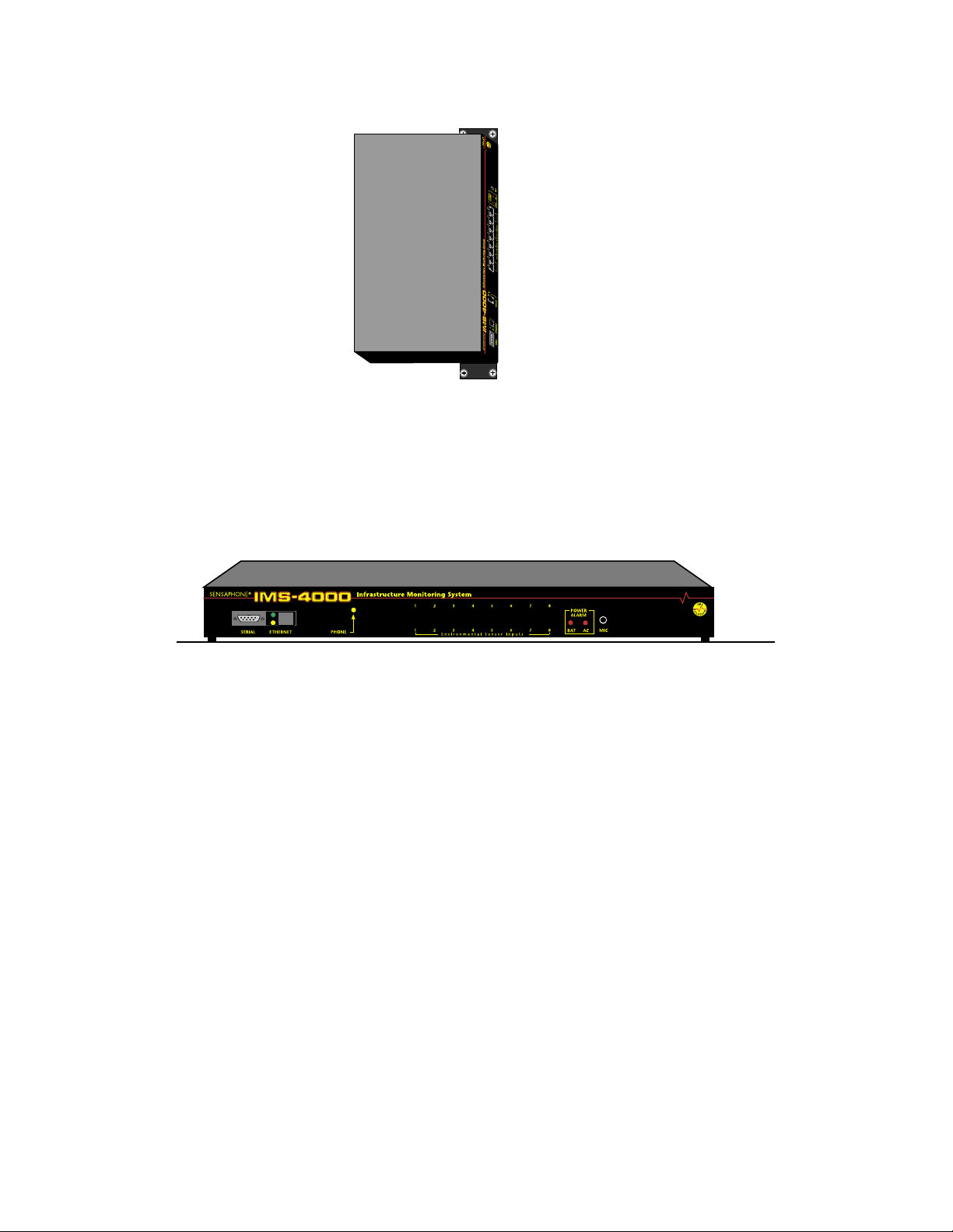
Figure 4: Wall-mounted Host Unit
Tabletop Installation
The IMS-4000 Host can be installed on a tabletop or shelf. Follow the steps below:
1) Attach the four self-adhesive rubber feet to the four corners on the bottom of the IMS-4000.
2) Place the unit on a tabletop or shelf and connect the power cord into a 90-260VAC outlet.
24
Page 25

Chapter 1: Installation
IMS-4000 installed in room A and you want to install a sensor in room B. If your existing cabling
infrastructure has an unused cable path between room A and room B, then you simply use an RJ-45
interconnect cable to connect the IMS-4000 to the patch panel in room A, and an RJ-45 interconnect cable from the wall jack in room B to the sensor.
CAUTION: The sensor produces an analog signal which must connect directly to the Host or
Node. The path from the sensor to the IMS unit CANNOT pass through a network Hub or
Switch.
Network Configuration
The IMS-4000 Host has a serial port on the front panel which is used to configure network settings
and security options. A dumb terminal or terminal emulation software is required to get online
and set up the configuration. The port is male DTE, so you will need to use a null modem cable.
Terminal communication settings must be set to:
n 9600 baud, no parity, 8 data bits, 1 stop bit
To get online with the IMS-4000, connect your terminal to the serial port and press <RETURN>.
A menu will appear which will guide you through the setup.
Sensaphone IMS-4000 Host Unit V1.0.0.0
Enter Password ()>
{The DEFAULT PASSWORD for a New Unit is “ims4k”}
1. Display Enterprise status
2. Display Network and Option configuration
3. Configure Network settings
4. Configure Enterprise Name
5. Configure Web Server
6. Configure Remote Access Server
7. Enable Two-Way E-mail Responder
8. Enable Microphone Listen-In
9. Enable default Master Administrator Account (temporarily)
0. Enable data modem
A. Configure SNMP
B. Change Admin Password
C. Reset To Factory Defaults
D. Display Statistics
E. Reboot
F. Logout
Enter option->
If you select Option 1 you will see the IP address and status of the Host and all associated nodes.
A sample is shown below:
25
Page 26

IMS-4000 Manual
Enterprise Status
Unit Type IP Status
IMS-4000 Monitor Host 10.1.4.10 Ok
NY_Node Node 10.1.4.17 Ok
Press any key to return to main menu
Option 2 will display the network configuration for the Host as well as web server, RAS, and twoway email settings. A sample of Option 2 is shown below:
Network and Option Configuration
Physical Address 00:D0:C9:37:40:86
IP Address 10.1.4.10
Subnet Mask 255.255.255.0
Default Gateway 10.1.4.1
DNS Server 10.1.2.111
Enterprise name U.S. Widgets Inc.
Web Server Enabled
Web Server Security Disabled
Remote Access Server Enabled
RAS IP Port Address 0.0.0.0
Two-Way E-mail Responder Enabled
Microphone Listen-in Enabled
Datamodem Enabled
SNMP RO community public
SNMP RW community private
SNMP Agent Enabled
Allow remote configuration Disabled
Press any key to return to main menu
Option 3 will allow you to set all pertinent network settings listed under Option 2.
NOTE: You can remotely reconfigure the Host network settings using the IMS-4000
ConsoleView software if the Allow Remote Configuration option is set to Y. However, the Host
must initially be configured via the serial port before any remote configuration is possible.
Option 4 allows you to configure or reconfigure the Enterprise name.
Option 5 allows you to configure the Web server. When Web security is enabled, a Profile
Username & Password must be entered to view the web page. A sample of the Web configuration
menu is shown below:
Configure Web Server
1. Enable Web Server: Y/N
2. Enable Web Status Security: Y/N
3. Enable Web Programming option: Y/N
4. Enable Web Programming Security: Y/N
5. Return to main menu
26
Page 27

Chapter 1: Installation
Option 6 allows you to configure the RAS (Remote Access Server). This can be used to provide
remote access to your network via a dial-up connection to the IMS-4000 Host. Note that there are
serious security risks associated with enabling this feature. A sample of the RAS menu is shown
below:
Configure Remote Access Server
1. Enable/Disable RAS Support
2. RAS IP address
3. Return to main menu
Enter option->
Option 7 allows you to Enable or Disable the two-way email feature.
Option 8 allows you to monitor on-site sound through either the built-in or an external microphone.
Option 9 (Enable default Master Administrator Account (temporarily) should only be used in the
event that no Master Administrator accounts can be accessed (e.g. the password(s) were forgotten).
Enabling this feature will temporarily load the default Master Administrator account (username:
admin, password: ims4k). This temporary account will unload if any one of the following occurs:
(1) Any of the Master Administrator accounts is edited, (2) A new Master Administrator account is
created, or (3) The system reboots.
Option 0 allows you to disable all inbound modem communications. This feature is provided for
users who cannot have a device with a modem connected to their network.
Option A allows you to program the SNMP Read-Only and Read-Write community strings.
Configure SNMP
1. Read-Only community string
2. Read-Write community string
3. Enable SNMP Agent
4. Return to main menu
Enter option ->
Press ENTER to accept new setting or ESC to cancel
Enter SNMP Read-Only community string (public) >
Configure SNMP
1. Read-Only community string
2. Read-Write community string
3. Enable SNMP Agent
4. Return to main menuEnter option ->
Press ENTER to accept new setting or ESC to cancel
Enter SNMP Read=Write community string (private) >
Configure SNMP
1. Read-Only community string
2. Read-Write community string
3. Enable SNMP Agent
4. Return to main menu
Enter option ->
27
Page 28

IMS-4000 Manual
Option B allows you to change the Local Configuration password.
Option C allows you to reset all settings to their default values.
Option D will display statistics.
Option E will save all changes and reboot the system. A reboot is required for changes to take
effect.
Option F will save all changes and logout, but the changes will not be activated until the system
reboots.
Local Configuration Definitions
Password: This is the password which protects access to the local configuration parameters.
The default password in a new unit is “ims4k.”
IP: This is the IP address assigned to the IMS-4000 on your network. This address is provided
by you or your network administrator. It is formatted as a standard dotted decimal number.
Mask: This is the subnet mask which distinguishes the portion of the IP address that is the
network ID from the portion that is the station ID.
Gateway: A TCP/IP network must have a gateway to communicate beyond the LAN identified
by the network ID. A gateway is a computer or router that is connected to two different
networks and can move TCP/IP data from one to the other. If your TCP/IP network has more
than one LAN or if you are connecting to the Internet, you will need to know the IP address
of the gateway that will transfer TCP/IP data in and out of your LAN. A single LAN that is
not connected to other LANs does not require a gateway setting.
DNS: The DNS server is used to translate site names into actual numeric network addresses.
Enter the IP address of the DNS server for your network.
Enable Web: Setting this to “
Y” will enable the web page feature of the IMS-4000. Set this to
"N" if you do not want the unit to produce a web page.
Enable Web Password: Setting this to “
Y” will require a valid user-name and password to be
entered in order to view the web page.
Enable RAS: Setting this to “
Y” will enable Remote Network Access during a dial-up
connection.
RAS IP: This is the IP address assigned to the remote computer calling in to the host.
Enable 2-Way E-mail: Setting this to “
Y” will enable the 2-way email feature. With this
feature enabled you can send commands to the IMS-4000 via e-mail and receive responses
back. Set this to "
N" to disable this feature.
Enterprise Name: The Enterprise name will appear at the top level of the IMS-4000
ConsoleView software whenever a user logs in to an IMS Host. It provides identification
consistency among multiple users and allows for future Enterprise features.
28
Enable Microphone Listen-In: Enabling this feature will allow users to listen in through the
microphone on the front panel of the unit when dialing the unit in Voice mode. Disabling this
feature will prevent the microphone from being accessed during a telephone call.
Page 29
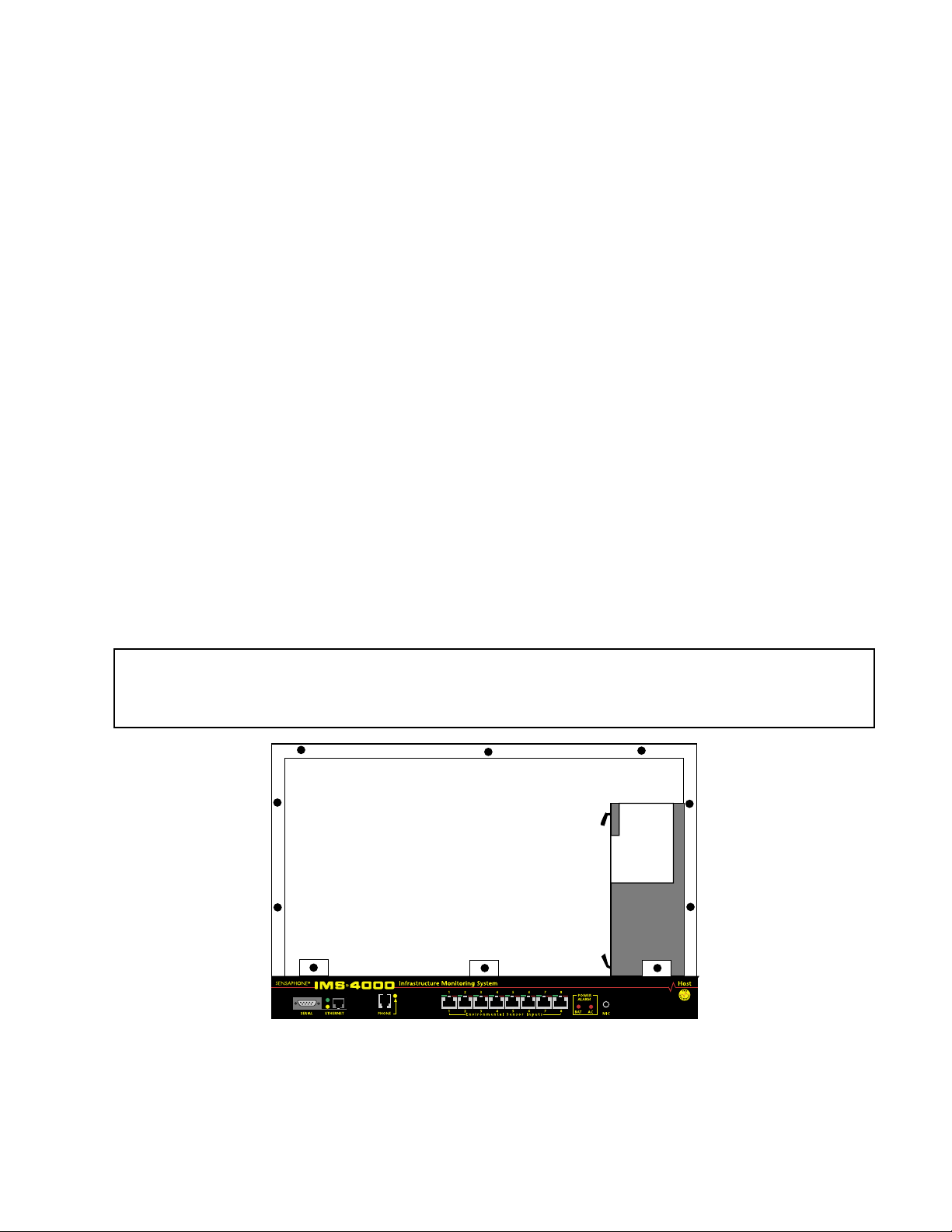
Chapter 1: Installation
Battery Maintenance
The IMS-4000 Host includes an internal UPS that automatically switches to battery backup in the
event of an AC power failure. The battery in the IMS-4000 Host is a 12V 2.9AH gel cell. This battery will keep the unit operating for approximately 3.5 hours when fully charged and under normal
operating conditions.
Service life
Over time and with periodic use, the battery will begin to lose its capacity, resulting in less overall
backup time. Under normal operating conditions, three or four years of dependable service life can
be expected or between 200 and 1000 charge/discharge cycles, depending on the average depth
of discharge. Eventually, battery replacement will be required to maintain a dependable level of
service.
Replacing the Battery
The battery in the Host can be replaced by following the instructions listed below. Be sure to read
all safety messages and follow the instructions in order as listed. Several tools will be required to
change the battery:
• small flathead screwdriver
• needle-nose pliers
• 1⁄4" nut driver
CAUTION: REPLACE BATTERY ONLY WITH A 12V 2.9AH GEL CELL BATTERY.
WARNING: DISCONNECT THE AC POWER CORD FROM THE BACK OF THE UNIT.
THERE IS A RISK OF ELECTRICAL SHOCK UNLESS YOU
DISCONNECT THE CORD.
Figure 6: Battery location
Step 1) Locate the power switch on the rear of the unit and turn the IMS-4000 off.
Step 2) Disconnect the power cord from the back of the unit.
Step 3) Remove the IMS-4000 from the rack.
29
Page 30

IMS-4000 Manual
Step 4) Remove all of the screws in the top cover. Carefully remove the top cover.
Step 5) Locate the battery on the right side. There will be a red wire (positive)
and a black wire (negative) connected to the battery. Using needle nose pliers,
remove the connector with the black wire from the battery first. Gently wiggle it off.
Step 6) Using needle nose pliers, remove the connector with the red wire from the battery.
Step 7) Using the nut driver, remove the four nuts which hold down the battery bracket.
Remove the bracket and battery.
Step 8) Install the new battery and replace the bracket.
Step 9) Attach the connector with the red wire to the positive terminal of the battery.
Step 10) Attach the connector with the black wire to the negative terminal of the battery.
Step 11) Replace the top IMS-4000 cover and secure with the screws.
Step 12) Re-install in rack.
Step 13) Re-attach the power cord.
Step 14) Turn the Power Switch back on
30
Page 31

IMS Host Specifications
Operating Specifications
Chapter 1: Installation
Host Specifications
Temperature
Humidity
Power Supply
Power Consumption
Power Connection
Dimensions
Backup Battery
Backup Time
Communications Specifications
Ethernet
RS-232
Modem
32–122° F
5–90% RH non-condensing
90–260VAC 50/60Hz
25 Watts
IEC 320
1.75"h x 9.5"d x 19"w
12V 2.9AH Sealed Gel Cell
3.5 Hours
10/100 Base-T, 10/100Mbps
DB9, 9600bps, DTE
33.6Kbps
Group 3, 14.4Kbps
Fax
Voice Processor
Environmental Monitoring
Internal Monitoring
Number of Sensor Ports
Sensor Types
Sensor Input Connector
Sensor Cables
Cable Length
Visual Indicators
External Microphone
Yes
AC Power (True RMS Voltage, Backup
Battery Level, Sound Level (in dB)
8
Temperature, Humidity, Water, Power,
Infrared Motion, Smoke, Dry Contacts
RJ-45
CAT-5, 568B
1000'
LEDs, Normal and Alarm
3.5mm jack, electret condenser
31
Page 32
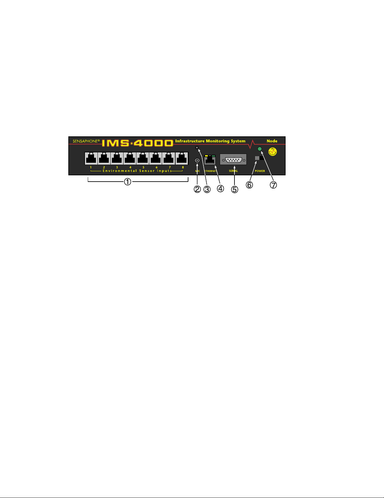
IMS-4000 Manual
NODE INSTALLATION & CONFIGURATION
Physical Description
The IMS-4000 Node is housed in a 9.6"w x 1.75"h x 7"d enclosure, which is 1 EIA rack-mount
space high.
Front Panel Layout
The front panel contains connections for eight sensor inputs, microphone input, Ethernet port, serial
port, and power LED. See figure below:
Figure 7: Front Panel Layout of the IMS-4000 Host
1 Sensor Inputs
2 Microphone Jack
3 Internal Microphone
4 Ethernet Port (10/100BASE-T)
5 Serial Port
6 Power Switch
7 Power LED
Sensor Inputs
The sensor inputs are designed to interface with IMS-4000 series sensors (See Appendix C). The
use of RJ-45 jacks for sensor inputs allows the use of existing structured cabling to connect remote
sensors.
Microphone
The Node unit comes with a built-in microphone. Directly below the built-in mic is a separate jack
for connecting an optional condenser microphone to sense audible alarms, such as smoke detectors.
When an external microphone is connected, the internal microphone is disabled.
RJ-45 10/100BASE-T Ethernet Port
This jack is for connecting to your network so that the IMS-4000 Node can communicate with the
IMS-4000 Host and ping selected network servers and/or services. Two LEDs indicate Link Status
(left) and Receive Date status (right).
Serial Port
The RS-232 serial port is used to configure network settings. The port is DB9 male DTE and oper
ates at 9600 baud, no parity, and 1 stop bit. A DB9 female–female null modem cable is required to
configure network settings.
32
-
Page 33

Chapter 1: Installation
ON/OFF Switch
The on/off switch connects main power and battery power to the system. In the event that main
power fails, the backup battery system will automatically power the system.
Rear Panel
The rear panel is where the main power cord exits the unit. A 120VAC/60Hz to 8VAC adapter provides main power to the unit.
Battery Compartment
The battery compartment is located below the top panel. The unit requires (1) 6V 3.4AH
rechargeable battery (included). To remove or replace the battery, remove the top cover with a small
flat-head screwdriver. {Note: Earlier versions of the node used six (6) C-size 2000mAHr Ni-Cad
batteries. These units can be identified by their black network jack or via software—they will be
running firmware version 2.xx or earlier.}
Installation
This section provides information on:
n Operating environment
n Rack, wall, & tabletop installation
n Connecting sensors
n Replacing batteries
Parts Required
Phillips DB9 F/F null Dumb terminal or PC
Screwdriver modem cable w/DB9 serial port
Operating Environment
Before you install the IMS-4000 Node be sure that your operating environment meets the physical
requirements of the equipment.
Operating Temperature: 32º –122º Fahrenheit (0º– 50º C)
Humidity: 5– 90 %RH, non-condensing
Power: 120VAC 60 Hz outlet within 6'
Rack Requirements: Standard 19' equipment rack with supplied mounting bracket
hardware. Requires 1.0 EIA rack mount space.
Tabletop requirements: Flat area which can support an enclosure 10" wide by 8" deep by
2" high.
33
Page 34
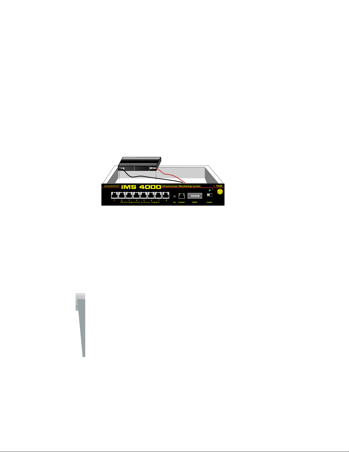
IMS-4000 Manual
Battery Replacement
The IMS-4000 Node uses one (1) 6V 3.4AH rechargeable battery (included) for backup power in
the event that main power fails. The unit will constantly recharge the battery whenever the power
switch is turned on and the unit is plugged into a power supply.
In the event you need to replace the battery, be sure to use battery part # BAT-0006 (see Appendix
C: Accessories) to ensure compatibility.
To install the new battery, first slide the power switch to the OFF position and disconnect the power
adapter. Next, remove the top cover of the unit by removing the six screws using a small flat-head
screwdriver. Remove the wire connectors from the old battery and replace it with the new one.
Reconnect the wires to the new battery and reattach the top cover.
Note: Earlier versions of the Node used six (6) C-size 2000mAhr ni-cad batteries. If you have
one of these you must use C-size ni-cads to replace them.
Figure 8: Battery replacement in the Node unit
Rack Mount Installation
The IMS-4000 Node can be rack mounted using the included rack mount brackets. Follow the
steps below:
1) Attach rack-mount brackets to the Node with a Phillips screwdriver.
2) Attach the unit to the equipment rack using two pan-head screws per side. Tighten the
screws with a Phillips screwdriver.
3) Plug the power adapter into a power outlet.
34
Page 35

Chapter 1: Installation
3) Attach the unit to the wall using two screws per side. Tighten the screws with a Phillips
screwdriver.
4) Plug the power cord into a 120VAC 60Hz outlet.
NOTE: An international version is available for 220V/50Hz operation. (Order part # IMS-
4003.)
35
Page 36

IMS-4000 Manual
Another benefit of using RJ-45 connectors is that you can easily locate sensors at distant locations
within your facility by using your existing structured cabling. For example: Suppose you have an
IMS-4000 Node installed in room A and you want to install a sensor in room B. If your existing
cabling infrastructure has an unused cable path between room A and room B, then you simply use
an RJ-45 interconnect cable to connect the IMS-4000 Node to the patch panel in room A, and an
RJ-45 interconnect cable from the wall jack in room B to the sensor.
The sensor produces an analog signal which must connect directly to the Host or Node.
The path from the sensor to the IMS unit CANNOT pass through a network Hub or
Switch.
Network Configuration
The IMS-4000 Node has a serial port on the front panel which is used to configure network settings
and security options. A dumb terminal or terminal emulation software is required to get online and
set up the configuration. The port is male DTE, so a DB9 female–female null modem cable will be
required. Terminal communication settings must be set to:
n 9600 baud, no parity, 8 data bits, 1 stop bit, no flow control
To get online with the IMS-4000 Node, connect your terminal to the serial port and press
<RETURN>. A menu will appear which will guide you through the setup.
Sensaphone IMS Node Unit Version: 2.38
Main Menu
1. Display Network configuration
2. Configure Network settings
3. Display system statistics
4. Reset to factory defaults
5. Reboot
6. Logout
Enter option->
To display the present Network Configuration settings select Option 1. To program the Network
settings select Option 2. Note that the Node must have network visibility of the Host for the IMS4000 system to function properly. For Network changes to take effect you must reboot the unit
(option 5). A typical sample is shown below:
Network Configuration
Physical Address 00:07:F9:00:10:18
Parent Host IP address 10.1.2.47
Node IP Address 10.1.4.17
Subnet Mask 255.255.255.0
Default Gateway 10.1.4.1
DNS Server 10.1.2.111
Node name 48th Floor Chicago
Allow remote configuration N
Press any key to return to main menu
36
Page 37

Chapter 1: Installation
NOTE: You can remotely reconfigure the Node network settings using the IMS-4000
ConsoleView software if the Allow Remote Configuration option is set to Y. However, the Node
must initially be configured via the serial port before any remote configuration is possible.
Option 3 will display operating statistics of the Node. This information may be useful for
troubleshooting. A sample is shown below:
Statistics
Running (hrs) 0 Disk free (KB) 209
Ram free (KB) 7136 Error mask 0
IP alarms 0 Input alarms 0
Pkt rcvs 24 Pkt xmts 4
Pkt errs 0 Ack timeouts 0
Clock timeouts 0 Socket closes 0
Socket errors 0 Socket connects 1
Avg Pkt RTT (ms) 20 Input Prog timeout 0
DSP proc starts 1 IP proc starts 1
Press any key to return to main menu
Option 4 will reset the Node to factory default settings. All programming and network settings will
be deleted.
Option 5 will reboot the system. You must reboot for new Network settings to take effect.
Option 6 will logout without rebooting.
Local Configuration Definitions
Parent Host IP Address: This is the IP address of the IMS-4000 Host that this Node is
associated with.
Node IP Address: This is the IP address assigned to the IMS-4000 on your network. This
address is provided by you or your network administrator. It is formatted as a standard dotted
decimal number.
Subnet Mask: This is the subnet mask which distinguishes the portion of the IP address that is
the network ID from the portion that is the station ID.
Default Gateway: A TCP/IP network must have a gateway to communicate beyond the LAN
identified by the network ID. A gateway is a computer or router that is connected to two
different networks and can move TCP/IP data from one to the other. If your TCP/IP network
has more than one LAN or if you are connecting to the Internet, you will need to know the IP
address of the gateway that will transfer TCP/IP data in and out of your LAN. A single LAN
that is not connected to other LANs does not require a gateway setting.
DNS Server: The DNS server is used to translate site names into actual numeric network
addresses. Enter the IP address of the DNS server for your network.
Node Name: This name will appear in the IMS-4000 ConsoleView Software. In systems with
many Nodes, the Name is useful for identifying one node from another.
37
Page 38

IMS-4000 Manual
Node Specifications
Operating Specifications
Temperature
Power Supply
Power Consumption
Dimensions
Backup Battery
Backup Time
Communications Specifications
Humidity
Ethernet
RS-232
32–122° F
5–90% RH non-condensing
120VAC 60Hz
10 Watts
1.8"h x 7.0"d x 9.6"w
(1) 6V 3.4AH sealed rechargeable
3.5 Hours
10/100 Base-T, 10/100Mbps
DB9, 9600bps, DTE
Environmental Monitoring
Internal Monitoring
Number of Sensor Ports
Sensor Input Connector
External Microphone
Sensor Types
Sensor Cables
Cable Length
AC Power, Backup Battery Level, Sound
Level (in dB)
8
Temperature, Humidity, Water, Power,
Infrared Motion, Smoke, Dry Contacts
RJ-45
CAT-5, 568B
1000'
3.5mm jack, electret condenser
38
Page 39

Chapter 2: Software
Chapter 2: IMS-4000 Software
Introduction
This chapter is designed to help you program and use the IMS-4000 to its fullest potential. The
IMS-4000 system helps you maintain, monitor, expedite and control the things that affect your
information infrastructure.
Help
The IMS-4000 ConsoleView Software provides an extensive Help system to supplement the documentation. Use IMS-4000 Help to access information about commands and dialog boxes. Online
help is also available simply by selecting Help from the main menu.
IMS-4000 Quick Start Guide
This section presents a useful shorthand guide to configuring your IMS-4000 System for the first
time. More detailed information on the processes covered can be found in the sections that follow.
Install Units and Configure Network Settings
Install the IMS-4000 Host and Node(s). Configure the Network settings through the serial port on
the front of the units. A terminal or terminal-emulation program can be used. Set the terminal settings for 9600bps (8, N, 1). The default password is “ims4k.”
Install Software and Log In to Host
Install the IMS-4000 software from your CD-ROM or other media. Double-click on the IMS-4000
icon on your desktop. The IMS-4000 ConsoleView screen will appear. From the main menu select
Enterprise, then Add Enterprise Group. See below:
Figure 1: Add Group
Right-click on the words IP Unknown below the enterprise name and select Set IP Address. Enter
the IP address for your IMS-4000 Host and click OK. The software will prompt you for a username
and password to log in.
Default Username and Password
For new units, the default username is admin and the default password is ims4k. The software will
now attempt to connect to your IMS-4000 Host. A progress bar will show the software retrieving
information from the Host.
Note: Do not save the default username and password, because it will be deleted automatically
once a Master System Administrator profile is configured.
39
Page 40
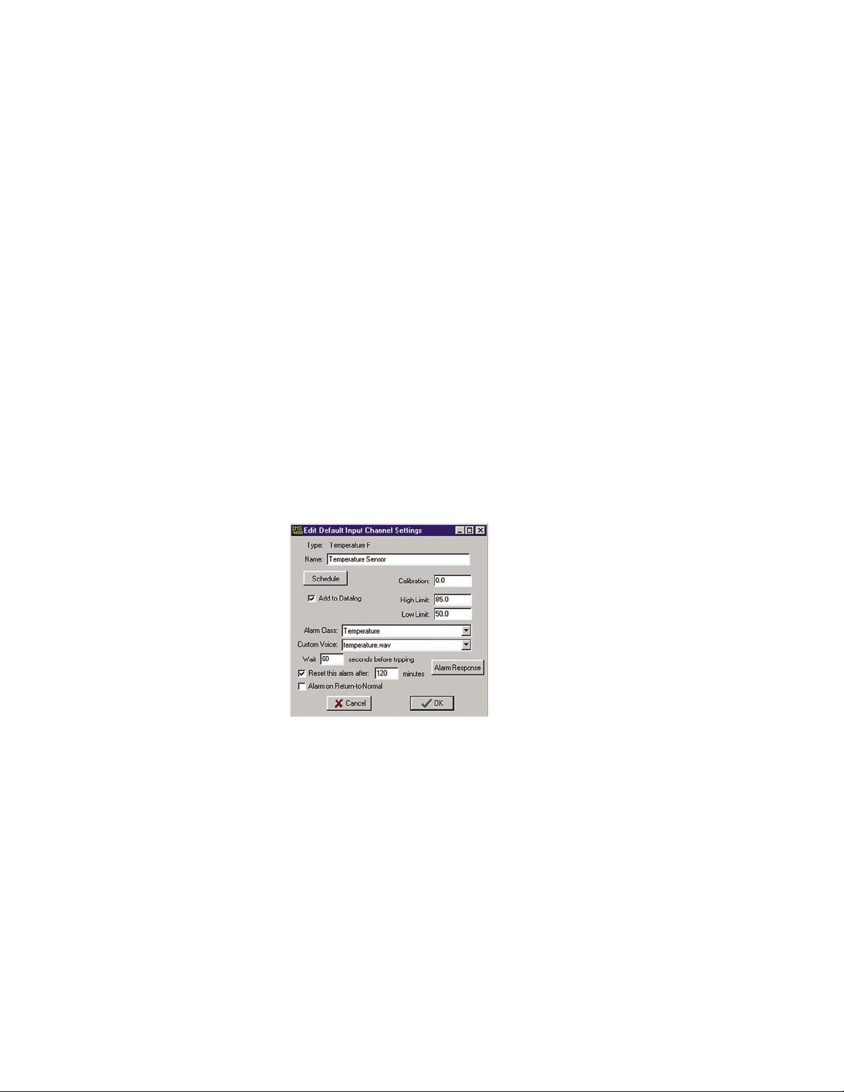
IMS-4000 Manual
Configure the Unit Properties for the Host and Node(s)
Right-click on the word Host and select Unit Properties. Step through each tabbed page and enter
the relevant information for your application. The Numeric Unit ID should be set to the Host's telephone number. Most Alphanumeric pagers work best when set to 1200bps.
The Host can synchronize its clock each night to a time server. To use this feature the IMS-4000
must have network access to a server which supports one of the following: Network Time Protocol NTP (RFC-1035), Time Protocol - TP (RFC-868), or Daytime Protocol - DP (RFC-867). Enter the
IP Address of a Time Server which supports any one of these protocols.
Expand the menus below the Host by clicking the
ciated with the Host should appear. Right-click on the Node names and select Node Properties.
Configure the Node Properties for each Node.
plus sign next to the word Host. Any nodes asso-
Configure Input Templates
Environmental input programming Templates are used to load user specified defaults each time
a new sensor is connected to a Host or Node. By properly configuring the Templates before you
plug in your sensors, you can minimize the amount of programming required to set up your sen
sors. To configure the Templates, click the plus box next to the word Settings to expand the options
under this heading. Next, expand the Input Templates. This will list all of the different sensor types.
Right-click on each of the sensor names to bring up the individual Template programming screens.
An example is shown below:
-
Figure 2: Default Input Channel Settings
Connect Environmental Sensors to Host and Node(s)
Once you've configured the Input Templates, connect your sensors. This will automatically load the
template programming for each sensor. All sensors connect to the Host and Node via RJ45 connectors. This allows you to use your existing structured cabling for wiring sensors throughout your
infrastructure.
Note: IMS sensors are not IP devices and cannot connect to Hubs or switches.
After connecting your sensors, customize the input alarm parameters for each sensor.
Configure User Profiles and Contacts
Program the User Profiles and Contacts to control who has access to the IMS-4000 and who gets
contacted when an alarm occurs. Each user must have a Username, Password, and User Code.
Right-click on Profiles and select Add New Profile. Enter information for each user. Click the
Permissions button and be sure to set up at least one Master System Administrator account. To set
40
Page 41
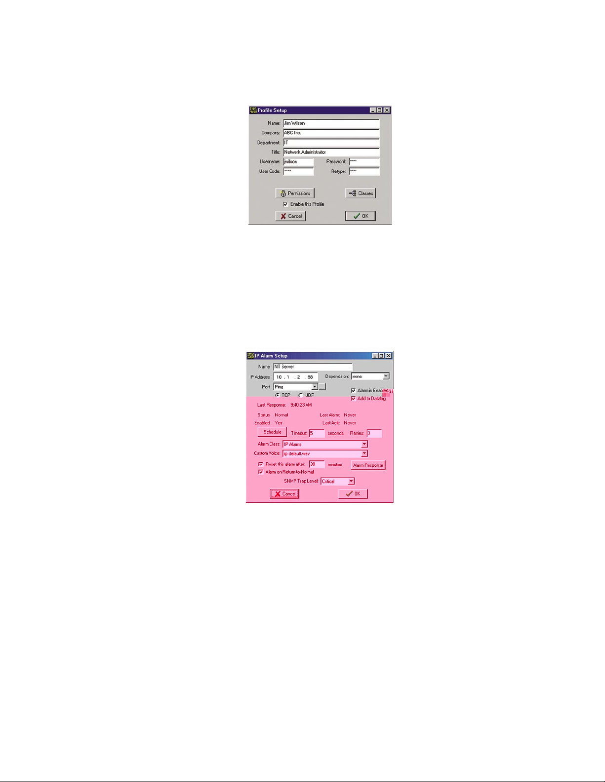
Chapter 2: Software
up alarm contact information, right-click on the profile name and select Add New Contact. You can
have up to eight contacts per user. The User Profile screen is shown below:
Figure 3: User Profile
Configure IP Alarms
Program the IP addresses for each network device you want to monitor. Expand the Host menu by
clicking the plus sign next to the name of your host. Next, right-click on IP Alarms and select Add
New IP Alarm. Enter the information to configure the network device you wish to monitor. Be
sure to enable the alarm. The IMS unit will ping/connect to the IP address and port you select about
once per minute. The IP Alarm programming screen is shown below:
Figure 4: IP Alarm Setup screen
Record and Assign Voice Messages
Custom voice messages can be used to identify your IMS Hosts/Nodes, PowerGates, Input sensors, IP alarms, and PowerGate outlets. Voice messages must first be recorded on your computer
and then uploaded to the IMS Host. Use the CustomVoice Manager screen to record and upload
your voice messages. To access the CustomVoice Manager screen, expand the Host menu and select
Voice. Note that Voice messages should be recorded at 8Khz, 8bit, mono, to keep the file size
small. See the detailed section on Recording and Uploading Voice Messages later in the manual
for more information. Voice messages are assigned to elements of your IMS unit on the respective
screens as listed below:
IMS Host Identification message - Host Unit Properties Screen
IMS Node Identification message - Node Unit Properties Screen
Input Sensor message - Input Channel Setup Screen
IP Alarms message - IP Alarm Setup Screen
PowerGate messages - PowerGate Setup Screen
41
Page 42

IMS-4000 Manual
Software Installation and Hardware Requirements
This section describes how to install and configure the IMS-4000 ConsoleView Software for your
enterprise.
Hardware and Software Requirements
Minimum Requirements:
Intel Pentium processor or equivalent
30 MB of free disk space
32 MB of RAM (64 MB RAM recommended)
®
Graphics card and monitor compatible with Microsoft Windows
®
Microsoft Windows
95, 98, NT, 2000, or XP
Mouse
Soundblaster-compatible sound card, microphone and speakers
Windows-compatible phone modem and/or RS-232 ports
95, 98, NT, 2000, or XP
Software Installation
The IMS-4000 ConsoleView Software setup program makes installation quick and easy. Make sure
that all Windows applications are closed before attempting to run setup.
If you encounter problems during installation, please call Sensaphone Technical Support at
610.558.2700.
Installing from the CD
1. Start Windows.
2. Insert IMS-4000 CD-ROM
3. Select Start>Run and type in D:\Setup.exe and click OK
Note: If your CD-ROM is installed on a drive letter other than D, substitute the appropriate
letter.
4. Follow the prompts until the installation is finished.
The IMS-4000 ConsoleView Software for Windows will install to a directory named C:\Program
Files\IMS4000, unless you choose to change the directory name. The installation program will give
you three installation choices: Typical, Compact, or Custom. For new installations choose Typical
.
.
42
Figure 5: Installation screen
Page 43
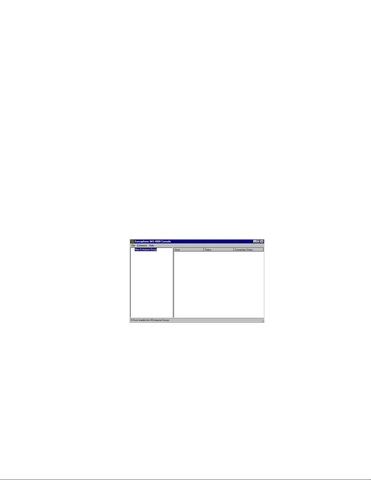
Chapter 2: Software
Starting the IMS-4000 ConsoleView Software
Double-click the IMS-4000 icon to start the IMS-4000 ConsoleView Software. The software will
automatically try to connect to all IMS-4000 Hosts that have been configured. If this is the first
time you are running the software, you will need to create an Enterprise Group and add a Host
within each Enterprise. (See Configuring Hosts and Nodes
)
Configuring Hosts and Nodes
Setting Up An Enterprise
An Enterprise Group comprises an IMS-4000 Host, any IMS-4000 Nodes connected to that Host,
and all of the environmental inputs connected to these units, regardless of proximity to the Host.
Note: Before setting up your Enterprise software, you must have locally configured your Host
and Node units—which is where you assign the Host its IP address. If you have not done this,
the ConsoleView software will not be able to locate your Host. If you are connecting to your
Host through a dialup connection, be sure to establish a PPP connection before running the
software. (See Remote Login via Dialup) See the sections in your Host and Node Manuals on
Local Configuration.
To get started, double-click on the IMS-4000 software icon. This will bring up the
IMS ConsoleView Screen.
Figure 6: IMS ConsoleView screen
Adding an Enterprise Group
From the ConsoleView menu, click on Enterprise and select Add Enterprise Group. In the left-hand
column, a New Enterprise Group will appear. When you connect to the host, the Enterprise Name
will update.
Deleting an Enterprise Group
If at any time you wish to delete an Enterprise group, click to highlight the Enterprise Group you
would like to delete, select Enterprise from the main menu and choose Delete Enterprise Group
.
Adding a Host
Right-click on the words IP Unknown below the enterprise name and select Set IP Address. Enter
the IP address for your IMS-4000 Host and click OK. The software will prompt you for a username
and password to log in. For new units, the default username is
admin and the default password is
43
Page 44

ims4k. The software will now attempt to connect to your IMS-4000 Host. A progress bar will show
the software retrieving information from the Host.
Default Username: admin
Ussm adm4kasl0ua/!Hos Ussrname
Page 45
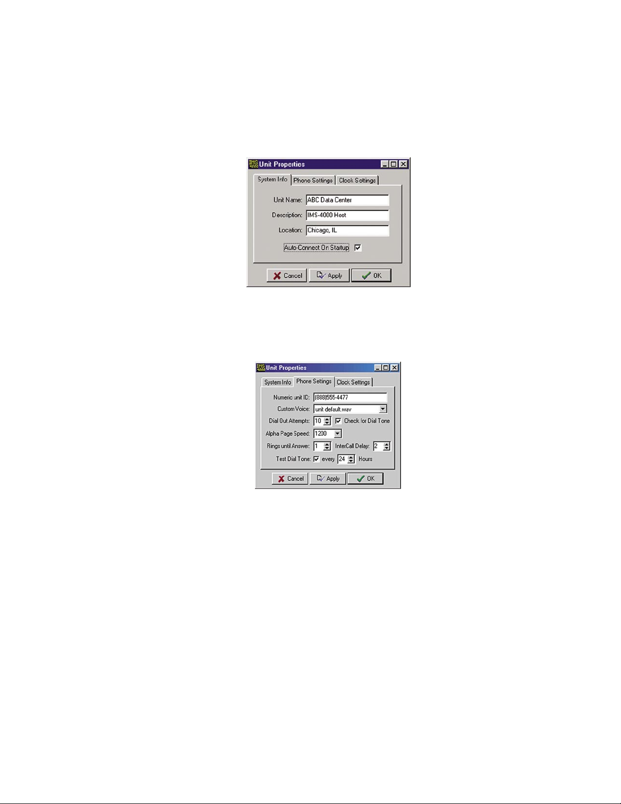
Chapter 2: Software
Setting the Unit Properties for the IMS Host
To set the global properties of your IMS-4000, right-click on the Host name and select Unit
Properties. On the System Info tab, enter the Unit Name, Description and Location. These param-
eters will be used when sending alarms to identify the unit. Check the Auto-Connect on Startup box
if you want the IMS software to connect automatically with the unit at startup. See Figure below.
Figure 9: System Info tab
Next, select the Phone Settings tab. Enter the telephone number of the Host in the Numeric Unit
ID field. The Numeric Unit ID will appear on alarm messages delivered to numeric pagers and fax
machines.
Figure 10: Phone Settings tab
Select a custom voice message to identify your Host by clicking the arrow in the Custom Voice field
and selecting a voice file. Custom voice messages can be recorded and uploaded to the Host on the
Custom Voice Manager screen. The Host Custom Voice message is the first message spoken during
a voice call. This message should describe the name and location where the Host is installed.
Enter the number of Dialout Attempts you want the IMS to make when an alarm occurs. Dialout
attempts is the number of times the IMS will try to call each contact.
Select the Alphanumeric Pager speed (Alpha Page Speed) for your paging provider. Typically, 1200
bps will work fine with most pagers.
If your phone system does not produce a dial tone when you first lift the receiver, uncheck the box
marked “Check for dial tone.”
Set the “Rings until Answer” number. This will determine how many times the line must ring
before the IMS-4000 will answer.
Set the “Intercall Delay.” This is the time the unit waits between outgoing phone calls. During this
period the unit will answer any incoming calls. To acknowledge an alarm via callback you must set
45
Page 46
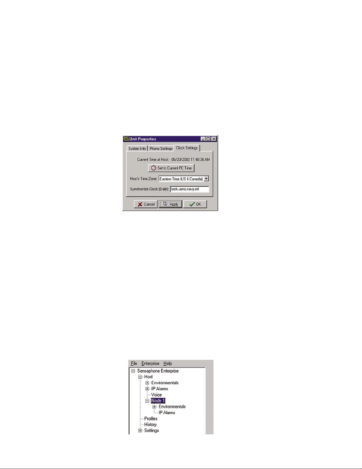
IMS-4000 Manual
this value to at least 1 minute. When set to 0 the unit will dial back-to-back calls without the possiblity of calling in to acknowledge an alarm. The Intercall Delay can be set from 0–60 minutes.
Test Dial Tone: The IMS-4000 can be programmed to test periodically for dialtone to ensure
that the telephone line is alive in the event that the unit has to dial out for an alarm. If the unit
determines that a dialtone is not present, it will send a diagnostic alarm via e-mail and/or SNMP
to profiles that are set up to receive diagnostic alarms (i.e. diagnostic class). Check to enable, then
enter the test interval, in hours, in the every X hours box.
Finally, select the Clock Settings tab. To set the time in the IMS Host, click the button labeled Set to
Current PC Time. Next, select the Host’s Time Zone according to its location. If you would like the
unit to synchronize its time on a daily basis, enter the IP address of a compatible time server.
Figure 11: Clock settings tab
The IMS-4000 can be programmed to synchronize its clock to a reference time server every night
at midnight. To use this feature the IMS-4000 must have network access to a server which supports
one of the following time code protocols:
Network Time Protocol - NTP (RFC-1035)
Time Protocol - TP (RFC-868)
Daytime Protocol - DP (RFC-867)
Click the Clock Settings tab. Enter the name or IP address of the time server in the Synchronize
Clock field. To disable this feature, delete the name or IP address.
Note: After setting the time zone, you must reboot for the new settings to take effect.
Adding a Node
Once the node has been connected to the network and the Local Configuration has been performed,
it will automatically start communicating with the Host. From the IMS Consoleview the Node will
appear within the tree. See figure below.
46
Figure 12: Structure tree with Node
Page 47
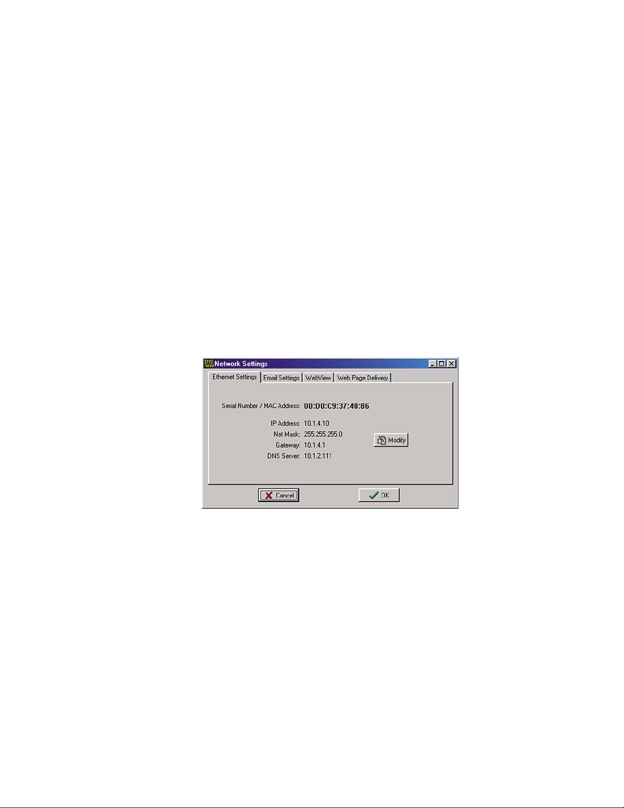
Chapter 2: Software
The Node name will appear in green when host-to-node communications are working properly.
If a communications problem occurs, the node name will initially turn yellow, to indicate that
pending node trouble exists. If the problem persists for several minutes, the node name will turn
red and a trouble alarm will be dispatched to Users who are members of the diagnostic class.
Deleting a Node
To delete a Node, right-click on the Node name in the tree and select Delete This Node.
Changing Host Network Settings using ConsoleView
You can remotely change the Host network settings using the ConsoleView software if the Allow
Remote Configuration option is set in the Local Configuration options. However, before doing so
consider the following:
If you have any Nodes associated with the Host, they will stop communicating with Host if you
change the IP address. So be sure to change the parent Host IP Address in the NODE before
actually changing it in the Host itself.
To change the network settings in the Host using ConsoleView, right-click on the unit name and
select Network Settings. The first tab is titled Ethernet Settings, click the Modify button to bring up
the Network Setup screen.
Figure 13: Host Network Settings
NOTE: If the Modify button is grey (inactive) then the unit either does not have the Allow
Remote Configuration option set, or the unit’s firmware does not support this feature and
requires upgrading.
Enter the new network parameters and click
the unit must reboot. Click OK to proceed with the change. You will be disconnected while the unit
reboots. If you changed the Host’s IP address, it will automatically change in ConsoleView as well,
so that the software will connect to your host using the new IP address.
OK. A warning message will appear telling you that
Setting the Unit Properties for the Node
To set the Properties of your IMS-4000 Node, right-click on the Node name and select Node
Properties. The Node Name will be copied from the node itself as programmed during the network
configuration procedure. Enter the Location and Description in the fields provided. These parameters will be used to identify the unit when sending alarms. Set the Custom Voice file to identify the
Node when speaking over the telephone. (See Recording and Uploading Voice Messages for infor-
mation on creating custom voice messages.)
47
Page 48
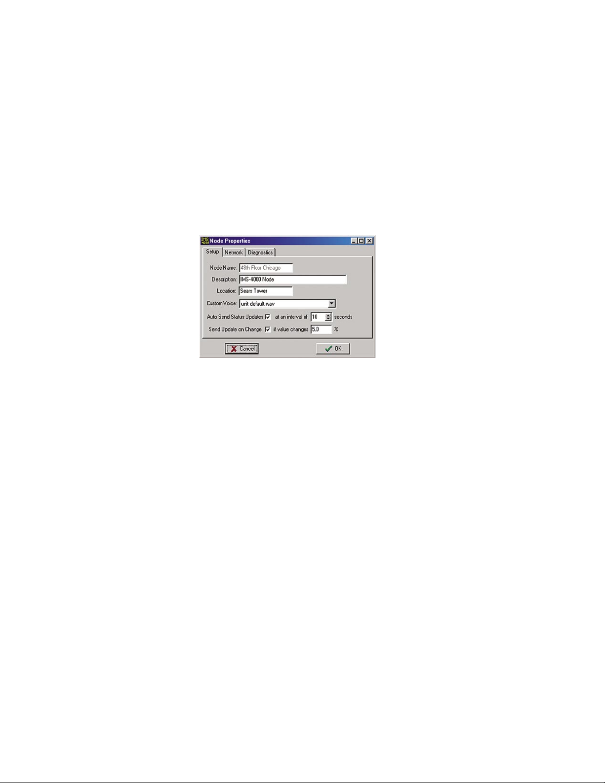
IMS-4000 Manual
In normal operation information is periodically passed between the Node and Host. This information mainly consists of current Input values and IP Alarm status. The amount of data transferred
during this update is about 700 bytes. You can choose how often information is updated from the
Node by selecting either periodic updates (Auto Send) or by selecting Update on a Percent Change
basis. This can be used to control network traffic. When you enable the Auto Send Status Updates
box, the Node will send an update (700 bytes) to the Host based on the Interval you program. When
you choose the Send Update on Change option, the Node will only send an update when a sensor
value increases or decreases by x% as programmed. You can even choose to enable both options for
more flexibility.
Note that if an alarm is detected, the Node will transmit this information to the Host immediately.
The Node Properties screen is shown below:
Figure 14: Node Properties Setup Tab
Sample Application:
1) Suppose you are concerned about network traffic generated by Node-to-Host communication but
want to view input values that are no more than 20 minutes old.
=>You can enable the Auto Send option and enter an interval of 1200 seconds (20 minutes). This
will limit Node-to-Host data transfers to no more than 700 bytes every 20 minutes.
2) Suppose that in addition, if the temperature changes by more than 3 degrees Fahrenheit (about
4% at room temperature) you want to see this update immediately.
=> You can enable the Send Update on Change option and enter a value of 4%. This will instruct
the Node to send an update if the temperature changes by +/- 4% since the last update.
Changing Node Network Settings
You can remotely change the Node network settings using the ConsoleView software if the Allow
Remote Configuration option is set in the Node Local Configuration options. However, before
doing so consider the following:
If you change the parent Host IP address in the Node, then the Node will no longer be in contact
with the Host until the Host’s IP address also changes.
To change the network settings, right-click on the Node Unit Name and select Node Properties.
Click on the Network tab. Click on the
Modify button to bring up the Network Setup screen.
48
Page 49
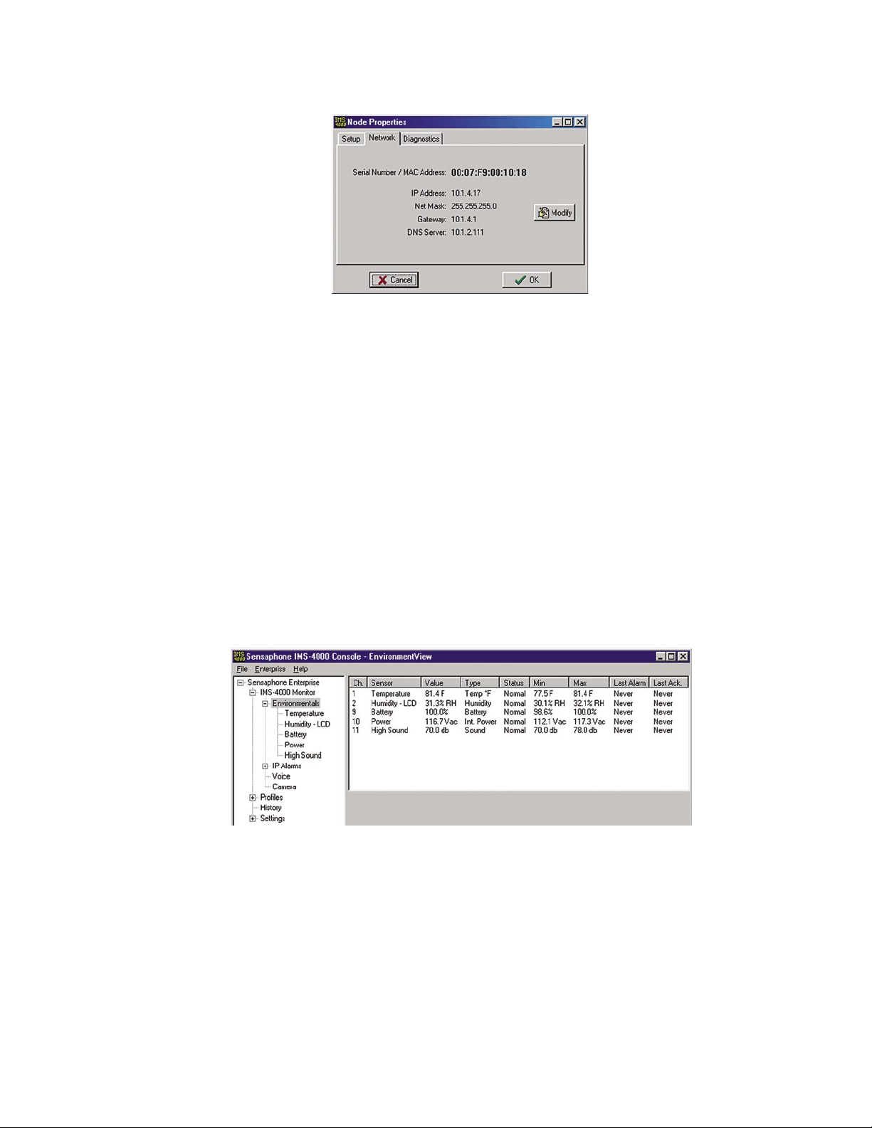
Chapter 2: Software
Figure 15: Node Network Settings
NOTE: If the Modify button is grey (inactive) then the unit either does not have the Allow
Remote Configuration option set, or the unit’s firmware does not support this feature and
requires upgrading.
Enter the new network parameters and click
OK. The Node will reboot and temporarily disconnect
from the Host.
Configuring Environmental Inputs
Each host or node can have up to 8 external sensors connected. The host or node will automatically
identify what sensor type is connected to each input. To program the environmental input parameters expand the host or node tree by clicking the plus box next to the host/node name.
Channel Setup
Next, click in the plus box beside Environmentals to expand the tree below it. Choose the input you
would like to configure and right-click on the sensor name.
Figure 16: Environmental Input Channels
The Channel Setup screen will appear.
49
Page 50
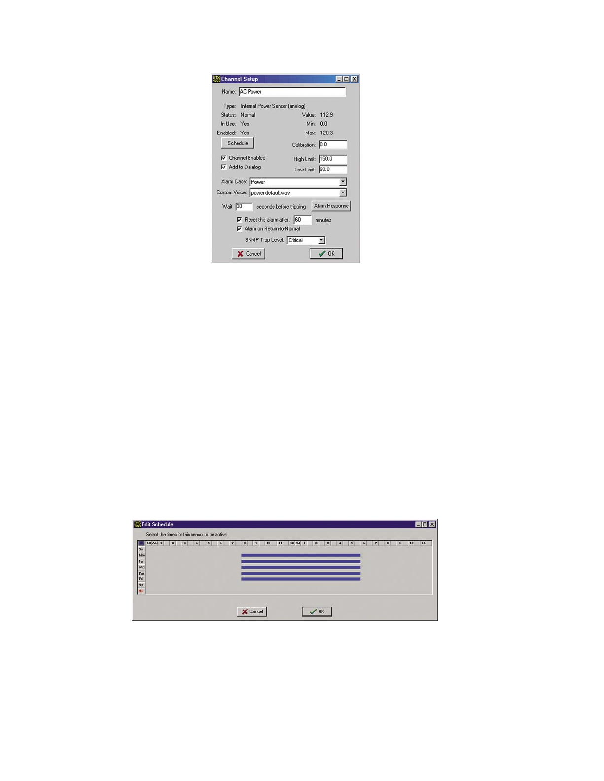
IMS-4000 Manual
Figure 17: Channel Setup screen
Set up the parameters for your environmental input on this screen.
Name: Enter a name which describes what the sensor is monitoring. (ex: Mail Server, Data
Center Rack #3, …)
Type: The sensor type is determined automatically when the sensor is plugged into the host or node.
Status: The status indicates if the sensor is presently within alarm limits. For devices such as
Water Sensors or Smoke Detectors a Normal condition indicates that there is no water or smoke
detected.
In Use: This indicates that a valid sensor is plugged into the channel.
Enabled: This indicates if the channel is currently enabled for alarm monitoring. If it is disabled,
the IMS-4000 will not send alarm messages. A channel can be enabled or disabled based on a 7day + holiday time schedule.
Schedule: Click this button to bring up the Edit Schedule screen. This screen allows you to
set times when the channel is enabled or disabled. The blue line indicates days/times when the
channel is enabled.
Figure 18: Sensor Schedule screen
The schedule example above enables the sensor Mon-Fri 8AM to 5PM.
Editing the schedule:
• Click on the All button in the top left corner of the grid to enable/disable the entire week.
• Click on the day buttons down the left side of the grid to enable/disable entire days
• Click on the hour buttons across the top of the grid to enable/disable entire hours
• Drag the mouse over portions of the grid to enable/disable specific hours/days
50
Page 51
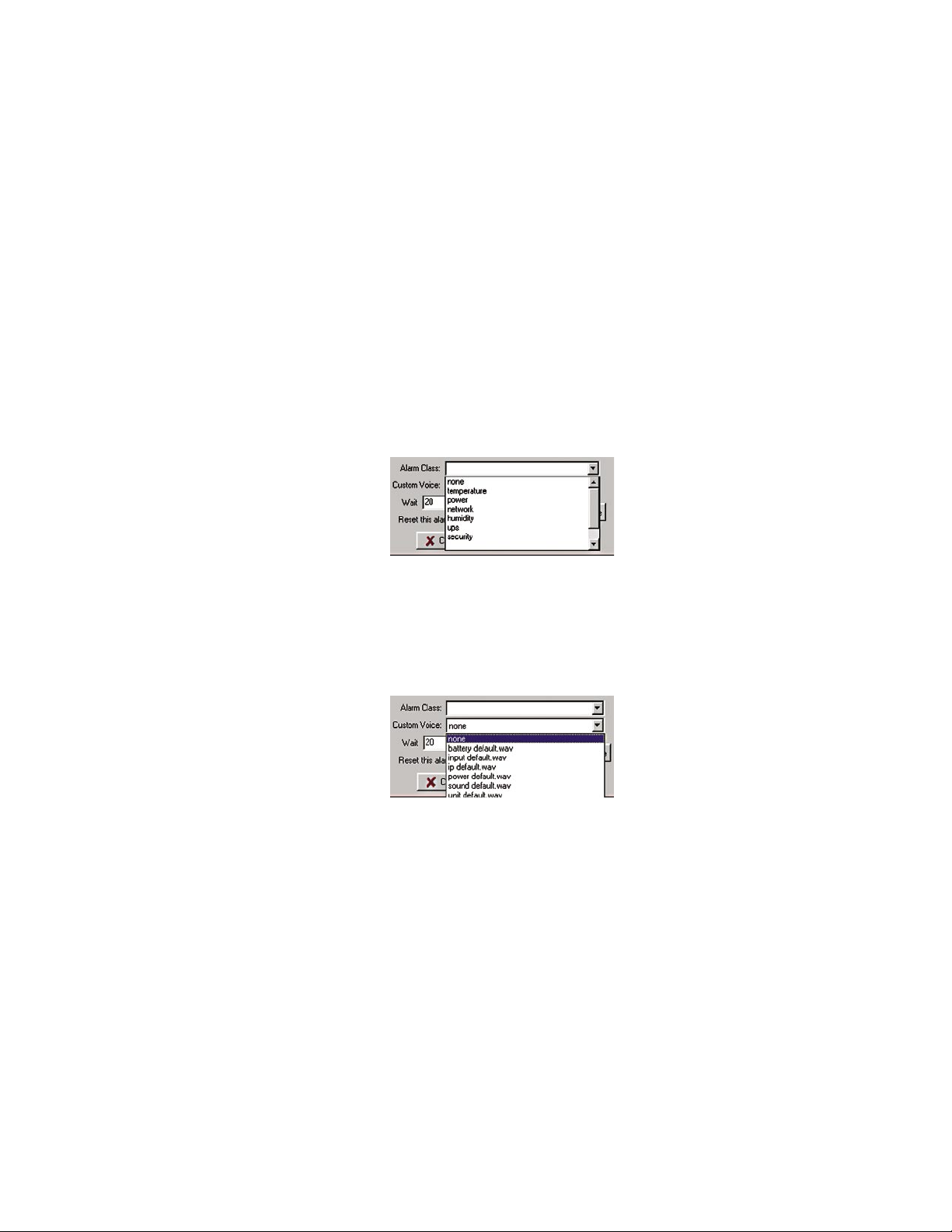
Chapter 2: Software
Channel Enabled: This box provides a simple means to enable or disable a sensor channel.
Add to Datalog: Click this box to store the value or status of the channel in the datalogger.
Value: This is the current value of the sensor connected to the channel. (only valid for analog
sensor types).
Min: This is the minimum value reached by the sensor since it was connected to the unit.
Max: This is the maximum value reached by the sensor since it was connected to the unit.
Calibration: Enter a positive or negative offset in this field to calibrate the sensor value.
High Limit: Enter the sensor high alarm limit in this field. When the value exceeds this limit for
the duration of the recognition time, and if the channel is enabled, an alarm will be tripped.
Low Limit: Enter the sensor low alarm limit in this field. When the value falls below this limit for
the duration of the recognition time, and if the channel is enabled, an alarm will be tripped.
Alarm Class: Click the drop down arrow and select the appropriate class for this sensor/channel.
If you prefer you can create your own classes on the Class Setup screen.
Figure 19: Alarm Class dropdown menu
Custom Voice: Click the drop down arrow and select the custom voice message you would like
assigned to this sensor/channel. Voice messages can be recorded on your PC and uploaded
into the IMS-4000 on the Custom Voice Manager screen (See Recording and Uploading Voice
Messages).
Figure 20: Custom Voice dropdown menu
Wait (Recognition) Time: This is the time required for a fault condition to qualify as an alarm
event. The sensor/channel must remain beyond the limits or in a fault condition continuously for
this entire period of time in order to become an alarm.
Reset Time: This is the time allowed for an acknowledged alarm’s fault condition to be corrected
before the IMS-4000 resets (reactivates) the alarm and begins the message delivery process all
over again. The minimum reset time is 30 minutes.
Alarm on Return to Normal: This feature makes the unit send a message (or messages) when a
condition has moved within its programmed alarm limits or has gone from an alarm state to a
Normal state. The person who acknowledged the alarm—in addition to all Inform Only contacts
in the alarm class—will receive the message.
SNMP Trap Level: When sending alarm messages via SNMP, this sets the priority of the SNMP
trap. The choices are Major or Minor
.
51
Page 52
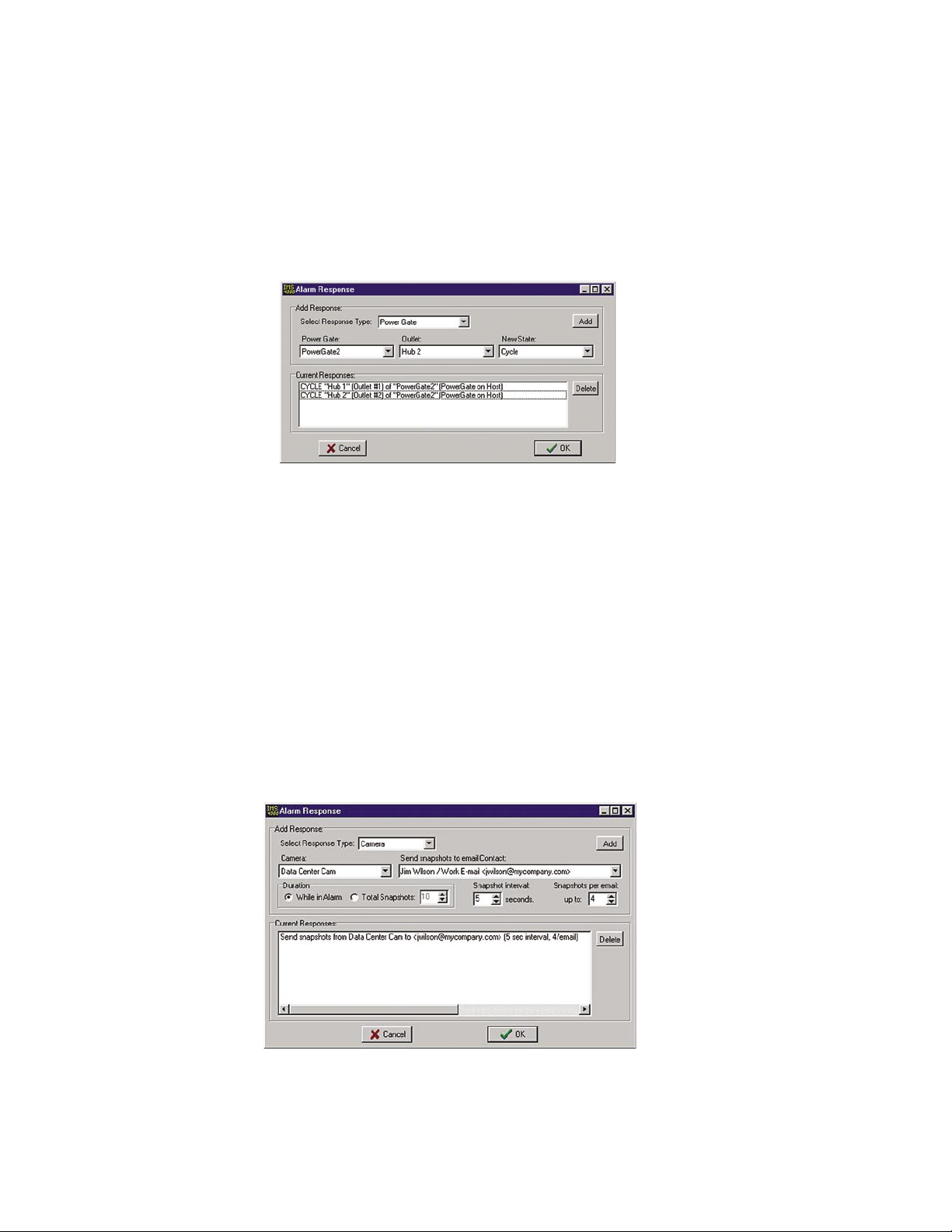
IMS-4000 Manual
Alarm Response via the PowerGate, PowerGate2, or Camera
PowerGate
When an alarm occurs, you can have PowerGate or PowerGate2 outlets automatically turn ON,
turn OFF, or CYCLE power to a device. Cycling will switch an outlet OFF for 10 seconds and
then switch it back ON. To set up a PowerGate, click the Alarm Response button on the Channel
Setup Screen. A sample Alarm Response screen is shown below.
Figure 21: Alarm Response screen for PowerGate
Select Response Type: Choose “PowerGate.”
PowerGate: Choose the specific PowerGate you’re programming.
Outlet: Choose the PowerGate outlet you want to program for alarm response.
New State: Select the action you want to have occur: On, Off, Cycle.
Click the Add button to add this response to the list of current responses; click Delete to remove an
action. Repeat for as many outlets as you wish to program.
Camera Snapshots on Alarm
Camera images may be sent to one or more users when an Environmental or IP alarm occurs. Up
to four alarm responses (PowerGate or Camera Snapshot) may be programmed per input. To configure this feature choose Alarm Response from the Properties screen for the chosen input. The
following screen will appear.
Figure 22: Camera Alarm Response
Click the down arrow in the Response Type menu and choose Camera. Select the name of the cam-
era from which you would like to receive snapshots. Next, select the E-mail address where you
would like the snapshots to be sent. There are two options to determine the Duration over which
snapshots will be sent. If you choose While in Alarm you will receive snapshots continuously until
52
Page 53
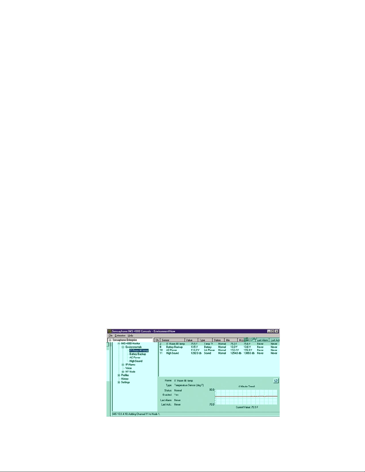
Chapter 2: Software
the input goes back to normal. If you choose Total you will receive a fixed number of snapshots
once the alarm is detected. You can also select the time between snapshots in the Snapshot Interval
field, and you can choose the maximum number of Snapshots Sent per E-mail. Camera snapshots
will not work if a User Login is required in the camera.
Note: the E-mail messages sent via Alarm Response operate independent of Profile Class and
Contact Schedule.
High Sound Alarms
The IMS-4000 measures the sound level with the built-in microphone on the front panel. This can
be useful in detecting audible alarms in close proximity to the unit. To detect alarms at a distance
from the unit, you can plug an external condenser microphone into the mic jack. Note that the
audible alarm must be more than just a periodic beep. Only alarms that produce a loud, steady or
pulsing signal (for example, smoke detector alarms) will be recognized by the IMS-4000.
The unit is programmed to trip an alarm if the sound level increases by a programmed number of
decibels. On the High Sound programming screen this parameter is listed as “Change in dB.” The
default setting is 30db. This means that if the audio level increases more than 30 dB for the dura
tion of the recognition time, an alarm will be tripped.
-
To verify that your audible alarm is capable of tripping an alarm we recommend that you perform
several tests to check the decibel increase at the IMS unit. The test should involve tripping your
audible alarm and checking the measured level within the ConsoleView Software. Using the data
obtained from your testing, you can then set the Change in db parameter appropriately.
If you are not concerned about High Sound alarms or if the unit is installed in a generally noisy
environment that could easily trip false alarms, we recommend you disable the High Sound alarm
monitoring via the Schedule.
Realtime Strip Chart
A realtime Strip Chart will show continuous values for sensors which provide an analog value. Just
click on the sensor name and the chart will appear.
The high and low scale of the chart is based on the Min and Max values. To reset Min/Max values,
click on the Reset button to the right of the chart.
Figure 23: Programmed Environmental Sensors
53
Page 54

IMS-4000 Manual
Environmental Input Alarm Logic
Each environmental input will automatically detect the type of sensor connected (temperature,
humidity, power, motion...). Analog sensors will include high and low alarm limit programming
options while two-state sensors (Normal/Alarm) will simply have a recognition time. In order for
an alarm to be dispatched, the sensor must meet the following criteria:
a) It must be Enabled—as configured through the schedule.
b) It must have exceeded the programmed high or limit, continuously, for the duration of the
wait (recognition) time. For two-state sensors it must be in the Alarm state, continuously, for
the duration of the wait (recognition) time.
c) It must be a member of a Class.
d) There must be one or more User Profiles which include this Class.
Once the alarm is dispatched, the alarm delivery process begins. (See Alarm Delivery and
Acknowledgment for details.)
Additionally, there is an option to re-trigger the alarm if it remains beyond the High/Low limits (or
in an alarm state) too long. This programmable time period is called the Alarm Reset Time. This
parameter can be set from 30 to 3600 minutes.
DO NOT set the Alarm Reset Time too short, otherwise you will continue to dispatch the
same alarm over and over resulting in numerous phone calls.
Trouble Alarms
The IMS-4000 monitors the presence of all connected sensors to insure the reliability of the system.
When a sensor is removed from a Host or Node for more than a minute, a trouble alarm is generated. All trouble alarms are a part of the Diagnostic class, so any User who wishes to receive sensor Trouble Alarm, System Diagnostic or Fault Alarms can do so by including the Diagnostic class
in their user Class List.
Removing/Changing a Sensor
Since the Host and Node monitor the presence of sensors, you must be careful when removing them
to prevent a trouble alarm from occurring. The following procedure is recommended:
a) Disable the sensor you wish to change/remove by clearing its schedule.
b) Disconnect the sensor from the Host or Node.
c) Login to the Host or Node and expand the Environmentals to display all of the inputs. Right
click on the sensor to be removed and select Delete.
A new sensor can now be connected to the empty channel.
Special Notes
To reset a Smoke detector alarm, you must momentarily disconnect it from the Host or Node, and
then reconnect it. This will silence the alarm and return it to normal operating condition.
Configuring Templates
Environmental input programming Templates are used to load user-specified defaults each time a
new sensor is connected to a Host or Node. By properly configuring the Templates before you plug
in your sensors, you can minimize the amount of programming required to set up your sensors. To
54
Page 55
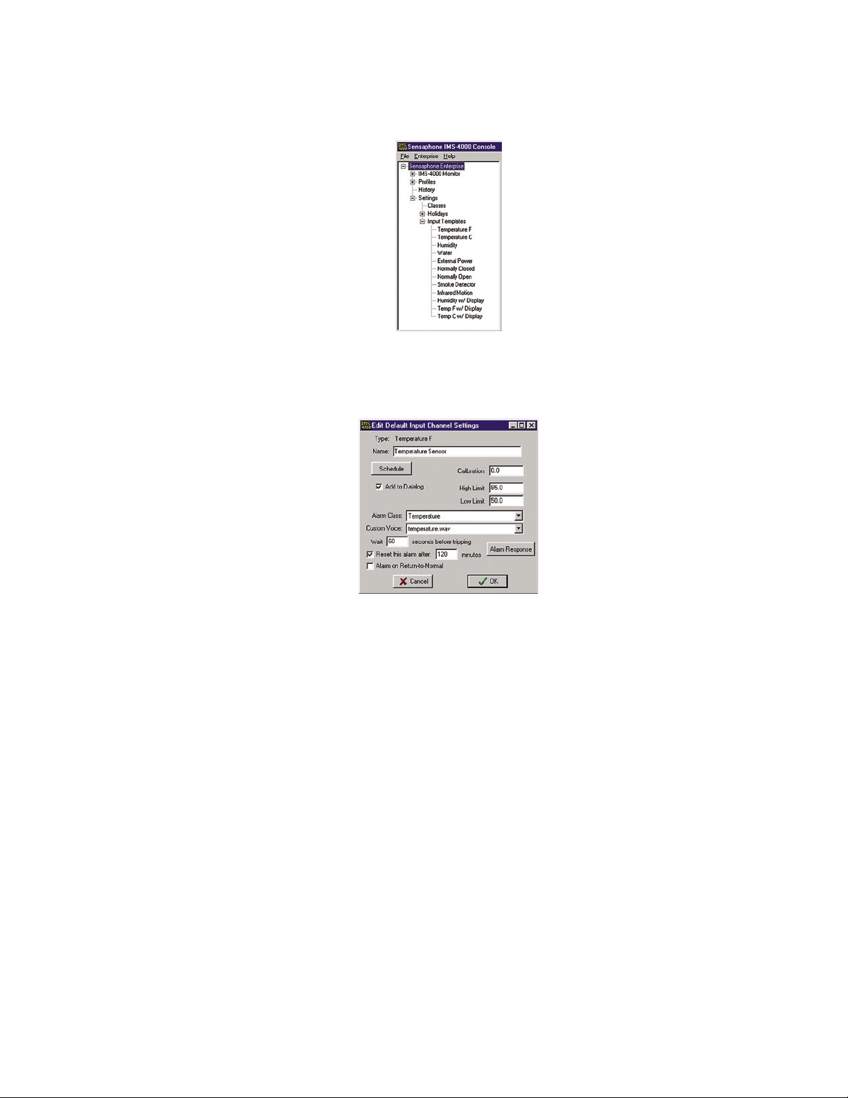
Chapter 2: Software
configure the Templates, click the plus box next to the word Settings to expand the options under
this heading. Next, expand the Input Templates. This will list all of the different sensor types.
Figure 24: Template Types
Right-click on each of the sensor names to bring up the individual Template programming screens.
An example is shown below.
Figure 25: Template
55
Page 56
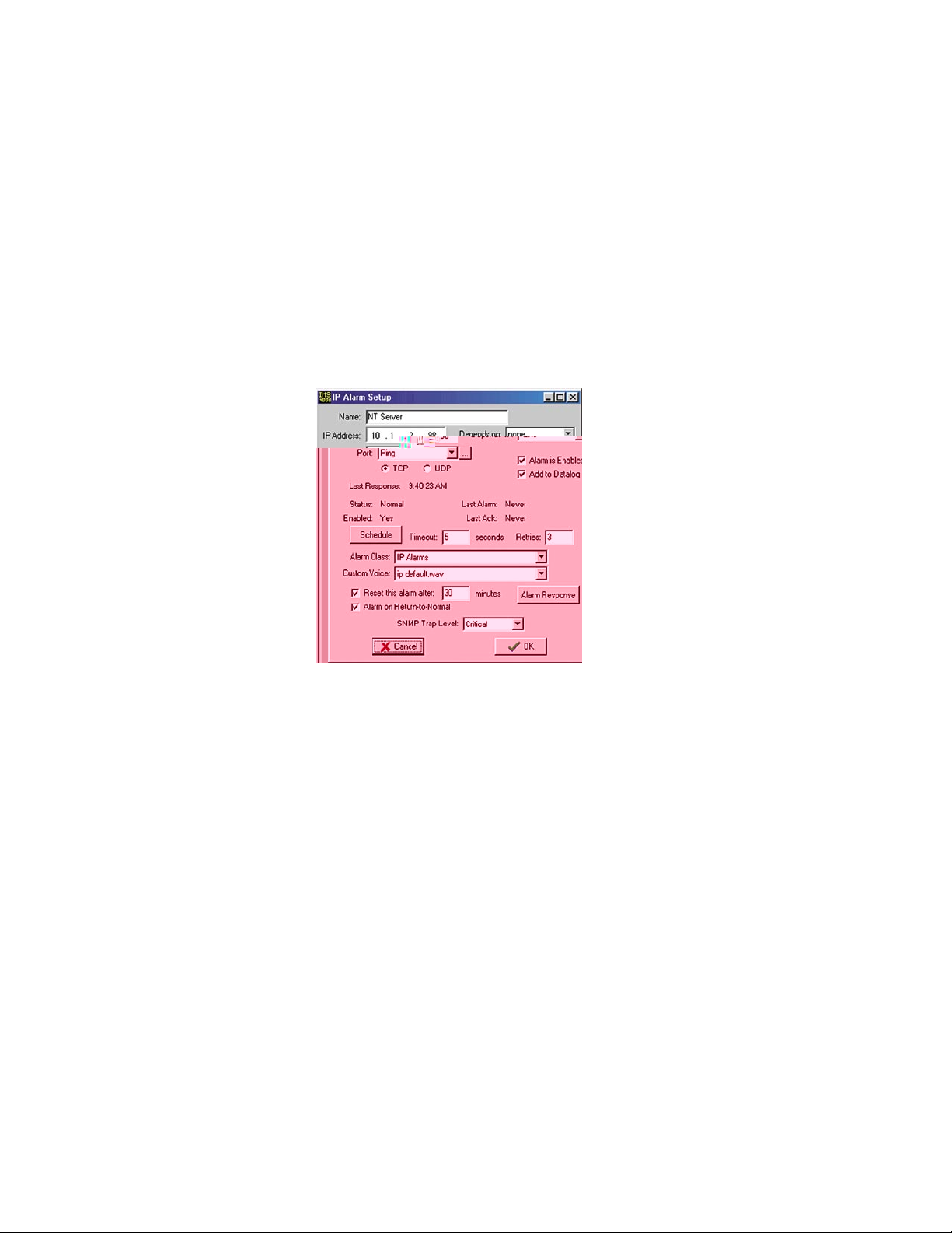
IMS-4000 Manual
Configuring IP Alarms
IP Alarm Setup
Each host or node can monitor up to 64 IP addresses through pinging and port availability. In addition, IP dependencies can be programmed to prevent multiple alarm messages from being sent
when common network paths are down.
Programming Alarm Parameters
To program the IP Alarm parameters, expand the Host or Node by clicking the plus box next to
the host/node name. Next, expand the IP Alarms. To configure a new IP Alarm, right-click on IP
Alarms and select Add New IP Alarm. Next, right click on the New IP Alarm and select Setup. The
IP Alarm Setup screen will appear.
Figure 26: IP Alarm Setup screen
Name: Enter a name which describes the IP address and port to be monitored.
IP Address: Enter the numeric IP address of the device to be monitored.
Port: Enter the port number to be monitored.
Dependency IP: This is the IP address that must be responding for the monitored IP address to
have a chance at responding. Or in other words, the monitored IP address is dependent upon the
Dependency IP address to function.
Alarm is Enabled: Unchecking this box will disable the IP alarm.
Add to Datalog: Click this box to store the value or status of the channel in the datalogger.
Last Response: This is the date/time that the IP device last responded.
Last Alarm: This is the date/time that the last IP alarm occurred for this IP address.
Last Ack: This is the date/time that the last IP Alarm for this channel was acknowledged.
Status: The status indicates if the IP Address is presently responding or not. A Normal status
indicates that the IP device is responding within the limits of the timeout and retry parameters.
A Ping Timeout status indicates that the IP device is not responding within the timeout and retry
parameters. An IP Route Down status indicates that the dependency IP is not responding and
therefore the monitored IP address cannot be reached.
Enabled: This indicates if the IP Address is currently enabled for alarm monitoring. If it is
disabled, the IMS-4000 will not send alarm messages. An IP Alarm can be enabled or disabled
based on a 7-day + holiday time schedule.
56
Page 57
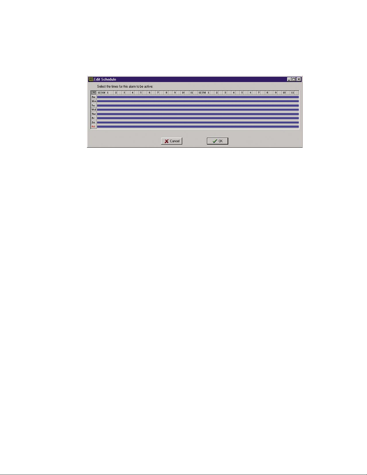
Chapter 2: Software
Schedule: Click this button to bring up the Edit Schedule screen. This screen allows you to set
times when the IP Alarm is enabled or disabled. The blue line indicates days/times when the
channel is enabled.
Figure 27: IP Schedule screen
The schedule example above enables the IP alarm 24 hours a day, including holidays.
Editing the schedule:
• Click on the
• Click on the
• Click on the
All button in the top left corner of the grid to enable/disable the entire week.
day buttons down the left side of the grid to enable/disable entire days
hour buttons across the top of the grid to enable/disable entire hours
• Drag the mouse over portions of the grid to enable/disable specific hours/days
Timeout: If the monitored IP address does not respond within this period of time, then the ping is
considered a failure. If the number of consecutive failures exceeds the number of Retries then a
Ping Timeout alarm is tripped.
Retries: This is the number of times the monitored IP address is pinged after a failure, before a
Ping Timeout alarm is tripped.
Alarm Class: Click the drop-down arrow and select the appropriate class for this type of alarm.
If you prefer you can create your own classes on the Class Setup screen to group certain types of
alarms.
Custom Voice: Click the drop-down arrow and select the custom voice message you would like
assigned to this IP Alarm. Voice messages can be recorded on your PC and uploaded into the
IMS-4000 on the Voice screen.
Reset Time: This is the time allowed for an acknowledged alarm’s fault condition to be corrected
before the IMS-4000 resets (reactivates) the alarm and begins the message delivery process all
over again. The minimum reset time is 30 minutes.
Alarm on Return-to-Normal: When this feature is enabled, the unit will send a message (or
messages) when an IP device goes from a Ping Timeout state to a Responding state. The person
who acknowledged the alarm—in addition to all Inform Only contacts in the alarm class—will
receive the Return-to-Normal message.
SNMP Trap Level: When sending alarm messages via SNMP, this sets the priority of the SNMP
trap. The choices are
Major or Minor.
Note: See the previous section, “Alarm Response via the PowerGate, PowerGate2, or Camera”
for information on responses to alarms via PowerGates or Cameras.
57
Page 58

IMS-4000 Manual
Alarm Logic
Network devices are monitored by the IMS-4000 by pinging/connecting to programmed IP
addresses about once a minute. The unit will only attempt to ping/connect to devices which are
Enabled by the Schedule. Each time the network device responds, the IMS-4000 updates the Last
Response time. A time limit for responding is assigned to each IP Alarm to determine if the device
is functioning properly. This time limit is called the ping Timeout. If a network device does not
respond within this time period, the IMS-4000 will count this as a ping failure. You can program the
IMS-4000 to try to ping/connect to the network device several times before tripping an alarm. The
ping Retries determines how many times the IMS-4000 will try to ping/connect to the device before
sending an alarm. An alarm will only occur if the device fails to respond to consecutive ping
attempts. Once a successful response is received, the failure counter will reset. For example: If the
ping Retries is set to 3, then the IMS-4000 must fail to ping/connect to the device 4 times in a row
(initial attempt + 3 retries) to trip an alarm. If the device were to respond after the second attempt,
then the failure counter would reset, thus requiring four subsequent successive failures to trip an
alarm. Once an alarm is recognized, the Last Alarm time will be updated.
A dependency device (IP address) can be programmed for each IP Alarm. This is used to prevent
numerous alarms from occurring when common network infrastructure problems arise. If the
dependency device fails, then all IP alarms that have this dependency will be temporarily disabled
from sending alarms until the dependency device returns to normal (e.g. starts responding to ping/
connect requests). When an IP Alarm’s dependency is not responding, the status for the IP Alarm
will be shown as “IP route down.” It is recommended that the dependency device be programmed
such that it will go into alarm before any other devices. You can achieve this by setting the number
of Retries for the dependency device to a lower value than the IP Alarms which rely on this device.
In summary, for an IP Alarm to be dispatched, the following criteria must be met:
a) The IP Alarm must be enabled—as configured through the schedule.
b) It must have failed to respond to consecutive ping/connect requests and exceed the number of
retries.
c) It must be a member of a class.
d) There must be one or more user profiles which include this class.
Once the alarm is dispatched, the alarm delivery process begins. If any of the contacts are pro
grammed as Until Acknowledged, then the Last Ack time will update when the alarm has been
acknowledged. In the case where all contacts are set to Inform Only, the Last Ack time will update
immediately after the alarm occurs.
Additionally, there is an option to re-dispatch the alarm if it remains in an alarm state too long. This
programmable time period is called the Alarm Reset Time. This parameter can be set from 30 to
3600 minutes. For example: Suppose the Alarm Reset Time is set to 180 minutes. Now suppose an
IP device has stopped responding and trips an alarm which results in all programmed users receiv
ing their respective messages. If the IP device continues to remain unresponsive for 180 minutes,
then the alarm will be dispatched again and everyone will be contacted once more.
DO NOT set the Alarm Reset Time too short, otherwise you will continue to dispatch the
same alarm over and over resulting in numerous phone calls, e-mails, etc.
-
-
58
Page 59
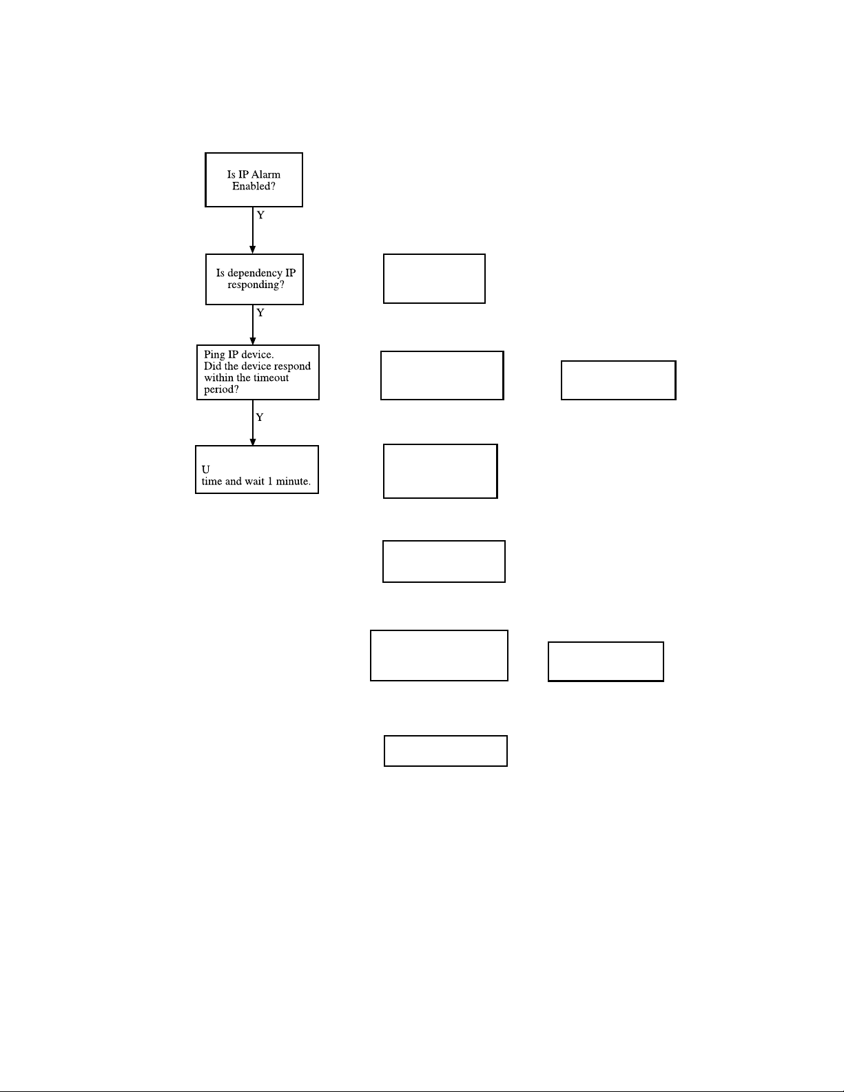
Page 60

Input/Alarm Classes
Classes are used to associate environmental inputs and IP alarms with people. Each input sensor
or IP address must be assigned to a Class. Each person or User Profile selects classes for which
thr
Page 61
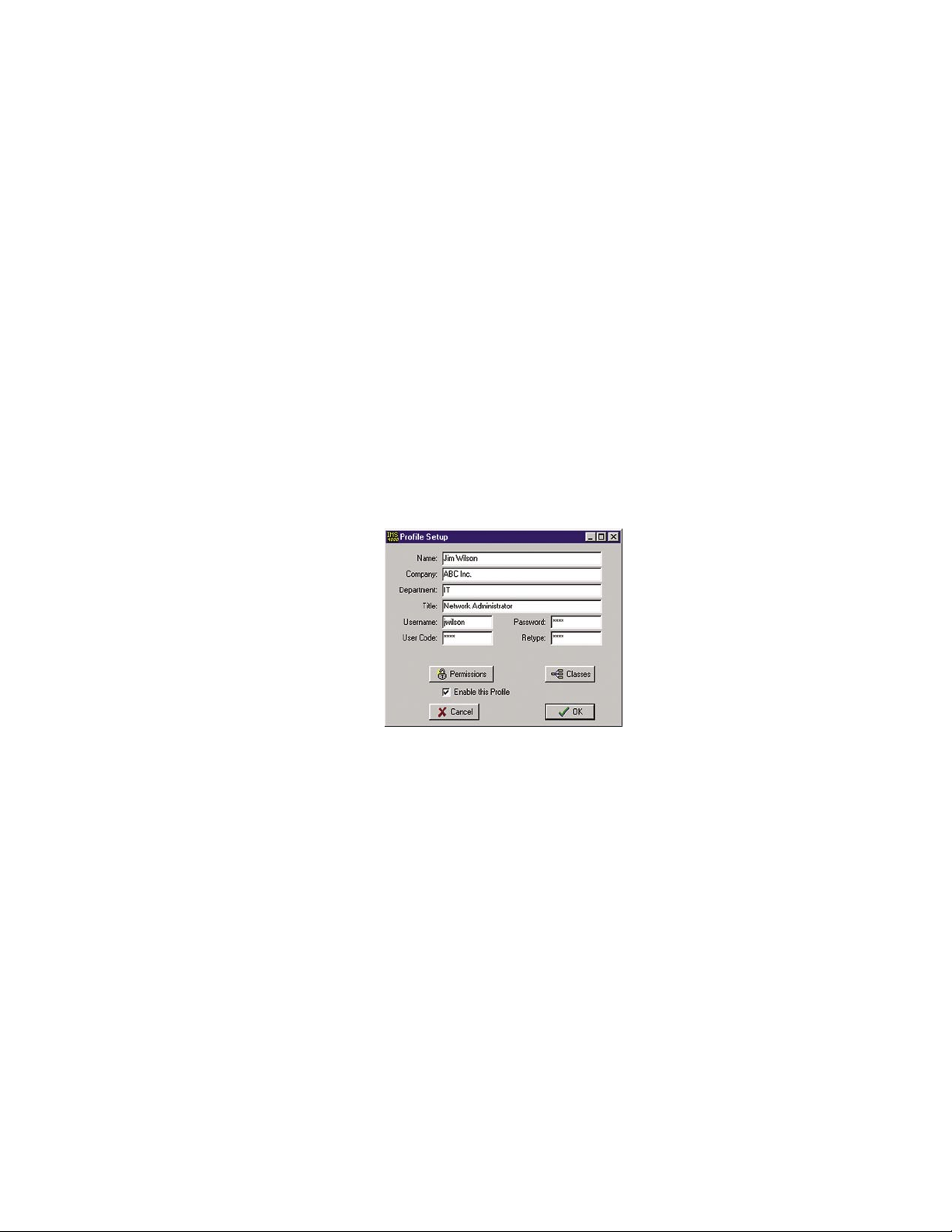
Chapter 2: Software
Configuring User Profiles and Contacts
Configuring User Profiles
The User Profile section controls who has access to the IMS-4000 and who gets contacted when
an alarm occurs. The User Profile programming screen describes attributes of the user including:
name, title, company, dept, username, password, user code, time zone, classes, etc.
When an alarm occurs the IMS-4000 will check the list of User Profiles to see who should be
contacted. Users whose class list includes the class of the alarm will be contacted. Each user can
have up to 8 contact destinations (phone numbers, e-mail addresses, …). Up to 64 different User
Profiles can be created. The IMS-4000 can contact users using 6 different methods: voice, pager,
alphanumeric pager, fax, e-mail, and snmp trap.
The order of Profiles contacted can be changed. To move a Profile up or down in the list, click and
hold the Profile you wish to move and drag it to its new location, then release the mouse button.
The Profile should now display in its new location.
Adding a Profile
Right click on Profiles and select Add New Profile. The following screen will appear:
Figure 30: User Profile screen
The Name, Company, Department, and Title information are used to identify the user on reports
that the unit sends.
The Username, Password, and User Code are used for security purposes.
You must have a Username and Password to:
• go online with the unit
• request two-way e-mail features
• access other features of the unit.
The User Code is a four digit number that is required to request a voice status report and to
acknowledge alarms. When the IMS-4000 receives a call, it will request the User Code. If a valid
User Code is entered, the unit will match this code to the User's Class List and report the status
of all Environmental Inputs and IP Alarms which correspond to the selected Classes. Voice Status
reports check User permission, and a user can only receive information on items that he has per
mission to receive. This includes environmental and IP alarm status, PowerGate switching, ping
requests, and microphone listen-in. (See “Permissions” section.)
-
The “Enable This Profile” option provides a convenient way to temporarily enable or disable a User
Profile. When a Profile is disabled (unchecked), no alarms or reports will be sent to that user, and
the user will not be permitted to log on to the system.
61
Page 62

IMS-4000 Manual
Clicking the Permissions button will bring up the Permission screen.
Permissions
Each user profile has a programmable security level for each device (host/nodes) in the system. To
set the Security Access level click the Permissions button. There are three access levels: Master
System Administrator, Site Administrator, and User. The restrictions for each security level is as
follows …
Master
System Site
Add user profiles Yes No No
Disable user profiles Yes No No
Edit unit properties Yes No No
Edit e-mail settings Yes No No
Edit Node properties Yes No No
Update firmware Yes No No
Configure data logger Yes No No
Add/delete classes Yes No No
Add/delete holidays Yes No No
Edit default input templates Yes No No
Delete sensors Yes Yes No
Disable IP alarms Yes Yes No
Reset min/max Yes Yes No
Other programming changes Yes Yes No
Add camera Yes Yes No
Acknowledge alarms Yes Yes Yes
Switch a PowerGate outlet Yes Yes Yes
Online via local PC Yes Yes Yes
Call in via voice Yes Yes Yes
Call in via modem Yes Yes Yes
Visit password protected Web Yes Yes Yes
Admin Admin User
To configure a profile as a Master Administrator simply check the box at the top of the screen.
62
Page 63
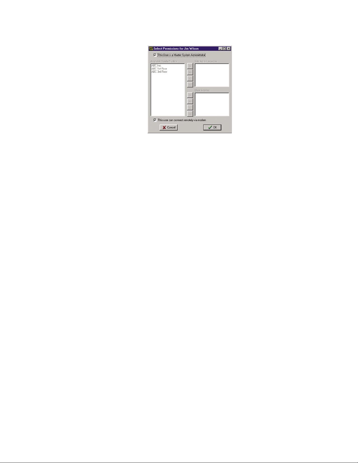
Chapter 2: Software
Figure 31: Permissions screen
To configure profiles for Site Administrator or User security levels, select the appropriate Host or
Node(s) and click the arrow to copy the Host/Node(s) into the appropriate list. The double arrow
>> will copy all units to the list while the single arrow > will copy just the selected unit to the list.
Checking the box “This user can connect remotely via modem” at the bottom of the screen, allows
the user listed at the top of the page to dial in to the system using a modem.
In addition to controlling programming access when using the IMS ConsoleView Software, permissions also have an effect during a telephone call. In voice mode the unit will recite only menus and
status information for devices that the user has permission to hear. The associated Classes for each
user will also control the content of voice reports. The same applies to two-way e-mail. A user can
only receive information or send commands if they have the proper permissions and Class associa
-
tions.
Examples:
1. If a User that has no Permissions on a particular Node, then the user will not be able to
receive any Voice or e-mail reports that contain information about that Node.
2. If a User has permissions on a particular Host/Node unit but none of the environmental
sensors are in his class, then he will not receive any information about the environmental
sensors.
Classes
Clicking the Classes button will bring up the Select Classes screen.
Selecting Classes
The User can choose to receive alarm reports from one or more Classes. The list on the left dis
plays all Available Classes. The list on the right shows Selected Classes for this profile. The Arrow
Buttons are used to select or deselect classes. See the following Arrow Button definitions and the
following figure:
-
> Move the highlighted class on the left to the right
>> Move all classes on the left to the right (select all)
< Move the highlighted class on the right to the left
<< Move all classes on the right to the left (deselect all)
63
Page 64
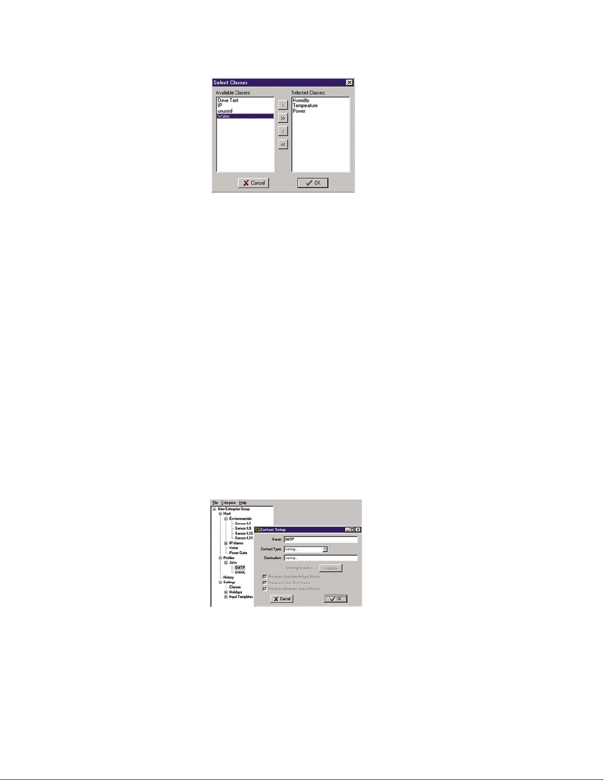
IMS-4000 Manual
Figure 32: Class Selection screen
Deleting a Profile
From the hierarchy on the ConsoleView screen, right-click on the profile you wish to delete and
select Delete This Profile in the contextual menu.
Contacts
The Contacts are the actual telephone numbers, e-mail addresses, pager numbers, etc… that the
IMS-4000 will contact when an alarm occurs. You can have up to 8 Contacts per User Profile.
Each Contact can have its own Schedule so that you can have certain Contacts be Enabled during
daytime hours and others Enabled during nighttime hours. Only Contacts which are Enabled when
the alarm occurs, will be contacted.
The order of Contacts can be changed at any time. To move a Contact up or down in the list, click
and hold the Contact you wish to move and drag it to its new location, then release the mouse
button. The Contact should now display in its new location.
Adding Contacts
To add a Contact, right-click on the User Profile you wish to add a contact to and select Add New
Contact. An entry called New Contact will appear below the User Profile. Right-click on the New
Contact and select Setup. The following screen will appear:
Figure 33: Contact Setup Screen
Enter a Name which describes the contact, like “Jim’s Cell,” “Acme Inc. Fax,” or “Jim at home.”
Select the Contact Type using the drop down arrow. The choices are: Voice, Numeric Pager, Alpha
Pager, Fax, Email, and SNMP.
Destination: Enter the Telephone Number, E-mail Address, or Server Name/Address for the contact.
64
Page 65

Chapter 2: Software
Voice Calls
For most voice calls you can simply enter the telephone number of the person you want called.
Consider the location of the IMS-4000 Host when entering the number. If an area code is required
to call from the Host to your telephone, be sure to include it.
Examples:
no area code required: 555-1234
Area code required: (610)-555-1234
1 + area code required: 1-(610)-555-1234
You can also include additional codes within the telephone number. Listed below are the special
code letters and a description of each:
p = 2-second pause
w = wait for answer
b = blind dialing (makes the unit dial and start speaking the message without requesting that
a key be pressed)
! = flashes the phone line (momentary hang-up and reconnect, useful in some PBX systems)
These codes can be useful if you want to call an extension within a business. For example, suppose
your office was answered by an auto-attendant, but you know that if you dialed the extension the
call would be transferred. In this case you can program the telephone number, insert a w to wait for
the auto-attendant to answer, and then add the extension you want dialed.
Example: 555-1234-w-170 {Extension 170 will be dialed after the auto-attendant answers}
Numeric Pager Calls
The IMS-4000 can send alarm messages to numeric pagers. It will automatically send its ID tele
phone number when dialing to a numeric pager. All you have to do is enter the telephone number of
your pager. Be sure to include the (area code) or 1 + (area code), as necessary.
Example: (301)565-2300
If your pager service is answered by a voice-prompted message, or if your pager service allows
only a few seconds to enter a number before disconnecting, you will need to enter the telephone
number differently. In this case, enter the pager telephone number + two or more pauses + the Host
ID telephone number + #.
Example: (301)565-2300-pp-844-1900-#
Alphanumeric Pager Calls
The unit can dial alphanumeric pagers to send alarm messages. The IMS-4000 uses industry stan
dard TAP protocol, which is supported by most pager systems. The IMS-4000 will send the type of
alarm, the name of the Host or Node, the Input name, the current value, the programmed high or
limit, and the time of the alarm. To program an alphanumeric pager destination, enter the pager ser
-
vice data/modem phone number followed by the letter A and then the pager ID.
Example: (610)555-4500-A-0504099
Contact your pager company if you do not know the data/modem telephone number or the pager ID
for your alphanumeric pager.
65
Page 66
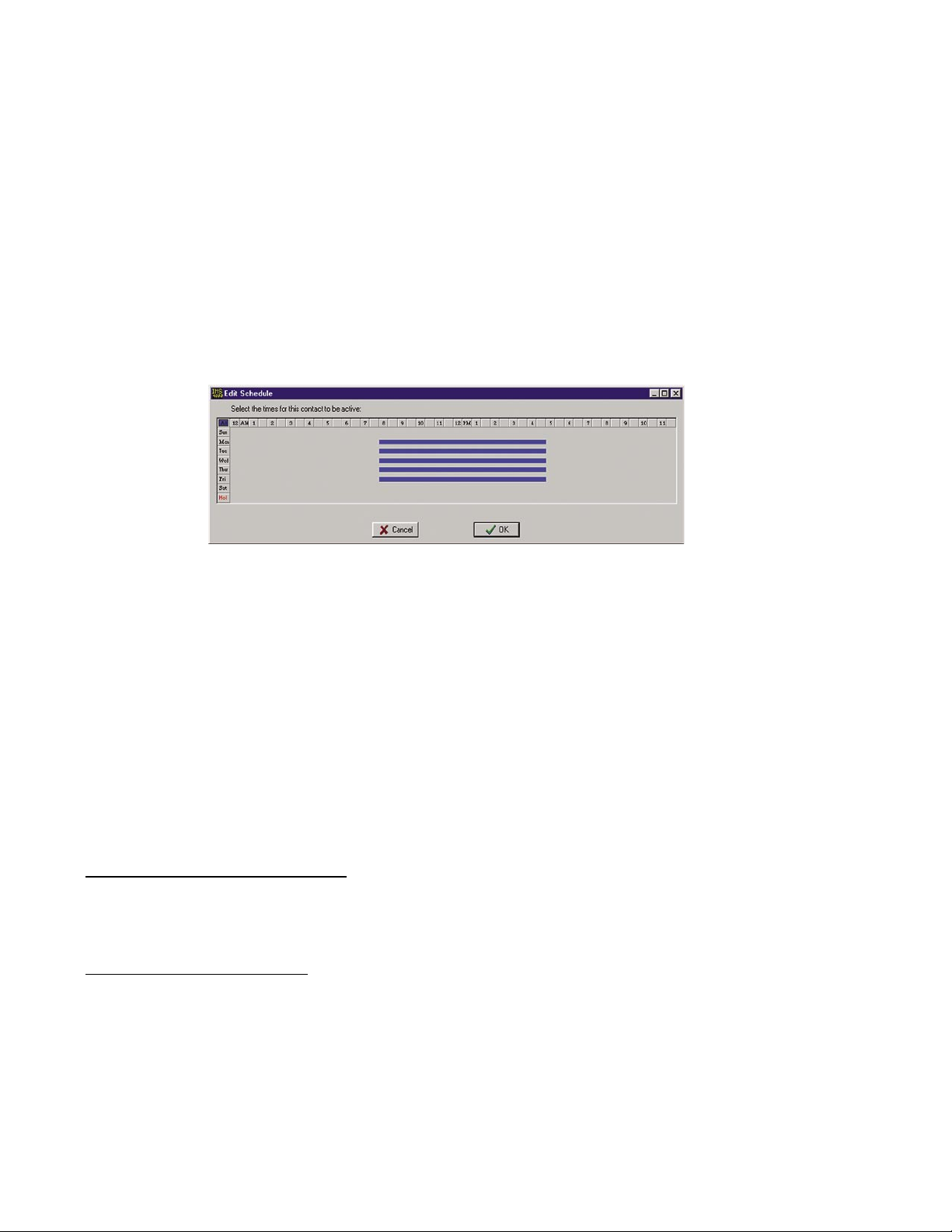
IMS-4000 Manual
Fax Calls
Enter the telephone number of the fax machine.
Enter the e-mail address.
SNMP
Enter the SNMP server IP address in numeric form (e.g. 192.168.0.1)
Schedule
Click the Schedule button to bring up the Schedule screen for this Contact. Choose the times you
want the Contact to be enabled by adjusting the blue bars. Areas where the blue bar appears indi
cates the day and time the Contact is Enabled.
-
Figure 34: Contact Schedule screen
For example, the schedule above enables the contact Mon-Fri 8AM to 5PM.
Editing the schedule:
• Click on the All button in the top left corner of the grid to enable/disable the entire week.
• Click on the day buttons down the left side of the grid to enable/disable entire days
• Click on the hour buttons across the top of the grid to enable/disable entire hours
• Drag the mouse over portions of the grid to enable/disable specific hours/days
Alarm Delivery Options
There are additional options which appear on the Contact Setup screen depending upon the type
of call. For alarm delivery you must select either Receives Unacknowledged Alarms or Receives
Inform Only Alarms or both.
Receives Unacknowledged Alarms: This option applies only to voice and pager calls. When select
ed the IMS-4000 will call this contact until the alarm has been acknowledged or until the number
of call attempts has been exhausted. If the alarm is acknowledged by another user, this contact will
stop being called.
Receives Inform-only Alarms: This means that the alarm message is for information purposes only.
Once the alarm message has been delivered, the IMS will stop calling this contact. This selection
is useful for insuring that a record of an alarm is sent. When this option is checked, the IMS-4000
will always send an alarm message to this contact.
-
66
Note: If no “Until Acknowledged” contacts are selected to receive an alarm message, the IMS
Host will self-acknowledge the alarm.
Page 67
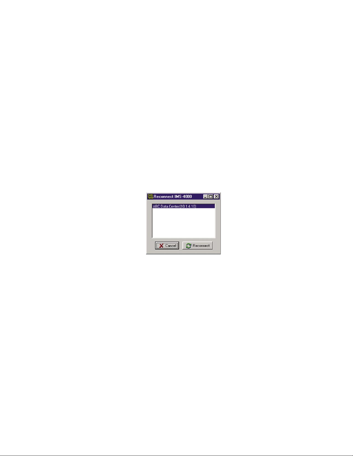
Chapter 2: Software
Saving and Loading Programming
The programming in your IMS-4000 can be saved to a file. This gives you the ability to back up
your programming or copy the same programming to another IMS-4000 unit. Note that the file you
save will not include custom voice files or settings entered through the serial port (network parameters, web settings, two-way e-mail, RAS, etc.). To save your programming to a file, right-click on
the name of your host and select Save Programming.
To load a programming file into your IMS-4000, right-click on the name of your host from the
menu tree and select Load Programming. Select a programming file to load and click the Load
button. Your unit will have to restart for the new programming to take effect. When the unit
restarts, you will be logged off. After 10 or so seconds reconnect to the unit.
Reconnecting
At times your PC and IMS-4000 Host units may become disconnected. This may happen due to a
system restart or other communication-related problem. You can reconnect to an IMS-4000 using
the Reconnect command. To reconnect to a unit, click on File from the main menu and select
Reconnect. Highlight the IP address of the unit you want to reconnect with and then click the
Reconnect button.
Figure 35: Reconnect Screen
Recording and Uploading Voice Messages
Custom voice messages can be assigned to many aspects of your IMS system. Voice messages are
used during call-in status reports and alarm dial-out. This allows the system to identify and describe
exactly where the problem is located, which equipment is affected, or which network device is not
functioning. You can assign custom voice messages to the following:
IMS-4000 Host {See Host Properties}
IMS-4000 Node {See Node Properties}
Each Environmental Input {See Channel Setup}
Each IP Alarm {See IP Alarm Setup}
Each PowerGate Device {See PowerGate Setup}
Each PowerGate Outlet {See PowerGate Setup}
67
Page 68
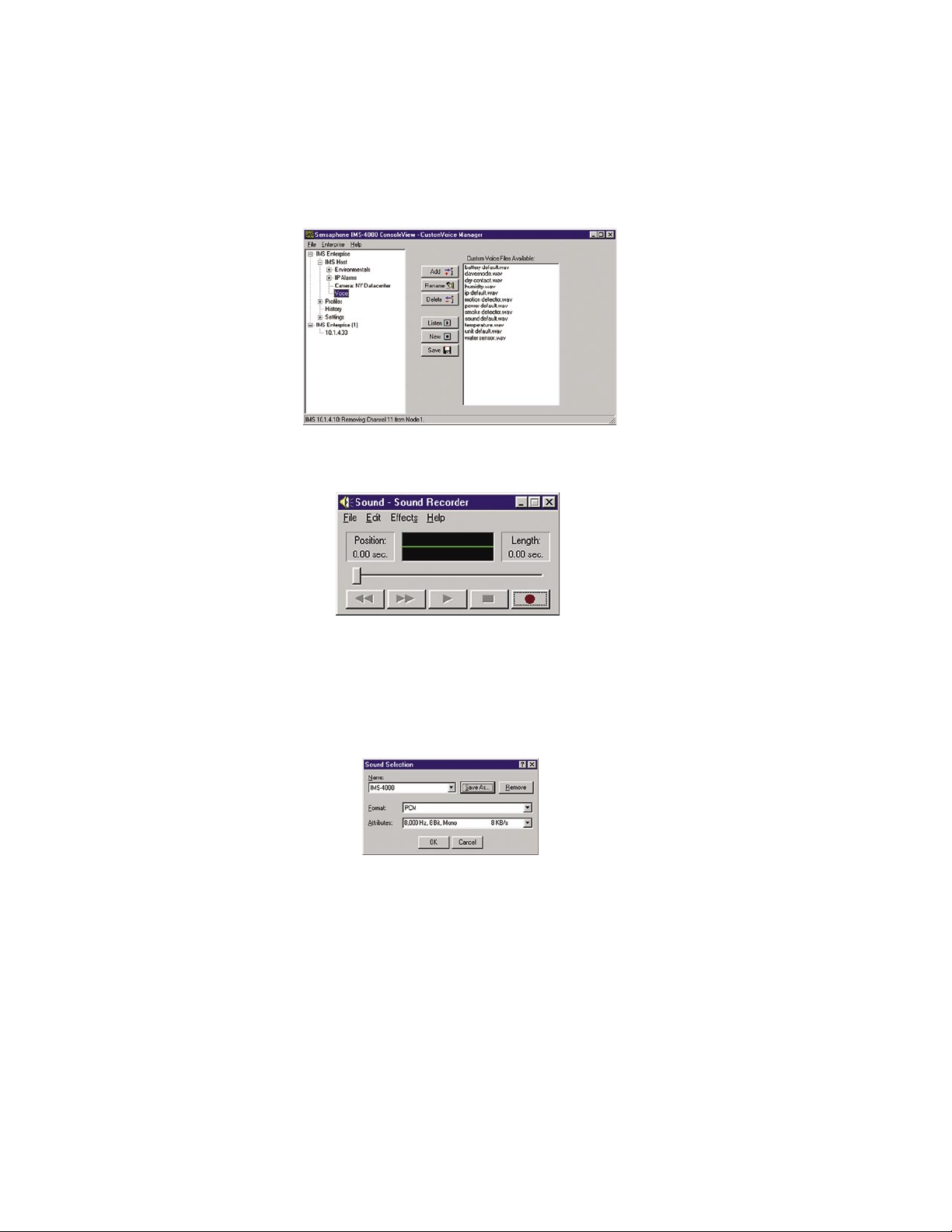
IMS-4000 Manual
Recording Voice Messages
To record voice messages, click on the word Voice from the menu tree. This will display the
CustomVoice Manager screen shown below.
Figure 36: Custom Voice Manager
Click on the New button. This will display the MS Windows Sound Recorder program shown below.
Figure 37: Sound Recorder screen
For the voice messages to play back correctly you must set the recording format to PCM, 8KHz, 8
bit, mono. To set these parameters click File, then Properties. Next, click the Convert Now button.
In the Format field select “PCM.” In the Attributes field select “8,000 Hz, 8 Bit, Mono 8 KB/s.”
See the following screen.
Figure 38: Sound Specifications screen
Next, save this recording format by typing “IMS-4000” in the Name field and click Save As. Click
OK on each screen until you get back to the Sound Recorder main screen.
To record a message, click the button with the Red circle. To play a message, click the right arrow
(Play) button. Trim off any silence before and after the message to ensure that the voice report
flows smoothly. Messages can be trimmed by sliding the message position bar and selecting Edit
from the main menu, and then either Delete Before Message Position or Delete After Message
Position. It’s important to minimize the length of the file to keep the message file size small
and also to ensure that the message plays back smoothly when inserted into the message phrases.
Once you’re satisfied with your message, save it by clicking File, then Save. Enter a name for the
voice file and click OK. Continue this process until you’ve recorded all of the messages required.
Next, upload your voice messages into the IMS-4000 by clicking the Add button on the IMS-4000
CustomVoice Manager.
68
Page 69
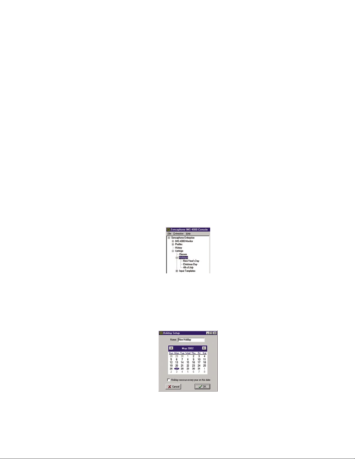
Chapter 2: Software
Select the message you would like to upload then click OK. The new voice message will be loaded
into the IMS-4000 and will appear in the list.
The window to the right displays all of the voice message file names stored in the IMS-4000.
change the file name of a voice message click Rename. Enter a new file name and click OK.
To
To delete a voice message, highlight the message and click the Delete button.
To listen to a voice message, highlight the message and click the Listen button.
Note: You must have a sound card and speakers/headphones to hear the audio.
To save voice messages from your IMS-4000 onto your computer, highlight the file name and click
the Save button. Select the folder on your computer where you would like the file saved and click
OK. This feature is useful to create a backup of the voice messages or to copy voice messages from
one IMS-4000 Host to another.
Holiday Setup
The IMS-4000 allows you to program recurring or non-recurring holidays that you can use
within your schedule programming. These schedules are used to enable or disable monitoring of
Environmental and IP Alarms, and also to enable/disable times when users will receive alarm calls.
To see which holidays are currently programmed, expand the Settings menu by clicking the plus
sign next to the word Settings, then expand the Holidays menu by clicking the plus sign next to the
Holidays. See sample below:
word
Figure 39: Holiday List
To view the programming of a particular holiday, right-click on the holiday name and select
Properties.
To program a new Holiday, expand the Settings menu and right-click on the word Holidays, then
select Add New Holiday. The new holiday programming screen will appear as shown below:
Figure 40: New Holiday
Enter a name for the holiday. Select the month, day, and year for the holiday. Finally, select whether the holiday is recurring. Click OK when finished.
69
Page 70
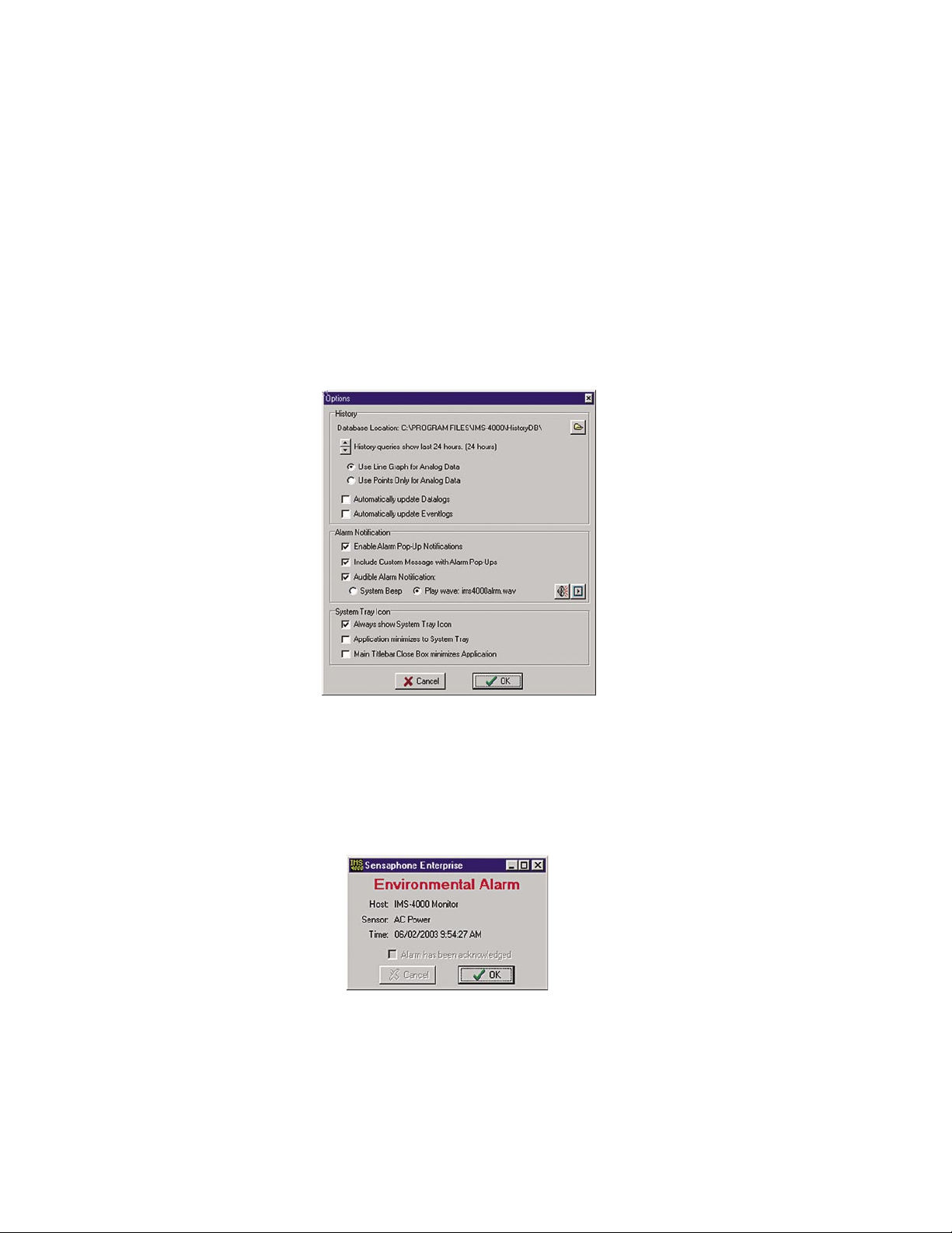
IMS-4000 Manual
Alarm Message Pop-Ups
While online with one or more IMS-4000 units through the ConsoleView Software, you can have
an alarm message pop up on your computer screen whenever an alarm occurs. This could be an
environmental or IP alarm on any Host or Node. You can configure this feature to display a general
message indicating the Unit and Channel names, or you can associate a custom message with each
input. The custom message can be displayed as plain text or HTML. The custom messages can be
stored either on the local workstation or a drive that is regularly mapped to the workstation.
Activating Alarm Pop-Ups
Click on File, then Options from the main menu in the ConsoleView Software. The following
screen will appear.
Figure 41: Options Screen
Within the section titled “Alarm Notification” click in the box to Enable Alarm Pop-Up
Notifications. This will activate the Alarm Message Pop-Up feature. When an alarm occurs, a
message will appear that simply displays the Unit and Channel names. If the user has permission
to acknowledge the alarm, an Alarm Acknowledgment box will also appear. A sample message is
shown below.
Figure 42: Simple Alarm Popup
70
Page 71
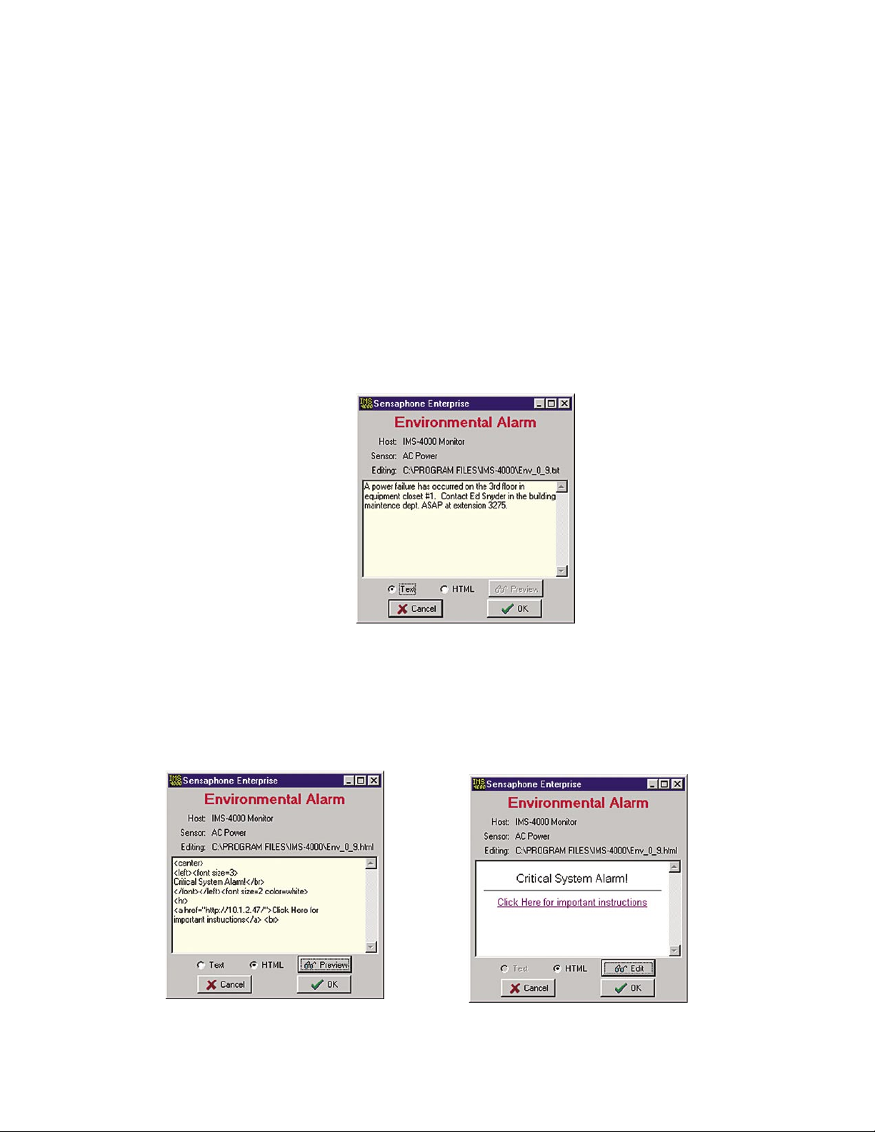
Chapter 2: Software
Enabling Custom Pop-Up Messages
To have custom messages pop up, you must enable this feature. Select Options from the main
menu. Click in the box labeled Include Custom Message with Alarm Pop-Ups. Next, you must
select where your custom messages will be stored (see below).
Setting Pop-Up Text Location
When using custom pop-up messages you must specify where these messages will be located. To
do this, right-click on the name of your host within the menu tree and select Alarm Pop-Up Notice
Location. Select the drive and folder where the messages will be stored.
Editing Pop-Up Custom Message
To edit the custom message for a particular environmental input or IP alarm, right-click on the chosen input and select Edit Alarm Pop-Up Message. The following screen will appear.
Figure 43: Edit Popup Screen
Messages can be displayed as text or HTML. Select the type of message you want to enter and type
your message into the text area. This window will scroll to accommodate lengthy actions. Note
that using HTML, you can embed web links in the message for more advanced actions. To test
your HTML code, click the Preview button. To return to the edit screen click the
Edit button. See
samples below.
Figure 44: HTML Edit Screen and HTML Preview Screen
71
Page 72
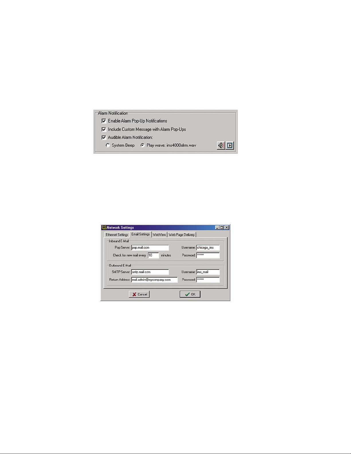
IMS-4000 Manual
Audible Alarm Notification
The ConsoleView Software can optionally beep or play a custom Wave file whenever an alarm is
detected. To utilize this feature, click File, then Options from the main menu. Under the Alarm
Notification section select Audible Alarm Notification. Next, select either System Beep or Play
Wave. If you selected Play Wave, then you must select the Wave file to be played. Click on the
speaker button to choose a Wave file. After you've made your choice, you can preview it by click
ing the Play button. See sample screen below:
Figure 45: Alarm Notification screen
E-Mail Setup and Two-Way E-Mail Commands
-
The IMS-4000 can send alarm messages via e-mail using SMTP as well as respond to commands
via e-mail. See the Two-Way E-mail section for more information on sending commands.
To set up the e-mail parameters right click on the Host name and select Network Settings. Select
the Email Settings tab to see the following screen:
Figure 46: E-mail Settings tab
To have the unit send e-mail, you need to set the SMTP Server name and the Return e-mail Address,
Username (if required) and Password (if required). To have the unit respond to Two-Way e-mail
commands you must also set the POP Server name, e-mail account Username & Password, and the
Mail Check Interval.
SMTP Error messages
If your e-mail settings are incomplete or incorrect there are some messages that will appear in the
Event History log which may be helpful.
The “Invalid Configuration” message will appear if you don’t have both the SMTP Server name
and Return Address programmed. These are the minimum programming requirements to send email. If you have at least these two items programmed and the IMS-4000 is unable to deliver the
message, then you will get the message “SMTP Server not Responding,” which essentially means
that you have one or more of the following problems:
72
Page 73

Chapter 2: Software
(a) The wrong SMTP server name programmed.
(b) The wrong username programmed.
(c) The wrong password programmed.
(d) A username is programmed but none is required.
(e) A password is programmed but none is required.
(f) All of the e-mail settings are programmed properly but the unit cannot reach your SMTP
server for network routing reasons.
(g) The unit cannot reach your DNS server and thus cannot look up the SMTP server IP
address.
(h) The DNS server IP address is programmed incorrectly in the IMS Network Configuration
settings.
Two Way E-Mail
The IMS-4000 Host has the ability to send and receive standard pop/smtp e-mail. In addition
to using e-mail as a method of delivering outbound alarm messages, e-mail can also be used for
remote access into the IMS-4000. A set of commands is available that can be sent to a 4000,
within an e-mail, that will cause the 4000 to reply back to the sending e-mail address. Commands
are available to inquire status, perform network ping and IP trace-route, and control outlets on a
PowerGate.
Note: Two-way e-mail is dependent upon User permissions. This means that the user can only
receive information on items for which he has permission. (See “Permissions” section)
In order to have the IMS respond to e-mail commands you must first obtain an e-mail address
for your IMS-4000 from your internet provider, configure the e-mail settings for your IMS Host
(see e-mail setup), and have Two Way E-mail enabled (see Host Local Configuration in the Host
Installation Manual).
Note: The username and email address used in two-way e-mail commands must match a Profile
Username and Contact. The response will be sent to the specified e-mail address.
Requesting a Status Report
To request a status report, send an e-mail message to your IMS-4000 Host with the following informa
tion:
To: <e-mail address of your IMS-4000>
Subject: ims4000
username: <valid profile username>
email: <your e-mail address>
command: status
Requesting an IP Ping
To request an IP ping, send an e-mail message to your IMS-4000 Host with the following informa
tion:
-
-
To: <e-mail address of your IMS-4000>
Subject: ims4000
username: <valid profile username>
email: <your e-mail address>
command: ping xxx.xxx.xxx.xxx
73
Page 74

IMS-4000 Manual
Requesting a Trace Route
To request an IP trace-route, send an e-mail message to your IMS-4000 Host with the following
information:
To: <e-mail address of your IMS-4000>
Subject: ims4000
username: <valid profile username>
email: <your e-mail address>
command: traceroute xxx.xxx.xxx.xxx
Requesting a PowerGate Outlet Command
To request a PowerGate Outlet command, send an e-mail message to your IMS-4000 Host with the
following information:
To: <e-mail address of your IMS-4000>
Subject: ims4000
username: <valid profile username>
email: <your e-mail address>
command: powergate "<PowerGate Name>" "<Outlet Name>" on/off/cycle
For example:
Subject: ims4000
username: jsmith
email: [email protected]
command: powergate "Gear Rack #1" "Netgear switch #3" cycle
Requesting a Picture from a Camera
You can receive an e-mail with an attached picture from any camera configured in the IMS-4000.
The picture will be captured when the IMS-4000 receives the e-mail request.
To receive a picture, send an e-mail message to your IMS-4000 Host with the following informa
-
tion:
To: <e-mail address of your IMS-4000>
Subject: ims4000
username: <valid profile username>
email: <your e-mail address>
command: camera <camera name>
For example:
Subject: ims4000
username: jsmith
email: [email protected]
command: camera NY Datacenter
74
Page 75

Chapter 2: Software
Requesting Help
You can receive a brief overview of how to use and format two-way e-mail commands, by request
ing help.
Send an e-mail message to your IMS-4000 Host with the following information:
To: <e-mail address of your IMS-4000>
Subject: ims4000
username: <valid profile username>
email: <your e-mail address>
command: help
For example:
Subject: ims4000
username: jsmith
email: [email protected]
command: help
-
Configuring a Video Camera
The IMS-4000 is compatible with the following network cameras.
Axis:
205 241Q
206 241S
206M 2100
206W 2120
210 2400 Server
211 2400+
213PTZ (unable to PTZ in Console View) 2420
2460 DVR
on image switches image to next camera)
Panasonic:
KX-HCM8 BL-C10A
KX-HCM10
KX-HCM280
These are all network video cameras that allow you to view live streaming video or capture images
to e-mail when an alarm occurs. The camera or server connects to your network via an RJ-45 jack
and supports 10/100 Mbit networks. Up to 128 cameras or servers may be associated with each
Host or Node. The IMS-4000 ConsoleView Software allows you easily to click and view live video
wherever your camera is installed.
(no Quad View as on Web page; clicking
When an Axis Camera Server is used, up to four cameras can be viewed at the same time. You can
view a single camera by clicking on the video image you want to display. If you click again, it will
return to the quad image. You can also capture a still image from either the quad or single camera
display by right-clicking and choosing Capture Image.
The first step is to get the camera running on your network. This process is independent of the
IMS-4000. Follow the instructions included with the camera to get it set up. Once the camera is
75
Page 76
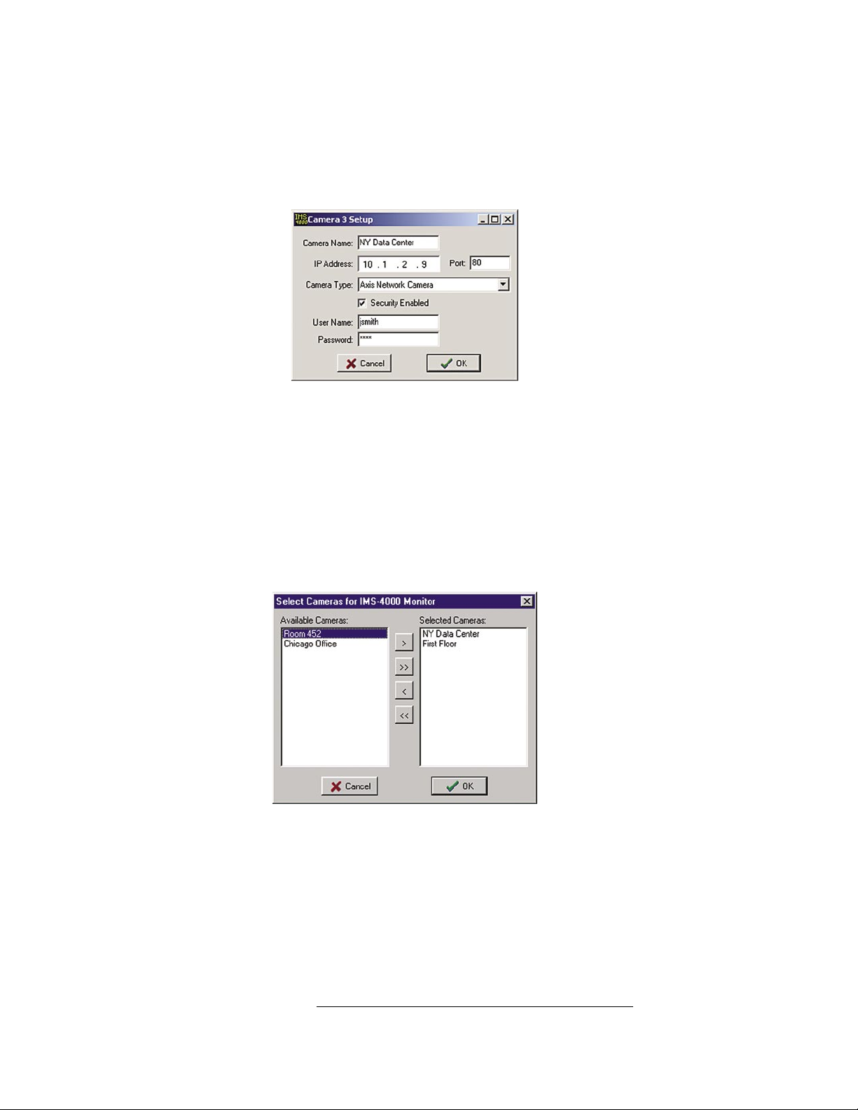
IMS-4000 Manual
properly set up, go into the IMS-4000 ConsoleView Software. Cameras are added to the IMS by
expanding the Settings menu and right-clicking on the word Cameras. Choose Add Camera. This
will bring up the Camera Setup screen (see below). Enter the IP address, port number, and security
settings (if required) of the camera according to how it has been configured on your network. See
sample screen below:
Figure 47: Camera Setup
Select the camera type by clicking on the drop-down arrow and selecting the camera. Click OK
when Finished.
Up to 128 cameras can be configured in an IMS system. These can be a mix of Axis cameras, Axis
camera servers, and Panasonic devices. Once the camera(s) have been configured they can then
be associated with a particular Host or Node so that links for these cameras will appear within the
menu tree for the chosen unit. You can associate a camera with more than one device if desired. To
associate one or more cameras, right-click on Cameras within the menu tree for the selected host or
node. See screen sample below.
Figure 48: Associating Cameras
The window on the left lists all cameras programmed into the system. The window on the right lists
cameras associated with the selected Host or Node. To move a single camera to the other window,
highlight the camera and click the single left/right arrow. To move all cameras to a new window,
simply click the double arrows. This will copy all listed cameras to the other window.
If you click on Cameras you will see thumbnails of all associated cameras. To view a large image
of a particular camera, simply click on the image.
Caution: The Panasonic and Axis cameras are Ethernet devices. They should be connected
to your Ethernet network only. They do not connect directly to your IMS-4000 Host or Node
unit. Connection of either the Panasonic or Axis Cameras directly to your IMS-4000 may cause
undesirable results.
76
Page 77
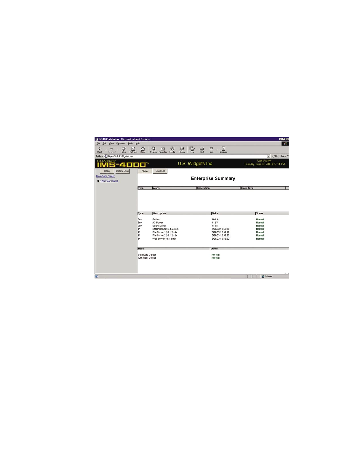
Web Page
The IMS-4000 will produce a web page which includes:
• The status of all Environmental Inputs and IP Alarms.
• The ability to program most parameters.
• Links to view logged data for each Input and IP alarm.
• Links to view historical alarm information for each Input and IP alarm.
• Graphs of the last 24 hours of logged data.
• The present state of all PowerGate outlets.
• Links to Live images from cameras.
Chapter 2: Software
Figure 49: IMS Web page
The Web Page must be enabled through the Local Configuration process via the Host’s serial port.
Optionally, the web page can also be password protected. You can program most parameters through
the web page if the Web Page Programming option is enabled. This can be secured with the same
permissions options as with the ConsoleView software. To gain access to the programming screens,
you must log in on the web page.
To view the Web Page, simply type in the Host’s IP address in your web browser.
Graphs
Anything you are data-logging, you can also graph. Graphs represent the last 24 hours of logged
data for the particular Environmental/IP element you choose to view.
To view a graph on your Web Page:
1) Select the Unit.
2) Select Environmental/IP alarms
3) Select a specific environmental or IP from the displayed list (Ex: AC Power)
4) Click the Graph button.
77
Page 78
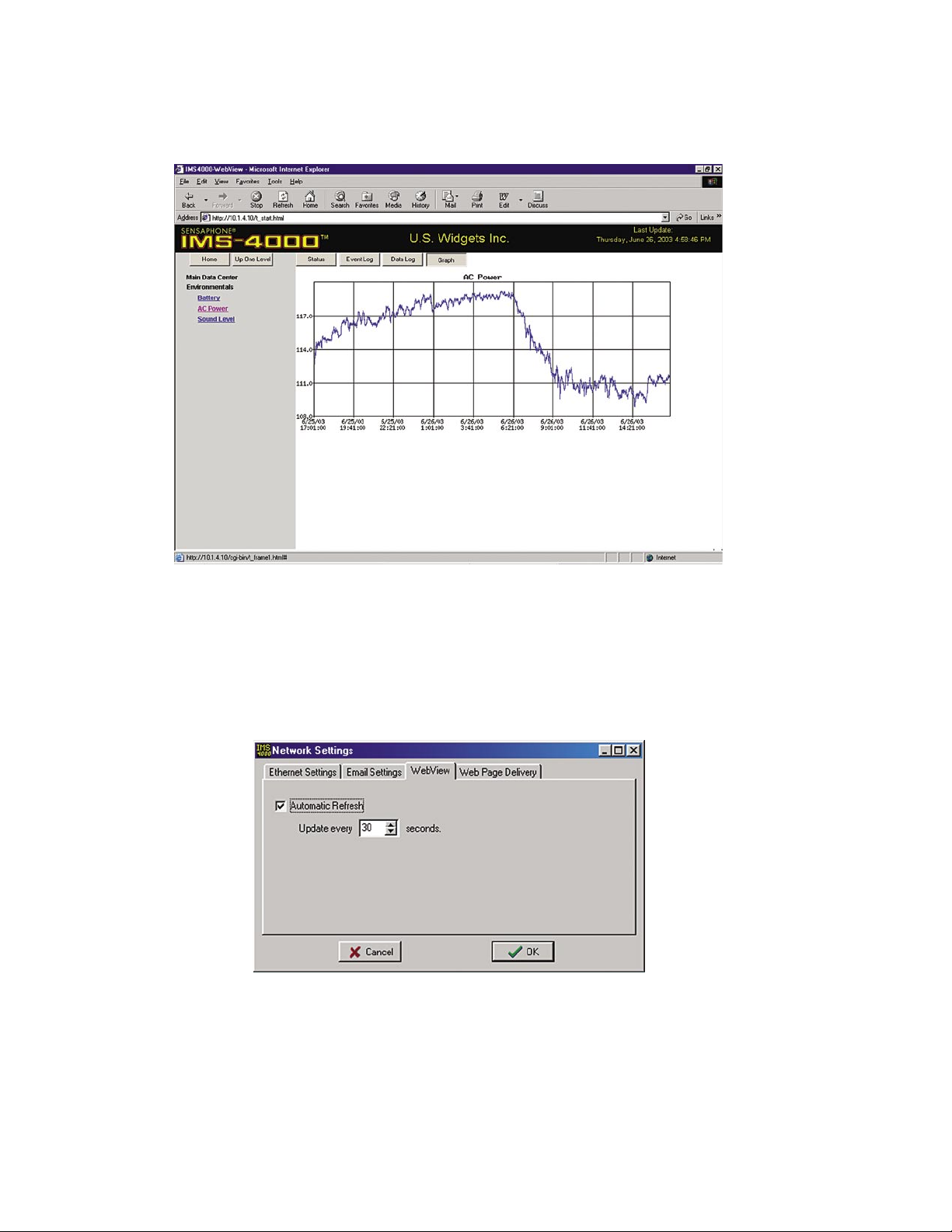
IMS-4000 Manual
The summary will be replaced by a graph for the chosen Environmental/IP item. (See following
figure.)
Figure 50: Graph of AC Power
Updating the Web Page
You can enable Automatic Updates of the data and select the interval between updates by rightclicking on the Host and selecting Network Settings. Click on the WebView tab. Check the
Automatic Refresh box and enter the number, in seconds, between updates, in the Update Every
box.
Figure 51: Web Page Refresh Enabled
Remote Web Page
The IMS-4000 can send a copy of its web page to another web server via FTP (File Transfer
Protocol), so that the web page can be viewed on another network (for example, on the Internet).
To configure the unit to FTP the web page, right-click on the Host and select Network Settings.
Next, click the tab labeled Web Page Delivery. A sample screen is shown below.
78
Page 79
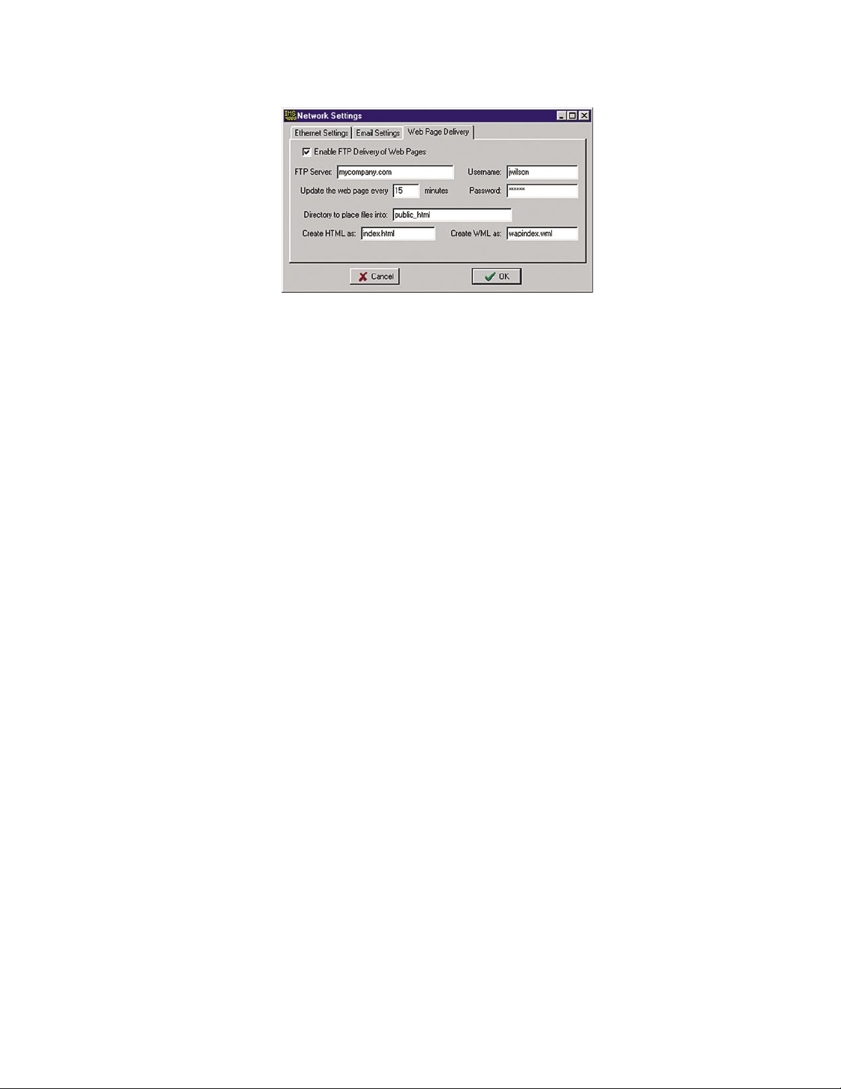
Chapter 2: Software
Figure 52: Web FTP screen
Click the Enable FTP Delivery box and fill in the necessary information for your FTP server. Your
service provider will have to provide you with the FTP Server name and sub directory where your
files will be uploaded. You will also be required to enter your username and password. You can
set how often you want the web page to be updated by entering an interval time in the Update box.
Enter a file name for the web page (e.g. ims4k.html). When you’ve finished, click OK. Listed
below are definitions of the FTP programming parameters.
FTP Server: the host name of the FTP server for your service provider.
Directory: The remote directory is the folder within the web site where the pages will upload.
Username: Your user name for your web account.
Password: The log-in password you need to access the folders and files in your web account.
Update Interval: This time period determines how often the web page is uploaded.
Create HTML as: This is the file name given to your web page.
Create WML as: This is the file name given to web pages to be viewed with wireless phones. If
no name is programmed, the unit will not ftp any wml files.
Viewing the Remote Web Page
To view the remote web page that the IMS-4000 uploaded, you need to know its web address. This
address corresponds to the Server name, plus the directory, plus the file name of the web page. It
will look something like this: http://www.mycompany.com/jwilson/ims4k.html
Note: Data Log and Event Log information are NOT available via the remote web page.
79
Page 80
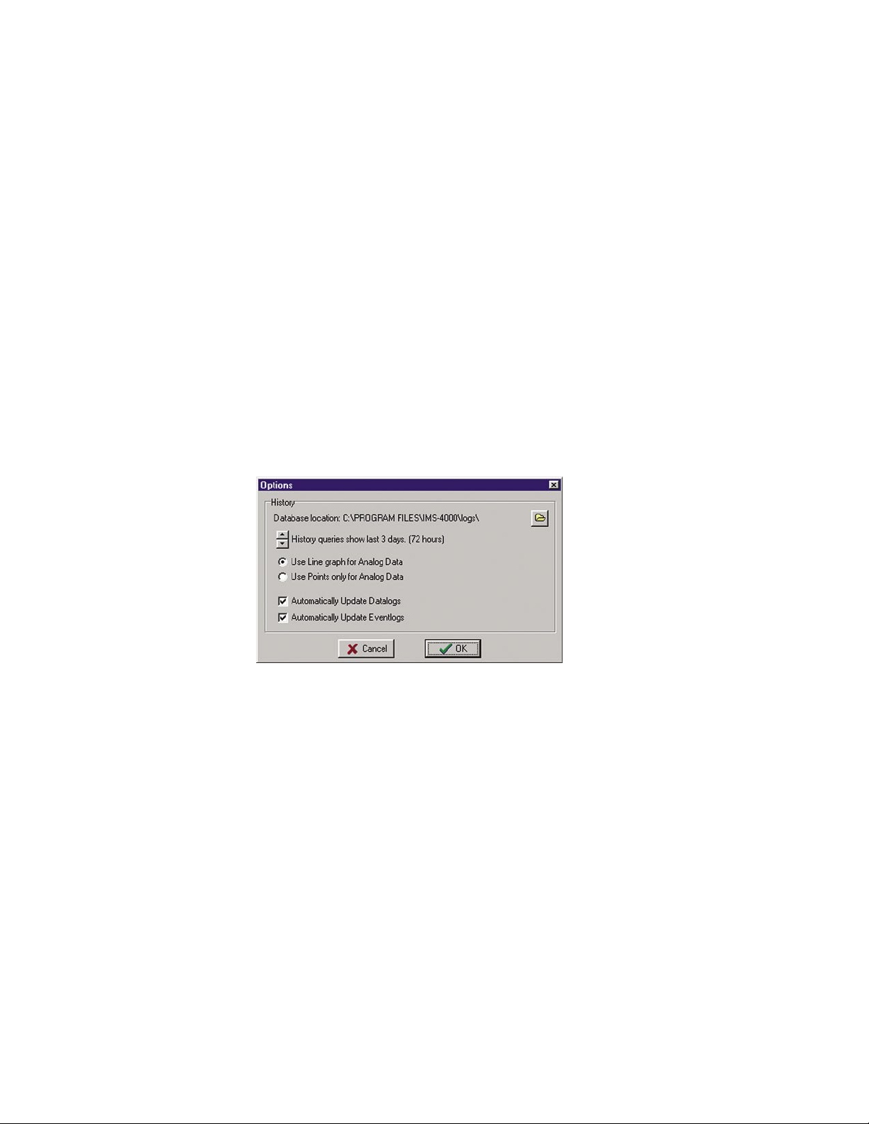
IMS-4000 Manual
History
The IMS-4000 stores both datalog and eventlog history internally. The datalog is a time-stamped
collection of input values that can be used to view and graph environmental conditions over time.
It can also store the status of IP devices. The user can choose which inputs or IP alarms are stored
and specify the overall sampling rate. Care should be taken to select the number of inputs and sam
pling rate accordingly, since large amounts of data can potentially be logged. The more data being
logged, the faster the history log will fill up.
The eventlog contains time-stamped messages that describe activities performed by the unit such as
alarm detection, user logins, telephone calls, and alarm acknowledgement. The eventlog history is
useful when you want to review the historical events monitored and performed by the IMS-4000.
When a user goes online, information for both the datalog and eventlog history is automatically
retrieved and stored in a database on a user-specified hard disk. This can be a drive on your own
computer or a network server. While the program defaults to saving the history database on your
local drive, if the system will be used by many users it may be advantageous to store the database
on a network drive. To specify the drive for saving History information click File, then Options
from the main menu. A sample screen is shown below:
-
Figure 53: History Options
To change the location for storing the History database, click the folder button on the right side of
the screen and choose a new location. The location you select will be displayed to the left.
Use the up or down buttons to select the amount of history to be viewed when accessing the
option through the right-click menus in the ConsoleView software. This provides a quick view
of the history for a particular Input or Profile. The default time is 24 hours (1 day). Clicking the
arrows will increase or decrease the data time by days.
Analog input values will automatically be graphed when viewing
menus of the ConsoleView software. You can choose to have the graphed data displayed as a line
graph or simply show the discrete data points.
You can also deselect the Automatically Update buttons if you don’t want the Datalog or Eventlog
to download each time you connect. If you are using a dialup connection, you may want to disable
these functions to speed up the software loading process. (You can manually download the logs as
desired by right-clicking on History in the menu tree.)
80
History through the right-click
History
Page 81
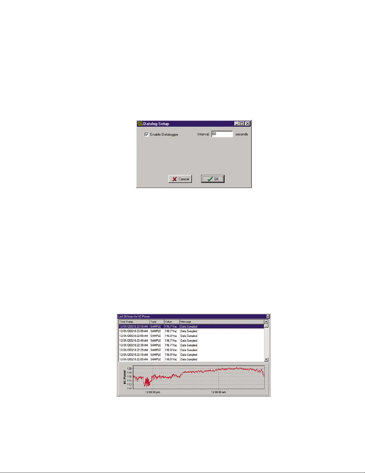
Chapter 2: Software
Datalog History
The IMS-4000 can log up to 62,500 samples of environmental and IP Alarm history. When the log
fills, it will overwrite the oldest data first. Environmental data will display the actual value, while
IP Alarm data will display either Normal, Timed Out, or IP Down. All stored history is logged at the
same interval as programmed on the History programming screen. To set up the Datalog History,
right-click on History from the IMS menu tree and select Properties. Enter the Interval time and
click the Enable box. This will start the Datalog feature. The Datalog will store Environmental and
IP Alarm values if datalogging is enabled on their respective programming screens.
Figure 54: Datalog Setup Screen
Viewing History
Datalog History can be viewed through the ConsoleView software or via the IMS web page. It can
be viewed through the ConsoleView software in two ways: There is the quick view which can be
displayed by right-clicking on an input or profile and selecting History, or you can perform a query
on the entire history database using the HistoryView program (right-click on History in the menu
tree and select HistoryView, or from the main menu select File, then HistoryView
).
History QuickView
You can display a quick view of an input or profile by simply right-clicking on the item and
selecting History. This will provide an event listing and graph of the input over the last 24 hours
(default). You can change the amount of history displayed to several hours or several days by
changing the setting on the Options screen under the File menu. A sample is shown below:
Figure 55: AC Power History
Querying the History Database with HistoryView
The HistoryView program allows you to query the entire History database for all IMS units. There
are filters to select Samples, Alarms, System messages, or User Logins. You can view data from an
IMS Host and its associated Nodes combined, or individually. You can also graph sampled data.
81
Page 82
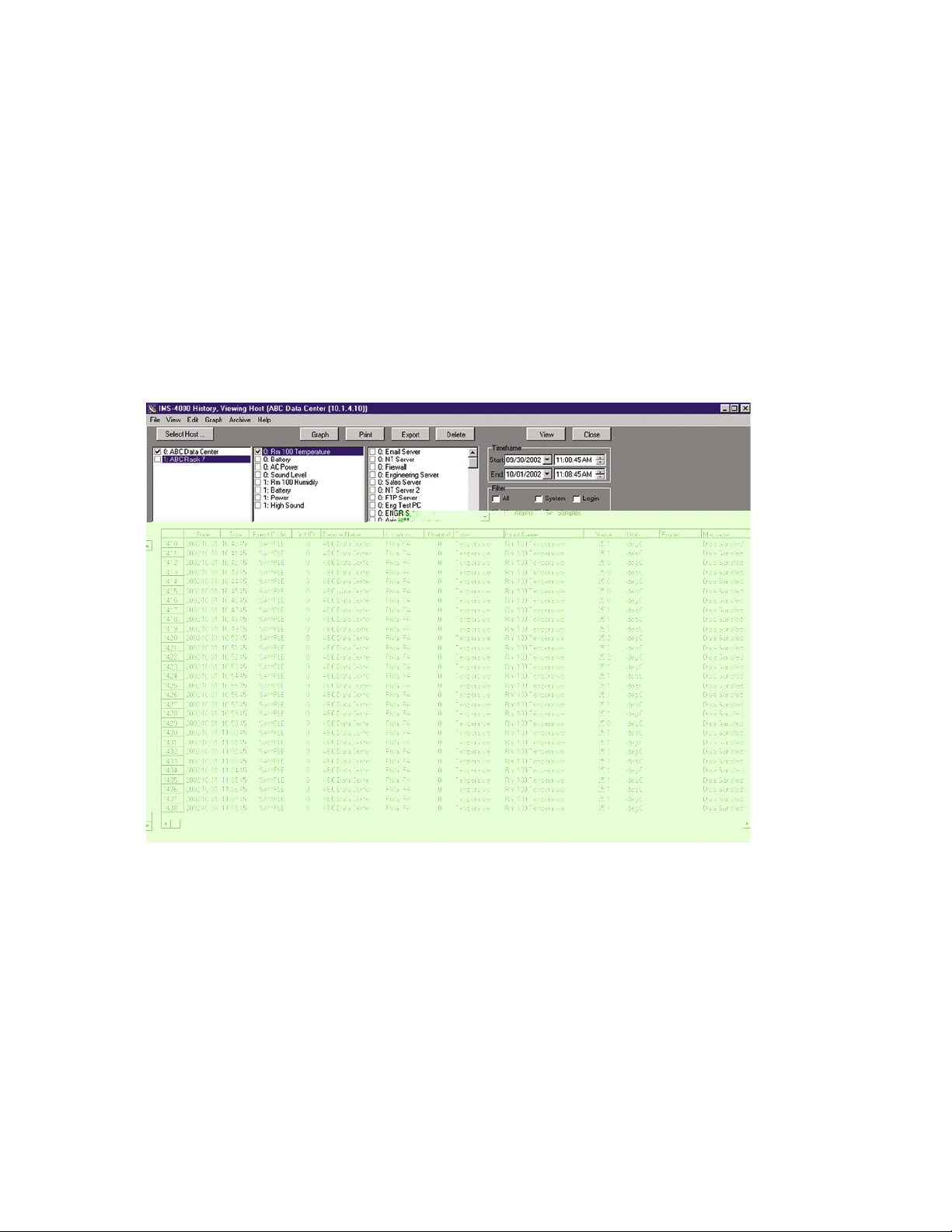
IMS-4000 Manual
To begin, run the HistoryView program by right-clicking on History in the menu tree and select
HistoryView, or from the main menu select File, then HistoryView. The first screen will prompt
you to select an IMS Host. Click in the box next the Host you want to Query. The program will
then load the associated nodes and input names. Next, select the Host or Nodes that you want to
query information on, then select any filters that you want to apply. If you select
All you will see
all events and data samples for the selected units. If you select Samples or Alarms you must then
choose one or more Environmental Inputs or IP Alarms.
Note: the number that precedes each Environmental and IP description corresponds to the unit
number to which they’re connected (0 being the Host and 1-31 being the associated Nodes).
If you double-click on an item in the Environmental or IP Alarm box, all of the listed items will
become selected and/or deselected. Last, select a time frame to perform the query and click View.
The selected data will now be displayed. See sample screen below:
Figure 56: History Viewer
Graphing
Graphing data is possible when the selected query contains only Samples.
If you click on the Graph button, all of the points in the query will be displayed as a line graph.
There are also options (from the Graph menu above) to format and display the data as a bar or area
graph. You can have up to eight items displayed on the graph at once. To view different parts of
the graph use the arrows on the bottom and sides to adjust the position. A graph can be printed by
clicking the Print button at the top of the screen. You can copy the graph to the Windows clipboard
by clicking the Copy button. This allows you to paste the graph into other applications. The Zoom
In and Zoom Out buttons let you view the data with more or less detail. The Reset button restores
the original view of the graph. When finished, click the Close button to return to the grid.
82
Page 83

Chapter 2: Software
Printing Data
You can print the data viewed in the grid by clicking the Print button. Printing defaults to an Arial
5 pt. font in order to fit one line of data across one line of an 8.5" x 11" sheet of paper printed in
landscape mode. You may choose different fonts and type sizes.
Exporting Data
The Export button allows you to save the queried data in the grid to a file format which can be
easily imported into other applications. Options include the ability to save the file in CSV format,
formatted text (prn), and tab delimited (txt) format. Note: The exported data will represent only
what you’ve selected to query.
Click on File and select Export Field Names from the submenu if you want the field titles (Date,
Time, Event Code, etc.) to be included with the data when you export.
Copying to the Clipboard
You can highlight and copy selected cells within the grid to the Windows clipboard. To highlight
the data simply click-and-hold the left mouse button and drag the mouse over the cells you wish
to highlight, then either right-click and select Copy, or click Edit from the main menu and select
Copy. To select all of the data in the grid, right-click within the grid and choose Select All from the
contextual menu, or click Edit from the main menu and choose Select All from the submenu. This
will highlight all of the data in the grid. You can then perform the Copy function as previously
described.
Deleting Data
The Delete button will remove the queried data displayed in the grid from the database.
TheViewer Menu offers you other features as well to customize your report.
Archiving
As the history database grows it will begin to take longer to perform a query. It is recommended
that the database be periodically archived to keep the size reasonable and to permit satisfactory
performance of the HistoryView program. Archiving may be done as often as necessary for perfor
mance reasons but it must be done when the database reaches its physical limit. To find out how big
the database is for a particular unit, select Database Statistics under the Archive menu. The size of
the database and percent full will appear in the status bar along the bottom of the grid. A warning
message will appear when the database reaches 80% of its capacity.
To archive the history database select Archive from the main menu and then choose Select database
to archive. Locate the history.db file for the unit you wish to archive and click
Open. Next, enter
the date range to archive (typically one or more months or a quarter). Click the Archive button. The
archived data will be stored in a file that includes the “from” and “to” date range in a yr/mn/dy format.
After archiving it’s recommended that you Pack the history database (history.db) to delete the old
data and reduce the file size. To do this select Pack Database from the Archive menu. Note that the
Pack Database function can only be executed while offline with the IMS unit. To run HistoryView
while not connected, click File, then Run from the ConsoleView main menu.
To view archived data, you will need to restore an archived database. To do this, choose Select
archive to restore from the Archive menu. Next, choose the archive file you wish to restore and
click Open. Next, click the Restore button. The archived data will be copied into the history database and a query can be performed.
83
Page 84
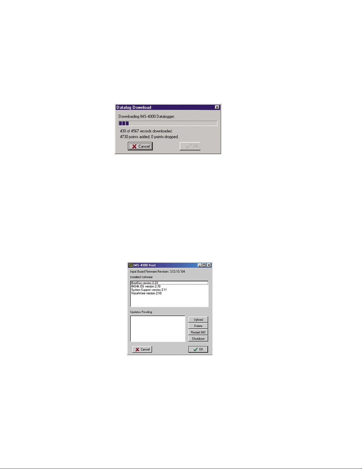
IMS-4000 Manual
Manually Forcing History Downloads
You can manually force full history downloads at any time. As previously stated, if you’re on a
dialup connection, you may choose to disable auto updates, and need to download the data periodically. To do this, go to your main IMS menu and right-click on History in the tree diagram.
Select Force Full Eventlog Download to manually download the Eventlog or Select Full Datalog
Download to manually download the current datalog.
Figure 57: A manual Datalog Download in progress
Updating Firmware
From time to time Firmware updates will become available to add features or improve the performance of your IMS-4000. Most Firmware updates will be included as part of a complete IMS4000 installation upgrade. Check the IMS-4000 website (www.sensaphone.com/support-4000.html)
for the latest information on updates. If you register your unit you will always be informed of the
latest features, enhancements, and corrections.
To check the version of Firmware in your IMS-4000, right-click on the
Version Info. The following screen will appear.
Hostname and select
Figure 58: Version Info Screen
The IMS-4000 unit firmware comprises four files: BootSys version, IMS4k OS version, System
Support version, and VoiceWare version. This screen includes functions to upload new firmware
and restart the system. Always follow the instructions included with the new firmware files prior
to installing any new versions. (Note that the Node firmware is installed separately on the Node
Diagnostics screen.)
84
Page 85
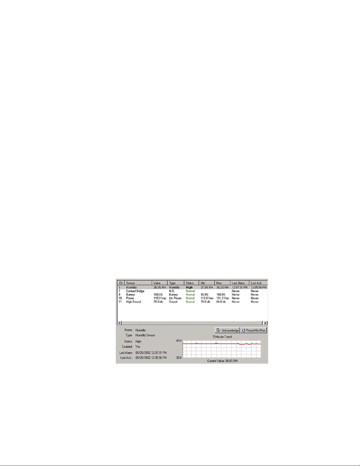
Chapter 3: Operation
Chapter 3: Operation
After installation and programming have been completed, the Sensaphone IMS-4000 is fully
operational. This chapter explains how the IMS-4000 operates.
Alarm Delivery and Acknowledgment
The IMS-4000 can be programmed to contact specific users when an alarm occurs. A user may
be contacted depending on whether the alarm has already been acknowledged by another user, or
regardless of acknowledgement by other users. This allows flexibility in configuring your system
for the way you want alarms handled. When a user does not wish to be contacted if someone else
has already acknowledged the alarm, then we call this contact type an “Until Acknowledged” con
tact. “Until Acknowledged” means that a user is on the call list until the alarm is acknowledged,
and once acknowledgement is received, this user is removed from the list. If a user always wants
to be contacted when an alarm occurs, we call this contact type “Inform Only.” This means that this
user will always receive notification of the alarm, regardless of acknowledgement by other users.
-
Alarm Acknowledgment
Alarms can be acknowledged six ways:
1) By entering your Usercode using a touch-tone telephone when prompted during a Voice
telephone call.
2) By calling in to the unit and entering your Usercode via touch-tone phone when prompted.
Only alarms that are in the User’s Class can be acknowledged. Note that the Intercall Delay
must be set to a minute or more to allow time to call in to the unit.
3) By logging-in to the IMS-4000 and clicking the Alarm Acknowledgment button on the status
screen for the Input in alarm. See sample below:
Figure 1: Alarm Acknowledgment button
4) By clicking the Ack button next to the input on the IMS web page.
85
Page 86
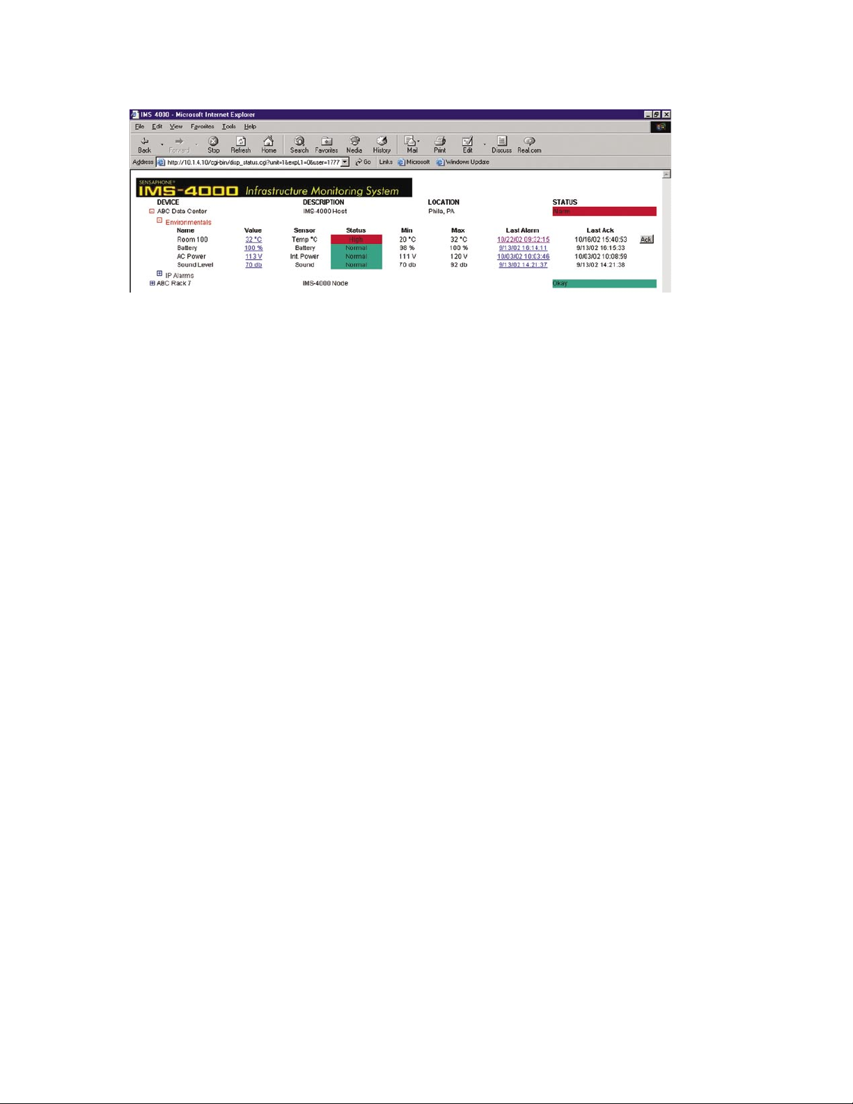
IMS-4000 Manual
5) By SNMP Management software.
6) By the IMS-4000 itself. If there are no Until Acknowledge contacts in the call list or if the
maximum number of calling rounds has been exhausted, the IMS-4000 will self-acknowledge
the alarm.
Alarm Delivery Logic
Figure 2: Web page acknowledgment
When an alarm occurs, the IMS-4000 will check for Class matches between the input or IP alarm
and the User Profiles. When matches are found, the IMS-4000 will then check to see if the associated User Profile is enabled and then check the schedule of each of the Contacts for the profile. Those Contacts that are active at the time will then be called depending on whether they
are enabled to receive Inform Only calls or receive Unacknowledged Alarm calls or both. Those
contacts enabled for Inform Only will always receive the alarm message, regardless of whether the
alarm has been acknowledged or the input or IP alarm returns to Normal. Contacts set to receive
Unacknowledged Alarms will only receive calls if the alarm has not been acknowledged. Note that
alarms can only be acknowledged during a voice call or by logging in via the IMS Consoleview
Software. If there are NO calls of the Unacknowledged type, then the IMS-4000 will acknowl
edge the alarm immediately after starting the alarm delivery process. It is not recommended that
you set pager calls to Unacknowledged unless there are also voice calls being made, the reason
being that the only method of acknowledgment in this case will be to log in to the unit via the IMS
Consoleview software. Voice Contacts that are enabled for both Inform Only and Unacknowledged
will always receive the alarm message, but in addition will have the opportunity to acknowledge
alarms by entering their Usercode via touch-tones (if the alarm hasn’t already been acknowledged).
As long as an alarm remains unacknowledged AND it has Unacknowledged Contacts to be called,
the IMS-4000 will continue to call these contacts until an acknowledgment is received OR the max
imum dial attempts is reached. Alarms are acknowledged during a voice call by entering the User
Code when prompted.
-
Sample Alarm Messages
Sample E-mail alarm message
Subject: IMS-4000 Alarm
FROM: ABC Widgets Inc.
IMS-4000 Host
Boston, MA
86
Page 87

Chapter 3: Operation
ALARM MESSAGE:
High temperature ALARM at ABC Widgets Inc.
CH1: Server room temperature is now 90.3 Deg F
Level crossed limit of 85.0 Deg F
on Thursday 28 March 2002, 10:24:32 AM EST
Sample Fax message
***************** IMS-4000 ALARM REPORT *****************
TO: John Smith
CIO
ABC Widgets Inc.
Information Technology
FAX NUMBER: 7779992233
FROM: ABC Widgets Inc.
IMS-4000 Host
Boston, MA
PHONE NUMBER: 7779992000
ALARM MESSAGE:
High temperature ALARM at ABC Widgets Inc.
CH1: Server room temperature is now 90.3 Deg F
Level crossed limit of 85.0 Deg F
on Thursday 28 March 2002, 10:24:32 AM EST
Sample Alphanumeric Pager Message
*IMS4000 ALARM* High temperature ALARM at ABC Widgets
Inc. CH 1: Server room temperature is now 90.3 Deg F
on Thursday 28 March 2002, 10:24:32 AM EST
Voice Status Report and Touch-Tone Commands
The IMS-4000 is capable of delivering a spoken status report when called via telephone. The status
report can provide information on both environmental conditions and IP alarms. In addition, you
can ping devices over the telephone and switch PowerGate outlets.
User Specific Reports
The status report is customized based on your User Code. Only callers with a valid User Code can
hear a Status Report. Alternatively, the unit is also capable of matching the calling number to one of
the Contact Numbers, using Caller-ID (if available). When the unit receives Caller-ID information
it searches all of the Contact Numbers to try to find a match to a particular user. If a match is found
the unit customizes the report based on the User Profile
The unit creates a custom report based on the Classes that the User has selected. Only inputs for
which there is a Class match between the user Class List and the input Alarm Class will be report
ed. For example, if a user had selected temperature and humidity in their User Class List, then only
inputs with Alarm Class temperature and humidity will be reported.
.
-
87
Page 88

IMS-4000 Manual
Sample Status Report
To receive a status report, call the unit. When it answers wait for the beep. Immediately after hearing the beep, press any touch-tone. The unit will begin speaking and request your User Code. If the
unit receives a valid User Code it will continue with several menu options. A sample of the main
menu is shown below:
“Hello, this is the IMS-4000 at the IT Dept of XYZ Company
“Enter your user code:”
To hear the environmental status, press
To hear the IP status, press
To ping an IP device press
To check the status of a PowerGate outlet, press
To switch an outlet on a PowerGate, press
To turn on the microphone, press
To disconnect, press
To repeat this menu, press
If the caller had selected option 1 they would get a sub-menu asking if they would like to hear an
environmental alarm summary report or a full environmental status report. The alarm summary
only reports on inputs that are currently beyond their limits, or are in an alarm condition and have
a class match. The full report provides status on all inputs that have a class match. A sample of a
full environmental status report is listed below. Items in italics are custom messages recorded by the
user.
Environmental sensors at the IT Dept of XYZ Company
Channel 1, temperature in the server room, is 76.4 degrees Fahrenheit, OK
Channel 2, temperature in rack B, is 82.7 degrees Fahrenheit, too high
Channel 3, humidity in the server room, is 33.9%, OK
Channel 6, water under server room floor, OK
Channel 7, smoke alarm in the server room, OK
Channel 9, battery, is 100.0%, OK
Channel 10, power, is 116.3 volts, OK
Channel 11, Sound level, OK
7.
2.
3.
8.
1.
4.
5.
6.
Note: The Voice menus are intelligent, such that they will only recite menu options if there is
relevant content. For example, if there are no IP Alarms programmed then the IP Alarm menu
option will be skipped, or if there is no PowerGate connected, then this menu option will be
skipped; or if the User has no Environmental sensors in his class, then these will be skipped.
Voice Alarm Dialout
The IMS-4000 can call and deliver an alarm message in spoken English. After dialing, the unit
will begin speaking “IMS-4000 Alarm Message, Press any key to continue.” If the unit receives a
touch-tone, it will recite the alarm message. When it finishes speaking the message it will request
acknowledgement (if the call type is Until Acknowledged; if the call type is Inform, the unit will
just speak the alarm message and disconnect). A sample Voice Alarm call is shown below:
88
Page 89

Chapter 3: Operation
“IMS-4000 Alarm Message, press any key to continue”
“IMS-4000 Alarm Message, press any key to continue” {call is answered and a 5 is pressed}
“IMS-4000 Alarm Message. The temperature is High at the IT Dept of XYZ Company.”
“Channel 1, temperature in the server room, is 81.5 Degrees Fahrenheit”
“Level exceeded limit of 80 Degrees Fahrenheit at 7:45PM.”
“Enter User Code:” {valid User Code is received}
“Alarm Acknowledged. Goodbye.”
Performing an IP Ping via Telephone
The IMS-4000 allows you to perform an IP Ping during a voice call-in to the Host. After dialing
the unit, press a touch-tone after the beep. The unit will request your User Code. Next, listen to
the menu choices. Option 3 will allow you to enter an IP address in numeric dot-quad format. Use
the * key for a dot. A sample IP Ping is shown below:
“Hello this is the IMS-4000 at the IT Dept of XYZ Company.”
“Enter your User Code:” {valid User Code is received}
“To hear the environmental status, press
“To hear the IP status, press
“To ping an IP device press
“Enter IP address, Use the star key for dot. Press pound (
{user enters 10.1.4.17}
“Pinging now...”
“10.1.4.17 is not responding”
2.”
3.” {3 is received}
1.”
#) when finished.”
Call-in Alarm Acknowledgment
If you receive an alarm message on your pager or in your voice mail, you can still acknowledge the
alarm by calling the unit back and entering your User Code. Note that the Intercall Delay must be
set to at least 1 minute in order for the unit to answer a call.
When you call in to the unit, wait for the beep and then press a button on your touch-tone telephone. If there are unacknowledged alarms in the User’s class, the unit will say “Unacknowledged
alarms exist. To hear the alarms, press 9.” If you press 9, the IMS will announce all unacknowl
edged alarms that are in the User’s class. When the unit finishes announcing all of the alarms,
it will say “Enter your user code.” If the user code is entered correctly the unit will say “Alarm
acknowledged” and it will acknowledge all of the alarms announced, and stop dialing all contacts
programmed as “Until Acknowledged” type.
Remote Login via Dialup
You can remotely connect to the IMS-4000 via modem using Windows Dial-up Networking. This
is a standard utility included with the Windows operating system. Follow the instructions below
according to your installed operating system to set up Dial-up Networking.
Windows 95 and 98
To configure Dial-up Networking, double-click on My Computer from the desktop or click the Start
button and select Programs>Accessories>Communications>Dialup Networking. Click on Make
New Connection. Follow the prompts to configure this connection. You will need to enter a name
-
89
Page 90

IMS-4000 Manual
(“IMS-4000,” for example), choose your modem, and enter the telephone number of your IMS-
4000. When you’re finished, an icon should appear with the name you provided. Double-click on
this icon. Enter a Username and Password which matches a Profile Username and Password in
your IMS-4000. Click Connect to have your modem dial up your IMS-4000.
Note: If Dialup Networking is not listed it may not be installed on your computer, in which case
you will need to use your Windows installation CD to add it.
Windows 2000
To configure Dial-up Networking, double-click on My Computer from the desktop or click the Start
button and select Settings>Control Panel. Double-click on the icon called Network and Dialup
Connections. Double-click on Make New Connection. Follow the prompts to create a new connection. For the Network Connection Type choose Dial-up to Private Network. Enter the telephone
number of your IMS unit and assign a name to the connection (“IMS-4000,” for example). When
prompted to enter your Username and Password be sure to enter information which matches a
Profile Username and Password in your IMS-4000.
Note: If Dialup Networking is not listed it may not be installed on your computer, in which case
you will need to use your Windows installation CD to add it.
Windows XP
To configure Dial-up Networking, double-click on My Computer, then select My Network Places,
then View Network Connections. Select Create a New Connection or click on the Start button, then
Programs>Accessories>Communications>New Connection Wizard. Follow the prompts to create
a new connection. On the Network Connection Type screen, select Connect to the Network at my
Workplace. For the network connection choose Dial-up. Enter a name for the connection (“IMS-
4000,” for example) and the IMS-4000 telephone number when prompted. Finish the setup. When
prompted to enter your Username and Password be sure to enter information which matches a
Profile Username and Password in your IMS-4000.
Communicating with your IMS-4000
Double-click on the Dial-up Networking icon you just created above. This should make your
computer dial your IMS-4000 and connect. Once a connection is established, run the IMS-4000
ConsoleView Software by double-clicking on the IMS-4000 icon on your desktop. At this point you
should be communicating with your IMS-4000. To disconnect, close the IMS-4000 Software and
then disconnect the Dial-up Networking connect
90
Page 91

Chapter 4: SNMP
Chapter 4: SNMP (Simple Network Management Protocol)
The IMS-4000 Host contains an SNMP agent that supports all three current versions of SNMP (v1,
V2c, and V3), over both UDP and TCP transports. Read and write access to most of the IMS-4000
parameters is provided along with the ability to send traps when alarms occur. A complete SNMPv1
MIB is provided on the IMS-4000 CD.
The SNMP agent can be enabled or disabled from the local configuration options while directly con
nected to the IMS-4000 via RS-232. The SNMP community strings are also configured through the
local configuration. See Chapter 1 for details.
Through the SNMP protocol, most of the programming parameters and status information can be
accessed. The following is a summary of the IMS-4000 items that can be fully accessed through
SNMP:
= Edit Environmental input programming
= Edit IP Alarm programming
= Edit System programming (unit info, e-mail setup, Web FTP setup, phone settings)
= Enable/Disable Datalogging
= Edit the Datalog interval
= Edit/add Classes
= Edit Environmental input template programming
= Edit Camera setup
= Edit PowerGate programming and switch outlets
= Acknowledge alarms
= View Network and Security configuration parameters
= View system diagnostic information
-
Some parameters of the IMS-4000 involve complex data structures and cannot be accessed through the
SNMP protocol. The following operations
= Add or delete IP alarms
= Add or delete Profiles or Contacts
= Delete a sensor
= Delete a Node
= Delete a PowerGate device
= Configure the system clock
= Modify time schedules
= Edit alarm response programming sequences
= Modify classes on Environmental Inputs, IP Alarms, or Profiles
cannot be performed through SNMP:
91
Page 92

IMS-4000 Host Installation Manual
The various values that can be retrieved from an MIB are called MIB variables. Each MIB variable is
named by an Object Identifier (OID), which usually has a name in the form of numbers separated by
periods (“.”), like this: .1.3.6.1.x.x.xxxx.x.x.x.x... OIDs for all MIB variables can be determined by
browsing the MIB.
Below are some examples of the more common OIDs in the IMS-4000:
Name: .iso.org.dod.internet.private.enterprises.sensaphone
Sensaphone OID: .1.3.6.1.4.1.8338
Host Environmental Input Values: .1.3.6.1.4.1.8338.1.1.1.1.8.1.1.7.(input number)
Example: host environmental input #3: .1.3.6.1.4.1.8338.1.1.1.1.8.1.1.7.3
Node Environmental Input Values: .1.3.6.1.4.1.8338.1.1.1.(N+1).8.1.1.7.(input number)
{where N is the node number.}
Example: node 5, environmental input #6: .1.3.6.1.4.1.8338.1.1.1.6.8.1.1.7.6
92
Page 93
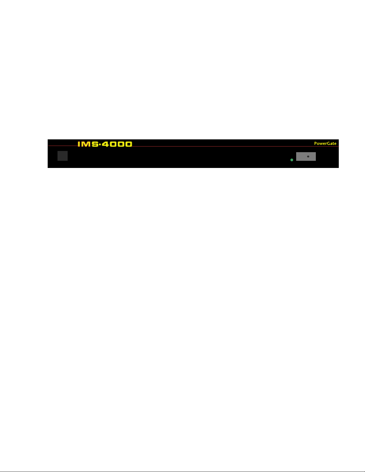
Chapter 5: PowerGate
Chapter 5: PowerGate
Physical Description
The IMS-4000 PowerGate is housed in a 17"w x 1.75"h x 10"d enclosure, which is 1 EIA rackmount space high.
Front Panel Layout
The front panel contains a 15 Amp breaker, Output LEDs, the serial port and power indicator. See
figure below:
Page 94

IMS-4000 Manual
Parts Required
Phillips 9 pin F/F null
Screwdriver modem cable
Operating Environment
Before you install the IMS-4301 PowerGate be sure that your operating environment meets the
physical requirements of the equipment.
Operating Temperature: 32º –122º Fahrenheit (0º– 50º C)
Humidity: 5– 90 %RH, non-condensing
Power: 120VAC 60 Hz outlet within 6'
Rack Requirements: Standard 19' equipment rack with supplied mounting bracket
hardware. Requires 1.0 EIA rack mount space.
Tabletop requirements: Flat area which can support an enclosure 17" wide by 10" deep by 2"
high.
Rack Mount Installation
The IMS-4301 PowerGate can be rack mounted using the included rack mount brackets. Follow the
steps below:
1) Attach the rack-mount brackets to the PowerGate with a Phillips screwdriver.
2) Attach the unit to the equipment rack using two pan-head screws per side. Tighten the
screws with a Phillips screwdriver.
3) Plug the power cord into a 120VAC outlet.
94
Page 95
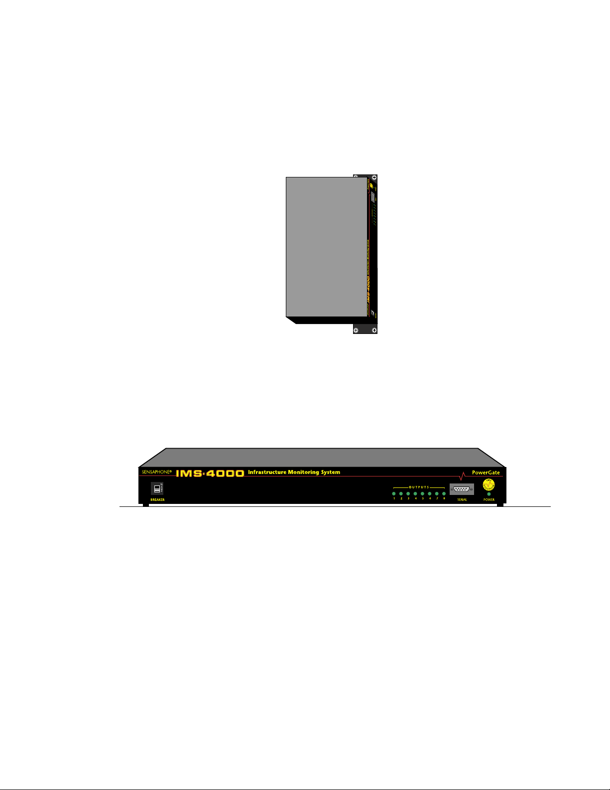
Chapter 5: PowerGate
1) Attach the optional wall mount brackets to the sides of the IMS-4301 using the eight black
#6-32 screws. A Phillips screwdriver will be required. (Order part # IMS-4501 Universal
Wall Mount Kit)
2) Attach the unit to the wall using two screws per side. Tighten the screws with a Phillips
screwdriver.
3) Plug the power cord into a 120VAC outlet.
Figure 4: Wall-mounted PowerGate Unit
Tabletop Installation
The IMS-4301 PowerGate can be installed on a tabletop or shelf. Follow the steps below:
1) Attach the four self-adhesive rubber feet to the four corners on the bottom of the IMS-4301.
2) Place the unit on a tabletop or shelf and connect the power cord into a 120VAC outlet.
Figure 5: Tabletop-mounted PowerGate Unit
Connection to IMS-4000 Host or Node
The PowerGate connects to an IMS-4000 Host or Node using the 9-pin null modem cable (included). Connect the cable to the RS-232 port on the PowerGate and connect the other end to the RS232 port on the Host or Node. The PowerGate will automatically be recognized by the system and
appear in the IMS-4000 ConsoleView software.
Operation
Plugging In Equipment
Attach the power cord from each device to be switched into one of the outlets on the back of the
PowerGate. Be sure to support heavy cables with tie wraps or some other method to prevent the
unit from bending down (See the figure below). Too much weight in the rear may cause permanent
damage to the enclosure.
95
Page 96
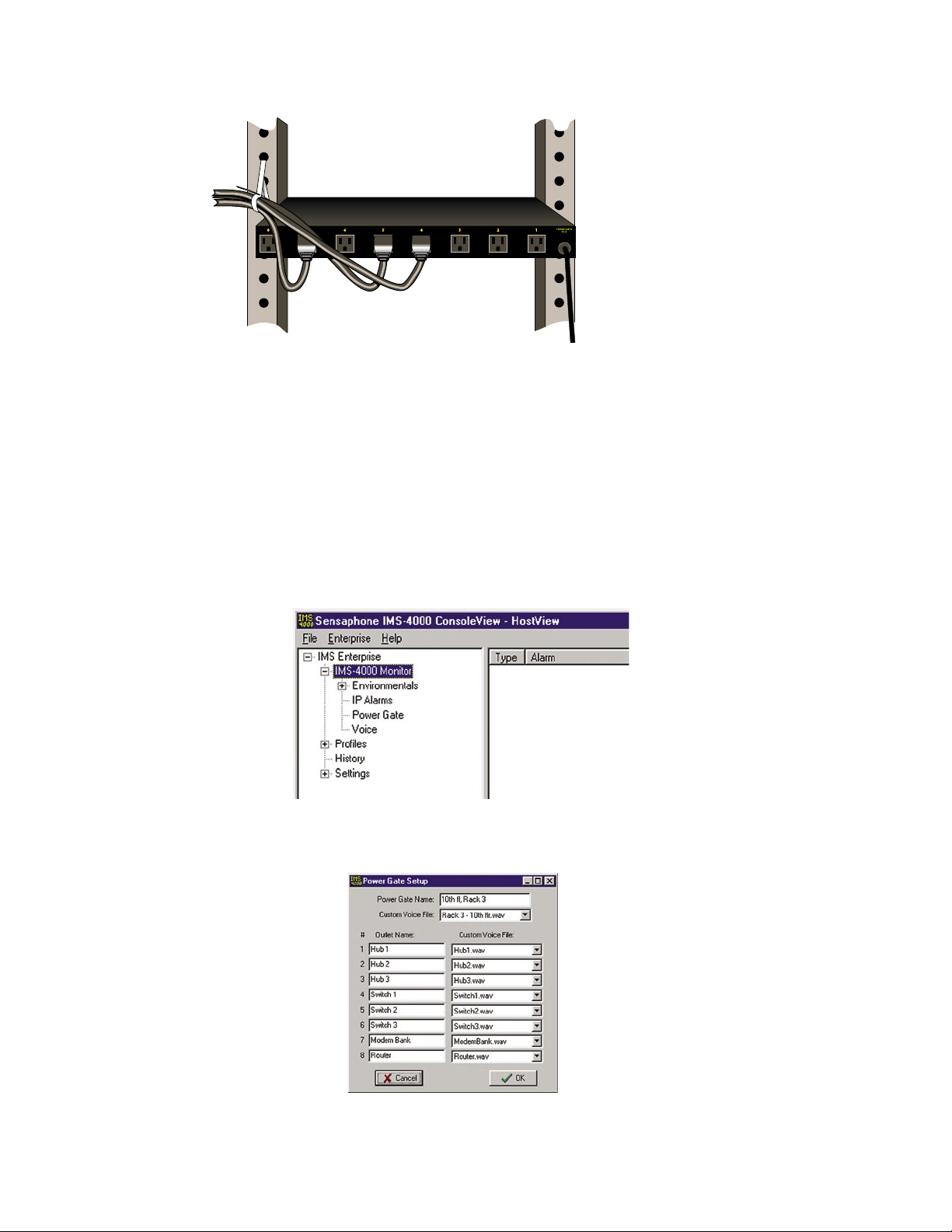
IMS-4000 Manual
Figure 6: Cable Support
Each outlet provides 115VAC 60Hz. To ensure that the maximum power will be available, be sure
to plug the PowerGate itself into a circuit which can supply at least 15 Amps. The total of all devices connected to the PowerGate cannot exceed 15Amps.
PowerGate Setup via the IMS ConsoleView Software
The PowerGate will automatically be recognized by the IMS Host or Node. Within the IMS tree
structure an entry called PowerGate will appear within the submenu of the Host and/or Node. To
expand the Host or Node submenus you must click the box with the plus sign next to the appropriate Host or Node. The figure below shows the menu location of a PowerGate connected to a Host.
Figure 7: PowerGate in Hierarchy
To assign labels to the PowerGate, right-click on PowerGate. The following screen will appear:
96
Figure 8:PowerGate Setup
Page 97
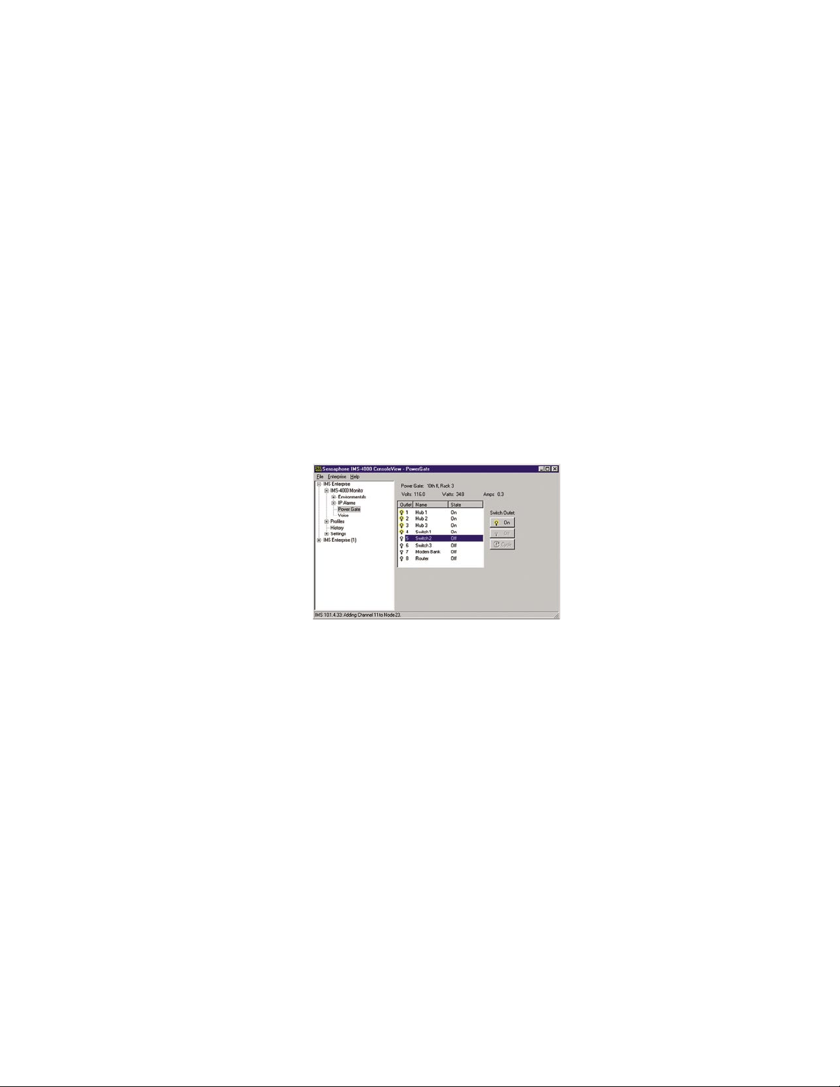
Chapter 5: PowerGate
Assign a name to the PowerGate that describes its location. Also, assign labels to each outlet which
describes the device plugged into that outlet. This information will be critical when it comes time
to reboot a device. You can also assign voice messages to the PowerGate and each outlet. The voice
messages will allow you to control equipment via telephone using touch-tones. Use the Voice
Message programming screen to record your messages.
Switching Outlets using the IMS ConsoleView Software
To switch an outlet from the IMS ConsoleView Software, left-click on the word PowerGate within
the menu tree. The screen below will appear. Click on the “name” or number of the outlet(s) you
wish to switch. In the figure, outlet 5 is selected. Multiple outlets can be switched at the same
time by holding down either the Shift key (to select a continuous block) or the Control Key (to
select a discontinuous assortment of outlets). After making your selections, click the On
Cycle button to execute the command. When Cycle is selected, the outlet will be switched Off for
10 seconds and then will automatically switch back On. When you select Off or Cycle, an additional prompt appears to confirm that you really want to remove power from the selected device.
Note that the PowerGate will switch each outlet after a short delay, but the PowerGate2 will switch
all selected outlets simultaneously.
, Off or
Figure 9: Switching Outlets
Automatic Outlet Switching
The IMS-4000 allows you to program an Alarm Response whenever an environmental or IP
Alarm occurs. An Alarm Response is an action that occurs automatically whenever an alarm
occurs. Using the PowerGate you can automatically turn On, Off, or Cycle equipment whenever
an Environmental or IP alarm occurs. See Configuring Environmental Inputs and Configuring IP
Alarms in the IMS-4000 Software Configuration Manual for details.
Switching Outlets via Telephone
The IMS-4000 allows you to switch PowerGate outlets using a touch-tone telephone. To do this
simply call the unit and enter the voice menu system. You must have a valid user code and the
appropriate permissions to execute this command.
Switching Outlets via Email
See the Two-Way E-Mail Commands section in the Software Configuration manual.
97
Page 98

IMS-4000 Manual
IMS PowerGate Specifications
Operating Specifications
Temperature
Humidity
Power Supply
Current Consumption
Over-Current Protection
Dimensions
32–122° F
5–90% RH non-condensing
120VAC 60Hz
100mA + output load
15A Breaker
1.8"h x 10.0"d x 17.3"w
98
Page 99
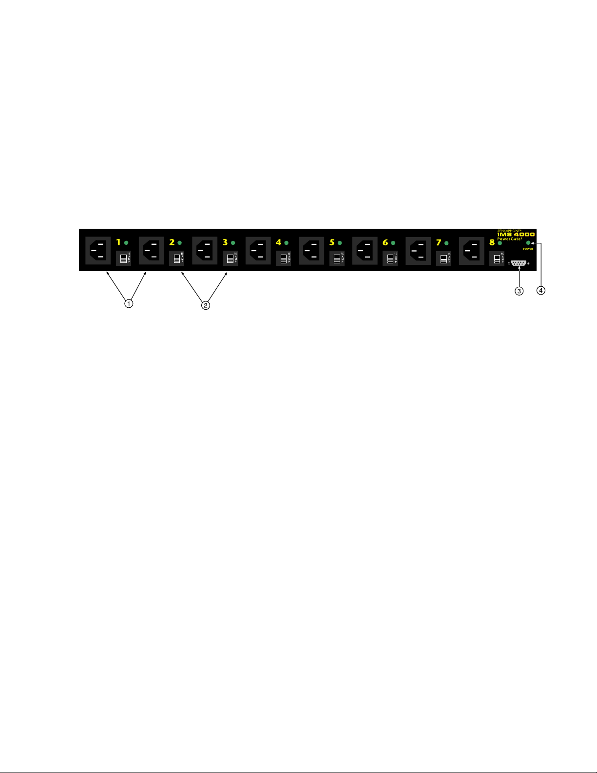
Chapter 6: PowerGate2
Chapter 6: PowerGate2
Physical Description
The IMS-4000 PowerGate2 is housed in a 17.5"w x 1.75"h x 12.3"d enclosure, which is 1 EIA
rack-mount space high.
Front Panel Layout
The front panel contains eight power inputs corresponding to the eight outlets on the rear, eight 15
Amp breakers, power LEDs, a serial port and one power indicator LED. See figure below:
Page 100
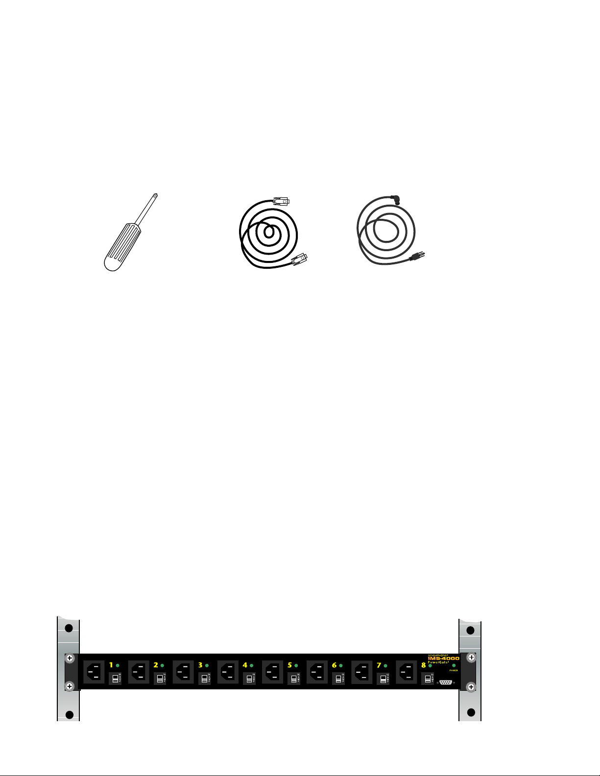
IMS-4000 Manual
Installation
This section provides information on:
n Operating environment
n Rack, wall, and tabletop installation
Parts Required
Phillips 9 pin F/F null Right-angle input
Screwdriver modem cable power cable (1 included)*
*For additional right-angle power input cables, order part # IMS-4413.
Operating Environment
Before you install the IMS-4302 PowerGate2 be sure that your operating environment meets the
physical requirements of the equipment.
Operating Temperature: 32º –122º Fahrenheit (0º– 50º C)
Humidity: 5– 90 %RH, non-condensing
Power: 120VAC 60 Hz outlet within 6'
Multiple 15A 120VAC outlets for powering equipment
Rack Requirements: Standard 19' equipment rack with supplied mounting bracket
hardware. Requires 1.0 EIA rack mount space.
Tabletop requirements: Flat area which can support an enclosure 17" wide by 10" deep by 2"
high.
Rack Mount Installation
The IMS-4302 PowerGate2 can be rack mounted using the included rack mount brackets. Follow
the steps below:
1) Attach the rack-mount brackets to the PowerGate2 with a Phillips screwdriver.
2) Attach the unit to the equipment rack using two pan-head screws per side. Tighten the
screws with a Phillips screwdriver.
100
3) Plug the power cord into a 120VAC outlet.
Figure 3: Rack-mounted PowerGate2 Unit
 Loading...