

Page 1

User’s Manual
version 2.02
Phonetics, Inc.
i
Page 2

Data Remote User’s Manual
Every effort has been made to ensure that the information in this document is
complete, accurate and up-to-date. Phonetics, Inc. assumes no responsibility
for the results of errors beyond its control. Phonetics, Inc. also cannot
guarantee that changes in equipment made by other manufacturers, and
referred to in this manual, will not affect the applicability of the information
in this manual.
Patent Pending
© 1996 by Phonetics, Inc.
Second Edition, version 2.02, September, 2000
Written and produced by Phonetics, Inc.
Please address comments on this publication to :
Phonetics, Inc.
901 Tryens Road
Aston, PA 19014
www.sensaphone.com
Data Remote™ is a trademark of Phonetics, Inc.
Touch-Tone™ is a trademark of AT&T.
ii
Page 3

Safety Instructions
Your Data Remote has been carefully designed to give you years of safe,
reliable performance. As with all electrical equipment, however, there are a
few basic precautions you should take to avoid hurting yourself or damaging
the unit:
• Read the installation and operating instructions in this manual
carefully. Be sure to save it for future reference.
• Read and follow all warning and instruction labels on the product
itself.
• To protect the Data Remote from overheating, make sure all openings
on the unit are not blocked. Do not place on or near a heat source,
such as a radiator or heat register.
• Do not allow your Data Remote to get wet, or spill liquid of any kind
into it.
• Be certain that your power source matches the rating listed on the AC
power transformer. If you’re not sure of the type of power supply to
your facility, consult your dealer or local power company.
• Do not allow anything to rest on the power cord. Do not locate this
product where the cord will be abused by persons walking on it.
• Do not overload wall outlets and extension cords, as this can result in
the risk of fire or electric shock.
• Never push objects of any kind into this product through ventilation
holes as they may touch dangerous voltage points or short out parts
that could result in a risk of fire or electric shock.
• To reduce the risk of electric shock, do not disassemble this product,
but return it to Phonetics’ Customer Service, or another approved
repair facility, when any service or repair work is required. Opening or
removing covers may expose you to dangerous voltages or other risks.
Incorrect reassembly can cause electric shock when the unit is
subsequently used.
If anything happens that indicates that your Data Remote is not working
properly or has been damaged, unplug it immediately and follow the
procedures in the manual for having it serviced. Return the unit for servicing
under the following conditions:
1. The power cord or plug is frayed or damaged.
2. Liquid has been spilled into the product or it has been exposed to
water.
iii
Page 4

Data Remote User’s Manual
3. The unit has been dropped, or the enclosure is damaged.
4. The unit doesn’t function normally when you’re following the
operating instructions.
Avoid using a telephone (other than a cordless type) during an electrical storm.
There may be a remote risk of electric shock from lightning. Do not use the
telephone to report a gas leak in the vicinity of the leak.
FCC Requirements
Part 68: The Data Remote complies with Part 68 of the FCC rules. On the
back of the unit there is a label that contains, among other information, the
FCC Registration Number and the Ringer Equivalence Number (REN) for
this equipment. You must, upon request, provide this information to your
local telephone company. The REN is useful to determine the quantity of
devices that you may connect to your telephone line and still have all of those
devices ring when your telephone number is called. In most, but not all areas,
the sum of the REN’s of all devices connected to one line should not exceed
five (5.0). To be certain of the number of devices that you may connect to
your line, you may want to contact your local telephone company to
determine the maximum REN for your calling area.
This equipment may not be used on coin service provided by the telephone
company. Connection to party lines is subject to state tariffs.
Should the Data Remote cause harm to the telephone network, the telephone
company may discontinue your service temporarily. If possible, they will
notify you in advance. But if advance notice isn’t practical, the telephone
company may temporarily discontinue service without notice and you will be
notified as soon as possible. You will be informed of your right to file a
complaint with the FCC. The telephone company may make changes in its
facilities, equipment, operations, or procedures where such action is reasonably
required in the operation of its business and is not inconsistent with the rules
and regulations of the FCC that could affect the proper functioning of your
equipment. If they do, you will be notified in advance to give you an
opportunity to maintain uninterrupted telephone service.
If you experience trouble with this equipment, or you need information on
obtaining service or repairs, please contact:
The telephone company may ask that you disconnect this equipment from the
network until the problem has been corrected or until you are sure that the
equipment is not malfunctioning.
Phonetics, Inc.
901 Tryens Road, Aston, PA 19014
(610) 558-2700 Fax: (610) 558-0222
iv
Page 5

Part 15: This equipment has been tested and found to comply with the limits
for a Class A digital device, pursuant to Part 15 of the FCC Rules. These
limits are designed to provide reasonable protection against harmful interference when the equipment is operated in a commercial environment. This
equipment generates, uses and can radiate radio frequency energy and, if not
installed and used in accordance with the instructions, may cause harmful
interference to radio communications. Operation of this equipment in a
residential area is likely to cause harmful interference in which case the user
will be required to correct the interference at his own expense.
Telephone Consumer Protection Act
The FCC Telephone Consumer Protection Act of 1991 makes it unlawful for
any person to use a computer or other electronic device, including FAX
machines, to send a message unless such message contains, in a margin at the
top or bottom of each transmitted page or on the first page of the transmission, the date and time it is sent and an identification of the business or other
entity, or other individual sending the message, and the telephone number of
the sending machine or such business, other entity, or individual. (The
telephone number provided may not be a 900 number or any other number
for which charges exceed local or long-distance transmission charges.)
To comply with this law, you must enter the following information into your
Data Remote:
• Date & Time as shown in Chapter 4: Programming. See “Clock”
section.
• Name and telephone number to identify the source of the FAX
transmission as shown in Chapter 4: Programming. See “Cover”
section.
v
Page 6

Data Remote User’s Manual
vi
Page 7

Contents
version 2.02
9-00
Safety Instructions .................................................. iii
FCC Requirements .................................................................... iv
Telephone Consumer Protection Act ....................................... v
Chapter 1: Introduction ........................................ 11
Reporting Capabilities ............................................................. 11
Alarm Functions....................................................................... 11
Remote Access ......................................................................... 12
Technical Support................................................................... 12
Chapter 2: Installation ........................................... 13
Operating Environment .......................................................... 13
Mounting .................................................................................. 13
Power and Telephone Line...................................................... 14
Power Surge Protection .......................................................... 14
Connecting Data Remote to Your Device.............................. 14
Chapter 3: Communications Setup ...................... 15
Using HyperTerminal in Windows 95 to Communicate Locally .....15
Using HyperTerminal...to Communicate Remotely via Modem ..... 16
Using Microsoft Windows 3.1 “Terminal”........................................17
Local Communication through Programming Port .............. 17
Remote Communication ......................................................... 18
RS232 Specifications ............................................................... 19
Programming Port........................................................................... 19
Data In Port .....................................................................................19
Chapter 4: Programming....................................... 21
Keyword Commands ............................................................... 22
System.............................................................................................. 23
Show System ...................................................................................................... 23
vii
Page 8

Data Remote User’s Manual
Set System .......................................................................................................... 24
System Parameters ................................................................... 24
Operating mode ................................................................................................. 24
Handshaking (Enable) ....................................................................................... 25
Alphanumeric Page Speed (Set)........................................................................ 25
Dial out prefix .................................................................................................... 25
Rings to answer (Enter number)....................................................................... 25
Wait time between calling rounds (minutes) .................................................. 25
Attempts per destination ................................................................................... 25
Data In port baud rate ....................................................................................... 26
Automatic daylight savings update ................................................................... 26
Password (Enter New Password)...................................................................... 26
Clock ................................................................................................ 26
Config .............................................................................................. 27
Cover................................................................................................28
Alarm ...............................................................................................29
Alarm messages .................................................................................................. 31
AUTOREQUEST ............................................................................... 32
Report .............................................................................................. 32
Destination ...................................................................................... 33
Name .................................................................................................................. 34
Destination ......................................................................................................... 34
Dial Out Type ..................................................................................................... 35
Fax ...................................................................................................................... 35
Modem ............................................................................................................... 35
E-mail .................................................................................................................. 35
Pager ................................................................................................................... 35
Alphanumeric Pager .......................................................................................... 35
Function ............................................................................................................. 35
Dialing Codes ..................................................................................................... 35
Special Alphanumeric Pager Dialing Codes ..................................................... 36
Stand Alone Commands .......................................................... 37
PATCH.............................................................................................. 37
HELP ................................................................................................. 37
Diagnostics ...................................................................................... 38
Clear Data ........................................................................................................... 38
View Data ........................................................................................................... 38
Data Port Monitor .............................................................................................. 38
Test a Destination .............................................................................................. 38
View Call Failure Log......................................................................................... 38
Reset All Memory to Factory Default................................................................ 38
Exit ................................................................................................... 39
Custom Codes .......................................................................... 39
viii
Page 9

Chapter 5: Troubleshooting .................................. 41
Appendix A: ASCII Character TABLE..................... 45
Appendix B: Checking Your Data Remote for Proper
Operation ............................................................ 47
Appendix C: Technical Specifications ........................49
Communication Ports ....................................................................... 49
Internal Modem ................................................................................ 49
Indicators .......................................................................................... 50
Power Requirements .......................................................................... 50
Operating Temperature Range ........................................................... 50
Dimensions ....................................................................................... 50
Weight .............................................................................................. 50
Appendix C: Returning the Unit for Repair ..............51
Warranty ...................................................................53
ix
Page 10

Data Remote User’s Manual
x
Page 11

Chapter 1: Introduction
ongratulations! You have selected an innovative product with excep-
C
tional flexibility, Phonetics’ reliability, and the capability of transmitting
ASCII text information using a variety of communication methods.
Reporting Capabilities
Data Remote is a fully programmable data transfer device that can collect
information from your equipment and send it to you. Data Remote receives
information from the RS232 serial port on your equipment and transfers it via
phone lines, using its high speed internal fax modem. Data Remote is capable of
receiving a constant flow of information from the attached device, and stores it
internally until the time to generate reports. The reports can be initiated either
at fixed time intervals or when Data Remote has received a predetermined
volume of data from the device.
When it is time to send the reports, Data Remote will check its list of up to 32
destinations and start to transfer the collected data to all the destinations you
have programmed. Each destination can be programmed to be a fax machine, a
remote computer with a modem, or an internet e-mail address. When the
destination is a fax machine, Data Remote will create a cover page and then fax
all of the information it has received from the attached device. If the destination
is a remote computer with a modem, Data Remote will connect to the
computer’s modem, automatically adjust to the appropriate speed and then
deliver the information. In the case of an internet e-mail address, Data Remote
will automatically connect to the Phonetics’ internet server and forward the
report information to any e-mail address in the world. Please note that while
Data Remote is delivering its reports, it is still accepting new information from
the attached device.
Chapter 1: Introduction
Alarm Functions
In addition to sending collected data, the unit can also scan for particular words
that may indicate an alarm condition. You can program Data Remote to scan
for up to 20 different programmable keywords while information is being
retrieved from the attached device. These may be words such as “failure,”
“emergency” or “alarm.” Once detected, Data Remote will contact you via fax, email, modem, numeric pager, or alphanumeric pager. Alarm messages will
include text before and after the alarm keyword, so that you will be able to
properly identify the problem. (Note: Numeric pagers cannot display text and
therefore are not capable of displaying this additional text.)
11
Page 12

Data Remote User’s Manual
Data Remote can also send alarm messages initiated by a lack of activity. An
inactivity parameter can be programmed so that if there is no activity from the
attached device, Data Remote will send an alarm message indicating this
problem. This feature is useful for computer equipment applications. A
crashed computer system could be automatically detected and the appropriate
people notified.
Remote Access
You can contact Data Remote, via a computer and modem, at any time to
change your programming or communicate with your connected device. With
a remote connection to Data Remote you can view or change programming as
well as view the currently stored data. If the attached device is intelligent
enough to be interactive, you can even communicate directly through the
DATA IN RS232 port to the attached device.
Technical Support
If any questions arise upon installation or operation of the Data Remote,
please contact Phonetics Technical Support Department, at the number shown
below. Have the following information ready:
Date of purchase
Serial Number
Technical support is available from 8:00 AM to 5:00 PM, EST.
Phonetics, Inc.
901 Tryens Road
Aston, PA 19014
Phone: (610)558-2700 FAX: (610)558-0222
and also via e-mail at:
12
Page 13
Chapter 2: Installation
orrectly installing Data Remote will ensure proper functioning of
C
the unit. Please read this entire chapter before starting the installation
process. Failure to properly install the unit will result in erratic operation,
shortened product life and a void warranty.
Within the packaging will be a warranty registration card. Please take the time
to fill out and mail this card. The One Year Limited Warranty is explained in
the back of this manual.
Operating Environment
The Data Remote should be installed and operated in an area that provides
space for connecting equipment to the unit, near an AC power outlet and
telephone line. The operating temperature range of the unit is 0°C to 50°C
(32°F to 122°F). Do not mount the unit in direct sunlight or in an area where
it can get wet. The unit is designed to be mounted in a dry area.
Note - The Data Remote is a sensitive electronic device. Do not
install the Data Remote near strong electrostatic, electromagnetic
or radioactive fields. Do not expose to fumes or corrosive vapors.
Chapter 2: Installation
Mounting
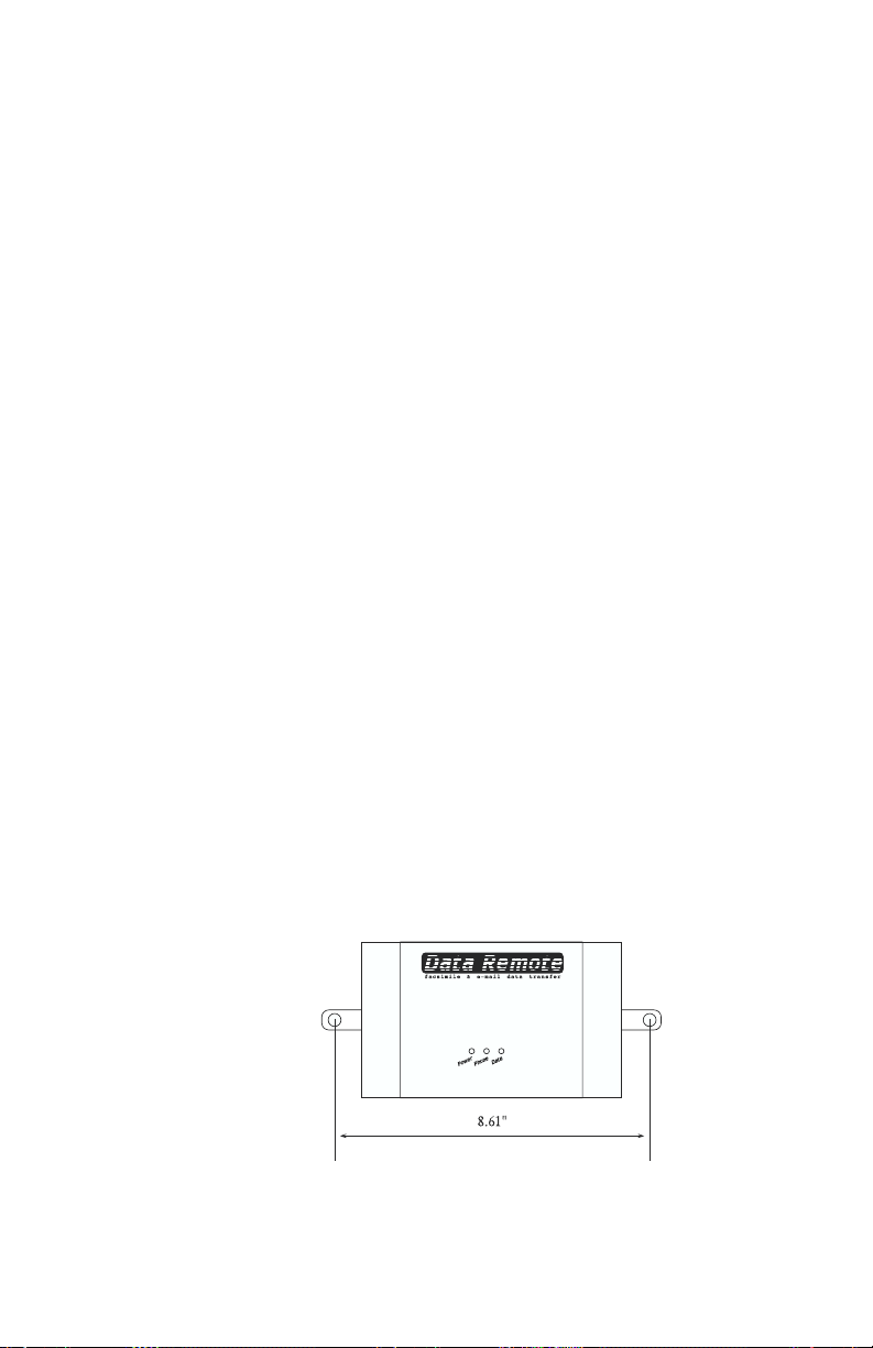
The Data Remote is designed to be wall mounted using two screws (up to .25"
diameter screws). Attach the screws to the wall 8.61" apart, through the holes
on either side of the unit, at the desired height from the floor. Tighten the
screws enough so the unit does not move. Refer to Fig. 2.1.
Fig. 2.1 Mounting Data Remote
13
Page 14

Data Remote User’s Manual
Power and Telephone Line
Data Remote is provided with an AC power transformer that must be plugged
into a standard 120VAC outlet. The phone jack on Data Remote must be
plugged into a standard telephone line. Data Remote will operate with all
standard telephone systems that accept pulse or tone dialing. It may not be
installed on a party line or pay telephone line.
Certain private telephone systems and public switching equipment may not
accept Data Remote’s dialing or may generate an unacceptable ring signal. In
those cases, a dedicated line may be required. Consult the supplier of your
telephone system if you encounter problems.
If you do not have a modular telephone extension at Data Remote’s location,
you must contact your local telephone company to have one installed (there is
a charge for this service). If you have four-pin jacks, adapters are available to
convert them to the modular plugs. Contact your local telephone company or
electronics parts store.
IMPORTANT - Never install telephone wiring during a lightning
storm. Never install telephone jacks in wet locations unless the
jack is specifically designed for wet locations. Never touch
uninsulated telephone wires or terminals unless the telephone line
has been disconnected at the network interface. Use caution when
installing or modifying telephone lines.
Power Surge Protection
Data Remote can be damaged by power surges and lightning through the
telephone line and the 120VAC power supply. Although Data Remote has
built-in surge protection, we recommend that additional protection be
obtained for the unit and for any electronic equipment that is attached to
your power supply and telephone lines. Power surge protection is especially
important if you live in a lightning prone area. The ISOTEL Surge Protector
Model IB-4 is available through Phonetics.
Connecting Data Remote to Your Device
Using a shielded serial cable, connect the RS232 port on your device to Data
Remote’s “Data In Port.”
A shielded cable is required to meet FCC regulations.
14
Page 15

Chapter 3: Communications Setup
Chapter 3: Communications Setup
nce you have installed your Data Remote unit, you must set up
O
communications before you can begin programming.
To communicate with DATA REMOTE you must have the following:
1. IBM PC/AT/XT or compatible with a RS232 serial port
2. Hayes compatible modem (only necessary for remote communications)
3. Terminal emulation software (i.e. MS Windows HyperTerminal,
Procomm, ...)
4. Serial port cable
You can communicate with DATA REMOTE in two ways:
1. Locally, through one of your PC’s RS232 COM ports linked to DATA
REMOTE’s Programming Port.
2. Remotely, through a modem connected to the PC and to DATA
REMOTE’s built-in modem.
Using HyperTerminal in Windows 95 to Communicate Locally
Communicating locally means that you are directly connecting your computer
to the Data Remote using one of your computer’s serial Com ports. Connect
a cable from one of your Com ports to the Data Remote “Programming Port.”
Windows 95 includes a communications program called HyperTerminal,
which you can use to communicate with Data Remote. To run
HyperTerminal, follow the steps below:
1. Click the “Start” button from Windows 95. Position the mouse
pointer over Programs, then Accessories, and then finally to
HyperTerminal. Click once on HyperTerminal.
2. Double-click Hypertrm.exe and HyperTerminal will start.
3. Type “Data Remote Local” in the Name: box, select an icon, and
click OK.
4. Next to Connect using, click the down arrow and select the Com
port number that corresponds to the one connected to Data
Remote’s Programming Port. Click OK.
5. On the Port Settings form, set Bits per second: 9600, Data bits: 8,
15
Page 16

Data Remote User’s Manual
Parity: none, Stop bits: 1, Flow control: none. Click OK.
6. Press <Enter> and you should get a PASSWORD: prompt. Enter
your password or press <Enter> if a password has not been
programmed. At the Data Remote> prompt you are on-line and
ready to program.
Once you have setup HyperTerminal the first time, you can communicate in
the future just by clicking the icon “Data Remote Local.ht” from the
HyperTerminal program group.
Using HyperTerminal in Windows 95 to Communicate Remotely via
Modem
Communicating remotely means that you are using your computer’s modem
and your telephone service to communicate with Data Remote. If you are
using an external modem, turn it on now. Windows 95 includes a communications program called HyperTerminal, which you can use to communicate
with Data Remote. To run HyperTerminal, follow the steps below:
1. Click the Start button from Windows 95. Position the mouse
pointer over Programs, then Accessories, and then finally to
Hyperterminal. Click once on HyperTerminal.
2. Double-click Hypertrm.exe and HyperTerminal will start.
3. Type “Data Remote Phone” in the Name: box, select an icon, and
click OK.
4. On the Phone Number form, enter the telephone number of your
Data Remote. Next to Connect using, click the down arrow and
select the name of your modem. Click OK.
5. On the Connect form, Click Dial and HyperTerminal will call the
Data Remote.
6. When your modem connects you will receive the message
CONNECT on your screen, followed by the PASSWORD: prompt.
Enter your password or press <Enter> if a password has not been
programmed. At the Data Remote> prompt you are on-line and
ready to program.
Once you have setup HyperTerminal the first time, you can communicate in
the future just by clicking the icon “Data Remote Phone.ht” from the
HyperTerminal program group, then click the call button.
Using Microsoft Windows 3.1 “Terminal”
“Terminal” Communications Setup - The “Terminal” communications
16
Page 17

Chapter 3: Communications Setup
settings may need to be changed in order for your PC to communicate with
Data Remote. To change these settings, follow the steps below.
A. Run Microsoft Windows 3.1.
B. Locate and double-click on the “Terminal” program icon, within the
ACCESSORIES program group.
C. Pull down the “Settings” menu and choose “Communications.”
D. In order for your PC to communicate with Data Remote the
Communications settings should be:
Connector: The COM port connected to Data Remote (if this is set at
“none,” the other settings will not be selectable)
Baud Rate: 9600
Data Bits: 8
Stop Bits: 1
Parity: None
Flow Control: None
Parity Check: No (empty box)
Carrier Detect: No (empty box)
• Change the Communications settings to the above and click OK.
E. Once you have changed the communications settings, you must save
the changes. This is done by pulling down the “File” menu and
selecting “Save As.” Save the terminal settings as a file called
dremote.trm.
F. To use these settings in the future, all that you need to do is open the
file dremote.trm while running Windows Terminal.
Local Communication through Programming Port
To communicate locally using your PC, you must first hook up Data Remote’s
Programming port to one of your PC’s RS232 COM ports. Data Remote’s
Programming port is located on the unit next to the phone jack and is labeled
“Programming Port.”
17
Page 18

Data Remote User’s Manual
To connect your PC to Data Remote’s Programming port, do the following:
1. Connect your PC’s com port to Data Remote’s Programming Port.
Make sure that you are connecting to one of your PC’s com ports and
not to a parallel port.
2. Run Windows Terminal and open the file dremote.trm. Press enter.
Enter your password at the password: prompt or press enter if a
password has not been programmed. At the
you are on-line and ready to program.
Remote Communication
You may communicate with Data Remote remotely (using phone lines) via a
modem. To do this, you must have a Hayes compatible modem connected to
your PC and modem communications software (Microsoft Windows
Terminal, Procomm, etc.). The following example shows how to set up
communications using Microsoft Windows “Terminal”.
A. Select the file dremote.trm created in the “Terminal” Communications
Setup section. This file contains all the settings necessary to communicate with Data Remote.
B. Change your Com port setting to the port that your modem is on.
C. Pull down the “Phone” menu and choose “Dial.” Enter the phone
number to dialed.
Your PC’s modem will call Data Remote. When it connects, you will receive
the message CONNECT on your screen, followed by the password: prompt.
You are now on-line and ready to begin programming.
D. Enter your password or press enter if a password has not been
programmed.
E. At the Data Remote> prompt, you are on-line and ready to program.
Data Remote> prompt,
RS232 Specifications
Programming Port
DB25 socket configuration: DCE female
Start/Stop protocol: None
9600 bps port speed
Communications protocol: 8 data bits, no parity, 1 stop bit
RS232 pin assignment (refer to diagram below):
18
Page 19

Pin Signal Symbol Direction
1 Frame Ground FG N/ A
2 Transmitted Data TD to Data Remote
3 Received Data RD from Data Remote
6 Data Set Ready DSR from Data Remote
7 Ground SG N/A
Data In Port
DB25 socket configuration: DCE female
Start/Stop protocol: user programmable (none, XON/XOFF, RTS/CTS)
User programmable port speed (default: 9600 bps)
Communications protocol: 8 data bits, no parity, 1 stop bit
RS232 pin assignment (refer to diagram below):
Pin Signal Symbol Direction
1 Frame Ground FG N/ A
2 Transmitted Data TD to Da ta Remote
3 Received Data RD f rom Data Remote
4 Request to Send RTS to Dat a Remote
5 Clear to Send CTS from Data Remote
6 Data Set Ready DSR from Data Remote
7 Ground SG N/A
20 Data Terminal Ready DT R to D ata Remote
Chapter 3: Communications Setup
Note -
If the direction of data flow between your device and Data
Remote conflict, you can use a null modem cable/adapter to
correct this problem. Contact your local computer supply store to
obtain this accessory.
19
Page 20

Data Remote User’s Manual
20
Page 21

Chapter 4: Programming
rogramming Data Remote is a simple procedure. The system setup
and standard functions are accomplished by using two types of short
P
commands, KEYWORD commands and STAND ALONE commands.
At a Data Remote> prompt you can always type “help” to get a listing of all
the commands.
Note - While on-line with Data Remote, transmissions will not occur.
Once you are off-line, Data Remote will begin transmissions again.
COMMAND KEYWORD
DIAGNOSTICS ALARM
EXIT AUTOREQUEST
HELP CLOCK
PATCH CONFIGURE
SET COVER
SHOW DESTINATION
For keyword commands: Shown in italics are the keyword command prefixes,
“set” and “show.” One of these prefixes must precede a keyword command.
“Set” allows you to change or program a parameter, “show” allows you to view
parameters.
At a Data Remote prompt (Data Remote>), type in a keyword after “set” or
“show.” Changes can only be made with the “set” command prefix.
For example, to set the time, type “set clock.” (“Clock” is the keyword):
Data Remote>set clock
Then pick from listed choices, or type new information, to change each
parameter. Type new information after the prompt (:), and then press enter.
The time is 11:18:37 PM Enter time:
The date is Tuesday 7/31/96 Enter date:
To leave the existing information as it appears, press enter.
For stand-alone commands: Use without “set” or “show.” Type a stand-alone
command at a Data Remote prompt.
For example, type “diagnostics” as the stand-alone command:
Data Remote>diagnostics
Chapter 4: Programming
REPORT
SYSTEM
21
Page 22

Data Remote User’s Manual
A list of function choices is then displayed. Enter the number for your listed
choice.
Data Remote Diagnostic Menu
<1> Clear data buffer
<2> View data buffer
<3> Data port monitor
<4> Test a destination
<5> View call failure log
<6> Reset all memory to factory default
<esc> Return to Data Remote> prompt
which?
To use either type of command, simply type the command word(s) after a
Data Remote prompt (Data Remote>) and then press the “Enter” key.
To get a Data Remote prompt at any time press the “Esc” key.
At any Data Remote prompt, you may type “help” to view the main menu of
keyword commands and stand alone commands.
NOTE
- You may abbreviate the prefix and the keyword by using
only the first few letters of each word. For example, the command
“show system” might also be typed as “sh sy.” The command “set
clock” may be typed as “se cl.” This applies for all of the commands. However, the abbreviation “co” will bring up the “cover”
keyword; to activate configuring, you must type at least the
letters“con.”
KEYWORD COMMANDS
There are two main components of all keyword commands: 1) the command
prefix word, “set” or “show;” 2) followed by one of the eight keywords.
“Show” lists the current values of a parameter. “Set” allows you to make a
change to that parameter.
The keywords represent all system and programming parameters. The format
for using a keyword command is:
Data Remote>set (keyword) or
Data Remote>show (keyword)
The keywords, in the order we’ll cover them, are:
SYSTEM
COVER
ALARM
CLOCK
CONFIG
AUTOREQUEST
22
Page 23

SYSTEM
Chapter 4: Programming
REPORT
DESTINATION
You may specify which item you want to program or query for certain alarm
or destination parameters. To do this, type “set” or “show” followed by the
keyword and the number of the alarm or destination.
For example, to show the programming for destination number 3 where you’ve
connected a fax modem, type:
Data Remote>show destination 3
The following will appear:
# NAME TYPE FUNCTION DESTINATION
03 Office Fax Machine FAX REPORT 5551234
This keyword allows you access to the following system parameters:
• Operating mode
• Handshaking
• Alphanumeric page speed
• Dial out prefix
• Rings to answer
• Wait time between calling rounds
• Attempts per destination
• DATA IN port baud rate
• Automatic daylight savings update
• Password
SHOW SYSTEM
To display the current system information and global parameter values, type
“show system” at a Data Remote prompt:
Data Remote>show system
Handshaking is off
Alphanumeric page speed is 1200
Dial out prefix:
Rings to answer: 3
Wait time between calling rounds (min.): 3
Attempts per destination: 3
Data In port baud rate: 9600
Automatic daylight savings update enabled
Operating mode is standard
23
Page 24

Data Remote User’s Manual
SET SYSTEM
To change the system parameters, type “set system” after any Data Remote
prompt. Data Remote will prompt you to type in your choice or “?” for a
description of the choices for each item. Enter new information after the
prompt(:). Press ENTER to go to the next parameter:
Data Remote>set system
Enable handshaking? (1,2,3,?) <1>:
Set alpha-page speed? (1,2,?) <1>:
Enter Dial out prefix: <>:
Enter number of rings to answer <1>:
Enter wait time between calling rounds (min.) <2>:
Enter number of attempts per destination <2>:
Enter Data In port baud rate (1200,2400,4800,9600,19200,38400)
<2400>:
Enable automatic daylight savings update? (y/n) <N>:
Enter new Password: XXXXXXXX
Operating mode (1, 2, ?) <1>:
SYSTEM PARAMETERS
Operating mode
Data Remote can operate in two different modes: (1) Standard and (2) AT
Command. The two modes determine how Data Remote will function and
respond to data entering the Data In port. The majority of users will operate
the unit in standard mode. AT Command mode will allow users with
intelligent equipment to control the messaging functions of Data Remote
from their equipment directly. The default operating mode is set to standard.
(1) Standard mode: Data Remote will collect data, send reports, detect alarm
keywords and send alarm messages automatically.
(2) AT Command mode: Data Remote will be controlled by the external
equipment connected to the Data In port. In this mode the equipment
determines when to send a report or alarm message by issuing specific AT
Commands. While in AT Command mode, messages may only be sent via
FAX or modem.
Once the operating mode is set to the AT Command mode and you are offline, Data Remote will accept AT commands at the Data In port. Any
standard AT command is accepted along with two special Data Remote
commands, AT~F and AT~D.
AT~F puts Data Remote into FAX dial-out mode. This will cause any dial out
attempt using ATDT to attempt a FAX transmission. Any text received
immediately after the ATDT command will be sent as a FAX. A two-second
period of nonactivity will end the report. AT~D puts Data Remote into
normal dial-out mode. This will make ATDT function normally.
24
Page 25

Chapter 4: Programming
Handshaking (Enable)
This is the handshaking protocol between Data Remote and the device
sending it ASCII data through the DATA IN port. Set this to match the
handshaking protocol of your device.
Programmable handshaking protocols: (1) None, (2) XON/XOFF, (3)
RTS/CTS
Default setting: None
Alphanumeric Page Speed (Set)
This is the baud rate of the data connection between Data Remote and your
alphanumeric pager service. Set this to the maximum rate your pager service
will accept.
Programmable settings: (1) 1200, (2) 300
Default setting: 1200
Dial out prefix
On some phone systems, Data Remote may need to dial initial digits to reach
an outside line before it can dial a telephone number.
Example: 9 P (P = 2 second pause)
(See special Dialing Codes later in this chapter)
Rings to answer (Enter number)
This is the number of times Data Remote will let the phone ring before it
answers an incoming call. When rings to answer is set to 0, Data Remote will
not answer incoming calls.
Programmable range 0 - 9 rings
Default setting 1 ring
Wait time between calling rounds (minutes)
This is the number of minutes Data Remote will wait before starting a new
round of calls.
Programmable range: 1 - 9 minutes
Default setting: 1 minute
Attempts per destination
This is the total number of times Data Remote will dial through a list of
destinations to attempt to deliver either an alarm or a report. If a transmission
to a destination was successful, that destination will not be contacted again.
Data Remote will only make additional attempts to contact a destination if
that destination hasn’t successfully received its transmission (due to a “no
25
Page 26

Data Remote User’s Manual
answer,” “busy signal,” “no carrier,” etc.). If a transmission fails to reach a
destination after the last attempt is completed, the failure is recorded in the
call failure log (see “Diagnostics” later in this chapter).
Programmable range: 1 - 5 attempts per destination
Default setting: 3 attempts per destination
Data In port baud rate
This is the speed of the RS-232 serial data connection between Data Remote
and the device sending it data.
Programmable settings: (1) 1200, (2) 2400, (3) 4800, (4) 9600, (5)
19200, (6) 38400
Default setting: 9600
Automatic daylight savings update
This parameter instructs Data Remote to automatically correct the time twice
a year for daylight savings.
Password (Enter New Password)
The password can be any combination of numbers or letters up to 32
characters long. The password is case sensitive. You must enter the password
exactly as it was originally programmed, with capitals, lowercase letters,
punctuation, etc. To clear the password, press the spacebar and enter. If the
password is forgotten, see the Troubleshooting section. Note: try not to lose
or forget your password, as resetting it (as outlined in “Troubleshooting”) will
reset all programming.
CLOCK
26
Data Remote has a battery-backed real-time clock that stores the time and
date. To display the current time and date, type “show clock” after a Data
Remote prompt:
Data Remote>show clock
The time is 8:47:27 AM
The date is Tuesday 3/26/96
To change the time and/or date, type “set clock” after a Data Remote prompt.
Enter the new time (hours, minutes, seconds) after the prompt (:). Time may
be entered in either 24 hour (0:00 = midnight) or 12 hour (enter AM or PM
after time) formats. Time will always appear in a 12 hour format.
Press “enter” to go to the date parameter after setting the clock.
Page 27

CONFIG
Chapter 4: Programming
Data Remote>set clock
The time is 11:18:37 PM Enter time: 8:37:00 AM
The date is Tuesday 7/31/96 Enter date: 8/2/96
CONFIG allows you to configure the PATCH -- the means of communicating directly with the device plugged into the Data Remote’s DATA IN Port. It
offers four PATCH-related options:
1) Include PATCH Data in data buffer?
The Data Remote will ask if you would like to include any data that results
from your communication session, to be saved in the data buffer of Data
Remote for later delivery. If you choose Yes, this data will be included in your
reports from Data Remote. If you choose No, Data Remote will simply ignore
any data entering the Data In Port until you exit from Patch mode.
2) Scan alarms while in PATCH mode?
The Data Remote will ask if you would like it to continue to scan for alarm
keywords during your Patch session. If you choose Yes, Data Remote will
continue to scan for alarm keywords and will respond to them as soon as the
on-line session with Data Remote is finished. If you choose No, Data Remote
will ignore any alarm keywords that may enter the Data In Port during your
patch mode session.
3) Enter logon mode?
The Data Remote will ask you to select a logon mode. The logon mode will
give you the option of going directly to patch mode when calling-in to Data
Remote. This can be done with or without password protection. There are
three modes to choose from:
(1) Normal - Normal logon means that when you call Data Remote you
will be asked to enter the password. If the password is entered correctly you
will go on-line with Data Remote.
(2) Protected - Protected logon means that when you call Data Remote
you will be asked to enter the password and then go directly to patch mode.
(3) Direct - Direct logon means that when you call Data Remote you will
go directly to Patch mode with no password prompt.
4) Enter PATCH exit character as ASCII number.
To exit PATCH mode and go on-line with Data Remote you must type the
Patch exit character. The Data Remote will ask you to enter a Patch exit
character. This is the ASCII character that exits patch mode (and Data Port
Monitor mode) and returns you to a Data Remote prompt. The default
character is ESC (which is ASCII 27). A table of ASCII characters and their
corresponding codes is included on a separate page in this addendum. This
27
Page 28

Data Remote User’s Manual
parameter is programmable just in case your equipment uses the ESC key for
performing other functions. Also, the patch exit character will only be
accepted if there is one second of silence following the transmission of the
character.
Sample of the CONFIG Command:
DATA REMOTE> set config
Include PATCH data in data buffer? (Y/N) <N>:
Scan alarms while in PATCH mode? (Y/N) <N>:
Enter logon mode (1,2,3,?) <1>:
Enter patch exit character as an ASCII number <27>:
DATA REMOTE> show config
Include PATCH data in data buffer: N
Scan alarms while in PATCH mode: N
Logon mode: Normal
Patch exit character: 27
COVER
28
Data Remote can send a cover page with a FAX, modem, or E-mail transmission. Sending a cover page with modem and E-mail transmissions is optional.
The cover page will include the date, time, the words “Data Remote Cover
Page,” and three user programmable lines of text. The three lines of text that
you can program are labeled as follows: “TO #1,” “FROM #1,” “FROM #2.”
Each line can contain up to 32 characters of text, including spaces. For fax
transmissions FCC regulations require that the phone number of your Data
Remote unit be included in at least one of the “FROM” lines. These lines
create the standard cover page for your Data Remote unit and will be sent with
all fax, modem, and e-mail transmissions that include a cover page.
Note - The “FROM #1” line will be sent as part of all alphanumeric
alarm messages.
To further personalize each transmission, the cover page will automatically
include the Destination name and number for each transmission, as programmed in the Destination field. See the Destination section later in this
chapter for detailed information.
To display the current cover page information, type “show cover” after a Data
Page 29

ALARM
Chapter 4: Programming
Remote prompt.
Data Remote>show cover
Cover page will be sent with modem and email transfers
TO #1: Engineering
FROM #1: Data Remote #3 @ 610-555-1234
FROM #2: McHenry Processing Plant
To change cover page information, type “set cover” after a Data Remote
prompt. Each information field holds up to 32 characters. Enter the new
information after the prompt (:). Press ENTER to go to the next parameter.
Data Remote>set cover
Send cover page with modem and Email transfers? (y/n) <Y>:
Enter TO #1 <Engineering>:
Enter FROM #1 <Data Remote #3>:
Enter FROM #2 <McHenry Processing Plant>:
Data Remote can send alarm messages if it detects a period of inactivity on the
Data In port, or if it encounters any of 20 user-programmable alarm keywords. To stop an alarm message transmission that is in progress, press
control+C while connected locally to the unit via the Programming port.
The Data In Port Inactivity Alarm is useful to make sure equipment is
functioning. The inactivity alarm has a programmable range of 0 hours, 1
minute to 255 hours, 0 minutes. The default setting is 1 hour, 0 minutes.
An alarm keyword can be up to 16 characters. Data collected before and after
the keyword will be included in the alarm message. You can control the
number of characters included in an alphanumeric pager alarm by setting the
“Characters before keyword to alphanumeric pager” field. Data Remote can
send a maximum of 80 characters to an alphanumeric pager. The total of 80
characters is equated as shown below:
– the cover page “FROM #1” field (up to 32 characters)
– the alarm keyword (up to 16 characters)
– the number of characters before the keyword (up to 29 characters)
– the number of characters after the keyword, which will be derived from
the remaining number of characters, totalling 80.
If you use all the possible characters in the “FROM #1” field, the alarm
keyword, and those preceding the keyword, you will only be able to have 3
characters after it. Thus, you must decide if the data before or after the
keyword is the most important to you, and use your total 80 possible
characters accordingly.
The command “show alarm” will display the present setting of the inactivity
alarm and list all of the alarm keywords.
29
Page 30

Data Remote User’s Manual
To display the current alarm programming, type “show alarm” at a Data
Remote prompt:
Data Remote>show alarm
Characters before keyword to alphanumeric pager <16>:
Inactivity alarm is enabled at interval 1 hours 0 minutes
Alarm keyword 01: failure
Alarm keyword 02: emergency
Alarm keyword 03:
Alarm keyword 04:
Alarm keyword 05:
Alarm keyword 06:
Alarm keyword 07:
Alarm keyword 08:
Alarm keyword 09:
Alarm keyword 10:
Alarm keyword 11:
Alarm keyword 12:
Alarm keyword 13:
Alarm keyword 14:
Alarm keyword 15:
Alarm keyword 16:
Alarm keyword 17:
Alarm keyword 18:
Alarm keyword 19:
Alarm keyword 20:
Alarm keywords can be any combination of continuous numbers or letters up
to 16 characters long. Spaces are not permitted within alarm keywords and the
keyword, as sent from your device, must have a space before and after it. The
keywords are case sensitive. You must enter the keyword exactly as it will be
sent from the external device being monitored by Data Remote with capitals,
small letters, punctuation, etc.
To change the alarm parameters, type “set alarm” after a Data Remote prompt.
You may also change a specific alarm keyword by typing “set alarm” followed
by the entry number (1-20). Enter new information after the prompt (:). Press
enter to go to the next parameter.
Data Remote>set alarm
Enable inactivity alarm? (y/n) <Y>:
Enter inactivity alarm interval <1:00> hours: minutes:
Characters before keyword to alphanumeric pager <20>:
Enter alarm keyword #01 <failure>:
Enter alarm keyword #02 <emergency>:
Enter alarm keyword #03 <>:
Enter alarm keyword #04 <>:
Enter alarm keyword #05 <>:
Enter alarm keyword #06 <>:
Enter alarm keyword #07 <>:
Enter alarm keyword #08 <>:
Enter alarm keyword #09 <>:
Enter alarm keyword #10 <>:
Enter alarm keyword #11 <>:
Enter alarm keyword #12 <>:
Enter alarm keyword #13 <>:
Enter alarm keyword #14 <>:
Enter alarm keyword #15 <>:
Enter alarm keyword #16 <>:
Enter alarm keyword #17 <>:
Enter alarm keyword #18 <>:
Enter alarm keyword #19 <>:
Enter alarm keyword #20 <>:
30
Page 31

Chapter 4: Programming
Alarm messages
The following are sample alarm messages for three types of transmissions that
can be sent by Data Remote: Alphanumeric Pager, FAX, and E-mail.
Alphanumeric Pager
01:Data Remote #3 @
610-555-1234 boiler
<failure> at main p
lant Broad St.
Fax
DATA REMOTE COVER PAGE
TIME: 03:26:38 PM
DATE: 05/30/96
TO: J. McShane
FROM: Data Remote #3 @ 610-555-1234
Alarm keyword encountered: failure
8:11:05>current pressure reading 200 psi
8:11:05>high temperature limit exceeded
8:11:05>alarm situation: boiler failure at main plant Broad st.
8:11:05>**attention**
8:11:05>alarm situation: boiler failure at main plant Broad st.
8:11:05>auxiliary processes shutdown
8:11:05>current pressure reading 215 psi
E-mail
FROM: [email protected]
Subject: Email report from remote unit.
DATA REMOTE COVER PAGE
TIME: 03:26:38 PM
DATE: 05/30/96
TO: J. McShane
FROM: Data Remote #3 @ 610-555-1234
Alarm keyword encountered: failure
8:11:05>current pressure reading 200 psi
8:11:05>high temperature limit exceeded
8:11:05>alarm situation: boiler failure at main plant Broad st.
8:11:05>**attention**
8:11:05>alarm situation: boiler failure at main plant Broad st.
8:11:05>auxiliary processes shutdown
8:11:05>current pressure reading 215 psi
558-0222
Engineering
McHenry Processing Plant
PAGE 1 OF 2
558-0222
Engineering
McHenry Processing Plant
PAGE 1 OF 2
AUTOREQUEST
This command allows the Data Remote to send a text string of up to 64
characters periodically to the device connected to the Data In Port. The
31
Page 32

Data Remote User’s Manual
string may contain letters and numbers as well as ASCII characters. All ASCII
characters must be preceded by a backslash followed by 3 digits. For example,
a carriage return would be \013 and a line feed would be \010. (See ASCII
Table later in this manual)
Sample of an AUTOREQUEST command:
DATA REMOTE> set auto
Send periodic text string? (Y/N) <Y>:
Enter time interval to transmit string <1:00>: hours: 24 minutes: 00
Enter start time <—:—>: 8:00
Enter transmit string <>: download pump#10 rundata\013
DATA REMOTE> show auto
Periodic text string will be sent
Transmit at interval 24 hours 0 minutes
Start time: 8:00 AM
String: download pump#10 rundata\013
REPORT
32
Data Remote can send ASCII text reports via Fax, Modem, or E-mail to up to
32 destinations. A report consists of all data that has been collected at the
“Data In” port. Reports may be sent at a regular time interval or after Data
Remote receives a programmable amount of data (by volume). While the
current report is being sent, data is being collected for the next round of
reports. To stop a report transmission that is in progress, press control+C
while connected locally to the unit via the Programming port.
To display the current report programming, type “show report” at a Data
Remote prompt:
Data Remote>show report
Reporting by volume at 45 lines
Reporting by time interval at 1 hour 0 minutes
Report start time: 5:30 PM
The report start time and the time interval settings are used to control time
interval reporting. Report start time is the time of day Data Remote will begin
its time interval reporting. Once the report start time has passed, it will be
displayed as “_ _:_ _” when “show report” or “set report” is typed. Time may
be entered in either 24 hour (0:00 = midnight) or 12 hour (enter AM or PM
after time) formats. There is not a default start time.
Page 33

“Time interval” is the amount of time between reports. The “time interval”
will remain constant and has a programmable range of 0 hours, 1 minutes to
255 hours, 0 minutes. The default setting is 1 hour, 0 minutes.
To send reports by volume, set the number of lines to initiate report to the
desired number of lines. The programmable range is 1 to 750. The default
setting is 45.
To change the report parameters, type “set report” after a Data Remote
prompt. Enter new information after the prompt (:). Press ENTER to go to
the next parameter.
DESTINATION
Data Remote is capable of sending a report, an alarm message, or both to up
to 32 destinations. Destinations can be FAX machines, modems, E-mail
addresses, numeric pagers, or alphanumeric pagers.
Note - Data Remote uses the TAP protocol for alphanumeric
paging.
Chapter 4: Programming
Data Remote>set report
Report by volume? (y/n) <Y>:
Enter number of lines to initiate report <45>:
Report by time interval? (y/n) <Y>:
Enter time interval to initiate report <1:00> hours: minutes:
Enter report start time <_ _:_ _>:
Type “show destination” at a Data Remote prompt to display the name,
destination, dial out type, and function for each destination. You may also
display information for a specific destination by typing “show destination”
followed by the entry number: (1-32).
Data Remote>show destination
# NAME TYPE FUNCTION DESTINATION
01 Office Manager FAX REPORT 555-9876
02 J. McShane ALPHA ALARM 8675309a0504746
03 K. Davis PAGER ALARM 5552123PP5554498
04 K. Davis EMAIL BOTH [email protected]
05 Home PC MODEM BOTH 555-9101
06 FAX REPORT
07 FAX REPORT
08 FAX REPORT
09 FAX REPORT
10 FAX REPORT
11 FAX REPORT
12 FAX REPORT
13 FAX REPORT
14 FAX REPORT
15 FAX REPORT
16 FAX REPORT
17 FAX REPORT
18 FAX REPORT
19 FAX REPORT
20 FAX REPORT
21 FAX REPORT
22 FAX REPORT
23 FAX REPORT
33
Page 34

Data Remote User’s Manual
24 FAX REPORT
25 FAX REPORT
26 FAX REPORT
27 FAX REPORT
28 FAX REPORT
29 FAX REPORT
30 FAX REPORT
31 FAX REPORT
32 FAX REPORT
To change the name, destination, dial out type, and function for each
destination, type “set destination.” You may program information for a
specific destination by typing “set destination” followed by the entry number,
(1-32).
Data Remote>set destination
Type in new information after the prompt (:). Stop editing destinations by
pressing the “Esc” key at any time.
enter name 1 < >:
enter destination for number 1 < >:
enter dial-out type 1 <1,2,3,4,5,?> <1>:
enter function for number 1 <1,2,3,4,?> <1>:
Name
A field of up to 16 characters for a description of the destination which will
appear on the cover page. Enter the description at the prompt, then press
“Enter.”
34
Destination
The actual telephone number or E-mail address Data Remote contacts to
deliver its report or alarm message. The destination will appear on the cover
page and can be up to 36 characters long, up to 64 digits long for E-mail
addresses only. It may consist of numbers, letters, and special dialing codes.
See the Dialing Codes section for details. Enter the destination at the prompt,
then press enter.
Dial Out Type
This is used to specify the type of call Data Remote will make to a particular
destination. Data Remote will prompt you to type in your choice (1-5) or “?”
for a list of your choices: (1) Fax, (2) Modem, (3) E-mail, (4) Pager, (5)
Alphanumeric Pager.
Fax
This instructs Data Remote to send a fax transmission to either a fax machine
or a PC with the ability to receive a fax directly.
Page 35

Chapter 4: Programming
Modem
This instructs Data Remote to send a message to a modem. This would
typically be a modem connected to a computer. Communication software
capable of automatically receiving the message must be running on the
computer.
This instructs Data Remote to deliver a message to the E-mail address
programmed in the destination field. E-mail registration through Phonetics is
required. See the E-mail Registration Form, enclosed with your Data Remote.
Pager
This instructs Data Remote to dial a numeric pager and leave a number on the
display.
Alphanumeric Pager
This instructs Data Remote to send a text message to an alphanumeric pager.
Function
Data Remote can send two types of transmissions, reports and alarms. Data
Remote will prompt you to type in your choice (1-4) or “?” for a list of your
choices. The available dial-out functions are: (1) report, (2) alarm, (3) none,
or (4) both. Alarm dial outs may be sent to any destination, but Report dial
outs are only valid for Fax, Modem, and E-mail destinations.
Dialing Codes
Sometimes Data Remote may need special instructions when dialing out on
certain phone systems, to access an outside phone line, to contact numeric
pagers, or to use alphanumeric pager services. The following dialing codes
give Data Remote instructions on how to set the phone digits when dialing
the phone number. Each code is counted as one digit toward the total of 64
digits. The dial out codes are:
P = a two-second pause. A two-second pause can be placed anywhere within
the phone number by typing the letter P (upper or lower case). The pause
takes up one digit and may be used more than once.
POUND (#) or ASTERISK (*): When dialing to a numeric pager, a pound
sign (#) or an asterisk (*) may be used within the phone number.
Example: 1 6105554591 PP 986033 #
When dialing to a numeric pager it is sometimes necessary to combine codes.
35
Page 36

Data Remote User’s Manual
Certain pager systems vary and you must adjust accordingly. To test your
pager system, use an extension telephone on the same line as the Data Remote
unit and listen in during Data Remote’s dial out to confirm that your pager
service is reached without a problem. If you must add a pause, use the letter P
to insert a two second pause wherever necessary.
Special Alphanumeric Pager Dialing Codes
A = alphanumeric pager ID (required)
W = alphanumeric character password (optional)
A = alphanumeric pager ID: The ‘A’ dialing code is used ONLY for alphanumeric pager destinations. It is placed between the pager company’s telephone
number and a particular pager’s ID number by typing the letter A (upper or
lower case). It instructs Data Remote to wait until a connection is made to the
alphanumeric pager service’s computer system before transmitting the ID
number for a particular pager.
Example: 1-610-555-4593 A 0504099
W = alphanumeric character password: The ‘W’ dialing code is used ONLY
for alphanumeric pager destinations and only if your particular pager system
requires a character password. This password may be required for Data
Remote to access the pager service’s computer system. If required, it is placed
between the pager company’s telephone number and the required character
password in the dial out sequence by typing the letter W (upper or lower case).
The character password must precede the pager ID number.
Example if character password required:
(pager company phone #)W(character password)A(pager ID #)
1-610-555-4593-W-000000-A-0504099
The alphanumeric character password is optional and, in general, is reserved
for future services. Length of the password, when used, may be different in
some systems. Consult your pager service for more information.
Stand Alone Commands
The STAND ALONE commands are used without the command prefix “set”
or “show” to execute an action. The STAND ALONE commands are:
PATCH
HELP
DIAGNOSTICS
EXIT
36
Page 37

PATCH
HELP
Chapter 4: Programming
This command enables you to communicate directly with the external device
connected to Data Remote’s DATA IN port. You can use this command while
on-line locally or remotely. Remember, transmissions will not occur while you
are on-line with Data Remote. (See also CONFIG section earlier in this
chapter.)
To communicate with an external device connected to the DATA IN port,
type “patch” after a Data Remote prompt:
Data Remote>patch
Press “Esc” to exit patch mode and return to a Data Remote prompt.
The HELP command provides a list of all valid KEYWORDS and STAND
ALONE commands.
To display the command list, type “help” after a Data Remote prompt:
Data Remote>help
Command Keyword
_______ _______
DIAGNOSTICS ALARM
EXIT AUTOREQUEST
HELP CLOCK
PATCH CONFIG
SET COVER
SHOW DESTINATION
REPORT
SYSTEM
DIAGNOSTICS
The Diagnostics command provides the ability to perform communication
diagnostic functions. To display the list of diagnostic functions, type
“diagnostics” after a Data Remote prompt:
Choose a function. After “which?” type the number that appears in brackets
<>, corresponding to your selection.
Data Remote>diagnostics
Data Remote Diagnostic Menu
<1> Clear data
<2> View data
<3> Data port monitor
<4> Test a destination
<5> View call failure log
<6> Reset all memory to factory default
<esc> Return to Data Remote> prompt
which?
37
Page 38

Data Remote User’s Manual
Clear Data
This will delete any accumulated data.
View Data
This displays any accumulated data.
Data Port Monitor
This displays data coming into the DATA IN port on the screen in real time.
Press “Esc” to exit mode and return to a Data Remote prompt.
Test a Destination
This is used to send a test transmission to one of Data Remote’s 32 destinations. For Fax, E-mail, Data, and Alphanumeric Pager destinations, Data
Remote will send the message “Test transmission from Data Remote” to the
specified destination number. For numeric pager destinations, Data Remote
will call and deliver the programmed digits to the pager.
View Call Failure Log
The call failure log keeps track of the 10 most recent transmissions that failed
to reach their destinations after completing all of the programmed number of
calling rounds. This function will display the destination number, the date
and time of the call, and the reason for the failure.
Reset All Memory to Factory Default
This function will erase all user programmed information, clear any accumulated data, and reset Data Remote’s programming back to factory defaults.
EXIT
This command “logs” you off from an on-line programming session with Data
Remote. If you do not log off, Data Remote will automatically log off after 5
minutes of idle time.
Note - alarm and report dial outs cannot occur while you are online.
To log off Data Remote, type “exit” after a Data Remote prompt.
Custom Codes
There are also three commands that can be programmed into the ASCII text
string sent from the device connected to the Data In Port. These commands,
when encountered, will execute specific automatic functions in Data Remote.
Each begins with a backslash and ends with a backslash. The two characters in
38
Data Remote>exit
Page 39

Chapter 4: Programming
between define the function to be carried out. These functions include
clearing the Data Remote data buffer, sending reports on-demand, or sending
an alarm message on-demand. The commands are described below:
\CB\ - This command will clear the data buffer when received at the
Data In Port.
\GS\ - This command will instruct Data Remote to immediately send
the contents of the data buffer to the destinations selected to receive
reports. Reporting must be turned on for this command to function.
The contents of the data buffer will be cleared when report delivery is
completed.
\GA\ - This command will instruct Data Remote to immediately send
an alarm message to those destinations selected to receive alarms. The
alarm message will include the previous 512 characters received at the
Data In Port prior to receiving the \GA\ command.
39
Page 40

Data Remote User’s Manual
40
Page 41

Chapter 5: Troubleshooting
Check to see which port you’re currently
plugged into. The Programming Port is
located to the right of the Data In Port,
next to the Phone jack.
Check to be sure that you have plugged
into the serial port on your PC. If you’re
not sure, check the manual for your
specific computer.
Chapter 5: Troubleshooting
Set your communications software for
9600 baud, (8) data bits, no parity and (1)
stop bit.
Check the connection at the Data Remote.
The Data In Port is the lefthand port, the
‘Programming Port’ is in the middle.
Problem Cause Solution
Your computer is connected to the ‘Data
In Port’ instead of the ‘Programming
Port’.
1. The Data Remote
cannot be programmed
from a local computer.
The data remote is connected to your
computer’s parallel port instead of the
serial port.
Your communication software isn’t
configured properly.
Your equipment is connected to the
‘Programming Port’ instead of the ‘Data
In Port.’
2. Data Remote is not
responding to the
connected equipment.
41
Page 42

Data Remote User’s Manual
You will need to insert a null modem cable/adaptor
between your equipment and Data Remote.
Check the system menu in data remote and make
sure the DATA IN PORT Baud rate matches your
equipment. Data Remote can receive information at
many baud rates but it must be in the format (8)
data bits, no parity, and (1) stop bit.
To check this problem further: Connect your
computer to the programming port and your
equipment to the Data In port. Go on-line with Data
Remote and type “Diagnostics.” Select item (3)
Data Port Monitor. You can now view, in real
time, the data sent from your equipment to Data
Remote. Scrambled data indicates a baud rate or
data format problem.
Problem Cause Solution
42
The serial port on your equipment is
wired as a DCE device causing a
conflict with Data Remote.
The communication parameters for your
equipment do not match the parameters
in data remote.
Page 43

Chapter 5: Troubleshooting
In order for e-mail to be transmitted you must
register the phone number that Data Remote will be
calling from and pay a monthly fee for e-mail service
through Phonetics.
Check the email address as programmed.
Check, and possibly re-enter, the alarm keyword. At
the Data Remote prompt, type “sh al” to see the
one continuous word
Alarm settings and keywords list. Make sure the
or set of numbers (up to 16 characters long).
words are entered correctly. Keywords are case
sensitive and must be typed as
Check the alarm keywords list and make sure
incoming data has a space or carriage return before
and after the keyword.
The phone number that Data Remote is
Problem Cause Solution
3. Data Remote is
calling from is not registered at Phonetics.
programmed to send
reports via e-mail, but
The e-mail address is entered incorrectly.
The e-mail address is not accessible via the
the reports are never
received.
internet.
Phone number is incorrect — either calling
from Canada or a prefix is required.
The keyword is not spelled correctly or
has mismatched small-case and capital
letters.
4. Data Remote is
programmed to send an
alarm message when a
keyword is detected, but
an alarm message is
never received.
The keyword does not have a blank space
before and after it.
43
Page 44

Data Remote User’s Manual
Unplug the power supply. Remove the four screws
on the sides of the enclosure and lift the cover off.
Locate the lithium battery (about the size of a
dime). Next to the battery is a four pin header with a
black jumper. Remove the jumper for 10 seconds
and then put it back. Replace the cover and plug in
all programming back to the default
the power supply. This will clear the password and
parameters.
reset
Problem Cause Solution
44
5. Data Remote will
not accept your
password or you have
forgotten your
password.
Page 45

Appendix A: ASCII TABLE
Appendix A: ASCII Character TABLE
Number Key
0 CTRL/1
1 CTRL/A
2 CTRL/B
3 CTRL/C
4 CTRL/D
5 CTRL/E
6 CTRL/F
7 CTRL/G
8 CTRL/H, BACKSPACE
9 CTRL/I, TAB
10 CTRL/J, LINE FEED
11 CTRL/K
12 CTRL/L
13 CTRL/M, RETURN
14 CTRL/N
15 CTRL/O
16 CTRL/P
17 CTRL/Q
18 CTRL/R
19 CTRL/S
20 CTRL/T
21 CTRL/U
22 CTRL/V
23 CTRL/W
24 CTRL/X
25 CTRL/Y
26 CTRL/Z
27 ESC, ESCAPE
28 CTRL<
29 CTRL/
30 CTRL/=
31 CRTL/32 SPACEBAR
33 !
34 “
35 #
36 $
37 _
38 &
39 ‘
40 (
Number Key
41 )
42 *
43 +
44 ,
45 46 .
47 /
48 0
49 1
50 2
51 3
52 4
53 5
54 6
55 7
56 8
57 9
58 :
59 ;
60 <
61 =
62 >
63 ?
64 @
65 A
66 B
67 C
68 D
69 E
70 F
71 G
72 H
73 I
74 J
75 K
76 L
77 M
78 N
79 O
80 P
81 Q
45
Page 46

Data Remote User’s Manual
Number Key
82 R
83 S
84 T
85 U
86 V
87 W
88 X
89 Y
90 Z
91 [
92 \
93 ]
94 ^
95 _
96 ‘
97 a
98 b
99 c
100 d
101 e
102 f
103 g
104 h
105 i
106 j
107 k
108 l
109 m
110 n
111 o
112 p
113 q
114 r
115 s
116 t
117 u
118 v
119 w
120 x
121 y
122 z
Number Key
123 {
124 |
125 }
126 ~
127 DEL
46
Page 47

Appendix B: Checking Your Data Remote for
Proper Operation
We recommend that you test your Data Remote weekly to be sure it is
functioning properly. This will ensure that when the need arises the Data
Remote will be ready to send a message to the appropriate personnel.
There are two tests that can be performed:
1) Call the unit with your modem and go online. This will test the unit’s
ability to answer the phone and make a modem connection. It will also
verify that the unit is receiving power and is functioning.
2) Make the unit send a report or message using the “Test a Destination” function located within the Diagnostics menu or force an alarm
keyword into the Data Port and allow the unit to contact all programmed telephone numbers. This will make sure that the Data Remote
is programmed properly. It will also prepare personnel to respond
appropriately when they receive a call from the Data Remote.
47
Page 48

Data Remote User’s Manual
48
Page 49

Appendix C: Technical Specifications
Communication Ports
RS232 Data In Port
Type: DB25 Female
Speed: 300 - 38,400 bps
Protocol: CTS/RTS, XON/XOFF, None
RS232 Programming Port
Type: DB25 Female
Speed: 9600 bps
Protocol: None
RJ11C Telephone Network Connection
Internal Modem
Data Modem Modes
• CCITT: V.32bis, V.32, V.23, V.22bis, V.22, and V.21
• Bell: 212A and 103
• Speeds: 14400, 12000, 9600, 7200, 4800, 2400, 1200, and 300 bps
• Industry standard ‘AT’ command set
Fax Modem Send and Receive Modes
• CCITT: V.17, V.29, V.27ter, and V.21 ch2
• Speeds: 14400, 12000, 9600, 7200, 4800, 2400, and 300 bps
• Supports Group 3 Fax
• EIA/TIA-578 Class 1 Fax ‘AT’ command set
• EIA/TIA-592 Class 2 Fax ‘AT’ command set
49
Page 50

Data Remote User’s Manual
V.42/MNP Protocols
• Error correction: V.42 and MNP 2 - 4
• Data Compression: V.42bis and MNP 5
Indicators
Power LED
Off-Hook LED
Data In LED
Power Requirements
External transformer 120VAC 4W/7.5VAC 500mA
Operating Temperature Range
0°C - 50°C (32° - 122° F)
Dimensions
Weight
50
9.5" x 6.0" x 1.5"
4 lbs.
Page 51

Appendix D: Returning the Unit for Repair
In the event that Data Remote does not function properly, we suggest that you
do the following:
1) Record your observations regarding Data Remote's malfunction.
2) We recommend that you call the Technical Service Department at
(610)558-2700 prior to sending the unit to Phonetics for repair.
If the unit must be sent to Phonetics for servicing, please do the following:
1) Unplug the AC power supply from the wall outlet, remove the
batteries, and disconnect all sensors from the alert inputs.
2) Carefully pack the unit to avoid damage in transit. Use the
original container (if available) or a sturdy shipping box.
3) You must include the following information to avoid processing
delays:
a) Your name, address, and telephone number.
b) A note explaining the problem.
4) Ship your package to the address below:
Service Department
Phonetics, Inc.
901 Tryens Road
Aston, PA 19014
5) Ship prepaid and insured via UPS or US Mail to ensure a
traceable shipment with recourse for damage or replacement.
51
Page 52

Data Remote User’s Manual
52
Page 53

in materials and craftsmanship with only the limitations and exclusions set out
below.
3. WARRANTY AND REMEDY: One-Year Warranty — In the event that the
Product does not conform to this warranty at any time during the time of one year
from original purchase, warrantor will repair the defect and return it to you at no
charge.
This warranty shall terminate and be of no further effect at the time the Product is
(1) damaged by extraneous cause such as fire, water, lightning, etc. or not
maintained as reasonable and necessary; (2) modified; (3) improperly installed; (4)
repaired by someone other than warrantor; (5) used in a manner or purpose for
which the Product was not intended; or (6) sold by original purchaser.
WARRANTORS’ OBLIGATION UNDER THIS WARRANTY IS LIMITED TO
REPAIR OR REPLACEMENT OF THE PRODUCT. THIS WARRANTY DOES NOT
COVER PAYMENT OR PROVIDE FOR THE REIMBURSEMENT OF PAYMENT OF
INCIDENTAL OR CONSEQUENTIAL DAMAGES.
It must be clear that the warrantors are not insuring your premises or guaranteeing
that there will not be damage to your person or property if you use this Product.
The warrantors shall not be liable under any circumstances for damage to your
person or property or some other person or that person’s property by reason of the
sale of this product or its failure to operate in the manner in which it is designed.
The warrantors’ liability, if any, shall be limited to the original cost of the Product.
The warrantors assume no liability for installation of the Product and/or interruptions of the service due to strikes, riots, floods, fire, and/or any cause beyond
Seller’s control.
4. PROCEDURE FOR OBTAINING PERFORMANCE OF WARRANTY: In the
event that the Product does not conform to this warranty, the Product should be
shipped or delivered freight prepaid to a warrantor with evidence of original
purchase.
5. LEGAL REMEDIES: This warranty gives you specific legal rights, and you may
also have other rights which vary from state to state to the extent allowed by law
expressly in lieu of any other express or implied warranty, condition, or guarantee.
Effective date 1/19/96
© 1996 Phonetics, Inc.
 Loading...