

Page 1

CPP Monitor 2000
User’s Manual
○○○○○○○○○○○○○○○○○
Version 3.0
. .
Crucial Power Products
9
Page 2

Contents
Important Safety Instructions..........................11
CAUTION...........................................................................12
FCC Requirements..............................................................12
Telephone Consumer Protection Act...................................14
Canadian Department of Communications Statement.........14
Chapter 1: Introduction...................................17
Programming Interface........................................................18
Technical Support...............................................................18
About This Manual..............................................................18
Chapter 2: Installation.....................................21
OPERATING ENVIRONMENT.............................................21
MOUNTING THE UNIT......................................................21
POWER SURGE PROTECTION...........................................22
BATTERY BACKUP..............................................................22
Turning the CPP Monitor 2000 on...............................................22
TELEPHONE LINE...............................................................23
Line Seizure.................................................................................24
INPUT CONFIGURATION..................................................24
WIRING SENSORS AND TRANSDUCERS...........................25
LED INDICATORS...............................................................26
Inputs 1-8 and Power:..................................................................26
Battery:........................................................................................26
System-On:..................................................................................26
Phone:.........................................................................................26
Chapter 3: Communications............................27
Installing and Starting the Software......................................27
Minimum requirements...............................................................27
Installation..........................................................................27
WINDOWS ‘95 INSTALLATION..................................................27
i
Page 3

CPP Monitor 2000 User’s Manual
WINDOWS 3.1 INSTALLATION..................................................28
Running the Software..........................................................28
CPP Monitor 2000 Menu Bar......................................................29
Communications Setup.......................................................30
Local Port Configuration..............................................................30
Modem Setup......................................................................30
Communication Status.................................................................31
Advanced Comm Setup...............................................................32
Options........................................................................................33
Options screen............................................................................34
Chapter 4: Programming..................................35
SETTING UP NEW UNITS...................................................35
Procedure....................................................................................36
COMMUNICATING WITH CPP MONITOR 2000................37
Local Communication..................................................................37
Modem Communication..............................................................37
Off-line Communication..............................................................38
MANAGING UNIT PROGRAMMING FILES........................38
To create a Data File:...................................................................38
To view a Data File Off-line:........................................................39
To delete a Data File:...................................................................39
To load an existing Data File into a CPP Monitor 2000 Unit:......39
SYSTEM PROGRAMMING..................................................39
System Identification...................................................................40
Unit Phone Number:...................................................................40
Unit Description:.........................................................................40
Clock:..........................................................................................41
Unit Date & Time.........................................................................41
Auto Daylight Savings..................................................................41
Dialout Settings:..........................................................................41
Dialing Method............................................................................41
Dialing Prefix...............................................................................41
Alpha Pager Speed.......................................................................42
Maximum Calling Rounds............................................................42
Voice Repetitions.........................................................................42
ACCESS:..............................................................................42
Acknowledgment Code................................................................42
Voice Password............................................................................42
ii
Page 4

Slave ID ....................................................................................... 43
Passwords .................................................................................... 43
Incoming Calls:............................................................................ 43
Rings Until Answer ...................................................................... 43
Carrier Wait T ime......................................................................... 43
INPUTS............................................................................... 43
ST A TUS T AB:....................................................................... 44
Input Name: ................................................................................ 44
Value (with units): ....................................................................... 44
Status:.......................................................................................... 45
State: ........................................................................................... 45
Min & Max:.................................................................................. 45
Clear Alarms: ............................................................................... 46
CONFIGURA TION TAB: ..................................................... 46
Input T ype:................................................................................... 46
Table Low & Table High: .............................................................. 46
Calibration:.................................................................................. 47
Label/Units: ................................................................................. 47
ALARM PROGRAMMING TAB:........................................... 48
Inputs Name: ............................................................................... 48
Alarm Low Limit: ......................................................................... 48
Alarm High Limit: ........................................................................ 49
Recognition Time: ........................................................................ 49
Call List:....................................................................................... 49
Alarm Enable/Disable: ................................................................. 50
Alarm Reset Time: ........................................................................ 50
MONITORS ........................................................................ 50
Displaying Input Monitors ........................................................... 50
Delete Input Monitors ................................................................. 51
Bar Reading: ................................................................................ 51
Low Limit:.................................................................................... 51
High Limit:................................................................................... 51
Low Alarm Limit: ......................................................................... 51
High Alarm Limit: ........................................................................ 52
Minimum Input Reading: ............................................................. 52
Maximum Input Reading: ............................................................ 52
Gauge Reading: ........................................................................... 52
Low Limit:.................................................................................... 52
High Limit:................................................................................... 53
Low Alarm Limit: ......................................................................... 53
iii
Page 5

CPP Monitor 2000 User’s Manual
High Alarm Limit:........................................................................53
Minimum Input Reading:.............................................................53
Maximum Input Reading:............................................................53
DESTINATIONS..................................................................54
Name:..........................................................................................54
Destination:.................................................................................55
Special Dialing Codes:.................................................................56
Special Alphanumeric Pager Dialing Codes.................................57
Call Zones:...................................................................................57
Alarm Call Mode:........................................................................58
Disabled:.....................................................................................58
Until Acknowledged:...................................................................58
Inform:........................................................................................59
DIAL TYPE:.........................................................................60
Intercall Delay:............................................................................61
Send Report:................................................................................61
DATALOGGING.................................................................61
Interval:.......................................................................................62
Use Start Time:.............................................................................63
Start Time:....................................................................................63
Inputs Being Logged:...................................................................63
Start/Stop datalogging:................................................................63
RESET NOW Button.....................................................................64
DOWNLOADING THE DATA LOGGER:.............................64
VIEWING THE DATA LOGGER (ON-LINE):.........................64
VIEWING THE DATA LOGGER (OFF-LINE):........................65
Input selection:............................................................................65
From Date and To Date:...............................................................65
Query:.........................................................................................65
Graph:.........................................................................................65
Export:.........................................................................................66
EVENT LOGGER.................................................................66
Downloading the Event Logger:...................................................67
Viewing the Event Logger:...........................................................67
Unit selection:.............................................................................68
Event types:.................................................................................69
Query Times:................................................................................69
View:...........................................................................................69
Reset Event Logger:......................................................................69
REPORTS............................................................................69
iv
Page 6

Current Status:............................................................................. 70
Data Logger: ................................................................................ 70
Use Start Time:............................................................................. 70
Report Interval:............................................................................ 70
POLLING ............................................................................ 71
GLOBAL VIEW : ................................................................... 72
SETTINGS: .......................................................................... 73
Reset Data Log:............................................................................ 73
Chapter 5: Status Report and Voice Messages.. 75
Playing/Recording Messages using the Voice Record Jack............ 75
Local Status Report...................................................................... 76
Status Report ............................................................................... 76
Sample Status Report................................................................... 77
Chapter 6: Operation.......................................79
PART ONE: ALARM DIALOUT AND ACKNOWLEDGMENT79
Alarm Recognition:...................................................................... 79
Alarm Notification:...................................................................... 79
Dialout Note: Call Progress ......................................................... 79
Alarm Call Mode: Until Acknowledged vs. Inform....................... 80
Alarm Dialout - Voice .................................................................. 80
Alarm Dialout - Beeper................................................................ 81
Alarm Dialout - Alphanumeric Pager ........................................... 81
Alarm Dialout - Modem............................................................... 81
Alarm Dialout - Fax ..................................................................... 82
Alarm Dialout - E-mail................................................................. 82
ALARM ACKNOWLEDGMENT: .......................................... 82
Alarm Acknowledgment - Voice Dialout ...................................... 82
Alarm Acknowledgment - Beeper Dialout ................................... 83
Alarm Acknowledgment - Alphanumeric Pager Dialout............... 85
Alarm Acknowledgment - Modem Dialout .................................. 86
Alarm Acknowledgment - Automatic (Max Calls) ........................ 86
PART TWO: REPORT DIALOUT.......................................... 86
P ART THREE: CALL-IN STATUS........................................... 87
Voice Mode: ................................................................................ 87
Chapter 7: Polling Mode & Auto Answer Mode 89
v
Page 7

CPP Monitor 2000 User’s Manual
Enabling Auto Answer Mode...............................................89
Enabling Polling Mode........................................................89
APPENDIX A....................................................91
System Events List............................................91
EVENT LOGGER - List of System Events..............................91
APPENDIX B....................................................93
Engineering Specifications...............................93
Electrical.............................................................................93
Inputs..................................................................................93
Datalogging........................................................................94
Communication..................................................................94
Programming......................................................................95
Visual Indicators..................................................................95
Environmental.....................................................................95
Physical...............................................................................95
Approvals............................................................................96
Warranty.............................................................................96
APPENDIX C....................................................97
Thermistor Tables.............................................97
APPENDIX D...................................................99
RS232 Specifications........................................99
APPENDIX E..................................................101
Modbus Protocol...........................................101
APPENDIX F: Troubleshooting.......................109
• Data Communications.......................................................................109
• Dial-Out..............................................................................................109
• Temperature Monitoring.....................................................................109
• General Problems..............................................................................109
vi
Page 8

APPENDIX G ................................................. 115
Accessories .................................................... 115
APPENDIX H ................................................ 117
Returning the Unit for Repair ........................ 117
vii
Page 9

CPP Monitor 2000 User’s Manual
viii
Page 10

CPP Monitor 2000 User’s Manual
Every effort has been made to ensure that the information in this
document is complete, accurate and up-to-date. Crucial Power
Products assumes no responsibility for the results of errors beyond
its control. CPP also cannot guarantee that changes in
equipment made by other manufacturers, and referred to in this
manual, will not affect the applicability of the information in this
manual.
Third Edition, version 3.0, January, 1998.
Please address comments on this publication to:
Crucial Power Products
5900 Triumph Street
Commerce, CA 90040
10
Page 11

Important Safety Instructions
Your CPP Monitor 2000 has been carefully designed to give you
years of safe, reliable performance. As with all electrical equipment,
however, there are a few basic precautions you should take to avoid
hurting yourself or damaging the unit:
Read the installation and operating instructions in this manual
carefully. Be sure to save it for future reference.
Read and follow all warning and instruction labels on the product
itself.
To protect the CPP Monitor 2000 from overheating, make sure all
openings on the unit are not blocked. Do not place on or near a heat
source, such as a radiator or heat register.
Do not use your CPP Monitor 2000 near water, or spill liquid of any
kind into it.
Be certain that your power source matches the rating listed on the
AC power transformer. If you’re not sure of the type of power
supply to your facility, consult your dealer or local power company.
Do not allow anything to rest on the power cord. Do not locate this
product where the cord will be abused by persons walking on it.
Do not overload wall outlets and extension cords, as this can result
in the risk of fire or electric shock.
Never push objects of any kind into this product through ventilation
holes as they may touch dangerous voltage points or short out parts
that could result in a risk of fire or electric shock.
To reduce the risk of electric shock, do not disassemble this
product, but return it to CPP Customer Service, or another
approved repair facility, when any service or repair work is required. Opening or removing covers may expose you to dangerous
voltages or other risks. Incorrect reassembly can cause electric
shock when the unit is subsequently used.
If anything happens that indicates that your CPP Monitor 2000 is not
working properly or has been damaged, unplug it immediately and
follow the procedures in the manual for having it serviced. Return
the unit for servicing under the following conditions:
1.The power cord or plug is frayed or damaged.
2.Liquid has been spilled into the product or it has been exposed
to water.
11
Page 12

CPP Monitor 2000 User’s Manual
3.The unit has been dropped, or the enclosure is damaged.
4.The unit doesn’t function normally when you’re following the
operating instructions.
Avoid using a telephone (other than a cordless type) during an
electrical storm. There may be a remote risk of electric shock from
lightning.
Do not use the telephone to report a gas leak in the vicinity of the
leak.
CAUTION
To reduce the risk of fire or injury to persons, read and follow these
instructions:
1. Use only the following type and size batteries: Ni-Cad, size C
2. Do not dispose of the batteries in a fire. The cell may explode.
Check with local codes for possible special disposal instructions.
3. Do not open or mutilate the batteries. Released electrolyte is
corrosive and may cause damage to the eyes or skin. It may be toxic
if swallowed.
4. Exercise care in handling batteries in order not to short the
battery with conducting materials such as rings, bracelets, and keys.
The battery or conductor may overheat and cause burns.
5. Do not mix old and new batteries in this product.
FCC Requirements
Part 68: The CPP Monitor 2000 complies with Part 68 of the FCC
rules. On the back of the unit there is a label that contains, among
other information, the FCC Registration Number and the Ringer
Equivalence Number (REN) for this equipment. You must, upon
request, provide this information to your local telephone company.
The REN is useful to determine the quantity of devices that you
12
Page 13

may connect to your telephone line and still have all of those
devices ring when your telephone number is called. In most, but not
all areas, the sum of the REN’s of all devices connected to one line
should not exceed five (5.0). To be certain of the number of devices
that you may connect to your line, you may want to contact your
local telephone company to determine the maximum REN for your
calling area.
This equipment may not be used on coin service units provided by
the telephone company. Connection to party lines is subject to state
tariffs.
Should the CPP Monitor 2000 cause harm to the telephone network,
the telephone company may discontinue your service temporarily.
If possible, they will notify you in advance. But if advance notice
isn’t practical, the telephone company may temporarily discontinue
service without notice and you will be notified as soon as possible.
You will be informed of your right to file a complaint with the FCC.
The telephone company may make changes in its facilities, equipment, operations, or procedures where such action is reasonably
required in the operation of its business and is not inconsistent with
the rules and regulations of the FCC that could affect the proper
functioning of your equipment. If they do, you will be notified in
advance to give you an opportunity to maintain uninterrupted
telephone service.
If you experience trouble with this equipment, or you need information on obtaining service or repairs, please contact:
Crucial Power Products
5900 Triumph Street, Commerce, CA 90040
(800) 797-7782
The telephone company may ask that you disconnect this equipment
from the network until the problem has been corrected or until you
are sure that the equipment is not malfunctioning.
Part 15: This equipment has been tested and found to comply with
the limits for a Class A digital device, pursuant to Part 15 of the
FCC Rules. These limits are designed to provide reasonable
protection against harmful interference when the equipment is
operated in a commercial environment. This equipment generates,
13
Page 14

CPP Monitor 2000 User’s Manual
uses and can radiate radio frequency energy and, if not installed and
used in accordance with the instructions, may cause harmful
interference to radio communications. Operation of this equipment
in a residential area is likely to cause harmful interference in which
case the user will be required to correct the interference at his own
expense.
Telephone Consumer Protection Act
The FCC Telephone Consumer Protection Act of 1991 makes it
unlawful for any person to use a computer or other electronic
device, including FAX machines, to send a message unless such
message contains, in a margin at the top or bottom of each transmitted page or on the first page of the transmission, the date and time
it is sent and an identification of the business or other entity, or
other individual sending the message, and the telephone number of
the sending machine or such business, other entity, or individual.
(The telephone number provided may not be a 900 number or any
other number for which charges exceed local or long-distance
transmission charges.)
To comply with this law, you must enter the following information
into your CPP Monitor 2000:
Date & Time as shown in the System Programming section of this
manual.
Name and telephone number to identify the source of the FAX
transmission as shown in the System Programming section of this
manual.
Canadian Department of Communications Statement
Notice: The Canadian Department of Communications label
identifies certified equipment. This certification means that the
equipment meets certain telecommunications network protective
operational and safety requirements. The Department does not
guarantee the equipment will operate to the user’s satisfaction.
Before installing this equipment, users should ensure that it is
permissible to be connected to the facilities of the local telecommunications company. The equipment must also be installed using an
14
Page 15

acceptable method of connection. In some cases, the company’s
inside wiring associated with a single line individual service may be
extended by means of a certified connector assembly (telephone
extension cord). The customer should be aware that compliance
with the above conditions may not prevent degradation of service in
some situations.
Repairs to certified equipment should be made by an authorized
Canadian maintenance facility designated by the supplier. Any
repairs or alterations made by the user to this equipment, or
equipment malfunctions, may give the telecommunications company cause to request the user to disconnect the equipment.
Users should ensure for their own protection that the electrical
ground connections of the power utility, telephone lines and internal
metallic water pipe system, if present, are connected together. This
precaution may be particularly important in rural areas.
CAUTION: Users should not attempt to make such connections
themselves, but should contact the appropriate electric inspection
authority, or electrician, as appropriate.
The Ringer Equivalence Number (REN) assigned to each terminal
device denotes the percentage of the total load to be connected to a
telephone loop which is used by the device to prevent overloading.
The termination on a loop may consist of any combination of
devices subject only to the requirement that the total of the Ringer
Equivalence Numbers of all the devices does not exceed 5.0. For
CPP Monitor 2000, the Ringer Equivalence Number is 0.3.
15
Page 16

CPP Monitor 2000 User’s Manual
16
Page 17

Chapter 1: Introduction
Welcome to the CPP Monitor 2000 by CPP. The 2000 is a
powerful monitoring, alarm, and data logging system. It can monitor
equipment and environmental conditions using 8 universal inputs,
plus built-in power failure detection. The CPP Monitor 2000 also
features a wide variety of communication options: user recordable
voice, fax, modem, numeric pager, alphanumeric pager, and internet
e-mail.
The CPP Monitor 2000 is a fully programmable environmental
monitoring system for unattended or remote applications. The unit
will monitor and alarm on (8) universal inputs including: N.O./N.C.
contact, 2.8K & 10K thermistor, 4-20mA, 0-5V, run time accumulator, and pulse count. The unit will also monitor AC power and
battery condition. On the front of the unit are LED indicators to
show the operating status. Each input (including power) has a red
status LED indicating the alarm status of the input. There is also a
green LED for Battery status, a green LED for System-On status
and an amber LED for Phone status.
The unit can be programmed via a local serial port or remotely by
modem using an IBM compatible computer with the Windows
operating system and the included Manager 2000 software package.
All programming is stored in nonvolatile memory. The unit is
capable of performing data logging of the (8) universal inputs,
power and battery voltage. The data logging is stored in nonvolatile
memory. A real-time clock is also included to time stamp logged
data and to schedule reports. The unit is capable of sending automatic reports on a programmable time basis, (i.e. Send a report
every x hours starting at time xx:xx). Reports may be sent via fax or
e-mail only, and will be sent to all destinations programmed to
receive reports. The report comprises a cover page and the unit data,
which includes the current conditions of each input, power status
and battery condition. If the data logger is enabled and programmed
to be sent with reports, a data log report will also be sent at this
time. You also have the option to retrieve the data logger information locally or remotely on demand.
Chapter 1: Introduction
The unit comes in an aluminum enclosure with tabs for wall or
panel mounting. Terminal connections for inputs are easily accessible from the front of the unit. The unit is powered via a plug-in
adapter and has a backup battery holder located in a separate
chamber in the enclosure. The backup battery system requires (6)
C-size nicad batteries. Circuitry in the unit will maintain proper
charging of the battery system. The unit is capable of alarming via
17
Page 18

CPP Monitor 2000 User’s Manual
voice, alphanumeric pager, numeric pager, fax or e-mail. You also
have the capability to program a call list for each input as well as
four time zones to assign telephone numbers to. You can even
monitor the input values in real-time through the local port or online via modem.
Note: E-mail requires a subscription fee.
Programming Interface
Manager 2000 Windows programming software is included to allow
quick and easy access all of the unit's programmable parameters.
Sophisticated features such as realtime input monitoring, graphical
bar and gauge displays, polling of multiple units and a database to
store and query data logger information, all combine to provide a
complete monitoring system. The Programming and Operation
chapters provide step-by-step instructions on how to use all of the
unit's features.
Technical Support
If any questions arise upon installation or operation of the
CPP Monitor 2000, please contact CPP Customer Service
Department at the number shown below and have the following
information:
• Date of purchase__________________
• Serial number __________________
Technical support is available from 8:00 AM to 5:00 PM, EST.
About This Manual
This manual is comprised of the instructions and commands
necessary to install and program the CPP Monitor 2000. Additional
18
Crucial Power Products
5900 Triumph Street
Commerce, CA 90040
Page 19

Chapter 1: Introduction
summary and application chapters are included to help you speed
programming and to understand CPP Monitor 2000's features. You
should thoroughly read this manual to establish a basic understanding of the system and keep it as a reference.
19
Page 20

CPP Monitor 2000 User’s Manual
20
Page 21
Chapter 2: Installation
This chapter provides information to install the CPP Monitor 2000.
Please read the entire chapter before starting.
OPERATING ENVIRONMENT
The CPP Monitor 2000 should be mounted and operated in a clean,
dry environment. The unit is microprocessor controlled and as a
result it should not be installed near devices that generate strong
electromagnetic fields. Such interference is typically generated by
power switching equipment such as relays or contactors. A poor
operating environment may result in unwanted system resets and/or
system lockup. The temperature range the unit can operate in is
32°F to 122°F (0°C to 50°C). If the unit needs to operate below
freezing, a strip heater should be installed nearby.
MOUNTING THE UNIT
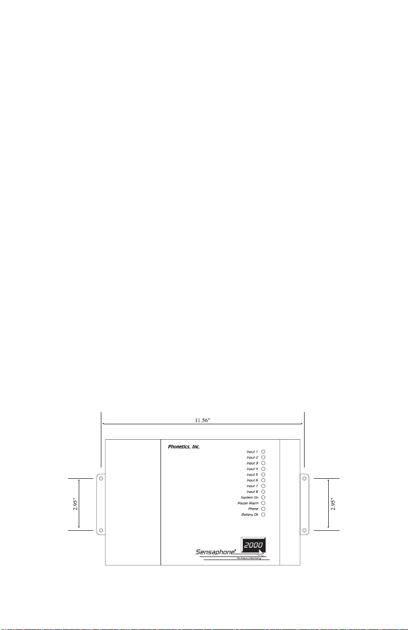
When you receive the unit, carefully remove it from the box.
Mounting tabs with holes are provided on the left and right sides of
the enclosure (see figure below). Mount the unit in a position that
allows easy access to the input terminal block, battery compartment, on/off switch and the programming port. Also, there must be
a power outlet and telephone jack close to the unit.
Chapter 2: Installation
CAUTION:The CPP Monitor 2000 is a sensitive electronic device. Personnel and
work area should be grounded before coming into contact with this device. Do
not install the CPP Monitor 2000 near strong electrostatic, electromagnetic,
magnetic or radioactive fields.
mounting dimensions
21
Page 22
CPP Monitor 2000 User’s Manual
POWER SURGE PROTECTION
The CPP Monitor 2000 can be damaged by power surges and
lightning through the telephone line and the power supply. Although
the unit has built-in surge protection, we strongly recommend that
additional protection be obtained for the unit and for any electronic
equipment that is attached to your power supply and telephone lines.
Power surge protection is especially important if you live in a
lightning-prone area.
BATTERY BACKUP
The CPP Monitor 2000 has a compartment for 6 “C” cell NickelCadmium rechargeable batteries (not included). Be sure to use
quality batteries that are rated for at least 2200mAhr. These will
provide approximately 10-15 hours of unit operation in the event of
a power failure.
NOTE: Use ONLY Nickel-Cadmium rechargeable
batteries.
The unit will constantly recharge the batteries whenever the power
switch is turned on and the unit is plugged into a power supply.
Also, a 3V lithium battery is included for memory storage, to retain
user programming. This battery should provide at least 2 years of
service without power, and up to 10 years of intermittent use.
Turning the CPP Monitor 2000 on
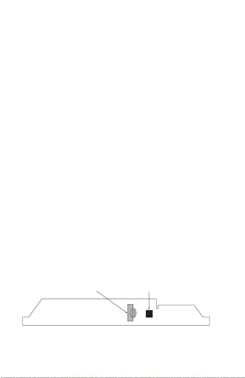
Thread the power supply cord through the strain relief ring next to
the power jack, and plug it in. Then plug the transformer into a
115VAC 60Hz outlet. The ring anchors the cord, protecting the plug
and jack. Slide the power switch to ON to start the unit. The
System-On LED should glow steadily.
Strain Relief
Support Ring
CPP Monitor 2000 Rear View
22
Electrical Jack
Page 23
It is important to note that when the unit is turned off, all programming is retained in non-volatile memory via the internal 3V lithium
battery. The “C” cell Ni-Cad batteries are not in use when the power
switch is off.
TELEPHONE LINE
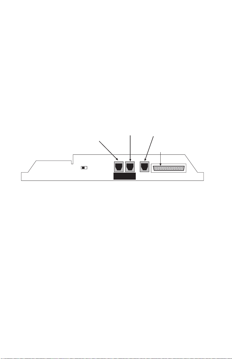
Connect the CPP Monitor 2000’s PHONE LINE jack to a standard 2
wire analog phone line. The unit dials using pulse or tone, with loop
start only. The CPP Monitor 2000 will recognize ringer frequencies
from 16 to 60 Hz and will operate with all standard analog telephone systems that accept pulse or tone dialing.
Chapter 2: Installation
Phone Line:
Attach standard
phone line here.
Power Off/On
Phone Ext. is the
“Line Seize” jack
for use with other
phone devices.
Phone
Phone
Line
Ext.
To record messages, plug a
telephone directly into this jack.
DO NOT connect a Phone Line
to this jack.
RS232 for data communication
Voice
Record
RS232 Port
CPP Monitor 2000—Front View
CAUTION: Do NOT connect the unit’s VOICE
RECORD jack to a live telephone line as this will
cause permanent damage to the unit.
Certain private telephone systems and public switching equipment
may not accept the unit’s dialing or may generate an unacceptable
ring signal. In those cases, a dedicated line may be required for the
unit. Consult the supplier of your telephone system if you encounter
problems.
CAUTION: Never install telephone wiring during a
lightning storm. Never install telephone jacks in wet
locations unless the jack is specifically designed for
wet locations. Never touch uninsulated telephone
wires or terminals unless the telephone line has been
disconnected at the network interface. Use caution
when installing or modifying telephone lines.
23
Page 24
CPP Monitor 2000 User’s Manual
Line Seizure
Line seizure gives the 2000 unit the ability to “seize” the telephone
line when it needs to dial out. For example, if an emergency occurs
which puts the 2000 in alarm mode, the unit will be able to dial out
even if a telephone has been left off the hook. To the right of the
PHONE LINE jack is another labeled PHONE EXT. This jack can
be used to share a phone line with other devices (telephone, fax
machine, modem) and to give the 2000 priority in the event of an
emergency. To make use of this feature you must have all the
extension devices originate from the PHONE EXT. jack. Whenever
the unit must make an alarm phone call, the unit will disconnect any
current phone calls and seize the line for its own use. The unit will
continue to seize the line until the alarm has been acknowledged.
INPUT CONFIGURATION
The CPP Monitor 2000 can accept analog and digital inputs over the
range 0-5VDC. It can also accept current from 4-20mA transducers.
The input load for current transducers is 220 Ohms.
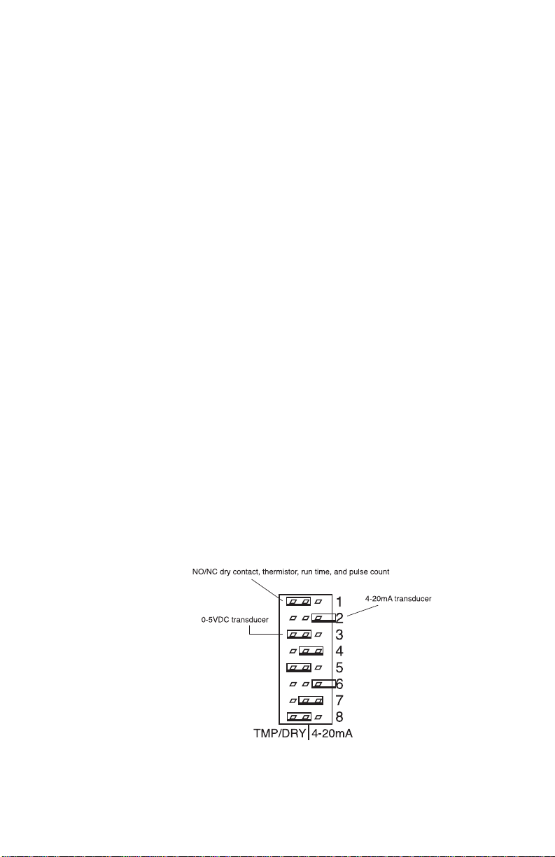
To set the input configuration, adjust the jumpers located just below
the terminal block. Needlenose pliers are recommended for moving
shunts. There is one for each input so that each input can be
individually configured. For thermistors, N.O./N.C.(normally open/
normally closed) dry contacts, run time and pulse count, set the
jumper to the left (marked TMP/DRY). For current transducers set
the jumper to the right (marked 4-20mA). For 0-5VDC transducers,
remove the jumper or simply hang it off one pin for storage purposes. See the figure below.
24
Page 25
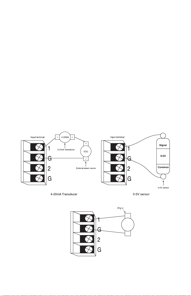
WIRING SENSORS AND TRANSDUCERS
Thermistors: The unit will accept 2.8K and 10K thermistors. These
should be wired to an input terminal and the adjacent ground
terminal. For compatible thermistors check the thermistor data in
the appendices.
Dry Contacts:Only contacts which have no voltage or current
applied may be used. Connect the contact to an input terminal and
an adjacent ground terminal. Do NOT try to monitor a contact that
switches 120VAC. This will permanently damage the unit.
4-20mA: A 4-20mA transducer requires you to have an external DC
power supply for the transducer. Make sure the input is configured
for 4-20mA.
Connect the positive wire of your transducer to the positive terminal
of your DC power supply. Connect the negative terminal of the
transducer to an input terminal on the CPP Monitor 2000. Connect
the negative terminal from your power supply to the adjacent
ground terminal on the 2000.
Chapter 2: Installation
25
Page 26

CPP Monitor 2000 User’s Manual
LED INDICATORS
The LEDs provide on-site alarm and status information. Listed
below are descriptions of how the LEDs work.
Inputs 1-8 and Power:
LED Off: Input OK
LED Blinking: Unacknowledged alarm exists
LED On: Acknowledged alarm exists
Battery:
LED On: Battery condition OK
LED Blinking: Battery condition low
LED Off: Battery very low
System-On:
LED On: System power on
LED Off : System power off
26
Phone:
LED On: Unit is communicating on the phone line
LED Off: Unit is not using the phone line
Page 27

Chapter 3: Communications
This section describes how to install and configure the CPP Monitor
2000 Windows Software for your computer and modem.
Installing and Starting the Software
Minimum requirements
486 or better computer (Pentium recommended)
4 MB of free disk space
4 MB RAM (8 MB RAM recommended)
Graphics card compatible with Microsoft Windows 3.1, 95
or NT (such as VGA)
Microsoft Windows 3.1, 95 or NT
VGA or Super VGA monitor
Mouse
Modem
Chapter 3: Communications
INSTALLATION
The Manager 2000 Windows software setup program makes
installation quick and easy. You’ll be prompted to insert the installation disks in the order they are numbered. Make sure that all
Windows applications are closed before attempting to run Setup. If
you encounter problems during installation, please call CPP
Technical Support at (800)797-7782.
The CPP Monitor 2000 Software for Windows will install to a
directory named C:\S2000, unless you choose to change the
directory name.
WINDOWS ‘95 INSTALLATION
1.Start Windows.
2.Insert disk labelled CPP Monitor 2000.
3.Select Start>Run and type in a:\Setup.exe. Click OK.
4.Follow the prompts until the installation is finished.
27
Page 28

Sensaphone® 2000 User’s Manual
5.Insert disk 1 of the CPP Monitor 2000 Database.
6.Select Start>Run and type a:\Setup.exe and click OK. This will
install the Borland Database Engine.
7.Follow the prompts and install disk 2 when instructed.
8.Follow the prompts until installation is complete.
WINDOWS 3.1 INSTALLATION
1.Start Windows.
2.Insert disk 1 labelled Sensaphone 2000.
3.Select File>Run and type in a:\Setup.exe. Click OK.
4.Follow the prompts until the installation is finished.
5.Insert disk 1 of the CPP Monitor 2000 Database.
6.Select File>Run and type a:\Setup.exe and click OK. This will
install the Borland Database Engine.
7.Follow the prompts and install disk 2 when instructed.
8.Follow the prompts until the installation is complete.
Running the Software
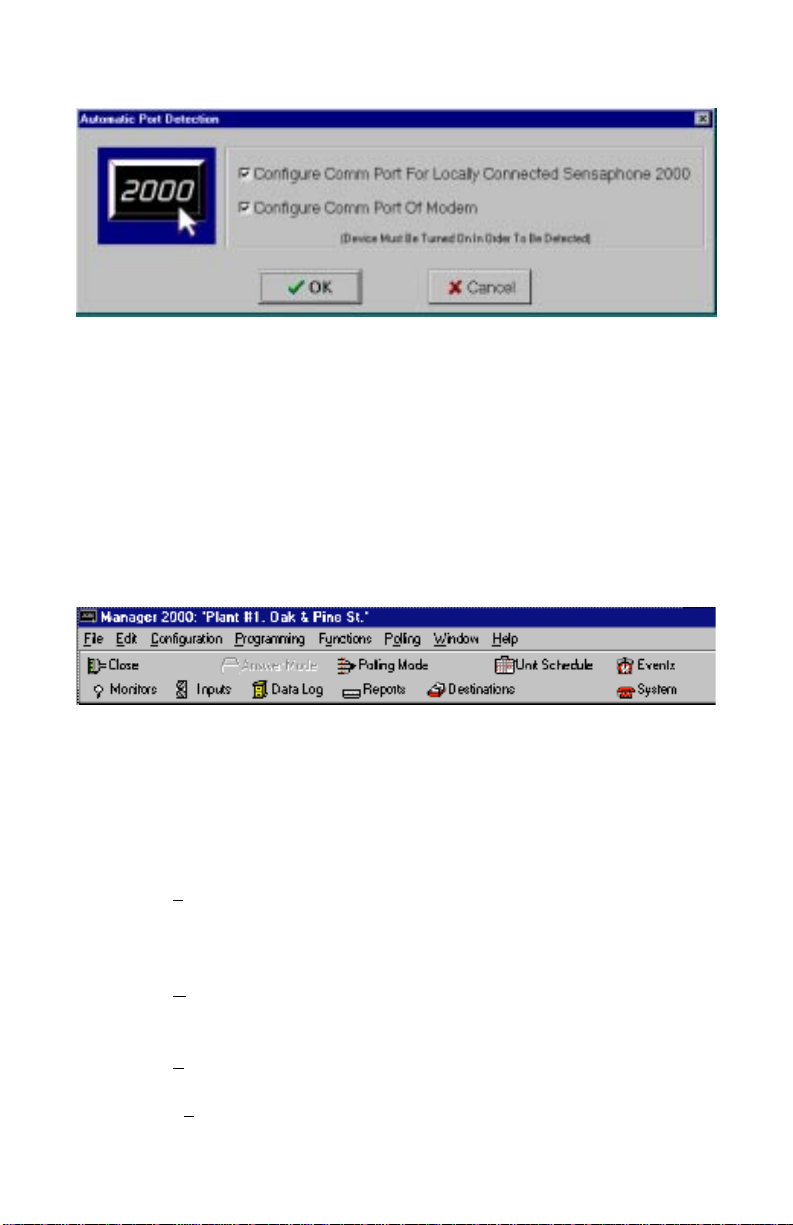
To run the software, double click the 2000 icon. When the software
runs for the first time a configuration screen will appear. This will
automatically configure your modem settings and local serial port if
selected. If you have an external modem, make sure it is ON before
you proceed. If you would prefer to configure the software manually, you may do so after installation. When you start the software
you’ll see the main menu and toolbar. These menus and tools will
allow you to open new 2000 units, communicate with existing 2000units, observe real-time input values and numerous other features.
Pictured below is the Automatic Port Detection form.
28
Page 29
AUTOMATIC PORT DETECTION SCREEN
CPP Monitor 2000 Menu Bar
The menu bar at the top of the window lists menu commands for
selecting a unit, configuring your communication ports, sending
and receiving programming, enabling automatic features and other
functions. You can choose these commands by clicking them with
the mouse. Many frequently used commands are also available as
tools on the Toolbar.
Chapter 3: Communications
The following table briefly describes each menu. Shortcut keys that
you can use to display each menu are included in parentheses next
to the menu names.
Menu name Functions under this menu...
________________________________________________________________________
File (Alt, F) Adding new units, opening units, closing
units, loading data, saving data, deleting
data, printing information, exiting.
________________________________________________________________________
Config (Alt, C) Communications Setup, Communications
Status, Advanced Comm Setup, Options
________________________________________________________________________
Program (Alt, P) Inputs, Destinations, System, Reporting
________________________________________________________________________
Functions (Alt, U) Data Logging, Auto Answer, View Events,
Diagnostics
29
Page 30

Sensaphone® 2000 User’s Manual
________________________________________________________________________
Polling (Alt, O) Unit Schedule, Enable
________________________________________________________________________
Window (Alt, W) Cascade, Tile, Arrange Icons, Minimize all
________________________________________________________________________
Help (Alt, H) About, Help
________________________________________________________________________
Communications Setup
The software will communicate to your 2000 through your
computer’s local serial port or through your modem. These communication paths must be properly configured for a connection to be
established. (If you ran the auto-configure option at start-up, you
may skip over this section.) To configure the communications
settings manually, click on Configuration>Communications Setup.
Local Port Configuration
Select the appropriate serial port to communicate with the 2000.
This must be a serial port on your computer that is unused and can
be connected to the CPP Monitor 2000’s RS232 port.
Modem Setup
Select the serial port that communicates with your modem and
select the maximum baud rate of your modem. This will typically be
all that is required to configure your modem; however, additional
options have been included and are described below.
Retries: This is the number of times Manager 2000 will attempt to
call a CPP Monitor 2000 if it encounters a busy signal or is unsuccessful at making a connection during any manual attempt to call
out.
Use All Dial Time: Checking this box will make the Manager 2000
software wait until this time period has expired before attempting to
communicate with the unit, even though a connection may have
been established earlier.
Dial Time Out: If a modem connection is not established with a
CPP Monitor 2000 before this time expires, Manager 2000 software
terminates the call.
30
Page 31

Modem Setup String: Manager 2000 allows you to enter a setup
string using the AT command set. These are usually only needed if
you are having trouble getting your modem to connect to a CPP
Monitor 2000 unit. See your modem Operator’s Manual for a list of
AT commands supported by your modem. Note that Manager 2000
software will send the “AT” part of the command automatically.
Communication Status
Chapter 3: Communications
The Communication Status screen provides information regarding
communication performance, communication errors and text
descriptions of communication activity in real time. The screen is
useful for troubleshooting communication problems. The parameters for error thresholds and packet timing are adjustable in the
Advanced Comm Setup menu.
31
Page 32

CPP Monitor 2000 User’s Manual
Advanced Comm Setup
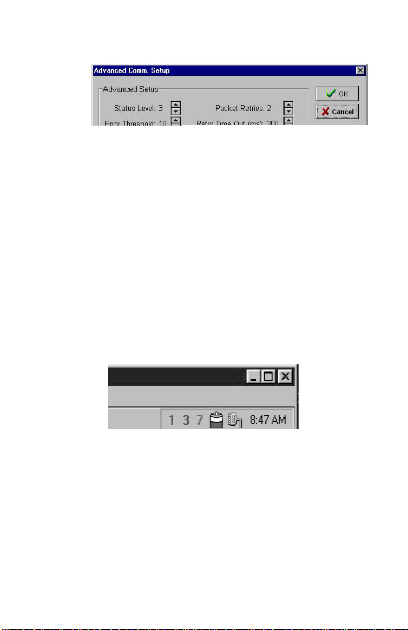
The Advanced Comm Setup form can be used to tune and customize the communication performance of Manager 2000. Typically
you will not need to change these parameters for any reason.
Listed below is a description of each of the parameters on the form:
Status Level: This parameter determines which messages will
appear in the display on the Communication Status form. There are
eight levels of messages:
Level 0:Messaging disabled
Level 1:Adds significant events and errors
Level 2:Adds modem events, writes to unit & file messages
Level 3:Adds packet errors, advanced modem messages,
Level 4:Adds notification of read from unit
Level 5:Adds packet data
Level 6:Adds notification of input status polling
Level 7:Adds polling packet data
Packet Retries: Information flows back and forth between CPP
Monitor 2000 and your PC in data “packets.” Both automatically
check for packet transmission errors. When a bad packet is detected,
it gets sent again. Packet Retries determines how many times a
packet is sent before a communication error is logged.
download messages
Error Threshold: Determines how many consecutive errors will
result in a disconnect.
Retry Time Out: This is the amount of time Manager 2000 will wait
for a response from a CPP Monitor 2000 unit before it decides to
make another request.
Packet Time Out: The amount of time before the PC gives up and
determines that an individual modbus request has timed out.
Decreasing this parameter will not increase performance, but
increasing the parameter may remove occasional errors.
32
Page 33
Options
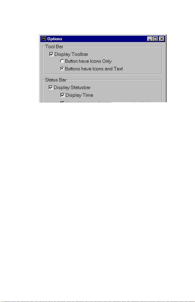
The Options form (under the Configuration menu) allows you to
customize the display to your taste. You can have the Toolbar and/or
the Statusbar be displayed or hidden. You can elect to see the
commands as icons with text or as icons only. The Statusbar can be
placed at the far right end of the Toolbar only if you choose “Buttons have Icons Only” in the Tool Bar box. Otherwise it appears on
the bottom right of your screen.
Chapter 3: Communications
Statusbar (at far right of Toolbar)
The On-Line Timeout, if selected, will automatically disconnect you
from the CPP Monitor 2000 when there is no mouse movement for
the duration of time you specify. The range is 1 minute to 24 hours
and the default, when you turn on this feature, is 1 hour.
33
Page 34
CPP Monitor 2000 User’s Manual
Options screen
34
Page 35

Chapter 4: Programming
The CPP Monitor 2000 software provides access to all of the unit’s
programming through point-and-click menus. The unit can be
programmed either locally through the serial port or remotely via
modem. When you are finished programming, the CPP Monitor
2000 Windows software provides the option to save the unit’s
programming on your computer for backup purposes. You must
save this programming information in order to view the programming off-line for any unit. Once you save the programming for a
particular unit, you may copy the same information into another
unit if desired. A default programming file (defaults.s2k) is
included in case you want to restore the unit to factory default
settings.
SETTING UP NEW UNITS
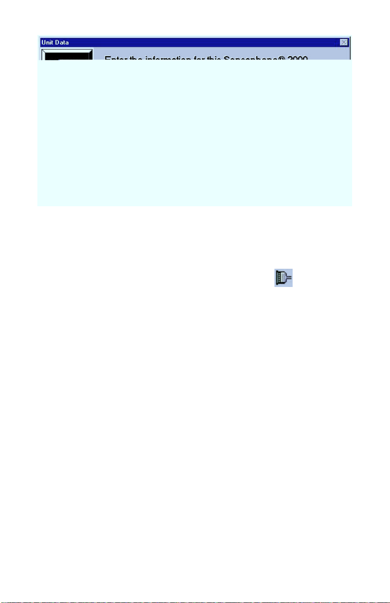
When a new unit is added you will be prompted to fill in a Unit
Data form. This form holds the unit’s description and phone
number as well as password information. CPP Monitor 2000 features
two-level password access: one for programming and one for
status. Status-only access allows you to view input values and
programming but does not allow you to change any parameters.
This is useful if you want to allow multiple users to view the
information for this unit but do not want them to be able to change
anything. If this is the first time the unit is being accessed you
should set up both passwords. When other users add this unit to
their computer you can give them the status password and/or the
programming password depending on your requirements. When
logging in using the status password the software will automatically
send the password during the initial connect sequence. When
logging in using the program password you will be prompted to
enter the password after connecting. You may also allow the
software to automatically log in with the programming password by
clicking the “Save program password to disk” box.
Chapter 4: Programming
Note that if you do not enter a programming password, a default password of “S2000” will be entered
for you.
35
Page 36
CPP Monitor 2000 User’s Manual
Procedure
1. Click the Open button on the Toolbar, then click the
“New” button on the “Open Connection” form. Or, from
the menu bar choose File, then New Unit.
New Unit Data Form
2. Fill in the Unit Description and Phone Number. This sets
up a record that the software will reference whenever you
want to communicate with or check information about
this unit.
3. Enter a status password. If this the first time the unit is
being set up, you must also enter a programming password or you will not be able to program the unit.
4. Select the type of password access you wish to log in
with: status or programming.
* The status password allows viewing access only. No program-
ming changes will be possible. The status password is
automatically saved to your hard disk and will be entered for
you when you attempt to communicate with the unit.
36
Page 37

COMMUNICATING WITH CPP Monitor 2000
This section describes the procedure for communicating with a
CPP Monitor 2000 unit.
Note: the 2000 can only communicate with one person at a time.
This means that if someone is logged on through the RS232 port,
the unit will NOT answer a call, nor will it make any calls until the
connection is closed. Conversely, if someone is on-line using the
modem, you cannot log on through the RS232 port.
Choose Local or Modem communication.
Local Communication
For Local communication you must connect one of your computer’s
serial COM ports to the 2000’s RS232 port.
1. Click the “Open” button on the Toolbar. The “Open Connection”
form will appear.
2. Choose the unit you want to connect with from the text box.
3. Select “Local” Connection Mode.
4. Click “Connect.”
Chapter 4: Programming
Your PC will connect locally to the CPP Monitor 2000 unit. If a
local connection is not established, see the Troubleshooting section
of this manual.
Modem Communication
For Remote communication you must have a modem and a telephone line connected to your computer.
1. Click the “Open” button on the Toolbar. The “Open Connection”
form will appear.
2. Choose the unit you want to connect with from the text box.
3. Select “Modem” Connection Mode.
4. Click “Connect.”
37
Page 38

CPP Monitor 2000 User’s Manual
Your PC will instruct the modem to dial the CPP Monitor 2000 unit
using the phone number from the Unit Data form. The CPP Monitor
2000 will answer the call and establish a connection with your
modem. If a remote connection is not established, see the Troubleshooting section of this manual.
Off-line Communication
Off-line communication provides a method of viewing the programming in a unit without being connected. You can also query, view or
print information from the Data Logger or Event Logger while offline. For Off-line communication you must have a data file saved
for the unit selected. This can only be created after you have
finished programming a unit while on-line and saved the programming. The Manager 2000 software will prompt you to save when
you exit, or you can save by clicking File>Save Data from the menu
bar. A “File Save” box will appear so that you can enter a file name
for that unit. Do not change the .s2k extension because the software
uses this to identify CPP Monitor 2000 data files.
MANAGING UNIT PROGRAMMING FILES
The programming parameters of a CPP Monitor 2000 unit should be
saved to a Data File in your computer. There are several reasons for
this:
1. In order to view a unit’s programming off-line, you need to save the
unit’s programming in a Data File.
2. Once you save the programming for a particular unit, you may copy
the same information into another unit.
3. It’s a good idea to have a backup copy of a unit’s programming in
case the unit gets damaged.
The Manager 2000 Windows software allows you to view saved
CPP Monitor 2000 unit information without being connected to a
unit. You may view a unit’s programming, or view a unit’s downloaded Data Logger or Event Logger. In order to view a unit’s
programming, you need to save the unit’s programming in a Data
File while still on-line.
To create a Data File:
While you are on-line, choose “File” from the main menu, then
select “Save Data.” Enter a file name, then click “OK.”
This will create an Offline Data File.
38
Page 39

Chapter 4: Programming
To view a Data File Off-line:
1. Click the “Open” button on the Toolbar. The “Open Connection”
form will appear.
2. Choose a unit from the text box.
3. Click Edit on the “Open Connection” form. The name of the last
Off-Line Data File that was created or saved appears in the lower left
corner of the Unit Data form. Click “OK” to accept the file or click
the Browse button next to the filename to select another file.
4. Under Connection Mode, select “Off-line.”
5. Click “Connect.”
The Manager 2000 software will display the programming parameters as if you were connected with a unit. You can view these
parameters, but you can’t change them.
To delete a Data File:
Choose “File” from the main menu, then select “Delete Data File.”
Select the file you wish to delete and click “OK.”
To load an existing Data File into a CPP Monitor 2000 Unit:
1. Establish an on-line connection with a CPP Monitor 2000 (either
Local or via Modem).
2. Choose “File” from the main menu, then select “Load Data.”
3. Select the Data File you wish to load, then click “OK.”
The selected Data File will be loaded into the CPP Monitor 2000.
All existing programming in the unit will be overwritten.
SYSTEM PROGRAMMING
The System form includes the global system parameters that apply
to the unit in general. You must be on-line with the unit to program
the System parameters. Once you are on-line, choose Program from
the main menu, then select System. You can also access the System
programming from the Toolbar button labeled System.
Below is a list of the parameters, their default settings and the range
of programming for each parameter.
39
Page 40
Sensaphone® 2000 User’s Manual
System Identification
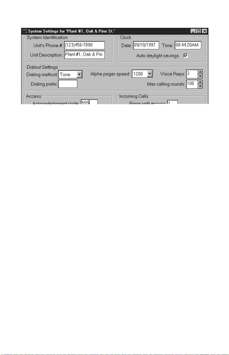
System Settings form
Unit Phone Number:
The Unit’s Phone Number is the identification number of the
CPP Monitor 2000 and can be up to 16 digits long. This is automatically filled in from the information you provided when setting up
the unit on your computer. This number must be programmed to be
the same as the telephone number where the unit is installed. The
Unit’s Phone Number serves several purposes:
1. When using your PC and Manager 2000 software to remotely
2. It’s the first thing spoken by CPP Monitor 2000 during any voice call:
3. When CPP Monitor 2000 sends a cover page with a Fax transmission
Unit Description:
The Unit Description is the text description of the CPP Monitor
2000. It can be up to 32 characters long. This is automatically
40
program a CPP Monitor 2000, this is the number your modem will
dial to contact the unit.
“Hello, this is (Unit Phone Number).”
or alerts an alphanumeric pager, the Unit’s Phone Number is sent as
part of the information.
Page 41

filled in from the information you provided when setting up the unit
on your computer. When CPP Monitor 2000 sends a cover page with
a Fax transmission or alerts an alphanumeric pager, the Unit
Description is sent as part of the basic information.
Clock:
Unit Date & Time
The date and time are automatically programmed into a new unit,
based on your computer’s date and time. This will occur the very
first time you go on-line. If you are in a different time zone you
will need to correct the time accordingly.
Auto Daylight Savings
This instructs CPP Monitor 2000 to automatically correct the time
twice a year for daylight savings.
Programmable settings: On, Off
Default setting: On
Dialout Settings:
Chapter 4: Programming
Dialing Method
The Dialing Method parameter lets you program whether CPP
Monitor 2000 will dial out in Pulse or Tone. The default setting is
Tone.
Dialing Prefix
The “Dialing prefix” box on the System Settings screen is for email
prefixes only. If for instance the 2000 is on an office phone system
where it had to dial a “9” to get an outside line, entering a “9” here
will force the 2000 to dial “9” before dialing the email server phone
number.
To enter a specific prefix for dialout types other than email, go
instead to the Dialout Destination screen (see “Destinations” section
later in this chapter) and enter the prefix with the phone number in
the Destination column, following the instructions under “Special
Dialing Codes.” You must enter each prefix manually for each
individual phone number that requires one.
41
Page 42

CPP Monitor 2000 User’s Manual
Alpha Pager Speed
This is the baud rate of the data connection between CPP Monitor
2000 and your alphanumeric pager service.
Programmable settings: 300, 1200, 2400
Default setting: 1200
Maximum Calling Rounds
The maximum number of times CPP Monitor 2000 will dial through
a list of destinations to attempt to deliver either an alarm or a report.
Programmable range: 0 - 100 calling rounds
Default setting: 100 calling rounds
Voice Repetitions
The number of times CPP Monitor 2000 repeats the alarm message
during a dial out alarm call.
Programmable range: 0-10
Default setting: 3
Access:
Acknowledgment Code
This is the code used to acknowledge an alarm via Touch-Tone
telephone.
Programmable range: 0 - 999999 from 1 to 6 digits long. Note: When
using an acknowledgment code with leading zeros, all digits must be
included. If the acknowledgment code is 000888, simply entering
“888” will NOT acknowledge the alarm.
Default setting: 555
Voice Password
CPP Monitor 2000 allows you to record input and ID voice messages. These messages are protected by the voice password. The
voice password must be entered on a Touch-Tone phone keypad in
order to record voice messages.
Programmable range: 0 - 999999 from 1 to 6 digits long.
Default setting: 555
42
Page 43

Slave ID
This is the modbus address of the CPP Monitor 2000 unit. It is set by
default and should not be changed unless you are using multiple
units that might have the same, and therefore conflicting, ID
numbers. The Slave ID can be set to any number between 1 and
247. It should never be set to “0,” as this will keep you from
communicating with the unit.
Passwords
This command allows you to change CPP Monitor 2000’s programming and status passwords. You can only change these if you are online and have logged on using the programming password.
Incoming Calls:
Rings Until Answer
This is the number of times CPP Monitor 2000 will let the phone ring
before it answers an incoming call.
Programmable range: 1 - 15 rings
Default setting: 1 ring
Chapter 4: Programming
Carrier Wait Time
The Carrier Wait Time is the amount of time CPP Monitor 2000 will
wait for a modem connection when it receives an incoming call.
INPUTS
The CPP Monitor 2000 monitors 8 universal inputs, power, and
battery condition. You must be on-line with the unit to program the
Input parameters. Once you are on-line, choose “Program” from
the main menu, then select “Inputs.” You can also access Input
programming from the Toolbar button labeled Inputs.
NOTE: Do not set this parameter too short, otherwise
a modem connection may never be established.
Programmable range: 10 to 60 seconds
Default setting: 35 seconds
43
Page 44
CPP Monitor 2000 User’s Manual
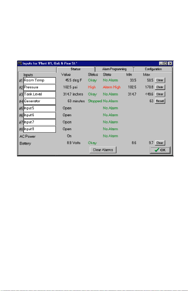
There are 3 tabs on the Inputs form: Status, Alarm Programming,
and Configuration.
Status tab:
The Status tab shows the name, value, units of measure, status,
alarm state, and Min/Max values for all of the inputs.
Listed below is a description of the information found on the Status
tab of the Inputs form:
Input Name:
This field will allow you to type in a 16 character description for
each input.
Value (with units):
This is the real time state or value of each input. If a unit of measure
has been selected for the input, it will also be displayed here. If you
choose Pulse Count or Run Time as your Input Types and double
click on their respective Values, you will pop up a small screen on
which to preset the values for each.
Display range for 0-5V, 4-20mA, and Temperature input types:
-99,999.9 to 99,999.9
Display range for Pulse Count and Run Time: 0 to 999,999. You can
44
Page 45

Status:
State:
Chapter 4: Programming
choose hours, minutes, or seconds for time measurement, under the
Configuration tab. When the limit of 999,999 is reached, the value
will return to zero.
This is the current status of each input with respect to that input’s
alarm programming. For any input that displays a numeric value,
(temperature, 4-20mA, 0-5VDC, pulse count, or time accumulator)
the Status column will display either Okay, High, or Low. For N.O./
N.C. inputs, the Status Column will display either Open, Closed, or
the label selected for that input from the Configuration tab.
The actual alarm state of the input. There are 5 possible alarm
states: No Alarm, Waiting, Alarm, Outstanding, and Cleared.
Definitions:
No Alarm (green) - A digital input is in its normal position or an
analog input is within the programmed alarm limits.
Waiting (yellow) - A digital input is in the alarm position or an
analog input has gone outside of the programmed alarm limits but
the input’s alarm recognition time has not expired.
Alarm, Alarm High, Alarm Low (red) - A digital input has remained
in the alarm position or an analog input has remained outside of the
programmed alarm limits for the length of the alarm recognition
time. An unacknowledged alarm exists.
Cleared (purple) - An alarm has been acknowledged, but the input is
still in the alarm position or is still outside of the programmed alarm
limits.
Outstanding (pink) - An unacknowledged alarm exists but the input
has returned to its normal position or back to within the programmed alarm limits.
Min & Max:
The highest and lowest values an input has reached. Digital inputs
have no Min or Max values, while other inputs may have only a
Max.
45
Page 46

CPP Monitor 2000 User’s Manual
Clear Alarms:
The button marked “Clear Alarms” will, when pressed, clear all set
alarms.
Note: To clear an individual alarm, double click on it
in the “State” column.
Configuration tab:
The Configuration tab shows the name, type, high and low table
values, calibration setting, and label/units for all of the inputs.
Listed below is a description of the information found on the
Configuration tab of the Inputs form:
Input Type:
This can be one of eight types - Normally Open (N.O.), Normally
Closed (N.C.), 0-5V, 4-20mA, 2.8K thermistor, 10K thermistor,
Pulse count or Time Accumulator.
Table Low & Table High:
An important feature that CPP Monitor 2000 offers is the ability to
create a unique linear table for each 4-20mA or 0-5V analog input.
The Table Low & Table High fields are used to define the upper and
lower analog display limits for 4-20mA and 0-5V input types. For
example, suppose you’re using a 4-20mA transducer to measure the
depth of water in a 75 foot well. Simply enter a Table Low of 0, and
46
Page 47
a Table High of 75 and the CPP Monitor 2000 will scale the input to
read between 0 and 75.0. The Table Low & Table High fields are
also used to set the upper and lower limits for the bar and gauge
monitors found on the Monitor form.
Programmable ranges:
Default settings:
Calibration:
To compensate for minor variances in sensor accuracy, an offset
may be programmed for each input. For example, if input #3 is
sensing temperature and is reading 2.5 degrees too high, then the
calibration for input #3 should be set at -2.5 to obtain an accurate
reading. Digital inputs (N.O. and N.C.) cannot be calibrated.
Chapter 4: Programming
Table Low: -99,999.9 to 99,999.9
Table High: -99,999.9 to 99,999.9
Table Low value: 0
Table High value: 100
Programmable range: +/-999.9 units
Default setting: 0.0
Label/Units:
This field lets you identify the input value using specific units of
measure and/or a description of the input condition. Several
selections for dry contacts are listed with an O: or C: next to them
to differentiate the “Open” contact label from the “Closed” contact
label. The label/unit that is selected will also be spoken during a
voice telephone call (except for “Custom”). You may choose from
any of the selections provided or pick “Custom” to create your own
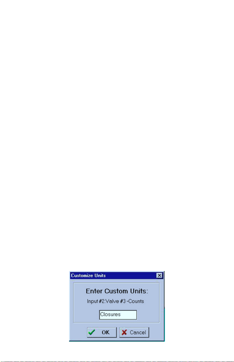
label (except for RunTime and N.O/N.C.). Select “Custom” and a
“Customize Units” box like the one below will pop up.
47
Page 48
CPP Monitor 2000 User’s Manual
Note that for N.O. and N.C. input types, units of NONE will result
in the unit speaking “open” or “closed” during a status report.
Selectable units of measure: none, degrees F, degrees C, inches,
feet, gallons, liters, psi, gpm, volts, amps, hours, minutes, seconds
Default setting: none
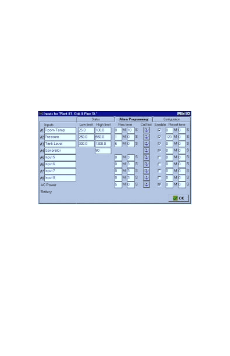
Alarm Programming tab:
The Alarm Programming tab shows the name, high and low alarm
limits, alarm recognition time, call list, dialout enable status, and
alarm reset time for all of the inputs.
Listed below is a description of each of the programming options
found on the Alarm Programming tab of the Inputs form:
Inputs Name:
This field will allow you to type in a 16 character description for
each input.
Alarm Low Limit:
This is the value which will cause the unit to make alarm dialouts
on an input low condition.
0-5V, 4-20mA, and Temperature:
48
Programmable range: -99,999.9 to 99,999.9
Default setting: 0
Page 49

Pulse Count and Run Time Accumulator:
N/A
Alarm High Limit:
This is the value which will cause the unit to make alarm dialouts
on an input high condition.
0-5V, 4-20mA, and Temperature:
Programmable range: -99,999.9 to 99,999.9
Default setting: 100
Pulse Count and Run Time Accumulator:
Programmable range: 0 to 999,999
Default setting: 1,000
Recognition Time:
This is the time required for an out of tolerance condition to become
an alarm. The input must remain above or below the alarm limit
continuously for the entire time in order to become an alarm.
0-5V, 4-20mA, and Temperature:
Programmable range: 0 seconds - 270 minutes, Default setting: Inputs 1-
8: 3 seconds
Chapter 4: Programming
AC Power:
Pulse Count and Run Time Accumulator:
Call List:
Click this button to display the list of destinations the unit will call
to deliver an alarm message for each input. CPP Monitor 2000 will
call the destinations in numerical order. Place a check next to each
destination you want CPP Monitor 2000 to call for an alarm on the
currently selected input.
Programmable range: 0 seconds - 270 minutes, Default setting: 5 minutes
N/A
Default setting: All
49
Page 50
Sensaphone® 2000 User’s Manual
Alarm Enable/Disable:
This will enable or disable the dialout for this input.
Default setting: Enabled
Alarm Reset Time:
The is the time allowed for an acknowledged alarm’s fault condition
to be corrected before the unit resets (reactivates) the alarm and
begins the dialout process all over again. The default setting for this
parameter is 0 minutes and 0 seconds, meaning that the alarm reset
feature is disabled.
Programmable range: 0 min, 0 sec to 270 min, 0 sec
Default setting: 0 min, 0 sec (disabled)
MONITORS
The Manager 2000 software provides the user with the ability to
monitor all of a CPP Monitor 2000’s inputs in real-time graphical
form. You must be on-line with a unit to monitor its inputs. Once
on-line, you can access real-time input monitoring from the Toolbar
button labeled Monitors.
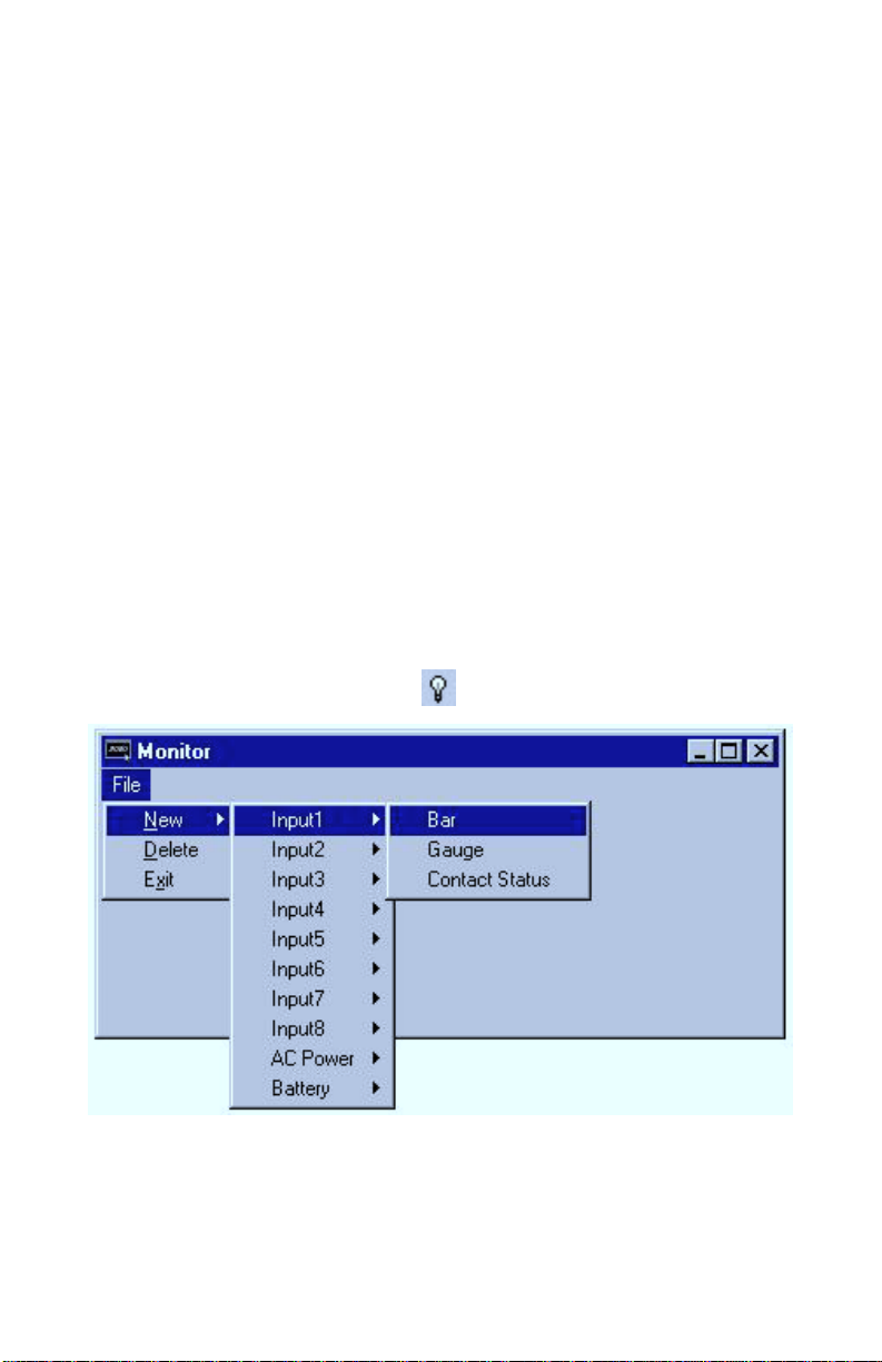
Displaying Input Monitors
To display a monitor, from the Monitor menu choose File>New,
then select the desired input and monitor type. More than one
monitor may be displayed for each input.
50
Page 51

Delete Input Monitors
To delete a monitor, select it by clicking on it. Next, choose
File>Delete from the Monitor menu.
There are 3 types of input monitors: Bar, Gauge, and Contact
Status. Below is a view of each and an explanation of its features.
Bar Reading:
This is the real-time value of the input. This number is white if the
input status is OK, but will change to red if the input goes above or
below the programmed alarm limits.
Chapter 4: Programming
bar monitor
Low Limit:
The lowest possible reading of the monitor. This is taken from the
Table Low field on the Configuration tab of the Inputs form.
High Limit:
The highest possible reading of the monitor. This is taken from the
Table High field on the Configuration tab of the Inputs form.
Low Alarm Limit:
(lower red zone) The low alarm limit for this input. This is taken
from the Low Limit field on the Alarm Programming tab of the
Inputs form.
51
Page 52
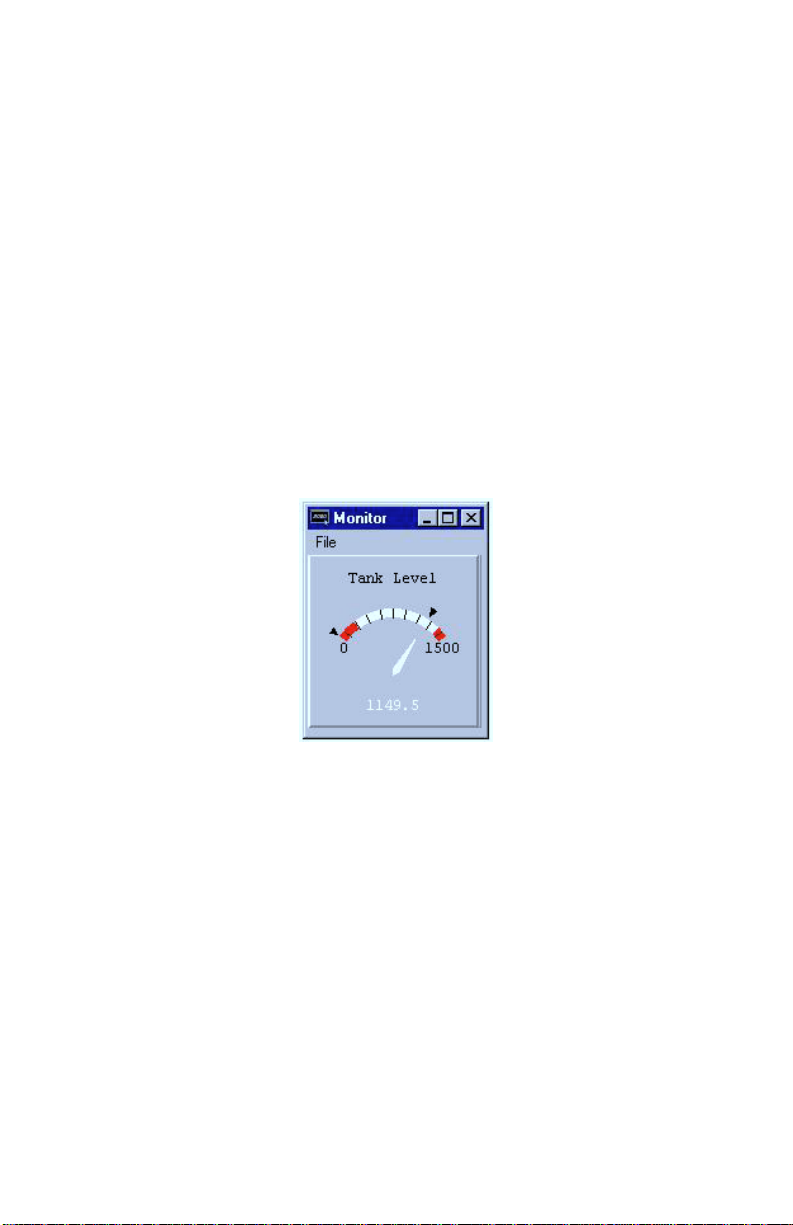
CPP Monitor 2000 User’s Manual
High Alarm Limit:
(upper red zone) The high alarm limit for this input. This is taken
from the High Limit field on the Alarm Programming tab of the
Inputs form.
Minimum Input Reading:
(lower black triangle) This is the lowest value reached by this input.
This is taken from the MIN field on the Status tab of the Inputs
form.
Maximum Input Reading:
(upper black triangle) This is the highest value reached by this
input. This is taken from the MAX field on the Status tab of the
Inputs form.
Gauge Reading:
This is the real-time value of the input. This number is white if the
input status is OK, but will change to red if the input goes above or
below the programmed alarm limits.
Low Limit:
The lowest possible reading of the monitor. This is taken from the
Table Low field on the Configuration tab of the Inputs form.
52
gauge monitor
Page 53
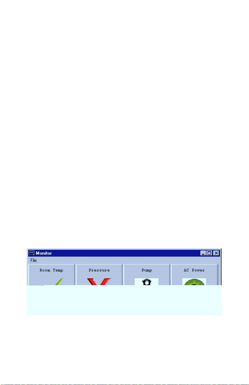
High Limit:
The highest possible reading of the monitor. This is taken from the
Table High field on the Configuration tab of the Inputs form.
Low Alarm Limit:
(lower red zone) The low alarm limit for this input. This is taken
from the Low Limit field on the Alarm Programming tab of the
Inputs form.
High Alarm Limit:
(upper red zone) The high alarm limit for this input. This is taken
from the High Limit field on the Alarm Programming tab of the
Inputs form.
Minimum Input Reading:
(lower black triangle) This is the lowest value reached by this input.
This is taken from the MIN field on the Status tab of the Inputs
form.
Chapter 4: Programming
Maximum Input Reading:
(upper black triangle) This is the highest value reached by this
input. This is taken from the MAX field on the Status tab of the
Inputs form.
contact status monitor
The Contact Status monitor displays a different graphic depending
on the Label/Units selected for a particular input. The displayed
graphics are as follows:
53
Page 54
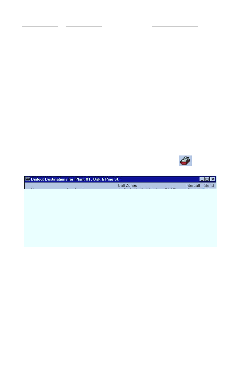
CPP Monitor 2000 User’s Manual
Input Label/Units Input OK graphic Input ALARM graphic
none [check mark] [red X]
OK/Fault [check mark] [red X]
On/Off [Light Bulb - ON] [Light Bulb - OFF]
Running/Stopped [Traffic Light - GREEN] [Traffic Light - RED]
AC Power [Light Bulb - ON] [Light Bulb - OFF]
DESTINATIONS
CPP Monitor 2000 will call up to 32 telephone numbers or E-mail
addresses (both referred to as destinations) to report alarm conditions or send reports. Destinations can be voice calls, fax machines,
computers with modems running CPP Monitor 2000 software, Email addresses, numeric pagers, or alphanumeric pagers. You must
be on-line with the unit to program the Destination parameters.
Once you are on-line, choose Program from the main menu, then
select Destinations. You can also access the Destination programming from the Toolbar button labeled Destinations.
54
Dialout Destinations form
The Dialout Destinations form allows you to program information
for up to 32 destinations. The parameters and their options are listed
below:
Name:
This field allows you to program a description (16 characters max)
for each destination. The name will appear on faxes and E-mail
transmissions whenever an alarm or report is sent to the destination.
If you are entering a fax destination be sure to use the name of
person who you intend to receive the fax.
Page 55

Destination:
The actual telephone number or E-mail address CPP Monitor 2000
dials to deliver its report or alarm message. The Destination field
can be up to 64 characters long for E-mail addresses and 32 digits
for all other Dial Types and may consist of numbers, letters, and
special dialing codes.
Numeric Pagers
The CPP Monitor 2000 can send alarm messages to numeric pagers.
It will automatically send its telephone number and the alarm input
number when dialing to a numeric pager. All you have to do is
enter the telephone number of your pager.
Example: (310)565-2300
Note: If your pager service is answered by a voiceprompted message you will need to enter additional
programming. See the Special Dialing codes section
below.
Alphanumeric Pagers
The CPP Monitor 2000 can dial alphanumeric pagers to send alarm
messages. The CPP Monitor 2000 will send the unit description,
telephone number, input name and input value. To program an
alphanumeric pager destination, enter the phone number followed
by the letter A and then the pager ID.
Chapter 4: Programming
Example: 1-610-555-4593 A 0504099
E-mail
The CPP Monitor 2000 can send alarm messages and reports via E-
mail. For this to work you must have an internet E-mail account
and register the unit with Crucial Power. The unit will automatically
dial a toll-free number to the E-mail server at Phonetics and then
forward the information to you. A monthly fee is required to
receive E-mail from your CPP Monitor Simply fill out the E-mail
registration card that came with your unit, or contact Phonetics for
more details. In the “Destination” field, enter the E-mail address.
Example: [email protected]
55
Page 56

CPP Monitor 2000 User’s Manual
Special Dialing Codes:
Sometimes, when dialing out on certain phone systems, CPP Monitor
2000 may need special instructions to access an outside phone line,
to contact numeric pagers, or to use alphanumeric pager services.
The following dialing codes give CPP Monitor 2000 instructions on
how to send the phone digits when dialing the phone number. Each
code is counted as one digit toward the total of 32 digits. The
dialing codes are:
P = two-second pause. A two-second pause can be placed anywhere
within the phone number by typing the letter P (upper or lower
case). The pause takes up one digit and may be used more than
once. This is typically required when a pager service is answered by
a voice prompted message. You must add enough pauses to get past
the voice message. In this case you must enter the number you wish
to be displayed on your pager.
Example: 555-2233 PP 444-8877#
POUND (#) or ASTERISK (*): When dialing to a numeric pager, a
pound sign (#) or an asterisk (*) may be used within the phone
number. An asterisk (*) typically is displayed as a dash (-) on most
pagers.
Example: 1 # 6105554591 PP 986033 #
W = wait for answer. This code instructs CPP Monitor 2000 to wait
until the call is answered before continuing. The “W” code takes up
one digit and may be used only once. The “W” code is typically
used in the middle of a dialout number when calling a numeric
pager. The CPP Monitor 2000 will wait for the pager company to
answer the call before sending the number to be displayed on the
pager. Note that the 2000 automatically waits for the call to be
answered after the last digit in the telephone number is dialed.
Example: 1-610-555-4593 W 610-558-2000
(pager company phone #) W (number to display on numeric pager)
Note that digits following “W” to numeric pagers will
automatically be dialed as touch-tones.
I= send alarm input #. This code instructs CPP Monitor 2000 to send
the input numbers that have an alarm to a numeric pager. The “I”
code takes up one digit and may be used only once in the phone
number. Note that this is only required if you must insert additional
dialing codes (such as pauses) to make your pager work.
Example: 555-2233 PP 444-8877 I
56
Page 57

Special Alphanumeric Pager Dialing Codes
A = alphanumeric pager ID (required)
C = alphanumeric character password (optional)
A = alphanumeric pager ID: The “A” dialing code is used ONLY
for alphanumeric pager destinations. It is placed between the pager
company’s telephone number and a particular pager’s ID number by
typing the letter A (upper or lower case). It instructs CPP Monitor
2000 to wait until a connection is made to the alphanumeric pager
service’s computer system before transmitting the ID number for a
particular pager.
Example: 1-610-555-4593 A 0504099
C = alphanumeric character password: The “C” dialing code is
used ONLY for alphanumeric pager destinations and only if your
particular pager system requires a character password. This
password may be required for CPP Monitor 2000 to access the pager
service’s computer system. If required, it is placed between the
pager company’s telephone number and the required character
password in the dialout sequence by typing the letter C (upper or
lower case). The character password must precede the pager ID
number.
Chapter 4: Programming
Example if character password required:
1-610-555-4593 C 000000 A 0504099
(pager company phone #) C (character password) A (pager ID #)
The alphanumeric character password is optional and is, in general,
reserved for future services. Length of the password, when used,
may be different in some systems. Consult your pager service for
more information.
Call Zones:
CPP Monitor 2000 is capable of assigning different destinations to
specific calling groups (zones) to accommodate work shift schedules. There are 4 Call Zones to choose from. To include a destination in a Call Zone, check the appropriate box. To set up Call
Zones, click on the “Edit Zones” button and the following form will
appear:
57
Page 58
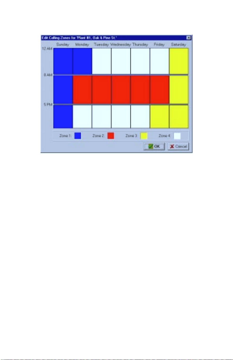
CPP Monitor 2000 User’s Manual
The Edit Calling Zones form divides up the 7 day week into 21
blocks of time. To change the start and end time for each block,
drag the horizontal divider bars up or down as needed. To reassign
a block of time to a different Call Zone, click inside the block until
it matches the color of the desired zone. To change the color of a
zone, double click on the zone’s color square at the bottom of the
form. Select a new color from the palette, then click the OK button.
edit zones form
Alarm Call Mode:
The three selections for destination Alarm Call Mode are Disabled,
Until Acknowledged, and Inform.
Disabled:
Destinations programmed with Alarm Call Mode Disabled will
never be called. This is simply a way to disable dialing to this
destination if necessary.
Until Acknowledged:
Destinations programmed with Alarm Call Mode “Until Acknowledged” will continue to be called until one of them acknowledges
58
Page 59

Inform:
Chapter 4: Programming
the alarm. Once acknowledged, the remaining destinations will not
be called.
Example: An alarm occurs and the CPP Monitor 2000
is programmed to call destinations #1,#2, and #3 and
all 3 destinations are Alarm Call Mode “Until
Acknowledged.” The unit will call destination #1, if
the alarm isn’t acknowledged, it will call #2. If
destination #2 doesn’t acknowledge, then the unit will
call destination #3. If the alarm still hasn’t been
acknowledged, CPP Monitor 2000 will call destination
#1 again. This process will continue until one of the
destinations acknowledges the alarm.
Note: Fax and E-mail destinations cannot be pro-
grammed as “Until Acknowledged” call modes.
Destinations programmed with Alarm Call Mode “Inform” will be
called until the alarm message has been successfully delivered one
time, regardless of acknowledgment. If a transmission to an
“Inform” destination was successful, that destination will not be
contacted again. CPP Monitor 2000 will only make additional
attempts to contact an Alarm Call Mode “Inform” destination if that
destination hasn’t successfully received its transmission (for
example, due to a “no answer,” “busy signal,” “no carrier” response). If a transmission fails to reach a destination after the last
calling round is completed, the failure is recorded in the Event Log.
Calls to priority “Inform” destinations are useful for providing
records of alarm events.
Example: The CPP Monitor 2000 used in the above
example is monitoring the heating system in a school.
The first three destinations are set as Alarm Call
Mode “Until Acknowledged” and programmed to call
maintenance personnel. In addition, destination #4 is
programmed to call the school’s fax machine and is
set as Alarm Call Mode “Inform.” CPP Monitor 2000
will call the maintenance personnel as described
above so that they can fix the boiler, and will also
send a fax to the school office informing them of the
problem.
Important: Destinations programmed as Alarm Call
Mode “Inform” cannot acknowledge alarms.
59
Page 60

CPP Monitor 2000 User’s Manual
Dial Type:
This is used to specify the type of call CPP Monitor 2000 will make
to a particular destination. The available dialout types are: Fax,
Voice, E-mail, Pager, Alpha Pager, and Modem.
Fax
- This instructs CPP Monitor 2000 to send a fax transmission to
either a fax machine or a PC with the ability to receive a fax
directly.
E-mail
- This instructs CPP Monitor 2000 to deliver a message to
the E-mail address programmed in the destination field.
NOTE: For “E-Mail” Dial Types, only E-mail
addresses may be programmed in the destination
field, NOT telephone numbers. CPP Monitor 2000 is
pre-programmed with a toll-free 800 number that will
automatically connect to Phonetics’ E-mail server
system. Note: E-mail service requires a subscription
fee.
Numeric Pager
- This instructs CPP Monitor 2000 to dial a
numeric pager and leave the unit’s ID number and alarm input
numbers on the display. This will happen automatically just by
entering the pager’s telephone number in the destination field. If
you want to change the information that is sent to your pager or you
are having trouble receiving the page, you may use the special
dialing codes to customize the dialout to your pager.
NOTE: When dialing to a numeric pager it is sometimes necessary to combine codes. Certain pager
systems vary and you must adjust accordingly. To test
your pager system, use an extension telephone on the
same line as the CPP Monitor 2000 unit and listen
in during the CPP Monitor 2000’s dial-out to confirm
that your pager service is reached without a problem.
If you must add a pause, use the letter P to insert a
two second pause wherever necessary.
Alpha Pager
- This instructs CPP Monitor 2000 to deliver a text
message to an alphanumeric pager.
Modem
- This instructs CPP Monitor 2000 to call a modem
attached to a computer running Manager 2000 software.
60
Page 61

Intercall Delay:
The intercall delay is the amount of time CPP Monitor 2000 will wait
after completing a call before calling the next destination. The delay
is in seconds, with a default of 30.
Note: A 30-second delay is too short to allow a call
back if a pager is being called. Increase the delay
time enough to accommodate your pager.
Send Report:
CPP Monitor 2000 can be programmed to automatically send reports
to selected destinations. Check this box to include this destination
when sending reports.
Note: Reports may only be sent to Fax or E-mail
destinations.
DATALOGGING
CPP Monitor 2000’s built-in Data Logger can log and store information on all 8 universal inputs, AC power and backup battery voltage.
You must be on-line with the unit to program the Datalogging
parameters. Once you are on-line, choose “Functions” from the
main menu, then select Data Logging. You can also access the Data
Log programming from the Toolbar button labeled Data Log.
Chapter 4: Programming
Note that whenever you change any parameters on the Data Log
form the datalogger in the CPP Monitor 2000 will be reset. If you
need to make changes to your programming, be sure to “Retrieve
Data” first.
61
Page 62
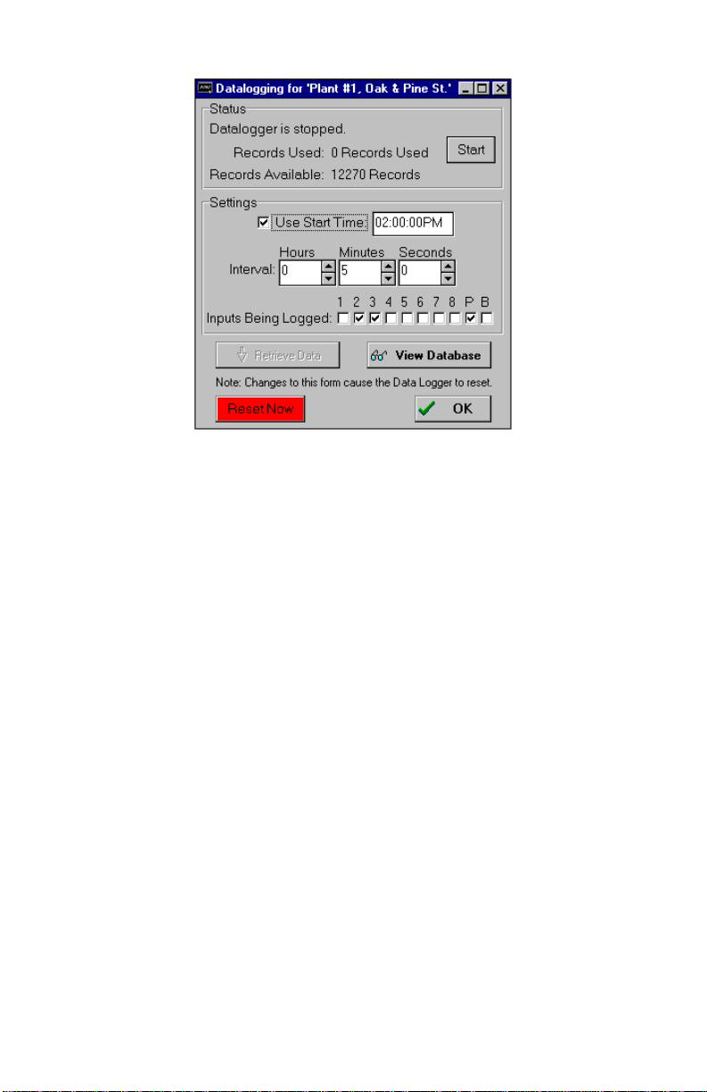
CPP Monitor 2000 User’s Manual
Below is a list of Data Log programming parameters, their default
settings and the range of programming for each parameter.
data log form
Interval:
Time between data logs.
Programmable range:
Minimum: 0 hours, 0 minutes, 1 second
Maximum: 199 hours, 59 minutes, 59 seconds
Default Setting:
0 hours, 0 minutes, 10 seconds
Warning
Setting the Data Logger interval to just a few seconds will produce
large amounts of data. If you download this data regularly you will
quickly begin to fill your hard disk. Care must be taken to evaluate
your system and needs to avoid this situation.
62
Page 63

Use Start Time:
Checking this box will make the CPP Monitor 2000 start its Data
Logger at the time indicated in the Start Time box. If this box is not
checked, Datalogging will begin immediately.
Start Time:
CPP Monitor 2000 can be programmed to begin Datalogging at a
particular time of day. When CPP Monitor 2000’s internal clock
reaches the programmed Start Time, the unit will begin Datalogging
the selected input values at the programmed interval. The Start
Time function is used to delay the start of Datalogging. Once
Datalogging has begun, the Start Time programming is ignored.
Default Setting: 12:00:00AM
Inputs Being Logged:
This selects which inputs CPP Monitor 2000 will log. The unit’s data
logger can store 32,768 samples. Every time the unit logs input
data, it uses one sample for each checked box. For example, if
inputs 1-5 are selected, 5 samples are used up every time CPP
Monitor 2000 logs data. The more inputs you select, the fewer
samples are left available. Below is a table showing the number of
Data Samples available vs. the number of Inputs Being Logged.
Once the CPP Monitor 2000 has filled its Data Logger, it will begin
overwriting the oldest Data Log samples with new ones.
# of Inputs Being Logged Data Samples Available
1 32,768
2 16,384
3 10,922
4 8,192
5 6,553
6 5,461
7 4,681
8 4,096
9 3,640
10 3,276
Chapter 4: Programming
Start/Stop datalogging:
To start Datalogging, click on this button.
Default setting: Stopped
NOTE: Any changes to the Data Log Programming
form will RESET the datalogger.
63
Page 64
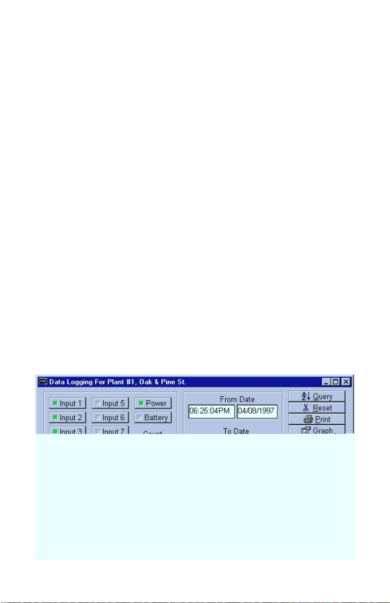
CPP Monitor 2000 User’s Manual
RESET NOW Button
This button will reset the Data Logger (i.e., delete the records) in
the 2000. If the Data Logger was just received, a RESET within 5
minutes of downloading will only delete the records just downloaded. The 2000 will retain any data that was logged during the
download period. After 5 minutes have passed since the download,
clicking the RESET button will delete ALL records in the 2000.
Downloading the Data Logger:
To view a CPP Monitor 2000’s Data Log samples, the unit’s Data
Logger must first be downloaded to your PC. You must be on-line
with a unit to download its Data Logger. Once you are on-line,
choose “Functions” from the main menu, then select Datalogging.
You can also access the Data Logger from the Data Log Toolbar
button.
To download the Data Logger, click “Retrieve Data.”
Every time a unit’s Data Logger is downloaded, the Manager 2000
software adds the new information to that unit’s database in your
PC. It also checks for and filters out duplicate Data Log records.
Viewing the Data Logger (on-line):
Once the Data Logger has been downloaded, it can be viewed. To
view the Data Logger, click the “View Database” button on the Data
Log Programming form. The following form will appear.
64
Page 65

Viewing the Data Logger (off-line):
To view a unit’s downloaded Data Logger off-line, follow the
instructions for “Offline Communication” and “To View A Data File
Offline” earlier in this chapter.
Below is a list of programming parameters for viewing the Data
Logger:
Input selection:
You must choose which inputs to display. To display a Data Log
record for an input, click on the input’s button to highlight it.
From Date and To Date:
Selects a range of Data Log records by time.
Query:
Searches the Data Log database and displays the information that
corresponds to the selected time period and selected inputs.
Chapter 4: Programming
Graph:
Once the Data Log records have been displayed, they may be viewed
in graph form by clicking the “Graph” button. The graph will show
all inputs selected in the query. If too many samples are selected for
graphing, the software gives you the option to average values.
Otherwise, you will have to perform a smaller query to avoid
averaging. The graph has many features that allow you to display
the data graphically, including line graphs, bar charts and threedimensional views. Experimentation is the best way to learn about
all of the available options. A sample graph follows.
65
Page 66
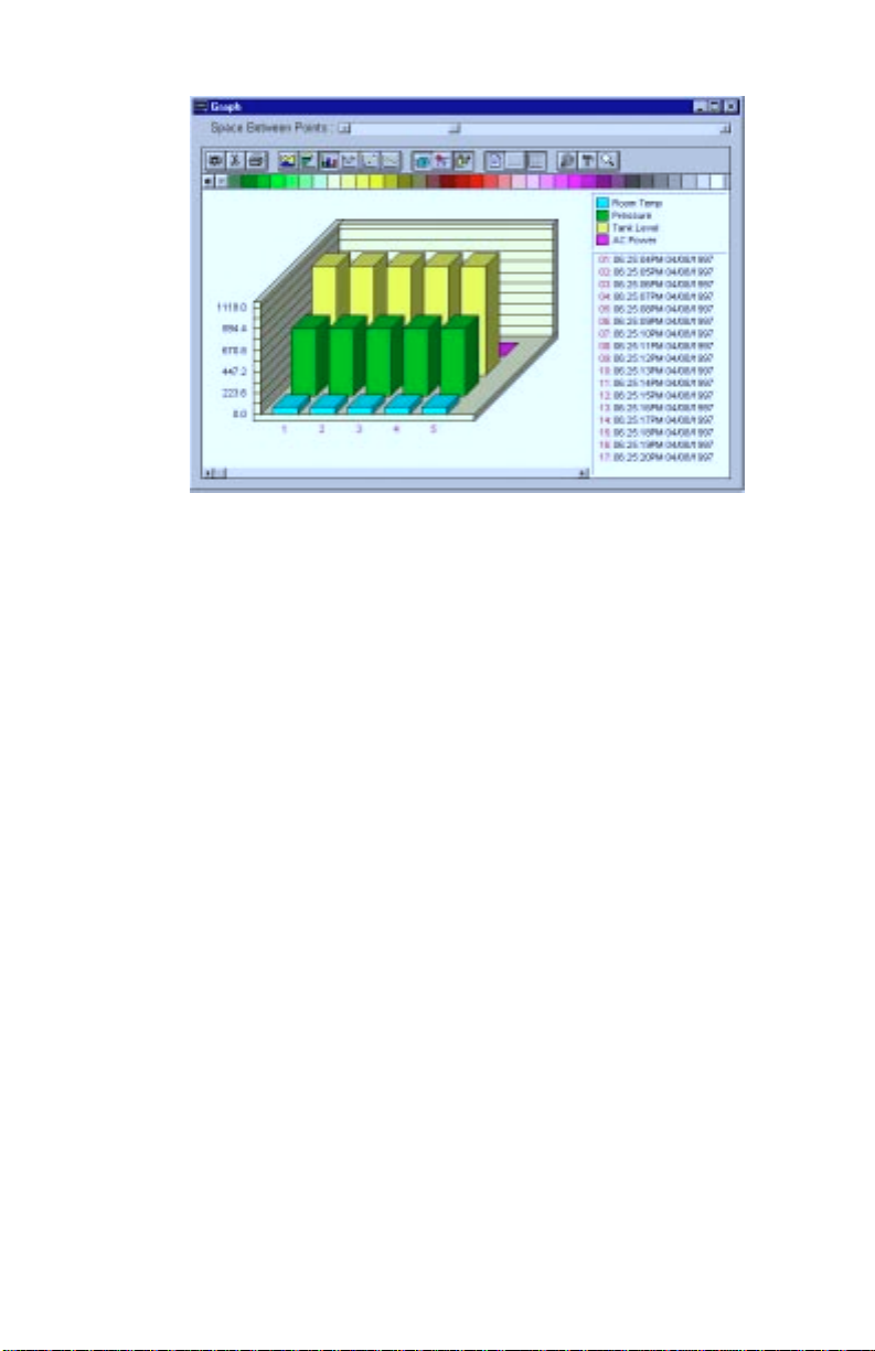
CPP Monitor 2000 User’s Manual
Reset:
Deletes Data Log records for the current CPP Monitor 2000 unit
from your PC. It will reset all the information in the database for
the selected unit.
sample graph
Print:
Once the Data Log records have been displayed, they may be printed
by clicking this button.
Export:
Once the Data Log records have been displayed, the displayed
information may be saved as a comma-delimited file. This file can
then be used in a spreadsheet such programs as Lotus 123 or
Microsoft Excel.
EVENT LOGGER
CPP Monitor 2000 keeps track of important system events with its
built-in Event Logger. Each CPP Monitor 2000 unit stores the last
500 system events. System events include alarms, incoming and
66
Page 67
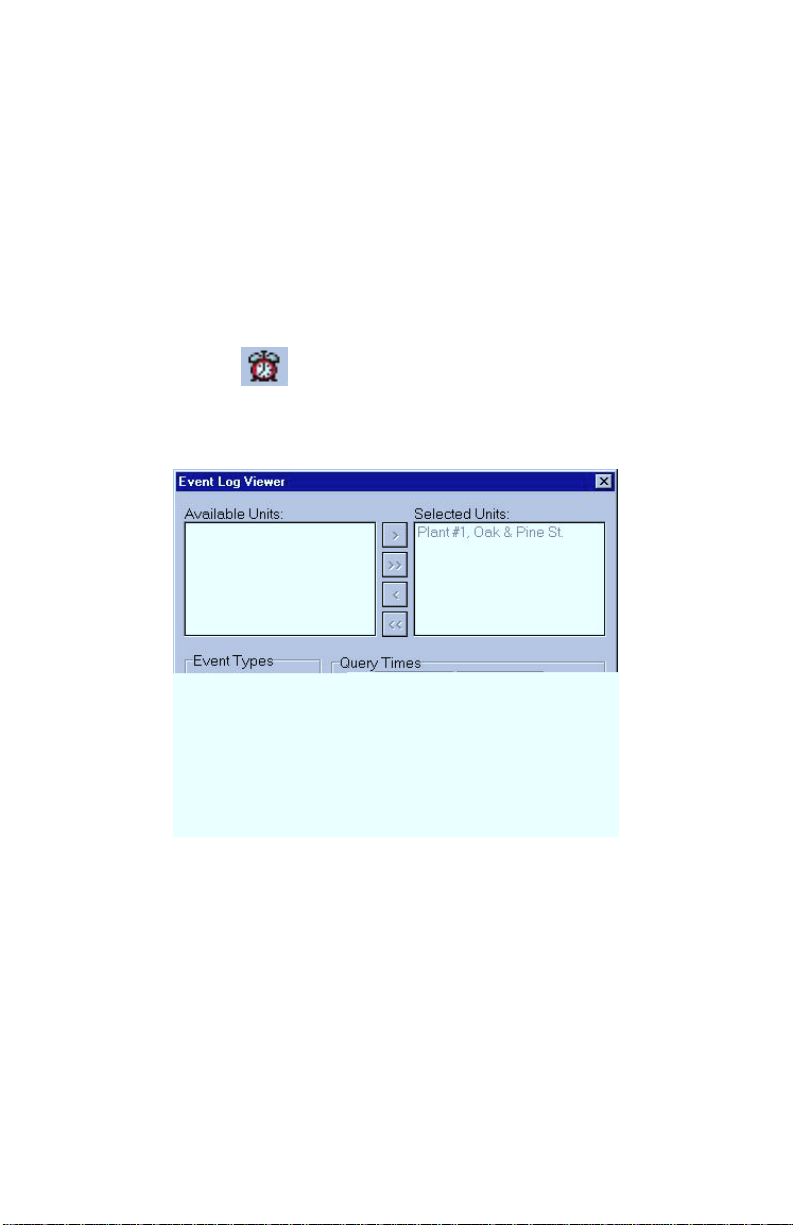
outgoing phone calls, and alarm acknowledgments. See Appendix A
for a complete list of events stored by the Event Logger. Once the
Event Log is full, the oldest record is overwritten by the newest.
Downloading the Event Logger:
To view CPP Monitor 2000’s Event Log, the unit’s Event Logger
must first be downloaded to your PC. You must be on-line with the
unit to download the Event Log. Once you are on-line, choose
“Functions” from the main menu, then select “View Events.” You
can also access the Event Logger from the Toolbar button labeled
Events.
The following event log form will appear:
Chapter 4: Programming
To download the Event Logger, click “Download Events.”
Every time a unit’s Event Logger is downloaded, the Manager 2000
software adds the new information to that unit’s database in your
PC. It also checks for and filters out duplicate Event Log records.
The downloaded Event Logger can then be viewed off-line.
Viewing the Event Logger:
Once the Event Logger has been downloaded, it can be viewed on
the form called “Event Viewer.”
67
Page 68
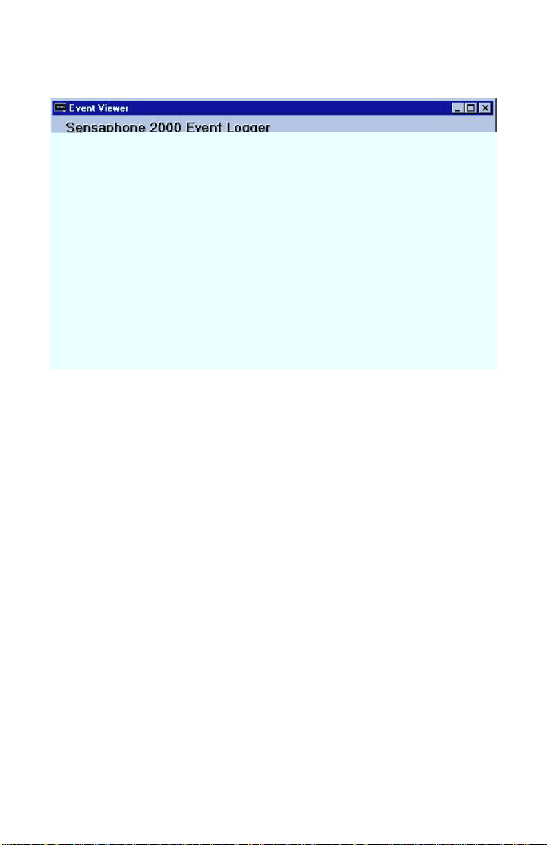
CPP Monitor 2000 User’s Manual
Below is a list of programming parameters for viewing the Event
Logger:
event viewer form
Unit selection:
68
Since the MANAGER 2000 software can contain Event Log
information for multiple CPP Monitor 2000 units, you must choose
which unit’s Event Log you wish to display. Look at the Event Log
Viewer form. In the window labeled “Available Units” is a list of all
CPP Monitor 2000 units currently recognized by your PC. Highlight
a unit by clicking on the unit name, and use the four add/remove
buttons (>,>>,<,<<) to select the desired unit(s) as follows:
‘add’ ([>]) - Adds the unit to the “Selected Units” list.
‘add all’ ([>>]) - Adds all units to the “Selected Units” list.
‘remove’ ([<]) - Removes the unit from the “Selected Units” list.
‘remove all’ ([<<]) - Removes all units from the “Selected Units”
list.
Page 69
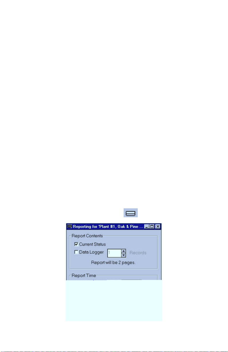
Event types:
Select here the types of events to display: All Events or Alarms
Only.
Query Times:
Selects a range of event times to display. “Inc.All” will include all
event times in the CPP Monitor 2000, with a “To” date stretching
into the future. “To Now” resets the “To” time to the exact moment
you click on the button.
View:
Displays the selected Event Log records.
Reset Event Logger:
Deletes all Event Log records from your PC’s database.
REPORTS
CPP Monitor 2000 can send periodic reports to selected Fax or Email destinations. Reports may include either the current status of
all inputs, stored Data Logger information, or both. You must be online with the unit to program Report parameters. Once you are online, choose “Programming” from the main menu, then select
“Reports.” You can also access the Reports programming from the
Toolbar button labeled Reports.
Chapter 4: Programming
reports form
69
Page 70

CPP Monitor 2000 User’s Manual
Below is a list of Report programming parameters, their default
settings and the range of programming for each parameter.
Current Status:
To send the current status of all inputs with the report, check this
box.
Data Logger:
To send information stored in CPP Monitor 2000’s Data Logger,
check this box. If this box is checked, you must select the number
of Data Log records to send with the report. CPP Monitor 2000 will
send the number of records requested beginning with the most
recent record and follow in order of newest to oldest. (Note: A data
Log record is a time slice of whatever inputs were being logged.)
When CPP Monitor 2000 sends Data Logger information with a
report, it DOES NOT erase the information from the unit.
Use Start Time:
CPP Monitor 2000 can be programmed to begin sending reports at a
particular time of day. When CPP Monitor 2000’s internal clock
reaches the programmed Start Time, the unit will begin sending
reports to the selected destinations. The Start Time function is used
to delay the start of reporting. Once reporting has begun, the Start
Time programming is ignored.
Default Setting: 12:00:00AM
Report Interval:
Time between reports.
70
Note: To disable the Start Time function, leave the
Start Time at the default setting of 12:00:00AM.
CPP Monitor 2000 will begin sending reports after the
first Report Interval has expired.
Programmable range: Minimum - 0 hours, 1 minutes
Maximum - 24 hours, 0 minutes
Default Setting: 24 hours, 0 minutes
Page 71

POLLING
Chapter 4: Programming
Polling occurs when a PC automatically calls a remote CPP Monitor
2000 with a modem at a predetermined time and retrieves information. The concept is similar to setting an alarm clock to download a
unit’s Data Logger or Event Log.
Polling is a useful feature for users who need to save more data than
the CPP Monitor 2000 is capable of holding. The unit’s Data Logger
can hold 32,768 input readings. This means that if one input is
being logged, CPP Monitor 2000 can store up to 32,768 data
samples, but if 10 inputs are being logged, the unit can only store up
to 3,276 data samples. Once the CPP Monitor 2000 has filled its
Data Logger, it will begin overwriting the oldest Data Log samples
with new samples. If it is important that you save all of your data
samples, and you intend to log more data than the CPP Monitor 2000
can hold, YOU MUST DOWNLOAD YOUR DATA.
To manually download CPP Monitor 2000 Data Log information to
your PC, simply press “Retrieve Data” on the “Datalogging”
programming form while on-line with the unit. The contents of the
Data Logger will be transferred to a database in your PC.
The process is the same for downloading the Event Log. While online with the unit, press “Download Events” on the “Event Log
Viewer” form and the unit’s Event Log is saved to your PC. Polling
is nothing more than choosing a time for these features to automatically execute.
To set up Polling, open the unit On-line or Off-line. To program
Polling, choose “Polling,” then “Unit Schedule” from the main
menu, or click on the Toolbar button labeled Unit Schedule.
71
Page 72

CPP Monitor 2000 User’s Manual
polling setup form
The screen displayed is the Polling Setup screen for the currently
selected unit. This screen allows you to choose what type of poll
you would like to schedule and when the poll will take place.
Each time your PC polls a CPP Monitor 2000, you may download the
contents of the selected unit’s Data Logger, Event Logger, or both.
In the top left corner of the “Polling Setup” form there are 3 buttons
labeled Data Log, Event Log, and Both.
To schedule a poll, click on one of the buttons, drag it to the desired
day of the week column, and drop it at the desired hour. The Polling
Setup form is a WYSIWYG (What You See Is What You Get)
calendar interface. Once you have released the button, you have
scheduled a poll. If you wish to change the time of a poll, drag it to
its new time and drop it. If you want to remove a poll, drag the poll
over the trash can icon and drop it. The poll will disappear and is
no longer scheduled.
Global View:
This button brings up a form that looks very similar to the Polling
Setup form, except it contains all of the scheduled polls for every
72
Page 73
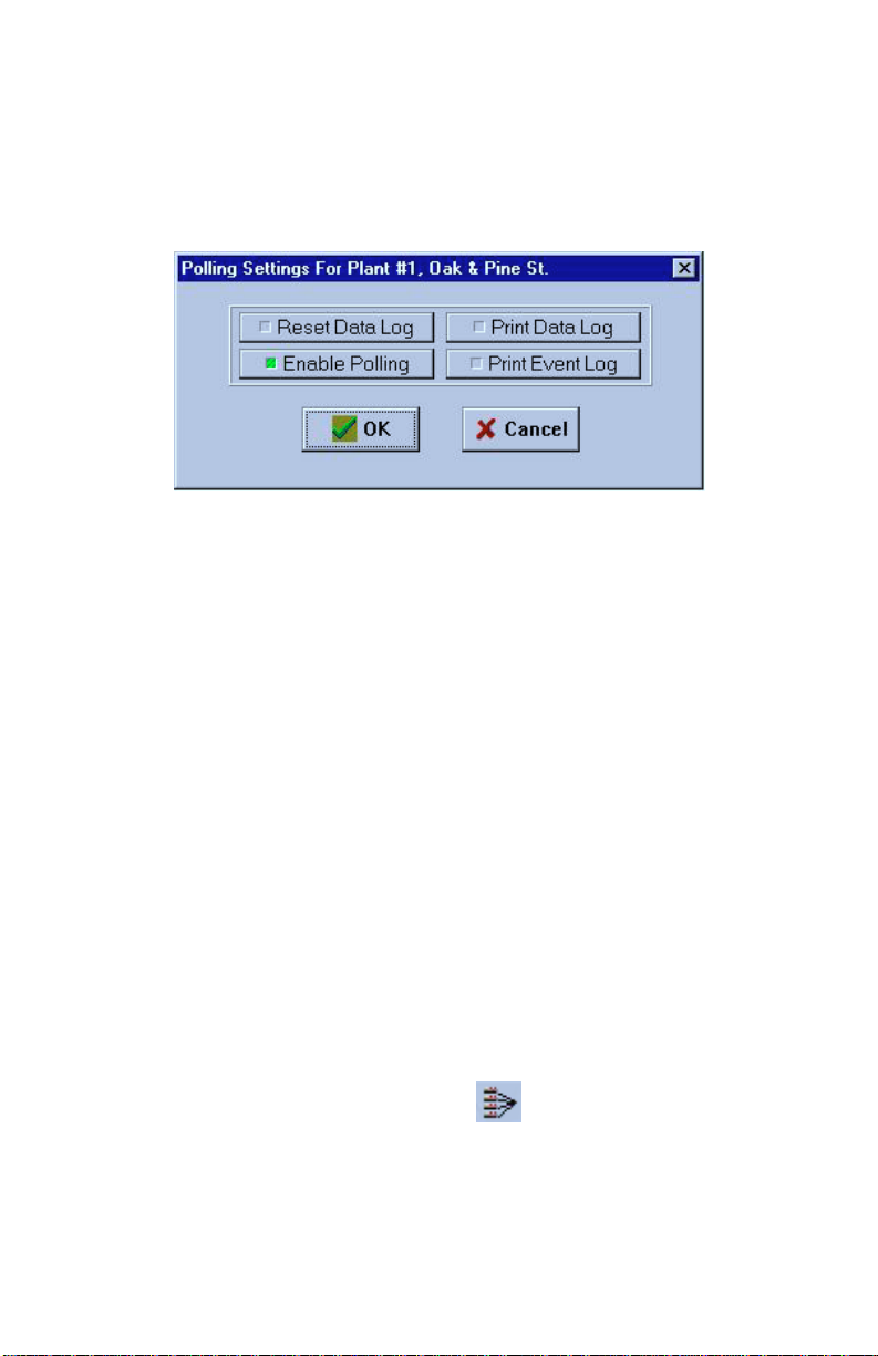
unit. If you wish to see the scheduled polls for a given unit you can
select that unit in the combo box on the Polling Summary form.
Settings:
Click this button to set the following Polling options:
Reset Data Log:
If this button is lit, the CPP Monitor 2000’s Data Logger will be reset
(cleared) once the poll is complete.
Chapter 4: Programming
Note: The CPP Monitor 2000 unit will not automatically delete its Data Log records when they are
downloaded, unless you select this button. Resetting
the Data Logger after polling is useful if you also
intend to print the Data Log records after polling. If
you do not clear the Data Log after a poll, the next
time you poll the unit you will download and print
the same records again.
Enable Polling:
If this button is lit, the current unit will be among the units polled at
the start of every hour. In order for your PC to make the scheduled
Polling phone calls to units, you must enable Polling for each unit
and turn on the master polling control. The master polling control
is enabled by selecting Enable from the Polling menu or by clicking
Polling Mode from the Toolbar.
Note: If you are logged into a unit with the PC,
polling for that hour will not occur until you exit the
unit. Also, it is important to note that if for some
reason you are logged into a unit for an entire hour,
your PC will not make the phone calls for that hour.
73
Page 74

CPP Monitor 2000 User’s Manual
If you are going to utilize the polling feature heavily,
try to schedule polling at times when it is unlikely
that your PC is being used.
Print Data Log button
If this button is lit, the PC will print the downloaded Data Logger
information after each poll.
Print Event Log button
If this button is lit, the PC will print the downloaded Event Logger
information after each poll.
Note: The data downloaded from the CPP Monitor
2000 may be quite large, and printing all of it may
take some time. Remember to keep an adequate
supply of paper in your printer and also make sure
that your printer has enough memory to handle large
jobs. Automatic printing at the time of the poll
allows you to schedule the print job at a time when
it’s less likely to interfere with other activities.
74
Page 75

Chapter 5: Status Report/Voice
Chapter 5: Status Report and Voice Messages
The CPP Monitor 2000 provides a voice status report via telephone
using its own internal voice in combination with your recorded
input messages. This allows you to set up a custom system that
fully describes the unit’s location, the input having a problem, its
current value and units of measure. The messages may be recorded
either at the unit by plugging a telephone into the Voice Record
jack, or remotely by calling the unit. This section will describe how
to program identification and input messages along with some
examples. In addition, obtaining a status report both locally and
remotely will be discussed.
Playing/Recording Messages using the Voice Record Jack
To play and record messages using the Voice Record jack you will
need a simple single-line Touch-Tone telephone. Plug this telephone directly into the 2000’s Voice Record jack. (DO NOT connect
the Voice Record jack to a telephone line or to a digital telephone
system. This will permanently damage the unit). When you plug the
telephone into the jack and lift the handset, the unit will recite a
status report. At the end of the status report, the unit will say “Enter
Password.” This is the voice password. Enter the voice password
using the telephone keypad buttons. If the voice password is
entered correctly, CPP Monitor 2000 will say “OK.” If not, the unit
will beep then say “ERROR,” and you will have to hang up the
phone and try again.
Once the voice password is accepted, Touch-Tone commands are
used to record and play back messages as well as listen to a status
report. The commands are listed below:
Play Command Record Command Erase Command Message Description
* 1 # 1 ##1 Input Message #1
* 2 # 2 ##2 Input Message #2
* 3 # 3 ##3 Input Message #3
* 4 # 4 ##4 Input Message #4
* 5 # 5 ##5 Input Message #5
* 6 # 6 ##6 Input Message #6
* 7 # 7 ##7 Input Message #7
* 8 # 8 ##8 Input Message #8
* 9 # 9 ##9 Identification (ID) Message
* * Status Report
75
Page 76

CPP Monitor 2000 User’s Manual
To record a message, press the [#] key followed by the message
number you want. For example, to record the ID message, press [#]
then 9. After you hear the start beep, begin speaking into the phone.
You have until the second beep to complete your message. You have
6 seconds of recording time for the ID message and 4 seconds for
each of the 8 input messages.
To play back a message, press the [*] key followed by the message
number you want. For example, to play the ID message, press [*]
then 9.
To request a complete status report, press the [*] key twice.
Note: Since the unit can only communicate with one
device at a time, it will not answer any calls nor make
any calls while you are on-line in local voice mode.
Local Status Report
To receive a voice status report at the unit, plug a telephone into the
Voice Record jack. After a few seconds the unit will begin reciting
a status report. At the end of the report it will ask for a password.
The password is the Voice Password required to change voice
messages and acknowledge alarms. If entered correctly, the unit
will allow you to use the Touch-Tone commands to record/listen to
messages and acknowledge alarms. When finished simply hang up.
Status Report
76
To receive a voice status report remotely, call the unit and after you
hear the unit beep, press any Touch Tone within 3 seconds. The unit
will then recite a status report. If the unit starts its modem tone
sequence, simply wait until it finishes. A status report will begin as
soon the tones finish. At the end of the report it will ask for a
password. The password is the Voice Password required to change
voice messages and acknowledge alarms. If entered correctly, the
unit will allow you to use the Touch-Tone commands to record/
listen to messages and acknowledge alarms. When finished simply
hang up. The unit will disconnect itself automatically if no TouchTone commands are received within 10 seconds.
Page 77

Sample Status Report
Hello, this is (Unit Phone Number)
Input one (recorded message #1), (input value), (units), (alarm status)
Input two (recorded message #2), (input value), (units), (alarm status)
Input three (recorded message #3), (input value), (units), (alarm status)
Input four (recorded message #4), (input value), (units), (alarm status)
Input five (recorded message #5), (input value), (units), (alarm status)
Input six (recorded message #6), (input value), (units), (alarm status)
Input seven (recorded message #7), (input value), (units), (alarm status)
Input eight (recorded message #8), (input value), (units), (alarm status)
The electricity is On/Off
Battery condition 8.7 volts, OK/Low/Very Low
Chapter 5: Status Report/Voice
77
Page 78

CPP Monitor 2000 User’s Manual
78
Page 79

Chapter 6: Operation
Chapter 6: Operation
After installation and programming have been completed,
CPP Monitor 2000 is fully operational. This chapter explains how
CPP Monitor 2000 operates.
PART ONE: ALARM DIALOUT AND ACKNOWLEDGMENT
There are 3 stages to a complete alarm event: 1) Alarm Recognition,
2) Alarm Notification, 3) Acknowledgment. Note that not all alert
conditions will go through each stage. For example, some may not
meet the recognition time.
Alarm Recognition:
1) CPP Monitor 2000 monitors 8 inputs plus power failure. When the
status of an input changes or exceeds user-programmed limits, it
causes an alert condition.
2) If the alert condition lasts long enough to meet its programmed
recognition time, the alert condition becomes an alarm and
CPP Monitor 2000 begins the alarm notification sequence.
Alarm Notification:
CPP Monitor 2000 can make 6 types of phone calls: Voice, Fax, Email, Modem, Beeper, and Alphanumeric pager.
Dialout Note: Call Progress
CPP Monitor 2000 monitors call progress when dialing out. If
CPP Monitor 2000 dials out and encounters a busy signal or no
answer within 30 seconds, the unit hangs up, waits the programmed
intercall delay time, and then dials the next phone number.
79
Page 80

CPP Monitor 2000 User’s Manual
Alarm Call Mode: Until Acknowledged vs. Inform
Until Acknowledged:
Destinations programmed with Alarm Call Mode “Until Acknowl-
edged” will continue to be contacted until one of them acknowledges the alarm.
Note: Fax and E-mail destinations cannot be programmed as “Until
Acknowledged.”
Inform:
Destinations programmed with Alarm Call Mode “Inform” will be
contacted until the alarm message has been successfully delivered
one time. If a transmission to Alarm Call Mode “Inform” destination was successful, that destination will not be contacted again.
Important: Destinations programmed as Alarm Call
Mode “Inform” CANNOT ACKNOWLEDGE
ALARMS.
Alarm Dialout - Voice
When dialing out to a destination programmed as “voice,” CPP
Monitor 2000 waits for the phone to be answered, then recites its userrecorded identification message, then the message identifying the
input that has gone into alarm.
Below is an example of what CPP Monitor 2000 might say during a
typical ‘voice’ dialout:
“Hello, this is (user recorded ID message)”
“The electricity is off”
“Hello, this is (user recorded ID message)”
“The electricity is off”
“Hello, this is (user recorded ID message)”
80
Page 81

“The electricity is off”
“Enter acknowledgment code.”
In this example, the number of Voice Message Repetitions was set
to three.
Note: If the call reaches an answering machine, the
message will be recorded, but CPP Monitor 2000 will
be talking over your outgoing message, so you will
probably lose part of the first alarm message repetition.
Alarm Dialout - Beeper
When dialing out to a destination programmed as “Beeper,”
CPP Monitor 2000 leaves a number (usually the unit’s own phone
number) on the display of a numeric beeper.
IMPORTANT: When dialing out to a phone number
programmed as “Beeper,” CPP Monitor 2000 DOES
NOT speak a voice message. It calls the beeper
company or service, enters the number to be displayed on the beeper, then hangs up.
Chapter 6: Operation
Alarm Dialout - Alphanumeric Pager
When dialing out to a destination programmed as “Alpha,” CPP
Monitor 2000 leaves a text message up to 80 characters long on the
display of an alphanumeric pager.
IMPORTANT: When dialing out to a phone number
programmed as “Alpha,” CPP Monitor 2000 DOES
NOT speak a voice message. It calls the pager
company or service, transmits the information to be
displayed on the pager, then hangs up.
Alarm Dialout - Modem
When dialing out to a destination programmed as “Modem,”
CPP Monitor 2000 waits for the phone to be answered by a modem,
establishes a data connection, then transmits its alarm message.
IMPORTANT: When dialing out to a phone number
programmed as “Modem,” CPP Monitor 2000 DOES
81
Page 82

CPP Monitor 2000 User’s Manual
NOT speak a voice message. It is expecting the call
to be answered by a PC running CPP Manager
2000 Windows software. Once a connection is
established, the CPP Monitor 2000 transmits the alarm
information, then hangs up.
Alarm Dialout - Fax
When dialing out to a destination programmed as “Fax” CPP Monitor
2000 waits for the phone to be answered by a fax machine, establishes a connection, then faxes its alarm message.
IMPORTANT: When dialing out to a phone number
programmed as “Fax,” CPP Monitor 2000 DOES NOT
speak a voice message. It is expecting the call to be
answered by a fax machine. Once a connection is
established, the CPP Monitor 2000 faxes the alarm
information, then hangs up.
Alarm Dialout - E-mail
When dialing out to a destination programmed as “E-mail,”
CPP Monitor 2000 is pre-programmed to call the toll-free 800
number of the Phonetics’ E-mail server system. Once connected, the
unit delivers its alarm message to the E-mail address programmed
in the destination field.
IMPORTANT: When dialing out to a phone number
programmed as E-mail, CPP Monitor 2000 DOES
NOT speak a voice message. It is expecting the call
to be answered by the Phonetics’ E-mail server
system. Once a connection is established, the CPP
Monitor 2000 E-mails the alarm message, then hangs
up.
ALARM ACKNOWLEDGMENT:
Alarm Acknowledgment - Voice Dialout
Repeated below is the same example of what CPP Monitor 2000
might say during a typical “voice” dialout:
“Hello, this is (user recorded ID message)”
“The electricity is off”
82
Page 83

Chapter 6: Operation
“Hello, this is (user recorded ID message)”
“The electricity is off”
“Hello, this is (user recorded ID message)”
“The electricity is off”
“Enter acknowledgment code.”
CPP Monitor 2000 will now wait 5 seconds for the Touch-Tone
acknowledgment code to be entered. After the last digit of the
acknowledgment code has been received, CPP Monitor 2000 will
respond by saying: “Alarm Acknowledged.” The alarm has been
acknowledged and the unit will hang up. Once the alarm has been
acknowledged, the dialout process stops.
If the Touch-Tone acknowledgment code is not received, CPP
Monitor 2000 will respond by saying: “beep,” “error,” “goodbye.” The
alarm has not been acknowledged. CPP Monitor 2000 will hang up
and wait for a callback acknowledgment. This waiting period is
called the “intercall delay time.” During this time you may call the
unit back from a Touch-Tone phone. Wait for the unit to beep.
Then hit any key on the phone, and the unit will give a voice report.
Once you receive the complete report, enter the code to acknowledge the alarm. NOTE: An alarm cannot be acknowledged using a
pulse (rotary) telephone.
Alarm Acknowledgment - Beeper Dialout
CPP Monitor 2000 will dial out to your beeper service and leave a
number on the display of your beeper. (See Programming Section)
The unit will then hang up without speaking a voice message and
wait for callback acknowledgment. This waiting period is called the
“intercall delay time.” During this time you may call the unit back
from a Touch-Tone phone to receive a report of the alarm condition
and acknowledge the alarm by entering the acknowledgment code.
NOTE: An alarm cannot be acknowledged using a
pulse (rotary) telephone.
83
Page 84

CPP Monitor 2000 User’s Manual
Below is an example of what CPP Monitor 2000 will say when you
call it back to acknowledge a typical alarm:
“Hello, this is (user recorded ID message)”
“The electricity is off”
“Hello, this is (user recorded ID message)”
“The electricity is off”
“Hello, this is (user recorded ID message)”
“The electricity is off”
“Enter acknowledgment code.”
CPP Monitor 2000 will now wait 5 seconds for the Touch-Tone
acknowledgment code to be entered. After the last digit of the
acknowledgment code has been received, CPP Monitor 2000 will
respond by saying: “Alarm Acknowledged.” The alarm has been
acknowledged and the unit will hang up. Once the alarm has been
acknowledged, the dialout process stops.
If the Touch-Tone acknowledgment code is not received, CPP
Monitor 2000 will respond by saying: “beep,” “error,” “goodbye.” The
alarm has not been acknowledged. CPP Monitor 2000 will hang up
and wait for a callback acknowledgment. This waiting period is
called the “intercall delay time.” During this time you may call the
unit back from a Touch-Tone phone. Wait for the unit to beep.
Then hit any key on the phone, and the unit will give a voice report.
Once you receive the complete report, enter the code to acknowledge the alarm. NOTE: An alarm cannot be acknowledged using a
pulse (rotary) telephone.
TIP: When CPP Monitor 2000 is programmed to make
calls to beepers, make sure the intercall delay time is
long enough to give the person carrying the beeper
some time to get to a phone to call the unit back.
84
Page 85

Chapter 6: Operation
Alarm Acknowledgment - Alphanumeric Pager Dialout
CPP Monitor 2000 will dial out to your alphanumeric pager service
and leave a message on the display of your pager. (See Programming Section, Chapter Four, for dialing to beepers/pagers). The unit
will then hang up without speaking a voice message and wait for
callback acknowledgment. This waiting period is called the
“intercall delay time.” During this time you may call the unit back
from a Touch-Tone phone to receive a report of the alarm condition
and acknowledge the alarm by entering the acknowledgment code.
NOTE: An alarm cannot be acknowledged using a
pulse (rotary) telephone.
Below is an example of what CPP Monitor 2000 will say when you
call it back to acknowledge a typical alarm:
“Hello, this is (ID message)”
Input 1, closed, alarm exists
“Hello, this is (ID message)”
Input 1, closed, alarm exists
“Hello, this is (ID message)”
Input 1, closed, alarm exists
“Enter acknowledgment code.”
CPP Monitor 2000 will now wait 5 seconds for the Touch-Tone
acknowledgment code to be entered. After the last digit of the
acknowledgment code has been received, CPP Monitor 2000 will
respond by saying, “Alarm Acknowledged.” The alarm has been
acknowledged and the unit will hang up. Once the alarm has been
acknowledged, the dialout process stops.
If the Touch-Tone acknowledgment code is not received, CPP
Monitor 2000 will respond by saying: “beep,” “error,” “goodbye.” The
alarm has not been acknowledged. CPP Monitor 2000 will hang up
85
Page 86

CPP Monitor 2000 User’s Manual
and wait for a callback acknowledgment. This waiting period is
called the “intercall delay time.” During this time you may call the
unit back from a Touch-Tone phone. Wait for the unit to beep.
Then hit any key on the phone, and the unit will give a voice report.
Once you receive the complete report, enter the code to acknowledge the alarm. NOTE: An alarm cannot be acknowledged using a
pulse (rotary) telephone.
TIP: When CPP Monitor 2000 is programmed to make
calls to alphanumeric pagers, make sure the intercall
delay time is long enough to give the person carrying
the pager some time to get to a phone to call the unit
back.
Alarm Acknowledgment - Modem Dialout
CPP Monitor 2000 will dial to a waiting PC running Phonetics
Manager 2000 software and deliver an alarm message that will be
logged by the software. The software may be programmed to
acknowledge the alarm.
If the S2000 software acknowledges the alarm, the unit will transmit
the alarm information to the PC, hang up, and the dialout process
stops. If not, CPP Monitor 2000 will transmit the alarm information
to the PC, hang up and wait for a callback acknowledgment. This
waiting period is called the “intercall delay time.” During this time
you may call the unit back from a Touch-Tone phone and enter the
code to acknowledge the alarm. NOTE: An alarm cannot be
acknowledged using a pulse (rotary) telephone.
Alarm Acknowledgment - Automatic (Max Calls)
CPP Monitor 2000 has the ability to acknowledge itself by using the
Max Calls function. The unit keeps a count of the number of phone
calls it makes for a particular alarm. Once the number of calls made
reaches Max Calls, CPP Monitor 2000 will acknowledge the alarm
and stop the dialout process.
PART TWO: REPORT DIALOUT
The unit is capable of sending automatic reports on a programmable
time basis, (i.e. Send a report every x hours starting at time xx:xx).
Reports may be sent via fax or e-mail only, and will be sent to all
destinations programmed to receive reports. Reports cover the unit
86
Page 87

data, which includes the current conditions of each input, power
status, and battery condition. If the Data Logger is enabled and
programmed to send with reports, a Data Log report will also be
sent at this time.
PART THREE: CALL-IN STATUS
Using PC with Manager 2000 Windows Software: At any time the
unit is idle (not dialing out or communicating locally), you can call
into it using a modem. CPP Monitor 2000 will answer after its
programmed “Rings To Answer,” connect, and go on-line. At this
point you have entered an on-line session identical to the local
programming session, and may program the unit as necessary.
Voice Mode:
You can also call into the CPP Monitor 2000 using a Touch-Tone
telephone. After answering, CPP Monitor 2000 will beep once.
Immediately press any key on your Touch-Tone keypad to get a
voice status report. If the CPP Monitor 2000 doesn’t receive a
Touch-Tone signal within a few seconds, it will attempt to make a
data (modem) connection. If a data connection isn’t made after the
programmed “Carrier Wait Time,” CPP Monitor 2000 will again
switch to voice mode and recite a status report. Immediately
following the status report, CPP Monitor 2000 prompts you for a
voice-mode password. This password allows you to use Touch-Tone
commands to both listen to and record the unit’s voice messages.
Chapter 6: Operation
To listen to a recorded alarm message:
1. Press the [*] key on your phone.
2. Press the corresponding input number key: 1-8, or press 9 to
listen to the ID message.
CPP Monitor 2000 will recite the corresponding message.
To record a message remotely:
1. Press the # key on your phone.
2. For an input alarm message, press the corresponding input
number key: 1-8, or press 9 to record the ID message.
87
Page 88

CPP Monitor 2000 User’s Manual
After the beep, say your message clearly. The input alarm messages
may be up to 4 seconds long. The ID message can be up to 6
seconds long. CPP Monitor 2000 will beep at the end of the allotted
time.
Below is an example of a voice status report:
“Hello, this is 610-555-2000” (ID number)
“This is the CPP Monitor 2000 in lift station 21.” (user-recorded ID
message)
“Input 1, jockey pump #1 overload, closed, OK”
“Input 2, jockey pump #2 overload, closed, OK”
“Input 3, main pump overload, closed, OK”
“Input 4, wet well level, 8.9 feet, OK”
“Input 5, dry well sump pump, Off, OK”
“Input 6, exit flow, 746.9 gpm, OK”
“Input 7, wet well air temperature, 54.4 degrees fahrenheit, OK”
“Input 8, waste grinder motor overload, closed, OK”
“The electricity is On”
“Battery voltage 8.6 volts, OK.”
“Goodbye”
88
Page 89

Chapter 7: Auto-Answer and Polling
Chapter 7: Polling Mode & Auto Answer Mode
Polling mode and Auto Answer mode allow your PC to communicate automatically with multiple CPP Monitor 2000s. Polling is the
process of calling units to retrieve the Data Log or Event Log (see
“Datalogging,” “Event Logger,” and “Polling” sections in Chapter
Four). Auto Answer mode let’s your PC receive alarm calls when
the destination type is set to modem. In order to receive alarm calls
or have the software perform polling you must have the program
running and have one or both modes enabled. When the software
receives an alarm message it will display it on your screen immediately as well as update the Event Log for that particular unit. When
using these features, your computer and modem must remain ON
continuously.
Enabling Auto Answer Mode
You can enable Auto Answer mode by selecting Functions>Auto
Answer from the menu bar or by clicking on the Answer Mode icon
in the Toolbar.
Note that Auto Answer mode can only be enabled if you are not
connected with a unit. Once you’re connected, it becomes grayed
out.
Enabling Polling Mode
To enable Polling mode, click on the Polling Mode icon on the
Toolbar or select Polling>Enable from the menu bar. This is the
global polling-enable control. In addition, each unit must have
Polling enabled (see Chapter Four for specific Polling Settings).
89
Page 90

CPP Monitor 2000 User’s Manual
PB
Page 91

APPENDIX A
System Events List
EVENT LOGGER - List of System Events
Startup completed
Unit reset by user
Data Logger reset
Data Logger started
Data Logger stopped
Data Logger downloaded
Data Logger full
Diagnostic - hardware reset
Diagnostic - reset program RAM
Appendix A: System Events
Diagnostic - reset all RAM
Password attempt successful for status only
Password attempt successful for programming access
Password attempt failed
Alarm detected
Alarm reset time expired - alarm detected
Alarm detected but not configured
Alarm acknowledged by max calls
Alarm acknowledged by 15 calls to phone 1
Alarm acknowledged by inbound phone call
Acknowledgment request received
No acknowledgment received on outbound call
Dialing “Until Acknowledged” phone number
Dialing “Inform” phone number
Phone busy
91
Page 92

CPP Monitor 2000 User’s Manual
No answer
Voice call answered
Modem connect
Fax connect
E-mail connect
Numeric pager connect
Alpha pager connect
Message delivered
Hanging up
Inbound phone call received
Giving voice report (for inbound calls)
Inbound phone call terminated
PB
Page 93

APPENDIX B
Engineering Specifications
Electrical
Power Requirements:
120VAC 60Hz 10W (UL listed power supply)
Power Surge Protection:
17V Metal Oxide Varistor and solid state transient protection
Battery System:
(6) C-cell Rechargeable Nicad batteries (not included)
Battery Charging:
Precision voltage controlled charging system
Battery Backup time:
10 - 15 hrs
Appendix B:Engineering Specfifications
Inputs
Input Channels:
8 universal, AC Power and battery
Input Types:
Normally Open/Normally Closed contact, 2.8K/10K thermistor, 4-20mA
current loop, 0-5V analog voltage
Input Conditioning:
Open Contacts see 5VDC, closed contacts see 0.5mA, Thermistors, see
5VDC through 10K Ohms, 4-20mA inputs, see 220 Ohms to
ground, 0-5V analog inputs see 5M Ohms
Input Fault Protection:
35V over/under voltage protection
Input Resolution:
10 bits
93
Page 94

CPP Monitor 2000 User’s Manual
Datalogging
Number of Channels:
Inputs 1-8, AC Power & Nicad Battery backup (selectable)
Total Number of Samples: 32,768
Sampling Rate:
Programmable from 1 second to 200 hours
All samples include date and time.
Communication
Phone Line Connection:
RJ11 jack for connection to the public switched telephone network; pulse
& tone dialing
Communication Types:
Voice, Fax, E-mail, modem, alphanumeric pager, numeric pager
Dialing Parameters:
Calls up to 32 destinations (telephone numbers or E-mail addresses)
32 digit telephone numbers & 64 character E-mail addresses
Time between calls programmable from 10 seconds to 60 minutes
Maximum number of calling rounds programmable from 1 to 100
Programmable call list per input
Alarm acknowledgment via touch tones or callback
Call progress monitoring to detect dial tone, busy signals & ringback
PB
Modem:
Data throughput 14,400 bps, 14,400 bps Fax
Protocols: V.32bis, V.32, V.22bis, V.22A/B, V.23, V.21, Bell 212A &103
Speech Technology:
(8) User-recorded voice alarm messages (4 seconds each) and (1)
Identification message (5 seconds); 53 seconds of pre-recorded
speech; 2.7KHz bandwidth, selectable speech for units of measure
Phone Line Surge Protection:
275V Metal Oxide Varistor
Page 95

Programming
Programming Connection:
RS232 DB25 Female DCE; 38,400 baud
Programming Method:
local or remote PC with CPP Monitor 2000 Software for Microsoft
Data Retention:
2 years typical (lithium battery backed static RAM)
Visual Indicators
Input Alarm Status:
1 red LED for each channel
AC Power Alarm:
1 red LED
System On:
1 green LED
Battery Condition:
1 green LED
Appendix B:Engineering Specfifications
Windows (included)
Phone Line Off-hook:
1 amber LED
Environmental
Operating Temperature Range:
32°-122° F (0°-50° C)
Humidity:
0-90% RH, non-condensing
Physical
Enclosure:
Durable aluminum enclosure with integral mounting brackets for wall-
mounting or panel mounting
95
Page 96

CPP Monitor 2000 User’s Manual
Dimensions:
12.1"W x 7.2"H x 1.6"D
Weight:
3 lbs. (4 lbs. with batteries)
Approvals
FCC Part 68
FCC Part 15 Class A
Warranty
One year parts and labor warranty.
Specifications subject to change without notice.
E-mail delivery requires additional service fees.
Copyright 1996 Phonetics, Inc. Sensaphone is a
registered trademark of Phonetics, Inc.
PB
Crucial Power Products
5900 Triumph St.
Commerce, CA 90040
Phone: (800)244-4069Fax: (800) 244-2346
Page 97

APPENDIX C
Thermistor Tables
2.8K Thermistor Data
Degrees Celsius Resistance (Ohms)
-50 187,625
-40 94,206
-30 49,549
-20 27,180
-10 15,491
0 9,142
10 5,572
Appendix C: Thermistor Tables
20 3,498
30 2,256
40 1,491
50 1,009
60 697
70 490
80 351
97
Page 98

CPP Monitor 2000 User’s Manual
10K Thermistor Data
Degrees Celsius Resistance (Ohms)
-50 441.3K
-40 239.8K
-30 135.2K
-20 78.91K
-10 47.54
0 29.49K
10 18.79K
20 12.25K
30 8,194
PB
40 5,592
50 3,893
60 2,760
70 1,990
80 1,458
90 1,084
100 816.8
110 623.5
120 481.8
130 376.4
140 297.2
150 237.0
Page 99

APPENDIX D
RS232 Specifications
DB25 Socket Configuration:DCE Female
Start/Stop Protocol: None
Port Speed: 38,400 bps
Communications Protocol: 8 data bits, no parity, 1 stop bit
RS232 Pin Assignment:
Pin Signal Symbol Direction
1 Frame Ground FG N/A
2 Transmitted Data TD to Sensaphone
3 Received Data RD from Sensaphone
7 Signal Ground SG N/A
Appendix D: RS232 Specifications
99
Page 100

CPP Monitor 2000 User’s Manual
PB
 Loading...