

Phoenix Contact TC ROUTER 3002T-4G, TC ROUTER 2002T-4G, TC ROUTER 3002T-3G, TC ROUTER 3002T-4G ATT, TC ROUTER 2002T-3G User Manual
...
Industrial mobile router with integrated
firewall and VPN
User manual
UM EN TC ROUTER ... 3G/4G

User manual
Industrial mobile router with integrated firewall and VPN
UM EN TC ROUTER ... 3G/4G, Revision 01
This user manual is valid for:
Designation Software release Order No.
TC ROUTER 3002T-4G 2.04.11 2702528
TC ROUTER 3002T-3G 2.04.11 2702529
TC ROUTER 2002T-4G 2.04.11 2702530
TC ROUTER 2002T-3G 2.04.11 2702531
TC ROUTER 3002T-4G VZW 2.04.11 2702532
TC ROUTER 3002T-4G ATT 2.04.11 2702533
2018-09-07
107025_en_01
PHOENIX CONTACT GmbH & Co. KG • Flachsmarktstraße 8 • 32825 Blomberg • Germany
phoenixcontact.com

Table of contents
Table of contents
1 For your safety ...........................................................................................................................5
1.1 Identification of warning notes ............................................................................... 5
1.2 Qualification of users .............................................................................................5
1.3 Field of application of the product.......................................................................... 6
1.4 Safety notes .......................................................................................................... 6
1.5 UL warning notes (only TC ROUTER 3002T-4G VZW and
TC ROUTER 3002T-4G ATT)................................................................................7
2 Installation ..................................................................................................................................9
2.1 Product description................................................................................................ 9
2.2 Structure.............................................................................................................. 10
2.3 Mounting and removal......................................................................................... 12
2.4 Inserting the SIM card.......................................................................................... 13
2.5 Connection .......................................................................................................... 14
2.6 Resetting the router ............................................................................................. 17
3 Configuration via web-based management ..............................................................................19
3.1 Connection requirements .................................................................................... 19
3.2 Starting web-based management (WBM) ........................................................... 19
3.3 Device information (viewing the device status).................................................... 20
3.4 Status .................................................................................................................. 21
3.5 Local network (local network setup) .................................................................... 26
3.6 Wireless network (mobile network settings)......................................................... 29
3.7 Network security (security settings).....................................................................43
3.8 VPN .....................................................................................................................52
3.9 I/O........................................................................................................................71
3.10 System ................................................................................................................ 82
4 Creating X.509 certificates .......................................................................................................95
4.1 Installation ........................................................................................................... 95
4.2 Creating a new database.....................................................................................95
4.3 Creating a CA certificate......................................................................................96
4.4 Creating templates ..............................................................................................99
4.5 Creating certificates...........................................................................................101
4.6 Exporting certificates .........................................................................................103
107025_en_01 PHOENIX CONTACT 3 / 146

TC ROUTER ... 3G/4G
5 Technical data .......................................................................................................................105
5.1 Ordering data .................................................................................................... 105
5.2 Technical data ................................................................................................... 106
5.3 Dimensions........................................................................................................110
A Technical appendix.................................................................................................................111
A 1 XML elements ................................................................................................... 111
A 2 Structure of the XML configuration file............................................................... 114
A 3 Wireless network ...............................................................................................117
A 4 CIDR (Classless Inter-Domain Routing) ............................................................136
B Appendixes.............................................................................................................................137
B 1 List of figures .....................................................................................................137
B 2 Index..................................................................................................................141
4 / 146
PHOENIX CONTACT 107025_en_01

1For your safety
Read this user manual carefully and keep it for future reference.
1.1 Identification of warning notes
For your safety
This symbol indicates hazards that could lead to personal injury.
There are three signal words indicating the severity of a potential injury.
DANGER
Indicates a hazard with a high risk level. If this hazardous situation is not
avoided, it will result in death or serious injury.
WARNING
Indicates a hazard with a medium risk level. If this hazardous situation is not
avoided, it could result in death or serious injury.
CAUTION
Indicates a hazard with a low risk level. If this hazardous situation is not avoided,
it could result in minor or moderate injury.
This symbol together with the NOTE signal word warns the reader of actions
that might cause property damage or a malfunction.
Here you will find additional information or detailed sources of information.
1.2 Qualification of users
The use of products described in this user manual is oriented exclusively to:
– Electrically skilled persons or persons instructed by them. The users must be familiar
with the relevant safety concepts of automation technology as well as applicable standards and other regulations.
– Qualified application programmers and software engineers. The users must be familiar
with the relevant safety concepts of automation technology as well as applicable standards and other regulations.
107025_en_01 PHOENIX CONTACT 5 / 146
TC ROUTER ... 3G/4G
1.3 Field of application of the product
The devices are industrial mobile routers for 3G and 4G mobile networks.
1.3.1 Intended use
• The devices are designed for use in industrial environments.
• The devices are intended for installation in a control cabinet.
• Operation of the wireless system is only permitted if accessories available from
Phoenix Contact are used. The use of other accessory components could invalidate the
operating license.
You can find the approved accessories for this wireless system listed with the product at
phoenixcontact.net/products
1.3.2 Product changes
Modifications to hardware and firmware of the device are not permitted.
Incorrect operation or modifications to the device can endanger your safety or damage the
device. Do not repair the device yourself. If the device is defective, please contact
Phoenix Contact.
.
1.4 Safety notes
WARNING:
Observe the following safety notes when using the device.
• Installation, operation, and maintenance may only be carried out by qualified electri-
cians. Follow the installation instructions as described.
• When installing and operating the device, the applicable regulations and safety direc-
tives (including national safety directives), as well as the generally recognized codes of
practice, must be observed. The technical data is provided in the packing slip and on
the certificates (conformity assessment, additional approvals where applicable).
• Do not open or modify the device. Do not repair the device yourself; replace it with an
equivalent device instead. Repairs may only be carried out by the manufacturer. The
manufacturer is not liable for damage resulting from non-compliance.
• The IP20 degree of protection (IEC 60529/EN 60529) of the device is intended for use
in a clean and dry environment. Do not subject the device to mechanical and/or thermal
loads that exceed the specified limits.
• The device is designed exclusively for operation with safety extra-low voltage (SELV)
in accordance with IEC 60950/EN 60950/VDE 0805. The device may only be connected to devices that meet the requirements of EN 60950.
• The device complies with the EMC regulations for industrial areas (EMC class A).
When used in residential areas, the device may cause radio interference.
6 / 146
PHOENIX CONTACT 107025_en_01

For your safety
Class I, Zone 2, AEx nA IIC T4 / Ex nA IIC T4 Gc
Class I, Division 2, Groups A, B, C and D T4
Input: 10 - 30 V DC, max. 1.7 A
Amb. Temp. Range: -40°C < Tamb < 70°C
IND.CONT.EQ.
FOR.HAZ.LOC.
E366272
1.5 UL warning notes (only
TC ROUTER 3002T-4G VZW and
TC ROUTER 3002T-4G ATT)
• Use copper wires rated 85°C.
• If the equipment is used in a manner not specified, the protection provided by the equip-
ment may be impaired.
• This device has to be built in an enclosure (control box).
• External circuit from SELV supplied
• SELV - Limited energy according to UL/IEC/EN 61010-1 or NEC class II
• This equipment must be mounted in an enclosure certified for use in Class I, Zone 2 mi-
nimum and rated IP54 minimum in accordance with IEC 60529 when used in Class I,
Zone 2 environment.
• Device shall only be used in an area of not more than pollution degree 2.
107025_en_01 PHOENIX CONTACT 7 / 146

TC ROUTER ... 3G/4G
8 / 146
PHOENIX CONTACT 107025_en_01

2 Installation
Installation
2.1 Product description
The TC ROUTER... mobile routers enable high-performance high-speed data links via mobile networks. The integrated firewall and VPN (Virtual Private Network) protect your application against unauthorized access.
The focus is on EMC, electrical isolation, and surge protection for reliable and secure communication. The data link and quality of the mobile network are also monitored. If required,
the device sends a message or re-establishes the mobile network connection.
Features
– Virtual permanent line to connect networks via mobile network
– Stateful inspection firewall for dynamic filtering
– VPN remote start via SMS or call
– Two switching inputs and one switching output
–XML interface
– Alarm sent via SMS or e-mail directly via the integrated switching input
– Configuration via web-based management or microSD card
– Two local Ethernet connections
– Switchable energy-saving mode
– Integrated logbook
– Extended temperature range of -40°C ... +70°C
Table 2-1 Overview product versions
Designation Mobile
communication
TC ROUTER 3002T-4G 4G (LTE) 3G (UMTS/HSPA)
TC ROUTER 3002T-3G 3G (UMTS/HSPA) 2G (GPRS/EDGE)
TC ROUTER 2002T-4G 4G (LTE) 3G (UMTS/HSPA)
TC ROUTER 2002T-3G 3G (UMTS/HSPA) 2G (GPRS/EDGE)
TC ROUTER 3002T-4G VZW
TC ROUTER 3002T-4G ATT 3G (UMTS/HSPA)
4G (LTE)
Fallback VPN function Area of appli-
2G (GPRS/EDGE)
2G (GPRS/EDGE)
-
IPsec and OpenVPN, up
to three VPN tunnels
-
IPsec and OpenVPN, up
to three VPN tunnels
cation
Europe
USA (HazLoc
approval)
107025_en_01 PHOENIX CONTACT 9 / 146

TC ROUTER ... 3G/4G
US
ERR
CON
Micro SD
Micro
RESET
SD
LAN 1 LAN 2
ANT 1
ANT 2
SIM
TC ROUTER
24V 0V I1 I2 O1
1
2
3
4
5
7
8
9
10
6
2.2 Structure
2.2.1 4G router
Figure 2-1 4G router
1 LAN interface 1
2 LAN interface 2
3 SMA antenna connection 1, primary antenna
4 SMA antenna connection 2, secondary antenna
5 COMBICON plug-in screw terminal block
6 SIM interface
7 Slot for microSD card
8 CON LED
9 ERR LED
10 US LED
10 / 146
PHOENIX CONTACT 107025_en_01

2.2.2 3G router
US
ERR
CON
Micro SD
Micro
RESET
SD
LAN 1 LAN 2
ANT
SIM
TC ROUTER
24V 0V I1 I2 O1
1
2
3
4
6
7
8
9
5
Figure 2-2 3G router
1 LAN interface 1
2 LAN interface 2
3 SMA antenna socket
4 COMBICON plug-in screw terminal block
5 SIM interface
6 Slot for microSD card
7 CON LED
8 ERR LED
9 US LED
Installation
2.2.3 Status and diagnostics indicators
U
ERR Error Red
107025_en_01 PHOENIX CONTACT 11 / 146
CON Connect Yellow
In the case of the TC ROUTER 3002T..., the CON LED can be configured via web-based
management. You can therefore monitor the mobile IP connection or the VPN tunnel.
Power Green
S
On Supply voltage is present
Off Logged into the network
Flashing SIM card not inserted,
SIM error (e.g., PIN or PUK locked)
On Searching for cellular network
On Connection established

TC ROUTER ... 3G/4G
B
A
B
A
C
D
2.3 Mounting and removal
NOTE: Device damage
Only mount and remove devices when the power supply is disconnected!
The device is intended for installation in a control cabinet.
• Snap the device onto a 35 mm DIN rail according to EN 60715.
• Connect the DIN rail to protective earth ground.
Figure 2-3 Mounting on the DIN rail
Removal
• Pull down the locking latch using a screwdriver, needle-nose pliers or similar.
• Pull the bottom edge of the device slightly away from the mounting surface.
• Pull the device away from the DIN rail.
Figure 2-4 Removal
12 / 146
PHOENIX CONTACT 107025_en_01

Installation
ANT 2
ANT 1
TC ROUTER
SIM
D
A
B
ANT 2
ANT 1
TC
ROU
TER
SIM
D
C
2.4 Inserting the SIM card
NOTE: Electrostatic discharge!
The device contains components that can be damaged or destroyed by electrostatic discharge. When handling the device, observe the necessary safety precautions against
electrostatic discharge (ESD) in accordance with EN 61340-5-1 and IEC 61340-5-1.
The device only supports 1.8 V and 3 V SIM cards. In the event of older SIM cards, please
contact your provider.
You will receive a SIM card from the provider on which all data and services for your connection are stored. The SIM card can be protected with a 4 or 5-digit PIN code. We recommend that you enter the PIN code and the APN settings as described in “SIM” on page 30.
A packet data connection via the mobile network is required for the core functions (VPN
router). Select an appropriate SIM card. You must activate the package data connection before the operation (see “Packet data setup” on page 36).
• Press the yellow release button with a pointed object.
• Remove the SIM card holder.
• Insert the SIM card so that the SIM chip remains visible.
• Fully insert the SIM card holder together with the SIM card into the device until this ends
flush with the housing.
Figure 2-5 Removing the SIM card holder, inserting the SIM card
107025_en_01 PHOENIX CONTACT 13 / 146

TC ROUTER ... 3G/4G
Micro
SD
LAN
1
LAN
2
R
E
S
E
T
US
ERR
CON
A
NT 1
A
N
T 2
SIM
TC ROUTER
24V0V I1 I2 O1
ANT 1
Micro
SD
LAN 1
LAN
2
R
E
S
E
T
US
ERR
CON
A
NT
1
AN
T 2
SIM
TC ROUTER
24V0V I1 I2 O1
ANT 2
2.5 Connection
2.5.1 Antenna
You can find the approved accessories for this wireless system listed with the product at
phoenixcontact.net/products
Figure 2-6 Connecting the antenna (4G router)
.
The 4G routers have two antenna connections. To achieve optimum LTE reception, always
connect two antennas for 4G routers. The 3G routers only have one antenna connection.
We recommend the multiband mobile antenna with mounting bracket for outdoor installation (TC ANT MOBILE WALL 5M, Order No. 2702273). Please also refer to the documentation for the antenna at phoenixcontact.net/product/2702273
.
• Connect one or two suitable antennas to the antenna connection.
• The antenna cable must not be longer than 5 meters in length.
• Check the signal quality in the web-based management software under “Device Information, Status, Radio”.
• Fix the antenna in place when reception is good or very good.
• Screw the antenna hand-tight on to the device (1.7 Nm).
14 / 146
PHOENIX CONTACT 107025_en_01

Installation
1
2
3
4
5
6
7
8
RD
+
RD
-
TD
+
TD
-
n.c.
n.c.
n.c.
n.c.
RJ 45
Micro
SD
LAN 1
LAN 2
RESET
US
ERR
CON
ANT 1
ANT 2
SIM
TC
R
O
U
TE
R
24V0
V
I1 I2 O1
24V 0V I1 I2 O1
2.5.2 Ethernet network
• Only twisted pair cables with an impedance of 100 Ω may be connected to the RJ45
Ethernet interfaces.
• Only use shielded twisted pair cables and corresponding shielded RJ45 connectors.
• Push the Ethernet cable with the RJ45 connector into the TP interface until the connector engages with a click. Observe the connector coding.
Figure 2-7 RJ45 interface
2.5.3 Supply voltage
CAUTION: Electrical voltage
The device is designed exclusively for operation with safety extra-low voltage (SELV) in
accordance with IEC 60950/EN 60950/VDE 0805.
– Provide overcurrent protection (I ≤ 5 A) in the installation.
Figure 2-8 Connecting the supply voltage
• Connect the supply voltage to 24 V and 0 V at the plug-in screw terminal block. Ensure
the correct polarity when doing so.
• The device is ready for operation as soon as the US LED lights up.
107025_en_01 PHOENIX CONTACT 15 / 146

TC ROUTER ... 3G/4G
24V 0V I1 I2 O1
–
+
2.5.4 Switching inputs and switching outputs
Two configurable switching inputs for the following functions:
– Sending an SMS, including to multiple recipients
– Sending an e-mail, including to multiple recipients
– Controlling an output at a remote station via SMS
– Restarting the router
– Starting or stopping a mobile data connection
– Switching the IPsec or OpenVPN connection
– Automatically loading a configuration from a microSD card
– Activating energy-saving mode
One configurable switching output, activated by:
– Activation by the input at a remote station
–SMS
– Web-based management
– Incoming call
– Connection abort
– Status of the mobile network connection
– Status of the mobile data connection
– Status of a VPN connection
Connecting
• You can connect 10 ... 30 V DC to switching inputs I1 and I2.
• Switching output O1 is designed for a maximum of 50 mA at 10 ... 30 V DC.
• The connecting cables for the switching inputs and the switching output must not be
longer than 30 meters in length.
• The 0 V potential of the switching inputs and outputs must be connected to the “0 V” terminal block of the power supply connection.
Figure 2-9 Wiring inputs
16 / 146
PHOENIX CONTACT 107025_en_01

Installation
2.6 Resetting the router
The routers have a reset button on the front to the right of the LEDs. The reset button can
be used to temporarily reset the router's IP address and the passwords to the default settings upon delivery.
• Press and hold down the reset button.
• Disconnect the Ethernet cable from the LAN connection on the router.
• Reconnect the Ethernet cable.
• Press and hold down the reset button for a further five seconds.
The IP address is now reset to its default address (192.168.0.1).
107025_en_01 PHOENIX CONTACT 17 / 146

TC ROUTER ... 3G/4G
18 / 146
PHOENIX CONTACT 107025_en_01
Configuration via web-based management
3 Configuration via web-based management
3.1 Connection requirements
– The device must be connected to the power supply.
– The computer that is to be used for configuration must be connected to one of the LAN
ports on the router.
– A browser, e.g., Mozilla Firefox, Microsoft Internet Explorer or Apple Safari, must be in-
stalled on the configuration computer.
3.2 Starting web-based management (WBM)
The router is configured via web-based management (WBM).
• Establish an Ethernet connection from the device to a PC.
• If necessary, adjust the IP parameters of your computer.
• Open a browser on the PC.
• Enter the IP address 192.168.0.1 in the address field of your browser.
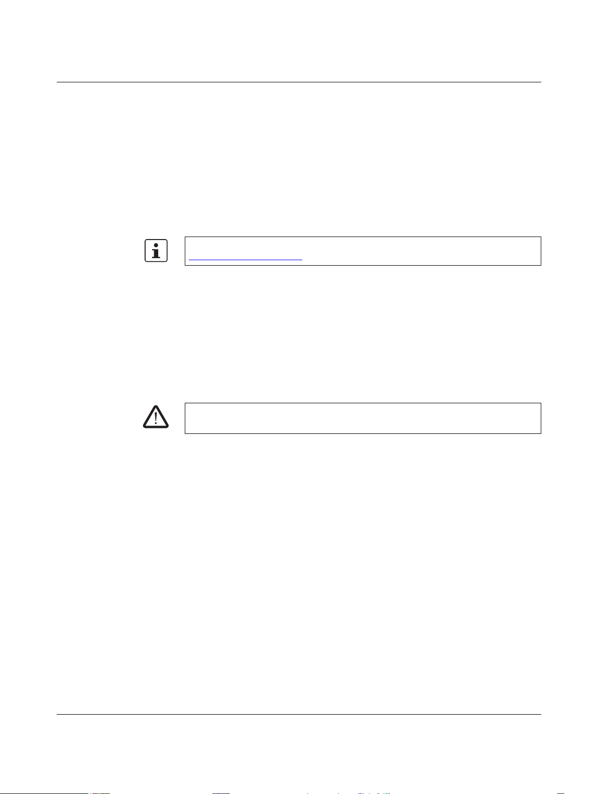
• The following page opens in the browser.
Figure 3-1 Login window
This page protects the area in web-based management where router settings are modified.
To log into the router, click on “Login”. You need the user name and the password.
– User name: admin
– Password: admin
For security reasons, we recommend you change the password during initial configuration (see “User (password change)” on page 85).
There are two user levels:
– user: read-only access to the “Device Information” menu item
– admin: full access to all areas
107025_en_01 PHOENIX CONTACT 19 / 146

TC ROUTER ... 3G/4G
3.3 Device information (viewing the device status)
You can also access this page with the user login. The page displays information about the
hardware, software, and status of the router.
3.3.1 Hardware
Figure 3-2 Device information, Hardware
Device information, Hardware
Hardware information Address Address of the manufacturer
Internet Website address of the manufacturer
Ty p e Order designation of the router
Order No. Order number of the router
Serial number Serial number of the router
Hardware Hardware version of the router
Release version Release version of the router software
Operating system Operating system version
Web-based
management
MAC address LAN MAC address for unique identification of an Ethernet device in
Radio engine Type of radio engine used
Radio firmware Firmware version of the radio engine
IMEI IMEI = International Mobile Station Equipment Identity
Web-based management version
a computer network
15-digit serial number that can be used to clearly identify each
mobile network device
20 / 146
PHOENIX CONTACT 107025_en_01

Configuration via web-based management
3.4 Status
The current status information about the mobile network and the network connections is displayed here.
3.4.1 Radio
Figure 3-3 Status, Radio
Device information, Status, Radio
Radio status Provider Provider name
Network status Status of the mobile network
– Registered home: logged in to the provider's home net-
work
– Roaming: dial-in via an external mobile network
– Waiting for PIN: enter the PIN.
– Waiting for PUK: SIM card locked because an incorrect
PIN was entered three times, PUK entry required
– Wrong PIN: wrong PIN stored in device
– No SIM card: SIM card not inserted
– Busy: radio engine starting
– Power off: radio engine switched off
Signal level Signal strength as a dBm value and bar
107025_en_01 PHOENIX CONTACT 21 / 146

TC ROUTER ... 3G/4G
Device information, Status, Radio [...]
Packet data – Offline: no packet data connection in the mobile network
IMSI IMSI = International Mobile Subscriber Identity, number used
Local area code Area code in the mobile network
Cell ID Unique mobile phone cell ID
– GPRS online: active packet data connection in the
mobile network via GPRS. GPRS is a GSM service which
provides packet-based wireless access for mobile GSM
users.
– EDGE online: active packet data connection in the mo-
bile network via EDGE. EDGE is a further development of
the GPRS data service and has a higher data transmis-
sion speed.
– UMTS online: active packet data connection in the 3G
mobile network via UMTS.
– HSDPA/UPA online: active packet data connection in
the 3G mobile network via HSDPA/UPA. HSDPA/UPA is
a further development of the UMTS network with a higher
data transmission speed.
– LTE online: active high-speed packet connection in the
4G mobile network via LTE
to clearly identify the user of a network
22 / 146
PHOENIX CONTACT 107025_en_01
Configuration via web-based management
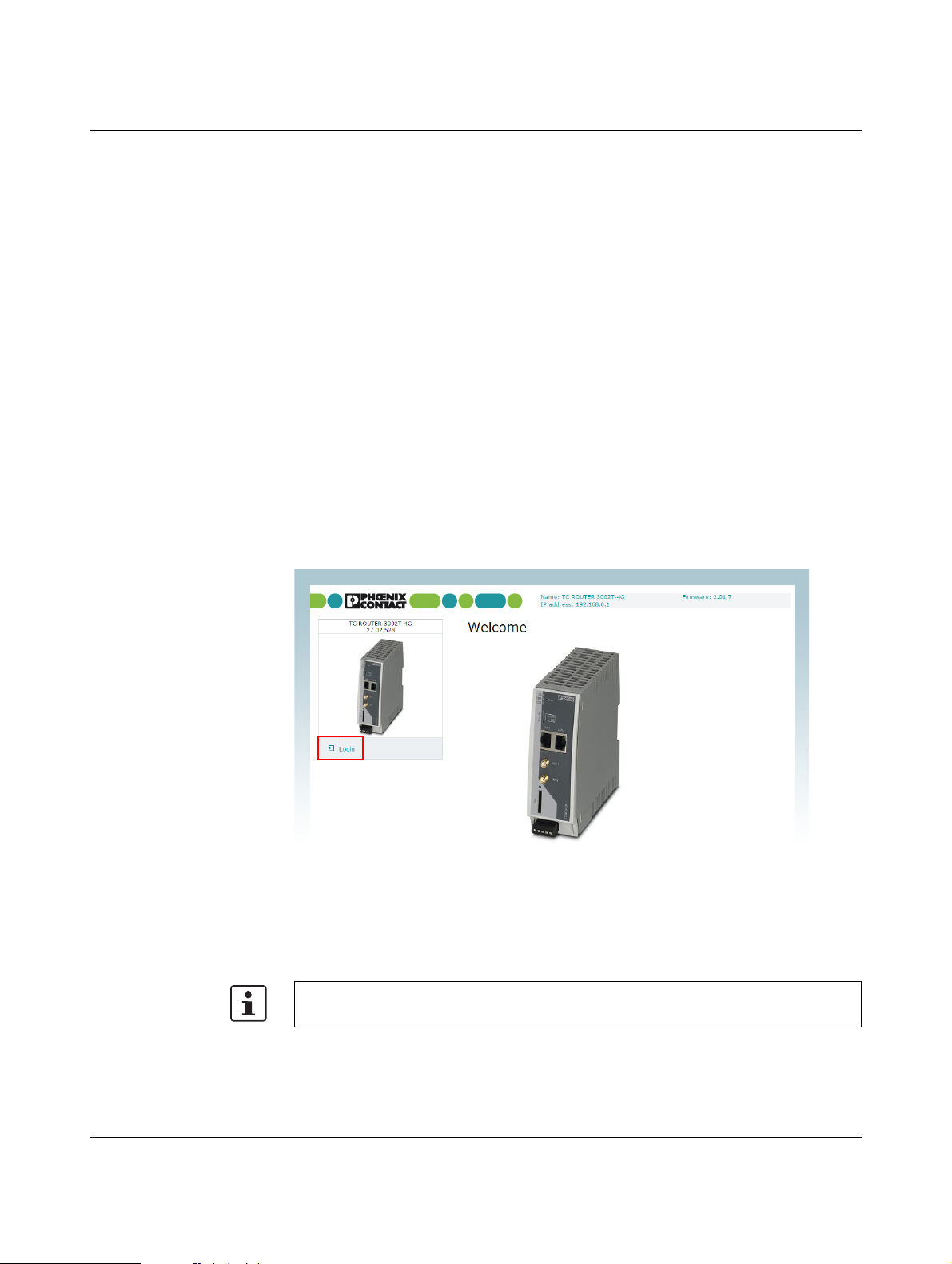
3.4.2 Network connections
This page displays status information about the local Ethernet interface and the packet data
interface in the mobile network.
Figure 3-4 Status, Network connections
Status, Network connections
Network connections
Wireless network Link – TCP/IP connected: active packet data connection in the
Local network LAN 1/2 – connected: LAN 1/2 connected
mobile network. You can transmit data via TCP/IP.
– VPN connected: active VPN connection in the mobile
network. You can transmit encrypted data.
– not connected: no packet data connection in the mobile
network, no data transmission
IP address IP address assigned by the provider
Netmask Netmask assigned by the provider
DNS server IP address of the DNS server
Sec. DNS server IP address of the alternative DNS server
Expires Time after which the IP settings assigned by the provider
expire (IP address, netmask, DNS server).
RX bytes Sum of data received since last login to the mobile network
TX bytes Sum of data sent since last login to the mobile network
– not connected: LAN 1/2 not connected
IP address Current Ethernet IP address
Netmask Netmask of the local Ethernet network
107025_en_01 PHOENIX CONTACT 23 / 146

TC ROUTER ... 3G/4G
3.4.3 I/O status
This page shows current status information and the configuration of the inputs and outputs.
Figure 3-5 Status, I/O status
3.4.4 Routing table
This page shows all entries of the routing table.
Figure 3-6 Status, Routing table
24 / 146
PHOENIX CONTACT 107025_en_01

Configuration via web-based management
3.4.5 DHCP leases
This page shows the IP addresses that the mobile router has currently assigned to the
DHCP clients.
Figure 3-7 Status, DHCP leases
3.4.6 System info
This page shows the current system utilization.
Figure 3-8 Status, System info
107025_en_01 PHOENIX CONTACT 25 / 146

TC ROUTER ... 3G/4G
3.5 Local network (local network setup)
3.5.1 IP configuration (connection setup)
The connection from the router to the local Ethernet network can be set up here. You can
modify the IP configuration, e.g., the IP address, the subnet mask, and the type of address
assignment.
Confirm your changes to the IP configuration with “Apply”. The changes only take effect
after a restart.
Figure 3-9 Local network, IP configuration
Local network, IP configuration
IP configuration
Current address IP address Current IP address of the router
Alias addresses Using alias addresses, you can assign up to 8 additional IP
Computers that are connected to the LAN interfaces access
the router using this address. You can use the reset button to
reset the IP address to the default address 192.168.0.1 (see
“Resetting the router” on page 17).
Subnet mask Subnet mask for the current IP address
Type of the IP address
assignment
– Static (default): the IP address is assigned permanently
(fixed IP).
– DHCP: when the router is started, the IP address and the
subnet mask are assigned dynamically by a DHCP serv-
er.
addresses to the router. This means that the router can be accessed from various subnetworks. Click on “New” and enter
the desired IP address and subnet mask.
26 / 146
PHOENIX CONTACT 107025_en_01

Configuration via web-based management
3.5.2 DHCP server
You can use the Dynamic Host Configuration Protocol (DHCP) to assign the set network
configuration to the devices. The devices must be connected directly to the router.
Figure 3-10 Local network, DHCP server
Local network, DHCP server
DHCP server DHCP server – Enabled: router acts as the DHCP server
Domain name Domain name that will be distributed via DHCP
Lease time (d,h,m,s) Time for which the network configuration assigned to the client
is valid
The client should renew its assigned configuration shortly before this time expires. Otherwise it may be assigned to other
computers.
Dynamic IP address
allocation
Dynamic IP address pool: when the DHCP server and the dynamic IP address pool have been activated, you can specify
the network parameters to be used by the client.
Start of IP range Start of DHCP area: the start of the address area from which
the DHCP server should assign IP addresses to locally connected devices.
End of IP range End of DHCP area: the end of the address area from which the
DHCP server should assign IP addresses to locally connected
devices.
107025_en_01 PHOENIX CONTACT 27 / 146

TC ROUTER ... 3G/4G
Local network, DHCP server [...]
Static IP address allocation Static assignment based on the MAC address: the static IP of
the client to which the MAC address should be assigned.
Client MAC address MAC of the client with dashes
Client IP address Client IP address
Static assignments must not overlap with the dynamic IP
address pool.
Do not use one IP address in multiple static assignments,
otherwise this IP address will be assigned to multiple MAC
addresses.
3.5.3 Static routes (redirection of data packets)
With local static routes, you can specify alternative routes for data packets from the local
network via other gateways in higher-level networks. You can define up to eight static
routes.
If the entries for the network and gateway are logically incorrect, the incorrect entries will be
displayed with a red frame.
Figure 3-11 Local network, Static routes
Local network, Static routes
Local static routes Network Network in CIDR format, see “CIDR (Classless Inter-Domain
Routing)” on page 136
Gateway Gateway via which this network can be accessed
28 / 146
PHOENIX CONTACT 107025_en_01

Configuration via web-based management
3.6 Wireless network (mobile network settings)
You can integrate remote stations into an IP network, e.g., the Internet, via a mobile network
connection. The mobile network connection and frequencies can be configured here.
3.6.1 Radio setup
Figure 3-12 Wireless network, Radio setup
Wireless network, Radio setup
Radio setup Frequency GSM frequency range in which the router should operate
UMTS freq. Frequency range for UMTS in which the router should operate
In addition, you can deactivate UMTS: “UMTS off”
LTE band Frequency range for LTE in which the router should operate
In addition, you can deactivate LTE: “LTE off”
Provider timeout Period of time after which the radio engine restarts in the event
of the failure or unavailability of the mobile network (in minutes)
Daily relogin – Disabled: daily login deactivated
– Enabled: daily login activated
Time Time at which the router logs out of the mobile network under
controlled conditions and logs in again.
107025_en_01 PHOENIX CONTACT 29 / 146

TC ROUTER ... 3G/4G
3.6.2 SIM
Settings for the European devices (TC ROUTER ... 3G/4G)
Figure 3-13 Wireless network, SIM (Europe)
Wireless network, SIM Settings for the primary mobile network connection, Europe
SIM Country Select the country in which the router is dialing into the GSM
network. This setting limits the selection among the providers.
PIN Enter the PIN for the SIM card here. The PIN cannot be read
back, it can only be overwritten.
Roaming If roaming is activated (default), you can select a specific pro-
vider from the drop-down menu.
– Enabled: the router can also dial-in via external networks.
If “Auto” is set under “Provider”, the strongest provider is
selected. Depending on your contract, this may incur ad-
ditional costs. Alternatively, you can specify a provider.
– Disabled: roaming is deactivated and only the provider's
home network is used. If this network is unavailable, the
router cannot establish an Internet connection.
30 / 146
PHOENIX CONTACT 107025_en_01

Configuration via web-based management
Wireless network, SIM [...] Settings for the primary mobile network connection, Europe
Provider Select a provider via which the router is to establish the Inter-
net connection. The country selected under “Country” limits
the list of providers.
– Auto: the router automatically selects the provider using
the SIM card.
User name User name for packet data access. The user name and pass-
word can be obtained from your provider. This field may be left
empty if the provider does not require a special input.
Password Password for the packet data access. This field may be left
empty if the provider does not require a password.
APN The APN can be obtained from your provider.
APN (Access Point Name) is the name of a terminal point in a
packet data network. The APN enables access to an external
data network. At the same time, the APN specifies the network
to which a connection is to be established. In the case of a
public APN, the connection is usually established to the Internet. The device supports public and private APNs.
Authentication Select the protocols for logging in to the provider:
– None: the provider's APN does not require login (default).
– Refuse MSCHAP: MSCHAP is not accepted.
– CHAP only: Only CHAP is accepted.
– PAP only: Only PAP is accepted.
107025_en_01 PHOENIX CONTACT 31 / 146

TC ROUTER ... 3G/4G
Settings for the US devices (TC ROUTER 3002T-4G VZW and
TC ROUTER 3002T-4G ATT)
The devices for the American market require special APN settings.
Figure 3-14 Wireless network, SIM (US)
Wireless network, SIM Settings for the primary mobile network connection, US
SIM Country Select the country in which the router is dialing into the GSM
network. This setting limits the selection among the providers.
PIN Enter the PIN for the SIM card here. The PIN cannot be read
back, it can only be overwritten.
Roaming If roaming is activated (default), you can select a specific pro-
vider from the drop-down menu.
– Enabled: the router can also dial-in via external networks.
If “Auto” is set under “Provider”, the strongest provider is
selected. Depending on your contract, this may incur ad-
ditional costs. Alternatively, you can specify a provider.
– Disabled: roaming is deactivated and only the provider's
home network is used. If this network is unavailable, the
router cannot establish an Internet connection.
32 / 146
PHOENIX CONTACT 107025_en_01

Configuration via web-based management
Only use "overwrite APN" if the default APN of your
provider changed and the router does not adapt
automatically.
Contact your provider if you have accidentally overwritten the default APN.
Wireless network, SIM [...] Settings for the primary mobile network connection, US
Provider Select a provider via which the router is to establish the Inter-
net connection. The country selected under “Country” limits
the list of providers.
– Auto: the router automatically selects the provider using
the SIM card.
User name User name for packet data access. The user name and pass-
word can be obtained from your provider. This field may be left
empty if the provider does not require a special input.
Password Password for the packet data access. This field may be left
empty if the provider does not require a password.
APN APN (Access Point Name) is the name of a terminal point in a
packet data network. The APN enables access to an external
data network. At the same time, the APN specifies the network
to which a connection is to be established. In the case of a
public APN, the connection is usually established to the Internet. The device supports public and private APNs.
– managed Internet APN: default, no manual input
The device autonomously logs in to the network. The APN
is set automatically. When the router has logged in to the
network, the standard APN used is displayed.
– managed application APN (only Verizon Wireless):
enter an application APN. The standard APN remains
stored in the device.
– customer APN: enter a customer-specific APN. The
standard APN remains stored in the device.
– overwrite APN: the standard APN will be deleted if you
enter your APN here. This is only possible after the router
has successfully made a connection with the mobile net-
work by using the default setting (managed Internet APN).
Authentication Select the protocols for logging in to the provider:
– None: the provider's APN does not require login (default).
– Refuse MSCHAP: MSCHAP is not accepted.
– CHAP only: Only CHAP is accepted.
– PAP only: Only PAP is accepted.
107025_en_01 PHOENIX CONTACT 33 / 146

TC ROUTER ... 3G/4G
3.6.3 SMS configuration (SMS settings)
You can operate the device remotely via SMS.
• Open “Wireless network, SMS configuration”. Activate “SMS control” and enter the
“SMS password”. The password can contain up to seven alphanumeric characters.
In addition, the device can forward received SMS messages to a recipient as a UDP packet
via Ethernet.
• Activate the “SMS forward” function.
• Enter the recipient IP address and port with which you would like to communicate. The
default value for the server is port 1432. Alternatively, incoming SMS messages can be
accessed from the local Ethernet network via XML and socket server (see “Socket serv-
er” on page 75).
The received SMS is forwarded in the following format:
– origaddr = Sender telephone number
– timestamp = Time stamp of the service center in GSM 03.40 format
The SMS syntax for switching inputs, outputs, and functions contains the following information:
– Password
–Function command
– Additional subcommands
Table 3-1 Supported function commands
Function command Description
SET:<sub_cmd> General command for starting functions (ON), must be supple-
mented with subcommand
CLR:<sub_cmd> General command for stop functions (OFF), must be supple-
mented with subcommand
SEND:STATUS Query status of the mobile router
RESET Reset alarms
REBOOT Restart mobile router
Table 3-2 Subcommands <sub_cmd> for the function commands “SET” and “CLR”
Subcommand
Description
<sub_cmd>
GPRS Start or stop packet data connection
OUTPUT Switch output 1: ON/OFF
OUTPUT:n Switch output n: ON/OFF, n={1...4}
IPSEC Start or stop IPsec VPN 1: ON/OFF
IPSEC:n Start or stop IPsec VPN n: ON/OFF, n={1...3}
OPENVPN Start or stop VPN 1: ON/OFF
OPENVPN:n Start or stop VPN n: ON/OFF, n={1...3}
34 / 146
PHOENIX CONTACT 107025_en_01

Configuration via web-based management
Figure 3-15 Wireless network, SMS configuration
Wireless network, SMS configuration
SMS configuration SMS control – Disabled: remote operation of router via SMS not possi-
ble
– Enabled: remote operation of router via SMS activated
SMS password SMS password for remote operation
SMS forward – Disabled: not possible to forward SMS messages via
Ethernet
– Enabled: forwarding of SMS messages via Ethernet acti-
vated
Server IP address IP address to which the SMS message should be forwarded
Server port (default
Port to which the SMS message should be forwarded
1432)
Example
SMS message text for starting IPsec tunnel #2 with the password 1234:
#1234:SET:IPSEC:2
To stop this connection, you must send the following SMS message:
#1234:CLR:IPSEC:2
107025_en_01 PHOENIX CONTACT 35 / 146

TC ROUTER ... 3G/4G
3.6.4 Packet data setup
Figure 3-16 Wireless network, Packet data setup
Wireless network, Packet data setup
Packet data setup Packet data – Disabled: packet data connection deactivated
– Enabled: access enabled to
LTE / UMTS / HSPA / GPRS / EDGE
If this packet data connection is activated, there is only a virtual permanent connection to the partner. This wireless area is
not used until data is actually transmitted, e.g., via VPN tunnel.
MTU (default 1500) Maximum Transmission Unit (MTU) is the maximum packet
size, in bytes, in the mobile network
Event Event that starts the packet data connection:
– Initiate: automatic start after router boots up
– Initiate on Input #1 ... #2: manual start via switching
input
– Initiate on SMS: manual start via SMS message
– Initiate on XML: manual start via XML socket server
Manual DNS – Disabled: manual DNS setting is deactivated. The DNS
settings are received automatically from the provider.
– Enabled: manual DNS setting is enabled.
DNS server IP address of the primary DNS server in the mobile network
Sec. DNS server IP address of the alternative DNS server in the mobile network
36 / 146
PHOENIX CONTACT 107025_en_01

Configuration via web-based management
3.6.5 Wireless static routes (redirection of data packets)
With static routes, you can specify alternative routes for data packets in the mobile network.
If the entries for the network and gateway are logically incorrect, the incorrect entries will be
displayed with a red frame.
Figure 3-17 Wireless network, Wireless static routes
Wireless network, wireless static routes
Wireless static routes Network The network in CIDR format, see “CIDR (Classless Inter-Do-
main Routing)” on page 136
Gateway Gateway via which this network can be accessed
107025_en_01 PHOENIX CONTACT 37 / 146

TC ROUTER ... 3G/4G
3.6.6 DynDNS (address management via dynamic DNS)
Each mobile router is dynamically assigned an IP address by the provider. The address
changes from session to session.
If the mobile router is to be accessed via the Internet, you can specify a fixed host name with
the help of a DynDNS provider for the dynamic IP address. The router can in the future be
accessed via this host name.
Check whether your mobile network provider supports dynamic DNS in the mobile network.
Figure 3-18 Wireless network, DynDNS
Wireless network, DynDNS
DynDNS setup Status – Disabled: DynDNS client deactivated
– Enabled: DynDNS client activated
DynDNS provider Select the name of the provider with whom you are registered,
e.g., DynDNS.org, TZO.com, dhs.org
DynDNS user name User name for your DynDNS account
DynDNS password Password for your DynDNS account
DynDNS host name Host name that was specified for this router with the DynDNS
service
The router can be accessed via this host name.
38 / 146
PHOENIX CONTACT 107025_en_01

Configuration via web-based management
3.6.7 Connection check (connection monitoring)
Connection monitoring enables you to check whether the packet data connection in the mobile network is functioning correctly. In order to maintain the packet data connection in the
mobile network, connection monitoring also acts as a Keep Alive function.
Figure 3-19 Wireless network, Connection check
Wireless network, connection check
Connection check Status – Disabled: connection monitoring of the packet data con-
nection is deactivated (default)
– Enabled: connection monitoring of the packet data con-
nection is activated
Host #1 ... #3 IP address or host name of the reference point for connection
monitoring
Source – Local: the local network interface sends the connection
monitoring IP packets with the IP address of the local in-
terface (LAN).
– Wireless network: the mobile network interface sends
the connection monitoring IP packets with the IP address
assigned by the provider.
Check every Check interval in minutes
Max. retry Number of times to retry until the configured action is per-
formed
107025_en_01 PHOENIX CONTACT 39 / 146

TC ROUTER ... 3G/4G
Wireless network, connection check [...]
Activity – Reboot: restart router
– Reconnect: re-establish packet data connection
– Relogin: shut down mobile network interface and restart
by logging into the mobile network again.
– None: no action
As an option, you can configure information regarding the
status of connection monitoring via a switching output.
40 / 146
PHOENIX CONTACT 107025_en_01

Configuration via web-based management
3.6.8 Monitoring
Monitoring records mobile network parameters. You can use the function temporarily for
startup or troubleshooting. The function is not intended for permanent use. All parameters
are stored in a separate log file: “logradio.txt”. At the end of the monitoring period, monitoring must be disabled.
Figure 3-20 Wireless network, Monitoring
Wireless network, Monitoring
Monitoring Monitoring – Disabled: mobile network monitoring deactivated (de-
fault)
– Enabled: mobile network monitoring activated
Log duration Monitoring duration in hours, we recommend a maximum of
30 hours
Log interval Monitoring interval in minutes (at least one minute)
Ping host IP address or host name of the reference point for monitoring
Clear Clear log file in the router for a new monitoring session
View View current log file
Save Save log file on local computer
107025_en_01 PHOENIX CONTACT 41 / 146

TC ROUTER ... 3G/4G
Structure of the “logradio.txt” log file:
Date and time
Network status creg=
0 Not logged in, not searching for cellular network
1 Logged in, home network
2 Not logged in, searching for cellular network
3 Not logged in, login rejected
4 Status unknown
5 Logged in, external network
Reception strength rssi=
0 -113 dBm or worse
1-111dBm
2...30 -109 dBm ... -53 dBm
31 -51 dBm or better
Packet data connection packet=
0 OFFLINE
1ONLINE
2GPRS ONLINE
3EDGE ONLINE
4WCDMA ONLINE
5WCDMA HSDPA ONLINE
6WCDMA HSUPA ONLINE
7 WCDMA HSDPA+HSUPA ONLINE
8LTE ONLINE
42 / 146
Location lac= Location Area Code
ci= mobile phone cell ID
Current own IP address myip=
Reference IP ping=
Ping times in msd round-trip min/avg/max= (minimum/average/maximum)
PHOENIX CONTACT 107025_en_01

Configuration via web-based management
3.7 Network security (security settings)
3.7.1 General setup
General settings for network security can be made on this page.
Figure 3-21 Network security, General setup
Network security, general setup
Network security setup Traffic forwarding – Disabled: port forwarding from the mobile network to the
local network is deactivated (default)
– Port forwarding: port forwarding from the mobile net-
work to the local network is activated
– Exposed host: forwarding of all data traffic from the mo-
bile network to an Ethernet device in the local network is
activated. This access cannot be restricted via the fire-
wall in the mobile router.
Block outgoing
netbios
Drop invalid packets The firewall of the mobile router can filter and drop invalid or
If Windows-based systems are installed in the local network,
NetBIOS requests can result in data traffic and the associated
costs, where applicable.
– Disabled: outgoing NetBIOS requests are permitted.
– Enabled: outgoing NetBIOS requests are blocked (de-
fault).
damaged IP packets.
– Disabled: invalid IP packets are also sent.
– Enabled: invalid IP packets are dropped (default).
107025_en_01 PHOENIX CONTACT 43 / 146

TC ROUTER ... 3G/4G
Network security, general setup [...]
External ping (ICMP) A ping can be used to check whether a device in an IP network
External web-based
management via
HTTPS
External NAT
(Masquerade)
Device access via SSH This option can be used to specify whether the router can be
External access via
SSH
can be accessed. During normal operation, responding to external ping requests results in data traffic and its associated
costs, where applicable.
– Disabled: if a ping request is sent from the external IP
network to the router, it is ignored (default).
– Enabled: if a ping request is sent from the external IP net-
work to the router, it is sent back.
Select whether the router may be configured via the mobile
network or the external network using the web-based management (WBM).
– Disabled: external configuration via WBM is not possible.
Set this option if you wish to configure and maintain the
router locally (default).
– Enabled: the router can be configured externally via
WBM. Remote maintenance of the router is therefore pos-
sible. The router can be accessed from any external IP
address. Access cannot be restricted via the firewall.
For outgoing data packets, the router can rewrite the specified
sender IP addresses from its internal network to its own external address. This method is used if the internal addresses
cannot be routed externally. This is the case, for example, if a
private address area such as 192.168.x.x is used. This
method is referred to as IP masquerading.
– Disabled: IP masquerading is deactivated
– Enabled: IP masquerading is activated. You can commu-
nicate via the Internet from a private, local network (de-
fault).
accessed via the SSH service.
– Disabled: the SSH service is not available. No access to
the router via SSH (default).
– Enabled: access to the router via the SSH service is pos-
sible, from the local network or via a VPN tunnel.
This option can be used to specify whether the router can be
accessed via the mobile network or the external network via
the SSH service.
– Disabled: the SSH service is not available. No external
access to the router via SSH (default)
– Enabled: external access to the router via the SSH ser-
vice is possible, from the local network or via a VPN tun-
nel.
44 / 146
PHOENIX CONTACT 107025_en_01

Configuration via web-based management
3.7.2 Firewall (definition of firewall rules)
The device includes a stateful packet inspection firewall. The connection data of an active
connection is recorded in a database (connection tracking). Rules therefore only have to be
defined for one direction. This means that data from the other direction of the relevant connection, and only this data, is automatically allowed through.
The firewall is active by default upon delivery. It blocks incoming data traffic and only permits
outgoing data traffic.
If multiple firewall rules are defined, these are queried starting from the top of the list of
entries until an appropriate rule is found. This rule is then applied.
If the list of rules contains further subsequent rules that could also apply, these rules are
ignored.
The device supports a maximum of 32 rules for incoming data traffic and 32 rules for outgoing data traffic.
Figure 3-22 Network security, Firewall
Network security, firewall
Firewall Lists the firewall rules that have been set up. They apply for incoming data links that have
been initiated externally.
Incoming traffic Protocol TCP, UDP, ICMP, all
From IP / To IP 0.0.0.0/0 means all IP addresses. To specify an address area,
use CIDR format (see “CIDR (Classless Inter-Domain Rout-
ing)” on page 136).
From port / To port (Only evaluated for TCP and UDP protocols)
– any: any port
– startport-endport: a port range (e.g., 110 ... 120)
107025_en_01 PHOENIX CONTACT 45 / 146

TC ROUTER ... 3G/4G
If no rule is defined, all outgoing connections are prohibited (excluding VPN).
Network security, firewall [...]
Outgoing traffic Lists the firewall rules that have been set up. They apply for outgoing data links that have
Action – Accept: the data packets may pass through.
– Reject: the data packets are sent back. The sender is in-
formed of their rejection.
– Drop: the data packets are blocked. They are discarded,
which means that the sender is not informed of their
whereabouts.
Log For each individual firewall rule you can specify whether the
event is to be logged if the rule is applied.
– Yes: event is logged.
– No: event is not logged (default).
New – New: add a new firewall rule below the last rule.
– Delete: delete rule from the table.
The arrows can be used to move the respective rule one row
up/down.
been initiated internally in order to communicate with a remote peer.
Default: a rule is defined by default that allows all outgoing connections.
Protocol TCP, UDP, ICMP, all
From IP / To IP 0.0.0.0/0 means all IP addresses. To specify an address area,
use CIDR format (see “CIDR (Classless Inter-Domain Rout-
ing)” on page 136).
From port / To port (Only evaluated for TCP and UDP protocols)
– any: any port
– startport-endport: a port range (e.g., 110 ... 120)
Action – Accept: the data packets may pass through.
– Reject: the data packets are sent back. The sender is in-
formed of their rejection.
– Drop: the data packets are blocked. They are discarded,
which means that the sender is not informed of their
whereabouts.
Log For each individual firewall rule you can specify whether the
event is to be logged if the rule is applied.
– Yes: event is logged.
– No: event is not logged (default).
New – New: add a new firewall rule below the last rule.
– Delete: delete rule from the table.
The arrows can be used to move the respective rule one row
up/down.
46 / 146
PHOENIX CONTACT 107025_en_01

Configuration via web-based management
3.7.3 SNMP Firewall
Th e de vice ha s an additi ona l firew all for SNM P co nnecti ons . It can be u sed to r est ric t SNM P
access. The firewall is active by default upon delivery. It blocks external access (incoming
external traffic) and only allows access from the local network (incoming local traffic).
The device supports a maximum of 32 rules for local access and 32 rules for external access.
Figure 3-23 Network security, SNMP Firewall
Network security, SNMP Firewall
SNMP Firewall From IP 0.0.0.0/0 means all IP addresses. To specify an address area,
use CIDR format (see “CIDR (Classless Inter-Domain Rout-
ing)” on page 136).
Action – Accept: the data packets may pass through.
– Reject: the data packets are sent back. The sender is in-
formed of their rejection.
– Drop: the data packets are blocked. They are discarded,
which means that the sender is not informed of their
whereabouts.
Log For each individual firewall rule you can specify whether the
event is to be logged if the rule is applied.
– Yes: event is logged.
– No: event is not logged (default).
107025_en_01 PHOENIX CONTACT 47 / 146

TC ROUTER ... 3G/4G
3.7.4 IP and port forwarding (port forwarding setup)
The table contains the rules defined for IP and port forwarding. The device has one IP address, which can be used to access the device externally. For incoming data packets, the
device can convert the specified sender IP addresses to internal addresses. This technique
is referred to as NAT (Network Address Translation). Using the port number, the data packets can be redirected to the ports of internal IP addresses.
The device supports a maximum of 32 rules for port forwarding.
Figure 3-24 Network security, IP and port forwarding
Network security, IP and port forwarding
IP and port forwarding Protocol TCP, UDP, ICMP
From IP 0.0.0.0/0 means all IP addresses. To specify an address area,
use CIDR format (see “CIDR (Classless Inter-Domain Rout-
ing)” on page 136).
In port / To port Only evaluated for TCP and UDP protocols
– any: any port
– startport-endport: a port range (e.g., 110 ... 120)
To I P IP address from the local network, incoming packets are for-
warded to this address
Masq For each individual rule you can specify whether IP masquer-
ading is to be used.
– Yes: IP masquerading is activated, incoming packets
from the Internet are given the IP address of the router. A
response via the Internet is possible, even without a de-
fault gateway.
– No: a response via the Internet is only possible with the
default gateway (default).
48 / 146
PHOENIX CONTACT 107025_en_01

Network security, IP and port forwarding [...]
Log For each individual rule, you can specify whether the event is
New – New: add a new firewall rule below the last rule.
Configuration via web-based management
to be logged if the rule is applied.
– Yes: event is logged.
– No: event is not logged (default).
– Delete: delete rule from the table.
The arrows can be used to move the rule one row up or down.
107025_en_01 PHOENIX CONTACT 49 / 146

TC ROUTER ... 3G/4G
3.7.5 Exposed host (server setup)
With this function, the router forwards all received external packets that do not belong to an
existing connection to an IP address in the LAN. The device can therefore be accessed directly from the Internet as an “exposed host”. You can use the device as a server.
Figure 3-25 Network security, Exposed host
Network security, exposed host
Exposed host Local exposed host IP address of the exposed host (server)
Allow external access
from
IP addresses for incoming data links
0.0.0.0/0 means all IP addresses. To specify an address area,
use CIDR format (see “CIDR (Classless Inter-Domain Rout-
ing)” on page 136).
Masquerade traffic to
exposed host
Specify whether IP masquerading is to be used.
– Enabled: IP masquerading is activated, incoming pack-
ets from the Internet are given the IP address of the router.
A response via the Internet is possible, even without a de-
fault gateway.
– Disabled: a response via the Internet is only possible with
the default gateway (default).
Log traffic to exposed
host
Specify whether IP connections are logged.
– Enabled: IP connections are logged.
– Disabled: IP connections are not logged (default).
50 / 146
PHOENIX CONTACT 107025_en_01

Configuration via web-based management
3.7.6 Masquerading
For certain networks you can specify whether IP masquerading is to be used. If IP masquerading is activated, all incoming packets from the Internet are given the IP address of the
router. The response in the configured networks is possible even without a default gateway.
The device supports a maximum of 16 rules for IP masquerading.
Figure 3-26 Network security, Masquerading
Network security, masquerading
Masquerading From IP 0.0.0.0/0 means all IP addresses. To specify an address area,
use CIDR format (see “CIDR (Classless Inter-Domain Rout-
ing)” on page 136).
107025_en_01 PHOENIX CONTACT 51 / 146

TC ROUTER ... 3G/4G
3.8 VPN
Requirements for a VPN connection
A general requirement for a VPN connection is that the IP addresses of the VPN partners
are known and can be accessed. The device supports up to three IPsec connections and
up to two OpenVPN connections. When a VPN connection is active, the VPN LED on the
device is illuminated.
In order to successfully establish an IPsec connection, the VPN peer must support IPsec
with the following configuration:
– Authentication via X.509 certificate or pre-shared secret key (PSK)
– Diffie-Hellman group 2 or 5
– 3DES or AES encryption
– MD5 or SHA-1 hash algorithms
– Tunnel mode
–Quick mode
–Main mode
– SA lifetime (one second to 24 hours)
The following functions are supported for OpenVPN connections:
– OpenVPN Client
–TUN device
– Authentication via X.509 certificate or pre-shared secret key (PSK)
– Static key
– TCP and UDP transmission protocol
– Keep Alive
52 / 146
PHOENIX CONTACT 107025_en_01

Configuration via web-based management
3.8.1 IPsec connections (IPsec connection setup)
IPsec (Internet Protocol Security) is a secure VPN standard that is used for communication
via IP networks.
Figure 3-27 VPN, IPsec, Connections
VPN, IPsec, Connections
IPsec connections Monitor DynDNS Activate this function to check accessibility.
– If the VPN peer does not have a fixed IP address
– if a DynDNS name is used as the “Remote host”.
Check interval Enter the check interval in seconds.
Enabled – Yes: VPN connection activated
– No: VPN connection deactivated
Name Assign a descriptive name to each VPN connection. The VPN
connection can be freely named or renamed.
Settings Click on Edit to specify the settings for IPsec (see Page 54).
IKE Internet Key Exchange protocol for automatic key manage-
ment for IPsec
Click on Edit to specify the settings for IKE (see Page 58).
107025_en_01 PHOENIX CONTACT 53 / 146

TC ROUTER ... 3G/4G
Settings, Edit
Figure 3-28 VPN, IPsec, Connections, Settings, Edit
VPN, IPsec, Connections, Settings, Edit
IPsec connection settings Name Name of the VPN connection entered under “IPsec connec-
tions“
VPN – Yes: VPN connection activated
– No: VPN connection deactivated
Remote host IP address or URL of the peer to which (or from which) the tun-
nel will be created.
“Remote host” is only used if “Initiate” has been selected
under “Remote connection” (the router establishes the connection).
If “Remote connection” is set to “Accept”, the value “%any” is
set internally for “Remote host”. It therefore waits for a connection.
54 / 146
PHOENIX CONTACT 107025_en_01

VPN, IPsec, Connections, Settings, Edit [...]
The procedure for creating an X.509 certificate
is described in Section “Creating certificates”
on page 101.
Authentication X.509 remote certificate: authentication method with X.509
Remote certificate Certificate the router uses to authenticate the VPN peer (re-
Local certificate Certificate used by the router to authenticate itself to the VPN
Remote ID Default: empty field
Configuration via web-based management
certificate
With the X.509 certificate option, each VPN device has a private secret key and a public key. The certificate contains additional information about the certificate's owner and the certification authority (CA).
Preshared secret key (PSK): authentication method
With a preshared secret key, each VPN device knows one
shared private key, one password. Enter this shared key in the
“Preshared Secret Key” field.
mote certificate, .pem).
The selection list contains the certificates that have been
loaded on the router (see “IPsec certificates (certificate up-
load)” on page 60).
peer (machine certificate, PKCS#12)
The selection list contains the certificates that have been
loaded on the router (see “IPsec certificates (certificate up-
load)” on page 60).
The Remote ID can be used to specify the name the router
uses to identify itself to the partner. The name must match the
data in the router certificate. If the field is left empty, the data
from the certificate is used.
Valid values:
– No entry (default). The “Subject” entry (previously Distin-
guished Name) in the certificate is used.
– Subject entry in the certificate
– One of the “Subject Alternative Names”, if they are listed
in the certificate. If the certificate contains “Subject Alter-
native Names”, these are specified under “Valid values”.
These can include IP addresses, host names with “@”
prefix or e-mail addresses, for example.
107025_en_01 PHOENIX CONTACT 55 / 146

TC ROUTER ... 3G/4G
VPN, IPsec, Connections, Settings, Edit [...]
Local ID Default: empty field
Virtual remote
address
Address remote network
Address local network IP address/subnet mask of the local network
Connection NAT – None: no NAT within the VPN tunnel (default)
NAT to local network Enter the real IP address area for the local network here. Using
The “Local ID” can be used to specify the name the router uses
to identify itself to the peer.
For additional information, see “Remote ID“.
Virtual address of software VPN clients that are to establish
the VPN connection. If your software VPN client requires this
virtual address, activate this function.
IP address/subnet mask of the remote network to which the
VPN connection is to be established
Specify the address of the network or computer which is connected locally to the router here.
– “NAT to local network” set to “None” (default)
Actual IP address or subnet mask of the local network.
Specify the address of the network that is connected lo-
cally to the router here.
– “Local 1:1 NAT” and “Remote masquerading” activated
This virtual IP address/subnet mask enables the IP ad-
dresses for the remote network to be accessed through
the VPN tunnel. You must enter the same settings as the
remote network on the remote VPN router.
– Local 1:1 NAT: virtual IP addresses are used for commu-
nication via a VPN tunnel. These addresses are linked to
the real IP addresses for the set network that has been
connected. The subnet mask remains unchanged.
– Remote masquerading: as with “Local 1:1 NAT”, virtual
IP addresses are used for communication via a VPN tun-
nel. In addition, the sender IP address (source IP) is re-
placed with the IP address of the router for all incoming
packets via a VPN tunnel. Devices in the local network
that cannot use a default gateway can therefore be ac-
cessed via a VPN tunnel.
this address area, the local network can be accessed from the
remote network via 1:1 NAT. You can use this function, for example, to access two machines with the same IP address via
a VPN tunnel.
56 / 146
PHOENIX CONTACT 107025_en_01

VPN, IPsec, Connections, Settings, Edit [...]
Remote connection Side from which the connection can be established
Configuration via web-based management
– Initiate: VPN connection is started by the router.
– Accept: VPN connection is initiated by the peer.
Additional settings:
– Initiate on Input...: VPN tunnel is started or stopped via
a digital input.
– Initiate on SMS: VPN tunnel is started via SMS. You
must also specify the number of minutes until the VPN
tunnel is to be stopped via Autoreset.
– Initiate on call: VPN tunnel is started via a call. You must
also specify the number of minutes until the VPN tunnel is
to be stopped via Autoreset.
– Initiate on XML: VPN tunnel is started or stopped via an
XML command via socket server.
107025_en_01 PHOENIX CONTACT 57 / 146

TC ROUTER ... 3G/4G
IKE, Edit
Figure 3-29 VPN, IPsec, Connections, IKE, Edit
VPN, IPsec, Connections, IKE, Edit
IPsec - Internet Key
Name Name of the VPN connection entered under ““IPsec connec-
Exchange settings
IKE protocol Select an IKE version.
Phase 1 ISAKMP SA
Key exchange
ISAKMP SA
encryption
ISAKMP SA hash Leave this set to SHA-1/MD5. It then does not matter whether
tions“
– initiate IKEv2: IKEv2 is pref err ed. A switc h ba ck to IK Ev1
takes place in case of an erroneous connection attempt.
Encryption algorithm
Internet Security Association and Key Management Protocol
(ISAKMP) is a protocol for creating Security Associations (SA)
and exchanging keys on the Internet.
AES128 is preset as default.
The following generally applies: the more bits an encryption algorithm has (specified by the appended number), the more
secure it is. The relatively new AES-256 method is therefore
the most secure, however it is still not used that widely. The
longer the key, the more time-consuming the encryption procedure.
the peer works with MD5 or SHA-1.
58 / 146
PHOENIX CONTACT 107025_en_01

VPN, IPsec, Connections, IKE, Edit [...]
ISAKMP SA lifetime The keys of an IPsec connection are renewed at defined inter-
Phase 2 IPsec SA
Data exchange
IPsec SA encryption See “ISAKMP SA encryption“
IPsec SA hash See “ISAKMP SA encryption“
IPsec SA lifetime Lifetime in seconds of the keys agreed for IPsec SA
Perfect forward
secrecy (PFS)
DH/PFS group Key exchange procedure, defined in RFC 3526 – More Modu-
Dead peer detection If the peer supports the Dead Peer Detection (DPD) protocol,
Configuration via web-based management
vals in order to increase the difficulty of an attack on an IPsec
connection.
ISAKMP SA lifetime: lifetime in seconds of the keys agreed for
ISAKMP SA.
Default: 3600 seconds (1 hour)
The maximum lifetime is 86400 seconds (24 hours).
In contrast to Phase 1 ISAKMP SA (key exchange), the procedure for data exchange is defined here. It does not necessarily
have to differ from the procedure defined for key exchange.
Default: 28800 seconds (8 hours)
The maximum lifetime is 86400 seconds (24 hours).
– Yes: PFS activated
– No: PFS deactivated
lar Exponential (MODP) Diffie-Hellman groups for Internet
Key Exchange (IKE)
Perfect Forward Secrecy (PFS): method for providing increased security during data transmission. With IPsec, the
keys for data exchange are renewed at defined intervals. With
PFS, new random numbers are negotiated with the peer instead of being derived from previously agreed random numbers.
5/modp1536 – 2/modp1024
The following generally applies: the more bits an encryption algorithm has (specified by the appended number), the more
secure it is. The longer the key, the more time-consuming the
encryption procedure.
the relevant peers can detect whether or not the IPsec connection is still valid and whether it needs to be established
again.
Behavior in the event that the IPsec connection is aborted:
– Off: no DPD
– On: DPD activated
– in “Restart” mode for VPN Initiate
– in “Clear” mode for VPN Accept
107025_en_01 PHOENIX CONTACT 59 / 146

TC ROUTER ... 3G/4G
VPN, IPsec, Connections, IKE, Edit [...]
DPD delay Delay between requests for a sign of life
DPD timeout Duration after which the connection to the peer should be de-
3.8.2 IPsec certificates (certificate upload)
A certificate that has been loaded on the router is used to authenticate the router at the peer.
The certificate acts as an ID card for the router, which it shows to the relevant peer.
The procedure for creating an X.509 certificate is described under “CIDR (Classless Inter-
Domain Routing)” on page 136.
There are various types of certificate:
– Remote or peer certificates contain the public key used to decode the encrypted data.
– Own or machine certificates contain the private key used to encrypt the data. The pri-
vate key is kept private. A PKCS#12 file is therefore protected by a password.
– The CA certificate or root certificate is the “mother of all certificates used”. It is used to
check the validity of the certificates.
By importing a PKCS#12 file, the router is provided with a private key and the corresponding
certificate. You can load several PKCS#12 files on the router. This enables the router to
show the desired machine certificate to the peer for various connections. This can be a selfsigned or CA-signed machine certificate.
To use a certificate that is installed, the certificate must be assigned under “VPN, IPsec,
Connections, Settings, Edit“. Click on “Apply” to load the certificate onto the router.
Duration in seconds after which DPD Keep Alive requests
should be transmitted. These requests test whether the peer
is still available.
Default: 30 seconds
clared dead if there has been no response to the Keep Alive
requests.
Default: 120 seconds.
60 / 146
PHOENIX CONTACT 107025_en_01

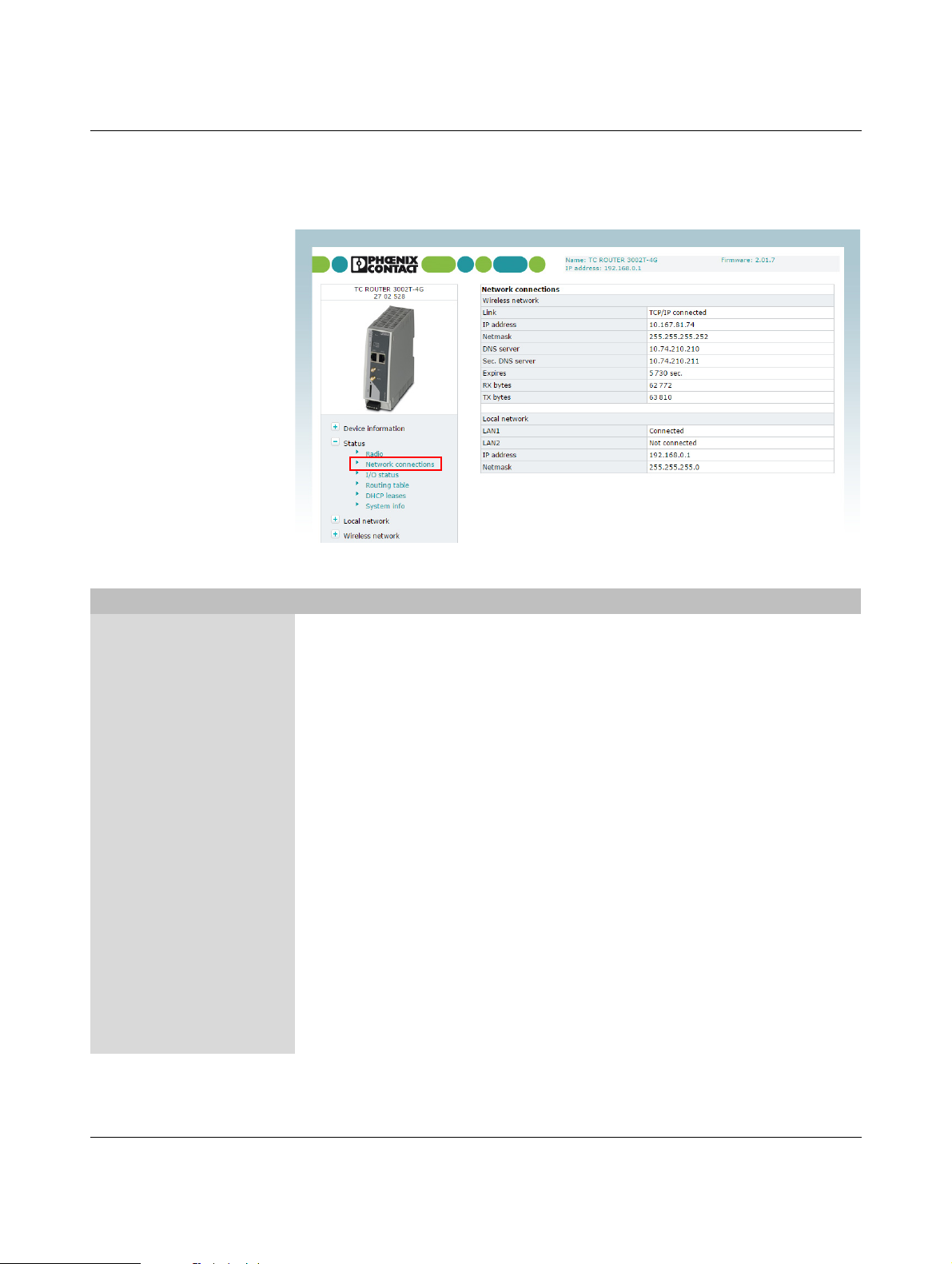
Figure 3-30 VPN, IPsec, Certificates
The procedure for creating an X.509 certificate
is described under Section 4.5, “Creating certif-
icates”.
Configuration via web-based management
VPN, IPsec, Certificates
IPsec certificates Load remote certifi-
cate (.cer .crt)
Load own PKCS#12
certificate (.p12)
Here you can upload certificates which the router can use for
authentication with the VPN peer.
– Upload: import certificate. Click on the “Browse” button to
select the certificate to be imported.
Under “VPN, IPsec, Connections, Settings, Edit“, one of
the certificates listed under “Remote certificate“ or “Local cer-
tificate“ can be assigned to each VPN connection.
Upload: import the certificate you have received from your
provider. The file must be in PKCS#12 format. Click on the
“Browse” button to select the certificate to be imported.
Under “VPN, IPsec, Connections, Settings, Edit“, one of
the certificates listed under “Remote certificate“ or “Local cer-
tificate“ can be assigned to each VPN connection.
Password: password used to protect the private key of the
PKCS#12 file. The password is assigned when the key is exported.
107025_en_01 PHOENIX CONTACT 61 / 146

TC ROUTER ... 3G/4G
VPN, IPsec, Certificates [...]
Remote certificates Overview of the imported .cer/.crt certificates of the peers
Click on “Delete” to delete a certificate.
Own certificates Overview of own imported PKCS#12 certificates
Click on “Delete” to delete a certificate.
The green ticks indicate whether the PKCS#12 file contains a
CA certificate, a machine certificate or a private key.
3.8.3 IPsec status (status of the VPN connection)
Figure 3-31 VPN, IPsec, Status
VPN, IPsec, Status
IPsec status Active IPsec
connections
62 / 146
PHOENIX CONTACT 107025_en_01
Status of the active VPN connection

Configuration via web-based management
3.8.4 OpenVPN connections (OpenVPN connection setup)
OpenVPN is a program for creating a virtual private network (VPN) via an encrypted connection. The device supports two OpenVPN connections.
Figure 3-32 VPN, OpenVPN, Connections
VPN, OpenVPN, Connections
OpenVPN connections Enabled – Yes: defined VPN connection active
– No: defined VPN connection not active
Name Assign a descriptive name to each VPN connection. The VPN
connection can be freely named or renamed.
Tu n ne l Click on “Edit” to specify the settings for OpenVPN (see “Tun-
nel, Edit” on page 64).
Advanced Click on “Edit” to specify advanced settings for OpenVPN (see
“Advanced, Edit” on page 67).
107025_en_01 PHOENIX CONTACT 63 / 146

TC ROUTER ... 3G/4G
Tunnel, Edit
Figure 3-33 VPN, OpenVPN, Connections, Tunnel, Edit
VPN, OpenVPN, Connections, Tunnel, Edit
OpenVPN tunnel Name Assign a descriptive name to each VPN connection. The VPN
connection can be freely named or renamed.
VPN – Yes: VPN connection activated
– No: VPN connection deactivated
Event Event for starting the OpenVPN connection
– Initiate: automatic start after router boots up
– Initiate on SMS: manual start via SMS message. You
must also specify the number of minutes until the VPN
connection is to be stopped via Autoreset.
– Initiate on call: start via a call. You must also specify the
number of minutes until the VPN connection is to be
stopped via Autoreset.
– Initiate on XML: manual start via XML socket server
– Initiate on Input #1 ... #2: manual start via switching
input
Remote host IP address or URL of the peer to which the tunnel will be cre-
ated.
Remote port Port of the peer to which the tunnel will be created (default:
1194)
64 / 146
PHOENIX CONTACT 107025_en_01

VPN, OpenVPN, Connections, Tunnel, Edit
Protocol Choose whether UDP or TCP will be used for transport.
LZO compression Choose whether data transmission for the OpenVPN connec-
Allow remote float Activate this option in order to accept authenticated packets
Redirect default
gateway
Local port Local port from which the tunnel is created (default: 1194)
Authentication X.509 certificate - authentication method: each VPN de-
Local certificate Certificate used by the router to authenticate itself to the VPN
TLS authentication
key
Check remote
certificate type
Connection NAT – None: no NAT within the VPN tunnel (default)
Address local
network
1
Configuration via web-based management
tion will be compressed.
– Disabled: no OpenVPN compression
– Adaptive: adaptive OpenVPN compression
– Yes: OpenVPN compression
from each IP address for the OpenVPN connection. This option is recommended when dynamic IP addresses are used
for communication.
Activate this option in order to redirect all network communication to external networks, e.g., requests via the Internet, via
this tunnel. The OpenVPN tunnel is used as the default gateway of the local network.
vice has a private secret key in the form of an X.509 certificate.
The certificate contains additional information about the certificate's owner and the certification authority (CA).
Pre-shared secret key: each VPN device knows one shared
private key. Load this shared key as a “Static key” (see
Page 69).
peer
TLS key used to encrypt communication
Activate this option to check the OpenVPN connection certificates.
– Local 1:1 NAT: virtual addresses are used for communi-
cation via a VPN tunnel. The virtual addresses are linked
to the real IP addresses for the set network that has been
connected. The subnet mask remains unchanged.
Virtual IP address/subnet mask of the local network. This virtual IP address enables the IP addresses for the remote network to be accessed through the VPN tunnel. You must enter
the same settings as the remote network on the remote VPN
router.
107025_en_01 PHOENIX CONTACT 65 / 146

TC ROUTER ... 3G/4G
VPN, OpenVPN, Connections, Tunnel, Edit
NAT to local network1Enter the real IP address area for the local network here. Using
Encryption Choose the encryption algorithm for the OpenVPN connec-
Keep alive Duration in seconds after which Keep Alive requests will be
Restart Duration in seconds after which the connection to the peer
1
Only if “Local 1:1 NAT” is activated.
this address area, the local network can be accessed from the
remote network via 1:1 NAT. You can use this function, for example, to access two machines with the same IP address via
a VPN tunnel.
tion.
transmitted. These requests test whether the peer is still available.
Default: 30 seconds
should be restarted if there has been no response to the Keep
Alive requests.
Default: 120 seconds
66 / 146
PHOENIX CONTACT 107025_en_01

Configuration via web-based management
Advanced, Edit
Figure 3-34 VPN, OpenVPN, Connections, Advanced, Edit
VPN, OpenVPN, Connections, Advanced, Edit
OpenVPN tunnel advanced Name Name of the VPN connection entered under “OpenVPN con-
nections”
TUN-MTU Maximum IP packet size that may be used for the OpenVPN
connection. Default: 1500
MTU = Maximum Transfer Unit
Fragment Maximum size for unencrypted UDP packets that are sent
through the tunnel. Larger packets are sent in fragments.
Default: 1450
“Fragment” is deactivated if the box is unchecked (default).
MSS fix Maximum size for TCP packets that are sent via a UDP tunnel.
The maximum packet size in bytes is used for the TCP connection through the OpenVPN tunnel.
“MSS fix” is deactivated if the box is unchecked (default).
When “Fragment” and “MSS fix” are activated, the value for
MSS fix is specified automatically. The value cannot be modified manually.
Renegotiate key
interval
Lifetime in seconds of the agreed keys.
Default: 3600 seconds (one hour)
The keys of the OpenVPN connection are renewed at defined
intervals in order to increase the difficulty of an attack on the
OpenVPN connection.
107025_en_01 PHOENIX CONTACT 67 / 146
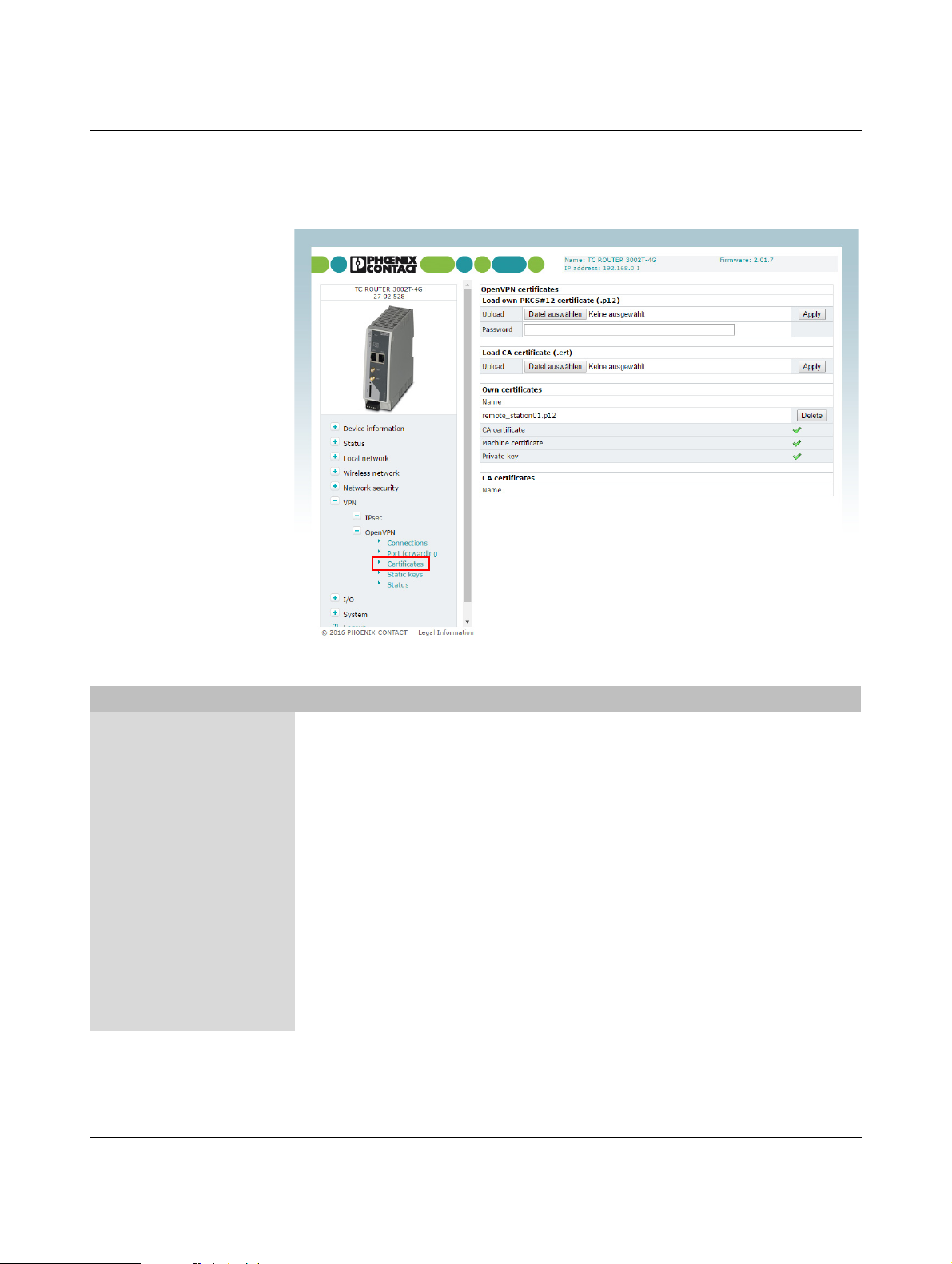
TC ROUTER ... 3G/4G
3.8.5 OpenVPN certificates (certificate upload)
A certificate that has been loaded on the router is used to authenticate the router at the peer.
The certificate acts as an ID card for the router, which it shows to the relevant peer.
Figure 3-35 VPN, OpenVPN, Certificates
VPN, OpenVPN, Certificates
OpenVPN certificates
Load own PKCS#12
certificate (.p12)
Upload Certificate that you have received from your provider. The file
must be in PKCS#12 format. Click on the “Browse” button to
select the certificate to be imported.
Under “VPN, OpenVPN, Connections, Tunnel, Edit“,
Local Certificate, one of these certificates can be assigned
to each VPN connection.
Password Password used to protect the private key of the PKCS#12 file.
The password is assigned when the key is exported.
Load CA certificate (.crt) Upload The CA certificate must be in crt format. Click on the “Browse”
button to select the certificate to be imported.
Under “VPN, OpenVPN, Connections, Tunnel, Edit“,
Local Certificate, one of these certificates can be assigned
to each VPN connection.
68 / 146
PHOENIX CONTACT 107025_en_01

VPN, OpenVPN, Certificates [...]
Own certificates Name Overview of the imported PKCS#12 certificates
CA certificates Name Overview of the imported CA certificates
3.8.6 Static keys (pre-shared secret key authentication)
Static key authentication is based on a symmetrical encryption method where the communication partners first exchange a shared key via a secure channel. All tunnel network traffic
is then encrypted using this key. Network traffic can then be decoded by anyone who has
this key.
Configuration via web-based management
Click on “Delete” to delete a certificate.
The green ticks indicate whether the PKCS#12 file contains a
CA certificate, a machine certificate or a private key.
Click on “Delete” to delete a certificate.
Figure 3-36 VPN, OpenVPN, Static keys
VPN, OpenVPN, Static keys
Open VPN static keys Generate static key Generates a key for the OpenVPN connection. You can store
this key locally on the computer.
Load static key Loads the key on the mobile router.
Static keys Keys stored in the router
107025_en_01 PHOENIX CONTACT 69 / 146

TC ROUTER ... 3G/4G
3.8.7 OpenVPN status (status of the VPN connection)
Figure 3-37 VPN, OpenVPN, Status
VPN, OpenVPN, Status
Open VPN status Active OpenVPN
connections
Status of the active VPN connection
70 / 146
PHOENIX CONTACT 107025_en_01

Configuration via web-based management
3.9 I/O
The router has two integrated digital switching inputs and one integrated digital switching
output for alarms and switching.
3.9.1 Inputs (input configuration)
The inputs can be used to send alarms by SMS or e-mail. Each input can be configured individually. Please note that inputs that are used to start a VPN connection, for example, cannot also be used to send alarms.
Figure 3-38 I/O, Inputs
107025_en_01 PHOENIX CONTACT 71 / 146

TC ROUTER ... 3G/4G
I/O, Inputs
Inputs High If a message should be sent at a “High” input level, activate
“High”. Click on “Apply” for acceptance. Choose whether you
want to be alerted by SMS or e-mail.
Click on “Edit”.
Enter the following for an SMS message:
– Recipient from the phonebook
– Message text
Enter the following for an e-mail alert:
–To: recipient
– Cc: recipient of a copy
–Subject
– Message text
Low If a message should be sent at a “Low” input level, activate
“Low”. Click on “Apply” and choose whether you want to be
alerted by SMS or e-mail.
Click on “Edit”.
Enter the following for an SMS message:
– Recipient from the phonebook
– Message text
Enter the following for an e-mail alert:
–To: recipient
– Cc: recipient of a copy
–Subject
– Message text
72 / 146
PHOENIX CONTACT 107025_en_01

Configuration via web-based management
3.9.2 Outputs (output configuration)
The outputs can be switched remotely or, alternatively, provide information about the status
of the router. Each output can be configured individually.
Figure 3-39 I/O, Outputs
I/O, Outputs
Outputs – Manual: manual switching of the output via the web-
based Management
– Remote controlled: remote switching via SMS or socket
server. Automatic reset of the output can be used as an
option. To do this, activate “Autoreset” and specify the du-
ration in minutes.
– Radio network: the output is switched if the router is
logged in to a mobile network.
– Packet service: the output is switched if the router has
established a packet data connection and received a val-
id IP address from the provider.
– VPN service: the output is switched if the router has
established a VPN connection.
– Incoming call: the output is switched if the router is
called by a phone number listed in the phonebook.
– Connection lost: the output is switched if the router con-
nection check does not reach the configured reference
address.
Autoreset Duration in minutes until the output is reset automatically
107025_en_01 PHOENIX CONTACT 73 / 146

TC ROUTER ... 3G/4G
3.9.3 Phonebook
Enter phone numbers here:
– For the recipients of alarm SMS messages
– For those authorized to switch the outputs
Figure 3-40 I/O, Phonebook
74 / 146
PHOENIX CONTACT 107025_en_01

Configuration via web-based management
3.9.4 Socket server
The router has a socket server, which can accept operating commands via the Ethernet interface. These commands must be sent in XML format.
A client from the local network initiates basic communication. To do this, a TCP connection
is established to the set server port. The socket server responds to the client's requests. It
then terminates the TCP connection. A TCP connection is established again for another request. Only one request is permitted per connection.
Figure 3-41 I/O, Socket server
I/O, Socket server
Socket configuration Socket server – Disabled: operation via Ethernet interface not possible
– Enabled: operation via Ethernet interface possible
Server port (default
1432)
Socket server port (default: 1432)
Please note that port 80 cannot be used for the socket server.
To use the router, a TCP socket connection must be established to the configured port. The data format must conform to
XML Version 1.0.
XML newline char Character which creates a line break in the XML file
– LF: line feed, line break after 0x0A (hex)
– CR: carriage return, line break after 0x0D (hex)
– CR+LF: line break after carriage return, followed by a line
feed
107025_en_01 PHOENIX CONTACT 75 / 146
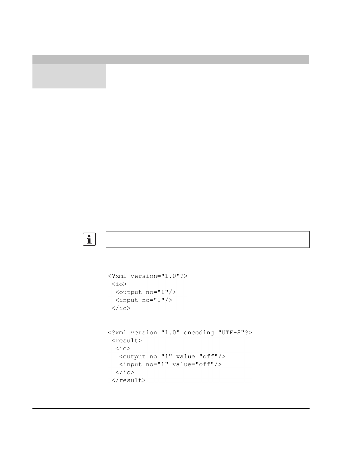
TC ROUTER ... 3G/4G
I/O, Socket server
XML Boolean values Format in which requests are answered via XML
– Verbose: response in words, e.g., on/off
– Numeric: short numerical response, e.g., 1/0
Every XML file generally begins with the header <?xml version="1.0"?> or
<?xml version="1.0" encoding="UTF-8"?> followed by the basic entry.
Basic entries
<io> ........... </io> I/O system
<info> ........... </info> Request general device information
<cmgs> ........... </cmgs> Send SMS messages
<cmgr> ........... </cmgr> Receive SMS messages
<cmga> ........... </cmga> Confirm receipt of SMS
<email> ........... </email> Send e-mails
I/O system
Using the XML socket server, you can:
– query outputs and inputs
– switch outputs
The outputs used must have been previously configured to “Remote controlled”. Depending
on the setting of “XML Boolean values”, on/off or 0/1 can be output as “value”.
Make sure that the XML data does not contain any line breaks.
Query outputs and inputs
Request state of output 1
Request state of input 1
Response from the router (shown with line break):
State output 1
State input 1
76 / 146
PHOENIX CONTACT 107025_en_01

Configuration via web-based management
Switch outputs
Switch output 1
Response from the router (shown with line break):
Output 1 switched
Switch on data connection
First, set the following in the web-based Management:
• Switch on the data connection under "Packet data setup" (enabled see Page 36).
• Under "Event", select the option "Initiate on XML".
⇒ You can now switch on the data connection of the router through XML.
Switch on data connection
Response from the router (shown with line break):
Connection on
107025_en_01 PHOENIX CONTACT 77 / 146

TC ROUTER ... 3G/4G
Request general device information
You can read status information from the device:
Request device data
Data for the wireless connection (mobile devices only)
Request data for the Internet connection
Logical states at the connections
Response from the router (shown with line break):
78 / 146
PHOENIX CONTACT 107025_en_01

Configuration via web-based management
To read just one single value, you can use the “Select” attribute to select it. Here is a request
for the RSSI value as an example:
Send SMS messages
Send XML data with the following structure to the device IP address via Ethernet:
For this purpose, make sure that the XML data does not contain any line breaks. The text
must be UTF-8-coded.
ASCII characters 34
dec
dec
dec
, and 62
dec
must be entered as &quo t; &apo s;
dec
, 38
, 39
, 60
& < and >.
If the XML data was received correctly, the device responds with the transmission status:
Receive SMS messages
To receive SMS messages via Ethernet, enter the following:
Response from the router (shown with line break):
The response means that an SMS message has not been received yet. The following error
codes are possible:
1 Empty = no SMS message received
2Busy = try again later
3 System error = communication problem with the radio engine
107025_en_01 PHOENIX CONTACT 79 / 146

TC ROUTER ... 3G/4G
If the router has received an SMS message and if it is available, then the message is output:
Confirm receipt of SMS
Successful receipt of the SMS via Ethernet must be confirmed with the following command:
Response from the router (shown with line break):
This SMS message is then marked as read on the router.
Send e-mails
Send XML data with the following structure to the device IP address via Ethernet:
80 / 146
Response from the router (shown with line break):
Response from the router in the event of an error:
PHOENIX CONTACT 107025_en_01

Configuration via web-based management
Start and stop VPN connections
To start and stop IPsec and OpenVPN connections, send XML data with the following structure to the device IP address via Ethernet:
Start IPsec connection 2
Start OpenVPN connection
Response from the router (shown with line break):
107025_en_01 PHOENIX CONTACT 81 / 146

TC ROUTER ... 3G/4G
3.10 System
3.10.1 System configuration
Set the basic options for web-based management and router logging here. The router can
store log files on an external log server via UDP.
System, system configuration
System configuration
Web configuration Server port The web-based management of the router can be accessed
82 / 146
PHOENIX CONTACT 107025_en_01
Figure 3-42 System, System configuration
via this port using HTTP (default: 80).
Web server access Choose how web-based management can be accessed:
– Using the HTTP and HTTPS protocol (default)
–Using HTTP only
–Using HTTPS only
For security reasons, external access via the mobile network
is only possible using the HTTPS protocol.
HTTPS port The web-based management of the router can be accessed
via this port using HTTPS (default: 443).
Certificate validity Specify the validity period of the certificate for HTTPS access
to web-based management here (default: 1825 days).

System, system configuration
Log configuration Remote UDP logging – Disabled: no external logging
Configuration via web-based management
HTTPS certificate To create a new certificate for HTTPS access to web-based
management, click on “Renew certificate”. This certificate is
valid for the period set under “Certificate validity”.
– Enabled: logging on external server activated.
Server IP address IP address of the log server
Server port Log server port (default: 514)
Non volatile log – Disabled: temporary logging
– Enabled: permanent logging on microSD card
Load configuration – Disabled: configuration is not loaded automatically when
the router is started
– SD card: configuration is loaded automatically when the
router is started. The configuration is loaded from a
microSD card.
Configuration unlock – Once: a configuration is loaded once next time the router
is started. The configuration is loaded from a microSD
card.
– Always: a configuration is loaded every time the router is
started. The configuration is loaded from a microSD card.
– By input 1: a configuration is loaded from a microSD
card, controlled via switching input 1
– By input 2: a configuration is loaded from a microSD
card, controlled via switching input 2
Reset button – Web access reset: the IP address and access data for
the administrator are reset to the default settings via the
reset button. The configuration is retained.
– Factory reset: the device is completely reset to the deliv-
ery state via the reset button. The configuration will be de-
leted.
Connect LED function – Internet connectivity: packet data connection via
mobile network active
– VPN connectivity: VPN connection active (IPsec or
OpenVPN)
107025_en_01 PHOENIX CONTACT 83 / 146

TC ROUTER ... 3G/4G
System, system configuration
Energy saving mode – None: no energy-saving mode
– Initiate on input 1: energy-saving mode, activated via
switching input 1.
– Initiate on input 2: energy-saving mode, activated via
switching input 2.
Radio engine: energy-saving mode deactivates the radio engine. If energy-saving mode is active, mobile communication
is no longer possible.
Ethernet LAN1/2: energy-saving mode deactivates Ethernet
interface LAN 1/2. If energy-saving mode is active, communication is no longer possible via this interface.
84 / 146
PHOENIX CONTACT 107025_en_01

3.10.2 User (password change)
Configuration via web-based management
Figure 3-43 System, User
System, user
User setup Admin Unrestricted access to all areas
– Old password
– New password
– Retype new password
User Restricted access (read-only)
Default: public
– Old password
– New password
– Retype new password
107025_en_01 PHOENIX CONTACT 85 / 146

TC ROUTER ... 3G/4G
3.10.3 Log file
The router log file can be used to diagnose various events and operating states. The log file
is a form of circulating storage where the oldest entries are overwritten first.
Figure 3-44 System, Log file
System, log file
Log file Clear Delete all entries in the log file
View View log file in the browser window
Save Save log file as text file on local computer
86 / 146
PHOENIX CONTACT 107025_en_01

Configuration via web-based management
3.10.4 SNMP configuration (router monitoring)
The router supports the reading of information via SNMP (Simple Network Management
Protocol). SNMP is a network protocol that can be used to monitor and control network
elements from a central station. The protocol controls communication between the monitored devices and the central station.
Figure 3-45 Local network, SNMP configuration
Local network, SNMP configuration
SNMP configuration
System information
Name of device Name for management purposes, can be freely assigned
Description Description of the router
Physical location Designation for the installation location, can be freely
Contact Contact person responsible for the router
SNMPv1/v2 community
Enable SNMPv1/2
access
Read only Password for read access via SNMP
Read and write Password for read and write access via SNMP
Enable SNMPv3
access
assigned
– Yes: SNMP Version 1 and Version 2 are used.
– No: the service is deactivated (default).
– Yes: SNMP Version 3 is used.
– No: the service is deactivated (default).
107025_en_01 PHOENIX CONTACT 87 / 146

TC ROUTER ... 3G/4G
Local network, SNMP configuration [...]
Trap configuration In certain cases, the router can send SNMP traps. The traps
Tra p m a n a g e r I P
address
Port Port to which the trap will be sent
Target community Name of the SNMP community to which the trap is assigned.
Sending traps – Disabled: it is not possible to send traps to the IP address
3.10.5 E-mail configuration
To send alarms by e-mail, the e-mail server via which these alerts are sent can be configured here. The e-mail server must support the SMTP protocol.
correspond to SNMPv1. They are part of the standard MIB.
IP address to which the trap will be sent
of the trap manager.
– Enabled: the sending of traps to the IP address of the trap
manager is activated.
88 / 146
Figure 3-46 System, E-mail configuration
PHOENIX CONTACT 107025_en_01

Configuration via web-based management
System, E-mail configuration
E-mail configuration SMTP server Host name or IP address of the e-mail server
– Local: the IP packets for the SMTP server are sent from
the local network interface with the IP address of the local
interface (LAN).
– Wireless network: the IP packets for the SMTP server
are sent from the mobile network interface with the IP
address assigned by the provider.
Server port E-mail server port (default: 25)
Tra n s p o r t l a y e r
security
– None: unencrypted connection to e-mail server
– STARTTLS: STARTTLS-encrypted connection to the
e-mail server
– SSL/TLS: SSL/TLS-encrypted connection to the e-mail
server
Authentication – No authentication: no authentication required.
– Plain password: authentication with user name and
password. User name and password are transmitted in
unencrypted form.
– Encrypted password: authentication with user name
and password. User name and password are transmitted
in encrypted form.
User name User name for login to the e-mail server
Password Corresponding password for login to the e-mail server
From E-mail address of the sender
107025_en_01 PHOENIX CONTACT 89 / 146

TC ROUTER ... 3G/4G
3.10.6 Configuration up-/download
You can save the active configuration to a file and load prepared configurations via WBM.
Figure 3-47 System, Configuration up-/download
System, Configuration up-/download
Configuration
Download To save the active configuration to a microSD card, select the
up-/download
Upload To load a configuration from the microSD card, select the “SD
Reset to factory
defaults
“SD card” option under “Download”.
Click on “Save” to save the active configuration locally to a file.
Enable the “XML format” option to save the router configuration as an editable XML structure.
card” option under “Upload”.
Import a saved configuration. Click on the “Browse” button to
select the configuration that is to be imported. Click on “Apply”
to load the selected configuration (cfg format or XML format).
Click on “Apply” to reset the router to the default state upon delivery. This will reset all settings, including IP settings.
Imported certificates remain unaltered.
90 / 146
PHOENIX CONTACT 107025_en_01

3.10.7 Date/time
Configuration via web-based management
Figure 3-48 System, Date/time
System, date/time
Date/time System time You can set the time manually if no NTP server (time server)
has been set up or the NTP server cannot be reached.
Time synchronisation – Enabled: the router synchronizes the time and date with
a time server. Initial time synchronization can take up to
15 minutes. During this time, the router continuously com-
pares the time data of the external time server and that of
its own clock. The time is therefore adjusted as accurately
as possible. Only then can the router act as the NTP serv-
er for the devices connected to the LAN interface. The
router then provides the system time.
107025_en_01 PHOENIX CONTACT 91 / 146

TC ROUTER ... 3G/4G
System, date/time [...]
NTP server NTP = Network Time Protocol
The router can act as the NTP server for the devices connected to the LAN interface. In this case, the devices should
be configured so that the local address of the router is specified as the NTP server address. For the router to act as the
NTP server, it must obtain the current date and time from an
NTP server (time server). In order to do this you must specify
the address of a time server. In addition, NTP synchronization
must be set to “Enabled”.
A green tick is displayed following successful time synchronization with the time server.
– Local: the specified NTP server can be accessed with the
IP address of the local interface (LAN). Activate this op-
tion if the NTP server can be accessed in the local LAN or
via a VPN tunnel.
– Wireless network: activate this option if the NTP server
is on the Internet (default).
Time zone Select the time zone.
Daylight saving time – Enabled: daylight savings is taken into account.
– Disabled: daylight savings is not taken into account.
Time server for local
Time server for the local network
network
92 / 146
PHOENIX CONTACT 107025_en_01

3.10.8 Reboot (router restart)
Do not trigger a reboot while data transmission
is active.
Configuration via web-based management
Figure 3-49 System, Reboot
System, reboot
Reboot Reboot NOW! Restarting the router
Any active data transmissions will be aborted.
Daily reboot Define the day of the week on which the router will be restarted
at the specified time.
Following a reboot, it is necessary to log in to the mobile network again. The provider resets the data link and calculates
charges. Regular rebooting provides protection against the
provider aborting and re-establishing the connection at an unforeseeable point in time.
Time Time specified in Hours:Minutes
Event Choose the digital input with the “High” signal which will be
used to restart the router if required.
Make sure that following a restart the signal is “Low” again.
This ensures that the router starts up normally.
107025_en_01 PHOENIX CONTACT 93 / 146

TC ROUTER ... 3G/4G
Do not start the router manually.
Do not interrupt the power supply during the update process.
3.10.9 Firmware update
Figure 3-50 System, Firmware update
System, Firmware update
Device firmware update Updates ensure that you can benefit from function extensions
and product updates.
Updates can be downloaded at: phoenixcontact.net/products.
Install firmware update:
• Click on “Select file” and select the update file with the
extension *.fw. To ensure that the active configuration is
retained following the update, select the “Keep configura-
tion” option.
• Click on “Install firmware”.
• The ERR LED and CON LED flash alternately during the
update. Wait until the update is completed and the router
restarts automatically.
Package update If necessary you can also just update individual router func-
tions.
94 / 146
PHOENIX CONTACT 107025_en_01

4 Creating X.509 certificates
Certificates are required for a secure VPN connection. Certificates can be acquired from
certification bodies or you can create them using the appropriate software. In this example,
X.509 certificates are created using Version 0.9.3 of the XCA program.
Creating X.509 certificates
The XCA program can be downloaded at http://xca.sourceforge.net
4.1 Installation
• Start the setup file. Follow the instructions in the setup program.
4.2 Creating a new database
• Start the XCA program.
• Create a new database via “File, New Database”.
.
Figure 4-1 Creating a new database
107025_en_01 PHOENIX CONTACT 95 / 146

TC ROUTER ... 3G/4G
• Assign a password to encrypt the database.
Figure 4-2 Assigning a password
4.3 Creating a CA certificate
First of all, create a Certification Authority (CA) certificate. This root certificate acts as an entity that certifies and authenticates the signing of all certificates that are derived from it and
thus guarantees the authenticity of these certificates.
• Switch to the “Certificates” tab and create a new certificate.
In the program window shown, there is already a preset self-signed certificate with the signature algorithm SHA-1.
96 / 146
Figure 4-3 Creating a new CA certificate
PHOENIX CONTACT 107025_en_01

Creating X.509 certificates
• On the “Subject” tab, enter the information about the owner of the root certificate.
Figure 4-4 Entering information about the owner
• Create a key for this certificate. The default name, key type, and key size can be retained.
Figure 4-5 Creating a key
107025_en_01 PHOENIX CONTACT 97 / 146

TC ROUTER ... 3G/4G
The period of validity of the certificate is specified on the “Extensions” tab. The root certificate must be valid for longer than the machine certificates that are to be created later. In this
example, the validity is set to ten years.
• Set the certificate type to “Certification Authority”.
• Activate all the options as shown in Figure 4-6.
Figure 4-6 Setting the validity and type for the CA certificate
• Click OK.
The certificate is created. A new root certificate from which further machine certificates can
be derived now appears in the overview.
Figure 4-7 CA certificate created
98 / 146
PHOENIX CONTACT 107025_en_01

Creating X.509 certificates
4.4 Creating templates
By using templates, you can create machine certificates quickly and easily.
• Switch to the “Templates” tab and create a new template for a terminal certificate.
• When prompted about template values, select “Nothing”.
Figure 4-8 Creating a new template
• Default settings for the certificates to be created later can be made on the “Subject” tab.
The name must be specified in the relevant certificates. The text specified in the angle
brackets is a placeholder which is replaced when the template is applied.
Figure 4-9 Creating a template, entering information about the owner
107025_en_01 PHOENIX CONTACT 99 / 146

TC ROUTER ... 3G/4G
• On the “Extensions” tab, set the certificate type to “End Entity” as the template should
be valid for machine certificates.
• The validity of the certificates to be created is 365 days in this example. Once the end
date has elapsed, the certificates can no longer be used.
Figure 4-10 Creating a template, entering the validity and type of certificate
• Click OK.
The template is created. You can now use the template as a basis to create certificates
signed by the root certificate.
100 / 146
PHOENIX CONTACT 107025_en_01
 Loading...