

Page 1

Radioline Wireless transmission system for
serial interfaces and I/O signals
User manual
Page 2

User manual
Radioline Wireless transmission system for
serial interfaces and I/O signals
2017-01-10
Designation:
Revision:
This user manual is valid for:
Wireless modules: Order No.
RAD-2400-IFS 2901541
RAD-868-IFS 2904909
RAD-2400-IFS-JP 2702863
I/O extension modules:
RAD-AI4-IFS 2901537
RAD-PT100-4-IFS 2904035
RAD-AO4-IFS 2901538
RAD-DI4-IFS 2901535
UM EN RAD-...-IFS
02
RAD-DI8-IFS 2901539
RAD-DOR4-IFS 2901536
RAD-DO8-IFS 2902811
RAD-DAIO6-IFS 2901533
PHOENIX CONTACT 105542_en_02
Page 3

Please observe the following notes
User group of this manual
The use of products described in this manual is oriented exclusively to qualified electricians
or persons instructed by them, who are familiar with applicable standards and other
regulations regarding electrical engineering and, in particular, the relevant safety concepts.
Explanation of symbols used and signal words
This is the safety alert symbol. It is used to alert you to potential personal injury
hazards. Obey all safety measures that follow this symbol to avoid possible
injury or death.
There are three different categories of personal injury that are indicated with a
signal word.
DANGER This indicates a hazardous situation which, if not avoided, will
result in death or serious injury.
WARNING This indicates a hazardous situation which, if not avoided, could
result in death or serious injury.
CAUTION This indicates a hazardous situation which, if not avoided, could
result in minor or moderate injury.
This symbol together with the signal word NOTE and the accompanying text
alert the reader to a situation which may cause damage or malfunction to the
device, hardware/software, or surrounding property.
This symbol and the accompanying text provide the reader with additional
information or refer to detailed sources of information.
How to contact us
Internet Up-to-date information on Phoenix Contact products and our Terms and Conditions can be
found on the Internet at:
phoenixcontact.com
Make sure you always use the latest documentation.
It can be downloaded at:
phoenixcontact.net/products
Subsidiaries If there are any problems that cannot be solved using the documentation, please contact
your Phoenix Contact subsidiary.
Subsidiary contact information is available at phoenixcontact.com
Published by PHOENIX CONTACT GmbH & Co. KG
Flachsmarktstraße 8
32825 Blomberg
GERMANY
Should you have any suggestions or recommendations for improvement of the contents and
layout of our manuals, please send your comments to:
tecdoc@phoenixcontact.com
.
PHOENIX CONTACT
Page 4

Please observe the following notes
General terms and conditions of use for technical documentation
Phoenix Contact reserves the right to alter, correct, and/or improve the technical
documentation and the products described in the technical documentation at its own
discretion and without giving prior notice, insofar as this is reasonable for the user. The
same applies to any technical changes that serve the purpose of technical progress.
The receipt of technical documentation (in particular user documentation) does not
constitute any further duty on the part of Phoenix Contact to furnish information on
modifications to products and/or technical documentation. You are responsible to verify the
suitability and intended use of the products in your specific application, in particular with
regard to observing the applicable standards and regulations. All information made
available in the technical data is supplied without any accompanying guarantee, whether
expressly mentioned, implied or tacitly assumed.
In general, the provisions of the current standard Terms and Conditions of Phoenix Contact
apply exclusively, in particular as concerns any warranty liability.
This manual, including all illustrations contained herein, is copyright protected. Any
changes to the contents or the publication of extracts of this document is prohibited.
Phoenix Contact reserves the right to register its own intellectual property rights for the
product identifications of Phoenix Contact products th at are u sed here. R egistr ati on of su ch
intellectual property rights by third parties is prohibited.
Other product identifications may be afforded legal protection, even where they may not be
indicated as such.
PHOENIX CONTACT
Page 5

Table of contents
1 Technical data for the wireless modules ....................................................................................9
2 For your safety .........................................................................................................................17
2.1 Intended use........................................................................................................17
2.2 Installation notes..................................................................................................18
2.3 Installation in Zone 2............................................................................................19
2.4 Notes for individual I/O extension modules..........................................................21
2.5 UL notes (RAD-2400-IFS only)............................................................................ 21
2.6 FCC and Industry Canada (RAD-2400-IFS only).................................................22
3 Short description ......................................................................................................................23
3.1 Wireless modules................................................................................................23
3.2 Firmware versions ...............................................................................................24
3.3 I/O extension modules.........................................................................................25
4 Installation ................................................................................................................................27
4.1 Wireless module structure...................................................................................27
4.2 Basic circuit diagram ...........................................................................................28
4.3 Mounting and removal.........................................................................................28
4.4 Connecting cables...............................................................................................30
4.5 Connecting the power supply ..............................................................................31
4.6 Serial interfaces...................................................................................................32
4.7 Connecting the antenna ......................................................................................35
5 Configuration and startup .........................................................................................................37
5.1 Default settings of the wireless module ...............................................................37
5.2 Operating mode of the wireless module ..............................................................39
5.3 Setting the address of the wireless module using the thumbwheel...................... 42
5.4 Configuration via CONFSTICK............................................................................42
5.5 Copying device settings via a memory stick ........................................................44
5.6 Configuration via PSI-CONF software.................................................................45
5.7 Diagnostics on the wireless module .................................................................... 51
5.8 Diagnostics via PSI-CONF software....................................................................56
5.9 Starting up I/O extension modules.......................................................................59
5.10 Startup time of the wireless station......................................................................61
6 Serial data mode ......................................................................................................................63
6.1 Frame-based data transmission..........................................................................65
105542_en_02 PHOENIX CONTACT 5
Page 6

RAD-...-IFS
7 PLC/Modbus RTU mode ..........................................................................................................67
7.1 Configuration via PSI-CONF software.................................................................67
7.2 Addressing I/O extension modules......................................................................68
7.3 Watchdog............................................................................................................69
7.4 Modbus function codes .......................................................................................70
7.5 Module type and error code registers for I/O extension modules.........................71
7.6 Modbus memory map..........................................................................................72
7.7 Error codes and formats for analog input and output values................................87
8 Description of I/O extension modules ......................................................................................89
8.1 RAD-AI4-IFS - analog extension module with four inputs ....................................89
8.2 RAD-PT100-4-IFS - extension module with four temperature inputs ...................93
8.3 RAD-AO4-IFS - analog extension module with four outputs.............................. 100
8.4 RAD-DI4-IFS - digital extension module with four inputs ...................................104
8.5 RAD-DI8-IFS - digital extension module with eight inputs..................................108
8.6 RAD-DOR4-IFS - digital extension module with four outputs.............................113
8.7 RAD-DO8-IFS - digital extension module with eight outputs..............................117
8.8 RAD-DAIO6-IFS - analog/digital extension module with six channels ............... 122
9 Planning wireless systems .....................................................................................................127
9.1 Delay time .........................................................................................................127
9.2 Pulse transmission ............................................................................................129
9.3 Trusted Wireless 2.0..........................................................................................129
9.4 RF bands...........................................................................................................133
9.5 Planning wireless paths.....................................................................................134
9.6 Practical test......................................................................................................134
9.7 Selecting antenna cables and antennas............................................................135
9.8 Installing antennas.............................................................................................136
9.9 Level and attenuation of wireless modules and accessories .............................139
9.10 Free space path loss .........................................................................................141
9.11 Propagation of radio waves...............................................................................143
9.12 Fresnel zone......................................................................................................146
9.13 Range................................................................................................................148
9.14 Equivalent isotropically radiated power (EIRP)..................................................149
9.15 System calculation in free space .......................................................................150
9.16 Practical examples ............................................................................................151
6
PHOENIX CONTACT 105542_en_02
Page 7

Table of contents
10 Detecting and removing errors ...............................................................................................153
10.1 Loopback test during serial data transmission...................................................159
A Technical appendix.................................................................................................................161
A 1 Typical combinations of antennas and adapter cables ...................................... 161
A 2 Control box for wireless systems.......................................................................175
A 3 PROFIBUS connections....................................................................................176
A 4 Configuration.....................................................................................................178
B Appendixes.............................................................................................................................189
B 1 List of figures .....................................................................................................189
B 2 List of tables ......................................................................................................193
B 3 Index..................................................................................................................195
105542_en_02 PHOENIX CONTACT 7
Page 8

RAD-...-IFS
8
PHOENIX CONTACT 105542_en_02
Page 9

Technical data for the wireless modules
1 Technical data for the wireless modules
Description Ty p e Order No. Pcs./Pkt.
2400 MHz wireless transceiver with RS-232, RS-485 2-wire interface, can
be extended with I/O extension modules, with screw connection, antenna
connection: RSMA (female), incl. DIN rail connector, without antenna
868 MHz wireless transceiver with RS-232, RS-485 2-wire interface, can
be extended with I/O extension modules, with screw connection, antenna
connection: RSMA (female), incl. DIN rail connector, without antenna
2400 MHz wireless transceiver for operation in Japan, with RS-232,
RS-485 2-wire interface, can be extended with I/O extension modules, with
screw connection, antenna connection: RSMA (female), incl. DIN rail connector, without antenna (no ATEX, IECEx or UL approval)
Accessories
RS-485 front module Ty p e Order No. Pcs./Pkt.
Multipoint multiplexer for RS-485 bus system, can be extended with I/O extension modules. Can be used as Modbus/RTU bus coupler or combined
with Radioline wireless system, screw connection. Up to 99 stations, incl.
DIN rail connector
Extension modules Ty p e Order No. Pcs./Pkt.
Analog I/O extension module with 4 analog current inputs
(0/4 mA ... 20 mA), with screw connection, incl. DIN rail connector
Temperature I/O extension module with 4 Pt 100 inputs
(-50°C … +250°C), with screw connection, incl. DIN rail connector
Analog I/O extension module with 4 analog current/voltage outputs
(0/4 mA ... 20 mA, 0 V ... 10 V), with screw connection, incl. DIN rail connector
Digital I/O extension module with 4 digital inputs (0 V ... 250 V AC/DC),
with screw connection, incl. DIN rail connector
Digital I/O extension module with 8 digital inputs (0 V ... 30.5 V DC) or
2 pulse inputs (0 Hz ... 100 Hz), with screw connection, incl. DIN rail connector
Digital I/O extension module with 4 digital relay outputs (6 A,
250 V AC/24 V DC), with screw connection, incl. DIN rail connector
Digital I/O extension module with 8 digital transistor outputs
(30.5 V DC/200 mA), with screw connection, incl. DIN rail connector
Analog/digital I/O extension module with 2 digital inputs/outputs
(0 V ... 250 V AC/DC) and 1 analog input (0/4 mA ... 20 mA) and output
(0/4 mA ... 20 mA, 0 V ... 10 V), with screw connection, incl. DIN rail connector
RAD-2400-IFS 2901541 1
RAD-868-IFS 2904909 1
RAD-2400-IFS-JP 2702863 1
RAD-RS485-IFS 2702184 1
RAD-AI4-IFS 2901537 1
RAD-PT100-4-IFS 2904035 1
RAD-AO4-IFS 2901538 1
RAD-DI4-IFS 2901535 1
RAD-DI8-IFS 2901539 1
RAD-DOR4-IFS 2901536 1
RAD-DO8-IFS 2902811 1
RAD-DAIO6-IFS 2901533 1
105542_en_02 PHOENIX CONTACT 9
Page 10

RAD-...-IFS
Mounting and configuration Ty p e Order No. Pcs./Pkt.
DIN rail connector for DIN rail power supply, gold-plated contacts, for
DIN rail mounting, 5-pos.
Shield connection clamp for applying the shield on busbars SKS 8-SNS35 3062786 10
Memory stick for saving individual configuration data for the Radioline wire-
less module
USB data cable (USB-A to IFS connector) for communicating between PCs
and PHOENIX CONTACT devices with an IFS data port, e.g.,
RAD-2400-IFS. Energy supply for diagnostics and configuration via the
USB port of the PC. Cable length: 2 m
Vulcanizing sealing tape for external protection of adapters, cable connections, etc. against the effects of weather, roll length: 3 m
ME 17,5 TBUS 1,5/ 5-ST-3,81 GN 2709561 10
RAD-MEMORY 2902828 1
RAD-CABLE-USB 2903447 1
RAD-TAPE-SV-19-3 2903182 1
CONFSTICKS 2.4 GHz Ty p e Order No. Pcs./Pkt.
CONFSTICK for easy and safe network addressing for the 2.4 GHz Radioline wireless module (RAD-2400-IFS), unique network ID, RF band 3
CONFSTICK for easy and safe network addressing for the 2.4 GHz Radioline wireless module (RAD-2400-IFS), unique network ID, RF band 5
CONFSTICK for easy and safe network addressing for the 2.4 GHz Radioline wireless module (RAD-2400-IFS), unique network ID, RF band 7
RAD-CONF-RF3 2902814 1
RAD-CONF-RF5 2902815 1
RAD-CONF-RF7 2902816 1
CONFSTICK 868 MHz Ty p e Order No. Pcs./Pkt.
CONFSTICK for easy and safe network addressing for the 868 MHz
Radioline wireless module (RAD-868-IFS), unique network ID, RF band 1
RAD-868-CONF-RF1 2702197 1
2.4 GHz antennas Ty p e Order No. Pcs./Pkt.
Omnidirectional antenna, 2.4 GHz, 2 dBi, linear vertical, 1.5 m cable,
RSMA (male), IP65, 50 Ω impedance
Omnidirectional antenna with protection against vandalism, 2.4 GHz,
3 dBi gain, IP55 degree of protection, 1.5 m cable length,
RSMA (male) connection, h/v 360°/85° opening angle
Appropriate mounting material is available for wall mounting.
Omnidirectional antenna, 2.4 GHz, 6 dBi, linear vertical, h/v 360°/30°
opening angle, N (female), IP55, incl. mounting bracket and mast clips for
45 mm ... 100 mm diameter, stainless steel, ATEX/IECEx approval
Omnidirectional antenna, 2.4 GHz, 6 dBi, linear vertical, h/v 360°/20°
opening angle, N (female), IP65, seawater-resistant
Omnidirectional antenna, 2.4 GHz, 9 dBi, linear vertical, N (female), IP65,
50 Ω impedance
Directional antenna , 2.4/5 GHz, 9 dBi, linear vertical, N (female), IP67, incl.
mounting bracket and mast clips for 25 mm ... 85 mm diameter, stainless
steel, ATEX/IECEx approval
Parabolic antenna, IP65 degree of protection, 19 dBi gain, linear vertical,
N (female) connection, 50 Ω impedance, h/v 17°/11° opening angle
RAD-ISM-2400-ANT-OMNI-2-1-RSMA 2701362 1
RAD-ISM-2400-ANT-VAN-3-0-RSMA 2701358 1
RAD-ISM-2400-ANT-OMNI-6-0 2885919 1
RAD-2400-ANT-OMNI-6-0-SW 2903219 1
RAD-ISM-2400-ANT-OMNI-9-0 2867623 1
ANT-DIR-2459-01 2701186 1
RAD-ISM-2400-ANT-PAR-19-0 2867885 1
10
PHOENIX CONTACT 105542_en_02
Page 11

Technical data for the wireless modules
868 MHz antennas Ty p e Order No. Pcs./Pkt.
Omnidirectional antenna, 868 MHz, 4 dBi, linear vertical, N (female),
h/v 360°/30° opening angle, IP67, seawater-resistant, incl. mounting
bracket and mast clips for 30 mm ... 45 mm diameter, stainless steel,
ATEX/IECEx approval
Omnidirectional antenna, 868/900 MHz, 2 dBi, linear vertical polarization,
N (female), IP66
Directional antenna, 868 MHz, 3.5 dBi, circular polarized, N (female), IP67,
incl. mounting bracket and mast clips for 25 mm ... 85 mm diameter,
stainless steel, ATEX/IECEx approval
Yagi directional antenna, 868/900 MHz, 8.5 dBi, IP65 degree of protection,
linear vertical polarization, 0.6 m cable length, N (female) connection
Yagi directional antenna, 868/900 MHz, 12.15 dBi, IP65 degree of protection, linear vertical polarization, 0.6 m cable length, N (female) connection
ANT-OMNI-868-01 2702136 1
RAD-900-ANT-OMNI-2-N 2904802 1
ANT-DIR-868-01 2702137 1
RAD-ISM-900-ANT-YAGI-6.5-N 2867814 1
RAD-ISM-900-ANT-YAGI-10-N 5606614 1
Antenna cables and adapters Ty p e Order No. Pcs./Pkt.
Adapter cable as control cabinet feed-through,
N (female) -> RSMA (male), 50 Ω impedance, 0.5 m length
Antenna cable, 0.5 m length, N (male) -> RSMA (male), 50 Ω impedance RAD-PIG-RSMA/N-0.5 2903263 1
Antenna cable, 1 m length, N (male) -> RSMA (male), 50 Ω impedance RAD-PIG-RSMA/N-1 2903264 1
Antenna cable, 2 m length, N (male) -> RSMA (male), 50 Ω impedance RAD-PIG-RSMA/N-2 2903265 1
Antenna cable, 3 m length, N (male) -> RSMA (male), 50 Ω impedance RAD-PIG-RSMA/N-3 2903266 1
Antenna cable, 5 m length, N (male) -> RSMA (male), 50 Ω impedance RAD-PIG-RSMA/N-5 2702140 1
Antenna cable as accessory for leaky wave cable, 0.5 m length,
N (male) -> N (male), attenuation approximately 0.93 dB at 2.4 GHz and
1.6dB at 5GHz
For RAD-2400-IFS: attachment plug with Lambda/4 technology as surge
protection for coaxial signal interfaces. Connection: N connectors
(socket/socket)
For RAD-868-IFS: attachment plug with Lambda/4 technology as surge
protection for coaxial signal interfaces. Connection: N connectors
(socket/socket)
Adapter, N (female) -> N (female) RAD-ADP-N/F-N/F 2867843 1
Adapter, RSMA (male) -> RSMA (female) 90°; insertion loss <0.3 dB at
2.4 GHz
Antenna barrier for installation in Ex Zone 2, separates and transmits
HF signals with intrinsic safety (Ex i) to an antenna in Zone 0, 1 or 2,
0.7 GHz ... 6 GHz frequency range, N (female) -> N (female), ATEX/IECEx
approval
2-way distributor for antenna signals (antenna splitter), N connection
(socket) at the two upper ends and N connection (socket) at the lower end
Antenna cable, 3 m length, N (male) -> N (male), 50 Ω impedance RAD-CAB-EF393- 3M 2867649 1
Antenna cable, 5 m length, N (male) -> N (male), 50 Ω impedance RAD-CAB-EF393- 5M 2867652 1
Antenna cable, 10 m length, N (male) -> N (male), 50 Ω impedance RAD-CAB-EF393-10M 2867665 1
Antenna cable, 15 m length, N (male) -> N (male), 50 Ω impedance RAD-CAB-EF393-15M 2885634 1
RAD-PIG-EF316-N-RSMA 2701402 1
FL LCX PIG-EF142-N-N 2700677 1
CN-LAMBDA/4-5.9-BB 2838490 1
CN-LAMBDA/4-2.2-BB 2800024 1
RAD-ADP-RSMA/M-RSMA/F-90 2904790 1
BAR-ANT-N-N-EX 2702198 1
RAD-SPL-2-N/N 2702293 1
105542_en_02 PHOENIX CONTACT 11
Page 12

RAD-...-IFS
17,5
99
114,5
17,5
99
114,5
Energy supply Ty p e Order No. Pcs./Pkt.
24 V/100 Wp solar system for worldwide use. Consisting of a solar panel,
prewired control cabinet with charge controller, solar batteries, fuses,
surge protection, and mounting material (incl. mast clips).
24 V/200 Wp solar system for worldwide use. Consisting of a solar panel,
prewired control cabinet with charge controller, solar battery, fuses, surge
protection, and mounting material (incl. mast clips).
DIN rail power supply unit, primary-switched, narrow design,
output: 24 V DC/1.5 A
RAD-SOL-SET-24-100 2885472 1
RAD-SOL-SET-24-200 2917722 1
MINI-SYS-PS-100-240AC/24DC/1.5 2866983 1
Control box Ty p e Order No. Pcs./Pkt.
Control box for robust construction of wireless systems for industrial applications, IP65, 25 x 18 x 13 cm, polycarbonate material, gray, drilled, incl.
DIN rail, plugs, and screw connections, without devices
FL RUGGED BOX 2701204 1
Dimensions (nominal sizes in mm)
Dimensions W / H / D 17.5 mm / 99 mm / 114.5 mm
General data
Overvoltage category II
Degree of protection IP20
Pollution degree 2
Housing design PA 6.6 FR, green
Flammability rating UL 94 V0
Supply
Supply voltage range 19.2 V DC ... 30.5 V DC
Maximum current consumption ≤65 mA (at 24 V DC, at 25°C, stand-alone)
Transient surge protection Yes
12
PHOENIX CONTACT 105542_en_02
≤6 A (at 24 V DC, with DIN rail connector at full capacity)
Page 13

Technical data for the wireless modules
System limits RAD-2400-IFS... RAD-868-IFS
Wireless module
Number of supported devices
Number of possible extension modules
Wireless network
I/O data mode
Serial data mode
PLC/Modbus RTU mode
≤250 (addressing via PSI-CONF software)
≤99 (addressing via thumbwheel)
≤32 (per wireless module)
≤99 (I/O extension modules per wireless network, serial interface deactivated)
0 (no I/O extension modules can be used)
≤99 (access to I/O extension modules via Modbus/RTU protocol)
≤99 (per wireless network)
≤32 (per wireless module)
Wireless interface RAD-2400-IFS... RAD-868-IFS
Antenna connection method RSMA (female)
Direction Bidirectional
Frequency 2.4 GHz 868 MHz
Frequency range 2.4002 GHz ... 2.4785 GHz 869.4 MHz ... 869.65 MHz
Number of channel groups 8 14
Number of channels per group 55 Channel distance 1.3 MHz 30 kHz
Data transmission rate (adjustable) 16 kbps
Receiver sensitivity -106.00 dBm (16 kbps)
Transmission power ≤20 dBm (outside of Europe, adjust-
Safety 128-bit data encryption
Operating mode I/O data (default setting, configuration via thumbwheel)
125 kbps
250 kbps
-96.00 dBm (125 kbps)
-93.00 dBm (250 kbps)
able via software)
≤19 dBm (Europe, adjustable via soft-
ware, depends on the data rate)
≤18 dBm (default setting)
Serial data (activation and configuration via PSI-CONF software)
PLC/Modbus RTU mode (activation and configuration via PSI-CONF software)
(depending on the network structure
and data transmission rate)
1.2 kbps
9.6 kbps
19.2 kbps
60 kbps
120 kbps
-122 dBm (1.2 kbps)
-114 dBm (9.6 kbps)
-111 dBm (19.2 kbps)
-104 dBm (60 kbps)
-103 dBm (120 kbps)
≤27 dBm (default setting, adjustable)
RS-232 interface
Connection method COMBICON plug-in screw terminal block
Connection technology 3-wire
Data rate 0.3 kbps ... 115.2 kbps
RS-485 interface
Connection method COMBICON plug-in screw terminal block
Connection technology 2-wire
Data rate 0.3 kbps ... 187.5 kbps
Termination resistor (can be switched on via DIP switches) 390 Ω
105542_en_02 PHOENIX CONTACT 13
150 Ω
390 Ω
Page 14

RAD-...-IFS
Configuration interface
Connection method S-PORT (socket)
RSSI output
Number of outputs 1
Voltage output signal 0 V ... 3 V
RF link relay output
Number of outputs 1
Contact type Changeover contact
Contact material PdRu, gold-plated
Maximum switching voltage 30 V AC/DC / 60 V DC
Maximum switching current 500 mA (30 V AC/DC) / 300 mA (60 V DC)
Electrical service life 5 x 10⁵ switching cycles with 0.5 A at 30 V DC
Connection data
Connection method Screw connection
Conductor cross section solid 0.2 mm² ... 2.5 mm²
Conductor cross section flexible 0.2 mm² ... 2.5 mm²
Conductor cross section AWG/kcmil 24 ... 14
Stripping length 7 mm
Tightening torque 0.6 Nm
Status indicators
Status indicators Green LED (supply voltage, PWR)
Green LED (bus communication, DAT)
Red LED (I/O error, ERR)
3 x green, 1 x yellow LED (LED bar graph for receive quality, RSSI)
Green LED (RS-232/RS-485 receive data, RX)
Green LED (RS-232/RS-485 transmit data, TX)
Ambient conditions
Ambient temperature (operation) -40°C ... 70°C (>55°C derating)
Ambient temperature (storage/transport) -40°C ... 85°C
Permissible humidity (operation) 20% ... 85%
Permissible humidity (storage/transport) 20% ... 85%
Altitude 2000 m
Vibration (operation) According to IEC 60068-2-6: 5g, 10 Hz ... 150 Hz
Shock 16g, 11 ms
-40°F ... 158°F (>131°F derating)
-40°F ... 185°F
Approvals RAD-2400-IFS RAD-868-IFS RAD-2400-IFS-JP
CE conformity R&TTE Directive 1999/5/EC No
ATEX II 3 G Ex nA nC IIC T4 Gc (IBExU 15 ATEX B008 X) No
IECEx Ex nA nC IIC T4 Gc (IECEx IBE 13.0019X) No
FCC FCC Directive Part
ISC ISC Directive RSS 210 No No
UL, USA/Canada UL 508 Listed, Class I,
15.247
Div. 2, Groups A, B, C, D
T4A
Class I, Zone 2, IIC T4
No No
No No
14
PHOENIX CONTACT 105542_en_02
Page 15

Technical data for the wireless modules
Conformity RAD-2400-IFS RAD-868-IFS
Effective use of the radio spectrum according to EN 300328 EN 300220-2
Noise immunity according to EN 61000-6-2
Noise emission according to EN 61000-6-4
Electrical safety according to EN 60950-1
Operating conditions for the extended temperature range (+55°C ... 70°C)
No function restrictions for the extended temperature range if you keep a minimum spacing of 17.5 mm between the modules. The minimum spacing is the width of a DIN rail connector.
Otherwise please observe the following restrictions. Individual operating conditions available on request.
RAD-DAIO6-IFS (2901533):
Do not use the analog loop power output (PWR1).
Only use the analog voltage output (U1).
Do not use more than two of the four possible digital inputs and outputs.
105542_en_02 PHOENIX CONTACT 15
Page 16

RAD-...-IFS
RAD-DOR4-IFS (2901536):
Maximum switching current: 1 A per channel
RAD-AI4-IFS (2901537):
Make sure that no more than 40 mA in total is drawn from loop power outputs
... PWR4.
PWR
1
RAD-AO4-IFS (2901538):
Only use the analog voltage output (0 V ... 10 V).
16
PHOENIX CONTACT 105542_en_02
Page 17

2For your safety
We recommend that you read this user manual before starting up the Radioline wireless
system. Keep this user manual in a place where it is accessible to all users at all times.
The screenshots shown in this user manual may differ from your software version.
2.1 Intended use
The devices are designed for use in industrial environments.
The Radioline wireless system is a Class A item of equipment and may cause radio interfer-
ence in residential areas. In this case, the operator may be required to implement appropriate measures and to pay the costs incurred as a result.
Operation of the wireless system is only permitted if accessories available from
Phoenix Contact are used. The use of other accessory components could invalidate the operating license. You can find the approved accessories for this wireless system listed with
the product at phoenixcontact.net/products
2.1.1 RAD-2400-IFS wireless module
For your safety
.
For the country registrations, please visit phoenixcontact.net/product/2901541.
The RAD-2400-IFS devices comply with R&TTE equipment class 1, with the following
usage restrictions according to ERC Recommendation 70-03:
Norway The device must not be operated within 20 km of the Ny Ålesund town cen-
ter.
Turkey The device may only be operated with Phoenix Contact antennas in accor-
dance with the “Short Range Radio Devices (SRD) Regulations” Gazette
No. 26464 dated March 16, 2007.
Please note that, in combination with antennas, the maximum permissible transmission
power may be exceeded. In this case, set the transmission power via the software (see
“Transmission power” on page 46).
Install the wireless module at least 1 m away from other devices using the 2.4 GHz frequency band (e.g., WLAN, Bluetooth, microwave ovens). Otherwise, both the link quality
and the data transmission speed will be reduced.
2.1.2 RAD-868-IFS wireless module
The RAD-868-IFS wireless module is only approved for use in Europe and South Africa.
105542_en_02 PHOENIX CONTACT 17
Page 18

RAD-...-IFS
Japanese Radio Law and Japanese Telecommunications Business Law Compliance
The device is granted pursuant to the Japanese Radio Law ( ) and the
Japanese Telecommunications Business Law ( ).
This device should not be modified (otherwise the granted designation number will
become invalid.
WARNING: Risk of electric shock
During operation, certain parts of the devices may carry hazardous voltages. Disregarding this warning may
result in serious personal injury and/or damage to equipment.
– Provide a switch/circuit breaker close to the device, which is labeled as the disconnect device for this de-
vice or the entire control cabinet.
– Provide overcurrent protection (I ≤ 6 A) in the installation.
– Disconnect the device from all power sources during maintenance work and configuration (for SELV or
PELV circuits the device can remain connected).
– The housing of the device provides basic insulation against the neighboring devices for 300 V
rms
. If several devices are installed next to each other, this must be taken into consideration and additional insulation
may have to be installed. If the neighboring device is equipped with basic insulation, no additional insulation is required.
2.1.3 RAD-2400-IFS-JP wireless module
The RAD-2400-IFS-JP wireless module is only approved for use in Japan.
The RAD-2400-IFS-JP wireless module does not have ATEX approval. It is not suitable
for use in potentially explosive areas. Only install the wireless module in the safe area.
Install the wireless module at least 1 m away from other devices using the 2.4 GHz frequency band (e.g., WLAN, Bluetooth, microwave ovens). Otherwise, both the link quality
and the data transmission speed will be reduced.
2.2 Installation notes
• RAD-2400-IFS and RAD-868-IFS only: Phoenix Contact hereby declares that this
wireless system complies with the basic requirements and other relevant regulations
specified in Directive 1999/5/EC.
• RAD-2400-IFS and RAD-868-IFS only: The category 3 device is suitable for installation in Zone 2 potentially explosive areas. It meets the requirements of EN 600790:2012+A11:2013 and EN 60079-15:2010.
• Installation, operation, and maintenance must be carried out by qualified electricians.
Follow the installation instructions as described.
• When installing and operating the device, the applicable regulations and safety directives (including national safety directives), as well as the general codes of practice,
must be observed. The technical data is provided in the packing slip and on the certificates (conformity assessment, additional approvals where applicable).
18
PHOENIX CONTACT 105542_en_02
Page 19

For your safety
• Do not open or modify the device. Do not repair the device yourself; replace it with an
equivalent device instead. Repairs may only be carried out by the manufacturer. The
manufacturer is not liable for damage resulting from noncompliance.
• The IP20 degree of protection (IEC 60529/EN 60529) of the device is intended for use
in a clean and dry environment. Do not subject the device to mechanical and/or thermal
loads that exceed the specified limits.
• To protect the device against mechanical or electrical damage, install it in suitable
housing with an appropriate degree of protection according to IEC 60529.
• The device complies with the EMC regulations for industrial areas (EMC class A).
When used in residential areas, the device may cause radio interference.
• Only specified devices from Phoenix Contact may be connected to the 12-pos.
S-PORT interface.
• This device is not designed for use in atmospheres with a risk of dust explosions.
• If dust is present, the device must be installed in suitable approved housing, taking the
surface temperature of the housing into consideration.
2.3 Installation in Zone 2
WARNING: Explosion hazard when used in potentially explosive areas
Make sure that the following notes and instructions are observed.
The RAD-2400-IFS-JP wireless module does not have ATEX approval. It is not suitable
for use in potentially explosive areas. Only install this wireless module in the safe area.
• Observe the specified conditions for use in potentially explosive areas. Install the device in suitable approved housing (with at least IP54 degree of protection) that meets
the requirements of EN 60079-15. Also observe the requirements of EN 60079-14.
• Only connect devices to the supply and signal circuits in Zone 2 that are suitable for operation in Ex Zone 2 and for the conditions at the installation location.
• In potentially explosive areas, only snap the device onto or off the DIN rail connector
and connect/disconnect cables when the power is disconnected.
• The switches of the device that can be accessed may only be actuated when the power
supply to the device is disconnected.
• The device must be stopped and immediately removed from the Ex area if it is damaged, was subjected to an impermissible load, stored incorrectly or if it malfunctions.
• Ensure that the radiated wireless power is neither bundled (focused) by the antenna itself nor by any inserts in the environment of the antenna, and that it cannot enter neighboring Zones 1 or 0. Please refer to the technical data for the transmission power.
• The HF cable to the antenna must be suitable for the ambient conditions. Install the cable so that it is protected against mechanical damage, corrosion, chemical stress, and
negative effects from heat or UV radiation. The same applies to the antenna which is
connected to the cable and which functions as a cable termination.
• The antenna must meet the requirements of EN 60079-0 with regard to housing and
electrostatic charge. Otherwise install the antenna in housing that meets the requirements of EN 60079-0 and EN 60079-15 and has at least IP54 degree of protection
(EN 60529).
105542_en_02 PHOENIX CONTACT 19
Page 20

RAD-...-IFS
Notes for antennas
• Only use antennas approved for the Ex area (see Section “Accessories” on page 9).
• The intrinsically safe antennas support universal communication in various HF areas.
The antennas are intended for use in potentially explosive areas that require
1G equipment. Connection is via antenna barriers (Order No. 2702198) with separate
approval as intrinsically safe equipment.
• Observe the safety notes in the documentation for the respective antenna.
20
PHOENIX CONTACT 105542_en_02
Page 21

For your safety
2.4 Notes for individual I/O extension modules
For RAD-DI4-IFS, RAD-DOR4-IFS, RAD-DAIO6-IFS
WARNING: Risk of electric shock
Use the same phase for digital inputs and outputs. The isolating voltage between the individual channels must not exceed 300 V.
For RAD-AO4-IFS
Use either the current or voltage output at every analog channel.
2.5 UL notes (RAD-2400-IFS only)
For RAD-2400-IFS wireless module
INDUSTRIAL CONTROL EQUIPMENT FOR HAZARDOUS LOCATIONS 45FP
A This equipment is suitable for use in ClassI, Zone2, IIC T4 and ClassI, Division2,
Groups A, B, C, D T4A hazardous locations or non-hazardous locations only.
B WARNING - EXPLOSION HAZARD - DO NOT DISCONNECT EQUIPMENT UN-
LESS POWER HAS BEEN SWITCHED OFF OR THE AREA IS KNOWN TO BE
NON-HAZARDOUS.
C WARNING - EXPLOSION HAZARD - SUBSTITUTION OF COMPONENTS MAY
IMPAIR SUITABILITY FOR CLASS 1, DIVISION 2.
D These devices are open-type devices that are to be installed in an enclosure suit-
able for the environment that is only accessible with the use of a tool.
E WARNING - Exposure to some chemicals may degrade the sealing properties of
materials used in relays within this device.
F WARNING - EXPLOSION HAZARD - S-PORT IS FOR MAINTENANCE AND
PROGRAMMING ONLY AND SHOULD ONLY BE USED WHEN THE AREA IS
KNOWN TO BE NON-HAZARDOUS.
For the I/O extension modules
INDUSTRIAL CONTROL EQUIPMENT FOR HAZARDOUS LOCATIONS 45FP
A This equipment is suitable for use in ClassI, Zone2, IIC T4 and ClassI, Division2,
Groups A, B, C, D T4A hazardous locations or non-hazardous locations only.
B WARNING - EXPLOSION HAZARD - DO NOT DISCONNECT EQUIPMENT UN-
LESS POWER HAS BEEN SWITCHED OFF OR THE AREA IS KNOWN TO BE
NON-HAZARDOUS.
C WARNING - EXPLOSION HAZARD - SUBSTITUTION OF COMPONENTS MAY IM-
PAIR SUITABILITY FOR CLASS 1, DIVISION 2.
D These devices are open-type devices that are to be installed in an enclosure suitable
for the environment that is only accessible with the use of a tool.
E WARNING - Exposure to some chemicals may degrade the sealing properties of ma-
terials used in relays within this device.
105542_en_02 PHOENIX CONTACT 21
Page 22

RAD-...-IFS
2.6 FCC and Industry Canada (RAD-2400-IFS only)
FCC
This device complies with Part 15 of the FCC rules. Operation is subject to the following two
conditions:
This device may not cause harmful interference. This device must accept any interference
received, including interference that may cause undesired operation.
NOTE: Interference
This equipment has been tested and found to comply with the limits for a
Class A digital device, pursuant to part 15 of the FCC rules. These limits are
designed to provide reasonable protection against harmful interference when
the equipment is operated in a commercial environment. This equipment
generates, uses and can radiate radio frequency energy and, if not installed
and used in accordance with the instruction manual, may cause harmful interference to radio communications. Operation of this equipment in a residential
area is likely to cause harmful interference, in which case, the user will be required to correct the interference at his own expense.
Any changes or modifications not explicitly approved by PhoenixContact could cause the
device to cease to comply with FCC rules Part 15, and thus void the user's authority to operate the equipment.
Radio frequency exposure:
The device contains a radio transmitter and receiver. During communication the device re-
ceives and transmits radio frequency (RF) electromagnetic fields (microwaves) in the frequency range of 2400 MHz to 2483.5 MHz.
RF Exposure Statement:
This equipment should be installed and operated with a minimum distance of 20 cm be-
tween the radiator and your body.
This transmitter must not be co-located or operating in conjunction with any other antenna
or transmitter.
This device contains:
FCC ID: YG3RAD2400A
Industry Canada (IC)
Operation is subject to the following two conditions: (1) this device may not cause interference, and (2) this device must accept any interference, including interference that may
cause undesired operation of the device.
This device has been designed to operate with an antenna having a maximum gain of 9 dBi.
Having a higher gain is strictly prohibited per regulations of Industry Canada. The required
antenna impedance is 50 ohms.
To reduce potential radio interference to other users, the antenna type and its gain should
be so chosen that the equivalent isotropically radiated power (EIRP) is not more than that
permitted for successful communication.
This device contains:
IC certificate: 4720B-RAD2400A
22
PHOENIX CONTACT 105542_en_02
Page 23

3 Short description
Wireless communication is based on Trusted Wireless 2.0 technology. The wireless modules meet the high requirements for interference-free data transmission through, among
other things, the use of the frequency-hopping spread spectrum (FHSS) method and
128-bit data encryption (AES).
Wireless modules Frequency band
RAD-2400-IFS, RAD-2400-IFS-JP License-free 2.4 GHz ISM band
RAD-868-IFS 868 MHz ISM band, license-free in Europe
3.1 Wireless modules
In addition to an RS-232 and RS-485 2-wire interface, the wireless modules support the option of directly connecting up to 32 I/O extension modules in the station structure via the DIN
rail connector.
Addressing of the wireless modules and I/O mapping of the extension modules is carried
out quickly and easily by means of the thumbwheel on the front. You can use the yellow
thumbwheel on the wireless module to set the RAD ID and the white thumbwheel on the extension modules to set the I/O MAP address. Programming knowledge is not required. You
can easily start up the wireless network without the need for software.
In addition, the wireless network can be extended with up to 98 RS-485 stations
(RAD-RS485-IFS, Order No. 2702184). I/O data can therefore be distributed across various media using the thumbwheel.
The PSI-CONF configuration and diagnostic software for special functions and diagnostic
options of the wireless module is available free of charge.
Short description
Features
– Flexible network applications: I/O data, serial data, PLC/Modbus RTU mode
– Adjustable data rates for the wireless interface
– Easy point-to-point or network structures (star, mesh)
– Yellow thumbwheel for unique addressing of wireless modules in the wireless network
– Integrated RS-232 and RS-485 interface
– Can be extended with up to 32 I/O modules per station via DIN rail connector (hot-
swappable)
– 128-bit AES data encryption and authentication
– Unique network addressing via plug-in configuration memory (RAD-CONF) for secure,
parallel operation of multiple networks with different RF bands
– Data rates and ranges can be configured using the PSI-CONF software
– International approvals
– Installation in Ex Zone 2 (RAD-2400-IFS and RAD-868-IFS only)
–Can be combined with RS-485 stations
The RAD-RS485-IFS RS-485 front module is not described in this user manual. For additional information, visit phoenixcontact.com/product/2702184.
105542_en_02 PHOENIX CONTACT 23
Page 24

RAD-...-IFS
3.2 Firmware versions
Make sure that all the wireless modules in a network have the same firmware version.
Where possible, always use the latest firmware.
You can download the latest firmware free of charge at phoenixcontact.net/products
Table 3-1 Firmware versions
Function As of firmware version ...
RAD-2400-IFS RAD-868-IFS
Initial version 1.00 1.00
PLC/Modbus RTU mode 1.30 1.00
Support for I/O extension modules
RAD-DI8-IFS and RAD-DO8-IFS
Support for RAD-PT100-4-IFS 1.50 1.00
Support for ETSI EN 300328: V1.8.1 1.60 Support for RS-485 front module
RAD-RS485-IFS
1.40 1.00
1.70 1.70
.
24
PHOENIX CONTACT 105542_en_02
Page 25

Short description
3.3 I/O extension modules
Various I/O extension modules are available for setting up the wireless system quickly and
easily. You can therefore adapt the number and type of signals to the respective application.
Features
– White thumbwheel for easy and tool-free assignment of device pairs (I/O mapping)
– Modular structure via DIN rail connector (hot-swappable)
– Depending on the module: channel-to-channel electrical isolation
– Depending on the module: analog inputs or outputs
(0/4 mA ... 20 mA / 16-bit resolution / <0.1% accuracy)
– Depending on the module: digital wide-range inputs or outputs (0 V ... 250 V AC/DC)
– DIP switches for HOLD/RESET behavior of outputs
– Loop power function for passive sensors
For a detailed description of the available I/O extension modules, refer to the pages listed
below:
Table 3-2 Overview of I/O extension modules
Module type Designation Order
No.
Analog 4 analog inputs RAD-AI4-IFS 2901537 89
4 Pt 100 inputs RAD-PT100-4-IFS 2904035 93
4 analog outputs RAD-AO4-IFS 2901538 100
Digital 4 digital inputs RAD-DI4-IFS 2901535 104
Analog/
digital
8 digital inputs or 2 pulse
inputs
4 digital relay outputs RAD-DOR4-IFS 2901536 113
8 digital transistor outputs RAD-DO8-IFS 2902811 117
1 analog input/output,
2 digital wide-range
inputs/outputs
RAD-DI8-IFS 2901539 108
RAD-DAIO6-IFS 2901533 122
From
page
105542_en_02 PHOENIX CONTACT 25
Page 26

RAD-...-IFS
26
PHOENIX CONTACT 105542_en_02
Page 27

4 Installation
+
2
4
V
R
S
S
I+
R
S
S
I
-
A
N
T
C
O
M
1
N
O
1
N
C
1
R
X
T
X
G
N
D
D
(
A
)
D
(
B
)
Reset
RAD-ID
RAD-2400-IFS
S.PORT
8
8
PW
R
D
A
T
E
R
R
R
X
TX
0
V
+
2
4
V
0
V
R
S
S
I+
R
S
S
I
-
2
1
3
4
5
7
6
9
11
12
17
16
13
15
14
10
8
Installation
4.1 Wireless module structure
Figure 4-1 Wireless module structure
Item Te rm i n a l
Designation
block
1 RSMA antenna connection (socket)
2 2.1/2.2 Test output RSSI (0 V ... 3 V DC) for evaluation of the wireless signal
strength
3 1.1/1.2 Device supply (+24 V DC, GND)
4 S-PORT (12-pos. programming interface)
5 Yellow thumbwheel for setting the RAD ID
6SET button
7 Connection option for DIN rail connector
8DIN rail
9 Metal foot catch for DIN rail fixing
10 4.1/4.2 Connection terminal blocks for RS-485 interface
11 5.1/5.2/5.3 Connection terminal blocks for RS-232 interface
12 6.1/6.2/6.3 Relay output with floating changeover contact (RF link relay)
13 Status LED (RX/TX) for RS-232/RS-485 serial interface
14 LED bar graph for displaying the wireless signal strength
15 ERR status LED, red (communication error)
16 DAT status LED, green (bus communication)
17 PWR status LED, green (supply voltage)
105542_en_02 PHOENIX CONTACT 27
Page 28

RAD-...-IFS
RF
5.1
5.2
5.3
RX
TX
RS232
GND
4.1
4.2
D(A)
D(B)
RS485
RAD-ID
S-Port
1.2
1.1
+24 V
0 V
2.1
2.2
RSSI+
RSSI-
U
IFS
IFS
µC
6.1
6.2
6.3
NC
1
NO
1
COM
1
DC
DC
4.2 Basic circuit diagram
Figure 4-2 Basic circuit diagram for the wireless module
4.3 Mounting and removal
You can connect up to 32 different I/O extension modules to each wireless module via the
DIN rail connector. Data is transmitted and power is supplied to the I/O extension modules
via the bus foot.
When using the device in a connection station, use the supplied 17.5 mm DIN rail connector. Only use the DIN rail connector in conjunction with 24 V DC devices.
– Mount the wireless module to the left and the I/O extension modules only to the right
of the wireless module.
– The individual extension modules can be arranged in any order.
– 2.4 GHz wireless modules only: install the wireless module at least 1 m away from
other devices using the 2.4 GHz frequency band (e.g., WLAN, Bluetooth, microwave
ovens). Otherwise, both the link quality and the data transmission speed will be re-
duced.
28
PHOENIX CONTACT 105542_en_02
Figure 4-3 Radioline connection station with up to 32 I/O extension modules
Page 29

Installation
A
B
C
DE
Figure 4-4 Mounting and removal
Mounting a connection station with DIN rail connectors:
• To form a connection station, connect the DIN rail connectors together.
• Push the connected DIN rail connectors onto the DIN rail.
• Place the device onto the DIN rail from above (see Figure 4-4, D). Make sure that the
device and DIN rail connector are aligned correctly.
• Holding the device by the housing cover, carefully push the device towards the mounting surface so that the device bus connector is securely fixed onto the DIN rail connector.
• Once the snap-on foot snaps onto the DIN rail, check that it is fixed securely. The device
is only mechanically secured via the DIN rail.
• Connect the desired number of I/O extension modules to the wireless module via the
DIN rail connector.
• In order to meet the requirements for the protection class, install the device in suitable
housing.
• During startup, check that the device is operating, wired, and marked correctly.
• A connection can be established between two DIN rail connectors using MINI
COMBICON connectors:
– MC 1,5/5-ST-3,81 (socket, 1803604)
– IMC 1,5/5-ST-3,81 (pin, 1857919)
Device replacement is also possible during operation when outside the Ex area.
105542_en_02 PHOENIX CONTACT 29
Removal
• Use a suitable screwdriver to release the locking mechanism on the snap-on foot of the
device (see Figure 4-4, E).
• Hold onto the device by the housing cover and carefully tilt it upwards.
• Carefully lift the device off the DIN rail connector and the DIN rail.
Page 30

RAD-...-IFS
A
B
8
8
PWR
DAT
ERR
4.4 Connecting cables
Figure 4-5 Connecting cables
For easy installation, it is also possible to pull the screw terminal block out of the device
and to re-insert it after having connected the cables.
• Fit the litz wires with ferrules. Permissible cable cross section: 0.2 mm2... 2.5 mm
2
• Insert the wire with ferrule into the corresponding connection terminal block.
• Use a screwdriver to tighten the screw in the opening above the connection terminal
block. Tightening torque: 0.6 Nm.
30
PHOENIX CONTACT 105542_en_02
Page 31

Installation
+
2
4
V
R
S
S
I
+
R
S
S
I
-
A
N
T
C
O
M
1
N
O
1
N
C
1
R
X
T
X
G
N
D
D
(
A
)
D
(
B
)
Reset
RAD-ID
RAD-2400-IFS
S.PO
RT
8
8
PWR
DA
T
ERR
R
X TX
0
V
1
.1
1
.2
R
S
S
I
+
R
S
S
I-
MINI SYS POWE
R
OUT DC 24 V 1,5 A
DC
OK
2
4
V
1
3
1
4
2
4
V
0
V
0
V
IN AC 100-240V
L NC N(-)
+
2
4
V
R
S
S
I+
R
S
S
I-
A
N
T
C
O
M
1
N
O
1
N
C
1
R
X
T
X
G
N
D
D
(A
)
D
(
B
)
Reset
RAD-ID
RAD-2400-IFS
S.PORT
8
8
PW
R
DA
T
ERR
RX TX
0
V
+
2
4
V
0
V
R
S
S
I+
R
S
S
I-
4.5 Connecting the power supply
Via screw terminal blocks
Connect a DC voltage source (19.2 V ... 30.5 V DC) to the wireless module. The nominal
voltage is 24 V DC. Supply voltage to the device via terminal blocks 1.1 (24V) and 1.2(0V).
In the case of a connection station, it is sufficient to supply the first device in the group.
Figure 4-6 Connecting the power supply
In order to prevent damage to the wireless module, we recommend installing a surge protective device. Make sure the wiring between the surge protective device and the wireless
module is as short as possible. Please also observe the manufacturer’s specifications.
With a system power supply via the bus foot
If DIN rail connectors are used, you can use the MINI-SYS-PS 100-240AC/24DC/1.5 system power supply (Order No. 2866983). Connect the system power supply using two DIN
rail connectors to the left of the device.
Figure 4-7 Supply via system power supply
– Parallel supply via the screw terminal blocks and with a system power supply via the
bus foot is not possible.
– For redundant supply, you can connect a second MINI-SYS-PS 100-
240AC/24DC/1.5 system power supply.
105542_en_02 PHOENIX CONTACT 31
Page 32

RAD-...-IFS
4.6 Serial interfaces
The wireless modules have one RS-232 interface and one RS-485 2-wire interface. Connect the I/O device to the wireless module via the corresponding interface.
– Activate and configure the RS-232 or RS-485 interface using the PSI-CONF software
(from page 45 onwards).
– You can only use one interface per wireless module. Parallel operation of both inter-
faces is not possible.
4.6.1 Shielding of the RS-485 bus cable
• Connect the overall shielding braid of the RS-485 bus cable correctly via an external
shield connection clamp (e.g,. SKS 8-SNS35, Order No. 3062786).
NOTE: Damage to the interface
If the shielding has been connected incorrectly, permanent, external disturbing pulses
may damage the interface.
Observe the polarity of the RS-485 2-wire cable and make sure that the shielding is connected correctly.
Choose the type of the overall shielding braid according to the expected interference:
– Firstly, connect the shield on one side. This suppresses electrical fields.
– To suppress disturbances caused by alternating magnetic fields, connect the shield on
both sides. When doing so, ground loops must be taken into consideration. Galvanic
disturbances along the reference potential can interfere with the useful signal, and the
shielding effect is reduced.
– If several devices are connected to a single bus, the shield must be connected to each
device (e.g., by means of clamps).
– Connect the bus shield to a central PE point using short, low-impedance connections
with a large surface area (e.g., by means of shield connection clamps).
32
PHOENIX CONTACT 105542_en_02
Page 33

Installation
+24V
RSS
I+RSS
I-
ANT
C
O
M
1
N
O
1
N
C
1
R
X
T
X
G
N
D
D
(A
)
D
(B
)
Reset
RAD-ID
RAD-2400-IF
S
S.PORT
8
8
P
W
R
DAT
ERR
RX
TX
0V
+
2
4
V
R
S
S
I
+
RS
S
I
-
0
V
1.2 1.1
2.22.1
6.36.2
5.35.2
6.1
5.1
4.2
4.1
D
C
D
C
I
F
S
I
FS
R
F
S
-
P
o
r
t
R
A
D
ID
0
1
RS
4
8
5
R
s
2
3
2
0
V
+
2
4
V
RS
S
I
RS
S
I+
N
C
1
N
O
1
C
O
M
1
G
N
D
T
X
R
X
D
(
B
)
D
(
A
)
μC
O
F
F
O
N
DIP S
1
2 1
RS
485
Term
inate
“O
FF
“ OF
F
OFF
RS
485
Term
ina
te
“ON“ ON
ON
2 1
F
la
c
hs
m
ar
kts
tr
a
ße
8
3
28
2
5 B
lom
b
er
g
G
erm
a
n
y
R
AD
-2400
-IF
S
O
r
d._
No
.:29
01
541
c 12
X
II 3 G
Ex nA n
C
IIC
T4 G
c X
2 1
OFF
ON
D(B)
D(A)
+
-
RS-485
COMBICON
D(B) + (4.2)
D(A) - (4.1)
4.6.2 Terminating the RS-485 bus cable
The wireless modules are operated on a 2-wire bus cable. RS-485 bus connections must
be terminated at both ends with a 390/150/390 termination network.
• Depending on the position of the device on the RS-485 bus cable, activate or deactivate
the termination network.
Table 4-1 DIP switches 1 and 2: termination network
DIP switches
Device position Te rmi na t io n ne t wo r k 1 2
RS-485 termination device On ON ON
RS-485 device Off OFF OFF
Figure 4-8 DIP switches
4.6.3 RS-485 pin assignment
In RS-485 mode, you can create a network with several I/O devices. Use a twisted pair bus
cable to connect the I/O devices. Fit this bus cable with a termination network at the two furthest points.
• Connect the single wires of the data cable to the COMBICON plug-in screw terminal
block (Figure 4-1, item 10).
• Make sure the signal assignment is correct.
Figure 4-9 RS-485 interface pin assignment
105542_en_02 PHOENIX CONTACT 33
Page 34

RAD-...-IFS
COMBICON
RX (5.1)
TX (5.2)
GND (5.3)
D-SUB-9
RX (2)
TX (3)
GND (5)
PLC (DCE)
RS-232
COMBICON
RX (5.1)
TX (5.2)
GND (5.3)
D-SUB-9
RX (2)
TX (3)
GND (5)
PC (DTE)
RS-232
4.6.4 RS-232 pin assignment
In RS-232 mode, point-to-point connections can be established.
– The RS-232 interface of the wireless module is of DTE type (Data Terminal Equip-
ment). This means that terminal point 5.2 (Tx) is always used to transmit and terminal
point 5.1 (Rx) is always used to receive.
– Only connect the wireless module to devices which meet the requirements of
EN 60950.
According to the standard, you can connect a DCE device (Data Communication Equipment) to the RS-232 interface using a 1:1 cable (Figure 4-10). It is also possible to connect
a DTE device using a crossed cable (Figure 4-11).
Figure 4-10 RS-232 interface pin assignment (DTE - DCE)
Figure 4-11 RS-232 interface pin assignment (DTE - DTE)
If you are not sure whether the device to be connected is of DTE or DCE type, you can also
measure the voltage. Measure the voltage between Tx and GND in the idle state:
– Voltage of approximately -5 V: DTE device
– Voltage of approximately 0 V: DCE device
34
PHOENIX CONTACT 105542_en_02
Page 35

Installation
+
2
4
V
0
V
R
S
S
I+
R
S
S
I-
A
B
+24V
RSS
I+
RSS
I-
AN
T
CO
M
1
N
O
1
N
C
1
RX
TX GND
D(A) D(
B)
Reset
RAD-ID
RAD-2400-IFS
S.PORT
8
8
P
W
R
D
AT
ER
R
R
X
T
X
0V
4.7 Connecting the antenna
The wireless module has an RSMA antenna socket for an external antenna. Various installation examples can be found under “Typical combinations of antennas and adapter cables”
on page 161.
– Install the antenna outside the control cabinet or building.
– Please also observe the installation instructions for the antenna as well as Section
“For your safety” on page 17.
– For information on the transmission power, refer to “Transmission power” on
page 46.
Figure 4-12 Connecting the antenna
105542_en_02 PHOENIX CONTACT 35
Page 36

RAD-...-IFS
36
PHOENIX CONTACT 105542_en_02
Page 37

5 Configuration and startup
5.1 Default settings of the wireless module
All wireless modules are configured to the same default settings when delivered or following
a reset at a later stage.
Table 5-1 Default settings of the wireless module
Parameter Setting
Operating mode I/O data (wire in/wire out)
Wireless interface
Net ID 127
RF band 4 2
Encryption OFF
Network structure Mesh
Device type Repeater/slave
Blacklisting WLAN channel 6 Data rate of the wireless
interface
Receive preamplifier Activated Transmission power 18 dBm 20 dBm 27 dBm
Configuration and startup
RAD-2400-IFS RAD-2400-IFS-JP RAD-868-IFS
125 kbps 9.6 kbps
By default upon delivery, the receive preamplifier is activated. The transmission power is
set so that the devices can cover the greatest possible distances. Therefore, if the devices
are operated directly next to one another the receiver may become overloaded. In this
case, remove the antennas, increase the distance between the devices and antennas or
reduce the transmission power using the PSI-CONF software.
105542_en_02 PHOENIX CONTACT 37
Page 38

RAD-...-IFS
5.1.1 Resetting to the default settings
The device can be reset to the default settings either manually or using the PSI-CONF software.
Manual reset
• Disconnect the device from the supply voltage.
• Hold down the SET button located on the front of the device and switch the supply volt-
age on.
• Hold down the SET button until the DAT LED flashes.
Reset via PSI-CONF software
• In the device selection area, select “Wireless, RAD-2400-IFS” or “Wireless,
RAD-868-IFS”.
• Select “Local Device”.
• Select “Set device to factory default configuration”.
5.1.2 Firmware update
You can download the latest firmware free of charge at phoenixcontact.net/products
You can update the firmware using the PSI-CONF software. The device is reset to the default settings after a firmware update.
• In the device selection area, select “Wireless, RAD-2400-IFS” or “Wireless,
RAD-868-IFS”.
• Select “Update firmware”.
.
38
PHOENIX CONTACT 105542_en_02
Page 39

Configuration and startup
5.2 Operating mode of the wireless module
The Radioline wireless system offers three different options for signal and data transmission:
Table 5-2 Operating mode
Operating mode Configuration
I/O data mode Default setting, configuration only possible via thumbwheel
Serial data mode
PLC/Modbus RTU mode
You can select only one operating mode. It is not possible to simultaneously transmit
I/O signals and serial data.
If the wireless system is operated in an environment where other networks are also present,
e.g., additional Radioline networks, then a configuration memory can be used (see “Configuration via CONFSTICK” on page 42). Extended settings of the wireless modules can also
be configured using the PSI-CONF software (from page 45 onwards).
5.2.1 I/O data mode
Configuration via PSI-CONF software
Figure 5-1 I/O data mode
By default upon delivery, all wireless modules are in I/O data mode. For simple I/O-to-I/O
applications with extension modules, you can easily set the addresses using the thumbwheel. You can therefore establish a wireless connection to other wireless modules without
any programming effort (see “Setting the address of the wireless module using the thumbwheel” on page 42 and “Setting the address of the extension modules via the thumbwheel”
on page 60).
105542_en_02 PHOENIX CONTACT 39
Page 40

RAD-...-IFS
RS-485 RS-485 RS-485
RS-485
RAD-2400-IF
S
RAD-ID
S-PORT
PWR
DAT
ERR
RXTX
0
1
SET
D(A)
D(B)
RX
COM
1
TX
NO
2
GND
NC
1
+24V
RSSI
+
0V
ANT
RSSI
-
RAD-D
AIO6-IFS
IO-MAP
OFF ON
DIP-1
1
2
3
4
PWR
DAT
ERR
DO4
DO3
DO2
DO1
DI1L
DI2L
DI1H
DI2H
DI1
DI2
UL1 +I1 -I1
U1 I1
1
COM1
COM2
NO1
NO2
NC1
NC2
1 2
RAD-DOR4-IF
S
8 8
IO-MAP
PWR
DAT
ERR
DO4
DO3
DO2
DO1
OFF ON
DIP-1
1
2
3
4
COM1
NO1
NC1
COM2
NO2
NC2
COM3
NO3
NC3
COM4
NO4
NC4
RAD-AO4-IFS
PWR
DAT
ERR
2 2
IO-MAP
OFF ON
DIP-1
1
2
3
4
U1U2I1
I2 2
1
U3U4I3
I4 4
3
RAD-DI4-IF
S
DI1L
DI2L
DI1H
DI2H
DI1
DI2
PWR
DAT
ERR
DI4
DI3
DI2
DI1
DI3L
DI4L
DI3H
DI4H
DI3
DI4
7 7
IO-MAP
RAD-2400-IF
S
RAD-ID
S-PORT
PWR
DAT
ERR
RXTX
0
3
SET
D(A)
D(B)
RX
COM
1
TX
NO
2
GND
NC
1
+24V
RSSI
+
0V
ANT
RSSI
-
RAD-DOR4-IF
S
8 8
IO-MAP
PWR
DAT
ERR
DO4
DO3
DO2
DO1
OFF ON
DIP-1
1
2
3
4
COM1
NO1
NC1
COM2
NO2
NC2
COM3
NO3
NC3
COM4
NO4
NC4
RAD-AO4-IFS
PWR
DAT
ERR
2 2
IO-MAP
OFF ON
DIP-1
1
2
3
4
U1U2I1
I2 2
1
U3U4I3
I4 4
3
RAD-2400-IF
S
RAD-ID
S-PORT
PWR
DAT
ERR
RXTX
0
4
SET
D(A)
D(B)
RX
COM
1
TX
NO
2
GND
NC
1
+24V
RSSI
+
0V
ANT
RSSI
-
RAD-DI4-IF
S
DI1L
DI2L
DI1H
DI2H
DI1
DI2
PWR
DAT
ERR
DI4
DI3
DI2
DI1
DI3L
DI4L
DI3H
DI4H
DI3
DI4
8 8
IO-MAP
RAD-AI4-IFS
PWR
DAT
ERR
2 2
IO-MAP
OFF ON
DIP-1
1
2
3
4
Pwr1
Pwr2
+I1
+I2
-I1
-I2
Pwr3
Pwr4
+I3
+I4
-I3
-I4
RAD-2400-IF
S
RAD-ID
S-PORT
PWR
DAT
ERR
RXTX
0
2
SET
D(A)
D(B)
RX
COM
1
TX
NO
2
GND
NC
1
+24V
RSSI
+
0V
ANT
RSSI
-
RAD-DOR4-IF
S
8 8
IO-MAP
PWR
DAT
ERR
DO4
DO3
DO2
DO1
OFF ON
DIP-1
1
2
3
4
COM1
NO1
NC1
COM2
NO2
NC2
COM3
NO3
NC3
COM4
NO4
NC4
RAD-DAIO6-IFS
IO-MAP
OFF ON
DIP-1
1
2
3
4
PWR
DAT
ERR
DO4
DO3
DO2
DO1
DI1L
DI2L
DI1H
DI2H
DI1
DI2
UL1 +I1 -I1
U1 I1
1
COM1
COM2
NO1
NO2
NC1
NC2
1 2
RAD-RS485-IFS
RAD-ID
S-PORT
PWR
DAT
ERR
RXTX
LINK
0
5
SET
D(A)
D(B)
COM
1
NO1
NC1
+24V
0V
RAD-DOR4-IF
S
7 7
IO-MAP
PWR
DAT
ERR
DO4
DO3
DO2
DO1
OFF ON
DIP-1
1
2
3
4
COM1
NO1
NC1
COM2
NO2
NC2
COM3
NO3
NC3
COM4
NO4
NC4
RAD-AO4-IFS
PWR
DAT
ERR
4 4
IO-MAP
OFF ON
DIP-1
1
2
3
4
U1U2I1
I2 2
1
U3U4I3
I4 4
3
RAD-RS485-IFS
RAD-ID
S-PORT
PWR
DAT
ERR
RXTX
LINK
0
6
SET
D(A)
D(B)
COM
1
NO1
NC1
+24V
0V
RAD-DOR4-IF
S
7 7
IO-MAP
PWR
DAT
ERR
DO4
DO3
DO2
DO1
OFF ON
DIP-1
1
2
3
4
COM1
NO1
NC1
COM2
NO2
NC2
COM3
NO3
NC3
COM4
NO4
NC4
RAD-AO4-IFS
PWR
DAT
ERR
4 4
IO-MAP
OFF ON
DIP-1
1
2
3
4
U1U2I1
I2 2
1
U3U4I3
I4 4
3
RAD-RS485-IFS
RAD-ID
S-PORT
PWR
DAT
ERR
RXTX
LINK
0
7
SET
D(A)
D(B)
COM
1
NO1
NC1
+24V
0V
RAD-DOR4-IF
S
7 7
IO-MAP
PWR
DAT
ERR
DO4
DO3
DO2
DO1
OFF ON
DIP-1
1
2
3
4
COM1
NO1
NC1
COM2
NO2
NC2
COM3
NO3
NC3
COM4
NO4
NC4
RAD-AO4-IFS
PWR
DAT
ERR
4 4
IO-MAP
OFF ON
DIP-1
1
2
3
4
U1U2I1
I2 2
1
U3U4I3
I4 4
3
RS-485 front module
The RAD-RS485-IFS RS-485 front module for I/O extension modules allows Radioline stations to be operated via a 2-wire RS-485 bus system. The front module can be extended
with up to 32 I/O extension modules via the DIN rail connector.
You can connect Radioline RS-485 stations to a Radioline master wireless module and
thereby extend the wireless network. All devices in the wireless network and in the RS-485
network form one system. All stations are addressed uniquely using the yellow thumbwheel.
The I/O signals can be distributed easily between all stations, regardless of the medium
used.
40
PHOENIX CONTACT 105542_en_02
Figure 5-2 I/O-to-I/O, wireless, and RS-485
The RAD-RS485-IFS RS-485 front module is not described in this user manual. For additional information, visit phoenixcontact.com/product/2702184
.
Page 41

Configuration and startup
5.2.2 Serial data mode
Figure 5-3 Serial data mode
In serial data mode, multiple controllers or serial I/O devices are networked quickly and easily using wireless technology. In this way, serial RS-232 or RS-485 cables can be replaced.
You need to configure each wireless module using the PSI-CONF software (from page 45
onwards).
5.2.3 PLC/Modbus RTU mode
Figure 5-4 PLC/Modbus RTU mode
You can connect the I/O extension modules to the controller directly via the integrated
RS-232 and RS-485 interface by means of wireless communication. In PLC/Modbus RTU
mode, the master wireless module (RAD ID = 01) operates as a Modbus slave. The master
wireless module has its own Modbus address.
You can connect extension modules to each wireless module in the network. The I/O data
of the extension module is stored in the internal Modbus memory map of the master wireless
module. In addition, the diagnostic data from all wireless devices is stored here.
You need to configure each wireless module using the PSI-CONF software (from page 45
onwards).
105542_en_02 PHOENIX CONTACT 41
Page 42

RAD-...-IFS
5.3 Setting the address of the wireless module using
the thumbwheel
• Start by setting the desired station address with the yellow thumbwheel on the wireless
module. There must be one master (RAD ID = 01) and at least one repeater/slave
(RAD ID = 02 ... 99) in a network.
– The addressing in a network must be unique. If two wireless modules in a network
have the same address, the network will not function correctly.
– Setting the address via the thumbwheel has priority over setting the address via the
PSI-CONF software.
– After making any change to the module address, press the SET button for one sec-
ond to apply the setting.
The following settings can be made using the yellow thumbwheel:
Table 5-3 Yellow thumbwheel setting
Thumbwheel Description
01 Master address
02 ... 99 Repeater/slave address
*1 Master address
*2 ... *9 Slave address
00 Not permitted
** Only for 2.4 GHz wireless modules: addressing wireless modules
using the PSI-CONF software (address 1 ... 250)
for networks with repeaters (mesh networks)
for networks without repeaters (star
networks)
5.4 Configuration via CONFSTICK
By default upon delivery, all wireless modules have the same network ID and the same
RF band. Using a configuration memory (CONFSTICK), you can configure a unique and secure network without the need for software.
The CONFSTICK is used as a network key. Its network address (network ID) is unique and
cannot be assigned via the PSI-CONF software. Only wireless modules with the same
network ID can connect to one another.
You must configure each individual network device. To this end, you only need one CONFSTICK for all wireless modules in the network. After configuration, you can remove the
CONFSTICK from the wireless module.
In addition, the CONFSTICK contains a preset frequency band (RF band). An RF band is a
group of frequencies made up of individual frequencies from the entire frequency band. Different RF bands use different frequencies.
42
PHOENIX CONTACT 105542_en_02
Page 43

Configuration and startup
+
2
4
V
0
V
R
S
S
I
+
R
S
S
I-
+24V
RSSI+
RSSI-
AN
T
C
OM
1
N
O
1
NC
1
R
X
TX GND
D(A) D
(B)
SET
RAD-ID
RAD-2400-IFS
S.PORT
8
8
P
W
R
DA
T
E
R
R
R
X
TX
0V
SET
3
2
1
If you operate several Radioline wireless systems in parallel, you should select different
RF bands.
2.4 GHz wireless modules: you can also set different RF bands from 1 ... 8 and
network IDs from 1 ... 127 using the PSI-CONF software (see page 46).
868 MHz wireless modules: for additional information on the various RF bands in
868 MHz wireless systems, refer to “RF bands” on page 133.
Different CONFSTICKS are available for easy configuration without the need for software:
For 2.4 GHz wireless modules:
– RAD-CONF-RF3 for RF band 3 (Order No. 2902814, yellow)
– RAD-CONF-RF5 for RF band 5 (Order No. 2902815, green)
– RAD-CONF-RF7 for RF band 7 (Order No. 2902816, blue)
For 868 MHz wireless modules:
– RAD-868-CONF-RF1 for RF band 1 (Order No. 2702197, red)
WARNING: Explosion hazard when used in potentially explosive areas
Do not insert or remove the CONFSTICK in a potentially explosive atmosphere.
Figure 5-5 Configuration via CONFSTICK
Item Description
1RAD-CONF-RF
2Status LEDs
3SET button
• Carefully insert the CONFSTICK with the 12-pos. IFS connector into the S-PORT of the
wireless module.
• Press the SET button on the wireless module for one second. Parameter read-in is
started. Read-in has been completed when the DAT LED lights up once. The new pa-
105542_en_02 PHOENIX CONTACT 43
rameters are activated.
• Remove the CONFSTICK from the wireless module.
• Repeat this process for each individual wireless module in the network.
Page 44

RAD-...-IFS
5.5 Copying device settings via a memory stick
In order to transfer the configuration of a wireless module to another wireless module, you
can save the configuration to a memory stick (RAD-MEMORY, Order No. 2902828, white).
WARNING: Explosion hazard when used in potentially explosive areas
Do not insert or remove the memory stick in a potentially explosive atmosphere.
– Pay attention to the firmware version of the wireless modules before using the mem-
ory stick. In order to ensure that a wireless module is capable of reading the memory
stick, it must have the same or later firmware version as the wireless module whose
configuration file is to be copied. Wireless modules with an earlier firmware version
are not able to read the memory stick.
– If a n err or is dete cted w hil e sav ing o r checking the data, the DAT and ERR LEDs flash
simultaneously.
Common network parameters
–Operating mode
– Network ID
–RF band
– Data rate of the wireless interface
–Encryption
– Network type
Individual device parameters
– Station name
–RADID
– Transmission power
– List of permitted connections
– Receive preamplifier ON/OFF
– Serial interface parameters
5.5.1 Saving parameters from the wireless module to the
memory stick
Copy common network parameters and individual device parameters to the memory stick:
• Press and hold down the SET button on the wireless module for at least six seconds.
• The four RSSI bar graph LEDs start a running light from bottom to top.
• Insert the memory stick in the S-PORT of the wireless module. The copying of param-
eters is started automatically.
• Wait until the running light stops. The write process has been completed.
• Remove the memory stick from the wireless module.
44
PHOENIX CONTACT 105542_en_02
Page 45

Configuration and startup
5.5.2 Reading the memory stick
Reading in common network parameters via the memory stick
• Insert the memory stick in the S-PORT of the wireless module.
• Press and hold down the SET button on the wireless module for at least one second.
Parameter read-in is started. Read-in has been completed when the DAT LED lights up
once. The new parameters are activated.
• Remove the memory stick from the wireless module.
Reading in common network parameters and individual device parameters via the
memory stick
This function enables all common network parameters and individual device parameters to
be read into the wireless module. A full copy of devices can be created, e.g., as a backup
copy.
• Insert the memory stick in the S-PORT of the wireless module.
• Press and hold down the SET button on the wireless module for at least six seconds.
Parameter read-in is started, the DAT LED flashes.
• The read-in process has been completed once the DAT LED stops flashing. The new
parameters are activated.
• Remove the memory stick from the wireless module.
5.6 Configuration via PSI-CONF software
You can make special settings using the PSI-CONF configuration and diagnostic software.
The software is available to download at phoenixcontact.net/products. A PC with Windows
operating system is required in order to use the software. Use the RAD-CABLE-USB
USB cable (Order No. 2903447) for configuration and diagnostics.
WARNING: Explosion hazard when used in potentially explosive areas
The USB cable must not be used in potentially explosive areas.
For additional information on the USB cable, please refer to the PACKB.RAD-CABLEUSB packing slip. The latest documentation can be downloaded via the product at
phoenixcontact.net/product/2903447
• Install the software and the USB driver for the RAD-CABLE-USB cable. Follow the software wizard.
.
105542_en_02 PHOENIX CONTACT 45
Page 46

RAD-...-IFS
5.6.1 Extended configuration, individual settings
After reading in an existing network project or creating a new project, the network settings
can be modified under “Individual Settings”. Here, the wireless network can be optimized
and adapted to your specific requirements. When you move the mouse over the individual
network parameters, you will see a short description under “Help”.
If several wireless systems are operated in parallel and in close proximity, you must set
the RF band and the network ID. These parameters can be set via the PSI-CONF software or by using a CONFSTICK (see “Configuration via CONFSTICK” on page 42).
Figure 5-6 PSI-CONF software: “Network Settings”
5.6.2 Transmission power
Observe the maximum permissible radiated transmission power at the antenna (EIRP, see
Table 5-4 or Table 5-5). If necessary, reduce the device transmission power via the
PSI-CONF software.
The transmission power can be calculated as follows:
Device transmission power + Antenna gain - Cable attenuation
46
PHOENIX CONTACT 105542_en_02
Page 47

Configuration and startup
5.6.3 Data transmission rate of the wireless interface
The range is an important parameter in industrial wireless applications, especially in outdoor applications. Even in cases where long ranges do not have to be covered, good receiver sensitivity enables transmission in harsh outdoor conditions, e.g., when there is no
direct line of sight.
The receiver sensitivity determines the signal amplitude which can just about be received
by the wireless module. The lower the data transmission rate of the wireless interface, the
higher the receiver sensitivity and therefore the range.
Adjust the data transmission rate of the wireless interface to the respective application using the PSI-CONF software.
Default setting:
– 2.4 GHz wireless modules = 125 kbps
– 868 MHz wireless modules = 9.6 kbps
Table 5-4 Data transmission rate of the wireless interface, 2.4 GHz
Data transmission rate
Typical receiver
sensitivity
EIRP (max. radiated power)
Potential distance
with line of sight and
12 dB system reserve
250 kbps -93 dBm 20 dBm
1000 m
(Europe: 19 dBm)
125 kbps -96 dBm 20 dBm
(Europe: 18 dBm)
16 kbps -106 dBm 20 dBm
(Europe: 11 dBm)
3000 m
(Europe: 2000 m)
5000 m
(Europe: 3000 m)
Table 5-5 Data transmission rate of the wireless interface, 868 MHz
Data transmission rate
Typical receiver
sensitivity
EIRP (max. radiated power)
Potential distance
with line of sight and
12 dB system reserve
120 kbps -103 dBm
10 km
60 kbps -104 dBm 15 km
19.2 kbps -111 dBm 18 km
27 dBm
9.6 kbps -114 dBm 20 km
1.2 kbps -122 dBm 25 km
You can cover distances in the kilometer range using the wireless module if the following
conditions are met:
– Suitable gain antennas are used
– Line of sight
– Adherence to the Fresnel zone
If you reduce the data transmission rate, obstacles such as walls or trees can be penetrated
much better. Please note, however, that the delay time increases when the data rate is reduced.
105542_en_02 PHOENIX CONTACT 47
Page 48

RAD-...-IFS
Figure 5-7 PSI-CONF software: “Wizard, Step 3”
Figure 5-8 PSI-CONF software: setting the data transmission rate
48
PHOENIX CONTACT 105542_en_02
Page 49

Configuration and startup
5.6.4 Device settings
By default upon delivery, the receive preamplifier is activated. The transmission power is
set so that the devices can cover the greatest possible distances.
– RAD-2400-IFS: 18 dBm
– RAD-2400-IFS-JP: 20 dBm
– RAD-868-IFS: 27 dBm
Therefore, if the devices are operated directly next to one another the receiver may become overloaded. In this case, remove the antennas, increase the distance between the
devices and antennas or reduce the transmission power using the PSI-CONF software.
You can assign a device name or set the transmission power under “Device Settings”. All
device parameters are listed on the “Overview” tab.
Figure 5-9 PSI-CONF software: “Individual Settings, Overview”
105542_en_02 PHOENIX CONTACT 49
Page 50

RAD-...-IFS
Depending on the operating mode, you can configure the serial interface under “Individual
Settings” on the “Serial Port” tab.
To activate the serial interface, select the “Serial data” or “PLC/Modbus RTU mode” network
application under “Network Settings”.
You can only use one interface per wireless module. Parallel operation of both interfaces
is not possible.
Figure 5-10 PSI-CONF software: “Individual Settings, Serial Port”
Under “Individual Settings” on the “Allowed Parents” tab, you can define the wireless modules to which a connection may be established. This setting is required, for example, when
creating repeater chains. Repeater chains are used to circumvent obstacles or to set up redundant wireless paths by means of several repeaters.
The “Allowed Parents” tab is only available if the “Line/Mesh” network type has been selected.
Figure 5-11 PSI-CONF software: “Individual Settings, Allowed Parents”
50
PHOENIX CONTACT 105542_en_02
Page 51

Configuration and startup
5.7 Diagnostics on the wireless module
A total of nine LEDs on the wireless module indicate the operating states.
Figure 5-12 Diagnostic LEDs on the wireless module
PWR LED
The green PWR LED indicates the status of the supply voltage.
OFF No supply voltage
ON Supply voltage OK
DAT LED
The green DAT LED indicates the status of bus communication.
OFF No communication
Flashing Configuration mode
ON Cyclic data communication
ERR LED
The red ERR LED indicates the error status.
OFF No error
Flashing
Slow (1.4 Hz) Wireless module in I/O data mode
– Double assignment of I/O MAP address (e.g., two input mod-
ules with the same I/O MAP address)
– Missing input module
– Missing output module
–RADID changed
Wireless module in PLC/Modbus RTU mode
– Double assignment of I/O MAP address (e.g., two input mod-
ules with the same I/O MAP address)
–RADID changed
– No Modbus communication
Fast (2.8 Hz) Wireless connection interrupted
ON Local bus error, e.g., input or output module not read
105542_en_02 PHOENIX CONTACT 51
Page 52

RAD-...-IFS
5.7.1 LED bar graph
The LED bar graph indicates the receive signal strength.
Table 5-6 LED bar graph
Bar graph LEDs Receive signal RSSI
voltage
All LEDs light up Connection with maximum
receive signal
2.5 V ... 3 V
One yellow and two green
LEDs light up
One yellow and one green
LED light up
Connection with very good
receive signal
Connection with good receive
signal
One yellow LED lights up Connection with weak receive
signal
OFF Not connected, configuration
mode or overload
1
2 V ... 2.5 V
1.5 V ... 2 V
1 V ... 1.5 V
0V
1
By default upon delivery, the receive preamplifier is activated. The transmission
power is set so that the devices can cover the greatest possible distances. Therefore, if the devices are operated directly next to one another the receiver may become overloaded. In this case, remove the antennas, increase the distance
between the devices and antennas or reduce transmission power using the
PSI-CONF software (from page 45 onwards).
52
PHOENIX CONTACT 105542_en_02
Page 53

Configuration and startup
Table 5-7 RSSI voltage 2.4 GHz
16k 125k 250k RSSI
voltage
LED 3 -70 dBm -65 dBm -60 dBm ≥2.5 V
LED 2 -80 dBm -75 dBm -70 dBm ≥2.0 V
LED 1 -90 dBm -85 dBm -80 dBm ≥1.5 V
LINK LED LINK LINK LINK ~1.0 V
Table 5-8 RSSI voltage 868 MHz
1.2k 9.6k 19.2k 60k 120k RSSI
voltage
LED 3 -90 dBm -85 dBm -80 dBm -75 dBm -70 dBm ≥2.5 V
LED 2 -100 dBm -95 dBm -90 dBm -85 dBm -80 dBm ≥2.0 V
LED 1 -110 dBm -105 dBm -100 dBm -95 dBm -90 dBm ≥1.5 V
LINK LED LINK LINK LINK LINK LINK ~1.0 V
LED bar graph - running light
The running light from bottom to top indicates:
–Firmware update or
– Wireless module in write mode for the memory stick
105542_en_02 PHOENIX CONTACT 53
Page 54

RAD-...-IFS
TX LED, transmit data
The green TX LED indicates communication on the RS-232/RS-485 interface. The wireless
module is transmitting data.
As of firmware version 1.70: in I/O data mode, the TX LED on the master wireless module
flashes (RAD ID = 01). This indicates that the master wireless module is continuously sending search requests to RS-485 stations.
RX LED, receive data
The green RX LED indicates communication on the RS-232/RS-485 interface. The wireless
module is receiving data.
SET button
You can confirm a station change with the SET button, without performing a power up. Station changes include:
– Changing the RAD ID address of the wireless module
– Changing the I/O MAP address of the extension module
– Adding or removing an I/O extension module
– Using a CONFSTICK or memory stick
After making any change, press the SET button for at least one second to apply the settings.
The DAT LED starts flashing. The read-in process has been completed once the DAT LED
stops flashing.
RF link relay
The RF link relay in the wireless module diagnoses the state of the wireless connection. If
the device is no longer receiving the data packets correctly, the relay is deactivated after a
while. The relay picks up again automatically when the wireless connection is re-established. The relay has been designed as a changeover contact.
The RF link relay can be used as a fault message contact to indicate the failure of the wireless connection to the controller.
RSSI test socket
A voltage measuring device can be connected to the RSSI test socket (2.1/2.2) to measure
the RSSI voltage from 0 V ... 3 V. You can use the table on page 53 to determine the received signal strength based on the measured voltage. However, please note the small voltage fluctuation due to multipath propagation.
The RSSI voltage depends on the data rate set for the wireless interface. The higher the
RSSI voltage, the better the wireless connection.
For example, the RSSI voltage may be helpful when positioning and aligning the antenna.
The recommended minimum signal strength is 1.5 V DC. This results in a power reserve of
around 10 dB, which ensures communication even in unfavorable transmission conditions.
54
PHOENIX CONTACT 105542_en_02
Page 55

Configuration and startup
Master
Repeater /
Slave
RAD-2400-IFS
RAD-ID
Reset
+24 V
0 V
RSSI-
RSSI+
ANT
SPORT
0 1
Pwr
Dat
Err
RXTX
D(A) D(B)
GND
RX
CO
1NC1CO2
TX
RAD-2400-IFS
RAD-ID
Reset
+24 V
0 V
RSSI-
RSSI+
ANT
SPORT
0 1
Pwr
Dat
Err
RXTX
D(A) D(B)
GND
RX
CO
1NC1CO2
TX
Master
Repeater /
Slave
Repeater /
Slave
RAD-2400-IFS
RAD-ID
Reset
+24 V
0 V
RSSI-
RSSI+
ANT
SPORT
0 2
Pwr
Dat
Err
RXTX
D(A)D(B)
GND
RX
CO
1NC1CO2
TX
RAD-2400-IFS
RAD-ID
Reset
+24 V
0 V
RSSI-
RSSI+
ANT
SPORT
0 1
Pwr
Dat
Err
RXTX
D(A)D(B)
GND
RX
CO
1NC1CO2
TX
RAD-2400-IFS
RAD-ID
Reset
+24 V
0 V
RSSI-
RSSI+
ANT
SPORT
0 3
Pwr
Dat
Err
RXTX
D(A)D(B)
GND
RX
CO
1NC1CO2
TX
RSSI LED bar graph
Figure 5-13 Bar graph for point-to-point connection
In a point-to-point connection with just two wireless modules, the LED bar graph is active on
both the master and the repeater/slave.
Figure 5-14 Bar graph for point-to-multipoint connection
In a wireless network with more than one repeater/slave, only the yellow LED on the master
is permanently on. The signal strength is displayed on the repeaters/slaves. The indicated
signal strength always relates to the next wireless module in the direction of the master (parent).
You can read the RSSI values via the serial interface of the master wireless module using
Modbus/RTU commands (see Section “RSSI signal and error code registers” on page 86).
105542_en_02 PHOENIX CONTACT 55
Page 56

RAD-...-IFS
5.8 Diagnostics via PSI-CONF software
You can display all current device settings for the station under “Diagnostic” on the “Overview” tab.
• Select the desired station from the device list.
Figure 5-15 PSI-CONF software: “Diagnostic, Overview”
– The entire wireless network can be diagnosed using the master wireless module
(RAD ID = 01).
– When operating the network in serial data mode, it may not be possible to diagnose
all devices. In this case, stop the serial application in order to perform full diagnostics.
– For information on troubleshooting, please refer to Section “Detecting and removing
errors” on page 153.
If an error occurs in the network, an error message is displayed under “Device Status”. If the
error is no longer present, the error message is reset.
Possible error messages:
– Missing input module
– Missing output module
– Double assignment of I/O MAP address
– Error on IFS bus
– Wireless connection interrupted
–RADID changed
– CONFSTICK has not yet been inserted
56
PHOENIX CONTACT 105542_en_02
Page 57

Configuration and startup
The “I/O Status” tab displays the status and the current values of the connected
I/O extension modules.
Figure 5-16 PSI-CONF software: “Diagnostic, I/O Status”
The “Serial Port” tab displays the parameters currently set for the RS-232/RS-485 interface.
Figure 5-17 PSI-CONF software: “Diagnostic, Serial Port”
105542_en_02 PHOENIX CONTACT 57
Page 58

RAD-...-IFS
The “Network settings” tab displays the network parameters currently set as well as the settings for the CONFSTICK, if used.
Figure 5-18 PSI-CONF software: “Diagnostic, Network settings”
5.8.1 Recording parameters
The following parameters can be recorded using the PSI-CONF software:
– Signal strength
– Network structure
– Status and current values of the connected extension modules
• Click on “Record” under “Diagnostic”
• Select “Network diagnostics“ or “I/O diagnostics“ under “Select the type of data to re-
cord”.
• Under “Recording interval”, you can specify how often the values should be recorded.
• For network diagnostics: activate “Record signal strength” or “Record network struc-
tures”.
For I/O diagnostics: select the desired stations.
• Select a storage location. Click on “Start Recording”.
Diagnostic data is now written to a CSV file which can be opened with Excel, for example.
Figure 5-19 PSI-CONF software: “Record diagnostic data, Network diagnostics”
58
PHOENIX CONTACT 105542_en_02
Page 59

Configuration and startup
RAD-2400-IF
S
RAD-ID
SPORT
PWR
DAT
ERR
RXTX
0
1
Reset
D(A)
D(B)
RX
CO
1
TX
CO
2
GND
NC
1
+24V
RSSI
+
0V
ANT
RSSI
-
RAD-DI4-IF
S
IO-MAP
PWR
DAT
ERR
DO2
DO1
DI2
DI1
DI1L
DI2L
DI1H
DI2H
DI1
DI2
8 8
DI3L
DI4L
DI3H
DI4H
DI3
DI4
RAD-2400-IF
S
RAD-ID
SPORT
PWR
DAT
ERR
RXTX
9
9
Reset
D(A)
D(B)
RX
CO
1
TX
CO
2
GND
NC
1
+24V
RSSI
+
0V
ANT
RSSI
-
RAD-DOR4-IF
S
IO-MAP
PWR
DAT
ERR
DO2
DO1
DI2
DI1
COM3
COM4
NO3
NO4
NC3
NC4
8 8
OFF ON
DIP-1
1
2
3
4
COM1
COM2
NO1
NO2
NC1
NC2
RAD-2400-IF
S
RAD-ID
SPORT
PWR
DAT
ERR
RXTX
0
3
Reset
D(A)
D(B)
RX
CO
1
TX
CO
2
GND
NC
1
+24V
RSSI
+
0V
ANT
RSSI
-
RAD-DOR4-IF
S
IO-MAP
PWR
DAT
ERR
DO2
DO1
DI2
DI1
COM3
COM4
NO3
NO4
NC3
NC4
8 8
OFF ON
DIP-1
1
2
3
4
COM1
COM2
NO1
NO2
NC1
NC2
RAD-2400-IF
S
RAD-ID
SPORT
PWR
DAT
ERR
RXTX
0
2
Reset
D(A)
D(B)
RX
CO
1
TX
CO
2
GND
NC
1
+24V
RSSI
+
0V
ANT
RSSI
-
RAD-DOR4-IF
S
IO-MAP
PWR
DAT
ERR
DO2
DO1
DI2
DI1
COM3
COM4
NO3
NO4
NC3
NC4
8 8
OFF ON
DIP-1
1
2
3
4
COM1
COM2
NO1
NO2
NC1
NC2
RAD-2400-IF
S
RAD-ID
SPORT
PWR
DAT
ERR
RXTX
0
2
Reset
D(A)
D(B)
RX
CO
1
TX
CO
2
GND
NC
1
+24V
RSSI
+
0V
ANT
RSSI
-
RAD-DAIO6-IFS
IO-MAP
PWR
DAT
ERR
DO2
DO1
DI2
DI1
OFF ON
DIP-1
1
2
3
4
DI1L
DI2L
DI1H
DI2H
DI1
DI2
UL1 +I1 -I1
U1 I1
1
COM1
COM2
NO1
NO2
NC1
NC2
1 2
RAD-2400-IF
S
RAD-ID
SPORT
PWR
DAT
ERR
RXTX
0
1
Reset
D(A)
D(B)
RX
CO
1
TX
CO
2
GND
NC
1
+24V
RSSI
+
0V
ANT
RSSI
-
RAD-DAIO6-IFS
IO-MAP
PWR
DAT
ERR
DO2
DO1
DI2
DI1
OFF ON
DIP-1
1
2
3
4
DI1L
DI2L
DI1H
DI2H
DI1
DI2
UL1 +I1 -I1
U1 I1
1
COM1
COM2
NO1
NO2
NC1
NC2
1 2
5.9 Starting up I/O extension modules
5.9.1 Combinations of extension modules
Several corresponding output modules at different stations can be assigned to one digital
or analog input module. The inputs are transmitted parallel to all the outputs. The channels
of the input module are mirrored to the channels of the output module.
It is not possible to separately assign the individual input channels of an extension module to different output modules.
Figure 5-20 Assignment of digital inputs and digital outputs
The combined RAD-DAIO6-IFS extension modules can only be assigned in pairs, because
each module has inputs and outputs. That is why only two modules in the network may have
the same I/O MAP address.
Figure 5-21 RAD-DAIO6-IFS assignment: analog/digital inputs and outputs
105542_en_02 PHOENIX CONTACT 59
Page 60

RAD-...-IFS
Table 5-9 Assignment of input modules and output modules
Input module Output module
2901537 RAD-AI4-IFS 2901538 RAD-AO4-IFS
2904035 RAD-PT100-4-IFS 2901538 RAD-AO4-IFS
2901535 RAD-DI4-IFS 2901536 RAD-DOR4-IFS
2901539 RAD-DI8-IFS 2902811 Static mode: RAD-DO8-IFS
- Pulse counter mode: no output module, can only be used in PLC/Modbus
RTU mode
2901533 RAD-DAIO6-IFS 2901533 RAD-DAIO6-IFS
5.9.2 Setting the address of the extension modules via the thumbwheel
For I/O-to-I/O transmission of signals, you must assign a corresponding output module to
the input module. Set the I/O MAP address (01 ... 99) using the white thumbwheel on the
I/O extension module.
Addressing extension modules
• Use the thumbwheel to set the address.
• Press the SET button on the front of the wireless module to read the active configura-
tion.
The following settings can be made using the white thumbwheel:
Table 5-10 White thumbwheel setting
Thumbwheel Description
01 ... 99 I/O MAP address
00 Delivery state
**, 1* ... 9* Setting not permitted
*1 ... *9 Interface system slave address, for use with other Interface system
master devices (IFS)
The following conditions must be met:
– Addresses 1 ... 99 (maximum) can be assigned for the extension modules in the entire
wireless network.
60
PHOENIX CONTACT 105542_en_02
Page 61

Configuration and startup
Wireless module in I/O data mode
– The input module must be provided with the same I/O MAP address as the assigned
output module at another station (I/O mapping). Output modules with the same
I/O MAP address may appear several times in the network at different stations.
– The I/O MAP address of an input module may only appear once in the network.
– The channels of the input module are directly assigned to the channels of the output
module:
Input module Output module
Channel 1 Channel 1
Channel 2 Channel 2
... ...
It is not possible to individually assign the channels of the input and output modules.
Figure 5-22 Input module and output module with the same address
Wireless module in PLC/Modbus RTU mode
–Output modules must not have the same I/O MAP address as input modules. Excep-
tion: output modules with the same I/O MAP address may appear several times in the
network at different stations.
– The I/O MAP address of an input module may only appear once in the network.
– The input and output data is saved in a Modbus memory map in the master wireless
module. You can read or write the process data via the serial interface of the master
wireless module (RAD ID = 01) using the Modbus RTU command. The process data ta-
bles can be found starting at page 72.
5.10 Startup time of the wireless station
Once a wireless station has been started up (power “ON”), the wireless module will take
several seconds until it is ready for operation. Each connected I/O extension module increases the startup time. Accordingly, a complete wireless station with 32 I/O extension
modules may take several minutes to start up. Only after this time has elapsed is the wireless station ready for operation.
105542_en_02 PHOENIX CONTACT 61
Page 62

RAD-...-IFS
62
PHOENIX CONTACT 105542_en_02
Page 63

6 Serial data mode
In serial data mode, multiple controllers or serial I/O devices are networked quickly and easily using wireless technology. In this way, serial RS-232 or RS-485 cables can be replaced.
Figure 6-1 Serial data mode
You can configure the serial interface of the wireless module using the PSI-CONF software.
In order to connect the wireless module to the PC, use the RAD-CABLE-USB cable (Order
No. 2903447).
Serial data mode
WARNING: Explosion hazard when used in potentially explosive areas
The USB cable must not be used in potentially explosive areas.
– When operating the network in serial data mode, it may not be possible to diagnose
all devices. In this case, stop the serial application in order to perform full diagnostics.
– Using the PSI-CONF software, you can assign different serial settings to the devices
under “Individual Settings”.
105542_en_02 PHOENIX CONTACT 63
Page 64

RAD-...-IFS
• Start the PSI-CONF software.
• Follow the software wizard.
• Once you have performed all the steps in the wizard, you can save the project and
transfer it to the wireless modules.
Figure 6-2 PSI-CONF software: “Wizard, Step 3”
Figure 6-3 PSI-CONF software: “Wizard, Step 4”
64
PHOENIX CONTACT 105542_en_02
Page 65

6.1 Frame-based data transmission
Frame 1
T
idleMin
Idle Idle Idle
Frame 2
T
idleMin
Frame 3
T
idleMin
Idle
Frame 1
OK
Frame 2
NOT OK
T
FrameEnd
T
FrameEnd
Idle Idle Idle
Serial data mode
T
The T
parameter (minimum pause between two frames)
IdleMin
parameter refers to the minimum pause that must elapse between two frames
IdleMin
on the output side (wireless module is transmitting data via the serial interface).
Figure 6-4 Frame-based data transmission: T
T
FrameEnd
T
FrameEnd
parameter
is the time maintained by the transmitting wireless module between two frames.
IdleMin
parameter
If the data received by the wireless module is followed by a certain period of time where no
further data is received, the wireless module assumes that the frame has arrived in its entirety. The frame is then transmitted. This period of time is referred to as T
T
FrameEnd
(T
FrameEnd<TIdleMin
must be shorter than the minimum interval between two frames
). T
FrameEnd
must, however, also be greater than the maximum interval
FrameEnd
.
that is permitted between two characters in a frame. Otherwise the frame might be fragmented.
Figure 6-5 Frame-based data transmission: T
105542_en_02 PHOENIX CONTACT 65
FrameEnd
parameter
Page 66

RAD-...-IFS
Setting telegram pauses based on the example of Modbus/RTU
A frame is also referred to as a telegram. The length of the transmission pause between the
telegrams depends on the set data rate. The beginning and end of a telegram is recognized
by means of a time condition. A pause of 3.5 characters means that the telegram is complete and the next character is to be interpreted as the slave address. A telegram must
therefore be sent as a continuous stream of data. If there is an interruption of more than
1.5 characters within a telegram, the data will be discarded by the receiver.
If the master is not able to transmit the successive characters quickly enough and communication is aborted, you must increase the minimum pause time (T
FrameEnd
) between the in-
dividual characters of a telegram.
• To adapt data transmission to other protocols, you can adjust the T
FrameEnd
and T
IdleMin
parameters accordingly. Set the interface parameters under “Individual Settings”.
Figure 6-6 PSI-CONF software: “Individual Settings”
66
PHOENIX CONTACT 105542_en_02
Page 67

7PLC/Modbus RTU mode
Ac tiv ate P LC/M odbu s RTU mod e usin g th e PSI -CON F sof twar e (fr om pa ge 45 onwa rds) . In
PLC/Modbus RTU mode, you can wirelessly connect I/O extension modules directly to a
controller (I/O to serial). The wireless module provides an RS-232 or RS-485 interface for
this. In PLC/Modbus RTU mode, the master wireless module operates as a Modbus slave.
It has its own Modbus slave address. The entire wireless network therefore behaves like a
single Modbus slave.
You can connect I/O extension modules to each wireless device in the network. A wireless
network can have a maximum of 99 extension modules. Use the white thumbwheel to set
the I/O MAP addresses.
PLC/Modbus RTU mode
Figure 7-1 PLC/Modbus RTU mode
7.1 Configuration via PSI-CONF software
• Start the PSI-CONF software (see page 45).
• Create a new network project.
• Follow the software wizard.
Figure 7-2 PSI-CONF software: “Wizard, Step 3”
105542_en_02 PHOENIX CONTACT 67
Page 68

RAD-....-IFS
• Select PLC/Modbus RTU mode and assign a Modbus address.
• Follow the software wizard.
The Modbus address is a unique address in the Modbus network. It is only assigned for
the master wireless module (RAD ID = 01). You can assign an address between 1 ... 247.
In order to enable the master wireless module to communicate with a controller via the
RS-232 or RS-485 interface, you must set the interface parameters. Please note that the
controller settings must match the settings of the wireless module.
Table 7-1 Configuration via PSI-CONF software
Parameter Possible values Default setting
Interface type RS-232, RS-485 RS-232
Data rate 300 bps ... 115200 bps 19200 bps
Parity None, even, odd None
Number of stop bits 1; 2 1
Number of data bits 8 8
Modbus address 1 ... 247 1
You can monitor the Modbus connection between the controller and the wireless module via
a watchdog.
7.2 Addressing I/O extension modules
In PLC/Modbus RTU mode, a wireless network can have a maximum of 99 I/O extension
modules.
• Use the white thumbwheel on the I/O extension module to set the I/O MAP address.
You can find information on addressing extension modules from page 60 onwards.
68
PHOENIX CONTACT 105542_en_02
Page 69

PLC/Modbus RTU mode
7.3 Watchdog
The Modbus telegram watchdog monitors the connection between the master wireless
module and the controller. It is triggered each time a Modbus telegram is received correctly.
You can activate the watchdog using the PSI-CONF software.
• Under “Individual Settings”, select the “Network Settings” item. You can set a watchdog
time of 200 ms ... 65000 ms here.
.
Figure 7-3 PSI-CONF software: “Individual Settings, Network Settings”
If the watchdog is triggered, an action will be performed on the I/O output modules. You can
set this behavior in the event of an error using the DIP switches on the front.
– OFF = RESET: output value is set to 0
– ON = HOLD: hold the last output value
For more information on setting the DIP switches for the different extension modules, please
refer to Section “Description of I/O extension modules” on page 89.
If the watchdog is activated and Modbus communication interrupted, the red ERR LED will
flash on all wireless modules in the network. Depending on the DIP switch settings, the output modules issue the corresponding hold or reset value.
105542_en_02 PHOENIX CONTACT 69
Page 70

RAD-....-IFS
7.4 Modbus function codes
In the Modbus protocol, the function codes define which data is to be read or written.
Table 7-2 Supported Modbus function codes
Code number Function code Description
fc 03 Read holding register Read process output data
(address range 40010 ... 40999)
fc 04 Read input register Read process input data
(address range 30010 ... 30999)
fc 16 Write multiple registers Write multiple output registers word by word
– Other function codes exist in the Modbus protocol, but they are not supported.
– Registers 1 ... 123 can be read or written with a command.
7.4.1 Addressing registers
Please note that a distinction is made in the Modbus telegram between the register number and register address:
– The register number starts with 1.
– The register address starts with 0.
Function code 04
You must enter 0000 (hex0000) as the start address in order to read register 30001. The
address range 3xxxx is already defined by the function code field.
Function codes 03 and 16
You must enter 0031 (hex001F) as the start address in order to read or write registers
40032 ... 40039. The address range 4xxxx is already defined by the function code field.
70
PHOENIX CONTACT 105542_en_02
Page 71

PLC/Modbus RTU mode
7.5 Module type and error code registers for I/O exten-
sion modules
You can read the module type and data currentness of the I/O extension modules from registers 30xx0 and 40xx0.
Table 7-3 Module type and currentness of data
30xx0, 40xx0
15 14 13 12 11 10 09 08 07 06 05 04 03 02 01 00
1
2
The individual I/O extension modules can be clearly distinguished by the module type. The
module type ID of the extension module can be read in the Modbus register.
Table 7-4 Module type IDs
Module type Order No. Module type ID
Analog inputs
RAD-AI4-IFS 2901537 20
RAD-PT100-4-IFS 2904035 21
Analog outputs
RAD-AO4-IFS 2901538 30
Digital inputs
RAD-DI4-IFS 2901535 01
RAD-DI8-IFS 2901539 02
Digital outputs
RAD-DOR4-IFS 2901536 10
RAD-DO8-IFS 2902811 11
Analog/digital inputs and outputs
RAD-DAIO6-IFS 2901533 60
1
Module type and currentness of data
2
Y
xx = I/O MAP address set using the white thumbwheel
Y = currentness of data, bit 8
hex
hex
hex
hex
hex
40
hex
hex
hex
hex
Module type
(static mode)
(pulse counter mode)
“Module type” register value
If the module type in the register is invalid or unavailable, then the register value is 0.
“Currentness of data” register value
If the data in the register is not up to date, then the register value is 1. This is the case, for
example, if the wireless connection to an input module fails. The input process data is then
retained in the Modbus table, but is no longer updated. In the case of an output module, the
“Currentness of data” register value is set to 1 until the output process data has been written
to the Modbus registers. The read I/O data is only valid and current if a valid module type
value is returned by the slave and the “Currentness of data” register value is 0.
105542_en_02 PHOENIX CONTACT 71
Page 72

RAD-....-IFS
7.5.1 Assigning I/O extension modules to the register
You can use the white thumbwheel on the I/O extension module to assign an I/O MAP address in the Modbus memory map. Example: if you set the thumbwheel of an input module
to I/O MAP address = 01, the register assignment is 30010.
Table 7-5 Setting the white thumbwheel for register 30010 (read)
Read
register
30 01 0
I/O MAP address
(white thumbwheel)
Consecu-
tive num-
ber 0 ... 9
7.6 Modbus memory map
The I/O data from the extension modules is stored in an internal register, the Modbus memory map. The Modbus memory map is located in the master wireless module with
RAD ID = 01. The data contained here can be read or written by a Modbus master.
The following process data tables for the individual extension modules show at what point
the I/O data is stored in the Modbus memory map. You can find a complete overview of the
Modbus memory map from page 83 onwards.
The RSSI signal register can be found from page 86 onwards.
Table 7-6 RSSI voltage 2.4 GHz
16k 125k 250k RSSI
voltage
LED 3 -70 dBm -65 dBm -60 dBm ≥2.5 V
LED 2 -80 dBm -75 dBm -70 dBm ≥2.0 V
LED 1 -90 dBm -85 dBm -80 dBm ≥1.5 V
LINK LED LINK LINK LINK ~1.0 V
Table 7-7 RSSI voltage 868 MHz
1.2k 9.6k 19.2k 60k 120k RSSI
voltage
LED 3 -90 dBm -85 dBm -80 dBm -75 dBm -70 dBm ≥2.5 V
LED 2 -100 dBm -95 dBm -90 dBm -85 dBm -80 dBm ≥2.0 V
LED 1 -110 dBm -105 dBm -100 dBm -95 dBm -90 dBm ≥1.5 V
LINK LED LINK LINK LINK LINK LINK ~1.0 V
72
PHOENIX CONTACT 105542_en_02
Page 73
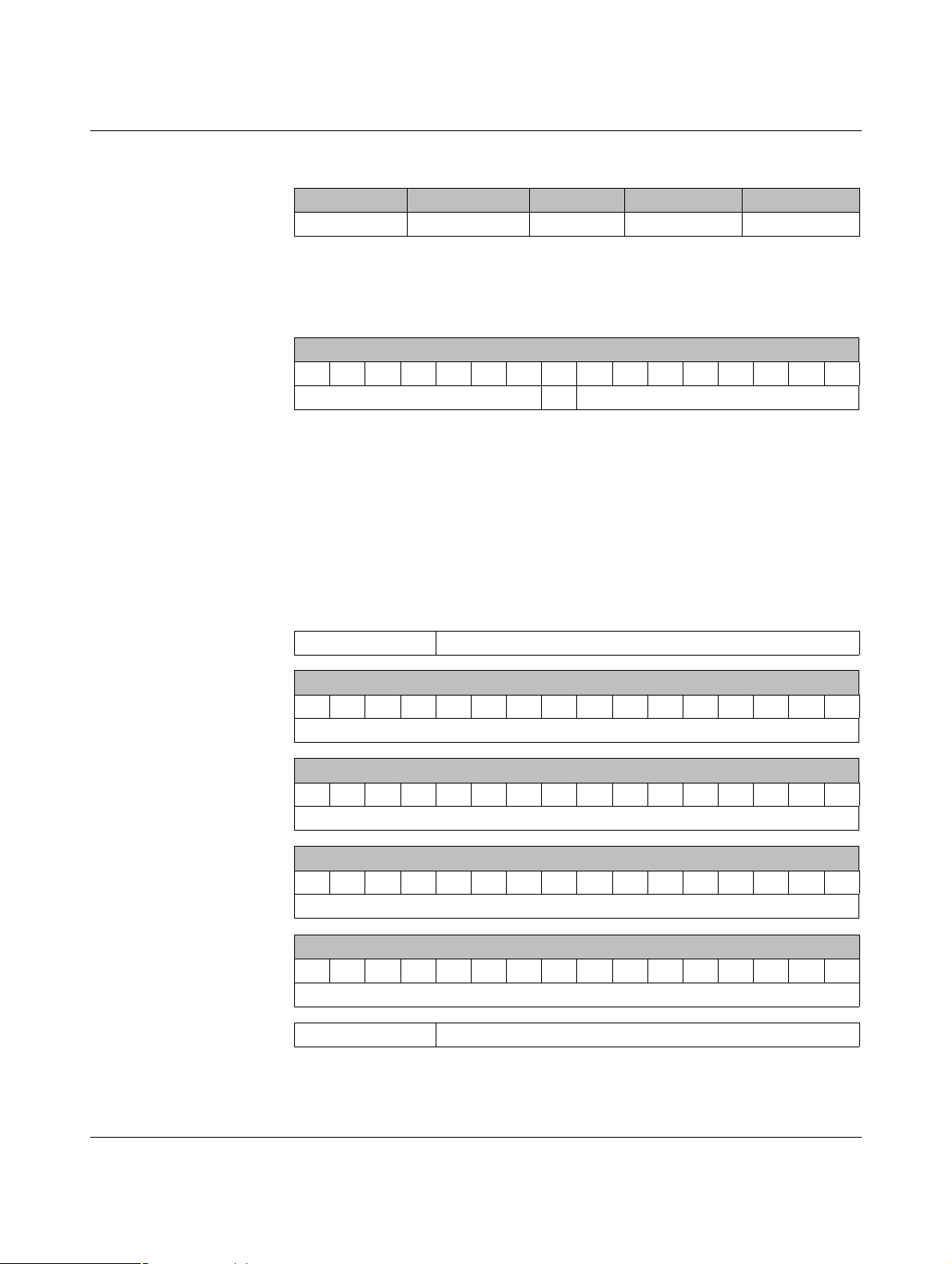
PLC/Modbus RTU mode
7.6.1 RAD-AI4-IFS process data
I/O module Module type ID Register Address range Function code
RAD-AI4-IFS 20
1
xx = I/O MAP address set using the white thumbwheel
hex
06
hex
30xx0 ... 30xx5
Table 7-8 RAD-AI4-IFS module type and currentness of data
1
30xx0
Module type and currentness of data
15 14 13 12 11 10 09 08 07 06 05 04 03 02 01 00
2
Y
1
xx = I/O MAP address set using the white thumbwheel
2
Y = currentness of data, bit 8
Module type
If the data in the register is not up to date, then the register value is 1. This is the
case, for example, if the wireless connection or communication with an input module fails. In this case, the input process data is retained in the Modbus table, but is
no longer updated.
3
If the module type in the register is invalid or unavailable, then the register value
is 0.
1
fc 04
3
30xx1 Reserved
30xx2 Analog input 1 (terminal point 2.x)
15 14 13 12 11 10 09 08 07 06 05 04 03 02 01 00
AI1
30xx3 Analog input 2 (terminal point 3.x)
15 14 13 12 11 10 09 08 07 06 05 04 03 02 01 00
AI2
30xx4 Analog input 3 (terminal point 4.x)
15 14 13 12 11 10 09 08 07 06 05 04 03 02 01 00
AI3
30xx5 Analog input 4 (terminal point 5.x)
15 14 13 12 11 10 09 08 07 06 05 04 03 02 01 00
AI4
30xx6 ... 30xx9 Reserved
105542_en_02 PHOENIX CONTACT 73
Page 74

RAD-....-IFS
7.6.2 RAD-PT100-4-IFS process data
I/O module Module type ID Register Address range Function code
RAD-PT100-4-IFS 21
1
xx = I/O MAP address set using the white thumbwheel
hex
06
hex
30xx0 ... 30xx5
Table 7-9 RAD-PT100-4-IFS module type and currentness of data
1
30xx0
Module type and currentness of data
15 14 13 12 11 10 09 08 07 06 05 04 03 02 01 00
2
Y
1
xx = I/O MAP address set using the white thumbwheel
2
Y = currentness of data, bit 8
Module type
If the data in the register is not up to date, then the register value is 1. This is the
case, for example, if the wireless connection or communication with an input module fails. In this case, the input process data is retained in the Modbus table, but is
no longer updated.
3
If the module type in the register is invalid or unavailable, then the register value
is 0.
1
fc 04
3
30xx1 Reserved
30xx2 Pt 100 input 1 (terminal point 2.x)
15 14 13 12 11 10 09 08 07 06 05 04 03 02 01 00
T1
30xx3 Pt 100 input 2 (terminal point 3.x)
15 14 13 12 11 10 09 08 07 06 05 04 03 02 01 00
T2
30xx4 Pt 100 input 3 (terminal point 4.x)
15 14 13 12 11 10 09 08 07 06 05 04 03 02 01 00
T3
30xx5 Pt 100 input 4 (terminal point 5.x)
15 14 13 12 11 10 09 08 07 06 05 04 03 02 01 00
T4
30xx6 ... 30xx9 Reserved
74
PHOENIX CONTACT 105542_en_02
Page 75

PLC/Modbus RTU mode
7.6.3 RAD-AO4-IFS process data
I/O module Module type ID Register Address range Function code
RAD-AO4-IFS 30
1
xx = I/O MAP address set using the white thumbwheel
hex
06
hex
40xx0 ... 40xx5
Table 7-10 RAD-AO4-IFS module type and currentness of data
1
40xx0
Module type and currentness of data
15 14 13 12 11 10 09 08 07 06 05 04 03 02 01 00
2
Y
1
xx = I/O MAP address set using the white thumbwheel
2
Y = currentness of data, bit 8
Module type
If the data in the register is not up to date, then the register value is 1. If the process
data has been written to one of the registers, then the register value is 0. The register value then remains 0 for the entire operating time of the device.
3
If the module type in the register is invalid or unavailable, then the register value
is 0.
1
fc 03, 16
3
40xx1 Reserved
40xx2 Analog output 1 (terminal point 2.x)
15 14 13 12 11 10 09 08 07 06 05 04 03 02 01 00
AO1
40xx3 Analog output 2 (terminal point 3.x)
15 14 13 12 11 10 09 08 07 06 05 04 03 02 01 00
AO2
40xx4 Analog output 3 (terminal point 4.x)
15 14 13 12 11 10 09 08 07 06 05 04 03 02 01 00
AO3
40xx5 Analog output 4 (terminal point 5.x)
15 14 13 12 11 10 09 08 07 06 05 04 03 02 01 00
AO4
40xx6 ... 40xx9 Reserved
105542_en_02 PHOENIX CONTACT 75
Page 76

RAD-....-IFS
7.6.4 RAD-DI4-IFS process data
I/O module Module type ID Register Address range Function code
RAD-DI4-IFS 01
1
xx = I/O MAP address set using the white thumbwheel
hex
02
hex
30xx0 ... 30xx1
Table 7-11 RAD-DI4-IFS module type and currentness of data
1
30xx0
Module type and currentness of data
15 14 13 12 11 10 09 08 07 06 05 04 03 02 01 00
2
Y
1
xx = I/O MAP address set using the white thumbwheel
2
Y = currentness of data, bit 8
Module type
If the data in the register is not up to date, then the register value is 1. This is the
case, for example, if the wireless connection or communication with an input module fails. In this case, the input process data is retained in the Modbus table, but is
no longer updated.
3
If the module type in the register is invalid or unavailable, then the register value
is 0.
1
fc 04
3
30xx1 Digital inputs
15 14 13 12 11 10 09 08 07 06 05 04 03 02 01 00
DI4 DI3 DI2 DI1
Terminal point
6.x 5.x 2.x 1.x
30xx2 ... 30xx9 Reserved
76
PHOENIX CONTACT 105542_en_02
Page 77

PLC/Modbus RTU mode
7.6.5 RAD-DI8-IFS process data
I/O module Module type ID Register Address range Function code
1
fc 04
3
RAD-DI8-IFS
1
xx = I/O MAP address set using the white thumbwheel
02
hex
Static mode
40
hex
Pulse counter
mode
40
hex
Pulse counter
mode
02
hex
Static inputs
06
hex
Pulse inputs
02
hex
Reset counter
states
30xx0 ... 30xx1
30xx0 ... 30xx51fc 04
40xx0 ... 40xx11fc 03, 16
Table 7-12 RAD-DI8-IFS module type and currentness of data
1
30xx0
Module type and currentness of data
15 14 13 12 11 10 09 08 07 06 05 04 03 02 01 00
2
Y
1
xx = I/O MAP address set using the white thumbwheel
2
Y = currentness of data, bit 8
Module type
If the data in the register is not up to date, then the register value is 1. This is the
case, for example, if the wireless connection or communication with an input module fails. In this case, the input process data is retained in the Modbus table, but is
no longer updated.
3
If the module type in the register is invalid or unavailable, then the register value
is 0.
105542_en_02 PHOENIX CONTACT 77
Page 78

RAD-....-IFS
30xx1 Digital inputs DI1 ... DI8 (static mode)
15 14 13 12 11 10 09 08 07 06 05 04 03 02 01 00
DI8 DI7 DI6 DI5 DI4 DI3 DI2 DI1
Terminal point
5.x 5.x 4.x 4.x 3.x 3.x 2.x 2.x
30xx2 DI1: 32-bit pulse input, pulse counter mode
(terminal point 2.x)
15 14 13 12 11 10 09 08 07 06 05 04 03 02 01 00
Counter state DI1, low word
30xx3 DI1: 32-bit pulse input, pulse counter mode
(terminal point 2.x)
31 30 29 28 27 26 25 24 23 22 21 20 19 18 17 16
Counter state DI1, high word
30xx4 DI7: 32-bit pulse input, pulse counter mode
(terminal point 5.x)
15 14 13 12 11 10 09 08 07 06 05 04 03 02 01 00
Counter state DI7, low word
30xx5 DI7: 32-bit pulse input, pulse counter mode
(terminal point 5.x)
31 30 29 28 27 26 25 24 23 22 21 20 19 18 17 16
Counter state DI7, high word
30xx6 ... 30xx9 Reserved
40xx1 Reset counter states DI1/DI7
15 14 13 12 11 10 09 08 07 06 05 04 03 02 01 00
1
X
X
1
Bit 1 = 1: counter state DI7 reset to 0
2
Bit 0 = 1: counter state DI1 reset to 0
40xx2 ... 40xx9 Reserved
2
78
PHOENIX CONTACT 105542_en_02
Page 79

PLC/Modbus RTU mode
7.6.6 RAD-DOR4-IFS process data
I/O module Module type ID Register Address range Function code
RAD-DOR4-IFS 10
1
xx = I/O MAP address set using the white thumbwheel
hex
02
hex
40xx0 ... 40xx1
Table 7-13 RAD-DOR4-IFS module type and currentness of data
1
30xx0
Module type and currentness of data
15 14 13 12 11 10 09 08 07 06 05 04 03 02 01 00
2
Y
1
xx = I/O MAP address set using the white thumbwheel
2
Y = currentness of data, bit 8
Module type
If the data in the register is not up to date, then the register value is 1. If the process
data has been written to one of the registers, then the register value is 0. The value
then remains 0 for the entire operating time of the device.
3
If the module type in the register is invalid or unavailable, then the register value
is 0.
1
fc 03, 16
3
40xx1 Digital outputs
15 14 13 12 11 10 09 08 07 06 05 04 03 02 01 00
DO4DO3DO2DO
1
Terminal point
6.x 5.x 2.x 1.x
40xx2 ... 40xx9 Reserved
105542_en_02 PHOENIX CONTACT 79
Page 80

RAD-....-IFS
7.6.7 RAD-DO8-IFS process data
I/O module Module type ID Register Address range Function code
02
hex
40xx0 ... 40xx1
Outputs
RAD-DO8-IFS 11
hex
02
hex
30xx0 ... 30xx11fc 04
Short-circuit
detection
1
xx = I/O MAP address set using the white thumbwheel
Table 7-14 RAD-DO8-IFS module type and currentness of data
30xx0, 40xx0
1
Module type and currentness of data
15 14 13 12 11 10 09 08 07 06 05 04 03 02 01 00
2
Y
1
xx = I/O MAP address set using the white thumbwheel
2
Y = currentness of data, bit 8
Module type
If the data in the register is not up to date, then the register value is 1. If the process
data has been written to one of the registers, bit 8 in 40xx0 is set to 0. The value in
register 40xx0 then remains 0 for the entire operating time of the device.
However, in register 30xx0 bit 8 is reset to 1 as soon as the status of short-circuit
detection is not up to date. This is the case, for example, if communication with an
input module fails. In this case, the input process data is retained in the Modbus
table, but is no longer updated.
3
If the module type in the register is invalid or unavailable, then the register value
is 0.
1
fc 03, 16
3
30xx1 Short-circuit detection at the digital outputs
15 14 13 12 11 10 09 08 07 06 05 04 03 02 01 00
Reserved X
1
Bit 1 = 1: short circuit detected at one output or several outputs 5 ... 8.
2
Bit 0 = 1: short circuit detected at one output or several outputs 1 ... 4.
80
PHOENIX CONTACT 105542_en_02
1
2
X
Page 81

PLC/Modbus RTU mode
30xx2 ... 30xx9 Reserved
40xx1 Digital outputs DO1 ... DO8
Channel (high byte) Channel (low byte)
15 14 13 12 11 10 09 08 07 06 05 04 03 02 01 00
Reserved DO8DO7DO6DO5DO4DO3DO2DO
Terminal point
5.x 5.x 4.x 4.x 3.x 3.x 2.x 2.x
40xx2 ... 40xx9 Reserved
7.6.8 RAD-DAIO6-IFS process data
I/O module Module type ID Register Address range Function code
1
1
fc 04
fc 03, 16
RAD-DAIO6-IFS 60
1
xx = I/O MAP address set using the white thumbwheel
hex
03
hex
(inputs)
03
hex
(outputs)
30xx0 ... 30xx2
40xx0 ... 40xx2
2
Table 7-15 RAD-DAIO6-IFS module type and currentness of data
1
30xx0
Module type and currentness of data
15 14 13 12 11 10 09 08 07 06 05 04 03 02 01 00
2
Y
1
xx = I/O MAP address set using the white thumbwheel
2
Y = currentness of data, bit 8
Module type
3
If the data in the register is not up to date, then the register value is 1. If the process
data has been written to one of the registers, bit 8 in 40xx0 is set to 0. The value in
register 40xx0 then remains 0 for the entire operating time of the device. This is the
case, for example, if the wireless connection fails. The input process data is retained in the Modbus table, but is no longer updated.
3
If the module type in the register is invalid or unavailable, then the register value
is 0.
105542_en_02 PHOENIX CONTACT 81
Page 82

RAD-....-IFS
30xx1 Digital inputs
15 14 13 12 11 10 09 08 07 06 05 04 03 02 01 00
DI2 DI1
Terminal point
2.x 1.x
30xx2 Analog input (terminal point 3.x)
15 14 13 12 11 10 09 08 07 06 05 04 03 02 01 00
AI1
30xx3 ... 30xx9 Reserved
40xx1 Digital outputs
15 14 13 12 11 10 09 08 07 06 05 04 03 02 01 00
DO2DO
1
Terminal point
6.x 5.x
40xx2 Analog output (terminal point 4.x)
15 14 13 12 11 10 09 08 07 06 05 04 03 02 01 00
AO1
Terminal point
4.x
40xx3 ... 40xx9 Reserved
82
PHOENIX CONTACT 105542_en_02
Page 83

PLC/Modbus RTU mode
7.6.9 Complete overview of the Modbus memory map
I/O input data, address range 30010 ... 30999
Modbus function code 04
I/O output data, address range 40010 ... 40999
Modbus function code 03, 16
RAD-DAIO6-IFS RAD-DAIO6-IFS
I/O
MAP
30 xx 0
30 xx 1
High byte 15 ... 8 Low byte 7 ... 0
Currentness of data Module type ID
X X X X X X X X X X X X X X X X X X
DI
2 1 2 1
I/O
MAP
40 xx 0
40 xx 1
High byte 15 ... 8 Low byte 7 ... 0
Currentness of data Module type ID
X X X X
30 xx 2
X X X X X X X X X X X X X X X X X X X X X X X X X X X X X X X X
AI1
40 xx 2
30xx3 ... 30xx9 reserved 40xx3 ... 40xx9 reserved
RAD-DI4-IFS RAD-DOR4-IFS
I/O
MAP
30 xx 0
30 xx 1
High byte 15 ... 8 Low byte 7 ... 0
Currentness of data Module type ID
X X X X X X X X X X X X X X X X X X
DI4 ... DI1
X X X X X X X X
I/O
MAP
40 xx 0
40 xx 1
High byte 15 ... 8 Low byte 7 ... 0
Currentness of data Module type ID
30xx2 ... 30xx9 reserved 40xx2 ... 40xx9 reserved
DO
AO1
DO4 ... DO1
RAD-DI8-IFS RAD-DI8-IFS
I/O
MAP
30 xx 0
30 xx 1
High byte 15 ... 8 Low byte 7 ... 0
Currentness of data Module type ID
X X X X X X X X X X X X X X X X X X
DI8 ... DI1
I/O
MAP
40 xx 0
40 xx 1
High byte 15 ... 8 Low byte 7 ... 0
Currentness of data Module type ID
Bit 0 = 1: reset DI1
Bit 1 = 1: reset DI7
X X X X X X X X X X
30 xx 2
30 xx 3
30 xx 4
30 xx 5
X X X X X X X X X X X X X X X X
X X X X X X X X X X X X X X X X
X X X X X X X X X X X X X X X X
X X X X X X X X X X X X X X X X
Counter state DI1 (low word) 40xx2 ... 40xx9 reserved
Counter state DI1 (high word)
Counter state DI7 (low word)
Counter state DI7 (high word)
30xx6 ... 30xx9 reserved
105542_en_02 PHOENIX CONTACT 83
Page 84

RAD-....-IFS
I/O input data, address range 30010 ... 30999
Modbus function code 04
I/O output data, address range 40010 ... 40999
Modbus function code 03, 16
RAD-DO8-IFS RAD-DO8-IFS
I/O
MAP
30 xx 0
High byte 15 ... 8 Low byte 7 ... 0
Currentness of data Module type ID
X X X X X X X X X X X X X X X X X X
I/O
MAP
40 xx 0
High byte 15 ... 8 Low byte 7 ... 0
Currentness of data Module type ID
Short-circuit detection
30 xx 1
Bit 0: DO 1 ... 4, bit 1: 5 ... 8
40 xx 1
9 8 7 6 5 4 3 2 1
X X X X X X X X X X X
30xx2 ... 30xx9 reserved 40xx2 ... 40xx9 reserved
RAD-AI4-IFS RAD-AO4-IFS
I/O
MAP
30 xx 0
High byte 15 ... 8 Low byte 7 ... 0
Currentness of data Module type ID
X X X X X X X X X X X X X X X X X X
I/O
MAP
40 xx 0
High byte 15 ... 8 Low byte 7 ... 0
Currentness of data Module type ID
30 xx 1 Reserved 40 xx 1 Reserved
30 xx 2
30 xx 3
30 xx 4
30 xx 5
AI1
X X X X X X X X X X X X X X X X X X X X X X X X X X X X X X X X
AI2
X X X X X X X X X X X X X X X X X X X X X X X X X X X X X X X X
AI3
X X X X X X X X X X X X X X X X X X X X X X X X X X X X X X X X
AI4
X X X X X X X X X X X X X X X X X X X X X X X X X X X X X X X X
40 xx 2
40 xx 3
40 xx 4
40 xx 5
AO1
AO2
AO3
AO4
30xx6 ... 30xx9 reserved 40xx6 ... 40xx9 reserved
DO
84
PHOENIX CONTACT 105542_en_02
Page 85

PLC/Modbus RTU mode
I/O input data, address range 30010 ... 30999
Modbus function code 04
I/O output data, address range 40010 ... 40999
Modbus function code 03, 16
RAD-PT100-4-IFS
I/O
MAP
30 xx 0
High byte 15 ... 8 Low byte 7 ... 0
Currentness of data Module type ID
X X X X X X X X X
30 xx 1 Reserved
30 xx 2
30 xx 3
30 xx 4
30 xx 5
X X X X X X X X X X X X X X X X
X X X X X X X X X X X X X X X X
X X X X X X X X X X X X X X X X
X X X X X X X X X X X X X X X X
T1
T2
T3
T4
30xx6 ... 30xx9 reserved
Example for reading temperature T1 (I/O MAP = 02):
function code 04, start address 21 (hex15)
.... . . . .... . . .
.... . . . .... . . .
30 99 0 40 99 0
105542_en_02 PHOENIX CONTACT 85
Page 86

RAD-....-IFS
7.6.10 RSSI signal and error code registers
The RSSI values indicate the received signal strength on the wireless module. You can read
the RSSI values via the serial interface of the master wireless module (RAD ID = 01) using
Modbus/RTU commands. The RSSI values of all wireless modules in the network are within
address range 35001 ... 35250.
Table 7-16 RSSI signal and error code registers
Address range 35001 ... 35250
Modbus function code fc 04
Address Wireless module High byte Low byte, RSSI value
15 14 13 12 11 10 09 08 07 06 05 04 03 02 01 00
IFS
35001 RSSI - RAD ID = 1
Reserved
(master)
35002 RSSI - RAD ID = 2 Reserved XXXXXXXX
... ... Reserved XXXXXXXX
35250 RSSI - RAD ID = 250Reserved XXXXXXXX
Bit 08 = error on IFS bus
If an error is present on the IFS bus, the register value is 1 (e.g., local bus error, because the
input or output module is disconnected from the DIN rail connector). If no error is present on
the IFS bus, the register value is 0.
XXXXXXXX
– Bits 9 ... 15 are reserved.
–Values <255 indicate the RSSI value in -dBm.
– The value 255 means that the RSSI value is invalid or the device cannot be reached.
Example for reading the RSSI register of the station with RAD ID = 2:
Function code 04, start address 5001 (hex1389)
86
PHOENIX CONTACT 105542_en_02
Page 87

PLC/Modbus RTU mode
7.7 Error codes and formats for analog input and output values
The measured value is represented in bits 0 ... 15. Values greater than 8000
error.
RAD-AI4-IFS analog inputs
Table 7-17 Representation of RAD-AI4-IFS analog values
Data word
hex dec/error code 0mA...20mA 4 mA ... 20 mA
0000 0 0 mA 1770 6000 4 mA 4 mA
7530 30000 20 mA 20 mA
7F00 32512 21.67 mA 21.67 mA
8001 Overrange >21.67 mA >21.67 mA
8002 Open circuit - <3.2 mA
8080 Underrange <0 mA -
RAD-AO4-IFS analog outputs
Table 7-18 Representation of RAD-AO4-IFS analog values
Data word
hex dec/error code 0mA...20mA 0 V ... 10 V
0000 0 0 mA 0 V
7530 30000 20 mA 10 V
7F00 32512 21.67 mA 10.84 V
indicate an
hex
RAD-DAIO6-IFS analog inputs and outputs
Table 7-19 Representation of RAD-DAIO6-IFS analog values
Data word
hex dec/error code 0...20mA 4...20mA 0V...10V
0000 0 0 mA - 0 V
1770 6000 4 mA 4 mA 2 V
7530 30000 20 mA 20 mA 10 V
7F00 32512 21.67 mA 21.67 mA 10.84 V
8001 Overrange >21.67 mA >21.67 mA 8002 Open circuit - <3.2 mA 8080 Underrange <0 mA - -
105542_en_02 PHOENIX CONTACT 87
Page 88

RAD-....-IFS
Error codes and formats for Pt 100 values
Table 7-20 Representation of the RAD-PT100-4-IFS Pt 100 values
Data word RAD-PT100-4-IFS
Pt 100 input
RAD-AO4-IFS
analog output
hex dec/error code -50°C ... +250°C 0mA...20mA 0V...10V Possible cause
0000 0 -50°C 0 mA 0 V
7530 30000 +250°C 20 mA 10 V
7F00 32512 +275.12°C 21.67 mA 10.84 V
8001 Overrange
8002 Open circuit Sensor wired incorrectly,
measuring cable too long,
cable resistance too high
8080 Underrange
88
PHOENIX CONTACT 105542_en_02
Page 89

Description of I/O extension modules
IO-MAP
RAD-AI4-IFS
PW
R
D
A
T
E
R
R
1
2
3
4
O
FF
O
N
D
IP
-1
8
8
Pw
r
1
Pw
r
2
+I
1
+I
2
-I
1
-I
2
P
w
r
3
Pw
r
4
+I
3
+I
4
-I
3
-I
4
Pwr
1
Pwr
2
+I
1
+I
2
-I
1
-I
2
1
2
3
4
5
7
9
12
11
10
8
6
8 Description of I/O extension modules
8.1 RAD-AI4-IFS - analog extension module with four inputs
The RAD-AI4-IFS analog I/O extension module can process up to four input signals with
0/4 mA ... 20 mA. All inputs are electrically isolated from one another, from the supply voltage, and from the electronics.
A supply voltage of at least 12 V DC is available at connection terminal block PWR1 for passive sensors (see Figure 8-1, item 1).
8.1.1 Structure
Figure 8-1 RAD-AI4-IFS structure
Item Te rm i n a l
Designation
block
1 3.1/3.2/3.3 Analog input 2 for 2, 3, 4-wire measuring transducers
2 2.1/2.2/2.3 Analog input 1 for 2, 3, 4-wire measuring transducers
3 DIP switches for configuring the analog inputs (0 mA ... 20 mA, 4 mA ... 20 mA)
4 White thumbwheel for setting the I/O MAP address
5 Connection option for DIN rail connector
6DIN rail
7 Metal foot catch for DIN rail fixing
8 4.1/4.2/4.3 Analog input 3 for 2, 3, 4-wire measuring transducers
9 5.1/5.2/5.3 Analog input 4 for 2, 3, 4-wire measuring transducers
105542_en_02 PHOENIX CONTACT 89
10 ERR status LED, red (communication error)
11 DAT status LED, green (bus communication)
12 PWR status LED, green (supply voltage)
Page 90

RAD-...-IFS
3 Wire
PWR IN
Out
GND
2.1
2.2
2.3
2 Wire
PWR IN
Out
2.1
2.2
4 Wire
Out
GND
U
S
2.2
2.3
IO-MAP
µC
DCDCIFS
IFS
3.1
3.2
3.3
I
V
LOOP
PWR
2
+I
2
-I
2
4.1
4.2
4.3
V
LOOP
PWR
3
+I
3
-I
3
I
2.1
2.2
2.3
V
LOOP
PWR
1
+I
1
-I
1
I
5.1
5.2
5.3
V
LOOP
PWR
4
+I
4
-I
4
I
-I4+I4PWR4
-I3+I3PWR3
-I2+I2PWR2
-I1+I1PWR1
OFFON
DIP-1
1
2
3
4
PWR
DAT
ERR
44
3WR3
22
1WR1
8.1.2 Basic circuit diagram
Figure 8-2 Basic circuit diagram for the RAD-AI4-IFS
8.1.3 Setting the DIP switches
You can configure the input signals using the DIP switches on the front (0 mA ... 20 mA or
4 mA ... 20 mA). Any changes to the DIP switch settings will be applied immediately. In
PLC/Modbus RTU mode, the setting of the input signals is evaluated for error diagnostics.
When set to 4 mA ... 20 mA, for example, it is possible to detect an open circuit.
Figure 8-3 DIP switches of the RAD-AI4-IFS
Table 8-1 DIP switches of the RAD-AI4-IFS
DIP switches
Setting Input signal 1 2 3 4
Analog IN1
Analog IN2
Analog IN3
90
PHOENIX CONTACT 105542_en_02
Analog IN4
0 mA ... 20 mA OFF
4 mA ... 20 mA ON
0 mA ... 20 mA OFF
4 mA ... 20 mA ON
0 mA ... 20 mA OFF
4mA...20mA ON
0 mA ... 20 mA OFF
4mA...20mA ON
Page 91

Description of I/O extension modules
-I4+I4PWR4
-I3+I3PWR3
-I2+I2PWR2
-I1+I1PWR1
OFFON
DIP-1
1
2
3
4
PWR
DAT
ERR
44
3WR3
22
1WR1
8.1.4 Diagnostic LEDs
The RAD-AI4-IFS I/O extension module uses a total of three LEDs to indicate the operating
states.
Figure 8-4 Diagnostic LEDs of the RAD-AI4-IFS
PWR LED
The green PWR LED indicates the status of the supply voltage.
OFF No supply voltage
ON Supply voltage OK
DAT LED
The green DAT LED indicates the status of bus communication.
OFF No communication
Flashing Configuration and addressing mode
ON Cyclic data communication
ERR LED
The red ERR LED indicates the error status.
OFF No error
Flashing
Slow (1.4 Hz) I/O MAP address changed
Fast (2.8 Hz) No bus communication
ON Critical internal error
105542_en_02 PHOENIX CONTACT 91
Page 92

RAD-...-IFS
8.1.5 Setting the I/O MAP address
Use the thumbwheel to set the I/O MAP address. The extension module in the Radioline
wireless system is addressed using the I/O MAP address. Addresses 01 ... 99 (maximum)
can be assigned for the I/O extension modules in the entire wireless network.
Table 8-2 Setting the I/O MAP address for the RAD-AI4-IFS
Thumbwheel Description
01 ... 99 I/O MAP address
00 Delivery state
**, 1* ... 9* Setting not permitted
*1 ... *9 Interface system slave address, for use with other
Interface system (IFS) master devices
8.1.6 Process data in PLC/Modbus RTU mode
The process image of the I/O extension module consists of six data words. For additional
information, please refer to Section “RAD-AI4-IFS process data” on page 73.
I/O module Module type ID Register Address range Function code
RAD-AI4-IFS 20
hex
06
hex
30xx0 ... 30xx5 fc 04
92
PHOENIX CONTACT 105542_en_02
Page 93

Description of I/O extension modules
8.2 RAD-PT100-4-IFS - extension module with four temperature inputs
The RAD-PT100-4-IFS analog I/O extension module has four Pt 100 inputs for temperatures from -50°C ... +250°C. Pt 100 inputs T1 ... T4 can be mapped to analog outputs
I1/U1 ... I4/U4 of the RAD-AO4-IFS extension module. All inputs are electrically isolated
from one another, from the supply voltage, and from the remaining electronics.
Pt 100 resistance thermometers can be connected to the RAD-PT100-4-IFS I/O extension
module. The thermometers change their resistance according to the temperature. The
Pt 100 input signals are acquired by the RAD-PT100-4-IFS and mapped to proportional, analog voltage or current signals of the RAD-AO4-IFS output module.
Example: at a temperature of -50°C at the Pt 100 input, a current of 0 mA or a voltage of 0 V
is issued at the output module. At a temperature of 250°C at the Pt 100 input, a current of
20 mA or a voltage of 10 V is issued at the output.
Table 8-3 Pt 100 input
Pt 100 input Analog output
-50°C 0 mA or 0 V
+250°C 20 mA or 10 V
105542_en_02 PHOENIX CONTACT 93
Page 94

RAD-...-IFS
µC
2.1
2.2
2.3
3.1
3.2
3.3
5.1
5.2
5.3
4.1
4.2
4.3
IO-MAP
0
1
DC
DC
IFS
IFS
A
D
1mA
A
D
1mA
A
D
1mA
A
D
1mA
-I2
-U2
+I2
+I1
-U1
-I1
+I3
-U3
-I3
+I4
-U4
-I4
RL
RL
I+
I–
RTD
ϑ
µC
2.1
2.2
2.3
3.1
3.2
3.3
5.1
5.2
5.3
4.1
4.2
4.3
IO-MAP
0
1
DC
DC
IFS
IFS
A
D
1mA
A
D
1mA
A
D
1mA
A
D
1mA
-I2
-U2
+I2
+I1
-U1
-I1
+I3
-U3
-I3
+I4
-U4
-I4
RL
I+
RTD
ϑ
RL
I–
U–
8.2.1 Connecting sensors
You can connect 2-wire or 3-wire sensors to the extension module. Take the measuring errors of the different measuring methods into consideration.
2-wire connection technology
2-wire connection technology is the most cost-effective connection technology. The temperature-related voltage is not directly measured at the sensor and is therefore falsified by
the two cable resistances R
surement useless. Please observe the diagrams in Section “Measuring errors when using
2-wire connection technology” on page 95.
For 2-wire connection technology, an insertion bridge is required between terminal blocks
x.2 and x.3.
. The measuring errors that occur may render the entire mea-
L
Figure 8-5 2-wire connection technology
3-wire connection technology
With 3-wire connection technology, the temperature-related voltage is measured several
times. Corresponding calculations additionally reduce the effect of the cable resistance on
the measurement result. The results are almost as good as those achieved with 4-wire connection technology.
The cable resistances R
at terminal blocks +I and -I must have the same value. This allows
L
you to subtract the established cable resistance from the measurement result and to get the
Pt 100 platinum resistance value.
94
PHOENIX CONTACT 105542_en_02
Figure 8-6 3-wire connection technology
Page 95

Description of I/O extension modules
µC
2.1
2.2
2.3
3.1
3.2
3.3
5.1
5.2
5.3
4.1
4.2
4.3
IO-MAP
0
1
DC
DC
IFS
IFS
A
D
1mA
A
D
1mA
A
D
1mA
A
D
1mA
-I2
-U2
+I2
+I1
-U1
-I1
+I3
-U3
-I3
+I4
-U4
-I4
RL
I+
(U+)
RTD
ϑ
RL
I–
U–
0 2,5 5 7,5 10 12,5 15 17,5 20
0
2
4
6
8
T [K]
I [m]
4-wire connection technology
The RAD-PT100-4-IFS does not support 4-wire connection technology.
• If you want to use a 4-wire sensor, only connect three of the four cables.
• The fourth cable should be left unwired. Otherwise there will be a different resistance in
the +I and -I cables owing to the parallel connection of two cable resistances.
Figure 8-7 4-wire connection technology
8.2.2 Measuring errors when using 2-wire connection
technology
105542_en_02 PHOENIX CONTACT 95
Figure 8-8 Systematic temperature measuring error ΔT depending on cable length l
Curves depending on cable cross section A
1 Temperature measuring error for A = 0.25 mm
2 Temperature measuring error for A = 0.5 mm
3 Temperature measuring error for A = 1.0 mm
4 Temperature measuring error for A = 1.5 mm
2
2
2
2
(Measuring error valid for: copper cable χ = 57 m/Ωmm2, TA = 25°C, and Pt 100 sensor)
Page 96

RAD-...-IFS
0 0,1 0,2 0,3 0,4 0,5 0,6 0,7 0,8 0,9 1,0
0
2
4
6
8
10
T [K]
A [mm ]
2
-50 -30 -10 10 30 50 70 90
0
0,5
1
1,5
2
2,5
T [K]
T [°C]
Figure 8-9 Systematic temperature measuring error ΔT depending on cable cross sec-
tion A
Figure 8-10 Systematic temperature measuring error ΔT depending on cable tempera-
ture T
A
(Measuring error valid for: copper cable χ = 57 m/Ωmm2, TA = 25°C, and Pt 100 sensor)
Make sure that the cable resistance and therefore the measuring error is as low as possible:
• Use sensor cables that are as short as possible.
2
• Avoid cable cross sections smaller than 0.5 mm
.
The temperature has only a small influence on the cable resistance.
You can calculate the cable resistance as follows:
R
= R
L
R
L
R
L
R
L20
x [1 + 0.00391x (TA - 20°C)]
L20
l
=
x [1 + 0.00391x (TA - 20°C)]
χ x A K
K
Cable resistance in Ω
Cable resistance at 20°C in Ω
l Cable length in m
χ Specific resistance of copper in m/Ωmm
A Cable cross section in mm
2
2
0.0039 1/K Temperature coefficient for copper (degree of purity of 99.99%)
T
A
Ambient temperature (cable temperature) in °C
Since there are two cable resistances in the measuring system, the value must be doubled.
Using the average temperature coefficient α =0.385Ω/K for Pt 100, the absolute measur-
ing error in Kelvin can be determined for platinum sensors according to DIN.
96
PHOENIX CONTACT 105542_en_02
Page 97

8.2.3 Structure
IO-MAP
RAD-PT100-4-IFS
P
W
R
DA
T
ERR
8
8
+I
1
+I
2
-U
1
-U
2
-I
1
-I
2
I
3
I
4
-U
3
-U
4
-I
3
-I
4
+I
1
+I
2
-U
1
-U
2
-I
1
-I
2
1
2
3
4
6
8
11
10
9
7
5
Figure 8-11 RAD-PT100-4-IFS structure
Description of I/O extension modules
Item Te rm i n a l
Designation
block
1 3.1/3.2/3.3 Pt 100 input 2 for 2 and 3-wire sensors
2 2.1/2.2/2.3 Pt 100 input 1 for 2 and 3-wire sensors
3 White thumbwheel for setting the I/O MAP address
4 Connection option for DIN rail connector
5DIN rail
6 Metal foot catch for DIN rail fixing
7 4.1/4.2/4.3 Pt 100 input 3 for 2 and 3-wire sensors
8 5.1/5.2/5.3 Pt 100 input 4 for 2 and 3-wire sensors
9 ERR status LED, red (communication error)
10 DAT status LED, green (bus communication)
11 PWR status LED, green (supply voltage)
105542_en_02 PHOENIX CONTACT 97
Page 98

RAD-...-IFS
2.1
2.3
+I
1
-I
1
3-wire
2.2
-U
1
µC
2.1
2.2
2.3
3.1
3.2
3.3
5.1
5.2
5.3
4.1
4.2
4.3
IO-MAP
0
1
DC
DC
IFS
IFS
A
D
1mA
A
D
1mA
A
D
1mA
A
D
1mA
-I2
-U2
+I2
+I1
-U1
-I1
+I3
-U3
-I3
+I4
-U4
-I4
2.1
2.3
+I
1
-I
1
2.2
+I
1
2-wire
8.2.4 Basic circuit diagram
Figure 8-12 Basic circuit diagram for the RAD-PT100-4-IFS
For 2-wire connection technology, an insertion bridge is required between terminal blocks
x.2 and x.3. In this case, the measuring accuracy is reduced (see “Measuring errors when
using 2-wire connection technology” on page 95).
98
PHOENIX CONTACT 105542_en_02
Page 99

Description of I/O extension modules
8.2.5 Diagnostic LEDs
The RAD-PT100-4-IFS I/O extension module uses a total of three LEDs to indicate the operating states.
Figure 8-13 Diagnostic LEDs of the RAD-PT100-4-IFS
PWR LED
The green PWR LED indicates the status of the supply voltage.
OFF No supply voltage
ON Supply voltage OK
DAT LED
The green DAT LED indicates the status of bus communication.
OFF No communication
Flashing Configuration and addressing mode
ON Cyclic data communication
ERR LED
The red ERR LED indicates the error status.
OFF No error
Flashing
Slow (1.4 Hz) I/O MAP address changed
Fast (2.8 Hz) No bus communication
ON Critical internal error
105542_en_02 PHOENIX CONTACT 99
Page 100

RAD-...-IFS
8.2.6 Setting the I/O MAP address
Use the thumbwheel to set the I/O MAP address. The extension module in the Radioline
wireless system is addressed using the I/O MAP address. Addresses 01 ... 99 (maximum)
can be assigned for the I/O extension modules in the entire wireless network.
Table 8-4 Setting the I/O MAP address for the RAD-PT100-4-IFS
Thumbwheel Description
01 ... 99 I/O MAP address
00 Delivery state
**, 1* ... 9* Setting not permitted
*1 ... *9 Interface system slave address, for use with other
Interface system (IFS) master devices
8.2.7 Process data in PLC/Modbus RTU mode
The process image of the I/O extension module consists of six data words. For additional
information, please refer to Section “RAD-PT100-4-IFS process data” on page 74.
I/O module Module type ID Register Address range Function code
RAD-PT100-4-IFS 21
hex
06
hex
30xx0 ... 30xx5 fc 04
8.3 RAD-AO4-IFS - analog extension module with four outputs
The RAD-AO4-IFS analog I/O extension module can output up to four input signals with
0/4 mA ... 20 mA. All outputs are electrically isolated from one another, from the supply voltage, and from the electronics.
Use either the current or voltage output at every analog channel.
100
PHOENIX CONTACT 105542_en_02
 Loading...