

Page 1
1Description
Patch panels
PP-RJ-...
© PHOENIX CONTACT
Data sheet
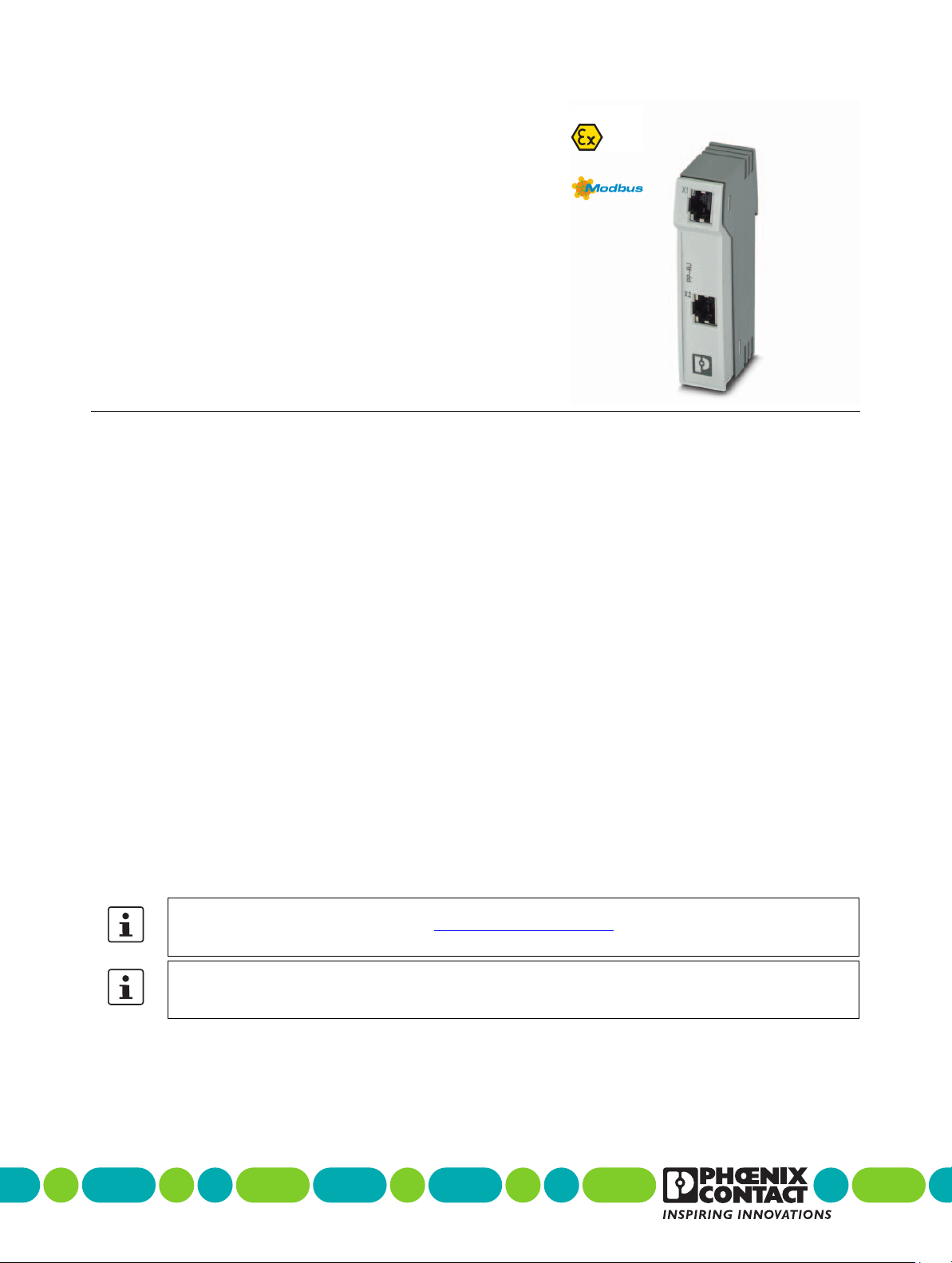
The component is an Ethernet patch panel for DIN rail
mounting. It represents the transition of the field cabling to
the internal control cabinet cabling.
The connection from the patch panel to the end device is
ensured with a prefabricated patch cable via the RJ45
socket (CAT5e).
Features
– 10/100/1000Mbps
– Mounting on a DIN rail
– Safe shield connection to ground potential
– Various connection options depending on the product
version
– RJ45 socket
–Screw terminal blocks
– Push-in connection
– IDC connection
Make sure you always use the latest documentation.
It can be downloaded from the product at phoenixcontact.net/products.
The PP-RJ... patch panels are compatible with the devices of the FL-PP... product family.
When replacing FL-PP... devices with PP-RJ... devices, strip an additional 1.4cm of the cable sheath away.
107962_en_01
2018-12-18
Page 2

2Table of contents
1 Description .............................................................................................................................. 1
2 Table of contents ..................................................................................................................... 2
3 Ordering data .......................................................................................................................... 3
4 Technical data ......................................................................................................................... 6
5 Safety regulations and installation notes.................................................................................. 8
5.1 Installation in Zone 2............................................................................................................. 8
5.2 UL notes............................................................................................................................ 9
6 Product description................................................................................................................ 10
6.1 Function elements ............................................................................................................. 11
7 Installation ............................................................................................................................. 12
7.1 Mounting ......................................................................................................................... 12
7.2 Removal.......................................................................................................................... 12
7.3 RJ45 interface .................................................................................................................. 12
7.4 Terminal assignment .......................................................................................................... 13
7.5 Stripping.......................................................................................................................... 13
7.6 Screw terminal blocks (only PP-RJ-SC)................................................................................... 13
7.7 Push-in terminal blocks (only PP-RJ-SCC) ............................................................................... 13
7.8 IDC terminal blocks (only PP-RJ-IDC) ..................................................................................... 14
7.9 Shield contacting with strain relief .......................................................................................... 14
PP-RJ-...
107962_en_01 PHOENIX CONTACT 2 / 15
Page 3

PP-RJ-...
3Ordering data
Description Ty p e Order No. Pcs./Pkt.
Patch panel, two RJ45 sockets, 10/100/1000Mbps,
DIN rail mounting, IP20
Patch panel, RJ45 socket on screw terminal blocks,
10/100/1000Mbps, DIN rail mounting, IP20,
shield contacting with strain relief
Patch panel, RJ45 socket on Push-in terminal blocks,
10/100/1000Mbps, DIN rail mounting, IP20,
shield contacting with strain relief
Patch panel, RJ45 socket on IDC terminal blocks,
10/100/1000Mbps, DIN rail mounting, IP20,
shield contacting with strain relief
Accessories Ty p e Order No. Pcs./Pkt.
Patch panel, two RJ45 sockets, 10/100/1000Mbps,
DIN rail mounting, IP20, shield current monitoring,
surge protection
Patch panel, RJ45 socket on screw terminal blocks,
10/100/1000Mbps, DIN rail mounting, IP20,
shield contacting with strain relief,
shield current monitoring, surge protection
Patch panel, RJ45 socket on Push-in terminal blocks,
10/100/1000Mbps, DIN rail mounting, IP20,
shield contacting with strain relief,
shield current monitoring, surge protection
Patch panel, RJ45 socket on IDC terminal blocks,
10/100/1000Mbps, DIN rail mounting, IP20,
shield contacting with strain relief,
shield current monitoring, surge protection
Crimping pliers, for assembling the RJ45 plugs
FL PLUG RJ45..., for assembly on site
CAT5-SF/UTP cable (J-02YS(ST)C HP 2 x 2 x 24 AWG),
heavy-duty installation cable, 2 x 2 x 0.22 mm², solid
conductor, shielded, outer sheath: 7.8 mm diameter, inner
sheath: 5.75 mm ±0.15 mm diameter cable, Ethernet
CAT5 (100 Mbps), 4-position, halogen-free compound,
HM 2 in acc. with VDE 0207, water blue RAL 5021,
cable length: Free input (0.25 ... 1000.0 m)
CAT5-SF/UTP cable (J-02YS(ST)C HP 2 x 2 x 24 AWG),
heavy-duty installation cable, 2 x 2 x 0.22 mm², solid
conductor, shielded, outer sheath: 7.8 mm diameter, inner
sheath: 5.75 mm ±0.15 mm diameter, preassembled on
both sides with RJ45 plug, crossover or line, network
cable, number of positions: 4, 100 Mbps, CAT5
PP-RJ-RJ 2703015 1
PP-RJ-SC 2703016 1
PP-RJ-SCC 2703018 1
PP-RJ-IDC 2703019 1
PP-RJ-RJ-F 2703020 1
PP-RJ-SC-F 2703021 1
PP-RJ-SCC-F 2703022 1
PP-RJ-IDC-F 2703023 1
FL CRIMPTOOL 2744869 1
FL CAT5 HEAVY 2744814 1
FL CAT5 HEAVY CONF/ 2744827 1
107962_en_01 PHOENIX CONTACT 3 / 15
Page 4

PP-RJ-...
Accessories Ty p e Order No. Pcs./Pkt.
CAT5-SF/UTP cable (J-LI02YS(ST)C H 2 x 2 x 26 AWG),
light-duty, flexible installation cable 2 x 2 x 0.14 mm²,
stranded, shielded, outer sheath: 5.75 mm ±0.15 mm
diameter
CAT5-SF/UTP cable (J-LI02YS(ST)C H 2 x 2 x 26 AWG),
light-duty, flexible installation cable 2 x 2 x 0.14 mm²,
stranded, shielded, outer sheath: 5.75 mm ±0.15 mm
diameter, preassembled on both sides with RJ45 plug,
crossover or line assignment, network cable, number of
positions: 4, 100 Mbps, CAT5
Actuation tool, for ST terminal blocks, also suitable for use
as a bladed screwdriver, size: 0.4 x 2.5 x 75 mm,
2-component grip, with non-slip grip
Passive network isolator for electrical isolation in Ethernet
networks. This protects Ethernet devices from potential
differences of up to 4 kV. Can be used for transmission
speeds of up to 100 Mbps. Connection using RJ45 and
COMBICON plug-in screw terminal block.
Passive network isolator for electrical isolation in Ethernet
networks. This protects Ethernet devices from potential
differences of up to 4 kV. Can be used for transmission
speeds of up to 100 Mbps. Possible to connect two RJ45
plugs.
Passive network isolator for electrical isolation in Ethernet
networks. This protects Ethernet devices from potential
differences of up to 4 kV. Can be used for transmission
speeds of up to 1 Gbps. Possible to connect two RJ45
plugs.
Passive network isolator for electrical isolation in Ethernet
networks. For the protection of Ethernet devices against
potential differences of up to 4 kV. Can be used for
transmission speeds of up to 100 Mbps. Ethernet
connection via two M12 sockets (D-coded).
Patch cable, CAT5, assembled, 0.3 m FL CAT5 PATCH 0,3 2832250 10
Patch cable, CAT5, assembled, 0.5 m FL CAT5 PATCH 0,5 2832263 10
Patch cable, CAT5, assembled, 1 m FL CAT5 PATCH 1,0 2832276 10
Patch cable, CAT5, assembled, 1.5 m FL CAT5 PATCH 1,5 2832221 10
Patch cable, CAT5, assembled, 2 m FL CAT5 PATCH 2,0 2832289 10
Patch cable, CAT5, assembled, 3 m FL CAT5 PATCH 3,0 2832292 10
Patch cable, CAT6, pre-assembled, 0.3 m FL CAT6 PATCH 0,3 2891181 10
Patch cable, CAT6, pre-assembled, 0.5 m FL CAT6 PATCH 0,5 2891288 10
Patch cable, CAT6, pre-assembled, 1.0 m FL CAT6 PATCH 1,0 2891385 10
Patch cable, CAT6, pre-assembled, 1.5 m FL CAT6 PATCH 1,5 2891482 10
Patch cable, CAT6, pre-assembled, 2.0 m FL CAT6 PATCH 2,0 2891589 10
Patch cable, CAT6, pre-assembled, 3.0 m FL CAT6 PATCH 3,0 2891686 10
Patch cable, CAT6, pre-assembled, 5.0 m FL CAT6 PATCH 5,0 2891783 10
FL CAT5 FLEX 2744830 1
FL CAT5 FLEX CONF/ 2744843 1
SZF 0-0,4X2,5 1204504 10
FL ISOLATOR 100-RJ/SC 2313928 1
FL ISOLATOR 100-RJ/RJ 2313931 1
FL ISOLATOR 1000-RJ/RJ 2313915 1
FL ISOLATOR 100-M12 2902985 1
107962_en_01 PHOENIX CONTACT 4 / 15
Page 5

PP-RJ-...
Accessories Ty p e Order No. Pcs./Pkt.
Patch cable, CAT6, pre-assembled, 7.5 m FL CAT6 PATCH 7,5 2891880 10
Patch cable, CAT6, pre-assembled, 10 m FL CAT6 PATCH 10 2891877 10
Patch cable, CAT6, pre-assembled, 12.5 m FL CAT6 PATCH 12,5 2891369 5
Patch cable, CAT6, pre-assembled, 15.0 m FL CAT6 PATCH 15,0 2891372 5
Patch cable, CAT6, pre-assembled, 20.0 m FL CAT6 PATCH 20,0 2891576 5
Stripping tool, for the multi-level stripping of shielded
cables
RJ45 connector, degree of protection: IP20, number of
positions: 8, 1 Gbps, CAT5 (IEC 11801:2002), material:
PA, connection method: IDC fast connection, connection
cross section: AWG 26- 23, cable outlet: straight, color:
traffic grey A RAL 7042
RJ45 connector, degree of protection: IP20, number of
positions: 8, 1 Gbps, CAT5 (IEC 11801:2002), material:
PA, connection method: IDC fast connection, connection
cross section: AWG 26- 23, cable outlet: straight, color:
black
Actuation tool, for ST terminal blocks, also suitable for use
as a bladed screwdriver, size: 0.4 x 2.5 x 75 mm,
2-component grip, with non-slip grip
Electronic diagonal cutter, tapered head, angled (21°),
without chamfer, with opening spring Diagonal cutter
Network cable, Ethernet CAT6A (10 Gbps), 8-position,
PUR halogen-free, water blue RAL 5021, shielded, free
cable end, on free cable end, cable length: Free entry
(0.5 ... 400 m)
VS-CABLE-STRIP-VARIO 1657407 1
VS-08-RJ45-5-Q/IP20 1656725 1
VS-08-RJ45-5-Q/IP20 BK 1658008 1
SZF 0-0,4X2,5 1204504 10
MICROFOX-SP 1212488 1
VS-OE-OE-94F/... 1417359 1
107962_en_01 PHOENIX CONTACT 5 / 15
Page 6

PP-RJ-...
4 Technical data
Ethernet interface, 10/100/1000Base-T(X) according to IEEE 802.3u
Connection method RJ45 socket Screw
Conductor cross section, flexible 0.14 mm² ...
Conductor cross section, flexible [AWG] 28 AWG ...
Conductor cross section, solid 0.14 mm² ...
Stripping length 5 mm 8 mm
Pin assignment 1:1 1:1 1:1 1:1
Torque 0.22 Nm ...
Wire diameter incl. insulation 1.6 mm
PP-RJ-RJ PP-RJ-SC PP-RJ-SCC PP-RJ-IDC
terminal block
1.5 mm²
16 AWG
1.5 mm²
0.25 Nm
Push-in
connection
0.2 mm² ...
1.5 mm²
26 AWG ...
16 AWG
0.2 mm² ...
1.5 mm²
IDC
connection
0.14 mm² ...
0.34 mm²
26 AWG ...
22 AWG
0.14 mm² ...
0.34 mm²
(Terminal block
is tested with
PVC insulation
- other
insulation
materials
available on
request)
Ethernet interface, 10/100/1000Base-T(X) according to IEEE 802.3u
Connection method RJ45 CAT5e
Maximum output power 60 W
Output nominal voltage < 60 V (ATEX approval)
< 57 V DC (with UL approval)
Maximum output current 725 mA (per channel)
Serial transmission speed 10/100/1000 Mbps
Transmission length 100 m (including patch cables)
Connection line twisted pair, shielded, CAT5 or better
Pin assignment 1:1
107962_en_01 PHOENIX CONTACT 6 / 15
Page 7

PP-RJ-...
General data
Degree of protection IP20 (manufacturer's declaration)
Rated insulation voltage 85 V DC
Mounting type DIN rail mounting, stationary
Dimensions (W/H/D) 23.8 mm x 101.3 mm x 50 mm
External cable diameter 5.5 mm ... 6.5 mm
Housing material Plastic gray
Vibration resistance in acc. with EN60068-2-6/
IEC60068-2-6
Shock in acc. with EN60068-2-27/IEC60068-2-27 25g for 11ms, three shocks in each direction
MTTF (mean time to failure) 105699 Years
Overvoltage category II
Degree of pollution 2
Ambient conditions
Ambient temperature (operation) -40 °C ... 75 °C
Ambient temperature (storage/transport) -40 °C ... 85 °C
Permissible humidity (operation) 10 % ... 95 % (non-condensing)
Altitude 5000 m (for restrictions see manufacturer's declaration)
10Hz...57Hz, amplitude ±3.5mm, 57Hz...150Hz, 5g
2000 m (ATEX approval)
Approvals / Certificates
Conformance CE-compliant
ATEX
II 3 G Ex nA IIC Gc U
Please follow the special installation instructions in the
documentation!
UL, USA UL60079-0 Ed.6 / UL60079-15 Ed.4
UL, Canada CSA22.2 No.60079-0 Ed.3 / CSA22.2 No.60079-15:16
Noxious gas test ISA-S71.04-1985 G3 Harsh Group A
107962_en_01 PHOENIX CONTACT 7 / 15
Page 8

5 Safety regulations and installation notes
5.1 Installation in Zone 2
CAUTION:
Observe the following safety notes when
using the device.
• The category 3 product can be installed in zone2
potentially explosive areas. It satisfies the demands of
the following standards:
–EN60079-0
–EN60079-15
– Comprehensive details are to be found in the EU
Declaration of Conformity which is enclosed and also
available on our website in the latest version.
• Installation, operation, and maintenance may only be
carried out by qualified electricians. Follow the
installation instructions as described.
• When installing and operating the device, the
applicable regulations and safety directives (including
national safety directives), as well as the generally
recognized codes of practice must be observed. The
safety-relevant data is included in this packing slip and
on the certificates (manufacturer's declaration,
additional approvals where applicable).
• Opening or modifying the product is prohibited. Do not
repair the product yourself; replace it with an equivalent
product instead. Repairs may only be carried out by the
manufacturer. The manufacturer is not liable for
damage resulting from non-compliance.
• The IP20 degree of protection (IEC60529/EN60529) of
the product is intended for a clean and dry environment.
Do not subject the product to mechanical and/or
thermal stress that exceeds the specified thresholds.
• The product is not designed for use in potentially dustexplosive atmospheres.
• The product must be stopped and immediately
removed from the Ex area if it is damaged, has been
subjected to an impermissible load, stored incorrectly,
or if it malfunctions.
• Only devices that are designed for operation in
• Connecting and disconnecting cables in the potentially
• For safe operation, lockable plug connections must
• Use a transient protection system which limits the
• The DIN rail must be connected to protective ground.
PP-RJ-...
WARNING: Explosion hazard when used
in potentially explosive areas
Please make sure that the following notes and
instructions are observed.
Ex Zone 2 and the conditions at the installation location
may be connected to the circuits in Zone 2.
explosive area and snapping devices onto and off of the
DIN rail is only permissible in a de-energized state or
when it has been ensured that an explosive atmosphere
is not present.
have a functional interlock (e.g. locking clip, screw
connection etc.). Insert the interlock. Repair any
damaged connectors immediately.
interference voltage to a maximum of 140% of the rated
voltage.
107962_en_01 PHOENIX CONTACT 8 / 15
Page 9
5.2 UL notes
U = max. 57 V DC
P = max. 60 W
Amb. Temp.: -40°C < T < 75°C
a
Class I, Zone 2, AEx nA IIC T4, Ex nA IIC Gc X T4
Class I, Division 2, Groups A, B, C and D
IND. CONT. EQ., ALSO
LISTED IND. CONT.
EQ. FOR HAZ. LOC.
E366272
INDUSTRIAL CONTROL EQUIPMENT FOR HAZARDOUS LOCATIONS
A)
B)
C)
D)
E)
F)
G)
This equipment must be mounted in an enclosure certified for use in Class I, Zone 2 minimum
and rated IP54 minimum in accordance with IEC 60529 when used in Class I, Zone 2
environment.
Device shall only be used in an area of not more than pollution degree 2.
If the equipment is used in a manner not specified, the protection provided by the equipment
may be impaired.
Minimum temperature rating of the cables to be connected to the field wiring terminals: 80°C
The external circuits connected to the terminal of the device must be supplied from SELV/PELV.
The device has to be built in the final safety enclosure, which has adequate rigidity according
to UL 61010-1, UL 61010-2-201 and meets the requirements with respect to spread of fire.
Use copper conductors only.
WARNING: Explosion hazard when used in potentially explosive areas
Please make sure that the following notes and instructions are observed.
PP-RJ-...
107962_en_01 PHOENIX CONTACT 9 / 15
Page 10
6Product description
101,3
23,6 55,2
62,7
101,3
23,6 55,2
62,7
PP-RJ-...
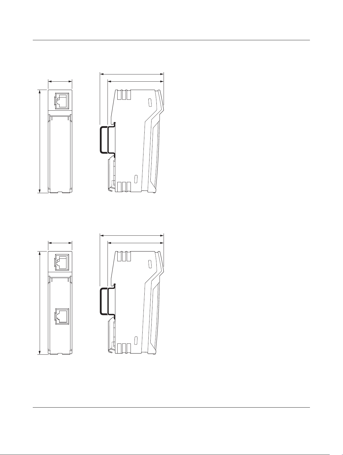
Figure 1 Dimensions
PP-RJ-RJ
Figure 2 Dimensions
107962_en_01 PHOENIX CONTACT 10 / 15
Page 11
6.1 Function elements
1
2
1
3
2
1
3
2
1
3
2
PP-RJ-...
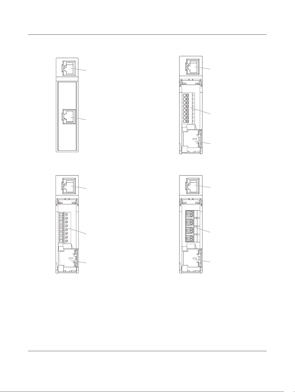
Figure 3 PP-RJ-RJ
Figure 4 PP-RJ-SC
Figure 5 PP-RJ-SCC
Figure 6 PP-RJ-IDC
1 X1 Shielded RJ45 socket (TP port)
2 X2 Port2 depending on product version, see
above
3 Shield contact spring (shield contacting with strain
relief)
107962_en_01 PHOENIX CONTACT 11 / 15
Page 12
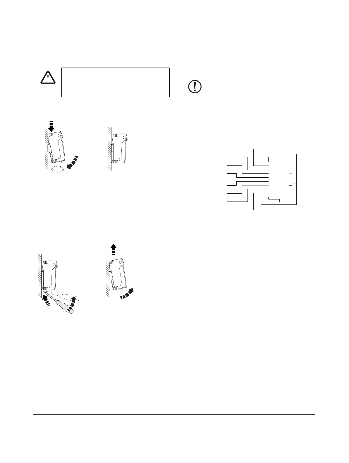
7 Installation
A
Click
B
A
B
C
D
1
2
3
4
5
6
7
8
RD
+
RD
-
TD
+
TD
-
n.c .
n.c .
n.c .
n.c .
RJ 45
WARNING: Explosion hazard when used
in potentially explosive areas
Only mount or remove the device when
disconnected from the voltage!
PP-RJ-...
7.3 RJ45 interface
NOTE: Interference
Only use shielded twisted pair cables and
corresponding shielded RJ45 connectors.
7.1 Mounting
Figure 7 Mounting on a DIN rail
The device is intended for installation in a control cabinet.
• Connect a 35mm ENDIN rail to the protective earth via
a grounding terminal block. The device is grounded by
snapping it onto the DIN rail.
• Snap the device onto the DIN rail.
7.2 Removal
• Only twisted pair cables with an impedance of 100Ω
can be connected to the RJ45 Ethernet interface.
• Insert the Ethernet cable with the RJ45 plug into the TP
interface until the plug engages audibly. Observe the
plug keying.
Figure 9 Pin assignment
Figure 8 Removal
• Push down the locking tab with a screwdriver, needlenose pliers or similar.
• Slightly pull the bottom edge of the device away from
the mounting surface.
• Pull the device away from the DIN rail.
107962_en_01 PHOENIX CONTACT 12 / 15
Page 13
PP-RJ-...
BU6
WH3
OG2
YE1
1 236
WH/BN7
GN6
BU4
WH/BU5
BN8
WH/GN3
OG2
WH/OG1
1 2364 578
TIA 568A
WH/BN7
OG6
BU4
WH/BU5
BN8
WH/OG3
GN2
WH/GN1
1 2364 578
Ethernet
TIA 568 B
PROFINET
1
2
3
6
1
2
3
6
4
5
7
8
1
2
3
6
4
5
7
8
TIA 568 A TIA 568 B PROFINET
>PC-FR<
c
b
a
c
b
a
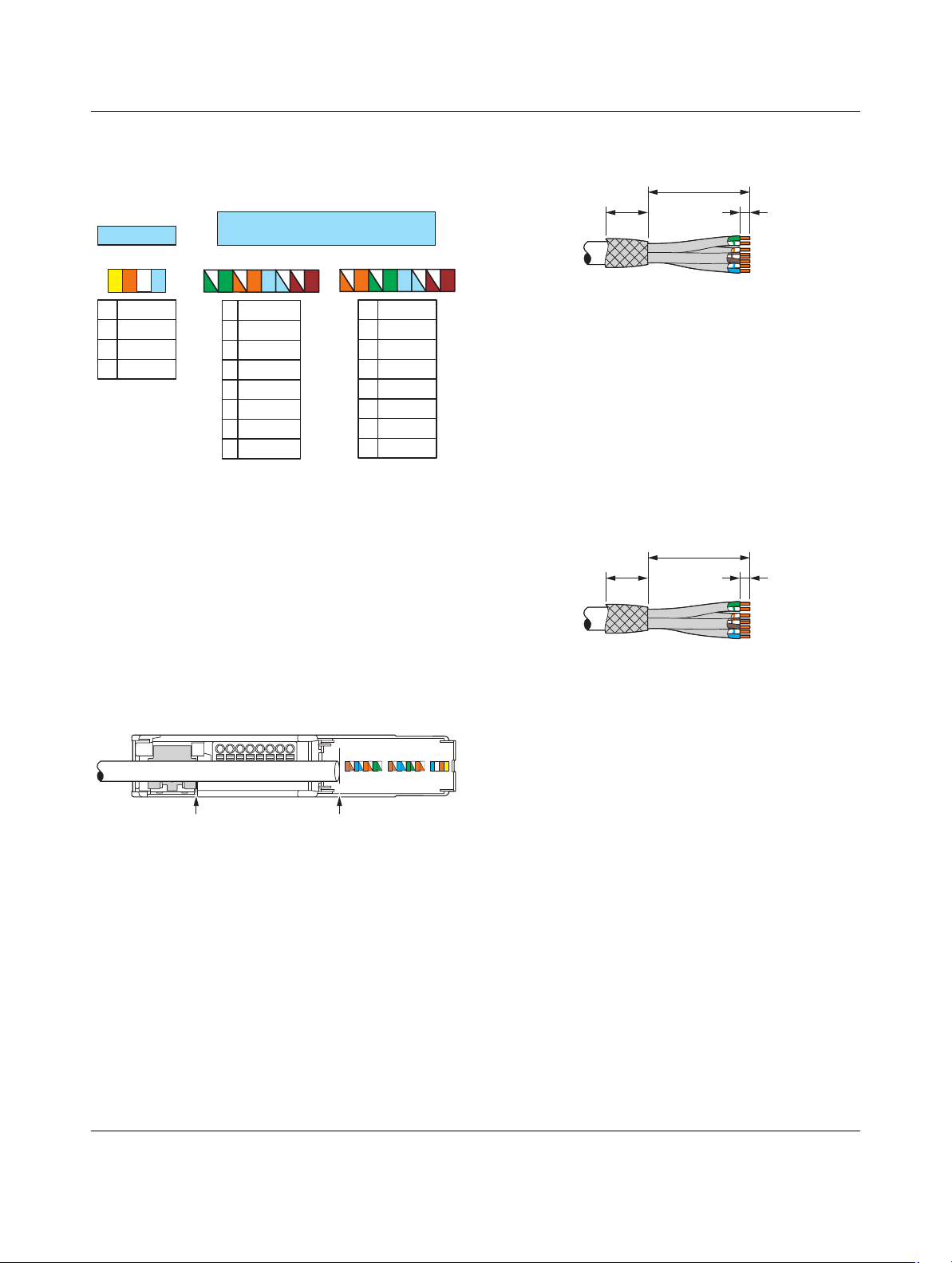
7.4 Terminal assignment
Terminal assignment for Ethernet (IEC 80.3u: TIA 568 A, TIA
568 B) and PROFINET
Figure 10 Terminal assignment
Key:
OG Orange
WH White
GN Green
YE Yellow
BU Blue
BN Brown
7.6 Screw terminal blocks (only PP-RJ-SC)
Figure 12 Stripping specifications
a20mm
b55mm
c5mm
• Strip off each individual wire to 5 mm.
• If possible, make sure that the individual wires remain
twisted up to the terminal blocks.
• Connect the single wires to the terminal blocks.
7.7 Push-in terminal blocks (only PP-RJ-SCC)
Figure 13 Stripping specifications
7.5 Stripping
a20mm
b55mm
c8mm
• Strip off each individual wire to 8 mm.
• If possible, make sure that the individual wires remain
twisted up to the terminal blocks.
Figure 11 Length for stripping
• Connect the single wires to the terminal blocks.
You can quickly determine the crimping length for the
product versions with connection terminal blocks:
• Open the cover.
• Place the cable end on the marking line ①.
• The edge of the shield contact spring ② indicates the
correct length for stripping (5.5cm).
• Strip the cable.
• Keep the aluminum foil on the single wires as far as
possible.
• Fold back 20mm of the braided shield backwards over
the outer sheath.
107962_en_01 PHOENIX CONTACT 13 / 15
Page 14
PP-RJ-...
ab
A
B
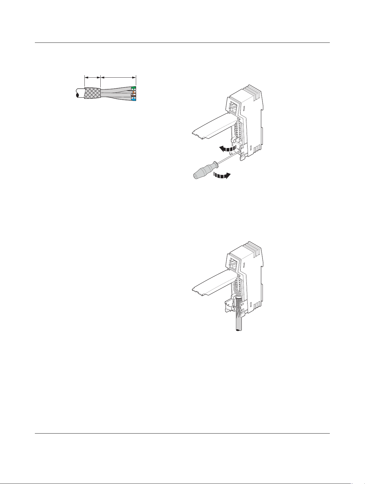
7.8 IDC terminal blocks (only PP-RJ-IDC)
Figure 14 Stripping specifications
a20mm
b55mm
• Open the connection terminal blocks.
• If possible, make sure that the individual wires remain
twisted up to the terminal blocks.
• Insert the single wires into the connection terminals as
far as they will go.
• Snap in the terminal blocks.
7.9 Shield contacting with strain relief
The product versions with connection terminal blocks are
equipped with built-in strain relief and shielding braid.
Figure 15 Open shield contact spring
• Open the shield contact spring.
• If the spring is latched in place, use a screwdriver to
open it.
Figure 16 Inserting the cable
• Place the cable with the folded braided shield into the
guiding shaft.
107962_en_01 PHOENIX CONTACT 14 / 15
Page 15
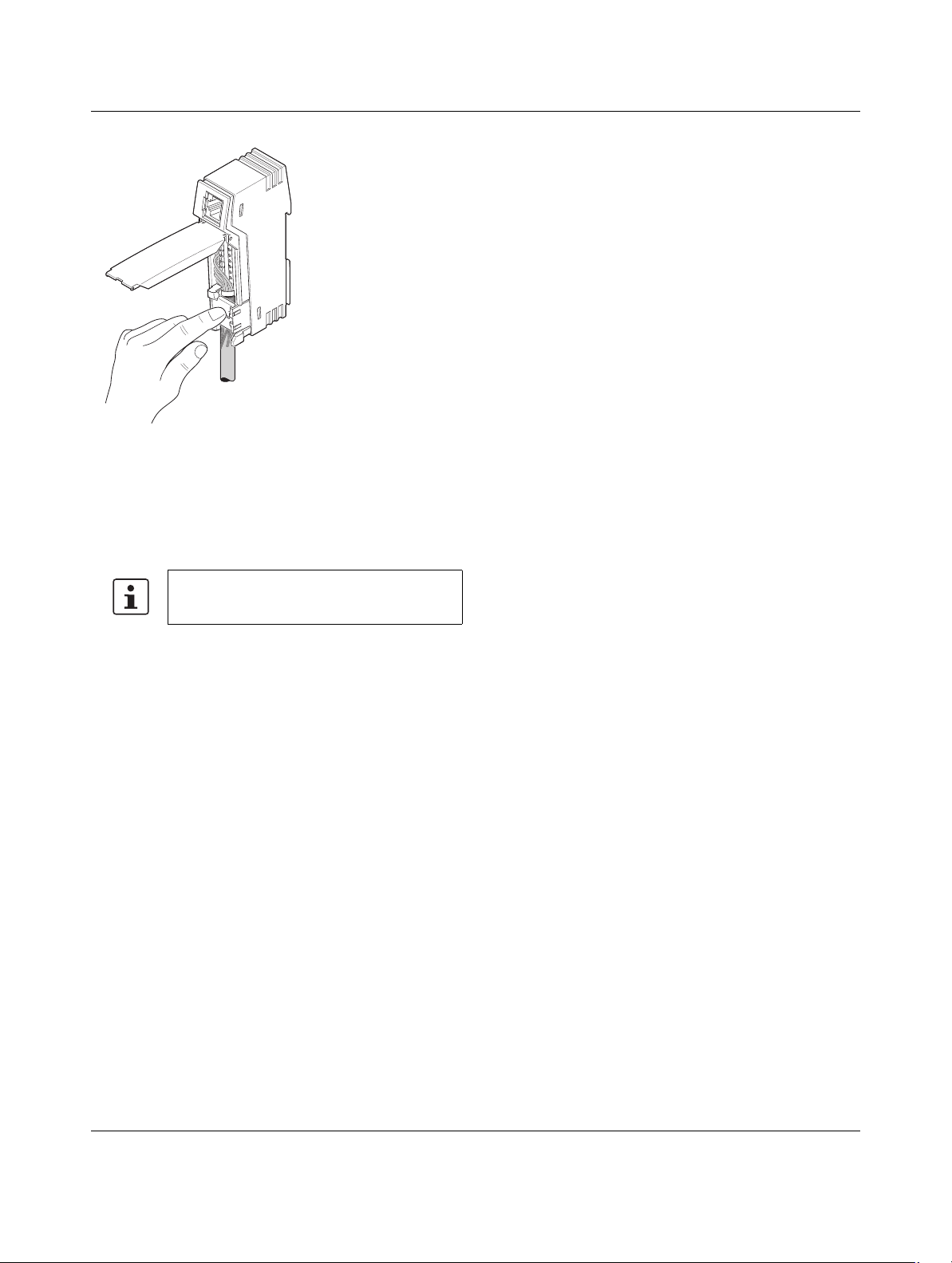
Figure 17 Close shield contact spring
• Snap in the shield contact spring. The braided shield is
pressed against the left side of the guiding shaft. This
establishes the shield contacting.
• Organize the wires so that you can close the cover.
PP-RJ-...
Fully snap in the foldable cover to prevent
unintentional opening.
107962_en_01 15 / 15
PHOENIX CONTACT GmbH & Co. KG • 32823 Blomberg • Germany
phoenixcontact.com
 Loading...