

Phoenix Contact MINI MCR-2-POT-UI, MINI MCR-2-POT-UI-PT, MINI MCR-2-POT-UI-C, MINI MCR-2-POT-UI-PT-C User guide [ml]
Page 1
PHOENIX CONTACT GmbH & Co. KG
Flachsmarktstraße 8, 32825 Blomberg, Germany
Fax +49-(0)5235-341200, Phone +49-(0)5235-300
MNR 9063889
phoenixcontact.com
MINI MCR-2-POT-UI 2902016
MINI MCR-2-POT-UI-PT 2902017
MINI MCR-2-POT-UI-C 2905005
MINI MCR-2-POT-UI-PT-C 2905006
6
4
7
8
9
10
11
3
12
21
5
PWR+
PWR–
+
+
–
–
passive
IN
OUT
FM
1 5
2 6
8
5
6
Zone 2
Sensor / Field PLC / DCS
3
4
7
S-Port
OUT U, I–
OUT U, I+
PWR+
PWR–
TI+
1
3
IN
IN
IN
2
active
A
D
C
B
E
MINI MCR-2-…
AWG 26-16
0,2-1,5 mm
2
10 mm
A
B
0,5-0,6 Nm
5-7 lb ln
B
A
MINI MCR-2-…-PT
A
AWG 26-12
0,2-2,5 mm
2
10 mm
DE Einbauanweisung für den Elektroinstallateur
FR Instructions d'installation pour l'électricien
2013-12-11
© PHOENIX CONTACT 2013
DNR 83147805 - 02PNR 105718 - 02
DEUTSCHDEUTSCHFRANÇAISFRANÇAIS
4. Installation
Die Belegung der Anschlussklemmen zeigt das Blockschaltbild. ()
Das Gerät ist auf alle 35-mm-Tragschienen nach EN60715 aufrastbar. Bei Einsatz
des Tragschienen-Busverbinders ME6,2TBUS-2 (Art.-Nr.: 2869728) legen Sie
diesen zur Brückung der Spannungsversorgung zuerst in die Tragschiene ein. ()
4.1 FASTCON Pro Stecker
Das Gerät verfügt über steckbare Anschlussklemmen mit integrierter
Messtrennklemme, wahlweise mit Push-in- oder Schraubanschlusstechnik.
Sie können die FASTCON Pro Stecker direkt und werkzeuglos stecken oder
ziehen. Mithilfe der integrierten Befestigungsschraube können Sie die Stecker
auch im angereihten Zustand bequem vom Modul lösen oder in die Trennposition
bringen.
Eine 4-fach Kodierung verhindert ein Falschstecken am Modul.
4.2 Spannungsversorgung
Sie haben folgende Möglichkeiten, die Module zu versorgen:
– Direkt über die Anschlussklemmen des Moduls, bei einer
Gesamtstromaufnahme der angereihten Module bis 400mA
Wir empfehlen, eine 630mA Sicherung (mittelträge oder träge) vorzuschalten.
– Über eine Einspeiseklemme (z.B. MINI MCR-2-PTB, Art.-Nr.: 2902066 oder
MINI MCR-2-PTB-PT, Art.-Nr.: 2902067)
– Über eine Systemstromversorgung MINI-SYS-PS-100-240AC/24DC/1.5 (Art.-
Nr: 2866983) oder MINI-PS-100-240AC/24DC/1.5/EX (Art.-Nr.: 2866653)
Beachten Sie zur Auslegung der Einspeisung unbedingt die "MACX und MINI
Analog Einspeiseanleitung".
4.3 Strommessung
Das Gerät ermöglicht die Strommessung ohne Auftrennen der Leiter durch
integrierte Messtrennklemmen. ()
Verwenden Sie für die Strommessung 2-mm-Messspitzen des Typs Fluke TL75-1
oder Messspitzen mit einer vergleichbaren Spitzenform.
Außerdem lassen sich gezielt einzelne Stromkreise auftrennen, zum Beispiel bei
Inbetriebnahmen.
Die Trennposition können Sie durch eine 180°-Drehung der integrierten
Befestigungsschraube einstellen. Die Trennposition wird über die Markierung an
den Steckern angezeigt. ()
ACHTUNG: Elektrostatische Entladung
Treffen Sie Schutzmaßnahmen gegen elektrostatische Entladung!
ACHTUNG
Beachten Sie unbedingt die Aufrastrichtung von MINI-Analog-Modul
und Tragschienen-Busverbinder: Rastfuß (D) unten und Steckerteil
(C) links!
ACHTUNG
Schließen Sie niemals die Versorgungsspannung direkt an den
Tragschienen-Busverbinder an! Die Ausspeisung von Energie aus
einzelnen Geräten ist nicht erlaubt!
Convertisseur de position du potentiomètre
1. Consignes de sécurité
1.1 Instructions d'installation
• Cet appareil de catégorie 3 est conçu pour être installé dans des atmosphères
explosibles de zone2. Il répond aux exigences des normes EN 60079-0:2012 et
EN 60079-15:2010.
• L’installation, l’utilisation et la maintenance doivent être confiées à un personnel
spécialisé dûment qualifié en électrotechnique. Respecter les instructions
d'installation. Lors de l’exécution et de l’exploitation, respecter les dispositions
et normes de sécurité en vigueur (ainsi que les normes de sécurité nationales)
de même que les règles généralement reconnues relatives à la technique. Les
caractéristiques relatives à la sécurité se trouvent dans ces instructions et les
certificats joints (attestation de conformité, autres homologations éventuelles).
• Des tensions dangereuses peuvent être présentes sur les éléments de
commande pendant le fonctionnement des appareils. Le paramétrage, le
raccordement de câbles ou l'ouverture du couvercle de module ne sont donc
autorisés qu'avec une installation hors tension, dans la mesure où il ne s'agit
uniquement de circuits électriques de type SELV- ou PELV-.
• L'ouverture ou la transformation de l'appareil ne sont pas admissibles. Ne
procédez à aucune réparation sur l'appareil, mais remplacez-le par un appareil
équivalent. Seul le fabricant est autorisé à effectuer des réparations sur
l’appareil. Le fabricant n’est pas responsable des dommages résultant
d’infractions à cette règle.
• L’indice de protection IP20 (CEI60529/EN60529) de l’appareil est valable dans
un environnement propre et sec. Ne pas soumettre l’appareil à des sollicitations
mécaniques et/ou thermiques dépassant les limites décrites.
• L’appareil n’est pas conçu pour être utilisé dans des atmosphères dangereuses
(poussière).
• L'appareil est conforme répond aux règlements relatifs aux parasites (CEM)
destinés au domaine industriel (catégorie de protectionA). L'utilisation dans une
zone d'habitation peut créer des parasites.
• Si l'appareil n'est pas utilisé conformément à la documentation, ceci peut
entraver la protection prévue.
• Prévoir si nécessaire le montage dans un boîtier à indice de protection adéquat
selon CEI 60529 pour protéger l'appareil contre les dommages mécaniques ou
électriques.
• Prévoir, à proximité de l'appareil, un commutateur/disjoncteur caractérisé
comme étant le dispositif de déconnexion de cet appareil.
• Prévoir un dispositif de protection contre les surintensités (I ≤ 4 A) dans
l'installation.
• Le boîtier de l'appareil lui confère une isolation de base vis-à-vis des appareils
voisins pour 150Veff. Il convient d'en tenir compte lors de l'installation de
plusieurs appareils côte à côte et d'installer une isolation supplémentaire si cela
est nécessaire.
• Les tensions appliquées à l'entrée, à la sortie et à l'alimentation sont des très
basses tensions. Selon l'application, il peut arriver qu'une tension dangereuse
(>30V) existe contre la terre. Dans ce cas, une isolation galvanique sûre avec
les autres raccordements existe.
• L'appareil doit être mis hors service s'il est endommagé, soumis à une contrainte
ou stocké de manière incorrecte, ou bien s'il présente des dysfonctionnements.
1.2 Installation en zone2
• Respecter les conditions définies pour l'utilisation en atmosphère explosible.
Lors de l’installation, utiliser un boîtier adapté et homologué (indice minimum de
protection IP54) qui répond aux exigences de la norme EN 60079-15. Respecter
également les exigences de la norme EN60079-14.
• Seuls les appareils destinés à être utilisés dans la zone Ex 2 et conçus pour être
utilisés conformément aux conditions présentes du lieu d'utilisation peuvent être
raccordés à des circuits de la zone 2.
• L’encliquetage, le désencliquetage sur le connecteur sur profilé et la connexion
et la déconnexion de câbles en atmosphère explosible sont uniquement
autorisés hors tension.
• L’appareil doit être mis hors serv ice et retiré immédiatement de la zone Ex s’il est
endommagé ou s’il a été soumis à des charges ou stocké de façon non
conforme, ou s’il présente un dysfonctionnement.
2. Brève description
Convertisseur à potentiomètre, à 3 voies isolées, configurable, à connectique
enfichable.
Les valeurs mesurées sont converties en un signal linéaire de courant ou de
tension, réglable au choix.
L'appareil peut au choix être configuré via des sélecteurs de codage (DIP) ou, à
l'aide de la fonctionnalité étendue, via le port S au moyen du logiciel standard
Analog-Conf, via FDT/DTM ou un autre accessoire au moyen de l'application pour
Smartphone MINI Analog Pro.
Si une utilisation complète de la plage du potentiomètre est impossible, il est
possible de déterminer la valeur inférieure et la valeur supérieure du potentiomètre
dans le logiciel lui-même.
L'appareil prend en charge la surveillance des défauts
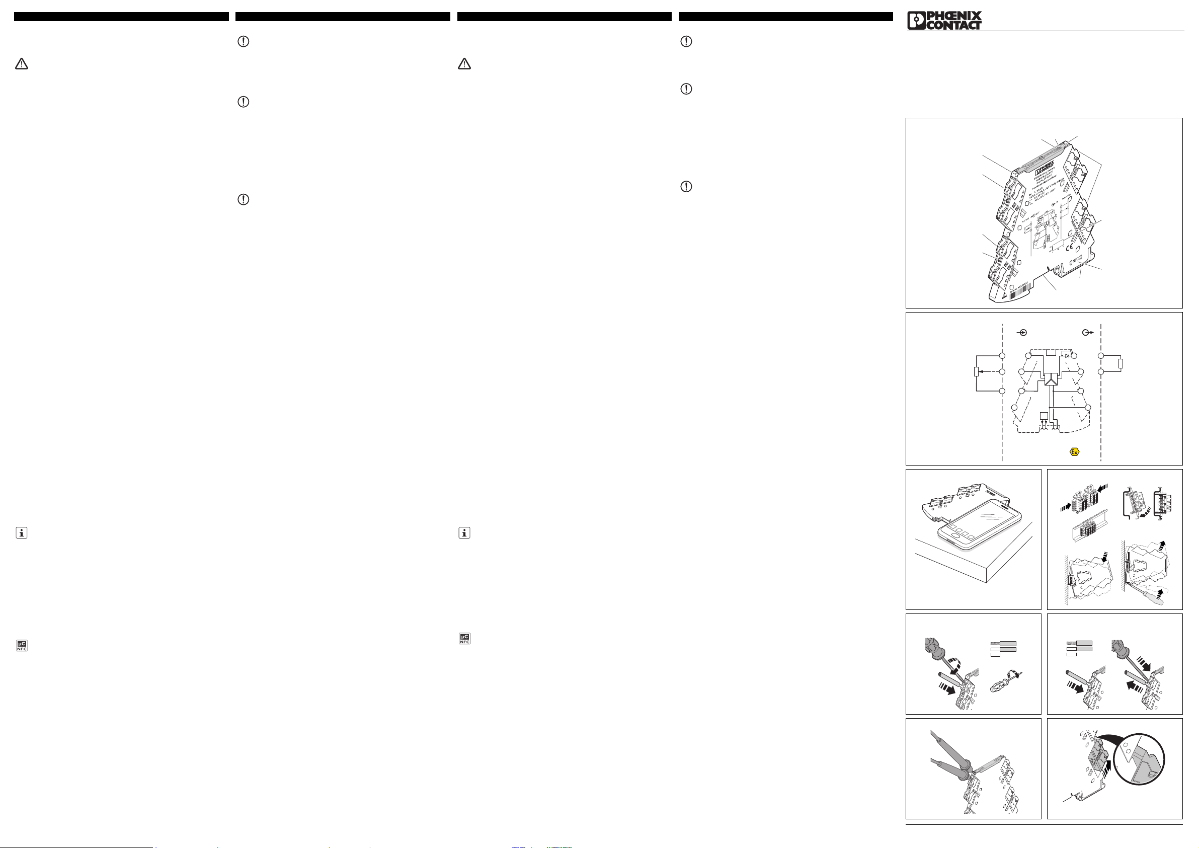
3. Eléments de commande et voyants ()
Les documents actuels peuvent être téléchargés à l'adresse
phoenixcontact.com.
Cet appareil permet la communication NFC.
A l'aide de l'application pour Smartphone MINI Analog Pro vous pouvez
configurer l'appareil, accéder à une aide au réglage des sélecteurs de
codage (DIP) et à de nombreuses informations relatives au module via
l'interface NFC du Smartphone.
L'application MINI Analog Pro pour Smartphone est disponible
gratuitement. ()
1 LED rouge affichage d'erreur
«ERR»
7 Pied universel encliquetable pour
profilés EN
2 LED verte «PWR», alimentation en
tension
8 Raccordement pour connecteur sur
profilé
3 Capot avec possibilité de repérage 9 Vis de fixation
4 Entrée: Potentiomètre 10 Tension d’alimentation
5 Sélecteur de codage (DIP) S1 11 Sortie: Signaux normalisés
6 Bobine NFC 12 Douille de mesure de courant
4. Installation
L'affectation des bornes de raccordement est illustrée dans le schéma de
connexion. ()
L'appareil est encliquetable sur tous les profilés 35mm conformes à EN60715. En
cas d'utilisation du connecteur sur profilé ME6,2TBUS-2 (réf.: 2869728), placer
d'abord le connecteur sur le profilé pour ponter l'alimentation en tension. ()
4.1 Connecteur FASTCON Pro
L'appareil dispose de bornes de raccordement enfichables à bloc de jonction
sectionnable à couteau, au choix en connectique push-in ou en connectique à vis.
Vous pouvez insérer ou retirer directement le connecteur FASTCON Pro sans
l'aide d'outil. A l'aide de la vis de fixation intégrée, vous pouvez facilement séparer
le connecteur du module ou l'amener en position de sectionnement même s'il est
juxtaposé.
Un détrompage quadruple évite tout enfichage incorrect sur le module.
4.2 Alimentation en tension
L'alimentation des modules peut être réalisée de l'une des manières suivantes:
– directement sur les bornes de raccordement du module, jusqu'à une
consommation totale de courant de 400mA des modules juxtaposés
Nous recommandons d'installer en amont un fusible de 630 mA (semi temporisé
ou temporisé).
– Via un module d’alimentation (MINI MCR-2-PTB, réf.: 2902066 ou MINI MCR-
2-PTB-PT, réf.: 2902067 p.ex.)
– Via une alimentation système MINI-SYS-PS-100-240AC/24DC/1.5 (réf.:
2866983) pu MINI-PS-100-240AC/24DC/1.5/EX (réf.: 2866653)
Respectez impérativement les «Consignes d'alimentation analogiques MACX et
MINI Analog» pour la conception de l'alimentation.
4.3 Mesure du courant
L'appareil permet de mesurer le courant sans devoir isoler les conducteur grâce
au bloc de jonction sectionnable à couteau intégré. ()
Pour mesurer le courant, utiliser uniquement des pointes de touche 2mm du type
Fluke TL75-1 ou des pointes de touche de forme similaire.
D'autre part, il est possible d'isoler précisément certains circuits électriques, par
exemple lors des mises en service.
La position de sectionnement se règle en faisant effectuer une rotation de 180° à
la vis de fixation intégrée. La position de sectionnement est indiquée par le
repérage situé sur les connecteurs. ()
IMPORTANT: décharge électrostatique
Prendre les mesures de protection appropriées contre les décharges
électrostatiques.
IMPORTANT
Respecter impérativement le sens d'encliquetage du module MINI
Analog et du connecteur sur profilé: pied encliquetable (D) en bas,
élément enfichable (C) à gauche!
IMPORTANT
Ne jamais raccorder la tension d'alimentation directement sur le
connecteur sur profilé. L'alimentation à partir de différents appareils
individuels est interdite.
Potipositionsmessumformer
1. Sicherheitshinweise
1.1 Errichtungshinweise
• Das Gerät der Kategorie 3 ist zur Installation im explosionsgefährdeten Bereich
der Zone 2 geeignet. Es erfüllt die Anforderungen der EN 6 0079-0:2012 und EN
60079-15:2010.
• Die Installation, Bedienung und Wartung ist von elektrotechnisch qualifiziertem
Fachpersonal durchzuführen. Befolgen Sie die beschriebenen
Installationsanweisungen. Halten Sie die für das Errichten und Betreiben
geltenden Bestimmungen und Sicherheitsvorschriften (auch nationale
Sicherheitsvorschriften), sowie die allgemein anerkannten Regeln der Technik
ein. Die sicherheitstechnischen Daten sind dieser Packungsbeilage und den
Zertifikaten (Konformitätsbewertung, ggf. weitere Approbationen) zu
entnehmen.
• Im Betrieb der Geräte können berührgefährliche Spannungen an den
Bedienelementen anliegen. Eine Parametrierung, das Anschließen von
Leitungen oder das Öffnen des Moduldeckels ist deshalb nur im
spannungslosen Zustand erlaubt, sofern es sich bei den angeschlossenen
Stromkreisen nicht ausschließlich um SELV- oder PELV-Stromkreise handelt.
• Öffnen oder Verändern des Gerätes ist nicht zulässig. Reparieren Sie das Gerät
nicht selbst, sondern ersetzen Sie es durch ein gleichwertiges Gerät.
Reparaturen dürfen nur vom Hersteller vorgenommen werden. Der Hersteller
haftet nicht für Schäden aus Zuwiderhandlung.
• Die Schutzart IP20 (IEC 60 529/EN 60529) des Gerätes ist für eine saubere und
trockene Umgebung vorgesehen. Setzen Sie das Gerät keiner mechanischen
und/oder thermischen Beanspruchung aus, die die beschriebenen Grenzen
überschreitet.
• Das Gerät ist nicht für den Einsatz in staubexplosionsgefährdeten Atmosphären
ausgelegt.
• Das Gerät erfüllt die Funkschutzbestimmungen (EMV) für den industriellen
Bereich (FunkschutzklasseA). Beim Einsatz im Wohnbereich kann es
Funkstörungen verursachen.
• Wenn das Gerät nicht entsprechend der Dokumentation benutzt wird, kann der
vorgesehene Schutz beeinträchtigt sein.
• Bauen Sie das Gerät zum Schutz gegen mechanische oder elektrische
Beschädigungen in ein entsprechendes Gehäuse mit einer geeigneten
Schutzart nach IEC 60529 ein.
• Sehen Sie in der Nähe des Gerätes einen Schalter/Leistungsschalter vor, der
als Trennvorrichtung für dieses Gerät gekennzeichnet ist.
• Sehen Sie eine Überstromschutzeinrichtung (I ≤ 4 A) in der Installation vor.
• Das Gerät besitzt durch sein Gehäuse eine Basisisolierung zu benachbarten
Geräten für 150V
eff
. Beachten Sie dieses bei der Installation mehrerer Geräte
nebeneinander und installieren Sie ggf. eine zusätzliche Isolation.
• Die an Eingang, Ausgang und Versorgung anliegenden Spannungen sind Extra-
Low-Voltage (ELV)-Spannungen. Es kann je nach Anwendung vorkommen,
dass eine gefährliche Spannung (>30V) gegen Erde anliegt. Für diesen Fall ist
eine sichere galvanische Trennung zu den anderen Anschlüssen vorhanden.
• Das Gerät ist außer Betrieb zu nehmen, wenn es beschädigt ist, unsachgemäß
belastet oder gelagert wurde bzw. Fehlfunktionen aufweist.
1.2 Installation in der Zone 2
• Halten Sie die festgelegten Bedingungen für den Einsatz in
explosionsgefährdeten Bereichen ein! Setzen Sie bei der Installation ein
geeignetes, zugelassenes Gehäuse der Mindestschutzart IP54 ein, das die
Anforderungen der EN60079-15 erfüllt. Beachten Sie auch die Anforderungen
der EN60079-14.
• An Stromkreise in der Zone 2 dürfen nur Geräte angeschlossen werden, welche
für den Betrieb in der Ex-Zone 2 und die am Einsatzort vorliegenden
Bedingungen geeignet sind.
• Das Auf- und Abrasten auf den Tragschienen-Busverbinder bzw. das
Anschließen und das Trennen von Leitungen im explosionsgefährdeten Bereich
ist nur im spannungslosen Zustand zulässig.
• Das Gerät ist außer Betrieb zu nehmen und unverzüglich aus dem Ex-Bereich
zu entfernen, wenn es beschädigt ist, unsachgemäß belastet oder gelagert
wurde bzw. Fehlfunktionen aufweist.
2. Kurzbeschreibung
Konfigurierbarer, 3-Wege getrennter Potenziometermessumformer mit steckbarer
Anschlusstechnik.
Die Messwerte werden in ein lineares und frei einstellbares Strom- oder
Spannungssignal umgeformt.
Sie können das Gerät wahlweise über DIP-Schalter konfigurieren, oder mit
erweiterter Funktionalität über den S-Port mittels der Standardsoftware AnalogConf, über FDT/DTM oder ohne weiteres Zubehör über die MINI Analog Pro
Smartphone App.
Wenn eine Vollausnutzung des Potenziometerbereiches nicht möglich ist, können
Sie den oberen und unteren Potenziometerwert in der Software selbst festlegen.
Das Gerät unterstützt Fault Monitoring.
3. Bedien- und Anzeigeelemente ()
Aktuelle Dokumente können Sie unter der Adresse phoenixcontact.com
herunterladen.
Dieses Gerät bietet die Möglichkeit der NFC-Kommunikation.
Mithilfe der MINI Analog Pro Smartphone App können Sie über die NFCSchnittstelle Ihres Smartphones das Gerät konfigurieren, eine DIP-Schalter
Einstellhilfe und umfangreiche Modulinformationen abrufen.
Die MINI Analog Pro Smartphone App steht Ihnen kostenlos zur Verfügung.
()
1 LED rot "ERR" Fehleranzeige 7 Universal-Rastfuß EN-
Tragschienen
2 LED grün "PWR"
Spannungsversorgung
8 Anschluss für Tragschienen-
Busverbinder
3 Abdeckung mit
Beschriftungsmöglichkeit
9 Befestigungsschraube
4 Eingang: Potenziometer 10 Versorgungsspannung
5 DIP-Schalter S1 11 Ausgang: Normsignale
6 NFC-Spule 12 Strommessbuchse
Page 2
98
DIP S1
1230456
0...20 mA
20...4 mA
OFF
A
B
C
D
NE43 upscale
NE43 downscale
NE43 0 mA
NE43 up-/downscale
OFF
OFF
ON
ON
ON
Line break dectection
Error
OUT
Automatic potentiometer detection
DIP config
Software/App config
Average
Default
0...10 V
10...0 V
4...20 mA
0...5 V
1...5 V
7
20...0 mA
0...20 mA
Line-break slider
21 mA
A
B
C
D
Line-break ,slider overrange, underrange, line-break pot
NE43
Error evaluation - Analog OUT
Upscale
Downscale
0mA
Up-/Downscale
= 21.5 mA
Line-break ,slider overrange, underrange, line-break pot
Line-break ,slider overrange, underrange ,line-break pot
Line-break slider
, line-break pot
3.5 mA
0mA
3.5 mA
= 21.5 mA
=
=
=
Overrange, underrange
Overrange and underrange signalisation only possible with Software/App configuration
Overrange
Underrange
20...0 mA 4...20 mA 20...4 mA
0...10 V 10...0 V 0...5 V 1...5 V
20.5 mA
0mA
21 mA
20.5 mA
0mA
21 mA
20.5 mA
4mA
21 mA
20.5 mA
4mA
10.5 V
10.25 V
0V
10.5 V
10.25 V
0V
5.25 V
5.125 V
0V
5.25 V
5.125 V
1V
Line-break slider
21 mA
Overrange
Underrange
20.5 mA
0mA
21 mA
20.5 mA
0mA
21 mA
20.5 mA
3.5 mA
21 mA
20.5 mA
3.5 mA
10.5 V
10.25 V
0V
10.5 V
10.25 V
0V
5.25 V
5.125 V
0V
5.25 V
5.125 V
0.875 V
Line-break slider
21 mA
Overrange
Underrange
20 mA
0mA
21 mA
20 mA
0mA
21 mA
20 mA
4mA
21 mA
20 mA
4mA
10.5 V
10 V
0V
10.5 V
10 V
0V
5.25 V
5V
0V
5.25 V
5V
1V
Line-break slider
0mA
Overrange
Underrange
20 mA
0mA
0mA
20 mA
0mA
4mA
20 mA
4mA
4mA
20 mA
4mA
0V
10 V
0V
0V
10 V
0V
0V
5V
0V
1V
5V
1V
(only OUT = 4...20 mA or 20...4 mA)
Line-break pot
0mA 0mA 4mA 4mA 0V 0V 0V 1V
Line-break pot
0 mA 0 mA 3 mA 3 mA 0 V 0 V 0 V 0.75 V
Line-break pot
21 mA 21 mA 21 mA 21 mA 10.5 V 10.5 V 5.25 V 5.25 V
Line-break pot
0mA 0mA 4mA 4mA 0V 0V 0V 1V
DEUTSCHDEUTSCHFRANÇAISFRANÇAIS
Caractéristiques techniques Technische Daten
Type de raccordement Anschlussart
Raccordement vissé Schraubanschluss MINI MCR-2-POT-UI 2902016
Raccordement vissé Schraubanschluss MINI MCR-2-POT-UI-C 2905005
Raccordement Push-in Push-in-Anschluss MINI MCR-2-POT-UI-PT 2902017
Raccordement Push-in Push-in-Anschluss MINI MCR-2-POT-UI-PT-C 2905006
Données d'entrée Eingangsdaten
Potentiomètre min./max. Potenziometer min./max. 0 ... 100 Ω / 0 ... 100 kΩ
Données de sortie Ausgangsdaten I U
Signal de sortie via sélecteur de codage (DIP) Ausgangssignal über DIP-Schalter 0 mA ... 20 mA 1 V ... 5 V
via sélecteur de codage (DIP) über DIP-Schalter 4 mA ... 20 mA 10 V ... 0 V
via sélecteur de codage (DIP) über DIP-Schalter 20 mA ... 0 mA 0 V ... 5 V
via sélecteur de codage (DIP) über DIP-Schalter 20 mA ... 4 mA 0 V ... 10 V
réglable par logiciel einstellbar über Software 0 mA ... 21 mA 0 V ... 10,5 V
Signal de sortie maximum Maximales Ausgangssignal 24,6 mA ca. 12,3 V
Charge R
B
Bürde R
B
≤ 600 Ω ≥ 10 kΩ
Courant de court-circuit Kurzschluss-Strom - < 31,5 mA
Tension de marche à vide Leerlaufspannung < 17,5 V Ondulation Ripple < 20 mV
SS
Caractéristiques générales Allgemeine Daten
Tension d'alimentation U
B
Versorgungsspannung U
B
24 V DC
Tension d'alimentation U
B
Versorgungsspannung U
B
9,6 V DC ... 30 V DC
Courant absorbé pour 24 V DC Stromaufnahme bei 24 V DC 30 mA
à 12 V DC bei 12 V DC 63 mA
Consommation de puissance pour I
OUT
= 20 mA, 9,6 V DC, charge 600 Ω Leistungsaufnahme bei I
OUT
= 20 mA, 9,6 V DC, 600 Ω Bürde ≤ 750 mW
Erreur de transmission max. R < 240 Ω = < 0,2 % Übertragungsfehler maximal R < 240 Ω = < 0,2 % < 0,1 %
Coefficient de température max. Temperaturkoeffizient maximal 0,01 %/K
Réponse indicielle (10-90%) Sprungantwort (10-90%) < 60 ms
Indice de protection Schutzart IP20
Plage de température ambiante Exploitation Umgebungstemperaturbereich Betrieb -40 °C ... 70 °C
Stockage/transport Lagerung/Transport -40 °C ... 85 °C
Humidité de l'air pas de condensation Luftfeuchtigkeit keine Betauung 5 % ... 95 %
Matériau du boîtier Gehäusematerial PBT
Dimensions l / H / P Abmessungen B / H / T 6,2 mm / 110,5 mm / 120,5 mm
Isolation galvanique Galvanische Trennung
Isolation renforcée selon CEI61010-1 Verstärkte Isolierung nach IEC 61010-1
Catégorie de surtension Überspannungskategorie II
Degré de pollution Verschmutzungsgrad 2
Tension d'isolement assignée Bemessungsisolationsspannung 300 V
Tension d'essai : entrée / sortie / alimentation Prüfspannung Eingang/Ausgang/Versorgung 3 kV (50 Hz, 1 min.)
Conformité / Homologations Conformité CE Konformität / Zulassungen CE-konform
ATEX ATEX
II 3 G Ex nA IIC T4 Gc X
Constructions navales GL demandé Schiffbau GL beantragt
UL, USA/Canada
508 Listed en cours
Class I, Div. 2, Groups A, B, C, D T5 en cours
UL, USA / Kanada
508 Listed beantragt
Class I, Div. 2, Groups A, B, C, D T5, beantragt
Conformité à la directive CEM 2004/108/CE Konformität zur EMV-Richtlinie 2004/108/EG
Emission selon Störabstrahlung nach EN 61000-6-4
Immunité De faibles écarts peuvent survenir lors de perturbations. Störfestigkeit Während der Störbeeinflussung kann es zu geringen Abweichungen kommen. EN 61000-6-2
4.4 Inscriptions
Pour le repérage des appareils, des étiquettes standards imprimables UCT-EM...
ou UC-EMLP sont disponibles (peuvent également être imprimées selon les
indications du client). De plus, les couvercles sont suffisamment larges pour
pouvoir utiliser tout type d'étiquette collante (SK 5,0 WH:REEL p. ex.) sans
recouvrir les LED des voyants de diagnostic.
4.5 Surveillance défauts FM
Les défaillances du module ou de l'alimentation, mais aussi les erreurs détectées
dans l'entrée de signal du module sont signalées via le connecteur sur profilé au
module de surveillance des défauts de même forme MINI MCR-2-FM-RC
(référence: 2904504) ou MINI MCR-2-FM-RC-PT (référence: 2904508). Ce
dernier signalise l'erreur en envoyant un message via un contact NF.
Un module de surveillance des défauts n'est nécessaire qu'une seule fois en
association. Une analyse isolée des amplificateurs-séparateurs MINI Analog Pro
(au maximum 115) est superflue.
Le comportement du contact de surveillance des erreurs en fonction des
différentes configurations des sélecteurs de codage (DIP) est indiqué dans le
tableau correspondant de la fiche technique disponible à l'adresse
phoenixcontact.net/products.
5. Configuration
L'appareil est livré dans la configuration standard suivante:
Détection automatique du potentiomètre activée; sortie 4...20mA; analyse des
défauts selon NE43 (downscale); le contact de surveillance des défauts réagit à
tous les défauts.
Une configuration peut également être réalisée sans tension d’alimentation.
Pour plus d'informations concernant les différentes configurations possibles,
consulter la fiche technique à l'adresse phoenixcontact.net/products.
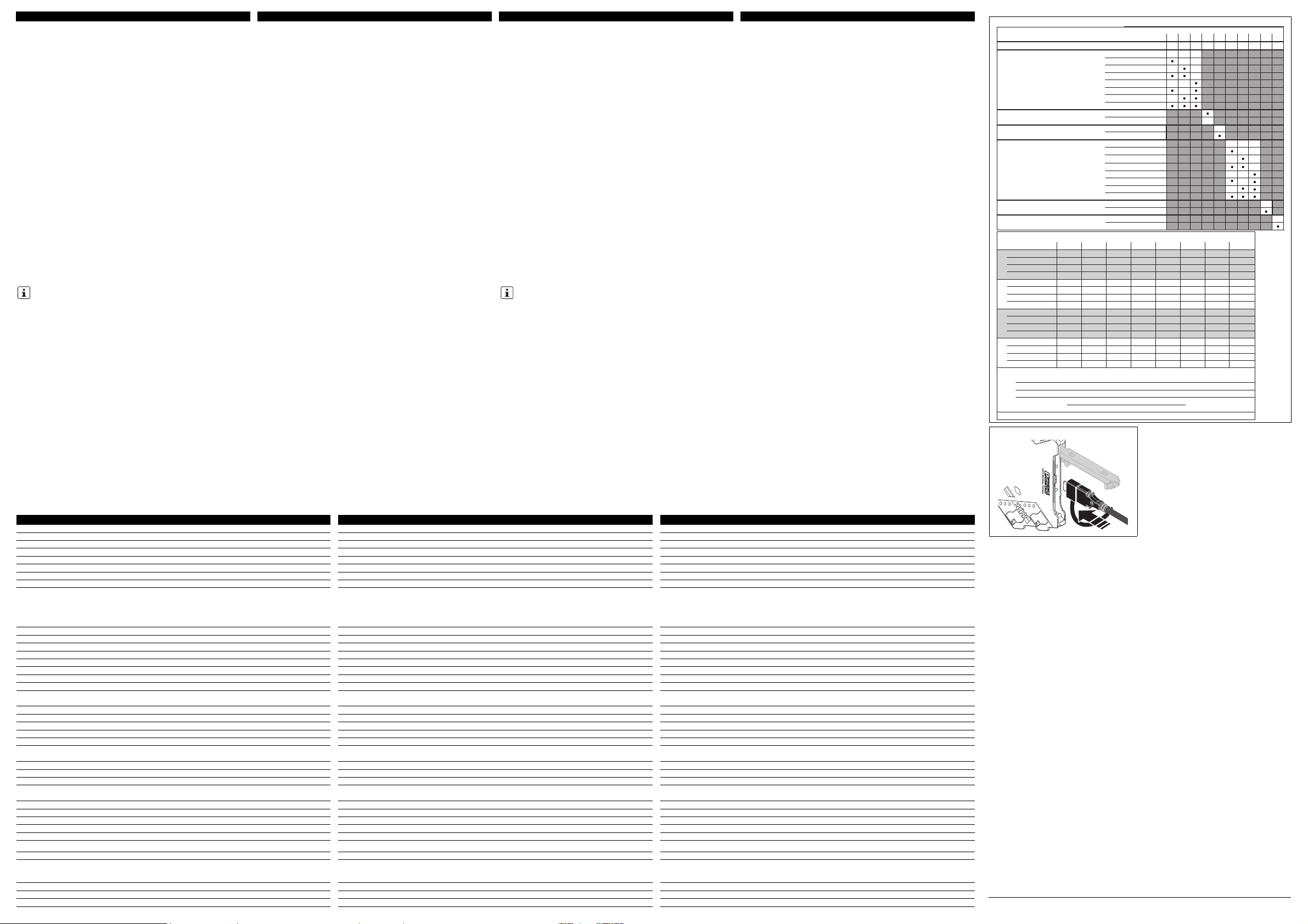
5.1 Configuration via sélecteur de codage (DIP) ()
À la livraison, tous les commutateurs DIP sont en position «OFF».
Configurer les commutateurs DIP conformément à l’application prévue à l’aide du
tableau ci-contre.
5.2 Configuration via logiciel
La configuration via logiciel met à disposition non seulement la configuration des
sélecteurs de codage (DIP), mais aussi des options étendues de configuration
ainsi qu'une fonction de surveillance.
Deux solutions logicielles gratuites sont disponibles sur Internet pour être
téléchargées.
– Logiciel standard ANALOG-CONF
– Solutions FTD/DTM: application cadre FTD et paquets DTM
5.3 Configuration via application MINI Analog Pro ()
La configuration via application dispose d'options de configuration étendues, en
plus de la configuration des sélecteurs de codage (DIP).
A l'aide de l'application MINI Analog Pro pour Smartphone, vous pouvez configurer
le module sans adaptateur de programmation supplémentaire, via l'interface NFC
du Smartphone, sans câble.
6. Voyants de diagnostic et d’état
Utiliser l'adaptateur de programmation IFS-USB-PROG-ADAPTER
(référence: 2811271) ou le NFC-USB-PROG-ADAPTER (référence:
2900013) pour raccorder l'appareil et le PC. ()
LED verte PWR Tension d’alimentation
Allumée Tension d'alimentation établie
LED rouge ERR Affichage d'erreur ou mode de simulation
Clignote
rapidement
(2,8Hz)
Erreur capteur ou configuration du sélecteur de
codage (DIP) erronée
Clignote lentement
(1,4Hz)
Mode simulation
Allumée Erreur interne d'appareil
4.4 Beschriftung
Zur Beschriftung der Geräte stehen - auch nach Kundenwunsch - bedruckbare
Standardbeschriftungsschildchen UCT-EM... oder UC-EMLP... zur Verfügung.
Außerdem bieten die Deckel ausreichend Platz zur Verwendung beliebiger
Klebeetiketten, zum Beispiel SK 5,0 WH:REEL, ohne dabei die LEDDiagnoseanzeigen zu verdecken.
4.5 Fault Monitoring FM
Neben einem Modul- oder Versorgungsausfall werden auch erkannte Fehler im
Signaleingang des Moduls über den Tragschienen-Busverbinder an das
konturgleiche Fault-Monitoring-Modul MINI MCR-2-FM-RC (Art.-Nr.: 2904504)
bzw. MINI MCR-2-FM-RC-PT (Art.-Nr.: 2904508) gemeldet. Dieses meldet den
Fehler zentral über einen Öffnerkontakt.
Ein Fault-Monitoring-Modul wird nur einmal im Verbund benötigt. Eine
Einzelauswertung der bis zu 115 aufgerasteten MINI Analog Pro Trennverstärker
entfällt.
Entnehmen Sie das Verhalten des Fault-Monitoring-Kontaktes bei den
verschiedenen DIP-Schalter-Konfigurationen der entsprechenden Tabelle im
Datenblatt unter phoenixcontact.net/products.
5. Konfiguration
Das Gerät wird mit folgender Standardkonfiguration ausgeliefert:
Automatische Potenziometererkennung aktiviert; Ausgang 4...20mA;
Fehlerauswertung nach NE43 (downscale); Fault-Monitoring-Kontakt reagiert bei
allen Fehlern.
Eine Konfiguration ist bei allen Konfigurationsvarianten ohne
Versorgungsspannung möglich.
Detailinformationen zu allen Konfigurationsvarianten finden Sie im Datenblatt
unter phoenixcontact.net/products.
5.1 Konfiguration über DIP-Schalter ()
Im Auslieferungszustand befinden sich alle DIP-Schalter in der Position "OFF".
Konfigurieren Sie die DIP-Schalter entsprechend der geplanten Anwendung mit
Hilfe nebenstehender Tabelle.
5.2 Konfiguration über Software
Die Software-Konfiguration bietet über die DIP-Schalter Einstellung hinaus
erweiterte Einstellungsoptionen und eine Überwachungsfunktion.
Es stehen Ihnen zwei Softwarelösungen kostenfrei zum Download im Internet zur
Verfügung.
– Standardsoftware ANALOG-CONF
– FTD/DTM Lösungen: FTD-Rahmenapplikation und DTM-Pakete
5.3 Konfiguration über MINI Analog Pro App ()
Die App-Konfiguration bietet über die DIP-Schalter Einstellung hinaus erweiterte
Einstellungsoptionen.
Mit der MINI Analog Pro Smartphone App können Sie das Modul ohne zusätzliche
Programmieradapter über die NFC-Schnittstelle Ihres Smartphones kabellos
konfigurieren.
6. Diagnose- und Statusanzeigen
Verwenden Sie den Programmieradapter IFS-USB-PROG-ADAPTER (Art.Nr.: 2811271) oder den NFC-USB-PROG-ADAPTER (Art.-Nr.: 2900013)
für die Verbindung von Gerät und PC. ()
Grüne LED PWR Versorgungsspannung
Leuchtet Versorgungsspannung liegt an
Rote LED ERR Fehleranzeige oder Simulationsmodus
Blinkt schnell
(2,8 Hz)
Sensorfehler oder ungültige DIP-SchalterKonfiguration
Blinkt langsam
(1,4Hz)
Simulationsmodus
Leuchtet Interner Gerätefehler
© PHOENIX CONTACT 2013
DNR 83147805 - 02
PNR 105718 - 02
Page 3

PHOENIX CONTACT GmbH & Co. KG
Flachsmarktstraße 8, 32825 Blomberg, Germany
Fax +49-(0)5235-341200, Phone +49-(0)5235-300
MNR 9063889
phoenixcontact.com
MINI MCR-2-POT-UI 2902016
MINI MCR-2-POT-UI-PT 2902017
MINI MCR-2-POT-UI-C 2905005
MINI MCR-2-POT-UI-PT-C 2905006
6
4
7
8
9
10
11
3
12
21
5
PWR+
PWR–
+
+
–
–
passive
IN
OUT
FM
1 5
2 6
8
5
6
Zone 2
Sensor / Field PLC / DCS
3
4
7
S-Port
OUT U, I–
OUT U, I+
PWR+
PWR–
TI+
1
3
IN
IN
IN
2
active
A
D
C
B
E
MINI MCR-2-…
AWG 26-16
0,2-1,5 mm
2
10 mm
A
B
0,5-0,6 Nm
5-7 lb ln
B
A
MINI MCR-2-…-PT
A
AWG 26-12
0,2-2,5 mm
2
10 mm
IT Istruzioni di montaggio per l'elettricista installatore
PT Instrução de montagem para o eletricista
2013-12-11
© PHOENIX CONTACT 2013
DNR 83147805 - 02PNR 105718 - 02
ITALIANOITALIANOPORTUGUÊSEPORTUGUÊSE
4. Installazione
Lo schema a blocchi illustra la disposizione dei morsetti di connessione. ()
Il dispositivo è applicabile su tutte le guide di montaggio da 35mm a norma
EN60715. In caso di impiego del connettore bus per guide di montaggio
ME6,2TBUS-2 (codice: 2869728): per il ponticellamento dell’alimentazione di
tensione inserire il connettore prima sulla guida di montaggio. ()
4.1 Connettori FASTCON Pro
Il dispositivo dispone di morsetti di connessione a innesto con morsetto
sezionatore di misura integrato con tecnica di connessione push-in o a vite.
È possibile collegare o scollegare direttamente e senza l'impiego di utensili i
connettori FASTCON Pro. Grazie alla vite di fissaggio integrata è possibile
scollegare comodamente i connettori dal modulo anche in caso di moduli affiancati
o portarli in posizione di separazione.
Una codifica quadrupla impedisce l'inserimento errato sul modulo.
4.2 Alimentazione di tensione
Per l'alimentazione dei moduli sono disponibili le seguenti opzioni:
– Direttamente attraverso i morsetti di collegamento del modulo in caso di
massimo assorbimento di corrente dei moduli affiancati fino a 400mA.
Si consiglia di attivare preliminarmente un fusibile da 630 mA (ad azione mediaritardata o ritardata).
– Attraverso un modulo di alimentazione (ades. MINI MCR-2-PTB, codice
2902066 oppure MINI MCR-2-PTB-PT, codice 2902067)
– Attraverso un alimentatore di sistema MINI-SYS-PS-100-240AC/24DC/1.5
(codice 2866983) oppure MINI-PS-100-240AC/24DC/1.5/EX (codice 2866653)
Per il calcolo dell'alimentazione osservare assolutamente le "Istruzioni di
alimentazione per MACX e MINI Analog".
4.3 Misurazione della corrente
Grazie a morsetti sezionatori di misura integrati è possibile misurare la corrente
senza scollegare i conduttori. ()
Per la misurazione della corrente utilizzare punte di misurazione da 2 mm tipo
Fluke TL75-1 o punte di misurazione con forma della punta simile.
Inoltre è possibile staccare in maniera mirata i singoli circuiti, ad esempio durante
le operazioni di messa in funzione.
È possibile impostare la posizione di separazione ruotando di 180° la vite di
fissaggio integrata. La posizione di separazione viene indicata mediante la
marcatura sui connettori. ()
IMPORTANTE: Scariche elettrostatiche
Adottare misure di protezione contro le scariche elettrostatiche!
IMPORTANTE
In questo caso rispettare assolutamente la direzione di innesto del
modulo analogico MINI e del connettore per guide di montaggio:
piedino di fissaggio (D) in basso e spina (C) a sinistra!
IMPORTANTE
Non collegare mai la tensione di alimentazione direttamente al
connettore bus per guide di montaggio! Non è consentita
l'alimentazione dell'energia dai singoli dispositivi!
Transdutor da posição do potenciômetro
1. Instruções de segurança
1.1 instruções de montagem
• O dispositivo da categoria 3 é adequado para a instalação em áreas com perigo
de explosão da zona2. O mesmo satisfaz os requisitos da EN 60079-0:2012 e
EN 60079-15:2010.
• A instalação, operação e manutenção devem ser executadas por pessoal
eletrotécnico qualificado. Siga as instruções de instalação descritas. Observar
a legislação e as normas de segurança vigentes para a instalação e operação
(inclusive normas de segurança nacionais), bem como as regras técnicas
gerais. Os dados técnicos de segurança devem ser consultados neste folheto e
nos certificados (avaliação da conformidade e, se necessário, outras
certificações).
• Durante a operação dos dispositivos, podem incidir nos elementos de comando
voltagens perigosas para se tocar com a mão. A parametrização, ligação de
condutores ou a abertura da tampa do módulo apenas são permitidas no estado
livre de tensão, exceto se os circuitos ligados forem exclusivamente do tipo
SELV ou PELV.
• Não é permitido abrir ou alterar o equipamento. Não realize manutenção no
equipamento, apenas substitua por um equipamento equivalente. Consertos
somente podem ser efetuados pelo fabricante. O fabricante não se
responsabiliza por danos decorrentes de violação.
• O grau de proteção IP20 (IEC 60529 / EN 60529) do equipamento destina-se a
um ambiente limpo e seco. Não submeta o equipamento a cargas mecânicas e/
ou térmicas, que excedam os limites descritos.
• O equipamento não foi desenvolvido para a aplicação em atmosferas com
perigo de explosão de pó.
• O dispositivo cumpre as diretivas de proteção contra interferências
eletromagnéticas (CEM) no setor industrial (proteção classeA). No caso de
utilização no setor imobiliário, interferências podem ser ocasionadas.
• Se o dispositivo não for utilizado de acordo com a documentação, a proteção
prevista pode ser prejudicada.
• Para a protecção contra danificação mecânica ou eléctrica, deve ser ef ectuada
a montagem numa caixa adequada com grau de protecção adequado conforme
IEC60529.
• Prever na proximidade do dispositivo um interruptor/disjuntor que deve ser
identificado como dispositivo de separação para este dispositivo.
• Prever um dispositivo de proteção contra surtos (I ≤ 4 A) na instalação.
• O dispositivo possui pela sua carcaça um isolamento básico em relação a
dispositivos vizinhos para 150Ve ff. No ca so d a i ns ta laç ão de vár io s d is pos it iv os
lado a lado, isso deve ser observado e deve ser instalado um isolamento
adicional neste caso!
• As tensões que incidem na entrada, saída e alimentação são tensões de
voltagem extra-baixa (Extra-Low-Voltage - ELV). De acordo com a aplicação,
pode acontecer que incida uma tensão perigosa (>30V) contra terra. Para este
caso, existe uma separação galvânica segura em relação às outras conexões.
• O equipamento deve ser colocado fora de operação se estiver danificado, se foi
sujeito a carga ou armazenagem incorretas ou se exibir uma falha de função.
1.2 Instalação na zona 2
• Respeitar as condições especificadas para a utilização em áreas com perigo de
explosão! Na instalação, utilize uma caixa apropriada, aprovada (mínimo grau
de protecção IP54), que satisfaça as exigências da EN 60079-15. Observar
também os requisitos da norma EN 60079-14.
• Nos circuitos da zona 2, só podem ser conectados dispositivos adequados para
a operação na zona 2 de perigo de explosão e para as condições presentes no
local de utilização.
• O encaixe e remoção do conector para trilho de fixação ou a conexão e a
isolação de cabos na área com perigo de explosão são permitidos somente em
estado sem tensão.
• O equipamento deve ser retirado de funcionamento e removido imediatamente
da área Ex, se estiver danificado, submetido à carga ou armazenado de forma
inadequada e apresentar mau funcionamento.
2. Descrição breve
Transdutor de medição de potenciômetro configurável de 3 vias com tecnologia
de conexão de encaixe.
Os valores de medição são convertidos em um sinal de tensão ou corrente linear
com possibilidade de ajuste livre.
Opcionalmente, é possível configurar o dispositivo via chaves DIP ou, com
funcionalidade avançada, mediante S-Port usando o software padrão AnalogConf via FDT/DTM, ou, sem outros acessórios, via o aplicativo de smartphone
MINI Analog Pro.
Se a utilização plena da faixa do potenciômetro não for possível, então, é possível
definir o valor superior e inferior do potenciômetro no próprio software.
O dispositivo suporta Fault Monitoring.
3. Elementos de operação e indicação ()
É possível efetuar o download dos documentos atuais em
phoenixcontact.com.
Esse equipamento oferece a possibilidade de comunicação NFC.
Com ajuda do aplicativo de smartphone MINI Analog Pro, é possível
configurar o equipamento mediante a interface NFC do seu smartphone,
executar um auxílio de configuração de chaves DIP e interrogar
informações abrangentes do módulo.
O aplicativo de smartphone MINI Analog Pro está à sua disposição
gratuitamente. ()
1 LED vermelho "ERR", indicação de
falha
7 Pé de encaixe universal trilhos de
fixação EN
2 LED, verde, "PWR", tensão de
alimentação
8 Conexão para conector do trilho de
fixação
3 Tampa com possibilidade de
identificação
9 Parafuso de fixação
4 Entrada: Potenciômetro 10 Tensão de alimentação
5 Chave DIP S1 11 Saída: Sinais normalizados
6 Bobina NFC 12 Tomada de medição de corrente
4. Instalação
A atribuição dos bornes é mostrada no esquema de blocos. ()
O dispositivo pode ser encaixado em todos os trilhos de fixação de 35 mm
conforme EN60715. Ao aplicar o conector bus do trilho de fixação ME6,2TBUS
-2 (código 2869728), inserir o mesmo primeiramente no trilho de fixação para
jampeamento da tensão de alimentação. ()
4.1 Conector FASTCON Pro
O equipamento dispõe de terminais de conexão de encaixe com terminal de
medição separado opcionalmente com conexão aparafusada ou push-in.
Os conectores FASTCON Pro podem ser conectados ou retirados diretamente e
sem uso de ferramentas. Com ajuda do parafuso de fixação integrado, os
conectores podem ser facilmente soltados do módulo ou colocados na posição de
separação mesmo no estado encaixado do equipamento.
Uma codificação de 4x evita erros de conexão no módulo.
4.2 Alimentação da tensão
Existem as seguintes opções para a alimentação dos módulos:
– Com um consumo total de energia nos módulos em série até 400mA, a
alimentação pode ocorrer diretamente pelos terminais de conexão do módulo.
Recomendamos colocar um fusível de 630mA (ação lenta ou semi-lenta).
– Mediante um terminal de alimentação (p.ex., MINI MCR-2-PTB, cód.-ref.:
2902066 ou MINI MCR-2-PTB-PT, cód. ref.: 2902067)
– Mediante uma alimentação com corrente de sistema MINI-SYS-PS-100-240AC/
24DC/1.5 (cód.: 2866983) ou MINI-PS-100-240AC/24DC/1.5/EX (cód. ref.:
2866653)
É imprescindível observar para o dimensionamento da alimentação o documento
"Instruções de alimentação MACX e MINI Analog".
4.3 Medição de corrente
Mediante terminais de medição separados, o participante permite a medição de
corrente sem desfiar os condutores. ()
Utilizar para a medição de corrente pontas de medição de 2mm do tipo Fluke
TL75-1 ou pontas de medição com uma forma da ponta comparável.
Além disso, circuitos individuais podem ser resolvidos de forma direcionada, por
exemplo, na colocação em serviço.
A posição de separação pode ser ajustada mediante um giro de 180° do parafuso
de fixação integrado. A posição de separação é indicada mediante marcação nos
conectores. ()
IMPORTANTE: Descarga eletrostática
Tomar medidas de precaução contra descargaseletrostáticas!
IMPORTANTE
É imprescindível observar a direção de encaixe do módulo minianalógico e do conector do trilho de fixação: pé de encaixe (D) para
baixo e a parte do conector (C) para a esquerda!
IMPORTANTE
Nunca conectar a tensão de alimentação diretamente ao conector do
trilho de fixação! O desvio de energia do conector de dispositivos
individuais não é permitido!
Convertitore per potenziometri
1. Indicazioni di sicurezza
1.1 Note di installazione
• Questo apparecchio della categoria 3 è adatto all’installazione nell’area a rischio
di esplosione della zona 2 e soddisfa i requisiti delle normative EN 600790:2012 ed EN 60079-15:2010.
• L'installazione, l'utilizzo e la manutenzione devono essere eseguiti da personale
elettrotecnico qualificato. Seguire le istruzioni di installazione descritte.
Rispettare le prescrizioni e le norme di sicurezza valide per l'installazione e
l'utilizzo (norme di sicurezza nazionali incluse), nonché le regole tecniche
generalmente riconosciute. I dati tecnici di sicurezza sono riportati in questa
documentazione allegata e nei certificati (valutazione di conformità ed eventuali
ulteriori omologazioni).
• Durante il funzionamento dei dispositivi possono essere presenti sugli elementi
di comando tensioni di contatto pericolose. È consentita pertanto la
parametrizzazione, il collegamento dei cavi o l'apertura del coperchio del
modulo soltanto in assenza di tensione, a condizione che i circuiti collegati non
siano esclusivamente circuiti SELV o PELV.
• Non è consentito aprire o modificare l'apparecchio. Non riparare l'apparecchio
da sé, ma sostituirlo con un apparecchio equivalente. Le riparazioni possono
essere effettuate soltanto dal produttore. Il produttore non è responsabile per
danni in caso di trasgressione.
• Il grado di protezione IP20 (IEC 60529/EN 60529) dell'apparecchio è previsto
per un ambiente pulito e asciutto. Non sottoporre l'apparecchio ad alcuna
sollecitazione meccanica e/o termica che superi le soglie indicate.
• L'apparecchio non è idoneo per l'utilizzo in atmosfere polverose a rischio di
esplosione.
• Il dispositivo soddisfa le normative per la radioprotezione (EMV) per il settore
industriale (classe di protezioneA). In caso di utilizzo in ambienti domestici si
possono provocare disturbi radio.
• Un uso del dispositivo non conforme a quanto descritto nella documentazione
può pregiudicare l'efficacia della protezione prevista.
• Al fine di proteggerlo da danneggiamenti meccanici o elettrici, installare il
dispositivo in una custodia adatta con un grado di protezione adeguato secondo
IEC 60529.
• Predisporre in prossimità del dispositivo un interruttore/interruttore di potenza
contrassegnato come separatore per questo dispositivo.
• Nell'installazione prevedete un dispositivo contro le sovracorrenti (I ≤ 4 A).
• La custodia del dispositivo fornisce un isolamento base dai dispositivi adiacenti
per 150Veff. In caso di installazione di più dispositivi uno accanto all'altro,
tenere conto di tale dato e installare se necessario un isolamento aggiuntivo.
• Le tensioni presenti su ingresso, uscita e alimentazione sono tensioni Extra-
Low-Voltage (ELV). In funzione dell'applicazione, è possibile che sia presente
una tensione pericolosa (>30V) verso terra. In questo caso è previsto un
isolamento elettrico sicuro dalle altre connessioni.
• Mettere fuori servizio il dispositivo se danneggiato, oppure sottoposto a carico
non conforme o non conformemente conservato, oppure se presenta difetti
funzionali.
1.2 Installazione nella zona 2
• Rispettare le condizioni fissate per l'utilizzo in aree a rischio di esplosione! Per
l'installazione utilizzare una custodia adeguata omologata (grado di protezione
minimo IP54) che soddisfi i requisiti della norma EN 60079-15. Tenere inoltre in
considerazione i requisiti richiesti dalla norma EN 60079-14.
• Ai circuiti nella zona 2 devono essere collegati solo apparecchi adatti al
funzionamento nella zona Ex 2 e alle condizioni presenti nel luogo d'impiego.
• L'inserzione e la disinserzione sul connettore per guide di supporto e la
connessione e la separazione dei conduttori nelle aree a rischio di esplosione
sono ammessi solo in assenza di tensione.
• L'apparecchio va messo fuori servizio e immediatamente allontanato dall’area
Ex se danneggiato, oppure sottoposto a carico non conforme o non
conformemente alloggiato, oppure se presenta difetti funzionali.
2. Breve descrizione
Convertitore di misura per potenziometri a 3 vie separato, configurabile con
sistema di collegamento a innesto.
I valori di misura sono convertiti in un segnale lineare liberamente impostabile di
corrente o di tensione.
Il dispositivo può essere configurato, a scelta, mediante DIP switch oppure con
funzionalità ampliata attraverso la porta S mediante il software standard AnalogConf, mediante FDT/DTM oppure senza accessori aggiuntivi mediante l'app per
smartphone MINI Analog Pro.
Se non è possibile utilizzare a pieno il range del potenziometro, è possibile
determinare nel software stesso il valore superiore e quello inferiore del
potenziometro.
Il dispositivo supporta il monitoraggio degli errori.
3. Elementi di comando e visualizzazione ()
Documenti aggiornati possono essere scaricati all'indirizzo
phoenixcontact.com.
Per questo dispositivo è consentita anche la comunicazione NFC.
Grazie all'app per smartphone MINI Analog Pro è possibile configurare il
dispositivo mediante l'interfaccia NFC dello smartphone, richiamare una
guida per l'impostazione dei DIP switch e numerose informazioni sui moduli.
L'app per smartphone MINI Analog Pro è disponibile gratuitamente. ()
1 LED rosso "ERR" segnalazione di
errore
7 Piedino di innesto universale per
guide di montaggio EN
2 LED verde “PWR”, alimentazione di
tensione
8 Connessione per connettore per
guide di montaggio
3 Copertura con possibilità di
siglatura
9 Vite di fissaggio
4 Ingresso: potenziometro 10 Tensione di alimentazione
5 DIP switch S1 11 Uscita: segnali normalizzati
6 Antenna NFC 12 Presa per la misurazione della
corrente
Page 4
98
DIP S1
1230456
0...20 mA
20...4 mA
OFF
A
B
C
D
NE43 upscale
NE43 downscale
NE43 0 mA
NE43 up-/downscale
OFF
OFF
ON
ON
ON
Line break dectection
Error
OUT
Automatic potentiometer detection
DIP config
Software/App config
Average
Default
0...10 V
10...0 V
4...20 mA
0...5 V
1...5 V
7
20...0 mA
0...20 mA
Line-break slider
21 mA
A
B
C
D
Line-break ,slider overrange, underrange, line-break pot
NE43
Error evaluation - Analog OUT
Upscale
Downscale
0mA
Up-/Downscale
= 21.5 mA
Line-break ,slider overrange, underrange, line-break pot
Line-break ,slider overrange, underrange ,line-break pot
Line-break slider
, line-break pot
3.5 mA
0mA
3.5 mA
= 21.5 mA
=
=
=
Overrange, underrange
Overrange and underrange signalisation only possible with Software/App configuration
Overrange
Underrange
20...0 mA 4...20 mA 20...4 mA
0...10 V 10...0 V 0...5 V 1...5 V
20.5 mA
0mA
21 mA
20.5 mA
0mA
21 mA
20.5 mA
4mA
21 mA
20.5 mA
4mA
10.5 V
10.25 V
0V
10.5 V
10.25 V
0V
5.25 V
5.125 V
0V
5.25 V
5.125 V
1V
Line-break slider
21 mA
Overrange
Underrange
20.5 mA
0mA
21 mA
20.5 mA
0mA
21 mA
20.5 mA
3.5 mA
21 mA
20.5 mA
3.5 mA
10.5 V
10.25 V
0V
10.5 V
10.25 V
0V
5.25 V
5.125 V
0V
5.25 V
5.125 V
0.875 V
Line-break slider
21 mA
Overrange
Underrange
20 mA
0mA
21 mA
20 mA
0mA
21 mA
20 mA
4mA
21 mA
20 mA
4mA
10.5 V
10 V
0V
10.5 V
10 V
0V
5.25 V
5V
0V
5.25 V
5V
1V
Line-break slider
0mA
Overrange
Underrange
20 mA
0mA
0mA
20 mA
0mA
4mA
20 mA
4mA
4mA
20 mA
4mA
0V
10 V
0V
0V
10 V
0V
0V
5V
0V
1V
5V
1V
(only OUT = 4...20 mA or 20...4 mA)
Line-break pot
0mA 0mA 4mA 4mA 0V 0V 0V 1V
Line-break pot
0 mA 0 mA 3 mA 3 mA 0 V 0 V 0 V 0.75 V
Line-break pot
21 mA 21 mA 21 mA 21 mA 10.5 V 10.5 V 5.25 V 5.25 V
Line-break pot
0mA 0mA 4mA 4mA 0V 0V 0V 1V
ITALIANOITALIANOPORTUGUÊSEPORTUGUÊSE
Dados técnicos Dati tecnici
Tipo de conexão Collegamento
Conexão a parafuso Connessione a vite MINI MCR-2-POT-UI 2902016
Conexão a parafuso Connessione a vite MINI MCR-2-POT-UI-C 2905005
Conexão "Push-in" Connessione Push-in MINI MCR-2-POT-UI-PT 2902017
Conexão "Push-in" Connessione Push-in MINI MCR-2-POT-UI-PT-C 2905006
Dados de entrada Dati d'ingresso
Potenciômetro mín./máx. Potenziometro min./max. 0 ... 100 Ω / 0 ... 100 kΩ
Dados de saída Dati uscita I U
Sinal de saída via chave DIP Segnale d'uscita tramite DIP switch 0 mA ... 20 mA 1 V ... 5 V
via chave DIP tramite DIP switch 4 mA ... 20 mA 10 V ... 0 V
via chave DIP tramite DIP switch 20 mA ... 0 mA 0 V ... 5 V
via chave DIP tramite DIP switch 20 mA ... 4 mA 0 V ... 10 V
Ajustável via Software impostabile tramite software 0 mA ... 21 mA 0 V ... 10,5 V
Máximo sinal de saída Massimo segnale d'uscita 24,6 mA ca. 12,3 V
Linha de menor resistência R
B
Carico R
B
≤ 600 Ω ≥ 10 kΩ
Corrente contra curto-circuito Corrente di cortocircuito - < 31,5 mA
Tensão de inércia Tensione a vuoto < 17,5 V Ripple Ripple < 20 mV
SS
Dados Gerais Dati generali
Tensão de alimentação U
B
Tensione di alimentazione U
B
24 V DC
Tensão de alimentação U
B
Tensione di alimentazione U
B
9,6 V DC ... 30 V DC
Consumo de energia com 24 V DC Corrente assorbita con 24 V DC 30 mA
com 12 V CC con 12 V DC 63 mA
Consumo de corrente com I
OUT
= 20 mA, 9,6 V DC, 600 Ω de carga Potenza assorbita con I
OUT
= 20 mA, 9,6 V DC, carico di 600 Ω≤ 750 mW
Erro de transmissão máximo R < 240 Ω = < 0,2 % Errore di trasmissione R < 240 Ω = < 0,2 % < 0,1 %
Coeficiente de temperatura máximo Coefficiente termico massimo 0,01 %/K
Resposta ao degrau (10-90%) Tempo di risposta (10-90%) < 60 ms
Grau de proteção Grado di protezione IP20
Faixa de temperatura ambiente Operação Range temperature Funzionamento -40 °C ... 70 °C
Armazenamento/transporte Immagazzinamento/trasporto -40 °C ... 85 °C
Umidade do ar sem condensação Umidità senza condensa 5 % ... 95 %
Material da caixa Materiale custodia PBT
Dimensões L / A / P Dimensioni L / A / P 6,2 mm / 110,5 mm / 120,5 mm
Isolação galvânica Isolamento galvanico
Isolamento reforçado conforme IEC 61010-1 Isolamento rinforzato secondo IEC 61010-1
Categoria de sobretensão Categoria di sovratensione II
Grau de impurezas Grado d'inquinamento 2
Tensão de isolamento nominal Tensione di isolamento nominale 300 V
Tensão de teste entrada/saída/alimentação Tensione di prova ingresso/uscita/alimentazione 3 kV (50 Hz, 1 min)
Conformidade / Certificações Conforme CE Conformità/omologazioni CE conforme
ATEX ATEX
II 3 G Ex nA IIC T4 Gc X
Construção naval GL requerido Certificazioni registri navali GL richiesta
UL, EUA / Canadá
508 Listed requerido
Class I, Div. 2, Groups A, B, C, D T5, requerido
UL, USA / Canada
508 Listed richiesta
Class I, Div. 2, Groups A, B, C, D T5 richiesta
Conformidade com diretriz EMC 2004/108/EG Conformità alla direttiva EMC 2004/108/CE
Radiação de interferência de acordo com Emissione disturbi a norma EN 61000-6-4
Resistência contra interferência Durante a influência de interferências, podem ocorrer pequenos desvios. Immunità ai disturbi Le interferenze possono causare leggeri scostamenti. EN 61000-6-2
4.4 Marcação
Para a identificação dos equipamentos - também personalizada de acordo com as
preferências do cliente - há plaquinhas de identificação padrão UCT-EM,,, ou UCEMLP à disposição. Além disso, as tampas oferecem espaço suficiente para usar
quaisquer etiquetas adesivas, por exemplo, SK 5,0 WH:REEL, sem encobrir as
indicações de diagnóstico por LED.
4.5 Fault Monitoring FM
Além da falha do módulo e da alimentação também são comunicados erros
detectados na entrada de sinal do módulo através do c onector de barramento no
trilho de fixação ao módulo de Fault Monitoring com o mesmo contorno MINI
MCR-2-FM-RC (cód. ref.: 2904504) ou tb. MINI MCR-2-FM-RC-PT (cód. ref.:
2904508). Este comunica o erro de forma central via um contato NF.
Apenas um módulo de Fault Monitoring é necessário no composto. A avaliação
individual dos até 115 amplificadores condicionadores de sinal MINI Analog Pro
encaixados é dispensável.
Consultar o comportamento do contato de Fault Monitoring nas diversas
configurações de chaves DIP da tabela.
5. Configuração
O equipamento é fornecido com a seguinte configuração padrão:
Detecção automática de potenciômetro ativada; saída 4...20mA; avaliação de
erros conforme NE43 (downscale); o contato de Fault Monitoring reage a todos os
erros.
A configuração também é possível em todas as variantes de configuração sem
tensão de alimentação.
Informações sobre todas as variantes de configuração encontram-se na ficha
técnica em phoenixcontact.net/products.
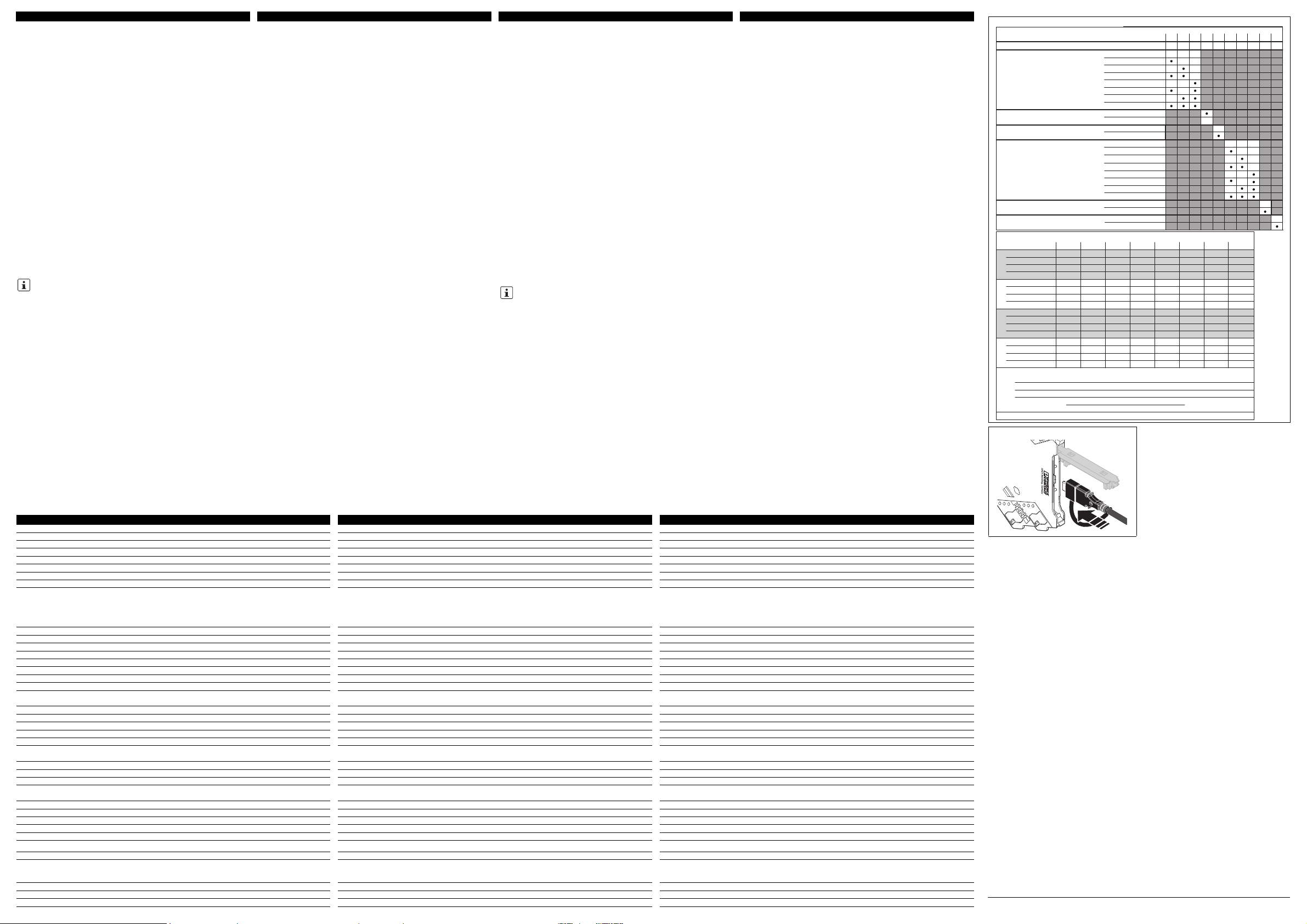
5.1 Configuração por chave DIP ()
No estado de entrega, todas as chaves DIP encontram-se na posição "OFF".
Configure as chaves DIP de acordo com a utilização planejada com auxílio da
tabela ao lado.
5.2 Configuração por software
Além das chaves DIP, a configuração de software oferece opções avançadas de
ajustes e uma função de monitoração.
Duas soluções de software estão disponíveis na Internet para download gratuito.
– Software padrão ANALOG-CONF
– Soluções FTD/DTM: aplicação geral FTD e pacotes DTM
5.3 Configuração via aplicativo MINI Analog Pro ()
Além das chaves DIP, a configuração do aplicativo oferece opções avançadas de
ajustes.
Com o aplicativo para smartphone MINI Analog Pro, é possível configurar o
módulo sem outros adaptadores de configuração pela interface NFC do seu
smartphone, sem uso de cabos.
6. Indicações de diagnóstico e estado
Para a ligação entre dispositivo e PC, use o adaptador de programação IFSUSB-PROG (cód. 2811271) ou o adaptador NFC-USB-PROG-ADAPTER
(cód. ref.: 2900013). ()
LED verde PWR Tensão de alimentação
Acende Alimentação da tensão está presente
LED
vermelho
ERR Indicação de falha ou modo de simulação
Pisca rapidamente
(2,8 Hz)
Erro de de sensor, ou configuração inválida de
chaves DIP.
Pisca rapidamente
(1,4Hz)
Modo de simulação
Acende erro interno do dispositivo.
4.4 Siglatura
Per la siglatura dei dispositivi sono disponibili - anche su richiesta del cliente cartellini di siglatura standard UCT-EM o UC-EMLP. Inoltre i coperchi presentano
sufficiente spazio per l'impiego delle etichette adesive desiderate - ad esempio SK
5,0 WH:REEL - senza coprire l'indicatore LED.
4.5 Monitoraggio degli errori FM
Oltre ai guasti del modulo o nell'alimentazione, vengono segnalati al modulo di
monitoraggio errori a profilo identico MINI MCR-2-FM-RC (codice 2904504) o
MINI MCR-2-FM-RC-PT (codice 2904508) mediante il connettore per guide di
montaggio anche gli errori riconosciuti nell'ingresso di segnalazione del modulo.
Quindi l'errore viene segnalato a livello centrale attraverso un contatto chiuso a
riposo.
Per gli apparecchi collegati è sufficiente un unico modulo di monitoraggio errori.
Non è necessaria una valutazione singola di ognuno degli amplificatori di
isolamento MINI Analog Pro (fino a 115) innestati.
Il comportamento del contatto di monitoraggio errori in funzione delle diverse
configurazioni dei DIP switch è descritto nella tabella corrispondente nella scheda
tecnica presente nel sito phoenixcontact.net/products.
5. Configurazione
L'apparecchio viene fornito con la seguente configurazione standard:
Rilevamento automatico del potenziometro attivato; uscita 4...20mA; sistema di
elaborazione errori a norma NE43 (downscale); il contatto per il monitoraggio degli
errori reagisce a tutti i tipi di errore.
La configurazione è possibile su tutte le varianti di configurazione anche senza
tensione di alimentazione.
Per informazioni dettagliate su tutte le varianti di configurazione, consultare la
scheda tecnica all'indirizzo phoenixcontact.net/products.
5.1 Configurazione tramite DIP switch ()
Al momento della fornitura tutti i DIP switch si trovano nella posizione "OFF".
Configurare i DIP switch in base all'utilizzo previsto con l'aiuto della tabella a
fianco.
5.2 Configurazione tramite software
La configurazione del software offre, oltre all'impostazione dei DIP switch, opzioni
di impostazioni ampliate e una funzione di monitoraggio.
È possibile scaricare gratuitamente da internet due soluzioni software.
– Software standard ANALOG-CONF
– Soluzioni FTD/DTM: frame application FTD e pacchetti DTM
5.3 Configurazione mediante app MINI Analog Pro ()
La configurazione mediante app offre, oltre all'impostazione dei DIP switch,
opzioni di impostazioni ampliate.
Grazie all'app per smartphone MINI Analog Pro è possibile configurare in modalità
wireless il dispositivo mediante l'interfaccia NFC dello smartphone senza l'impiego
di adattatori di programmazione aggiuntivi.
6. Indicatori diagnostici e di stato
Utilizzare l’adattatore per programmazione IFS-USB-PROG-ADAPTER
(codice 2811271) o il NFC-USB-PROG-ADAPTER (codice 2900013) per il
collegamento del dispositivo al PC. ()
LED verde PWR Tensione di alimentazione
Acceso Tensione di alimentazione presente
LED rosso ERR Segnalazione di errore e modalità di simulazione
Lampeggio veloce
(2,8Hz)
Errore sensore o configurazione DIP switch non
valida
Lampeggio lento
(1,4Hz)
Modalità di simulazione
Acceso Errore interno dispositivo
© PHOENIX CONTACT 2013
DNR 83147805 - 02
PNR 105718 - 02
Page 5
PHOENIX CONTACT GmbH & Co. KG
Flachsmarktstraße 8, 32825 Blomberg, Germany
Fax +49-(0)5235-341200, Phone +49-(0)5235-300
MNR 9063889
phoenixcontact.com
MINI MCR-2-POT-UI 2902016
MINI MCR-2-POT-UI-PT 2902017
MINI MCR-2-POT-UI-C 2905005
MINI MCR-2-POT-UI-PT-C 2905006
6
4
7
8
9
10
11
3
12
21
5
PWR+
PWR–
+
+
–
–
passive
IN
OUT
FM
1 5
2 6
8
5
6
Zone 2
Sensor / Field PLC / DCS
3
4
7
S-Port
OUT U, I–
OUT U, I+
PWR+
PWR–
TI+
1
3
IN
IN
IN
2
active
A
D
C
B
E
MINI MCR-2-…
AWG 26-16
0,2-1,5 mm
2
10 mm
A
B
0,5-0,6 Nm
5-7 lb ln
B
A
MINI MCR-2-…-PT
A
AWG 26-12
0,2-2,5 mm
2
10 mm
ES Instrucciones de montaje para el instalador eléctrico
RU Инструкция по установке для электромонтажника
2013-12-11
© PHOENIX CONTACT 2013
DNR 83147805 - 02PNR 105718 - 02
ESPAÑOLESPAÑOLРУССКИЙРУССКИЙ
4. Instalación
El esquema de conjunto muestra la ocupación de los bornes de conexión. ()
El dispositivo puede encajarse en todos los carriles simétricos de 35mm según
EN6071 5. Si se emplea el cone ctor de bus par a carri les ME6,2TBUS-2 (código:
2869728), coloque este primero en el carril simétrico para puentear la
alimentación de tensión. ()
4.1 Conector FASTCON Pro
El dispositivo tiene bornes de conexión enchufables con borne de separación de
medición integrado: bien en variante push-in o en variante de conexión por tornillo.
Los conectores FASTCON Pro pueden conectarse y desconectarse directamente
sin necesidad de herramientas. Con ayuda del tornillo de fijación integrado podrá
separarse cómodamente del módulo el conector o ponerlo en posición de
seccionamiento incluso en estado adosado.
Una codificación cuádruple impide la conexión errónea al módulo.
4.2 Alimentación de tensión
Dispone de las siguientes opciones para alimentar los módulos:
– Directamente mediante los bornes de conexión del módulo, para un consumo
de corriente total de los módulos adosados de hasta 400mA
Recomendamos la conexión previa de un fusible de 630mA (semilento o lento).
– A través de un módulo de alimentación, p.ej. MINI MCR-2-PTB (código
2902066) o MINI MCR-2-PTB-PT (código 2902067)
– A través de una fuente de alimentación de sistemas MINI-SYS-PS-100-240AC/
24DC/1.5 (código 2866983) o MINI-PS-100-240AC/24DC/1.5/EX (código
2866653)
Para dimensionar la alimentación es indispensable seguir las "Instrucciones de
alimentación de MACX y MINI Analog".
4.3 Medición de corriente
El dispositivo permite la medición de corriente sin separar los conductores gracias
a los bornes de separación de medición integrados. ()
Para la medición de corriente use sondas de 2 mm del tipo Fluke TL75-1 o sondas
de forma comparable.
Además podrán seccionarse dirigidamente determinados circuitos de corriente,
p.ej. para las puestas en servicio.
La posición de corte podrá Ud. ajustarla girando 180° el tornillo de fijación
integrado. La posición de corte la señalizan las marcas de los conectores. ()
IMPORTANTE: descarga electrostática
¡Tome medidas de protección contra descargas electrostáticas!
IMPORTANTE
¡Tenga siempre en cuenta el sentido de encaje del módulo MINI
Analog y del conector de carriles simétricos: pie de fijación (D) abajo
y parte enchufable (C) a la izquierda!
IMPORTANTE
¡Nunca conecte la tensión de alimentación directamente al conector
de bus para carril! ¡No está permitida la salida de energía de
dispositivos individuales!
Измерительные преобразователи положения
потенциометра
1. Правила техники безопасности
1.1 инструкции по монтажу
• Устройство категории 3 подходит для установки во взрывоопасной части
зоны 2. Оно соответствует требованиям EN 60079-0:2012 и EN 6007915:2010.
• Монтаж, управление и работы по техобслуживанию разрешается
выполнять только квалифицированным специалистам по
электротехническому оборудованию. Следовать описанным указаниям
по монтажу. При установке и эксплуатации соблюдайте действующие
инструкции и правила техники безопасности (в том числе и национальные
предписания по технике безопасности), а также общетехнические
правила. Сведения о безопасности содержатся в данной инструкции и
сертификатах (сертификат об оценке соответствия, при необходимости
дополнительные сертификаты).
• При работе устройств на элементах управления могут возникнуть
опасные напряжения. Поэтому настройку параметров, подключение
проводов или открытие крышки модуля выполнять только в обесточенном
состоянии, при условии, что подключенные цепи не представляют собой
исключительно цепи БСНН или ЗСНН.
• Запрещается открывать или модифицировать устройство. Не
ремонтируйте устройство самостоятельно, а замените его на
равноценное устройство. Ремонт должен производиться только
сотрудниками компании-изготовителя. Производитель не несет
ответственности за повреждения вследствие несоблюдения
предписаний.
• Степень защиты IP20 (IEC 60529/EN 60529) устройства предусматривает
использование в условиях чистой и сухой среды. Не подвергайте
устройство механическим и/или термическим нагрузкам, превышающим
указанные предельные значения.
• Устройство не предназначено для применения во взрывоопасной по пыли
атмосфере.
• Устройство отвечает директивам в отношении подавления радиопомех
(ЭМС) при использовании в промышленных помещениях (класс
подавления радиопомехА). При использовании в жилых помещениях
устройство может вызвать нежелательные радиопомехи.
• Если устройство используется не в соответствии с документацией, это
может повлиять на защиту, предусмотренную в устройстве.
• Устройство для защиты от механических или электрических повреждений
встроить в соответствующий корпус с необходимой степенью защиты
согласно МЭК60529.
• Поблизости от устройства должен быть предусмотрен переключатель или
силовой выключатель, маркированный как отсекающее устройство для
данного устройства.
• Предусмотрите в схеме устройство защиты от токов перегрузки (I ≤ 4 A).
• Благодаря наличию корпуса устройство изолировано от соседних
устройств, расчитанных на 150Вэфф. Это необходимо учитывать при
монтаже нескольких устройств, расположенных рядом друг с другом. При
необходимости следует установить дополнительную изоляцию!
• Напряжения на входе, выходе и в цепи питания являются сверхнизкими
напряжениями (ELV – Extra-Low-Voltage). В зависимости от конкретных
условий применения может появиться опасное напряжение относительно
земли (>30В). Для этого случая имеется надежная гальваническая
развязка с другими подключениями.
• В случае повреждения, неправильной нагрузки или хранения или
ненадлежащей работы устройства, оно должно быть изъято из
эксплуатации.
1.2 Установка в зоне 2
• Соблюдать установленные правила применения во взрывоопасных зонах!
При установке использовать только соответствующий допущенный к
применению корпус (минимальная степень защиты IP54), отвечающий
требованиям стандарта EN 60079-15. При этом соблюдать требования
стандарта EN 60079-14.
• К цепям питания в зоне 2 могут быть подключены только устройства,
предназначенные для работы во взрывоопасной зоне 2 и
соответствующие условиям по месту применения.
• Установка на монтажную рейку и демонтаж с нее, а также подключение и
отключение проводов во взрывоопасной области должны производиться
только в условиях отключенного электропитания.
• В случае повреждения, неправильной установки, неверного
функционирования устройства или воздействия на него ненадлежащей
нагрузки, следует немедленно отключить его и вывести за пределы
взрывоопасной зоны.
2. Краткое описание
Конфигурируемый, 3-хканальный развязанный потенциометрический
измерительный преобразователь со штекерными разъемами.
Показатели измерений преобразуются в линейный и свободно
настраиваемый сигнал тока или напряжения.
Устройство может конфигурироваться на выбор с помощью DIPпереключателей или с расширенной функциональностью через S-порт с
помощью стандартного ПО Analog-Conf, посредством FDT/DTM или без
дополнительных принадлежностей при помощи MINI Analog Pro Smartphone
App.
Если невозможно полностью исчерпать диапазон регулировки
потенциометра, то можно задать верхние и нижние его значения в самом
ПО.
Устройство поддерживает мониторинг ошибок.
Актуальную документацию можно скачать с сайта
phoenixcontact.com.
Это устройство поддерживает связь NFC.
Приложение для смартфона MINI Analog Pro позволяет
конфигурировать устройство посредством NFC-интерфейса Вашего
смартфона, получать помощь по настройке DIP-переключателями и
обширную информацию по модулям.
Приложение App для смартфона MINI Analog Pro предоставляется
бесплатно. ()
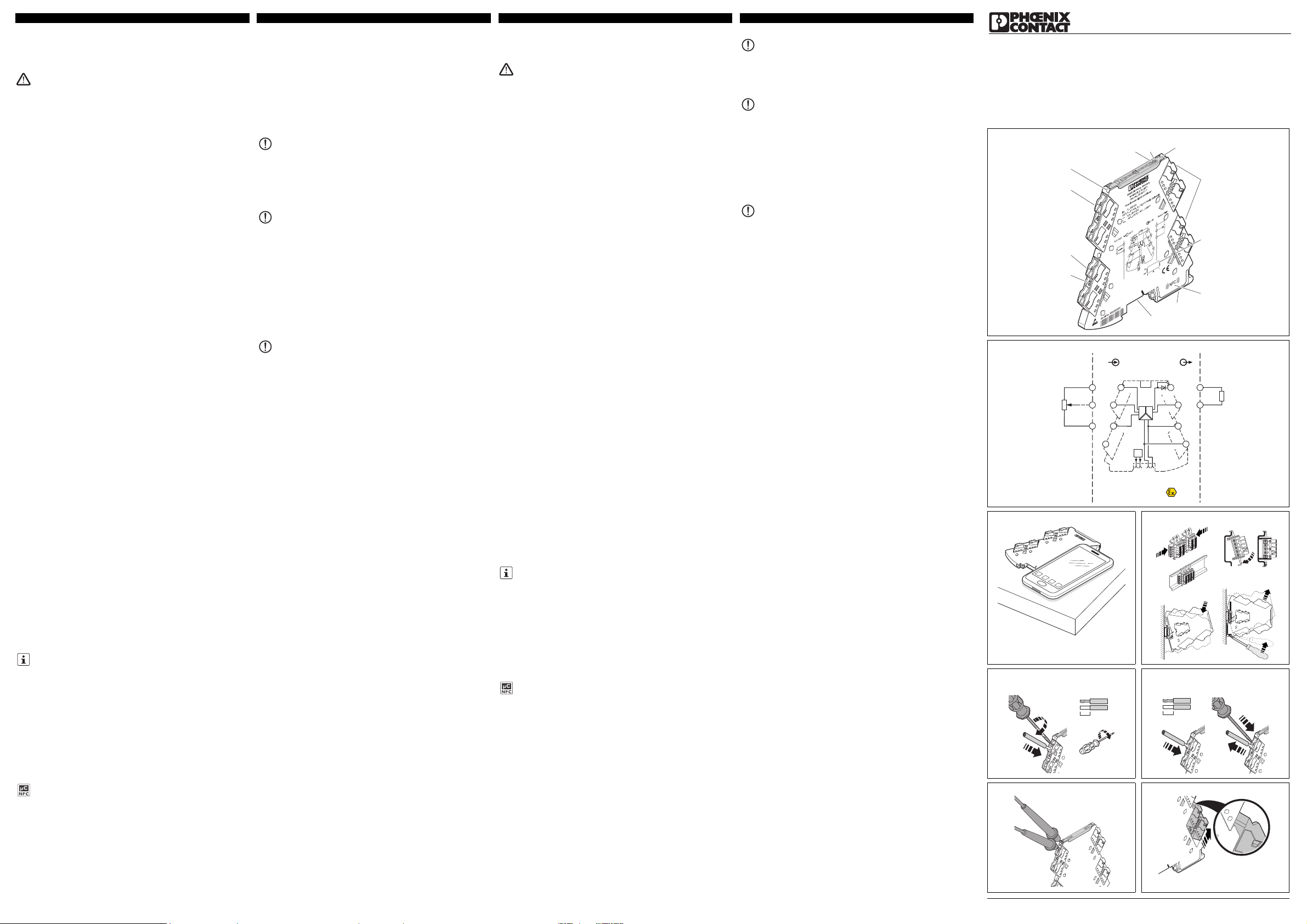
3. Элементы управления и индикации ()
4. Монтаж
На блок-схеме показано назначение выводов клемм. ()
Устройство устанавливается на защелках на монтажные рейки шириной 35
мм любого типа согласно EN60715. Используя устанавливаемый на
монтажную рейку соединитель ME6,2TBUS-2 (арт. №: 2869728), для
разветвления цепей питания сначала устанавливаются эти соединители.
()
4.1 FASTCON Pro, штекер
Устройство оснащено вставными соединительными клеммами с
интегрированной измерительной разделительной клеммой по выбору с
вставными или резьбовыми разъемами.
Штекеры FASTCON Pro можно напрямую вставлять или отсоединять без
использования инструментов. При помощи встроенного крепежного винта
установленные в ряд штекеры также можно удобно отсоединять от модуля
или устанавливать в позицию разделения.
4-кратная кодировка предотвращает неправильное подсоединение на
модуле.
4.2 Питающее напряжение
У Вас есть следующие возможности запитать модули:
– Напрямую через соединительные клеммы модуля, при суммарном
потребляемом токе установленных в ряд модулей до 400мА
Рекомендуется на входе ставить предохранитель на 630мА (полуинертного
или инертного типа).
– Через клемму питания (например, MINI MCR-2-PTB, арт. №: 2902066 или
MINI MCR-2-PTB-PT, арт. №: 2902067)
– Через блок питания MINI-SYS-PS-100-240AC/24DC/1.5 (арт. №: 2866983)
или MINI-PS-100-240AC/24DC/1.5/EX (арт. №: 2866653)
При выборе подачи питания обязательно см. "Инструкцию по подаче
питания MACX и MINI Analog".
4.3 Измерения сигнала тока
Прибор позволяет производить измерение тока без разъединения
проводников при помощи интегрированных измерительных
разделительных клемм. ()
Используйте для измерения тока 2-мм измерительные наконечники типа
Fluke TL75-1 или измерительные наконечники с аналогичной формой.
Помимо этого возможно выделение отдельных электроцепей, например,
при пусках в эксплуатацию.
Позиция разделения может настраиваться посредством поворота
интегрированного крепежного винта на 180°. Позиция разделения
показывается маркировкой на штекерах. ()
1 Красный светодиод "ERR",
индикатор сбоя
7 Универсальное монтажное
основание с защелками, рейки
EN-типа
2 Зеленый светодиод "PWR",
питание
8 Подключение соединителя для
монтажной рейки
3 Крышка с возможностью
маркировки
9 Крепежный винт
4 Вход: Потенциометр 10 Электропитание
5 DIP-переключатель S1 11 Выход: Нормированные сигналы
6 Катушка NFC 12 Гнездо измерения тока
ВНИМАНИЕ: Электростатический разряд
Должны быть предприняты меры по защите от электростатических
разрядов!
ПРЕДУПРЕЖДЕНИЕ
Обязательно соблюдать направление фиксации защелками
аналогового модуля MINI и устанавливаемого на монтажную
рейку соединителя: монтажное основание с защелками (D)
внизу, а штекерная часть (C) слева!
ПРЕДУПРЕЖДЕНИЕ
Никогда не подключайте напряжение питания непосредственно
к шинному коммутатору BUS! Отбор энергии из отдельных
устройств недопустим!
Convertidores de posición de potenciómetro
1. Advertencias de seguridad
1.1 Indicaciones de instalación
• El aparato de la categoría 3 es apto para la instalación en áreas expuestas a
riesgo de explosión de la zona 2. Cumple con las exigencias de EN 600790:2012 y EN 60079-15:2010.
• La instalación, el manejo y el mantenimiento deben ser ejecutados por personal
especializado, cualificado en electrotecnia. Siga las instrucciones de instalación
descritas. Para la instalación y el manejo, cumpla las disposiciones y normas de
seguridad vigentes (también las normas de seguridad nacionales), así como las
reglas generales de la técnica. Encontrará los datos técnicos de seguridad en
este prospecto y en los certificados (evaluación de conformidad y otras
aprobaciones, en caso necesario).
• Durante el funcionamiento de los dispositivos puede haber tensiones peligrosas
al contacto físico en los elementos de mando. Por tanto, la parametrización, la
conexión de cables o la apertura de la tapa del módulo se permiten solamente
en estado libre de tensión, salvo que los circuitos conectados sean
exclusivamente circuitos de baja tensión de seguridad (SELV o PELV).
• No está permitido abrir o realizar modificaciones en el aparato. No repare el
equipo usted mismo, sustitúyalo por otro de características similares. Sólo los
fabricantes deben realizar las reparaciones. El fabricante no se hace
responsable de los daños derivados del incumplimiento de estas
prescripciones.
• El tipo de protección IP20 (IEC 60529/EN 60529) del equipo está previsto para
un entorno limpio y seco. Detenga el equipo ante cargas mecánicas y/o térmicas
que superen los límites descritos.
• El equipo no está diseñado para la inserción en atmósferas expuestas a peligro
de explosión por polvo.
• El dispositivo cumple la normativa de protección electromagnética (CEM) para
el área industrial (protección electromagnética: claseA). Si se emplea en
ambientes domésticos, puede producir interferencias electromagnéticas.
• Si el dispositivo no se usa tal y como se indica en su documentación, es posible
que la protección provista se vea negativamente afectada.
• Para salvaguardar el dispositivo contra daños mecánicos o eléctricos, móntelo
en una carcasa que tenga el grado de protección necesario conforme a IEC
60529.
• Disponga cerca del aparato un interruptor/interruptor de potencia que esté
marcado como dispositivo separador para este equipo.
• Disponga un dispositivo de protección contra sobrecorriente (I ≤ 4 A) en la
instalación.
• Gracias a su carcasa, el dispositivo dispone respecto a los dispositivos
adyacentes de un aislamiento básico para 150Veff. Si se instalan varios
dispositivos contiguamente, habrá que tener esto en cuenta y, de ser necesario,
montar un aislamiento adicional.
• Las tensiones que hay en la entrada, la salida y la alimentación son tensiones
extra bajas ELV (Extra-Low-Voltage). Según el uso dado, es posible que haya
tensión peligrosa (>30V) respecto a tierra. Para tales casos se ha provisto una
separación galvánica segura frente a las demás conexiones.
• Habrá que poner el dispositivo fuera de servicio si está dañado, se ha cargado
o guardado inadecuadamente o funciona incorrectamente.
1.2 Instalación en la zona 2
• Cumpla las condiciones fijadas para el montaje en áreas expuestas a peligro de
explosión. Durante la instalación utilice una carcasa autorizada adecuada (tipo
de protección mínima IP54) que cumpla con los requisitos de la EN 60079-15.
Observe también los requerimientos de EN 60079-14.
• En circuitos de corriente de la zona 2 solo se deben conectar equipos aptos para
el funcionamiento en la zona Ex 2 y para las condiciones del lugar de montaje.
• Sólo se permite encajar o extraer el conector para carriles de carga o conectar
y separar conductores en el área de peligro de explosión cuando se encuentra
en estado sin tensión.
• Debe desconectarse el equipo y retirarlo inmediatamente de la zona Ex si está
dañado o se ha cargado o guardado de forma inadecuada o funciona
incorrectamente.
2. Descripción resumida
Convertidor de potenciómetro configurable con separación de 3 vías en técnica de
conexión insertable.
Los valores medidos se convierten en una señal lineal de corriente o de tensión
libremente ajustable.
Usted podrá configurar el dispositivo bien mediante los microinterruptores DIP o
bien con funcionalidad ampliada mediante el puerto S del software estándar
Analog-Conf a través de FDT/DTM o bien sin necesidad de más accesorios
mediante el App MINI Analog Pro Smartphone.
Si no es posible aprovechar todo el rango posible del potenciómetro, podrá Ud.
definir los valores superior e inferior del potenciómetro en el software.
El dispositivo es compatible con la monitorización de errores (Fault Monitoring).
3. Elementos de operación y de indicación ()
Puede descargar la documentación actual en la dirección
phoenixcontact.com.
Este dispositivo ofrece la posibilidad de comunicación por NFC.
El App MINI Analog Pro Smartphone le permitirá acceder a través de la
interfaz NFC de su Smartphone a extensa información del módulo y a un
auxiliar de configuración de microinterruptores DIP para configurar el
dispositivo.
El App MINI Analog Pro Smartphone podrá obtenerlo gratuitamente. ()
1 LED rojo de errores "ERR" 7 Pie de encaje universal para carriles
simétricos EN
2 LED verde "PWR", alimentación de
tensión
8 Conexión para conector para
carriles
3 Tapa con posibilidad de rotulación 9 Tornillo de fijación
4 Entrada: potenciómetro 10 Tensión de alimentación
5 Interruptor DIP S1 11 Salida: señales normalizadas
6 Bobina NFC 12 Conector hembra amperimétrico
Page 6
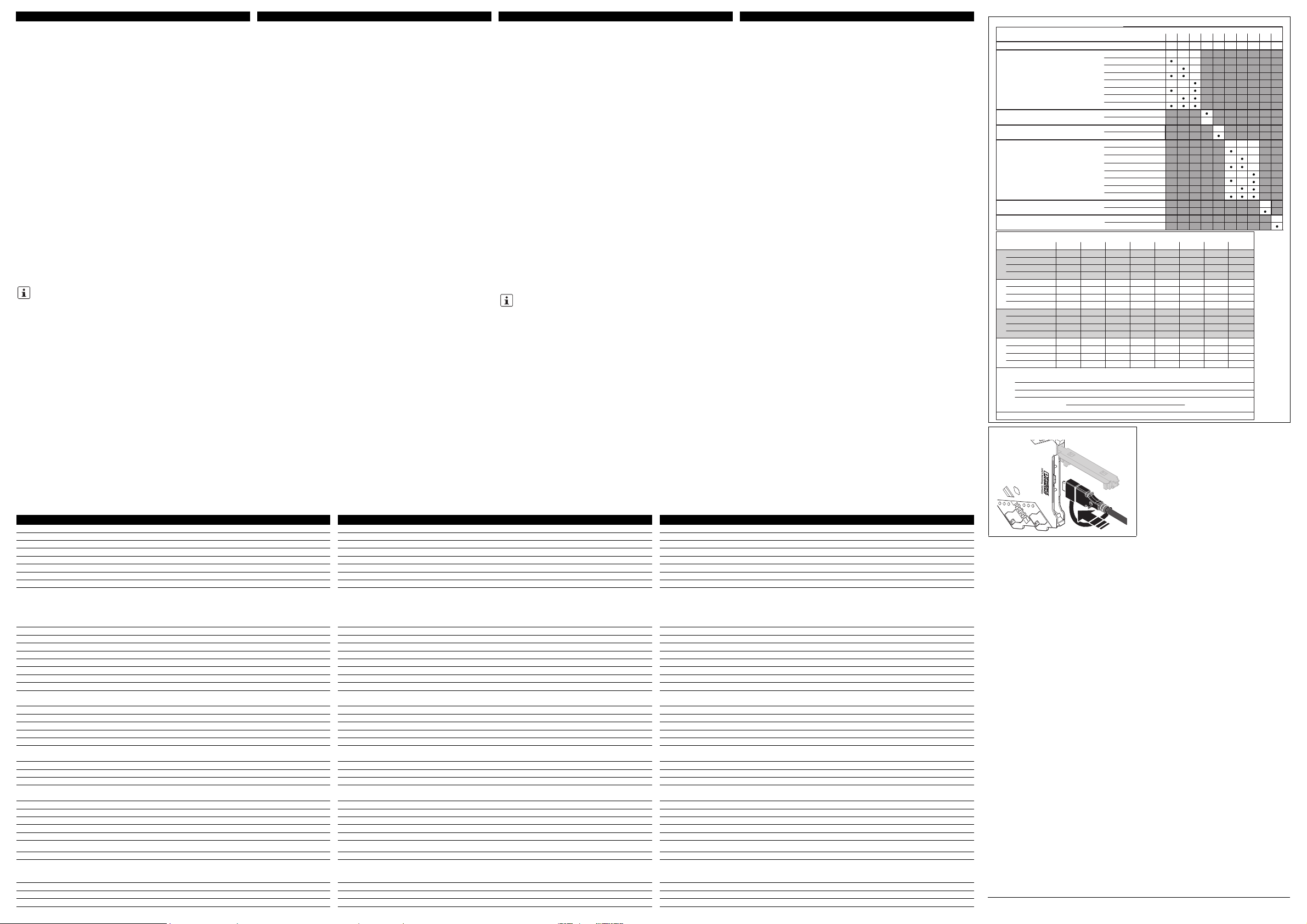
98
DIP S1
1230456
0...20 mA
20...4 mA
OFF
A
B
C
D
NE43 upscale
NE43 downscale
NE43 0 mA
NE43 up-/downscale
OFF
OFF
ON
ON
ON
Line break dectection
Error
OUT
Automatic potentiometer detection
DIP config
Software/App config
Average
Default
0...10 V
10...0 V
4...20 mA
0...5 V
1...5 V
7
20...0 mA
0...20 mA
Line-break slider
21 mA
A
B
C
D
Line-break ,slider overrange, underrange, line-break pot
NE43
Error evaluation - Analog OUT
Upscale
Downscale
0mA
Up-/Downscale
= 21.5 mA
Line-break ,slider overrange, underrange, line-break pot
Line-break ,slider overrange, underrange ,line-break pot
Line-break slider
, line-break pot
3.5 mA
0mA
3.5 mA
= 21.5 mA
=
=
=
Overrange, underrange
Overrange and underrange signalisation only possible with Software/App configuration
Overrange
Underrange
20...0 mA 4...20 mA 20...4 mA
0...10 V 10...0 V 0...5 V 1...5 V
20.5 mA
0mA
21 mA
20.5 mA
0mA
21 mA
20.5 mA
4mA
21 mA
20.5 mA
4mA
10.5 V
10.25 V
0V
10.5 V
10.25 V
0V
5.25 V
5.125 V
0V
5.25 V
5.125 V
1V
Line-break slider
21 mA
Overrange
Underrange
20.5 mA
0mA
21 mA
20.5 mA
0mA
21 mA
20.5 mA
3.5 mA
21 mA
20.5 mA
3.5 mA
10.5 V
10.25 V
0V
10.5 V
10.25 V
0V
5.25 V
5.125 V
0V
5.25 V
5.125 V
0.875 V
Line-break slider
21 mA
Overrange
Underrange
20 mA
0mA
21 mA
20 mA
0mA
21 mA
20 mA
4mA
21 mA
20 mA
4mA
10.5 V
10 V
0V
10.5 V
10 V
0V
5.25 V
5V
0V
5.25 V
5V
1V
Line-break slider
0mA
Overrange
Underrange
20 mA
0mA
0mA
20 mA
0mA
4mA
20 mA
4mA
4mA
20 mA
4mA
0V
10 V
0V
0V
10 V
0V
0V
5V
0V
1V
5V
1V
(only OUT = 4...20 mA or 20...4 mA)
Line-break pot
0mA 0mA 4mA 4mA 0V 0V 0V 1V
Line-break pot
0 mA 0 mA 3 mA 3 mA 0 V 0 V 0 V 0.75 V
Line-break pot
21 mA 21 mA 21 mA 21 mA 10.5 V 10.5 V 5.25 V 5.25 V
Line-break pot
0mA 0mA 4mA 4mA 0V 0V 0V 1V
ESPAÑOLESPAÑOLРУССКИЙРУССКИЙ
Технические характеристики Datos técnicos
Тип подключения Tipo de conexión
Винтовые зажимы Conexión por tornillo MINI MCR-2-POT-UI 2902016
Винтовые зажимы Conexión por tornillo MINI MCR-2-POT-UI-C 2905005
Зажимы Push-in Conexión "Push-in" MINI MCR-2-POT-UI-PT 2902017
Зажимы Push-in Conexión "Push-in" MINI MCR-2-POT-UI-PT-C 2905006
Входные данные Datos de entrada
Потенциометр мин./макс. Potenciómetro mín./máx. 0 ... 100 Ω / 0 ... 100 kΩ
Выходные данные Datos de salida I U
Выходной сигнал настраивается DIP-переключателем Señal de salida mediante selector DIP 0 mA ... 20 mA 1 V ... 5 V
настраивается DIP-переключателем mediante selector DIP 4 mA ... 20 mA 10 V ... 0 V
настраивается DIP-переключателем mediante selector DIP 20 mA ... 0 mA 0 V ... 5 V
настраивается DIP-переключателем mediante selector DIP 20 mA ... 4 mA 0 V ... 10 V
настраивается с помощью ПО Ajustable a través de software 0 mA ... 21 mA 0 V ... 10,5 V
Максимальный выходной сигнал Señal máxima de salida 24,6 mA aprox. 12,3 V
Нагрузка R
B
Carga R
B
≤ 600 Ω ≥ 10 kΩ
Ток короткого замыкания Corriente de cortocircuito - < 31,5 mA
Напряжение без нагрузки Tensión en circuito abierto < 17,5 V Пульсации Ripple < 20 mV
PP
Общие характеристики Datos generales
Напряжение питания U
B
Tensión de alimentación U
B
24 V DC
Напряжение питания U
B
Tensión de alimentación U
B
9,6 V DC ... 30 V DC
Потребляемый ток при 24 В DC Absorción de corriente con 24 V DC 30 mA
при 12 В постоян. тока con 12 V DC 63 mA
Потребляемая мощность при I
OUT
= 20 мА, 9,6 В пост. тока, 600 Ом нагрузка Consumo de potencia con I
OUT
= 20 mA, 9,6 V DC, carga de 600 Ω≤ 750 mW
Ошибка передачи, макс. R < 240 Ω = < 0,2 % Error de transmisión máximo R < 240 Ω = < 0,2 % < 0,1 %
Температурный коэффициент, максимальный Coeficiente de temperatura máximo 0,01 %/K
Ступенчатая характеристика (10-90%) Respuesta gradual (10-90%) < 60 ms
Степень защиты Índice de protección IP20
Диапазон рабочих температур Эксплуатация Margen de temperatura ambiente Funcionamiento -40 °C ... 70 °C
Хранение/транспортировка Almacenamiento/transporte -40 °C ... 85 °C
Отн. влажность воздуха без выпадения конденсата Humedad del aire sin condensación 5 % ... 95 %
Материал корпуса Material de la carcasa PBT
Размеры Ш / В / Г Dimensiones An. / Al. / Pr. 6,2 mm / 110,5 mm / 120,5 mm
Гальваническая развязка Separación galvánica
Усиленная изоляция согласно МЭК 61010-1 Aislamiento reforzado según IEC 61010-1
Категория перенапряжения Categoría de sobretensiones II
Степень загрязнения Grado de polución 2
Расчетное напряжение изоляции Tensión de aislamiento de dimensionamiento 300 V
Испытательное напряжение, вход / выход / питание Tensión de prueba Entrada/salida/alimentación 3 kV (50 Hz, 1 min)
Соответствие нормам /допуски Соответствие CE Conformidad / Homologaciones Conformidad CE
ATEX ATEX
II 3 G Ex nA IIC T4 Gc X
Судостроение На рассмотрении GL Construcción de navíos GL solicitada
UL, США / Канада
508 Listed на рассмотрении
Class I, Div. 2, Groups A, B, C, D T5 на рассмотрении
UL, EE.UU. / Canadá
508 Listed solicitado
Class I, Div. 2, Groups A, B, C, D T5 solicitado
Соответствует Директиве по ЭМС 2004/108/EG Conformidad con la directiva CEM 2004/108/CE
Излучение помех согласно Emisión de interferencias según EN 61000-6-4
Помехоустойчивость В случае электромагнитных помех возможны незначительные отклонения. Resistencia a interferencias Durante las interferencias pueden producirse ligeras desviaciones. EN 61000-6-2
4.4 Маркировочные принадлежности
Для нанесения надписей на устройства (также по желанию заказчика)
имеются стандартные маркировочные таблички UCT-EM... или UC-EMLP....
Кроме того, на крышке имеется достаточно места для использования любых
клеящихся этикеток, например, SK 5,0 WH:REEL, не закрывая при этом
светодиодные диагностические индикаторы.
4.5 Мониторинг ошибок FM
По шинному коммутатору BUS на модуль мониторинга сбоев MINI MCR-2FM-RC (Арт. №: 2904504) или MINI MCR-2-FM-RC-PT (Арт. №: 2904508) того
же контура сигнализируются помимо выхода модуля из строя или обрыва
питания также распознанные сбои на сигнальном входе модуля. Сообщение
сбоя происходит централизованно через размыкающий контакт.
Модуль мониторинга ошибок в группе требуется только один раз. Отпадает
необходимость индивидуального анализа установленных разделительных
усилителей MINI Analog Pro (до 115 шт.).
Поведение контакта мониторинга сбоев при различных конфигурациях DIPпереключателей см. в соответствующей таблице в техническом описании по
адресу phoenixcontact.net/products.
5. Конфигурация
Устройство поставляется в следующей стандартной конфигурации:
Включено автоматическое распознавание потенциометра; выход 4...20мА;
анализ сбоев согласно NE43 (downscale); контакт диагностики сбоев
срабатывает при всех сбоях.
Конфигурация возможна во всех вариантах конфигурации без
подключенного питающего напряжения.
Детальная информация по всем вариантам конфигурации содержится в
техническом описании по адресу phoenixcontact.net/products.
5.1 Конфигурация с помощью DIP-переключателя ()
После поставки все DIP-переключатели находятся в положении "ВЫКЛ".
Настройте DIP-переключатели в соответствии с предполагаемыми
условиями применения, руководствуясь расположенной рядом таблицей.
5.2 Конфигурация с помощью ПО
Программная конфигурация предоставляет в отличие от настройки
посредством DIP-переключателей расширенные возможности настройки и
функцию мониторинга.
В интернете для бесплатного скачивания подготовлено два ПО.
– Стандартное ПО ANALOG-CONF
– Решения FTD/DTM: рамочное приложение FTD и пакеты DTM
5.3 Конфигурация при помощи приложения для смартфона MINI
Analog Pro ()
Конфигурация при помощи приложения для смартфона предоставляет в
отличие от настройки посредством DIP-переключателей расширенные
возможности настройки.
Приложение для смартфона MINI Analog Pro позволяет конфигурировать
модуль без дополнительных адаптеров для программирования и кабеля
посредством NFC-интерфейса Вашего смартфона.
Для подключения устройства к ПК используйте адаптер для
программирования IFS-USB-PROG-ADAPTER (Арт. №: 2811271) или
NFC-USB-PROG-ADAPTER (Арт. №.: 2900013). ()
6. Индикаторы диагностики и индикаторы состояния
Зеленый
светодиод
PWR Электропитание
Горит Питающее напряжение приложено
Красный
светодиод
ERR Индикация сбоев или режим симуляции
Мигает быстро
(2,8 Гц)
Сбой датчика или недействительная
конфигурация DIP-переключателей
Мигает медленно
(1,4Гц)
Режим симуляции
Горит Внутренняя ошибка устройства
4.4 Rotulación
Para la rotulación de los dispositivos se dispone (también bajo pedido del cliente)
de plaquitas de rotulación impresas estándar UCT-EM... o UC-EMLP.... Además,
las tapas ofrecen suficiente espacio para la utilización de cualquier etiqueta
autoadhesiva, como p.ej. SK 5,0 WH:REEL, sin que ello obstaculice la visión a los
LEDs de diagnóstico.
4.5 Monitorización de errores FM
Además de un corte de corriente o el cese del funcionamiento del módulo,
también los errores detectados en la entrada de señal del módulo se comunican a
tra vés del c one ctor de b us pa ra c arri l al módu lo F ault -Mon ito rin g MIN I MC R-2- FMRC (código 2904504) o MINI MCR-2-FM-RC-PT (código 2904508). Este transmite
el error a nivel central a través de un contacto normalmente cerrado (NC).
Se nec esita un so lo módulo F ault-Monit oring en el sistema. E llo hace in necesaria
la evaluación individual de hasta 115 amplificadores de separación MINI Analog
Pro adosados.
Consulte el comportamiento del contacto de monitorización de fallos según las
distintas configuraciones de microinterruptores DIP en la respectiva tabla de la
hoja de características disponible en phoenixcontact.net/products.
5. Configuración
El dispositivo se expide con la siguiente configuración predeterminada:
Detección automática del potenciómetro activada; salida de 4...20mA; evaluación
de errores según NE43 (downscale); el contacto de monitorización de fallos
reacciona frente a todos los errores.
En todas las variantes es posible realizar la configuración sin tensión de
alimentación.
Encontrará información más detallada sobre todas las variantes de configuración
en la hoja de características disponible en phoenixcontact.net/products.
5.1 Configuración mediante interruptores DIP ()
En estado de suministro, todos los interruptores DIP se encuentran en posición
"OFF".
Configure el interruptor DIP según la aplicación planeada con la ayuda de la tabla
que aparece al lado.
5.2 Configuración por software
La configuración de software ofrece opciones que van más allá del ajuste por
microinterruptores DIP y una función de monitorización.
Usted dispone de dos soluciones de software gratuitas listas para descargar vía
internet.
– Software estándar ANALOG-CONF
– Soluciones FTD/DTM: aplicación marco FTD y paquetes DTM
5.3 Configuración mediante App MINI Analog Pro ()
La configuración por medio del App ofrece opciones que van más allá del ajuste
por microinterruptores DIP.
El App MINI Analog Pro Smartphone le permitirá configurar el módulo a través de
la interfaz NFC de su Smartphone de forma inalámbrica y sin necesidad de
adaptadores de programación adicionales.
6. Indicaciones de diagnóstico y estado
Utilice el adaptador de programación IFS-USB-PROG-ADAPTER (código
2811271) o NFC-USB-PROG-ADAPTER (código 2900013) para conectar
el dispositivo y el PC. ()
LED verde PWR Tensión de alimentación
Encendido Hay tensión de alimentación
LED rojo ERR Indicador de errores o modo de simulación
Parpadeo rápido
(2,8Hz)
Error de sensor o configuración no válida de
microinterruptores DIP
Parpadeo lento
(1,4Hz)
Modo de simulación
Encendido error interno del dispositivo
© PHOENIX CONTACT 2013
DNR 83147805 - 02
PNR 105718 - 02
Page 7
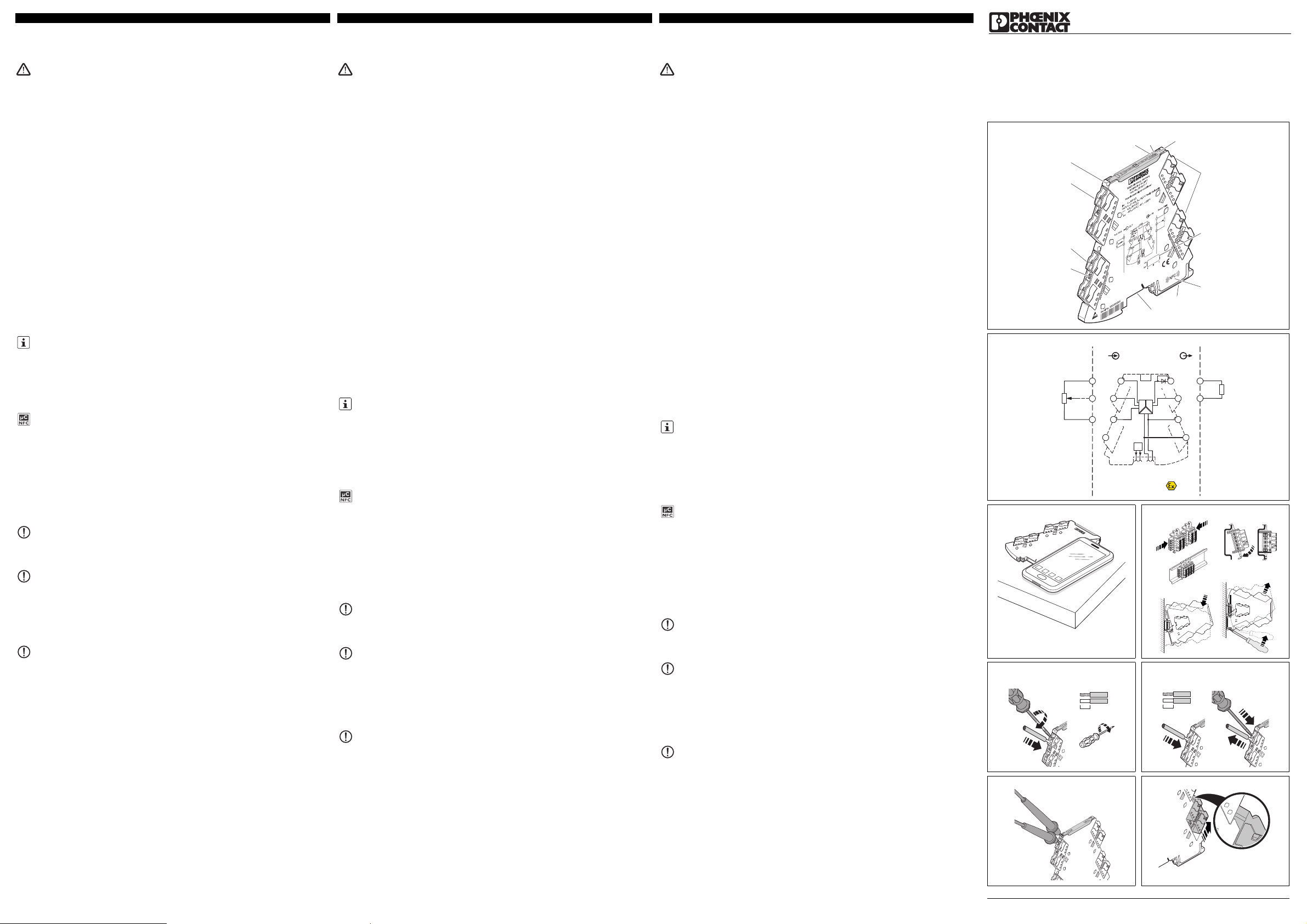
PHOENIX CONTACT GmbH & Co. KG
Flachsmarktstraße 8, 32825 Blomberg, Germany
Fax +49-(0)5235-341200, Phone +49-(0)5235-300
phoenixcontact.com
EN Installation notes for electricians
TR Elektrik personeli için montaj talimatı
ZH 电气人员安装须知
2013-12-11
© PHOENIX CONTACT 2013
Potiposition transducer
1. Safety notes
1.1 Installation notes
• The category 3 device is suitable for installation in potentially explosive area zone 2. It fulfills the requirements
of EN 60079-0:2012 and EN 60079-15:2010.
• Installation, operation, and maintenance may only be carried out by qualified electricians. Follow the
installation instructions as described. When installing and operating the device, the applicable regulations
and safety directives (including national safety directives), as well as generally approved technical
regulations, must be observed. The safety data is provided in this package slip and on the certificates
(conformity assessment, additional approvals where applicable).
• While the devices are in operation, contact-dangerous volt ages may be present on the control elements. For
this reason parameterization, conductor connection, and opening of the module lid are allowed only when
devices are in a de-energized state unless the connected circuits are exclusively SELV or PELV circuits.
• The device must not be opened or modified. Do not repair the device yourself, replace it with an equivalent
device. Repairs may only be carried out by the manufacturer. The manufacturer is not liable for damage
resulting from violation.
• The IP20 protection (IEC 60529/EN 60529) of the device is intended for use in a clean and dry environment.
The device must not be subject to mechanical strain and/or thermal loads, which exceed the limits described.
• The device is not designed for use in atmospheres with a danger of dust explosions.
• The device complies with the EMC regulations for industrial areas (EMC classA). When using the device in
residential areas, it may cause radio interference.
• If the device is not used as described in th e documentation, the intended protection can be negatively affected.
• To protect the device against mechanical or electrical damage, install it in a suitable housing with appropriate
degree of protection according to IEC 60529.
• Provide a switch/circuit breaker close to the device, which is labeled as the disconnecting device for this device.
• Provide for a overcurrent protection device (I ≤ 4 A) in the installation.
• Thanks to its housing, the device has basic insulation to the neighboring devices, for 150Veff. If several
devices are installed next to each other, this has to be taken into account, and additional insulation has to be
installed if necessary!
• The voltages present at the input, output and supply are extra-low voltages (ELV). Depending on the
application, dangerous voltage (>30V) against ground could occur. For this event, safe electrical isolation
from the other connections has been implemented.
• The device must be stopped if it is damaged, has been subjected to an impermissible load, stored incorrectly,
or if it malfunctions.
1.2 Installation in Zone 2
• Observe the specified conditions for use in potentially explosive areas! Install the device in a suitable
approved housing with a minimum of IP54 protection) that meets the requirements of EN 60079-15. Observe
the requirements of EN 60079-14.
• Only devices which are designed for operation in Ex zone 2 and are suitable for the conditions at the
installation location may be connected to the circuits in the Ex zone.
• In potentially explosive areas, terminals may only be snapped onto or off the DIN rail connector and wires
may only be connected or disconnected when the power is switched off.
• The device must be stopped and immediately removed from the Ex area if it is damaged, was subject to an
impermissible load, stored incorrectly or if it malfunctions.
2. Short description
Configurable, 3-way isolated potentiometer measuring transducer with pluggable connection technology.
The measured values are converted into a linear and freely configurable current or voltage signal.
You can optionally configure the device using DIP switches, or with enhanced functionality via the S port using the
standard Analog-Conf software via FDT/DTM, or without further accessories using the Mini Analog Pro Smartphone app.
If utilizing the full potentiometer range is not possible, you can set the upper and lower potentiometer values in
the software.
The device supports fault monitoring.
3. Operating and indicating elements ()
4. Installation
The assignment of the connection terminal blocks is shown in the block diagram. ()
The device can be snapped onto all 35 mm DIN rails according to EN60715. When using the ME6,2TBUS-2
DIN rail connector (Order No. 2869728), first position it in the DIN rail to bridge the voltage supply. ()
4.1 FASTCON Pro plugs
The device has pluggable connection terminals with an integrated test disconnect terminal block, with either
push-in or screw-in connection technology.
You can plug or screw the FASTCON Pro plugs onto the device directly without tools. You can use the integrated fixing
screw to easily remove the plugs from the module or set the isolating position, even when the plugs are connected.
4-way coding prevents incorrect insertion into the module.
4.2 Power supply
The following supply options are available for the module:
– Directly via the connection terminals of the module, with an current consumption of the connected modules
of up to 400mA
We recommend connecting a 630 mA fuse (normal-blow or slow-blow) upstream.
– Via a power terminal (e.g. MINI MCR-2-PTB, order number 2902066, or MINI MCR-2-PTB-PT, order number
2902067)
– Via a MINI-SYS-PS-100-240AC/24DC/1.5 (order number 2866983) or MINI-PS-100-240AC/24DC/1.5/EX
(order number 2866653) system power supply
You must refer to the MACX and MINI Analog power manual for the design of the power supply.
4.3 Current measurement
The device allows current measurement without disconnection of the conductors by means of integrated test
disconnect terminals. ()
For the current measurement, use 2 mm probe tips of the type Fluke TL75-1 or probe tips with a comparable
tip shape.
Furthermore, individual circuits can be specifically disconnected, e.g. for commissioning.
You can set the isolating position by turning the integrated fixing screw through 180°. The isolating position is
indicated by the marking on the plugs. ()
You can download the latest documents from phoenixcontact.com.
This device offers the option of NFC communication.
You can use the MINI Analog Pro Smartphone app via the NFC interface of your Smartphone to
configure the device and to call-up DIP switch setting help and comprehensive module information.
The MINI Analog Pro Smartphone app is available to you free. ()
1 Error indicator "ERR" red LED 7 Universal snap-on foot EN DIN rails
2 Green "PWR" LED, power supply 8 Connection for DIN rail connector
3 Cover with labeling option 9 Mounting screw
4 Input: Potentiometer 10 Supply voltage
5 DIP switch S1 11 Output: Standard signals
6 NFC coil 12 Current measuring socket
NOTE: Electrostatic discharge
Take protective measures against electrostatic discharge.
NOTE
It is essential to observe the snap-in direction of the MINI analog module and DIN rail
connector: Snap-on foot (D) below and plug component (C) left!
NOTE
Never connect the supply voltage directly to the DIN rail connector. Drawing power from
individual devices is not permitted!.
位置变送器
1. 安全提示
1.1 安装注意事项
• 类别 3 的设备适用于安装在有爆炸危险的区域 2 中。设备符合 EN 60079-0:2012 和 EN 60079-15:2010
的要求。
• 仅专业电气人员可进行相关安装、操作和维修。请按说明遵守安装规定。安装与操作设备时,必须遵守适
用的规定和安全规范 (包括国家安全规则)以及普遍认可的技术总则。相关安全数据附于包装单内和认证
中 (所适用的一致性评估与附加认证)。
• 在设备运行过程中,控制元件上可能会有危险电压。因此,除非所连接的回路仅采用 SELV 或 PELV 回路,
否则只允许在设备已断电的状态下参数设置、连接导线和打开模块的盖子。
• 设备不可打开或改造。 请勿自行修理设备,可更换整部设备。 仅生产厂家可进行修理。 生产厂家对因滥用
产品而导致的损坏不负责任。
• 该设备的 IP20 防护等级 (IEC 60529/EN 60529) 适用于清洁而干燥的环境。 该设备可能不适用于超过所
规定限制的机械应力与 / 或热负荷。
• 该设备不适用于存在尘爆危险的环境。
• 设备符合适用工业区的 EMC 法规 (EMC A 级)。在住宅区内使用该设备可能会引起无线电干扰。
• 如果不按技术资料的规定使用设备,预期的保护功能将受到影响。
• 将设备安装在一个有合适保护等级 (根据 IEC 60529)的外壳内,以防止机械上和电气上的损坏。
• 在设备附件提供一个开关 / 断路器 (标记为该设备的分离装置)。
• 在安装中请提供一个过电流保护设备 (I ≤ 4A)。
• 设备外壳与相邻设备 (150V 有效)之间有基本绝缘。 并排安装多台设备时必须注 意,必要时应该额外安
装绝缘装置!
• 输入端、输出端和电源的电压均为特低电压 (ELV)。根据使用情况,可能有危险电 压 (>30V,相对于地
线电压)。针对此情况,设备装有一个安全电气隔离装置,
用于中断与其它接口的连接。
• 在设备损坏、达到不允许的负载、存储不当或功能失灵时必须将其停止。
1.2 安装于 2 区
• 在易爆危险区中使用时应注意专门的前提条件!将设备安装在通过 EN 60079-15 认证的适用外壳中 (防
护等级最低为 IP54)。遵守 EN 60079-14 标准的要求。
• 仅可将适用于 2 区易爆区域并符合相关安装地点条件的设备连接到易爆区域中的回路上。
• 在潜在爆炸区域中,仅在电源切断时方可将模块从 DIN 导轨上进行卡接或拆卸,以及将导线连接或断开。
• 如设备被损坏,被用于不允许的负载状况,放置不正确,或出现故障,必须对其停止使用并立即将其移出
Ex 区域。
2. 概述
采用插拔式连接技术的可组态 3 通道隔离电位计测量变送器。
测得的数值将转化为线性或可自由组态的电流或电压信号。
您可以使用 DIP 开关来为设备组态,也可以使用标准 Analog-Conf 软件 (通过 FDT/DTM)或者在没有其他
附件的情况下使用 Mini Analog Pro 智能手机应用程序、通过 S 端口来为扩展功能组态。
如果不能完全利用电位计的量程,您可在软件中设置电位计数值的上限和下限。
该设备支持故障监控。
3. 操作与显示 ()
4. 安装
接线图中显示接线端子的分配。()
设备可以卡接到所有符合 EN60715 标准的 35 mm DIN 导轨上。使用 DIN 导轨连接器 ME6.2TBUS-2 (订
货号:2869728)时,首先将其定位于 DIN 导轨上以桥接电源电压。()
4.1 FASTCON Pro 插头
设备带插拔式连接器,带内置测试分断端子,使用直插或螺钉连接技术。
无需工具,便可以将 FASTCON Pro 插头直接插接或拧接到设备上。即使插头仍处于已连接状态,通过内置
的固定螺钉仍可以方便地从模块上取下插头或设置隔离位置。
4 通道防插错编码可防止错误插入模块。
4.2 电源
模块提供下列电源选项:
– 直接通过模块的接线端子供电,且所连接模块的电流损耗不超过 400mA
我们建议在上游连接一个 630 mA 的保险丝 (常规熔断或慢熔)。
– 通过馈电模块 (例如 MINI MCR-2-PTB,订货号 2902066,或者 MINI MCR-2-PTB-PT,订货号
2902067)供电
– 通过 MINI-SYS-PS-100-240AC/24DC/1.5 (订货号 2866983)或者 MINI-PS-100-240AC/24DC/1.5/EX
(订货号 2866653)系统电源供电
有关电源的设计,请参阅 MACX 和 MINI Analog 电源手册。
4.3 电流测量
由于具有内置测试分断端子,因此设备可以在不断开导线的情况下进行电流测量。()
用于电流测量,使用 2 mm 的 Fluke TL75-1 型探针尖端,或具有类似尖端形状的探针尖端。
此外,还可以分别断开单个回路,以进行例如调试。
您可将内置的固定螺钉旋转 180° 以设置隔离位置。隔离位置通过插头上的标记标示出来。()
您可从 phoenixcontact.com.cn 下载最新的资料。
设备提供 NFC 通信选项。
您可以使用 MINI Analog Pro 智能手机应用程序、通过智能手机的 NFC 接口来对设备进行组态,以及
调用 DIP 开关设置帮助和模块综合信息。
MINI Analog Pro 智能手机应用程序可免费下载。()
1 故障指示灯 “ERR” 红色 LED 7 用于 EN DIN 导轨的通用卡接支脚
2 绿色 “PWR” LED,电源 8 用于连接 DIN 导轨连接器
3 盖板带标签选项 9 安装螺钉
4 输入:电位计 10 供电电源
5 DIP 开关 S1 11 输出:标准信号
6 NFC 线圈 12 电流测量插座
注意:静电放电
采取保护措施,以防静电释放。
注意
必须注意 MINI Analog 模块和 DIN 导轨连接器的卡入方向:下面的卡接支脚 (D)和左边的插头元件
(C)!
注意
决不能将电源与 DIN 导轨连接器直接相接。不得从各个设备上引电源线!
Potansiyometre transdüseri
1. Güvenlik notları
1.1 Montaj talimatları
• Kategori 3 cihaz, patlama potansiyeline sahip bölge 2'ye montaj için uygundur. EN 60079-0:2012 ve EN
60079-15:2010 gerekliliklerini karşılar.
• Montaj, işletme ve bakım yalnız yetkin elektrik personeli tarafından yapılmalıdır. Belirtilen montaj talimatlarına
uyun. Cihazı kurarken ve çalıştırırken geçerli güvenlik yönetmelikleri (ulusal güvenlik yönetmelikleri dahil) ve
genel teknik yönetmelikler gözetilmelidir. Teknik güvenlik verileri paket içeriğinde ve sertifika üzerinde
verilmektedir (uygunluk belgesi, gerekli durumlarda ek onaylar).
• Cihazlar çalışırken, kontrol elemanlarında temas tehlikesi olan gerilimler mevcut olabilir. Bu sebepten
parametre belirleme, iletken bağlantısı ve modül kapağının açılmasına sadece, bağlı olan devreler SELV veya
PELV devreler değilse, cihazların enerjileri kesildiğinde izin verilir.
• Cihaz açılmamalı veya değiştirilmemelidir. Cihazı kendiniz tamir etmeyin, aynısıyla değiştirin. Onarımlar
sadece üretici tarafından yapılır. Üretici kurallara aykırı kullanımdan kaynaklanan hasardan sorumlu değildir.
• Cihazın IP20 koruması (IEC 60529/EN 60529) temiz ve kuru ortam için tasarlanmıştır. Cihaz tanımlanan
limitlerin üzerinde mekanik zorlanma ve/veya termal yüklere maruz kalmamalıdır.
• Cihaz patlama riskli ortamlarda kullanılmamalıdır.
• Bu cihaz endüstriyel alanlar için geçerli olan EMU direktiflerine uygundur (EMU sınıfA). Bu cihaz konut
alanlarında kullanıldığında telsiz girişimlerine sebep olabilir.
• Cihaz dokümanda belirtildiği gibi kullanılmazsa, öngörülen koruma türü kısıtlanabilir.
• Cihazı mekanik ve elektriksel hasarlara karşı korumak için, IEC 60529'a uygun bir koruma sınıfına sahip bir
kutu içerisine monte edin.
• Cihaza yakın olarak, bu cihaz için ayırma cihazı olarak işaretlenmiş bir anahtar/devre kesici mevcut olmalıdır.
• Montajda bir aşırı akım cihazı (I ≤ 4 A) kullanın.
• Bu cihaz mahfazasından dolayı yanlarında bulunduğu diğer cihazlara, 150Veff için temel yalıtıma sahiptir.
Birden fazla cihaz yan yana monte edildiğinde, bu durum göz önünde bulundurulmalı ve gerektiğinde ayrıca
bir izolasyon sağlanmalıdır!
• Giriş, çıkış ve beslemedeki gerilimler Extra-Low-Voltage (ELV) gerilimlerdir. Uygulamaya bağlı olarak,
toprağa karşı tehlikeli bir gerilim (>30V) mevcut olabilir. Bu durumda, diğer bağlantılara güvenli bir galvanik
yalıtım mevcuttur.
• Hasarlı olan, izin verilmeyen bir şekilde yüklenen, yanlış depolanan veya hatalı olarak çalışan cihaz
durdurulmalıdır.
1.2 Zone 2'de montaj
• Patlama riskli alanlarda kullanım şartlarına uyun! Cihazı EN 60079-15 gereksinimlerini karşılayan uygun bir
muhafaza içine monte edin, en az IP 54 korumalı. EN 60079-14 gereksinimlerine uyun.
• Ex zone kısmına yalnızca Ex zone 2'de çalışmak için tasarlanmış ve montaj konumundaki koşullara uygun
olan cihazlar bağlanabilir.
• Patlama riskli bölgelerde raydan klemens sökme takma ve kablo sökme takma işleri yalnız enerji yokken
yapılmalıdır.
• Cihaz hasar gördüğünde, aşırı yüklendiğinde, uygun olmayan şekilde muhafaza edildiğinde veya hatalı
çalıştığında kapatılmalı ve derhal Ex alandan çıkarılmalıdır.
2. Kısa tanım
Yapılandırılabilir, 3 yollu izole potansiyometre ölçüm transdüseri ve takma bağlantı teknolojisi.
Ölçülen değerler lineer ve isteğe göre yapılandırılabilen bir akım veya gerilim sinyaline dönüştürülür.
Cihazı opsiyonel olarak DIP anahtarlarla veya genişletilmiş işlevsellik ile FDT/DTM üzerinden standart AnalogConf kullanarak S port üzerinden veya başka aksesuarlar kullanmadan Mini Analog Pro akıllı telefon App'i
üzerinden yapılandırabilirsiniz.
Potansiyometre aralığından tam olarak faydalanmak mümkün değilse, üst ve alt potansiyometre değerleri
belirlenebilir.
Cihaz arıza izleme özelliğini destekler.
3. İşletme ve gösterge elemanları ()
4. Montaj
Bağlantı termina bloklarının ataması, blok şemasında gösterilmiştir. ()
Cihaz EN 60715 standardına uygun tüm 35 mm DIN raylarına takılabilir. ME6,2TBUS-2 DIN rayı konnektörü
(Sipariş No.: 2869728) kullanılırken, gerilim beslemesini köprülemek için ilk olarak DIN rayına yerleştirin. ()
4.1 FASTCON Pro fişler
Cihazda geçme veya vida bağlantı teknolojili entegre test ayırma klemensli takılabilen bağlantı klemensleri
mevcuttur.
FASTCON Pro fişlerini cihaza doğrudan, alet kullanmadan takabilirsiniz. Fişleri modülden çıkartmak için
entegre tespit vidasını kullanabilir veya fişler takılı olsa dahi, izolasyon pozisyonunu tespit edebilirsiniz.
4 yollu kodlama sayesinde modüle yanlış takılması önlenir.
4.2 Güç kaynağı
Modül için mevcut olan besleme seçenekleri:
–bağlı olan modüllerin toplam akım tüketiminin 400 mA'yı aşmadığı durumlarda, doğrudan modüllerin bağlantı
klemensleri üzerinden
Yukarı yönde 630 mA kapasiteli bir sigorta (normal açan veya gecikmeli açan) bağlanmasını önermekteyiz.
– güç terminali üzerinden (örn. MINI MCR-2-PTB, sipariş numarası 2902066 veya MINI MCR-2-PTB-PT,
sipariş numarası 2902067)
– MINI-SYS-PS-100-240AC/24DC/1.5 (sipariş numarası 2866983) veya MINI-PS-100-240AC/24DC/1.5/EX
(sipariş numarası 2866653) sistem güç kaynağı üzerinden
Güç kaynağının tasarımı için, bkz. MACX ve MINI Analog güç el kitabı.
4.3 Akım ölçümü
Entegre test ayırma klemensleri sayesinde cihaz iletkenleri ayırmadan akım ölçümü yapabilir. ()
Akım ölçümü için Fluke TL75-1 tipi 2 mm'lik veya uç şekli benzer olan başka prob uçları kullanılmalıdır
Ayrıca, devreler teker teker ayrılabilir, örneğin devreye almada.
Entegre tespit vidasını 180° döndürerek izolasyon konumunu sabitleştirebilirsiniz. İzolasyon pozisyonu fişlerin
üzerinde işaretlenmiştir. ()
Güncel dokümanları phoenixcontact.com.tr adresinden indirebilirsiniz.
Bu cihaz NFC iletişimi opsiyonu sunar.
MINI Analog Pro akıllı telefon App'ini akıllı telefonunuzun NFC arabirimi üzerinden kullanarak
yapılandırabilir ve DIP anahtar ayar yardımını ve kapsamlı modül bilgilerini seçebilirsiniz.
MINI Analog Pro akıllı telefon App'i sizin için ücretsizdir. ()
1 Kırmızı LED "ERR" hata göstergesi 7 EN DIN rayları için üniversal geçmeli ayak
2 Yeşil “PWR” LED'i, güç kaynağı 8 DIN rayı konnektörü bağlantısı
3 Etiketleme opsiyonlu kapak 9 Montaj vidası
4 Giriş: Potansiyometre 10 Besleme gerilimi
5 DIP anahtar S1 11 Çıkış: Standart sinyaller
6 NFC bobini 12 Akım ölçüm soketi
NOT: Elektro-statik deşarj
Elektrostatik boşalmaya karşı gerekli koruma önlemlerini alın.
NOT
MINI analog modülünün ve DIN rayı konnektörünün geçme yönüne dikkat edilmelidir: geçmeli
ayak (D) aşağıda, geçmeli parça (C) solda olmalıdır!
NOT
Besleme gerilimini hiçbir zaman DIN ray konnektörüne doğrudan bağlamayın. Gücün herhangi
bir cihazdan çekilmesine müsaade edilmez!
ENGLISHTÜRKÇE
中文
MNR 9063889
PNR 105718 - 02 DNR 83147805 - 02
MINI MCR-2-POT-UI 2902016
MINI MCR-2-POT-UI-PT 2902017
MINI MCR-2-POT-UI-C 2905005
MINI MCR-2-POT-UI-PT-C 2905006
6
4
7
8
9
10
11
3
12
21
5
PWR+
PWR–
+
+
–
–
passive
IN
OUT
FM
1 5
2 6
8
5
6
Zone 2
Sensor / Field PLC / DCS
3
4
7
S-Port
OUT U, I–
OUT U, I+
PWR+
PWR–
TI+
1
3
IN
IN
IN
2
active
A
D
C
B
E
MINI MCR-2-…
AWG 26-16
0,2-1,5 mm
2
10 mm
A
B
0,5-0,6 Nm
5-7 lb ln
B
A
MINI MCR-2-…-PT
A
AWG 26-12
0,2-2,5 mm
2
10 mm
Page 8
技术数据
Teknik veriler Technical data
接线方式
Bağlantı yöntemi Connection method
螺钉连接
Vidalı bağlantı Screw connection MINI MCR-2-POT-UI 2902016
螺钉连接
Vidalı bağlantı Screw connection MINI MCR-2-POT-UI-C 2905005
直插式连接
Push-in bağlantı Push-in connection MINI MCR-2-POT-UI-PT 2902017
直插式连接
Push-in bağlantı Push-in connection MINI MCR-2-POT-UI-PT-C 2905006
输入数据
Giriş verisi Input data
电位计 最小 / 最大
Potansiyometre min./max. Potentiometer min./max. 0 ... 100 Ω / 0 ... 100 kΩ
输出数据
Çıkış verisi Output data I U
输出信号 通过 DIP 开关
Çıkış sinyali DIP siviç ile Output signal via DIP switch 0 mA ... 20 mA 1 V ... 5 V
通过 DIP 开关
DIP siviç ile via DIP switch 4 mA ... 20 mA 10 V ... 0 V
通过 DIP 开关
DIP siviç ile via DIP switch 20 mA ... 0 mA 0 V ... 5 V
通过 DIP 开关
DIP siviç ile via DIP switch 20 mA ... 4 mA 0 V ... 10 V
可通过软件进行设置
Yazılım üzerinden ayarlanabilir. Can be set via software 0 mA ... 21 mA 0 V ... 10.5 V
最大输出信号
Maksimum çıkış sinyali Maximum output signal 24.6 mA approx. 12.3 V
负载 R
B
Yük R
B
Load R
B
≤ 600 Ω≥ 10 kΩ
短路电流
Kısa devre akımı Short-circuit current - < 31.5 mA
无负载电压
Yüksüz gerilim Non-load voltage < 17.5 V -
波动
Dalgalanma Ripple < 20 mV
PP
般参数
Genel veriler General data
电源电压 U
B
Besleme gerilimi U
B
Supply voltage U
B
24 V DC
电源电压 U
B
Besleme gerilimi U
B
Supply voltage U
B
9.6 V DC ... 30 V DC
耗用电流 24 V DC
Akım tüketimi 24 V DC için Current consumption at 24 V DC 30 mA
用于 12 V DC
12 V DC için at 12 V DC 63 mA
功耗 I
OUT
= 20 mA,9.6 V DC,600 Ω 负载
Güç tüketimi I
OUT
= 20 mA'de, 9.6 V DC, 600 Ω yük Power consumption at I
OUT
= 20 mA, 9.6 V DC, 600 Ω load ≤ 750 mW
最大传输误差 R < 240 Ω = < 0,2 %
İletim hatası maks. R < 240 Ω = < 0,2 % Maximum transmission error R < 240 Ω = < 0,2 % < 0.1 %
最大温度系数
Maksimum sıcaklık katsayısı Maximum temperature coefficient 0.01 %/K
阶跃响应 (10-90%)
Kademe tepkisi (10-90%) Step response (10-90%) < 60 ms
保护等级
Koruma sınıfı Degree of protection IP20
环境温度范围 操作
Ortam sıcaklık aralığı İşletim Ambient temperature range Operation -40 °C ... 70 °C
存储/运输
Depolama/taşıma Storage/transport -40 °C ... 85 °C
湿度 无冷凝
Nem yoğunlaşma yok Humidity no condensation 5 % ... 95 %
壳体材料
Muhafaza malzemesi Housing material PBT
尺寸 宽度 / 高度 / 深度
Ölçüler W / H / D Dimensions W / H / D 6.2 mm / 110.5 mm / 120.5 mm
电气隔离
Elektriksel izolasyon Electrical isolation
加强绝缘符合 IEC 61010-1 标准要求
IEC 61010-1'e göre takviyeli izolasyon Reinforced insulation in accordance with IEC 61010-1
浪涌电压类别
Aşırı gerilim kategorisi Surge voltage category II
污染等级
Kirlilik sınıfı Pollution degree 2
额定绝缘电压
Nominal izolasyon gerilimi Rated insulation voltage 300 V
测试电压,输入/输出/电源
Test gerilimi, giriş/çıkış/besleme Test voltage, input/output/supply 3 kV (50 Hz, 1 min.)
符合性/认证 符合 CE 标准
Uygunluk / onaylar CE uyumu Conformance / approvals CE-compliant
ATEX
ATEX ATEX
II 3 G Ex nA IIC T4 Gc X
造船 GL 已申请
Gemi yapımı GL için başvuruldu Shipbuilding GL applied for
UL,美国/加拿大
508 列表适用于
Class I, Div. 2, Groups A, B, C, D T5, 组
UL, USA / Kanada
508 listesinin geçerliliği
Class I, Div. 2, Groups A, B, C, D T5, için başvuruldu
UL, USA / Canada
508 listing applied for
Class I, Div. 2, Groups A, B, C, D T5 applied for
符合 EMC 条例 2004/108/EC
2004/108/EC EMC yönetmeliği ile uyumlu Conformance with EMC Directive 2004/108/EC
发射干扰 符合
Yayılan parazit 'e göre Noise emission according to EN 61000-6-4
抗干扰 受到干扰时,那有可能是最小的偏差。
Parazite dayanıklılıkGirişim maruz kalınması durumunda, minimal sapmalar
olabilir.
Noise immunity When being exposed to interference, there may be minimal
deviations.
EN 61000-6-2
98
DIP S1
1230456
0...20 mA
20...4 mA
OFF
A
B
C
D
NE43 upscale
NE43 downscale
NE43 0 mA
NE43 up-/downscale
OFF
OFF
ON
ON
ON
Line break dectection
Error
OUT
Automatic potentiometer detection
DIP config
Software/App config
Average
Default
0...10 V
10...0 V
4...20 mA
0...5 V
1...5 V
7
20...0 mA
0...20 mA
Line-break slider
21 mA
A
B
C
D
Line-break ,slider overrange, underrange, line-break pot
NE43
Error evaluation - Analog OUT
Upscale
Downscale
0mA
Up-/Downscale
= 21.5 mA
Line-break ,slider overrange, underrange, line-break pot
Line-break ,slider overrange, underrange ,line-break pot
Line-break slider
, line-break pot
3.5 mA
0mA
3.5 mA
= 21.5 mA
=
=
=
Overrange, underrange
Overrange and underrange signalisation only possible with Software/App configuration
Overrange
Underrange
20...0 mA 4...20 mA 20...4 mA
0...10 V 10...0 V 0...5 V 1...5 V
20.5 mA
0mA
21 mA
20.5 mA
0mA
21 mA
20.5 mA
4mA
21 mA
20.5 mA
4mA
10.5 V
10.25 V
0V
10.5 V
10.25 V
0V
5.25 V
5.125 V
0V
5.25 V
5.125 V
1V
Line-break slider
21 mA
Overrange
Underrange
20.5 mA
0mA
21 mA
20.5 mA
0mA
21 mA
20.5 mA
3.5 mA
21 mA
20.5 mA
3.5 mA
10.5 V
10.25 V
0V
10.5 V
10.25 V
0V
5.25 V
5.125 V
0V
5.25 V
5.125 V
0.875 V
Line-break slider
21 mA
Overrange
Underrange
20 mA
0mA
21 mA
20 mA
0mA
21 mA
20 mA
4mA
21 mA
20 mA
4mA
10.5 V
10 V
0V
10.5 V
10 V
0V
5.25 V
5V
0V
5.25 V
5V
1V
Line-break slider
0mA
Overrange
Underrange
20 mA
0mA
0mA
20 mA
0mA
4mA
20 mA
4mA
4mA
20 mA
4mA
0V
10 V
0V
0V
10 V
0V
0V
5V
0V
1V
5V
1V
(only OUT = 4...20 mA or 20...4 mA)
Line-break pot
0mA 0mA 4mA 4mA 0V 0V 0V 1V
Line-break pot
0 mA 0 mA 3 mA 3 mA 0 V 0 V 0 V 0.75 V
Line-break pot
21 mA 21 mA 21 mA 21 mA 10.5 V 10.5 V 5.25 V 5.25 V
Line-break pot
0mA 0mA 4mA 4mA 0V 0V 0V 1V
4.4 Marking
Standard UCT-EM... or UC-EMLP tags are available for marking the devices and can be printed as per
customer requirements. In addition, the covers provide enough space for the use of freely chosen sticky labels
such as SK 5.0 WH:REEL without concealing the LED diagnostic indicators.
4.5 Fault monitoring FM
In addition to module and power supply failures, known faults in the signal input of the module are reported via
the DIN rail connector to the form-matched MINI MCR-2-FM-RC (order number 2904504) or MINI MCR-2-FMRC-PT (order number 2904508) fault monitoring module. The module reports the error centrally via an N/C
contact.
A fault monitoring module is only required once in a group. There is no need for individual evaluation of up to
115 connected Mini Analog Pro signal conditioners.
For the behavior of the fault monitoring contact with the various DIP switch configurations, see the relevant table
in the data sheet at phoenixcontact.net/products.
5. Configuration
The device is supplied with the following standard configuration:
Automatic potentiometer detection activated; output 4 - 20mA; error evaluation as per NE43 (downscale); fault
monitoring contact reacts for all faults.
Configuration is possible for all configuration variants without supply voltage.
For details on all configuration variants, see the data sheet at phoenixcontact.net/products.
5.1 Configuration via DIP switches ()
At delivery, all DIP switches are in the "OFF" position.
Configure the DIP switches according to the planned application using the adjacent table.
5.2 Configuration via software
In addition to DIP switch settings, software configuration offers enhanced setting options and a monitoring
function.
Two free software solutions are available or you to download from the Internet.
– ANALOG-CONF standard software
– FTD/DTM solutions: FTD frame application and DTM packages
5.3 Configuration via MINI Analog Pro app ()
In addition to DIP switch settings, app configuration offers enhanced setting options.
Using the MINI Analog Pro Smartphone app via the NFC interface of your Smartphone you can configure the
module without an additional programming adapter or cables.
6. Diagnostic and status indicators
Use the IFS-USB-PROG-ADAPTER programming adapter (order number 2811271) or the NFC-USBPROG-ADAPTER programming adapter (order number 2900013) for connection of the device and PC.
()
Green LED PWR Supply voltage
Lit Supply voltage present
Red LED ERR Fault display or simulation mode
Flashing fast (2.8 Hz) Sensor fault or invalid DIP switch configuration
Flashing slowly (1.4Hz) Simulation mode
Lit Internal device error
4.4 描述
标准 UCT-EM... 或 UC-EMLP 标签可用于标记设备,并可按客户要求打印。此外,盖板上还提供足够的空间,
可自由选择不干胶标签,例如 SK 5.0 WH:REEL,而不会遮住 LED 诊断指示灯。
4.5 故障监控 FM
除模块和电源故障外,会通过 DIN 导轨连接器向形态适配的 MINI MCR-2-FM-RC (订货号 2904504)或
MINI MCR-2-FM-RC-PT (订货号 2904508)故障监测模块报告在模块信号输入中检测到的故障。
在同一个组中,故障监测模块仅需使用一次。在连接的 Mini Analog Pro 隔离放大器不超过 115 个的情况下,
不需要进行独立的评估。
有关不同 DIP 开关组态故障监测触点的特性,请见 phoenixcontact.net/products 中的数据页的相关表格。
5. 组态
设备供货时拥有以下标准组态:
自动电位计检测已激活;输出 4 - 20mA ;故障评估根据 NE43 (下限);故障监测触点对所有故障都会做
出反应。
无需电源电压,便可为所有组态类型进行组态。
有关组态类型的详细信息,请见 phoenixcontact.net/products 中的数据页。
5.1 通过 DIP 开关组态 ()
发货时,所有 DIP 开关均设定为 “OFF” 位置。
使用相邻的电缆,根据所使用的场合对 DIP 开关进行组态。
5.2 通过软件进行组态
除 DIP 开关设置外,软件组态还提供扩展的设置选项以及监测功能。
提供两种免费软件解决方案,您可以从互联网上下载。
– ANALOG-CONF 标准软件
– FTD/DTM 解决方案:FTD 框架应用程序和 DTM 软件包
5.3 通过 MINI Analog Pro 应用程序进行组态 ()
除 DIP 开关设置外,应用程序组态方式还提供扩展的设置选项。
不需要额外的编程适配器或电缆,可使用 MINI Analog Pro 智能手机应用程序、通过智能手机的 NFC 接口来
为模块进行组态。
6. 诊断和状态显示
使用 IFS-USB-PROG-ADAPTER 编程适配器 (订货号 2811271)或 NFC-USB-PROG-ADAPTER 编
程适配器 (订货号 2900013)来连接设备和计算机。()
绿色 LED PWR 供电电源
亮起 有电源电压
红色 LED ERR 故障显示或仿真模式
快闪 (2.8 Hz) 传感器故障或 DIP 开关组态无效
缓慢闪烁 (1.4Hz) 仿真模式
亮起 设备内部故障
4.4 Tanım
Cihazları etiketlemek için standart UCT-EM... veya UC-EMLP etiketleri mevcuttur ve müşteri gereksinimlerine
göre basılabilir. Ayrıca, kapaklarda isteğe bağlı olarak seçilen SK 5.0 WH:REEL gibi yapışkan etiketler için
yeterli yer mevcuttur ve LED diyagnostik göstergelerinin üzerleri kapanmaz.
4.5 Arıza izleme FM
Modül ve güç kaynağı arızalarına ilave olarak, bilinen modüle sinyal girişi hataları DIN ray konnektörü üzerind en
form eşleşmeli MINI MCR-2-FM-RC (sipariş numarası 2904504) veya MINI MCR-2-FM-RC-PT (sipariş
numarası 2904508) hata izleme modülüne haber verilir. Modül hatayı bir N/C kontak üzerinden merkezi olarak
bildirir.
Bir grup içinde sadece bir adet hata izleme modülü gerekir. Bağlı olan 115 adete kadar Mini Analog Pro sinyal
koşullandırıcyı teker teker değierlendirmek gerekmez.
Arıza izleme kontağının farklı DIP anahtar konfigürasyonlarındaki davranışı için, nixcontact.net/products
adresindeki tabloda bulunan veri bilgi föyüne bakın.
5. Konfigürasyon
Cihaz aşağıdaki standart yapılandırma ile sunulur:
Otomatik potansiyometre algılaması etkin; çıkış: 4 - 20mA; NE43 üzerinden hata değerlendirmesi (ölçek
küçültme); hata izleme kontağı tüm hatalara yanıt verir.
Gerilim beslemesiz tüm konfigürasyon tiplerinin konfigürasyonu mümkündür.
Tüm konfigürasyon ayrıntıları için phoenixcontact.net/products adresindeki veri föyüne bakın.
5.1 DIP anahtarlar ile yapılandırma ()
Teslimde tüm DIP siviçler "OFF" konumundadır.
Bitişikteki tabloyu kullanarak planlanan uygulamaya göre DIP siviçleri konfigüre edin.
5.2 Yazılım üzerinden konfigürasyon
DIP anahtar ayarlarına ilave olarak, yazılım konfigürasyonu ile genişletilmiş ayar opsiyonları ve bir izleme
fonksiyonu sunar.
İki ücretsiz yazılım çözümü mümkündür veya İnternet'ten yükleyebilirsiniz.
– ANALOG-CONF standart yazılımı
– FTD/DTM çözümleri: FTD çerçeve uygulaması ve DTM paketleri
5.3 MINI Analog Pro app üzerinden konfigürasyon ()
DIP anahtar ayarlarına ilave olarak, App konfigürasyonu ile genişletilmiş ayar opsiyonları sunar.
MINI Analog Pro akıllı telefon App'ini akıllı telefonunuzun NFC arabirimi üzerinden kullanarak modülü ilave
programlama adaptörü veya kablo kullanmadan yapılandırabilirsiniz.
6. Diyagnostik ve durum göstergeleri
Cihazı PC'ye bağlamak için IFS-USB-PROG-ADAPTER programlama adaptörü (sipariş numarası
2811271) veya NFC-USB-PROG-ADAPTER programlama adaptörünü (sipariş numarası 2900013)
kullanın. ()
Yeşil LED PWR Besleme gerilimi
Açik Besleme gerilimi mevcut
Kırmızı LED ERR Hata göstergesi veya simülasyon modu
Hızlı yanıp sönüyor
(2,8Hz)
Sensör hatası veya geçersiz DIP anahtarı yapılandırması
Yavaş yanıp sönüyor
(1,4Hz)
Simülasyon modu
Açik Dahili cihaz hatası
ENGLISHTÜRKÇE
中文
© PHOENIX CONTACT 2013
DNR 83147805 - 02
PNR 105718 - 02
 Loading...