

Page 1

User Manual
Hardware and Firmware User Manual for the
FL IL 24 BK / FL IL 24 BK-PAC
Ethernet/Inline Bus Coupler
Designation:
Order No.:
FL IL 24 BK-PAC UM E
90 14 20 5
Page 2

Page 3

Factory Line
User Manual
Hardware and Firmware User Manual
FL IL 24 BK / FL IL 24 BK-PAC Ethernet/Inline Bus Coupler
Designation:
Revision:
Order No.:
This user manual is valid for:
FL IL 24 BK
FL IL 24 BK-PAC
FL IL 24 BK-PAC UM E
05
90 14 20 5
© Phoenix Contact 09/2004
615605
Page 4

Page 5

Please Observe the Following Notes:
In order to ensure the safe use of your device, we recommend that you read this
manual carefully. The following notes provide information on how to use this manual.
Requirements of the User Group
The use of products described in this manual is oriented exclusively to qualified
electricians or persons instructed by them, who are familiar with applicable national
standards. Phoenix Contact assumes no liability for erroneous handling or damage
to products from Phoenix Contact or external products resulting from disregard of
information contained in this manual.
Explanation of Symbols Used
The note symbol informs you of conditions that must strictly be observed to
achieve error-free operation. It also gives you tips and advice on the efficient use
of hardware and on software optimization to save you extra work.
The attention symbol refers to an operating procedure which, if not carefully followed, could result in damage to equipment or personal injury.
615605
The text symbol refers to detailed sources of information (manuals, data sheets,
literature, etc.) on the subject matter, product, etc. This text also provides helpful
information for the orientation in the manual.
Page 6

FL IL 24 BK-PAC UM E
Statement of Legal Authority
This manual, including all illustrations contained herein, is copyright protected. Use
of this manual by any third party deviating from the copyright provision is forbidden.
Reproduction, translation, or electronic or photographic archiving or alteration requires the express written consent of Phoenix Contact. Violators are liable for
damages.
Phoenix Contact reserves the right to make any technical changes that serve the
purpose of technical progress.
Phoenix Contact reserves all rights in the case of patent award or listing of a registered design. Third-party products are always named without reference to patent
rights. The existence of such rights shall not be excluded.
Warning
The FL IL 24 BK(-PAC) module is designed exclusively for SELV operation according to IEC 60950/EN 60950/VDE 0805.
Shielding
The shielding ground of the twisted pair cables that can be connected is electrically connected with the socket. When connecting network segments, avoid
ground loops, potential transfers, and voltage equalization currents using the
braided shield.
ESD
The modules are fitted with electrostatically sensitive components. Exposure to
electric fields or charge imbalance may damage or adversely affect the life of the
modules.
The following safety equipment must be used when using electrostatically
sensitive modules:
Create an electrical equipotential bonding between yourself and your surroundings, e.g., using an ESD wristband, which is connected to the grounded DIN rail
to which the module will be connected.
Housing
Only authorized Phoenix Contact personnel are permitted to open the housing.
615605
Page 7

About This Manual
Purpose of this manual This manual illustrates how to configure an Ethernet/Inline station to meet applica-
tion requirements.
Who should use this
manual
Related documentation For specific information on the individual Inline terminals see the corresponding ter-
Latest documentation
on the Internet
Use this manual if you are responsible for configuring and installing an Ethernet/Inline station. This manual is written based on the assumption that the reader possesses basic knowledge about Inline systems.
minal-specific data sheets.
Make sure you always use the latest documentation. Changes in or additional information on present documentation can be found on the Internet at
www.phoenixcontact.com
daily. You can also contact us by sending an e-mail to
factoryline-service@phoenixcontact.com.
or www.factoryline.de. The homepages are updated
615605
Page 8

FL IL 24 BK-PAC UM E
Orientation in this
manual
This user manual
includes
Validity of
documentation
For easy orientation when looking for specific information the manual offers the following help:
– The manual starts with the main table of contents that gives you an overview
of all manual topics.
– Each manual section starts with an overview of the section topics.
– On the left side of the pages within the sections you will see the topics that are
covered in the section.
– In the Appendix you will find a list of figures and a list of tables.
In the first section you are introduced to Inline basics and general information that
applies to all terminals or terminal groups of the Inline product range. Topics are,
for example:
– Overview of the Inline product groups
– Terminal structure
– Terminal installation and wiring
– Common technical data
Phoenix Contact reserves the right to make any technical extensions and changes
to the system that serve the purpose of technical progress. Up to the time that a
new manual revision is published, any updates or changes will be documented on
the Internet at www.phoenixcontact.com
or www.factoryline.de.
615605
Page 9

Table of Contents
1 FL IL 24 BK(-PAC)........................................................................................................ 1-3
1.1 General Functions ..................................................................................1-3
1.1.1 Product Description ................................................................1-3
1.2 Structure of the FL IL 24 BK(-PAC) Bus Coupler ...................................1-5
1.2.1 Local Status and Diagnostic Indicators ...................................1-6
1.3 Connecting the Supply Voltage ..............................................................1-7
1.4 Connector Assignment........................................................................... 1-8
1.5 Supported Inline Modules....................................................................... 1-9
1.6 Basic Structure of Low-Level Signal Modules ...................................... 1-16
1.6.1 Electronics Base ...................................................................1-17
1.6.2 Connectors ...........................................................................1-17
1.7 Function Identification and Labeling.....................................................1-21
1.8 Dimensions of Low-Level Signal Modules............................................ 1-24
1.9 Electrical Potential and Data Routing ...................................................1-27
1.10 Circuits Within an Inline Station and Provision
of the Supply Voltages..........................................................................1-29
1.10.1 Supply of the Ethernet Bus Coupler .....................................1-30
1.10.2 Logic Circuit U
1.10.3 Analog Circuit U
1.10.4 Main Circuit U
1.10.5 Segment Circuit .................................................................... 1-33
1.11 Voltage Concept...................................................................................1-35
1.12 Diagnostic and status indicators........................................................... 1-42
1.12.1 LEDs on the Ethernet Bus Coupler ....................................... 1-42
1.12.2 Indicators on the Supply Terminal ........................................1-44
1.12.3 Indicators on the Input/Output Modules ................................1-45
1.12.4 Indicators on Other Inline Modules ....................................... 1-46
1.13 Mounting/Removing Modules and Connecting Cables.........................1-47
1.13.1 Installation Instructions .........................................................1-47
1.13.2 Mounting and Removing Inline Modules ...............................1-47
1.13.3 Mounting ............................................................................... 1-48
1.13.4 Removing .............................................................................. 1-50
1.13.5 Replacing a Fuse ..................................................................1-52
L .......................................................................................
ANA ...............................................................................
M .......................................................................................
1-30
1-31
1-32
615605 i
Page 10

Table of Contents
1.14 Grounding an Inline Station .................................................................. 1-54
1.14.1 Shielding an Inline Station ....................................................1-56
1.14.2 Shielding Analog Sensors and Actuators ............................. 1-56
1.15 Connecting Cables ............................................................................... 1-59
1.15.1 Connecting Unshielded Cables ............................................ 1-59
1.15.2 Connecting Shielded Cables Using the Shield Connector ... 1-61
1.16 Connecting the Voltage Supply ............................................................1-64
1.16.1 Power Terminal Supply ......................................................... 1-64
1.16.2 Provision of the Segment Voltage Supply
at Power Terminals ............................................................... 1-65
1.16.3 Demands on the Power Supply Units ................................... 1-65
1.17 Connecting Sensors and Actuators...................................................... 1-66
1.17.1 Connection Methods for Sensors and Actuators ..................1-66
1.17.2 Connection Examples for Digital I/O Modules ...................... 1-67
2 Startup/Operation ......................................................................................................... 2-3
2.1 Default Upon Delivery/Default Settings .................................................. 2-3
2.2 Firmware Start........................................................................................ 2-3
2.3 Transmitting BootP Requests.................................................................2-4
2.4 Assigning an IP Address Using the Factory Manager............................ 2-4
2.4.1 BootP ......................................................................................2-4
2.5 Manual Addition of Devices Using The Factory Manager ...................... 2-5
2.6 Selecting IP Addresses ..........................................................................2-5
2.6.1 Possible Address Combinations .............................................2-7
2.6.2 Subnet Masks .........................................................................2-8
2.6.3 Structure of the Subnet Mask ................................................. 2-8
2.7 Web-Based Management.....................................................................2-10
2.7.1 Calling Web-Based Management (WBM) ............................. 2-10
2.7.2 Structure of the Web Pages ..................................................2-11
2.7.3 Layout of the Web Pages ..................................................... 2-11
2.7.4 Password Protection ............................................................. 2-12
2.7.5 Process Data Access Via XML ............................................. 2-12
2.8 Firmware Update.................................................................................. 2-17
2.8.1 Firmware Update Using The Factory Manager .....................2-17
ii 615605
Page 11

FL IL 24 BK-PAC UM E
2.9 Firmware Update Using Web-Based Management (WBM)
Without Factory Manager.....................................................................2-19
2.9.1 Trap Generation .................................................................... 2-19
2.9.2 Representation of Traps in the Factory Manager ................. 2-19
2.9.3 FL IL 24 BK(-PAC) Traps ......................................................2-20
2.9.4 Defining the Trap Manager ...................................................2-20
2.10 Factory Line I/O Configurator ...............................................................2-21
2.10.1 Factory Line I/O Browser ......................................................2-21
2.10.2 OPC Configurator .................................................................2-22
2.11 Management Information Base - MIB................................................... 2-24
2.11.1 Standard MIBs: ..................................................................... 2-24
2.12 Interface Group (1.3.6.1.2.1.2) .............................................................2-25
2.12.1 Private MIBs ......................................................................... 2-30
2.13 Meaning of the 7-Segment Display ......................................................2-44
3 Driver Software............................................................................................................. 3-3
3.1 Documentation ....................................................................................... 3-3
3.1.1 Hardware and Firmware User Manual .................................... 3-3
3.2 Software Structure..................................................................................3-3
3.2.1 Ethernet/Inline Bus Coupler Firmware .................................... 3-4
3.2.2 Driver Software ....................................................................... 3-4
3.3 Support and Driver Update.....................................................................3-5
3.4 Transfer of I/O Data................................................................................3-6
3.4.1 Position of the Process Data (Example) ................................. 3-7
3.5 Startup Behavior of the Bus Coupler...................................................... 3-8
3.5.1 Plug & Play Mode ...................................................................3-8
3.5.2 Expert Mode ...........................................................................3-9
3.5.3 Possible Combinations of the Modes ..................................... 3-9
3.5.4 Startup Diagrams of the Bus Coupler ................................... 3-10
3.5.5 Changing and Starting a Configuration in P&P Mode ........... 3-12
3.6 Changing a Reference Configuration Using the Software....................3-13
3.6.1 Effects of Expert Mode .........................................................3-13
3.6.2 Changing a Reference Configuration ...................................3-13
3.7 Description of the Device Driver Interface (DDI) Introduction............... 3-15
3.7.1 Overview ...............................................................................3-15
3.7.2 Working Method of the Device Driver Interface ....................3-16
3.7.3 Description and Functions of the
Device Driver Interface .........................................................3-18
615605 iii
Page 12

Table of Contents
3.8 Monitoring Functions............................................................................3-33
3.8.1 Process Data Monitoring/
Process Data Watchdog ....................................................... 3-35
3.8.2 Connection Monitoring (Host Checking) ............................... 3-37
3.8.3 Data Interface (DTI) Monitoring ............................................ 3-40
3.8.4 I/O Fault Response Mode ..................................................... 3-44
3.8.5 Treatment of the NetFail Signal/Testing With
ETH_SetNetFail .................................................................... 3-46
3.9 IN Process Data Monitoring.................................................................. 3-52
3.10 Notification Mode.................................................................................. 3-56
3.11 Programming Support Macros..............................................................3-58
3.11.1 Introduction ........................................................................... 3-58
3.12 Description of the Macros..................................................................... 3-60
3.12.1 Macros for Converting the Data Block of a Command ..........3-61
3.12.2 Macros for Converting the Data Block of a Message ............ 3-63
3.12.3 Macros for Converting Input Data .........................................3-65
3.12.4 Macros for Converting Output Data ......................................3-66
3.13 Diagnostic Options for Driver Software ................................................ 3-68
3.13.1 Introduction ........................................................................... 3-68
3.14 Positive Messages................................................................................ 3-69
3.15 Error Messages....................................................................................3-70
3.15.1 General Error Messages .......................................................3-70
3.15.2 Error Messages When Opening a Data Channel .................. 3-72
3.15.3 Error Messages When Transmitting
Messages/Commands ..........................................................3-73
3.15.4 Error Messages When Transmitting Process Data ............... 3-75
3.16 Example Program................................................................................. 3-78
3.16.1 Demo Structure Startup ........................................................ 3-78
3.16.2 Example Program Source Code ...........................................3-80
4 Firmware Services........................................................................................................ 4-3
4.1 Overview.................................................................................................4-3
4.1.1 Services Available in Both Operating Modes ..........................4-3
4.1.2 Services Available Only in Expert Mode ................................. 4-4
4.2 Notes on Service Descriptions ...............................................................4-4
4.2.1 "Name_of_the_Service" Service .............................................4-5
4.3 Services for Parameterizing the Controller Board ..................................4-7
4.3.1 "Control_Parameterization" Service ........................................ 4-7
iv 615605
Page 13

FL IL 24 BK-PAC UM E
4.3.2 "Set_Value" Service ................................................................4-9
4.3.3 "Read_Value" Service ........................................................... 4-11
4.3.4 "Initiate_Load_Configuration" Service ..................................4-13
4.3.5 "Load_Configuration" Service ............................................... 4-15
4.3.6 "Terminate_Load_Configuration" Service ............................. 4-18
4.3.7 "Read_Configuration" Service .............................................. 4-20
4.3.8 "Complete_Read_Configuration" Service ............................. 4-26
4.3.9 "Delete_Configuration" Service ............................................. 4-29
4.3.10 "Create_Configuration" Service ............................................4-30
4.3.11 "Activate_Configuration" Service ..........................................4-32
4.3.12 "Control_Device_Function" Service ...................................... 4-34
4.3.13 "Reset_Controller_Board" Service ........................................4-36
4.4 Services for Direct INTERBUS Access ................................................4-38
4.4.1 "Start_Data_Transfer" Service .............................................. 4-38
4.4.2 "Alarm_Stop" Service ............................................................ 4-40
4.5 Diagnostic Services.............................................................................. 4-41
4.5.1 "Get_Error_Info" Service ....................................................... 4-41
4.5.2 "Get_Version_Info" Service .................................................. 4-47
4.6 Error Messages for Firmware Services ................................................ 4-50
4.6.1 Overview ...............................................................................4-50
4.6.2 Positive Messages ................................................................ 4-51
4.6.3 Error Messages ....................................................................4-51
5 PCP Communication .................................................................................................... 5-3
5.1 Transmission of Parameter Data............................................................5-3
5.1.1 PCP Configuration in the Web-Based Management ............... 5-4
5.1.2 Configuration of the PCP PDU Size ....................................... 5-4
5.2 Supported PCP Commands................................................................... 5-5
6 Modbus/TCP Protocol ..................................................................................................6-3
6.1 Modbus Protocol.....................................................................................6-3
6.1.1 Modbus Connections ..............................................................6-3
6.1.2 Modbus Port ...........................................................................6-4
6.1.3 Modbus Conformance Classes ............................................... 6-4
6.1.4 Modbus Message Format .......................................................6-4
6.1.5 Modbus Byte Order ................................................................. 6-4
6.1.6 Modbus Bit Order .................................................................... 6-5
6.2 Modbus Function Codes.........................................................................6-5
615605 v
Page 14

Table of Contents
6.3 Modbus Table......................................................................................... 6-5
6.3.1 Dynamic Modbus/TCP Process Data Table ........................... 6-6
6.3.2 Example: Location of the Input/Output Data ........................... 6-7
6.3.3 Location of the Process Data in Dynamic Tables ................... 6-8
6.4 Applicable Functions .............................................................................. 6-9
6.5 Supported Function Codes.....................................................................6-9
6.5.1 Read Multiple Registers ........................................................ 6-10
6.5.2 Write Multiple Registers ........................................................ 6-11
6.5.3 Read Coils ............................................................................ 6-12
6.5.4 Read Input Discretes ............................................................6-13
6.5.5 Read Input Registers ............................................................6-14
6.5.6 Write Coils ............................................................................6-15
6.5.7 Write Single Register ............................................................6-16
6.5.8 Read Exception Status ......................................................... 6-17
6.5.9 Exception Status Data Format .............................................. 6-17
6.5.10 Exception Responses ........................................................... 6-18
6.5.11 Write Multiple Coils ............................................................... 6-19
6.5.12 Read/Write Register .............................................................6-20
6.6 Reserved Registers for
Command and Status Words ...............................................................6-22
6.6.1 Command Word .................................................................... 6-22
6.6.2 Status Word ..........................................................................6-23
6.6.3 Diagnostics Using the Analog Input Table ............................ 6-23
6.6.4 Fault Table ............................................................................ 6-24
6.7 Monitoring............................................................................................. 6-25
6.8 Modbus Monitoring............................................................................... 6-26
6.9 I/O Fault Response Mode..................................................................... 6-26
6.9.1 Power Up Table ....................................................................6-27
6.9.2 Connection Monitoring Table ................................................ 6-28
6.10 Modbus/TCP PCP Registers ................................................................ 6-30
7 Technical Data.............................................................................................................. 7-3
7.1 Ordering Data....................................................................................... 7-11
vi 615605
Page 15

Section 1
This section provides information about
– the basic structure of low-level signal modules
– the assignment and meaning of the diagnostic and status indicators on the va-
rious Inline modules
– potential and data routing
– housing dimensions and labeling options for the modules
– general information on the module circuit diagrams
FL IL 24 BK(-PAC)............................................................................................................ 1-3
1.1 General Functions ..................................................................................1-3
1.1.1 Product Description .................................................................1-3
1.2 Structure of the FL IL 24 BK(-PAC) Bus Coupler ...................................1-5
1.2.1 Local Status and Diagnostic Indicators....................................1-6
1.3 Connecting the Supply Voltage ..............................................................1-7
1.4 Connector Assignment........................................................................... 1-8
1.5 Supported Inline Modules....................................................................... 1-9
1.6 Basic Structure of Low-Level Signal Modules ...................................... 1-16
1.6.1 Electronics Base....................................................................1-17
1.6.2 Connectors ............................................................................1-17
1.7 Function Identification and Labeling.....................................................1-21
1.8 Dimensions of Low-Level Signal Modules............................................ 1-24
1.9 Electrical Potential and Data Routing ...................................................1-27
1.10 Circuits Within an Inline Station and Provision of the
Supply Voltages....................................................................................1-29
1.10.1 Supply of the Ethernet Bus Coupler ...................................... 1-30
1.10.2 Logic Circuit U
1.10.3 Analog Circuit U
1.10.4 Main Circuit U
1.10.5 Segment Circuit ..................................................................... 1-33
1.11 Voltage Concept...................................................................................1-35
1.12 Diagnostic and status indicators........................................................... 1-42
1.12.1 LEDs on the Ethernet Bus Coupler........................................ 1-42
1.12.2 Indicators on the Supply Terminal ......................................... 1-44
1.12.3 Indicators on the Input/Output Modules................................. 1-45
1.12.4 Indicators on Other Inline Modules ........................................ 1-46
615605 1-1
L ........................................................................................
ANA................................................................................
M ........................................................................................
1-30
1-31
1-32
Page 16

FL IL 24 BK-PAC UM E
1.13 Mounting/Removing Modules and Connecting Cables.........................1-47
1.13.1 Installation Instructions ..........................................................1-47
1.13.2 Mounting and Removing Inline Modules................................1-47
1.13.3 Mounting................................................................................ 1-48
1.13.4 Removing...............................................................................1-50
1.13.5 Replacing a Fuse...................................................................1-52
1.14 Grounding an Inline Station .................................................................. 1-54
1.14.1 Shielding an Inline Station .....................................................1-56
1.14.2 Shielding Analog Sensors and Actuators .............................. 1-56
1.15 Connecting Cables ............................................................................... 1-59
1.15.1 Connecting Unshielded Cables ............................................. 1-59
1.15.2 Connecting Shielded Cables Using the Shield Connector .... 1-61
1.16 Connecting the Voltage Supply ............................................................1-64
1.16.1 Power Terminal Supply.......................................................... 1-64
1.16.2 Provision of the Segment Voltage Supply at
Power Terminals.................................................................... 1-65
1.16.3 Demands on the Power Supply Units....................................1-65
1.17 Connecting Sensors and Actuators...................................................... 1-66
1.17.1 Connection Methods for Sensors and Actuators ................... 1-66
1.17.2 Connection Examples for Digital I/O Modules ....................... 1-67
1-2 615605
Page 17

1 FL IL 24 BK(-PAC)
1.1 General Functions
1.1.1 Product Description
Ethernet/Inline bus coupler
Features
– Ethernet coupler for the Inline I/O system
– Ethernet TCP/IP
- 10/100 Base-T(X)
- Management via SNMP
- Integrated web server
– Modbus/TCP protocol
– DDI (Device Driver Interface) protocol software interface
– Up to 63 additional Inline modules can be connected (process data channel)
up to eight PCP modules can be connected
– Flexible installation system for Ethernet
– IP parameter setting via BootP, web-based management (WBM) or SNMP
– Driver software for Sun Solaris/Windows NT/2000
– Software interface kit for other Unix systems
FL IL 24 BK(-PAC)
Applications
– Connection of sensors/actuators via Ethernet
Exchange of Inline process data via Ethernet using a Unix workstation or a
Windows NT/2000 computer.
615605 1-3
Page 18

FL IL 24 BK-PAC UM E
Front view of the FL IL 24 BK(-PAC)
F L I L 2 4 B K - P A C
R E S E T
O r d . - N o . : 2 8 6 2 3 1 4
U S
U M
U L
1 0 0
F D
0 0 . A 0 . 4 5 . 5 0 . A 1 . 7 7
C O L
X M T
R C V
L I N K
1 0 / 1 0 0
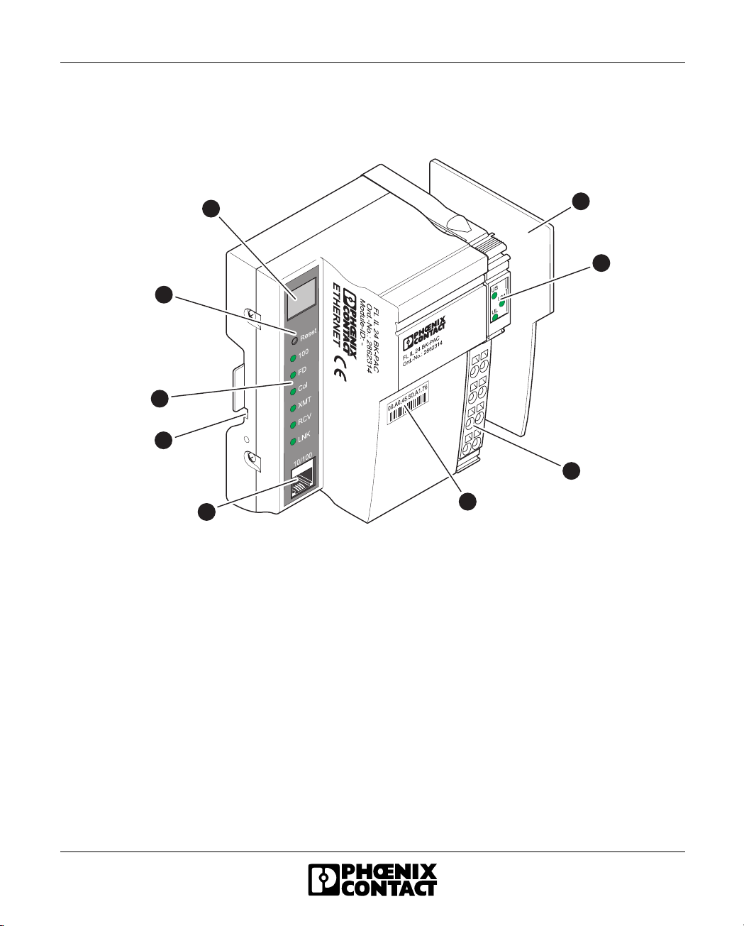
Figure 1-1 Front view of the FL IL 24 BK(-PAC)
1 2
1
2
3
4
6 1 5 5 0 0 0 2
1
2
3
4
1-4 615605
Page 19
FL IL 24 BK(-PAC)
1.2 Structure of the FL IL 24 BK(-PAC)
Bus Coupler
9
1
2
8
7
6
3
5
Figure 1-2 Structure of the FL IL 24 BK(-PAC) bus coupler
The bus coupler has the following components:
1 End plate to protect the last Inline module
2 Inline diagnostic indicators
3 24 V DC supply and functional earth ground connector
(not supplied as standard - order as an accessory)
4 MAC address in clear text and as a barcode
5 Ethernet interface (twisted pair cables in RJ45 format)
6 Two FE contacts for grounding the bus coupler using a DIN rail
(on the back of the module)
7 Ethernet status and diagnostic indicators
8 Reset button
9 7-segment display for the device status (Ethernet communication unit)
4
615605 1-5
Page 20

FL IL 24 BK-PAC UM E
1.2.1 Local Status and Diagnostic Indicators
Table 1-1 Local status and diagnostic indicators
Des. Color Status Meaning
Module Electronics
UL Green ON 24 V supply, 7 V communications power/interface supply present
OFF 24 V supply, 7 V communications power/interface supply not present
UM Green ON 24 V main circuit supply present
OFF 24 V main circuit supply not present
US Green ON 24 V segment supply present
OFF 24 V segment supply not present
Ethernet Port
100 Green ON Operation at 100 Mbps
OFF Operation at 10 Mbps (if LNK LED active)
FD Green ON Data transmission in full duplex mode
OFF Data transmission in half duplex mode (if LNK LED active)
COL Red ON Collision of data telegrams
OFF Transmission of telegrams without a collision (if LNK LED active)
XMT Green ON Data telegrams are being sent
OFF Data telegrams are not being sent
RCV Yellow ON Data telegrams are being received
OFF Data telegrams are not being received
LNK Green ON Physical network connection ready to operate
OFF Physical network connection interrupted or not present
Reset button
The reset button is on the front plate. When the reset button is pressed the bus
coupler is completely initialized and booted. Inline system outputs are reset and
inputs are not read.
1-6 615605
Page 21

1.3 Connecting the Supply Voltage
The module is operated using a +24 V DC SELV.
Typical Connection of the Supply Voltage
U S
U M
U L
I n t e r n a l j u m p e r
( i n t h e m o d u l e )
1 2
1
1
2
2
+
3
3
-
S G N D
4
4
1 0 0
F D
C O L
X M T
R C V
L I N K
1 0 / 1 0 0
R E S E T
F L I L 2 4 B K - P A C
O r d . - N o . : 2 8 6 2 3 1 4
U
L G N D
B K
FL IL 24 BK(-PAC)
+
U
S
+
-
U
M
-
6 1 5 5 1 0 1 1
Figure 1-3 Typical connection of the supply voltage
615605 1-7
Page 22

FL IL 24 BK-PAC UM E
1.4 Connector Assignment
Table 1-2 Connector assignment
Termina l
Assignment/Power Connector Wire Color/Remark
Point/
Connector
1.1 24 V DC
)
(U
S
1.2 24 V DC
(U
BK
2.1, 2.2 24 V DC
24 V segment supply The supplied voltage is directly led to the potential jumper.
24 V supply The communications power for the bus coupler and the
)
Main voltage The main voltage is routed to the local bus devices via the
(UM)
1.3 LGND Reference potential
logic ground for U
BK
2.3 SGND Reference potential
and U
for U
S
M
1.4, 2.4 FE Functional earth
ground (FE)
connected local bus devices is generated from this power.
The 24 V analog power (U
) for the local bus devices is
ANA
also generated.
potential jumpers.
The potential is the reference ground for the communications
power U
BK
.
The reference potential is directly led to the potential jumper
and is, at the same time, ground reference for the main and
segment supply.
The functional earth ground must be connected to the 24 V
DC supply/functional earth ground connection. The contacts
are directly connected to the potential jumper and FE springs
on the bottom of the housing. The terminal is grounded when
it is snapped onto a grounded DIN rail. Functional earth
ground is only used to discharge interference.
The GND potential jumper carries the total current from the main and segment
circuits. The total current must not exceed the maximum current carrying capacity
of the potential jumper (8 A). If the 8 A limit is reached at one of the potential
jumpers U
, UM, and GND during configuration, a new power terminal must be
S
used.
Functional earth ground must be connected through the 24 V DC supply/
functional earth ground connection.
1-8 615605
Page 23

FL IL 24 BK(-PAC)
1.5 Supported Inline Modules
Table 1-3 Digital Input/Output Modules
Designation Properties Order No.
IB IL 24 DI 2 2 inputs, 4-wire termination, 24 V DC 27 26 20 1
IB IL 24 DI 2-PAC 2 inputs, 4-wire termination, 24 V DC 28 61 22 1
IB IL 24 DI 2-NPN 2 inputs with negative logic, 4-wire termination, 24 V DC 27 40 11 2
IB IL 24 DI 2-NPN-PAC 2 inputs with negative logic, 4-wire termination, 24 V DC 28 61 48 3
IB IL 24 EDI 2 2 inputs, 4-wire termination, with electronic overload protection
and diagnostics
IB IL 24 EDI 2-PAC 2 inputs, 4-wire termination, with electronic overload protection
and diagnostics
IB IL 24 EDI 2-DESINA 2 inputs, 4-wire termination according to Desina specification, with
electronic overload protection and diagnostics
IB IL 24
EDI 2-DESINA-PAC
IB IL 24 DI 4 4 inputs, 3-wire termination, 24 V DC 27 26 21 4
IB IL 24 DI 4-PAC 4 inputs, 3-wire termination, 24 V DC 28 61 23 4
IB IL 24 DI 8 8 inputs, 4-wire termination, 24 V DC 27 26 22 7
IB IL 24 DI 8-PAC 8 inputs, 4-wire termination, 24 V DC 28 61 24 7
IB IL 24 DI 8 T2 8 inputs, 4-wire termination, 24 V DC,
IB IL 24 DI 8 T2-PAC 8 inputs, 4-wire termination, 24 V DC,
IB IL 24 DI 16 16 inputs, 3-wire termination, 24 V DC 27 26 23 0
IB IL 24 DI 16-PAC 16 inputs, 3-wire termination, 24 V DC 28 61 25 0
IB IL 24 DI 16-NPN 16 inputs with negative logic,
IB IL 24 DI 16-NPN-PAC 16 inputs with negative logic, 3-wire termination,
IB IL 24 DI 32/HD 32 inputs, 1-wire termination, 24 V DC 28 60 78 5
IB IL 24 DI 32/HD-PAC 32 inputs, 1-wire termination, 24 V DC 28 62 83 5
IB IL 120 DI 1 1 input, 3-wire termination, 120 V AC 28 36 70 6
IB IL 120 DI 1-PAC 1 input, 3-wire termination, 120 V AC 28 61 91 7
IB IL 230 DI 1 1 input, 3-wire termination, 230 V AC 27 40 34 2
IB IL 230 DI 1-PAC 1 input, 3-wire termination, 230 V AC 28 61 54 8
IB IL 24 DO 2 2 outputs, 500 mA, 4-wire termination, 24 V DC 27 40 10 6
2 inputs, 4-wire termination according to Desina specification, with
electronic overload protection and diagnostics
according to EN 61131-2 Type 2
according to EN 61131-2 Type 2
3-wire termination, 24 V DC
24 V DC
27 42 60 9
28 61 62 9
27 40 32 6
28 61 52 2
28 60 43 9
28 62 20 4
28 63 51 7
28 63 52 0
615605 1-9
Page 24

FL IL 24 BK-PAC UM E
Table 1-3 Digital Input/Output Modules
Designation (Contd.) Properties Order No.
IB IL 24 DO 2-PAC 2 outputs, 500 mA, 4-wire termination, 24 V DC 28 61 47 0
IB IL 24 DO 2-2A 2 outputs, 2 A, 4-wire termination, 24 V DC 27 26 24 3
IB IL 24 DO 2-2A-PAC 2 outputs, 2 A, 4-wire termination, 24 V DC 28 61 26 3
IB IL 24 DO 2-NPN 2 outputs with negative logic, 500 mA, 4-wire termination, 24 V DC 27 40 11 9
IB IL 24 DO 2-NPN-PAC 2 outputs with negative logic, 500 mA, 4-wire termination, 24 V DC 28 61 49 6
IB IL 24 EDO 2 2 outputs, 500 mA, 4-wire termination, 24 V DC, extended
diagnostics, configurable outputs
IB IL 24 EDO 2-PAC 2 outputs, 500 mA, 4-wire termination, 24 V DC, extended
diagnostics, configurable outputs
IB IL 24 DO 4 4 outputs, 500 mA, 3-wire termination, 24 V DC 27 26 25 6
IB IL 24 DO 4-PAC 4 outputs, 500 mA, 3-wire termination, 24 V DC 28 61 27 6
IB IL 24 DO 8 8 outputs, 500 mA, 4-wire termination, 24 V DC 27 26 26 9
IB IL 24 DO 8-PAC 8 outputs, 500 mA, 4-wire termination, 24 V DC 28 61 28 9
IB IL 24 DO 8-NPN 8 outputs with negative logic, 500 mA,
4-wire termination, 24 V DC
IB IL 24 DO 8-NPN-PAC 8 outputs with negative logic, 500 mA,
4-wire termination, 24 V DC
IB IL 24 DO 8-2A 8 outputs, 2 A, 4-wire termination, 24 V DC 27 42 11 7
IB IL 24 DO 8-2A-PAC 8 outputs, 2 A, 4-wire termination, 24 V DC 28 61 60 3
IB IL 24 DO 16 16 outputs, 500 mA, 3-wire termination, 24 V DC 27 26 27 2
IB IL 24 DO 16-PAC 16 outputs, 500 mA, 3-wire termination, 24 V DC 28 61 29 2
IB IL 24 DO 32/HD 32 outputs, 500 mA, 1-wire termination, 24 V DC 28 60 93 4
IB IL 24 DO 32/HD-PAC 32 outputs, 500 mA, 1-wire termination, 24 V DC 28 62 82 2
IB IL DO 1 AC 1 output, 12 V - 253 V AC, 500 mA, 3-wire termination 28 36 74 8
IB IL DO 1 AC-PAC 1 output, 12 V - 253 V AC, 500 mA, 3-wire termination 28 61 92 0
IB IL DO 4 AC-1A 1 output, 12 V - 253 V AC, 1 A, 3-wire termination 27 42 69 6
IB IL DO 4 AC-1A-PAC 1 output, 12 V - 253 V AC, 1 A, 3-wire termination 28 61 65 8
IB IL 24/230 DOR 1/W 1 SPDT relay contact, 5 V - 253 V AC, 3 A 28 36 43 4
IB IL 24/230 DOR 1/W-
PAC
IB IL 24/230 DOR 1/W-PC 1 SPDT relay contact, 5 V - 253 V AC, 3 A, for inductive and
IB IL 24/230 DOR 1/WPC-PAC
1 SPDT relay contact, 5 V - 253 V AC, 3 A 28 61 88 1
capacitive loads
1 SPDT relay contact, 5 V - 253 V AC, 3 A, for inductive and
capacitive loads
27 42 59 9
28 61 61 6
28 63 54 6
28 63 53 3
28 60 40 0
28 62 17 8
1-10 615605
Page 25

FL IL 24 BK(-PAC)
Table 1-3 Digital Input/Output Modules
Designation (Contd.) Properties Order No.
IB IL 24/230 DOR 4/W 4 SPDT relay contacts, 5 V - 253 V AC, 3 A 28 36 42 1
IB IL 24/230 DOR 4/W-
4 SPDT relay contacts, 5 V - 253 V AC, 3 A 28 61 87 8
PAC
IB IL 24/230 DOR 4/W-PC 4 SPDT relay contacts, 5 V - 253 V AC, 3 A, for inductive and
28 60 41 3
capacitive loads
IB IL 24/230 DOR 4/W-
PC-PAC
4 SPDT relay contacts, 5 V - 253 V AC, 3 A, for inductive and
capacitive loads
28 62 18 1
IB IL 24/48 DOR/2W 2 SPDT relay contacts, 5 V - 50 V AC, 5 V - 120 V DC, 2 A 28 62 97 4
IB IL 24/48 DOR/2W-PAC 2 SPDT relay contacts, 5 V - 50 V AC, 5 V - 120 V DC, 2 A 28 63 11 9
Table 1-4 Analog input/output modules
Designation Properties Order No.
IB IL AI 2/4-20 2 inputs, 2-wire termination, 24 V DC, 0 -10 V, ±10 V,
28 60 44 2
0 - 20 mA, 4 - 20 mA, ±20 mA
IB IL AI 2/4-20-PAC 2 inputs, 2-wire termination, 24 V DC, 0 -10 V, ±10 V,
28 62 21 7
0 - 20 mA, 4 - 20 mA, ±20 mA
IB IL AI 2/SF 2 inputs, 2-wire termination, 24 V DC, 0 -10 V, ±10 V,
27 26 28 5
0 - 20 mA, 4 - 20 mA, ±20 mA, 0 - 40 mA, ±40 mA
IB IL AI 2/SF-PAC 2 inputs, 2-wire termination, 24 V DC, 0 -10 V, ±10 V,
28 61 30 2
0 - 20 mA, 4 - 20 mA, ±20 mA, 0 - 40 mA, ±40 mA
IB IL AI 2/SF-230 2 inputs, 2-wire termination, 24 V DC, 0 -10 V, ±10 V,
27 40 81 8
0 - 20 mA, 4 - 20 mA, ±20 mA, 0 - 40 mA, ±40 mA, 230 Hz
IB IL AI 2/SF-230-PAC 2 inputs, 2-wire termination, 24 V DC, 0 -10 V, ±10 V,
28 61 57 7
0 - 20 mA, 4 - 20 mA, ±20 mA, 0 - 40 mA, ±40 mA, 230 Hz
IB IL AI 8/SF 8 inputs, 2-wire termination, 24 V DC, 0 - 5 V, 0 - 10 V, ±10 V, 0 -
27 27 83 1
25 V, 0 - 20 mA, 4 - 20 mA, ±20 mA, 0 - 40 mA
IB IL AI 8/SF-PAC 8 inputs, 2-wire termination, 24 V DC, 0 - 5 V, 0 - 10 V, ±10 V, 0 -
28 61 41 2
25 V, 0 - 20 mA, 4 - 20 mA, ±20 mA, 0 - 40 mA
IB IL AI 8/IS 8 inputs, 3-wire termination, 24 V DC, 0 - 20 mA,
27 42 74 8
4 - 20 mA, ±20 mA, 0 - 40 mA, ±40 mA
IB IL AI 8/IS-PAC 8 inputs, 3-wire termination, 24 V DC, 0 - 20 mA,
28 61 66 1
4 - 20 mA, ±20 mA, 0 - 40 mA, ±40 mA
IB IL AI 2-HART 2 inputs, 2-wire termination 24 V DC, 0 - 25 mA, 4 - 20 mA, HART
28 60 26 4
functionality, HART protocol transmission
IB IL AI 2-HART-PAC 2 inputs, 2-wire termination 24 V DC, 0 - 25 mA, 4 - 20 mA, HART
28 62 14 9
functionality, HART protocol transmission
615605 1-11
Page 26
FL IL 24 BK-PAC UM E
Table 1-4 Analog input/output modules
Designation (Contd.) Properties Order No.
IB IL TEMP 2 RTD 2 inputs, 4-wire termination, 16 bits, resistance sensors 27 26 30 8
IB IL TEMP 2 RTD-PAC 2 inputs, 4-wire termination, 16 bits, resistance sensors 28 61 32 8
IB IL TEMP 2 RTD/300 2 inputs, 4-wire termination, 16 bits, resistance sensors 27 40 76 6
IB IL TEMP 2 RTD/300-
PAC
IB IL TEMP 2 UTH 2 inputs, 2-wire termination, 16 bits, thermocouples 27 27 76 3
IB IL TEMP 2 UTH-PAC 2 inputs, 2-wire termination, 16 bits, thermocouples 28 61 38 6
IB IL TEMPCON RTD Multi-channel temperature controller, 6 inputs/6 outputs 28 19 24 4
IB IL TEMPCON RTD-
PAC
IB IL TEMPCON UTH 8 inputs, 8 outputs, controller functions 28 19 31 2
IB IL TEMPCON UTH-
PAC
IB IL AO 1/SF 1 output, 2-wire termination, 24 V DC, 0-20 mA,
IB IL AO 1/SF-PAC 1 output, 2-wire termination, 24 V DC, 0-20 mA,
IB IL AO 1/U/SF 1 output, 2-wire termination, 24 V DC, 0-10 V 27 27 77 6
IB IL AO 1/U/SF-PAC 1 output, 2-wire termination, 24 V DC, 0-10 V 28 61 39 9
IB IL AO 2/SF 2 outputs, 2-wire termination, 24 V DC, 0-20 mA,
IB IL AO 2/SF-PAC 2 outputs, 2-wire termination, 24 V DC, 0-20 mA,
IB IL AO 2/U/BP 2 outputs, 2-wire termination, 24 V DC, 0 - 10 V, ±10 V 27 32 73 2
IB IL AO 2/U/BP-PAC 2 outputs, 2-wire termination, 24 V DC, 0 - 10 V, ±10 V 28 61 46 7
2 inputs, 4-wire termination, 16 bits, resistance sensors 28 61 55 1
Multi-channel temperature controller, 6 inputs/6 outputs 28 61 77 1
8 inputs, 8 outputs, controller functions 28 61 80 7
27 26 29 8
4-20 mA, 0-10 V
28 61 31 5
4-20 mA, 0-10 V
28 62 80 6
4-20 mA, 0-10 V
28 63 08 3
4-20 mA, 0-10 V
Table 1-5 Special function modules
Designation Properties Order No.
IB IL SSI 1 absolute encoder input, 4 digital inputs, 4 digital outputs, 500
mA, 3-wire termination, 24 V DC
IB IL SSI-PAC 1 absolute encoder input, 4 digital inputs, 4 digital outputs, 500
mA, 3-wire termination, 24 V DC
IB IL SSI-IN 1 absolute encoder input, 24 V DC 28 19 30 9
IB IL SSI-IN-PAC 1 absolute encoder input, 24 V DC 28 19 57 4
1-12 615605
28 36 34 0
28 61 86 5
Page 27

FL IL 24 BK(-PAC)
Table 1-5 Special function modules
Designation Properties Order No.
IB IL INC 1 incremental encoder input, 4 digital inputs, 4 digital outputs, 500
28 36 32 4
mA, 3-wire termination, 24 V DC
IB IL INC-PAC 1 incremental encoder input, 4 digital inputs, 4 digital outputs, 500
28 61 84 9
mA, 3-wire termination, 24 V DC
IB IL INC-IN 1 incremental encoder input with square-wave signal, 1 digital
28 19 22 8
signal for reference signal, 2 digital inputs, 24 V DC
IB IL INC-IN-PAC 1 incremental encoder input with square-wave signal, 1 digital
28 61 75 5
signal for reference signal, 2 digital inputs, 24 V DC
IB IL CNT 1 counter input, 1 control input, 1 digital output, 500 mA, 3-wire
28 36 33 7
termination, 24 V DC
IB IL CNT-PAC 1 counter input, 1 control input, 1 digital output, 500 mA, 3-wire
28 61 85 2
termination, 24 V DC
IB IL IMPULSE IN 1 input for magnetostrictive length measuring systems with pulse
28 19 23 1
interface
IB IL IMPULSE IN-PAC 1 input for magnetostrictive length measuring systems with pulse
28 61 85 2
interface
IB IL POS 200 Inline positioning control 28 19 33 8
IB IL POS 200-PAC Inline positioning control including accessories 28 61 82 3
IB IL RS 232 Terminal for serial data transmission via RS 232 27 27 34 9
IB IL RS 232-PAC Terminal for serial data transmission via RS 232 28 61 35 7
IB IL RS 485/422 Terminal for serial data transmission via RS 485/422 28 36 79 3
IB IL RS 485/422-PAC Terminal for serial data transmission via RS 485/422 28 61 93 3
ASI MA IB IL AS-i/master 27 41 28 8
Table 1-6 Motor terminal blocks
Designation Properties Order No.
IB IL 24 TC Thermistor terminal 27 27 41 7
IB IL 24 TC-PAC Thermistor terminal 28 61 36 0
IB IL 400 ELR 1-3A Electronic direct starter, 1.5 kW (2.01 hp), 400 V AC 27 27 35 2
IB IL 400 ELR R-3A Electronic reversing-load starter, 1.5 kW (2.01 hp), 400 V AC 27 27 37 8
IB IL 400 MLR 1-8A Electromechanical direct starter, 3.7 kW (4.96 hp), 400 V AC 27 27 36 5
IB IL DC AR 48/10A Servo amplifier for DC motors with brushgears 28 19 28 6
IB IL EC AR 48/10A Servo amplifier for DC motor without brushgears (EC motor) 28 19 25 7
615605 1-13
Page 28

FL IL 24 BK-PAC UM E
Table 1-6 Motor terminal blocks
Designation Properties Order No.
IB IL EC AR 48/10A-PAC Servo amplifier for DC motor without brushgears (EC motor) 28 19 58 7
IB IL PWM/2 Terminal for pulse width modulation and frequency modulation or
stepper motor control, 2 outputs for 5 V or 24 V
IB IL PWM/2-PAC Terminal for pulse width modulation and frequency modulation or
stepper motor control, 2 outputs for 5 V or 24 V
Table 1-7 Power and segment terminals
Designation Properties Order No.
IB IL 24 PRW IN Power terminal, 24 V DC 27 26 31 1
IB IL 24 PRW IN-PAC Power terminal, 24 V DC 28 61 33 1
IB IL 24 PRW IN/F Power terminal, 24 V DC with fuse 27 27 90 9
IB IL 24 PRW IN/F-PAC Power terminal, 24 V DC with fuse 28 61 43 8
IB IL 24 PRW IN/F-D Power terminal, 24 V DC with fuse and diagnostics 28 36 66 7
IB IL 24 PRW IN/F-D-PAC Power terminal, 24 V DC with fuse and diagnostics 28 61 89 4
IB IL 24 PRW IN/2-F Power terminal, 24 V DC with fuse 28 60 01 5
IB IL 24 PRW IN/2-F-PAC Power terminal, 24 V DC with fuse 28 62 13 6
IB IL 24 PRW IN/2-F-D Power terminal, 24 V DC with fuse and diagnostics 28 60 28 0
IB IL 24 PRW IN/2-F-D-
PAC
IB IL 24 PWR IN/M Power terminal, 24 V DC 28 61 02 7
IB IL 24 PWR IN/R Power terminal, 24 V DC 27 42 76 4
IB IL 24 PWR IN/R-PAC Power terminal, 24 V DC 28 61 67 4
IB IL 120 PRW IN Power terminal, 120 V AC with fuse 27 31 70 4
IB IL 120 PRW IN-PAC Power terminal, 120 V AC with fuse 28 61 45 4
IB IL 230 PRW IN Power terminal, 230 V AC with fuse 27 40 33 9
IB IL 230 PRW IN-PAC Power terminal, 230 V AC with fuse 28 61 53 5
IB IL 24 SEG Segment terminal, 24 V DC 27 26 32 4
IB IL 24 SEG-PAC Segment terminal, 24 V DC 28 61 34 4
IB IL 24 SEG/F Segment terminal, 24 V DC with fuse 27 27 74 7
IB IL 24 SEG/F-PAC Segment terminal, 24 V DC with fuse 28 61 37 3
IB IL 24 SEG/F-D Segment terminal, 24 V DC with fuse and diagnostics 28 36 68 3
IB IL 24 SEG/F-D-PAC Segment terminal, 24 V DC with fuse and diagnostics 28 61 90 4
IB IL 24 SEG-ELF Segment terminal, 24 V DC with electronic fuse 27 27 78 9
Power terminal, 24 V DC with fuse and diagnostics 28 62 15 2
27 42 61 2
28 61 63 2
1-14 615605
Page 29

FL IL 24 BK(-PAC)
Table 1-7 Power and segment terminals
Designation Properties Order No.
IB IL 24 SEG-ELF-PAC Segment terminal, 24 V DC with electronic fuse 28 61 40 9
IB IL PD GND Terminal for GND potential distribution 28 63 06 7
IB IL PD GND-PAC Terminal for potential distribution (GND) 28 62 99 0
IB IL PD 24V Terminal for potential distribution (main voltage) 28 63 05 4
IB IL PD 24V-PAC Terminal for potential distribution (main voltage) 28 62 98 7
Table 1-8 Safety
Designation Properties Order No.
IB IL 24 SAFE 1 Safety terminal with 2 N/O contacts 27 40 78 2
IB IL 24 SAFE 1-PAC Safety terminal with 2 N/O contacts 28 61 56 4
IB IL 400 SAFE 2 Safety terminal with 3 N/O contacts and 1 N/C contact, 200 V AC
27 40 79 5
to 600 V AC
Table 1-9 Controller / CPU
Designation Properties Order No.
ILC 200 UNI Inline Controller with INTERBUS local bus interface 27 30 90 9
ILC 200 UNI-PAC Inline Controller with INTERBUS local bus interface 28 62 29 1
IB IL 332-128 Inline CPU 28 19 13 4
IB IL 332-128-PAC Inline CPU 28 61 73 9
IB IL 332-256 Inline-CPU with 256 kbytes RAM, 1 MB flash, serial interface 28 19 32 5
IB IL 332-256-PAC Inline-CPU with 256 kbytes RAM, 1 MB flash, serial interface 28 61 81 0
615605 1-15
Page 30
FL IL 24 BK-PAC UM E
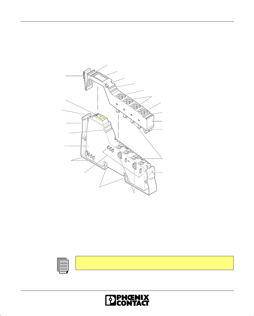
B a c k
c o n n e c t o r s h a f t l a t c h
D i a g n o s t i c a n d s t a t u s
i n d i c a t o r s
1.6 Basic Structure of Low-Level Signal Modules
Regardless of the function and the design width, an Inline low-level signal module
consists of the electronics base (or base for short) and the plug-in connector (or
connector for short).
Z B F M l a b e l i n g f i e l d f o r c o n n e c t o r
T r a n s p a r e n t f i e l d
A t t a c h m e n t f o r l a b e l i n g f i e l d
Z B F M l a b e l i n g f i e l d f o r s i g n a l 1 / 2
S i g n a l t e r m i n a l s 1 / 2
V o l t a g e t e r m i n a l s
F E o r s i g n a l t e r m i n a l s 3 / 4
F u n c t i o n c o l o r c o d i n g
B a c k
s n a p - o n m e c h a n i s m
Z B F M l a b e l i n g f i e l d
f o r m o d u l e i d e n t i f i c a t i o n
E l e c t r o n i c s b a s e
D a t a r o u t i n g
P o t e n t i a l r o u t i n g
Z B F M l a b e l i n g f i e l d f o r s i g n a l 3 / 4
C o n n e c t o r
F r o n t
c o n n e c t o r s h a f t l a t c h
S l o t c o d i n g
F r o n t
s n a p - o n m e c h a n i s m
L a t c h f o r
D I N r a i l
F e a t h e r k e y f o r
k e y / f e a t h e r k e y c o n n e c t i o n
5 5 2 0 A 0 3 3
Figure 1-4 Basic structure of an Inline module
The most important components shown in Figure 1-4 are described in sections
"Electronics Base" on page 1-17 and "Connectors" on page 1-17.
ZBFM: Zack marker strips, flat
(see also Section "Function Identification and Labeling" on
page 1-21)
The components required for labeling are listed in the Phoenix Contact
"CLIPLINE" catalog.
1-16 615605
Page 31

FL IL 24 BK(-PAC)
1.6.1 Electronics Base
The electronics base holds the entire electronics for the Inline module and the
potential and data routing.
Design widths The electronics bases for low-level signal modules are available in a width of 8
terminal points (8-slot terminal) or 2 terminal points (2-slot terminal). Exceptions are
combinations of these two basic terminal widths (see also Section "Dimensions of
Low-Level Signal Modules" on page 1-24).
1.6.2 Connectors
The I/O or supply voltages are connected using a pluggable connector.
Advantages This pluggable connection offers the following advantages:
– Simple exchange of module electronics for servicing. There is no need to
remove the wiring.
– Different connectors can be used on one electronics base, depending on your
requirements.
Connector width Regardless of the width of the electronics base, the connectors have a width of two
terminal points. This means that you must plug 1 connector on a 2-slot base, 2
connectors on a 4-slot base, and 4 connectors on an 8-slot base.
Connector types The following connector types are available:
1
Figure 1-5 Inline connector types
615605 1-17
2
3
6 1 5 6 0 0 1 0
Page 32

FL IL 24 BK-PAC UM E
1 Standard connector
The green standard connector is used for the connection of two signals in
4-wire technology (e.g., digital I/O signals).
The black standard connector is used for supply terminals. The adjacent
contacts are jumpered internally (see Figure 1-6 on page 1-19).
2 Shield connector
This green connector is used for signals connected using shielded cables
(e.g., analog I/O signals).
FE or shielding is connected via a shield connection clamp rather than via a
terminal point.
3 Extended double signal connector
This green connector is used for the connection of four signals in 3-wire
technology (e.g., digital I/O signals).
Connector
identification
All connectors are offered with and without color print. The connectors with color
print (marked with CP in the Order Designation) have terminal points that are colorcoded according to their functions.
The following colors indicate the signals of the terminal points:
Table 1-10 Terminal point color-coding
Color Terminal Point Signal
Red +
Blue -
Green/yellow Functional earth ground
1-18 615605
Page 33

Internal structure of the
connectors
A B C
FL IL 24 BK(-PAC)
D
1 2
1
1
2
2
3
3
4
4
1 2
1
1
2
2
3
3
4
4
1 2
1
1
2
2
3
3
4
4
1 2
1
2
3
4
565
1
2
3
4
6
6 1 5 6 0 0 1 1
Figure 1-6 Internal structure of the connectors
A Green connector for I/O connection
B Black connector for supply terminals
C Shield connector for analog terminals
D Double signal connector for I/O connection
Jumpered terminal points already integrated in the connectors are shown in
Figure 1-6.
The shield connector is jumpered through the shield connection. All other
connectors are jumpered through terminal point connection.
To avoid a malfunction, only snap a connector on a terminal that is appropriate
for this connection. Refer to the module-specific data sheet to select the correct
connectors.
The black connector must not be placed on a module for which a double signal
connector is to be used. Mixing this up leads to a short circuit between two signal
terminal points (1.4 - 2.4).
Only snap black connectors onto a supply terminal.
When the terminal points are jumpered in the black connector, power is carried
through the jumpering in the connector and not through the printed circuit board
of the module.
615605 1-19
Page 34

FL IL 24 BK-PAC UM E
Connector keying You can prevent mismatching of connectors by keying the base and the connector.
A
1
2
1
1
Figure 1-7 Connector keying
• Plug a keying profile (disc) into the keyway in the base (1) and turn it away from
the small plate (2) (Figure 1-7, detail A).
• Use a diagonal cutter to cut off the keying tab from the connector (Figure 1-7,
detail B).
Now, only the base and connector with the same keying will fit together (Figure 1-7,
detail C).
B
1
C
1
6 1 5 6 0 0 1 2
1-20 615605
Page 35

FL IL 24 BK(-PAC)
1.7 Function Identification and Labeling
Function identification The modules are color-coded to enable visual identification of the functions (1 in
Figure 1-8).
.
1
5 5 2 0 A 0 7 5
Figure 1-8 Function identification
The following colors indicate the functions:
Table 1-11 Module color-coding
Color Function of the Module
Light blue Digital input 24 V DC area
Pink Digital output 24 V DC area
Blue Digital input 120/230 V AC area
Red Digital output 120/230 V AC area
Green Analog input
Yellow Analog output
Orange Fieldbus coupler, special function modules
Black Power terminal/segment terminal
Connector
The color-coding of the terminal points is described on page 1-18.
identification
615605 1-21
Page 36

FL IL 24 BK-PAC UM E
Labeling/
Terminal point numbering is illustrated using the example of an 8-slot module.
terminal numbering
1 . 1
1 . 2
1 . 3
1 . 4
X . Y
1
2 3
1
2
1
2
3
4
2 . 1
1
2 . 2
2
2 . 3
3
2 . 4
4
1 2
1 2
1
1
1
2
2
2
3
3
3
4
4
4
4
1 2
1 2
1
1
1
1
1
2
2
2
2
2
3
3
3
3
4
4
3
4
4
4
1
2
3
4
5 5 2 0 A 0 3 5
Figure 1-9 Terminal point numbering
Slot/connector The slots (connectors) on a base are numbered consecutively (1 in Figure 1-9).
This numbering is not shown on the actual module.
Terminal point The terminal points on each connector are marked X.Y.
X is the number of the terminal point row on the connector. It is indicated above the
terminal point row (2 in Figure 1-9).
Y is the terminal point number in a row. It is directly indicated on the terminal point
(3 in Figure 1-9).
The precise designation for a connection point is thus specified by the slot and
terminal point. The highlighted terminal point (4 in Figure 1-9) would be numbered
as follows: slot 3, terminal point 2.3.
Additional labeling In addition to this module marking, you can identify the slots, terminal points, and
connections using marker strips and labeling fields.
1-22 615605
Page 37

FL IL 24 BK(-PAC)
1
6
Figure 1-10 Labeling of modules
3
2
4
5
5 5 2 0 A 0 3 6
Various options are available for labeling the slots and terminal points:
1 Each connector can be labeled individually with Zack marker strips.
2 / 3 Another option is to use a large labeling field. This labeling field is available
in two widths, either as a labeling field covering one connector (2) or as a
labeling field covering four connectors (3). You can label each channel
individually with free text. On the upper connector head there is a keyway
for attaching this labeling field. The labeling field can be tilted up and down.
In each end position there is a small latch which ensures that the labeling
field remains in place.
4 / 5 Each signal can be labeled individually using Zack markers. On a double
signal connector, the upper keyway (4) is designed for labeling signals 1/2
and the lower keyway (5) is for signals 3/4.
6 On the electronics base each slot can be labeled individually using Zack
markers. These markers are covered when a connector is plugged in.
615605 1-23
Page 38

FL IL 24 BK-PAC UM E
Using the markers on the connector and on the electronics base, you can clearly
assign both connector and slot.
The components required for labeling are listed in the Phoenix Contact
"CLIPLINE" catalog.
1.8 Dimensions of Low-Level Signal Modules
Today, small I/O stations are frequently installed in 80 mm (3.150 in.) standard
control boxes. Inline modules are designed so that they can be used in this type of
control box.
The housing dimensions of a module are determined by the dimensions of the
electronics base and the dimensions of the connector.
The electronics bases of the low-level signal modules are available in three design
widths (12.2 mm [0.480 in], 24.4 mm [0.961 in.] and 48.8 mm [1.921 in.]).
It accepts either one, two, or four 12.2 mm (0.480 in.) wide connectors.
When a connector is plugged in, each terminal depth is 71.5 mm (2.815 in.).
The height of the module depends on the connector used. The connectors are
available in three different versions (see Figure 1-14).
2-slot housing
7 1 . 5 m m ( 2 . 8 1 5 " )
1 2 0 m m ( 4 . 7 2 4 " )
1 2 . 2 m m
( 0 . 4 8 0 " )
5 5 2 0 1 0 2 3
Figure 1-11 Dimensions of the electronics bases (2-slot housing)
1-24 615605
Page 39

FL IL 24 BK(-PAC)
4-slot housing
8-slot housing
7 1 . 5 m m ( 2 . 8 1 5 " )
1 2 0 m m ( 4 . 7 2 4 " )
2 4 . 4 m m
( 0 . 9 6 1 " )
5 5 2 0 1 0 2 2
Figure 1-12 Dimensions of the electronics bases (4-slot housing)
7 1 . 5 m m ( 2 . 8 1 5 " )
1 2 0 m m ( 4 . 7 2 4 " )
4 8 . 8 m m
( 1 . 9 2 1 " )
5 5 2 0 1 0 2 4
Figure 1-13 Dimensions of the electronics bases (8-slot housing)
615605 1-25
Page 40

FL IL 24 BK-PAC UM E
Connector
A B C
1 2
1
1
2
2
3
1 1 2 . 4 m m ( 4 . 4 2 5 " )
3
4
4
1 3 2 m m ( 5 . 1 9 7 " )
1 2
1
1
2
2
3
3
4
4
1 3 7 m m ( 5 . 3 9 4 " )
1 2 . 2 m m
( 0 . 4 8 0 " )
1 2 . 2 m m
( 0 . 4 8 0 " )
1 2
1
2
3
4
565
1
2
3
4
6
1 2 . 2 m m
( 0 . 4 8 0 " )
5 5 2 0 0 0 5 8
Figure 1-14 Connector dimensions
Key:
A Standard connector
B Shield connector
C Extended double signal connector
The depth of the connector does not influence the overall depth of the module.
1-26 615605
Page 41

FL IL 24 BK(-PAC)
1.9 Electrical Potential and Data Routing
An important feature of the INTERBUS Inline and Ethernet/Inline bus coupler
product ranges is their internal potential routing system. The electrical connection
between the individual station devices is created automatically when the station is
installed. When the individual station devices are connected, a power rail is created
for the relevant circuit. It is created mechanically through the interlocking of knife
and featherkey contacts on the adjacent modules.
A special segment circuit eliminates the need for additional external potential
jumpering to neighboring modules.
Two independent circuits are created in one station: the logic circuit and the I/O
circuit.
1 2 3
4 5 6 7
9
Figure 1-15 Potential and data routing
a b c
8
6 1 5 6 0 0 1 7
615605 1-27
Page 42

FL IL 24 BK-PAC UM E
Table 1-12 Potential jumper (see Figure 1-15)
No. Function Meaning
1 FE FE Functional earth ground
2 SGND SGND Ground of segment supply and main supply
324 V U
424 V U
M
S
Supply for main circuit (with overload protection, if necessary)
Supply for segment circuit (with overload protection, if necessary)
This jumper does not exist in the120/230 V AC power levels.
5LGNDU
624 V U
7 7.5 V U
L-
ANA
L+
Ground of communications power and I/O supply for analog modules
I/O supply for analog modules
Supply for module electronics
(9) FE spring FE contact to DIN rail
The GND potential jumper carries the total current from the main and segment
circuits. The total current must not exceed the maximum current carrying capacity
of the potential jumper (8 A). If the 8 A limit is reached at one of the potential
jumpers U
, UM, and GND during configuration, a new power terminal must be
S
used.
The FE potential jumper must be connected via terminal point 1.4 or 2.4 at the
Ethernet bus coupler to a grounding terminal (see Figure 1-9). The FE potential
jumper is led through all of the modules and connected via the FE spring to the
grounded DIN rail of every supply terminal.
Table 1-13 Data jumper (see Figure 1-15)
No. Function Meaning
8a DI1 Local bus signal (Data IN)
8b DO1 Local bus signal (Data OUT)
8c DCLK Clock signal, local bus
1-28 615605
Page 43

FL IL 24 BK(-PAC)
1.10 Circuits Within an Inline Station and Provision
of the Supply Voltages
There are several circuits within an Inline station. These are automatically set up
when the modules have been properly installed. The voltages of the different
circuits are supplied to the connected modules via the potential jumpers.
Please refer to the module-specific data sheet for the circuit to which the I/O
circuit of a special module is to be connected.
Load capacity of the
jumper contacts
Observe the maximum current carrying capacity of the jumper contacts on the side
for each circuit. The load capacities for all potential jumpers are given in the
following sections.
The arrangement of the potential jumpers can be found in Section "Electrical
Potential and Data Routing" on page 1-27.
For voltage connection, please refer to the notes given in the module-specific
data sheets.
615605 1-29
Page 44

FL IL 24 BK-PAC UM E
1.10.1 Supply of the Ethernet Bus Coupler
The supply voltage UBK and the segment voltage US must be connected to the
Ethernet bus coupler. From the supply voltage U
(7.5 V) and the supply of the modules for analog signals U
U
L
internally generated. The segment voltage is used to supply the sensors and
actuators.
F L I L 2 4 B K - P A C
O r d . - N o . : 2 8 6 2 3 1 4
R E S E T
1 0 0
F D
C O L
X M T
L G N D
U
B K
+
-
R C V
L I N K
1 0 / 1 0 0
, the voltages for the logic circuit
BK
U S
U M
U L
1 2
1
2
3
4
I n t e r n a l j u m p e r
( i n t h e m o d u l e )
1
2
+
3
-
S G N D
4
U
ANA
+
-
M
(24 V) are
U
S
6 1 5 5 1 0 1 1
Figure 1-16 Typical connection of the supply voltage
1.10.2 Logic Circuit U
L
The logic circuit with communications power UL starts at the bus coupler, is led
through all modules of a station and cannot be supplied via another supply terminal.
Function The logic circuit provides the communications power for all modules in the station.
Voltage The voltage in this circuit is 7.5 V DC.
1-30 615605
Page 45

FL IL 24 BK(-PAC)
Provision of U
L
The communications power UL is generated from the supply voltage UBK of the bus
coupler.
The communications power is not electrically isolated from the 24 V input voltage
for the bus coupler.
Current carrying
The maximum current carrying capacity of UL is 2 A.
capacity
1.10.3 Analog Circuit U
ANA
The analog circuit with the supply for the analog modules (also referred to as analog
voltage) U
an Inline station. Power cannot be supplied by the supply terminals. U
electrically isolated from U
is supplied at the bus coupler and is led through all the modules in
ANA
ANA
BK
.
is not
Function The module I/O devices for analog signals are supplied from the analog circuit.
Voltage The voltage in this circuit is 24 V.
Provision of U
ANA
The analog voltage U
is generated from the main voltage UBK of the bus
ANA
coupler.
Current carrying
The maximum current carrying capacity of U
ANA
is 0.5 A.
capacity
F L I L 2 4 B K - P A C
P W R I N
S E G / F
U
U
G N D L
L
A N A
U
S
U
M
U
M
6 1 5 6 0 0 0 1
Figure 1-17 Logic and analog circuit
FL IL 24 BK-PAC Ethernet bus coupler
PWR IN Power terminal
SEG/F Segment terminal with fuse as an example of a segment
terminal
615605 1-31
Page 46

FL IL 24 BK-PAC UM E
1.10.4 Main Circuit U
M
The main circuit with the main voltage UM starts at the bus coupler or a power
terminal and is led through all subsequent modules until it reaches the next power
terminal. A new circuit that is electrically isolated from the previous one begins at
the next power terminal.
Several power terminals can be used within one station.
Function Several independent segments can be created within the main circuit. The main
circuit provides the main voltage for these segments. For example, a separate
supply for the actuators can be provided in this way.
Voltage
The maximum voltage in this circuit is 24 V DC. UM can only be a maximum of
Current carrying
capacity
250 V AC
The maximum current carrying capacity is 8 A (total current with the segment
circuit). If the limit value of the common GND potential jumper for U
reached (total current of U
when using special PWR-IN modules.
and UM), a new power terminal must be used.
S
F L I L 2 4 B K - P A C
P W R I N
S E G / F
and US is
M
U
L
U
A N A
G N D L
U
S
U
M
U
M
U
M
6 1 5 6 0 0 0 2
Figure 1-18 Main circuit
FL IL 24 BK-PAC Ethernet bus coupler
PWR IN Power terminal
SEG/F Segment terminal with fuse as an example of a segment
terminal
Provision of U
M
In the simplest case, the main voltage UM can be supplied at the bus coupler. In this
case it is 24 V DC.
1-32 615605
Page 47

FL IL 24 BK(-PAC)
The main voltage UM can also be supplied via a power terminal. A power terminal
must be used if:
1 Different voltage areas (e.g., 120 V AC) are to be created.
2 Electrical isolation is to be created.
3 The maximum current carrying capacity of a potential jumper (UM, US or GND,
total current of U
and UM) is reached.
S
1.10.5 Segment Circuit
The segment circuit or auxiliary circuit with the segment voltage US starts at the
Ethernet bus coupler or a supply terminal (power terminal or segment terminal) and
is led through all subsequent modules until it reaches the next supply terminal.
Function You can use several segment terminals within a main circuit, and in this way
segment the main circuit. It has the same reference ground as the main circuit. This
means that circuits with different fuses can be created within the station without
external cross wiring.
Voltage The voltage in this circuit should not exceed 24 V DC.
Current carrying
capacity
The current carrying capacity is 8 A, maximum (total current with the main circuit).
If the limit value of the common potential jumper for U
current of U
and UM), a new power terminal must be used.
S
and/or US is reached (total
M
615605 1-33
Page 48

FL IL 24 BK-PAC UM E
Generation of U
S
There are various ways of providing the segment voltage US:
1 You can supply the segment voltage at the Ethernet/Inline bus coupler or a
power terminal.
2 You can tap the segment voltage from the main voltage at the Ethernet/Inline
bus coupler or a power terminal using a jumper or a switch.
3 You can use a segment terminal with a fuse. Within this terminal the segment
voltage is automatically tapped from the main power.
4 You can use a segment terminal without a fuse and tap the segment voltage
from the main voltage using a jumper or a switch.
With 120 V/230 V AC voltage levels, segments cannot be created. In this case,
only the main circuit is used.
F L I L 2 4 B K - P A C P W R I N
USU
M
U
M
S E G / F
6 1 5 6 0 0 0 3
U
L
U
A N A
G N D L
U
S
U
M
Figure 1-19 Segment circuit
FL IL 24 BK(-PAC) Ethernet/Inline bus coupler
PWR IN Power terminal
SEG/F Segment terminal with fuse as an example of a
segment terminal
1-34 615605
Page 49

FL IL 24 BK(-PAC)
1.11 Voltage Concept
The Ethernet bus coupler and the Inline local bus system have a defined voltage
and grounding concept.
This avoids an undesirable effect on I/O devices in the logic area, suppresses
undesirable compensating currents, and increases noise immunity.
Electrical isolation:
Ethernet
No electrical isolation
of the Inline
communications
power
Isolated supply for
logic and I/O devices
The Ethernet interface is electrically isolated from the bus coupler logic. The
Ethernet cable shield is directly connected to functional earth ground. The device
has two functional earth ground springs, which have contact to the DIN rail when
they are snapped on. The springs are used to discharge interference, rather than
serve as protective earth ground. To ensure effective interference discharge, even
for dirty DIN rails, functional earth ground is also led to terminals 1.4 and 2.4.
Always ground either terminal 1.4 or 2.4 (see Figure 1-32 on page 1-54). This also
grounds the Inline station of the bus coupler sufficiently up to the first power
terminal.
A 120 V AC or 230 V AC power terminal interrupts the FE potential jumper.
Therefore a 24 V DC power terminal, which is located directly behind such an area,
must also be grounded using the FE terminal point.
To avoid the flow of compensating currents, connect a suitably sized equipotential
bonding cable parallel to the Ethernet cable.
The bus coupler does not have electrical isolation for the Inline module
communications power. U
(24 V), UL (7.5 V), and U
BK
(24 V) are not electrically
ANA
isolated.
The logic and I/O devices can be supplied by separate power supply units. If you
wish to use different potentials for the communications power (U
segment/main voltage (U
), do not connect the GND and GND
S/UM
) and the
BK
UBK
grounds of
the supply voltages.
615605 1-35
Page 50

FL IL 24 BK-PAC UM E
Option 1 The Fieldbus coupler main voltage UM and the I/O supply US are provided
separately with the same ground potential from two voltage supplies:
C
m
1
L o c a l b u s
U
L +
U
A N A
U
( G N DM)
L -
4
3 . 3 V
2 4 V
2
7 . 5 V
5 V
2 4 V
2 4 V
+ 2 4 V ( U
3
+ 2 4 V ( UM)
)
S
U
U
M
S
2
U
B K
U B K
6 1 5 6 0 0 0 4
E t h e r n e t
G N D
Figure 1-20 Potential areas in the bus coupler (two voltage supplies)
Potential areas:
1 Ethernet interface area
2 Functional earth ground (PE) and (shield) Ethernet interface area
3 Main voltage U
and I/O voltage US area
M
4 Inline communications power
1-36 615605
Page 51
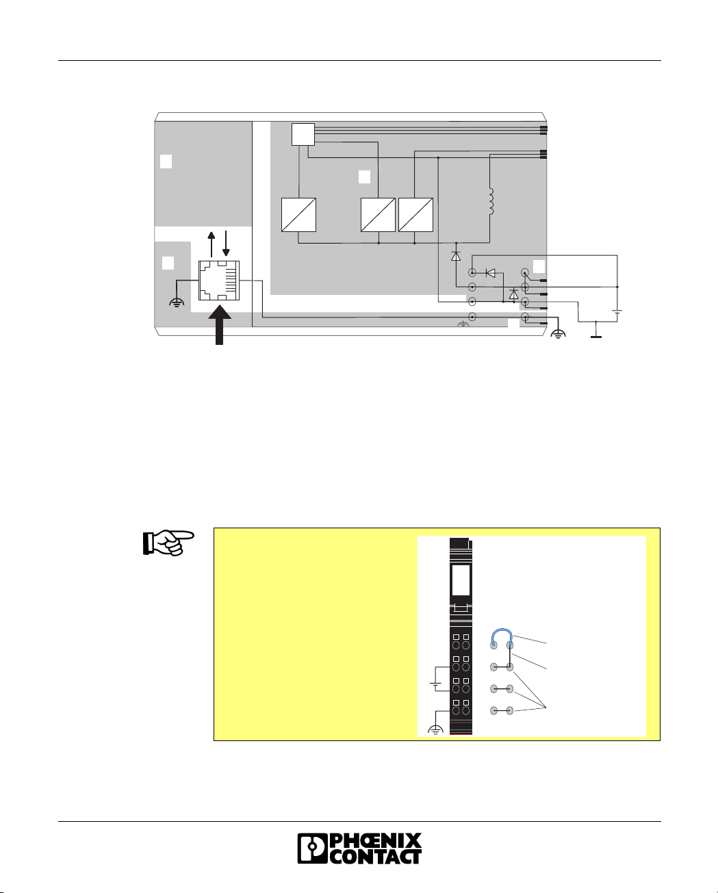
FL IL 24 BK(-PAC)
Option 2 Common supply of voltages UBK, UM, and US from one voltage supply:
+ 2 4 V ( U
3
+ 2 4 V ( UM)
L o c a l b u s
U
L +
U
A N A
U
( G N DM)
L -
)
S
U
B K
U
M
U
S
G N D
U B K
G N D
6 1 5 6 0 0 0 5
C
m
1
3
3 . 3 V
2 4 V
7 . 5 V
5 V
2 4 V
2 4 V
2
2
E t h e r n e t
Figure 1-21 Bus coupler potentials (one voltage supply)
Potential areas:
1 Ethernet interface area
2 Functional earth ground / (shield) Ethernet interface area, bus coupler
3 Main voltage U
and I/O voltage US area
M
The connector on the right can
only be used when all the
voltages supplied to the bus
I B I L S C N - P W R I N - C P
O r d e r N o . : 2 7 2 7 6 3 7
coupler have the same reference
potential. Simply insert the
external jumper to correctly
connect all the supply points (see
"Typical connection of the supply
voltage" on page 1-30).
2 4 V D C
G N D
1 2
1
1
1 . 1
2 . 1
E x t e r n a l j u m p e r
2
2
1 . 2
2 . 2
J u m p e r e d i n t h e
3
3
1 . 3
4
4
1 . 4
2 . 3
2 . 4
m o d u l e
J u m p e r e d i n t h e
c o n n e c t o r
6 1 5 6 0 0 2 1
Figure 1-22 Power connector for supply from a single power supply unit
615605 1-37
Page 52

FL IL 24 BK-PAC UM E
Potentials:
Digital module
L o c a l b u s
U
L
U
S
U
M
The isolation of the I/O circuit of a digital module to the communications power is
only ensured if U
and UM/US are provided from separate voltage supplies.
BK
An example of this principle is shown in Figure 1-23 on a section of an Inline station.
I B I L 2 4 D I 2 I B I L 2 4 D O 2 - 2 A
O P C
O P C
I B I L 2 4 P W R I NI B I L 2 4 P W R I N
U
S
U
M
U
S
U
M
6 1 5 6 0 0 1 3
Figure 1-23 Example: Interruption/creation of the potential jumpers using the
power terminal
The areas hatched in the figure show the points at which the potential
X X X X X
jumpers are interrupted.
1-38 615605
Page 53

FL IL 24 BK(-PAC)
Potentials:
Analog module
1
2
E t h e r n e t
The I/O circuit (measurement amplifier) of an analog module receives floating
power from the 24 V supply voltage U
isolation is a component of an analog module. The voltage U
. The power supply unit with electrical
ANA
is looped through
ANA
in each module and, in this way, is also available to the next module.
F L I L 2 4 B K - P A C
C
m
3 . 3 V
2 4 V
4
7 . 5 V
5 V
2 4 V
2 4 V
I B I L A I 2 / S F
O P C
E l e c t r o n i c s
I B I L A I 2 / S F
µ P
M U X
R E F
E E P R O M
2 4 V
+ 5 V
/ + 1 0 V
L o c a l b u s
U
L +
U
A N A
U
( G N DM)
L -
3
U
S
U
4
M
2
U
, UM/ U
B K
S
Figure 1-24 Electrical isolation between Ethernet bus coupler and analog
module
6 1 5 6 0 0 0 6
The potential jumpers hatched in the figure are not used in the analog
module. This means that the 24 V supply of the bus coupler (U
X X X X X
) or the power
BK
terminal is always electrically isolated from the I/O circuit (measurement amplifier)
of the analog module. The I/O circuit of the analog module is supplied from the
analog circuit U
615605 1-39
ANA
.
Page 54

FL IL 24 BK-PAC UM E
I/O supply electrically
isolated from one
another
Several electrically isolated segment or main circuits can be created by using power
terminals. A power terminal interrupts the U
and GND potential jumpers and
S/UM
has terminal points for another power supply unit. In this way, the I/O circuits of the
Inline modules are electrically isolated from one another before and after the power
terminal.
During this process the 24 V power supply units on the low voltage side must not
be connected to one another.
One method of electrical isolation using a power terminal is illustrated in
Figure 1-25. If a number of grounds are connected, e.g., to functional earth ground,
electrical isolation is lost.
Because U
and UM can be supplied separately, it is possible to create separate
S
segment circuits using a segment terminal. Using a switch, it is possible, for
example, to create a switched segment circuit (see Figure 1-25 on page 1-41). U
and U
can be protected separately, yet still have a common ground potential.
M
Please observe the maximum total current of 8 A.
S
1-40 615605
Page 55
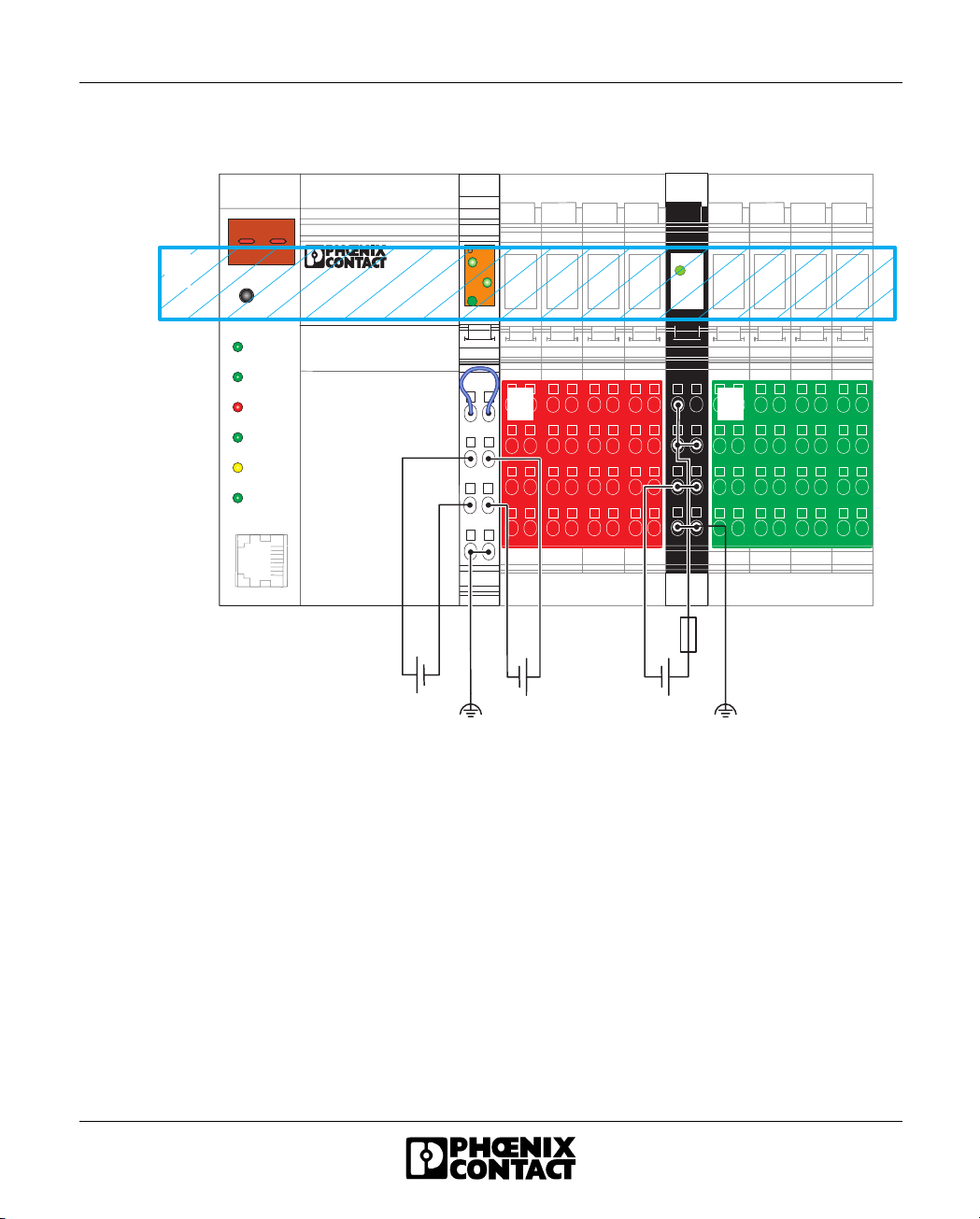
I/O supplies electrically isolated from one another
F L I L 2 4 B K - P A C I B I L 2 4 P W R I N
D O D I
FL IL 24 BK(-PAC)
U S
1
R E S E T
F L I L 2 4 B K - P A C
O r d . - N o . : 2 8 6 2 3 1 4
1 0 0
U M
U L
1 2 1 2 1 2 1 2
1 2
U M
P W R I N
1 2
1 2 1 2 1 2 1 2
F D
1
C O L
X M T
R C V
L I N K
1 0 / 1 0 0
1
1
1
1
1
1
1
1
2
2
2
2
3
4
-
+
U
B K
U
2
2
3
3
3
3
4
4
4
4
+
-
/ U
M 1
S 1
1
2
2
2
2
3
3
3
3
4
4
4
4
U
1
1
1
1
1
1
1
1
1
1
3
2
2
2
2
2
2
2
2
2
2
2
3
3
3
3
3
3
3
3
3
3
3
4
4
4
4
4
4
4
4
4
4
4
+
-
/ U
M 2
S 2
6 1 5 6 0 0 1 4
Figure 1-25 Structure of I/O supplies that are electrically isolated from one
another
Potentials within the station:
1 Bus logic of the station
2 I/O (outputs)
3 I/O (inputs)
615605 1-41
Page 56

FL IL 24 BK-PAC UM E
1.12 Diagnostic and status indicators
All modules are provided with LED diagnostic and status indicators for local error
diagnostics.
Diagnostics The diagnostic indicators (red/green) indicate the type and location of the error. The
module is functioning correctly if all of the green LEDs are on.
Once an error has been removed, the indicators immediately display the current
status.
Status The status indicators (yellow) display the status of the relevant inputs/outputs or the
connected device.
For information about the diagnostic and status indicators on each module,
please refer to the module-specific data sheet.
1.12.1 LEDs on the Ethernet Bus Coupler
1 0 0
F D
C O L
X M T
R C V
L I N K
U S
U M
U L
6 1 5 6 0 0 1 5
Figure 1-26 LEDs on the Ethernet bus coupler
1-42 615605
Page 57

Diagnostics The following states can be read on the bus coupler:
Table 1-14 Diagnostic LEDs of the bus coupler
Des. Color Status Meaning
Module Electronics
UL Green ON 24 V supply, 7 V communications power/interface supply present
OFF 24 V supply, 7 V communications power/interface supply not present
UM Green ON 24 V main circuit supply present
OFF 24 V main circuit supply not present
US Green ON 24 V segment supply present
OFF 24 V segment supply not present
Ethernet Port
100 Green ON Operation at 100 Mbps
OFF Operation at 10 Mbps (if LNK LED active)
FD Green ON Data transmission in full duplex mode
OFF Data transmission in half duplex mode (if LNK LED active)
COL Red ON Collision of data telegrams
OFF Transmission of telegrams without a collision (if LNK LED active)
XMT Green ON Data telegrams are being sent
OFF Data telegrams are not being sent
RCV Yellow ON Data telegrams are being received
OFF Data telegrams are not being received
LNK Green ON Physical network connection ready to operate
OFF Physical network connection interrupted or not present
FL IL 24 BK(-PAC)
615605 1-43
Page 58

FL IL 24 BK-PAC UM E
1.12.2 Indicators on the Supply Terminal
1
U S
U S
E
1
3
1 2
1 1
1 2
1 1
Figure 1-27 Possible indicators on supply terminals
(segment terminal with and without fuse and
power terminal)
Diagnostics The following states can be read from the supply terminals:
Table 1-15 Diagnostic LED on the power terminal
LED Color State Description of the LED States
UM
Green ON 24 V main circuit supply present
(2)
OFF Main circuit supply not present
Table 1-16 Diagnostic LED on the segment terminal
LED Color State Description of the LED States
US
Green ON 24 V segment circuit supply present
(1)
OFF Segment circuit supply not present
U S
U M
E
1 2
1 1
1
2
3
6 1 5 6 0 0 2 2
Table 1-17 Additional LED on supply terminals with fuse
LED Color State Description of the LED States
E
(3)
Red ON Fuse not present or blown
OFF Fuse OK
On modules with fuses, the green LED indicates that the main or segment voltage
is present at the line side of the fuse, meaning that if the green LED is on, there
is voltage on the line side of the fuse. If the red LED is also on, the voltage is not
present on the output side. Either no fuse is available or it is faulty.
1-44 615605
Page 59

1.12.3 Indicators on the Input/Output Modules
FL IL 24 BK(-PAC)
1
D
1
2
12121
2
D
1
2
3
4
1
2
2
1 2
1 2
1 2
1 2
1 1
1 1
1 1
1 1
Figure 1-28 I/O module indicators
Diagnostics The following states can be read from the I/O modules:
Table 1-18 Diagnostic LED of the I/O modules
LED Color State Description of the LED States
D
Green ON Local bus active
(1)
Flashing:
0.5 Hz
(slow)
2 Hz
(medium)
4 Hz
(fast)
OFF Communications power not present,
1 2
1 1
5 5 2 0 0 0 5 2
Communications power present, local bus not
active
Communications power present, I/O error
Communications power present,
module in front of the flashing module has failed
or the module itself is faulty;
Modules following the flashing module are not
part of the configuration frame.
local bus not active
Status The status of the input or output can be read on the relevant yellow LED:
615605 1-45
Page 60

FL IL 24 BK-PAC UM E
Table 1-19 Status LEDs of the I/O terminals
LED Color State Description of the LED States
1, 2, 3, 4
(2)
Assignment Between Status LED and Input/Output
For the assignment of a status LED and the corresponding input/output, please
refer to the module-specific data sheet.
Yellow ON Relevant input/output set
OFF Relevant input/output not set
1.12.4 Indicators on Other Inline Modules
For diagnostic and status indicators on other Inline modules (e.g., special function
modules or power modules), please refer to the module-specific data sheet.
1-46 615605
Page 61

FL IL 24 BK(-PAC)
1.13 Mounting/Removing Modules and Connecting
Cables
1.13.1 Installation Instructions
To ensure installation is carried out correctly, please read the "Installation
Instructions for the Electrical Engineer" supplied with the bus coupler.
Do not replace modules while the power is connected
Before removing or mounting a module, disconnect the power to the entire
station. Make sure the entire station is reassembled before switching the power
back on. Failure to observe this rule may damage the module.
1.13.2 Mounting and Removing Inline Modules
An Inline station can be set up by mounting the individual components side by side.
No tools are required. Mounting side by side automatically creates voltage and bus
signal connections (potential and data routing) between the individual station
components.
The modules are mounted perpendicular to the DIN rail. This ensures that they can
be easily mounted and removed even within limited space.
After a station has been set up, individual modules can be exchanged by pulling
them out or plugging them in. Tools are not required.
DIN rail All Inline modules are mounted on 35 mm (1.378 in.) standard DIN rails.
End clamp/CLIPFIX Mount end clamps on both sides of the Inline station. The end clamps ensure that
the Inline station is correctly assembled. End clamps fix the Inline station on both
sides and keep it from moving side to side on the DIN rail. Phoenix Contact
recommends using the CLIPFIX 35 (Order No. 30 22 21 8) or E/UK end clamps
(Order No. 12 01 44 2).
To remove the bus coupler, the left end clamp must be removed first.
615605 1-47
Page 62

FL IL 24 BK-PAC UM E
End plate An Ethernet Inline station must be terminated with an end plate. It has no electrical
function. It protects the station against ESD pulses and the user against dangerous
contact voltage. The end plate is supplied with the bus coupler and must not be
ordered separately.
1.13.3 Mounting
When mounting a module, proceed as follows (Figure 1-29):
• First snap on the electronics base, which is required for mounting the station,
perpendicular to the DIN rail (detail A).
Ensure that all featherkeys and keyways of adjacent modules are interlocked
(detail B).
The keyway/featherkey connection links adjacent modules and ensures safe
potential routing.
• Next, attach the connectors to the corresponding base.
First, place the front connector shaft latching in the front snap-on mechanism
(detail C).
Then press the top of the connector towards the base until it snaps into the
back snap-on mechanism (detail D).
The keyways of an electronics base do not continue when a connector has been
installed on the base. When snapping on an electronics base, there must be no
connector on the left-hand side of the base. If a connector is present, it will have
to be removed.
Use end clamps to fix the Inline station to the DIN rail (see Ordering Data).
1-48 615605
Page 63

FL IL 24 BK(-PAC)
A B
CD
6138A015
Figure 1-29 Snapping on a module
615605 1-49
Page 64

FL IL 24 BK-PAC UM E
1.13.4 Removing
When removing a module, proceed as follows (Figure 1-30):
• If there is a labeling field, remove it (A1 in detail A).
If a module has more than one connector, all of these must be removed. Below
is a description of how to remove a 2-slot module.
Lift the connector of the module to be removed by pressing on the back connector
shaft latching (A2 in detail A).
• Remove the connector (detail B).
• Remove the left-adjacent and right-adjacent connectors of the neighboring
modules (detail C). This prevents the potential routing featherkeys and the
keyway/featherkey connection from being damaged. You also have more
space available for accessing the module.
• Press the release mechanism, (D1 in detail D) and remove the electronics base
from the DIN rail by pulling the base straight back (D2 in detail D). If you have
not removed the connector of the next module on the left, remove it now in
order to protect the potential routing featherkeys and the keyway/featherkey
connection.
To remove the bus coupler, the left end clamp must be removed first.
1-50 615605
Page 65

FL IL 24 BK(-PAC)
A
A 2
B
A 1
D 1
C
D
D 1
Figure 1-30 Removing a module
Replacing a module If you want to replace a module within the Inline station, follow the removal
procedure described above. Do not snap the connector of the module directly to the
left back on yet. First, insert the base of the new module. Then reconnect all the
connectors.
Use end clamps to fix the Inline station to the DIN rail (see Ordering Data).
615605 1-51
D 2
6 1 5 6 0 0 0 7
Page 66

FL IL 24 BK-PAC UM E
1.13.5 Replacing a Fuse
The power and segment terminals are available with or without fuses.
For modules with fuses, the voltage presence and the fuse state are monitored and
indicated by diagnostic indicators.
If a fuse is not present or defective, you must insert or replace it.
Observe the following when replacing a fuse in order to protect your health
and the system.
1. Use the screwdriver carefully to avoid injury.
2. Lift the fuse out at the metal contact. Do not lift the fuse out at the glass part as
you may break it.
3. Carefully lift the fuse out at one side and remove it by hand. Make sure the fuse
does not fall into your system.
Follow these steps when replacing a fuse (see Figure 1-31):
• Lift the fuse lever (A).
• Insert the screwdriver behind a metal contact of the fuse (B).
• Carefully lift the metal contact of the fuse (C).
• Remove the fuse by hand (D).
• Insert a new fuse (E).
• Push the fuse lever down again until it clicks into place (F).
1-52 615605
Page 67

A B
FL IL 24 BK(-PAC)
C
E
Figure 1-31 Replacing a fuse
D
F
5 5 2 0 C 0 1 1
615605 1-53
Page 68

FL IL 24 BK-PAC UM E
1.14 Grounding an Inline Station
Ethernet bus coupler
and supply terminals
Required additional
grounding
All devices in an Inline station must be grounded so that any possible interference
is shielded and discharged to ground potential. A wire of at least 1.5 mm
2
(16 AWG)
must be used for grounding.
The bus coupler, power terminals, and segment terminals have FE springs (metal
clips) on the bottom of the electronics base. These springs create an electric
connection to the DIN rail. Use grounding terminal blocks to connect the DIN rail to
protective earth ground. The modules are grounded when they are snapped onto
the DIN rail.
In order to ensure reliable grounding even if the DIN rail is dirty or the metal clip has
been damaged, Phoenix Contact specifies that the bus coupler must also be
grounded via the FE terminal point (e.g., with the USLKG 5 universal ground
terminal block, Order No. 04 41 50 4, see Figure 1-32).
6 1 5 6 0 0 0 8
Figure 1-32 Additional grounding of the FL IL 24 BK(-PAC)
1-54 615605
Page 69

FL IL 24 BK(-PAC)
FE potential jumper The FE potential jumper (functional earth ground) runs from the bus coupler
through the entire Inline station. Ground the DIN rail. FE is grounded when a
module is snapped onto the DIN rail correctly. If supply terminals are part of the
station, the FE potential jumper is also connected with the grounded DIN rail.
The function of FE is to discharge interference. It does not provide shock
protection for people.
Low-level signal The other Inline low-level signal modules are automatically grounded via the FE
potential jumper when they are mounted adjacent to other modules.
Power level The FE potential jumper is also connected to the power modules.
615605 1-55
Page 70

FL IL 24 BK-PAC UM E
1.14.1 Shielding an Inline Station
Shielding is used to reduce the effects of interference on the system.
In the Inline station, the Ethernet cable and the module connecting cables for
analog signals are shielded.
Observe the following when using shielded cables:
– Fasten the shielding so that as much of the braided shield as possible is held
underneath the clamp of the shield connection.
– Make sure there is good contact between the connector and module.
– Do not damage or squeeze the wires. Do not strip off the wires too far.
– Make a clean wire connection.
1.14.2 Shielding Analog Sensors and Actuators
– For maximum noise immunity, always connect analog sensors and actuators
using shielded, twisted-pair cables.
– Connect the shielding to the shield connector. The method for connecting the
shielding is described in Section 1.15.2, "Connecting Shielded Cables Using
the Shield Connector".
– Analog input and output modules require different shielding connections. The
cable lengths must also be considered.
.
Table 1-20 Overview: shield connection of analog sensors/actuators
Module Type Connection to the Module Cable Length Connection to the Sensor/
Actuator
Analog input module
IB IL AI 2/SF
Analog output module
IB IL AO ...
1-56 615605
Within the module, ground is
connected to FE via an RC
element.
Via shield connection clamp
directly to FE
< 10 m
(32.81 ft.)
> 10 m
(32.81 ft.)
< 10 m
(32.81 ft.)
> 10 m
(32.81 ft.)
–
Connect the sensor directly to PE
–
Isolate the actuator with an RC
element and connect it to PE
Page 71

FL IL 24 BK(-PAC)
1.14.2.1 Connecting an IB IL 24 AI 2/SF Analog Input Module
• Connect the shielding to the shield connector (see Section 1.15.2, "Connecting
Shielded Cables Using the Shield Connector").
• When connecting the sensor shielding with FE potential, ensure a large surface
connection.
Within the module, ground is connected to FE via an RC element.
A
Figure 1-33 Connection of analog sensors, signal cables > 10 m (32.81 ft.)
A Module side
B Sensor side
If you want to use both channels of the IB IL AI 2/SF module, there are different
ways of connecting the shielding, depending on the cross-section.
1 Use a multi-wire cable for the connection of both sensors and connect the
shielding to the shield connector as described above.
2 Use a thin cable for the connection of each sensor and connect the shielding
of both cables together to the shield connector.
3 Use the standard connector (IB IL SCN-8; without shield connector). Twist the
braided shield of each cable and place it on one of the terminal points to be
used for FE connection.
You should only use this option if the cross-section is too large and the first two
methods are not possible.
B
5 5 2 0 0 0 4 3
615605 1-57
Page 72

FL IL 24 BK-PAC UM E
1.14.2.2 Connecting an Analog Output Module IB IL AO ...
– Connect the shielding via the shield connector (see Section 1.15.2,
"Connecting Shielded Cables Using the Shield Connector").
– When connecting the shielding with the FE potential, ensure a large surface
connection.
Danger of creating ground loops
– The shielding must only be directly connected to ground potential at one
point.
– For cable lengths exceeding 10 meters (32.81 ft.) the actuator side should
always be isolated by means of an RC element.
The capacitor C should typically have values of 1 nF to 15 nF. The resistor R
should be at least 10 MΩ.
A
Figure 1-34 Connection of actuators, signal cables > 10 m (32.81 ft.)
A Module side
B Actuator side
B
R C
5 5 2 0 0 0 4 2
1-58 615605
Page 73

FL IL 24 BK(-PAC)
1.15 Connecting Cables
Both shielded and unshielded cables are used in a station.
The cables for the I/O devices and supply voltages are connected using the spring-
cage connection method. This means that signals up to 250 V AC/DC and 5 A with
a conductor cross section of 0.2 mm
connected.
The Ethernet cable is connected via an 8-pos. RJ45 connector.
1.15.1 Connecting Unshielded Cables
2
through 1.5 mm2 (AWG 25 - 16) can be
i
g
i
t
a
l
I
n
p
1
A
B
6138A016
Figure 1-35 Connecting unshielded cables
615605 1-59
Page 74

FL IL 24 BK-PAC UM E
Wire the connectors as required for your application.
For connector assignment, please refer to the appropriate module-specific data
sheet.
When wiring, proceed as follows:
• Strip 8 mm (0.315 in.) off the cable. Fieldbus coupler and Inline wiring is
normally done without ferrules. However, it is possible to use ferrules. If using
ferrules, make sure they are properly crimped.
• Push a screwdriver into the slot of the appropriate terminal point
(Figure 1-35, detail 1), so that you can insert the wire into the spring opening.
Phoenix Contact recommends using a SFZ 1 - 0,6 x 3,5 screwdriver (Order
No. 12 04 51 7; see Phoenix Contact "CLIPLINE" catalog).
• Insert the wire (Figure 1-35, detail B). Remove the screwdriver from the
opening. This clamps the wire.
• After installation, the wires and the terminal points should be labeled.
1-60 615605
Page 75

FL IL 24 BK(-PAC)
1.15.2 Connecting Shielded Cables Using the Shield
Connector
1
3
5
1 5 m m
( 0 . 5 9 1 " )
a
2
8 m m
( 0 . 3 1 5 " )
4
6
5 9 8 1 A 0 2 3
Figure 1-36 Connecting the shield to the shield connector
615605 1-61
Page 76
FL IL 24 BK-PAC UM E
This section describes the connection of a shielded cable, using an "analog cable"
as an example.
Connection should be carried out as follows:
Stripping cables • Strip the outer cable sheath to the desired length (a). (1)
The desired length (a) depends on the connection position of the wires and
whether there should be a large or a small space between the connection point
and the shield connection.
• Shorten the braided shield to 15 mm (0.591 in.). (1)
• Fold the braided shield back over the outer sheath. (2)
• Remove the protective foil.
• Strip 8 mm (0.315 in.) off the wires. (2)
Inline wiring is normally done without ferrules. However, it is possible to use
ferrules. If using ferrules, make sure they are properly crimped.
Wiring the connectors • Push a screwdriver into the slot of the appropriate terminal point (Figure 1-35
on page 1-59, detail 1), so that you can insert the wire into the spring opening.
Phoenix Contact recommends using a SFZ 1 - 0,6 x 3,5 screwdriver
(Order No. 12 04 51 7; see Phoenix Contact "CLIPLINE" catalog).
• Insert the wire (Figure 1-35 on page 1-59, detail 2). Remove the screwdriver
from the opening. This clamps the wire.
For connector assignment, please refer to the appropriate module-specific data
sheet.
Connecting the shield • Open the shield connector. (3)
• Check the direction of the shield connection clamp in the shield connector (see
Figure 1-37).
• Place the cable with the folded braided shield in the shield connector. (4)
• Close the shield connector. (5)
• Fasten the screws on the shield connector using a screwdriver. (6)
1-62 615605
Page 77

FL IL 24 BK(-PAC)
1
1
4
1
Shield connection
clamp
2
1
5
1
Figure 1-37 Shield connection clamp alignment
The shield connection clamp (a in Figure 1-37, detail 2) in the shield connector can
be used in various ways depending on the cross section of the cable. For thicker
cables, the dip in the clamp must be turned away from the cable (Figure 1-37,
detail 2). For thinner cables, the dip in the clamp is turned towards the cable
(Figure 1-37, detail 6).
If you need to change the direction of the shield connection clamp, proceed as
shown in Figure 1-37:
• Open the shield connector housing (1).
• The shield connection is delivered with the clamp positioned for connecting
thicker cables (2).
• Remove the clamp (3), turn it to suit the cross-section of the cable (4), then
reinsert the clamp (5).
• Figure 6 shows the position of the clamp for a thin cable.
a
3
1
6
1
5 5 2 0 A 0 6 8
615605 1-63
Page 78

FL IL 24 BK-PAC UM E
1.16 Connecting the Voltage Supply
To operate a station you must provide the supply voltage for the bus coupler, logic
of the modules, and the sensors and actuators.
The voltage supplies are connected using unshielded cables (see Section 1.15.1).
For the connector assignment of the supply voltage connections, please refer to
the module-specific data sheets for power and segment terminals.
Do not replace terminals while the power is connected
Before removing or mounting a module, disconnect the power to the entire
station. Make sure the entire station is reassembled before switching the power
back on.
1.16.1 Power Terminal Supply
Apart from supplying the I/O voltage at the Fieldbus coupler, it is also possible to
provide the voltage using a power terminal.
U
M
U
S
Electrical isolation You can create a new potential area through the power terminal.
Voltage areas Power terminals can be used to create substations with different voltage areas.
1-64 615605
24 V Main Circuit Supply
The main power is reintroduced at the power terminal.
24 V Segment Circuit Supply
The segment voltage can be supplied at the power terminal or generated from the
main power. Install a jumper or create a segment circuit using a switch to tap the
voltage U
Depending on the power terminal, it is possible to work with 24 V DC, 120 V AC or
230 V AC.
from the main circuit UM.
S
Page 79

FL IL 24 BK(-PAC)
Use appropriate power terminals for different voltage areas
To use different voltage areas within a station, a new power terminal must be
used for each area.
Dangerous voltage
When the power terminal is removed, the metal contacts are freely accessible.
With 120 V or 230 V power terminals, it should be assumed that dangerous
voltage is present. You must disconnect power to the station before removing
a terminal.
If these instructions are not followed, there is a danger of damage to health
or even of a life-threatening injury.
1.16.2 Provision of the Segment Voltage Supply at Power
Terminals
You cannot provide voltage at the segment terminal.
A segment terminal can be used to create a new partial circuit (segment circuit)
within the main circuit. This segment circuit permits the separate supply of power
outputs and digital sensors and actuators.
You can use a jumper to tap the segment voltage from the main circuit. If you use
a switch, you can control the segment circuit externally.
You can create a protected segment circuit without additional wiring by means of a
segment terminal with a fuse.
1.16.3 Demands on the Power Supply Units
Use power supply units with safe isolation
Only use power supply units that ensure safe isolation between the primary and
secondary circuits according to EN 50178.
For additional voltage supply requirements, please refer to the data sheets for the
segment and power terminals.
615605 1-65
Page 80

FL IL 24 BK-PAC UM E
1.17 Connecting Sensors and Actuators
Sensors and actuators are connected using connectors. Each module-specific data
sheet indicates the connector(s) to be used for that specific module.
Connect the unshielded cable as described in Section 1.15.1 on page 1-59 and the
shielded cable as described in Section 1.15.2 on page 1-61.
1.17.1 Connection Methods for Sensors and Actuators
Most of the digital I/O modules in the Inline product range permit the connection of
sensors and actuators in 2, 3 and 4-wire technology.
Because of the different types of connectors, a single connector can support the
following connection methods:
– 2 sensors or actuators in 2, 3 or 4-wire technology
– 4 sensors or actuators in 2 or 3-wire technology
– 2 sensors or actuators in 2 or 3-wire technology with shield
(for analog sensors or actuators)
When connecting analog devices, please refer to the module-specific data
sheets, as the connection method for analog devices differs from that for digital
devices.
1-66 615605
Page 81

1.17.2 Connection Examples for Digital I/O Modules
Various connection options are described below using 24 V DC modules as an
example. For the 120 V/230 V AC area, the data changes accordingly. A connection
example is given in each module-specific data sheet.
Table 1-21 Overview of the connections used for digital input modules
FL IL 24 BK(-PAC)
Connection Representation in
2-wire 3-wire 4-wire
the Figure
Sensor signal IN IN X X X
Sensor supply US / U
M
US (+24 V) X X X
Ground GND GND (⊥) – XX
Ground/FE shielding
––X
FE ( )
XUsed
– Not used
Table 1-22 Overview of the connections used for digital output modules
Connection Representation in
2-wire 3-wire 4-wire
the Figure
Actuator signal OUT OUT X X X
Actuator supply U
S
US (+24 V) ––X
Ground GND GND (⊥) XXX
Ground/FE shielding FE ( ) – XX
XUsed
– Not used
In the following figures US designates the supply voltage. Depending on which
potential jumper is accessed, the supply voltage is either the main voltage U
the segment voltage U
615605 1-67
.
S
or
M
Page 82

FL IL 24 BK-PAC UM E
2-wire technology
Different Connection Methods for Sensors and Actuators
A
I N 1
U
S
G N D
F E
I N 1
+ 2 4 V
B
O U T 1
U
S
G N D
F E
O U T 1
5 5 2 0 0 0 2 7
Figure 1-38 2-wire termination for digital devices
Sensor Figure 1-38, detail A, shows the connection of a 2-wire sensor. The sensor signal
is carried to terminal point IN1. The sensor is supplied from the voltage U
.
S
Actuator Figure 1-38, detail B, shows the connection of an actuator. The actuator is supplied
through output OUT1. The load is switched directly by the output.
The maximum current carrying capacity of the output must not be exceeded (see
the module-specific data sheet).
1-68 615605
Page 83

3-wire technology
FL IL 24 BK(-PAC)
A
I N 1
U
S
G N D
I N 2
U
S
I N 1
+ 2 4 V
G N D
B
O U T 1
G N D
F E
O U T 2
G N D
F E
O U T 1
I N 2
+ 2 4 V
O U T 2
5 5 2 0 0 0 3 8
Figure 1-39 3-wire termination for digital devices
Sensor Figure 1-39, detail A, shows the connection of a 3-wire sensor. The sensor signal
is carried to terminal point IN1 (IN2). The sensor is supplied via terminal points U
and GND.
Actuator Figure 1-39, detail B, shows the connection of a shielded actuator. The actuator is
supplied through output OUT1 (OUT2). The load is switched directly by the output.
S
The maximum current carrying capacity of the output must not be exceeded (see
the module-specific data sheet).
615605 1-69
Page 84

FL IL 24 BK-PAC UM E
4-wire technology
A
I N 1
U
S
G N D
F E
I N 1
+ 2 4 V
B
O U T 1
U
S
G N D
F E
+ 2 4 V
O U T 1
5 5 2 0 0 0 3 7
Figure 1-40 4-wire termination for digital devices
Sensor Figure 1-40, detail A, shows the connection of a shielded 4-wire sensor. The sensor
signal is carried to terminal point IN1. The sensor is supplied via terminal points U
and GND. The sensor is grounded via the FE terminal point.
Actuator Figure 1-40, detail B, shows the connection of a shielded actuator. The provision of
the supply voltage U
means that even actuators that require a separate 24 V
S
supply can be connected directly to the terminal.
S
The maximum current carrying capacity of the output must not be exceeded (see
the module-specific data sheet).
1-70 615605
Page 85

Section 2
This section provides information about
– startup
– assigning IP parameters
– the Management Information Base (MIB)
Startup/Operation ............................................................................................................. 2-3
2.1 Default Upon Delivery/Default Settings .................................................. 2-3
2.2 Firmware Start........................................................................................ 2-3
2.3 Transmitting BootP Requests.................................................................2-4
2.4 Assigning an IP Address Using the Factory Manager............................ 2-4
2.4.1 BootP.......................................................................................2-4
2.5 Manual Addition of Devices Using The Factory Manager ...................... 2-5
2.6 Selecting IP Addresses ..........................................................................2-5
2.6.1 Possible Address Combinations ..............................................2-7
2.6.2 Subnet Masks..........................................................................2-8
2.6.3 Structure of the Subnet Mask .................................................. 2-8
2.7 Web-Based Management.....................................................................2-10
2.7.1 Calling Web-Based Management (WBM).............................. 2-10
2.7.2 Structure of the Web Pages...................................................2-11
2.7.3 Layout of the Web Pages ......................................................2-11
2.7.4 Password Protection.............................................................. 2-12
2.7.5 Process Data Access Via XML.............................................. 2-12
2.8 Firmware Update.................................................................................. 2-17
2.8.1 Firmware Update Using The Factory Manager......................2-17
2.9 Firmware Update Using Web-Based Management (WBM)
Without Factory Manager.....................................................................2-19
2.9.1 Trap Generation..................................................................... 2-19
2.9.2 Representation of Traps in the Factory Manager .................. 2-19
2.9.3 FL IL 24 BK(-PAC)Traps........................................................2-20
2.9.4 Defining the Trap Manager ....................................................2-20
2.10 Factory Line I/O Configurator ...............................................................2-21
2.10.1 Factory Line I/O Browser....................................................... 2-21
2.10.2 OPC Configurator ..................................................................2-22
2.11 Management Information Base - MIB................................................... 2-24
2.11.1 Standard MIBs: ...................................................................... 2-24
615605 2-1
Page 86

FL IL 24 BK-PAC UM E
2.12 Interface Group (1.3.6.1.2.1.2) .............................................................2-25
2.12.1 Private MIBs ..........................................................................2-30
2.13 Meaning of the 7-Segment Display ......................................................2-44
2-2 615605
Page 87

2 Startup/Operation
2.1 Default Upon Delivery/Default Settings
By default upon delivery the following functions and properties are available:
– The password is "private".
– The bus coupler has no valid IP parameters:
IP address: 0.0.0.0
Subnet mask: 0.0.0.0
Gateway: 0.0.0.0
– Plug & play mode activated
– Expert mode inactive
– System description: Ethernet bus coupler
System contact: unknown
System name: FL IL 24 BK
System location: unknown
– HW watchdog activated (default parameter: 0x00000001).
– No INTERBUS configuration stored. All entries set to 0x0000.
– Fault response mode: 1
– Protocol switch: 0
– Watchdog timeout: 500 ms
Startup/Operation
2.2 Firmware Start
The firmware is started after the device has been connected to the power supply or
the reset key has been pressed. The following sequence is displayed (see also
"Startup Behavior of the Bus Coupler" on page 3-8):
Table 2-1 Sequence displayed after the device is switched on
Display Meaning
01 Boot loader is started, BootP requests are transmitted
bo Firmware is extracted
02 Firmware is started
PP
--
615605 2-3
Plug & play mode activated or
operation
Page 88

FL IL 24 BK-PAC UM E
2.3 Transmitting BootP Requests
Initial Startup:
During initial startup, the device transmits BootP requests without interruption until
it receives a valid IP address. The requests are transmitted at varying intervals
(2 s, 4 s, 8 s, 2 s, 4 s, etc.) so that the network is not loaded unnecessarily. If valid
IP parameters are received, they are saved as configuration data by the device.
Restart:
If the device already has valid configuration data, it only transmits three more BootP
requests upon a restart. If it receives a BootP reply, the new parameters are saved.
If the device does not receive a reply, it starts with the previous configuration.
If only the tftp parameters are modified (see "Firmware Update" on page 2-17)
for the existing configuration and the IP parameters remain the same, e.g., using
firmware with a new file name, the modifications to the configuration only take
effect when the software update flag is enabled on the device web page or via
SNMP.
2.4 Assigning an IP Address Using the Factory Manager
Alternatively, the IP address can be entered via any BootP server.
There are two options available when assigning the IP address: reading the MAC
address via BootP or manually entering the MAC address in the Add New Ethernet
Device dialog box in the Factory Manager.
2.4.1 BootP
– Ensure that the network scanner and the BootP server have been
started.
– Connect the device to the network and the supply voltage.
2-4 615605
Page 89

Startup/Operation
– The BootP request for the new device triggered by the device restart/reset
appears in the Factory Manager message window. Select the relevant
message.
– Click with the right mouse button on the BootP message for the device or on
.
– Enter the relevant data in the Add New Ethernet Device dialog box (see 2.5).
– Save the configuration settings and restart the device (reset key or power up).
If the device is being started for the first time, it is then automatically booted with
the specified configuration. If the device is not being started for the first time, save
the configuration and restart the device (reset key or power up). The device now
transmits another BootP request and receives the specified IP parameters from
the BootP server/Factory Manager.
2.5 Manual Addition of Devices Using The Factory Manager
– Open the Add New Ethernet Device dialog box by clicking on , by
selecting "Add Device" from the Device View context menu or by using the
Ctrl+A key combination.
– Enter the desired data under "Description" and "TCP/IP Address".
– Activate the "BootP Parameter" by selecting "Reply on BootP Requests".
– Enter the MAC address. It can be found on the sticker on the front of the
housing.
– Save the configuration settings and restart the device (reset key or power up).
The device now transmits another BootP request and receives the specified IP
parameters from the BootP server.
2.6 Selecting IP Addresses
The IP address is a 32-bit address, which consists of a network part and a user part.
The network part consists of the network class and the network address.
There are currently five defined network classes; classes A, B, and C are used in
modern applications, while classes D and E are hardly ever used. It is therefore
usually sufficient if a network device only "recognizes" classes A, B, and C.
615605 2-5
Page 90

FL IL 24 BK-PAC UM E
With binary representation of the IP address the network class is represented by
the first bits. The key factor is the number of "ones" before the first "zero". The
assignment of classes is shown in the following table. The empty cells in the table
are not relevant to the network class and are already used for the network address.
Bit 1 Bit 2 Bit 3 Bit 4 Bit 5
Class A 0
Class B 10
Class C 110
Class D 1110
Class E 11110
The bits for the network class are followed by those for the network address and
user address. Depending on the network class, a different number of bits is
available, both for the network address (network ID) and the user address (host ID).
Network ID Host ID
Class A 7 bits 24 bits
Class B 14 bits 16 bits
Class C 21 bits 8 bits
Class D 28-bit multicast identifier
Class E 27 bits (reserved)
IP addresses can be represented in decimal, octal or hexadecimal notation. In
decimal notation, bytes are separated by dots (dotted decimal notation) to show the
logical grouping of the individual bytes.
The decimal points do not divide the address into a network and user address.
Only the value of the first bits (before the first "zero") specifies the network class
and the number of remaining bits in the address.
2-6 615605
Page 91

2.6.1 Possible Address Combinations
7 b i t s 2 4 b i t s
Startup/Operation
C l a s s A
0 . 0 . 0 . 0 - 1 2 7 . 2 5 5 . 2 5 5 . 2 5 5
C l a s s B
1 2 8 . 0 . 0 . 0 - 1 9 1 . 2 5 5 . 2 5 5 . 2 5 5
C l a s s C
1 9 2 . 0 . 0 . 0 - 2 2 3 . 2 5 5 . 2 5 5 . 2 5 5
C l a s s D
2 2 4 . 0 . 0 . 0 - 2 3 9 . 2 5 5 . 2 5 5 . 2 5 5
C l a s s E
2 4 0 . 0 . 0 . 0 - 2 4 7 . 2 5 5 . 2 5 5 . 2 5 5
0
1
N e t w o r k I D H o s t I D
1 4 b i t s 1 6 b i t s
0
111
N e t w o r k I D
0
0
1111
2 1 b i t s 8 b i t s
N e t w o r k I D
I d e n t i f i e r f o r m u l t i c a s t g r o u p
R e s e r v e d f o r f u t u r e a p p l i c a t i o n s
0
11
H o s t I D
H o s t I D
2 8 b i t s
2 7 b i t s
Figure 2-1 Structure of IP addresses
Special IP Addresses for Special Applications
Certain IP addresses are reserved for special functions. The following addresses
should not be used as standard IP addresses.
127.x.x.x Addresses
The class A network address "127" is reserved for a loop-back function on all PCs,
regardless of the network class. This loop-back function may only be used on
networked PCs for internal test purposes.
If a telegram is addressed to a PC with the value 127 in the first byte, the receiver
immediately sends the telegram back to the transmitter.
The correct installation and configuration of the TCP/IP software, for example, can
be checked in this way.
As the first and second layers of the ISO/OSI reference model are not included in
the test, complete testing should be carried out separately using the ping function.
615605 2-7
Page 92

FL IL 24 BK-PAC UM E
Value 255 in the Byte
Value 255 is defined as a broadcast address. The telegram is sent to all the PCs
that are in the same part of the network. Examples: 004.255.255.255, 198.2.7.255
or 255.255.255.255 (all the PCs in all the networks). If the network is divided into
subnetworks, the subnet masks must be observed during calculation, otherwise
some devices may be omitted.
0.x.x.x Addresses
Value 0 is the ID of the specific network. If the IP address starts with a zero, the
receiver is in the same network. Example: 0.2.1.1 refers to device 2.1.1 in this
network.
The zero previously signified the broadcast address. If older devices are used,
unauthorized broadcast and complete overload of the entire network (broadcast
storm) may occur when using the IP address 0.x.x.x.
2.6.2 Subnet Masks
Routers and gateways divide large networks into several subnetworks. The
IP addresses for individual devices are assigned to specific subnetworks by the
subnet mask. The network part of an IP address is not modified by the subnet
mask. An extended IP address is generated from the user address and subnet
mask. Because the masked subnetwork is only recognized by the local PCs, this
extended IP address appears as a standard IP address to all the other devices.
2.6.3 Structure of the Subnet Mask
The subnet mask always contains the same number of bits as an IP address. The
subnet mask has the same number of bits (in the same position) set to "one", which
is reflected in the IP address for the network class.
Example: An IP address from class A contains a 1-byte network address and a
3-byte PC address. Therefore, the first byte of the subnet mask may only contain
"ones".
The remaining bits (three bytes) then contain the address of the subnetwork and
the PC. The extended IP address is created when the bits of the IP address and the
bits of the subnet mask are ANDed. Because the subnetwork is only recognized by
local devices, the corresponding IP address appears as a "normal" IP address to all
the other devices.
2-8 615605
Page 93

Startup/Operation
Application
If ANDing of the address bits gives the local network address and the local
subnetwork address, the device is located in the local network. If ANDing gives a
different result, the data telegram is sent to the subnetwork router.
Example for a class B subnet mask:
D e c i m a l n o t a t i o n :
B i n a r y n o t a t i o n :
2 5 5 . 2 5 5 . 1 9 2 . 0
1 1 1 1 1 1 1 1 . 1 1 1 1 1 1 1 1 . 1 1 0 0 0 0 0 0 . 0 0 0 0 0 0 0 0
S u b n e t m a s k b i t s
C l a s s B
Using this subnet mask, the TCP/IP protocol software differentiates between the
devices that are connected to the local subnetwork and the devices that are located
in other subnetworks.
Example: Device 1 wants to establish a connection to device 2 using the above
subnet mask. Device 2 has IP address 59.EA.55.32.
IP address representation for device 2:
H e x a d e c i m a l n o t a t i o n :
B i n a r y n o t a t i o n :
The individual subnet mask and the IP address for device 2 are then ANDed bit by
bit by the software to determine whether device 2 is located in the local subnetwork.
ANDing the subnet mask and IP address for device 2:
S u b n e t m a s k :
5 9 . E A . 5 5 . 3 2
0 1 0 1 1 0 0 1 . 1 1 1 0 1 0 1 0 . 0 1 0 1 0 1 0 1 . 0 0 1 1 0 0 1 0
1 1 1 1 1 1 1 1 . 1 1 1 1 1 1 1 1 . 1 1 0 0 0 0 0 0 . 0 0 0 0 0 0 0 0
A N D
I P a d d r e s s :
0 1 0 1 1 0 0 1 . 1 1 1 0 1 0 1 0 . 0 1 0 1 0 1 0 1 . 0 0 1 1 0 0 1 0
R e s u l t a f t e r A N D i n g :
0 1 0 1 1 0 0 1 . 1 1 1 0 1 0 1 0 . 0 1 0 0 0 0 0 0 . 0 0 0 0 0 0 0 0
S u b n e t w o r k
After ANDing, the software determines that the relevant subnetwork (01) does not
correspond to the local subnetwork (11) and the data telegram is forwarded to a
subnetwork router.
615605 2-9
Page 94

FL IL 24 BK-PAC UM E
2.7 Web-Based Management
The FL IL 24 BK(-PAC) has a web server, which generates the required pages for
web-based management and, depending on the requirements of the user, sends
them to the "Factory Manager" or a standard web browser.
Web-based management can be used to access static information (e.g., technical
data, MAC address) or dynamic information (e.g., IP address, status information) or
to change the configuration (password-protected).
2.7.1 Calling Web-Based Management (WBM)
The FL IL 24 BK-PAC web server can be addressed using the IP address if
configured correspondingly.
The bus coupler homepage is accessed by entering the URL "http://ip-address".
Example: http://192.168.2.81
Figure 2-2 WBM homepage
2-10 615605
Page 95

Startup/Operation
2.7.2 Structure of the Web Pages
The Ethernet bus coupler pages are divided into two parts, with the selection menu
and the relevant submenus on the left-hand side, and the corresponding
information displayed on the right-hand side. Static and dynamic information about
the bus coupler can be found in the following menus.
2.7.3 Layout of the Web Pages
F L I L 2 4 B K - P A C
G e n e r a l I n s t r u c t i o n s
I n f o r m a t i o n
D e v i c e I n f o r m a t i o n
G e n e r a l
T e c h n i c a l D a t a
H a r d w a r e I n s t a l l a t i o n
L o c a l D i a g n o s t i c s
D e v i c e C o n f i g u r a t i o n
I P C o n f i g u r a t i o n
S N M P C o n f i g u r a t i o n
S o f t w a r e U p d a t e
C h a n g e P a s s w o r d
W a t c h d o g ( H a r d w a r e )
I n l i n e S t a t i o n
S e r v i c e s
P r o c e s s D a t a M o n i t o r i n g ( P r o c e s s D a t a W a t c h d o g )
R e m o t e D i a g n o s t i c s
B u s C o n f i g u r a t i o n
E v e n t T a b l e
6 1 5 5 0 0 4
P C P C o n f i g u r a t i o n
615605 2-11
Page 96

FL IL 24 BK-PAC UM E
2.7.4 Password Protection
The bus coupler is protected by two passwords (case-sensitive). The password for
read access is "public", while the password for read and write access is "private".
All status changes to the bus coupler are only possible after the password for read
and write access has been entered. The password can be changed at any time.
Your unique password must be between four and twelve characters long.
If you forget the password, the device can be re-enabled by Phoenix Contact.
Ensure you have the exact device designation and serial number ready when you
call the telephone number indicated on the last page.
2.7.5 Process Data Access Via XML
The integrated FL IL 24 BK-PAC web server can be used to access the process
data of the connected Inline terminals using a web page in XML format.
Use a standard web browser to access the web pages. Enter the address in the
following format in the address line of the browser to call the XML pages containing
the process data: "http:// <IP-Adresse>/processdata.xml".
2.7.5.1 Structure of the XML Files
The XML file comprises different data areas:
IL_STATION Frame for the entire XML file. The obligatory elements of this frame are
IL_BUS_TERMINAL and IL_BUS.
IL_BUS_TERMINAL This data area contains information on the entire Inline station (bus coupler and all
connected terminals). This area includes: TERMINAL_TYPE, module NAME,
IP_ADDRESS, the number of connected terminals MODULE_NUMBER, the
INTERBUS diagnostic register DIAGNOSTIC_STATUS_REGISTER, and the
INTERBUS status register DIAGNOSTIC_PARAMETER_REGISTER.
TERMINAL_TYPE This area contains the module designation, i.e., always FL IL 24 BK(-PAC).
NAME Contains user-specific station names. The station name can be modified via SNMP
or WBM.
IP_ADDRESS Contains the station IP address.
MODULE_NUMBER Contains the number of connected Inline terminals. In the event of a bus error the
number of the last known operable configuration is specified.
2-12 615605
Page 97

Startup/Operation
DIAGNOSTIC_STATUS
_REGISTER
IL_BUS Frame for the connected Inline terminals.
IL_MODULE Frame for the data of individual Inline terminals. The terminals are numbered from
MODULE_TYPE Contains the module type, e.g., DI, DO, DIO, AI, AO, AIO, and PCP.
PD_CHANNELS Number of process data channels of an Inline terminal. With digital terminals the
PD_WORDS Number of process data words of an Inline terminal. Note that analog terminals
PD_IN This area is used by all terminals that use input data. The number of process data
Contains the INTERBUS status, indicated by all the bits in the diagnostic status
register. A detailed description can be found in the diagnostic parameter register.
The diagnostic parameter register is always re-written if an error bit is set.
one to 63, maximum.
number of channels is equal to the number of supported bits. With other modules
the number of process data words is indicated. Example: An AO 2 has two process
data channels and a DO 8 has eight bits and eight process data channels.
always have the same number of output and input data words. An AO 2 also has
two input channels and an AI 2 also has two output channels.
words depends on the terminal type.
Example:
a) Inline terminal with two active inputs
<IL_MODULE number="1">
<MODULE_TYPE>DI</MODULE_TYPE>
<PD_CHANNELS>2</PD_CHANNELS>
<PD_WORDS>1</PD_WORDS>
<PD_IN word="1">3</PD_IN>
</IL_MODULE>
b) Inline terminal with two digital inputs; only the second input is active
<IL_MODULE number="3">
<MODULE_TYPE>DI</MODULE_TYPE>
<PD_CHANNELS>2</PD_CHANNELS>
<PD_WORDS>1</PD_WORDS>
<PD_IN word="1">2</PD_IN>
</IL_MODULE>
c) Inline terminal with 16 digital inputs; inputs 13 and 14 are active
615605 2-13
Page 98

FL IL 24 BK-PAC UM E
PD_OUT This area is used by all terminals with output data. The use of bits is identical to the
<IL_MODULE number="7">
<MODULE_TYPE>DI</MODULE_TYPE>
<PD_CHANNELS>16</PD_CHANNELS>
<PD_WORDS>1</PD_WORDS>
<PD_IN word="1">12288</PD_IN>
</IL_MODULE>
12
The inputs data word returns the value 12288 (2
+ 213).
d) Inline terminal with two analog inputs; only the first channel (14970) is active
<IL_MODULE number="10">
<MODULE_TYPE>AI</MODULE_TYPE>
<PD_CHANNELS>2</PD_CHANNELS>
<PD_WORDS>2</PD_WORDS>
<PD_IN word="1">14970</PD_IN>
<PD_IN word="2">8</PD_IN>
<PD_OUT word="1">0</PD_OUT>
<PD_OUT word="2">0</PD_OUT>
</IL_MODULE>
use of "PD_IN".
2.7.5.2 Validity of Data
The validity of data is identical to the validity via DDI or OPC access.
2.7.5.3 Error in the Inline Station
If the FL IL 24 BK(-PAC) is not able to configure the connected Inline terminals
correctly, error code "82" is displayed. The process data is then listed in the XML
file as follows:
<?xml version="1.0" encoding="ISO-8859-1"?>
<!DOCTYPE IL_STATION SYSTEM "processdata.dtd">
<IL_STATION>
<IL_BUS_TERMINAL>
<TERMINAL_TYPE>FL IL 24 BK-PAC</TERMINAL_TYPE>
<NAME>FL IL 24 BK-PAC</NAME>
<IP_ADDRESS>172.16.27.37</IP_ADDRESS>
<MODULE_NUMBER>0</MODULE_NUMBER>
<DIAGNOSTIC_STATUS_REGISTER>132
</DIAGNOSTIC_STATUS_REGISTER>
<DIAGNOSTIC_PARAMETER_REGISTER>65535</
DIAGNOSTIC_PARAMETER_REGISTER>
</IL_BUS_TERMINAL>
<IL_BUS>
</IL_BUS>
</IL_STATION>
2-14 615605
Page 99

Startup/Operation
The values of the diagnostic status register and the diagnostic parameter register
indicate the error cause. The number of the connected terminals is "zero", which
means that the "IL_BUS" area is empty.
In the event of a bus error "bF" is displayed. The process data is invalid because
only internal values but no values on INTERBUS are indicated. The status is shown
in the diagnostic register.
To ensure that valid data is shown, the diagnostic register must also always be
scanned. The same behavior will occur if a wrong configuration is connected. In this
case INTERBUS is not running and only internal values can be read in the XML file.
In the event of an I/O error all data is valid, except for the data of the faulty terminal.
615605 2-15
Page 100

FL IL 24 BK-PAC UM E
Figure 2-3 Screenshot of the XML data
2-16 615605
 Loading...