

Page 1
EV Charge Control
Standard-compliant control of the
Control Pilot and Proximity Plug
interfaces between the electric
vehicle and charging station
User manual
Page 2

User manual
EV Charge Control
Standard-compliant control of the Control Pilot and Proximity Plug interfaces between the electric vehicle and charging station
2015-09-23
Designation:
Revision:
This user manual is valid for:
Designation Revision Order No.
EM-CP-PP-ETH 7 2902802
UM EN EV CHARGE CONTROL
04
PHOENIX CONTACT 104924_en_04
Page 3
Please observe the following notes
User group of this manual
The use of products described in this manual is oriented exclusively to:
– Qualified electricians or persons instructed by them, who are familiar with applicable
standards and other regulations regarding electrical engineering and, in particular, the
relevant safety concepts.
– Qualified application programmers and software engineers, who are familiar with the
safety concepts of automation technology and applicable standards.
Explanation of symbols used and signal words
This is the safety alert symbol. It is used to alert you to potential personal injury
hazards. Obey all safety measures that follow this symbol to avoid possible injury or death.
There are three different categories of personal injury that are indicated with a
signal word.
DANGER This indicates a hazardous situation which, if not avoided, will re-
sult in death or serious injury.
WARNING This indicates a hazardous situation which, if not avoided, could
result in death or serious injury.
CAUTION This indicates a hazardous situation which, if not avoided, could
result in minor or moderate injury.
This symbol together with the signal word NOTE and the accompanying text
alert the reader to a situation which may cause damage or malfunction to the
device, hardware/software, or surrounding property.
This symbol and the accompanying text provide the reader with additional information or refer to detailed sources of information.
How to contact us
Internet Up-to-date information on Phoenix Contact products and our Terms and Conditions can be
found on the Internet at:
phoenixcontact.com
Make sure you always use the latest documentation.
It can be downloaded at:
phoenixcontact.net/products
Subsidiaries If there are any problems that cannot be solved using the documentation, please contact
your Phoenix Contact subsidiary.
Subsidiary contact information is available at
Published by PHOENIX CONTACT GmbH & Co. KG
Flachsmarktstraße 8
32825 Blomberg
GERMANY
Should you have any suggestions or recommendations for improvement of the contents and
layout of our manuals, please send your comments to:
phoenixcontact.com.
PHOENIX CONTACT
Page 4

General terms and conditions of use for technical documentation
Phoenix Contact reserves the right to alter, correct, and/or improve the technical documentation and the products described in the technical documentation at its own discretion and
without giving prior notice, insofar as this is reasonable for the user. The same applies to any
technical changes that serve the purpose of technical progress.
The receipt of technical documentation (in particular user documentation) does not constitute any further duty on the part of Phoenix Contact to furnish information on modifications
to products and/or technical documentation. You are responsible to verify the suitability and
intended use of the products in your specific application, in particular with regard to observing the applicable standards and regulations. All information made available in the technical
data is supplied without any accompanying guarantee, whether expressly mentioned, implied or tacitly assumed.
In general, the provisions of the current standard Terms and Conditions of Phoenix Contact
apply exclusively, in particular as concerns any warranty liability.
This manual, including all illustrations contained herein, is copyright protected. Any
changes to the contents or the publication of extracts of this document is prohibited.
Phoenix Contact reserves the right to register its own intellectual property rights for the
product identifications of Phoenix Contact products that are used here. Registration of such
intellectual property rights by third parties is prohibited.
Other product identifications may be afforded legal protection, even where they may not be
indicated as such.
PHOENIX CONTACT
Page 5

Table of contents
1 Properties of the charging controller ..........................................................................................7
1.1 Ordering data ........................................................................................................ 8
1.2 Technical data .......................................................................................................8
2 Indicators, operating elements, and connections .....................................................................11
2.1 Connections .......................................................................................................12
2.2 Diagnostics and status indicators .......................................................................13
2.3 DIP switches 1 - 10 ..............................................................................................14
2.4 Interfaces/switches .............................................................................................15
2.5 Block diagram .....................................................................................................16
3 Startup .....................................................................................................................................17
3.1 Safety notes.........................................................................................................17
3.2 Dimensions.......................................................................................................... 18
3.3 Mounting on a DIN rail .........................................................................................18
3.4 Connecting the supply voltage.............................................................................18
3.5 Configuration .......................................................................................................19
4 Signal contacts and charging sequence ..................................................................................21
4.1 Proximity Plug (PX signal)....................................................................................21
4.2 Control Pilot (CP signal).......................................................................................22
4.3 Charging cable connection (case B and C) .........................................................23
4.4 Vehicle status (status A - F) .................................................................................24
4.5 Typical charging sequence..................................................................................25
4.6 Simplified mode...................................................................................................27
4.7 Wake-up sequence..............................................................................................28
5 Wiring of the inputs and outputs ...............................................................................................29
5.1 Outputs................................................................................................................29
5.2 Inputs................................................................................................................... 31
5.3 Connecting the energy meter to the RS-485 communication interface ................33
6 Connection examples ..............................................................................................................35
6.1 Charging enabled via input EN ............................................................................36
6.2 Charging enabled via Ethernet ............................................................................37
6.3 Request of current carrying capacity ...................................................................38
6.4 Automatic locking via lifting solenoid ..................................................................39
6.5 Automatic locking via DC motor with locking confirmation ..................................40
6.6 Automatic locking via DC motor with locking confirmation and charging
enabled by external controller..............................................................................41
6.7 Manual locking via DC motor with locking confirmation and charging
enabled via input EN............................................................................................42
104924_en_04 PHOENIX CONTACT 5
Page 6

EV Charge Control
6.8 Automatic locking via lifting solenoid with locking confirmation ...........................43
6.9 Automatic locking via DC motor with locking confirmation and charging
enabled via input EN............................................................................................44
6.10 Monitoring the load contactor via auxiliary contacts.............................................45
7 Sequence diagrams for charging process ................................................................................47
7.1 Charging sequence 1 ..........................................................................................48
7.2 Charging sequence 2 ..........................................................................................50
7.3 Charging sequence 3 ..........................................................................................52
7.4 Charging sequence 4 ..........................................................................................55
7.5 Charging sequence 5 ..........................................................................................59
7.6 Charging sequence 6 ..........................................................................................62
7.7 Charging sequence 7 ..........................................................................................65
7.8 Charging sequence 8 ..........................................................................................69
7.9 Charging sequence 9 ..........................................................................................72
7.10 Charging sequence 10 ........................................................................................76
7.11 Charging sequence 11 ........................................................................................79
8 Configuration via web interface ................................................................................................83
8.1 Connecting to the device .....................................................................................83
8.2 Status tab ............................................................................................................84
8.3 Configuration tab .................................................................................................88
8.4 Network tab ........................................................................................................91
8.5 Energy tab ...........................................................................................................93
8.5.1 Energy, EM Configuration tab ..............................................................95
8.5.2 Configuration file ..................................................................................98
9 Modbus description .................................................................................................................99
9.1 Register types......................................................................................................99
9.2 Register assignment..........................................................................................100
PHOENIX CONTACT 104924_en_04
6
Page 7

1 Properties of the charging controller
The EV Charge Control charging controller is used to control and monitor the charging of
electric vehicles on the 3-phase AC power grid in mode 3 according to IEC 61851-1. It is
integrated into a defined charging infrastructure which is permanently connected to the
power grid.
The charging controller is designed to control the switching element which is used to establish the connection between the power grid and the electric vehicle. It has a communication
interface via which status data and control signals can be read and written.
The charging controller monitors the Control Pilot and Proximity Plug signals.
The Control Pilot (CP) has the following functions, for example:
– Detection of the protective conductor connection
– Transmission and specification of the vehicle status (vehicle connected, vehicle ready
for charging in various stages, error)
– Transfer of information regarding the maximum available charging current to the vehi-
cle via a PWM signal
The charging controller detects the inserted plug and the current carrying capacity of the
plug and cable via the Proximity Plug signal (PX). This is achieved by means of the resistor coding in the plug.
The charging plug lock in the charging station can be activated or deactivated according to
the status via the charging controller.
As an option, the charging process can also be influenced and monitored via the existing
communication interface.
Properties of the charging controller
Features
– Control Pilot evaluation and control
– Monitoring of the connection to protective earth ground (PE)
– Evaluation of the Proximity Plug signal
– Control of the charging contactor and locking actuators
– Easy configuration directly at the device or via the integrated web interface
– Adjustable charging current limitation of 6 A ... 80 A
– Parameterizable automatic rejection of charging cables with low current carrying ca-
pacity
– Automatic or manual locking as well as selection of DC motor or magnetic locking ac-
tuators
– Optional locking confirmation and external release as a switching requirement
– Integration into your charging infrastructure via Ethernet interface (Modbus TCP)
– Charging process enabling, status requests, and dynamic load management via re-
mote access
– Four digital inputs
– Four programmable digital outputs
– Four relay outputs
– Connection of an energy meter via RS-485/Modbus RTU
– Optional monitoring of charging currents
104924_en_04 PHOENIX CONTACT 7
Page 8

EV Charge Control
1.1 Ordering data
Charging controller
Description Type Order No. Pcs. / Pkt.
Charging controller, for charging electric vehicles on the 3-phase AC power
grid in mode 3 according to IEC 61851-1. All the necessary control functions
are integrated. Additional functions are available for various charging applications.
EM-CP-PP-ETH 2902802 1
Accessories
Description Type Order No. Pcs. / Pkt.
Lock Release module, for releasing the locking mechanism in the event that
the power supply in the charging station is interrupted
Infrastructure Socket Outlet for installation in the charging station (20 A) EV-T2M3SE12-3AC20A-
Infrastructure Socket Outlet for installation in the charging station (32 A) EV-T2M3SE12-3AC32A-
EM-EV-CLR-12V 2903246 1
1405213 1
0,7M2,5E10
1405214 1
0,7M6,0E10
1.2 Technical data
Supply
Nominal input voltage range 110 V AC ... 240 V AC
Input voltage range 95 V AC ... 264 V AC
Current consumption, maximum 70 mA
Frequency range 45 Hz ... 65 Hz
Ethernet interface, 100Base-TX according to IEEE 802.3u/10Base-T according to IEEE 802.3
Connection method RJ45 socket
Transmission speed 10/100 Mbps
Transmission length 100 m (with shielded, twisted-pair data cable)
RS-485 interface
Protocol Modbus RTU
Connection method Screw connection, 2-wire
Transmission speed 9.6 kbps (preset)
Can be set between 2.4 kbps and 19.2 kbps
Relay output C
Switching capacity, maximum 1500 VA
Switching voltage, maximum 250 V AC
Switching current, maximum 6 A
Relay output R
Switching voltage, maximum 30 V AC/DC
Switching current, maximum 6 A
1,2
1,3
and V
and R
1,2
2,4
Digital output
Output current, maximum 0.6 A
Output voltage, maximum 30 V
Digital input
Nominal input voltage 24 V
Nominal input current 8 mA (at 24 V)
Input voltage range -3 V ... 5 V (off)
15 V ... 30 V (on)
PHOENIX CONTACT 104924_en_04
8
Page 9

Properties of the charging controller
General data
Degree of protection IP20
Ambient temperature range (operation) -25°C ... +60°C
Ambient temperature range (storage/transport) -40°C ... +85°C
Humidity 30% ... 95% (non-condensing)
Vibration resistance according to EN 60068-2-6 (operation) 10 Hz < f < 57 Hz, 0.35 mm amplitude
57 Hz < f < 150 Hz, 5.0g criterion A
Vibration resistance according to EN 60068-2-6 (storage/transport) 10 Hz < f < 57 Hz, 0.35 mm amplitude
57 Hz < f < 150 Hz, 5.0g criterion B
Dimensions W / H / D 71.6 mm / 61 mm / 90 mm
Weight 230 g, approximately
Connection data
Connection method Screw connection
Nominal cross section 2.5 mm²
Min./max. conductor cross section, solid 0.2 mm² ... 4 mm²
Min./max. conductor cross section, stranded 0.2 mm² ... 2.5 mm²
Min./max. conductor cross section, stranded with ferrule without plastic sleeve 0.25 mm² ... 1.5 mm²
Min./max. conductor cross section, stranded with ferrule with plastic sleeve 0.25 mm² ... 1.5 mm²
Min./max. conductor cross section, AWG/kcmil AWG 24 ... 12
Min./max. AWG according to UL/CUL AWG 30 ... 12
Conformance/approvals
CE-compliant
Low Voltage Directive 2006/95/EC
Function and safety test EN 61010-1
Air and creepage distances EN 50178
Housing conformance with standards DIN 43880
Standards DIN EN 61851-1
VDE 0122-1
Conformance with EMC Directive 2004/108/EC and Low Voltage Directive 2006/95/EC
Noise immunity test according to EN 61000-6-2
Electrostatic discharge (ESD) EN 61000-4-2 Criterion A
Electromagnetic HF field EN 61000-4-3 Criterion A
Fast transients (burst) EN 61000-4-4 Criterion A
Surge current load (surge) EN 61000-4-5 Criterion A
Conducted interference EN 61000-4-6 Criterion A
1
2
±4 kV (contact discharge)
±8 kV (air discharge)
2
Frequency range: 80 MHz ... 1 GHz, field strength: 10 V/m
Frequency range: 1 GHz ... 3 GHz, field strength: 3 V/m
2
AC mains input (L, N, PE), 2 kV
(level 3 - asymmetrical: cable to ground)
Output, 1 kV (level 3 - asymmetrical: cable to ground)
2
Mains input
2 kV (level 3 - asymmetrical: cable to ground)
1 kV (level 2 - symmetrical: cable to cable)
2
Frequency range: 150 kHz ... 80 MHz, voltage: 10 V
Noise emission test according to EN 61000-6-3
Emitted radio interference EN 55016-2-3 Class B
1
EN 61000 corresponds to IEC 61000
2
Criterion A: Normal operating behavior within the specified limits.
3
Class B: Industrial and residential applications
3
104924_en_04 PHOENIX CONTACT 9
Page 10

EV Charge Control
PHOENIX CONTACT 104924_en_04
10
Page 11
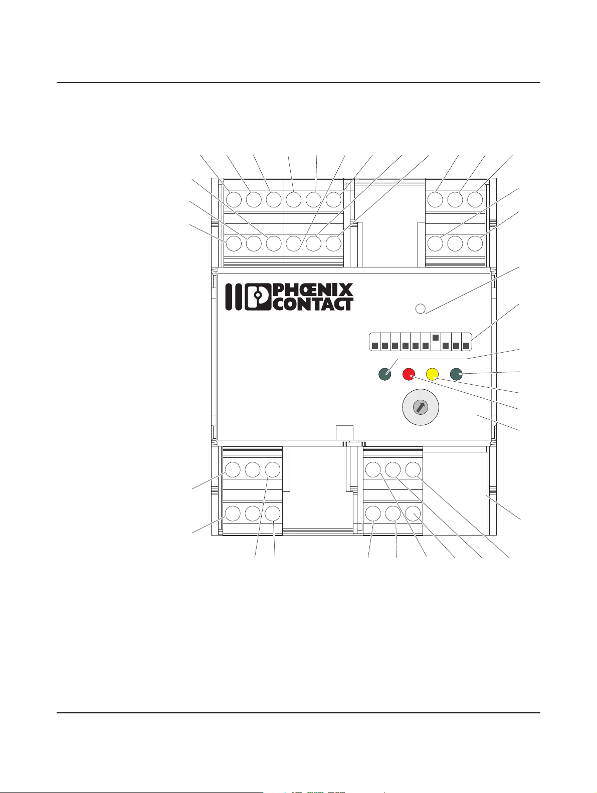
Indicators, operating elements, and connections
2 Indicators, operating elements, and connections
5
4
6
7
8
910
11 12
13
14
15
3
XRML
GND
GNDLRER
PEBA
16
2
17
1
24VENLD
24Va
CRVR
LN
18
19
RESET
1 234 5 678910
POWER ERROR CONNECT
READY
20
21
20
16
32
EV Charge Control
IEC 61851-1
Mode 3
0
1
9
13
10
2
63
8
7
6
6
Dig
PRESET
3
CHARGE
4
70
5
CURRENT
80
22
23
24
C2
V2
R2 R1
PX
35
34
Figure 2-1 Function elements
104924_en_04 PHOENIX CONTACT 11
C1
V1
R4 R3 CP
31 30 29
28
27
25
263233
Page 12
EV Charge Control
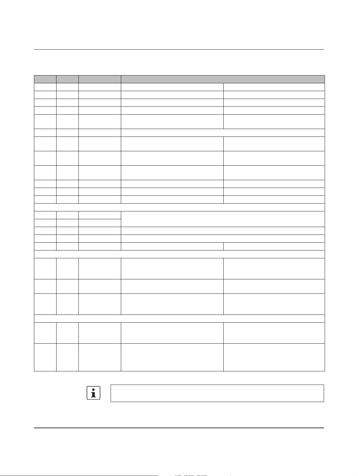
2.1 Connections
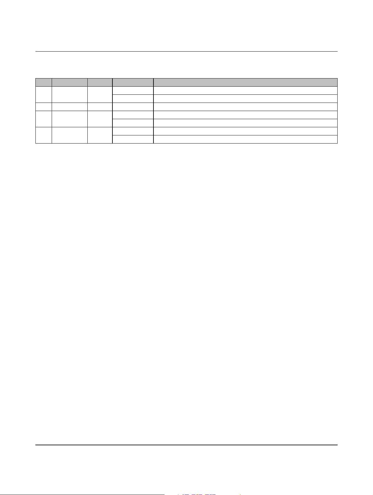
No. Name Meaning Description
1 LD Lock Detection Digital input, locking confirmation Activation via DIP switch 6
2 EN Enable Digital input, enable charging process Activation via DIP switch 7
3 24 V Power Output 24 V DC max. 100 mA
4 ML Manual Lock Digital input, manual locking Activation via DIP switches 4 and 9
5 XR External
Release
6 GND Ground System ground, connected to protective earth ground
7 ER Error Digital output, programmable Default: set when errors occur
8 LR Locking
Request
9 VR Vehicle Ready Digital output, programmable Default: set when the vehicle is ready (sta-
10 GND Ground System ground Connected to protective earth ground
11 CR Charger Ready Digital output, programmable Default: set when PWM is switched on
12 24 Va Power Supply input of the outputs 7.5 V DC ... 30 V DC
13 A RS-485 Connection of external energy/power meters with Modbus RTU protocol
14 B RS-485
15 PE Protective Earth Protective earth ground
16 N Neutral Neutral conductor, power grid
17 L Line Phase, power grid 110 V AC ... 240 V AC (L-N)
Digital input, system status F/charging sta-
Activation via DIP switch 8
tion availability
Error or status E or status F
Digital output, programmable Default: set as long as locking is to remain
active
tus C or D)
26 PX Proximity Test signal Current carrying capacity of the con-
nected plug and cable according to IEC
61851-1
27, 30,
29, 31
R1-R3,
R2-R4
Retaining Relay output for locking Configuration via DIP switches 4 and 5
28 CP Control Pilot Interface signal Communication between the charging
station and vehicle according to
IEC 61851-1
32, 33 V1-V2 Ventilation
1
Relay output for ventilator Can switch on a ventilator when status D
is reached and the enabled inputs and
registers are active.
34, 35 C1-C2 Contactor Relay output for contactor Switches the mains voltage to the vehicle
via an external contactor when status C or
D is reached and the enabled inputs and
registers are active.
1
The ventilation is not monitored.
For additional information, please refer to “Sequence diagrams for charging process” on
page 47.
PHOENIX CONTACT 104924_en_04
12
Page 13
Indicators, operating elements, and connections
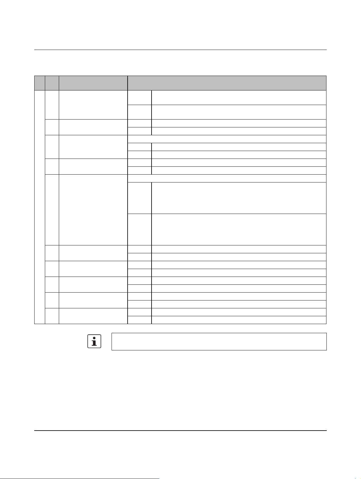
2.2 Diagnostics and status indicators
No. Name Color Status Description
20 POWER Green On Supply voltage present
Flashing (2 Hz) System running
21 ERROR Red On Error (status E or F)
22 CONNECT Yellow On Plug locked
Flashing (2 Hz) Plug inserted
23 READY Green On Vehicle is charging (contactor control between mains and vehicle)
Flashing (2 Hz) Vehicle ready (status C or D)
104924_en_04 PHOENIX CONTACT 13
Page 14
EV Charge Control
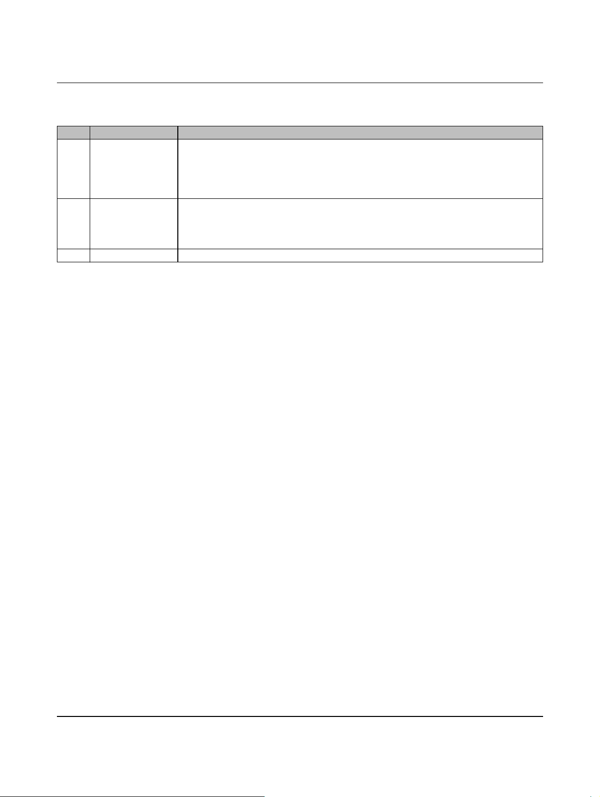
2.3 DIP switches 1 - 10
No.DIP Name Description
19 1 PX request ON PX request, case B,
charging cable with plug on the charger
OFF No PX request, case C,
permanently connected charging cable
2 PX evaluation ON Reject plug/cable with low current carrying capacity
OFF Allow plug/cable with low current carrying capacity
3 PX selection Only relevant when DIP 2 = ON
ON Reject 13 A plug/cable
OFF Reject 13 A and 20 A plug/cable
4 Locking ON Execute locking
OFF Do not execute locking
5 Locking option
(R4 at 0 V, R3 at ≤ 24 V)
6 Locking confirmation ON Evaluate locking confirmation at input LD
7 Enable charging process ON Evaluate enable charging process input EN
8 Charging station availability ON Evaluate charging station availability input XR
9 Manual locking ON Evaluate manual locking input ML
10 Enable via ETH (25) ON Evaluate enable bit in Modbus register
Only relevant when DIP 4 = ON
ON Locking option 1
– DC motor: the locking motor is briefly switched on
– Locking R1 at ≤ 24 V (R2 remains at 0 V)
– Unlocking R2 at ≤ 24 V (R1 remains at 0 V)
OFF Locking option 0
– Lifting solenoid
– R1-R3 is controlled (R1 at ≤ 24 V) for as long as locking is required
– R2-R4 remains in the initial status (R2 at 0 V) the entire time
OFF Do not evaluate locking confirmation at input LD
OFF Do not evaluate enable charging process input EN
OFF Do not evaluate charging station availability input XR
OFF Do not evaluate manual locking input ML
OFF Do not evaluate enable bit in Modbus register
For additional information on configuration, please refer to “Sequence diagrams for
charging process” on page 47.
PHOENIX CONTACT 104924_en_04
14
Page 15
Indicators, operating elements, and connections
2.4 Interfaces/switches
No. Name Description
18 RESET – Pressing the reset button once restarts the system, sets all outputs to the initial status,
and restarts evaluation of the inputs.
– Pressing and holding down the reset button for more than 10 seconds resets all system
variables that were changed via the web interface or the Modbus interface, including the
communication settings for the connection via the Ethernet interface.
24 PRESET CHARGE
CURRENT
25 ETH Communication interface (Ethernet/web interface/Modbus TCP)
– Rotary switch for setting a default/maximum value for the PWM signal on CP during start
and when no external communication is intended.
– Defined values: Dig, 6 A, 10 A, 13 A, 16 A, 20 A, 32 A, 63 A, 70 A, 80 A
Dig = only digital communication
104924_en_04 PHOENIX CONTACT 15
Page 16
EV Charge Control
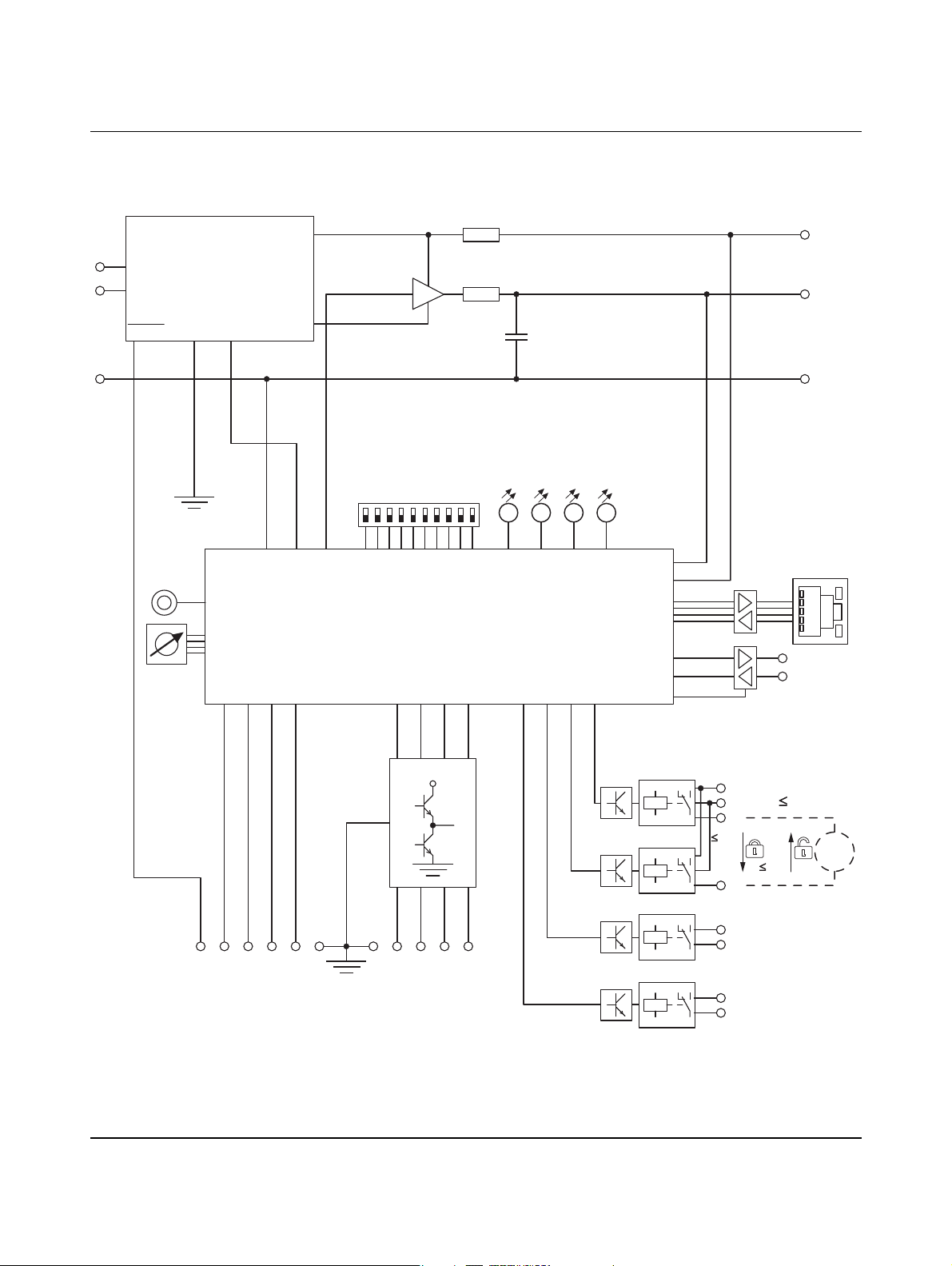
2.5 Block diagram
L
N
PE
Power Supply
230 V AC
+24 V
0,1 A
BCD
Switch
GND
3,6 V
GNDVcPWM
Reset
Preset Charge Current
ML XRLDEN
+12 V
-12 V
DIP Switch
12345678910
Config
LEDs
PWR ERR CON RDY
µC
ER LRVRCR S1 S2S3S4
Proximity Plug
Control Pilot
Protective Earth
Ucp
Upp
MII
PX
CP
PE
ETH
A
B
24 V
24 Va
GND 24 Va
ML XR LD EN
Inputs Outputs
ER LR VR CR
R3
R2
R1
24 V
0 V
R2
V1
V2
C1
C2
Ventilation
Figure 2-2 Schematic diagram
PHOENIX CONTACT 104924_en_04
16
Retaining
0 V
24 V
0 V
24 V
Contactor
M
Page 17

3 Startup
Startup
3.1 Safety notes
Installation only by specialist personnel
Installation, operation, and maintenance may only be carried out by qualified electricians.
Follow the installation instructions as described. When installing and operating the charging
station for electric vehicles, the applicable regulations and safety directives (including national safety directives), as well as general technical regulations, must be observed. The
safety data is provided in the package slip and on the certificates (conformity assessment,
additional approvals where applicable).
Electrostatic discharge
The device contains components that can be damaged or destroyed by electrostatic discharge. When handling the device, observe the necessary safety precautions against electrostatic discharge (ESD) according to EN 61340-5-1 and IEC 61340-5-1.
Do not open or modify the device
With the exception of configuration, opening or modifying the device is not permitted. Do not
repair the device yourself; replace it with an equivalent device. Repairs may only be carried
out by the manufacturer.
Operation in a clean and dry environment only
The IP20 protection (IEC 60529/EN 60529) of the device is intended for use in a clean and
dry environment. Do not subject the device to mechanical and/or thermal loads that exceed
the specified limits.
Disposal
Do not dispose of the device with household waste, it should instead be disposed of in accordance with the currently applicable national regulations. It can also be returned to Phoenix Contact.
104924_en_04 PHOENIX CONTACT 17
Page 18
EV Charge Control
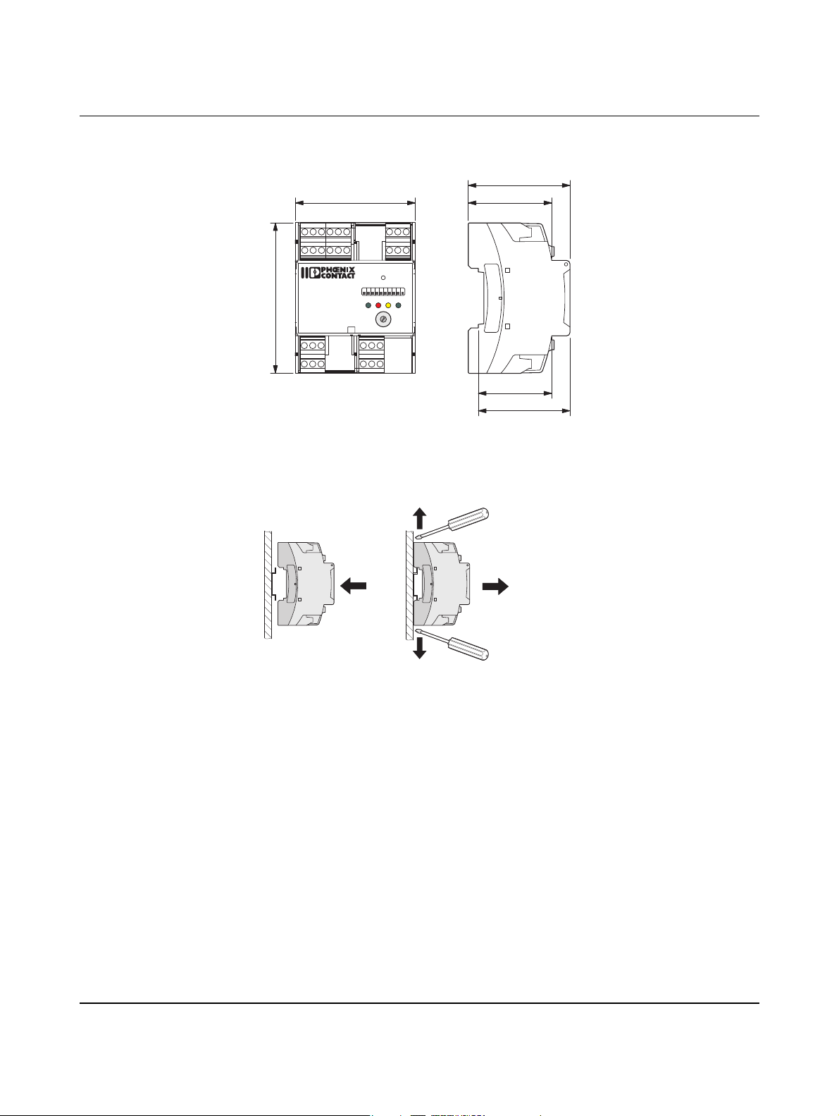
3.2 Dimensions
71,6
XRML
GND
GNDLRER
24Va
CRVR
24V
ENLD
RESET
1234 5678910
READY
90
EV Charge Control
IEC 61851-1
Mode 3
V2
C2
V1
C1
POWER ERROR CONNECT
161332
10
R2 R1 PX
R4 R3 CP
20
0
1
9
2
63
PRESET
8
3
CHARGE
7
4
6
5
CURRENT
80706
Dig
Figure 3-1 Dimensions
PEBA
LN
50
3.3 Mounting on a DIN rail
61
44
55
Figure 3-2 Mounting
The device can be mounted in any position.
Mounting
1. Place the device onto the DIN rail from above.
2. Push the device from the front toward the mounting surface until it engages with a click.
Removal
1. Push down the locking latch using a screwdriver, needle-nose pliers or similar.
2. Pull the bottom edge of the device away from the mounting surface.
3. Pull the device diagonally upwards from the DIN rail.
3.4 Connecting the supply voltage
• Supply voltage to the device via terminal blocks 16 (N), 17 (L), and 15 (PE).
PHOENIX CONTACT 104924_en_04
18
Page 19

Startup
3.5 Configuration
PRESET CHARGE CURRENT rotary switch
• Set the value of the default or maximum current so that the connecting cables to the
charging station and the internal wiring are not overloaded.
Please note that the set maximum current value can occur over several hours.
• If the charging current is specified via digital communication (“Dig” setting), make sure
that a current higher than the maximum current permitted by the installation is not transmitted to the vehicle via serial communication.
DIP switches DIP 1 ... 10: for additional information on configuration, please refer to “Connection examples” on page 35 and “Sequence diagrams for charging process” on page 47.
Web interface: for information on configuration and status requests, please refer to “Configuration via web interface” on page 83.
104924_en_04 PHOENIX CONTACT 19
Page 20

EV Charge Control
PHOENIX CONTACT 104924_en_04
20
Page 21
Signal contacts and charging sequence
4 Signal contacts and charging sequence
4.1 Proximity Plug (PX signal)
Proximity
Plug
Rc
PE
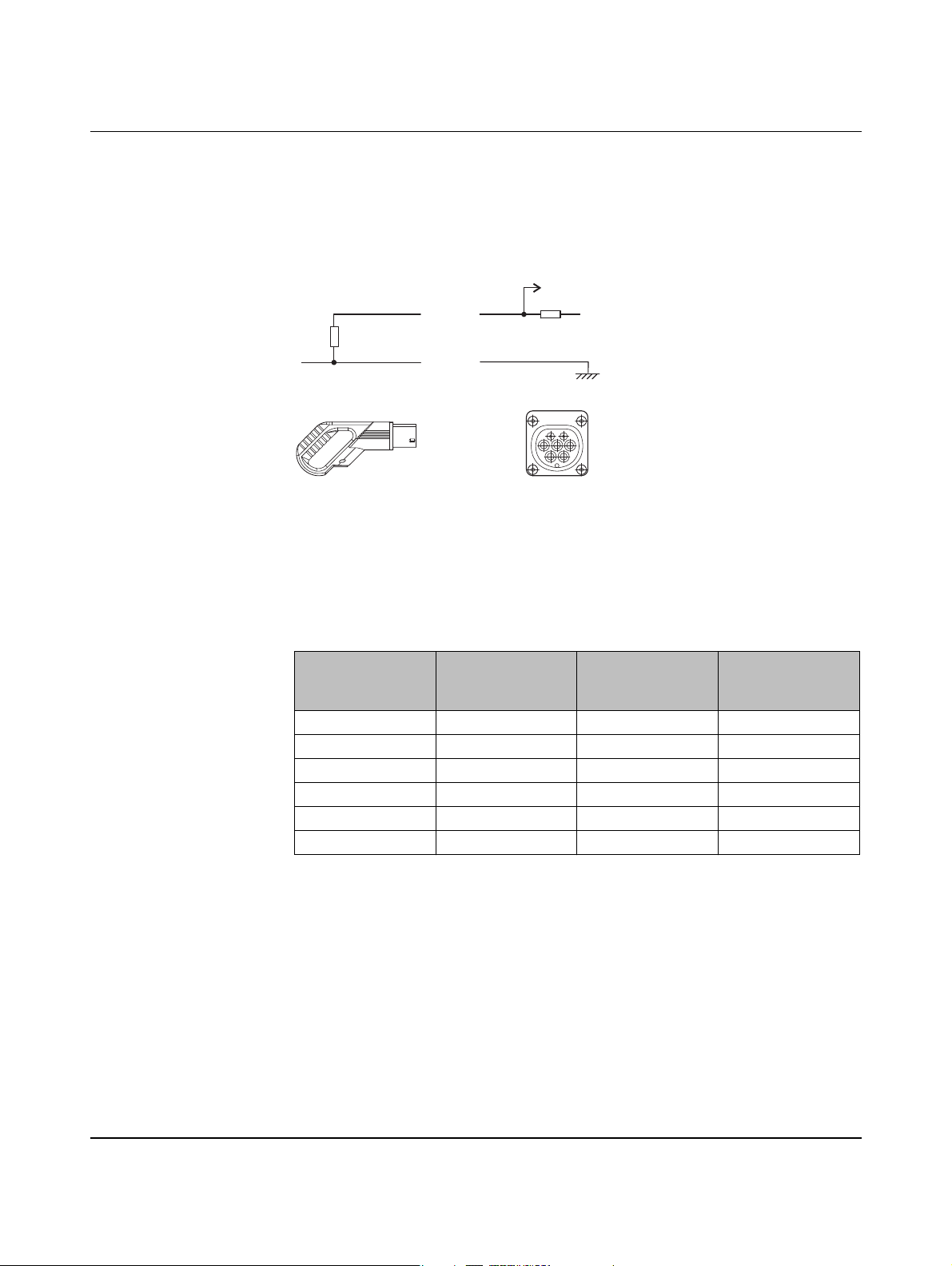
Figure 4-1 Proximity Plug wiring
The current carrying capacity is identified by means of the Rc resistor. The device measures
the resistance value via the PX signal (Proximity Plug) and determines the current carrying
capacity of the connected plug and cable. The coding of the permissible current for the resistance value is defined in IEC 61851-1.
V+
Table 4-1 Coding of the permissible current for the resistance value according to IEC
61851-1
Rc resistance
value according to
the standard
– < 75 Ω Error 0XFFFF
100 Ω 75 Ω ... 150 Ω 63 (70) A 63
220 Ω 150 Ω ... 330 Ω 32 A 32
680 Ω 330 Ω ... 1000 Ω 20 A 20
1500 Ω 1000 Ω ... 2200 Ω 13 A 13
– > 2200 Ω 0 A 0
Measured resistance value
Resulting current
carrying capacity
Register value for
web interface and
Modbus
104924_en_04 PHOENIX CONTACT 21
Page 22
EV Charge Control
4.2 Control Pilot (CP signal)
V
a
V
D1
b
Control Pilot
R1
S1
R3
S2
R2
C
S
GNDXRML
CRVR
24VENLD
EV Charge Control
IEC 61851-1
Mode 3
V2
C2
V1
C1
PWM
GNDLRER
24Va
RESET
1234578
POWER
ERROR
161332
10
R2 R1 PX
R4 R3 CP
Dig
CONNECT
20
12 V
PEBA
LN
9106
READY
63
PRESET
CHARGE
CURRENT
80706
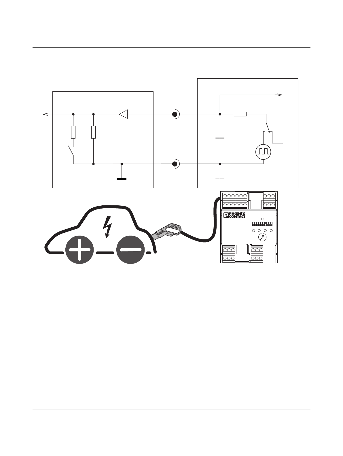
Figure 4-2 Control Pilot wiring
Via the CP signal (Control Pilot), the device specifies the permissible charging current to the
vehicle which is coded as a PWM signal. The vehicle indicates the current vehicle status via
the voltage value Va.
The assignment of the permissible charging current value to the pulse width of the PWM signal and the assignment of the voltage value to the vehicle states is defined in IEC 61851-1
(see table in “Typical charging sequence” on page 25).
PHOENIX CONTACT 104924_en_04
22
Page 23
Signal contacts and charging sequence
4.3 Charging cable connection (case B and C)
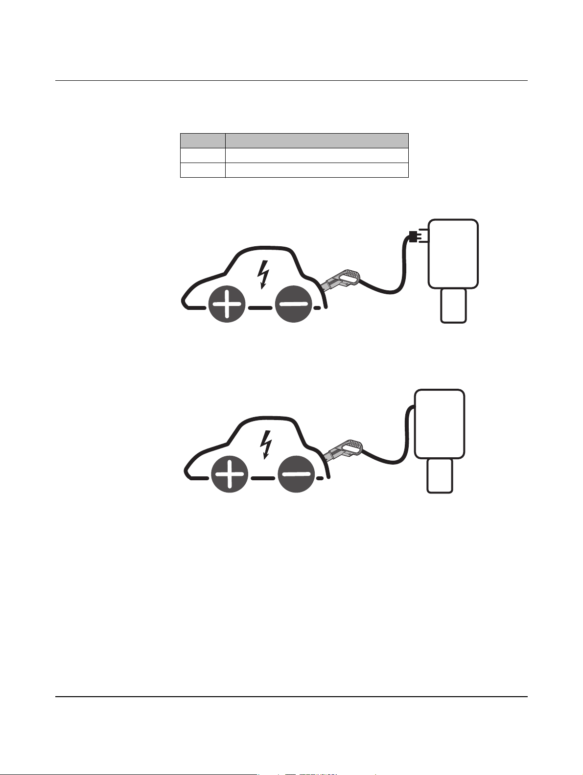
Table 4-2 Case B and C
Case Description
B Plug-in charging cable
C Permanently connected charging cable
Case B
The charging cable is not part of the charging station.
Figure 4-3 Plug-in charging cable - case B
Case C
The charging cable is part of the charging station.
Figure 4-4 Permanently connected charging cable - case C
104924_en_04 PHOENIX CONTACT 23
Page 24
EV Charge Control
4.4 Vehicle status (status A - F)
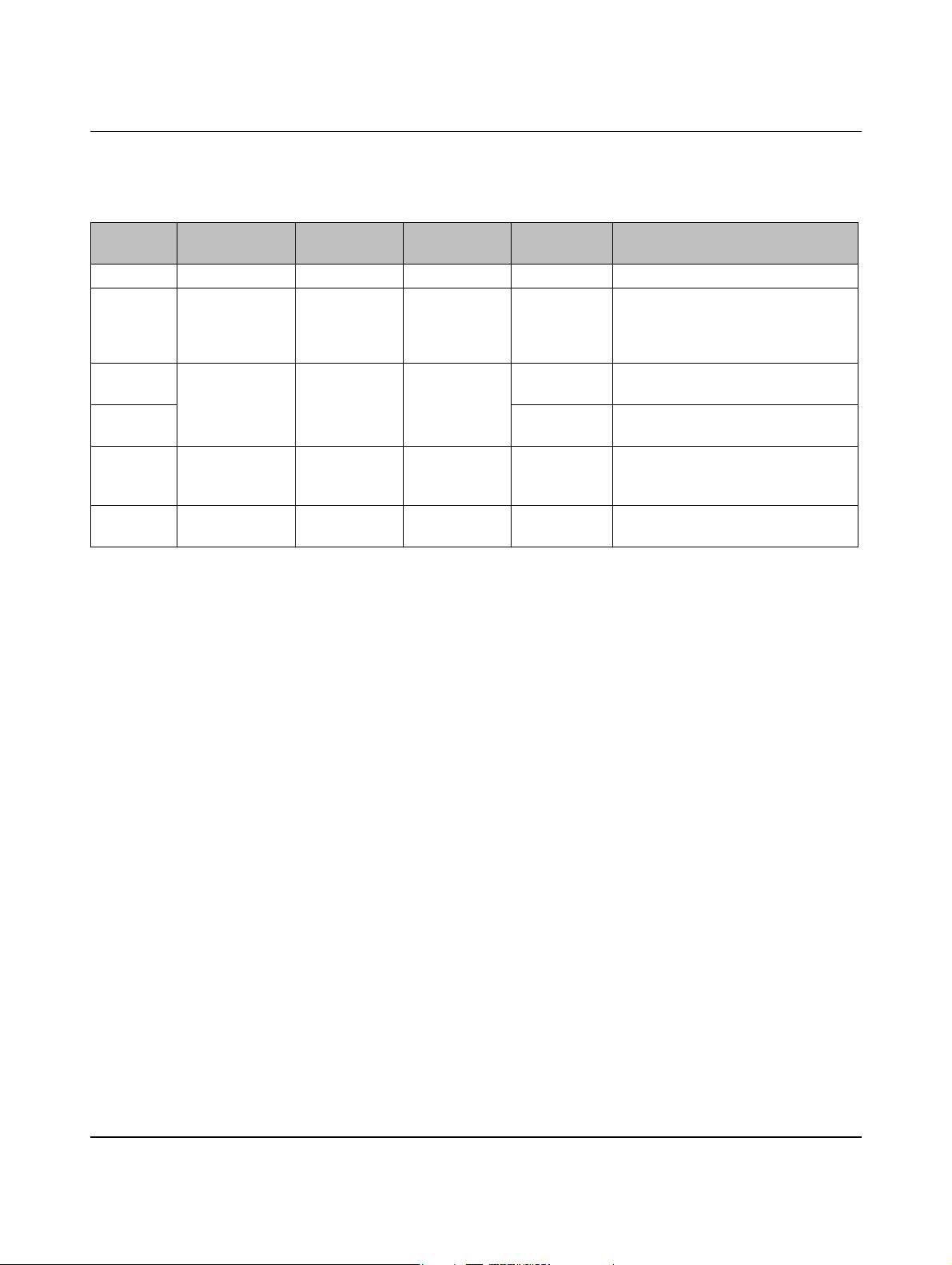
Table 4-3 Vehicle status according to IEC 61851
Vehicle
status
Vehicle connected
S2
1
Charging possible
A No Open No 12 V Vb
B Yes Open No 9 V R2 detected
C Yes Closed Vehicle ready 6 V R3 = 1.3 kΩ ±3%
D 3 V R3 = 270 Ω ±3%
E Yes Open No 0 V Vb = 0: EVSE, short circuit at the
F Yes Open No EVSE not
1
Switch S2 (see Figure 4-2 on page 22)
2
Va = measured voltage in the EV Charge Control
3
Vb = measured voltage in the vehicle
4
EVSE = Electric Vehicle Supply Equipment (charging station)
2
Va
available
Description
3
= 0 V
4
B1 (9 V DC): EVSE
not ready yet
B2 (9 V PWM): EVSE ready
Ventilation not required
Ventilation required
EV Charge Control, power supply not
available
EVSE not available
PHOENIX CONTACT 104924_en_04
24
Page 25
4.5 Typical charging sequence
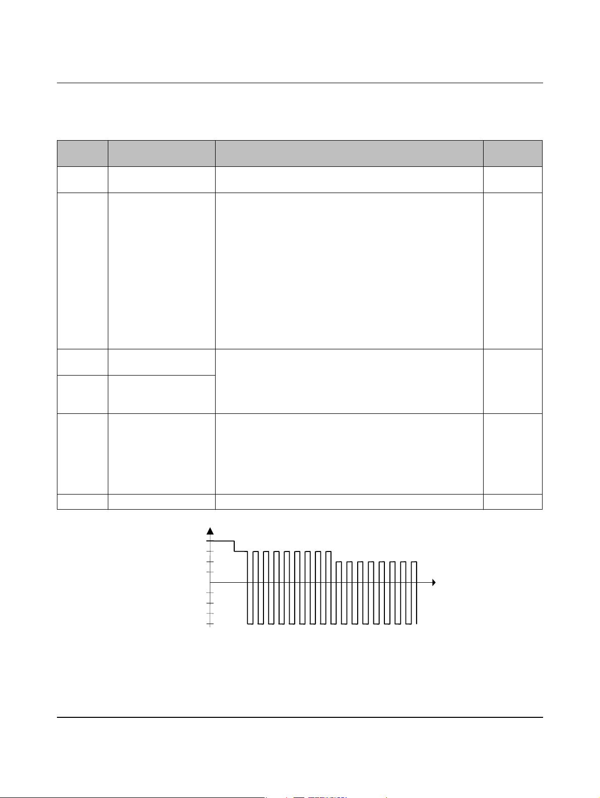
Table 4-4 Charging sequence according to the vehicle status
Signal contacts and charging sequence
Vehicle
State Description CP signal
status
A No charging plug con-
12 V
nected
B Charging plug connected Voltage at the Control Pilot signal (CP) drops to 9 V.
9 V
R2 in vehicle detected.
The voltage value at CP is the result of the series connection of resistor R1 in the charging controller, diode D in the vehicle, and resistor R2 in the vehicle at 12 V.
In status B, the oscillator with pulse width modulation (PWM) is
switched on. The pulse width codes the permissible charging current that the vehicle may take from the charging infrastructure.
The coding is shown in the table below.
B1 (9 V DC): EVSE not ready yet
B2 (9 V PWM): EVSE ready
C Charging without ventila-
tion
D Charging with ventilation
If the vehicle has detected the PWM signal, it connects another resistor R3 parallel to R2 via switch S2. The resulting voltage value is
6 V (ventilation not required) or 3 V (ventilation required).
6 V or 3 V
The charging controller connects the mains voltage to the vehicle
via a contactor and charging cable. The charging process begins.
B Charging completed The vehicle disconnects resistor R3 again via S2.
9 V
The charging controller disconnects the contactor again and with it
the voltage from the charging cable.
Conversely, the charging controller can also indicate to the vehicle
that the charging process should be completed by switching off the
PWM signal.
A Charging plug removed 12 V
CP
12V
-12V
9V
6V
3V
0V
A
B1/B2
C/D
Figure 4-5 Typical signal curve
104924_en_04 PHOENIX CONTACT 25
Page 26
EV Charge Control
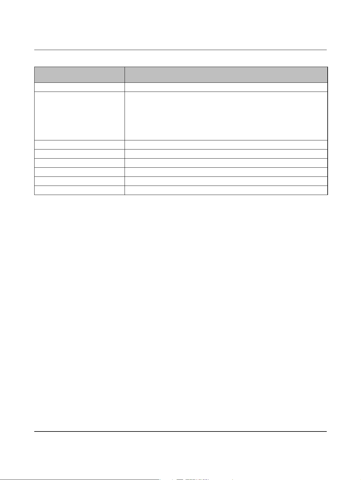
Table 4-5 Controlling the maximum charging current that may be taken
Evaluation of nominal pulse duty
Maximum current that the vehicle may take
factors by the vehicle
Pulse duty factor < 3% Charging is not permitted
3% ≤ pulse duty factor ≤ 7% Indicates that digital communication is being used to control a DC voltage charger
outside the vehicle or to transmit the available current value to a charger inside the
vehicle. Digital communication can also be used with other pulse duty factors.
Charging is only permitted with digital communication.
5% pulse duty factor should be used if the pilot cable is used for digital communica-
tion.
7% < pulse duty factor < 8% Charging is not permitted
8% ≤ pulse duty factor < 10% 6 A
10% ≤ pulse duty factor ≤ 85% Available current = (% of pulse duty factor) x 0.6 A
85% < pulse duty factor ≤ 96% Available current = (% of pulse duty factor - 64) x 2.5 A
96% < pulse duty factor ≤ 97% 80 A
Pulse duty factor > 97% Charging is not permitted
PHOENIX CONTACT 104924_en_04
26
Page 27
4.6 Simplified mode
Signal contacts and charging sequence
V
a
V
D1
b
Control Pilot
R1
S1
R
e
C
S
12 V
PWM
GNDXRML
CRVR
24VENLD
EV Charge Control
IEC 61851-1
Mode 3
V2
C2
V1
C1
GNDLRER
24Va
1234578
POWER
R2 R1 PX
R4 R3 CP
ERROR
10
RESET
161332
Dig
CONNECT
20
PEBA
LN
9106
READY
63
PRESET
CHARGE
CURRENT
80706
Figure 4-6 Simplified Control Pilot wiring
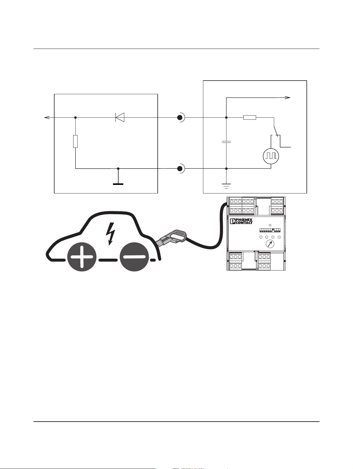
In simplified mode, interim status B is skipped. The permissible charging current value is
limited to 10 A. Resistance value Re corresponds to the parallel connection of resistors R2
and R3 from Figure 4-2. Status C or D can also be reached in simplified mode.
104924_en_04 PHOENIX CONTACT 27
Page 28
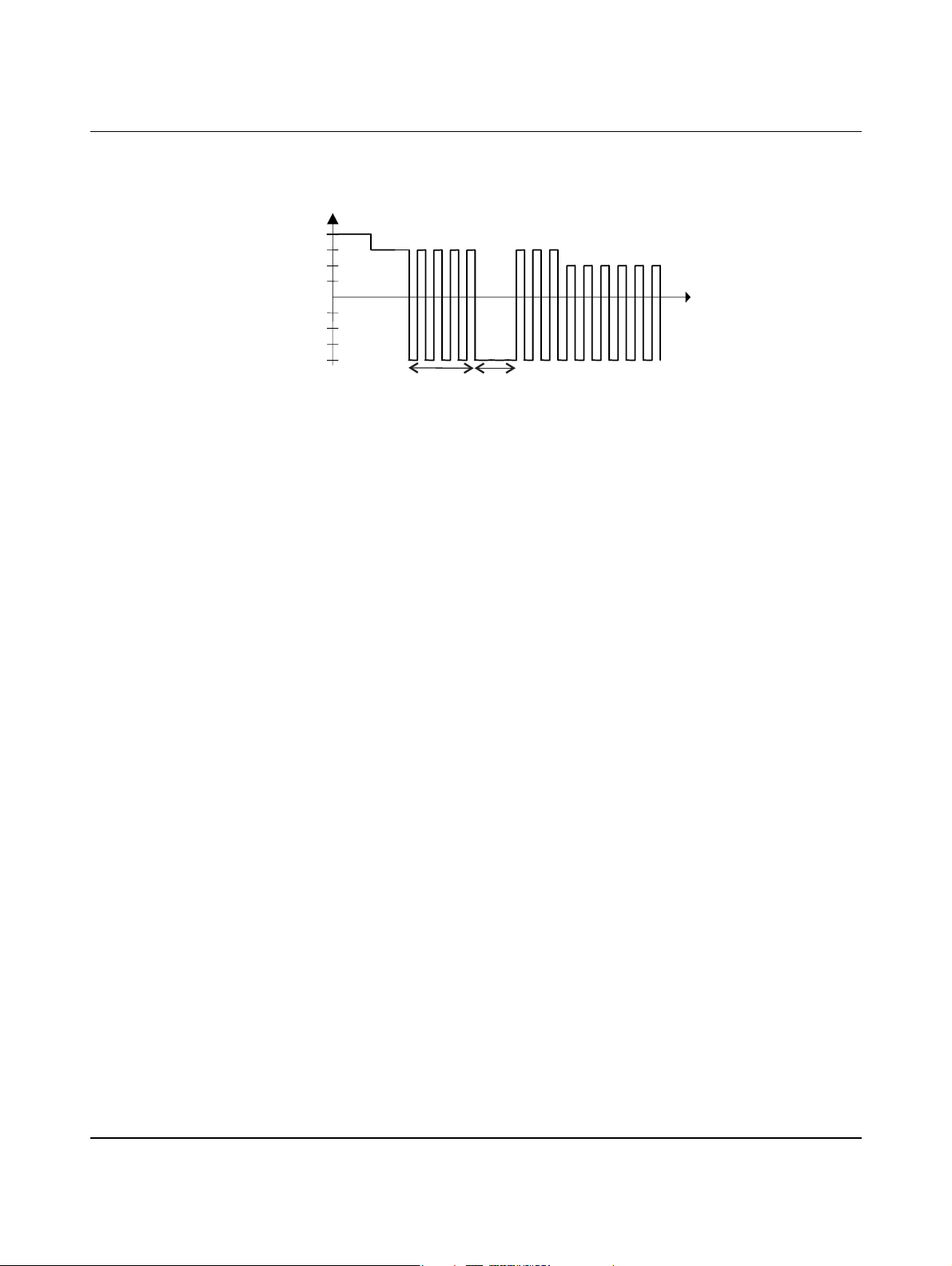
EV Charge Control
4.7 Wake-up sequence
CP
12V
-12V
9V
6V
3V
0V
A
B1
B2
C/D
F
3 s30 s
Figure 4-7 CP signal curve for wake-up sequence
If the connected vehicle switches from status B1 (9 V DC) to B2 (9 V PWM) and the vehicle
does not enter status C or D within 30 seconds, the charging controller simulates the disconnection of the vehicle from the charging station.
The CP signal is set to -12 V DC for 3 seconds. It then switches back to the PWM signal.
This process is only performed once.
PHOENIX CONTACT 104924_en_04
28
Page 29
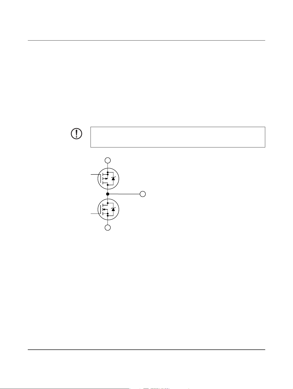
5 Wiring of the inputs and outputs
The circuits with lamps and LEDs are only examples. You can also connect other loads
(e.g., optocouplers, relays or digital inputs of a controller).
5.1 Outputs
In status 0, the outputs are connected to GND and in status 1 they are connected to voltage
input 24Va. A power supply of 7.5 V to 30 V DC can be applied at voltage input 24Va.
The maximum current carrying capacity of each switching transistor is 600 mA. The external
power supply must be adjusted to the connected power.
NOTE: Transistor damage
A supply voltage must never be connected to the outputs, as one of the transistors is controlled at all times and the transistors would be destroyed as a result.
V24a
S
G
Wiring of the inputs and outputs
D
D
G
S
Out
GND
Figure 5-1 Transistor wiring of the outputs
104924_en_04 PHOENIX CONTACT 29
Page 30
EV Charge Control
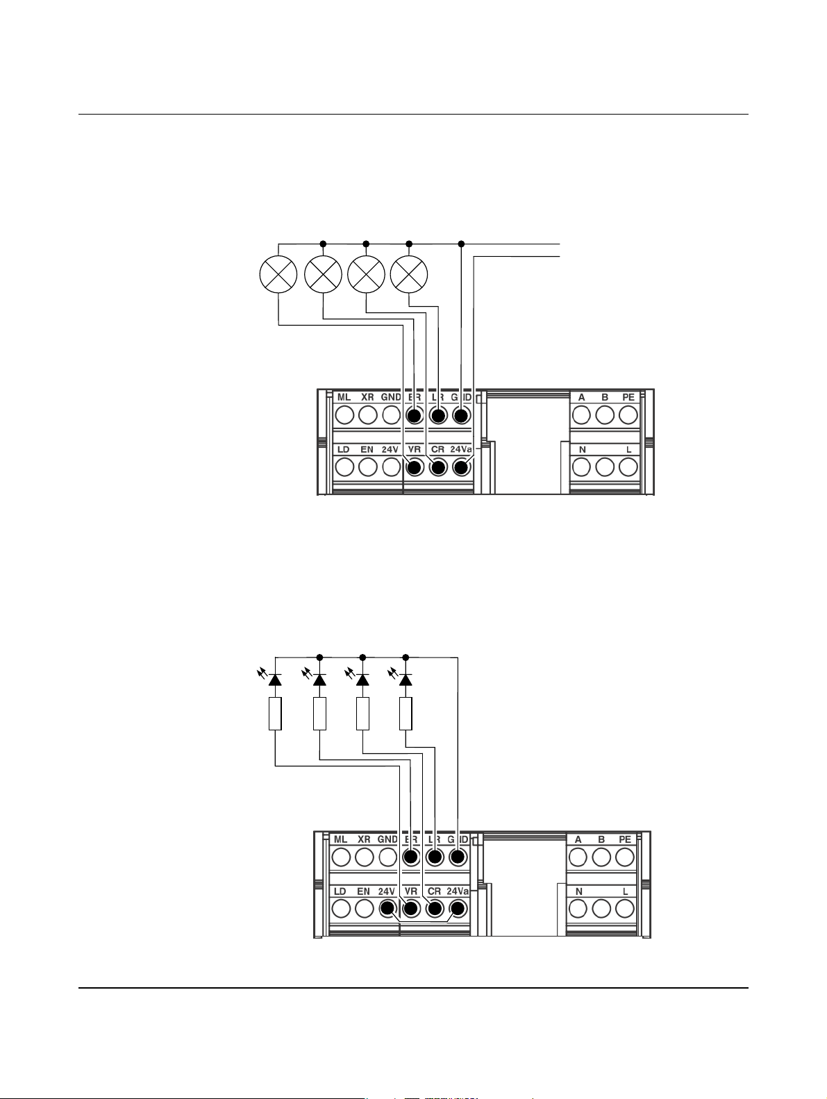
Connection of high-power loads (e.g., lamps)
The output stages are supplied with the required voltage of 7.5 V DC to 30 V DC maximum
via voltage input 24Va. In status 0, the outputs are connected to GND and in status 1 they
are connected to 24Va. GND is connected to PE internally. Please note the maximum current capacity of 600 mA per output.
VR ER CR LR
GND
+7,5 V DC ... +30 V DC
Figure 5-2 Output circuit with lamps
Connection of loads with low current consumption (e.g., LEDs)
The output stages are supplied with the required 24 V DC voltage from voltage output 24V
via voltage input V24a. Voltage output 24V can carry a maximum of 100 mA. In status 0, the
outputs are connected to GND and in status 1 they are connected to 24Va. GND is connected to PE internally.
VR ER CR LR
Figure 5-3 Output circuit with LEDs
PHOENIX CONTACT 104924_en_04
30
Page 31
Wiring of the inputs and outputs
5.2 Inputs
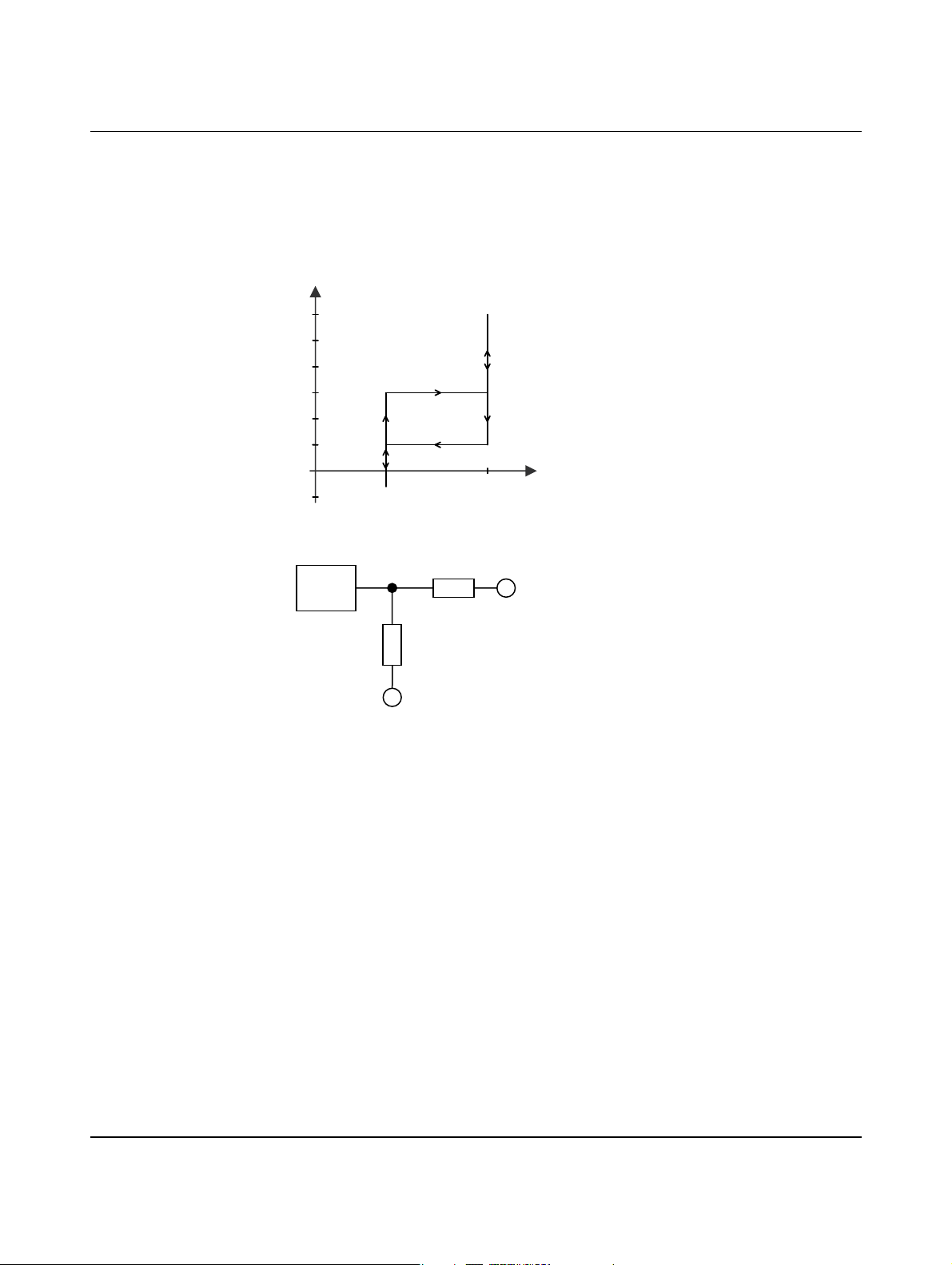
The inputs are designed as voltage dividers for a voltage from -3 V to +30 V.
A current of approximately 8 mA flows across the resistor network at 24 V. Logic 0 is reliably
detected at a voltage of -3 V to +5 V. Logic 1 is reliably detected at a voltage of +15 V to
+30 V.
V
30
25
20
15
10
5
0 1
5
Figure 5-4 Assignment of the logic states to the voltages
μC
In
GND
Figure 5-5 Wiring of the digital inputs
104924_en_04 PHOENIX CONTACT 31
Page 32
EV Charge Control
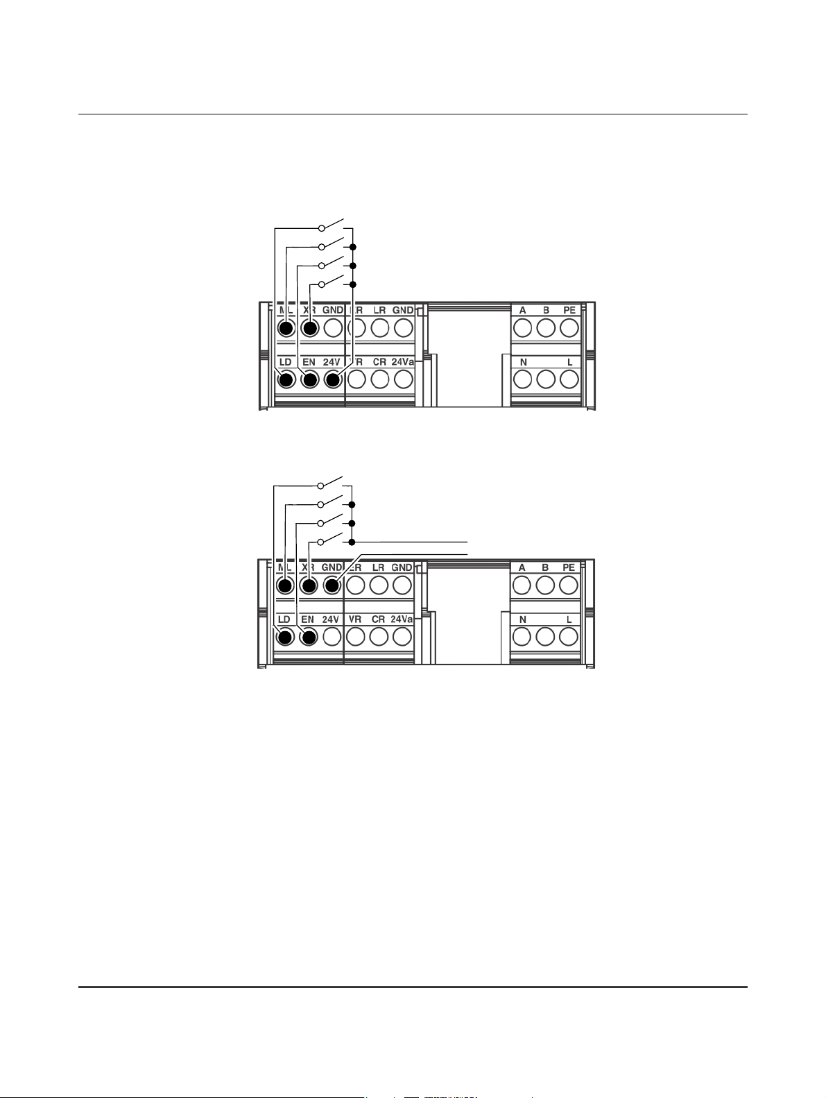
The wiring of the inputs is just an example. The inputs with switches can be supplied by the
internal voltage source as well as by an external 24 V voltage source which uses GND as
the common reference point. The inputs can also be controlled by an external higher-level
controller with 24 V outputs. Here too GND is the common reference point.
Figure 5-6 Inputs at switches with internal supply
24 V DC
GND
Figure 5-7 Inputs at switches with external supply
PHOENIX CONTACT 104924_en_04
32
Page 33
Wiring of the inputs and outputs
5.3 Connecting the energy meter to the RS-485 communication interface
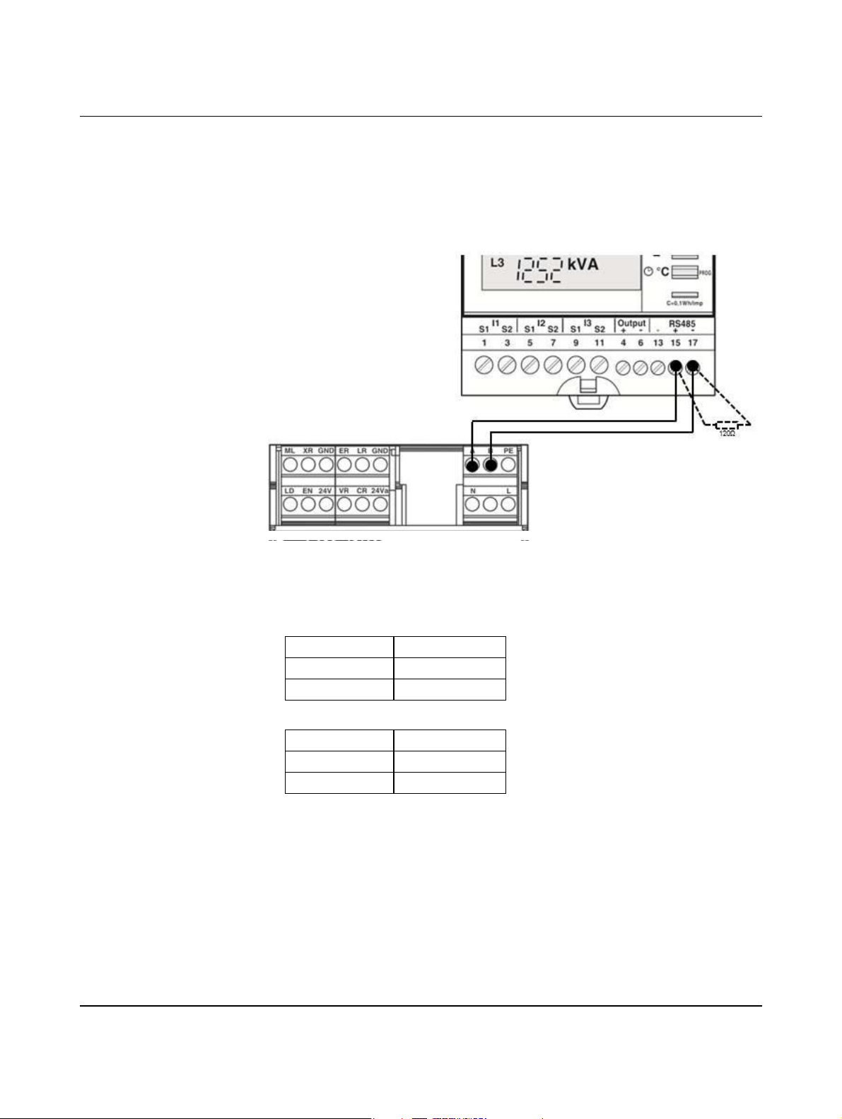
Energy meters which have an RS-485 interface and support the Modbus RTU protocol can
be connected to the serial interface. For some devices it may be necessary to terminate the
cable with a termination resistor.
Figure 5-8 Connecting an energy meter using the EEM-MA250 from Phoenix Contact
as an example
Connecting energy meters from Phoenix Contact
– EEM-MA250 (Order No. 2901363)
EM-CP-PP-ETH EEM-MA 250
A 15 (+)
B 17 (-)
– EEM-350-D-MCB (Order No. 2905849)
EM-CP-PP-ETH EEM-350-D-MCB
A 42 (B+)
B 41 (A-)
The connection is configured via the web interface (see “Energy tab” on page 93) or Modbus TCP (“Modbus description” on page 99).
104924_en_04 PHOENIX CONTACT 33
Page 34

EV Charge Control
PHOENIX CONTACT 104924_en_04
34
Page 35
6 Connection examples
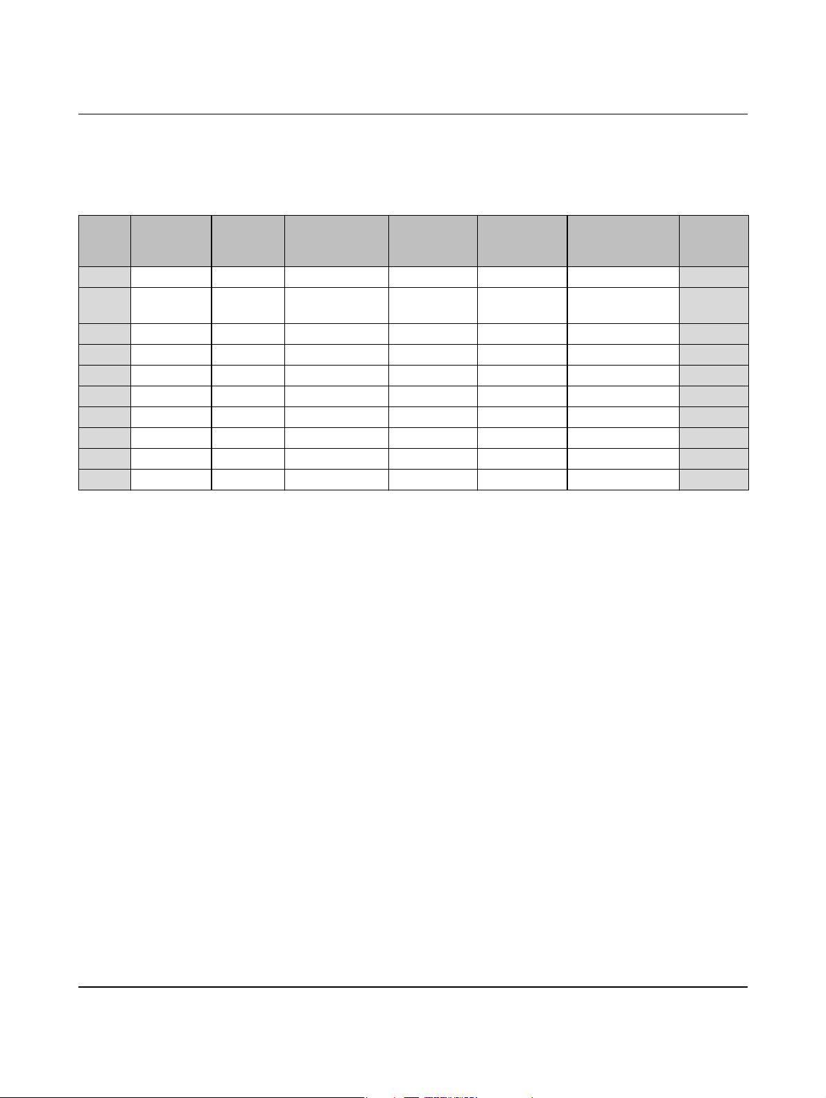
Table 6-1 Overview of the connection examples
Connection examples
Exam-
ple
PX request Current
carrying
capacity
1 None – – – – Input EN page 36
2 None – – – –
3 PX request Test – – – – page 38
4 PX request – Automatic Magnetic – – page 39
5 PX request – Automatic Motor-driven Input LD – page 40
6 PX request – Automatic Motor-driven Input LD Input EN page 41
7 PX request – Manual via ML Motor-driven Input LD Input EN page 42
8 PX request – Automatic Magnetic Input LD – page 43
9 PX request – Automatic Motor-driven Input LD Input EN page 44
10 None – – – – Input EN
1
Additional monitoring of the load contactor via auxiliary contacts
Locking Locking
option
Locking con-
firmation
Enabling of
charging
depends on
Enable bit in regis-
ter address 400
1
See page
page 37
page 45
104924_en_04 PHOENIX CONTACT 35
Page 36
EV Charge Control
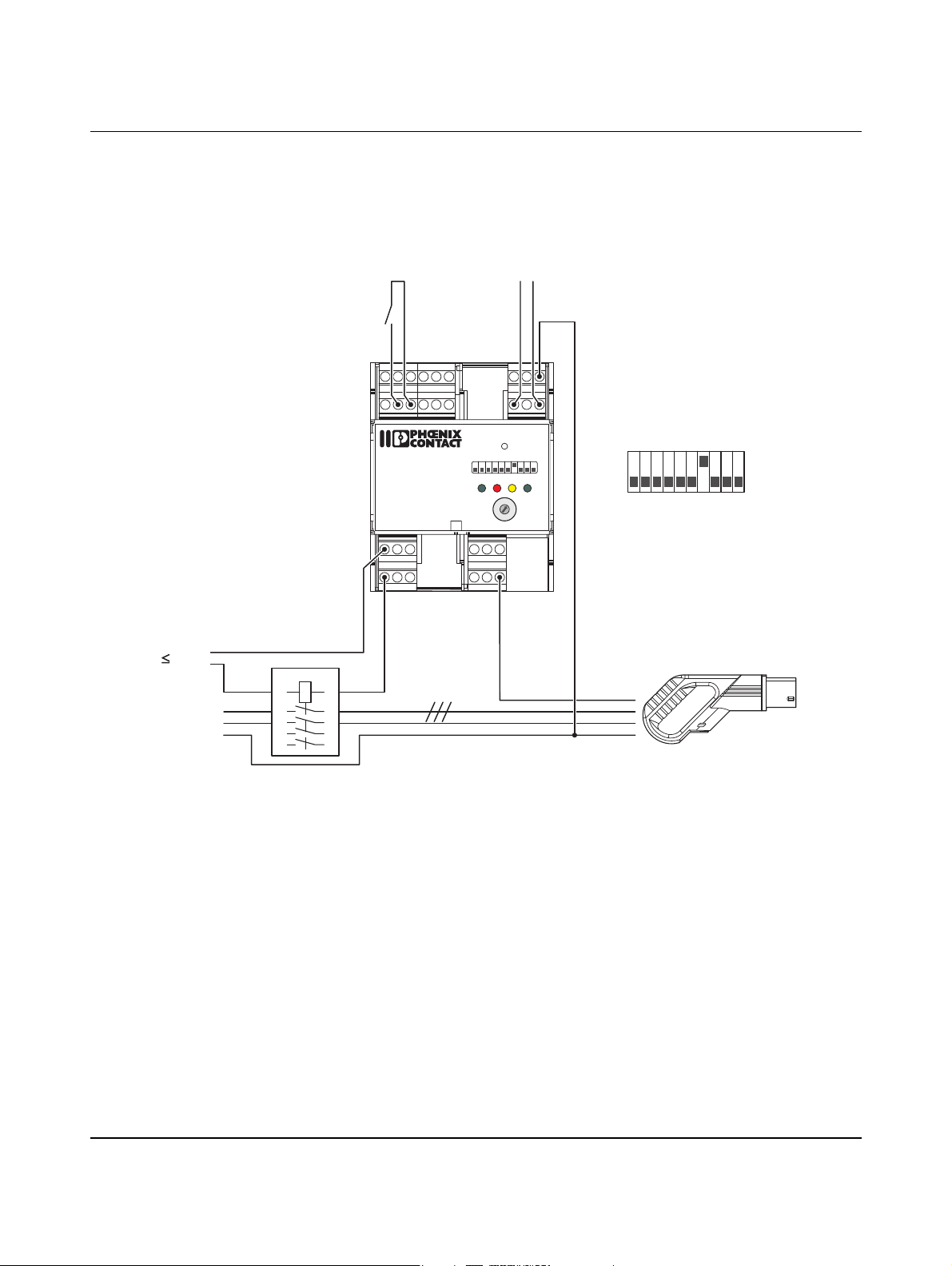
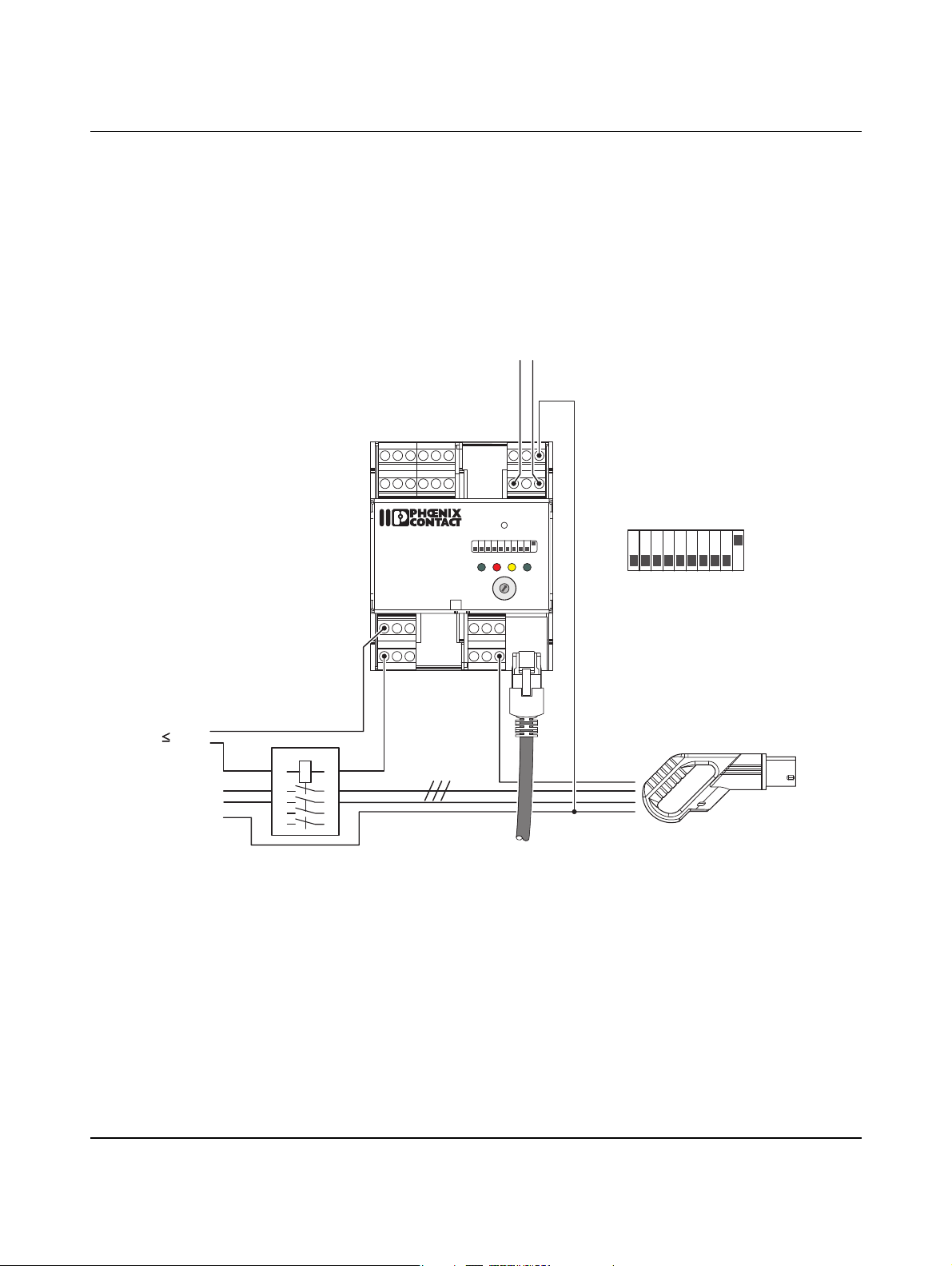
DIP 1 = OFF The charging cable is permanently connected.
DIP 7 = ON Charging is enabled by the switch via digital input EN.
6.1 Charging enabled via input EN
230 V
L, L1-L3
N
PE
1A
1
35
7
N,L
a Load contactor
b Enable charging process
b
c Plug on the charging sta-
tion
XRML
GND
GNDLRER
24Va
CRVR
24VENLD
12 345678910
POWER ERROR CONNECT
EV Charge Control
IEC 61851-1
Mode 3
V2
C2
V1
C1
R2 R1
R4 R3 CP
2A
24
6
8
a
10
RESET
20
161332
9
8
7
6
Dig
PX
PEBA
LN
ON
READY
0
1
2
63
PRESET
3
CHARGE
4
5
CURRENT
80706
1
OFF
10
c
Figure 6-1 Connection example 1
PHOENIX CONTACT 104924_en_04
36
Page 37
Connection examples
6.2 Charging enabled via Ethernet
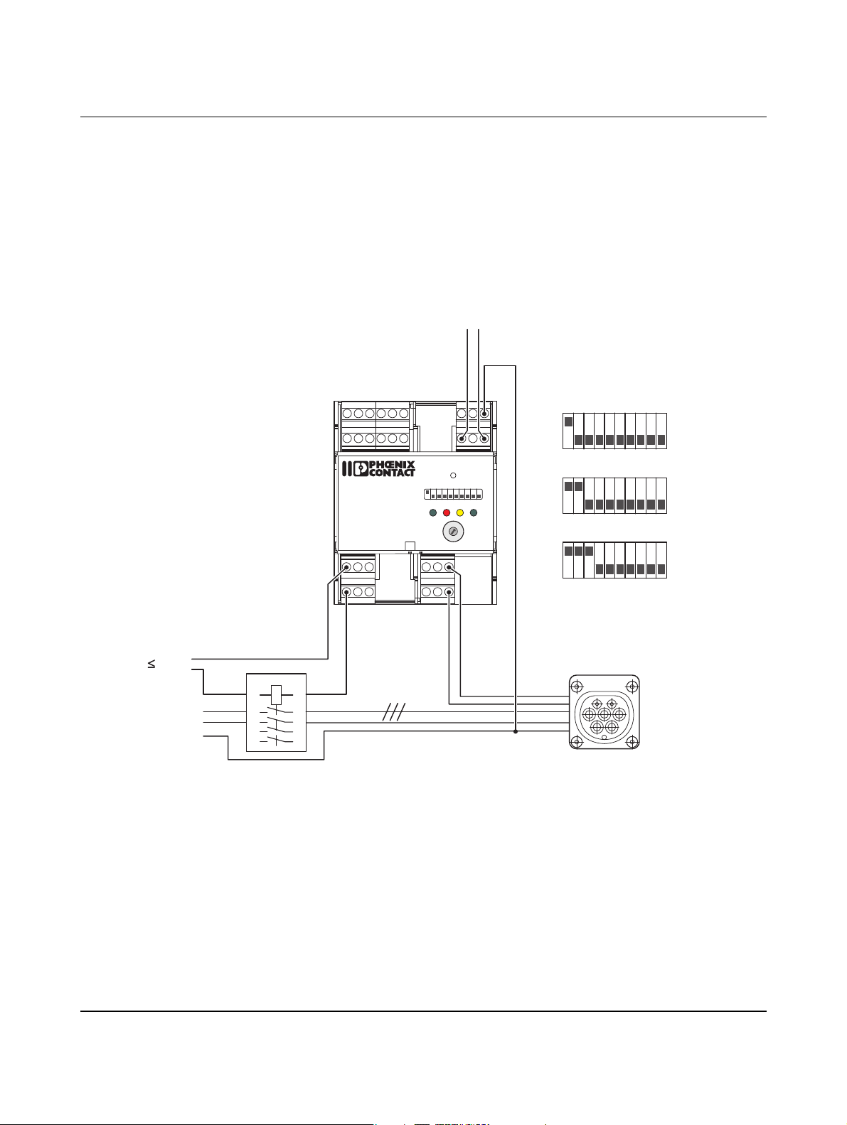
DIP 1 = OFF The charging cable is permanently connected.
DIP 10 = ON Charging is enabled by write access at address 400 via the communication interface or
the web interface.
The charging process starts automatically:
– When there is a 1 in register address 400
– The vehicle is properly connected
– Status C or D has been detected
230 V
L, L1-L3
PE
N,L
a Load contactor
c Plug on the charging sta-
tion
XRML
GND
GNDLRER
24Va
CRVR
24V
ENLD
12 345678910
POWER ERROR CONNECT
EV Charge Control
IEC 61851-1
Mode 3
V2
C2
V1
C1
1A
1
N
35
7
2A
24
6
8
10
R2 R1
R4 R3 CP
RESET
20
161332
0
9
8
7
6
Dig
PX
PEBA
LN
ON
READY
1
2
63
PRESET
3
CHARGE
4
5
CURRENT
80706
1
OFF
10
c
a
Figure 6-2 Connection example 2
104924_en_04 PHOENIX CONTACT 37
Page 38
EV Charge Control
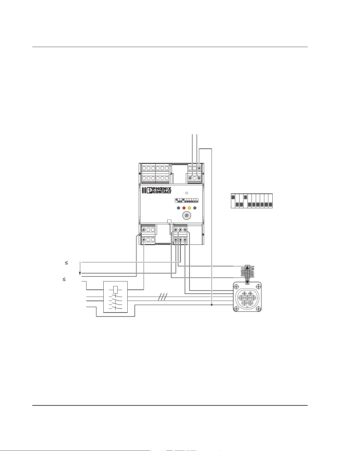
DIP 1 = ON The current carrying capacity of the cable and the plugs is determined via input PX.
DIP 2 = ON – Option A: a charging cable with a current carrying capacity of 13 A or 20 A is rejected.
DIP 2 + 3 = ON – Option B: a charging cable with a current carrying capacity of 13 A is rejected.
6.3 Request of current carrying capacity
The charging process starts automatically:
– When the current carrying capacity requirements are met (option A/B)
– The vehicle is properly connected
– Status C or D has been detected
230 V
L, L1-L3
PE
N,L
a Load contactor
d Socket on the charging sta-
tion
XRML
GND
GNDLRER
24Va
CRVR
24VENLD
12 345678910
POWER ERROR CONNECT
EV Charge Control
IEC 61851-1
Mode 3
V2
C2
V1
C1
1A
1
N
35
7
2A
24
6
8
10
R2 R1
R4 R3 CP
a
RESET
20
161332
0
9
8
7
6
Dig
PX
PEBA
LN
ON
OFF
1
10
ON
A
10
10
OFF
OFF
B
READY
1
2
63
PRESET
3
CHARGE
4
5
CURRENT
80706
1
ON
1
d
Figure 6-3 Connection example 3
PHOENIX CONTACT 104924_en_04
38
Page 39
Connection examples
6.4 Automatic locking via lifting solenoid
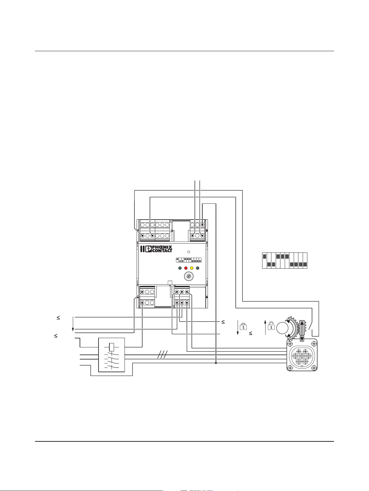
DIP 1 = ON The current carrying capacity of the cable and the plugs is determined via input PX.
DIP 4 = ON Automatic locking
DIP 5 = OFF Locking option 0, actuator = lifting solenoid
DIP 6 = OFF No locking confirmation via digital input LD
The charging process starts automatically:
– When the vehicle is properly connected
– Status C or D has been detected
24 V
0 V
230 V
L, L1-L3
PE
N,L
a Load contactor
e Socket on the charging sta-
tion with lifting solenoid
locking
XRML
GND
GND
LRER
24Va
CRVR
24VENLD
12 345678910
POWER ERROR CONNECT
EV Charge Control
IEC 61851-1
Mode 3
V2
C2
V1
C1
U
in
1A
1
N
35
7
2A
24
6
8
10
R2 R1
R4 R3 CP
RESET
161332
9
8
7
Dig
PX
PEBA
LN
ON
READY
20
0
1
2
63
PRESET
3
CHARGE
4
6
5
CURRENT
80706
1
OFF
10
a
e
Figure 6-4 Connection example 4
104924_en_04 PHOENIX CONTACT 39
Page 40
EV Charge Control
DIP 1 = ON The current carrying capacity of the cable and the plugs is determined via input PX.
DIP 4 = ON Automatic locking
DIP 5 = ON Locking option 1, actuator = DC motor
DIP 6 = ON Locking confirmation via digital input LD
6.5 Automatic locking via DC motor with locking confirmation
The respective switching times of the actuator are set via the web interface
(see “Configuration tab” on page 88).
The charging process starts automatically:
– When locking is indicated at input LD
– The vehicle is properly connected
– Status C or D has been detected
24 V
0 V
230 V
L, L1-L3
PE
N,L
a Load contactor
f Socket on the charging sta-
tion with DC motor locking
and confirmation
XRML
GND
GNDLRER
24Va
CRVR
24VENLD
12 345678910
POWER ERROR CONNECT
EV Charge Control
IEC 61851-1
Mode 3
V2
C2
V1
C1
U
in
1A
1
N
35
7
2A
24
6
8
R2 R1
R4 R3 CP
10
RESET
20
161332
0
9
8
7
6
Dig
PX
PEBA
LN
ON
READY
0 V
24 V
1
M
1
2
63
PRESET
3
CHARGE
4
5
CURRENT
80706
24 V
0 V
OFF
10
a
Figure 6-5 Connection example 5
PHOENIX CONTACT 104924_en_04
40
f
Page 41
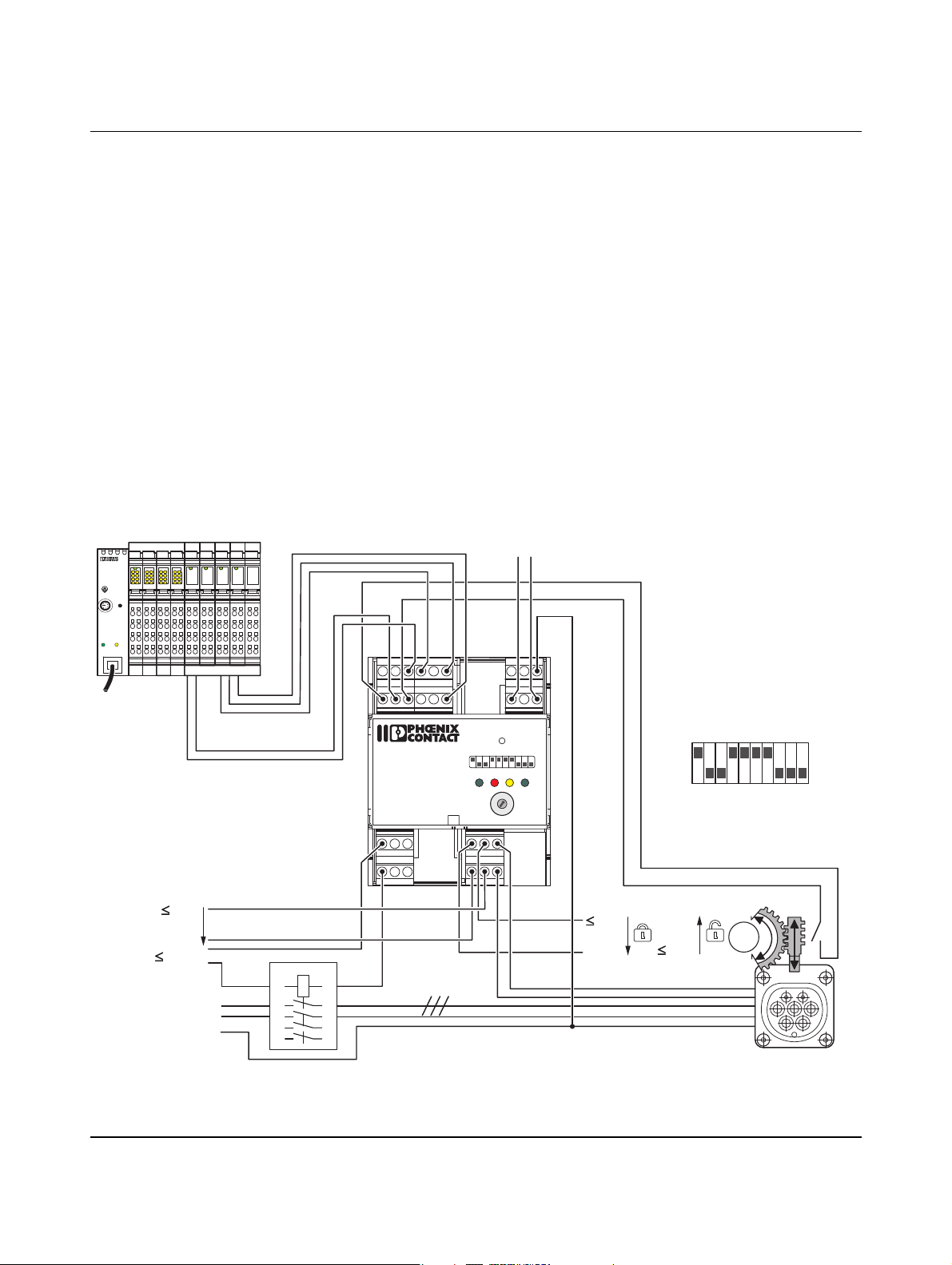
Connection examples
6.6 Automatic locking via DC motor with locking confirmation and charging enabled by external controller
DIP 1 = ON The current carrying capacity of the cable and the plugs is determined via input PX.
DIP 4 = ON Automatic locking
DIP 5 = ON Locking option 1, actuator = DC motor
DIP 6 = ON Locking confirmation via digital input LD
The respective switching times of the actuator are set via the web interface
(see “Configuration tab” on page 88).
DIP 7 = ON Charging is enabled by external controller via digital input EN and error message at exter-
nal controller via digital output ER.
The charging process starts automatically:
– When input EN is at 24 V
– Locking is indicated at input LD
– The vehicle is properly connected
– Status C or D has been detected
ILC 151 ETH
Order-No.: 2700974
HW/FW: 00/100
MAC Addr.: xx.xx.xx.xx
AUTOMATIONWORX
MRESET
STOP
RUN / PROG
PRG
LNK
N,L
DI32
D
12
34
56
87
RESET
1.1 2.1
1.2 2.2
1.3 2.3
ACT
1.4 2.4
US
US
US
12
1
2
12
34
34
34
56
56
56
PD 24V
87
87
87
3.1 4.1
7.1 8.1
5.1 6.1
1.1 2.1
3.2 4.2
7.2 8.2
5.2 6.2
1.2 2.2
3.3 4.3
7.3 8.3
5.3 6.3
1.3 2.3
3.4 4.4
7.4 8.4
5.4 6.4
1.4 2.4
US
PD 24V
PD 24V
PD 24V
PD GND
1.1 2.1
1.1 2.1
1.1 2.1
1.1 2.1
1.2 2.2
1.2 2.2
1.2 2.2
1.2 2.2
1.3 2.3
1.3 2.3
1.3 2.3
1.3 2.3
1.4 2.4
1.4 2.4
1.4 2.4
1.4 2.4
XRML
GND
GNDLRER
24Va
CRVR
24VENLD
EV Charge Control
IEC 61851-1
Mode 3
V2
C2
V1
C1
12 345678910
POWER ERROR CONNECT
10
R2 R1
R4 R3 CP
RESET
20
161332
0
9
8
7
6
Dig
PX
PEBA
LN
READY
1
2
63
PRESET
3
CHARGE
4
5
CURRENT
80706
24 V
U
in
0 V
230 V
L, L1-L3
PE
1A
1
N
35
7
2A
24
6
8
a Load contactor
f Socket on the charging sta-
tion with DC motor locking
and confirmation
ON
1
24 V
0 V
0 V
24 V
M
OFF
10
a
f
Figure 6-6 Connection example 6
104924_en_04 PHOENIX CONTACT 41
Page 42
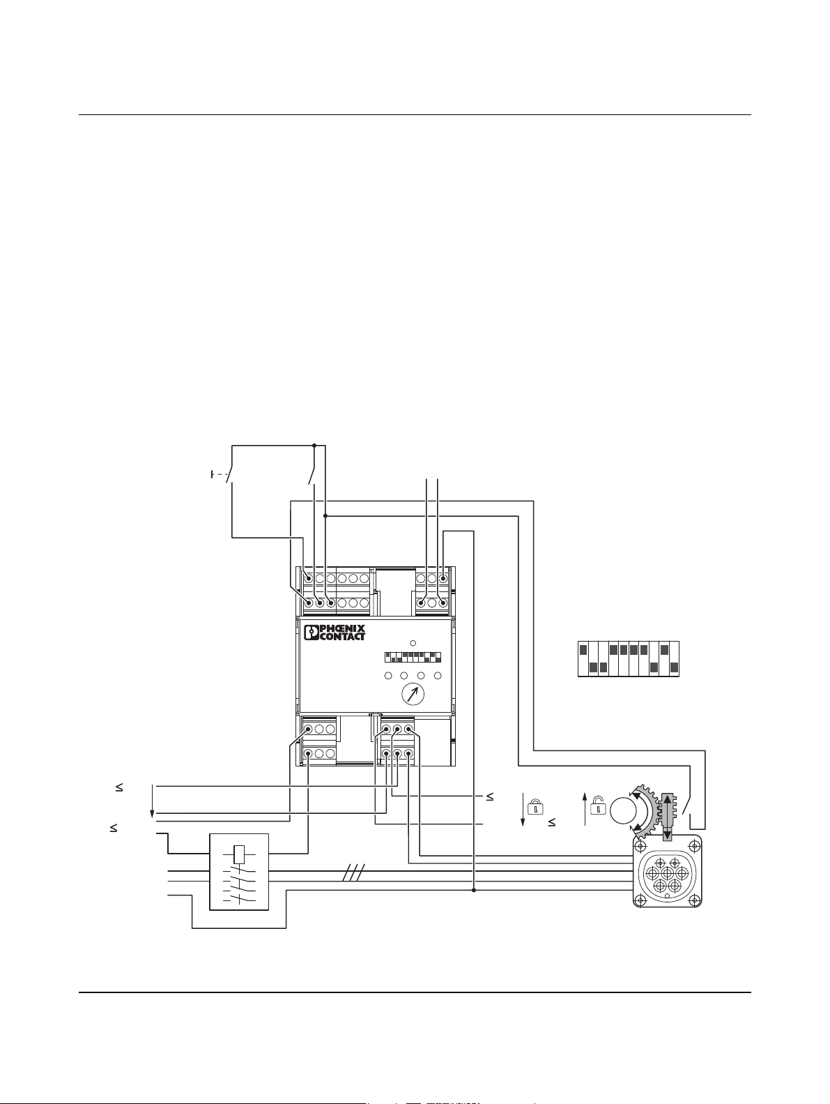
EV Charge Control
DIP 1 = ON The current carrying capacity of the cable and the plugs is determined via input PX.
DIP 4 + 9 = ON Manual locking via button at digital input ML
DIP 5 = ON Locking option 1, actuator = DC motor
DIP 6 = ON Locking confirmation via digital input LD
DIP 7 = ON Charging is enabled by the switch via digital input EN.
6.7 Manual locking via DC motor with locking confirmation and charging enabled via input EN
The respective switching times of the actuator are set via the web interface
(see “Configuration tab” on page 88).
The plug is locked and unlocked by pulses of at least 200 ms at digital input ML.
The charging process starts automatically:
– When input EN is at 24 V
– Locking is indicated at input LD
– The vehicle is properly connected
– Status C or D has been detected
a Load contactor
g
b
N,L
b Enable charging process
f Socket on the charging sta-
tion with electric motor
locking and confirmation
g Button
24 V
0 V
230 V
L, L1-L3
PE
XRML
GND
GNDLRER
24Va
CRVR
24VENLD
1234578
POWER
EV Charge Control
IEC 61851-1
Mode 3
V2
C2
V1
C1
U
in
1A
1
N
35
7
2A
24
6
8
R2 R1 PX
R4 R3 CP
ERROR
10
RESET
20
161332
Dig
CONNECT
80706
63
9106
READY
PRESET
CHARGE
CURRENT
PEBA
LN
ON
OFF
10
24 V
0 V
0 V
24 V
1
M
f
a
Figure 6-7 Connection example 7
PHOENIX CONTACT 104924_en_04
42
Page 43
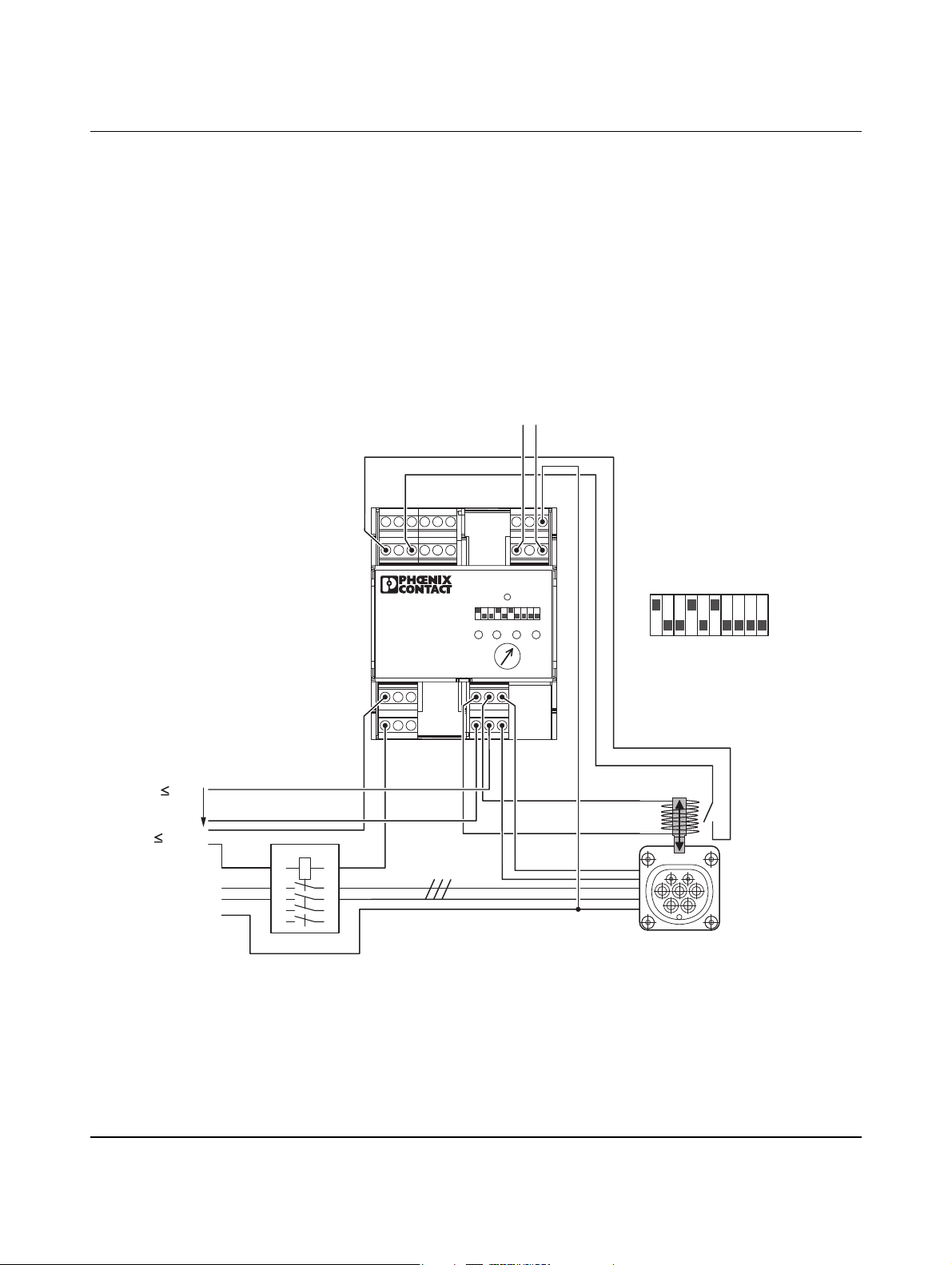
Connection examples
6.8 Automatic locking via lifting solenoid with locking confirmation
DIP 1 = ON The current carrying capacity of the cable and the plugs is determined via input PX.
DIP 4 = ON Automatic locking
DIP 5 = OFF Locking option 0, actuator = lifting solenoid
DIP 6 = ON Locking confirmation via digital input LD
The charging process starts automatically:
– When locking is indicated at input LD
– The vehicle is properly connected
– Status C or D has been detected
24 V
0 V
230 V
L, L1-L3
PE
N,L
a Load contactor
e Socket on the charging
station with lifting solenoid locking
XRML
GND
GNDLRER
24Va
CRVR
24V
ENLD
1234578
POWER
ERROR
EV Charge Control
IEC 61851-1
Mode 3
V2
C2
V1
C1
U
in
1A
1
N
35
7
2A
24
6
8
10
R2 R1 PX
R4 R3 CP
RESET
20
161332
Dig
CONNECT
PEBA
LN
ON
9106
READY
63
PRESET
CHARGE
CURRENT
80706
1
OFF
10
e
a
Figure 6-8 Connection example 8
104924_en_04 PHOENIX CONTACT 43
Page 44
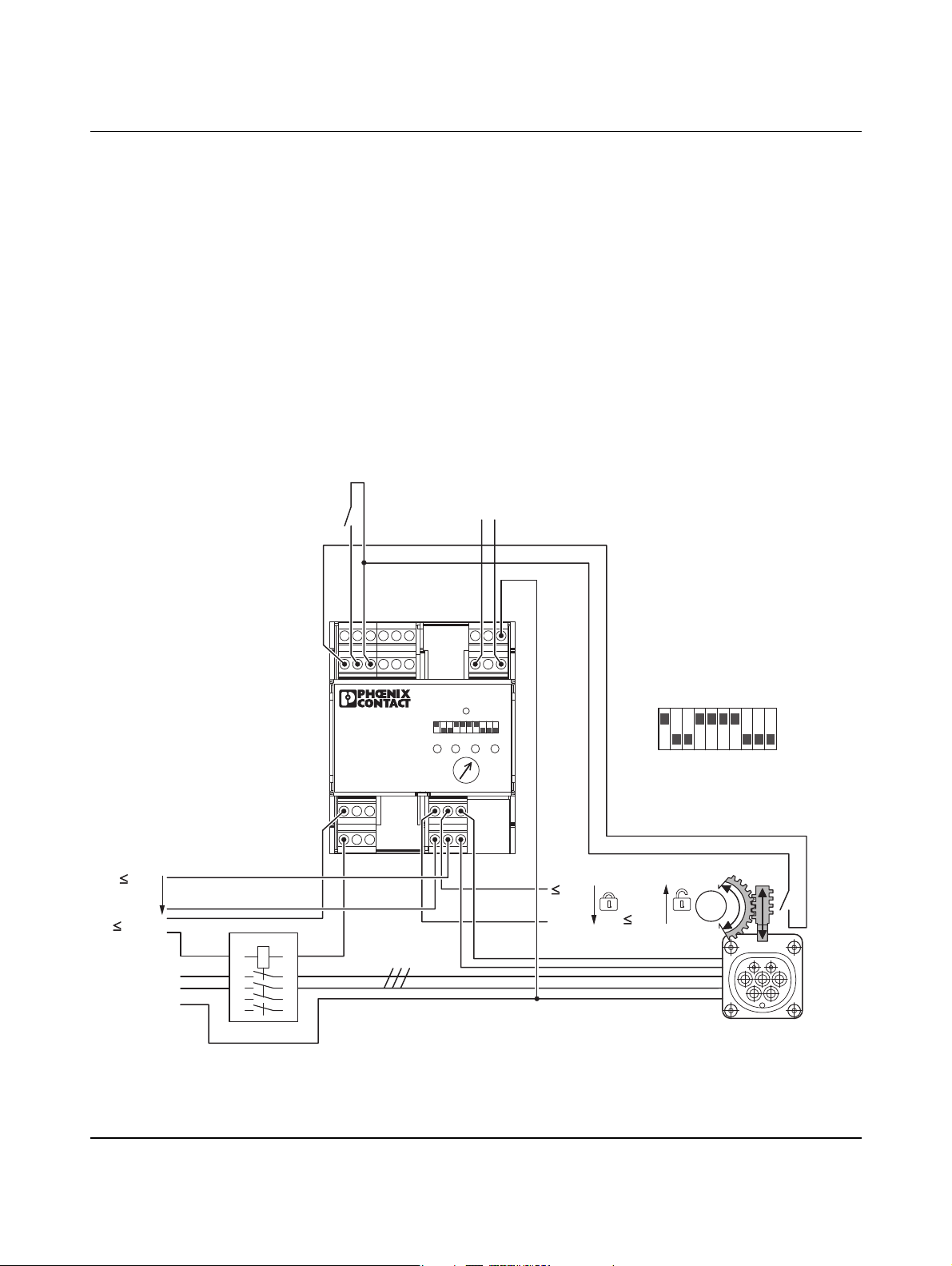
EV Charge Control
DIP 1 = ON The current carrying capacity of the cable and the plugs is determined via input PX.
DIP 4 = ON Automatic locking
DIP 5 = ON Locking option 1, actuator = DC motor
DIP 6 = ON Locking confirmation via digital input LD
DIP 7 = ON Charging is enabled by the switch via digital input EN.
6.9 Automatic locking via DC motor with locking confirmation and charging enabled via input EN
The respective switching times of the actuator are set via the web interface
(see “Configuration tab” on page 88).
The charging process starts automatically:
– When input EN is at 24 V
– Locking is indicated at input LD
– The vehicle is properly connected
– Status C or D has been detected
24 V
0 V
230 V
L, L1-L3
PE
b
N,L
b Enable charging process
f Socket on the charging sta-
tion with electric motor
locking and confirmation
XRML
GND
a Load contactor
GNDLRER
24Va
CRVR
24VENLD
1234578
POWER
EV Charge Control
IEC 61851-1
Mode 3
V2
C2
V1
C1
U
in
1A
1
N
35
7
2A
24
6
8
R2 R1
R4 R3 CP
ERROR
10
RESET
20
161332
Dig
PX
CONNECT
80706
63
9106
READY
PRESET
CHARGE
CURRENT
PEBA
LN
ON
OFF
10
24 V
0 V
0 V
24 V
1
M
a
Figure 6-9 Connection example 9
PHOENIX CONTACT 104924_en_04
44
f
Page 45
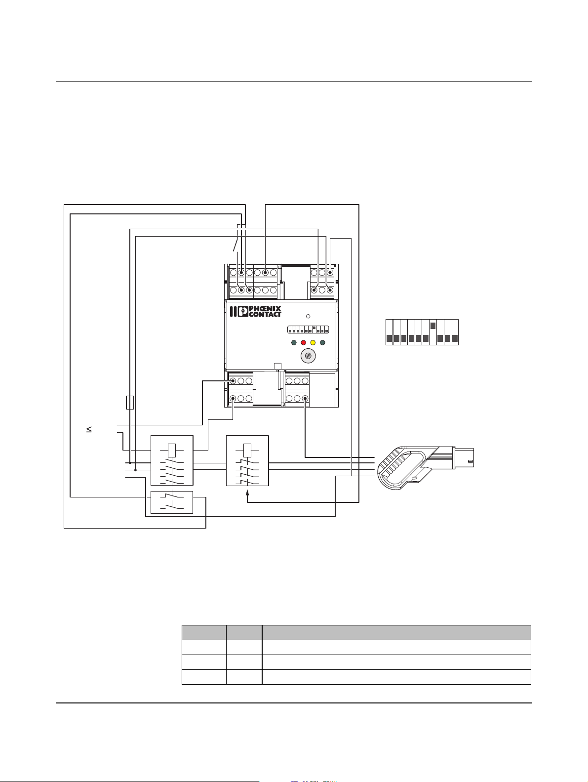
Connection examples
6.10 Monitoring the load contactor via auxiliary contacts
DIP 1 = OFF The charging cable is permanently connected.
DIP 7 = ON Charging is enabled by the switch via digital input EN.
DIP 8 = OFF Modified evaluation of input XR. The evaluation is configured via the web interface or as an
alternative, via Modbus.
a Load contactor with auxiliary
contacts
b
XRML
GND
GNDLRER
24Va
CRVR
24V
ENLD
PEBA
LN
b Enable charging process
c Plug on the charging station
d Redundant switching element
EV Charge Control
IEC 61851-1
Mode 3
V2
C2
V1
C1
RESET
1 234 5678910
POWER ERROR CONNECT
20
161332
0
1
9
2
63
8
3
7
4
6
10
5
80706
Dig
PX
R2 R1
R4 R3 CP
READY
PRESET
CHARGE
CURRENT
ON
1
230 V
L, L1-L3
PE
1A
1
N
35
7 1224
2A
2 4
6
8 11 23
1A
1
35
7
2A
2 4
6
d
8
a
Figure 6-10 Connection example 10
Web interface • Click the “Energy” tab, and then click the “EM Config” button.
• Under “Contactor Monitoring”, select “Aux. Contact NC” (NC = Normally Closed) from
the list.
• On the “Status” tab, for output “LR”, select “Contactor Failure” from the list.
OFF
10
c
Modbus registers
Address Value Explanation
390 3 Evaluation of the N/C auxiliary contact on the load contactor
519 500 Delay for evaluation of the auxiliary contact, 500 ms (default)
328 35 LR is configured for the event “contactor error”
104924_en_04 PHOENIX CONTACT 45
Page 46

EV Charge Control
PHOENIX CONTACT 104924_en_04
46
Page 47
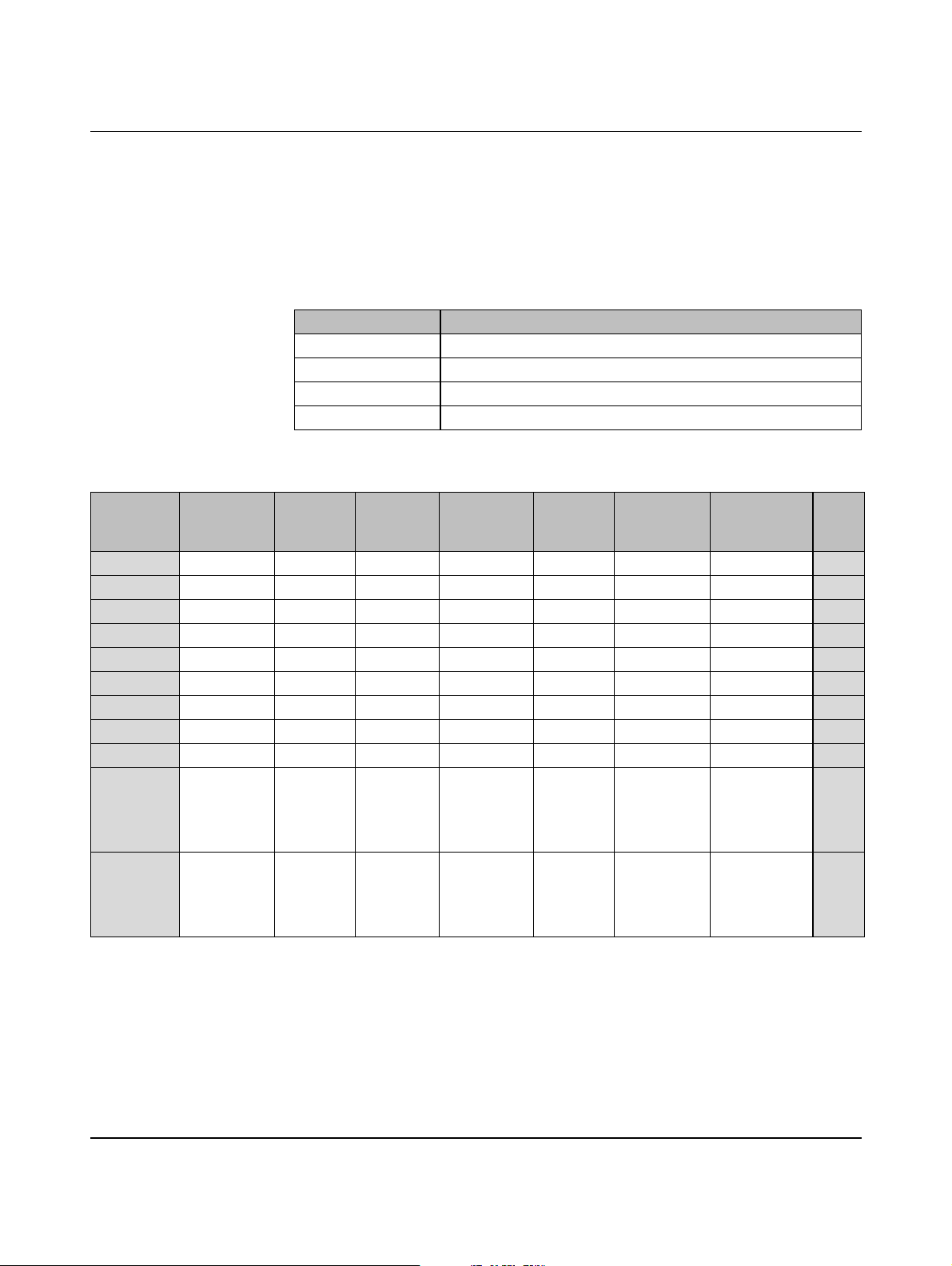
Sequence diagrams for charging process
7 Sequence diagrams for charging process
The examples are based on the default configuration of the digital outputs (““Status” tab” on
page 84).
Default value
Table 7-1 Preset configuration of the digital outputs
Digital output Default value
CR PWM on
LR Locking Request
VR State C or D
ER State E or State F (Error)
Table 7-2 Overview of the charging sequences
Charging
sequence
1 None – – – – – – 48
2 PX request – – – – – – 50
3 PX request Test – – – – – 52
4 None – Manual Magnetic – – – 55
5 None – Automatic Magnetic – – – 59
6 None – Automatic Motor-driven – – – 62
7 None – Automatic Motor-driven Input LD – – 65
8 None – Automatic Magnetic – – Input EN 69
9 None – Automatic Magnetic – Input XR – 72
10 None – Manual Magnetic – –
11 PX request Test Manual Motor-driven Input LD Input XR
PX request Current
carrying
capacity
Locking Locking
option
Locking
confirma-
tion
Charging
station
availability
Enabling of
charging
depends on
Input EN
Enable bit in
register
address 400
Input EN
Enable bit in
register
address 400
See
page
76
79
104924_en_04 PHOENIX CONTACT 47
Page 48
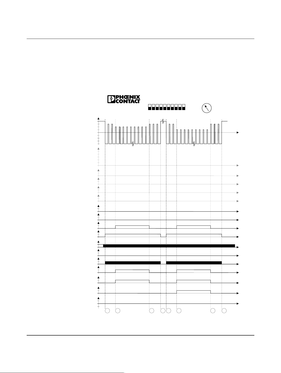
EV Charge Control
DIP 1 = OFF No PX request, permanently connected charging cable (case C with status C and
7.1 Charging sequence 1
D)
If the system is switched on, the PW (POWER) LED is constantly lit.
If the system is being initialized, the PW (POWER) LED flashes at 2 Hz. Vehicle status A is
reached.
All outputs are at 0. No relay is set. Evaluation of the inputs is started immediately.
20
16
32
13
63
10
70
6
80
Dig
S7S
8
CP
12V
-12V
PP[ Ω]
1500
ML
XR
Dig. IN
EN
ER
VR
Dig. OUT
CR
PW
ER
CN
LED
RD
C1/C2
V1/V2
R1-R2
EV Charge Control
IEC 61851-1
Mode 3
9V
6V
3V
0V
∞
680
220
100
0
1
0
1
0
LD
1
0
1
0
1
0
LR
1
0
1
0
1
0
1
0
1
0
1
0
1
0
1
0
1
0
V
in
0
-V
in
S1S
ON
5
1234
2
S3S4S5S
678910
OFF
6
Figure 7-1 Charging sequence 1
PHOENIX CONTACT 104924_en_04
48
Page 49
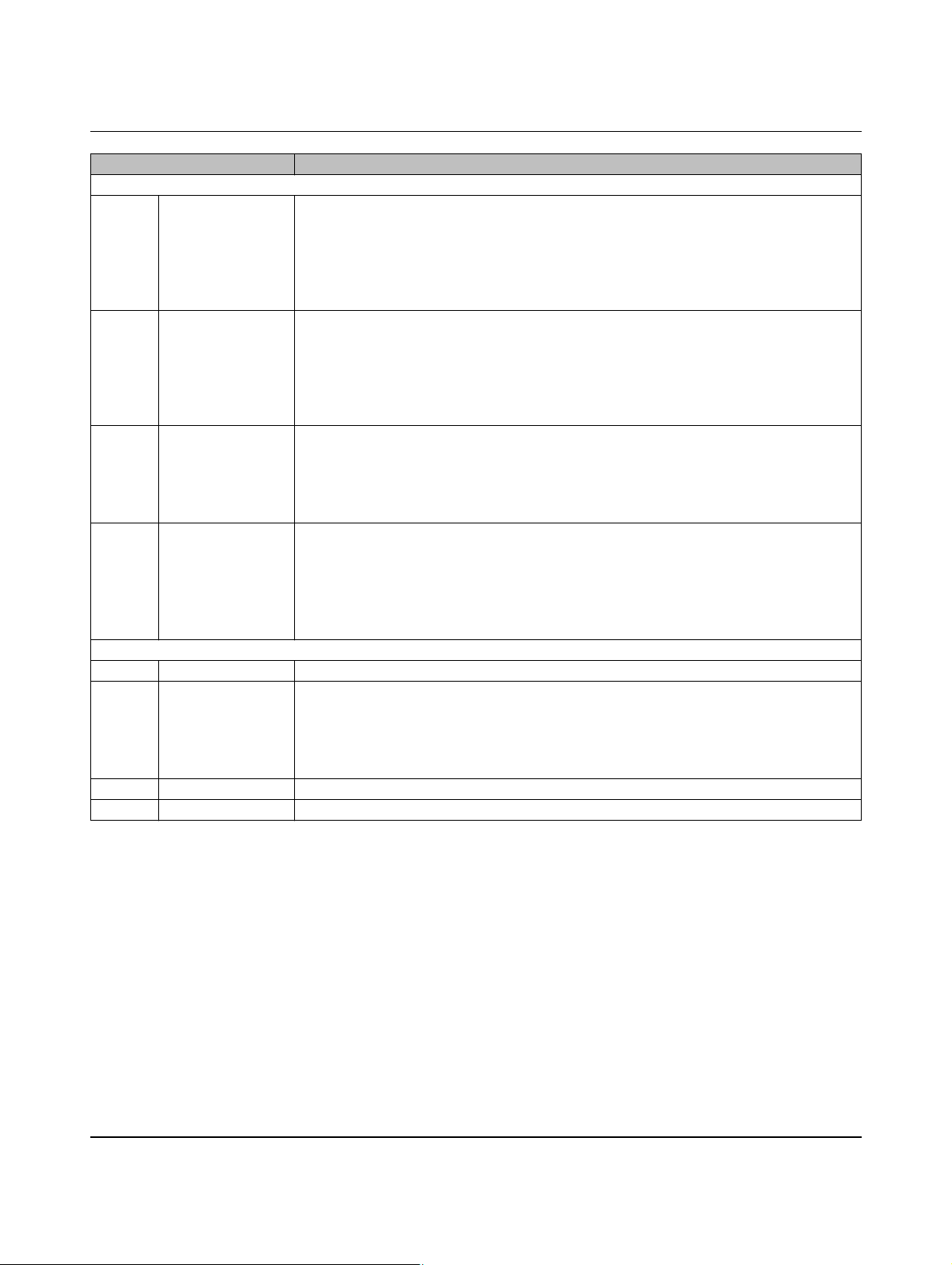
Sequence diagrams for charging process
Vehicle status in Figure 7-1 Charging sequence 1
With status C, charging without ventilation
S1 Status B The charging plug is inserted into the charging socket on the vehicle.
The electric vehicle is detected by means of the CP signal (Control Pilot).
The voltage at CP drops to 9 V, the PWM signal indicates the maximum permissible
charging current to the vehicle.
Digital output CR (Charger Ready) is set.
The CN (CONNECT) LED flashes at a frequency of 2 Hz.
S2 Status C The electric vehicle switches S2 on (see “Control Pilot wiring” on page 22), the voltage at
CP drops to 6 V.
Digital output VR (Vehicle Ready) is set.
The RD (READY) LED is constantly lit.
Relay contacts C1 and C2 are closed.
The charging process is started.
S3 Status B The electric vehicle aborts charging and switches S2 off.
The voltage at CP returns to 9 V.
Digital output VR (Vehicle Ready) is deleted.
The RD (READY) LED is no longer lit.
Relay contacts C1 and C2 are opened again.
S4 Status A The charging plug is no longer connected to the vehicle.
The PWM signal is switched off.
The voltage at CP returns to the idling value of 12 V.
Digital output CR is deleted.
The CN (CONNECT) LED goes out.
The device returns to the initial status.
With status D, charging with ventilation
S5 Status B See above
S6 Status D The electric vehicle switches S2 on, the voltage at CP drops to 3 V.
Digital output VR (Vehicle Ready) is set.
The RD (READY) LED is constantly lit.
Relay contacts C1 and C2 are closed.
Relay contacts V1 and V2 are also closed.
S7 Status B See above
S8 Status A See above
104924_en_04 PHOENIX CONTACT 49
Page 50
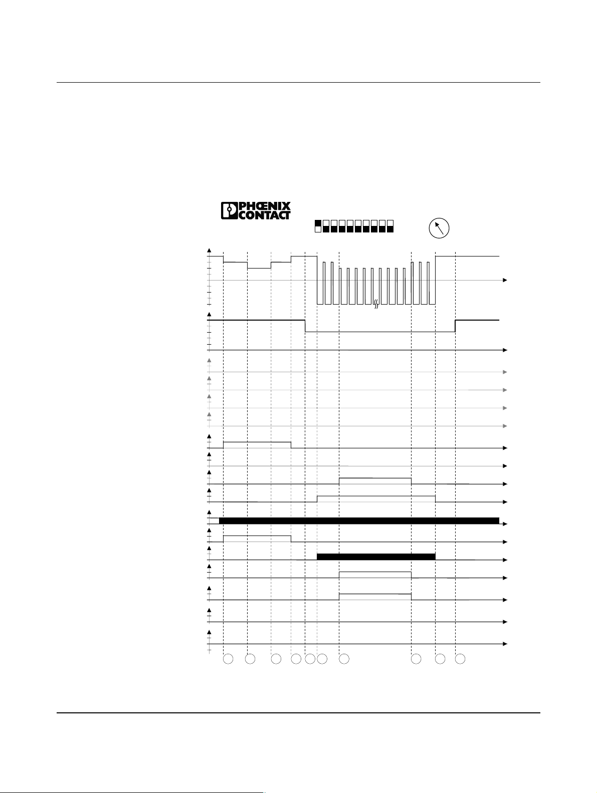
EV Charge Control
DIP 1 = ON PX request, charging cable with plug on the charger (case B)
7.2 Charging sequence 2
The current carrying capacity of the cable and the plugs is determined via the Proximity Plug
and the appropriate resistance circuit in the plug (see “Proximity Plug wiring” on page 21).
If the PRESET CHARGE CURRENT rotary switch is set to a higher current than the Proximity Plug is able to detect, the proximity value limits the current so that the cable or the plugs
cannot be overloaded.
20
16
32
13
63
10
70
6
80
Dig
S9S
8
1
0
-12V
PP[ Ω]
1500
Dig. IN
Dig. OUT
CR
PW
CN
LED
RD
C1/C2
V1/V2
R1-R2
EV Charge Control
IEC 61851-1
Mode 3
CP
12V
9V
6V
3V
0V
∞
680
220
100
0
ML
1
0
XR
1
0
LD
1
0
EN
1
0
ER
1
0
LR
1
0
VR
1
0
1
0
1
0
ER
1
0
1
0
1
0
1
0
1
0
V
in
0
-V
in
S
1
ON
5
1234
S
S
2
3
S4S
S
6
5
678910
S
7
OFF
S
Figure 7-2 Charging sequence 2
PHOENIX CONTACT 104924_en_04
50
Page 51
Sequence diagrams for charging process
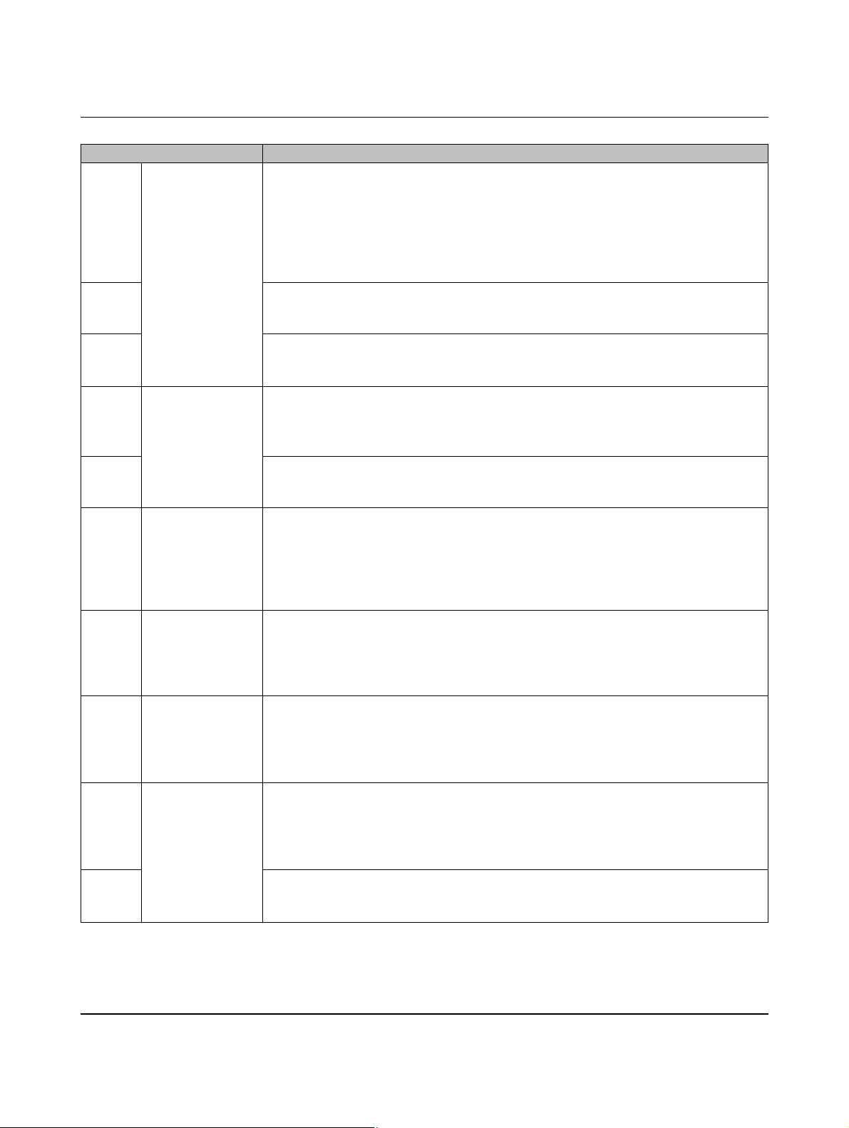
Vehicle status in Figure 7-2 Charging sequence 2
S1 Status E The charging plug is inserted into the charging socket on the vehicle.
The electric vehicle is detected by means of the CP signal (Control Pilot).
The voltage at CP drops to 9 V, a PWM signal is not generated because input PX detects
an open connection.
No Proximity Plug detected in the charging plug or no suitable resistance value.
Digital output ER (Error) is set.
The ER (ERROR) LED is constantly lit.
S2 The electric vehicle switches S2 on (see “Control Pilot wiring” on page 22), the voltage at
CP drops to 6 V.
No changes at the outputs and LEDs.
S3 The electric vehicle aborts charging and switches S2 off.
The voltage at CP returns to 9 V.
No changes at the outputs and LEDs.
S4 Status A The charging plug is no longer connected to the vehicle.
Digital output ER (Error) is deleted.
The ER (ERROR) LED is switched off.
The device returns to the initial status.
S5 The charging cable is connected to the device.
The resistance value of 680 ohms is detected at the Proximity Plug. This value indicates
to the device that the cable or plug has a current carrying capacity of 20 A.
S6 Status B The charging plug is inserted into the charging socket on the vehicle.
The electric vehicle is detected by means of the CP signal (Control Pilot).
The voltage at CP drops to 9 V, the PWM signal indicates the maximum permissible
charging current to the vehicle.
Digital output CR (Charger Ready) is set.
The CN (CONNECT) LED flashes at a frequency of 2 Hz.
S7 Status C The electric vehicle switches S2 on (see “Control Pilot wiring” on page 22), the voltage at
CP drops to 6 V.
Digital output VR (Vehicle Ready) is set.
The RD (READY) LED is constantly lit.
Relay contacts C1 and C2 are closed.
S8 Status B The electric vehicle aborts charging and switches S2 off.
The voltage at CP returns to 9 V.
Digital output VR (Vehicle Ready) is deleted.
The RD (READY) LED is no longer lit.
Relay contacts C1 and C2 are opened again.
S9 Status A The charging plug is no longer connected to the vehicle.
The PWM signal is switched off.
The voltage at CP returns to the idling value of 12 V.
Digital output CR is deleted. The CN LED goes out.
The device returns to the initial status.
S10 The charging cable was removed from the charging station.
The Proximity Plug detects an open input.
The system returns to the initial status.
104924_en_04 PHOENIX CONTACT 51
Page 52

EV Charge Control
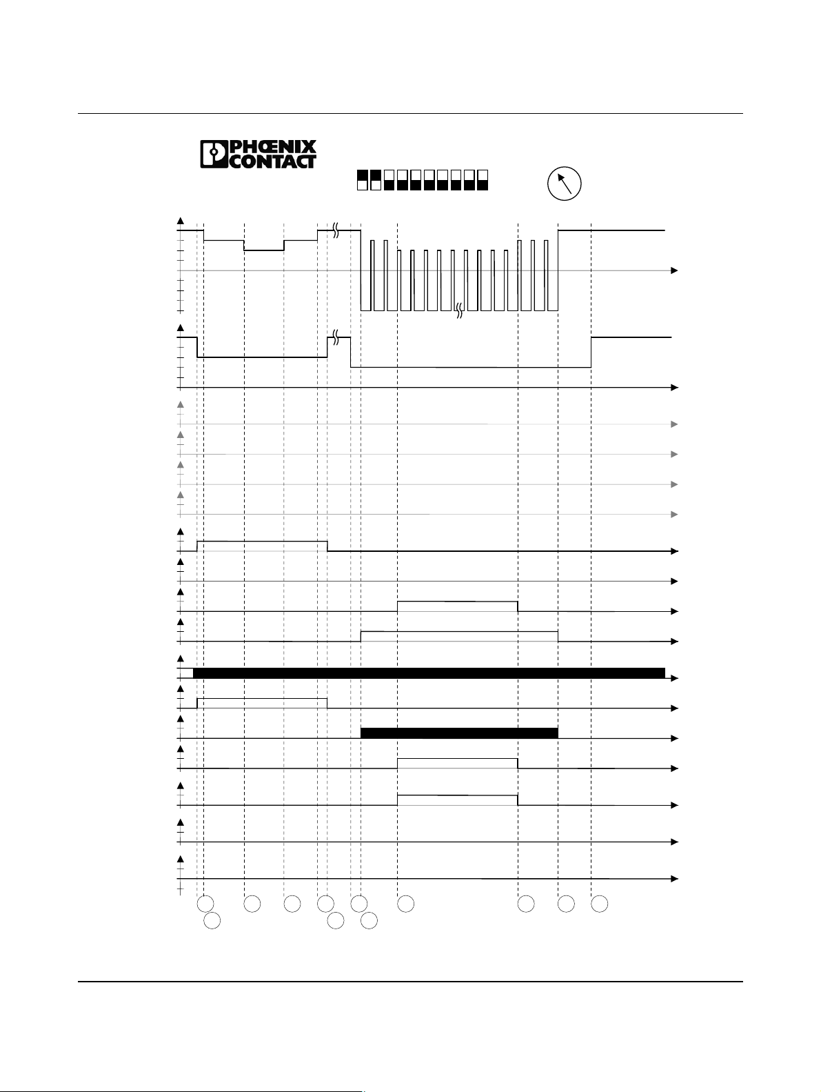
DIP 1 = ON PX request, charging cable with plug on the charger (case B)
DIP 2 = ON Plug/cable with low current carrying capacity is rejected
DIP 3 = ON 13 A plug/cable is rejected
DIP 3 = OFF 13 A and 20 A plug/cable is rejected
7.3 Charging sequence 3
The current carrying capacity of the cable and the plugs is determined via the Proximity Plug
and the appropriate resistance circuit in the plug (see “Proximity Plug wiring” on page 21).
If the PRESET CHARGE CURRENT rotary switch is set to a higher current than the Proximity Plug is able to detect, the proximity value limits the current so that the cable or the plugs
cannot be overloaded.
For values below the limit values, an error is issued and charging cannot be started.
Plugs or cables with a current carrying capacity below 32 A are rejected (13 A and 20 A).
Plugs or cables with a current carrying capacity below 20 A are rejected (13 A).
PHOENIX CONTACT 104924_en_04
52
Page 53
CP
12V
-12V
PP[ Ω]
1500
680
220
100
ML
XR
LD
Dig. IN
EN
ER
LR
VR
Dig. OUT
CR
PW
ER
CN
LED
RD
C1/C2
V1/V2
R1-R2
EV Charge Control
IEC 61851-1
Mode 3
9V
6V
3V
0V
∞
0
1
0
1
0
1
0
1
0
1
0
1
0
1
0
1
0
1
0
1
0
1
0
1
0
1
0
1
0
V
in
0
-V
in
S
1
S
2
Sequence diagrams for charging process
20
16
6
Dig
S11S
32
63
70
80
12
ON
13
OFF
5
1234
S
S
S
4
3
S
7
5
S
S
8
6
678910
S
9
10
S
1
0
Figure 7-3 Charging sequence 3
104924_en_04 PHOENIX CONTACT 53
Page 54
EV Charge Control
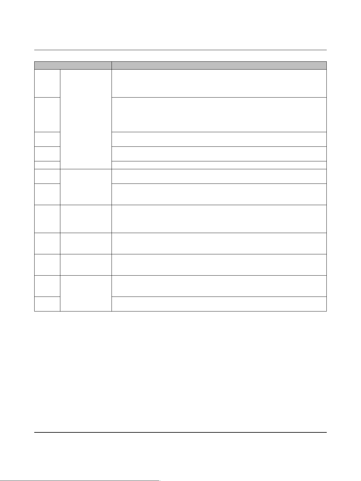
Vehicle status in Figure 7-3 Charging sequence 3
S1 Status E The charging cable is connected to the device. The resistance value of 680 ohms is de-
tected at the Proximity Plug. This value indicates to the device that the cable or plug has
a current carrying capacity of 20 A. Digital output ER (Error) is set. The ER (Error) LED is
constantly lit.
S2 The charging plug is inserted into the charging socket on the vehicle. The electric vehicle
is detected by means of the CP signal (Control Pilot). The voltage at CP drops to 9 V, a
PWM signal is not generated because input PX detects a value that is too low. A resistance value is detected for the Proximity Plug in the charging plug that exceeds the permissible value.
S3 The electric vehicle switches S2 on (see “Control Pilot wiring” on page 22), the voltage at
CP drops to 6 V. No changes at the outputs and LEDs.
S4 The electric vehicle aborts charging and switches S2 off. The voltage at CP returns to 9
V. No changes at the outputs and LEDs.
S5 The charging plug is no longer connected to the vehicle.
S6 Status A The charging cable is no longer connected to the device. The device returns to the initial
status. Digital output ER (Error) is deleted. The ER (Error) LED is switched off.
S7 The charging cable is connected to the device. The resistance value of 220 ohms is de-
tected at the Proximity Plug. This value indicates to the device that the cable or plug has
a current carrying capacity of 32 A.
S8 Status B The charging plug is inserted into the charging socket on the vehicle. The electric vehicle
is detected by means of the CP signal (Control Pilot). The voltage at CP drops to 9 V, the
PWM signal indicates the maximum permissible charging current to the vehicle. Digital
output CR (Charger Ready) is set. The CN (Connect) LED flashes at a frequency of 2 Hz.
S9 Status C The electric vehicle switches S2 on (see “Control Pilot wiring” on page 22), the voltage at
CP drops to 6 V. Digital output VR (Vehicle Ready) is set. The RD (Ready) LED is constantly lit. Relay contacts C1 and C2 are closed.
S10 Status B The electric vehicle aborts charging and switches S2 off. The voltage at CP returns to 9
V. Digital output VR (Vehicle Ready) is deleted. The RD (Ready) LED is no longer lit.
Relay contacts C1 and C2 are opened again.
S11 Status A The charging plug is no longer connected to the vehicle. The PWM signal is switched off.
The voltage at CP returns to the idling value of 12 V. Digital output CR is deleted. The CN
LED goes out. The device returns to the initial status.
S12 The charging cable was removed from the charging station. The Proximity Plug detects
an open input. The system returns to the initial status.
PHOENIX CONTACT 104924_en_04
54
Page 55

Sequence diagrams for charging process
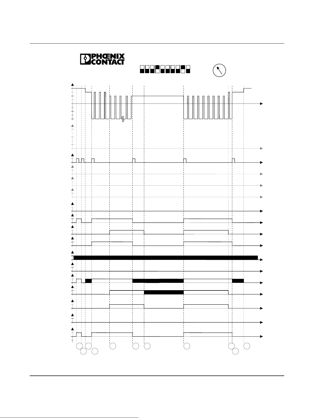
7.4 Charging sequence 4
DIP 1 = OFF No PX request, permanently connected charging cable (case C)
The Proximity Plug is not evaluated. The charging cable is permanently connected to the
charging station.
DIP 4 = ON Locking is executed
DIP 5 = OFF Locking option 0
– Lifting solenoid
– R1-R3 is controlled (R1 at ≤ 24 V) for as long as locking is required
– R2-R4 remains in the initial status (R2 at 0 V) the entire time
During locking, the locking output is constantly supplied with power, which means that the
lifting solenoid is permanently picked up.
DIP 9 = ON Manual locking: input ML is evaluated
Input ML is configured on the controller via pulses using the web interface. Locking is
switched on/off with every pulse at digital input ML. The pulse must be at least 200 ms long.
104924_en_04 PHOENIX CONTACT 55
Page 56
EV Charge Control
CP
12V
9V
6V
3V
0V
-12V
PP[ Ω]
∞
1500
680
220
100
ML
XR
LD
Dig. IN
EN
ER
LR
VR
Dig. OUT
CR
PW
ER
CN
LED
RD
C1/C2
V1/V2
R1-R2
V
-V
EV Charge Control
IEC 61851-1
Mode 3
0
1
0
1
0
1
0
1
0
1
0
1
0
1
0
1
0
1
0
1
0
1
0
1
0
1
0
1
0
in
0
in
S
S
1
3
S2S
4
Figure 7-4 Charging sequence 4
20
16
ON
13
OFF
5
1234
S
5
S6S
7
678910
S
8
10
32
63
70
6
80
Dig
S
S
9
11
S
1
0
PHOENIX CONTACT 104924_en_04
56
Page 57
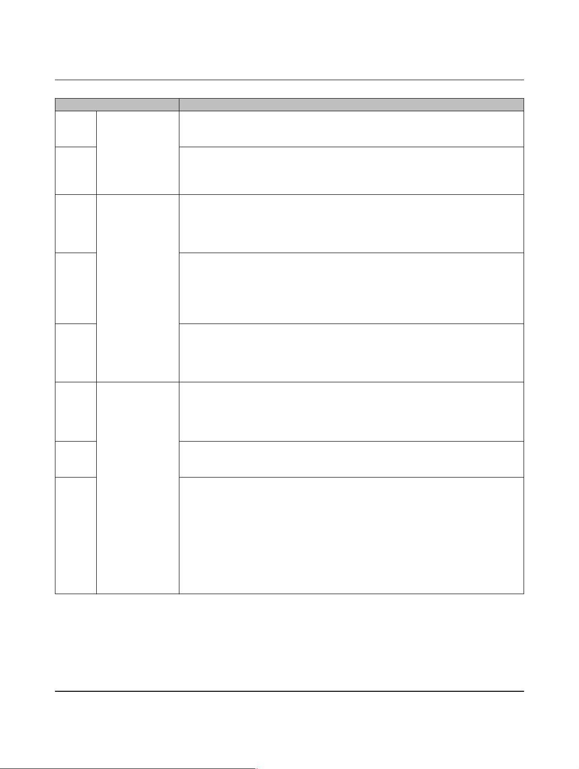
Sequence diagrams for charging process
Vehicle status in Figure 7-4 Charging sequence 4
S1 Status A The system is in the initial status. A signal pulse is generated at digital input ML.
Digital output LR (Locking Request) is switched on.
The CN (Connect) LED lights up. The voltage at locking output R2-R1 is switched on.
S2 A signal pulse is generated at digital input ML.
Digital output LR (Locking Request) is switched off again.
The CN (Connect) LED is no longer lit.
The voltage at locking output R2-R1 is switched off again.
S3 Status B The charging plug is inserted into the charging socket on the vehicle.
The electric vehicle is detected by means of the CP signal (Control Pilot).
The voltage at CP drops to 9 V, a PWM signal is not generated because the plug is not
locked.
The CN (Connect) LED flashes at a frequency of 2 Hz.
S4 A signal pulse is generated at digital input ML.
Digital output LR (Locking Request) is switched on.
The CN (Connect) LED lights up. The voltage at locking output R2-R1 is switched on.
The PWM signal indicates the maximum permissible charging current to the vehicle.
Digital output CR (Charger Ready) is set.
The CN (Connect) LED flashes at a frequency of 2 Hz.
S5 The electric vehicle switches S2 on (see “Control Pilot wiring” on page 22), the voltage at
CP drops to 6 V.
Digital output VR (Vehicle Ready) is set.
The RD (Ready) LED is constantly lit.
Relay contacts C1 and C2 are closed.
S6 Status C A signal pulse is generated at digital input ML.
Digital output LR (Locking Request) is switched off again.
Digital output CR (Charger Ready) is switched off again.
The CN (Connect) LED flashes at 2 Hz again.
The voltage at locking output R2-R1 is switched off again.
S7 After a maximum waiting time of 3 s, relay contacts C1 and C2 are opened again.
Digital output VR (Vehicle Ready) is reset again.
The RD (Ready) LED flashes again.
S8 A signal pulse is generated at digital input ML.
The PWM signal indicates the maximum permissible charging current to the vehicle
again.
Digital output LR (Locking Request) is switched on again.
Digital output VR (Vehicle Ready) is switched on again.
Digital output CR (Charger Ready) is switched on again.
The CN (Connect) LED is constantly lit again.
The RD (Ready) LED is constantly lit again.
Relay contacts C1 and C2 are closed again.
The voltage at locking output R2-R1 is switched on again.
104924_en_04 PHOENIX CONTACT 57
Page 58
EV Charge Control
Vehicle status in Figure 7-4 Charging sequence 4 [...]
S9 Status B The electric vehicle aborts charging and switches S2 off.
The voltage at CP returns to 9 V.
Digital output VR (Vehicle Ready) is deleted.
The RD (Ready) LED is no longer lit.
Relay contacts C1 and C2 are opened again.
S10 A signal pulse is generated at digital input ML.
The PWM signal is switched off.
Digital output LR (Locking Request) is switched off again.
Digital output CR (Charger Ready) is switched off again.
The CN (Connect) LED flashes at 2 Hz again.
The voltage at locking output R2-R1 is switched off again.
S11 Status A The charging plug is no longer connected to the vehicle.
The voltage at CP returns to the idling value of 12 V.
The CN LED goes out. The device returns to the initial status.
PHOENIX CONTACT 104924_en_04
58
Page 59

Sequence diagrams for charging process
7.5 Charging sequence 5
DIP 1 = OFF No PX request, permanently connected charging cable (case C)
The Proximity Plug is not evaluated. The charging cable is permanently connected to the
charging station.
DIP 4 = ON Locking is executed
DIP 5 = OFF Locking option 0
– Lifting solenoid
– R1-R3 is controlled (R1 at ≤ 24 V) for as long as locking is required
– R2-R4 remains in the initial status (R2 at 0 V) the entire time
During locking, the locking output is constantly supplied with power, which means that the
lifting solenoid is permanently picked up.
DIP 9 = OFF Manual locking: input ML is not evaluated
Locking is automatic.
104924_en_04 PHOENIX CONTACT 59
Page 60
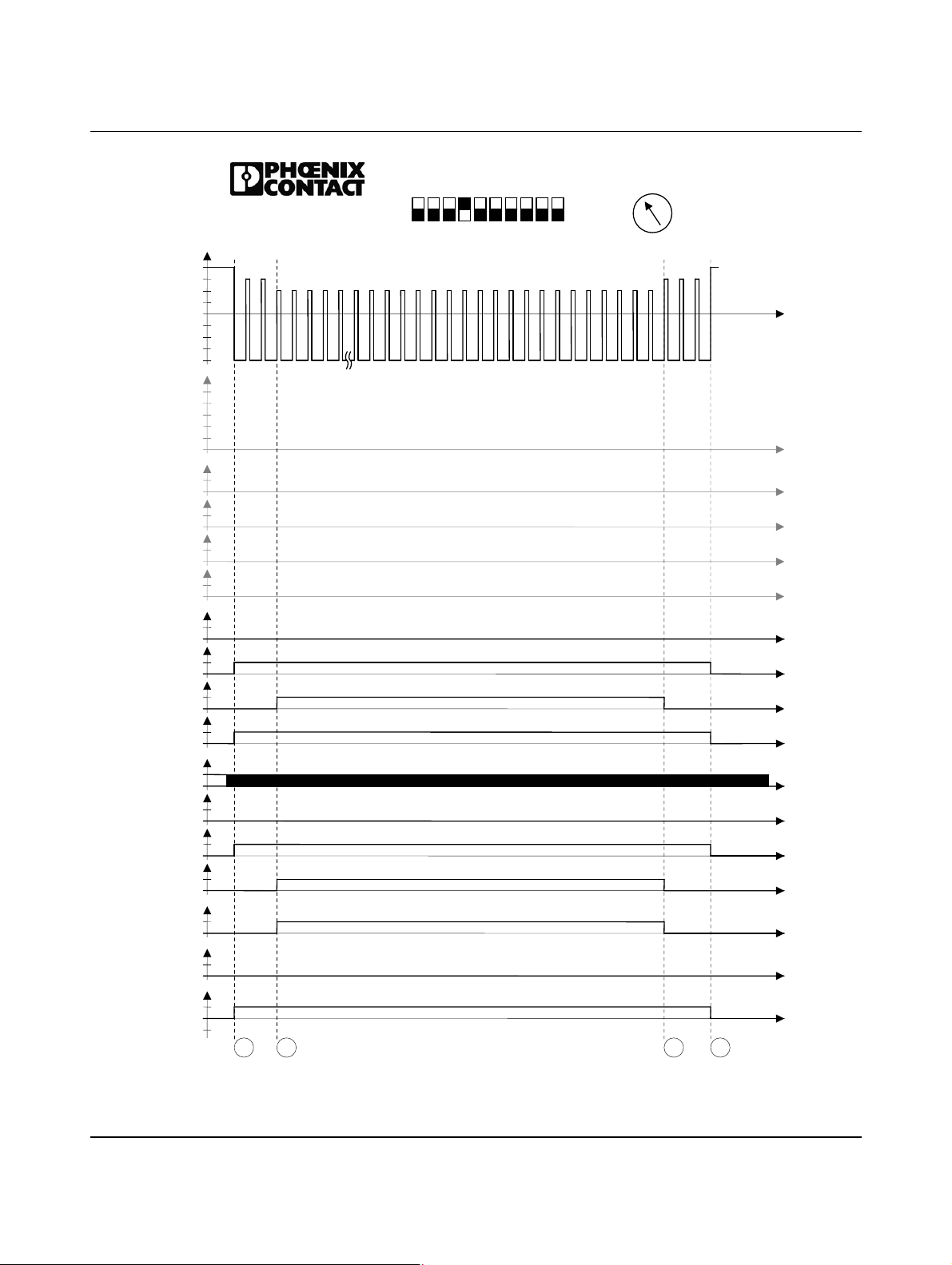
EV Charge Control
CP
12V
9V
6V
3V
0V
-12V
PP[ Ω]
∞
1500
680
220
100
0
ML
1
0
XR
1
0
LD
1
Dig. IN
0
EN
1
0
ER
1
0
LR
1
0
VR
1
Dig. OUT
0
CR
1
0
PW
1
0
ER
1
0
CN
LED
1
0
RD
1
0
C1/C2
1
0
V1/V2
1
0
R1-R2
V
in
0
-V
in
EV Charge Control
IEC 61851-1
Mode 3
S
S
1
2
1234
5
678910
ON
OFF
20
16
13
10
32
63
70
6
80
Dig
S
S
4
3
Figure 7-5 Charging sequence 5
PHOENIX CONTACT 104924_en_04
60
Page 61
Sequence diagrams for charging process
Vehicle status in Figure 7-5 Charging sequence 5
S1 Status B The charging plug is inserted into the charging socket on the vehicle.
The electric vehicle is detected by means of the CP signal (Control Pilot).
The voltage at CP drops to 9 V, the PWM signal indicates the maximum permissible
charging current to the vehicle.
Digital output LR (Locking Request) is set.
Digital output CR (Charger Ready) is set.
The CN (Connect) LED is constantly lit.
The voltage at locking output R2-R1 is switched on.
S2 Status C The electric vehicle switches S2 on (see “Control Pilot wiring” on page 22), the voltage at
CP drops to 6 V.
Digital output VR (Vehicle Ready) is set.
The RD (Ready) LED is constantly lit.
Relay contacts C1 and C2 are closed.
S3 Status B The electric vehicle aborts charging and switches S2 off.
The voltage at CP returns to 9 V.
Digital output VR (Vehicle Ready) is deleted.
The RD (Ready) LED is no longer lit.
Relay contacts C1 and C2 are opened again.
S4 Status A The charging plug is no longer connected to the vehicle.
The PWM signal is switched off.
The voltage at CP returns to the idling value of 12 V.
Digital output CR is deleted.
The CN LED goes out.
The voltage at locking output R2-R1 is switched off again.
The device returns to the initial status.
104924_en_04 PHOENIX CONTACT 61
Page 62

EV Charge Control
DIP 1 = OFF No PX request, permanently connected charging cable (case C)
DIP 4 = ON Locking is executed
DIP 5 = ON Locking option 1
DIP 9 = OFF Manual locking: input ML is not evaluated
7.6 Charging sequence 6
The Proximity Plug is not evaluated. The charging cable is permanently connected to the
charging station.
DC motor: the locking motor is briefly switched on
Locking R1 at ≤ 24 V (R2 remains at 0 V)
Unlocking R2 at ≤ 24 V (R1 remains at 0 V)
To lock, a positive pulse is output at locking output R2-R1. To unlock, a negative
pulse is generated.
Locking is automatic.
PHOENIX CONTACT 104924_en_04
62
Page 63
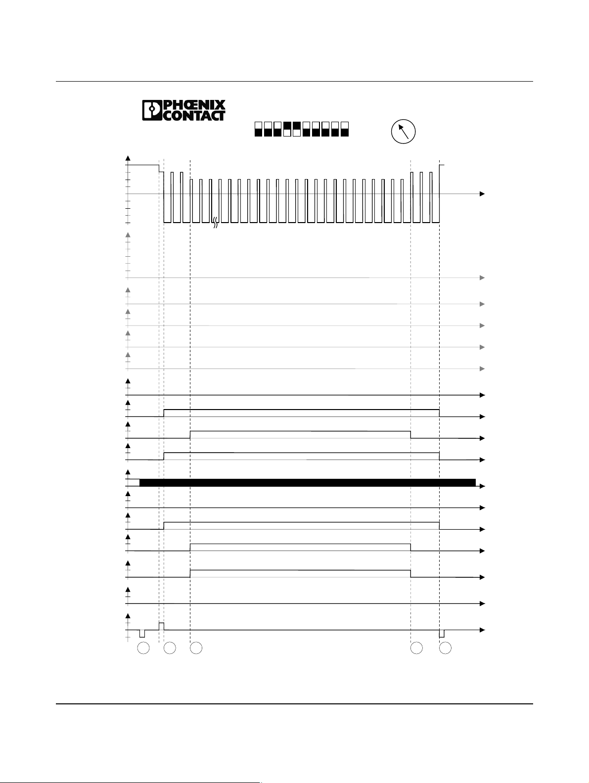
CP
12V
-12V
PP[ Ω]
1500
680
220
100
ML
XR
LD
Dig. IN
EN
ER
LR
VR
Dig. OUT
CR
PW
ER
CN
LED
RD
C1/C2
V1/V2
R1-R2
EV Charge Control
IEC 61851-1
Mode 3
9V
6V
3V
0V
∞
0
1
0
1
0
1
0
1
0
1
0
1
0
1
0
1
0
1
0
1
0
1
0
1
0
1
0
1
0
V
in
0
-V
in
S
S
1
Sequence diagrams for charging process
20
16
ON
13
OFF
5
1234
S
2
3
678910
10
32
63
70
6
80
Dig
S
S
4
5
Figure 7-6 Charging sequence 6
104924_en_04 PHOENIX CONTACT 63
Page 64
EV Charge Control
Vehicle status in Figure 7-6 Charging sequence 6
S1 Status A In this setting, the initialization phase includes an unlocking pulse at locking output R2-R1.
S2 Status B The charging plug is inserted into the charging socket on the vehicle.
The electric vehicle is detected by means of the CP signal (Control Pilot).
The voltage at CP drops to 9 V.
A locking pulse is generated at locking output R2-R1.
After the locking pulse has elapsed, the PWM signal indicates the maximum permissible
charging current to the vehicle.
Digital output LR (Locking Request) is set.
Digital output CR (Charger Ready) is set.
The CN (Connect) LED is constantly lit.
S3 Status C The electric vehicle switches S2 on (see “Control Pilot wiring” on page 22), the voltage at
CP drops to 6 V.
Digital output VR (Vehicle Ready) is set.
The RD (Ready) LED is constantly lit. Relay contacts C1 and C2 are closed.
S4 Status B The electric vehicle aborts charging and switches S2 off.
The voltage at CP returns to 9 V.
Digital output VR (Vehicle Ready) is deleted.
The RD (Ready) LED is no longer lit.
Relay contacts C1 and C2 are opened again.
S5 Status A The charging plug is no longer connected to the vehicle.
The PWM signal is switched off.
The voltage at CP returns to the idling value of 12 V.
Digital output CR is deleted.
The CN (Connect) LED goes out.
An unlocking pulse is generated at locking output R2-R1.
The device returns to the initial status.
PHOENIX CONTACT 104924_en_04
64
Page 65

Sequence diagrams for charging process
7.7 Charging sequence 7
DIP 1 = OFF No PX request, permanently connected charging cable (case C)
The Proximity Plug is not evaluated. The charging cable is permanently connected to the
charging station.
DIP 4 = ON Locking is executed
DIP 5 = ON Locking option 1
DC motor: the locking motor is briefly switched on
Locking R1 at ≤ 24 V (R2 remains at 0 V)
Unlocking R2 at ≤ 24 V (R1 remains at 0 V)
To lock, a positive pulse is output at locking output R2-R1. To unlock, a negative pulse is
generated.
DIP 6 = ON Locking confirmation at input LD is evaluated
The system is expecting locking confirmation at digital input LD.
As long as no confirmation is received regarding locking, the system continues trying to en-
able locking. A locking pulse is sent on each attempt. If unsuccessful, an unlocking pulse is
sent and the sequence is repeated. The times for both pulses and the pause can be set via
the web interface.
DIP 9 = OFF Manual locking: input ML is not evaluated
Locking is automatic.
104924_en_04 PHOENIX CONTACT 65
Page 66
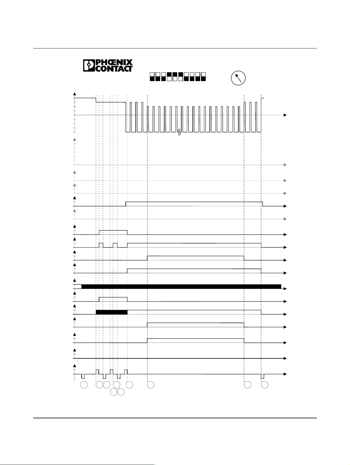
EV Charge Control
CP
12V
9V
6V
3V
0V
-12V
PP[ Ω]
∞
1500
680
220
100
0
ML
1
0
XR
1
0
LD
1
Dig. IN
0
EN
1
0
ER
1
0
LR
1
0
VR
1
Dig. OUT
0
CR
1
0
PW
1
0
ER
1
0
CN
LED
1
0
RD
1
0
C1/C2
1
0
V1/V2
1
0
R1-R2
V
in
0
-V
in
EV Charge Control
IEC 61851-1
Mode 3
S
S
1
S
2
3
S
S
5
S
S
4
6
20
16
ON
13
OFF
5
1234
7
S
8
678910
10
32
63
70
6
80
Dig
S
S
9
10
Figure 7-7 Charging sequence 7
PHOENIX CONTACT 104924_en_04
66
Page 67
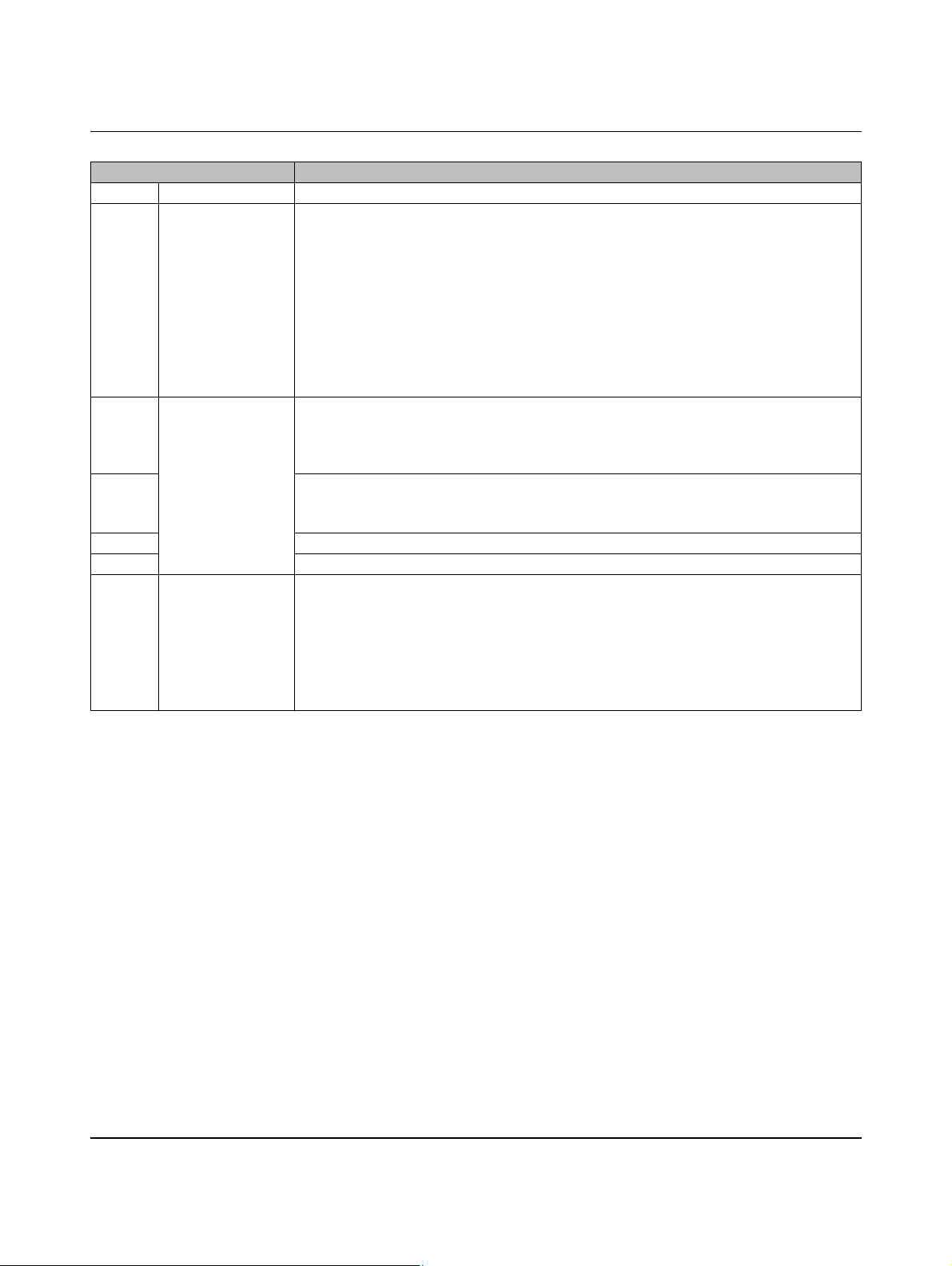
Sequence diagrams for charging process
Vehicle status in Figure 7-7 Charging sequence 7
S1 Status A In this setting, the initialization phase includes an unlocking pulse at locking output R2-R1.
S2 Status B The charging plug is inserted into the charging socket on the vehicle.
The electric vehicle is detected by means of the CP signal (Control Pilot).
The voltage at CP drops to 9 V.
A locking pulse is generated at locking output R2-R1.
A PWM signal is not generated because the plug is not locked.
The CN (Connect) LED flashes at a frequency of 2 Hz.
After the locking pulse has elapsed, digital output LR (Locking Request) is set.
Digital input LD (Lock Detection) is still at 0. An error is therefore now issued.
Digital output ER (Error) is set.
The ER (Error) LED is switched on. The status is set to E.
S3 Status E After the waiting time has elapsed (time between locking cycles, see “Configuration tab”
on page 88), an unlocking pulse is generated at locking output R2-R1.
Digital output LR (Locking Request) is deleted.
The CN (Connect) LED continues flashing.
S4 Digital input LD (Lock Detection) is still set to 0.
Another locking pulse is generated.
The CN (Connect) LED continues flashing.
S5 After the locking pulse has elapsed, digital output LR (Locking Request) is set again.
S6 An unlocking pulse is generated again.
S7 Status B During the new locking pulse, digital input LD (Lock Detection) is set to 1.
After the locking pulse has elapsed, digital output ER (Error) is switched off.
Digital output LR (Locking Request) is switched on.
Digital output CR (Charger Ready) is set.
The ER (Error) LED is switched off.
The CN (Connect) LED is constantly lit.
The PWM signal indicates the maximum permissible charging current to the vehicle.
104924_en_04 PHOENIX CONTACT 67
Page 68
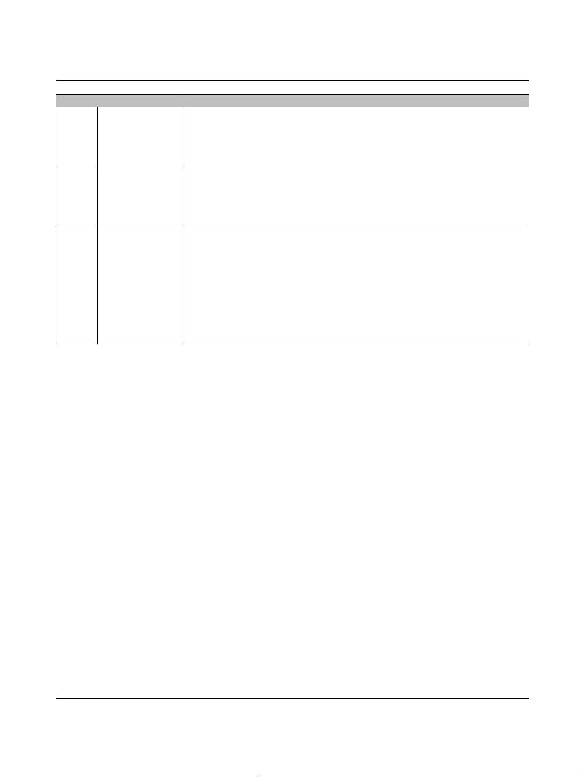
EV Charge Control
Vehicle status in Figure 7-7 Charging sequence 7 [...]
S8 Status C The electric vehicle switches S2 on (see “Control Pilot wiring” on page 22), the voltage at
CP drops to 6 V.
Digital output VR (Vehicle Ready) is set.
The RD (Ready) LED is constantly lit.
Relay contacts C1 and C2 are closed.
S9 Status B The electric vehicle aborts charging and switches S2 off.
The voltage at CP returns to 9 V.
Digital output VR (Vehicle Ready) is deleted.
The RD (Ready) LED is no longer lit.
Relay contacts C1 and C2 are opened again.
S10 Status A The charging plug is no longer connected to the vehicle.
The voltage at CP returns to the idling value of 12 V.
Digital output LR (Locking Request) is switched off.
Digital output CR (Charger Ready) is deleted.
The CN (Connect) LED goes out.
An unlocking pulse is generated at locking output R2-R1.
Digital input LD (Lock Detection) is reset to zero.
The device returns to the initial status.
If the locking confirmation does not work correctly here and digital input LD (Lock Detec-
tion) is not reset to zero, the unlocking and locking cycles are repeated here as well.
PHOENIX CONTACT 104924_en_04
68
Page 69

Sequence diagrams for charging process
7.8 Charging sequence 8
DIP 1 = OFF No PX request, permanently connected charging cable (case C)
The Proximity Plug is not evaluated. The charging cable is permanently connected to the
charging station.
DIP 4 = ON Locking is executed
DIP 5 = OFF Locking option 0
– Lifting solenoid
– R1-R3 is controlled (R1 at ≤ 24 V) for as long as locking is required
– R2-R4 remains in the initial status (R2 at 0 V) the entire time
During locking, the locking output is constantly supplied with power, which means that the
lifting solenoid is permanently picked up.
DIP 7 = ON Enable charging process: input EN is evaluated
The charging process is enabled via digital input EN (Enable).
DIP 9 = OFF Manual locking: input ML is not evaluated
Locking is automatic.
104924_en_04 PHOENIX CONTACT 69
Page 70
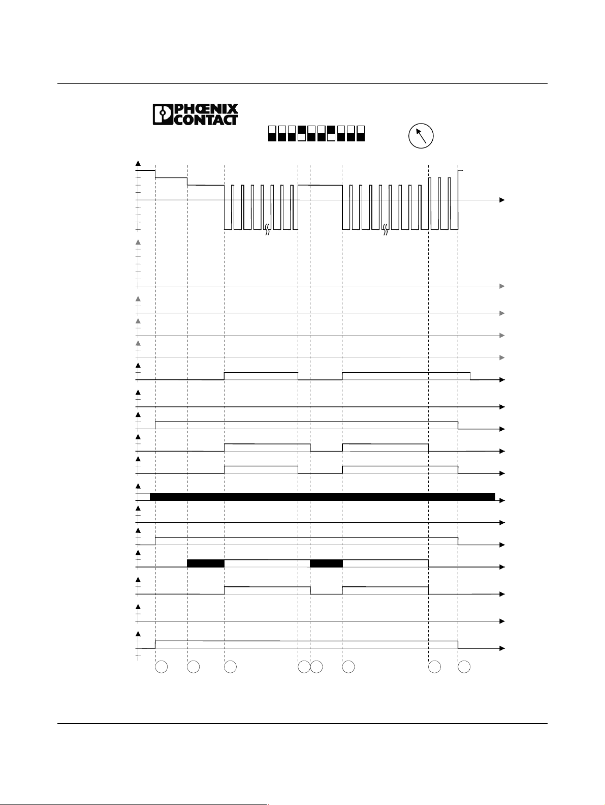
EV Charge Control
CP
12V
9V
6V
3V
0V
-12V
PP[ Ω]
∞
1500
680
220
100
0
ML
1
0
XR
1
0
LD
1
Dig. IN
0
EN
1
0
ER
1
0
LR
1
0
VR
1
Dig. OUT
0
CR
1
0
PW
1
0
ER
1
0
CN
LED
1
0
RD
1
0
C1/C2
1
0
V1/V2
1
0
R1-R2
V
in
0
-V
in
EV Charge Control
IEC 61851-1
Mode 3
S
S
1
2
S
3
1234
5
678910
S4S
5
20
16
ON
13
OFF
10
S
6
32
63
70
6
80
Dig
S
S
8
7
Figure 7-8 Charging sequence 8
PHOENIX CONTACT 104924_en_04
70
Page 71
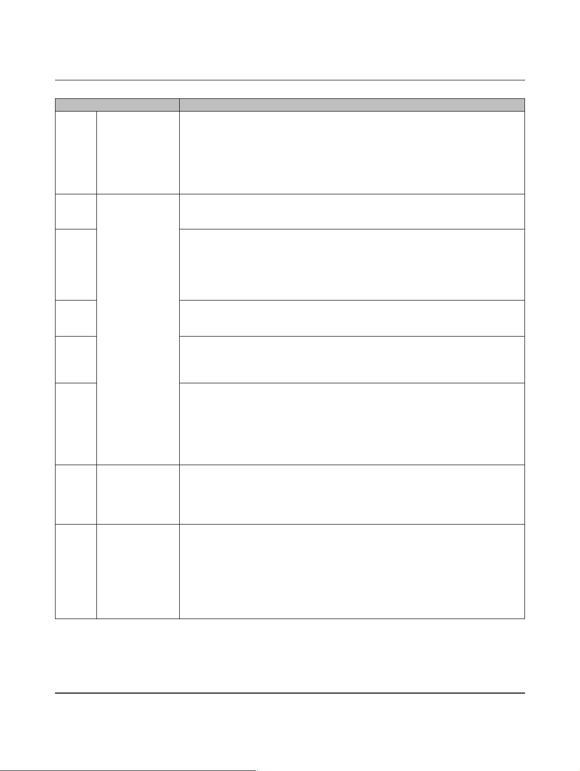
Sequence diagrams for charging process
Vehicle status in Figure 7-8 Charging sequence 8
S1 Status B The charging plug is inserted into the charging socket on the vehicle.
The electric vehicle is detected by means of the CP signal (Control Pilot).
The voltage at CP drops to 9 V.
A PWM signal is not generated because digital input EN (Enable) is still at 0.
Digital output LR (Locking Request) is set.
The CN (Connect) LED is constantly lit.
The voltage at locking output R2-R1 is switched on.
S2 Status C The electric vehicle switches S2 on (see “Control Pilot wiring” on page 22), the voltage at
CP drops to 6 V.
The RD (Ready) LED flashes at a frequency of 2 Hz.
S3 Digital input EN (Enable) is set to 1 by a switch or an external controller.
Digital output VR (Vehicle Ready) is set.
Digital output CR (Charger Ready) is set.
The RD (Ready) LED is constantly lit.
The PWM signal indicates the maximum permissible charging current to the vehicle.
Relay contacts C1 and C2 are switched on.
S4 Digital input EN (Enable) is switched off again.
Digital output CR (Charger Ready) is switched off again.
The PWM signal is switched off.
S5 After a maximum waiting time of 3 s (specified internally), relay contacts C1 and C2 are
opened again.
Digital output VR (Vehicle Ready) is reset again.
The RD (Ready) LED flashes again.
S6 Digital input EN (Enable) is switched on again.
The PWM signal indicates the maximum permissible charging current to the vehicle
again.
Digital output VR (Vehicle Ready) is switched on again.
Digital output CR (Charger Ready) is switched on again.
The RD (Ready) LED is constantly lit again.
Relay contacts C1 and C2 are closed again.
S7 Status B The electric vehicle aborts charging and switches S2 off.
The voltage at CP returns to 9 V.
Digital output VR (Vehicle Ready) is deleted.
The RD (Ready) LED is no longer lit.
Relay contacts C1 and C2 are opened again.
S8 Status A The charging plug is no longer connected to the vehicle.
The PWM signal is switched off.
The voltage at CP returns to the idling value of 12 V.
Digital output LR (Locking Request) is deleted.
Digital output CR (Charger Ready) is deleted.
The CN (Connect) LED goes out.
The voltage at locking output R2-R1 is switched off again.
The device returns to the initial status.
104924_en_04 PHOENIX CONTACT 71
Page 72

EV Charge Control
DIP 1 = OFF No PX request, permanently connected charging cable (case C)
DIP 4 = ON Locking is executed
DIP 5 = OFF Locking option 0
DIP 8 = ON Charging station availability: input XR is evaluated
DIP 9 = OFF Manual locking: input ML is not evaluated
7.9 Charging sequence 9
The Proximity Plug is not evaluated. The charging cable is permanently connected to the
charging station.
– Lifting solenoid
– R1-R3 is controlled (R1 at ≤ 24 V) for as long as locking is required
– R2-R4 remains in the initial status (R2 at 0 V) the entire time
During locking, the locking output is constantly supplied with power, which means that the
lifting solenoid is permanently picked up.
The availability of the device is controlled via digital input XR (External Release).
Locking is automatic.
PHOENIX CONTACT 104924_en_04
72
Page 73
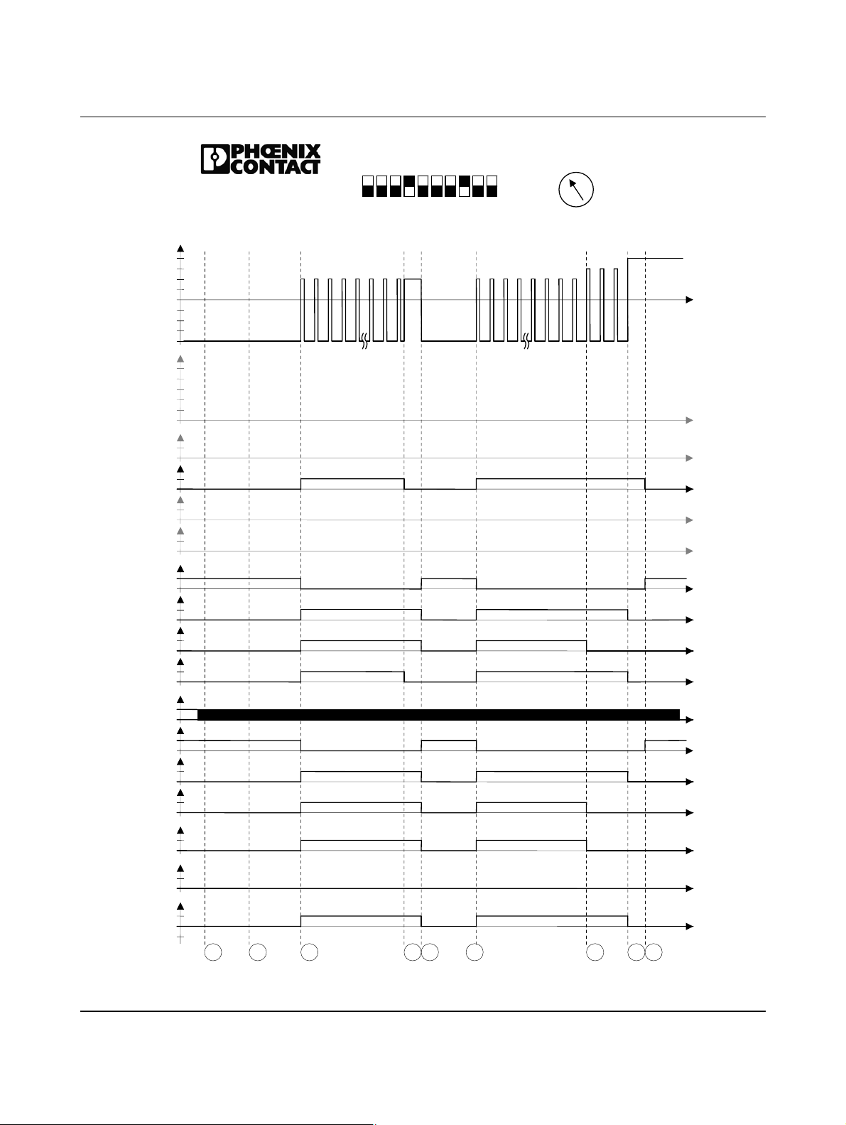
CP
12V
-12V
PP[ Ω]
1500
680
220
100
ML
XR
LD
Dig. IN
EN
ER
LR
VR
Dig. OUT
CR
PW
ER
CN
LED
RD
C1/C2
V1/V2
R1-R2
EV Charge Control
IEC 61851-1
Mode 3
9V
6V
3V
0V
∞
0
1
0
1
0
1
0
1
0
1
0
1
0
1
0
1
0
1
0
1
0
1
0
1
0
1
0
1
0
V
in
0
-V
in
S
1
Sequence diagrams for charging process
20
16
ON
13
OFF
5
1234
S
2
S
3
678910
S4S
5
S
6
10
32
63
70
6
80
Dig
S
S
7
S
8
9
Figure 7-9 Charging sequence 9
104924_en_04 PHOENIX CONTACT 73
Page 74
EV Charge Control
Vehicle status in Figure 7-9 Charging sequence 9
S1 Status F The charging plug is inserted into the charging socket on the vehicle.
The voltage at CP is set to -12 V because digital input XR (External Release) is not set by
a switch or an external controller.
A PWM signal is not generated.
Digital output ER (Error) is set. The ER (ERROR) LED lights up.
S2 The electric vehicle switches S2 on (see “Control Pilot wiring” on page 22).
S3 Status C Digital input XR (External Release) was set to 1.
Digital output ER (Error) is reset. Digital output LR (Locking Request) is set.
Digital output VR (Vehicle Ready) is set.
Digital output CR (Charger Ready) is set.
The ER (ERROR) LED is switched off.
The CN (CONNECT) LED is switched on.
The RD (READY) LED is switched on.
The PWM signal indicates the maximum permissible charging current to the vehicle.
Relay contacts C1 and C2 are switched on.
The locking voltage at locking output R2-R1 is switched on.
S4 Digital input XR (External Release) was deleted.
The PWM signal at the CP signal is switched off.
Digital output CR (Charger Ready) is switched off again.
S5 Status F After a maximum waiting time of 3 s (specified internally), the CP signal is set to -12 V.
Digital output ER (Error) is set.
Digital output LR (Locking Request) is deleted.
Digital output VR (Vehicle Ready) is deleted.
The ER (ERROR) LED is switched on.
The CN (CONNECT) LED is switched off.
The RD (READY) LED is switched off.
Relay contacts C1 and C2 are switched off.
The locking voltage at locking output R2-R1 is switched off.
S6 Status C Digital input XR (External Release) was reset to 1.
Digital output ER (Error) is deleted.
Digital output LR (Locking Request) is set.
Digital output VR (Vehicle Ready) is set.
Digital output CR (Charger Ready) is set.
The ER (ERROR) LED is switched off.
The CN (CONNECT) LED is switched on.
The RD (READY) LED is switched on.
The PWM signal indicates the maximum permissible charging current to the vehicle.
Relay contacts C1 and C2 are switched on.
The locking voltage at locking output R2-R1 is switched on.
PHOENIX CONTACT 104924_en_04
74
Page 75
Sequence diagrams for charging process
Vehicle status in Figure 7-9 Charging sequence 9 [...]
S7 Status B The electric vehicle aborts charging and switches S2 off.
The voltage at CP returns to 9 V.
Digital output VR (Vehicle Ready) is deleted.
The RD (READY) LED is no longer lit.
Relay contacts C1 and C2 are opened again.
S8 Status A The charging plug is no longer connected to the vehicle.
The PWM signal is switched off.
The voltage at CP returns to the idling value of 12 V.
Digital output LR (Locking Request) is deleted.
Digital output CR (Charger Ready) is deleted.
The CN (CONNECT) LED goes out.
The voltage at locking output R2-R1 is switched off again.
The device returns to the initial status.
S9 Status F The voltage at CP is set to -12 V because digital input XR (External Release) is deleted
by a switch or an external controller.
Digital output ER (Error) is set.
The ER (ERROR) LED lights up.
104924_en_04 PHOENIX CONTACT 75
Page 76

EV Charge Control
DIP 1 = OFF No PX request, permanently connected charging cable (case C)
DIP 4 = ON Locking is executed
DIP 5 = OFF Locking option 0
DIP 7 = ON Enable charging process: input EN is evaluated
DIP 9 = OFF Manual locking: input ML is evaluated
DIP 10 = ON Enable bit in Modbus register is evaluated
7.10 Charging sequence 10
The Proximity Plug is not evaluated. The charging cable is permanently connected to the
charging station.
– Lifting solenoid
– R1-R3 is controlled (R1 at ≤ 24 V) for as long as locking is required
– R2-R4 remains in the initial status (R2 at 0 V) the entire time
During locking, the locking output is constantly supplied with power, which means that the
lifting solenoid is permanently picked up.
The charging process is enabled via digital input EN (Enable).
Input ML is configured on the controller via pulses using the web interface. Locking is
switched on/off with every pulse at digital input ML. The pulse must be at least 200 ms long.
The charging process is enabled with register address 400 via Ethernet access with Mod-
bus TCP or via the web interface. Both enabling options (input EN and address 400) are
ORed.
PHOENIX CONTACT 104924_en_04
76
Page 77
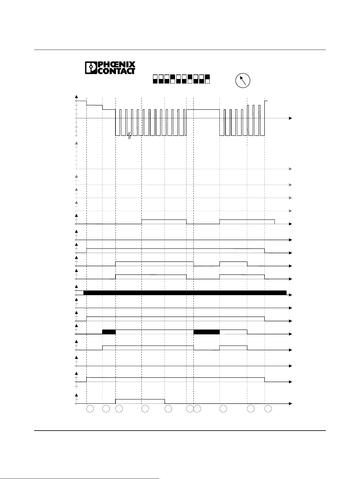
CP
12V
-12V
PP[ Ω]
1500
ML
XR
Dig. IN
EN
ER
VR
Dig. OUT
CR
PW
ER
CN
LED
RD
C1/C2
V1/V2
R1-R2
R10
EV Charge Control
IEC 61851-1
Mode 3
9V
6V
3V
0V
∞
680
220
100
0
1
0
1
0
LD
1
0
1
0
1
0
LR
1
0
1
0
1
0
1
0
1
0
1
0
1
0
1
0
1
0
V
in
0
-V
in
1
0
S
1
5
S2S
1234
S
3
4
S
5
678910
Figure 7-10 Charging sequence 10
S6S
Sequence diagrams for charging process
20
16
ON
13
OFF
10
7
S
8
32
63
70
6
80
Dig
S
S
1
9
0
104924_en_04 PHOENIX CONTACT 77
Page 78
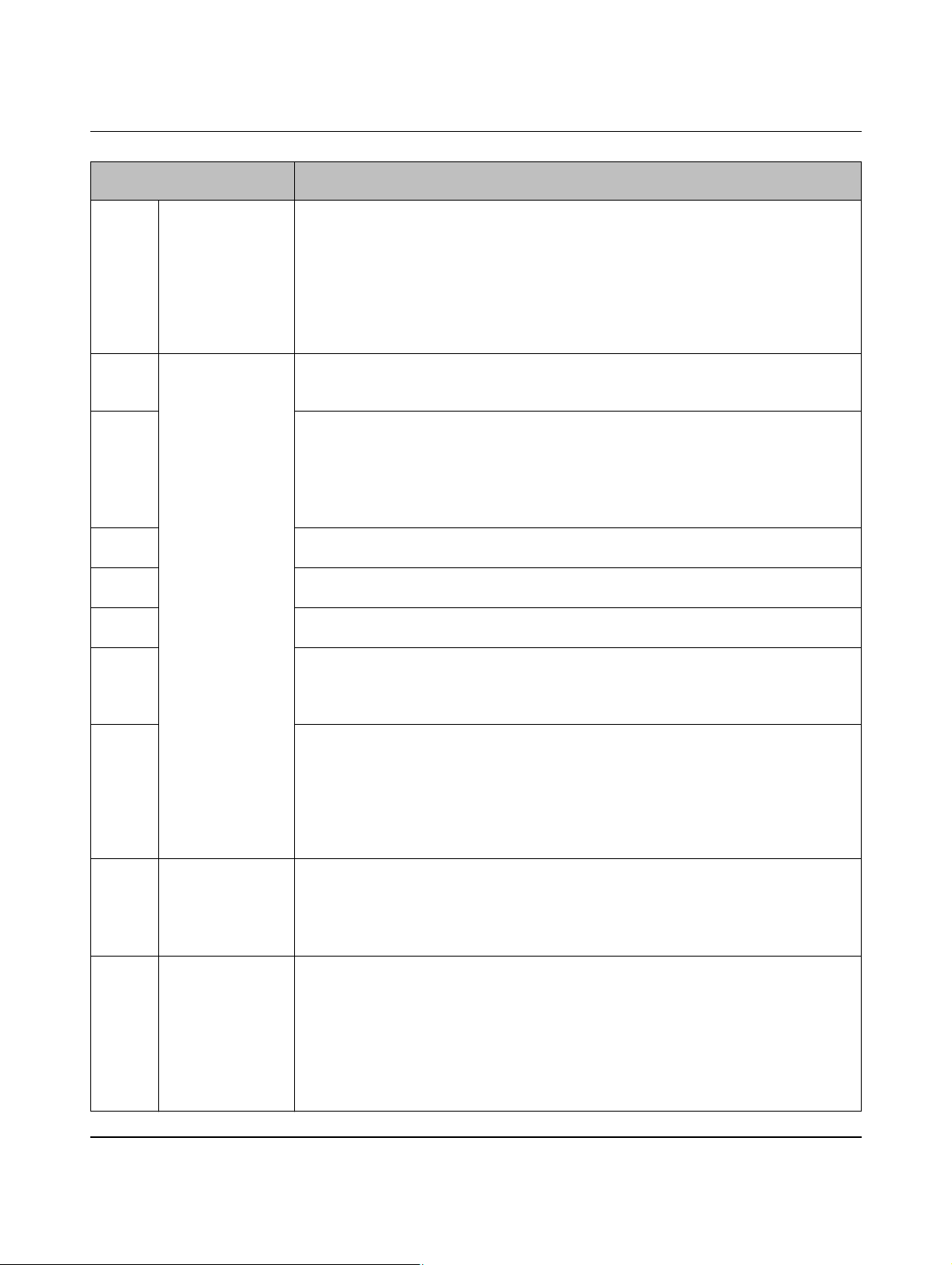
EV Charge Control
Vehicle status in
Charging sequence 10
Figure 7-10
S1 Status B The charging plug is inserted into the charging socket on the vehicle.
The electric vehicle is detected by means of the CP signal (Control Pilot).
The voltage at CP drops to 9 V.
A PWM signal is not generated because digital input EN (Enable) and register address
400 are still at 0.
Digital output LR (Locking Request) is set.
The CN (Connect) LED is constantly lit.
The voltage at locking output R2-R1 is switched on.
S2 Status C The electric vehicle switches S2 on (see “Control Pilot wiring” on page 22), the voltage at
CP drops to 6 V.
The RD (Ready) LED flashes at a frequency of 2 Hz.
S3 Register address 400 is set to 1 by means of write access.
Digital output VR (Vehicle Ready) is set.
Digital output CR (Charger Ready) is set.
The RD (Ready) LED is constantly lit.
The PWM signal indicates the maximum permissible charging current to the vehicle.
Relay contacts C1 and C2 are switched on.
S4 Digital input EN (Enable) is set to 1 by a switch or an external controller.
No changes are made due to ORing.
S5 Register address 400 is set to 0 by means of write access.
No changes are made due to ORing.
S6 Digital input EN (Enable) is switched off again.
Digital output CR (Charger Ready) is switched off again.
S7 After a maximum waiting time of 3 s (specified internally), relay contacts C1 and C2 are
opened again.
Digital output VR (Vehicle Ready) is reset again.
The RD (Ready) LED flashes again.
S8 Digital input EN (Enable) is switched on again.
The PWM signal indicates the maximum permissible charging current to the vehicle
again.
Digital output VR (Vehicle Ready) is switched on again.
Digital output CR (Charger Ready) is switched on again.
The RD (Ready) LED is constantly lit again.
Relay contacts C1 and C2 are closed again.
S9 Status B The electric vehicle aborts charging and switches S2 off.
The voltage at CP returns to 9 V.
Digital output VR (Vehicle Ready) is deleted.
The RD (Ready) LED is no longer lit.
Relay contacts C1 and C2 are opened again.
S10 Status A The charging plug is no longer connected to the vehicle.
The PWM signal is switched off.
The voltage at CP returns to the idling value of 12 V.
Digital output LR (Locking Request) is deleted.
Digital output CR (Charger Ready) is deleted.
The CN (Connect) LED goes out.
The voltage at locking output R2-R1 is switched off again.
The device returns to the initial status.
PHOENIX CONTACT 104924_en_04
78
Page 79

Sequence diagrams for charging process
7.11 Charging sequence 11
DIP 1 = ON PX request, charging cable with plug on the charger (case B)
The current carrying capacity of the cable and the plugs is determined via the Proximity Plug
and the appropriate resistance circuit in the plug (see “Proximity Plug wiring” on page 21).
If the PRESET CHARGE CURRENT rotary switch is set to a higher current than the Prox-
imity Plug is able to detect, the proximity value limits the current so that the cable or the plugs
cannot be overloaded.
DIP 2 = ON Plug/cable with low current carrying capacity is rejected
For values below the limit values, an error is issued and charging cannot be started.
DIP 3 = ON 13 A plug/cable is rejected
Plugs or cables with a current carrying capacity below 32 A are rejected (13 A and 20 A).
DIP 3 = OFF 13 A and 20 A plug/cable is rejected
Plugs or cables with a current carrying capacity below 20 A are rejected (13 A).
DIP 4 = ON Locking is executed
DIP 5 = ON Locking option 1
DC motor: the locking motor is briefly switched on
Locking R1 at ≤ 24 V (R2 remains at 0 V)
Unlocking R2 at ≤ 24 V (R1 remains at 0 V)
To lock, a positive pulse is output at locking output R2-R1. To unlock, a negative pulse is
generated.
DIP 6 = ON Locking confirmation at input LD is evaluated
The system is expecting locking confirmation at digital input LD.
As long as no confirmation is received regarding locking, the system continues trying to en-
able locking. A locking pulse is sent on each attempt. If unsuccessful, an unlocking pulse is
sent and the sequence is repeated. The times for both pulses and the pause can be set via
the web interface.
DIP 7 = ON Enable charging process: input EN is evaluated
The charging process is enabled via digital input EN (Enable).
DIP 8 = ON Charging station availability: input XR is evaluated
The availability of the device is controlled via digital input XR (External Release).
DIP 9 = ON Manual locking: input ML is evaluated
Input ML is configured on the controller via pulses using the web interface. Locking is
switched on/off with every pulse at digital input ML. The pulse must be at least 200 ms long.
DIP 10 = ON Enable bit in Modbus register is evaluated
The charging process is enabled with register address 400 via Ethernet access with Mod-
bus TCP or via the web interface. Both enabling options (input EN and address 400) are
ORed.
104924_en_04 PHOENIX CONTACT 79
Page 80
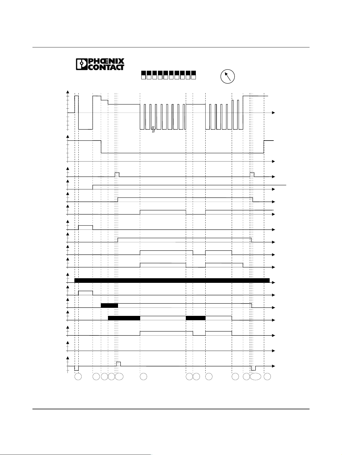
EV Charge Control
CP
12V
9V
6V
3V
0V
-12V
PP[ Ω]
∞
1500
680
220
100
0
ML
1
0
XR
1
0
LD
1
Dig. IN
0
EN
1
0
ER
1
0
LR
1
0
VR
1
Dig. OUT
0
CR
1
0
PW
1
0
ER
1
0
CN
LED
1
0
RD
1
0
C1/C2
1
0
V1/V2
1
0
R1-R2
V
in
0
-V
in
EV Charge Control
IEC 61851-1
Mode 3
1
S2S3S
S
4
5-7
S
1234
S
8
5
678910
ON
OFF
S9S10S
20
16
6
32
80
Dig
S12S13S
63
70
S
14-16
17
13
10
11
Figure 7-11 Charging sequence 11
PHOENIX CONTACT 104924_en_04
80
Page 81
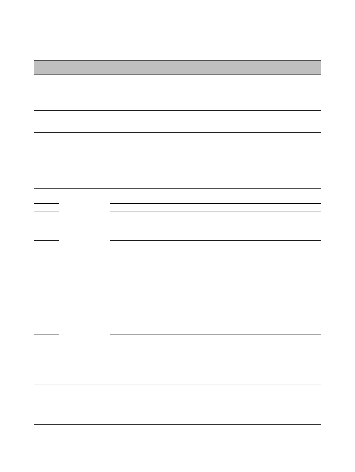
Sequence diagrams for charging process
Vehicle status in
Charging sequence 11
Figure 7-11
S1 Status F Following the initialization phase, the voltage at CP is set to -12 V because digital input XR
(External Release) is not set by a switch or an external controller.
A PWM signal is not generated.
Digital output ER (Error) is set.
The ER (ERROR) LED lights up.
S2 Status A Digital input XR (External Release) was set to 1.
Digital output ER (Error) is reset.
The ER (ERROR) LED is switched off.
S3 Status B The charging cable is connected to the charging station.
Input PX (Proximity Plug) detects a resistance value of 220 ohms, which represents a current carrying capacity of 32 A.
The charging plug is inserted into the charging socket on the vehicle. The electric vehicle
is detected by means of the CP signal (Control Pilot).
The voltage at CP drops to 9 V, a PWM signal is not generated because the plug is not
locked.
The CN (CONNECT) LED flashes at a frequency of 2 Hz.
S4 Status C The electric vehicle switches S2 on, the voltage at CP drops to 6 V.
The RD (READY) LED flashes at a frequency of 2 Hz.
S5 A 0 is generated at digital input ML (Manual Lock) by a button or an external controller.
S6 The locking pulse is issued at locking output R2-R1.
S7 The locking mechanism indicates correct locking via digital input LD (Lock Detection).
Digital output LR (Locking Request) is switched on. The CN (Connect) LED is constantly
lit.
S8 Digital input EN (Enable) is set to 1 by a switch or an external controller.
The PWM signal indicates the maximum permissible charging current to the vehicle.
Digital output VR (Vehicle Ready) is set.
Digital output CR (Charger Ready) is set.
The RD (READY) LED is constantly lit.
Relay contacts C1 and C2 are switched on.
S9 Digital input EN (Enable) is switched off again.
Digital output CR (Charger Ready) is switched off again.
The PWM signal is switched off.
S10 After a maximum waiting time of 3 s (specified internally), relay contacts C1 and C2 are
opened again.
Digital output VR (Vehicle Ready) is reset again.
The RD (READY) LED flashes again.
S11 Digital input EN (Enable) is switched on again.
The PWM signal indicates the maximum permissible charging current to the vehicle
again.
Digital output VR (Vehicle Ready) is switched on again.
Digital output CR (Charger Ready) is switched on again.
The RD (READY) LED is constantly lit again.
Relay contacts C1 and C2 are closed again.
104924_en_04 PHOENIX CONTACT 81
Page 82
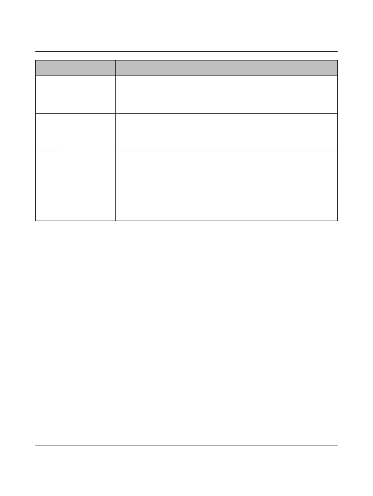
EV Charge Control
Vehicle status in
Charging sequence 11 [...]
Figure 7-11
S12 Status B The electric vehicle aborts charging and switches S2 off.
The voltage at CP returns to 9 V.
Digital output VR (Vehicle Ready) is deleted.
The RD (READY) LED is no longer lit.
Relay contacts C1 and C2 are opened again.
S13 Status A The charging plug is no longer connected to the vehicle.
The PWM signal is switched off.
The voltage at CP returns to the idling value of 12 V.
Digital output LR (Locking Request) is deleted.
Digital output CR (Charger Ready) is deleted.
S14 A pulse is generated at digital input ML (Manual Lock) by a button or an external control-
ler.
S15 The unlocking pulse is issued at locking output R2-R1.
Digital output LR (Locking Request) is switched off.
The CN (CONNECT) LED is switched off.
S16 The locking mechanism indicates the absence of locking via digital input LD (Lock Detec-
tion).
S17 The charging cable is removed from the charging station.
Input PX (Proximity Plug) detects an open input.
PHOENIX CONTACT 104924_en_04
82
Page 83

Configuration via web interface
8 Configuration via web interface
8.1 Connecting to the device
• Connect the charging controller to a PC on which a browser is installed via the Ethernet
connection.
The following are examples of browsers that you can use:
– Mozilla Firefox 17.0 or later
The software is pre-installed.
IP address 192.168.0.8 is set by default upon delivery of the system.
However, the IP address can also be assigned via DHCP (see “Network tab” on page 91).
If a DHCP server is found with this setting, the system can be found in two ways:
– Using the MAC address specified on the rating plate
– If a DNS server is available, the system can be addressed using the device name. The
preset device name is EVCC_1.
The system can be reached using the preset IP address if the following settings have been
made on your computer (example procedure for Windows 7):
Setting up the IP address 1. In your system select “Network and Sharing Center” under “Start, Control Panel,
Network and Internet”.
2. From the connections available, select the one that is connected to the EV Charge Control charging controller.
3. Click on “Properties”.
4. Select “Internet Protocol Version 4 (TCP/IPv4)” and click on “Properties”.
5. Here you can assign a suitable IP address to your computer, enabling you to use it to
establish a direct connection to the charging controller.
6. You can now access and configure the system via your browser.
To do this, enter
7. Depending on the setup and network, in the address line of your browser you can also
enter the device name or another IP address you have set via the browser.
http://192.168.0.8 in the address line of your browser.
104924_en_04 PHOENIX CONTACT 83
Page 84
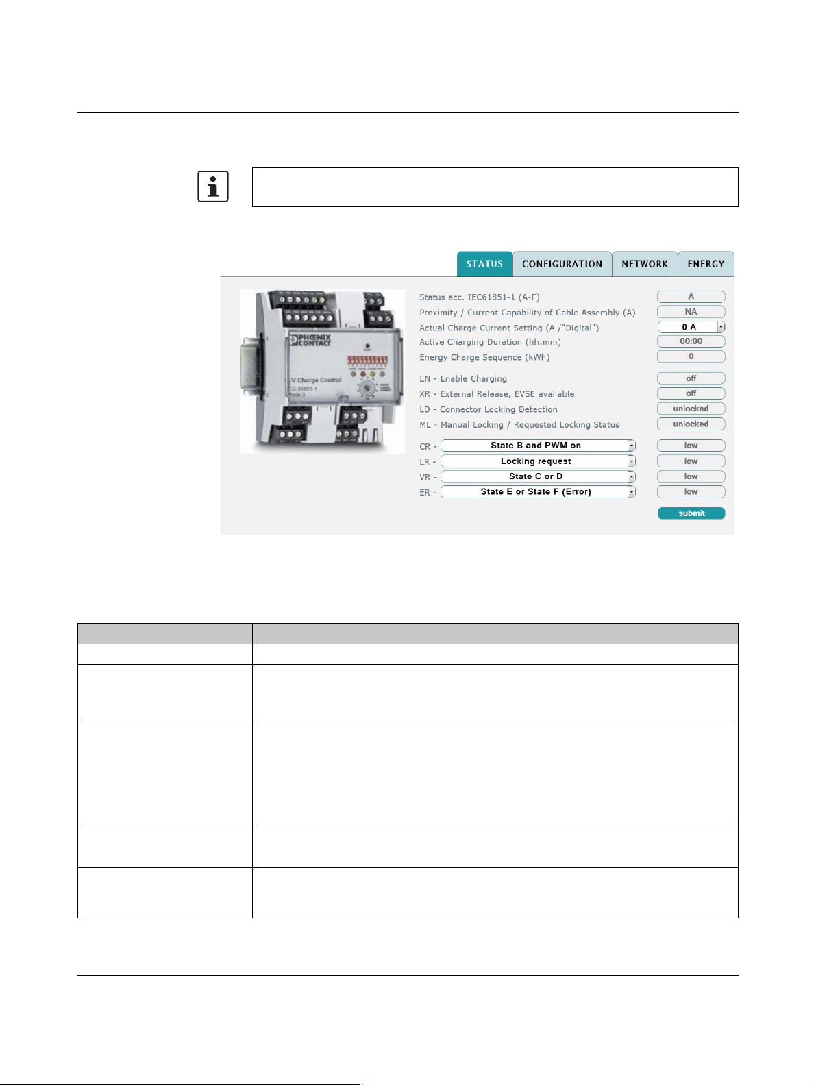
EV Charge Control
8.2 Status tab
In order to safely transmit the changes, you must click on the “submit” button within the
polling cycle (10 seconds). Otherwise, the original values will be restored.
Figure 8-1 “Status” web interface
Table 8-1 “Status” tab
Parameter Description
Status acc. IEC 61851 (A-F) Current status of the vehicle. “A” to “F” is possible.
Proximity / Current Capability of Cable Assembly (A)
Actual Charge Current Setting (A / “Digital”)
Active Charging Duration
(hh:mm)
Energy Charge Sequence
(kWh)
Displays the current carrying capacity of the plug and cable determined by means of the
PX signal (Proximity Plug).
If DIP 1 is set to OFF, “NA” appears in this field because the value cannot be determined.
Represents the actual permissible charging current that is set and determined by the de-
vice.
The permissible current values can be set via the selection box. The current values that
are offered can be reduced using the PRESET CHARGE CURRENT rotary switch, the
Proximity Plug or simplified mode. Any changes must be confirmed by clicking on the
“submit” button.
Displays the charging time for the current charging process.
The value is reset again at the start of each charging process.
Displays the charged power of the current charging process. The value is reset again at
the start of each charging process. This display is only visible if a power meter is connected.
PHOENIX CONTACT 104924_en_04
84
Page 85
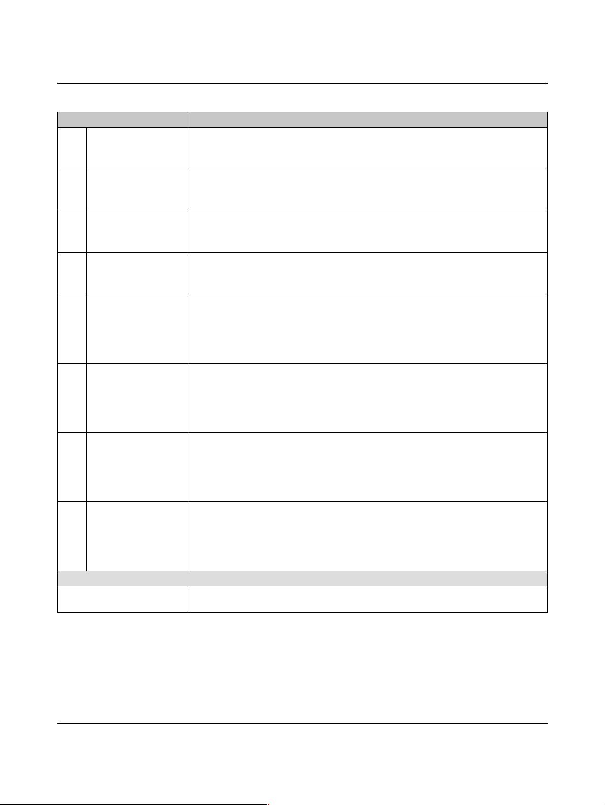
Configuration via web interface
Table 8-1 “Status” tab [...]
Parameter Description
EN Enable Charging Displays the status of digital input EN.
– “on” stands for logic 1 or 24 V at the input
– “off” stands for logic 0 or 0 V at the input
XR External Release,
EVSE available
Displays the status of digital input XR.
– “on” stands for logic 1 or 24 V at the input
– “off” stands for logic 0 or 0 V at the input
LD Connector Locking
Detection
Displays the status of digital input LD.
– “locked” stands for logic 1 or 24 V at the input
– “unlocked” stands for logic 0 or 0 V at the input
ML Manual Locking /
Requested Locking
Status
Displays the status of digital input ML.
– “locked” stands for logic 1 or 24 V at the input
– “unlocked” stands for logic 0 or 0 V at the input
CR Displays the status of digital output CR.
– “high” stands for logic 1 at the output
– “low” stands for logic 0 or 0 V at the output
The assignment of the outputs to the signals that are to be output can be programmed via
the pull-down menu. The default value is “PWM on”.
LR Displays the status of digital output LR.
– “high” stands for logic 1 at the output
– “low” stands for logic 0 or 0 V at the output
The assignment of the outputs to the signals that are to be output can be programmed via
the pull-down menu. The default value is “Locking request”.
VR Displays the status of digital output VR.
– “high” stands for logic 1 at the output
– “low” stands for logic 0 or 0 V at the output
The assignment of the outputs to the signals that are to be output can be programmed via
the pull-down menu. The default value is “State C or D”.
ER Displays the status of digital output ER.
– “high” stands for logic 1 at the output
– “low” stands for logic 0 or 0 V at the output
The assignment of the outputs to the signals that are to be output can be programmed via
the pull-down menu. The default value is “State E or State F (Error)”.
Button
submit The modified configuration data is transmitted to the charging controller using this button,
otherwise the changes to the settings are not applied.
104924_en_04 PHOENIX CONTACT 85
Page 86
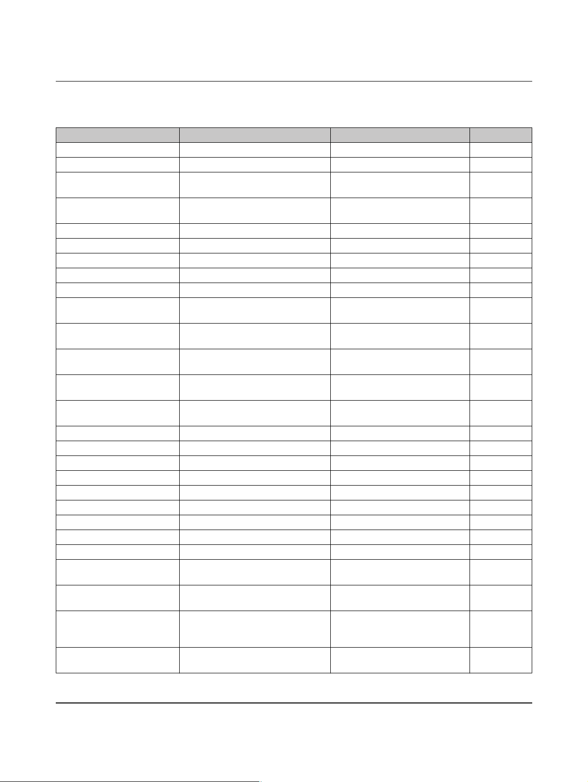
EV Charge Control
The following options can be set for the outputs using the pull-down menu.
Table 8-2 “Status” tab, options for outputs CR, LR, VR, and ER
Display in pull-down menu Output High Output Low Default
State A Device in status A Device in status B - F
State B Device in status B Device in status A or C - F
State B and PWM on Device in status B and PWM ON Device in status A, C - F or PWM
OFF
State B and PWM off Device in status B and PWM OFF Device in status A, C - F or PWM
ON
State C Device in status C Device in status A - B or D - F
State D Device in status D Device in status A - C or E - F
State E Device in status E Device in status A - D or F
State F Device in status F Device in status A - E
State A or State B Device in status A or B Device in status C - F
State A or State B and
PWM on
State A or State B and
PWM off
State A or State B or
Device in status A or B and PWM ON Device in status C - F or B and
PWM OFF
Device in status A or B and PWM OFF Device in status C - F or B and
PWM ON
Device in status A - C Device in status D - F
State C
State A or State B or
Device in status A - B or D Device in status C or E - F
State D
State A or State B or
Device in status A - D Device in status E - F
State C or State D
State E or State F (Error) Device in status E - F Device in status A - D Default for ER
State C or D Device in status C or D Device in status A, B, E, F Default for VR
PWM on Device PWM ON Device in status A, PWM OFF, E, F Default for CR
Valid Proximity Plug Valid PX value detected Invalid PX value detected
Invalid Proximity Plug Invalid PX value detected Valid PX value detected
13 A at Proximity Plug 13 A plug detected at PX OFF for all other values
20 A at Proximity Plug 20 A plug detected at PX OFF for all other values
32 A at Proximity Plug 32 A plug detected at PX OFF for all other values
63 A at Proximity Plug 63 A plug detected at PX OFF for all other values
13 A or 20 A at Proximity
13 A or 20 A plug detected at PX OFF for all other values
Plug
13 A or 20 A or 32 A at
13 A or 20 A or 32 A plug detected at PXOFF for all other values
Proximity Plug
Rejected plug with low
current carrying capacity
Device rejects EV charging because
current carrying capacity of charging
OFF for all other PP values
cable is too low
Contactor C1C2 on Device switches the “charging con-
Otherwise OFF
tactor” relay ON
PHOENIX CONTACT 104924_en_04
86
Page 87
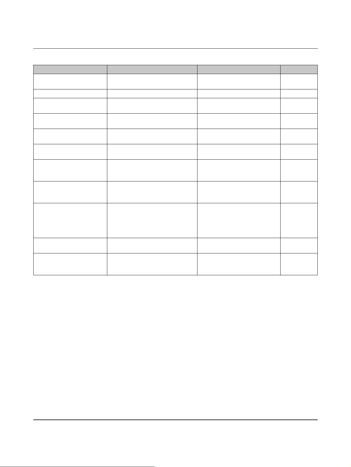
Configuration via web interface
Table 8-2 “Status” tab, options for outputs CR, LR, VR, and ER [...]
Display in pull-down menu Output High Output Low Default
Ventilation V1V2 on Device switches the “ventilator” relay ONOtherwise OFF
Locking request Locking is active Locking is not active Default for LR
Register Output1 The “Output1” register has been set
via Modbus (logic 1)
Register Output2 The “Output2” register has been set
via Modbus (logic 1)
Register Output3 The “Output3” register has been set
via Modbus (logic 1)
Register Output4 The “Output4” register has been set
via Modbus (logic 1)
Overcurrent Detection A vehicle has been charged with a
higher current than specified by the
PWM signal
State A/B Voltage Detection In status A or B, a connected energy
meter still measured a voltage
> 200 V after switch off
Contactor Monitoring The contactor monitoring has de-
tected a status that could lead to live
voltage at the charging station, even
The “Output1” register has been
deleted via Modbus
The “Output2” register has been
deleted via Modbus
The “Output3” register has been
deleted via Modbus
The “Output4” register has been
deleted via Modbus
The specifications of the PWM signal have been observed by the vehicle
In status A and B, a connected energy meter did not measure a voltage > 200 V after switch off
The contactor monitoring has not
detected any statuses out of the
ordinary.
with the charging station in the off
state.
State D rejected A vehicle that charges in status D has
been detected and rejected
State B or State C or
State D
A vehicle is connected to the charging
station.
No vehicle that charges in status D
detected
No vehicle is connected to the
charging station or there is an error
(status A, E, or F).
104924_en_04 PHOENIX CONTACT 87
Page 88
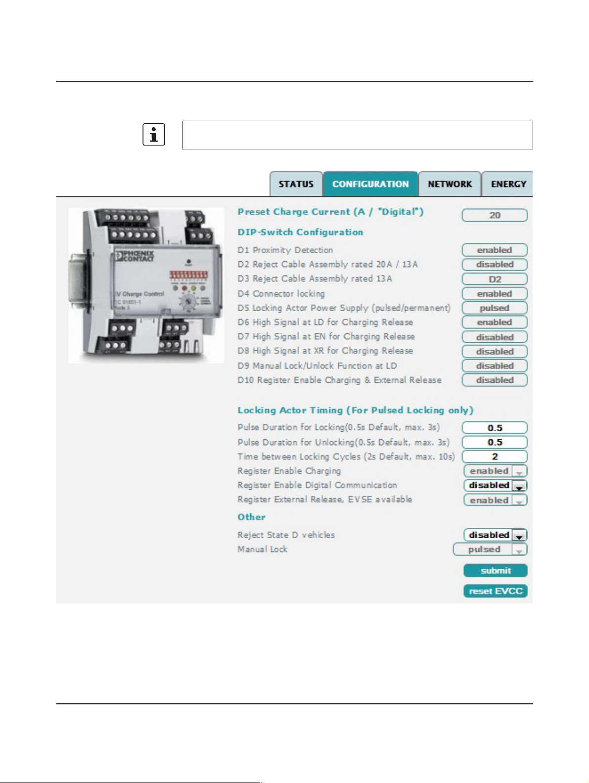
EV Charge Control
8.3 Configuration tab
In order to safely transmit the changes, you must click on the “submit” button within the
polling cycle (10 seconds). Otherwise, the original values will be restored.
Figure 8-2 “Configuration” web interface
PHOENIX CONTACT 104924_en_04
88
Page 89
Configuration via web interface
Table 8-3 “Configuration” tab
Parameter Description
Preset Charge Current
(A / “Digital”)
The maximum permissible charging current is displayed here, which is set via the PRESET CHARGE CURRENT rotary switch on the front of the device.
DIP-Switch Configuration The device settings are displayed here as they are set on the front of the device using the
DIP switches (see item 19 in “Function elements” on page 11).
D1 Proximity Detection Select Proximity Plug request
D2 Reject Cable Assem-
≤ 20 A or ≤ 13 A current carrying capacity selection (only when DIP 1 is set to ON)
bly rated 20A / 13A
D3 Reject Cable Assem-
≤ 13 A current carrying capacity selection (only when DIP 1 is set to ON)
bly rated 13A
D4 Connector locking Select locking function
D5 Locking Actor Power
Select locking option (only when DIP 4 is set to ON)
Supply (pulsed/permanent)
D6 High Signal at LD for
Locking confirmation (only when DIP 4 is set to ON)
Charging Release
D7 High Signal at EN for
Select enabling function for charging process
Charging Release
D8 High Signal at XR for
Select charging station availability
Charging Release
D9 Manual Lock/Unlock
Select manual locking option (only when DIP 4 is set to ON)
Function at LD
D10 Register Enable
Charging & External
Release
Locking Actor Timing (For
Pulsed Locking only)
Pulse Duration for Locking
(0.5s Default, max. 3s)
Pulse Duration for Unlocking (0.5s Default, max. 3s)
Time between Locking
Cycles (2s Default, max.
10s)
Select enabling function via register address 400
Can be enabled via Modbus or web interface.
Here you can set the times the system uses for the locking output signals when the
“pulsed” locking option (D5) is set.
Duration of the locking pulse
Any changes must be confirmed by clicking on the “submit” button.
Duration of the unlocking pulse
Any changes must be confirmed by clicking on the “submit” button.
Waiting time between the locking and unlocking pulses if errors occur while the automatic
locking option is running.
Any changes must be confirmed by clicking on the “submit” button.
104924_en_04 PHOENIX CONTACT 89
Page 90
EV Charge Control
Table 8-3 “Configuration” tab [...]
Parameter Description
Register Enable Charging This field corresponds to register address 400. The charging process is enabled with the
“enable” setting if this option was selected via DIP 10.
Any changes must be confirmed by clicking on the “submit” button.
Register Enable Digital
Communication
The “Digital Communication” function is selected in this field. This selection corresponds
to the “Dig” setting on the PRESET CHARGE CURRENT rotary switch.
Any changes must be confirmed by clicking on the “submit” button.
Register External Release,
EVSE available
This field corresponds to digital input XR (External Release) and is ORed to it. If the field
is set to “enabled” OR digital input XR is set to High, the system is enabled.
Any changes must be confirmed by clicking on the “submit” button.
Other
Reject State D vehicles If this function is set to “enabled”, vehicles that charge in status D are rejected. (Status D
= positive value of PWM signal on the Control Pilot = 3 V.) The device enters an error status and can only be reset via status A. (Status A = disconnection of the vehicle from the
charging station.)
Manual Lock This selection box is only active when DIP 9 = ON.
This function can be used to select whether digital input ML is operated with pulses
(“pulsed”) or continuous signals (“permanent”).
– “pulsed”: with each pulse (> 200 ms) at input ML, it switches between locking and un-
locking.
– “permanent”: locked as long as a logic 1 is present at input ML; unlocked on a logic 0.
Buttons
submit The modified configuration data is transmitted to the charging controller using this button,
otherwise the changes to the settings are not applied.
reset EVCC This button restarts the charging controller.
PHOENIX CONTACT 104924_en_04
90
Page 91
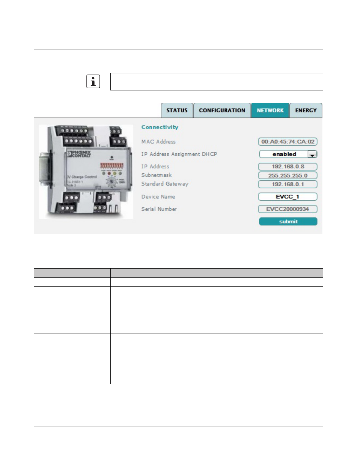
Configuration via web interface
8.4 Network tab
In order to safely transmit the changes, you must click on the “submit” button within the
polling cycle (10 seconds). Otherwise, the original values will be restored.
Figure 8-3 “Network” web interface
Table 8-4 “Network” tab
Parameter Description
MAC Address MAC address of the device. The MAC address is fixed, unique, and cannot be changed.
IP Address Assignment
DHCP
This field allows you to choose between a fixed IP address and a DHCP request.
– “disabled”: a fixed IP address including subnet mask and standard gateway is set.
– “enabled”: a DHCP request is executed. If there is a DHCP server in the network, an
IP address is assigned to the device. If there is also a DNS server in the network, the
device can be accessed via the device name.
Any changes must be confirmed by clicking on the “submit” button.
IP Address Here you can set the IP address of the device which is used if there is no active DHCP ser-
vice.
Any changes must be confirmed by clicking on the “submit” button.
Subnetmask Here you can set the subnet mask of the device which is used if there is no active DHCP
service.
Any changes must be confirmed by clicking on the “submit” button.
104924_en_04 PHOENIX CONTACT 91
Page 92
EV Charge Control
Table 8-4 “Network” tab [...]
Parameter Description
Standard Gateway Here you can set the IP address of the standard gateway which is used if there is no active
DHCP service.
Any changes must be confirmed by clicking on the “submit” button.
Device Name You can access the system via the device name if a DNS server in the network can resolve
the name. The default value is “EVCC_1”.
Any changes must be confirmed by clicking on the “submit” button.
Serial Number The serial number of the device is fixed, unique, and cannot be changed.
Button
submit The modified configuration data is transmitted to the charging controller using this button,
otherwise the changes to the settings are not applied.
PHOENIX CONTACT 104924_en_04
92
Page 93
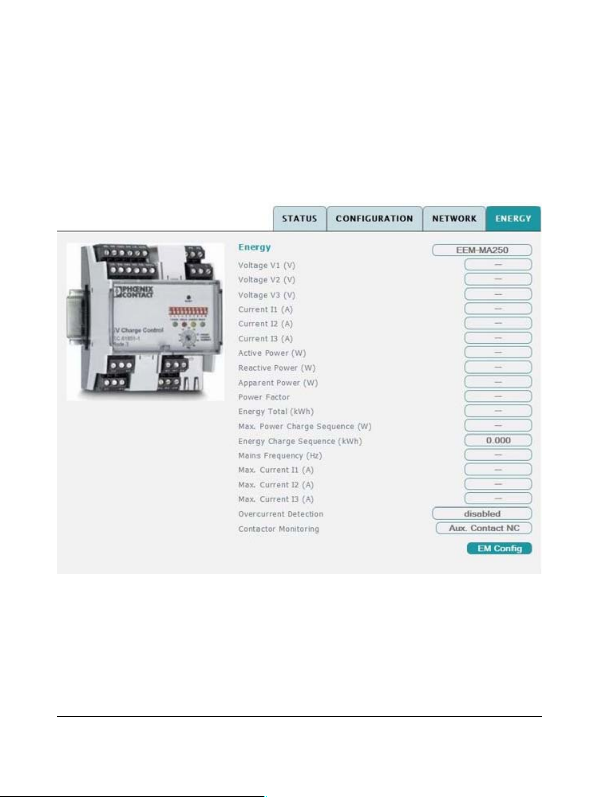
Configuration via web interface
8.5 Energy tab
Energy meters which support the Modbus RTU protocol can be connected to the charging
controller via the RS-485 interface. The energy meters must provide Integer data with a
maximum of two data words in Little Endian or Big Endian format.
The measured values that are relevant for the charging process are cyclically read by the
charging controller and displayed in the web interface. In addition, they are provided in the
Modbus TCP registers for reading via the Ethernet interface.
Figure 8-4 “Energy” web interface
The configuration of the energy meters allows measured values to be assigned to the display fields in various ways.
Deviations from the table are possible and may be necessary for some meters. It depends
on the data that is provided by the meter. Please also refer to the documentation for the energy meter used.
104924_en_04 PHOENIX CONTACT 93
Page 94
EV Charge Control
Table 8-5 “Energy” tab
Display value Description
Energy
Voltage V1 - V3 (V) Voltage at the three phases in volts, either as outer conductor voltage or voltage to neutral
conductor, depends on the configuration and the data provided by the meter.
Current I1 - I3 (A) Current of the three phases in A
Active Power (W) Real power in watts
Reactive Power (W) Reactive power
Apparent Power (W) Apparent power
Power Factor Power factor/cos phi
Energy Total (kWh) Reading value in kWh of a meter that cannot be reset
Max. Power Charge
Maximum power of the current charging process in W
Sequence (W)
Energy Charge Sequence
Energy transmitted for the current charging process in kWh
(kWh)
Mains Frequency (Hz) Current mains frequency
Max. Current I1 - I3 (A) Maximum measured current on conductors L1 - L3 during the current charging process
Overcurrent Detection Monitoring of charging currents
– “enabled”: the charging controller compares the measured charging currents with the
maximum permissible charging currents specified by the PWM signal on the
Control Pilot.
In the event of an overcurrent of 10% ... 20%, the charging process is aborted after
100 s.
In the event of an overcurrent > 20%, it is switched off after 10 s. The charging controller enters an error state, the reset condition is status A.
– “disabled”: no monitoring of charging currents.
Contactor Monitoring With this function, it is possible to check whether the load contactor switched the input free
of voltage after the end of the charging process. If an error is detected, the charging control
goes to error status. The error status can only be canceled by resetting the charging controller.
The following configurations are possible:
– “disabled”: the load contactor is not checked.
– “Voltage Measurement”: By means of an attached measuring device, it is possible to
measure the voltage at the charging station output. In order to use this configuration,
the dynamic response of the connected meter must be known. The charging controller evaluates the voltage that is read after four polling cycles (“Polling cycle” parameter).
– “Aux. Contact NO”/”Aux. Contact NC”: The charging controller evaluates the N/O or
N/C auxiliary contacts of the load contactor. The evaluation takes place 500 ms after
the load contactor is switched off. The length of time can be adjusted using the Modbus register 519.
Buttons
EM Config The configuration for the connection between the meter and charging controller can be ac-
cessed using this button.
PHOENIX CONTACT 104924_en_04
94
Page 95
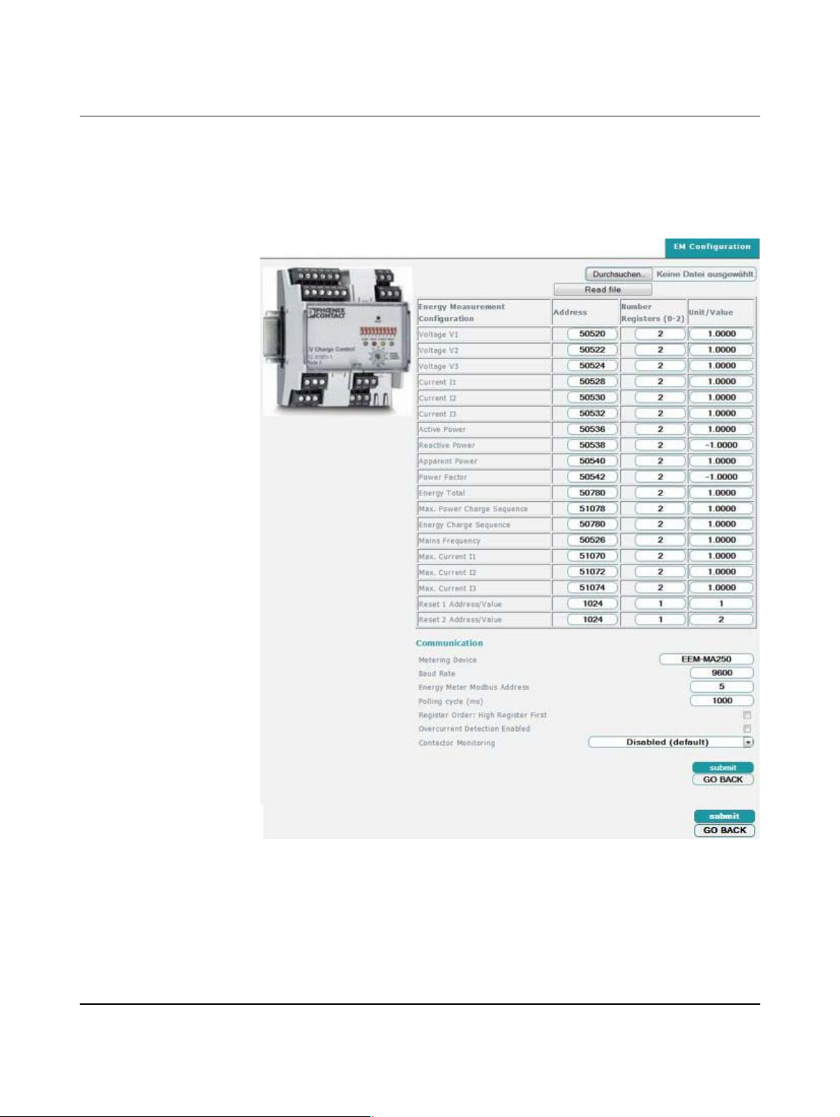
Configuration via web interface
8.5.1 Energy, EM Configuration tab
Different energy meters can be connected to the charging controller which can be configured via the web interface or Modbus TCP. Configuration via the web interface is supported
by the option that allows a complete parameter record to be read with the aid of an xml file
and then transmitted to the device.
Figure 8-5 “Energy, EM Configuration” web interface
Each display value is parameterized using its Modbus address, the data length, and a conversion factor. For parameterization, familiarize yourself with the Modbus communication of
your energy meter.
By default, the interface is configured so that the Phoenix Contact EEM-MA250 energy
meter (Order No. 2901363) can be connected.
104924_en_04 PHOENIX CONTACT 95
Page 96
EV Charge Control
Table 8-6 “Energy, EM Configuration” tab
Parameter Description
Energy Measurement Configuration
Voltage V1
...
Max. Current I3
Address: address of the corresponding measured value in the device in decimal notation
Number Registers (0-2): number of data words the measured value in the meter is pro-
vided with. If “0” is entered here, the corresponding value is not read. This is necessary if
the meter does not provide the corresponding values. Meters that code measured values
in more than two data words cannot be read with the charging controller.
Unit/Value: conversion factor for read measured values for display in the web interface.
Depending on the manufacturer type, the measured values on the meters are provided
with different bit values.
This factor is used to adapt to the specified units (V, A, W, kWh, Hz) for display in the web
interface.
The measured values are stored independently of this value in the Modbus registers of the
charging controller, the data is stored as raw values here. When starting up a new meter
for the first time with the charging controller, we recommend carrying out a plausibility
check for the displayed measured values and adapting the conversion factors, if necessary.
Reset 1 Address/Value and
Reset 2 Address/Value
Certain measured values can be reset in the meter by writing defined values (max. 2 data
word long) to the specified address area. For example, with the EEM-MA250, writing the
value 1 to address 1024 resets the maximum value of currents I1 - I3. The charging controller automatically writes this value after the charging process has been completed
(State A). If the value 0 is entered for number registers (0-2), no values are reset.
Communication
Metering Device The designation identifying the meter used can be freely selected. The designation is dis-
played on the “Energy” tab during operation.
Baud Rate Transmission speed between the charging controller and meter (2.4 kbps; 4.8 kbps; 9.6
kbps; 19.2 kbps; 38.4 kbps). The value set here must match the value set on the meter.
Energy Meter Modbus
Address
Address of the energy meter (0 ... 254). The value set here must match the value set on
the meter.
Polling cycle (ms) Time between two polling cycles. Please note that if the selected cycle time is too short,
this may adversely affect system performance, such as Ethernet communication.
Register Order: High Register First
Overcurrent Detection
This field must be selected if the data in the meter is represented in Big Endian byte sequence. The most significant bit is stored at the smallest memory address.
This field must be selected if surge current monitoring is to be activated.
Enabled
PHOENIX CONTACT 104924_en_04
96
Page 97
Configuration via web interface
Table 8-6 “Energy, EM Configuration” tab [...]
Parameter Description
Contactor Monitoring This function can be used to activate the load contactor monitoring.
The following configurations are possible:
– “disabled”: the load contactor is not checked.
– “Voltage Measurement”: By means of an attached measuring device, it is possible to
measure the voltage at the charging station output. In order to use this configuration,
the dynamic response of the connected meter must be known. The charging controller evaluates the voltage that is read after four polling cycles (“Polling cycle” parameter).
– “Aux. Contact NO”/”Aux. Contact NC”: The charging controller evaluates the N/O or
N/C auxiliary contacts of the load contactor. The evaluation takes place 500 ms after
the load contactor is switched off. The length of time can be adjusted using the Modbus register 519.
Buttons
submit This button transmits the parameters from the charging controller.
GO BACK This button takes you back to the “Energy” tab.
104924_en_04 PHOENIX CONTACT 97
Page 98
EV Charge Control
8.5.2 Configuration file
To simplify the configuration of the connection of energy meters to the charging controller,
the parameters can be imported with the aid of an xml file via the web interface. Tested configuration files can be downloaded in the Download area of the Phoenix Contact website
(phoenixcontact.net/products) for certain energy meters.
<?xml version="1.0"?>
<EVCCConfig>
<EVCCRegAd>
<pV1>50520</pV1>
<pV2>50522</pV2>
<pV3>50524</pV3>
<pI1>50528</pI1>
<pI2>50530</pI2>
<pI3>50532</pI3>
<pACP>50536</pACP>
<pRP>50538</pRP>
<pAPP>50540</pAPP>
<pAF>50542</pAF>
<pESS>50780</pESS>
<pMP>51078</pMP>
<pAAE>50780</pAAE>
<pNF>50526</pNF>
<pI1M>51070</pI1M>
<pI2M>51072</pI2M>
<pI3M>51074</pI3M>
<pReset1>1024</pReset1>
<vReset1>1</vReset1>
<pReset2>1024</pReset2>
<vReset2>2</vReset2>
</EVCCRegAd>
<EVCCReadReg>
<rV1>2</rV1>
<rV2>2</rV2>
<rV3>2</rV3>
<rI1>2</rI1>
<rI2>2</rI2>
<rI3>2</rI3>
<rACP>2</rACP>
<rRP>2</rRP>
<rAPP>2</rAPP>
<rAF>2</rAF>
<rESS>2</rESS>
<rMP>2</rMP>
<rAAE>2</rAAE>
<rNF>2</rNF>
<rI1M>2</rI1M>
<rI2M>2</rI2M>
<rI3M>2</rI3M>
<rReset1>1</rReset1>
<rReset2>1</rReset2>
</EVCCReadReg>
...
Figure 8-6 Configuration file
...
<EVCCUnits>
<uV1>1.0000</uV1>
<uV2>1.0000</uV2>
<uV3>1.0000</uV3>
<uI1>1.0000</uI1>
<uI2>1.0000</uI2>
<uI3>1.0000</uI3>
<uACP>1.0000</uACP>
<uRP>-1.0000</uRP>
<uAPP>1.0000</uAPP>
<uAF>-1.0000</uAF>
<uESS>1.0000</uESS>
<uMP>1.0000</uMP>
<uAAE>1.0000</uAAE>
<uNF>1.0000</uNF>
<uI1M>1.0000</uI1M>
<uI2M>1.0000</uI2M>
<uI3M>1.0000</uI3M>
</EVCCUnits>
<EVCCCfg>
<pBaudrate>9600</pBaudrate>
<pModBus>5</pModBus>
<pPollcycleTm>1000</pPollcycleTm>
<pName>EEM-MA250</pName>
<hrf>false</hrf>
<vOverICutOff>false</vOverICutOff>
<vABVolDet>true</vABVolDet>
<vContMon>3</vContMon>
</EVCCCfg>
</EVCCConfig>
Table 8-7 Explanation of the configuration file
Data area Values in the order of the Energy tab (see Figure 8-4 on
page 93)
EVCCRegAd Addresses of the values to be read
EVCCReadReg Number of data words for the measured values to be read
EVCCUnits Conversion factors for the measured values to be read
EVCCCfg Configuration and communication parameters
PHOENIX CONTACT 104924_en_04
98
Page 99
9 Modbus description
You can access the device registers via Modbus. The device operates as a Modbus slave
using address 180. It waits for incoming Modbus/TCP requests at port 502.
9.1 Register types
Modbus supports four register types which are used as follows.
Table 9-1 Modbus register
Modbus register type Value Access
Input 16 bit Read
Discrete 1 bit Read
Holding 16 bit Read/write
Coils 1 bit Read/write
You can combine several “Input” and “Holding” registers in order to transmit 32-bit data.
Little Endian format is used to code this data, i.e., the word with the least significant element is listed first.
Modbus description
104924_en_04 PHOENIX CONTACT 99
Page 100
EV Charge Control
9.2 Register assignment
The following table shows how the device registers are assigned registers that can be accessed via Modbus.
Table 9-2 Register assignment
Type Address Value Access Function Coding
Input 100 16 bit Read EV status ASCII (8 bit), A ... F
101 16 bit Read Proximity charging current Integer, amperes
102 32 bit Read Charging time Integer, seconds
103
104 16 bit Read DIP switch configuration Binary, DIP 1 = LSB
Every switch corresponds to one bit.
105 32 bit Read Firmware version Decimal, e.g., 0.4.30 = 430
106
107 16 bit Read Error codes Hexadecimal
108 32 bit Read Display meter voltage V1 Decimal
109
110 32 bit Read Display meter voltage V2 Decimal
111
112 32 bit Read Display meter voltage V3 Decimal
113
114 32 bit Read Display meter current I1 Decimal
115
FW[0] = 0; FW[1] = 4; FW[2] = 22;
FW[2] + FW[1] * 100 +
FW[0] * 10,000
Bit Error
1. Cable rejection 13 A and 20 A
2. Cable rejection 13 A
3. Invalid PP value
4. Invalid CP value
5. Status F due to no charging station
availability
6. Locking
7. Unlocking
8. LD unavailable during locking
9. Overcurrent shutdown
10. Communication problem between
charging controller and meter when
overcurrent shutdown is activated
11. Status D, vehicle rejected
12. Contactor failure detected
13. No diode in the Control Pilot circuit on
the vehicle side
PHOENIX CONTACT 104924_en_04
100
 Loading...